Embed Size (px)
Citation preview

Redpine Signals, Inc. Proprietary and Confidential
RS9113 USB Half Mini Card
Datasheet
Version 1.1
October 2015
Redpine Signals, Inc. 2107 N. First Street, #680
San Jose, CA 95131. Tel: (408) 748-3385 Fax: (408) 705-2019
Email: [email protected]
Website: www.redpinesignals.com
Redpine Signals, Inc. Proprietary and Confidential Page 2
RS9113 USB Half Mini Card
Datasheet
Version 1.1
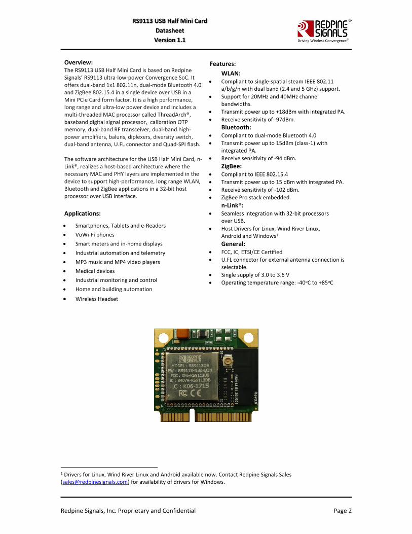
Overview: The RS9113 USB Half Mini Card is based on Redpine Signals’ RS9113 ultra-low-power Convergence SoC. It offers dual-band 1x1 802.11n, dual-mode Bluetooth 4.0 and ZigBee 802.15.4 in a single device over USB in a Mini PCIe Card form factor. It is a high performance, long range and ultra-low power device and includes a multi-threaded MAC processor called ThreadArch®, baseband digital signal processor, calibration OTP memory, dual-band RF transceiver, dual-band high-power amplifiers, baluns, diplexers, diversity switch, dual-band antenna, U.FL connector and Quad-SPI flash. The software architecture for the USB Half Mini Card, n-Link®, realizes a host-based architecture where the necessary MAC and PHY layers are implemented in the device to support high-performance, long range WLAN, Bluetooth and ZigBee applications in a 32-bit host processor over USB interface.
Applications:
Smartphones, Tablets and e-Readers
VoWi-Fi phones
Smart meters and in-home displays
Industrial automation and telemetry
MP3 music and MP4 video players
Medical devices
Industrial monitoring and control
Home and building automation
Wireless Headset
Features:
WLAN: Compliant to single-spatial steam IEEE 802.11
a/b/g/n with dual band (2.4 and 5 GHz) support.
Support for 20MHz and 40MHz channel bandwidths.
Transmit power up to +18dBm with integrated PA.
Receive sensitivity of -97dBm.
Bluetooth: Compliant to dual-mode Bluetooth 4.0
Transmit power up to 15dBm (class-1) with integrated PA.
Receive sensitivity of -94 dBm.
ZigBee: Compliant to IEEE 802.15.4
Transmit power up to 15 dBm with integrated PA.
Receive sensitivity of -102 dBm.
ZigBee Pro stack embedded.
n-Link®: Seamless integration with 32-bit processors
over USB.
Host Drivers for Linux, Wind River Linux, Android and Windows1
General: FCC, IC, ETSI/CE Certified
U.FL connector for external antenna connection is selectable.
Single supply of 3.0 to 3.6 V
Operating temperature range: -40oC to +85oC
1 Drivers for Linux, Wind River Linux and Android available now. Contact Redpine Signals Sales ([email protected]) for availability of drivers for Windows.
Redpine Signals, Inc. Proprietary and Confidential Page 3
RS9113 USB Half Mini Card
Datasheet
Version 1.1
About this Document This document describes the RS9113 USB Half Mini Card’s specifications. The document covers the hardware and software features, package descriptions, pin descriptions, interface specifications, electrical characteristics, certification information and ordering information.
Disclaimer: The information in this document pertains to information related to Redpine Signals, Inc. products. This information is provided as a service to our customers, and may be used for information purposes only. Redpine assumes no liabilities or responsibilities for errors or omissions in this document. This document may be changed at any time at Redpine’s sole discretion without any prior notice to anyone. Redpine is not committed to updating this document in the future.
Copyright © 2015 Redpine Signals, Inc. All rights reserved.
Redpine Signals, Inc. Proprietary and Confidential Page 4
RS9113 USB Half Mini Card
Datasheet
Version 1.1
Table of Contents
1 Overview .............................................................................................................. 6 1.1 Block Diagram ..........................................................................................................6 1.2 Product Naming and Variants ...................................................................................6
2 Features ............................................................................................................... 8
3 Package Description ........................................................................................... 13 3.1 Mechanical Characteristics ...................................................................................... 13 3.2 Half Mini Card Dimensions ...................................................................................... 13
4 Pinout and Pin Description .................................................................................. 14 4.1 Pinout of the RS9113 USB Half Mini Card ................................................................. 14 4.2 Pin Description ....................................................................................................... 15
5 Specifications ..................................................................................................... 17 5.1 Absolute Maximum Ratings .................................................................................... 17 5.2 Recommended Operating Conditions ...................................................................... 17 5.3 DC Characteristics – Digital I/O Signals .................................................................... 17 5.4 AC Characteristics ................................................................................................... 18
5.4.1 USB Interface ........................................................................................................................ 18 5.4.1.1 Timing Characteristics ....................................................................................................... 18 5.4.1.2 Electrical Characteristics ................................................................................................... 18 5.4.1.3 Voltage Thresholds ........................................................................................................... 18
5.4.2 Reset Timing ......................................................................................................................... 19 5.5 Regulatory Specifications ........................................................................................ 19
6 Software Architecture ......................................................................................... 20 6.1 n-Link® Software Architecture ................................................................................. 20
6.1.1 Operating System Support.................................................................................................... 21
7 Ordering Information .......................................................................................... 22 7.1 Collateral ................................................................................................................ 22 7.2 Packing Information ............................................................................................... 22 7.3 Contact Information ............................................................................................... 22
Table of Figures Figure 1: Block Diagram of RS9113 USB Half Mini Card ............................................................................ 6 Figure 2: RS9113 USB Half Mini Card Naming Convention ........................................................................ 7 Figure 3: Package Dimensions ................................................................................................................ 13 Figure 4: Reset Timing ............................................................................................................................ 19 Figure 5: n-Link® Software Architecture ................................................................................................. 20 Figure 6: Mechanical Details of Tray ...................................................................................................... 22
Table of Tables Table 1: RS9113 USB Half Mini Card Features ........................................................................................ 12 Table 2: Mechanical Dimensions ............................................................................................................ 13 Table 4: Pin Descriptions ........................................................................................................................ 16 Table 5: Absolute Maximum Ratings ...................................................................................................... 17
Redpine Signals, Inc. Proprietary and Confidential Page 5
RS9113 USB Half Mini Card
Datasheet
Version 1.1
Table 6: Recommended Operating Conditions ....................................................................................... 17 Table 7: Input/Output DC Characteristics ............................................................................................... 18 Table 8: Timing Characteristics for USB Interface ................................................................................... 18 Table 9: Electrical Characteristics for USB Interface ............................................................................... 18 Table 10: Input/Output DC Characteristics ............................................................................................. 19 Table 11: Regulatory Certifications ........................................................................................................ 19

Redpine Signals, Inc. Proprietary and Confidential Page 6
RS9113 USB Half Mini Card
Datasheet
Version 1.1
1 Overview
The RS9113 USB Half Mini Cards are multi-wireless Combo devices based on Redpine Signals’ RS9113 ultra-low-power Convergence SoC.
They offer dual-band 1x1 802.11n, dual-mode Bluetooth 4.0 and ZigBee 802.15.4 in a single device over USB in a Mini PCIe Card form factor. They are high-performance devices which realize a zero-host architecture. The necessary MAC and PHY layers are implemented in the device to support WLAN, Bluetooth and ZigBee applications and they interface with 32-bit host processors over USB interface.
They include a multi-threaded MAC processor called ThreadArch®, baseband digital signal processor, calibration OTP memory, dual-band RF transceiver, dual-band high-power amplifiers, baluns, diplexers, diversity switch, dual-band antenna, U.FL connector and Quad-SPI flash.
1.1 Block Diagram
The following figure is the block diagram for the RS9113 USB Half Mini Card.
Figure 1: Block Diagram of RS9113 USB Half Mini Card
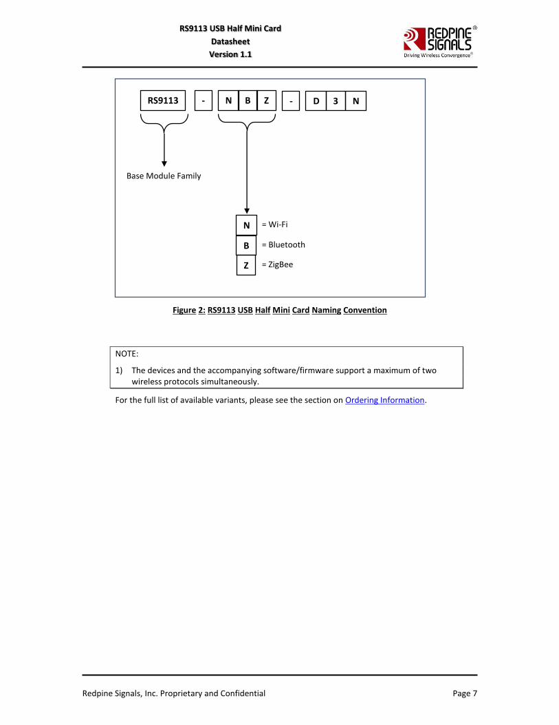
1.2 Product Naming and Variants
The figure below shows the naming convention for the USB Half Mini Card’s variants.
Redpine Signals, Inc. Proprietary and Confidential Page 7
RS9113 USB Half Mini Card
Datasheet
Version 1.1
Figure 2: RS9113 USB Half Mini Card Naming Convention
NOTE:
1) The devices and the accompanying software/firmware support a maximum of two wireless protocols simultaneously.
For the full list of available variants, please see the section on Ordering Information.
RS9113 - N B Z - D 3 N
N
B
Z
= Wi-Fi
= Bluetooth
= ZigBee
Base Module Family
Redpine Signals, Inc. Proprietary and Confidential Page 8
RS9113 USB Half Mini Card
Datasheet
Version 1.1
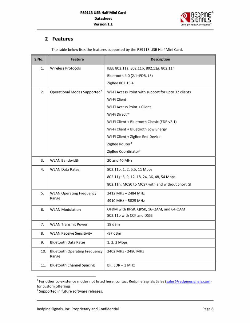
2 Features
The table below lists the features supported by the RS9113 USB Half Mini Card.
S.No. Feature Description
1. Wireless Protocols IEEE 802.11a, 802.11b, 802.11g, 802.11n
Bluetooth 4.0 (2.1+EDR, LE)
ZigBee 802.15.4
2. Operational Modes Supported2 Wi-Fi Access Point with support for upto 32 clients
Wi-Fi Client
Wi-Fi Access Point + Client
Wi-Fi Direct™
Wi-Fi Client + Bluetooth Classic (EDR v2.1)
Wi-Fi Client + Bluetooth Low Energy
Wi-Fi Client + ZigBee End Device
ZigBee Router3
ZigBee Coordinator3
3. WLAN Bandwidth 20 and 40 MHz
4. WLAN Data Rates 802.11b: 1, 2, 5.5, 11 Mbps
802.11g: 6, 9, 12, 18, 24, 36, 48, 54 Mbps
802.11n: MCS0 to MCS7 with and without Short GI
5. WLAN Operating Frequency Range
2412 MHz – 2484 MHz
4910 MHz – 5825 MHz
6. WLAN Modulation OFDM with BPSK, QPSK, 16-QAM, and 64-QAM
802.11b with CCK and DSSS
7. WLAN Transmit Power 18 dBm
8. WLAN Receive Sensitivity -97 dBm
9. Bluetooth Data Rates 1, 2, 3 Mbps
10. Bluetooth Operating Frequency Range
2402 MHz - 2480 MHz
11. Bluetooth Channel Spacing BR, EDR – 1 MHz
2 For other co-existence modes not listed here, contact Redpine Signals Sales ([email protected]) for custom offerings. 3 Supported in future software releases.

Redpine Signals, Inc. Proprietary and Confidential Page 9
RS9113 USB Half Mini Card
Datasheet
Version 1.1
S.No. Feature Description
LE – 2 MHz
12. Bluetooth Modulation GFSK, DQPSK, 8DPSK
13. Bluetooth Transmit Power 15 dBm (Class-1)
14. Bluetooth Receive Sensitivity -94 dBm
15. ZigBee Data Rate 250 kbps
16. ZigBee Operating Frequency Range
2405 MHz - 2480 MHz
17. ZigBee Modulation DSSS
18. ZigBee Transmit Power 15 dBm
19. ZigBee Receive Sensitivity -102 dBm
20. Deep Sleep Current Consumption
< 10 µA in disconnected state
< 30 µA in connected state
21. Host Interfaces USB 2.0
22. USB Host Interface Supports 480 Mbps High Speed (HS) mode and 12 Mbps Full Speed (FS) modes.
23. Software Architecture Architecture for Zero Host Load for Datapath. Refer to the Software Architecture section for more details.
24. Wireless Security Features WPA/WPA2 Personal
WPA/WPA2 Enterprise Security
WPS
25. Advanced Security Features4 PUF Based Security
AES 128/256-bit
RSA
SHA, SHA256
ECDH
26. Application throughputs5 Upto 90 Mbps UDP
Upto 70 Mbps TCP
4 These features are not part of the standard firmware. Contact Redpine Signals Sales ([email protected]) for details. 5 The throughputs mentioned here have been recorded in an ideal environment over USB. Throughputs observed in other environments might differ based on the host interface speeds (e.g., SPI clock frequency, UART Baud Rate, etc.), wireless medium, physical obstacles, distance, etc.

Redpine Signals, Inc. Proprietary and Confidential Page 10
RS9113 USB Half Mini Card
Datasheet
Version 1.1
S.No. Feature Description
27. Operating Temperature Range -40oC to +85oC
28. Supply Voltages and Options Single 3.0 to 3.6V Supply
29. WLAN Features Dynamic selection of data rate depending on the channel statistics.
Hardware accelerators for WEP 64/128-bit, TKIP, AES and WPS
Support for WMM
Support for AMPDU Aggregation/De-aggregation and AMSDU De-aggregation
Support for IEEE 802.11d/e/I, 802.11j6, 802.11w/k/v/r/h6
30. Bluetooth Features Supports Classic mode piconet with seven active slaves7.
Supports Low Energy mode with seven active slaves8.
Supports scatternet with two slave roles or one master role and one slave role while being visible9.
Proprietary Mode to support 15 active slaves by using the “reserved” bit6.
Bluetooth security features: Authentication, Pairing and Encryption.
Supports low power connection states such as hold, sniff and park modes with selectable sniff intervals10.
Adaptive Frequency Hopping (AFH), Interlaced scanning, Quality of Service, Channel Quality Driven Data Rate6.
Channel assessment algorithm provides fast and accurate determination of occupied channels for use in adaptive frequency hopping mode6.
Proprietary FEC for DQPSK and 8-PSK modes.
Provides finer granularity of range vs. throughput control.
31. Bluetooth Profiles/Protocols All profiles are to be implemented in the Host.
32. ZigBee Features MAC:
Supported modes: ZigBee Coordinator, Router11, End device.
6 Supported in future software releases. 7 Current software releases support one slave. 8 Current software releases support three slaves. 9 Supported in future software releases. 10 Hold and Park supported in future software releases. 11 Coordinator and Router modes supported in future software releases.
Redpine Signals, Inc. Proprietary and Confidential Page 11
RS9113 USB Half Mini Card
Datasheet
Version 1.1
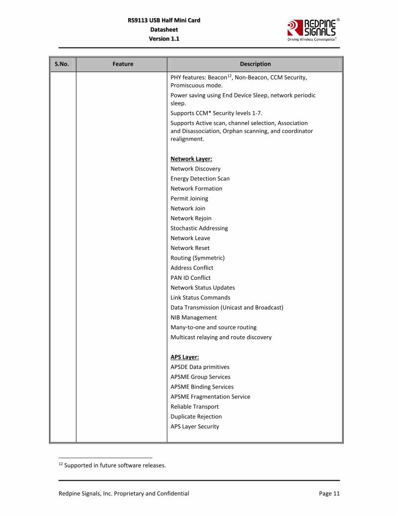
S.No. Feature Description
PHY features: Beacon12, Non-Beacon, CCM Security, Promiscuous mode.
Power saving using End Device Sleep, network periodic sleep.
Supports CCM* Security levels 1-7.
Supports Active scan, channel selection, Association and Disassociation, Orphan scanning, and coordinator realignment.
Network Layer:
Network Discovery
Energy Detection Scan
Network Formation
Permit Joining
Network Join
Network Rejoin
Stochastic Addressing
Network Leave
Network Reset
Routing (Symmetric)
Address Conflict
PAN ID Conflict
Network Status Updates
Link Status Commands
Data Transmission (Unicast and Broadcast)
NIB Management
Many-to-one and source routing
Multicast relaying and route discovery
APS Layer:
APSDE Data primitives
APSME Group Services
APSME Binding Services
APSME Fragmentation Service
Reliable Transport
Duplicate Rejection
APS Layer Security
12 Supported in future software releases.
Redpine Signals, Inc. Proprietary and Confidential Page 12
RS9113 USB Half Mini Card
Datasheet
Version 1.1
S.No. Feature Description
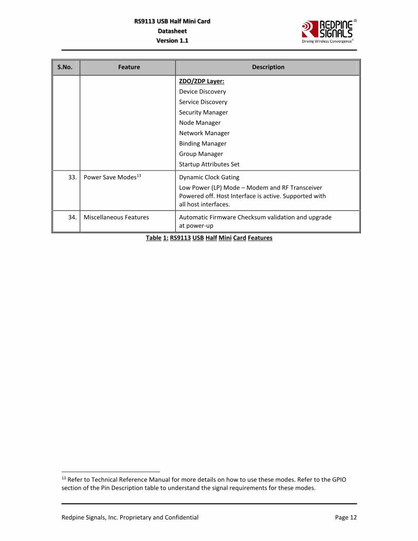
ZDO/ZDP Layer:
Device Discovery
Service Discovery
Security Manager
Node Manager
Network Manager
Binding Manager
Group Manager
Startup Attributes Set
33. Power Save Modes13 Dynamic Clock Gating
Low Power (LP) Mode – Modem and RF Transceiver Powered off. Host Interface is active. Supported with all host interfaces.
34. Miscellaneous Features Automatic Firmware Checksum validation and upgrade at power-up
Table 1: RS9113 USB Half Mini Card Features
13 Refer to Technical Reference Manual for more details on how to use these modes. Refer to the GPIO section of the Pin Description table to understand the signal requirements for these modes.
Redpine Signals, Inc. Proprietary and Confidential Page 13
RS9113 USB Half Mini Card
Datasheet
Version 1.1
3 Package Description
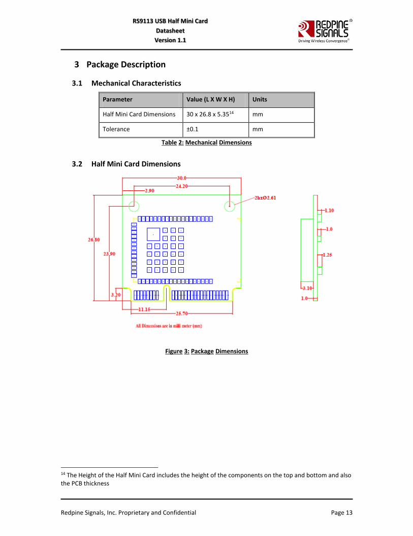
3.1 Mechanical Characteristics
Parameter Value (L X W X H) Units
Half Mini Card Dimensions 30 x 26.8 x 5.3514 mm
Tolerance ±0.1 mm
Table 2: Mechanical Dimensions
3.2 Half Mini Card Dimensions
Figure 3: Package Dimensions
14 The Height of the Half Mini Card includes the height of the components on the top and bottom and also the PCB thickness
Redpine Signals, Inc. Proprietary and Confidential Page 14
RS9113 USB Half Mini Card
Datasheet
Version 1.1
4 Pinout and Pin Description
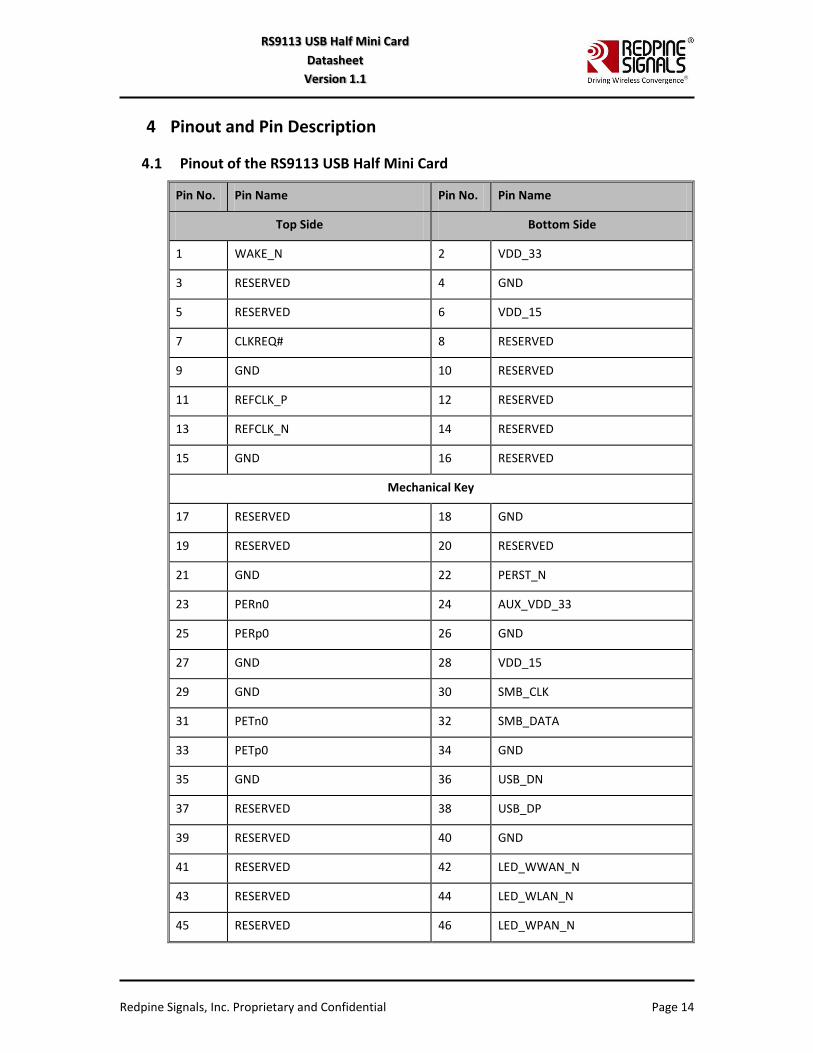
4.1 Pinout of the RS9113 USB Half Mini Card
Pin No. Pin Name Pin No. Pin Name
Top Side Bottom Side
1 WAKE_N 2 VDD_33
3 RESERVED 4 GND
5 RESERVED 6 VDD_15
7 CLKREQ# 8 RESERVED
9 GND 10 RESERVED
11 REFCLK_P 12 RESERVED
13 REFCLK_N 14 RESERVED
15 GND 16 RESERVED
Mechanical Key
17 RESERVED 18 GND
19 RESERVED 20 RESERVED
21 GND 22 PERST_N
23 PERn0 24 AUX_VDD_33
25 PERp0 26 GND
27 GND 28 VDD_15
29 GND 30 SMB_CLK
31 PETn0 32 SMB_DATA
33 PETp0 34 GND
35 GND 36 USB_DN
37 RESERVED 38 USB_DP
39 RESERVED 40 GND
41 RESERVED 42 LED_WWAN_N
43 RESERVED 44 LED_WLAN_N
45 RESERVED 46 LED_WPAN_N
Redpine Signals, Inc. Proprietary and Confidential Page 15
RS9113 USB Half Mini Card
Datasheet
Version 1.1
Pin No. Pin Name Pin No. Pin Name
Top Side Bottom Side
47 RESERVED 48 VDD_15
49 RESERVED 50 GND
51 RESERVED 52 VDD_33
Table 3: Pinout of the USB Half Mini Card
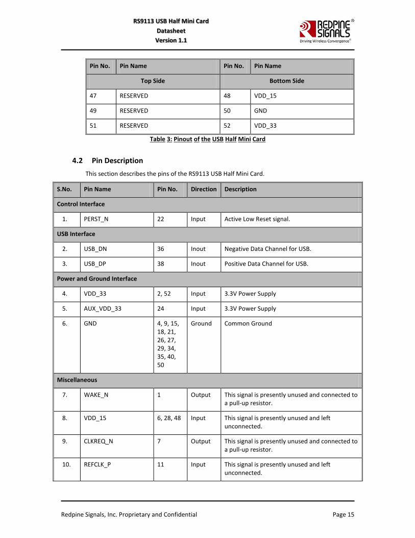
4.2 Pin Description
This section describes the pins of the RS9113 USB Half Mini Card.
S.No. Pin Name Pin No. Direction Description
Control Interface
1. PERST_N 22 Input Active Low Reset signal.
USB Interface
2. USB_DN 36 Inout Negative Data Channel for USB.
3. USB_DP 38 Inout Positive Data Channel for USB.
Power and Ground Interface
4. VDD_33 2, 52 Input 3.3V Power Supply
5. AUX_VDD_33 24 Input 3.3V Power Supply
6. GND 4, 9, 15, 18, 21, 26, 27, 29, 34, 35, 40, 50
Ground Common Ground
Miscellaneous
7. WAKE_N 1 Output This signal is presently unused and connected to a pull-up resistor.
8. VDD_15 6, 28, 48 Input This signal is presently unused and left unconnected.
9. CLKREQ_N 7 Output This signal is presently unused and connected to a pull-up resistor.
10. REFCLK_P 11 Input This signal is presently unused and left unconnected.
Redpine Signals, Inc. Proprietary and Confidential Page 16
RS9113 USB Half Mini Card
Datasheet
Version 1.1
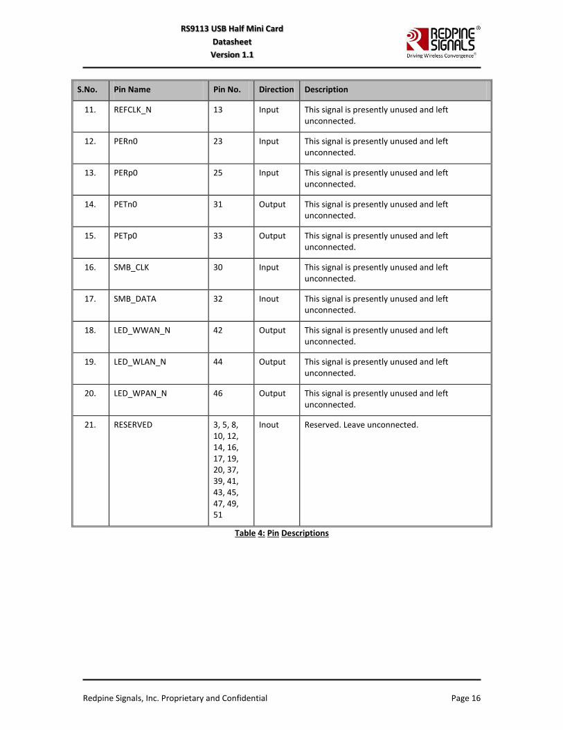
S.No. Pin Name Pin No. Direction Description
11. REFCLK_N 13 Input This signal is presently unused and left unconnected.
12. PERn0 23 Input This signal is presently unused and left unconnected.
13. PERp0 25 Input This signal is presently unused and left unconnected.
14. PETn0 31 Output This signal is presently unused and left unconnected.
15. PETp0 33 Output This signal is presently unused and left unconnected.
16. SMB_CLK 30 Input This signal is presently unused and left unconnected.
17. SMB_DATA 32 Inout This signal is presently unused and left unconnected.
18. LED_WWAN_N 42 Output This signal is presently unused and left unconnected.
19. LED_WLAN_N 44 Output This signal is presently unused and left unconnected.
20. LED_WPAN_N 46 Output This signal is presently unused and left unconnected.
21. RESERVED 3, 5, 8, 10, 12, 14, 16, 17, 19, 20, 37, 39, 41, 43, 45, 47, 49, 51
Inout Reserved. Leave unconnected.
Table 4: Pin Descriptions
Redpine Signals, Inc. Proprietary and Confidential Page 17
RS9113 USB Half Mini Card
Datasheet
Version 1.1
5 Specifications
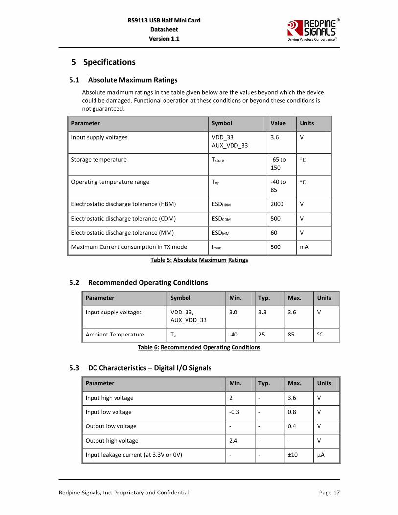
5.1 Absolute Maximum Ratings
Absolute maximum ratings in the table given below are the values beyond which the device could be damaged. Functional operation at these conditions or beyond these conditions is not guaranteed.
Parameter Symbol Value Units
Input supply voltages VDD_33, AUX_VDD_33
3.6 V
Storage temperature Tstore -65 to 150
C
Operating temperature range Top -40 to 85
C
Electrostatic discharge tolerance (HBM) ESDHBM 2000 V
Electrostatic discharge tolerance (CDM) ESDCDM 500 V
Electrostatic discharge tolerance (MM) ESDMM 60 V
Maximum Current consumption in TX mode Imax 500 mA
Table 5: Absolute Maximum Ratings
5.2 Recommended Operating Conditions
Parameter Symbol Min. Typ. Max. Units
Input supply voltages VDD_33, AUX_VDD_33
3.0 3.3 3.6 V
Ambient Temperature Ta -40 25 85 oC
Table 6: Recommended Operating Conditions
5.3 DC Characteristics – Digital I/O Signals
Parameter Min. Typ. Max. Units
Input high voltage 2 - 3.6 V
Input low voltage -0.3 - 0.8 V
Output low voltage - - 0.4 V
Output high voltage 2.4 - - V
Input leakage current (at 3.3V or 0V) - - ±10 µA

Redpine Signals, Inc. Proprietary and Confidential Page 18
RS9113 USB Half Mini Card
Datasheet
Version 1.1
Parameter Min. Typ. Max. Units
Tristate output leakage current (at 3.3V or 0V - - ±10 µA
Table 7: Input/Output DC Characteristics
5.4 AC Characteristics
5.4.1 USB Interface
5.4.1.1 Timing Characteristics
Parameter Conditions Min. Typ. Max. Units
trise 1.5 Mbps
12 Mbps
480 Mbps
75
4
0.5
-
-
-
300
20
-
ns
tfall 1.5 Mbps
12 Mbps
480 Mbps
75
4
0.5
-
-
-
300
20
-
ns
Jitter 1.5 Mbps
12 Mbps
480 Mbps
-
-
-
-
-
-
10
1
0.2
ns
Table 8: Timing Characteristics for USB Interface
5.4.1.2 Electrical Characteristics
Parameter Conditions Min. Typ. Max. Units
Vcm DC (DC level measured at receiver connector)
HS Mode
LS/FS Mode
-0.05
0.8
-
-
0.5
2.5
V
Crossover Voltages LS Mode
FS Mode
1.3
1.3
-
-
2
2
V
Power supply ripple noise (Analog 3.3V)
< 160 MHz -50 - 50 mV
Table 9: Electrical Characteristics for USB Interface
5.4.1.3 Voltage Thresholds
Parameter Min. Typ. Max. Units
A-Device Session Valid 0.8 1.4 2.0 V
B-Device Session Valid 0.8 1.4 4.0 V
Redpine Signals, Inc. Proprietary and Confidential Page 19
RS9113 USB Half Mini Card
Datasheet
Version 1.1
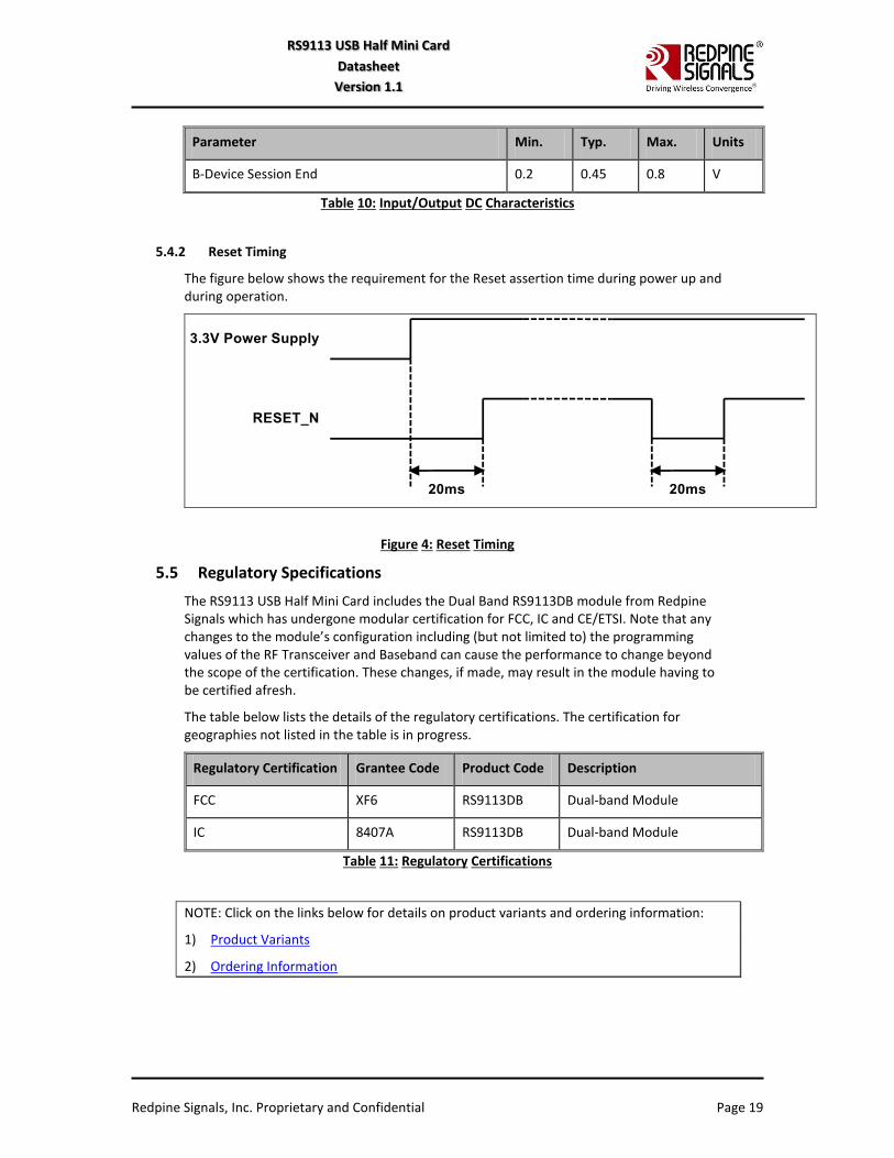
Parameter Min. Typ. Max. Units
B-Device Session End 0.2 0.45 0.8 V
Table 10: Input/Output DC Characteristics
5.4.2 Reset Timing
The figure below shows the requirement for the Reset assertion time during power up and during operation.
Figure 4: Reset Timing
5.5 Regulatory Specifications
The RS9113 USB Half Mini Card includes the Dual Band RS9113DB module from Redpine Signals which has undergone modular certification for FCC, IC and CE/ETSI. Note that any changes to the module’s configuration including (but not limited to) the programming values of the RF Transceiver and Baseband can cause the performance to change beyond the scope of the certification. These changes, if made, may result in the module having to be certified afresh.
The table below lists the details of the regulatory certifications. The certification for geographies not listed in the table is in progress.
Regulatory Certification Grantee Code Product Code Description
FCC XF6 RS9113DB Dual-band Module
IC 8407A RS9113DB Dual-band Module
Table 11: Regulatory Certifications
NOTE: Click on the links below for details on product variants and ordering information:
1) Product Variants
2) Ordering Information
Redpine Signals, Inc. Proprietary and Confidential Page 20
RS9113 USB Half Mini Card
Datasheet
Version 1.1
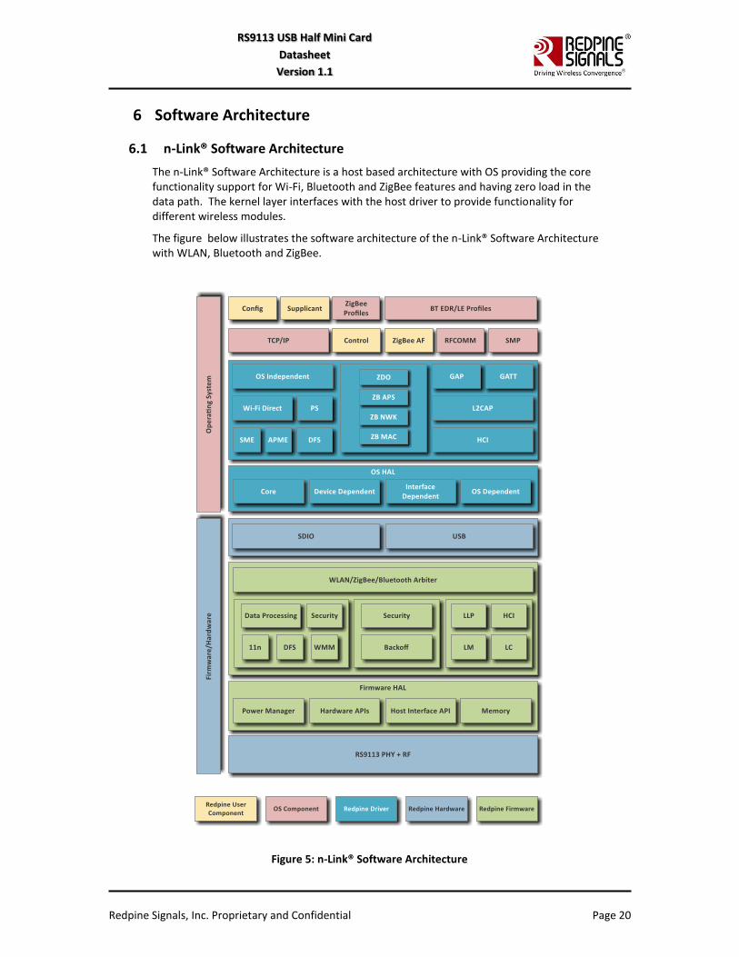
6 Software Architecture
6.1 n-Link® Software Architecture
The n-Link® Software Architecture is a host based architecture with OS providing the core functionality support for Wi-Fi, Bluetooth and ZigBee features and having zero load in the data path. The kernel layer interfaces with the host driver to provide functionality for different wireless modules.
The figure below illustrates the software architecture of the n-Link® Software Architecture with WLAN, Bluetooth and ZigBee.
Figure 5: n-Link® Software Architecture
Redpine Signals, Inc. Proprietary and Confidential Page 21
RS9113 USB Half Mini Card
Datasheet
Version 1.1
6.1.1 Operating System Support
The n-Link drivers for the RS9113 USB Half Mini Card are presently available for the following OS’:
1) Linux OS (kernel versions 2.6.30 to 3.16)
2) Wind River Linux (kernel version 3.4.91)
3) Android 4.4.3
Operating Systems to be supported in the future include WCE2013 and WCE7.

Redpine Signals, Inc. Proprietary and Confidential Page 22
RS9113 USB Half Mini Card
Datasheet
Version 1.1
7 Ordering Information
The RS9113 USB Half Mini Card has the following variants.
Part # Wi-Fi
2.4GHz Wi-Fi 5GHz BT ZB
Integrated Antenna &
U.FL SW Variant
RS9113-NBZ-D3N Y Y Y Y Y n-Link®
Table 12: RS9113 USB Half Mini Card Variants
7.1 Collateral
The following documentation and software are available along with the RS9113 USB Half Mini Card.
Datasheet
Device drivers
Technical Reference Manual
7.2 Packing Information
The Half Mini Cards are packaged and shipped in Trays.
Each tray can accommodate 36 cards. The mechanical details of the tray are given in the figure below.
Figure 6: Mechanical Details of Tray
7.3 Contact Information
For additional information, please contact Sales at Redpine Signals, Inc.
Redpine Signals, Inc.
Redpine Signals, Inc. Proprietary and Confidential Page 23
RS9113 USB Half Mini Card
Datasheet
Version 1.1
2107 North First Street, Suite 680,
San Jose, CA 95131 USA
Phone: +1 408 748 3385
E-mail: [email protected]
Website: http://www.redpinesignals.com/
*****

Redpine Signals, Inc. Proprietary and Confidential Page 24
RS9113 USB Half Mini Card
Datasheet
Version 1.1
Revision History
Revision No.
Version No.
Date Changes
1. 1.0 June 2015 Initial Version
2. 1.1 June 2015 1) Added Packing Information in Section 7.2.
2) Updated the Product Variants and Part Numbering sections.


![G2 - OPERATING PROCEDURES [5 Exam Questions -- 5 Groups] G2A Phone operating procedures; USB/LSB utilization conventions; procedural signals; breaking](https://img.pdfslide.us/doc/110x75/56649c7b5503460f9492fc52/g2-operating-procedures-5-exam-questions-5-groups-g2a-phone-operating.jpg)