Embed Size (px)
Citation preview

R&S® FSV-K82/-K83CDMA2000 AnalysisOperating Manual
Oper
ating
Man
ual
1176.7626.02 ─ 05(;ÚÚJ2)
Test
& Me
asur
emen
t

This manual describes the following R&S®FSV/FSVA options:● R&S FSVR&S FSV-K82 (1310.8703.02)
● R&S FSV-K83 (1310.8755.02)
This manual describes the following R&S FSV/FSVA models with firmware version 3.00 and higher:● R&S®FSV4 (1321.3008K04)
● R&S®FSVA4 (1321.3008K05)
● R&S®FSV7 (1321.3008K07)
● R&S®FSVA7 (1321.3008K08)
● R&S®FSV13 (1321.3008K13)
● R&S®FSVA13 (1321.3008K14)
● R&S®FSV30 (1321.3008K30)
● R&S®FSVA30 (1321.3008K31)
● R&S®FSV40 (1321.3008K39/1321.3008K40)
● R&S®FSVA40 (1321.3008K41)
It also applies to the following R&S®FSV models. However, note the differences described in Chapter 1.4,"Notes for Users of R&S FSV 1307.9002Kxx Models", on page 9.● R&S®FSV3 (1307.9002K03)
● R&S®FSV7 (1307.9002K07)
● R&S®FSV13 (1307.9002K13)
● R&S®FSV30 (1307.9002K30)
● R&S®FSV40 (1307.9002K39/1307.9002K40)
© 2015 Rohde & Schwarz GmbH & Co. KGMühldorfstr. 15, 81671 München, GermanyPhone: +49 89 41 29 - 0Fax: +49 89 41 29 12 164Email: [email protected]: www.rohde-schwarz.comSubject to change – Data without tolerance limits is not binding.R&S® is a registered trademark of Rohde & Schwarz GmbH & Co. KG.CDMA2000® is a registered trademark of the Telecommunications Industry Association (TIA -USA).Trade names are trademarks of the owners.
The following abbreviations are used throughout this manual: R&S®FSV/FSVA is abbreviated as R&S FSV/FSVA.

ContentsR&S® FSV-K82/-K83
3Operating Manual 1176.7626.02 ─ 05
Contents1 Preface.................................................................................................... 5
1.1 Documentation Overview............................................................................................. 5
1.2 Conventions Used in the Documentation...................................................................7
1.3 How to Use the Help System........................................................................................8
1.4 Notes for Users of R&S FSV 1307.9002Kxx Models.................................................. 9
2 Introduction.......................................................................................... 10
3 Test Setup for Base Station or Mobile Station Tests........................11
4 Measurement Examples for the CDMA2000 BTS Analysis (optionK82)....................................................................................................... 13
4.1 Test Setup for Base Station Tests.............................................................................13
4.2 Measuring the Signal Channel Power....................................................................... 15
4.3 Measuring the Spectrum Emission Mask................................................................. 15
4.4 Measuring the Relative Code Domain Power and Frequency Error.......................17
4.5 Measuring the Triggered Relative Code Domain Power......................................... 19
4.6 Measuring the Composite EVM................................................................................. 21
4.7 Measuring the Peak Code Domain Error and the RHO Factor................................22
5 Measurement Examples for the CDMA2000 MS Analysis (optionK83)....................................................................................................... 24
5.1 Test Setup for Base Station or Mobile Station Tests...............................................24
5.2 Measuring the Signal Channel Power....................................................................... 26
5.3 Measuring the Spectrum Emission Mask................................................................. 27
5.4 Measuring the Relative Code Domain Power and Frequency Error.......................28
5.5 Measuring the Triggered Relative Code Domain Power......................................... 30
5.6 Measuring the Composite EVM................................................................................. 31
5.7 Measuring the Peak Code Domain Error and the RHO Factor................................33
6 Instrument Functions of the CDMA2000 Analysis............................356.1 Measurements and Result Displays..........................................................................35
6.2 Menu and Softkey Description for CDA Measurements..........................................57
6.3 Softkeys and Menus for RF Measurements (K82)....................................................97
6.4 Further Information...................................................................................................151

ContentsR&S® FSV-K82/-K83
4Operating Manual 1176.7626.02 ─ 05
7 Remote Commands of the CDMA2000 BTS Analysis.....................1787.1 Notation......................................................................................................................179
7.2 CALCulate Subsystem..............................................................................................181
7.3 CONFigure Subsystem............................................................................................. 224
7.4 DISPlay Subsystem...................................................................................................235
7.5 INSTrument Subsystem............................................................................................242
7.6 SENSe Subsystem.................................................................................................... 243
7.7 STATus subsystem...................................................................................................290
7.8 TRACe Subsystem.................................................................................................... 291
7.9 Other Commands Referenced in this Manual........................................................ 300
8 Status Reporting System of the CDMA2000 BTS Analysis (optionK82)..................................................................................................... 315
9 Glossary..............................................................................................316
10 Appendix.............................................................................................317
List of Commands..............................................................................320
Index....................................................................................................326

PrefaceR&S® FSV-K82/-K83
5Operating Manual 1176.7626.02 ─ 05
1 Preface
1.1 Documentation Overview
The user documentation for the R&S FSV/FSVA is divided as follows:
● Quick Start Guide● Operating Manuals for base unit and options● Service Manual● Online Help● Release Notes
Quick Start Guide
This manual is delivered with the instrument in printed form and in PDF format on theCD. It provides the information needed to set up and start working with the instrument.Basic operations and basic measurements are described. Also a brief introduction toremote control is given. The manual includes general information (e.g. Safety Instruc-tions) and the following chapters:
Chapter 1 Introduction, General information
Chapter 2 Front and Rear Panel
Chapter 3 Preparing for Use
Chapter 4 Firmware Update and Installation of Firmware Options
Chapter 5 Basic Operations
Chapter 6 Basic Measurement Examples
Chapter 7 Brief Introduction to Remote Control
Appendix LAN Interface
Operating Manuals
The Operating Manuals are a supplement to the Quick Start Guide. Operating Manualsare provided for the base unit and each additional (software) option.
The Operating Manual for the base unit provides basic information on operating theR&S FSV/FSVA in general, and the "Spectrum" mode in particular. Furthermore, thesoftware options that enhance the basic functionality for various measurement modesare described here. The set of measurement examples in the Quick Start Guide isexpanded by more advanced measurement examples. In addition to the brief introduc-tion to remote control in the Quick Start Guide, a description of the basic analyzer com-mands and programming examples is given. Information on maintenance, instrumentinterfaces and error messages is also provided.
In the individual option manuals, the specific instrument functions of the option aredescribed in detail. For additional information on default settings and parameters, refer
Documentation Overview

PrefaceR&S® FSV-K82/-K83
6Operating Manual 1176.7626.02 ─ 05
to the data sheets. Basic information on operating the R&S FSV/FSVA is not includedin the option manuals.
The following Operating Manuals are available for the R&S FSV/FSVA:
● R&S FSV/FSVA base unit; in addition:– R&S FSV-K9 Power Sensor Support– R&S FSV-K14 Spectrogram Measurement
● R&S FSV-K7 Analog Demodulation and R&S FSV-K7S FM Stereo Measurements● R&S FSV-K10 GSM/EDGE Measurement● R&S FSV-K30 Noise Figure Measurement● R&S FSV-K40 Phase Noise Measurement● R&S FSV-K70 Vector Signal Analysis Operating Manual
R&S FSV-K70 Vector Signal Analysis Getting Started (First measurements)● R&S FSV-K72 3GPP FDD BTS Analysis● R&S FSV-K73 3GPP FDD UE Analysis● R&S FSV-K76/77 3GPP TD-SCDMA BTS/UE Measurement● R&S FSV-K82/83 CDMA2000 BTS/MS Analysis● R&S FSV-K84/85 1xEV-DO BTS/MS Analysis● R&S FSV-K91 WLAN IEEE 802.11● R&S FSV-K93 WiMAX IEEE 802.16 OFDM/OFDMA Analysis● R&S FSV-K100/K104 EUTRA / LTE Downlink Measurement Application● R&S FSV-K101/K105 EUTRA / LTE Uplink Measurement Application
These manuals are available in PDF format on the CD delivered with the instrument.
Service Manual
This manual is available in PDF format on the CD delivered with the instrument. Itdescribes how to check compliance with rated specifications, instrument function,repair, troubleshooting and fault elimination. It contains all information required forrepairing the R&S FSV/FSVA by replacing modules. The manual includes the followingchapters:
Chapter 1 Performance Test
Chapter 2 Adjustment
Chapter 3 Repair
Chapter 4 Software Update / Installing Options
Chapter 5 Documents
Online Help
The online help contains context-specific help on operating the R&S FSV/FSVA and allavailable options. It describes both manual and remote operation. The online help isinstalled on the R&S FSV/FSVA by default, and is also available as an executa-ble .chm file on the CD delivered with the instrument.
Documentation Overview

PrefaceR&S® FSV-K82/-K83
7Operating Manual 1176.7626.02 ─ 05
Release Notes
The release notes describe the installation of the firmware, new and modified func-tions, eliminated problems, and last minute changes to the documentation. The corre-sponding firmware version is indicated on the title page of the release notes. The cur-rent release notes are provided in the Internet.
1.2 Conventions Used in the Documentation
1.2.1 Typographical Conventions
The following text markers are used throughout this documentation:
Convention Description
"Graphical user interface ele-ments"
All names of graphical user interface elements on the screen, such asdialog boxes, menus, options, buttons, and softkeys are enclosed byquotation marks.
KEYS Key names are written in capital letters.
File names, commands,program code
File names, commands, coding samples and screen output are distin-guished by their font.
Input Input to be entered by the user is displayed in italics.
Links Links that you can click are displayed in blue font.
"References" References to other parts of the documentation are enclosed by quota-tion marks.
1.2.2 Conventions for Procedure Descriptions
When describing how to operate the instrument, several alternative methods may beavailable to perform the same task. In this case, the procedure using the touchscreenis described. Any elements that can be activated by touching can also be clicked usingan additionally connected mouse. The alternative procedure using the keys on theinstrument or the on-screen keyboard is only described if it deviates from the standardoperating procedures.
The term "select" may refer to any of the described methods, i.e. using a finger on thetouchscreen, a mouse pointer in the display, or a key on the instrument or on a key-board.
1.2.3 Notes on Screenshots
When describing the functions of the product, we use sample screenshots. Thesescreenshots are meant to illustrate as much as possible of the provided functions andpossible interdependencies between parameters.
Conventions Used in the Documentation

PrefaceR&S® FSV-K82/-K83
8Operating Manual 1176.7626.02 ─ 05
The screenshots usually show a fully equipped product, that is: with all options instal-led. Thus, some functions shown in the screenshots may not be available in your par-ticular product configuration.
1.3 How to Use the Help System
Calling context-sensitive and general help
► To display the general help dialog box, press the HELP key on the front panel.
The help dialog box "View" tab is displayed. A topic containing information aboutthe current menu or the currently opened dialog box and its function is displayed.
For standard Windows dialog boxes (e.g. File Properties, Print dialog etc.), no context-sensitive help is available.
► If the help is already displayed, press the softkey for which you want to displayhelp.
A topic containing information about the softkey and its function is displayed.
If a softkey opens a submenu and you press the softkey a second time, the submenuof the softkey is displayed.
Contents of the help dialog box
The help dialog box contains four tabs:
● "Contents" - contains a table of help contents● "View" - contains a specific help topic● "Index" - contains index entries to search for help topics● "Zoom" - contains zoom functions for the help display
To change between these tabs, press the tab on the touchscreen.
Navigating in the table of contents
● To move through the displayed contents entries, use the UP ARROW and DOWNARROW keys. Entries that contain further entries are marked with a plus sign.
● To display a help topic, press the ENTER key. The "View" tab with the correspond-ing help topic is displayed.
● To change to the next tab, press the tab on the touchscreen.
Navigating in the help topics
● To scroll through a page, use the rotary knob or the UP ARROW and DOWNARROW keys.
How to Use the Help System
PrefaceR&S® FSV-K82/-K83
9Operating Manual 1176.7626.02 ─ 05
● To jump to the linked topic, press the link text on the touchscreen.
Searching for a topic
1. Change to the "Index" tab.
2. Enter the first characters of the topic you are interested in. The entries starting withthese characters are displayed.
3. Change the focus by pressing the ENTER key.
4. Select the suitable keyword by using the UP ARROW or DOWN ARROW keys orthe rotary knob.
5. Press the ENTER key to display the help topic.
The "View" tab with the corresponding help topic is displayed.
Changing the zoom
1. Change to the "Zoom" tab.
2. Set the zoom using the rotary knob. Four settings are available: 1-4. The smallestsize is selected by number 1, the largest size is selected by number 4.
Closing the help window
► Press the ESC key or a function key on the front panel.
1.4 Notes for Users of R&S FSV 1307.9002Kxx Models
Users of R&S FSV 1307.9002Kxx models should consider the following differences tothe description of the newer R&S FSV/FSVA 1321.3008Kxx models:● Functions that are based on the Windows7 operating system (e.g. printing or set-
ting up networks) may have a slightly different appearance or require different set-tings on the Windows XP based models. For such functions, refer to the Windowsdocumentation or the documentation originally provided with the R&S FSV instru-ment.
● The R&S FSV 1307.9002K03 model is restricted to a maximum frequency of3 GHz, whereas the R&S FSV/FSVA1321.3008K04 model has a maximum fre-quency of 4 GHz.
● The bandwidth extension option R&S FSV-B160 (1311.2015.xx) is not available forthe R&S FSV 1307.9002Kxx models. The maximum usable I/Q analysis bandwidthfor these models is 28 MHz, or with option R&S FSV-B70, 40 MHz.
Notes for Users of R&S FSV 1307.9002Kxx Models

IntroductionR&S® FSV-K82/-K83
10Operating Manual 1176.7626.02 ─ 05
2 IntroductionOverview of Firmware Options R&S FSV-K82 and K83
This section contains all information required for operation of an R&S FSV/FSVAequipped with Application Firmware R&S FSV-K82 or K83. It covers operation viamenus and the remote control commands for the CDMA2000 base station (BTS) ormobile station (MS) analyzer.
This part of the documentation consists of the following chapters:
● Chapter 3, "Test Setup for Base Station or Mobile Station Tests", on page 11Describes the measurement setup for base station or mobile station tests.
● Chapter 4, "Measurement Examples for the CDMA2000 BTS Analysis (optionK82)", on page 13Explains some basic 1xEV-DO base station tests.
● Chapter 5, "Measurement Examples for the CDMA2000 MS Analysis (option K83)",on page 24Explains some basic 1xEV-DO mobile station tests.
● Chapter 6, "Instrument Functions of the CDMA2000 Analysis", on page 35Describes the instrument functions of CDMA2000 Analysis.
● Chapter 7, "Remote Commands of the CDMA2000 BTS Analysis", on page 178Describes all remote control commands defined for the code domain measure-ment. An alphabetic list of all remote control commands and a table of softkeyswith the assignment of commands are provided at the end of this chapter.
● Chapter 8, "Status Reporting System of the CDMA2000 BTS Analysis (optionK82)", on page 315Contains device-specific error messages for R&S FSV-K82.
● Chapter 9, "Glossary", on page 316Contains an explanation of terms and abbreviations related to the code domainanalysis.
● Chapter 10, "Appendix", on page 317
This part of the documentation includes only functions of the Application FirmwareR&S FSV-K82 and K83. For all other descriptions, please refer to the description of thebase unit.

Test Setup for Base Station or Mobile Station TestsR&S® FSV-K82/-K83
11Operating Manual 1176.7626.02 ─ 05
3 Test Setup for Base Station or Mobile Sta-tion TestsThis section describes the default settings of the R&S FSV/FSVA, if it is used as aCDMA2000 base or mobile station tester. Before starting the measurements, theR&S FSV/FSVA has to be configured correctly and supplied with power as describedin the Quick Start Guide, "Preparing For Use". Furthermore, the application firmware ofthe R&S FSV-K82 (base station) or -K83 (mobile station) must be enabled. Installationand enabling of the application firmware are described in the Quick Start Guide.
Risk of instrument damage during operationAn unsuitable operating site or test setup can cause damage to the instrument and toconnected devices. Ensure the following operating conditions before you switch on theinstrument:● All fan openings are unobstructed and the airflow perforations are unimpeded. The
minimum distance from the wall is 10 cm.● The instrument is dry and shows no sign of condensation.● The instrument is positioned as described in the following sections.● The ambient temperature does not exceed the range specified in the data sheet.● Signal levels at the input connectors are all within the specified ranges.● Signal outputs are correctly connected and are not overloaded.
Connect the antenna output (or TX output) of the base station/mobile station to the RFinput of the R&S FSV/FSVA. Use a power attenuator exhibiting suitable attenuation.
2DEF 3GHI1ABC5 64
8ÜVW7STU. -0
9XYZ
S CRCL M
RF INPUT
TX signal
The following values for external attenuation are recommended to ensure that the RFinput of the analyzer is protected and the sensitivity of the unit is not reduced toomuch:

Test Setup for Base Station or Mobile Station TestsR&S® FSV-K82/-K83
12Operating Manual 1176.7626.02 ─ 05
Maximum Power Recommended external attenuation
≥ 55 to 60 dBm 35 to 40 dB
≥ 50 to 55 dBm 30 to 35 dB
≥ 45 to 50 dBm 25 to 30 dB
≥ 40 to 45 dBm 20 to 25 dB
≥ 35 to 40 dBm 15 to 20 dB
≥ 30 to 35 dBm 10 to 15 dB
≥ 25 to 30 dBm 0 to 10 dB
≥ 20 to 25 dBm 0 to 5 dB
≤ 20 dBm 0 dB
● For signal measurements at the output of two-port networks, connect the referencefrequency of the signal source to the rear reference input of the analyzer.
● The R&S FSV/FSVA must be operated with an external frequency reference toensure that the error limits of the CDMA2000 specification for frequency measure-ments on base stations/mobile stations are met. A rubidium frequency standardcan be used as a reference source for example.
● If the base station/mobile station has a trigger output, connect the trigger output ofthe base station/mobile station to the rear trigger input of the analyzer (EXT TRIGGATE).
Presettings
● Enter the external attenuation.● Enter the reference level.● Enter the center frequency.● Set the trigger.● If used, enable the external reference.● Select the standard and the desired measurement.● Set the PN offset.

Measurement Examples for the CDMA2000 BTS Analysis (option K82)R&S® FSV-K82/-K83
13Operating Manual 1176.7626.02 ─ 05
4 Measurement Examples for the CDMA2000BTS Analysis (option K82)This section explains basic CDMA2000 base station tests by means of a setup with asignal generator, e.g. an R&S SMU. It describes how operating and measurementerrors can be avoided using correct settings. The measurements are performed withan R&S FSV/FSVA equipped with the CDMA2000 BTS Analysis option (K82).
The following measurements are described:
● Chapter 4.2, "Measuring the Signal Channel Power", on page 15● Chapter 4.3, "Measuring the Spectrum Emission Mask", on page 15● Chapter 4.4, "Measuring the Relative Code Domain Power and Frequency Error",
on page 17● Chapter 4.5, "Measuring the Triggered Relative Code Domain Power",
on page 19● Chapter 4.6, "Measuring the Composite EVM", on page 21● Chapter 4.7, "Measuring the Peak Code Domain Error and the RHO Factor",
on page 22
As the CDMA2000 BTS Analysis option also supports the CDMA2000 Standard, theexamples are performed on an CDMA2000 signal.
General Test Setup
The measurements are performed with the following units and accessories:
● An R&S FSV/FSVA equipped with the CDMA2000 BTS Analysis option.● R&S SMU signal generator equipped with option SMU-B9/B10/B11 baseband gen-
erator and SMUK46 CDMA2000 incl. 1xEVDV.● 1 coaxial cable, 50 Ω, approximately 1 m, N connector● 2 coaxial cables, 50 Ω, approximately 1 m, BNC connector
4.1 Test Setup for Base Station Tests
This section describes the default settings of the R&S FSV/FSVA, if it is used as aCDMA2000 base station tester. Before starting the measurements, the R&S FSV/FSVA has to be configured correctly and supplied with power as described in the QuickStart Guide, "Preparing For Use". Furthermore, the application firmware of theR&S FSV-K82 must be enabled. Installation and enabling of the application firmwareare described in the Quick Start Guide, chapter 3.
Test Setup for Base Station Tests
Measurement Examples for the CDMA2000 BTS Analysis (option K82)R&S® FSV-K82/-K83
14Operating Manual 1176.7626.02 ─ 05
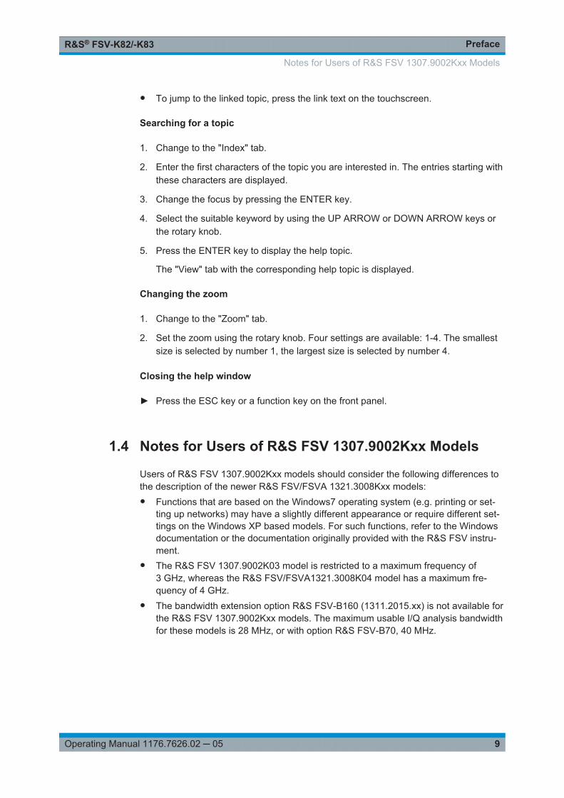
Risk of damage to the instrumentBefore taking the instrument into operation, make sure that● the housing covers are in place and their screws have been tightened,● the ventilation slits are free,● no signal voltage levels above the permissible limits are applied to the inputs,● the outputs of the unit are not overloaded or wrongly connected.
Failure to comply may result in damage to the instrument
Connect the antenna output (or TX output) of the base station to the RF input of theR&S FSV/FSVA. Use a power attenuator exhibiting suitable attenuation.
The following values for external attenuation are recommended to ensure that the RFinput of the analyzer is protected and the sensitivity of the unit is not reduced toomuch:
Maximum Power Recommended external attenuation
≥ 55 to 60 dBm 35 to 40 dB
≥ 50 to 55 dBm 30 to 35 dB
≥ 45 to 50 dBm 25 to 30 dB
≥ 40 to 45 dBm 20 to 25 dB
≥ 35 to 40 dBm 15 to 20 dB
≥ 30 to 35 dBm 10 to 15 dB
≥ 25 to 30 dBm 0 to 10 dB
≥ 20 to 25 dBm 0 to 5 dB
20 dBm 0 dB
● For signal measurements at the output of two-port networks, connect the referencefrequency of the signal source to the rear reference input of the analyzer.
● The R&S FSV/FSVA must be operated with an external frequency reference toensure that the error limits of the CDMA2000 specification for frequency measure-ments on base stations are met. A rubidium frequency standard can be used as areference source for example.
● If the base station has a trigger output, connect the trigger output of the base sta-tion to the rear trigger input of the analyzer (EXT TRIG GATE).
Presettings
● Enter the external attenuation.● Enter the reference level.● Enter the center frequency.● Set the trigger.
Test Setup for Base Station Tests

Measurement Examples for the CDMA2000 BTS Analysis (option K82)R&S® FSV-K82/-K83
15Operating Manual 1176.7626.02 ─ 05
● If used, enable the external reference.● Select the standard and the desired measurement.● Set the PN offset.
4.2 Measuring the Signal Channel Power
In the Power measurement, the total channel power of the CDMA2000 signal is dis-played. The measurement also displays spurious emissions like harmonics or intermo-dulation products that occur close to the carrier.
Test setup:
● Connect the RF output of the signal generator to the RF input of the R&S FSV/FSVA (coaxial cable with N connectors).
Signal generator settings:
Frequency: 878.49 MHz
Level: 0 dBm
Standard: CDMA2000
Procedure:
1. Set the R&S FSV/FSVA to its default state.
a) Press the PRESET key.
2. Press the MODE key and activate the CDMA2000 BTS Analysis option.
3. Start the Power measurement
a) Press the MEAS key.b) Press the "Power" softkey.
4. Set the center frequency to 878.49 MHz.
5. Set the reference level.
a) Press the AMPT key and enter 0 dBm.
On the screen, the spectrum of the signal and the corresponding power levels withinthe 1.2288 MHz channel bandwidth are displayed. In the table below the diagram, thenumeric values of the channel bandwidth of the TX Channel and power level of theanalyzed signal are listed.
4.3 Measuring the Spectrum Emission Mask
To detect spurious emissions such as harmonics or intermodulation products, theR&S FSV/FSVA offers a spectrum emission mask measurement. The measurement
Measuring the Spectrum Emission Mask

Measurement Examples for the CDMA2000 BTS Analysis (option K82)R&S® FSV-K82/-K83
16Operating Manual 1176.7626.02 ─ 05
compares the power against the spectrum emission mask in the range from -4 MHz to4 MHz around the carrier. The exact measurement settings like the filter that is useddepend on the Band Class parameter. For a list of supported bandclasses refer to theBandclass softkey in the "Spectrum Emission Mask" menu.
Test setup:
● Connect the RF output of the signal generator to the RF input of the R&S FSV/FSVA (coaxial cable with N connectors).
Signal generator settings:
● Frequency: 878.49 MHz● Level: 0 dBm● Standard: CDMA2000● Link direction: Downlink
Procedure:
1. Set the R&S FSV/FSVA to its default state.
a) Press the PRESET key.
2. Activate the CDMA2000 BTS Analysis mode.
a) Press the MODE key and activate the CDMA2000 BTS Analysis option.
3. Start the measurement.
a) Press the MEAS key.b) Press the "Spectrum Emission Mask" softkey.
4. Set the center frequency.
a) Press the FREQ key and enter 878.49 MHz.
5. Set the reference level.
a) Press the AMPT key and enter 0 dBm.
6. Select a bandclass
a) Press the "Bandclass" softkey and select "BandClass 0: 800 MHz CellularBand" from the list.
On the screen, the spectrum of the signal is displayed, including the limit line defined inthe standard. To understand where and about how much the measurement has failed,the "List Evaluation" table shows the frequencies where spurious emissions occur.
Measuring the Spectrum Emission Mask

Measurement Examples for the CDMA2000 BTS Analysis (option K82)R&S® FSV-K82/-K83
17Operating Manual 1176.7626.02 ─ 05
4.4 Measuring the Relative Code Domain Power and Fre-quency Error
A Code Domain Power measurement analyses the signal over a single Power ControlGroup (PCG). It also determines the power of all codes and channels.
The following examples show a Code Domain Power measurement on a test modelwith 9 channels. In this measurement, changing some parameters one after the othershould demonstrate the resulting effects: values adapted to the measurement signalare changed to non-adapted values.
In the following examples, adjusting the settings of the code domain measurements isdescribed using the dialog boxes. Alternatively, most of the settings can also be modi-fied by using the corresponding hardkeys as in the base unit (e.g. the center frequencycan be either set in the "Frontend Settings" dialog box, or via the FREQ key).
Test setup:
● Connect the RF output of the signal generator to the RF input of the R&S FSV/FSVA.
● Connect the reference input (EXT REF) on the rear panel of the R&S FSV/FSVA tothe reference output (REF) of the signal generator (coaxial cable with BNC connec-tors).
Signal generator settings:
Frequency: 878.49 MHz
Level: 0 dBm
Standard: CDMA2000
Procedure:
1. Set the R&S FSV/FSVA to its default state.
a) Press the PRESET key.
2. Activate the "CDMA2000 BS Analysis" Mode.
a) Press the MODE key and select "CDMA2000 BS Analysis".
3. Enter the Code Domain Analyzer.
a) Press the MEAS keyb) Press the "Code Domain Analyzer" softkey.
4. Start the measurement
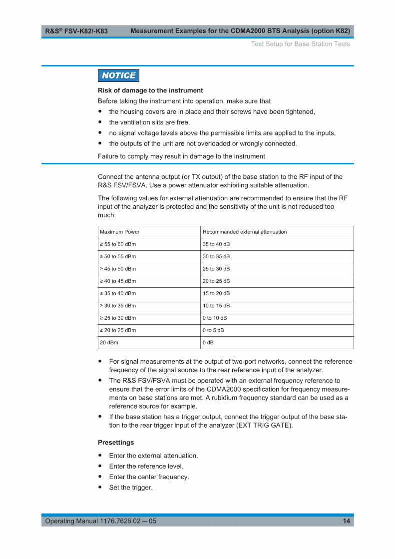
a) In the "Code Domain Analyzer" menu, press the "Display Config" softkey.b) Select the "Code Domain Power" measurement.
5. Set the center frequency and the reference level.
a) In the "Code Domain Analyzer" menu, press the "Frontend Settings" softkey.
Measuring the Relative Code Domain Power and Frequency Error

Measurement Examples for the CDMA2000 BTS Analysis (option K82)R&S® FSV-K82/-K83
18Operating Manual 1176.7626.02 ─ 05
b) In the "Center Frequency" field enter 878.49 MHz.c) In the "Ref Level" field enter 10 dBm.d) Close the "Frontend Settings" dialog box.
In the two screens, the following results are displayed: screen A shows the power ofthe code domain of the signal. The x-axis represents the individual channels (orcodes), while the y-axis shows the power of each channel.
In screen B the result summary is displayed. It shows the numeric results of the codedomain power measurement, including the frequency error.
By default, the R&S FSV-K82 displays two measurement screens. After a presetscreen A is always the Code Domain Power result display. Screen B is always theResult Summary display.For more information on the display concept refer to the Display Config softkey.
Synchronization of the reference frequencies
The frequency error can be reduced by synchronizing the transmitter and the receiverto the same reference frequency.
● Press the SETUP key.– Press the "Reference Int/Ext" softkey to switch to an external reference.
Screen A again shows the Code Domain Power measurement and screen B the resultsummary. After the synchronization of the reference frequencies of the devices, thefrequency error should now be smaller than 10 Hz.
Behavior with deviating center frequency setting
A measurement can only be valid if the center frequency of the DUT and the analyzerare balanced.
1. On the signal generator, change the center frequency in steps of 0.1 kHz andobserve the analyzer screen.Up to a frequency error of approximately 1.0 kHz, a Code Domain Power measure-ment on the R&S FSV/FSVA is still possible. A frequency error within this rangecauses no apparent difference in the accuracy of the Code Domain Power mea-surement.In case of a frequency error of more than 1.0 kHz, the probability of incorrect syn-chronization increases. This is indicated by the "SYNC FAILED" error message.If the frequency error exceeds approximately 1.5 kHz, a Code Domain Power mea-surement cannot be performed. This is also indicated by the "SYNC FAILED" errormessage.
2. Reset the center frequency of the signal generator to 878.49 MHz.
Measuring the Relative Code Domain Power and Frequency Error

Measurement Examples for the CDMA2000 BTS Analysis (option K82)R&S® FSV-K82/-K83
19Operating Manual 1176.7626.02 ─ 05
The center frequency of the DUT should not deviate by more than 1.0 kHz from that ofthe R&S FSV/FSVA.
4.5 Measuring the Triggered Relative Code DomainPower
If the code domain power measurement is performed without external triggering, a sec-tion of the test signal is recorded at an arbitrary point of time and the firmware attemptsto detect the start of a PCG. To detect this start, all possibilities of the PN sequencelocation have to be tested in Free Run trigger mode. This requires computing time.This computing time can be reduced by using an external (frame) trigger and enteringthe correct PN offset. If the search range for the start of the power control group andthe PN offset are known then fewer possibilities have to be tested. This increases themeasurement speed.
Test setup:
● Connect the RF output of the signal generator to the input of the R&S FSV/FSVA.● Connect the reference input (EXT REF) on the rear panel of the R&S FSV/FSVA to
the reference input of the signal generator (coaxial cable with BNC connectors).● Connect the external trigger input on the rear panel of the R&S FSV/FSVA (EXT
TRIGGER/GATE IN) to the external trigger output of the signal generator.
Signal generator settings:
● Frequency: 878.49 MHz● Level: 0 dBm● Standard: CDMA2000● Link direction: Downlink
Procedure:
1. Set the R&S FSV/FSVA to its default state.
a) Press the PRESET key.
2. Activate the CDMA2000 BTS Analysis Mode.
a) Press the MODE key and select CDMA2000 BS Analysis.
3. Enter the Code Domain Analyzer.
a) Press the MEAS keyb) Press the "Code Domain Analyzer" softkey.
4. Start the measurement.
a) In the "Code Domain Analyzer" menu, press the "Display Config" softkey.b) Select the tab for Screen A.
Measuring the Triggered Relative Code Domain Power
Measurement Examples for the CDMA2000 BTS Analysis (option K82)R&S® FSV-K82/-K83
20Operating Manual 1176.7626.02 ─ 05
c) Select the "Code Domain Power" measurement.
5. Set the center frequency and the reference level.
a) In the "Code Domain Analyzer" menu, press the "Frontend Settings" softkey.b) In the "Center Frequency" field enter 878.49 MHz.c) In the "Ref Level" field enter 10 dBm.d) Close the "Frontend Settings" dialog box.
In the two screens, the following results are displayed: by default, screen A shows thecode domain power of the signal. Compared to the measurement without an externaltrigger (see previous example), the repetition rate of the measurement increases. Inscreen B the result summary is displayed. In the row Trigger to Frame, the offsetbetween the trigger event and and the start of the PCG is shown.
4.5.1 Adjusting the Trigger Offset
The delay between the trigger event and the start of the PCG can be compensated forby adjusting the trigger offset.
Set an external trigger source and the trigger offset.
1. Open the "IQ Capture" dialog box.
2. Set the "Trigger Source" option to "External".
3. Set the "Trigger Offset" to 100µs to compensate analog delays of the trigger event.
In the two screens, the following results are displayed: Screen A shows the the sameas above. In screen B the result summary is displayed. In the "Trg to Frame" result, theoffset between the trigger event and the start of the PCG has been adjusted.
4.5.2 Behaviour With the Wrong PN Offset
The last adjustment is setting the PN (Pseudo Noise) offset correctly. The measure-ment is only valid if the PN offset on the analyzer is the same as that of the transmitsignal.
● Set a PN Offset.– Open the "Demodulation Settings" dialog box.– In the "PN Offset" field enter 200.
Again, screen A shows the CDP measurement, screen B the result summary. In theresult summary, the "Trigger to Frame" result is not correct. Also, the error message"SYNC FAILED" indicates that the synchronization has failed.
► In the "PN Offset" field enter 0:
After adjusting it, the PN offset on the R&S FSV/FSVA is the same as that of the sig-nal. In the result summary the "Trg To Frame" value is now shown correctly.
Measuring the Triggered Relative Code Domain Power

Measurement Examples for the CDMA2000 BTS Analysis (option K82)R&S® FSV-K82/-K83
21Operating Manual 1176.7626.02 ─ 05
4.6 Measuring the Composite EVM
The Error Vector Magnitude (EVM) describes the quality of the measured signal com-pared to an ideal reference signal generated by the R&S FSV/FSVA. In the I-Q plane,the error vector represents the ratio of the measured signal to the ideal signal on sym-bol level. The error vector is equal to the square root of the ratio of the measured sig-nal to the reference signal. The result is given in %.
In the Composite EVM measurement the error is averaged over all channels (bymeans of the root mean square) for a given PCG. The measurement covers the entiresignal during the entire observation time. On screen the results are shown in a dia-gram, in which the x-axis represents the examined PCGs and the y-axis shows theEVM values.
Test Setup:
● Connect the RF output of the signal generator to the RF input of the R&S FSV/FSVA. (coaxial cables with N connectors).
● Connect the reference input (EXT REF IN/OUT) on the rear panel of the R&S FSV/FSVA.L to the reference output (REF) on the signal generator (coaxial cable withBNC connectors).
● Connect external triggering of the analyzer (EXT TRIG GATE) to the signal genera-tor’s trigger (TRIGOUT1 at PAR DATA).
Signal generator settings:
● Frequency: 878.49 MHz● Level: 0 dBm● Standard: CDMA2000● Link direction: Downlink
Procedure:
1. Set the R&S FSV/FSVA to its default state.
a) Press the PRESET key.
2. Activate the CDMA2000 BTS Analysis Mode.
a) Press the MODE key and select CDMA2000 BTS Analysis.
3. Enter the Code Domain Analyzer.
a) Press the MEAS keyb) Press the "Code Domain Analyzer" softkey.
4. Start the measurement.
a) Press the "Display Config" softkey.b) Select the tab for Screen A.c) Select the "Composite EVM" measurement.
5. Set the center frequency and the reference level.
Measuring the Composite EVM

Measurement Examples for the CDMA2000 BTS Analysis (option K82)R&S® FSV-K82/-K83
22Operating Manual 1176.7626.02 ─ 05
a) Open the "Frontend Settings" dialog box.b) In the "Center Frequency" field enter 878.49 MHz.c) In the "Ref Level" field enter 10 dBm.d) Close the "Frontend Settings" dialog box.
6. Set an external trigger source.
a) Open the "IQ Capture Settings" dialog box.b) Set the "Trigger Source" option to "External".
In the two screens, the following results are displayed: by default, Screen A shows thediagram of the Composite EVM measurement result. In screen B the result summary isdisplayed. It shows the numeric results of the Code Domain Power measurement,including the values for the Composite EVM.
4.7 Measuring the Peak Code Domain Error and the RHOFactor
The Code Domain Error Power describes the quality of the measured signal comparedto an ideal reference signal generated by the R&S FSV/FSVA. In the I-Q plane, theerror vector represents the difference of the measured signal and the ideal signal. TheCode Domain Error is the difference in power on symbol level of the measured and thereference signal projected to the class of of the base spreading factor. The unit of theresult is dB.
In the Peak Code Domain Error (PCDE) measurement, the maximum error value overall channels is determined and displayed for a given PCG. The measurement coversthe entire signal during the entire observation time. On screen the results are shown ina diagram, in which the x-axis represents the PCGs and the y-axis shows the PCDEvalues.
A measurement of the RHO factor is shown in the second part of the example. RHO isthe normalized, correlated power between the measured and the ideal reference sig-nal. The maximum value of RHO is 1. In that case the measured signal and the refer-ence signal are identical. When measuring RHO, it is required that only the pilot chan-nel is active.
Test setup:
● Connect the RF output of the signal generator to the RF input of the R&S FSV/FSVA (coaxial cable with N connectors).
● Connect the reference input (EXT REF IN/OUT) on the rear panel of the R&S FSV/FSVA to the reference output (REF) on the signal generator (coaxial cable withBNC connectors).
● Connect external triggering of the R&S FSV/FSVA (EXT TRIG GATE) to the signalgenerator trigger (TRIGOUT1 at PAR DATA).
Measuring the Peak Code Domain Error and the RHO Factor

Measurement Examples for the CDMA2000 BTS Analysis (option K82)R&S® FSV-K82/-K83
23Operating Manual 1176.7626.02 ─ 05
Signal generator settings:
● Frequency: 878.49 MHz● Level: 0 dBm● Standard: CDMA2000● Link direction: Downlink
Procedure:
1. Set the R&S FSV/FSVA to its default state.
a) Press the PRESET key.
2. Activate the CDMA2000 BTS Analysis Mode.
a) Press the MODE key and activate the CDMA2000 BTS Analysis option.
3. Enter the Code Domain Analyzer.
a) Press the MEAS key.b) Press the "Code Domain Analyzer" softkey.
4. Start the Peak Code Domain Error measurement.
a) Press the "Display Config" softkeyb) Select the tab for Screen A.c) Select the "Peak Code Domain Error" softkey and start the measurement.
5. Set the center frequency and the reference level.
a) Open the "Frontend Settings" dialog box.b) In the "Center Frequency" field enter 878.49 MHz.c) In the "Ref Level" field enter 0 dBm.d) Close the "Frontend Settings" dialog box.
6. Set an external trigger source.
a) Open the "IQ Capture Settings" dialog box.b) Set the "Trigger Source" option to "External".
In the two screens, the following results are displayed: by default, screen A shows thediagram of the Peak Code Domain Error. In screen B the result summary is displayed.
Displaying RHO
Make sure that all channels except the pilot channel (code 0.64) are OFF, so that onlythe pilot channel is available in the measurement.
No specific measurement is required to get the value for RHO. The R&S FSV/FSVAalways calculates this value automatically regardless of the code domain measurementperformed. Besides the results of the code domain measurements, the numeric resultof the RHO measurement is shown in the result summary, by default shown in screenB.
Measuring the Peak Code Domain Error and the RHO Factor

Measurement Examples for the CDMA2000 MS Analysis (option K83)R&S® FSV-K82/-K83
24Operating Manual 1176.7626.02 ─ 05
5 Measurement Examples for the CDMA2000MS Analysis (option K83)This section explains basic CDMA2000 mobile station tests using a setup with a signalgenerator, e.g. an R&S SMU. It describes how operating and measurement errors canbe avoided using correct settings. The measurements are performed with anR&S FSV/FSVA equipped with the CDMA2000 MS Analysis option (K83).
As the CDMA2000 MS Analysis option also supports the CDMA2000 Standard, theexamples are performed on a CDMA2000 signal.
General Test Setup
The measurements are performed with the following units and accessories:
● An R&S FSV/FSVA equipped with the CDMA2000 MS Analysis option.● R&S SMU signal generator equipped with option SMU-B9/B10/B11 baseband gen-
erator and SMUK46 CDMA2000 incl. 1xEVDV.● 1 coaxial cable, 50 Ω, approximately 1 m, N connector● 2 coaxial cables, 50 Ω, approximately 1 m, BNC connector
● Test Setup for Base Station or Mobile Station Tests.............................................. 24● Measuring the Signal Channel Power.....................................................................26● Measuring the Spectrum Emission Mask................................................................27● Measuring the Relative Code Domain Power and Frequency Error....................... 28● Measuring the Triggered Relative Code Domain Power.........................................30● Measuring the Composite EVM.............................................................................. 31● Measuring the Peak Code Domain Error and the RHO Factor...............................33
5.1 Test Setup for Base Station or Mobile Station Tests
This section describes the default settings of the R&S FSV/FSVA, if it is used as aCDMA2000 base or mobile station tester. Before starting the measurements, theR&S FSV/FSVA has to be configured correctly and supplied with power as describedin the Quick Start Guide, "Preparing For Use". Furthermore, the application firmware ofthe R&S FSV-K82 (base station) or -K83 (mobile station) must be enabled. Installationand enabling of the application firmware are described in the Quick Start Guide.
Test Setup for Base Station or Mobile Station Tests

Measurement Examples for the CDMA2000 MS Analysis (option K83)R&S® FSV-K82/-K83
25Operating Manual 1176.7626.02 ─ 05
Risk of instrument damage during operationAn unsuitable operating site or test setup can cause damage to the instrument and toconnected devices. Ensure the following operating conditions before you switch on theinstrument:● All fan openings are unobstructed and the airflow perforations are unimpeded. The
minimum distance from the wall is 10 cm.● The instrument is dry and shows no sign of condensation.● The instrument is positioned as described in the following sections.● The ambient temperature does not exceed the range specified in the data sheet.● Signal levels at the input connectors are all within the specified ranges.● Signal outputs are correctly connected and are not overloaded.
Connect the antenna output (or TX output) of the base station/mobile station to the RFinput of the R&S FSV/FSVA. Use a power attenuator exhibiting suitable attenuation.
2DEF 3GHI1ABC5 64
8ÜVW7STU. -0
9XYZ
S CRCL M
RF INPUT
TX signal
The following values for external attenuation are recommended to ensure that the RFinput of the analyzer is protected and the sensitivity of the unit is not reduced toomuch:
Maximum Power Recommended external attenuation
≥ 55 to 60 dBm 35 to 40 dB
≥ 50 to 55 dBm 30 to 35 dB
≥ 45 to 50 dBm 25 to 30 dB
≥ 40 to 45 dBm 20 to 25 dB
≥ 35 to 40 dBm 15 to 20 dB
≥ 30 to 35 dBm 10 to 15 dB
≥ 25 to 30 dBm 0 to 10 dB
≥ 20 to 25 dBm 0 to 5 dB
≤ 20 dBm 0 dB
Test Setup for Base Station or Mobile Station Tests
Measurement Examples for the CDMA2000 MS Analysis (option K83)R&S® FSV-K82/-K83
26Operating Manual 1176.7626.02 ─ 05
● For signal measurements at the output of two-port networks, connect the referencefrequency of the signal source to the rear reference input of the analyzer.
● The R&S FSV/FSVA must be operated with an external frequency reference toensure that the error limits of the CDMA2000 specification for frequency measure-ments on base stations/mobile stations are met. A rubidium frequency standardcan be used as a reference source for example.
● If the base station/mobile station has a trigger output, connect the trigger output ofthe base station/mobile station to the rear trigger input of the analyzer (EXT TRIGGATE).
Presettings
● Enter the external attenuation.● Enter the reference level.● Enter the center frequency.● Set the trigger.● If used, enable the external reference.● Select the standard and the desired measurement.● Set the PN offset.
5.2 Measuring the Signal Channel Power
In the Power measurement, the total channel power of the CDMA2000 signal is dis-played. The measurement also displays spurious emissions like harmonics or intermo-dulation products that occur close to the carrier.
Test setup:
● Connect the RF output of the signal generator to the RF input of the R&S FSV/FSVA (coaxial cable with N connectors).
Signal generator settings:
● Frequency: 833.49 MHz● Level: 0 dBm● Standard: CDMA2000● Link direction: Uplink
Procedure:
1. Set the R&S FSV/FSVA to its default state.
a) Press the PRESET key.
2. Press the MODE key and activate the CDMA2000 MS Analysis option.
3. Start the Power measurement
Measuring the Signal Channel Power

Measurement Examples for the CDMA2000 MS Analysis (option K83)R&S® FSV-K82/-K83
27Operating Manual 1176.7626.02 ─ 05
a) Press the MEAS key.b) Press the "Power" softkey.
4. Set the center frequency to 833.49 MHz.
5. Set the reference level.
a) Press the AMPT key and enter 0 dBm.
On the screen, the spectrum of the signal and the corresponding power levels withinthe 1.2288 MHz channel bandwidth are displayed. In the table below the diagram, thenumeric values of the channel bandwidth of the TX Channel and power level of theanalyzed signal are listed.
5.3 Measuring the Spectrum Emission Mask
To detect spurious emissions such as harmonics or intermodulation products, theR&S FSV/FSVA offers a spectrum emission mask measurement. The measurementcompares the power against the spectrum emission mask in the range from -4 MHz to4 MHz around the carrier. The exact measurement settings like the filter that is useddepend on the Band Class parameter. For a list of supported bandclasses refer to theBandclass softkey in the "Spectrum Emission Mask" menu.
Test setup:
● Connect the RF output of the signal generator to the RF input of the R&S FSV/FSVA (coaxial cable with N connectors).
Signal generator settings:
● Frequency: 833.49 MHz● Level: 0 dBm● Standard: CDMA2000● Link direction: Uplink
Procedure:
1. Set the R&S FSV/FSVA to its default state.
a) Press the PRESET key.
2. Activate the "CDMA2000 MS Analysis" mode.
a) Press the MODE key and activate the "CDMA2000 MS Analysis" option.
3. Start the measurement.
a) Press the MEAS key.b) Press the "Spectrum Emission Mask" softkey.
4. Set the center frequency.
a) Press the FREQ key and enter 878.49 MHz.
Measuring the Spectrum Emission Mask

Measurement Examples for the CDMA2000 MS Analysis (option K83)R&S® FSV-K82/-K83
28Operating Manual 1176.7626.02 ─ 05
5. Set the reference level.
a) Press the AMPT key and enter 0 dBm.
6. Select a bandclass
a) Press the "Bandclass" softkey and select BandClass 0: 800 MHz Cellular Bandfrom the list.
On the screen, the spectrum of the signal is displayed, including the limit line defined inthe standard. To understand where and about how much the measurement has failed,the "List Evaluation" table shows the frequencies where spurious emissions occur.
5.4 Measuring the Relative Code Domain Power and Fre-quency Error
A Code Domain Power measurement analyses the signal over a single Power ControlGroup (PCG). It also determines the power of all codes and channels.
The following examples show a Code Domain Power measurement on a test modelwith 9 channels. In this measurement, changing some parameters one after the othershould demonstrate the resulting effects: values adapted to the measurement signalare changed to non-adapted values.
In the following examples, adjusting the settings of the code domain measurements isdescribed using the dialog boxes. Alternatively, most of the settings can also be modi-fied by using the corresponding hardkeys as in the base unit (e.g. the center frequencycan be either set in the "Frontend Settings" dialog box, or via the FREQ key).
Test setup:
● Connect the RF output of the signal generator to the RF input of the R&S FSV/FSVA.
● Connect the reference input (EXT REF) on the rear panel of the R&S FSV/FSVA tothe reference output (REF) of the signal generator (coaxial cable with BNC connec-tors).
Signal generator settings:
Frequency: 833.49 MHz
Level: 0 dBm
Standard: CDMA2000
Procedure:
1. Set the R&S FSV/FSVA to its default state.
a) Press the PRESET key.
Measuring the Relative Code Domain Power and Frequency Error

Measurement Examples for the CDMA2000 MS Analysis (option K83)R&S® FSV-K82/-K83
29Operating Manual 1176.7626.02 ─ 05
2. Activate the "CDMA2000 BS Analysis" Mode.
a) Press the MODE key and select "CDMA2000 BS Analysis".
3. Enter the Code Domain Analyzer.
a) Press the MEAS keyb) Press the "Code Domain Analyzer" softkey.
4. Start the measurement
a) In the "Code Domain Analyzer" menu, press the "Display Config" softkey.b) Select the "Code Domain Power" measurement.
5. Set the center frequency and the reference level.
a) In the "Code Domain Analyzer" menu, press the "Frontend Settings" softkey.b) In the "Center Frequency" field enter 833.49 MHz.c) In the "Ref Level" field enter 10 dBm.d) Close the "Frontend Settings" dialog box.
In the two screens, the following results are displayed: screen A shows the power ofthe code domain of the signal. The x-axis represents the individual channels (orcodes), while the y-axis shows the power of each channel.
In screen B the result summary is displayed. It shows the numeric results of the codedomain power measurement, including the frequency error.
By default, the R&S FSV-K83 displays two measurement screens. After a presetscreen A is always the "Code Domain Power" result display. Screen B is always the"Result Summary" display.For more information on the display concept refer to Chapter 6.1.1, "Display Concept",on page 36.
Synchronization of the reference frequencies
The frequency error can be reduced by synchronizing the transmitter and the receiverto the same reference frequency.
● Press the SETUP key.– Press the "Reference Int/Ext" softkey to switch to an external reference.
Screen A again shows the Code Domain Power measurement and screen B the resultsummary. After the synchronization of the reference frequencies of the devices, thefrequency error should now be smaller than 10 Hz.
Behavior with deviating center frequency setting
A measurement can only be valid if the center frequency of the DUT and the analyzerare balanced.
1. On the signal generator, change the center frequency in steps of 0.1 kHz andobserve the analyzer screen.
Measuring the Relative Code Domain Power and Frequency Error

Measurement Examples for the CDMA2000 MS Analysis (option K83)R&S® FSV-K82/-K83
30Operating Manual 1176.7626.02 ─ 05
Up to a frequency error of approximately 1.0 kHz, a Code Domain Power measure-ment on the R&S FSV/FSVA is still possible. A frequency error within this rangecauses no apparent difference in the accuracy of the Code Domain Power mea-surement.In case of a frequency error of more than 1.0 kHz, the probability of incorrect syn-chronization increases. This is indicated by the "SYNC FAILED" error message.If the frequency error exceeds approximately 1.5 kHz, a Code Domain Power mea-surement cannot be performed. This is also indicated by the "SYNC FAILED" errormessage.
2. Reset the center frequency of the signal generator to 833.49 MHz.
The center frequency of the DUT should not deviate by more than 1.0 kHz from that ofthe R&S FSV/FSVA.
5.5 Measuring the Triggered Relative Code DomainPower
If the code domain power measurement is performed without external triggering, a sec-tion of the test signal is recorded at an arbitrary point of time and the firmware attemptsto detect the start of a PCG. To detect this start, all possibilities of the PN sequencelocation have to be tested in Free Run trigger mode. This requires computing time.This computing time can be reduced by using an external (frame) trigger and enteringthe correct PN offset. If the search range for the start of the power control group andthe PN offset are known then fewer possibilities have to be tested. This increases themeasurement speed.
Test setup:
● Connect the RF output of the signal generator to the input of the R&S FSV/FSVA.● Connect the reference input (EXT REF) on the rear panel of the R&S FSV/FSVA to
the reference input of the signal generator (coaxial cable with BNC connectors).● Connect the external trigger input on the rear panel of the R&S FSV/FSVA (EXT
TRIGGER/GATE IN) to the external trigger output of the signal generator.
Signal generator settings:
● Frequency: 833.49 MHz● Level: 0 dBm● Standard: CDMA2000● Link direction: Uplink
Procedure:
1. Set the R&S FSV/FSVA to its default state.
Measuring the Triggered Relative Code Domain Power

Measurement Examples for the CDMA2000 MS Analysis (option K83)R&S® FSV-K82/-K83
31Operating Manual 1176.7626.02 ─ 05
a) Press the PRESET key.
2. Activate the "CDMA2000 MS Analysis" Mode.
a) Press the MODE key and select CDMA2000 BS Analysis.
3. Enter the Code Domain Analyzer.
a) Press the MEAS keyb) Press the "Code Domain Analyzer" softkey.
4. Start the measurement.
a) In the "Code Domain Analyzer" menu, press the "Display Config" softkey.b) Select the tab for Screen A.c) Select the "Code Domain Power" measurement.
5. Set the center frequency and the reference level.
a) In the "Code Domain Analyzer" menu, press the "Frontend Settings" softkey.b) In the "Center Frequency" field enter 833.49 MHz.c) In the "Ref Level" field enter 10 dBm.d) Close the "Frontend Settings" dialog box.
In the two screens, the following results are displayed: by default, screen A shows thecode domain power of the signal. Compared to the measurement without an externaltrigger (see previous example), the repetition rate of the measurement increases. Inscreen B the result summary is displayed. In the row Trigger to Frame, the offsetbetween the trigger event and and the start of the PCG is shown.
5.5.1 Adjusting the Trigger Offset
The delay between the trigger event and the start of the PCG can be compensated forby adjusting the trigger offset.
Set an external trigger source and the trigger offset.
1. Open the "IQ Capture" dialog box.
2. Set the "Trigger Source" option to "External".
3. Set the "Trigger Offset" to 100µs to compensate analog delays of the trigger event.
In the two screens, the following results are displayed: Screen A shows the the sameas above. In screen B the result summary is displayed. In the "Trg to Frame" result, theoffset between the trigger event and the start of the PCG has been adjusted.
5.6 Measuring the Composite EVM
The Error Vector Magnitude (EVM) describes the quality of the measured signal com-pared to an ideal reference signal generated by the R&S FSV/FSVA. In the I-Q plane,the error vector represents the ratio of the measured signal to the ideal signal on sym-
Measuring the Composite EVM

Measurement Examples for the CDMA2000 MS Analysis (option K83)R&S® FSV-K82/-K83
32Operating Manual 1176.7626.02 ─ 05
bol level. The error vector is equal to the square root of the ratio of the measured sig-nal to the reference signal. The result is given in %.
In the Composite EVM measurement the error is averaged over all channels (bymeans of the root mean square) for a given PCG. The measurement covers the entiresignal during the entire observation time. On screen the results are shown in a dia-gram, in which the x-axis represents the examined PCGs and the y-axis shows theEVM values.
Test Setup:
● Connect the RF output of the signal generator to the RF input of the R&S FSV/FSVA. (coaxial cables with N connectors).
● Connect the reference input (EXT REF IN/OUT) on the rear panel of the R&S FSV/FSVA.L to the reference output (REF) on the signal generator (coaxial cable withBNC connectors).
● Connect external triggering of the analyzer (EXT TRIG GATE) to the signal genera-tor’s trigger (TRIGOUT1 at PAR DATA).
Signal generator settings:
● Frequency: 833.49 MHz● Level: 0 dBm● Standard: CDMA2000● Link direction: Uplink
Procedure:
1. Set the R&S FSV/FSVA to its default state.
a) Press the PRESET key.
2. Activate the "CDMA2000 MS Analysis" Mode.
a) Press the MODE key and select "CDMA2000 MS Analysis".
3. Enter the Code Domain Analyzer.
a) Press the MEAS keyb) Press the "Code Domain Analyzer" softkey.
4. Start the measurement.
a) Press the "Display Config" softkey.b) Select the tab for Screen A.c) Select the "Composite EVM" measurement.
5. Set the center frequency and the reference level.
a) Open the "Frontend Settings" dialog box.b) In the "Center Frequency" field enter 833.49 MHz.c) In the "Ref Level" field enter 10 dBm.d) Close the "Frontend Settings" dialog box.
Measuring the Composite EVM
Measurement Examples for the CDMA2000 MS Analysis (option K83)R&S® FSV-K82/-K83
33Operating Manual 1176.7626.02 ─ 05
6. Set an external trigger source.
a) Open the "IQ Capture Settings" dialog box.b) Set the "Trigger Source" option to "External".
In the two screens, the following results are displayed: by default, Screen A shows thediagram of the Composite EVM measurement result. In screen B the result summary isdisplayed. It shows the numeric results of the Code Domain Power measurement,including the values for the Composite EVM.
5.7 Measuring the Peak Code Domain Error and the RHOFactor
The Code Domain Error Power describes the quality of the measured signal comparedto an ideal reference signal generated by the R&S FSV/FSVA. In the I-Q plane, theerror vector represents the difference of the measured signal and the ideal signal. TheCode Domain Error is the difference in power on symbol level of the measured and thereference signal projected to the class of of the base spreading factor. The unit of theresult is dB.
In the Peak Code Domain Error (PCDE) measurement, the maximum error value overall channels is determined and displayed for a given PCG. The measurement coversthe entire signal during the entire observation time. On screen the results are shown ina diagram, in which the x-axis represents the PCGs and the y-axis shows the PCDEvalues.
A measurement of the RHO factor is shown in the second part of the example. RHO isthe normalized, correlated power between the measured and the ideal reference sig-nal. The maximum value of RHO is 1. In that case the measured signal and the refer-ence signal are identical. When measuring RHO, it is required that only the pilot chan-nel is active.
Test setup:
● Connect the RF output of the signal generator to the RF input of the R&S FSV/FSVA (coaxial cable with N connectors).
● Connect the reference input (EXT REF IN/OUT) on the rear panel of the R&S FSV/FSVA to the reference output (REF) on the signal generator (coaxial cable withBNC connectors).
● Connect external triggering of the R&S FSV/FSVA (EXT TRIG GATE) to the signalgenerator trigger (TRIGOUT1 at PAR DATA).
Signal generator settings:
● Frequency: 833.49 MHz● Level: 0 dBm● Standard: CDMA2000● Link direction: Uplink
Measuring the Peak Code Domain Error and the RHO Factor
Measurement Examples for the CDMA2000 MS Analysis (option K83)R&S® FSV-K82/-K83
34Operating Manual 1176.7626.02 ─ 05
Procedure:
1. Set the R&S FSV/FSVA to its default state.
a) Press the PRESET key.
2. Activate the "CDMA2000 MS Analysis" Mode.
a) Press the MODE key and activate the "CDMA2000 MS Analysis" option.
3. Enter the Code Domain Analyzer.
a) Press the MEAS key.b) Press the "Code Domain Analyzer" softkey.
4. Start the Peak Code Domain Error measurement.
a) Press the "Display Config" softkeyb) Select the tab for Screen A.c) Select the "Peak Code Domain Error" option and start the measurement.
5. Set the center frequency and the reference level.
a) Open the "Frontend Settings" dialog box.b) In the "Center Frequency" field enter 833.49 MHz.c) In the "Ref Level" field enter 0 dBm.d) Close the "Frontend Settings" dialog box.
6. Set an external trigger source.
a) Open the "IQ Capture Settings" dialog box.b) Set the "Trigger Source" option to "External".
In the two screens, the following results are displayed: by default, screen A shows thediagram of the Peak Code Domain Error. In screen B the result summary is displayed.
Displaying RHO
Make sure that all channels except the pilot channel (code 0.64) are OFF, so that onlythe pilot channel is available in the measurement.
No specific measurement is required to get the value for RHO. The R&S FSV/FSVAalways calculates this value automatically regardless of the code domain measurementperformed. Besides the results of the code domain measurements, the numeric resultof the RHO measurement is shown in the result summary, by default shown in screenB.
Measuring the Peak Code Domain Error and the RHO Factor

Instrument Functions of the CDMA2000 AnalysisR&S® FSV-K82/-K83
35Operating Manual 1176.7626.02 ─ 05
6 Instrument Functions of the CDMA2000AnalysisThe R&S FSV/FSVA equipped with the CDMA2000 BTS Analysis option performsCode Domain measurements on forward link signals according to the 3GPP2 Standard(Third Generation Partnership Project 2). It is based on the "Recommended MinimumPerformance Standard for CDMA2000 Spread Spectrum Base Stations", C.S0010-Cversion 2.0 dated March 2006. This Standard has been approved by the followingauthority with the specified designation:
● TIA: TIA-97-F-1● TTA: TTAT.3G-C-S0010-C v2.0
When the CDMA2000 specification is mentioned in the document, these standards aremeant.
The CDMA2000 BTS Analysis option supports the radio configurations 1 to 5, i.e. allradio configurations with a single carrier (1X) are supported. Accordingly, IS95A/B sig-nals conforming to radio configurations 1&2 can be measured with the CDMA2000BTS Analysis option. In addition to the measurements called for by the CDMA2000standard in the code domain, the CDMA2000 BTS Analysis option features measure-ments in the spectral range such as channel power, adjacent channel power, occupiedbandwidth and spectrum emission mask with predefined settings.
To open the CDMA2000 settings menu
● Press the MODE key and select the required "CDMA2000" option.● If the required "CDMA2000" Mode is already active, press the HOME key.
The CDMA2000 menu is displayed, which is identical to the "Measurement" menu.
For details on the measurement types, see Chapter 6.1, "Measurements and ResultDisplays", on page 35.
● Measurements and Result Displays........................................................................35● Menu and Softkey Description for CDA Measurements..........................................57● Softkeys and Menus for RF Measurements (K82)..................................................97● Further Information................................................................................................151
6.1 Measurements and Result Displays
The CDMA2000 Analysis options provide the following test measurement types andresult displays. All measurements and result displays are accessed via the"CDMA2000" menu or the MEAS key.
● Display Concept......................................................................................................36● Configuring the Display...........................................................................................37● Code Domain Analysis Results...............................................................................38● RF Measurement Results....................................................................................... 54
Measurements and Result Displays

Instrument Functions of the CDMA2000 AnalysisR&S® FSV-K82/-K83
36Operating Manual 1176.7626.02 ─ 05
6.1.1 Display Concept
Measurement results
The code domain analyzer can show up to four result diagrams in four differentscreens (windows) at one time. For each screen, you can define which type of resultdiagram is to be displayed, or deactivate the screen temporarily. The current configura-tion of the display, i.e. which screens are displayed and which result diagram is dis-played in which screen, can be stored and retrieved later. Thus, you can easily switchbetween predefined display configurations.
The available measurement results are described in the following sections.
All results are calculated from the same dataset of the recorded signal. Thus, it is notnecessary to restart the measurement in order to switch the display mode.
Measurement settings
The most important measurement settings are displayed in the diagram header. ForCode Domain Analyzer measurements, the following settings are shown:
Label Description
Ref level Reference level defined in "Ref Level" on page 62
Freq Center frequency defined in "Center" on page 62
Att Attenuation
Channel Channel with spreading factor
PCG Slot
Power Ref Reference used for power results
SymbRate Symbol rate of the current channel
Overview of all measurement settingsYou can easily display an overview of all measurement settings using the SettingsOverview softkey.
In addition to the information in the diagram header, each screen title contains dia-gram-specific trace information.
Screen focus
One of the screens has a blue frame indicating the focus. The screen focus can bechanged just like in the base system. The settings for trace statistics and markers canonly be changed for the focussed screen. Furthermore, the focussed screen can be setto full screen (for details see the R&S FSV/FSVA Quick Start Guide).
Measurements and Result Displays

Instrument Functions of the CDMA2000 AnalysisR&S® FSV-K82/-K83
37Operating Manual 1176.7626.02 ─ 05
6.1.2 Configuring the Display
1. Select the "Display Config" softkey in the "Code Domain Analyzer" menu.
2. Select the tab for the screen you want to configure (A-D).
3. Select the "Screen X active" option to display the selected screen.
Tip: SCPI command: DISPlay[:WINDow<n>]:STATe on page 236
4. Select the required result diagram to be displayed in the selected screen.
Tip: SCPI command: CALCulate<n>:FEED on page 182
5. Press "Close".
To select a predefined display configuration
You can retrieve previously stored display configurations, and thus easily switchbetween different displays of measurement results.
1. Select the "Predefined" tab in the "Display Configuration" dialog box.
The previously stored and default configurations are listed. The current configura-tion is displayed at the top of the dialog box.
2. Select the required set of screen configurations.
3. Press "Apply".
To store the current display configuration
You can store the current display configuration in the list of predefined settings in orderto switch back to it later.
1. Select the current display configuration at the top of the "Display Configuration"dialog box.
2. Click "Add".
The current display configuration is added to the list of predefined settings.
To remove a predefined display configuration
You can remove one of the stored display configurations.
1. Select the display configuration to be removed from the "Predefined" tab of the"Display Configuration" dialog box.
2. Click "Remove".
The selected display configuration is removed from the list of predefined settings.
Measurements and Result Displays
Instrument Functions of the CDMA2000 AnalysisR&S® FSV-K82/-K83
38Operating Manual 1176.7626.02 ─ 05
To restore the default display configurations
You can restore the default set of predefined display configurations.
► In the "Predefined" tab of the "Display Configuration" dialog box, click "Restore".
6.1.3 Code Domain Analysis Results
The Code Domain Analyzer provides the following result display configurations formeasurements in the code domain:
● Code Domain Power...............................................................................................38● Channel Table.........................................................................................................40● Power vs PCG.........................................................................................................41● Result Summary......................................................................................................42● Code Domain Error Power......................................................................................44● Composite EVM (RMS)...........................................................................................45● Peak Code Domain Error........................................................................................46● Channel Constellation.............................................................................................47● EVM vs Symbol.......................................................................................................48● Composite Constellation......................................................................................... 49● Power vs Symbol.................................................................................................... 50● Channel Bitstream...................................................................................................50● Mag Error vs Chip................................................................................................... 52● Phase Error vs Chip................................................................................................52● Symbol Magnitude Error......................................................................................... 53● Symbol Phase Error................................................................................................54
6.1.3.1 Code Domain Power
This result display determines the power of all channels and plots it in a diagram. Thex-axis represents the channel (code) number, which corresponds to the base spread-ing factor. Each bar in the diagram represents one code. The order of the codesdepends on the "Code Order" on page 76. The y-axis is a logarithmic level axis thatshows the power of each channel.
The measurement evaluates the total signal over a single PCG. It supports both Hada-mard and BitReverse code sorting order.
MS mode: the power is calculated only for the selected branch (I or Q).
Measurements and Result Displays

Instrument Functions of the CDMA2000 AnalysisR&S® FSV-K82/-K83
39Operating Manual 1176.7626.02 ─ 05
Figure 6-1: Code Domain Power Result Display in Hadamard code sorting order
Figure 6-2: Code Domain Power Result Display in Hadamard code sorting order
Active and inactive data channels are defined via the "Inactive Channel Threshold"on page 66. The power values of the active and unassigned channels are shown indifferent colors. In addition, codes with alias power can occur. These codes obtainpower components originating either from a spreading factor higher than the basespreading factor or from the own and/or another antenna as a result of transmit diver-sity.
The following colors are defined:
● Red: selected channel (Channel (Code) Number)● Yellow: active channel● Cyan: inactive channel● Light blue: alias power of higher spreading factor● Magenta: alias power as a result of transmit diversity
If codes with alias power are displayed, set the highest base spreading factor availablein the Base Spreading Factor field.It is not recommended to select more detailed result displays (such as "Channel Con-stell") for unassigned or inactive codes, since the results are not valid.
Measurements and Result Displays

Instrument Functions of the CDMA2000 AnalysisR&S® FSV-K82/-K83
40Operating Manual 1176.7626.02 ─ 05
Remote control
In remote control, this display configuration is selected usingCALC:FEED 'XPOW:CDP'; see CALCulate<n>:FEED on page 182.
To query these results, use the command CALC:MARK:FUNC:CDP:RES? CDP orCALC:MARK:FUNC:CDP:RES? CDPR; see CALCulate<n>:MARKer<m>:FUNCtion:CDPower[:BTS]:RESult? on page 184.
6.1.3.2 Channel Table
This result display shows all channels of the signal. The sorting of the channels isaccording to channel type, i.e. special channels like F-PICH, F-SYNC etc. first, thendata channels (CHAN) and last inactive channels (always shown as '---'). Within agroup, channels are sorted according to the spreading factor and then according tocode number, also in ascending order. Within the code number, first active, then inac-tive channels are listed. The selected channel is marked in red. Active and inactivedata channels are defined via the "Inactive Channel Threshold" on page 66.
The Channel Table result display may contain up to 128 entries, corresponding to thehighest base spreading factor of 128.
The measurement evaluates the total signal over a single PCG.
Figure 6-3: Channel Table result display
For the Code Domain Power measurement, the following parameters are determinedfor the channels:
Parameter Description
Channel Type Shows the channel type ('---' for inactive channels)
Walsh Chan.SF Channel number including the spreading factor (in the form <Channel>.<SF>).
Symb Rate/ksps Symbol rate with which the channel is transmitted (9.6 ksps to 307.2 ksps).
RC Radio configuration.
State Status display. Unassigned codes are identified as inactive channels.
Measurements and Result Displays

Instrument Functions of the CDMA2000 AnalysisR&S® FSV-K82/-K83
41Operating Manual 1176.7626.02 ─ 05
Parameter Description
Pwr dBm/Pwr dB Specification of the absolute (dBm) and relative (dB) power of the channel. Relativepowers are either referred to the pilot channel or the total power of the signal.
T Offs/ns and PhOffs/mrad
Timing/phase offset between this channel and the pilot channel (enabled via the"Demod Settings (BTS mode)" on page 70 dialog box.
If enabled, the maximum value of the timing/phase offset is displayed together withthe associated channel in the last two lines. Since the timing/phase offset values ofeach active channel can be either negative or positive, the absolute values are com-pared and the maximum is displayed with the original sign.
Remote control
In remote control, this display configuration is selected usingCALC:FEED 'XTIM:CDP:ERR:CTABle'; see CALCulate<n>:FEED on page 182.
6.1.3.3 Power vs PCG
In this result display, the power of the selected channel is averaged for each measuredPCG and referred to the pilot power of the PCG. Therefore the unit of the y-axis is dB(relative to the Pilot Channel). The result display consists of the number of the PCGs inthe measurement and their respective power value.
MS mode: the power is calculated only for the selected branch (I or Q).
For signals with enabled power control, use the default reference power setting. Fordetails refer to "Power Reference" on page 76.
The measurement evaluates one code channel over the entire period of observation.The selected PCG is displayed red.
You can set the number of PCGs by means of the "Capture Length" on page 64 field.
Figure 6-4: Power vs PCG result display
For measurements in which Antenna Diversity is inactive (OFF) or set to 'Antenna 1',the F-PICH channel is used as reference, while the F-TDPICH channel is used formeasurements in which Antenna Diversity is set to 'Antenna 2'.
Measurements and Result Displays
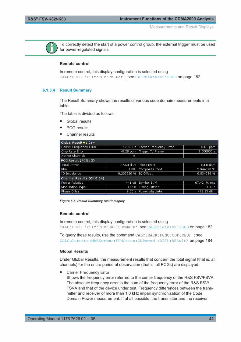
Instrument Functions of the CDMA2000 AnalysisR&S® FSV-K82/-K83
42Operating Manual 1176.7626.02 ─ 05
To correctly detect the start of a power control group, the external trigger must be usedfor power-regulated signals.
Remote control
In remote control, this display configuration is selected usingCALC:FEED 'XTIM:CDP:PVSLot'; see CALCulate<n>:FEED on page 182.
6.1.3.4 Result Summary
The Result Summary shows the results of various code domain measurements in atable.
The table is divided as follows:
● Global results● PCG results● Channel results
Figure 6-5: Result Summary result display
Remote control
In remote control, this display configuration is selected usingCALC:FEED 'XTIM:CDP:ERR:SUMMary'; see CALCulate<n>:FEED on page 182.
To query these results, use the command CALC:MARK:FUNC:CDP:RES? ; seeCALCulate<n>:MARKer<m>:FUNCtion:CDPower[:BTS]:RESult? on page 184.
Global Results
Under Global Results, the measurement results that concern the total signal (that is, allchannels) for the entire period of observation (that is, all PCGs) are displayed:
● Carrier Frequency ErrorShows the frequency error referred to the center frequency of the R&S FSV/FSVA.The absolute frequency error is the sum of the frequency error of the R&S FSV/FSVA and that of the device under test. Frequency differences between the trans-mitter and receiver of more than 1.0 kHz impair synchronization of the CodeDomain Power measurement. If at all possible, the transmitter and the receiver
Measurements and Result Displays

Instrument Functions of the CDMA2000 AnalysisR&S® FSV-K82/-K83
43Operating Manual 1176.7626.02 ─ 05
should be synchronized. For further information on correcting the frequency errorrefer to Chapter 4.4, "Measuring the Relative Code Domain Power and FrequencyError", on page 17 .The frequency error is available in the units both Hz and ppm referred to the carrierfrequency.
● Chip Rate ErrorShows the chip rate error (1.2288 Mcps) in ppm. A large chip rate error results insymbol errors and, therefore, in possible synchronization errors for Code DomainPower measurements. This measurement result is also valid if the R&S FSV/FSVAcould not synchronize to the CDMA2000 signal.
● Trigger to FrameReflects the time offset from the beginning of the recorded signal section to thestart of the first PCG. In case of triggered data recording, this corresponds to thetiming offset:frame trigger (+ trigger offset) – start of first PCGIf it was not possible to synchronize the R&S FSV/FSVA to the CDMA2000 signal,this measurement result is meaningless. For the Free Run trigger mode, dashesare displayed.
● Active ChannelsSpecifies the number of active channels found in the signal. Detected data chan-nels as well as special channels are regarded as active. With transmit diversity, theresult applies to the selected "Antenna Diversity" on page 72. No value is dis-played in both the Min and Max columns.
PCG Results
Under PCG, the measurement results that concern the total signal (that is, all chan-nels) for the selected PCG are displayed:
● Total PowerShows the total power of the signal.
● Pilot PowerShows the power of the pilot channel. If antenna 2 is selected, the power of the F-TDPICH is displayed, in all other cases that of the F-PICH. For details on antennaselection refer to "Antenna Diversity" on page 72.
● RHOShows the quality parameter RHO. According to the CDMA2000 standard, RHO isthe normalized, correlated power between the measured and the ideally generatedreference signal. When RHO is measured, the CDMA2000 standard requires thatonly the pilot channel be supplied.
● Composite EVMThe composite EVM is the difference between the test signal and the ideal refer-ence signal. For further details refer to the Chapter 6.1.3.6, "Composite EVM(RMS)", on page 45 result display.
● IQ Imbalance/OffsetShows the IQ imbalance and the DC offset of the signal in %.
Measurements and Result Displays

Instrument Functions of the CDMA2000 AnalysisR&S® FSV-K82/-K83
44Operating Manual 1176.7626.02 ─ 05
Channel results
Under Channel, the measurement results of the selected channel and the selectedPCG are displayed:
● Power RelativeShows the channel power of the selected channel and PCG. The result dependson the selected Code Power, the Power Reference and absolute channel power.
● Power AbsoluteShows the absolute channel power of the selected channel and PCG
● Timing OffsetShows the timing offset between the selected channel and the pilot channel.
● Phase OffsetShows the phase offset between the selected channel and the pilot channel.
● Symbol EVMShows the peak or mean value of the EVM measurement result. For further detailsrefer to the Chapter 6.1.3.9, "EVM vs Symbol", on page 48 result display.
● ModulationBTS mode only:Displays the modulation type of the channel and PCG: BPSK, QPSK, 8PSK, or16QAM.
● MappingIndicates the selected branch (I or Q)
6.1.3.5 Code Domain Error Power
This result display shows the difference in power of the test signal and an ideally gen-erated reference signal and plots in a diagram. The unit is dB. The x-axis representsthe channel (code) number, which corresponds to the base spreading factor. The y-axis is a logarithmic level axis that shows the error power of each channel. Since it isan error power, active and inactive channels can be rated jointly at a glance.
The measurement evaluates the total signal over a single PCG. It supports both Hada-mard and BitReverse code sorting order.
MS mode: the error power is calculated only for the selected branch (I or Q).
Figure 6-6: Code Domain Error Power result display in Hadamard code sorting order
Measurements and Result Displays

Instrument Functions of the CDMA2000 AnalysisR&S® FSV-K82/-K83
45Operating Manual 1176.7626.02 ─ 05
Figure 6-7: Code Domain Error Power result display in BitReverse code sorting order
Active and inactive data channels are defined via the "Inactive Channel Threshold"on page 66. The power values of the active and inactive channels are shown in dif-ferent colors. In addition, codes with alias power can occur. These codes obtain powercomponents originating either from a spreading factor higher than the base spreadingfactor or from the own and/or another antenna as a result of transmit diversity.
The following colors are defined:
● Red: selected channel (Channel (Code) Number)● Yellow: active channel● Cyan: inactive● Light blue: alias power of higher spreading factor● Magenta: alias power as a result of transmit diversity
If codes with alias power are displayed, set the highest base spreading factor availablein the "Base Spreading Factor" on page 70 field.It is not recommended to select more detailed result displays (such as "Channel Con-stell") for unassigned or inactive codes, since the results are not valid.
Remote control
In remote control, this display configuration is selected usingCALC:FEED 'XPOW:CDEP'; see CALCulate<n>:FEED on page 182.
To query these results, use the command CALC:MARK:FUNC:CDP:RES? ; seeCALCulate<n>:MARKer<m>:FUNCtion:CDPower[:BTS]:RESult? on page 184.
6.1.3.6 Composite EVM (RMS)
This result display is for measuring the modulation accuracy. It determines the errorvector magnitude (EVM) over the total signal. The EVM is the root of the ratio of themean error power (root mean square) to the power of an ideally generated referencesignal. Thus, the EVM is shown in %. The diagram consists of a composite EVM foreach PCG.
Measurements and Result Displays

Instrument Functions of the CDMA2000 AnalysisR&S® FSV-K82/-K83
46Operating Manual 1176.7626.02 ─ 05
The measurement evaluates the total signal over the entire period of observation. Theselected PCG is displayed red. You can set the number of PCGs in the "CaptureLength" on page 64 field.
Figure 6-8: Composite EVM result display
Only the channels detected as being active are used to generate the ideal referencesignal. If a channel is not detected as being active, e.g. on account of low power, thedifference between the test signal and the reference signal and therefore the compo-site EVM is very large. Distortions also occur if unassigned codes are wrongly giventhe status of "active channel". To obtain reliable measurement results, select an ade-quate channel threshold via the "Inactive Channel Threshold" on page 66 field.
Remote control
In remote control, this display configuration is selected usingCALC:FEED 'XTIM:CDP:MACCuracy'; see CALCulate<n>:FEED on page 182.
To query these results, use the command CALC:MARK:FUNC:CDP:RES? MACCuracy; see CALCulate<n>:MARKer<m>:FUNCtion:CDPower[:BTS]:RESult? on page 184.
6.1.3.7 Peak Code Domain Error
The Peak Code Domain Error is defined as the maximum value for the Code DomainError for all codes. That means that in this result display the Code Domain Error Poweris projected onto the code domain at a specific base spreading factor. In the diagram,each bar of the x-axis represents one PCG. The y-axis represents the error power.
You can select the base spreading factor in the "Base Spreading Factor" on page 70field and the number of evaluated PCGs in the "Capture Length" on page 64 field.
The measurement evaluates the total signal over the entire period of observation. Thecurrently selected PCG is displayed red.
MS mode: the error is calculated only for the selected branch (I or Q).
Measurements and Result Displays

Instrument Functions of the CDMA2000 AnalysisR&S® FSV-K82/-K83
47Operating Manual 1176.7626.02 ─ 05
Figure 6-9: Peak Code Domain Error result display
Only the channels detected as being active are used to generate the ideal referencesignal. If a channel is not detected as being active, e.g. on account of low power, thedifference between the test signal and the reference signal is very large. The result dis-play therefore shows a peak code domain error that is too high. Distortions also occurif unassigned codes are wrongly given the status of "active channel". To obtain reliablemeasurement results, select an adequate channel threshold via the "Inactive ChannelThreshold" on page 66 field.
Remote control
In remote control, this display configuration is selected usingCALC:FEED 'XTIM:CDP:ERR:PCDomain'; see CALCulate<n>:FEEDon page 182.
To query these results, use the command CALC:MARK:FUNC:CDP:RES? PCDerror;see CALCulate<n>:MARKer<m>:FUNCtion:CDPower[:BTS]:RESult?on page 184.
6.1.3.8 Channel Constellation
This result display shows the channel constellation of the modulated signal at symbollevel.
The measurement evaluates a single channel over a single PCG.
You can select a specific channel and PCG with the Select softkey.
Measurements and Result Displays

Instrument Functions of the CDMA2000 AnalysisR&S® FSV-K82/-K83
48Operating Manual 1176.7626.02 ─ 05
Figure 6-10: Channel Constellation result display for QPSK-modulated signal
The R&S FSV-K82 supports BPSK, QPSK, 8PSK and 16QAM modulation schemes.The modulation scheme itself depends on the channel type. Refer to Chapter 6.4.1.1,"Relationship Between Channel and Modulation Type", on page 154 for further infor-mation.
In case of BPSK the constellation points are located on the x-axis. For the QPSK and16QAM schemes the constellation points are located on neither axis.
Remote control
In remote control, this display configuration is selected usingCALC:FEED 'XTIM:CDP:SYMB:CONStellation'; see CALCulate<n>:FEEDon page 182.
To query these results, use the command CALC:MARK:FUNC:CDP:RES? ; seeCALCulate<n>:MARKer<m>:FUNCtion:CDPower[:BTS]:RESult? on page 184.
6.1.3.9 EVM vs Symbol
This result display shows the EVM on symbol level. The x-axis represents the symbolsand the y-axis shows the EVM in %.
The measurement evaluates a single channel over a single PCG.
You can select a specific channel and PCG with the "Select" on page 79 softkey.
Figure 6-11: EVM vs Symbol result display
Measurements and Result Displays

Instrument Functions of the CDMA2000 AnalysisR&S® FSV-K82/-K83
49Operating Manual 1176.7626.02 ─ 05
The number of symbols is in the range from 6 to 384 and can be calculated like this:
Number of symbols = Number of chips in one PCG/ChannelSF/K, with
"Number of chips in one PCG = 1536"
"Channel SF = 4, 8, 16, 32, 64 or 128"
"K = 1 for Antenna Diversity = OFF"
"K = 2 for Antenna Diversity = OFF"
This calculation thus takes into account the results of a channel for a power controlgroup.
Inactive channels can be measured, but the result is meaningless since these chan-nels do not contain data.
Remote control
In remote control, this display configuration is selected usingCALC:FEED 'XTIM:CDP:SYMB:EVM'; see CALCulate<n>:FEED on page 182.
To query these results, use the command CALC:MARK:FUNC:CDP:RES? ; seeCALCulate<n>:MARKer<m>:FUNCtion:CDPower[:BTS]:RESult? on page 184.
6.1.3.10 Composite Constellation
This result display shows the constellation of the modulated signal at chip level. Foreach of the 1536 chips, a constellation point is displayed in the diagram.
The measurement evaluates the total signal over a single PCG.
You can select a specific PCG with the "Select" on page 79 softkey.
Figure 6-12: Composite Constellation result display
Remote control
In remote control, this display configuration is selected usingCALC:FEED 'XTIM:CDP:COMP:CONStellation'; see CALCulate<n>:FEEDon page 182.
Measurements and Result Displays

Instrument Functions of the CDMA2000 AnalysisR&S® FSV-K82/-K83
50Operating Manual 1176.7626.02 ─ 05
To query these results, use the command CALC:MARK:FUNC:CDP:RES? ; seeCALCulate<n>:MARKer<m>:FUNCtion:CDPower[:BTS]:RESult? on page 184.
6.1.3.11 Power vs Symbol
This result display calculates the absolute power in dBm for every symbol number.
The measurement evaluates a single channel over a single PCG.
You can select a specific channel and PCG with the "Select" on page 79 softkey.
Figure 6-13: Power vs Symbol result display
Remote control
In remote control, this display configuration is selected usingCALC:FEED 'XTIM:CDP:PVSYmbol'; see CALCulate<n>:FEED on page 182.
To query these results, use the command CALC:MARK:FUNC:CDP:RES? ; seeCALCulate<n>:MARKer<m>:FUNCtion:CDPower[:BTS]:RESult? on page 184.
6.1.3.12 Channel Bitstream
The result display provides information on the demodulated bits. All bits that are part ofinactive channels are marked as being invalid by means of dashes. For 16QAM modu-lation '----' is displayed, for 8PSK modulation '---', for QPSK '--' and for BPSK '-'.
The measurement evaluates a single channel over a single PCG.
You can select a specific channel and PCG with the Select softkey.
Measurements and Result Displays

Instrument Functions of the CDMA2000 AnalysisR&S® FSV-K82/-K83
51Operating Manual 1176.7626.02 ─ 05
Figure 6-14: Bitstream result display
Select a specific symbol using the MKR key. If you enter a number, the marker jumpsto the selected symbol. If there are more symbols than the screen is capable of dis-playing, use the marker to scroll inside the list.
Depending on the spreading factor (symbol rate) of the channel, a power control groupmay contain a minimum of 12 and a maximum of 384 symbols. In case of an activetransmit diversity (Antenna Diversity) the values reduce to the half. Depending on themodulation type, a symbol consists of the following bits:
● BPSK: 1 bit (only the I-component is assigned)● QPSK: 2 bits (I-component followed by the Q-component)● 8PSK: 3 bits● 16QAM: 4 bits
In accordance with the radio configuration and the channel type, there are BPSK andQPSK modulated channels in the CDMA2000 system. For details refer to Chap-ter 6.4.1.1, "Relationship Between Channel and Modulation Type", on page 154.
In MS mode, only BPSK modulated channels are used, thus only the I-component isassigned.
Measurements and Result Displays
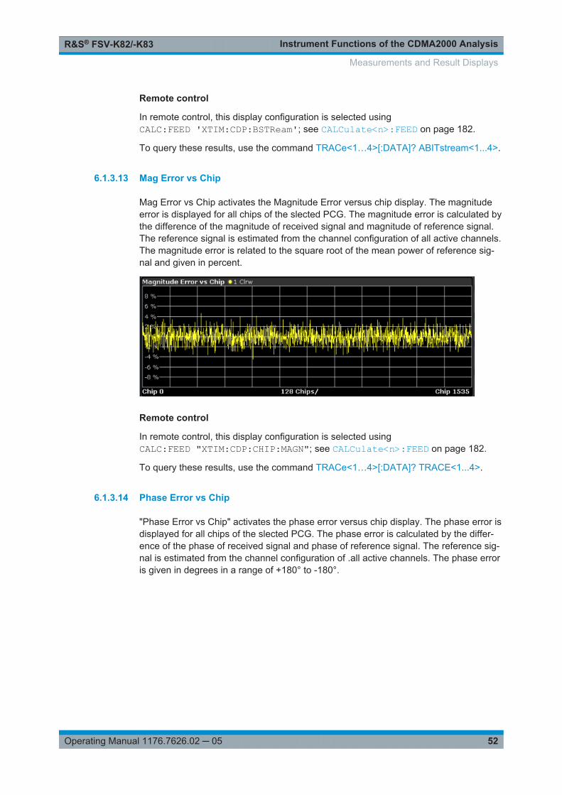
Instrument Functions of the CDMA2000 AnalysisR&S® FSV-K82/-K83
52Operating Manual 1176.7626.02 ─ 05
Remote control
In remote control, this display configuration is selected usingCALC:FEED 'XTIM:CDP:BSTReam'; see CALCulate<n>:FEED on page 182.
To query these results, use the command TRACe<1…4>[:DATA]? ABITstream<1...4>.
6.1.3.13 Mag Error vs Chip
Mag Error vs Chip activates the Magnitude Error versus chip display. The magnitudeerror is displayed for all chips of the slected PCG. The magnitude error is calculated bythe difference of the magnitude of received signal and magnitude of reference signal.The reference signal is estimated from the channel configuration of all active channels.The magnitude error is related to the square root of the mean power of reference sig-nal and given in percent.
Remote control
In remote control, this display configuration is selected usingCALC:FEED "XTIM:CDP:CHIP:MAGN"; see CALCulate<n>:FEED on page 182.
To query these results, use the command TRACe<1…4>[:DATA]? TRACE<1...4>.
6.1.3.14 Phase Error vs Chip
"Phase Error vs Chip" activates the phase error versus chip display. The phase error isdisplayed for all chips of the slected PCG. The phase error is calculated by the differ-ence of the phase of received signal and phase of reference signal. The reference sig-nal is estimated from the channel configuration of .all active channels. The phase erroris given in degrees in a range of +180° to -180°.
Measurements and Result Displays
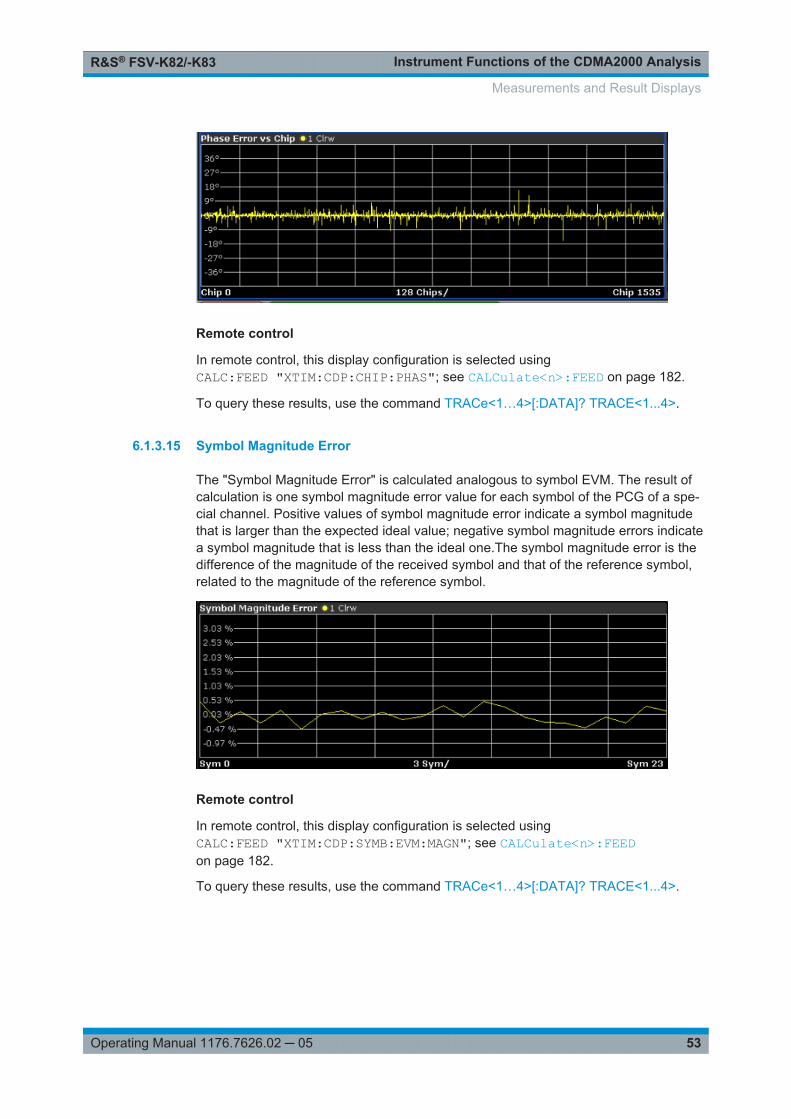
Instrument Functions of the CDMA2000 AnalysisR&S® FSV-K82/-K83
53Operating Manual 1176.7626.02 ─ 05
Remote control
In remote control, this display configuration is selected usingCALC:FEED "XTIM:CDP:CHIP:PHAS"; see CALCulate<n>:FEED on page 182.
To query these results, use the command TRACe<1…4>[:DATA]? TRACE<1...4>.
6.1.3.15 Symbol Magnitude Error
The "Symbol Magnitude Error" is calculated analogous to symbol EVM. The result ofcalculation is one symbol magnitude error value for each symbol of the PCG of a spe-cial channel. Positive values of symbol magnitude error indicate a symbol magnitudethat is larger than the expected ideal value; negative symbol magnitude errors indicatea symbol magnitude that is less than the ideal one.The symbol magnitude error is thedifference of the magnitude of the received symbol and that of the reference symbol,related to the magnitude of the reference symbol.
Remote control
In remote control, this display configuration is selected usingCALC:FEED "XTIM:CDP:SYMB:EVM:MAGN"; see CALCulate<n>:FEEDon page 182.
To query these results, use the command TRACe<1…4>[:DATA]? TRACE<1...4>.
Measurements and Result Displays

Instrument Functions of the CDMA2000 AnalysisR&S® FSV-K82/-K83
54Operating Manual 1176.7626.02 ─ 05
6.1.3.16 Symbol Phase Error
The "Symbol Phase Error" is calculated analogous to symbol EVM. The result of calcu-lation is one symbol phase error value for each symbol of the PCG of a special chan-nel. Positive values of symbol phase error indicate a symbol phase that is larger thanthe expected ideal value; negative symbol phase errors indicate a symbol phase that isless than the ideal one.
Remote control
In remote control, this display configuration is selected usingCALC:FEED "XTIM:CDP:SYMB:EVM:PHAS"; see CALCulate<n>:FEEDon page 182.
To query these results, use the command TRACe<1…4>[:DATA]? TRACE<1...4>.
6.1.4 RF Measurement Results
● Signal Channel Power.............................................................................................54● Adjacent Channel Power.........................................................................................55● Spectrum Emission Mask........................................................................................55● Occupied Bandwidth............................................................................................... 56● Complementary Cumulative Distribution Function (CCDF).....................................56
6.1.4.1 Signal Channel Power
The Signal Channel Power measurement analyses the RF signal power of a singlechannel with 1.2288 MHz bandwidth over a single trace. The displayed results arebased on the root mean square. The configuration is according to the CDMA2000requirements. Beneath the measurement screen the bandwidth and the associatedchannel power are displayed. The other screen elements match that of the screen ofthe Spectrum Analyzer mode. The default settings are in accordance with the 3GPP2specifications.
Setting Default Value
Frequency Span 2 MHz
ACP Standard 1xEV-DO0 MC1
Measurements and Result Displays

Instrument Functions of the CDMA2000 AnalysisR&S® FSV-K82/-K83
55Operating Manual 1176.7626.02 ─ 05
Setting Default Value
Number of adjacent channels 0
Adjacent Channel Power On
For details on the softkeys of the Signal Channel Power measurement refer to thePower softkey in the "Measurement" menu.
6.1.4.2 Adjacent Channel Power
The Adjacent Channel Power measurement analyses the power of the TX channel andthe power of adjacent and alternate channels on the left and right side of the TX chan-nel. The number of TX channels and adjacent channels can be modified as well as theband class. Beneath the measurement screens the bandwidth and power of the TXchannel and the bandwidth, spacing and power of the adjacent and alternate channelsare displayed.
The default settings are in accordance with the 3GPP2 specifications.
Setting Default value
Adjacent Channel Power On
ACP Standard 1xEV-DO0 MC1
Number of adjacent channels 2
For details on the softkeys of the Adjacent Channel Power measurement refer to theCh Power ACLR softkey in the "Measurement" menu.
6.1.4.3 Spectrum Emission Mask
The Spectrum Emission Mask measurement shows the quality of the measured signalby comparing the power values in the frequency range near the carrier against a spec-tral mask that is defined by the 3GPP2 specifications. The limits depend on theselected bandclass. In this way, the performance of the DUT can be tested and theemissions and their distance to the limit be identified.
Note that the 3GPP2 standard does not distinguish between spurious and spectralemissions.
Beneath the measurement screen a table showing the peak list. In the peak list the val-ues for the worst spectral emissions are displayed including their frequency and power.
The default settings of the Spectrum Emission Mask measurement are listed in thetable below.
Measurements and Result Displays

Instrument Functions of the CDMA2000 AnalysisR&S® FSV-K82/-K83
56Operating Manual 1176.7626.02 ─ 05
Setting Default value
Frequency Span 8 MHz
Sweep Time 100 ms
Detector RMS
For details on the softkeys of the Spectrum Emission Mask measurement refer to theSpectrum Emission Mask softkey in the "Measurement" menu.
6.1.4.4 Occupied Bandwidth
The Occupied Bandwidth measurement determines the bandwidth in which the signalpower can be found. By default the bandwidth is displayed in which 99 % of the signalis found. The percentage of the signal power included in the measurement can bemodified. In the top right corner of the screen, the bandwidth and frequency markersare displayed.
The default settings of the Occupied Bandwidth measurement are listed in the tablebelow.
Setting Default value
Occupied Bandwidth ON
Frequency Span 4.2 MHz
Sweep Time 100 ms
RBW 30 kHz
VBW 300 kHz
Detector RMS
For details on the softkeys of the Occupied Bandwidth measurement see OccupiedBandwidth in the "Measurement" menu.
6.1.4.5 Complementary Cumulative Distribution Function (CCDF)
The CCDF measurement displays the CCDF and the Crest factor. The CCDF showsdistribution of the signal amplitudes. For the measurement, a signal section of settablelength is recorded continuously in a zero span. The measurement is useful to deter-mine errors of linear amplifiers. The Crest factor is defined as the ratio of the peakpower and the mean power. Beneath the measurement screen a table containing thenumber of included samples, mean and peak power and the Crest factor is displayed.
The default settings of the CCDF measurement are listed in the table below.
Measurements and Result Displays

Instrument Functions of the CDMA2000 AnalysisR&S® FSV-K82/-K83
57Operating Manual 1176.7626.02 ─ 05
Setting Default value
CCDF ON
RBW 10 MHz
Detector Sample
For details on the softkeys of the CCDF measurement see CCDF in the "Measure-ment" menu.
6.2 Menu and Softkey Description for CDA Measurements
This chapter describes the menus and softkeys available in CDMA2000 BTS Analysismode for CDA measurements. For RF measurements, the softkeys are described inChapter 6.3, "Softkeys and Menus for RF Measurements (K82)", on page 97.
The "Lines" menu is not available in the CDMA2000 BTS Analysis mode.
The "Span" menu is not available for code domain measurements and signal powermeasurements.
The "Bandwidth" menu is not available for code domain measurements measure-ments.
All menus not described here are the same as for the base unit, see the descriptionthere.
Importing and Exporting I/Q DataAs of firmware version 1.60, I/Q data can be imported from a file for processing inR&S FSV-K82/-K83, and captured I/Q data can be stored to a file ("IQ Import"/"IQExport" softkeys in the "Save/Rcl" menu). For details see the base unit description.
To display help to a softkey, press the HELP key and then the softkey for which youwant to display help. To close the help window, press the ESC key. For further infor-mation refer to Chapter 1.3, "How to Use the Help System", on page 8.
6.2.1 Softkeys of the Code Domain Analyzer Menu.............................................................. 58
6.2.2 Softkeys of the Frequency Menu.................................................................................. 80
6.2.3 Softkeys of the Amplitude Menu................................................................................... 81
6.2.4 Softkeys of the Sweep Menu........................................................................................ 84
6.2.5 Softkeys of the Trigger Menu for CDA measurements................................................. 85
6.2.6 Softkeys of the Trace Menu for CDA Measurements....................................................86
6.2.7 Softkeys of the Marker Menu for CDA Measurements..................................................88
Menu and Softkey Description for CDA Measurements

Instrument Functions of the CDMA2000 AnalysisR&S® FSV-K82/-K83
58Operating Manual 1176.7626.02 ─ 05
6.2.8 Softkeys of the Marker To Menu................................................................................... 89
6.2.9 Softkeys of the Auto Set Menu......................................................................................91
6.2.10 Softkeys of the Input/Output Menu for CDA Measurements......................................... 93
6.2.1 Softkeys of the Code Domain Analyzer Menu
The following chapter describes all softkeys available in the "Code Domain Analyzer"menu of the CDMA2000 Analysis options.
Settings Overview......................................................................................................... 59Frontend Settings..........................................................................................................61
└ Center............................................................................................................. 62└ Frequency Offset............................................................................................ 62└ Ref Level.........................................................................................................62└ Ref Level Offset.............................................................................................. 63└ Preamp On/Off................................................................................................63└ Adjust Ref Lvl..................................................................................................63
IQ Capture Settings.......................................................................................................63└ Invert Q........................................................................................................... 63└ Capture Length............................................................................................... 64└ Set Count........................................................................................................64└ Set to Analyze.................................................................................................64└ Trigger Source Free Run................................................................................ 64└ Trigger Source External..................................................................................64└ Trigger Polarity................................................................................................65└ Trigger Offset..................................................................................................65
Channel Table Settings.................................................................................................65└ Channel Search Mode.................................................................................... 66└ Inactive Channel Threshold............................................................................ 66└ Channel Tables...............................................................................................67└ New / Copy / Edit............................................................................................ 67
└ Add Channel.........................................................................................69└ Delete Channel.....................................................................................69└ Meas.....................................................................................................69└ Sort....................................................................................................... 69└ Save......................................................................................................69└ Cancel...................................................................................................69└ Reload.................................................................................................. 70
└ Delete..............................................................................................................70└ Restore Default Tables................................................................................... 70
Demod Settings (BTS mode)........................................................................................ 70└ Base Spreading Factor................................................................................... 70└ PN Offset........................................................................................................ 71└ Multi Carrier.................................................................................................... 71└ Enhanced Algorithm........................................................................................71└ Multi Carrier Filter........................................................................................... 71└ Filter Type.......................................................................................................71└ Roll-Off Factor.................................................................................................72
Menu and Softkey Description for CDA Measurements

Instrument Functions of the CDMA2000 AnalysisR&S® FSV-K82/-K83
59Operating Manual 1176.7626.02 ─ 05
└ Cut Off Frequency...........................................................................................72└ Antenna Diversity............................................................................................72
Base SF/Long Code (MS mode)................................................................................... 73└ Base Spreading Factor................................................................................... 73└ Long Code Mask.............................................................................................74└ Long Code Offset............................................................................................74└ Long Code Gen Mode.....................................................................................74
Result Settings.............................................................................................................. 74└ Power Control Group...................................................................................... 75└ Channel (Code) Number.................................................................................75└ Code Order..................................................................................................... 76└ Code Power.................................................................................................... 76└ Pilot Power (MS mode only)........................................................................... 76└ Power Reference............................................................................................ 76└ Time/Phase Estimation...................................................................................77└ Normalize........................................................................................................77└ Code Domain Overview (MS mode only)........................................................77
Display Config............................................................................................................... 77Select............................................................................................................................ 79
Settings OverviewThis softkey opens the "Settings Overview" dialog box that visualizes the data flow ofthe Code Domain Analyzer and summarizes all of the current settings. In addition, youcan change the current settings via this dialog box.
To reset all values to their default state, press the "Set to Default" button.
Menu and Softkey Description for CDA Measurements

Instrument Functions of the CDMA2000 AnalysisR&S® FSV-K82/-K83
60Operating Manual 1176.7626.02 ─ 05
Figure 6-15: Settings overview in CDMA2000 BTS mode (K82)
Menu and Softkey Description for CDA Measurements

Instrument Functions of the CDMA2000 AnalysisR&S® FSV-K82/-K83
61Operating Manual 1176.7626.02 ─ 05
Figure 6-16: Settings overview in CDMA2000 MS mode (K83)
To change the settings, either use the rotary knob or the cursor keys to change thefocus to any other block or press one of the following buttons:● "Frontend Settings" on page 61● "IQ Capture Settings" on page 63● "Demod Settings (BTS mode)" on page 70● "Base SF/Long Code (MS mode)" on page 73● "Channel Table Settings" on page 65● "Result Settings" on page 74● "Display Config" on page 77When using the rotary knob or the cursor keys, press the ENTER key to open the cor-responding dialog box. The "Settings Overview" dialog box always remains open whilesettings are modified.
Frontend SettingsThis softkey opens the "Frontend Settings" dialog box to modify the following parame-ters:
Menu and Softkey Description for CDA Measurements

Instrument Functions of the CDMA2000 AnalysisR&S® FSV-K82/-K83
62Operating Manual 1176.7626.02 ─ 05
Center ← Frontend SettingsOpens an edit dialog box to enter the center frequency. The allowed range of valuesfor the center frequency depends on the frequency span.
span > 0: spanmin/2 ≤ fcenter ≤ fmax – spanmin/2
span = 0: 0 Hz ≤ fcenter ≤ fmax
fmax and spanmin are specified in the data sheet.
If the bandwidth extension option R&S FSV-B160 is active, center frequencies above7 GHz are not available.
Remote command: [SENSe:]FREQuency:CENTer on page 270
Frequency Offset ← Frontend SettingsOpens an edit dialog box to enter a frequency offset that shifts the displayed frequencyrange by the specified offset.
The softkey indicates the current frequency offset. The allowed values range from-100 GHz to 100 GHz. The default setting is 0 Hz.
Remote command: [SENSe:]FREQuency:OFFSet on page 272
Ref Level ← Frontend SettingsOpens an edit dialog box to enter the reference level in the current unit (dBm, dBµV,etc).
The reference level is the maximum value the AD converter can handle without distor-tion of the measured value. Signal levels above this value will not be measured cor-rectly, which is indicated by the "IFOVL" status display.
Menu and Softkey Description for CDA Measurements

Instrument Functions of the CDMA2000 AnalysisR&S® FSV-K82/-K83
63Operating Manual 1176.7626.02 ─ 05
Remote command: DISPlay[:WINDow<n>]:TRACe<t>:Y[:SCALe]:RLEVel on page 239
Ref Level Offset ← Frontend SettingsOpens an edit dialog box to enter the arithmetic level offset. This offset is added to themeasured level irrespective of the selected unit. The scaling of the y-axis is changedaccordingly. The setting range is ±200 dB in 0.1 dB steps.
Remote command: DISPlay[:WINDow<n>]:TRACe<t>:Y[:SCALe]:RLEVel:OFFSet on page 240
Preamp On/Off ← Frontend SettingsSwitches the preamplifier on and off.
If option R&S FSV-B22 is installed, the preamplifier is only active below 7 GHz.
If option R&S FSV-B24 is installed, the preamplifier is active for all frequencies.
This function is not available for input from the R&S Digital I/Q Interface (optionR&S FSV-B17).
Remote command: INPut:GAIN:STATe on page 306
Adjust Ref Lvl ← Frontend SettingsDefines the optimal reference level for the current measurement automatically.
Remote command: [SENSe:]ADJust:LEVel on page 254
IQ Capture SettingsThis softkey opens the "IQ Capture Settings" dialog box.
Invert Q ← IQ Capture SettingsInverts the sign of the signal's Q-component. The default setting is OFF.
Menu and Softkey Description for CDA Measurements

Instrument Functions of the CDMA2000 AnalysisR&S® FSV-K82/-K83
64Operating Manual 1176.7626.02 ─ 05
Remote command: [SENSe:]CDPower:QINVert on page 249
Capture Length ← IQ Capture SettingsSets the number of PCGs you want to analyze. The input value is always in multiplesof the PCGs. The maximum capture length is 64.
The "Capture Length" field is available if" Set Count" equals 1.
The default value is 3.
Remote command: [SENSe:]CDPower:IQLength on page 245
Set Count ← IQ Capture SettingsDefines the number of consecutive sets to be stored in the instrument's IQ memory.One set consists of 64 PCGs. The R&S FSV/FSVA can capture up to 31360 PCGs(about 26 seconds) in a single sweep, i.e. the possible value range is from 1 to 490sets.
The default setting is 1. In that case you can still define the number of PCGs (see"Capture Length" on page 64). In case you want to capture more than one set, the cap-ture length is always 64. The R&S FSV/FSVA automatically sets the capture length to64 and the "Capture Length" on page 64 field is not available for modification.
Remote command: [SENSe:]CDPower:SET:COUNt on page 250
Set to Analyze ← IQ Capture SettingsSelects a specific set for further analysis. The value range depends on the "Set Count"and is between 0 and "Set Count" – 1.
Remote command: [SENSe:]CDPower:SET on page 250
Trigger Source Free Run ← IQ Capture SettingsThe start of a sweep is not triggered. Once a measurement is completed, another isstarted immediately.
For further details refer to the "Trigger Source" field in the "IQ Capture Settings" dialogbox.
This softkey is available for code domain measurements.
Remote command: TRIG:SOUR IMM, see TRIGger<n>[:SEQuence]:SOURce on page 309
Trigger Source External ← IQ Capture SettingsDefines triggering via a TTL signal at the "EXT TRIG/GATE IN" input connector on therear panel.
An edit dialog box is displayed to define the external trigger level.
For further details refer to the "Trigger Source" field in the "IQ Capture Settings" dialogbox.
This softkey is available for code domain measurements.
Menu and Softkey Description for CDA Measurements

Instrument Functions of the CDMA2000 AnalysisR&S® FSV-K82/-K83
65Operating Manual 1176.7626.02 ─ 05
Remote command: TRIG:SOUR EXT, see TRIGger<n>[:SEQuence]:SOURce on page 309
Trigger Polarity ← IQ Capture SettingsSets the polarity of the trigger source.
The sweep starts after a positive or negative edge of the trigger signal. The default set-ting is "Pos". The setting applies to all modes with the exception of the "Free Run" and"Time" mode.
This softkey is available for code domain measurements.
"Pos" Level triggering: the sweep is stopped by the logic "0" signal andrestarted by the logical "1" signal after the gate delay time haselapsed.
"Neg" Edge triggering: the sweep is continued on a "0" to "1" transition forthe gate length duration after the gate delay time has elapsed.
Remote command: TRIGger<n>[:SEQuence]:SLOPe on page 309[SENSe:]SWEep:EGATe:POLarity on page 285
Trigger Offset ← IQ Capture SettingsOpens an edit dialog box to enter the time offset between the trigger signal and thestart of the sweep.
offset > 0: Start of the sweep is delayed
offset < 0: Sweep starts earlier (pre-trigger)
Only possible for span = 0 (e.g. I/Q Analyzer mode) and gated triggerswitched off
Maximum allowed range limited by the sweep time:
pretriggermax = sweep time
When using the R&S Digital I/Q Interface (R&S FSV-B17) with I/Q Ana-lyzer mode, the maximum range is limited by the number of pretriggersamples.
See the R&S Digital I/Q Interface(R&S FSV-B17) description in the baseunit.
In the "External" or "IF Power" trigger mode, a common input signal is used for bothtrigger and gate. Therefore, changes to the gate delay will affect the trigger delay (trig-ger offset) as well.
Remote command: TRIGger<n>[:SEQuence]:HOLDoff[:TIME] on page 308
Channel Table SettingsOpens the "Channel Table Settings" dialog box and the corresponding submenu.
Menu and Softkey Description for CDA Measurements

Instrument Functions of the CDMA2000 AnalysisR&S® FSV-K82/-K83
66Operating Manual 1176.7626.02 ─ 05
Predefined channel tables allow you to customize measurements very quickly andeasily. They are included in the option by default and contain settings according to spe-cific standards. For details on the predefined channel tables refer to Chapter 6.4.1,"Predefined Channel Tables", on page 151. In addition, new channel tables can becreated and saved to be used in measurements.
Channel Search Mode ← Channel Table SettingsDefines the kind of channel table used for the measurement.
"Auto" The Auto Search mode scans the whole code domain, including allpermissible symbol rates and channel numbers, for active channels.The automatic search provides an overview of the channels con-tained in the signal. If channels are not detected as being active,change the threshold (see "Inactive Channel Threshold"on page 66) or select the Predefined channel search type.
"Predef" Performs the code domain measurement on the basis of the activepredefined channel table. All channels of a channel table areassumed to be active. For further details also refer to the "ChannelTables" on page 67 field and the Chapter 6.4.1, "Predefined Chan-nel Tables", on page 151 .
Remote command: CONFigure:CDPower[:BTS]:CTABle[:STATe] on page 227CONFigure:CDPower[:BTS]:CTABle:SELect on page 231
Inactive Channel Threshold ← Channel Table SettingsDefines the minimum power which a single channel must have compared to the totalsignal in order to be recognized as an active channel. Channels below the specifiedthreshold are regarded as "inactive". The parameter is available in the Auto Searchmode of the Channel Table Settings dialog box.
Menu and Softkey Description for CDA Measurements

Instrument Functions of the CDMA2000 AnalysisR&S® FSV-K82/-K83
67Operating Manual 1176.7626.02 ─ 05
The default value is -60 dB. With this value all channels with signals such as theCDMA2000 test models are located by the Code Domain Power analysis. Decreasethe Inactive Channel Threshold value, if not all channels contained in the signal aredetected.
Remote command: [SENSe:]CDPower:ICThreshold on page 245
Channel Tables ← Channel Table SettingsIn this field a list of the available channel tables is shown. The selected channel table isthe basis for future measurements (until you choose another or activate "AutoSearch").
An active channel table must describe the supplied signal completely, also in regard tothe transmit diversity (see "Antenna Diversity" on page 72).
Using the softkeys, customized channel tables can be defined or existing channeltables can be modified.
The following channel tables are available by default:
"RECENT" Contains the last configuration used before switching from "AutoSearch" to "Predefined"
"BPC_RC4,MPC_RC1,MPC_RC4,TDC_RC4"
Channel tables for BTS mode (K82); configured according to a spe-cific standard
"EACHOP,RCCCHOP,RTCHOP3,RTCHOP5"
Channel tables for MS mode (K83); configured according to a specificstandard
Remote command: CONFigure:CDPower[:BTS]:CTABle:CATalog? on page 227
New / Copy / Edit ← Channel Table SettingsAll three softkeys open a dialog box with the same layout and the same correspondingsubmenu.
The "New" softkey opens the "New Channel Table" dialog box. In this dialog you canbuild a new channel table. All fields are empty.
The "Copy" softkey copies all elements of the selected channel table and opens the"Copy Channel Table" dialog box. The name of the new channel table is set to "Copyof <SourceChannelTableName>".
The "Edit" softkey opens the "Edit Channel Table" dialog box and the correspondingmenu. In this dialog box you can edit an existing channel table.
Note that changes are never saved automatically. Save your channel tables beforeending the application (Save softkey). For more information see Chapter 6.4.2, "Work-ing with Channel Tables", on page 155.
The dialog box contains the following items. You can modify the white fields as youlike. The grey fields can not be modified; these are automatically calculated by theR&S FSV/FSVA:
Menu and Softkey Description for CDA Measurements

Instrument Functions of the CDMA2000 AnalysisR&S® FSV-K82/-K83
68Operating Manual 1176.7626.02 ─ 05
Item Description
Name Enter the name of the selected channel table, which will be saved under<name>.xml. The name is case sensitive and may not contain spaces. Itmust be a valid MS Windows file name. Note that the old channel table fileis not deleted.
Description Enter further information about the channel table.
Channel Type Select one of the channel types from the dropdown menu.
Walsh Ch.SF Enter the Channel Number (Ch) and Spreading Factor (SF). For somechannel types the possible values are limited or preset (e.g. F-PICH, F-TDPICH and F-PDCH).
Symbol Rate/ksps Display of the symbol rate
RC
(BTS mode only)
The Radio Configuration (RC) can be customized for two channel types.For the F-PDCH the you can set the configuration to either 10 (QPSK), 10(8PSK) and 10 (16QAM). For CHAN channels, you can set the radio con-figuration to 1-2 or 3-5.
Mapping (MS mode only) Specifies whether the channel is active on the I or Q branch.
Power/dB Contains the measured relative code domain power. The unit is dB. Thefields are filled with values after pressing the Meas softkey.
State Indicates whether a channel is active or inactive.
DomainConflict A red bullet indicates a conflict of any sorts between two or more channels(e.g. two conflicting channel codes)
Menu and Softkey Description for CDA Measurements

Instrument Functions of the CDMA2000 AnalysisR&S® FSV-K82/-K83
69Operating Manual 1176.7626.02 ─ 05
Add Channel ← New / Copy / Edit ← Channel Table SettingsInserts a new channel below the selected one. For a description of the parameters ofthe channel refer to the "New / Copy / Edit" on page 67 softkey. The default values fora new channel are:
ChannelType CHAN
Walsh.SF 0.64
Sym Rate/ksps automatically calculated
RC
(BTS mode only)
3-5
Mapping (MS mode only) I
Power/dB automatically calculated
State Off
DomainConflict automatically calculated
The R&S FSV/FSVA automatically checks for conflicts between two active channels.
Remote command: CONFigure:CDPower[:BTS]:CTABle:DATA on page 228
Delete Channel ← New / Copy / Edit ← Channel Table SettingsDeletes the selected channel without further notice.
Meas ← New / Copy / Edit ← Channel Table SettingsInitiates a measurement in "Auto Search" mode (see "Channel Search Mode"on page 66). The measurement results are applied to the active channel table. Theactive channel table is overwritten without further notice.
The softkey is only available if the "Auto Search" mode is enabled "in the ChannelTable Settings" dialog box.
Sort ← New / Copy / Edit ← Channel Table SettingsSorts the table according to the following criteria (in the specified order):● Channel state (active channels first, then inactive channels)● Channel type (special channels like F-PICH or F-SYNC first, then data channels)● Spreading factor (in ascending order)● Code number (in ascending order)
Save ← New / Copy / Edit ← Channel Table SettingsSaves the table under its specified name in the xml-format. If you edit a channel tableand want to keep the original channel table, change the name of the edited channeltable before saving it.
Cancel ← New / Copy / Edit ← Channel Table SettingsCloses the dialog box and returns to the "Channel Table Settings" dialog box. Changesapplied to the channel table are lost.
Menu and Softkey Description for CDA Measurements

Instrument Functions of the CDMA2000 AnalysisR&S® FSV-K82/-K83
70Operating Manual 1176.7626.02 ─ 05
Reload ← New / Copy / Edit ← Channel Table SettingsReloads the original content of the copied channel table.
This softkey is available for the "New Channel Table" dialog box and the "Edit ChannelTable" dialog box.
Delete ← Channel Table SettingsDeletes the selected channel table. The currently active channel table cannot bedeleted.
Restore Default Tables ← Channel Table SettingsRestores the predefined channel tables (see Chapter 6.4.1, "Predefined ChannelTables", on page 151 ) to their factory-set values. Existing channel tables with thesame name as default channel tables are replaced by this action. In this way, you canundo unintentional overwriting.
Demod Settings (BTS mode)This softkey opens the "Demodulation Settings" dialog box.
Base Spreading Factor ← Demod Settings (BTS mode)Sets the base spreading factor to either 64 or 128. If you set the base spreading factorto 64 for channels with a base spreading factor of 128 (code class 7), an alias power isdisplayed in the Code Domain Power and Code Domain Error Power diagrams.
Menu and Softkey Description for CDA Measurements

Instrument Functions of the CDMA2000 AnalysisR&S® FSV-K82/-K83
71Operating Manual 1176.7626.02 ─ 05
Remote command: [SENSe:]CDPower:SFACtor on page 250
PN Offset ← Demod Settings (BTS mode)Specifies the Pseudo Noise (PN) offset of the base station. In a CDMA2000 system,the PN offset is used to distinguish the base stations.
The PN offset determines the offset in the circulating PN sequence in multipls of 64chips with reference to the event second clock trigger.
Although the parameter is always available, it has an effect only in External triggermode.
Remote command: [SENSe:]CDPower:PNOFfset on page 248
Multi Carrier ← Demod Settings (BTS mode)Activates or deactivates the Multi Carrier mode. The mode improves the processing ofmulti carrier signals. It allows the measurement on one carrier out of a multi carrier sig-nal.
Remote command: CONFigure:CDPower[:BTS]:MCARrier [:STATe] on page 231
Enhanced Algorithm ← Demod Settings (BTS mode)Activates or deactivates the enhanced algorithm that is used for signal detection onmulti-carrier signals. This algorithm slightly increases the calculation time.
If both the Enhanced Algorithm and the "Multi Carrier Filter" on page 71 are deactiva-ted, the multi carrier mode is automatically switched off.
Remote command: CONFigure:CDPower[:BTS]:MCARrier:MALGo on page 233
Multi Carrier Filter ← Demod Settings (BTS mode)Activates or deactivates the usage of a filter for signal detection on multi-carrier sig-nals.
If both the "Enhanced Algorithm" on page 71 and the Multi Carrier Filter are deactiva-ted, the multi carrier mode is automatically switched off.
Remote command: CONFigure:CDPower[:BTS]:MCARrier:FILTer [:STATe] on page 232
Filter Type ← Demod Settings (BTS mode)Selects the filter type if "Multi Carrier Filter" on page 71 is activated.
Two filter types are available for selection: a low-pass filter and a RRC filter.
By default, the low-pass filter is active. The low-pass filter affects the quality of themeasured signal compared to a measurement without a filter. The frequency responseof the low-pass filter is shown below.
Menu and Softkey Description for CDA Measurements

Instrument Functions of the CDMA2000 AnalysisR&S® FSV-K82/-K83
72Operating Manual 1176.7626.02 ─ 05
The RRC filter comes with an integrated Hamming window. If selected, two more set-tings become available for configuration: the "Roll-Off Factor" on page 72 and the"Cut Off Frequency" on page 72.
Remote command: CONFigure:CDPower[:BTS]:MCARrier:FILTer:TYPE on page 233
Roll-Off Factor ← Demod Settings (BTS mode)Defines the roll-off factor of the RRC filter. The roll-off factor defines the slope of thefilter curve and therefore the excess bandwidth of the filter. Possible values arebetween 0.01 and 0.99 in 0.01 steps. The default value is 0.02.
This parameter is available for the RRC filter.
Remote command: CONFigure:CDPower[:BTS]:MCARrier:FILTer:TYPE on page 233CONFigure:CDPower[:BTS]:MCARrier:FILTer:ROFF on page 232
Cut Off Frequency ← Demod Settings (BTS mode)Defines the cut-off frequency of the RRC filter. The cutoff frequency is the frequency atwhich the passband of the filter begins. Possible values are between 0.1 MHz and 2.4MHz in 1 Hz steps. The default value is 1.25 MHz
This parameter is available for the RRC filter.
Remote command: CONFigure:CDPower[:BTS]:MCARrier:FILTer:TYPE on page 233CONFigure:CDPower[:BTS]:MCARrier:FILTer:COFRequency on page 232
Antenna Diversity ← Demod Settings (BTS mode)Activates or deactivates the orthogonal transmit diversity (two-antenna system) anddefines the antenna for which the results are displayed.
Menu and Softkey Description for CDA Measurements
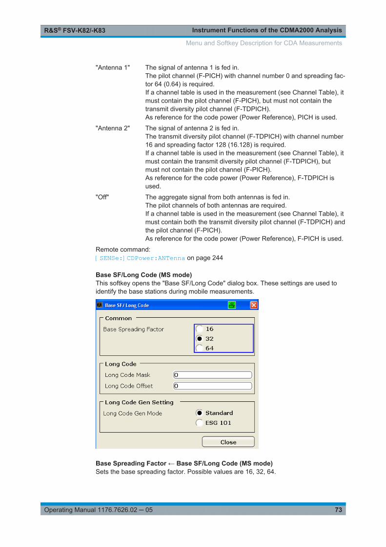
Instrument Functions of the CDMA2000 AnalysisR&S® FSV-K82/-K83
73Operating Manual 1176.7626.02 ─ 05
"Antenna 1" The signal of antenna 1 is fed in.The pilot channel (F-PICH) with channel number 0 and spreading fac-tor 64 (0.64) is required.If a channel table is used in the measurement (see Channel Table), itmust contain the pilot channel (F-PICH), but must not contain thetransmit diversity pilot channel (F-TDPICH).As reference for the code power (Power Reference), PICH is used.
"Antenna 2" The signal of antenna 2 is fed in.The transmit diversity pilot channel (F-TDPICH) with channel number16 and spreading factor 128 (16.128) is required.If a channel table is used in the measurement (see Channel Table), itmust contain the transmit diversity pilot channel (F-TDPICH), butmust not contain the pilot channel (F-PICH).As reference for the code power (Power Reference), F-TDPICH isused.
"Off" The aggregate signal from both antennas is fed in.The pilot channels of both antennas are required.If a channel table is used in the measurement (see Channel Table), itmust contain both the transmit diversity pilot channel (F-TDPICH) andthe pilot channel (F-PICH).As reference for the code power (Power Reference), F-PICH is used.
Remote command: [SENSe:]CDPower:ANTenna on page 244
Base SF/Long Code (MS mode)This softkey opens the "Base SF/Long Code" dialog box. These settings are used toidentify the base stations during mobile measurements.
Base Spreading Factor ← Base SF/Long Code (MS mode)Sets the base spreading factor. Possible values are 16, 32, 64.
Menu and Softkey Description for CDA Measurements

Instrument Functions of the CDMA2000 AnalysisR&S® FSV-K82/-K83
74Operating Manual 1176.7626.02 ─ 05
If channels with a spreading factor of 64 are analyzed, use the base spreading factor64. Otherwise alias power is displayed in the "CODE DOMAIN POWER" and "CODEDOMAIN ERROR POWER" diagram.
Remote command: [SENSe:]CDPower:SFACtor on page 250
Long Code Mask ← Base SF/Long Code (MS mode)Defines the long code mask of the mobile in hexadecimal form. The value range isfrom 0 to 4FFFFFFFFFF.
For the default mask value of 0 the long code offset (refer to the "LONG CODE OFF-SET" softkey) is not taken into consideration.
Remote command: [SENSe:]CDPower:LCODe:MASK on page 246
Long Code Offset ← Base SF/Long Code (MS mode)Defines the long code offset, including the PN offset, in chips in hexadecimal formatwith a 52-bit resolution. This value corresponds to the GPS timing since 6.1.198000:00:00 UTC. This offset is applied at the next trigger pulse (which cannot occur untila setup time of 300 ms has elapsed). The default value is 0.
The setting is ignored if the "Long Code Mask" is set to 0.
The chips offset is calculated as follows:tSinceStartGPS * 1.2288 MChips/swhere tSinceStartGPS is defined in seconds
Remote command: [SENSe:]CDPower:LCODe:OFFSet on page 246
Long Code Gen Mode ← Base SF/Long Code (MS mode)Selects the mode of the long code generation.
"Standard" The cdma2000 standard long code generator is used.
"ESG 101" The Agilent ESG option 101 long code is used; in this case, only sig-nals from that generator can be analysed.
Remote command: [SENSe:]CDPower:LCODe:MODE on page 247
Result SettingsThis softkey opens the "Result Settings" dialog box to modify the following parameters:
Menu and Softkey Description for CDA Measurements

Instrument Functions of the CDMA2000 AnalysisR&S® FSV-K82/-K83
75Operating Manual 1176.7626.02 ─ 05
Power Control Group ← Result SettingsIn some measurements it is possible to highlight the data of a specific PCG. Select thePCG on which to put the focus on in this field. The range of the value depends on the"Capture Length" on page 64 defined in the IQ Capture Settings dialog box. Thereforethe range is (0 to Capture Length-1).
The defined value is valid for any measurement which takes PCGs into account (forfurther information see also the "Select" on page 79 softkey). The selected PCG ishighlighted in red on the screen (as opposed to the others which are displayed in yel-low).
Remote command: [SENSe:]CDPower:SLOT on page 251
Channel (Code) Number ← Result SettingsThe entry in this field corresponds to a specific code to be examined. The valid rangeis from 0 to BSF-1. The base spreading factor (BSF) is either 64 or 128 depending onthe setting of the "Base Spreading Factor" on page 70 field. It can not be edited via thisfield. The selected channel is marked red in the Channel Table. In the Code DomainPower display and the Code Domain Error Power display, all codes belonging to thischannel are marked red.
The defined value is valid for any measurement that takes a selected channel intoaccount. For further information see the "Select" on page 79 softkey.
The rotary knob behavior depends on the result display and the graphic display:● in the Code Domain Power and Code Domain Error result displays, the rotary knob
always selects the adjacent channel. The position of the adjacent channel in thediagram depends on the "Code Order" on page 76.
● in the Channel Table result display, the rotary knob is used to scroll through thelist.
Menu and Softkey Description for CDA Measurements

Instrument Functions of the CDMA2000 AnalysisR&S® FSV-K82/-K83
76Operating Manual 1176.7626.02 ─ 05
Remote command: [SENSe:]CDPower:CODE on page 244
Code Order ← Result SettingsSets the sorting of the channels for the Code Domain Power and Code Domain Errorresult displays.
Hadamard order: By default, the codes are sorted in Hadamard order, i.e. in ascendingorder.
You can see the power of each code in this way; there is no distinctionbetween channels apparent. If there is a channel covering several codes,the display shows the individual power of each code.
Example (for base spreading factor of 64):
0.64, 1.64, 2.64, …, 63.64.
Bit-Reverse order: Bundles the channels with concentrated codes, i.e. all codes of a channelare next to one another. In this way you can see the total power of a con-centrated channel.
Example (for base spreading factor of 64):
0.64, 32.64, 16.64, 48.64, 8.64, 40.64, …, 15.64, 47.64,31.64, 63.64
For further details on the code order refer to the Hadamard and BitReverse CodeTables in the Appendix on page.
Remote command: [SENSe:]CDPower:ORDer on page 247
Code Power ← Result SettingsSelects the y-axis scaling for the Code Domain Power result display.● Absolute scaling shows the code power in dBm.● Relative scaling shows the code power in dB.
You can set the reference in the "Power Reference" on page 76 field.
Remote command: CALCulate<n>:FEED on page 182
Pilot Power (MS mode only) ← Result SettingsDisplays the pilot power in absolute or relative values.
Remote command: [SENSe:]CDPower:PPReference on page 249
Power Reference ← Result SettingsDetermines the reference power for relative power measurements.
Pilot Channel By default, the reference power is the power of the pilot channel. Whichpilot channel is used as the reference depends on the "Antenna Diversity"on page 72.
Total Power The power is measured over one PCG. The reference power is the totalpower of the signal for the corresponding PCG.
Menu and Softkey Description for CDA Measurements

Instrument Functions of the CDMA2000 AnalysisR&S® FSV-K82/-K83
77Operating Manual 1176.7626.02 ─ 05
By default, the power of the channels is referred to the power of the pilot channel (codenumber 0). The power of the pilot channel is identical over all PCGs. Therefore it canbe used as a constant reference for the result display. In contrast, the total power canvary from PCG to PCG due to the possibility of a power level change in the differentcode channels.
In the Power vs PCG result display, with enabled power control and reference to thetotal power of the signal, the power control of the selected channel is not necessarilyreflected.
Example (theoretical):
There is just one data channel in the signal and its power is controlled.
The power is referred to the total power of the signal (which consists only of the contri-bution from this one data channel).
In the Power vs. PCG diagram, a straight line is displayed instead of the expectedpower staircase.
For relative result displays, the reference value Total Power is therefore only meaning-ful if the signal does not contain power control. For signals with enabled power control,use the Pilot Channel setting, since the pilot channel is not subject to power controlunder any circumstances.
Remote command: [SENSe:]CDPower:PREFerence on page 249
Time/Phase Estimation ← Result SettingsActives or deactivates the timing and phase offset calculation of the channels as to thepilot channel. If deactivated or more than 50 active channels are in the signal, the cal-culation does not take place and dashes instead of values are displayed as results.
Remote command: [SENSe:]CDPower:TPMeas on page 251
Normalize ← Result SettingsActivate this parameter to eliminate the DC offset from the signal. By default, theparameter is deactivated.
Remote command: [SENSe:]CDPower:TPMeas on page 251
Code Domain Overview (MS mode only) ← Result SettingsIf enabled, both branches are displayed at once for a code domain power measure-ment (see Chapter 6.1, "Measurements and Result Displays", on page 35). Otherwise,only the selected branch and the result summary are displayed.
Remote command: [SENSe:]CDPower:OVERview on page 248
Display ConfigThis softkey opens the "Display Config" dialog box to select the result display configu-ration.
The Code Domain Analyzer provides the following result display configurations formeasurements in the code domain:
Menu and Softkey Description for CDA Measurements

Instrument Functions of the CDMA2000 AnalysisR&S® FSV-K82/-K83
78Operating Manual 1176.7626.02 ─ 05
Result Display Configuration Definition
Code Domain Power Code Domain Power result display in relative or absolute scal-ing
MS mode: only for the selected branch
Channel Table Channel occupancy table
Power vs PCG Power of the selected channel versus all PCGs
MS mode: only for the selected branch
Result Summary Results in a table
Code Domain Error Power Code Domain Error Power result display
MS mode: only for the selected branch
Composite EVM (RMS) Averaged error between the test signal and the ideal referencesignal
Peak Code Domain Error Projection of the maximum error between the test signal and thereference signal
MS mode: only for the selected branch
Channel Constellation Channel Constellation result display
EVM vs Symbol Error Vector Magnitude result display
Composite Constellation Composite Constellation result display
Power vs Symbol Power of the selected channel and of the selected PCG versusall symbols
Channel Bitstream Display of demodulated bits
For details on the displayed results and default settings refer to Chapter 6.1.3, "CodeDomain Analysis Results", on page 38.
You can configure the result displays via the "Result Settings" on page 74 dialog box.
Menu and Softkey Description for CDA Measurements

Instrument Functions of the CDMA2000 AnalysisR&S® FSV-K82/-K83
79Operating Manual 1176.7626.02 ─ 05
The code domain analyzer can show up to four result diagrams in four differentscreens (windows) at one time. For each screen, you can define which type of resultdiagram is to be displayed, or deactivate the screen temporarily.
The current configuration of the display, i.e. which screens are displayed and whichresult diagram is displayed in which screen, can be stored and retrieved later. Thus,you can easily switch between predefined display configurations.
For details see Chapter 6.1.2, " Configuring the Display", on page 37.
SelectOpens a dialog box to select a specific channel, PCG or branch (MS mode only). Theresults of that channel/PCG/branch are then shown in the result display.
For details on the effects of this softkey, refer to "Channel (Code) Number" on page 75and "Power Control Group" on page 75.
For the following measurements an evaluation on PCG level is possible:● Chapter 6.1.3.1, "Code Domain Power", on page 38● Chapter 6.1.3.2, "Channel Table", on page 40● Chapter 6.1.3.4, "Result Summary", on page 42● Chapter 6.1.3.5, "Code Domain Error Power", on page 44● Chapter 6.1.3.8, "Channel Constellation", on page 47● Chapter 6.1.3.9, "EVM vs Symbol", on page 48● Chapter 6.1.3.10, "Composite Constellation", on page 49● Chapter 6.1.3.11, "Power vs Symbol", on page 50● Chapter 6.1.3.12, "Channel Bitstream", on page 50For the following measurements an evaluation on channel level is possible:● Chapter 6.1.3.3, "Power vs PCG", on page 41● Chapter 6.1.3.4, "Result Summary", on page 42● Chapter 6.1.3.8, "Channel Constellation", on page 47
Menu and Softkey Description for CDA Measurements

Instrument Functions of the CDMA2000 AnalysisR&S® FSV-K82/-K83
80Operating Manual 1176.7626.02 ─ 05
● Chapter 6.1.3.9, "EVM vs Symbol", on page 48● Chapter 6.1.3.11, "Power vs Symbol", on page 50● Chapter 6.1.3.12, "Channel Bitstream", on page 50
Remote command: [SENSe:]CDPower:CODE on page 244[SENSe:]CDPower:SLOT on page 251[SENSe:]CDPower:MAPPing on page 245
6.2.2 Softkeys of the Frequency Menu
The following chapter describes all softkeys available in the "Frequency" menu in"CDMA2000 Analysis" for CDA measurements.
For RF measurements, see the description of the "Frequency" menu for the base unit.
Center........................................................................................................................... 80CF Stepsize...................................................................................................................80Frequency Offset...........................................................................................................80
CenterOpens an edit dialog box to enter the center frequency. The allowed range of valuesfor the center frequency depends on the frequency span.
span > 0: spanmin/2 ≤ fcenter ≤ fmax – spanmin/2
span = 0: 0 Hz ≤ fcenter ≤ fmax
fmax and spanmin are specified in the data sheet.
If the bandwidth extension option R&S FSV-B160 is active, center frequencies above7 GHz are not available.
Remote command: [SENSe:]FREQuency:CENTer on page 270
CF StepsizeOpens an edit dialog box to enter a fixed step size for the center frequency.
The step size defines the value by which the center frequency is increased ordecreased when the arrow keys are pressed. When you use the rotary knob, the cen-ter frequency changes in steps of 10% of the "Center Frequency Stepsize".
This softkey is available for code domain and power vs time measurements.
Remote command: [SENSe:]FREQuency:CENTer:STEP on page 270
Frequency OffsetOpens an edit dialog box to enter a frequency offset that shifts the displayed frequencyrange by the specified offset.
The softkey indicates the current frequency offset. The allowed values range from-100 GHz to 100 GHz. The default setting is 0 Hz.
Menu and Softkey Description for CDA Measurements

Instrument Functions of the CDMA2000 AnalysisR&S® FSV-K82/-K83
81Operating Manual 1176.7626.02 ─ 05
Remote command: [SENSe:]FREQuency:OFFSet on page 272
6.2.3 Softkeys of the Amplitude Menu
The following chapter describes all softkeys available in the "Amplitude" menu in"CDMA2000 BTS Analysis" mode for CDA measurements. For RF measurements, seeChapter 6.3.4, "Softkeys of the Amplitude Menu", on page 130.
Ref Level....................................................................................................................... 81Scale............................................................................................................................. 81
└ Auto Scale Once.............................................................................................81└ Y-Axis Maximum.............................................................................................81└ Y-Axis Minimum..............................................................................................82
Ref Level Offset............................................................................................................ 82Preamp On/Off.............................................................................................................. 82RF Atten Manual/Mech Att Manual............................................................................... 82RF Atten Auto/Mech Att Auto........................................................................................ 83El Atten On/Off.............................................................................................................. 83El Atten Mode (Auto/Man).............................................................................................83Input (AC/DC)................................................................................................................84
Ref LevelOpens an edit dialog box to enter the reference level in the current unit (dBm, dBµV,etc).
The reference level is the maximum value the AD converter can handle without distor-tion of the measured value. Signal levels above this value will not be measured cor-rectly, which is indicated by the "IFOVL" status display.
Remote command: DISPlay[:WINDow<n>]:TRACe<t>:Y[:SCALe]:RLEVel on page 239
ScaleOpens a submenu to define the amplitude scaling type.
This softkey and its submenu is available for code domain measurements in BTSmode (K82).
Auto Scale Once ← ScaleAutomatically scales the y-axis of the grid of the selected screen with respect to themeasured data.
The softkey is available for code domain measurements.
Remote command: DISPlay[:WINDow<n>]:TRACe<t>:Y[:SCALe]:AUTO on page 238
Y-Axis Maximum ← ScaleOpens a dialog box to set the maximum value for the y-axis of the grid of the selectedscreen.
The softkey is available for code domain measurements.
Menu and Softkey Description for CDA Measurements
Instrument Functions of the CDMA2000 AnalysisR&S® FSV-K82/-K83
82Operating Manual 1176.7626.02 ─ 05
Remote command: DISPlay[:WINDow<n>]:TRACe<t>:Y[:SCALe]:MAXimum on page 241
Y-Axis Minimum ← ScaleOpens a dialog box to set the minimum value for the y-axis of the grid of the selectedscreen.
The softkey is available for code domain measurements.
Remote command: DISPlay[:WINDow<n>]:TRACe<t>:Y[:SCALe]:MINimum on page 242
Ref Level OffsetOpens an edit dialog box to enter the arithmetic level offset. This offset is added to themeasured level irrespective of the selected unit. The scaling of the y-axis is changedaccordingly. The setting range is ±200 dB in 0.1 dB steps.
Remote command: DISPlay[:WINDow<n>]:TRACe<t>:Y[:SCALe]:RLEVel:OFFSet on page 240
Preamp On/OffSwitches the preamplifier on and off.
If option R&S FSV-B22 is installed, the preamplifier is only active below 7 GHz.
If option R&S FSV-B24 is installed, the preamplifier is active for all frequencies.
This function is not available for input from the R&S Digital I/Q Interface (optionR&S FSV-B17).
Remote command: INPut:GAIN:STATe on page 306
RF Atten Manual/Mech Att ManualOpens an edit dialog box to enter the attenuation, irrespective of the reference level. Ifelectronic attenuation is activated (option R&S FSV-B25 only; "El Atten Mode Auto"softkey), this setting defines the mechanical attenuation.
The mechanical attenuation can be set in 10 dB steps.
The RF attenuation can be set in 5 dB steps (R&S FSV with option R&S FSV-B25 orR&S FSVA: 1 dB steps). The range is specified in the data sheet. If the current refer-ence level cannot be set for the set RF attenuation, the reference level is adjustedaccordingly.
This function is not available for input from the R&S Digital I/Q Interface (optionR&S FSV-B17).
The RF attenuation defines the level at the input mixer according to the formula:
levelmixer = levelinput – RF attenuation
Note: As of firmware version 1.61, the maximum mixer level allowed is 0 dBm. Mixerlevels above this value may lead to incorrect measurement results, which are indicatedby the "OVLD" status display. The increased mixer level allows for an improved signal,but also increases the risk of overloading the instrument!
Menu and Softkey Description for CDA Measurements

Instrument Functions of the CDMA2000 AnalysisR&S® FSV-K82/-K83
83Operating Manual 1176.7626.02 ─ 05
Remote command: INPut:ATTenuation on page 300
RF Atten Auto/Mech Att AutoSets the RF attenuation automatically as a function of the selected reference level.This ensures that the optimum RF attenuation is always used. It is the default setting.
This function is not available for input from the R&S Digital I/Q Interface (optionR&S FSV-B17).
Remote command: INPut:ATTenuation:AUTO on page 300
El Atten On/OffThis softkey switches the electronic attenuator on or off. This softkey is only availablewith option R&S FSV-B25.
When the electronic attenuator is activated, the mechanical and electronic attenuationcan be defined separately. Note however, that both parts must be defined in the samemode, i.e. either both manually, or both automatically.
This function is not available for input from the R&S Digital I/Q Interface (optionR&S FSV-B17).
● To define the mechanical attenuation, use the RF Atten Manual/Mech Att Manualor RF Atten Auto/Mech Att Auto softkeys.
● To define the electronic attenuation, use the El Atten Mode (Auto/Man) softkey.Note: This function is not available for stop frequencies (or center frequencies in zerospan) >7 GHz. In this case, the electronic and mechanical attenuation are summarizedand the electronic attenuation can no longer be defined individually. As soon as thestop or center frequency is reduced below 7 GHz, this function is available again.When the electronic attenuator is switched off, the corresponding RF attenuation mode(auto/manual) is automatically activated.
Remote command: INPut:EATT:AUTO on page 305
El Atten Mode (Auto/Man)This softkey defines whether the electronic attenuator value is to be set automaticallyor manually. If manual mode is selected, an edit dialog box is opened to enter thevalue. This softkey is only available with option R&S FSV-B25, and only if the elec-tronic attenuator has been activated via the El Atten On/Off softkey.
Note: This function is not available for stop frequencies (or center frequencies in zerospan) >7 GHz. In this case, the electronic and mechanical attenuation are summarizedand the electronic attenuation can no longer be defined individually. As soon as thestop or center frequency is reduced below 7 GHz, electronic attenuation is availableagain. If the electronic attenuation was defined manually, it must be re-defined.The attenuation can be varied in 1 dB steps from 0 to 30 dB. Other entries are roundedto the next lower integer value.
To re-open the edit dialog box for manual value definition, select the "Man" modeagain.
Menu and Softkey Description for CDA Measurements

Instrument Functions of the CDMA2000 AnalysisR&S® FSV-K82/-K83
84Operating Manual 1176.7626.02 ─ 05
If the defined reference level cannot be set for the given RF attenuation, the referencelevel is adjusted accordingly and the warning "Limit reached" is output.
Remote command: INPut:EATT:AUTO on page 305INPut:EATT on page 305
Input (AC/DC)Toggles the RF input of the R&S FSV/FSVA between AC and DC coupling.
This function is not available for input from the R&S Digital I/Q Interface (optionR&S FSV-B17).
Remote command: INPut:COUPling on page 301
6.2.4 Softkeys of the Sweep Menu
The following chapter describes all softkeys available in the "Sweep" menu in"CDMA2000 BTS Analysis" mode for CDA measurements. For RF measurements, seeChapter 6.3.6, "Softkeys of the Sweep Menu", on page 143.
Continuous Sweep........................................................................................................ 84Single Sweep................................................................................................................ 84Continue Single Sweep.................................................................................................84Sweep Count.................................................................................................................85
Continuous SweepSets the continuous sweep mode: the sweep takes place continuously according to thetrigger settings. This is the default setting.
The trace averaging is determined by the sweep count value (see the "Sweep Count"softkey, "Sweep Count" on page 85).
Remote command: INIT:CONT ON, see INITiate<n>:CONTinuous on page 312
Single SweepSets the single sweep mode: after triggering, starts the number of sweeps that aredefined by using the Sweep Count softkey. The measurement stops after the definednumber of sweeps has been performed.
Remote command: INIT:CONT OFF, see INITiate<n>:CONTinuous on page 312
Continue Single SweepRepeats the number of sweeps set by using the Sweep Count softkey, without deletingthe trace of the last measurement.
This is particularly of interest when using the trace configurations "Average" or "MaxHold" to take previously recorded measurements into account for averaging/maximumsearch.
Menu and Softkey Description for CDA Measurements

Instrument Functions of the CDMA2000 AnalysisR&S® FSV-K82/-K83
85Operating Manual 1176.7626.02 ─ 05
Remote command: INITiate<n>:CONMeas on page 311
Sweep CountOpens an edit dialog box to enter the number of sweeps to be performed in the singlesweep mode. Values from 0 to 32767 are allowed. If the values 0 or 1 are set, onesweep is performed. The sweep count is applied to all the traces in a diagram.
If the trace configurations "Average", "Max Hold" or "Min Hold" are set, the sweepcount value also determines the number of averaging or maximum search procedures.
In continuous sweep mode, if sweep count = 0 (default), averaging is performed over10 sweeps. For sweep count =1, no averaging, maxhold or minhold operations are per-formed.
Remote command: [SENSe:]SWEep:COUNt on page 284
6.2.5 Softkeys of the Trigger Menu for CDA measurements
The following chapter describes all softkeys available in the "Trigger" menu for CDAmeasurements.
For RF measurements, see the description for the base unit.
Trigger Source Free Run.............................................................................................. 85Trigger Source External................................................................................................ 85Trigger Polarity..............................................................................................................86Trigger Offset................................................................................................................ 86
Trigger Source Free RunThe start of a sweep is not triggered. Once a measurement is completed, another isstarted immediately.
For further details refer to the "Trigger Source" field in the "IQ Capture Settings" dialogbox.
This softkey is available for code domain measurements.
Remote command: TRIG:SOUR IMM, see TRIGger<n>[:SEQuence]:SOURce on page 309
Trigger Source ExternalDefines triggering via a TTL signal at the "EXT TRIG/GATE IN" input connector on therear panel.
An edit dialog box is displayed to define the external trigger level.
For further details refer to the "Trigger Source" field in the "IQ Capture Settings" dialogbox.
This softkey is available for code domain measurements.
Menu and Softkey Description for CDA Measurements

Instrument Functions of the CDMA2000 AnalysisR&S® FSV-K82/-K83
86Operating Manual 1176.7626.02 ─ 05
Remote command: TRIG:SOUR EXT, see TRIGger<n>[:SEQuence]:SOURce on page 309
Trigger PolaritySets the polarity of the trigger source.
The sweep starts after a positive or negative edge of the trigger signal. The default set-ting is "Pos". The setting applies to all modes with the exception of the "Free Run" and"Time" mode.
This softkey is available for code domain measurements.
"Pos" Level triggering: the sweep is stopped by the logic "0" signal andrestarted by the logical "1" signal after the gate delay time haselapsed.
"Neg" Edge triggering: the sweep is continued on a "0" to "1" transition forthe gate length duration after the gate delay time has elapsed.
Remote command: TRIGger<n>[:SEQuence]:SLOPe on page 309[SENSe:]SWEep:EGATe:POLarity on page 285
Trigger OffsetOpens an edit dialog box to enter the time offset between the trigger signal and thestart of the sweep.
offset > 0: Start of the sweep is delayed
offset < 0: Sweep starts earlier (pre-trigger)
Only possible for span = 0 (e.g. I/Q Analyzer mode) and gated triggerswitched off
Maximum allowed range limited by the sweep time:
pretriggermax = sweep time
When using the R&S Digital I/Q Interface (R&S FSV-B17) with I/Q Ana-lyzer mode, the maximum range is limited by the number of pretriggersamples.
See the R&S Digital I/Q Interface(R&S FSV-B17) description in the baseunit.
In the "External" or "IF Power" trigger mode, a common input signal is used for bothtrigger and gate. Therefore, changes to the gate delay will affect the trigger delay (trig-ger offset) as well.
Remote command: TRIGger<n>[:SEQuence]:HOLDoff[:TIME] on page 308
6.2.6 Softkeys of the Trace Menu for CDA Measurements
The following chapter describes all softkeys available in the "Trace" menu in"CDMA2000 BTS Analysis" Mode for Code Domain Analysis measurements.
For RF measurements, see the description for the base unit.
Menu and Softkey Description for CDA Measurements
Instrument Functions of the CDMA2000 AnalysisR&S® FSV-K82/-K83
87Operating Manual 1176.7626.02 ─ 05
Clear Write.................................................................................................................... 87Max Hold....................................................................................................................... 87Min Hold........................................................................................................................ 87Average.........................................................................................................................87View.............................................................................................................................. 88
Clear WriteOverwrite mode: the trace is overwritten by each sweep. This is the default setting.
All available detectors can be selected.
Remote command: DISP:TRAC:MODE WRIT, see DISPlay[:WINDow<n>]:TRACe<t>:MODEon page 236
Max HoldThe maximum value is determined over several sweeps and displayed. The R&S FSV/FSVA saves the sweep result in the trace memory only if the new value is greater thanthe previous one.
The detector is automatically set to "Positive Peak".
This mode is especially useful with modulated or pulsed signals. The signal spectrumis filled up upon each sweep until all signal components are detected in a kind of enve-lope.
This mode is not available for statistics measurements.
Remote command: DISP:TRAC:MODE MAXH, see DISPlay[:WINDow<n>]:TRACe<t>:MODEon page 236
Min HoldThe minimum value is determined from several measurements and displayed. TheR&S FSV/FSVA saves the smallest of the previously stored/currently measured valuesin the trace memory.
The detector is automatically set to "Negative Peak".
This mode is useful e.g. for making an unmodulated carrier in a composite signal visi-ble. Noise, interference signals or modulated signals are suppressed whereas a CWsignal is recognized by its constant level.
This mode is not available for statistics measurements.
Remote command: DISP:TRAC:MODE MINH, see DISPlay[:WINDow<n>]:TRACe<t>:MODEon page 236
AverageThe average is formed over several sweeps. The Sweep Count determines the numberof averaging procedures.
All available detectors can be selected. If the detector is automatically selected, thesample detector is used (see Chapter 6.4.3, "Detector Overview", on page 156).
This mode is not available for statistics measurements.
Menu and Softkey Description for CDA Measurements

Instrument Functions of the CDMA2000 AnalysisR&S® FSV-K82/-K83
88Operating Manual 1176.7626.02 ─ 05
Remote command: DISP:TRAC:MODE AVER, see DISPlay[:WINDow<n>]:TRACe<t>:MODEon page 236
ViewThe current contents of the trace memory are frozen and displayed.
Note: If a trace is frozen, the instrument settings, apart from level range and referencelevel (see below), can be changed without impact on the displayed trace. The fact thatthe displayed trace no longer matches the current instrument setting is indicated by the
icon on the tab label.If the level range or reference level is changed, the R&S FSV/FSVA automaticallyadapts the measured data to the changed display range. This allows an amplitudezoom to be made after the measurement in order to show details of the trace.
Remote command: DISP:TRAC:MODE VIEW, see DISPlay[:WINDow<n>]:TRACe<t>:MODEon page 236
6.2.7 Softkeys of the Marker Menu for CDA Measurements
The following chapter describes all softkeys available in the "Marker" menu for CDAmeasurements. For RF measurements, see Chapter 6.3.7, "Softkeys of the MarkerMenu for RF Measurements", on page 147.
Marker 1/2/3/4............................................................................................................... 88Marker Norm/Delta........................................................................................................89All Marker Off................................................................................................................ 89
Marker 1/2/3/4Selects the corresponding marker and activates it.
Marker 1 is always a normal marker. After Marker 2 to 4 have been switched on, theyare delta markers that are referenced to Marker 1. These markers can be convertedinto markers with absolute value displays using the "Marker Norm/Delta" softkey.When Marker 1 is the active marker, pressing the "Marker Norm/Delta" softkeyswitches on an additional delta marker. Pressing the "Marker 1" to "Marker 4" softkeyagain switches the corresponding marker off.
For the Channel Bitstream measurement only one marker (Marker 1) is available. Itcan be used for scrolling and to display the number and value of a bit.
Remote command: CALCulate<n>:MARKer<m>[:STATe] on page 214CALCulate<n>:MARKer<m>:X on page 215CALCulate<n>:MARKer<m>:Y? on page 217CALCulate<n>:DELTamarker<m>[:STATe] on page 197CALCulate<n>:DELTamarker<m>:X on page 198CALCulate<n>:DELTamarker<m>:X:RELative? on page 198CALCulate<n>:DELTamarker<m>:Y? on page 198
Menu and Softkey Description for CDA Measurements

Instrument Functions of the CDMA2000 AnalysisR&S® FSV-K82/-K83
89Operating Manual 1176.7626.02 ─ 05
Marker Norm/DeltaChanges the active marker to a normal (norm) or delta marker (with respect to marker1).
Remote command: CALCulate<n>:MARKer<m>[:STATe] on page 214CALCulate<n>:DELTamarker<m>[:STATe] on page 197
All Marker OffSwitches all markers off. It also switches off all functions and displays that are associ-ated with the markers/delta markers.
Remote command: CALCulate<n>:MARKer<m>:AOFF on page 211
6.2.8 Softkeys of the Marker To Menu
The following chapter describes all softkeys available in the "Marker To" menu in"CDMA2000 BTS Analysis" mode for CDA measurements.
For RF measurements, see the description for the base unit.
Select 1/2/3/4/∆............................................................................................................. 89Peak.............................................................................................................................. 89Next Peak......................................................................................................................89Next Peak Mode............................................................................................................90F-PICH (BTS mode only).............................................................................................. 90F-TDPICH (BTS mode only)......................................................................................... 90PICH (MS mode only)................................................................................................... 90Min................................................................................................................................ 90Next Min........................................................................................................................ 91Next Min Mode.............................................................................................................. 91Center =Mkr Freq (span > 0).........................................................................................91
Select 1/2/3/4/∆Selects the normal marker or the delta marker and activates the marker. "∆" stands fordelta marker 1.
CALCulate<n>:MARKer<m>[:STATe] on page 214
CALCulate<n>:MARKer<m>:X on page 215
CALCulate<n>:MARKer<m>:Y? on page 217
PeakSets the active marker/delta marker to the highest maximum of the trace.
Remote command: CALCulate<n>:MARKer<m>:MAXimum[:PEAK] on page 212
Next PeakSets the active marker/delta marker to the next maximum of the selected trace.
Menu and Softkey Description for CDA Measurements

Instrument Functions of the CDMA2000 AnalysisR&S® FSV-K82/-K83
90Operating Manual 1176.7626.02 ─ 05
Remote command: CALCulate<n>:MARKer<m>:MAXimum:NEXT on page 212CALCulate<n>:DELTamarker<m>:MAXimum:NEXT on page 194
Next Peak ModeSelects the mode of the Next Peak softkey.
This softkey is available for code domain measurements.
Three settings are available:
"<" Sets the active marker/delta marker to the next maximum left to themarker of the selected trace.
"abs" Sets the active marker/delta marker to the next lower maximum of theselected trace.
">" Sets the active marker/delta marker to the next maximum right to themarker of the selected trace.
Remote command: CALC:MARK:MAX:LEFT (<): CALCulate<n>:MARKer<m>:MAXimum:LEFTon page 211CALCulate<n>:DELTamarker<m>:MAXimum:LEFT on page 194CALC:MARK:MAX:RIGH (>): CALCulate<n>:MARKer<m>:MAXimum:RIGHton page 212CALCulate<n>:DELTamarker<m>:MAXimum:RIGHt on page 195CALC:DELT:MAX:NEXT (abs): CALCulate<n>:MARKer<m>:MAXimum:NEXTon page 212CALCulate<n>:DELTamarker<m>:MAXimum:NEXT on page 194
F-PICH (BTS mode only)Sets the marker to the F-PICH channel. The softkey is only available if the x-axis of theactive screen is a code axis.
This softkey is available for code domain measurements.
CALCulate<n>:MARKer<m>:FUNCtion:PICH on page 186
F-TDPICH (BTS mode only)Sets the marker to the F-TDPICH channel. The softkey is only available if the x-axis ofthe active screen is a code axis.
This softkey is available for code domain measurements.
CALCulate<n>:MARKer<m>:FUNCtion:TDPIch on page 190
PICH (MS mode only)Sets the marker to the PICH channel. The softkey is only available if the x-axis of theactive screen is a code axis.
This softkey is available for code domain measurements.
CALCulate<n>:MARKer<m>:FUNCtion:PICH on page 186
MinSets the active marker/delta marker to the minimum of the selected trace.
Menu and Softkey Description for CDA Measurements

Instrument Functions of the CDMA2000 AnalysisR&S® FSV-K82/-K83
91Operating Manual 1176.7626.02 ─ 05
Remote command: CALCulate<n>:MARKer<m>:MINimum[:PEAK] on page 214
Next MinSets the active marker/delta marker to the next minimum of the selected trace.
Remote command: CALCulate<n>:MARKer<m>:MINimum:NEXT on page 213CALCulate<n>:DELTamarker<m>:MINimum:NEXT on page 196
Next Min ModeSets the mode for the Next Min softkey.
This softkey is available for code domain measurements.
Three settings are available:
"<" Sets the active marker/delta marker to the next minimum left to themarker of the selected trace.
"abs" Sets the active marker/delta marker to the next higher minimum ofthe selected trace.
">" Sets the active marker/delta marker to the next minimum right to themarker of the selected trace.
Remote command: CALC:MARK:MIN:LEFT (>): CALCulate<n>:MARKer<m>:MINimum:LEFTon page 213CALCulate<n>:DELTamarker<m>:MINimum:LEFT on page 195CALC:MARK:MIN:RIGH (>): CALCulate<n>:MARKer<m>:MINimum:RIGHton page 214CALCulate<n>:DELTamarker<m>:MINimum:RIGHt on page 196CALC:MARK:MIN:NEXT (abs): CALCulate<n>:MARKer<m>:MINimum:NEXTon page 213CALCulate<n>:DELTamarker<m>:MINimum:NEXT on page 196
Center =Mkr Freq (span > 0)Sets the center frequency to the current marker or delta marker frequency. A signalcan thus be set to as center frequency, for example to examine it in detail with asmaller span.
This softkey is available for RF measurements.
Remote command: CALCulate<n>:MARKer<m>:FUNCtion:CENTer on page 186
6.2.9 Softkeys of the Auto Set Menu
The following chapter describes all softkeys available in the "Auto Set" menu in"CDMA2000 BTS Analysis" mode for CDA measurements.
Auto All..........................................................................................................................92Auto Freq...................................................................................................................... 92Auto Level..................................................................................................................... 92
Menu and Softkey Description for CDA Measurements

Instrument Functions of the CDMA2000 AnalysisR&S® FSV-K82/-K83
92Operating Manual 1176.7626.02 ─ 05
Settings......................................................................................................................... 92└ Meas Time Manual......................................................................................... 92└ Meas Time Auto..............................................................................................92└ Upper Level Hysteresis...................................................................................93└ Lower Level Hysteresis...................................................................................93
Auto AllPerforms all automatic settings.● "Auto Freq" on page 92● "Auto Level" on page 92
Remote command: [SENSe:]ADJust:ALL on page 252
Auto FreqDefines the center frequency and the reference level automatically by determining thehighest frequency level in the frequency span. This function uses the signal counter;thus it is intended for use with sinusoidal signals.
This function is not available for input from the R&S Digital I/Q Interface (optionR&S FSV-B17).
Remote command: [SENSe:]ADJust:FREQuency on page 254
Auto LevelDefines the optimal reference level for the current measurement automatically.
The measurement time for automatic leveling can be defined using the Settings soft-key.
Remote command: [SENSe:]ADJust:LEVel on page 254
SettingsOpens a submenu to define settings for automatic leveling.
Possible settings are:● "Meas Time Manual" on page 92● "Meas Time Auto" on page 92
Meas Time Manual ← SettingsOpens an edit dialog box to enter the duration of the level measurement in seconds.The level measurement is used to determine the optimal reference level automatically(see the "Auto Level" softkey, "Auto Level" on page 92). The default value is 1 ms.
Remote command: [SENSe:]ADJust:CONFigure:LEVel:DURation on page 253
Meas Time Auto ← SettingsThe level measurement is used to determine the optimal reference level automatically(see the Auto Level softkey).
This softkey resets the level measurement duration for automatic leveling to the defaultvalue of 100 ms.
Menu and Softkey Description for CDA Measurements

Instrument Functions of the CDMA2000 AnalysisR&S® FSV-K82/-K83
93Operating Manual 1176.7626.02 ─ 05
Upper Level Hysteresis ← SettingsDefines an upper threshold the signal must exceed before the reference level is auto-matically adjusted when the "Auto Level" function is performed.
Remote command: [SENSe:]ADJust:CONFiguration:HYSTeresis:UPPer on page 253
Lower Level Hysteresis ← SettingsDefines a lower threshold the signal must exceed before the reference level is auto-matically adjusted when the "Auto Level" function is performed.
Remote command: [SENSe:]ADJust:CONFiguration:HYSTeresis:LOWer on page 252
6.2.10 Softkeys of the Input/Output Menu for CDA Measurements
The following chapter describes all softkeys available in the "Input/Output" menu forCDA measurements. For RF measurements, see Chapter 6.3.8, "Softkeys of the Input/Output Menu for RF Measurements", on page 149.
Input (AC/DC)................................................................................................................93Noise Source.................................................................................................................93Signal Source................................................................................................................94
└ Input Path........................................................................................................94└ Connected Device...........................................................................................94└ Input Sample Rate.......................................................................................... 94└ Full Scale Level...............................................................................................94└ Level Unit........................................................................................................94└ Adjust Reference Level to Full Scale Level.................................................... 94
Digital IQ Info................................................................................................................ 95EXIQ..............................................................................................................................95
└ TX Settings..................................................................................................... 96└ RX Settings.....................................................................................................96└ Send To.......................................................................................................... 96└ Firmware Update............................................................................................ 96└ R&S Support...................................................................................................96└ DigIConf..........................................................................................................96
Input (AC/DC)Toggles the RF input of the R&S FSV/FSVA between AC and DC coupling.
This function is not available for input from the R&S Digital I/Q Interface (optionR&S FSV-B17).
Remote command: INPut:COUPling on page 301
Noise SourceSwitches the supply voltage for an external noise source on or off. For details on con-nectors refer to the R&S FSV/FSVA Quick Start Guide, "Front and Rear Panel" chap-ter.
Menu and Softkey Description for CDA Measurements
Instrument Functions of the CDMA2000 AnalysisR&S® FSV-K82/-K83
94Operating Manual 1176.7626.02 ─ 05
Remote command: DIAGnostic<n>:SERVice:NSOurce on page 310
Signal SourceOpens a dialog box to select the signal source.
For "Digital Baseband (I/Q)", the source can also be configured here.
Input Path ← Signal SourceDefines whether the "RF Radio Frequency" or the "Digital IQ" input path is used formeasurements. "Digital IQ" is only available if option R&S FSV-B17 (R&S Digital I/QInterface) is installed.
Note: Note that the input path defines the characteristics of the signal, which differ sig-nificantly between the RF input and digital input.
Remote command: INPut:SELect on page 307
Connected Device ← Signal SourceDisplays the name of the device connected to the optional R&S Digital I/Q Interface(R&S FSV-B17) to provide Digital IQ input. The device name cannot be changed here.
The device name is unknown.
Remote command: INPut:DIQ:CDEVice on page 301
Input Sample Rate ← Signal SourceDefines the sample rate of the digital I/Q signal source. This sample rate must corre-spond with the sample rate provided by the connected device, e.g. a generator.
Remote command: INPut:DIQ:SRATe on page 304
Full Scale Level ← Signal SourceThe "Full Scale Level" defines the level that should correspond to an I/Q sample withthe magnitude "1".
The level can be defined either in dBm or Volt.
Remote command: INPut:DIQ:RANGe[:UPPer] on page 303
Level Unit ← Signal SourceDefines the unit used for the full scale level.
Remote command: INPut:DIQ:RANGe[:UPPer]:UNIT on page 303
Adjust Reference Level to Full Scale Level ← Signal SourceIf enabled, the reference level is adjusted to the full scale level automatically if anychange occurs.
Menu and Softkey Description for CDA Measurements

Instrument Functions of the CDMA2000 AnalysisR&S® FSV-K82/-K83
95Operating Manual 1176.7626.02 ─ 05
Remote command: INPut:DIQ:RANGe:COUPling on page 303
Digital IQ InfoDisplays a dialog box with information on the digital I/Q input and output connection viathe optional R&S Digital I/Q Interface (R&S FSV-B17), if available. The informationincludes:● Device identification● Used port● (Maximum) digital input/output sample rates and maximum digital input/output
transfer rates● Status of the connection protocol● Status of the PRBS descewing test
For details see "Interface Status Information" in "Instrument Functions - R&S Digital I/QInterface (Option R&S FSV-B17)" in the description of the base unit.
Remote command: INPut:DIQ:CDEVice on page 301
EXIQOpens a configuration dialog box for an optionally connected R&S EX-IQ-BOX and asubmenu to access the main settings quickly.
Note: The EX-IQ-Box functionality is not supported for R&S FSV models1307.9002Kxx.If the optional R&S DigIConf software is installed, the submenu consists only of onekey to access the software. Note that R&S DigIConf requires a USB connection(not LAN!) from the R&S FSV/FSVA to the R&S EX-IQ-BOX in addition to the R&SDigital I/Q Interface connection. R&S DigIConf version 2.10 or higher is required.
Menu and Softkey Description for CDA Measurements

Instrument Functions of the CDMA2000 AnalysisR&S® FSV-K82/-K83
96Operating Manual 1176.7626.02 ─ 05
For typical applications of the R&S EX-IQ-BOX see also the description of the R&SDigital I/Q Interface (R&S FSV-B17) in the base unit manual.
For details on configuration see the "R&S®Ex I/Q Box - External Signal Interface Mod-ule Manual".
For details on installation and operation of the R&S DigIConf software, see the"R&S®EX-IQ-BOX Digital Interface Module R&S®DigIConf Software Operating Man-ual".
TX Settings ← EXIQOpens the "EX-IQ-BOX Settings" dialog box to configure the R&S FSV/FSVA for digitaloutput to a connected device ("Transmitter" Type).
RX Settings ← EXIQOpens the "EX-IQ-BOX Settings" dialog box to configure the R&S FSV/FSVA for digitalinput from a connected device ("Receiver" Type).
Send To ← EXIQThe configuration settings defined in the dialog box are transferred to the R&S EX-IQ-BOX.
Firmware Update ← EXIQIf a firmware update for the R&S EX-IQ-BOX is delivered with the R&S FSV/FSVA firm-ware, this function is available. In this case, when you select the softkey, the firmwareupdate is performed.
R&S Support ← EXIQStores useful information for troubleshooting in case of errors.
This data is stored in the C:\R_S\Instr\user\Support directory on the instru-ment.
If you contact the Rohde&Schwarz support to get help for a certain problem, sendthese files to the support in order to identify and solve the problem faster.
DigIConf ← EXIQStarts the optional R&S DigIConf application. This softkey is only available if theoptional software is installed.
To return to the R&S FSV/FSVA application, press any key on the front panel. Theapplication is displayed with the "EXIQ" menu, regardless of which key was pressed.
For details on the R&S DigIConf application, see the "R&S®EX-IQ-BOX Digital Inter-face Module R&S®DigIConf Software Operating Manual".
Note: If you close the R&S DigIConf window using the "Close" icon, the window isminimized, not closed.If you select the "File > Exit" menu item in the R&S DigIConf window, the application isclosed. Note that in this case the settings are lost and the EX-IQ-BOX functionality isno longer available until you restart the application using the "DigIConf" softkey in theR&S FSV/FSVA once again.
Menu and Softkey Description for CDA Measurements

Instrument Functions of the CDMA2000 AnalysisR&S® FSV-K82/-K83
97Operating Manual 1176.7626.02 ─ 05
Remote command: Remote commands for the R&S DigIConf software always begin with SOURce:EBOX.Such commands are passed on from the R&S FSV/FSVA to the R&S DigIConf auto-matically which then configures the R&S EX-IQ-BOX via the USB connection.All remote commands available for configuration via the R&S DigIConf software aredescribed in the "R&S®EX-IQ-BOX Digital Interface Module R&S®DigIConf SoftwareOperating Manual".Example 1:SOURce:EBOX:*RSTSOURce:EBOX:*IDN?Result:"Rohde&Schwarz,DigIConf,02.05.436 Build 47"Example 2:SOURce:EBOX:USER:CLOCk:REFerence:FREQuency 5MHZDefines the frequency value of the reference clock.
6.3 Softkeys and Menus for RF Measurements (K82)
The following chapter describes the softkeys and menus available for RF measure-ments in CDMA2000 BTS Analysis mode.
All menus not described here are the same as for the base unit, see the descriptionthere.
6.3.1 Softkeys of the Measurement Menu............................................................................. 97
6.3.2 Softkeys of the Frequency Menu................................................................................ 126
6.3.3 Softkeys of the Span Menu for RF Measurements..................................................... 129
6.3.4 Softkeys of the Amplitude Menu................................................................................. 130
6.3.5 Softkeys of the Bandwidth Menu.................................................................................137
6.3.6 Softkeys of the Sweep Menu...................................................................................... 143
6.3.7 Softkeys of the Marker Menu for RF Measurements.................................................. 147
6.3.8 Softkeys of the Input/Output Menu for RF Measurements..........................................149
6.3.1 Softkeys of the Measurement Menu
The following chapter describes all softkeys available in the "Measurement" menu in"CDMA2000 Analysis" or "1xEV-DO Analysis" mode. It is possible that your instrumentconfiguration does not provide all softkeys. If a softkey is only available with a specialoption, model or (measurement) mode, this information is delivered in the correspond-ing softkey description.
Code Domain Analyzer............................................................................................... 100Power.......................................................................................................................... 100
└ Adjust Ref Lvl................................................................................................100Ch Power ACLR..........................................................................................................100
Softkeys and Menus for RF Measurements (K82)

Instrument Functions of the CDMA2000 AnalysisR&S® FSV-K82/-K83
98Operating Manual 1176.7626.02 ─ 05
└ Bandclass..................................................................................................... 100└ CP/ACLR Settings........................................................................................ 101
└ # of TX Chan.......................................................................................101└ # of Adj Chan......................................................................................102└ Channel Setup....................................................................................102
└ Bandwidth.................................................................................103└ ACLR Reference............................................................ 104
└ Spacing.....................................................................................104└ Names...................................................................................... 105└ Weighting Filter.........................................................................105└ Limits........................................................................................ 106
└ Limit Checking................................................................106└ Relative Limit..................................................................107└ Absolute Limit.................................................................107└ Check............................................................................. 107
└ Chan Pwr/Hz.......................................................................................107└ Power Mode........................................................................................107
└ Clear/Write................................................................................107└ Max Hold.................................................................................. 108
└ Select Trace........................................................................................108└ ACLR (Abs/Rel).................................................................................. 108└ Adjust Settings....................................................................................108
└ Sweep Time..................................................................................................108└ Fast ACLR (On/Off)...................................................................................... 109└ Set CP Reference.........................................................................................109└ Noise Correction........................................................................................... 109└ Adjust Ref Lvl................................................................................................110
Spectrum Emission Mask............................................................................................110└ Sweep List.................................................................................................... 110
└ Sweep List dialog box.........................................................................110└ Range Start / Range Stop........................................................ 111└ Fast SEM..................................................................................111└ Filter Type.................................................................................111└ RBW......................................................................................... 111└ VBW......................................................................................... 112└ Sweep Time Mode....................................................................112└ Sweep Time..............................................................................112└ Ref. Level................................................................................. 112└ RF Att. Mode............................................................................ 112└ RF Attenuator........................................................................... 112└ Preamp.....................................................................................112└ Transd. Factor.......................................................................... 112└ Limit Check 1-4.........................................................................113└ Abs Limit Start.......................................................................... 113└ Abs Limit Stop.......................................................................... 113└ Rel Limit Start...........................................................................113└ Rel Limit Stop........................................................................... 114
└ Close Sweep List................................................................................114└ Insert before Range............................................................................114└ Insert after Range...............................................................................114
Softkeys and Menus for RF Measurements (K82)

Instrument Functions of the CDMA2000 AnalysisR&S® FSV-K82/-K83
99Operating Manual 1176.7626.02 ─ 05
└ Delete Range......................................................................................114└ Symmetric Setup................................................................................ 115└ Edit Reference Range........................................................................ 115
└ List Evaluation...............................................................................................116└ List Evaluation (On/Off)...................................................................... 116└ Margin.................................................................................................116└ Show Peaks........................................................................................116└ Save Evaluation List........................................................................... 116
└ ASCII File Export......................................................................117└ Decim Sep................................................................................117
└ Edit Reference Range...................................................................................117└ Edit Power Classes.......................................................................................118
└ Used Power Classes.......................................................................... 119└ PMin/PMax......................................................................................... 119└ Sweep List.......................................................................................... 119└ Add/Remove.......................................................................................119
└ Bandclass..................................................................................................... 119└ Load Standard.............................................................................................. 120└ Save As Standard.........................................................................................120└ Meas Start/Stop............................................................................................ 120└ Restore Standard Files................................................................................. 120
Occupied Bandwidth................................................................................................... 120└ % Power Bandwidth (span > 0).................................................................... 120└ Channel Bandwidth (span > 0)..................................................................... 121└ Adjust Ref Lvl (span > 0).............................................................................. 121└ Adjust Settings..............................................................................................121
CCDF.......................................................................................................................... 121└ Res BW.........................................................................................................121└ # of Samples.................................................................................................122└ Scaling.......................................................................................................... 122
└ x-Axis Ref Level..................................................................................122└ x-Axis Range...................................................................................... 122
└ Range Log 100 dB....................................................................122└ Range Log 50 dB......................................................................123└ Range Log 10 dB......................................................................123└ Range Log 5 dB........................................................................123└ Range Log 1 dB........................................................................123└ Range Log Manual................................................................... 123└ Range Linear %........................................................................124└ Range Lin. Unit.........................................................................124
└ y-Axis Max Value................................................................................124└ y-Axis Min Value.................................................................................124└ y-Unit % / Abs.....................................................................................124└ Default Settings.................................................................................. 124└ Adjust Settings....................................................................................125
└ Gated Trigger (On/Off)..................................................................................125└ Gate Ranges.................................................................................................125└ Adjust Settings..............................................................................................126
Softkeys and Menus for RF Measurements (K82)

Instrument Functions of the CDMA2000 AnalysisR&S® FSV-K82/-K83
100Operating Manual 1176.7626.02 ─ 05
Code Domain AnalyzerStarts the Code Domain Analyzer and opens the "Code Domain Analyzer" menu.Select the desired result display via this menu.
For details refer to Chapter 6.2.1, "Softkeys of the Code Domain Analyzer Menu",on page 58. For details on the measurements in the code domain, initial configurationand screen layout refer to Chapter 6.1, "Measurements and Result Displays",on page 35.
Remote command: CONFigure:CDPower[:BTS]:MEASurement on page 234
PowerStarts the Signal Channel Power measurement, in which the power of a single channelis determined.
Remote command: CONFigure:CDPower[:BTS]:MEASurement on page 234CALCulate<n>:MARKer<m>:FUNCtion:POWer:RESult? on page 187
Adjust Ref Lvl ← PowerAdjusts the reference level to the measured channel power. This ensures that the set-tings of the RF attenuation and the reference level are optimally adjusted to the signallevel without overloading the R&S FSV/FSVA or limiting the dynamic range by a toosmall S/N ratio.
For details on manual settings see "Settings of CP/ACLR test parameters" in thedescription of the base unit.
The reference level is not influenced by the selection of a standard. To achieve an opti-mum dynamic range, the reference level has to be set in a way that places the signalmaximum close to the reference level without forcing an overload message. Since themeasurement bandwidth for channel power measurements is significantly lower thanthe signal bandwidth, the signal path may be overloaded although the trace is still sig-nificantly below the reference level.
Remote command: [SENSe:]POWer:ACHannel:PRESet:RLEVel on page 279
Ch Power ACLRActivates the Adjacent Channel Power measurement.
In this measurement the power of the carrier and its adjacent and alternate channels isdetermined.
Remote command: CONFigure:CDPower[:BTS]:MEASurement on page 234CALCulate<n>:MARKer<m>:FUNCtion:POWer:RESult? on page 187
Bandclass ← Ch Power ACLROpens a dialog box to select the bandclass. The following bandclasses are available:
Band Class 0 800 MHz Cellular Band
Band Class 1 1.9 GHz PCS Band
Softkeys and Menus for RF Measurements (K82)

Instrument Functions of the CDMA2000 AnalysisR&S® FSV-K82/-K83
101Operating Manual 1176.7626.02 ─ 05
Band Class 2 TACS Band
Band Class 3A JTACS Band:
>832 MHz and ≤ 834 MHz
>838 MHz and ≤ 846 MHz
>860 MHz and ≤ 895 MHz
Band Class 3B JTACS Band:
>810 MHz and ≤ 860 MHz
except:
>832 MHz and ≤ 834 MHz
>838 MHz and ≤ 846 MHz
Band Class 3C JTACS Band:
≤810 MHz and >895 MHz
Band Class 4 Korean PCS Band
Band Class 5 450 MHz NMT Band
Band Class 6 2 GHz IMT-2000 Band
Band Class 7 700 MHz Band
Band Class 8 1800 MHz Band
Band Class 9 900 MHz Band
Band Class 10 Secondary 800 MHz
Band Class 11 400 MHz European PAMR Band
Band Class 12 800 MHz PAMR Band
Band Class 13 2.5 GHz IMT-2000 Extension Band
Band Class 14 US PCS 1.9 GHz Band
Band Class 15 AWS Band
Band Class 16 US 2.5 GHz Band
Band Class 17 US 2.5 GHz Forward Link Only Band
Remote command: CONFigure:CDPower[:BTS]:BCLass|BANDclass on page 225
CP/ACLR Settings ← Ch Power ACLROpens a submenu to configure the channel power and adjacent channel power mea-surement independently of the predefined standards (for details see also Chap-ter 6.4.13, "Predefined CP/ACLR Standards", on page 174 and Chapter 6.4.14, "Opti-mized Settings for CP/ACLR Test Parameters", on page 175).
# of TX Chan ← CP/ACLR Settings ← Ch Power ACLROpens an edit dialog box to enter the number of carrier signals to be taken intoaccount in channel and adjacent-channel power measurements. Values from 1 to 18are allowed.
Softkeys and Menus for RF Measurements (K82)

Instrument Functions of the CDMA2000 AnalysisR&S® FSV-K82/-K83
102Operating Manual 1176.7626.02 ─ 05
Remote command: [SENSe:]POWer:ACHannel:TXCHannel:COUNt on page 281
# of Adj Chan ← CP/ACLR Settings ← Ch Power ACLROpens an edit dialog box to enter the number of adjacent channels to be considered inthe adjacent-channel power measurement. Values from 0 to 12 are allowed.
The following measurements are performed depending on the number of the channels:
0 Only the channel powers are measured.
1 The channel powers and the power of the upper and lower adjacent channel are measured.
2 The channel powers, the power of the upper and lower adjacent channel, and of the next higherand lower channel (alternate channel 1) are measured.
3 The channel power, the power of the upper and lower adjacent channel, the power of the nexthigher and lower channel (alternate channel 1), and of the next but one higher and lower adja-cent channel (alternate channel 2) are measured.
… …
12 The channel power, the power of the upper and lower adjacent channel, and the power of the allhigher and lower channels (alternate channel 1 to 11) are measured.
Remote command: [SENSe:]POWer:ACHannel:ACPairs on page 273
Channel Setup ← CP/ACLR Settings ← Ch Power ACLROpens a dialog to define the channel settings for all channels, independant of thedefined number of used TX or adjacent channels.
Softkeys and Menus for RF Measurements (K82)

Instrument Functions of the CDMA2000 AnalysisR&S® FSV-K82/-K83
103Operating Manual 1176.7626.02 ─ 05
The dialog contains the following tabs:● "Bandwidth" on page 103● "Spacing" on page 104● "Names" on page 105● "Weighting Filter" on page 105● "Limits" on page 106
Bandwidth ← Channel Setup ← CP/ACLR Settings ← Ch Power ACLRDefine the channel bandwidths for the transmission channels and the adjacent chan-nels. "TX" is only available for the multi-carrier ACLR measurement. When you changethe bandwidth for one channel, the value is automatically also defined for all subse-quent channels of the same type.
The transmission-channel bandwidth is normally defined by the transmission standard.The correct bandwidth is set automatically for the selected standard (see Chap-ter 6.4.14, "Optimized Settings for CP/ACLR Test Parameters", on page 175).● Measurements in zero span (see Fast ACLR (On/Off) softkey) are performed in the
zero span mode. The channel limits are indicated by vertical lines. For measure-ments requiring channel bandwidths deviating from those defined in the selectedstandard the IBW method is to be used.
● With the IBW method (see Fast ACLR (On/Off) softkey), the channel bandwidthlimits are marked by two vertical lines right and left of the channel center fre-quency. Thus you can visually check whether the entire power of the signal undertest is within the selected channel bandwidth.
Softkeys and Menus for RF Measurements (K82)

Instrument Functions of the CDMA2000 AnalysisR&S® FSV-K82/-K83
104Operating Manual 1176.7626.02 ─ 05
If measuring according to the IBW method ("Fast ACLR Off"), the bandwidths ofthe different adjacent channels are to be entered numerically. Since all adjacentchannels often have the same bandwidth, the other alternate channels are set tothe bandwidth of the adjacent channel when it is changed. Thus, only one valueneeds to be entered in case of equal adjacent channel bandwidths.
For details on available channel filters see Chapter 6.4.5, "Selecting the AppropriateFilter Type", on page 159.
Remote command: [SENSe:]POWer:ACHannel:BANDwidth|BWIDth[:CHANnel<channel>]on page 274[SENSe:]POWer:ACHannel:BANDwidth|BWIDth:ACHannel on page 274[SENSe:]POWer:ACHannel:BANDwidth|BWIDth:ALTernate<channel>on page 275
ACLR Reference ← Bandwidth ← Channel Setup ← CP/ACLR Settings ← ChPower ACLRSelect the transmission channel to which the relative adjacent-channel power valuesshould be referenced.
TX Channel 1 Transmission channel 1 is used.
Min Power TX Channel The transmission channel with the lowest power is used as a refer-ence channel.
Max Power TX Channel The transmission channel with the highest power is used as a refer-ence channel.
Lowest & Highest Channel The outer left-hand transmission channel is the reference channelfor the lower adjacent channels, the outer right-hand transmissionchannel that for the upper adjacent channels.
Remote command: [SENSe:]POWer:ACHannel:REFerence:TXCHannel:MANual on page 280[SENSe:]POWer:ACHannel:REFerence:TXCHannel:AUTO on page 279
Spacing ← Channel Setup ← CP/ACLR Settings ← Ch Power ACLRDefine the channel spacings for the TX channels and for the adjacent channels.● TX channels (left column)
TX1-2 spacing between the first and the second carrier
TX2-3 spacing between the second and the third carrier
… …
The spacings between all adjacent TX channels can be defined separately. When youchange the spacing for one channel, the value is automatically also defined for all sub-sequent TX channels in order to set up a system with equal TX channel spacingquickly. For different spacings, a setup from top to bottom is necessary.
If the spacings are not equal, the channel distribution according to the center frequencyis as follows:
Softkeys and Menus for RF Measurements (K82)

Instrument Functions of the CDMA2000 AnalysisR&S® FSV-K82/-K83
105Operating Manual 1176.7626.02 ─ 05
Odd number of TX channels The middle TX channel is centered to center frequency.
Even number of TX channels The two TX channels in the middle are used to calculate the fre-quency between those two channels. This frequency is aligned tothe center frequency.
● Adjacent channels (right column)Since all the adjacent channels often have the same distance to each other, themodification of the adjacent-channel spacing (ADJ) causes a change in all higheradjacent-channel spacings (ALT1, ALT2, …): they are all multiplied by the samefactor (new spacing value/old spacing value). Thus only one value needs to beentered in case of equal channel spacing. A modification of a higher adjacent-channel spacing (ALT1, ALT2, …) causes a change by the same factor in all higheradjacent-channel spacings, while the lower adjacent-channel spacings remainunchanged.Example:In the default setting, the adjacent channels have the following spacing: 20 kHz("ADJ"), 40 kHz ("ALT1"), 60 kHz ("ALT2"), 80 kHz ("ALT3"), 100 kHz ("ALT4"), …If the spacing of the first adjacent channel ("ADJ") is set to 40 kHz, the spacing ofall other adjacent channels is multiplied by factor 2 to result in 80 kHz ("ALT1"),120 kHz ("ALT2"), 160 kHz ("ALT3"), …If, starting from the default setting, the spacing of the 5th adjacent channel ("ALT4")is set to 150 kHz, the spacing of all higher adjacent channels is multiplied by factor1.5 to result in 180 kHz ("ALT5"), 210 kHz ("ALT6"), 240 kHz ("ALT7"), …If a ACLR or MC-ACLR measurement is started, all settings according to the stand-ard including the channel bandwidths and channel spacings are set and can beadjusted afterwards.
Remote command: [SENSe:]POWer:ACHannel:SPACing:CHANnel<channel> on page 281[SENSe:]POWer:ACHannel:SPACing[:ACHannel] on page 280[SENSe:]POWer:ACHannel:SPACing:ALTernate<channel> on page 281
Names ← Channel Setup ← CP/ACLR Settings ← Ch Power ACLRDefine user-specific channel names for each channel. The names defined here are dis-played in the result diagram and result table.
Remote command: [SENSe:]POWer:ACHannel:NAME:ACHannel on page 277[SENSe:]POWer:ACHannel:NAME:ALTernate<channel> on page 278[SENSe:]POWer:ACHannel:NAME:CHANnel<channel> on page 278
Weighting Filter ← Channel Setup ← CP/ACLR Settings ← Ch Power ACLRDefine weighting filters for all channels. Weighting filters are not available for all sup-ported standards and cannot always be defined manually where they are available.
The dialog contains the following fields:
Softkeys and Menus for RF Measurements (K82)
Instrument Functions of the CDMA2000 AnalysisR&S® FSV-K82/-K83
106Operating Manual 1176.7626.02 ─ 05
Field Description
Channel ● TX 1-18: TX channels● ADJ: Adjacent channel● ALT1-11: Alternate channels
Active Activates/Deactivates the weighting filter for the selected and any subsequent channels ofthe same type
Alpha Defines the alpha value for the weighting filter for the selected and any subsequent chan-nels of the same type
Remote command: POW:ACH:FILT:CHAN1 ON, see [SENSe:]POWer:ACHannel:FILTer[:STATe]:CHANnel<channel> on page 276Activates the weighting filter for TX channel 1.POW:ACH:FILT:ALPH:CHAN1 0,35 see [SENSe:]POWer:ACHannel:FILTer:ALPHa:CHANnel<channel> on page 276Sets the alpha value for the weighting filter for TX channel 1 to 0,35.POW:ACH:FILT:ACH ON see [SENSe:]POWer:ACHannel:FILTer[:STATe]:ACHannel on page 276Activates the weighting filter for the adjacent channel.POW:ACH:FILT:ALPH:ACH 0,35 see [SENSe:]POWer:ACHannel:FILTer:ALPHa:ACHannel on page 275Sets the alpha value for the weighting filter for the adjacent channel to 0,35.POW:ACH:FILT:ALT1 ON see [SENSe:]POWer:ACHannel:FILTer[:STATe]:ALTernate<channel> on page 276Activates the alpha value for the weighting filter for the alternate channel 1.POW:ACH:FILT:ALPH:ALT1 0,35 see [SENSe:]POWer:ACHannel:FILTer:ALPHa:ALTernate<channel> on page 275Sets the alpha value for the weighting filter for the alternate channel 1 to 0,35.
Limits ← Channel Setup ← CP/ACLR Settings ← Ch Power ACLRActivate and define the limits for the ACLR measurement.
Limit Checking ← Limits ← Channel Setup ← CP/ACLR Settings ← Ch PowerACLRActivate or deactivate limit checking for the ACLR measurement.
The following rules apply for the limits:● A separate limit can be defined for each adjacent channel. The limit applies to both
the upper and the lower adjacent channel.● A relative and/or absolute limit can be defined. The check of both limit values can
be activated independently.● The R&S FSV/FSVA checks adherence to the limits irrespective of whether the lim-
its are absolute or relative or whether the measurement is carried out with absoluteor relative levels. If both limits are active and if the higher of both limit values isexceeded, the measured value is marked by a preceding asterisk.
Softkeys and Menus for RF Measurements (K82)

Instrument Functions of the CDMA2000 AnalysisR&S® FSV-K82/-K83
107Operating Manual 1176.7626.02 ─ 05
Remote command: CALCulate<n>:LIMit<k>:ACPower[:STATe] on page 205CALCulate<n>:LIMit<k>:ACPower:ACHannel:RESult on page 201CALCulate<n>:LIMit<k>:ACPower:ALTernate<channel>[:RELative]on page 204
Relative Limit ← Limits ← Channel Setup ← CP/ACLR Settings ← Ch PowerACLRDefines a limit relative to the carrier signal.
Remote command: CALC:LIM:ACP ON, see CALCulate<n>:LIMit<k>:ACPower[:STATe]on page 205CALC:LIM:ACP:<adjacent-channel> 0dBc,0dBcCALC:LIM:ACP:<adjacent-channel>:STAT ON
Absolute Limit ← Limits ← Channel Setup ← CP/ACLR Settings ← Ch PowerACLRDefines an absolute limit.
Remote command: CALC:LIM:ACP ON, see CALCulate<n>:LIMit<k>:ACPower[:STATe]on page 205CALC:LIM:ACP:<adjacent-channel>:ABS -10dBm,-10dBmCALC:LIM:ACP:<adjacent-channel>:ABS:STAT ON, see CALCulate<n>:LIMit<k>:ACPower:ACHannel:ABSolute:STATe on page 200
Check ← Limits ← Channel Setup ← CP/ACLR Settings ← Ch Power ACLRActivate or deactivate the limit to be considered during a limit check. The check of bothlimit values can be activated independently.
Chan Pwr/Hz ← CP/ACLR Settings ← Ch Power ACLRIf deactivated, the channel power is displayed in dBm. If activated, the channel powerdensity is displayed instead. Thus, the absolute unit of the channel power is switchedfrom dBm to dBm/Hz. The channel power density in dBm/Hz corresponds to the powerinside a bandwidth of 1 Hz and is calculated as follows:
"channel power density = channel power – log10(channel bandwidth)"
By means of this function it is possible e.g. to measure the signal/noise power densityor use the additional functions "ACLR (Abs/Rel)" on page 108 and "ACLR Reference"on page 104 to obtain the signal to noise ratio.
Remote command: CALCulate<n>:MARKer<m>:FUNCtion:POWer:RESult:PHZ on page 188
Power Mode ← CP/ACLR Settings ← Ch Power ACLROpens a submenu to select the power mode.
Clear/Write ← Power Mode ← CP/ACLR Settings ← Ch Power ACLRIf this mode is activated, the channel power and the adjacent channel powers are cal-culated directly from the current trace (default mode).
Softkeys and Menus for RF Measurements (K82)

Instrument Functions of the CDMA2000 AnalysisR&S® FSV-K82/-K83
108Operating Manual 1176.7626.02 ─ 05
Remote command: CALC:MARK:FUNC:POW:MODE WRIT, see CALCulate<n>:MARKer<m>:FUNCtion:POWer:MODE on page 187
Max Hold ← Power Mode ← CP/ACLR Settings ← Ch Power ACLRIf this mode is activated, the power values are calculated from the current trace andcompared with the previous power value using a maximum algorithm. The higher valueis retained. If activated, the enhancement label "Pwr Max" is displayed.
Remote command: CALC:MARK:FUNC:POW:MODE MAXH, see CALCulate<n>:MARKer<m>:FUNCtion:POWer:MODE on page 187
Select Trace ← CP/ACLR Settings ← Ch Power ACLROpens an edit dialog box to enter the trace number on which the CP/ACLR measure-ment is to be performed. Only activated traces can be selected.
For details on trace modes see Chapter 6.4.4, "Trace Mode Overview", on page 157.
Remote command: [SENSe:]POWer:TRACe on page 283
ACLR (Abs/Rel) ← CP/ACLR Settings ← Ch Power ACLRSwitches between absolute and relative power measurement in the adjacent channels.
Abs The absolute power in the adjacent channels is displayed in the unit of the y-axis, e.g. in dBm,dBµV.
Rel The level of the adjacent channels is displayed relative to the level of the transmission channelin dBc.
Remote command: [SENSe:]POWer:ACHannel:MODE on page 277
Adjust Settings ← CP/ACLR Settings ← Ch Power ACLRAutomatically optimizes all instrument settings for the selected channel configuration(channel bandwidth, channel spacing) within a specific frequency range (channel band-width). The adjustment is carried out only once. If necessary, the instrument settingscan be changed later.
For details on the settings of span, resolution bandwidth, video bandwidth, detectorand trace averaging see Chapter 6.4.14, "Optimized Settings for CP/ACLR TestParameters", on page 175.
Remote command: [SENSe:]POWer:ACHannel:PRESet on page 278
Sweep Time ← Ch Power ACLROpens an edit dialog box to enter the sweep time. With the RMS detector, a longersweep time increases the stability of the measurement results.
The function of this softkey is identical to the Sweeptime Manual softkey in the "Band-width" menu.
Softkeys and Menus for RF Measurements (K82)

Instrument Functions of the CDMA2000 AnalysisR&S® FSV-K82/-K83
109Operating Manual 1176.7626.02 ─ 05
Remote command: [SENSe:]SWEep:TIME on page 288
Fast ACLR (On/Off) ← Ch Power ACLRSwitches between the IBW method ("Fast ACLR Off") and the zero span method ("FastACLR On").
When switched on, the R&S FSV/FSVA sets the center frequency consecutively to thedifferent channel center frequencies and measures the power with the selected mea-surement time (= sweep time/number of channels). The RBW filters suitable for theselected standard and frequency offset are automatically used (e.g. root raised coswith IS 136). For details on available channel filters see Chapter 6.4.5, "Selecting theAppropriate Filter Type", on page 159.
The RMS detector is used for obtaining correct power measurement results. Thereforethis requires no software correction factors.
Measured values are output as a list. The powers of the transmission channels are out-put in dBm, the powers of the adjacent channels in dBm.
The sweep time is selected depending on the desired reproducibility of results. Repro-ducibility increases with sweep time since power measurement is then performed overa longer time period. As a general approach, it can be assumed that approx. 500 non-correlated measured values are required for a reproducibility of 0.5 dB (99 % of themeasurements are within 0.5 dB of the true measured value). This holds true for whitenoise. The measured values are considered as non-correlated if their time interval cor-responds to the reciprocal of the measured bandwidth.
With IS 136 the measurement bandwidth is approx. 25 kHz, i.e. measured values at aninterval of 40 µs are considered as non-correlated. A measurement time of 40 ms isthus required per channel for 1000 measured values. This is the default sweep timewhich the R&S FSV/FSVA sets in coupled mode. Approx. 5000 measured values arerequired for a reproducibility of 0.1 dB (99 %), i.e. the measurement time is to beincreased to 200 ms.
Remote command: [SENSe:]POWer:HSPeed on page 282
Set CP Reference ← Ch Power ACLRDefines the currently measured channel power as the reference value if channel powermeasurement is activated. The reference value is displayed in the "Tx1 (Ref) Power"field; the default value is 0 dBm.
The softkey is available only for multi carrier ACLR measurements.
In adjacent-channel power measurement with one or several carrier signals, the poweris always referenced to a transmission channel, i.e. no value is displayed for "Tx1 (Ref)Power".
Remote command: [SENSe:]POWer:ACHannel:REFerence:AUTO ONCE on page 279
Noise Correction ← Ch Power ACLRIf activated, the results are corrected by the instrument's inherent noise, which increa-ses the dynamic range.
Softkeys and Menus for RF Measurements (K82)

Instrument Functions of the CDMA2000 AnalysisR&S® FSV-K82/-K83
110Operating Manual 1176.7626.02 ─ 05
"ON" A reference measurement of the instrument's inherent noise is carriedout. The noise power measured is then subtracted from the power inthe channel that is being examined.The inherent noise of the instrument depends on the selected centerfrequency, resolution bandwidth and level setting. Therefore, the cor-rection function is disabled whenever one of these parameters ischanged. A disable message is displayed on the screen. Noise cor-rection must be switched on again manually after the change.
"OFF" No noise correction is performed.
"AUTO" Noise correction is performed. After a parameter change, noise cor-rection is restarted automatically and a new correction measurementis performed.
Remote command: [SENSe:]POWer:NCORrection on page 282
Adjust Ref Lvl ← Ch Power ACLRAdjusts the reference level to the measured channel power. This ensures that the set-tings of the RF attenuation and the reference level are optimally adjusted to the signallevel without overloading the R&S FSV/FSVA or limiting the dynamic range by a toosmall S/N ratio.
For details on manual settings see "Settings of CP/ACLR test parameters" in thedescription of the base unit.
The reference level is not influenced by the selection of a standard. To achieve an opti-mum dynamic range, the reference level has to be set in a way that places the signalmaximum close to the reference level without forcing an overload message. Since themeasurement bandwidth for channel power measurements is significantly lower thanthe signal bandwidth, the signal path may be overloaded although the trace is still sig-nificantly below the reference level.
Remote command: [SENSe:]POWer:ACHannel:PRESet:RLEVel on page 279
Spectrum Emission MaskPerforms a comparison of the signal power in different carrier offset ranges with themaximum values specified in the 1xEV-DO specification.
Remote command: CONFigure:CDPower[:BTS]:MEASurement on page 234CALCulate<n>:LIMit<k>:FAIL? on page 206
Sweep List ← Spectrum Emission MaskOpens a submenu to edit the sweep list and displays the "Sweep List" dialog box.
Sweep List dialog box ← Sweep List ← Spectrum Emission MaskAfter a preset, the sweep list contains a set of default ranges and parameters. Foreach range, you can change the parameters listed below. To insert or delete ranges,use the "Insert Before Range", "Insert After Range", "Delete Range" softkeys. Themeasurement results are not updated during editing but on closing the dialog box ("EditSweep List/ Close Sweep List" softkey, see "Close Sweep List" on page 114).
Softkeys and Menus for RF Measurements (K82)

Instrument Functions of the CDMA2000 AnalysisR&S® FSV-K82/-K83
111Operating Manual 1176.7626.02 ─ 05
The changes of the sweep list are only kept until you load another parameter set (bypressing PRESET or by loading an XML file). If you want a parameter set to be availa-ble permanently, create an XML file for this configuration (for details refer to Chap-ter 6.4.9, "Format Description of Spectrum Emission Mask XML Files", on page 163).
If you load one of the provided XML files ("Load Standard" softkey, see "Load Stand-ard" on page 120), the sweep list contains ranges and parameters according to theselected standard. For further details refer also to Chapter 6.4.10, "Provided XML Filesfor the Spectrum Emission Mask Measurement", on page 168.
Note: If you edit the sweep list, always follow the rules and consider the limitationsdescribed in Chapter 6.4.11, "Ranges and Range Settings", on page 171.
Range Start / Range Stop ← Sweep List dialog box ← Sweep List ← SpectrumEmission MaskSets the start frequency/stop frequency of the selected range. Follow the rules descri-bed in Chapter 6.4.11, "Ranges and Range Settings", on page 171.
In order to change the start/stop frequency of the first/last range, select the appropriatespan with the SPAN key. If you set a span that is smaller than the overall span of theranges, the measurement includes only the ranges that lie within the defined span andhave a minimum span of 20 Hz. The first and last ranges are adapted to the givenspan as long as the minimum span of 20 Hz is not violated.
Frequency values for each range have to be defined relative to the center frequency.The reference range has to be centered on the center frequency. The minimum spanof the reference range is given by the current TX Bandwidth.
Remote command: [SENSe:]ESPectrum:RANGe<range>[:FREQuency]:STARt on page 259[SENSe:]ESPectrum:RANGe<range>[:FREQuency]:STOP on page 260
Fast SEM ← Sweep List dialog box ← Sweep List ← Spectrum Emission MaskActivates "Fast SEM" mode for all ranges in the sweep list. For details see Chap-ter 6.4.12, "Fast Spectrum Emission Mask Measurements", on page 172.
Note: If "Fast SEM" mode is deactivated while Symmetric Setup mode is on, "Symmet-rical Setup" mode is automatically also deactivated.If "Fast SEM" mode is activated while "Symmetrical Setup" mode is on, not all rangesettings can be set automatically.
Remote command: [SENSe:]ESPectrum:HighSPeed on page 256
Filter Type ← Sweep List dialog box ← Sweep List ← Spectrum Emission MaskSets the filter type for this range. For details on filters see also Chapter 6.4.5, "Select-ing the Appropriate Filter Type", on page 159.
Remote command: [SENSe:]ESPectrum:RANGe<range>:FILTer:TYPE on page 259
RBW ← Sweep List dialog box ← Sweep List ← Spectrum Emission MaskSets the RBW value for this range.
Softkeys and Menus for RF Measurements (K82)

Instrument Functions of the CDMA2000 AnalysisR&S® FSV-K82/-K83
112Operating Manual 1176.7626.02 ─ 05
Remote command: [SENSe:]ESPectrum:RANGe<range>:BANDwidth[:RESolution] on page 257
VBW ← Sweep List dialog box ← Sweep List ← Spectrum Emission MaskSets the VBW value for this range.
Remote command: [SENSe:]ESPectrum:RANGe<range>:BANDwidth:VIDeo on page 258
Sweep Time Mode ← Sweep List dialog box ← Sweep List ← Spectrum EmissionMaskActivates or deactivates the auto mode for the sweep time.
Remote command: [SENSe:]ESPectrum:RANGe<range>:SWEep:TIME:AUTO on page 265
Sweep Time ← Sweep List dialog box ← Sweep List ← Spectrum Emission MaskSets the sweep time value for the range.
Remote command: [SENSe:]ESPectrum:RANGe<range>:SWEep:TIME on page 264
Ref. Level ← Sweep List dialog box ← Sweep List ← Spectrum Emission MaskSets the reference level for the range.
Remote command: [SENSe:]ESPectrum:RANGe<range>:RLEVel on page 264
RF Att. Mode ← Sweep List dialog box ← Sweep List ← Spectrum EmissionMaskActivates or deactivates the auto mode for RF attenuation.
Remote command: [SENSe:]ESPectrum:RANGe<range>:INPut:ATTenuation:AUTO on page 261
RF Attenuator ← Sweep List dialog box ← Sweep List ← Spectrum EmissionMaskSets the attenuation value for that range.
Remote command: [SENSe:]ESPectrum:RANGe<range>:INPut:ATTenuation on page 260
Preamp ← Sweep List dialog box ← Sweep List ← Spectrum Emission MaskSwitches the preamplifier on or off.
Remote command: [SENSe:]ESPectrum:RANGe<range>:INPut:GAIN:STATe on page 261
Transd. Factor ← Sweep List dialog box ← Sweep List ← Spectrum EmissionMaskSets a transducer for the specified range. You can only choose a transducer that fulfillsthe following conditions:● The transducer overlaps or equals the span of the range.● The x-axis is linear.
Softkeys and Menus for RF Measurements (K82)

Instrument Functions of the CDMA2000 AnalysisR&S® FSV-K82/-K83
113Operating Manual 1176.7626.02 ─ 05
● The unit is dB.
Remote command: [SENSe:]ESPectrum:RANGe<range>:TRANsducer on page 265
Limit Check 1-4 ← Sweep List dialog box ← Sweep List ← Spectrum EmissionMaskSets the type of limit check for all ranges.
For details on limit checks see the base unit description "Working with Lines in SEM".
The limit state affects the availability of all limit settings ("Abs Limit Start" on page 113,"Abs Limit Stop" on page 113, "Rel Limit Start" on page 113, "Rel Limit Stop"on page 114).
Depending on the number of active power classes (see "Power Class" dialog box), thenumber of limits that can be set varies. Up to four limits are possible. The sweep list isextended accordingly.
Remote command: [SENSe:]ESPectrum:RANGe<range>:LIMit<source>:STATe on page 263CALCulate<n>:LIMit<k>:FAIL? on page 206
Abs Limit Start ← Sweep List dialog box ← Sweep List ← Spectrum EmissionMaskSets an absolute limit value at the start frequency of the range [dBm].
This parameter is only available if the limit check is set accordingly (see "Limit Check1-4" on page 113).
Remote command: [SENSe:]ESPectrum:RANGe<range>:LIMit<source>:ABSolute:STARton page 262
Abs Limit Stop ← Sweep List dialog box ← Sweep List ← Spectrum EmissionMaskSets an absolute limit value at the stop frequency of the range [dBm].
This parameter is only available if the limit check is set accordingly (see "Limit Check1-4" on page 113).
Remote command: [SENSe:]ESPectrum:RANGe<range>:LIMit<source>:ABSolute:STOPon page 262
Rel Limit Start ← Sweep List dialog box ← Sweep List ← Spectrum EmissionMaskSets a relative limit value at the start frequency of the range [dBc].
This parameter is only available if the limit check is set accordingly (see "Limit Check1-4" on page 113).
Softkeys and Menus for RF Measurements (K82)

Instrument Functions of the CDMA2000 AnalysisR&S® FSV-K82/-K83
114Operating Manual 1176.7626.02 ─ 05
Remote command: [SENSe:]ESPectrum:RANGe<range>:LIMit<source>:RELative:STARton page 263
Rel Limit Stop ← Sweep List dialog box ← Sweep List ← Spectrum EmissionMaskSets a relative limit value at the stop frequency of the range [dBc].
This parameter is only available if the limit check is set accordingly (see "Sweep Listdialog box" on page 110).
Remote command: [SENSe:]ESPectrum:RANGe<range>:LIMit<source>:RELative:STOPon page 263
Close Sweep List ← Sweep List ← Spectrum Emission MaskCloses the "Sweep List" dialog box and updates the measurement results.
Insert before Range ← Sweep List ← Spectrum Emission MaskInserts a new range to the left of the currently focused range. The range numbers ofthe currently focused range and all higher ranges are increased accordingly. The maxi-mum number of ranges is 20.
For further details refer to Chapter 6.4.11, "Ranges and Range Settings",on page 171.
Remote command: ESP:RANG3:INS BEF, see [SENSe:]ESPectrum:RANGe<range>:INSerton page 261
Insert after Range ← Sweep List ← Spectrum Emission MaskInserts a new range to the right of the currently focused range. The range numbers ofall higher ranges are increased accordingly. The maximum number of ranges is 20.
For further details refer to Chapter 6.4.11, "Ranges and Range Settings",on page 171.
Remote command: ESP:RANG1:INS AFT, see [SENSe:]ESPectrum:RANGe<range>:INSerton page 261
Delete Range ← Sweep List ← Spectrum Emission MaskDeletes the currently focused range, if possible. The range numbers are updatedaccordingly. For further details refer to Chapter 6.4.11, "Ranges and Range Settings",on page 171.
Softkeys and Menus for RF Measurements (K82)

Instrument Functions of the CDMA2000 AnalysisR&S® FSV-K82/-K83
115Operating Manual 1176.7626.02 ─ 05
Remote command: [SENSe:]ESPectrum:RANGe<range>:DELete on page 258
Symmetric Setup ← Sweep List ← Spectrum Emission MaskIf activated, the current sweep list configuration is changed to define a symmetricalsetup regarding the reference range. The number of ranges to the left of the referencerange is reflected to the right, i.e. any missing ranges on the right are inserted, whilesuperfluous ranges are removed. The values in the ranges to the right of the referencerange are adapted symmetrically to those in the left ranges.
Any changes to the range settings in active "Symmetric Setup" mode lead to symmetri-cal changes in the other ranges (where possible). In particular, this means:● Inserting ranges: a symmetrical range is inserted on the other side of the reference
range● Deleting ranges: the symmetrical range on the other side of the reference range is
also deleted● Editing range settings: the settings in the symmetrical range are adapted accord-
inglyNote: If "Fast SEM" mode is deactivated while "Symmetric Setup" mode is on, "SymSetup" mode is automatically also deactivated.If "Fast SEM" mode is activated while "Symmetric Setup" mode is on, not all range set-tings can be set automatically.
Edit Reference Range ← Sweep List ← Spectrum Emission MaskOpens the "Reference Range" dialog box to edit the additional settings used for SEMmeasurements.
Two different power reference types are supported:● "Peak Power"
Measures the highest peak within the reference range.● "Channel Power"
Measures the channel power within the reference range (integral bandwidthmethod).If the "Channel Power" reference power type is activated, the dialog box is exten-ded to define additional settings:
Softkeys and Menus for RF Measurements (K82)

Instrument Functions of the CDMA2000 AnalysisR&S® FSV-K82/-K83
116Operating Manual 1176.7626.02 ─ 05
● "Tx Bandwidth"Defines the bandwidth used for measuring the channel power:minimum span ≤ value ≤ span of reference range
● "RRC Filter State"Activates or deactivates the use of an RRC filter.
● "RRC Filter Settings"Sets the alpha value of the RRC filter. This window is only available if the RRC fil-ter is activated.
For further details refer to Chapter 6.4.11, "Ranges and Range Settings",on page 171.
Remote command: [SENSe:]ESPectrum:RTYPe on page 266[SENSe:]ESPectrum:BWID on page 255[SENSe:]ESPectrum:FILTer[:RRC][:STATe] on page 255[SENSe:]ESPectrum:FILTer[:RRC]:ALPHa on page 256
List Evaluation ← Spectrum Emission MaskOpens a submenu to edit the list evaluation settings.
List Evaluation (On/Off) ← List Evaluation ← Spectrum Emission MaskActivates or deactivates the list evaluation.
Remote command: Turning list evaluation on and off:CALCulate<n>:PEAKsearch|PSEarch:AUTO on page 218Querying list evaluation results:TRACe<n>[:DATA]? on page 292
Margin ← List Evaluation ← Spectrum Emission MaskOpens an edit dialog box to enter the margin used for the limit check/peak search.
Remote command: CALCulate<n>:PEAKsearch|PSEarch:MARGin on page 218
Show Peaks ← List Evaluation ← Spectrum Emission MaskIn the diagram, marks all peaks with blue squares that have been listed during anactive list evaluation.
Remote command: CALCulate<n>:ESPectrum:PSEarch|:PEAKsearch:PSHow on page 223
Save Evaluation List ← List Evaluation ← Spectrum Emission MaskOpens the "ASCII File Export Name" dialog box to save the result in ASCII format to aspecified file and directory. For further details refer also to the "ASCII File Export" soft-key ("ASCII File Export" on page 117).
Softkeys and Menus for RF Measurements (K82)
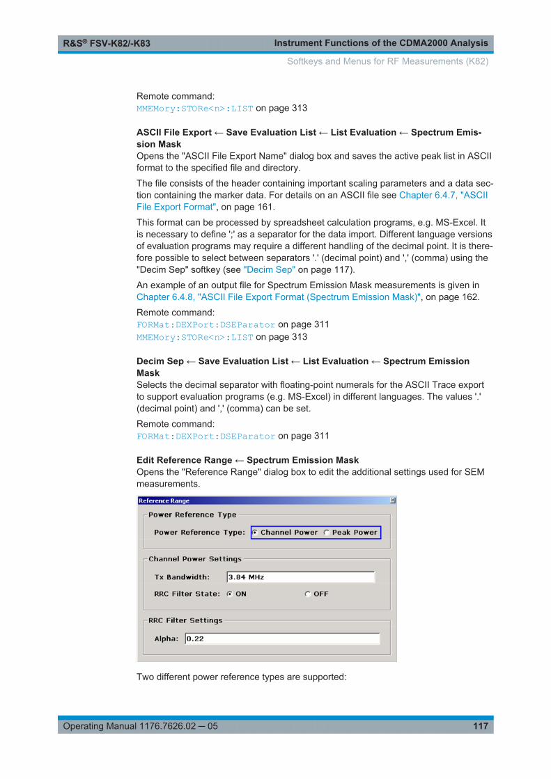
Instrument Functions of the CDMA2000 AnalysisR&S® FSV-K82/-K83
117Operating Manual 1176.7626.02 ─ 05
Remote command: MMEMory:STORe<n>:LIST on page 313
ASCII File Export ← Save Evaluation List ← List Evaluation ← Spectrum Emis-sion MaskOpens the "ASCII File Export Name" dialog box and saves the active peak list in ASCIIformat to the specified file and directory.
The file consists of the header containing important scaling parameters and a data sec-tion containing the marker data. For details on an ASCII file see Chapter 6.4.7, "ASCIIFile Export Format", on page 161.
This format can be processed by spreadsheet calculation programs, e.g. MS-Excel. Itis necessary to define ';' as a separator for the data import. Different language versionsof evaluation programs may require a different handling of the decimal point. It is there-fore possible to select between separators '.' (decimal point) and ',' (comma) using the"Decim Sep" softkey (see "Decim Sep" on page 117).
An example of an output file for Spectrum Emission Mask measurements is given inChapter 6.4.8, "ASCII File Export Format (Spectrum Emission Mask)", on page 162.
Remote command: FORMat:DEXPort:DSEParator on page 311MMEMory:STORe<n>:LIST on page 313
Decim Sep ← Save Evaluation List ← List Evaluation ← Spectrum EmissionMaskSelects the decimal separator with floating-point numerals for the ASCII Trace exportto support evaluation programs (e.g. MS-Excel) in different languages. The values '.'(decimal point) and ',' (comma) can be set.
Remote command: FORMat:DEXPort:DSEParator on page 311
Edit Reference Range ← Spectrum Emission MaskOpens the "Reference Range" dialog box to edit the additional settings used for SEMmeasurements.
Two different power reference types are supported:
Softkeys and Menus for RF Measurements (K82)

Instrument Functions of the CDMA2000 AnalysisR&S® FSV-K82/-K83
118Operating Manual 1176.7626.02 ─ 05
● "Peak Power"Measures the highest peak within the reference range.
● "Channel Power"Measures the channel power within the reference range (integral bandwidthmethod).If the "Channel Power" reference power type is activated, the dialog box is exten-ded to define additional settings:
● "Tx Bandwidth"Defines the bandwidth used for measuring the channel power:minimum span ≤ value ≤ span of reference range
● "RRC Filter State"Activates or deactivates the use of an RRC filter.
● "RRC Filter Settings"Sets the alpha value of the RRC filter. This window is only available if the RRC fil-ter is activated.
For further details refer to Chapter 6.4.11, "Ranges and Range Settings",on page 171.
Remote command: [SENSe:]ESPectrum:RTYPe on page 266[SENSe:]ESPectrum:BWID on page 255[SENSe:]ESPectrum:FILTer[:RRC][:STATe] on page 255[SENSe:]ESPectrum:FILTer[:RRC]:ALPHa on page 256
Edit Power Classes ← Spectrum Emission MaskOpens a dialog box to modify the power class settings.
Softkeys and Menus for RF Measurements (K82)

Instrument Functions of the CDMA2000 AnalysisR&S® FSV-K82/-K83
119Operating Manual 1176.7626.02 ─ 05
Used Power Classes ← Edit Power Classes ← Spectrum Emission MaskChoose the power classes to be used from this dropdown menu. It is only possible toselect either one of the defined power classes or all of the defined power classestogether.
Only power classes for which limits are defined are available for selection.
If "All" is selected, the power class that corresponds to the currently measured powerin the reference range is used. The limits assigned to that power class are applied (see"PMin/PMax" on page 119).
Remote command: CALCulate<n>:LIMit<k>:ESPectrum:PCLass<Class>[:EXCLusive]on page 207To define all limits in one step:CALCulate<n>:LIMit<k>:ESPectrum:PCLass<Class>:LIMit[:STATe]on page 208
PMin/PMax ← Edit Power Classes ← Spectrum Emission MaskDefines the level limits for each power class. The range always starts at -200 dBm (-INF) and always stops at 200 dBm (+INF). These fields cannot be modified. If morethan one Power Class is defined, the value of "PMin" must be equal to the value of"PMax" of the last Power Class and vice versa.
Note that the power level may be equal to the lower limit, but must be lower than theupper limit:
Pmin≦P<Pmax
Remote command: CALCulate<n>:LIMit<k>:ESPectrum:PCLass<Class>:MINimum on page 209CALCulate<n>:LIMit<k>:ESPectrum:PCLass<Class>:MAXimum on page 209
Sweep List ← Edit Power Classes ← Spectrum Emission MaskSee "Sweep List" on page 110
Add/Remove ← Edit Power Classes ← Spectrum Emission MaskActivates or deactivates power classes to be defined. Up to four power classes can bedefined. The number of active power classes affects the availability of the items of theUsed Power Classes dropdown menu.
Remote command: CALCulate<n>:LIMit<k>:ESPectrum:PCLass<Class>[:EXCLusive]on page 207
Bandclass ← Spectrum Emission MaskOpens a dialog box to select a specific bandclass.
For a list of predefined bandclasses refer to the "Bandclass" softkey in the ACP menu("Bandclass" on page 100.
The settings for each bandclass are provided in *.xml files that are located in the direc-tory C:\R_S\INSTR\sem_std\evdo\dl. The files themselves are namedDO_DL_BC01.XML (bandclass 1) to DO_DL_BC17.XML (bandclass 17). By selectingone of the bandclasses from the dialog box, the correct file is loaded automatically.The file can also be loaded manually (see Load Standard softkey).
Softkeys and Menus for RF Measurements (K82)

Instrument Functions of the CDMA2000 AnalysisR&S® FSV-K82/-K83
120Operating Manual 1176.7626.02 ─ 05
Remote command: CONFigure:CDPower[:BTS]:BCLass|BANDclass on page 225
Load Standard ← Spectrum Emission MaskOpens a dialog box to select an XML file which includes the desired standard specifi-cation. For details on the provided XML files refer to Chapter 6.4.10, "Provided XMLFiles for the Spectrum Emission Mask Measurement", on page 168.
Remote command: [SENSe:]ESPectrum:PRESet[:STANdard] on page 257
Save As Standard ← Spectrum Emission MaskOpens the "Save As Standard" dialog box, in which the currently used SEM settingsand parameters can be saved and exported into an *.xml file. Enter the name of the filein the "File name" field. For details on the structure and contents of the XML file refer toChapter 6.4.9, "Format Description of Spectrum Emission Mask XML Files",on page 163.
Remote command: [SENSe:]ESPectrum:PRESet:STORe on page 257
Meas Start/Stop ← Spectrum Emission MaskAborts/restarts the current measurement and displays the status:
"Start" The measurement is currently running.
"Stop" The measurement has been stopped, or, in single sweep mode, theend of the sweep has been reached.
Remote command: ABORt on page 310INITiate<n>:ESPectrum on page 312
Restore Standard Files ← Spectrum Emission MaskCopies the XML files from the C:\R_S\instr\sem_backup folder to the C:\R_S\instr\sem_std folder. Files of the same name are overwritten.
Remote command: [SENSe:]ESPectrum:PRESet:RESTore on page 257
Occupied BandwidthActivates measurement of the bandwidth assigned to the signal.
Remote command: CONFigure:CDPower[:BTS]:MEASurement on page 234CALCulate<n>:MARKer<m>:FUNCtion:POWer:RESult? on page 187
% Power Bandwidth (span > 0) ← Occupied BandwidthOpens an edit dialog box to enter the percentage of total power in the displayed fre-quency range which defines the occupied bandwidth. Values from 10% to 99.9% areallowed.
Softkeys and Menus for RF Measurements (K82)

Instrument Functions of the CDMA2000 AnalysisR&S® FSV-K82/-K83
121Operating Manual 1176.7626.02 ─ 05
Remote command: [SENSe:]POWer:BANDwidth|BWIDth on page 282
Channel Bandwidth (span > 0) ← Occupied BandwidthOpens an edit dialog box to enter the channel bandwidth for the transmission channel.The specified channel bandwidth is used for optimization of the test parameters (fordetails see Chapter 6.4.14, "Optimized Settings for CP/ACLR Test Parameters",on page 175). The default setting is 14 kHz.
For measurements in line with a specific transmission standard, the bandwidth speci-fied by the standard for the transmission channel must be entered.
Remote command: [SENSe:]POWer:ACHannel:BANDwidth|BWIDth[:CHANnel<channel>]on page 274
Adjust Ref Lvl (span > 0) ← Occupied BandwidthAdjusts the reference level to the measured total power of the signal. the softkey isactivated after the first sweep with active measurement of the occupied bandwidth hasbeen completed and the total power of the signal is thus known.
Adjusting the reference level ensures that the signal path will not be overloaded andthe dynamic range not limited by too low a reference level. Since the measurementbandwidth for channel power measurements is significantly lower than the signal band-width, the signal path may be overloaded although the trace is distinctly below the ref-erence level. If the measured channel power is equal to the reference level, the signalpath cannot be overloaded.
Remote command: [SENSe:]POWer:ACHannel:PRESet:RLEVel on page 279
Adjust Settings ← Occupied BandwidthAutomatically optimizes all instrument settings for the selected channel configuration(channel bandwidth, channel spacing) within a specific frequency range (channel band-width). The adjustment is carried out only once. If necessary, the instrument settingscan be changed later.
For details on the settings of span, resolution bandwidth, video bandwidth, detectorand trace averaging see Chapter 6.4.14, "Optimized Settings for CP/ACLR TestParameters", on page 175.
Remote command: [SENSe:]POWer:ACHannel:PRESet on page 278
CCDFStarts the measurement of the Complementary Cumulative Distribution Function andthe Crest factor.
Also opens the CCDF submenu containing the following softkeys:
Remote command: CONFigure:CDPower[:BTS]:MEASurement on page 234
Res BW ← CCDFOpens an edit dialog box to set the resolution bandwidth directly.
Softkeys and Menus for RF Measurements (K82)

Instrument Functions of the CDMA2000 AnalysisR&S® FSV-K82/-K83
122Operating Manual 1176.7626.02 ─ 05
For correct measurement of the signal statistics the resolution bandwidth has to bewider than the signal bandwidth in order to measure the actual peaks of the signalamplitude correctly. In order not to influence the peak amplitudes the video bandwidthis automatically set to 10 MHz. The sample detector is used for detecting the videovoltage.
Remote command: [SENSe:]BANDwidth|BWIDth[:RESolution] on page 266
# of Samples ← CCDFOpens an edit dialog box to set the number of power measurements that are taken intoaccount for the statistics.
Apart from the number of measurements the overall measurement time depends alsoon the set resolution bandwidth as the resolution bandwidth directly influences thesampling rate.
Remote command: CALCulate<n>:STATistics:NSAMples on page 220
Scaling ← CCDFOpens a submenu to change the scaling parameters of x- and y-axis.
x-Axis Ref Level ← Scaling ← CCDFOpens an edit dialog box to enter the reference level in the currently active unit (dBm,dBµV, etc). The function of this softkey is identical to the "Ref Level" softkey in the"Amplitude" menu (see "Ref Level" on page 62).
For the APD function this value is mapped to the right diagram border. For the CCDFfunction there is no direct representation of this value on the diagram as the x-axis isscaled relatively to the measured mean power.
Remote command: CALCulate<n>:STATistics:SCALe:X:RLEVel on page 222
x-Axis Range ← Scaling ← CCDFOpens the "Range" submenu to select a value for the level range to be covered by thestatistics measurement selected.
Remote command: CALCulate<n>:STATistics:SCALe:X:RANGe on page 221
Range Log 100 dB ← x-Axis Range ← Scaling ← CCDFSets the level display range to 100 dB.
Remote command: Logarithmic scaling:DISP:WIND:TRAC:Y:SPAC LOG, see DISPlay[:WINDow<n>]:TRACe<t>:Y:SPACing on page 241Display range:DISP:WIND:TRAC:Y 100DB, see DISPlay[:WINDow<n>]:TRACe<t>:Y[:SCALe]on page 238
Softkeys and Menus for RF Measurements (K82)

Instrument Functions of the CDMA2000 AnalysisR&S® FSV-K82/-K83
123Operating Manual 1176.7626.02 ─ 05
Range Log 50 dB ← x-Axis Range ← Scaling ← CCDFSets the level display range to 50 dB.
Remote command: Logarithmic scaling:DISP:WIND:TRAC:Y:SPAC LOG, see DISPlay[:WINDow<n>]:TRACe<t>:Y:SPACing on page 241Display range:DISP:WIND:TRAC:Y 50DB, see DISPlay[:WINDow<n>]:TRACe<t>:Y[:SCALe]on page 238
Range Log 10 dB ← x-Axis Range ← Scaling ← CCDFSets the level display range to 10 dB.
Remote command: Logarithmic scaling:DISP:WIND:TRAC:Y:SPAC LOG, see DISPlay[:WINDow<n>]:TRACe<t>:Y:SPACing on page 241Display range:DISP:WIND:TRAC:Y 10DB, see DISPlay[:WINDow<n>]:TRACe<t>:Y[:SCALe]on page 238
Range Log 5 dB ← x-Axis Range ← Scaling ← CCDFSets the level display range to 5 dB.
Remote command: Logarithmic scaling:DISP:WIND:TRAC:Y:SPAC LOG, see DISPlay[:WINDow<n>]:TRACe<t>:Y:SPACing on page 241Display range:DISP:WIND:TRAC:Y 5DB, see DISPlay[:WINDow<n>]:TRACe<t>:Y[:SCALe]on page 238
Range Log 1 dB ← x-Axis Range ← Scaling ← CCDFSets the level display range to 1 dB.
Remote command: Logarithmic scaling:DISP:WIND:TRAC:Y:SPAC LOG, see DISPlay[:WINDow<n>]:TRACe<t>:Y:SPACing on page 241Display range:DISP:WIND:TRAC:Y 1DB, see DISPlay[:WINDow<n>]:TRACe<t>:Y[:SCALe]on page 238
Range Log Manual ← x-Axis Range ← Scaling ← CCDFOpens an edit dialog box to define the display range of a logarithmic level axis man-ually.
Remote command: Logarithmic scaling:DISP:WIND:TRAC:Y:SPAC LOG, see DISPlay[:WINDow<n>]:TRACe<t>:Y:SPACing on page 241
Softkeys and Menus for RF Measurements (K82)

Instrument Functions of the CDMA2000 AnalysisR&S® FSV-K82/-K83
124Operating Manual 1176.7626.02 ─ 05
Display range:DISPlay[:WINDow<n>]:TRACe<t>:Y[:SCALe] on page 238
Range Linear % ← x-Axis Range ← Scaling ← CCDFSelects linear scaling for the level axis in %.
The grid is divided into decadal sections.
Markers are displayed in the selected unit ("Unit" softkey). Delta markers are displayedin % referenced to the voltage value at the position of marker 1. This is the default set-ting for linear scaling.
Remote command: DISP:TRAC:Y:SPAC LIN, see DISPlay[:WINDow<n>]:TRACe<t>:Y:SPACingon page 241
Range Lin. Unit ← x-Axis Range ← Scaling ← CCDFSelects linear scaling in dB for the level display range, i.e. the horizontal lines arelabeled in dB.
Markers are displayed in the selected unit ("Unit" softkey). Delta markers are displayedin dB referenced to the power value at the position of marker 1.
Remote command: DISP:TRAC:Y:SPAC LDB, see DISPlay[:WINDow<n>]:TRACe<t>:Y:SPACingon page 241
y-Axis Max Value ← Scaling ← CCDFOpens an edit dialog box to define the upper limit of the displayed probability range.Values on the y-axis are normalized which means that the maximum value is 1.0. They-axis scaling is defined via the y-Unit % / Abs softkey. The distance between max andmin value must be at least one decade.
Remote command: CALCulate<n>:STATistics:SCALe:Y:UPPer on page 223
y-Axis Min Value ← Scaling ← CCDFOpens an edit dialog box to define the lower limit of the displayed probability range.Values in the range 1e-9 < value < 0.1 are allowed. The y-axis scaling is defined via they-Unit % / Abs softkey. The distance between max and min value must be at least onedecade.
Remote command: CALCulate<n>:STATistics:SCALe:Y:LOWer on page 222
y-Unit % / Abs ← Scaling ← CCDFDefines the scaling type of the y-axis. The default value is absolute scaling.
Remote command: CALCulate<n>:STATistics:SCALe:Y:UNIT on page 222
Default Settings ← Scaling ← CCDFResets the x- and y-axis scalings to their preset values.
Softkeys and Menus for RF Measurements (K82)

Instrument Functions of the CDMA2000 AnalysisR&S® FSV-K82/-K83
125Operating Manual 1176.7626.02 ─ 05
x-axis ref level: -10 dBm
x-axis range APD: 100 dB
x-axis range CCDF: 20 dB
y-axis upper limit: 1.0
y-axis lower limit: 1E-6
Remote command: CALCulate<n>:STATistics:PRESet on page 220
Adjust Settings ← Scaling ← CCDFAdjusts the level settings according to the measured difference between peak and min-imum power for APD measurement or peak and mean power for CCDF measurementin order to obtain maximum power resolution. Adjusts the reference level to the currentinput signal. For details see also the Adjust Ref Lvl softkey.
Remote command: CALCulate<n>:STATistics:SCALe:AUTO ONCE on page 221
Gated Trigger (On/Off) ← CCDFActivates and deactivates the gating for statistics functions for the ACP and the CCDFchannel. The trigger source is changed to "EXTERN" if this function is switched on.The gate ranges are defined using the "Gate Ranges" on page 125 softkey.
Remote command: [SENSe:]SWEep:EGATe on page 284[SENSe:]SWEep:EGATe:SOURce on page 285
Gate Ranges ← CCDFOpens a dialog to configure up to 3 gate ranges for each trace.
Remote command: SWE:EGAT ON (see [SENSe:]SWEep:EGATe on page 284)Switches on the external gate mode.SWE:EGAT:TRAC1:COMM "SlotA" (see [SENSe:]SWEep:EGATe:TRACe<k>:COMMent on page 286)
Softkeys and Menus for RF Measurements (K82)
Instrument Functions of the CDMA2000 AnalysisR&S® FSV-K82/-K83
126Operating Manual 1176.7626.02 ─ 05
Adds a comment to trace 1.SWE:EGAT:TRAC1:STAT1 ON (see [SENSe:]SWEep:EGATe:TRACe<k>[:STATe<range>] on page 287)Activates tracing for range 1 of trace 1.SWE:EGAT:TRAC1:STAR1 3ms (see [SENSe:]SWEep:EGATe:TRACe<k>:STARt<range> on page 286)Sets the starting point for range 1 on trace 1 at 3 ms.SWE:EGAT:TRAC1:STop1 5ms (see [SENSe:]SWEep:EGATe:TRACe<k>:STOP<range> on page 287)Sets the stopping point for range 1 on trace 1 at 5 ms.SWE:EGAT:TRAC1:PER 5ms (see [SENSe:]SWEep:EGATe:TRACe<k>: PERiodon page 286)Defines the period for gated triggering to 5 ms.
Adjust Settings ← CCDFAdjusts the level settings according to the measured difference between peak and min-imum power for APD measurement or peak and mean power for CCDF measurementin order to obtain maximum power resolution. Adjusts the reference level to the currentinput signal. For details see also the Adjust Ref Lvl softkey.
Remote command: CALCulate<n>:STATistics:SCALe:AUTO ONCE on page 221
6.3.2 Softkeys of the Frequency Menu
The following chapter describes all softkeys available in the "Frequency" menu. It ispossible that your instrument configuration does not provide all softkeys. If a softkey isonly available with a special option, model or (measurement) mode, this information isprovided in the corresponding softkey description.
Center......................................................................................................................... 126CF Stepsize.................................................................................................................127
└ 0.1*Span (span > 0)......................................................................................127└ 0.1*RBW (span > 0)......................................................................................127└ 0.5*Span (span > 0)......................................................................................127└ 0.5*RBW (span > 0)......................................................................................127└ x*Span (span > 0)......................................................................................... 128└ x*RBW (span > 0)......................................................................................... 128└ =Center......................................................................................................... 128└ =Marker.........................................................................................................128└ Manual.......................................................................................................... 128
Start.............................................................................................................................128Stop.............................................................................................................................129Frequency Offset.........................................................................................................129
CenterOpens an edit dialog box to enter the center frequency. The allowed range of valuesfor the center frequency depends on the frequency span.
span > 0: spanmin/2 ≤ fcenter ≤ fmax – spanmin/2
Softkeys and Menus for RF Measurements (K82)
Instrument Functions of the CDMA2000 AnalysisR&S® FSV-K82/-K83
127Operating Manual 1176.7626.02 ─ 05
span = 0: 0 Hz ≤ fcenter ≤ fmax
fmax and spanmin are specified in the data sheet.
If the bandwidth extension option R&S FSV-B160 is active, center frequencies above7 GHz are not available.
Remote command: [SENSe:]FREQuency:CENTer on page 270
CF StepsizeOpens a submenu to set the step size of the center frequency.
The step size defines the value by which the center frequency is increased ordecreased when the arrow keys are pressed. When you use the rotary knob the centerfrequency changes in steps of 10% of the "Center Frequency Stepsize".
The step size can be set to a fraction of the span (span > 0) or a fraction of the resolu-tion bandwidth (span = 0) or it can be set to a fixed value manually.
Apart from the =Center, =Marker and Manual softkeys, the other softkeys are dis-played depending on the selected frequency span.
This softkey is available for RF measurements.
0.1*Span (span > 0) ← CF StepsizeSets the step size for the center frequency to 10 % of the span.
Remote command: FREQ:CENT:STEP:LINK SPAN, see [SENSe:]FREQuency:CENTer:STEP:LINKon page 271FREQ:CENT:STEP:LINK:FACT 10PCT, see [SENSe:]FREQuency:CENTer:STEP:LINK:FACTor on page 271
0.1*RBW (span > 0) ← CF StepsizeSets the step size for the center frequency to 10 % of the resolution bandwidth.
This is the default setting.
Remote command: FREQ:CENT:STEP:LINK RBW, see [SENSe:]FREQuency:CENTer:STEP:LINKon page 271FREQ:CENT:STEP:LINK:FACT 10PCT, see [SENSe:]FREQuency:CENTer:STEP:LINK:FACTor on page 271
0.5*Span (span > 0) ← CF StepsizeSets the step size for the center frequency to 50 % of the span.
Remote command: FREQ:CENT:STEP:LINK SPAN, see [SENSe:]FREQuency:CENTer:STEP:LINKon page 271FREQ:CENT:STEP:LINK:FACT 50PCT, see [SENSe:]FREQuency:CENTer:STEP:LINK:FACTor on page 271
0.5*RBW (span > 0) ← CF StepsizeSets the step size for the center frequency to 50 % of the resolution bandwidth.
Softkeys and Menus for RF Measurements (K82)
Instrument Functions of the CDMA2000 AnalysisR&S® FSV-K82/-K83
128Operating Manual 1176.7626.02 ─ 05
Remote command: FREQ:CENT:STEP:LINK RBW, see [SENSe:]FREQuency:CENTer:STEP:LINKon page 271FREQ:CENT:STEP:LINK:FACT 50PCT, see [SENSe:]FREQuency:CENTer:STEP:LINK:FACTor on page 271
x*Span (span > 0) ← CF StepsizeOpens an edit dialog box to set the step size for the center frequency as a percentage(%) of the span.
Remote command: FREQ:CENT:STEP:LINK SPAN, see [SENSe:]FREQuency:CENTer:STEP:LINKon page 271FREQ:CENT:STEP:LINK:FACT 20PCT, see [SENSe:]FREQuency:CENTer:STEP:LINK on page 271
x*RBW (span > 0) ← CF StepsizeOpens an edit dialog box to set the step size for the center frequency as a percentage(%) of the resolution bandwidth. Values between 1 % and 100 % in steps of 1 % areallowed. The default setting is 10 %.
Remote command: FREQ:CENT:STEP:LINK RBW, see [SENSe:]FREQuency:CENTer:STEP:LINKon page 271FREQ:CENT:STEP:LINK:FACT 20PCT, see [SENSe:]FREQuency:CENTer:STEP:LINK on page 271
=Center ← CF StepsizeSets the step size to the value of the center frequency and removes the coupling of thestep size to span or resolution bandwidth.
This function is especially useful for measurements of the signal harmonics. In thiscase, each stroke of the arrow key selects the center frequency of another harmonic.
=Marker ← CF StepsizeSets the step size to the value of the current marker and removes the coupling of thestep size to span or resolution bandwidth.
This function is especially useful for measurements of the signal harmonics. In thiscase, each stroke of the arrow key selects the center frequency of another harmonic.
Manual ← CF StepsizeOpens an edit dialog box to enter a fixed step size for the center frequency.
Remote command: [SENSe:]FREQuency:CENTer:STEP on page 270
StartOpens an edit dialog box to define the start frequency. The following range of values isallowed:
fmin ≤ fstart ≤ fmax – spanmin
fmin, fmax and spanmin are specified in the data sheet.
Softkeys and Menus for RF Measurements (K82)

Instrument Functions of the CDMA2000 AnalysisR&S® FSV-K82/-K83
129Operating Manual 1176.7626.02 ─ 05
Remote command: [SENSe:]FREQuency:STARt on page 272
StopOpens an edit dialog box to define the stop frequency. The following range of valuesfor the stop frequency is allowed:
fmin + spanmin ≤ fstop ≤ fmax
f min , f max and spanmin are specified in the data sheet.
Remote command: [SENSe:]FREQuency:STOP on page 273
Frequency OffsetOpens an edit dialog box to enter a frequency offset that shifts the displayed frequencyrange by the specified offset.
The softkey indicates the current frequency offset. The allowed values range from-100 GHz to 100 GHz. The default setting is 0 Hz.
Remote command: [SENSe:]FREQuency:OFFSet on page 272
6.3.3 Softkeys of the Span Menu for RF Measurements
The following chapter describes all softkeys available in the "Span" menu for RF mea-surements, except for "Power" measurements.
Span Manual............................................................................................................... 129Sweeptime Manual......................................................................................................129Full Span..................................................................................................................... 130Last Span.................................................................................................................... 130
Span ManualOpens an edit dialog box to enter the frequency span. The center frequency remainsthe same when you change the span.
The following range is allowed:
span = 0: 0 Hz
span >0: spanmin ≤ f span ≤ f max
fmax and spanmin are specified in the data sheet.
Remote command: [SENSe:]FREQuency:SPAN on page 272
Sweeptime ManualOpens an edit dialog box to enter the sweep time.
Softkeys and Menus for RF Measurements (K82)
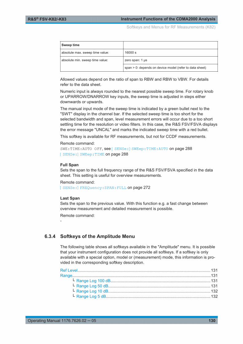
Instrument Functions of the CDMA2000 AnalysisR&S® FSV-K82/-K83
130Operating Manual 1176.7626.02 ─ 05
Sweep time
absolute max. sweep time value: 16000 s
absolute min. sweep time value: zero span: 1 μs
span > 0: depends on device model (refer to data sheet)
Allowed values depend on the ratio of span to RBW and RBW to VBW. For detailsrefer to the data sheet.
Numeric input is always rounded to the nearest possible sweep time. For rotary knobor UPARROW/DNARROW key inputs, the sweep time is adjusted in steps eitherdownwards or upwards.
The manual input mode of the sweep time is indicated by a green bullet next to the"SWT" display in the channel bar. If the selected sweep time is too short for theselected bandwidth and span, level measurement errors will occur due to a too shortsettling time for the resolution or video filters. In this case, the R&S FSV/FSVA displaysthe error message "UNCAL" and marks the indicated sweep time with a red bullet.
This softkey is available for RF measurements, but not for CCDF measurements.
Remote command: SWE:TIME:AUTO OFF, see [SENSe:]SWEep:TIME:AUTO on page 288[SENSe:]SWEep:TIME on page 288
Full SpanSets the span to the full frequency range of the R&S FSV/FSVA specified in the datasheet. This setting is useful for overview measurements.
Remote command: [SENSe:]FREQuency:SPAN:FULL on page 272
Last SpanSets the span to the previous value. With this function e.g. a fast change betweenoverview measurement and detailed measurement is possible.
Remote command: -
6.3.4 Softkeys of the Amplitude Menu
The following table shows all softkeys available in the "Amplitude" menu. It is possiblethat your instrument configuration does not provide all softkeys. If a softkey is onlyavailable with a special option, model or (measurement) mode, this information is pro-vided in the corresponding softkey description.
Ref Level..................................................................................................................... 131Range..........................................................................................................................131
└ Range Log 100 dB........................................................................................131└ Range Log 50 dB..........................................................................................131└ Range Log 10 dB..........................................................................................132└ Range Log 5 dB............................................................................................132
Softkeys and Menus for RF Measurements (K82)

Instrument Functions of the CDMA2000 AnalysisR&S® FSV-K82/-K83
131Operating Manual 1176.7626.02 ─ 05
└ Range Log 1 dB............................................................................................132└ Range Log Manual........................................................................................132└ Range Linear %............................................................................................ 132└ Range Lin. Unit............................................................................................. 133
Unit..............................................................................................................................133Preamp On/Off............................................................................................................ 133RF Atten Manual/Mech Att Manual............................................................................. 134RF Atten Auto/Mech Att Auto...................................................................................... 134El Atten On/Off............................................................................................................ 134El Atten Mode (Auto/Man)...........................................................................................135Ref Level Offset.......................................................................................................... 135Ref Level Position....................................................................................................... 135Grid Abs/Rel ...............................................................................................................135Noise Correction......................................................................................................... 136Input (AC/DC)..............................................................................................................136Input 50 Ω/75 Ω ..........................................................................................................136(Bypassing the ) YIG Filter.......................................................................................... 137
Ref LevelOpens an edit dialog box to enter the reference level in the current unit (dBm, dBµV,etc).
The reference level is the maximum value the AD converter can handle without distor-tion of the measured value. Signal levels above this value will not be measured cor-rectly, which is indicated by the "IFOVL" status display.
Remote command: DISPlay[:WINDow<n>]:TRACe<t>:Y[:SCALe]:RLEVel on page 239
RangeOpens a submenu to define the display range of the level axis.
This softkey and its submenu are available for RF measurements.
Range Log 100 dB ← RangeSets the level display range to 100 dB.
Remote command: Logarithmic scaling:DISP:WIND:TRAC:Y:SPAC LOG, see DISPlay[:WINDow<n>]:TRACe<t>:Y:SPACing on page 241Display range:DISP:WIND:TRAC:Y 100DB, see DISPlay[:WINDow<n>]:TRACe<t>:Y[:SCALe]on page 238
Range Log 50 dB ← RangeSets the level display range to 50 dB.
Remote command: Logarithmic scaling:DISP:WIND:TRAC:Y:SPAC LOG, see DISPlay[:WINDow<n>]:TRACe<t>:Y:SPACing on page 241
Softkeys and Menus for RF Measurements (K82)

Instrument Functions of the CDMA2000 AnalysisR&S® FSV-K82/-K83
132Operating Manual 1176.7626.02 ─ 05
Display range:DISP:WIND:TRAC:Y 50DB, see DISPlay[:WINDow<n>]:TRACe<t>:Y[:SCALe]on page 238
Range Log 10 dB ← RangeSets the level display range to 10 dB.
Remote command: Logarithmic scaling:DISP:WIND:TRAC:Y:SPAC LOG, see DISPlay[:WINDow<n>]:TRACe<t>:Y:SPACing on page 241Display range:DISP:WIND:TRAC:Y 10DB, see DISPlay[:WINDow<n>]:TRACe<t>:Y[:SCALe]on page 238
Range Log 5 dB ← RangeSets the level display range to 5 dB.
Remote command: Logarithmic scaling:DISP:WIND:TRAC:Y:SPAC LOG, see DISPlay[:WINDow<n>]:TRACe<t>:Y:SPACing on page 241Display range:DISP:WIND:TRAC:Y 5DB, see DISPlay[:WINDow<n>]:TRACe<t>:Y[:SCALe]on page 238
Range Log 1 dB ← RangeSets the level display range to 1 dB.
Remote command: Logarithmic scaling:DISP:WIND:TRAC:Y:SPAC LOG, see DISPlay[:WINDow<n>]:TRACe<t>:Y:SPACing on page 241Display range:DISP:WIND:TRAC:Y 1DB, see DISPlay[:WINDow<n>]:TRACe<t>:Y[:SCALe]on page 238
Range Log Manual ← RangeOpens an edit dialog box to define the display range of a logarithmic level axis man-ually.
Remote command: Logarithmic scaling:DISP:WIND:TRAC:Y:SPAC LOG, see DISPlay[:WINDow<n>]:TRACe<t>:Y:SPACing on page 241Display range:DISPlay[:WINDow<n>]:TRACe<t>:Y[:SCALe] on page 238
Range Linear % ← RangeSelects linear scaling for the level axis in %.
The grid is divided into decadal sections.
Softkeys and Menus for RF Measurements (K82)

Instrument Functions of the CDMA2000 AnalysisR&S® FSV-K82/-K83
133Operating Manual 1176.7626.02 ─ 05
Markers are displayed in the selected unit ("Unit" softkey). Delta markers are displayedin % referenced to the voltage value at the position of marker 1. This is the default set-ting for linear scaling.
Remote command: DISP:TRAC:Y:SPAC LIN, see DISPlay[:WINDow<n>]:TRACe<t>:Y:SPACingon page 241
Range Lin. Unit ← RangeSelects linear scaling in dB for the level display range, i.e. the horizontal lines arelabeled in dB.
Markers are displayed in the selected unit ("Unit" softkey). Delta markers are displayedin dB referenced to the power value at the position of marker 1.
Remote command: DISP:TRAC:Y:SPAC LDB, see DISPlay[:WINDow<n>]:TRACe<t>:Y:SPACingon page 241
UnitOpens the "Unit" submenu to select the unit for the level axis.
The default setting is dBm.
If a transducer is switched on, the softkey is not available.
In general, the signal analyzer measures the signal voltage at the RF input. The leveldisplay is calibrated in RMS values of an unmodulated sine wave signal. In the defaultstate, the level is displayed at a power of 1 mW (= dBm). Via the known input impe-dance (50 Ω or 75 Ω), conversion to other units is possible. The following units areavailable and directly convertible:● dBm● dBmV● dBμV● dBμA● dBpW● Volt● Ampere● Watt
Remote command: CALCulate<n>:UNIT:POWer on page 224
Preamp On/OffSwitches the preamplifier on and off.
If option R&S FSV-B22 is installed, the preamplifier is only active below 7 GHz.
If option R&S FSV-B24 is installed, the preamplifier is active for all frequencies.
This function is not available for input from the R&S Digital I/Q Interface (optionR&S FSV-B17).
Softkeys and Menus for RF Measurements (K82)

Instrument Functions of the CDMA2000 AnalysisR&S® FSV-K82/-K83
134Operating Manual 1176.7626.02 ─ 05
Remote command: INPut:GAIN:STATe on page 306
RF Atten Manual/Mech Att ManualOpens an edit dialog box to enter the attenuation, irrespective of the reference level. Ifelectronic attenuation is activated (option R&S FSV-B25 only; "El Atten Mode Auto"softkey), this setting defines the mechanical attenuation.
The mechanical attenuation can be set in 10 dB steps.
The RF attenuation can be set in 5 dB steps (R&S FSV with option R&S FSV-B25 orR&S FSVA: 1 dB steps). The range is specified in the data sheet. If the current refer-ence level cannot be set for the set RF attenuation, the reference level is adjustedaccordingly.
This function is not available for input from the R&S Digital I/Q Interface (optionR&S FSV-B17).
The RF attenuation defines the level at the input mixer according to the formula:
levelmixer = levelinput – RF attenuation
Note: As of firmware version 1.61, the maximum mixer level allowed is 0 dBm. Mixerlevels above this value may lead to incorrect measurement results, which are indicatedby the "OVLD" status display. The increased mixer level allows for an improved signal,but also increases the risk of overloading the instrument!
Remote command: INPut:ATTenuation on page 300
RF Atten Auto/Mech Att AutoSets the RF attenuation automatically as a function of the selected reference level.This ensures that the optimum RF attenuation is always used. It is the default setting.
This function is not available for input from the R&S Digital I/Q Interface (optionR&S FSV-B17).
Remote command: INPut:ATTenuation:AUTO on page 300
El Atten On/OffThis softkey switches the electronic attenuator on or off. This softkey is only availablewith option R&S FSV-B25.
When the electronic attenuator is activated, the mechanical and electronic attenuationcan be defined separately. Note however, that both parts must be defined in the samemode, i.e. either both manually, or both automatically.
This function is not available for input from the R&S Digital I/Q Interface (optionR&S FSV-B17).
● To define the mechanical attenuation, use the RF Atten Manual/Mech Att Manualor RF Atten Auto/Mech Att Auto softkeys.
● To define the electronic attenuation, use the El Atten Mode (Auto/Man) softkey.Note: This function is not available for stop frequencies (or center frequencies in zerospan) >7 GHz. In this case, the electronic and mechanical attenuation are summarized
Softkeys and Menus for RF Measurements (K82)

Instrument Functions of the CDMA2000 AnalysisR&S® FSV-K82/-K83
135Operating Manual 1176.7626.02 ─ 05
and the electronic attenuation can no longer be defined individually. As soon as thestop or center frequency is reduced below 7 GHz, this function is available again.When the electronic attenuator is switched off, the corresponding RF attenuation mode(auto/manual) is automatically activated.
Remote command: INPut:EATT:AUTO on page 305
El Atten Mode (Auto/Man)This softkey defines whether the electronic attenuator value is to be set automaticallyor manually. If manual mode is selected, an edit dialog box is opened to enter thevalue. This softkey is only available with option R&S FSV-B25, and only if the elec-tronic attenuator has been activated via the El Atten On/Off softkey.
Note: This function is not available for stop frequencies (or center frequencies in zerospan) >7 GHz. In this case, the electronic and mechanical attenuation are summarizedand the electronic attenuation can no longer be defined individually. As soon as thestop or center frequency is reduced below 7 GHz, electronic attenuation is availableagain. If the electronic attenuation was defined manually, it must be re-defined.The attenuation can be varied in 1 dB steps from 0 to 30 dB. Other entries are roundedto the next lower integer value.
To re-open the edit dialog box for manual value definition, select the "Man" modeagain.
If the defined reference level cannot be set for the given RF attenuation, the referencelevel is adjusted accordingly and the warning "Limit reached" is output.
Remote command: INPut:EATT:AUTO on page 305INPut:EATT on page 305
Ref Level OffsetOpens an edit dialog box to enter the arithmetic level offset. This offset is added to themeasured level irrespective of the selected unit. The scaling of the y-axis is changedaccordingly. The setting range is ±200 dB in 0.1 dB steps.
Remote command: DISPlay[:WINDow<n>]:TRACe<t>:Y[:SCALe]:RLEVel:OFFSet on page 240
Ref Level PositionOpens an edit dialog box to enter the reference level position, i.e. the position of themaximum AD converter value on the level axis. The setting range is from -200 to+200 %, 0 % corresponding to the lower and 100 % to the upper limit of the diagram.
Only available for RF measurements.
Remote command: DISPlay[:WINDow<n>]:TRACe<t>:Y[:SCALe]:RPOSition on page 240
Grid Abs/RelSwitches between absolute and relative scaling of the level axis (not available with"Linear" range).
Only available for RF measurements.
Softkeys and Menus for RF Measurements (K82)
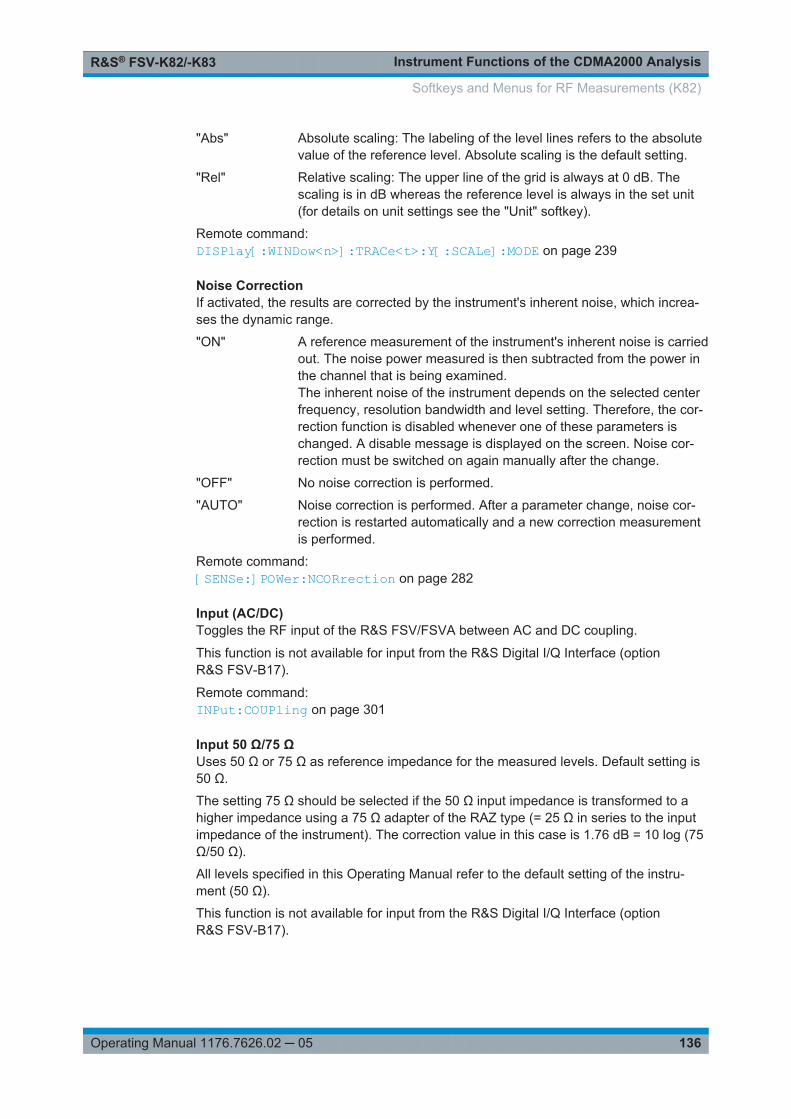
Instrument Functions of the CDMA2000 AnalysisR&S® FSV-K82/-K83
136Operating Manual 1176.7626.02 ─ 05
"Abs" Absolute scaling: The labeling of the level lines refers to the absolutevalue of the reference level. Absolute scaling is the default setting.
"Rel" Relative scaling: The upper line of the grid is always at 0 dB. Thescaling is in dB whereas the reference level is always in the set unit(for details on unit settings see the "Unit" softkey).
Remote command: DISPlay[:WINDow<n>]:TRACe<t>:Y[:SCALe]:MODE on page 239
Noise CorrectionIf activated, the results are corrected by the instrument's inherent noise, which increa-ses the dynamic range.
"ON" A reference measurement of the instrument's inherent noise is carriedout. The noise power measured is then subtracted from the power inthe channel that is being examined.The inherent noise of the instrument depends on the selected centerfrequency, resolution bandwidth and level setting. Therefore, the cor-rection function is disabled whenever one of these parameters ischanged. A disable message is displayed on the screen. Noise cor-rection must be switched on again manually after the change.
"OFF" No noise correction is performed.
"AUTO" Noise correction is performed. After a parameter change, noise cor-rection is restarted automatically and a new correction measurementis performed.
Remote command: [SENSe:]POWer:NCORrection on page 282
Input (AC/DC)Toggles the RF input of the R&S FSV/FSVA between AC and DC coupling.
This function is not available for input from the R&S Digital I/Q Interface (optionR&S FSV-B17).
Remote command: INPut:COUPling on page 301
Input 50 Ω/75 ΩUses 50 Ω or 75 Ω as reference impedance for the measured levels. Default setting is50 Ω.
The setting 75 Ω should be selected if the 50 Ω input impedance is transformed to ahigher impedance using a 75 Ω adapter of the RAZ type (= 25 Ω in series to the inputimpedance of the instrument). The correction value in this case is 1.76 dB = 10 log (75Ω/50 Ω).
All levels specified in this Operating Manual refer to the default setting of the instru-ment (50 Ω).
This function is not available for input from the R&S Digital I/Q Interface (optionR&S FSV-B17).
Softkeys and Menus for RF Measurements (K82)

Instrument Functions of the CDMA2000 AnalysisR&S® FSV-K82/-K83
137Operating Manual 1176.7626.02 ─ 05
Remote command: INPut:IMPedance on page 306
(Bypassing the ) YIG FilterIf the option R&S FSVA-B11 is installed, the YIG preselector can be bypassed.
This function is only available for R&S FSVA instruments.
If the YIG preselector at the input of the R&S FSVA is removed from the signal path,you can use the maximum bandwidth for signal analysis. However, image-frequencyrejection is no longer ensured.
Note that the YIG preselector is active only on frequencies greater than 7 GHz. There-fore, switching the YIG preselector on and off has no effect if the frequency is belowthat value.
Note:For the following measurements, the YIG preselector is off by default (if available).● I/Q Analyzer● GSM● VSAINPut:FILTer:YIG[:STATe] on page 306
6.3.5 Softkeys of the Bandwidth Menu
The following table shows all softkeys available in the "Bandwidth" menu. It is possiblethat your instrument configuration does not provide all softkeys. If a softkey is onlyavailable with a special option, model or (measurement) mode, this information is pro-vided in the corresponding softkey description.
For Spurious Emission Measurements, the settings are defined in the "Sweep List" dia-log, see the description in the base unit.Bandwidth settings are only available for RF measurements.
Res BW Manual.......................................................................................................... 138Res BW Auto...............................................................................................................138Video BW Manual....................................................................................................... 138Video BW Auto............................................................................................................139Sweeptime Manual......................................................................................................139Sweeptime Auto.......................................................................................................... 140Sweep Type................................................................................................................ 140
└ Sweep...........................................................................................................140└ FFT............................................................................................................... 140└ Auto...............................................................................................................141└ FFT Filter Mode............................................................................................ 141
└ Auto.................................................................................................... 141└ Narrow................................................................................................ 141
Coupling Ratio.............................................................................................................141└ RBW/VBW Sine [1/1].................................................................................... 141└ RBW/VBW Pulse [.1].................................................................................... 141
Softkeys and Menus for RF Measurements (K82)
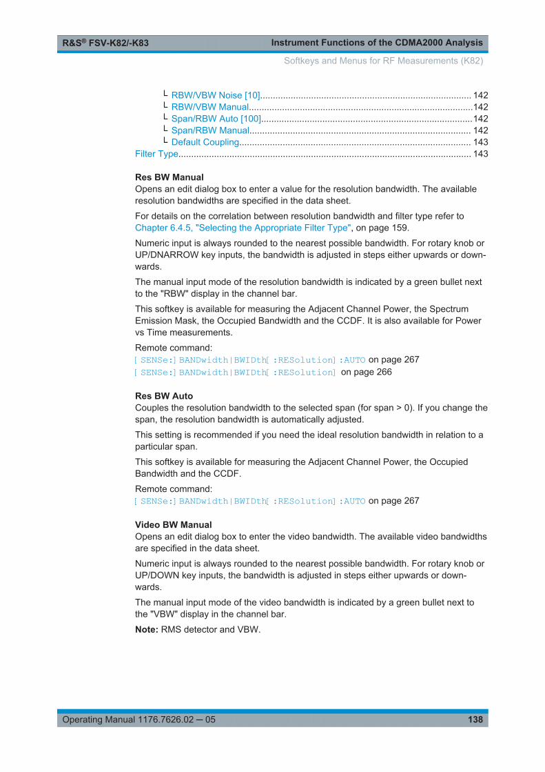
Instrument Functions of the CDMA2000 AnalysisR&S® FSV-K82/-K83
138Operating Manual 1176.7626.02 ─ 05
└ RBW/VBW Noise [10]................................................................................... 142└ RBW/VBW Manual........................................................................................142└ Span/RBW Auto [100]...................................................................................142└ Span/RBW Manual....................................................................................... 142└ Default Coupling........................................................................................... 143
Filter Type................................................................................................................... 143
Res BW ManualOpens an edit dialog box to enter a value for the resolution bandwidth. The availableresolution bandwidths are specified in the data sheet.
For details on the correlation between resolution bandwidth and filter type refer toChapter 6.4.5, "Selecting the Appropriate Filter Type", on page 159.
Numeric input is always rounded to the nearest possible bandwidth. For rotary knob orUP/DNARROW key inputs, the bandwidth is adjusted in steps either upwards or down-wards.
The manual input mode of the resolution bandwidth is indicated by a green bullet nextto the "RBW" display in the channel bar.
This softkey is available for measuring the Adjacent Channel Power, the SpectrumEmission Mask, the Occupied Bandwidth and the CCDF. It is also available for Powervs Time measurements.
Remote command: [SENSe:]BANDwidth|BWIDth[:RESolution]:AUTO on page 267[SENSe:]BANDwidth|BWIDth[:RESolution] on page 266
Res BW AutoCouples the resolution bandwidth to the selected span (for span > 0). If you change thespan, the resolution bandwidth is automatically adjusted.
This setting is recommended if you need the ideal resolution bandwidth in relation to aparticular span.
This softkey is available for measuring the Adjacent Channel Power, the OccupiedBandwidth and the CCDF.
Remote command: [SENSe:]BANDwidth|BWIDth[:RESolution]:AUTO on page 267
Video BW ManualOpens an edit dialog box to enter the video bandwidth. The available video bandwidthsare specified in the data sheet.
Numeric input is always rounded to the nearest possible bandwidth. For rotary knob orUP/DOWN key inputs, the bandwidth is adjusted in steps either upwards or down-wards.
The manual input mode of the video bandwidth is indicated by a green bullet next tothe "VBW" display in the channel bar.
Note: RMS detector and VBW.
Softkeys and Menus for RF Measurements (K82)

Instrument Functions of the CDMA2000 AnalysisR&S® FSV-K82/-K83
139Operating Manual 1176.7626.02 ─ 05
If an RMS detector is used, the video bandwidth in the hardware is bypassed. Thus,duplicate trace averaging with small VBWs and RMS detector no longer occurs. How-ever, the VBW is still considered when calculating the sweep time. This leads to a lon-ger sweep time for small VBW values. Thus, you can reduce the VBW value to achievemore stable trace curves even when using an RMS detector. Normally, if the RMSdetector is used the sweep time should be increased to get more stable trace curves.For details on detectors see Chapter 6.4.3, "Detector Overview", on page 156.This softkey is available for measuring the Adjacent Channel Power, the SpectrumEmission Mask and the Occupied Bandwidth.
Remote command: [SENSe:]BANDwidth|BWIDth:VIDeo:AUTO on page 269[SENSe:]BANDwidth|BWIDth:VIDeo on page 268
Video BW AutoCouples the video bandwidth to the resolution bandwidth. If you change the resolutionbandwidth, the video bandwidth is automatically adjusted.
This setting is recommended if a minimum sweep time is required for a selected reso-lution bandwidth. Narrow video bandwidths result in longer sweep times due to the lon-ger settling time. Wide bandwidths reduce the signal/noise ratio.
This softkey is available for measuring the Adjacent Channel Power, the SpectrumEmission Mask and the Occupied Bandwidth.
Remote command: [SENSe:]BANDwidth|BWIDth:VIDeo:AUTO on page 269
Sweeptime ManualOpens an edit dialog box to enter the sweep time.
Sweep time
absolute max. sweep time value: 16000 s
absolute min. sweep time value: zero span: 1 μs
span > 0: depends on device model (refer to data sheet)
Allowed values depend on the ratio of span to RBW and RBW to VBW. For detailsrefer to the data sheet.
Numeric input is always rounded to the nearest possible sweep time. For rotary knobor UPARROW/DNARROW key inputs, the sweep time is adjusted in steps eitherdownwards or upwards.
The manual input mode of the sweep time is indicated by a green bullet next to the"SWT" display in the channel bar. If the selected sweep time is too short for theselected bandwidth and span, level measurement errors will occur due to a too shortsettling time for the resolution or video filters. In this case, the R&S FSV/FSVA displaysthe error message "UNCAL" and marks the indicated sweep time with a red bullet.
This softkey is available for RF measurements, but not for CCDF measurements.
Softkeys and Menus for RF Measurements (K82)

Instrument Functions of the CDMA2000 AnalysisR&S® FSV-K82/-K83
140Operating Manual 1176.7626.02 ─ 05
Remote command: SWE:TIME:AUTO OFF, see [SENSe:]SWEep:TIME:AUTO on page 288[SENSe:]SWEep:TIME on page 288
Sweeptime AutoCouples the sweep time to the span, video bandwidth (VBW) and resolution bandwidth(RBW) (not available for zero span). If you change the span, resolution bandwidth orvideo bandwidth, the sweep time is automatically adjusted.
The R&S FSV/FSVA always selects the shortest sweep time that is possible withoutfalsifying the signal. The maximum level error is < 0.1 dB, compared to using a longersweep time.
This softkey is available for measuring the Adjacent Channel Power, the SpectrumEmission Mask and the Occupied Bandwidth.
Remote command: [SENSe:]SWEep:TIME:AUTO on page 288
Sweep TypeOpens a submenu to define the sweep type.
This softkey is available for measuring the Signal Power, the Adjacent Channel Powerand the Occupied Bandwidth.
This function is not available in IQ Analyzer mode or for input from the R&S Digital I/QInterface (option R&S FSV-B17).
In frequency sweep mode, the analyzer provides several possible methods of sweep-ing:● "Sweep" on page 140● "FFT" on page 140 (not available with 5-Pole filters, channel filters or RRC filters,
see Chapter 6.4.5, "Selecting the Appropriate Filter Type", on page 159)● "Auto" on page 141
Sweep ← Sweep TypeSets the Sweep Type to standard analog frequency sweep.
In the standard sweep mode, the local oscillator is set to provide the spectrum quasianalog from the start to the stop frequency.
Remote command: SWE:TYPE SWE, see [SENSe:]SWEep:TYPE on page 289
FFT ← Sweep TypeSets the Sweep Type to FFT mode.
The FFT sweep mode samples on a defined frequency value and transforms it to thespectrum by fast Fourier transformation (FFT).
FFT is not available when using 5-Pole filters, Channel filters or RRC filters. In thiscase, sweep mode is used.
Note: The same applies when a tracking generator (internal or external, optionsR&S FSV-B9/B10) is active.
Softkeys and Menus for RF Measurements (K82)
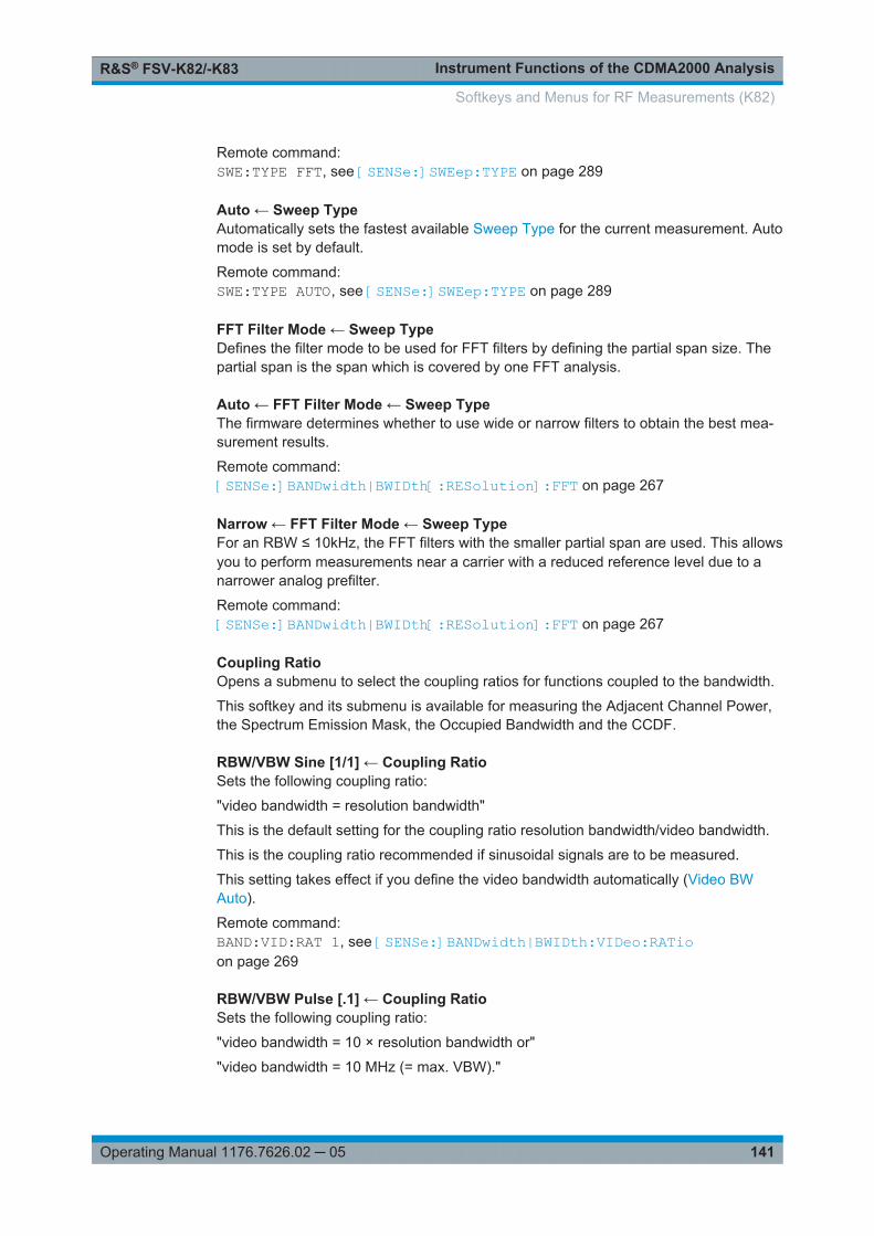
Instrument Functions of the CDMA2000 AnalysisR&S® FSV-K82/-K83
141Operating Manual 1176.7626.02 ─ 05
Remote command: SWE:TYPE FFT, see [SENSe:]SWEep:TYPE on page 289
Auto ← Sweep TypeAutomatically sets the fastest available Sweep Type for the current measurement. Automode is set by default.
Remote command: SWE:TYPE AUTO, see [SENSe:]SWEep:TYPE on page 289
FFT Filter Mode ← Sweep TypeDefines the filter mode to be used for FFT filters by defining the partial span size. Thepartial span is the span which is covered by one FFT analysis.
Auto ← FFT Filter Mode ← Sweep TypeThe firmware determines whether to use wide or narrow filters to obtain the best mea-surement results.
Remote command: [SENSe:]BANDwidth|BWIDth[:RESolution]:FFT on page 267
Narrow ← FFT Filter Mode ← Sweep TypeFor an RBW ≤ 10kHz, the FFT filters with the smaller partial span are used. This allowsyou to perform measurements near a carrier with a reduced reference level due to anarrower analog prefilter.
Remote command: [SENSe:]BANDwidth|BWIDth[:RESolution]:FFT on page 267
Coupling RatioOpens a submenu to select the coupling ratios for functions coupled to the bandwidth.
This softkey and its submenu is available for measuring the Adjacent Channel Power,the Spectrum Emission Mask, the Occupied Bandwidth and the CCDF.
RBW/VBW Sine [1/1] ← Coupling RatioSets the following coupling ratio:
"video bandwidth = resolution bandwidth"
This is the default setting for the coupling ratio resolution bandwidth/video bandwidth.
This is the coupling ratio recommended if sinusoidal signals are to be measured.
This setting takes effect if you define the video bandwidth automatically (Video BWAuto).
Remote command: BAND:VID:RAT 1, see [SENSe:]BANDwidth|BWIDth:VIDeo:RATioon page 269
RBW/VBW Pulse [.1] ← Coupling RatioSets the following coupling ratio:
"video bandwidth = 10 × resolution bandwidth or"
"video bandwidth = 10 MHz (= max. VBW)."
Softkeys and Menus for RF Measurements (K82)

Instrument Functions of the CDMA2000 AnalysisR&S® FSV-K82/-K83
142Operating Manual 1176.7626.02 ─ 05
This coupling ratio is recommended whenever the amplitudes of pulsed signals are tobe measured correctly. The IF filter is exclusively responsible for pulse shaping. Noadditional evaluation is performed by the video filter.
This setting takes effect if you define the video bandwidth automatically (Video BWAuto).
Remote command: BAND:VID:RAT 10, see [SENSe:]BANDwidth|BWIDth:VIDeo:RATioon page 269
RBW/VBW Noise [10] ← Coupling RatioSets the following coupling ratio:
"video bandwidth = resolution bandwidth/10"
At this coupling ratio, noise and pulsed signals are suppressed in the video domain.For noise signals, the average value is displayed.
This setting takes effect if you define the video bandwidth automatically (Video BWAuto).
Remote command: BAND:VID:RAT 0.1, see [SENSe:]BANDwidth|BWIDth:VIDeo:RATioon page 269
RBW/VBW Manual ← Coupling RatioActivates the manual input of the coupling ratio.
The resolution bandwidth/video bandwidth ratio can be set in the range 0.001 to 1000.
This setting takes effect if you define the video bandwidth automatically (Video BWAuto).
Remote command: BAND:VID:RAT 10, see [SENSe:]BANDwidth|BWIDth:VIDeo:RATioon page 269
Span/RBW Auto [100] ← Coupling RatioSets the following coupling ratio:
"resolution bandwidth = span/100"
This coupling ratio is the default setting of the R&S FSV/FSVA.
This setting takes effect if you define the resolution bandwidth automatically (Res BWAuto).
Remote command: BAND:VID:RAT 0.001, see [SENSe:]BANDwidth|BWIDth:VIDeo:RATioon page 269
Span/RBW Manual ← Coupling RatioActivates the manual input of the coupling ratio.
This setting takes effect if you define the resolution bandwidth automatically (Res BWAuto).
The span/resolution bandwidth ratio can be set in the range 1 to 10000.
Softkeys and Menus for RF Measurements (K82)

Instrument Functions of the CDMA2000 AnalysisR&S® FSV-K82/-K83
143Operating Manual 1176.7626.02 ─ 05
Remote command: BAND:RAT 0.1, see [SENSe:]BANDwidth|BWIDth[:RESolution]:RATioon page 268
Default Coupling ← Coupling RatioSets all coupled functions to the default state ("AUTO").
In addition, the ratio "RBW/VBW" is set to "SINE [1/1]" and the ratio "SPAN/RBW" to100.
Remote command: [SENSe:]BANDwidth|BWIDth[:RESolution]:AUTO on page 267[SENSe:]BANDwidth|BWIDth:VIDeo:AUTO on page 269[SENSe:]SWEep:TIME:AUTO on page 288
Filter TypeOpens a submenu to select the filter type.
This softkey and its submenu are available for measuring the Adjacent Channel Power,the Spectrum Emission Mask, the Occupied Bandwidth and the CCDF. Instead ofopening a submenu, this softkey opens the "Sweep List" dialog box to select the filtertype when measuring the Spectrum Emission Mask.
The submenu contains the following softkeys:● Normal (3 dB)● CISPR (6 dB)● MIL Std (6 dB)
Note that the 6 dB bandwidths are available only with option R&S FSV-K54.● Channel● RRC● 5-Pole (not available for sweep type "FFT")For detailed information on filters see Chapter 6.4.5, "Selecting the Appropriate FilterType", on page 159 and Chapter 6.4.6, "List of Available RRC and Channel Filters",on page 160.
Remote command: [SENSe:]BANDwidth|BWIDth[:RESolution]:TYPE on page 268
6.3.6 Softkeys of the Sweep Menu
The following table shows all softkeys available in the "Sweep" menu. It is possible thatyour instrument configuration does not provide all softkeys. If a softkey is only availablewith a special option, model or (measurement) mode, this information is provided in thecorresponding softkey description.
Continuous Sweep...................................................................................................... 144Single Sweep.............................................................................................................. 144Continue Single Sweep...............................................................................................144Sweeptime Manual......................................................................................................144Sweeptime Auto.......................................................................................................... 145Sweep Type................................................................................................................ 145
└ Sweep...........................................................................................................145
Softkeys and Menus for RF Measurements (K82)

Instrument Functions of the CDMA2000 AnalysisR&S® FSV-K82/-K83
144Operating Manual 1176.7626.02 ─ 05
└ FFT............................................................................................................... 145└ Auto...............................................................................................................146└ FFT Filter Mode............................................................................................ 146
└ Auto.................................................................................................... 146└ Narrow................................................................................................ 146
Sweep Count...............................................................................................................146Sweep Points.............................................................................................................. 146
Continuous SweepSets the continuous sweep mode: the sweep takes place continuously according to thetrigger settings. This is the default setting.
The trace averaging is determined by the sweep count value (see the "Sweep Count"softkey, "Sweep Count" on page 85).
Remote command: INIT:CONT ON, see INITiate<n>:CONTinuous on page 312
Single SweepSets the single sweep mode: after triggering, starts the number of sweeps that aredefined by using the Sweep Count softkey. The measurement stops after the definednumber of sweeps has been performed.
Remote command: INIT:CONT OFF, see INITiate<n>:CONTinuous on page 312
Continue Single SweepRepeats the number of sweeps set by using the Sweep Count softkey, without deletingthe trace of the last measurement.
This is particularly of interest when using the trace configurations "Average" or "MaxHold" to take previously recorded measurements into account for averaging/maximumsearch.
Remote command: INITiate<n>:CONMeas on page 311
Sweeptime ManualOpens an edit dialog box to enter the sweep time.
Sweep time
absolute max. sweep time value: 16000 s
absolute min. sweep time value: zero span: 1 μs
span > 0: depends on device model (refer to data sheet)
Allowed values depend on the ratio of span to RBW and RBW to VBW. For detailsrefer to the data sheet.
Numeric input is always rounded to the nearest possible sweep time. For rotary knobor UPARROW/DNARROW key inputs, the sweep time is adjusted in steps eitherdownwards or upwards.
Softkeys and Menus for RF Measurements (K82)

Instrument Functions of the CDMA2000 AnalysisR&S® FSV-K82/-K83
145Operating Manual 1176.7626.02 ─ 05
The manual input mode of the sweep time is indicated by a green bullet next to the"SWT" display in the channel bar. If the selected sweep time is too short for theselected bandwidth and span, level measurement errors will occur due to a too shortsettling time for the resolution or video filters. In this case, the R&S FSV/FSVA displaysthe error message "UNCAL" and marks the indicated sweep time with a red bullet.
This softkey is available for RF measurements, but not for CCDF measurements.
Remote command: SWE:TIME:AUTO OFF, see [SENSe:]SWEep:TIME:AUTO on page 288[SENSe:]SWEep:TIME on page 288
Sweeptime AutoCouples the sweep time to the span, video bandwidth (VBW) and resolution bandwidth(RBW) (not available for zero span). If you change the span, resolution bandwidth orvideo bandwidth, the sweep time is automatically adjusted.
The R&S FSV/FSVA always selects the shortest sweep time that is possible withoutfalsifying the signal. The maximum level error is < 0.1 dB, compared to using a longersweep time.
This softkey is available for measuring the Adjacent Channel Power, the SpectrumEmission Mask and the Occupied Bandwidth.
Remote command: [SENSe:]SWEep:TIME:AUTO on page 288
Sweep TypeOpens a submenu to define the sweep type.
This softkey is available for measuring the Signal Power, the Adjacent Channel Powerand the Occupied Bandwidth.
This function is not available in IQ Analyzer mode or for input from the R&S Digital I/QInterface (option R&S FSV-B17).
In frequency sweep mode, the analyzer provides several possible methods of sweep-ing:● "Sweep" on page 140● "FFT" on page 140 (not available with 5-Pole filters, channel filters or RRC filters,
see Chapter 6.4.5, "Selecting the Appropriate Filter Type", on page 159)● "Auto" on page 141
Sweep ← Sweep TypeSets the Sweep Type to standard analog frequency sweep.
In the standard sweep mode, the local oscillator is set to provide the spectrum quasianalog from the start to the stop frequency.
Remote command: SWE:TYPE SWE, see [SENSe:]SWEep:TYPE on page 289
FFT ← Sweep TypeSets the Sweep Type to FFT mode.
The FFT sweep mode samples on a defined frequency value and transforms it to thespectrum by fast Fourier transformation (FFT).
Softkeys and Menus for RF Measurements (K82)

Instrument Functions of the CDMA2000 AnalysisR&S® FSV-K82/-K83
146Operating Manual 1176.7626.02 ─ 05
FFT is not available when using 5-Pole filters, Channel filters or RRC filters. In thiscase, sweep mode is used.
Note: The same applies when a tracking generator (internal or external, optionsR&S FSV-B9/B10) is active.
Remote command: SWE:TYPE FFT, see [SENSe:]SWEep:TYPE on page 289
Auto ← Sweep TypeAutomatically sets the fastest available Sweep Type for the current measurement. Automode is set by default.
Remote command: SWE:TYPE AUTO, see [SENSe:]SWEep:TYPE on page 289
FFT Filter Mode ← Sweep TypeDefines the filter mode to be used for FFT filters by defining the partial span size. Thepartial span is the span which is covered by one FFT analysis.
Auto ← FFT Filter Mode ← Sweep TypeThe firmware determines whether to use wide or narrow filters to obtain the best mea-surement results.
Remote command: [SENSe:]BANDwidth|BWIDth[:RESolution]:FFT on page 267
Narrow ← FFT Filter Mode ← Sweep TypeFor an RBW ≤ 10kHz, the FFT filters with the smaller partial span are used. This allowsyou to perform measurements near a carrier with a reduced reference level due to anarrower analog prefilter.
Remote command: [SENSe:]BANDwidth|BWIDth[:RESolution]:FFT on page 267
Sweep CountOpens an edit dialog box to enter the number of sweeps to be performed in the singlesweep mode. Values from 0 to 32767 are allowed. If the values 0 or 1 are set, onesweep is performed. The sweep count is applied to all the traces in a diagram.
If the trace configurations "Average", "Max Hold" or "Min Hold" are set, the sweepcount value also determines the number of averaging or maximum search procedures.
In continuous sweep mode, if sweep count = 0 (default), averaging is performed over10 sweeps. For sweep count =1, no averaging, maxhold or minhold operations are per-formed.
Remote command: [SENSe:]SWEep:COUNt on page 284
Sweep PointsOpens an edit dialog box to enter the number of measured values to be collected dur-ing one sweep.● Entry via rotary knob:
Softkeys and Menus for RF Measurements (K82)

Instrument Functions of the CDMA2000 AnalysisR&S® FSV-K82/-K83
147Operating Manual 1176.7626.02 ─ 05
– In the range from 101 to 1001, the sweep points are increased or decreased insteps of 100 points.
– In the range from 1001 to 32001, the sweep points are increased or decreasedin steps of 1000 points.
● Entry via keypad:All values in the defined range can be set.
The default value is 691 sweep points.
This softkey is available for RF measurements.
Remote command: [SENSe:]SWEep:POINts on page 288
6.3.7 Softkeys of the Marker Menu for RF Measurements
The following chapter describes all softkeys available in the ""Marker"" menu in""CDMA2000 BTS Analysis"" Mode for RF measurements. For CDA measurements,see Chapter 6.2.7, "Softkeys of the Marker Menu for CDA Measurements",on page 88.
Marker 1 / Marker 2 / Marker 3 / … Marker 16,/ Marker Norm/Delta.......................... 147More Markers.............................................................................................................. 148Marker Norm/Delta......................................................................................................148Marker to Trace...........................................................................................................148All Marker Off.............................................................................................................. 148Marker Table............................................................................................................... 148Marker Stepsize.......................................................................................................... 148
└ Stepsize Standard.........................................................................................149└ Stepsize Sweep Points................................................................................. 149
Link Mkr1 and Delta1.................................................................................................. 149
Marker 1 / Marker 2 / Marker 3 / … Marker 16,/ Marker Norm/DeltaThe "Marker X" softkey activates the corresponding marker and opens an edit dialogbox to enter a value for the marker to be set to. Pressing the softkey again deactivatesthe selected marker.
If a marker value is changed using the rotary knob, the step size is defined via theStepsize Standard or Stepsize Sweep Points softkeys.
Marker 1 is always the reference marker for relative measurements. If activated, mark-ers 2 to 16 are delta markers that refer to marker 1. These markers can be convertedinto markers with absolute value display using the "Marker Norm/Delta" softkey. Ifmarker 1 is the active marker, pressing the "Marker Norm/Delta" softkey switches onan additional delta marker.
Remote command: CALCulate<n>:MARKer<m>[:STATe] on page 214CALCulate<n>:MARKer<m>:X on page 215CALCulate<n>:MARKer<m>:Y? on page 217CALCulate<n>:DELTamarker<m>[:STATe] on page 197CALCulate<n>:DELTamarker<m>:X on page 198
Softkeys and Menus for RF Measurements (K82)

Instrument Functions of the CDMA2000 AnalysisR&S® FSV-K82/-K83
148Operating Manual 1176.7626.02 ─ 05
CALCulate<n>:DELTamarker<m>:X:RELative? on page 198CALCulate<n>:DELTamarker<m>:Y? on page 198
More MarkersOpens a sub-menu to select one of up to 16 available markers. See "Marker 1 / Marker2 / Marker 3 / … Marker 16,/ Marker Norm/Delta" on page 147.
Marker Norm/DeltaChanges the active marker to a normal (norm) or delta marker (with respect to marker1).
Remote command: CALCulate<n>:MARKer<m>[:STATe] on page 214CALCulate<n>:DELTamarker<m>[:STATe] on page 197
Marker to TraceOpens an edit dialog box to enter the number of the trace on which the marker is to beplaced.
Remote command: CALCulate<n>:MARKer<m>:TRACe on page 215
All Marker OffSwitches all markers off. It also switches off all functions and displays that are associ-ated with the markers/delta markers.
Remote command: CALCulate<n>:MARKer<m>:AOFF on page 211
Marker TableDefines how the marker information is displayed.
This softkey is available for RF measurements.
For more information, see "Displayed Marker Information" in the description of thebase unit.
"On" Displays the marker information in a table in a separate area beneaththe diagram.
"Off" Displays the marker information within the diagram area.
"Aut" (Default) The marker table is displayed automatically if more than 2markers are active, and removed if only 1 or 2 markers are active.This helps keep the information in the display clear.
Remote command: DISPlay:MTABle on page 235
Marker StepsizeOpens a submenu to set the step size of all markers and delta markers.
Default value for the marker step size is Stepsize Sweep Points.
This softkey is available for RF measurements.
Softkeys and Menus for RF Measurements (K82)

Instrument Functions of the CDMA2000 AnalysisR&S® FSV-K82/-K83
149Operating Manual 1176.7626.02 ─ 05
Stepsize Standard ← Marker StepsizeMoves the marker or delta marker from one measurement point to the next, if themarker or delta marker value is changed via the rotary knob ( "Marker 1 / Marker 2 /Marker 3 / … Marker 16,/ Marker Norm/Delta" softkeys, see "Marker 1 / Marker 2 /Marker 3 / … Marker 16,/ Marker Norm/Delta" on page 147). If more measured valuesthan measurement points exist, it is not possible to read out all measured values. Inthis case, use the Stepsize Sweep Points softkey.
Remote command: CALC:MARK:X:SSIZ STAN (see CALCulate<n>:MARKer<m>:X:SSIZeon page 216)
Stepsize Sweep Points ← Marker StepsizeMoves the marker or delta marker from one measured value to the next, if the markeror delta marker value is changed via the rotary knob ( "Marker 1 / Marker 2 / Marker 3 /… Marker 16,/ Marker Norm/Delta" softkeys, see "Marker 1 / Marker 2 / Marker 3 / …Marker 16,/ Marker Norm/Delta" on page 147). If more measured values than mea-surement points exist, every single measured value is accessible and its value is dis-played in the marker field.
The number of measured values is defined in the ""Sweep"" menu via the SweepPoints softkey.
This functionality is available for all base unit measurements with the exception of sta-tistics ( "APD" and "CCDF" softkeys in the "Measurement" menu).
Remote command: CALC:MARK:X:SSIZ POIN (see CALCulate<n>:MARKer<m>:X:SSIZeon page 216)
Link Mkr1 and Delta1The delta marker 1 is linked to marker 1, so if the x-axis value of the marker 1 ischanged, the delta marker 1 will follow on the same x-position. The link is off bydefault.
You can set the two markers on different traces to measure the difference (e.g.between a max hold trace and a min hold trace or between a measurement and a ref-erence trace).
This softkey is available for RF measurements.
Remote command: CALCulate<n>:DELTamarker<m>:LINK on page 194
6.3.8 Softkeys of the Input/Output Menu for RF Measurements
The following chapter describes all softkeys available in the "Input/Output" menu forRF measurements. For CDA measurements, see Chapter 6.2.10, "Softkeys of theInput/Output Menu for CDA Measurements", on page 93.
Softkeys and Menus for RF Measurements (K82)

Instrument Functions of the CDMA2000 AnalysisR&S® FSV-K82/-K83
150Operating Manual 1176.7626.02 ─ 05
Input (AC/DC)..............................................................................................................150Noise Source...............................................................................................................150Video Output............................................................................................................... 150Power Sensor..............................................................................................................150Trigger Out.................................................................................................................. 150
Input (AC/DC)Toggles the RF input of the R&S FSV/FSVA between AC and DC coupling.
This function is not available for input from the R&S Digital I/Q Interface (optionR&S FSV-B17).
Remote command: INPut:COUPling on page 301
Noise SourceSwitches the supply voltage for an external noise source on or off. For details on con-nectors refer to the R&S FSV/FSVA Quick Start Guide, "Front and Rear Panel" chap-ter.
Remote command: DIAGnostic<n>:SERVice:NSOurce on page 310
Video OutputSends a video output signal according to the measured level to the connector on therear panel of the R&S FSV/FSVA.
Note: Video output does not return valid values in IQ or FFT mode.
Remote command: OUTP:IF VID , see OUTPut:IF[:SOURce] on page 314
Power SensorFor precise power measurement a power sensor can be connected to the instrumentvia the front panel (USB connector) or the rear panel (power sensor, option R&S FSV-B5). The Power Sensor Support firmware option (R&S FSV-K9) provides the powermeasurement functions for this test setup.
This softkey is only available if the R&S FSV/FSVA option Power Sensor (R&S FSV-K9) is installed.
For details see the chapter "Instrument Functions Power Sensor (K9)" in the base unitdescription.
This softkey is available for RF measurements.
Trigger OutSets the Trigger Out port in the Additional Interfaces (option R&S FSV-B5 only) to lowor high. Thus, you can trigger an additional device via the external trigger port, forexample.
This softkey is available for RF measurements.
Softkeys and Menus for RF Measurements (K82)

Instrument Functions of the CDMA2000 AnalysisR&S® FSV-K82/-K83
151Operating Manual 1176.7626.02 ─ 05
Remote command: OUTPut:TRIGger on page 314
6.4 Further Information
6.4.1 Predefined Channel Tables.........................................................................................151
6.4.1.1 Relationship Between Channel and Modulation Type................................................ 154
6.4.2 Working with Channel Tables..................................................................................... 155
6.4.3 Detector Overview.......................................................................................................156
6.4.4 Trace Mode Overview................................................................................................. 157
6.4.5 Selecting the Appropriate Filter Type..........................................................................159
6.4.6 List of Available RRC and Channel Filters.................................................................. 160
6.4.7 ASCII File Export Format............................................................................................ 161
6.4.8 ASCII File Export Format (Spectrum Emission Mask)................................................ 162
6.4.9 Format Description of Spectrum Emission Mask XML Files....................................... 163
6.4.10 Provided XML Files for the Spectrum Emission Mask Measurement......................... 168
6.4.11 Ranges and Range Settings....................................................................................... 171
6.4.12 Fast Spectrum Emission Mask Measurements...........................................................172
6.4.13 Predefined CP/ACLR Standards.................................................................................174
6.4.14 Optimized Settings for CP/ACLR Test Parameters.....................................................175
6.4.1 Predefined Channel Tables
Predefined channel tables offer access to a quick configuration for the channel search.The CDMA2000 BTS Analysis (R&S FSV-K82) option provides the following set ofchannel tables compliant with the CDMA2000 specification:
Channel table Contents
RECENT Contains the channels that were automatically cre-ated during the last measurement with the "AutoSearch" option activated (for details refer to "Chan-nel Tables" on page 67).
MPC_RC1 (Base Station Main Path 6 ChannelsRadio Configuration 1)
Channel table with F-PICH/F-SYNC/F-PCH and 6data channels.
MPC_RC4 (Base Station Main Path 6 ChannelsRadio Configuration 4)
Channel table with F-PICH/F-SYNC/F-PCH and 6data channels.
Further Information

Instrument Functions of the CDMA2000 AnalysisR&S® FSV-K82/-K83
152Operating Manual 1176.7626.02 ─ 05
Channel table Contents
TDC_RC4 (Base Station Transmit Diversity Path 6Channels Radio Configuration 4)
Channel table with F-PICH/F-SYNC/F-PCH and 6data channels.
BPC_RC4 (Base Station Both Paths 6 ChannelsRadio Configuration 4)
Channel table with F-PICH/F-TDPICH/F-SYNC/F-PCH and 6 data channels
This standard does not specify a channel numberfor the data channels.
The CDMA2000 MS Analysis (R&S FSV-K83) option provides the following set ofchannel tables compliant with the CDMA2000 specification:
Channel table Contents
RECENT Contains the channels that were automatically created during the last mea-surement with the "Auto Search" option activated (for details refer to "ChannelTables" on page 67).
EACHOP Channel table for Enhanced Access CHannel OPeration with PICH and EACH
RCCCHOP Channel table for Reverse Common Control CHannel OPeration with PICHand CCCH
RTCHOP3 Channel table for Reverse Traffic CHannel OPeration with the following 3channels: PICH/DCCH/FCH
RTCHOP5 Channel table for Reverse Traffic CHannel OPeration with the following 5channels: PICH/DCCH/FCH/S1CH/S2CH
To use channels other than those in the predefined channel tables, you can copy theoriginal tables and modify the channels in the copy.
Table 6-1: Base station channel table for main branch in radio configuration 1 (MPC_RC1)
Channel Type Number of Chan-nels
Code Channel (WalshCode.SF)
Radio Configura-tion
F-PICH 1 0.64 -
F-SYNC 1 32.64 -
F-PCH 1 1.64 -
CHAN 6 9.64
10.64
11.64
15.64
17.64
25.64
1
1
1
1
1
1
Further Information

Instrument Functions of the CDMA2000 AnalysisR&S® FSV-K82/-K83
153Operating Manual 1176.7626.02 ─ 05
Table 6-2: Base station channel table for main branch in radio configuration 4 (MPC_RC4)
Channel Type Number of Chan-nels
Code Channel (WalshCode.SF)
Radio Configura-tion
F-PICH 1 0.64 -
F-SYNC 1 32.64 -
F-PCH 1 1.64 -
CHAN 6 9.128
10.128
11.128
15.128
17.128
25.128
4
4
4
4
4
4
Table 6-3: Base station test model for aggregate signal in radio configuration 4 (TDC_RC4)
Channel Type Number of Chan-nels
Code Channel (WalshCode.SF)
Radio Configura-tion
F-PICH 1 16.128 -
F-SYNC 1 32.64 -
F-PCH 1 1.64 -
CHAN 6 9.128
10.128
11.128
15.128
17.128
25.128
4
4
4
4
4
4
Table 6-4: Base station test model for aggregate signal in radio configuration 4 (BPC_RC4)
Channel Type Number of Chan-nels
Code Channel (WalshCode.SF)
Radio Configura-tion
F-PICH 1 0.64 -
F-SYNC 1 16.128 -
1 32.64 -
F-PCH 1 1.64 -
CHAN 6 9.128
10.128
11.128
15.128
17.128
25.128
4
4
4
4
4
4
Further Information

Instrument Functions of the CDMA2000 AnalysisR&S® FSV-K82/-K83
154Operating Manual 1176.7626.02 ─ 05
Table 6-5: Channel table for enhanced access channel operation
Channel type Code channel (Walsh Code.SF) Mapping
PICH 0.32 I
EACH 2.8 Q
Table 6-6: Channel table for reverse commom control channel operation
Channel type Code channel (Walsh Code.SF) Mapping
PICH 0.32 I
CCCH 2.8 Q
Table 6-7: Channel table for REVERSE TRAFFIC CHANNEL OPERATION 3
Channel type Code channel (Walsh Code.SF) Mapping
PICH 0.32 I
FCH 4.16 Q
S1CH 2.4 Q
Table 6-8: Channel table for REVERSE TRAFFIC CHANNEL OPERATION 5
Channel type Code channel (Walsh Code.SF) Mapping
PICH 0.32 I
DCCH 8.16 I
FCH 4.16 Q
S1CH 2.4 Q
S2CH 6.8 I
6.4.1.1 Relationship Between Channel and Modulation Type
Channel type Channel Modulation
F-PICH Pilot channel BPSK
F-SYNC Synchronisation channel BPSK
F-PCH Paging channel BPSK
F-TDPICH Transmit diversity pilot channel BPSK
F-APICH Auxiliary pilot channel BPSK
F-ATDPICH Auxiliary transmit diversity channel BPSK
F-BCH Broadcast channel QPSK
F-CPCCH Common power control channel QPSK
F-CACH Common assignment channel QPSK
F-CCCH Common control channel QPSK
Further Information

Instrument Functions of the CDMA2000 AnalysisR&S® FSV-K82/-K83
155Operating Manual 1176.7626.02 ─ 05
F-PDCCH Packet data control channel QPSK
F-PDCH Packet data channel QPSK, 8PSK or 16QAM
CHAN Data channel radio configuration 1-2 BPSK
CHAN Data channel radio configuration 3-5 QPSK
6.4.2 Working with Channel Tables
Creating a channel table
1. Select the "Code Domain Analyzer" softkey.
2. Select the "Channel Table Settings" softkey.The "Channel Table Settings" dialog box is displayed.
3. Select the "Predef" channel search mode and set a threshold for inactive channels.
4. Press the "New / Copy / Edit" on page 67 softkey to create a new channel table.The "New Channel Table" dialog box is displayed. The new channel table containsno data at all.
5. Enter a name for the new channel table, e.g. 'Test Table' in the corresponding field.The name you enter in this field is also the name of the table channel file.
6. Enter a description for your new channel table, e.g. 'Channel table created for testpurposes' in the "Description" field.
7. Build your channel table by adding the channels with the configuration you needorMeasure the current signal by pressing the "Meas" on page 69 softkey. TheR&S FSV/FSVA automatically adds the channels of the current signal to the chan-nel table.Refer to the "New / Copy / Edit" on page 67 softkey for a description of all parame-ters relating to a channel.
8. Save your table by pressing the "Save" on page 69 softkey. All data is lost if youjust close the dialog box.The list of available channel tables in the "Channel Table Settings" dialog box nowcontains the 'Test Table'.
Editing a channel table
1. Select the "Code Domain Analyzer" softkey.
2. Select the "Channel Table Settings" softkey.
3. Select your recently created channel table. Press the "New / Copy / Edit"on page 67 softkey to open and modify the channel table.Each row in the channel table represents one channel.
Further Information
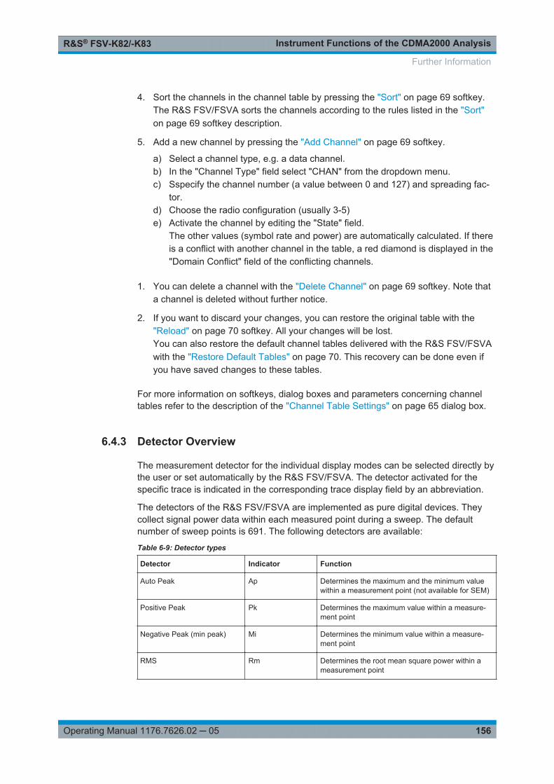
Instrument Functions of the CDMA2000 AnalysisR&S® FSV-K82/-K83
156Operating Manual 1176.7626.02 ─ 05
4. Sort the channels in the channel table by pressing the "Sort" on page 69 softkey.The R&S FSV/FSVA sorts the channels according to the rules listed in the "Sort"on page 69 softkey description.
5. Add a new channel by pressing the "Add Channel" on page 69 softkey.
a) Select a channel type, e.g. a data channel.b) In the "Channel Type" field select "CHAN" from the dropdown menu.c) Sspecify the channel number (a value between 0 and 127) and spreading fac-
tor.d) Choose the radio configuration (usually 3-5)e) Activate the channel by editing the "State" field.
The other values (symbol rate and power) are automatically calculated. If thereis a conflict with another channel in the table, a red diamond is displayed in the"Domain Conflict" field of the conflicting channels.
1. You can delete a channel with the "Delete Channel" on page 69 softkey. Note thata channel is deleted without further notice.
2. If you want to discard your changes, you can restore the original table with the"Reload" on page 70 softkey. All your changes will be lost.You can also restore the default channel tables delivered with the R&S FSV/FSVAwith the "Restore Default Tables" on page 70. This recovery can be done even ifyou have saved changes to these tables.
For more information on softkeys, dialog boxes and parameters concerning channeltables refer to the description of the "Channel Table Settings" on page 65 dialog box.
6.4.3 Detector Overview
The measurement detector for the individual display modes can be selected directly bythe user or set automatically by the R&S FSV/FSVA. The detector activated for thespecific trace is indicated in the corresponding trace display field by an abbreviation.
The detectors of the R&S FSV/FSVA are implemented as pure digital devices. Theycollect signal power data within each measured point during a sweep. The defaultnumber of sweep points is 691. The following detectors are available:
Table 6-9: Detector types
Detector Indicator Function
Auto Peak Ap Determines the maximum and the minimum valuewithin a measurement point (not available for SEM)
Positive Peak Pk Determines the maximum value within a measure-ment point
Negative Peak (min peak) Mi Determines the minimum value within a measure-ment point
RMS Rm Determines the root mean square power within ameasurement point
Further Information

Instrument Functions of the CDMA2000 AnalysisR&S® FSV-K82/-K83
157Operating Manual 1176.7626.02 ─ 05
Detector Indicator Function
Average Av Determines the linear average power within a mea-surement point
Sample Sa Selects the last value within a measurement point
The result obtained from the selected detector within a measurement point is displayedas the power value at this measurement point.
All detectors work in parallel in the background, which means that the measurementspeed is independent of the detector combination used for different traces.
Number of measured valuesDuring a frequency sweep, the R&S FSV/FSVA increments the first local oscillator insteps that are smaller than approximately 1/10 of the bandwidth. This ensures that theoscillator step speed is conform to the hardware settling times and does not affect theprecision of the measured power.The number of measured values taken during a sweep is independent of the number ofoscillator steps. It is always selected as a multiple or a fraction of 691 (= default num-ber of trace points displayed on the screen). Choosing less then 691 measured values(e.g. 125 or 251) will lead to an interpolated measurement curve, choosing more than691 points (e.g. 1001, 2001 …) will result in several measured values being overlaid atthe same frequency position.
RMS detector and VBWIf the RMS detector is selected, the video bandwidth in the hardware is bypassed.Thus, duplicate trace averaging with small VBWs and RMS detector no longer occurs.However, the VBW is still considered when calculating the sweep time. This leads to alonger sweep time for small VBW values. Thus, you can reduce the VBW value to ach-ieve more stable trace curves even when using an RMS detector. Normally, if the RMSdetector is used the sweep time should be increased to get more stable trace curves.
6.4.4 Trace Mode Overview
The traces can be activated individually for a measurement or frozen after completionof a measurement. Traces that are not activate are hidden. Each time the trace modeis changed, the selected trace memory is cleared.
The R&S FSV/FSVA offers 6 different trace modes:
Clear WriteOverwrite mode: the trace is overwritten by each sweep. This is the default setting.
All available detectors can be selected.
Further Information
Instrument Functions of the CDMA2000 AnalysisR&S® FSV-K82/-K83
158Operating Manual 1176.7626.02 ─ 05
Remote command: DISP:TRAC:MODE WRIT, see DISPlay[:WINDow<n>]:TRACe<t>:MODEon page 236
Max HoldThe maximum value is determined over several sweeps and displayed. The R&S FSV/FSVA saves the sweep result in the trace memory only if the new value is greater thanthe previous one.
The detector is automatically set to "Positive Peak".
This mode is especially useful with modulated or pulsed signals. The signal spectrumis filled up upon each sweep until all signal components are detected in a kind of enve-lope.
This mode is not available for statistics measurements.
Remote command: DISP:TRAC:MODE MAXH, see DISPlay[:WINDow<n>]:TRACe<t>:MODEon page 236
Min HoldThe minimum value is determined from several measurements and displayed. TheR&S FSV/FSVA saves the smallest of the previously stored/currently measured valuesin the trace memory.
The detector is automatically set to "Negative Peak".
This mode is useful e.g. for making an unmodulated carrier in a composite signal visi-ble. Noise, interference signals or modulated signals are suppressed whereas a CWsignal is recognized by its constant level.
This mode is not available for statistics measurements.
Remote command: DISP:TRAC:MODE MINH, see DISPlay[:WINDow<n>]:TRACe<t>:MODEon page 236
AverageThe average is formed over several sweeps. The Sweep Count determines the numberof averaging procedures.
All available detectors can be selected. If the detector is automatically selected, thesample detector is used (see Chapter 6.4.3, "Detector Overview", on page 156).
This mode is not available for statistics measurements.
Remote command: DISP:TRAC:MODE AVER, see DISPlay[:WINDow<n>]:TRACe<t>:MODEon page 236
ViewThe current contents of the trace memory are frozen and displayed.
Note: If a trace is frozen, the instrument settings, apart from level range and referencelevel (see below), can be changed without impact on the displayed trace. The fact thatthe displayed trace no longer matches the current instrument setting is indicated by the
icon on the tab label.
Further Information

Instrument Functions of the CDMA2000 AnalysisR&S® FSV-K82/-K83
159Operating Manual 1176.7626.02 ─ 05
If the level range or reference level is changed, the R&S FSV/FSVA automaticallyadapts the measured data to the changed display range. This allows an amplitudezoom to be made after the measurement in order to show details of the trace.
Remote command: DISP:TRAC:MODE VIEW, see DISPlay[:WINDow<n>]:TRACe<t>:MODEon page 236
BlankHides the selected trace.
Remote command: DISP:TRAC OFF, see DISPlay[:WINDow<n>]:TRACe<t>[:STATe] on page 237
6.4.5 Selecting the Appropriate Filter Type
All resolution bandwidths are realized with digital filters.
The video filters are responsible for smoothing the displayed trace. Using video band-widths that are small compared to the resolution bandwidth, only the signal average isdisplayed and noise peaks and pulsed signals are repressed. If pulsed signals are tobe measured, it is advisable to use a video bandwidth that is large compared to theresolution bandwidth (VBW * 10 x RBW) for the amplitudes of pulses to be measuredcorrectly.
The following filter types are available:
● Normal (3dB) (Gaussian) filtersThe Gaussian filters are set by default. The available bandwidths are specified inthe data sheet.
● CISPR (6 dB) filters● MIL Std (6 dB) filters
Note that the 6 dB bandwidths are available only with option R&S FSV-K54.● Channel filters
For details see Chapter 6.4.6, "List of Available RRC and Channel Filters",on page 160 .Channel filters do not support FFT mode.
● RRC filtersFor details see Chapter 6.4.6, "List of Available RRC and Channel Filters",on page 160 .RRC filters do not support FFT mode.
● 5-Pole filtersThe available bandwidths are specified in the data sheet.5-Pole filters do not support FFT mode.
Further Information

Instrument Functions of the CDMA2000 AnalysisR&S® FSV-K82/-K83
160Operating Manual 1176.7626.02 ─ 05
6.4.6 List of Available RRC and Channel Filters
For power measurement a number of especially steep-edged channel filters are availa-ble (see the following table). The indicated filter bandwidth is the 3 dB bandwidth. ForRRC filters, the fixed roll-off factor (a) is also indicated.
Table 6-10: Filter types
Filter Bandwidth Filter Type Application
100 Hz CFILter
200 Hz CFILter
300 Hz CFILter
500 Hz CFILter
1 kHz CFILter
1.5 kHz CFILter
2 kHz CFILter
2.4 kHz CFILter SSB
2.7 kHz CFILter
3 kHz CFILter
3.4 kHz CFILter
4 kHz CFILter DAB, Satellite
4.5 kHz CFILter
5 kHz CFILter
6 kHz CFILter
6 kHz, a=0.2 RRC APCO
8.5 kHz CFILter ETS300 113 (12.5 kHz channels)
9 kHz CFILter AM Radio
10 kHz CFILter
12.5 kHz CFILter CDMAone
14 kHz CFILter ETS300 113 (20 kHz channels)
15 kHz CFILter
16 kHz CFILter ETS300 113 (25 kHz channels)
18 kHz, a=0.35 RRC TETRA
20 kHz CFILter
21 kHz CFILter PDC
24.3 kHz, a=0.35 RRC IS 136
Further Information

Instrument Functions of the CDMA2000 AnalysisR&S® FSV-K82/-K83
161Operating Manual 1176.7626.02 ─ 05
Filter Bandwidth Filter Type Application
25 kHz CFILter APCO 25-P2
30 kHz CFILter CDPD, CDMAone
50 kHz CFILter
100 kHz CFILter
150 kHz CFILter FM Radio
192 kHz CFILter PHS
200 kHz CFILter GSM
300 kHz CFILter
500 kHz CFILter J.83 (8-VSB DVB, USA); RF ID 14333
1 MHz CFILter CDMAone
1.228 MHz CFILter CDMAone
1.28 MHz, a=0.22 RRC TD-SCDMA
1.5 MHz CFILter DAB
2 MHz CFILter
3 MHz CFILter
3.75 MHz CFILter
3.84 MHz, a=0.22 RRC W-CDMA 3GPP
4.096 MHz, a=0.22 RRC W-CDMA NTT DOCoMo
5 MHz CFILter
20 MHz CFILter
28 MHz CFILter
40 MHz CFILter
6.4.7 ASCII File Export Format
The data of the file header consist of three columns, each separated by a semicolon:parameter name; numeric value; basic unit. The data section starts with the keyword"Trace <n>" (<n> = number of stored trace), followed by the measured data in one orseveral columns (depending on measurement) which are also separated by a semico-lon.
Further Information
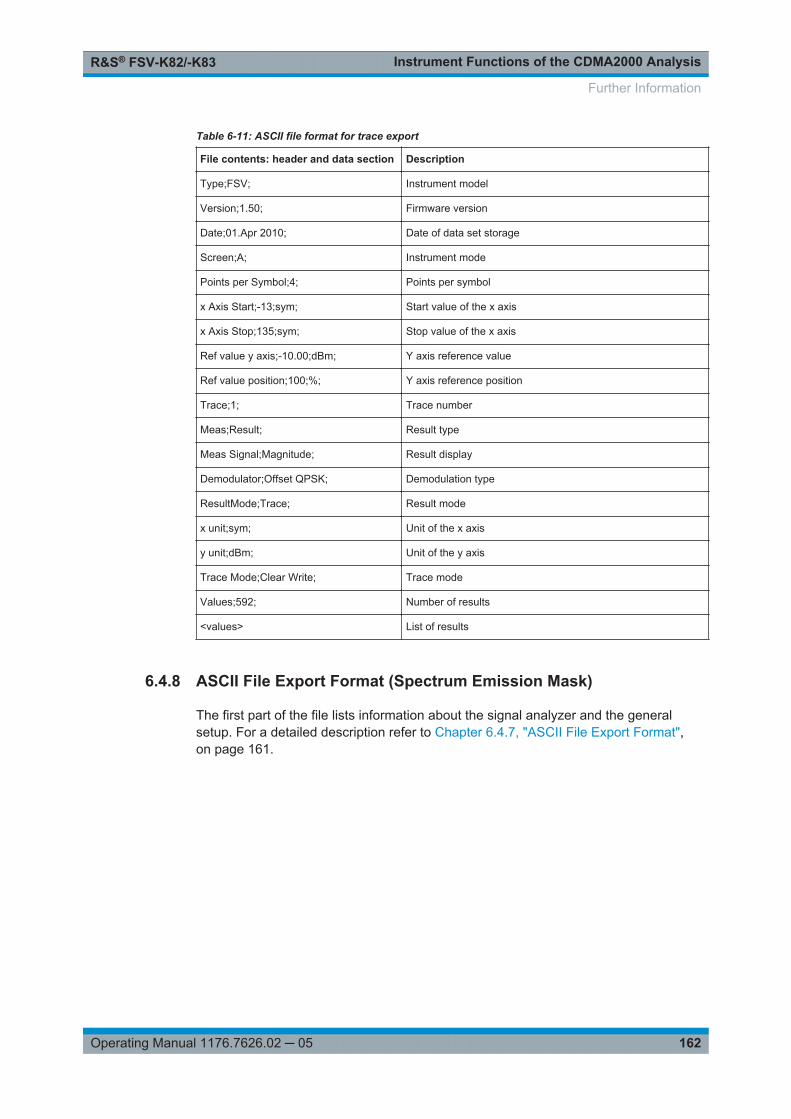
Instrument Functions of the CDMA2000 AnalysisR&S® FSV-K82/-K83
162Operating Manual 1176.7626.02 ─ 05
Table 6-11: ASCII file format for trace export
File contents: header and data section Description
Type;FSV; Instrument model
Version;1.50; Firmware version
Date;01.Apr 2010; Date of data set storage
Screen;A; Instrument mode
Points per Symbol;4; Points per symbol
x Axis Start;-13;sym; Start value of the x axis
x Axis Stop;135;sym; Stop value of the x axis
Ref value y axis;-10.00;dBm; Y axis reference value
Ref value position;100;%; Y axis reference position
Trace;1; Trace number
Meas;Result; Result type
Meas Signal;Magnitude; Result display
Demodulator;Offset QPSK; Demodulation type
ResultMode;Trace; Result mode
x unit;sym; Unit of the x axis
y unit;dBm; Unit of the y axis
Trace Mode;Clear Write; Trace mode
Values;592; Number of results
<values> List of results
6.4.8 ASCII File Export Format (Spectrum Emission Mask)
The first part of the file lists information about the signal analyzer and the generalsetup. For a detailed description refer to Chapter 6.4.7, "ASCII File Export Format",on page 161.
Further Information

Instrument Functions of the CDMA2000 AnalysisR&S® FSV-K82/-K83
163Operating Manual 1176.7626.02 ─ 05
File contents Description
RefType; CPOWER;
TxBandwidth;9540000;Hz
Filter State; ON;
Alpha;0.22;
reference range setup, for details see "EditReference Range" on page 115
PeaksPerRange;1;
Values;4;
evaluation list information
0;-22500000;-9270000;1000000;2986455000;-74.762840270996094;
-10.576210021972656;-45.762840270996094;PASS;
1;-9270000;-4770000;100000;2991405000;-100.17695617675781;
-35.990325927734375;-1.490325927734375;PASS
3;4770000;9270000;100000;3005445000;-100.17695617675781;
-35.990325927734375;-1.490325927734375;PASS;
4;9270000;22500000;1000000;3018225000;-74.762840270996094;
-10.576210021972656;-45.762840270996094;PASS;
information about each peak:
<range number>;
<start frequency>;
<stop frequency>;
<resolution bandwidth of range>;
<frequency of peak>;
<absolute power in dBm of peak>;
<relative power in dBc of peak
(related to the channel power)>;
<distance to the limit line in dB
(positive value means above the limit)>;
<limit fail (pass = 0, fail =1)>;
6.4.9 Format Description of Spectrum Emission Mask XML Files
The files for importing range settings are in XML format and therefore obey the rules ofthe XML standard. Below, the child nodes, attributes, and structure defined for the dataimport is described. Build your own XML files according to these conventions becausethe R&S FSV/FSVA can only interpret XML files of a known structure. For examplefiles look in the C:\r_s\instr\sem_std directory.
Figure 6-17: Example Spectrum emission mask standard file (PowerClass_39_43.xml)
Further Information

Instrument Functions of the CDMA2000 AnalysisR&S® FSV-K82/-K83
164Operating Manual 1176.7626.02 ─ 05
Be sure to follow the structure exactly as shown below or else the R&S FSV/FSVA isnot able to interpret the XML file and error messages are shown on the screen. There-fore, we recommend you make a copy of an existing file (see Save As Standard soft-key) and edit the copy of the file.Alternatively, edit the settings using the "Spectrum Emission Mask" softkey and theSweep List dialog box and save the XML file with the Save As Standard softkey after-wards. This way, no modifications have to be done in the XML file itself.
Basically, the file consists of three elements that can be defined:
● The "BaseFormat" element● The "PowerClass" element● The "Range" element
The "BaseFormat" element
It carries information about basic settings. In this element only the "ReferencePower"child node has any effects on the measurement itself. The other attributes and childnodes are used to display information about the Spectrum Emission Mask Standard onthe measurement screen. The child nodes and attributes of this element are shown inTable 6-12.
In the example above (PowerClass_39_43.xml underC:\r_s\instr\sem_std\WCDMA\3GPP, see Figure 6-17), these attributes aredefined as follows:
● Standard="W-CDMA 3GPP"● LinkDirection="DL"● PowerClass="(39,43)dBm"
The "PowerClass" element
It is embedded in the "BaseFormat" element and contains settings information aboutthe power classes. Up to four different power classes can be defined. For details referto the "Sweep List" softkey ("Sweep List" on page 110) and the corresponding parame-ter description. The child nodes and attributes of this element are shown in Table 6-13.
The "Range" element
This element is embedded in the "PowerClass" element. It contains the settings infor-mation of the range. There have to be at least three defined ranges: one referencerange and at least one range to either side of the reference range. The maximum num-ber of ranges is 20. Note that the R&S FSV/FSVA uses the same ranges in eachpower class. Therefore, the contents of the ranges of each defined power class have tobe identical to the first power class. An exception are the Start and Stop values of thetwo Limit nodes that are used to determine the power class. Note also, that there aretwo Limit nodes to be defined: one that gives the limit in absolute values and one inrelative values. Make sure units for the Start and Stop nodes are identical for eachLimit node.
Further Information

Instrument Functions of the CDMA2000 AnalysisR&S® FSV-K82/-K83
165Operating Manual 1176.7626.02 ─ 05
For details refer to the "Sweep List" softkey ("Sweep List" on page 110) and the corre-sponding parameter description. The child nodes and attributes of this element areshown in Table 6-14.
The following tables show the child nodes and attributes of each element and show if achild node or attribute is mandatory for the R&S FSV/FSVA to interpret the file or not.Since the hierarchy of the XML can not be seen in the tables, either view one of thedefault files already stored on the R&S FSV/FSVA in the "C:\r_s\instr\sem_std"directory or check the structure as shown below.
Below, a basic example of the structure of the file is shown, containing all mandatoryattributes and child nodes. Note that the "PowerClass" element and the range elementare themselves elements of the "BaseFormat" element and are to be inserted wherenoted. The separation is done here simply for reasons of a better overview. Also, noexample values are given here to allow a quick reference to the tables above. Italic fontshows the placeholders for the values.
● The "BaseFormat" element is structured as follows:– <RS_SEM_ACP_FileFormat Version=""1.0.0.0"">
<Name>"Standard"</Name><Instrument><Type>"Instrument Type"</Type><Application>"Application"</Application></Instrument><LinkDirection Name=""Name""><ReferencePower><Method>"Method"</Method></ReferencePower><PowerClass Index=""n""><!-- For contents of the PowerClass node seeTable 6-13 --><!-- Define up to four PowerClass nodes --></PowerClass></LinkDirection></RS_SEM_ACP_File>
● The "PowerClass" element is structured as follows:– <PowerClass Index=""n"">
<StartPower Unit=""dBm"" InclusiveFlag=""true"" Value=""StartPowerValue""/><StopPower Unit=""dBm"" InclusiveFlag=""false"" Value=""StopPowerValue""/><DefaultLimitFailMode>"Limit Fail Mode"</DefaultLimitFailMode><Range Index=""n""><!-- For contents of the Range node see Table 6-14 --><!-- Define up to twenty Range nodes --></Range>…</PowerClass>
● The "Range" element is structured as follows:– <Range Index=""n"">
<Name=""Name""><ChannelType>"Channel Type"</Channel Type>
Further Information

Instrument Functions of the CDMA2000 AnalysisR&S® FSV-K82/-K83
166Operating Manual 1176.7626.02 ─ 05
<WeightingFilter><Type>"FilterType"</Type><RollOffFactor>"Factor"</RollOffFactor><Bandwith>"Bandwidth"</Bandwidth></WeightingFilter><FrequencyRange><Start>"RangeStart"</Start><Stop>"RangeStop"</Stop></FrequencyRange><Limit><Start Unit=""Unit"" Value=""Value""/><Stop Unit=""Unit"" Value=""Value""/></Limit><Limit><Start Unit=""Unit"" Value=""Value""/><Stop Unit=""Unit"" Value=""Value""/></Limit><RBW Bandwidth=""Bandwidth"" Type=""FilterType""/><VBW Bandwidth=""Bandwidth""/><Detector>"Detector"</Detector><Sweep Mode=""SweepMode"" Time=""SweepTime""/><Amplitude><ReferenceLevel Unit=""dBm"" Value=""Value""/><RFAttenuation Mode=""Auto"" Unit=""dB"" Value=""Value""/><Preamplifier State=""State""/></Amplitude></Range>
Table 6-12: Attributes and child nodes of the BaseFormat element
Child Node Attribute Value Parameter Description Mand.
FileFormatVersion 1.0.0.0 Yes
Date YYYY-MM-DDHH:MM:SS
Date in ISO 8601 format No
Name <string> Name of the standard Yes
Instrument Type FSL Name of the instrument No
Application SA | K72 | K82 Name of the application No
LinkDirection Name Downlink | Uplink |None
Yes
ShortName DL | UL No
Reference-Power
Yes
Method TX Channel Power |
TX Channel PeakPower
Yes
Reference-Channel
<string> No
Further Information

Instrument Functions of the CDMA2000 AnalysisR&S® FSV-K82/-K83
167Operating Manual 1176.7626.02 ─ 05
Table 6-13: Attributes and child nodes of the PowerClass element
Child Node Attribute Value Parameter Description Mand.
StartPower Value <power in dBm> The start power must be equalto the stop power of the previ-ous power class. The Start-Power value of the first rangeis -200
Yes
Unit dBm Yes
InclusiveFlag true Yes
StopPower Value <power in dBm> The stop power must be equalto the start power of the nextpower class. The StopPowervalue of the last range is 200
Yes
Unit dBm
InclusiveFlag false Yes
DefaultLimitFailMode Absolute | Relative| Absolute and Rel-ative | Absolute orRelative
Yes
Table 6-14: Attributes and child nodes of the Range element (normal ranges)
Child Node Attribute Value Parameter Description Mand.
Index 0…19 Inde XE s are continuousand have to start with 0
Yes
Name <string> Name of the range Only if Referen-ceChannel con-tains a name andthe range is thereference range
Short-Name
<string> Short name of the range No
ChannelType TX | Adjacent Yes
WeightingFilter Only if Referen-cePower methodis TX ChannelPower and therange is the ref-erence range
Type RRC | CFilter Type of the weighting filter Yes
Roll Off Factor 0…1 Excess bandwidth of the fil-ter
Only if the filtertype is RRC
Bandwidth <bandwidth in Hz> Filter bandwidth Only if the filtertype is RRC
FrequencyRange Yes
Start <frequency in Hz> Start value of the range Yes
Stop <frequency in Hz> Stop value of the range Yes
Further Information

Instrument Functions of the CDMA2000 AnalysisR&S® FSV-K82/-K83
168Operating Manual 1176.7626.02 ─ 05
Child Node Attribute Value Parameter Description Mand.
Limit dBm/Hz | dBm |dBc | dBr | dB
A Range must containexactly two limit nodes; oneof the limit nodes has tohave a relative unit (e.g.dBc), the other one musthave an absolute unit (e.g.dBm)
Yes
Start Value <numeric_value> Power limit at start fre-quency
Yes
Unit dBm/Hz | dBm |dBc | dBr | dB
Sets the unit of the startvalue
Stop Value <numeric_value> Power limit at stop fre-quency
Unit dBm/Hz | dBm |dBc | dBr | dB
Sets the unit of the stopvalue
LimitFailMode Absolute | Relative| Absolute and Rel-ative | Absolute orRelative
If used, it has to be identicalto DefaultLimitFailMode
No
RBW Bandwidth <bandwidth in Hz> "RBW" on page 111 Yes
Type NORM | PULS |CFIL | RRC
No
VBW Bandwidth <bandwidth in Hz> "VBW" on page 112 Yes
Detector NEG | POS |SAMP | RMS |AVER | QUAS
If used, it has to be identicalin all ranges.
No
Sweep Mode Manual | Auto "Sweep Time Mode"on page 112
Yes
Time <time in sec> "Sweep Time" on page 112 No
Amplitude No
ReferenceLevel Value <power in dBm> "Ref. Level" on page 112 Yes, if the Refer-enceLevel childnode is used
Unit dBm Defines dBm as unit Yes, if the Refer-enceLevel nodeis used
RFAttenuation Mode Manual | Auto "RF Att. Mode" on page 112 Yes, if the Refer-enceLevel childnode is used
Preamplifier ON | OFF "Preamp" on page 112 Yes
6.4.10 Provided XML Files for the Spectrum Emission Mask Measurement
You can change the settings manually or via XML files. The XML files offer a quick wayto change the configuration. A set of ready-made XML files for different standards is
Further Information

Instrument Functions of the CDMA2000 AnalysisR&S® FSV-K82/-K83
169Operating Manual 1176.7626.02 ─ 05
already provided. For details see Table 6-15. You can also create and use your ownXML files (for details see Chapter 6.4.9, "Format Description of Spectrum EmissionMask XML Files", on page 163). All XML files are stored under "C:\r_s\instr\sem_std". Use the "Load Standard" softkey for quick access to theavailable XML files (see "Load Standard" on page 120).
Table 6-15: Provided XML files
Path XML file name Displayed standard character-istics*
cdma2000\DL default0.xml CDMA2000 BC0 DL
default1.xml CDMA2000 BC1 DL
cdma2000\UL default0.xml CDMA2000 BC0 UL
default1.xml CDMA2000 BC1 UL
WCDMA\3GPP\DL PowerClass_31_39.xml W-CDMA 3GPP (31,39)dBm DL
PowerClass_39_43.xml W-CDMA 3GPP (39,43)dBm DL
PowerClass_43_INF.xml W-CDMA 3GPP (43,INF)dBmDL
PowerClass_negINF_31.xml W-CDMA 3GPP (-INF,31)dBmDL
WIBRO\DL PowerClass_29_40.xml WiBro TTA (29,40)dBm DL
PowerClass_40_INF.xml WiBro TTA (40,INF)dBm DL
PowerClass_negINF_29.xml WiBro TTA (-INF,29)dBm DL
WIBRO\UL PowerClass_23_INF.xml WiBro TTA (23,INF)dBm UL
PowerClass_negINF_23.xml WiBro TTA (23,INF)dBm UL
WIMAX\DL\ETSI\…MHz (1.75MHz, 2.00 MHz, 3.5 MHz, 7.00MHz, 14.00 MHz, 28 MHz)
System_Type_E.xml WIMAX System Type E DL
System_Type_F.xml WIMAX System Type F DL
System_Type_G.xml WIMAX System Type G DL
WIMAX\DL\IEEE 10MHz.xml WIMAX 10MHz DL
20MHz.xml WIMAX 20MHz DL
WIMAX\UL\ETSI…MHz (1.75MHz, 2.00 MHz, 3.5 MHz, 7.00MHz, 14.00 MHz, 28 MHz)
System_Type_E.xml WIMAX System Type E UL
System_Type_F.xml WIMAX System Type F UL
System_Type_G.xml WIMAX System Type G UL
WIMAX\UL\IEEE 10MHz.xml WIMAX 10MHz UL
20MHz.xml WIMAX 20MHz UL
WLAN\802_11_TURBO ETSI.xml IEEE 802.11
IEEE.xml IEEE 802.11
Further Information

Instrument Functions of the CDMA2000 AnalysisR&S® FSV-K82/-K83
170Operating Manual 1176.7626.02 ─ 05
Path XML file name Displayed standard character-istics*
WLAN\802_11a ETSI.xml IEEE 802.11a
IEEE.xml IEEE 802.11a
WLAN\802_11b IEEE.xml IEEE 802.11b
WLAN\802_11j_10MHz ETSI.xml IEEE.802.11j
IEEE.xml IEEE.802.11j
WLAN\802_11j_20MHz ETSI.xml IEEE 802.11j
IEEE.xml IEEE 802.11j
EUTRA-LTE\DL\CategoryA\ BW_01_4_MHz__CFhigher1GHz.xml
LTE Cat. A >1GHz DL
EUTRA-LTE\DL\CategoryA\ BW_01_4_MHz__CFlower1GHz.xml LTE Cat. A <1GHz DL
EUTRA-LTE\DL\CategoryA\ BW_03_0_MHz__CFhigher1GHz.xml
LTE Cat. A >1GHz DL
EUTRA-LTE\DL\CategoryA\ BW_03_0_MHz__CFlower1GHz.xml LTE Cat. A <1GHz DL
EUTRA-LTE\DL\CategoryA\ BW_05_0_MHz__CFhigher1GHz.xml
LTE Cat. A >1GHz DL
EUTRA-LTE\DL\CategoryA\ BW_05_0_MHz__CFlower1GHz.xml LTE Cat. A <1GHz DL
EUTRA-LTE\DL\CategoryA\ BW_10_0_MHz__Cfhigher1GHz.xml LTE Cat. A >1GHz DL
EUTRA-LTE\DL\CategoryA\ BW_10_0_MHz__Cflower1GHz.xml LTE Cat. A >1GHz DL
EUTRA-LTE\DL\CategoryA\ BW_15_0_MHz__CFhigher1GHz.xml
LTE Cat. A >1GHz DL
EUTRA-LTE\DL\CategoryA\ BW_15_0_MHz__CFlower1GHz.xml LTE Cat. A <1GHz DL
EUTRA-LTE\DL\CategoryA\ BW_20_0_MHz__CFhigher1GHz.xml
LTE Cat. A >1GHz DL
EUTRA-LTE\DL\CategoryA\ BW_20_0_MHz__CFlower1GHz.xml LTE Cat. A <1GHz DL
EUTRA-LTE\DL\CategoryB\ BW_01_4_MHz__CFhigher1GHz.xml
LTE Cat. B >1GHz DL
EUTRA-LTE\DL\CategoryB\ BW_01_4_MHz__CFlower1GHz.xml LTE Cat. B <1GHz DL
EUTRA-LTE\DL\CategoryB\ BW_03_0_MHz__CFhigher1GHz.xml
LTE Cat. B >1GHz DL
EUTRA-LTE\DL\CategoryB\ BW_03_0_MHz__CFlower1GHz.xml LTE Cat. B <1GHz DL
EUTRA-LTE\DL\CategoryB\ BW_05_0_MHz__CFhigher1GHz.xml
LTE Cat. B >1GHz DL
EUTRA-LTE\DL\CategoryB\ BW_05_0_MHz__CFlower1GHz.xml LTE Cat. B <1GHz DL
EUTRA-LTE\DL\CategoryB\ BW_10_0_MHz__Cfhigher1GHz.xml LTE Cat. B >1GHz DL
EUTRA-LTE\DL\CategoryB\ BW_10_0_MHz__Cflower1GHz.xml LTE Cat. B >1GHz DL
EUTRA-LTE\DL\CategoryB\ BW_15_0_MHz__CFhigher1GHz.xml
LTE Cat. B >1GHz DL
Further Information

Instrument Functions of the CDMA2000 AnalysisR&S® FSV-K82/-K83
171Operating Manual 1176.7626.02 ─ 05
Path XML file name Displayed standard character-istics*
EUTRA-LTE\DL\CategoryB\ BW_15_0_MHz__CFlower1GHz.xml LTE Cat. B <1GHz DL
EUTRA-LTE\DL\CategoryB\ BW_20_0_MHz__CFhigher1GHz.xml
LTE Cat. B >1GHz DL
EUTRA-LTE\DL\CategoryB\ BW_20_0_MHz__CFlower1GHz.xml LTE Cat. B <1GHz DL
EUTRA-LTE\UL\Standard\ BW_05_0_MHz.xml LTE UL
EUTRA-LTE\UL\Standard\ BW_10_0_MHz.xml LTE UL
EUTRA-LTE\UL\Standard\ BW_15_0_MHz.xml LTE UL
EUTRA-LTE\UL\Standard\ BW_20_0_MHz.xml LTE UL
*Used abbreviations:
BC: band class
UL: uplink
DL: downlink
TTA: Telecommunications Technology Association
6.4.11 Ranges and Range Settings
In the Spectrum Emission Mask measurements, a range defines a segment for whichyou can define the following parameters separately:
● Start and stop frequency● RBW● VBW● Sweep time● Sweep points● Reference level● Attenuator settings● Limit values
Via the sweep list, you define the ranges and their settings. For details on settings referto "Sweep List dialog box" on page 110.
For details on defining the limits (masks) see the base unit description "Working withLines in SEM".
The following rules apply to ranges:
● The minimum span of a range is 20 Hz.● The individual ranges must not overlap (but need not directly follow one another).● The maximum number of ranges is 20.● A minimum of three ranges is mandatory.
Further Information

Instrument Functions of the CDMA2000 AnalysisR&S® FSV-K82/-K83
172Operating Manual 1176.7626.02 ─ 05
● The reference range cannot be deleted (it is marked in blue color).● The reference range has to be centered on the center frequency.● The minimum span of the reference range is given by the current TX Bandwidth.● Frequency values for each range have to be defined relative to the center fre-
quency.
In order to change the start frequency of the first range or the stop frequency of the lastrange, select the appropriate span with the SPAN key. If you set a span that is smallerthan the overall span of the ranges, the measurement includes only the ranges that liewithin the defined span and have a minimum span of 20 Hz. The first and last rangesare adapted to the given span as long as the minimum span of 20 Hz is not violated.
Symmetrical rangesYou can easily define a sweep list with symmetrical range settings, i.e. the ranges tothe left and right of the center range are defined symmectrically. In the "Sweep List"menu, select the "Symmetrical Setup" softkey to activate symmetrical setup mode. Thecurrent sweep list configuration is changed to define a symmetrical setup regarding thereference range. The number of ranges to the left of the reference range is reflected tothe right, i.e. any missing ranges on the right are inserted, while superfluous rangesare removed. The values in the ranges to the right of the reference range are adaptedsymmetrically to those in the left ranges.For details see "Symmetric Setup" on page 115.Symmetrical ranges fulfull the conditions required for "Fast SEM" mode (see Chap-ter 6.4.12, "Fast Spectrum Emission Mask Measurements", on page 172).
6.4.12 Fast Spectrum Emission Mask Measurements
In order to improve the performance of the R&S FSV/FSVA for spectrum emissionmask measurements, a "Fast SEM" mode is available. If this mode is activated, sev-eral consecutive ranges with identical sweep settings are combined to one sweepinternally, which makes the measurement considerably more efficient. The displayedresults remain unchanged and still consist of several ranges. Thus, measurement set-tings that apply only to the results, such as limits or transducer factors, can neverthe-less be defined individually for each range.
Prerequisites
"Fast SEM" mode is available if the following criteria apply:
● The frequency ranges are consecutive, without frequency gaps● The following sweep settings are identical:
– "Filter Type", see "Filter Type" on page 111– "RBW", see "RBW" on page 111– "VBW", see "VBW" on page 112– "Sweep Time Mode", see "Sweep Time Mode" on page 112– "Ref Level", see "Ref. Level" on page 112
Further Information

Instrument Functions of the CDMA2000 AnalysisR&S® FSV-K82/-K83
173Operating Manual 1176.7626.02 ─ 05
– "Rf Att. Mode", see "RF Att. Mode" on page 112– "RF Attenuator", see "RF Att. Mode" on page 112– "Preamp", see "Preamp" on page 112
Activating Fast SEM mode
"Fast SEM" mode is activated in the sweep list (see "Fast SEM" on page 111) or usinga remote command. Activating the mode for one range automatically activates it for allranges in the sweep list.
In the provided XML files for the Spectrum Emission Mask measurement, "Fast SEM"mode is activated by default.
SCPI command:
[SENSe:]ESPectrum:HighSPeed on page 256
Consequences
When the "Fast SEM" mode is activated, the ranges for which these criteria apply aredisplayed as one single range. The sweep time is defined as the sum of the individualsweep times, initially, but can be changed. When the "Fast SEM" mode is deactivated,the originally defined individual sweep times are reset.
If "Symmetrical Setup" mode is active when "Fast SEM" mode is activated, not allsweep list settings can be configured symmetrically automatically (see also "SymmetricSetup" on page 115).
Any other changes to the sweep settings of the combined range are applied to eachincluded range and remain changed even after deactivating "Fast SEM" mode.
Further Information
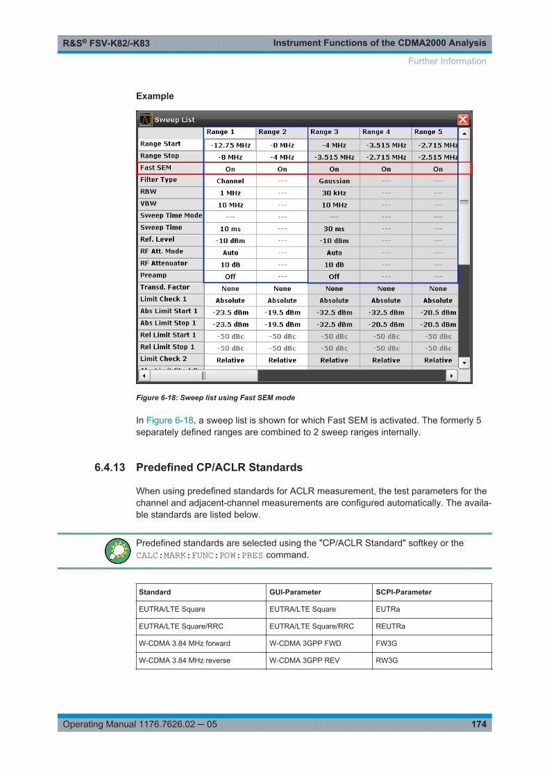
Instrument Functions of the CDMA2000 AnalysisR&S® FSV-K82/-K83
174Operating Manual 1176.7626.02 ─ 05
Example
Figure 6-18: Sweep list using Fast SEM mode
In Figure 6-18, a sweep list is shown for which Fast SEM is activated. The formerly 5separately defined ranges are combined to 2 sweep ranges internally.
6.4.13 Predefined CP/ACLR Standards
When using predefined standards for ACLR measurement, the test parameters for thechannel and adjacent-channel measurements are configured automatically. The availa-ble standards are listed below.
Predefined standards are selected using the "CP/ACLR Standard" softkey or theCALC:MARK:FUNC:POW:PRES command.
Standard GUI-Parameter SCPI-Parameter
EUTRA/LTE Square EUTRA/LTE Square EUTRa
EUTRA/LTE Square/RRC EUTRA/LTE Square/RRC REUTRa
W-CDMA 3.84 MHz forward W-CDMA 3GPP FWD FW3G
W-CDMA 3.84 MHz reverse W-CDMA 3GPP REV RW3G
Further Information

Instrument Functions of the CDMA2000 AnalysisR&S® FSV-K82/-K83
175Operating Manual 1176.7626.02 ─ 05
Standard GUI-Parameter SCPI-Parameter
CDMA IS95A forward CDMA IS95A FWD F8CD | FIS95a
CDMA IS95A reverse CDMA IS95A REV R8CD | RIS95a
CDMA IS95C Class 0 forward*) CDMA IS95C Class 0 FWD FIS95c0
CDMA IS95C Class 0 reverse*) CDMA IS95C Class 0 REV RIS95c0
CDMA J-STD008 forward CDMA J-STD008 FWD F19C | FJ008
CDMA J-STD008 reverse CDMA J-STD008 REV R19C | RJ008
CDMA IS95C Class 1 forward*) CDMA IS95C Class 1 FWD FIS95c1
CDMA IS95C Class 1 reverse*) CDMA IS95C Class 1 REV RIS95c1
CDMA 2000 CDMA 2000 S2CD
TD-SCDMA forward TD SCDMA FWD FTCD | TCDMa
TD-SCDMA reverse TD SCDMA REV RTCD
WLAN 802.11A WLAN 802.11A AWLan
WLAN 802.11B WLAN 802.11B BWLan
WiMAX WiMAX WiMAX
WIBRO WIBRO WIBRO
GSM GSM GSM
RFID 14443 RFID 14443 RFID14443
TETRA TETRA TETRA
PDC PDC PDC
PHS PHS PHS
CDPD CDPD CDPD
APCO-25 Phase 2 APCO-25 P2 PAPCo25
For the R&S FSV/FSVA, the channel spacing is defined as the distance between thecenter frequency of the adjacent channel and the center frequency of the transmissionchannel. The definition of the adjacent-channel spacing in standards IS95C and CDMA2000 is different. These standards define the adjacent-channel spacing from the centerof the transmission channel to the closest border of the adjacent channel. This defini-tion is also used for the R&S FSV/FSVA if the standards marked with an asterisk *) areselected.
6.4.14 Optimized Settings for CP/ACLR Test Parameters
The "Adjust Settings" softkey (see "Adjust Settings" on page 108) automatically optimi-zes all instrument settings for the selected channel configuration, as described in thefollowing:
Further Information

Instrument Functions of the CDMA2000 AnalysisR&S® FSV-K82/-K83
176Operating Manual 1176.7626.02 ─ 05
● Frequency spanThe frequency span must at least cover the channels to be measured plus a mea-surement margin of approx. 10 %.If the frequency span is large in comparison to the channel bandwidth (or the adja-cent-channel bandwidths) being examined, only a few points on the trace are avail-able per channel. This reduces the accuracy of the waveform calculation for thechannel filter used, which has a negative effect on the measurement accuracy. It istherefore strongly recommended that the formulas mentioned be taken into consid-eration when selecting the frequency span.For channel power measurements the Adjust Settings softkey sets the frequencyspan as follows:"(No. of transmission channels – 1) x transmission channel spacing + 2 x transmis-sion channel bandwidth + measurement margin"For adjacent-channel power measurements, the Adjust Settings softkey sets thefrequency span as a function of the number of transmission channels, the trans-mission channel spacing, the adjacent-channel spacing, and the bandwidth of oneof adjacent-channels ADJ, ALT1 or ALT2, whichever is furthest away from thetransmission channels:"(No. of transmission channels – 1) x transmission channel spacing + 2 x (adja-cent-channel spacing + adjacent-channel bandwidth) + measurement margin"The measurement margin is approx. 10 % of the value obtained by adding thechannel spacing and the channel bandwidth.
● Resolution bandwidth (RBW)To ensure both, acceptable measurement speed and required selection (to sup-press spectral components outside the channel to be measured, especially of theadjacent channels), the resolution bandwidth must not be selected too small or toolarge. As a general approach, the resolution bandwidth is to be set to valuesbetween 1% and 4% of the channel bandwidth.A larger resolution bandwidth can be selected if the spectrum within the channel tobe measured and around it has a flat characteristic. In the standard setting, e.g. forstandard IS95A REV at an adjacent channel bandwidth of 30 kHz, a resolutionbandwidth of 30 kHz is used. This yields correct results since the spectrum in theneighborhood of the adjacent channels normally has a constant level.With the exception of the IS95 CDMA standards, the Adjust Settings softkey setsthe resolution bandwidth (RBW) as a function of the channel bandwidth:"RBW ≤ 1/40 of channel bandwidth"The maximum possible resolution bandwidth (with respect to the requirement RBW≤ 1/40) resulting from the available RBW steps (1, 3) is selected.
● Video bandwidth (VBW)For a correct power measurement, the video signal must not be limited in band-width. A restricted bandwidth of the logarithmic video signal would cause signalaveraging and thus result in a too low indication of the power (-2.51 dB at very lowvideo bandwidths). The video bandwidth should therefore be selected at least threetimes the resolution bandwidth:"VBW ≥ 3 x RBW"The Adjust Settings softkey sets the video bandwidth (VBW) as a function of thechannel bandwidth (see formula above) and the smallest possible VBW with regardto the available step size will be selected.
● Detector
Further Information

Instrument Functions of the CDMA2000 AnalysisR&S® FSV-K82/-K83
177Operating Manual 1176.7626.02 ─ 05
The Adjust Settings softkey selects the RMS detector. This detector is selectedsince it correctly indicates the power irrespective of the characteristics of the signalto be measured. The whole IF envelope is used to calculate the power for eachmeasurement point. The IF envelope is digitized using a sampling frequency whichis at least five times the resolution bandwidth which has been selected. Based onthe sample values, the power is calculated for each measurement point using thefollowing formula:
where:"si = linear digitized video voltage at the output of the A/D converter""N = number of A/D converter values per measurement point""PRMS = power represented by a measurement point"When the power has been calculated, the power units are converted into decibelsand the value is displayed as a measurement point.In principle, the sample detector would be possible as well. Due to the limited num-ber of measurement points used to calculate the power in the channel, the sampledetector would yield less stable results.
● Trace averagingThe Adjust Settings softkey switches off this function. Averaging, which is oftenperformed to stabilize the measurement results, leads to a too low level indicationand should therefore be avoided. The reduction in the displayed power depends onthe number of averages and the signal characteristics in the channel to be mea-sured.
● Reference levelThe Adjust Settings softkey does not influence the reference level. It can be adjus-ted separately using the "Adjust Ref Lvl" softkey (see "Adjust Ref Lvl"on page 100).
Further Information

Remote Commands of the CDMA2000 BTS AnalysisR&S® FSV-K82/-K83
178Operating Manual 1176.7626.02 ─ 05
7 Remote Commands of the CDMA2000 BTSAnalysisThis chapter describes the remote commands specific to the CDMA2000 Analysisoptions (R&S FSV-K82/-K83). The abbreviation CDMA stands for the operating modeof this option. For details on conventions used in this chapter refer to Chapter 7.1,"Notation", on page 179.
For further information on analyzer or basic settings commands, refer to the corre-sponding subsystem in the base unit description.
In particular, the following subsystems are identical to the base unit; refer to the baseunit description:
● CALCulate:DELTamarker● CALCulate:MARKer (except for the specific commands described in Chapter 7.2,
"CALCulate Subsystem", on page 181)● DISPlay subsystem● FORMat subsystem● INITiate subsystem● INPut subsystem● MMEM subsystem● OUTput subsystem● SENSe subsystem (except for the specific commands described in Chapter 7.6,
"SENSe Subsystem", on page 243)● TRIGger subsystem
7.1 Notation......................................................................................................................179
7.2 CALCulate Subsystem..............................................................................................181
7.2.1 CALCulate:FEED Subsystem..................................................................................... 182
7.2.2 CALCulate:MARKer:FUNCtion Subsystem.................................................................184
7.2.3 Other CALCulate Commands Referenced in this Manual...........................................191
7.3 CONFigure Subsystem............................................................................................. 224
7.3.1 CONFigure:CDPower Subsystem (K82/K84)..............................................................224
7.4 DISPlay Subsystem...................................................................................................235
7.5 INSTrument Subsystem............................................................................................242
7.6 SENSe Subsystem.................................................................................................... 243
7.6.1 SENSe:CDPower Subsystem..................................................................................... 243
7.6.2 Other SENSe Commands Referenced in this Manual................................................ 252
7.7 STATus subsystem...................................................................................................290
7.8 TRACe Subsystem.................................................................................................... 291

Remote Commands of the CDMA2000 BTS AnalysisR&S® FSV-K82/-K83
179Operating Manual 1176.7626.02 ─ 05
7.9 Other Commands Referenced in this Manual........................................................ 300
7.9.1 INPut commands.........................................................................................................300
7.9.2 TRIGger Commands................................................................................................... 307
7.9.3 Other Referenced Commands.................................................................................... 310
7.1 Notation
In the following sections, all commands implemented in the instrument are first listedand then described in detail, arranged according to the command subsystems. Thenotation is adapted to the SCPI standard. The SCPI conformity information is includedin the individual description of the commands.
Individual Description
The individual description contains the complete notation of the command. An examplefor each command, the *RST value and the SCPI information are included as well.
The options and operating modes for which a command can be used are indicated bythe following abbreviations:
Abbreviation Description
A spectrum analysis
A-F spectrum analysis – span > 0 only (frequency mode)
A-T spectrum analysis – zero span only (time mode)
ADEMOD analog demodulation (option R&S FSV-K7)
BT Bluetooth (option R&S FSV-K8)
CDMA CDMA 2000 base station measurements (option R&S FSV-K82)
EVDO 1xEV-DO base station analysis (option R&S FSV-K84)
GSM GSM/Edge measurements (option R&S FSV-K10)
IQ IQ Analyzer mode
OFDM WiMAX IEEE 802.16 OFDM measurements (option R&S FSV-K93)
OFDMA/WiBro WiMAX IEEE 802.16e OFDMA/WiBro measurements (option R&S FSV-K93)
NF Noise Figure measurements (R&S FSV-K30)
PHN Phase Noise measurements (R&S FSV-K40)
PSM Power Sensor measurements (option R&S FSV-K9)
SFM Stereo FM measurements (optionR&S FSV-K7S)
SPECM Spectogram mode (option R&S FSV-K14)
TDS TD-SCDMA base station / UE measurements (option R&S FSV-K76/K77)
VSA Vector Signal Analysis (option R&S FSV-K70)
Notation

Remote Commands of the CDMA2000 BTS AnalysisR&S® FSV-K82/-K83
180Operating Manual 1176.7626.02 ─ 05
WCDMA 3GPP Base Station measurements (option R&S FSV-K72), 3GPP UE measure-ments (option R&S FSV-K73)
WLAN WLAN TX measurements (option R&S FSV-K91)
The spectrum analysis mode is implemented in the basic unit. For the other modes, thecorresponding options are required.
Upper/Lower Case Notation
Upper/lower case letters are used to mark the long or short form of the key words of acommand in the description. The instrument itself does not distinguish between upperand lower case letters.
Special Characters
| A selection of key words with an identical effect exists for several commands. These keywordsare indicated in the same line; they are separated by a vertical stroke. Only one of these key-words needs to be included in the header of the command. The effect of the command is inde-pendent of which of the keywords is used.
Example:
SENSe:FREQuency:CW|:FIXedThe two following commands with identical meaning can be created. They set the fre-quency of the fixed frequency signal to 1 kHz:
SENSe:FREQuency:CW 1E3SENSe:FREQuency:FIXed 1E3A vertical stroke in parameter indications marks alternative possibilities in the sense of"or". The effect of the command differs, depending on which parameter is used.
Example: Selection of the parameters for the command
[SENSe<1…4>:]AVERage<1…4>:TYPE VIDeo | LINear
[] Key words in square brackets can be omitted when composing the header. The full commandlength must be accepted by the instrument for reasons of compatibility with the SCPI standards.
Parameters in square brackets can be incorporated optionally in the command or omitted aswell.
{} Parameters in braces can be incorporated optionally in the command, either not at all, once orseveral times.
Description of Parameters
Due to the standardization, the parameter section of SCPI commands consists alwaysof the same syntactical elements. SCPI has therefore specified a series of definitions,which are used in the tables of commands. In the tables, these established definitionsare indicated in angled brackets (<…>) and is briefly explained in the following.
Notation

Remote Commands of the CDMA2000 BTS AnalysisR&S® FSV-K82/-K83
181Operating Manual 1176.7626.02 ─ 05
For details see the chapter "SCPI Command Structure" in the base unit description.
<Boolean>
This keyword refers to parameters which can adopt two states, "on" and "off". The "off"state may either be indicated by the keyword OFF or by the numeric value 0, the "on"state is indicated by ON or any numeric value other than zero. Parameter queries arealways returned the numeric value 0 or 1.
<numeric_value> <num>
These keywords mark parameters which may be entered as numeric values or be setusing specific keywords (character data). The following keywords given below are per-mitted:
● MAXimum: This keyword sets the parameter to the largest possible value.● MINimum: This keyword sets the parameter to the smallest possible value.● DEFault: This keyword is used to reset the parameter to its default value.● UP: This keyword increments the parameter value.● DOWN: This keyword decrements the parameter value.
The numeric values associated to MAXimum/MINimum/DEFault can be queried byadding the corresponding keywords to the command. They must be entered followingthe quotation mark.
Example:
SENSe:FREQuency:CENTer? MAXimumReturns the maximum possible numeric value of the center frequency as result.
<arbitrary block program data>
This keyword is provided for commands the parameters of which consist of a binarydata block.
7.2 CALCulate Subsystem
The CALCulate subsystem contains commands for converting instrument data, trans-forming and carrying out corrections. These functions are carried out subsequent todata acquisition, i.e. following the SENSe subsystem.
Note that most commands in the CALCulate subsystem are identical to the base unit;only the commands specific to this option are described here.
7.2.1 CALCulate:FEED Subsystem..................................................................................... 182
7.2.2 CALCulate:MARKer:FUNCtion Subsystem.................................................................184
7.2.3 Other CALCulate Commands Referenced in this Manual...........................................191
7.2.3.1 CALCulate:DELTamarker subsystem......................................................................... 191
CALCulate Subsystem

Remote Commands of the CDMA2000 BTS AnalysisR&S® FSV-K82/-K83
182Operating Manual 1176.7626.02 ─ 05
7.2.3.2 CALCulate:LIMit subsystem........................................................................................199
7.2.3.3 CALCulate:LIMit:ESPectrum subsystem.....................................................................206
7.2.3.4 CALCulate:MARKer subsystem.................................................................................. 211
7.2.3.5 CALCulate:PSE subsystem........................................................................................ 218
7.2.3.6 CALCulate:STATistics subsystem.............................................................................. 219
7.2.3.7 Other Referenced CALCulate Commands..................................................................223
7.2.1 CALCulate:FEED Subsystem
The CALCulate:FEED subsystem selects the result display for the measurementdata. This corresponds to the result display selection in manual operation.
CALCulate<n>:FEED..................................................................................................... 182
CALCulate<n>:FEED <result display>
This command selects the result display for the measured data.
In MS mode, the results are displayed for the branch selected by [SENSe:]CDPower:MAPPing.
Suffix: <n>
.1...4screen
CALCulate Subsystem

Remote Commands of the CDMA2000 BTS AnalysisR&S® FSV-K82/-K83
183Operating Manual 1176.7626.02 ─ 05
Parameters:<result display> 'XPOW:CDP' | 'XPOW:CDP:RAT' | 'XPOW:CDEP' |
'XTIM:CDP:ERR:CTABle' | 'XTIM:CDP:PVSLot' |'XTIM:CDP:ERR:SUMMary' | 'XTIM:CDP:MACCuracy' |'XTIM:CDP:ERR:PCDomain' |'XTIM:CDP:SYMB:CONStellation' | 'XTIM:CDP:SYMB:EVM' |'XTIM:CDP:BSTReam' | 'XTIM:CDP:COMP:CONStellation' |'XTIM:CDP:PVSYmbol' | 'XTIMe:CDPower:CHIP:MAGNitude' |'XTIMe:CDPower:CHIP:PHASe' |'XTIMe:CDPower:SYMBol:EVM:PHASe' |'XTIMe:CDPower:SYMBol:EVM:MAGNitude''XPOW:CDP'Code Domain Power (CDP) result display (absolute)'XPOW:CDP:RAT'Code Domain Power (CDP) result display (relative)'XTIM:CDP:BSTReam'Channel Bitstream result display'XTIM:CDP:COMP:CONStellation'Composite Constellation result display'XPOW:CDEP'Code Domain Error Power (CDEP) result display'XTIM:CDP:ERR:CTABle'Channel Table result display'XTIM:CDP:ERR:PCDomain'Peak Code Domain Error result display'XTIM:CDP:ERR:SUMMary'Result Summary result display'XTIM:CDP:MACCuracy'Composite EVM result display'XTIM:CDP:PVSLot'Power versus Power Control Group (PCG) result display'XTIM:CDP:PVSYmbol'Power versus Symbol result display'XTIM:CDP:SYMB:CONStellation'Channel Constellation result display'XTIM:CDP:SYMB:EVM'Symbol Error Vector Magnitude result display'XTIMe:CDPower:SYMBol:EVM:MAGNitude'Result display of the symbol magnitude error'XTIMe:CDPower:SYMBol:EVM:PHASe'Result display of the symbol phase error'XTIMe:CDP:CHIP:MAGNitude'Result display magnitude error versus chip'XTIMe:CDPower:CHIP:PHASe'
CALCulate Subsystem

Remote Commands of the CDMA2000 BTS AnalysisR&S® FSV-K82/-K83
184Operating Manual 1176.7626.02 ─ 05
Result display phase error versus chip*RST: 'XPOW:CDP:RAT' (screen A),
‘'XTIM:CDP:ERR:SUMM’ (screen B)
Example: CALC2:FEED 'XTIM:CDP:MACC'Selects the Composite EVM result display for measurementscreen 2
Usage: SCPI confirmed
Mode: CDMA
Manual operation: See "Code Power" on page 76
7.2.2 CALCulate:MARKer:FUNCtion Subsystem
The CALCulate:MARKer:FUNCtion subsystem checks the marker functions in theinstrument.
CALCulate<n>:MARKer<m>:FUNCtion:CDPower[:BTS]:RESult?........................................184CALCulate<n>:MARKer<m>:FUNCtion:CENTer................................................................186CALCulate<n>:MARKer<m>:FUNCtion:PICH....................................................................186CALCulate<n>:MARKer<m>:FUNCtion:POWer:MODE...................................................... 187CALCulate<n>:MARKer<m>:FUNCtion:POWer:RESult?....................................................187CALCulate<n>:MARKer<m>:FUNCtion:POWer:RESult:PHZ.............................................. 188CALCulate<n>:MARKer<m>:FUNCtion:POWer:SELect..................................................... 189CALCulate<n>:MARKer<m>:FUNCtion:TDPIch.................................................................190
CALCulate<n>:MARKer<m>:FUNCtion:CDPower[:BTS]:RESult?
This command queries the results of the code domain measurement for the selectedchannel. The channel is selected via the [SENSe:]CDPower:CODE command.
For a description of the result types refer to Chapter 6.1.3, "Code Domain AnalysisResults", on page 38.
Suffix: <n>
.1...4window
<m> irrelevant
CALCulate Subsystem

Remote Commands of the CDMA2000 BTS AnalysisR&S® FSV-K82/-K83
185Operating Manual 1176.7626.02 ─ 05
Parameters:<Result> SLOT | PTOTal | PPICh | RHO | MACCuracy | PCDerror |
ACTive | FERRor | FERPpm | CERRor | TFRame I IQOFfset |IQIMbalance | SRATe | CHANnel | SFACtor | TOFFset |POFFset | CDPabsolute | CDPRelative | EVMRms | EVMPeak |DMTypeSLOTPCG numberPTOTalTotal power in dBmPPIChPilot power in dBmRHORHOMACCuracyComposite EVM in %PCDerrorPeak code domain error in dBACTiveNumber of active channelsFERRorFrequency error in HzFERPpmFrequency error in ppmCERRorChip rate error in ppmTFRame ITrigger to frameIQOFfsetIQ offset in %IQIMbalanceIQ imbalance in %SRATeSymbol rate in kspsCHANnelChannel numberSFACtorSpreading factor of channelTOFFsetTiming offset in sPOFFsetPhase offset in radCDPabsoluteChannel power absolute in dBmCDPRelative
CALCulate Subsystem

Remote Commands of the CDMA2000 BTS AnalysisR&S® FSV-K82/-K83
186Operating Manual 1176.7626.02 ─ 05
Channel power relative in dB (relative to total or PICH power,refer to CDP:PREF command)
EVMRmsError vector magnitude RMS in %EVMPeakError vector mag. peak in %DMTypeDomain type
Example: CALC:MARK:FUNC:CDP:RES? PTOTReads out total power.CDP:SLOT 2Selects power control group 2.CDP:CODE 11Selects code number 11.CALC:MARK:FUNC:CDP:RES? EVMRReads out Composite EVM of the code with number 11 in PCG2.
Usage: Query only
Mode: CDMA
CALCulate<n>:MARKer<m>:FUNCtion:CENTer
This command matches the center frequency to the frequency of a marker.
If you use the command in combination with a delta marker, that delta marker is turnedinto a normal marker.
Suffix: <n>
.Selects the measurement window.
<m> Selects the marker.
Example: CALC:MARK2:FUNC:CENTSets the center frequency to the frequency of marker 2.
Manual operation: See "Center =Mkr Freq (span > 0)" on page 91
CALCulate<n>:MARKer<m>:FUNCtion:PICH
This command sets the marker to channel 0.64.
Suffix: <n>
.1...4window
<m> 1...4marker to be set to the pilot channel
CALCulate Subsystem
Remote Commands of the CDMA2000 BTS AnalysisR&S® FSV-K82/-K83
187Operating Manual 1176.7626.02 ─ 05
Example: CALC:MARK:FUNC:PICHActivates marker and positions it at pilot 0.64.CALC:MARK:Y?Queries value of the relative Code Domain Power of the pilotchannel.
Usage: Event
Mode: CDMA
Manual operation: See "F-PICH (BTS mode only)" on page 90See "PICH (MS mode only)" on page 90
CALCulate<n>:MARKer<m>:FUNCtion:POWer:MODE <Mode>
This commands defines the method by which the channel power values are calculatedfrom the current trace in the window specified by the suffix <n>.
Suffix: <n>
.Selects the measurement window.
<m> Selects the marker.
Parameters:<Mode> WRITe | MAXHold
WRITeThe channel power and the adjacent channel powers are calcu-lated directly from the current traceMAXHoldThe power values are calculated from the current trace andcompared with the previous power value using a maximum algo-rithm.
Example: CALC:MARK:FUNC:POW:MODE MAXHSets the Maxhold channel power mode.
Manual operation: See "Clear/Write" on page 107See "Max Hold" on page 108
CALCulate<n>:MARKer<m>:FUNCtion:POWer:RESult? <ResultType>
This command queries the result of the performed power measurement in the windowspecified by the suffix <n>. If necessary, the measurement is switched on prior to thequery.
The channel spacings and channel bandwidths are configured in the SENSe:POWersubsystem.
To obtain a correct result, a complete sweep with synchronization to the end of thesweep must be performed before a query is output. Synchronization is possible only inthe single sweep mode.
Suffix: <n>
.Selects the measurement window.
CALCulate Subsystem

Remote Commands of the CDMA2000 BTS AnalysisR&S® FSV-K82/-K83
188Operating Manual 1176.7626.02 ─ 05
<m> Selects the marker.
Parameters:<ResultType> ACPower | CPOWer
ACPowerAdjacent-channel power measurementResults are output in the following sequence, separated by com-mas:Power of transmission channelPower of lower adjacent channelPower of upper adjacent channelPower of lower alternate channel 1Power of upper alternate channel 1Power of lower alternate channel 2Power of upper alternate channel 2The number of measured values returned depends on the num-ber of adjacent/alternate channels selected with [SENSe:]POWer:ACHannel:ACPairs.With logarithmic scaling (RANGE "LOG"), the power is output inthe currently selected level unit; with linear scaling (RANGE "LINdB" or "LIN %"), the power is output in W. If [SENSe:]POWer:ACHannel:MODE is set to "REL", the adjacent/alternate-channelpower is output in dB.CPOWerChannel power measurementIn a Spectrum Emission Mask measurement, the query returnsthe power result for the reference range, if this power referencetype is selected.With logarithmic scaling (RANGE LOG), the channel power isoutput in the currently selected level unit; with linear scaling(RANGE LIN dB or LIN %), the channel power is output in W.
Manual operation: See "Power" on page 100See "Ch Power ACLR" on page 100See "Occupied Bandwidth" on page 120
CALCulate<n>:MARKer<m>:FUNCtion:POWer:RESult:PHZ <State>
This command switches the query response of the power measurement resultsbetween output of absolute values and output referred to the measurement bandwith.
The measurement results are output with the CALCulate<n>:MARKer<m>:FUNCtion:POWer:RESult? command.
Suffix: <n>
.Selects the measurement window.
<m> Selects the marker.
CALCulate Subsystem

Remote Commands of the CDMA2000 BTS AnalysisR&S® FSV-K82/-K83
189Operating Manual 1176.7626.02 ─ 05
Parameters:<State> ON | OFF
ONResults output: channel power density in dBm/HzOFFResults output: channel power is displayed in dBm*RST: OFF
Example: CALC:MARK:FUNC:POW:RES:PHZ ONOutput of results referred to the channel bandwidth.For details on a complete measurement example refer toCALCulate<n>:MARKer<m>:FUNCtion:POWer:RESult?on page 187.
Manual operation: See "Chan Pwr/Hz" on page 107
CALCulate<n>:MARKer<m>:FUNCtion:POWer:SELect <MeasType>
This command selects – and switches on – the specified power measurement type inthe window specified by the suffix <n>.
The channel spacings and channel bandwidths are configured in the SENSe:POWersubsystem.
Note: If CPOWer is selected, the number of adjacent channels ( [SENSe:]POWer:ACHannel:ACPairs) is set to 0. If ACPower is selected, the number of adjacentchannels is set to 1, unless adjacent-channel power measurement is switched onalready.
The channel/adjacent-channel power measurement is performed for the trace selectedwith [SENSe:]POWer:TRACe.
The occupied bandwidth measurement is performed for the trace on which marker 1 ispositioned. To select another trace for the measurement, marker 1 is to be positionedon the desired trace by means of CALCulate<n>:MARKer<m>:TRACe.
Suffix: <n>
.Selects the measurement window.
<m> Selects the marker.
CALCulate Subsystem

Remote Commands of the CDMA2000 BTS AnalysisR&S® FSV-K82/-K83
190Operating Manual 1176.7626.02 ─ 05
Parameters:<MeasType> ACPower | CPOWer | MCACpower | OBANdwidth | OBWidth |
CN | CNOACPowerAdjacent-channel power measurement with a single carrier sig-nalCPOWerChannel power measurement with a single carrier signal (equiv-alent to adjacent-channel power measurement with "NO. OFADJ CHAN" = 0)MCACpowerChannel/adjacent-channel power measurement with several car-rier signalsOBANdwidth | OBWidthMeasurement of occupied bandwidthCNMeasurement of carrier-to-noise ratioCN0Measurement of carrier-to-noise ratio referenced to 1 Hz band-width
Example: CALC:MARK:FUNC:POW:SEL ACPSwitches on adjacent-channel power measurement.
CALCulate<n>:MARKer<m>:FUNCtion:TDPIch
This command sets the marker to channel 16.128.
Suffix: <n>
.1...4window
<m> 1...4marker
Example: CALC:MARK:FUNC:TDPIActivates marker and positions it at TDPICH 16.128.CALC:MARK:Y?Queries value of the relative Code Domain Power of the transmitdiversity pilot channel.
Usage: Event
Mode: CDMA
Manual operation: See "F-TDPICH (BTS mode only)" on page 90
CALCulate Subsystem

Remote Commands of the CDMA2000 BTS AnalysisR&S® FSV-K82/-K83
191Operating Manual 1176.7626.02 ─ 05
7.2.3 Other CALCulate Commands Referenced in this Manual
7.2.3.1 CALCulate:DELTamarker subsystem......................................................................... 191
7.2.3.2 CALCulate:LIMit subsystem........................................................................................199
7.2.3.3 CALCulate:LIMit:ESPectrum subsystem.....................................................................206
7.2.3.4 CALCulate:MARKer subsystem.................................................................................. 211
7.2.3.5 CALCulate:PSE subsystem........................................................................................ 218
7.2.3.6 CALCulate:STATistics subsystem.............................................................................. 219
7.2.3.7 Other Referenced CALCulate Commands..................................................................223
7.2.3.1 CALCulate:DELTamarker subsystem
CALCulate<n>:DELTamarker<m>:FUNCtion:FIXed:RPOint:X............................................ 191CALCulate<n>:DELTamarker<m>:FUNCtion:FIXed:RPOint:Y............................................ 192CALCulate<n>:DELTamarker<m>:FUNCtion:FIXed[:STATe].............................................. 192CALCulate<n>:DELTamarker<m>:FUNCtion:PNOise:AUTO.............................................. 193CALCulate<n>:DELTamarker<m>:FUNCtion:PNOise[:STATe]........................................... 193CALCulate<n>:DELTamarker<m>:LINK........................................................................... 194CALCulate<n>:DELTamarker<m>:MAXimum:LEFT...........................................................194CALCulate<n>:DELTamarker<m>:MAXimum:NEXT.......................................................... 194CALCulate<n>:DELTamarker<m>:MAXimum[:PEAK]........................................................ 195CALCulate<n>:DELTamarker<m>:MAXimum:RIGHt..........................................................195CALCulate<n>:DELTamarker<m>:MINimum:LEFT............................................................195CALCulate<n>:DELTamarker<m>:MINimum:NEXT........................................................... 196CALCulate<n>:DELTamarker<m>:MINimum[:PEAK]......................................................... 196CALCulate<n>:DELTamarker<m>:MINimum:RIGHt...........................................................196CALCulate<n>:DELTamarker<m>[:STATe].......................................................................197CALCulate<n>:DELTamarker<m>:TRACe........................................................................197CALCulate<n>:DELTamarker<m>:X................................................................................ 198CALCulate<n>:DELTamarker<m>:X:RELative?.................................................................198CALCulate<n>:DELTamarker<m>:Y?...............................................................................198
CALCulate<n>:DELTamarker<m>:FUNCtion:FIXed:RPOint:X <Reference>
This command defines the horizontal position of the fixed delta marker reference point.The coordinates of the reference may be anywhere in the diagram.
When measuring the phase noise, the command defines the frequency reference fordelta marker 2.
Suffix: <n>
.Selects the measurement window.
<m> Selects the marker.
CALCulate Subsystem

Remote Commands of the CDMA2000 BTS AnalysisR&S® FSV-K82/-K83
192Operating Manual 1176.7626.02 ─ 05
Parameters:<Reference> Numeric value that defines the horizontal position of the refer-
ence.For frequency domain measurements, it is a frequency in Hz.For time domain measurements, it is a point in time in s.*RST: Fixed reference: OFF
Example: CALC:DELT:FUNC:FIX:RPO:X 128 MHzSets the frequency reference to 128 MHz.
CALCulate<n>:DELTamarker<m>:FUNCtion:FIXed:RPOint:Y <RefPointLevel>
This command defines the vertical position of the fixed delta marker reference point.The coordinates of the reference may be anywhere in the diagram.
When measuring the phase noise, the command defines the level reference for deltamarker 2.
Suffix: <n>
.Selects the measurement window.
<m> Selects the marker.
Parameters:<RefPointLevel> Numeric value that defines the vertical position of the reference.
The unit and value range is variable.*RST: Fixed reference: OFF
Example: CALC:DELT:FUNC:FIX:RPO:Y -10dBmSets the reference point level for delta markers to -10 dBm.
CALCulate<n>:DELTamarker<m>:FUNCtion:FIXed[:STATe] <State>
This command switches the relative measurement to a fixed reference value on or off.Marker 1 is activated previously and a peak search is performed, if necessary. Ifmarker 1 is activated, its position becomes the reference point for the measurement.The reference point can then be modified with the CALCulate<n>:DELTamarker<m>:FUNCtion:FIXed:RPOint:X commands and CALCulate<n>:DELTamarker<m>:FUNCtion:FIXed:RPOint:Y independently of the position ofmarker 1 and of a trace. It applies to all delta markers as long as the function is active.
Suffix: <n>
.Selects the measurement window.
<m> Selects the marker.
Parameters:<State> ON | OFF
*RST: OFF
CALCulate Subsystem
Remote Commands of the CDMA2000 BTS AnalysisR&S® FSV-K82/-K83
193Operating Manual 1176.7626.02 ─ 05
Example: CALC:DELT:FUNC:FIX ONSwitches on the measurement with fixed reference value for alldelta markers.CALC:DELT:FUNC:FIX:RPO:X 128 MHZSets the frequency reference to 128 MHz.CALC:DELT:FUNC:FIX:RPO:Y 30 DBMSets the reference level to +30 dBm.
CALCulate<n>:DELTamarker<m>:FUNCtion:PNOise:AUTO <State>
This command turns an automatic peak search for the fixed reference marker at theend of a sweep on and off.
Suffix: <n>
.Selects the measurement window.
<m> irrelevant
Parameters:<State> ON | OFF
*RST: OFF
Example: CALC:DELT:FUNC:PNO:AUTO ONActivates an automatic peak search for the reference marker ina phase-noise measurement.
CALCulate<n>:DELTamarker<m>:FUNCtion:PNOise[:STATe] <State>
This command turns the phase noise measurement at the delta marker position on andoff.
The correction values for the bandwidth and the log amplifier are taken into account inthe measurement.
The reference marker for phase noise measurements is either a normal marker or afixed reference. If necessary, the command turns on the reference marker
A fixed reference point can be modified with the CALCulate<n>:DELTamarker<m>:FUNCtion:FIXed:RPOint:X and CALCulate<n>:DELTamarker<m>:FUNCtion:FIXed:RPOint:Y commands independent of the position of marker 1 and of a trace.
Suffix: <n>
.Selects the measurement window.
<m> irrelevantNote: marker 2 is always the deltamarker for phase noise mea-surement results.
Parameters:<State> ON | OFF
*RST: OFF
CALCulate Subsystem

Remote Commands of the CDMA2000 BTS AnalysisR&S® FSV-K82/-K83
194Operating Manual 1176.7626.02 ─ 05
Example: CALC:DELT:FUNC:PNO ONSwitches on the phase-noise measurement with all delta mark-ers.CALC:DELT:FUNC:FIX:RPO:X 128 MHZSets the frequency reference to 128 MHz.CALC:DELT:FUNC:FIX:RPO:Y 30 DBMSets the reference level to +30 dBm
CALCulate<n>:DELTamarker<m>:LINK <State>
This command links delta marker 1 to marker 1.
If you change the horizontal position of the marker, so does the delta marker.
Suffix: <n>
.Selects the measurement window.
<m> 1irrelevant
Parameters:<State> ON | OFF
*RST: OFF
Example: CALC:DELT:LINK ONManual operation: See "Link Mkr1 and Delta1" on page 149
CALCulate<n>:DELTamarker<m>:MAXimum:LEFT
This command positions the delta marker to the next smaller trace maximum on the leftof the current value (i.e. descending X values). The corresponding delta marker is acti-vated first, if necessary.
If no next higher minimum value is found on the trace (level spacing to adjacent values< peak excursion), an execution error (error code: -200) is produced.
Suffix: <n>
.Selects the measurement window.
<m> Selects the marker.
Example: CALC:DELT:MAX:LEFTSets delta marker 1 to the next smaller maximum value to theleft of the current value.
Manual operation: See "Next Peak Mode" on page 90
CALCulate<n>:DELTamarker<m>:MAXimum:NEXT
This command positions the delta marker to the next smaller trace maximum. The cor-responding delta marker is activated first, if necessary.
CALCulate Subsystem

Remote Commands of the CDMA2000 BTS AnalysisR&S® FSV-K82/-K83
195Operating Manual 1176.7626.02 ─ 05
If no next higher minimum value is found on the trace (level spacing to adjacent values< peak excursion), an execution error (error code: -200) is produced.
Suffix: <n>
.Selects the measurement window.
<m> Selects the marker.
Example: CALC:DELT2:MAX:NEXTSets delta marker 2 to the next smaller maximum value.
Manual operation: See "Next Peak" on page 89See "Next Peak Mode" on page 90
CALCulate<n>:DELTamarker<m>:MAXimum[:PEAK]
This command positions the delta marker to the current trace maximum. If necessary,the corresponding delta marker is activated first.
Suffix: <n>
.Selects the measurement window.
<m> Selects the marker.
Example: CALC:DELT3:MAXSets delta marker 3 to the maximum value of the associatedtrace.
CALCulate<n>:DELTamarker<m>:MAXimum:RIGHt
This command positions the delta marker to the next smaller trace maximum on theright of the current value (i.e. ascending X values). The corresponding delta marker isactivated first, if necessary.
If no next higher minimum value is found on the trace (level spacing to adjacent values< peak excursion), an execution error (error code: -200) is produced.
Suffix: <n>
.Selects the measurement window.
<m> Selects the marker.
Example: CALC:DELT:MAX:RIGHSets delta marker 1 to the next smaller maximum value to theright of the current value.
Manual operation: See "Next Peak Mode" on page 90
CALCulate<n>:DELTamarker<m>:MINimum:LEFT
This command positions the delta marker to the next higher trace minimum on the leftof the current value (i.e. descending X values). The corresponding delta marker is acti-vated first, if necessary.
CALCulate Subsystem

Remote Commands of the CDMA2000 BTS AnalysisR&S® FSV-K82/-K83
196Operating Manual 1176.7626.02 ─ 05
If no next higher minimum value is found on the trace (level spacing to adjacent values< peak excursion), an execution error (error code: -200) is produced.
Suffix: <n>
.Selects the measurement window.
<m> Selects the marker.
Example: CALC:DELT:MIN:LEFTSets delta marker 1 to the next higher minimum to the left of thecurrent value.
Manual operation: See "Next Min Mode" on page 91
CALCulate<n>:DELTamarker<m>:MINimum:NEXT
This command positions the delta marker to the next higher trace minimum. The corre-sponding delta marker is activated first, if necessary.
If no next higher minimum value is found on the trace (level spacing to adjacent values< peak excursion), an execution error (error code: -200) is produced.
Suffix: <n>
.Selects the measurement window.
<m> Selects the marker.
Example: CALC:DELT2:MIN:NEXTSets delta marker 2 to the next higher minimum value.
Manual operation: See "Next Min" on page 91See "Next Min Mode" on page 91
CALCulate<n>:DELTamarker<m>:MINimum[:PEAK]
This command positions the delta marker to the current trace minimum. The corre-sponding delta marker is activated first, if necessary.
Suffix: <n>
.Selects the measurement window.
<m> Selects the marker.
Example: CALC:DELT3:MINSets delta marker 3 to the minimum value of the associatedtrace.
CALCulate<n>:DELTamarker<m>:MINimum:RIGHt
This command positions the delta marker to the next higher trace minimum on the rightof the current value (i.e. ascending X values). The corresponding delta marker is acti-vated first, if necessary.
If no next higher minimum value is found on the trace (level spacing to adjacent values< peak excursion), an execution error (error code: -200) is produced.
CALCulate Subsystem

Remote Commands of the CDMA2000 BTS AnalysisR&S® FSV-K82/-K83
197Operating Manual 1176.7626.02 ─ 05
Suffix: <n>
.Selects the measurement window.
<m> Selects the marker.
Example: CALC:DELT:MIN:RIGHSets delta marker 1 to the next higher minimum value to theright of the current value.
Manual operation: See "Next Min Mode" on page 91
CALCulate<n>:DELTamarker<m>[:STATe] <State>
This command turns delta markers on and off.
If the corresponding marker was a normal marker, it is turned into a delta marker.
No suffix at DELTamarker turns on delta marker 1.
Suffix: <n>
.Selects the measurement window.
<m> Selects the marker.
Parameters:<State> ON | OFF
*RST: OFF
Example: CALC:DELT1 ONSwitches marker 1 to delta marker mode.
Manual operation: See "Marker 1/2/3/4" on page 88See "Marker Norm/Delta" on page 89See "Marker 1 / Marker 2 / Marker 3 / … Marker 16,/ MarkerNorm/Delta" on page 147
CALCulate<n>:DELTamarker<m>:TRACe <TraceNumber>
This command selects the trace a delta marker is positioned on.
The corresponding trace must have a trace mode other than "Blank".
Suffix: <n>
.Selects the measurement window.
<m> Selects the marker.
Parameters:<TraceNumber> 1 ... 6
Trace number the marker is positioned on.
Example: CALC:DELT3:TRAC 2Assigns delta marker 3 to trace 2.
CALCulate Subsystem
Remote Commands of the CDMA2000 BTS AnalysisR&S® FSV-K82/-K83
198Operating Manual 1176.7626.02 ─ 05
CALCulate<n>:DELTamarker<m>:X <Position>
This command positions a delta marker on a particular coordinate on the x-axis.
The position is an absolute value.
Suffix: <n>
.Selects the measurement window.
<m> Selects the marker.
Parameters:<Position> 0 to maximum frequency or sweep time
Example: CALC:DELT:X?Outputs the absolute frequency/time of delta marker 1.
Manual operation: See "Marker 1/2/3/4" on page 88See "Marker 1 / Marker 2 / Marker 3 / … Marker 16,/ MarkerNorm/Delta" on page 147
CALCulate<n>:DELTamarker<m>:X:RELative?
This command queries the x-value of the selected delta marker relative to marker 1 orto the reference position (for CALC:DELT:FUNC:FIX:STAT ON). The command acti-vates the corresponding delta marker, if necessary.
Suffix: <n>
.Selects the measurement window.
<m> Selects the marker.
Example: CALC:DELT3:X:REL?Outputs the frequency of delta marker 3 relative to marker 1 orrelative to the reference position.
Usage: Query only
Manual operation: See "Marker 1/2/3/4" on page 88See "Marker 1 / Marker 2 / Marker 3 / … Marker 16,/ MarkerNorm/Delta" on page 147
CALCulate<n>:DELTamarker<m>:Y?
This command queries the measured value of a delta marker. The corresponding deltamarker is activated, if necessary. The output is always a relative value referred tomarker 1 or to the reference position (reference fixed active).
To obtain a correct query result, a complete sweep with synchronization to the sweepend must be performed between the activation of the delta marker and the query of they value. This is only possible in single sweep mode.
Depending on the unit defined with CALC:UNIT:POW or on the activated measuringfunctions, the query result is output in the units below:
CALCulate Subsystem

Remote Commands of the CDMA2000 BTS AnalysisR&S® FSV-K82/-K83
199Operating Manual 1176.7626.02 ─ 05
Suffix: <n>
.Selects the measurement window.
<m> Selects the marker.
Example: INIT:CONT OFFSwitches to single sweep mode.INIT;*WAIStarts a sweep and waits for its end.CALC:DELT2 ONSwitches on delta marker 2.CALC:DELT2:Y?Outputs measurement value of delta marker 2.
Usage: Query only
Manual operation: See "Marker 1/2/3/4" on page 88See "Marker 1 / Marker 2 / Marker 3 / … Marker 16,/ MarkerNorm/Delta" on page 147
7.2.3.2 CALCulate:LIMit subsystem
CALCulate<n>:LIMit<k>:ACPower:ACHannel:ABSolute..................................................... 199CALCulate<n>:LIMit<k>:ACPower:ACHannel:ABSolute:STATe.......................................... 200CALCulate<n>:LIMit<k>:ACPower:ACHannel[:RELative]....................................................201CALCulate<n>:LIMit<k>:ACPower:ACHannel:RESult........................................................ 201CALCulate<n>:LIMit<k>:ACPower:ACHannel[:RELative]:STATe.........................................202CALCulate<n>:LIMit<k>:ACPower:ALTernate<Channel>:ABSolute.....................................203CALCulate<n>:LIMit<k>:ACPower:ALTernate<channel>[:RELative].................................... 204CALCulate<n>:LIMit<k>:ACPower:ALTernate<Channel>[:RELative]:STATe........................ 204CALCulate<n>:LIMit<k>:ACPower[:STATe]...................................................................... 205CALCulate<n>:LIMit<k>:FAIL?........................................................................................ 206
CALCulate<n>:LIMit<k>:ACPower:ACHannel:ABSolute <LowerLimit>,<UpperLimit>
This command defines the absolute limit value for the lower/upper adjacent channelduring adjacent-channel power measurement (Adjacent Channel Power).
Note that the absolute limit value has no effect on the limit check as soon as it is belowthe relative limit value defined with CALCulate<n>:LIMit<k>:ACPower:ACHannel[:RELative]. This mechanism allows automatic checking of the absolutebasic values of adjacent-channel power as defined in mobile radio standards.
Suffix: <n>
.Selects the measurement window.
<k> irrelevant
Parameters:<LowerLimit>,<UpperLimit>
first value: -200DBM to 200DBM; limit for the lower and theupper adjacent channel*RST: -200DBM
CALCulate Subsystem

Remote Commands of the CDMA2000 BTS AnalysisR&S® FSV-K82/-K83
200Operating Manual 1176.7626.02 ─ 05
Example: CALC:LIM:ACP:ACH:ABS -35DBM, -35DBMSets the absolute limit value for the power in the lower andupper adjacent channel to -35 dBm.
CALCulate<n>:LIMit<k>:ACPower:ACHannel:ABSolute:STATe <State>
This command activates the limit check for the adjacent channel when adjacent-chan-nel power measurement (Adjacent Channel Power) is performed. Before the com-mand, the limit check for the channel/adjacent-channel measurement must be globallyswitched on using CALCulate<n>:LIMit<k>:ACPower[:STATe].
The result can be queried with CALCulate<n>:LIMit<k>:ACPower:ACHannel:RESult. It should be noted that a complete measurement must be performed betweenswitching on the limit check and the result query, since otherwise no correct results areavailable.
Suffix: <n>
.Selects the measurement window.
<k> irrelevant
Parameters:<State> ON | OFF
*RST: OFF
Example: CALC:LIM:ACP:ACH 30DB, 30DBSets the relative limit value for the power in the lower and upperadjacent channel to 30 dB below the channel power.CALC:LIM:ACP:ACH:ABS -35DBM, -35DBMSets the absolute limit value for the power in the lower andupper adjacent channel to -35 dBm.CALC:LIM:ACP ONSwitches on globally the limit check for the channel/adjacent-channel measurement.CALC:LIM:ACP:ACH:REL:STAT ONSwitches on the check of the relative limit values for adjacentchannels.CALC:LIM:ACP:ACH:ABS:STAT ONSwitches on the check of absolute limit values for the adjacentchannels.INIT;*WAIStarts a new measurement and waits for the sweep end.CALC:LIM:ACP:ACH:RES?Queries the limit check result in the adjacent channels.
Manual operation: See "Absolute Limit" on page 107
CALCulate Subsystem

Remote Commands of the CDMA2000 BTS AnalysisR&S® FSV-K82/-K83
201Operating Manual 1176.7626.02 ─ 05
CALCulate<n>:LIMit<k>:ACPower:ACHannel[:RELative] <LowerLimit>,<UpperLimit>
This command defines the relative limit of the upper/lower adjacent channel for adja-cent-channel power measurements. The reference value for the relative limit value isthe measured channel power.
It should be noted that the relative limit value has no effect on the limit check as soonas it is below the absolute limit value defined with the CALCulate<n>:LIMit<k>:ACPower:ACHannel:ABSolute command. This mechanism allows automatic check-ing of the absolute basic values of adjacent-channel power as defined in mobile radiostandards.
Suffix: <n>
.Selects the measurement window.
<k> irrelevant
Parameters:<LowerLimit>,<UpperLimit>
0 to 100dB; the value for the lower limit must be lower than thevalue for the upper limit*RST: 0 dB
Example: CALC:LIM:ACP:ACH 30DB, 30DBSets the relative limit value for the power in the lower and upperadjacent channel to 30 dB below the channel power.
CALCulate<n>:LIMit<k>:ACPower:ACHannel:RESult
This command queries the result of the limit check for the upper/lower adjacent chan-nel when adjacent channel power measurement is performed.
If the power measurement of the adjacent channel is switched off, the command pro-duces a query error.
Suffix: <n>
.Selects the measurement window.
<k> irrelevant
Return values: Result The result is returned in the form <result>, <result> where
<result> = PASSED | FAILED, and where the first returned valuedenotes the lower, the second denotes the upper adjacent chan-nel.
CALCulate Subsystem

Remote Commands of the CDMA2000 BTS AnalysisR&S® FSV-K82/-K83
202Operating Manual 1176.7626.02 ─ 05
Example: CALC:LIM:ACP:ACH 30DB, 30DBSets the relative limit value for the power in the lower and upperadjacent channel to 30 dB below the channel power.CALC:LIM:ACP:ACH:ABS -35DBM, -35DBMSets the absolute limit value for the power in the lower andupper adjacent channel to -35 dB.CALC:LIM:ACP ONSwitches on globally the limit check for the channel/adjacentchannel measurement.CALC:LIM:ACP:ACH:STAT ONSwitches on the limit check for the adjacent channels.INIT;*WAIStarts a new measurement and waits for the sweep end.CALC:LIM:ACP:ACH:RES?Queries the limit check result in the adjacent channels.
Manual operation: See "Limit Checking" on page 106
CALCulate<n>:LIMit<k>:ACPower:ACHannel[:RELative]:STATe <State>
This command activates the limit check for the relative limit value of the adjacent chan-nel when adjacent-channel power measurement is performed. Before this command,the limit check must be activated using CALCulate<n>:LIMit<k>:ACPower[:STATe].
The result can be queried with CALCulate<n>:LIMit<k>:ACPower:ACHannel:RESult. Note that a complete measurement must be performed between switching onthe limit check and the result query, since otherwise no correct results are available.
Suffix: <n>
.Selects the measurement window.
<k> irrelevant
Parameters:<State> ON | OFF
*RST: OFF
CALCulate Subsystem

Remote Commands of the CDMA2000 BTS AnalysisR&S® FSV-K82/-K83
203Operating Manual 1176.7626.02 ─ 05
Example: CALC:LIM:ACP:ACH 30DB, 30DBSets the relative limit value for the power in the lower and upperadjacent channel to 30 dB below the channel power.CALC:LIM:ACP:ACH:ABS -35DBM, -35DBMSets the absolute limit value for the power in the lower andupper adjacent channel to -35 dBm.CALC:LIM:ACP ONSwitches on globally the limit check for the channel/adjacentchannel measurement.CALC:LIM:ACP:ACH:STAT ONSwitches on the check of the relative limit values for adjacentchannels.CALC:LIM:ACP:ACH:ABS:STAT ONSwitches on the check of absolute limit values for the adjacentchannels.INIT;*WAIStarts a new measurement and waits for the sweep end.CALC:LIM:ACP:ACH:RES?Queries the limit check result in the adjacent channels.
CALCulate<n>:LIMit<k>:ACPower:ALTernate<Channel>:ABSolute <LowerLimit>,<UpperLimit>
This command defines the absolute limit value for the lower/upper alternate adjacent-channel power measurement (Adjacent Channel Power).
Note that the absolute limit value for the limit check has no effect as soon as it is belowthe relative limit value defined with CALCulate<n>:LIMit<k>:ACPower:ACHannel[:RELative]. This mechanism allows automatic checking of the absolutebasic values defined in mobile radio standards for the power in adjacent channels.
Suffix: <n>
.Selects the measurement window.
<k> irrelevant
<Channel> 1...11the alternate channel
Parameters:<LowerLimit>,<UpperLimit>
first value: -200DBM to 200DBM; limit for the lower and theupper alternate adjacent channel*RST: -200DBM
Example: CALC:LIM:ACP:ALT2:ABS -35DBM, -35DBMSets the absolute limit value for the power in the lower andupper second alternate adjacent channel to -35 dBm.
CALCulate Subsystem

Remote Commands of the CDMA2000 BTS AnalysisR&S® FSV-K82/-K83
204Operating Manual 1176.7626.02 ─ 05
CALCulate<n>:LIMit<k>:ACPower:ALTernate<channel>[:RELative] <LowerLimit>,<UpperLimit>
This command defines the limit for the alternate adjacent channels for adjacent chan-nel power measurements. The reference value for the relative limit value is the mea-sured channel power.
Note that the relative limit value has no effect on the limit check as soon as it is belowthe absolute limit defined with CALCulate<n>:LIMit<k>:ACPower:ALTernate<Channel>:ABSolute. This mechanism allows automatic checking ofthe absolute basic values of adjacent-channel power as defined in mobile radio stand-ards.
Suffix: <n>
.Selects the measurement window.
<k> irrelevant
<Channel> 1...11the alternate channel
Parameters:<LowerLimit>,<UpperLimit>
first value: 0 to 100dB; limit for the lower and the upper alternateadjacent channel*RST: 0 DB
Example: CALC:LIM:ACP:ALT2 30DB, 30DBSets the relative limit value for the power in the lower and uppersecond alternate adjacent channel to 30 dB below the channelpower.
Manual operation: See "Limit Checking" on page 106
CALCulate<n>:LIMit<k>:ACPower:ALTernate<Channel>[:RELative]:STATe<State>
This command activates the limit check for the alternate adjacent channels for adjacentchannel power measurements. Before the command, the limit check must be activatedusing CALCulate<n>:LIMit<k>:ACPower[:STATe].
The result can be queried with CALCulate<n>:LIMit<k>:ACPower:ALTernate<channel>[:RELative]. Note that a complete measurement must beperformed between switching on the limit check and the result query, since otherwiseno correct results are obtained.
Suffix: <n>
.Selects the measurement window.
<k> irrelevant
<Channel> 1...11the alternate channel
CALCulate Subsystem

Remote Commands of the CDMA2000 BTS AnalysisR&S® FSV-K82/-K83
205Operating Manual 1176.7626.02 ─ 05
Parameters:<State> ON | OFF
*RST: OFF
Example: CALC:LIM:ACP:ALT2 30DB, 30DBSets the relative limit value for the power in the lower and uppersecond alternate adjacent channel to 30 dB below the channelpower.CALC:LIM:ACP:ALT2:ABS -35DBM, -35DBMSets the absolute limit value for the power in the lower andupper second alternate adjacent channel to -35 dBm.CALC:LIM:ACP ONSwitches on globally the limit check for the channel/adjacentchannel measurement.CALC:LIM:ACP:ALT2:STAT ONSwitches on the check of the relative limit values for the lowerand upper second alternate adjacent channel.CALC:LIM:ACP:ALT2:ABS:STAT ONSwitches on the check of absolute limit values for the lower andupper second alternate adjacent channel.INIT;*WAIStarts a new measurement and waits for the sweep end.CALC:LIM:ACP:ALT2:RES?Queries the limit check result in the second alternate adjacentchannels.
CALCulate<n>:LIMit<k>:ACPower[:STATe] <State>
This command switches on and off the limit check for adjacent-channel power mea-surements. The commands CALCulate<n>:LIMit<k>:ACPower:ACHannel[:RELative]:STATe or CALCulate<n>:LIMit<k>:ACPower:ALTernate<Channel>[:RELative]:STATe must be used in addition to specifywhether the limit check is to be performed for the upper/lower adjacent channel or forthe alternate adjacent channels.
Suffix: <n>
.Selects the measurement window.
<k> irrelevant
Parameters:<State> ON | OFF
*RST: OFF
Example: CALC:LIM:ACP ONSwitches on the ACLR limit check.
Manual operation: See "Limit Checking" on page 106See "Relative Limit" on page 107See "Absolute Limit" on page 107
CALCulate Subsystem

Remote Commands of the CDMA2000 BTS AnalysisR&S® FSV-K82/-K83
206Operating Manual 1176.7626.02 ─ 05
CALCulate<n>:LIMit<k>:FAIL?
This command queries the result of a limit check.
Note that for SEM measurements, the limit line suffix <k> is irrelevant, as only one spe-cific SEM limit line is checked for the currently relevant power class.
To get a valid result, you have to perform a complete measurement with synchroniza-tion to the end of the measurement before reading out the result. This is only possiblefor single sweeps.
Suffix: <n>
.irrelevant
<k> limit line
Return values: <Result> 0
PASS1FAIL
Example: INIT;*WAIStarts a new sweep and waits for its end.CALC:LIM3:FAIL?Queries the result of the check for limit line 3.
Usage: Query only
Manual operation: See "Spectrum Emission Mask" on page 110See "Limit Check 1-4" on page 113
7.2.3.3 CALCulate:LIMit:ESPectrum subsystem
The CALCulate:LIMit:ESPectrum subsystem defines the limit check for the Spec-trum Emission Mask.
CALCulate<n>:LIMit<k>:ESPectrum:LIMits.......................................................................206CALCulate<n>:LIMit<k>:ESPectrum:MODE......................................................................207CALCulate<n>:LIMit<k>:ESPectrum:PCLass<Class>[:EXCLusive]......................................207CALCulate<n>:LIMit<k>:ESPectrum:PCLass<Class>:COUNt.............................................208CALCulate<n>:LIMit<k>:ESPectrum:PCLass<Class>:LIMit[:STATe]....................................208CALCulate<n>:LIMit<k>:ESPectrum:PCLass<Class>:MAXimum........................................ 209CALCulate<n>:LIMit<k>:ESPectrum:PCLass<Class>:MINimum..........................................209CALCulate<n>:LIMit<k>:ESPectrum:RESTore.................................................................. 210CALCulate<n>:LIMit<k>:ESPectrum:VALue......................................................................210
CALCulate<n>:LIMit<k>:ESPectrum:LIMits <Limits>
This command sets or queries up to 4 power classes in one step.
Suffix: <n>
.irrelevant
<k> irrelevant
CALCulate Subsystem

Remote Commands of the CDMA2000 BTS AnalysisR&S® FSV-K82/-K83
207Operating Manual 1176.7626.02 ─ 05
Parameters:<Limits> 1–3 numeric values between -200 and 200, separated by com-
mas-200, <0-3 numeric values between -200 and 200, in ascendingorder, separated by commas>, 200
Example: CALC:LIM:ESP:LIM -50,50,70Defines the following power classes:<-200, -50><-50, 50><50, 70><70, 200>Query:CALC:LIM:ESP:LIM?Response:-200,-50,50,70,200
CALCulate<n>:LIMit<k>:ESPectrum:MODE <Mode>
This command activates or deactivates the automatic selection of the limit line in theSpectrum Emission Mask measurement.
Suffix: <n>
.1...4window
<k> irrelevant
Parameters:<Mode> AUTO | MANUAL
AUTOThe limit line depends on the measured channel power.MANUALOne of the three specified limit lines is set. The selection ismade with the Chapter 7.2.3.3, "CALCulate:LIMit:ESPectrumsubsystem", on page 206 command.*RST: AUTO
Example: CALC:LIM:ESP:MODE AUTOActivates automatic selection of the limit line.
CALCulate<n>:LIMit<k>:ESPectrum:PCLass<Class>[:EXCLusive] <State>
This command sets the power classes used in the spectrum emission mask measure-ment. It is only possible to use power classes for which limits are defined. Also, eitheronly one power class at a time or all power classes together can be selected.
Suffix: <n>
.irrelevant
<k> irrelevant
CALCulate Subsystem

Remote Commands of the CDMA2000 BTS AnalysisR&S® FSV-K82/-K83
208Operating Manual 1176.7626.02 ─ 05
<Class> 1...4the power class to be evaluated
Parameters:<State> ON | OFF
*RST: OFF
Example: CALC:LIM:ESP:PCL1 ONActivates the first defined power class.
Manual operation: See "Used Power Classes" on page 119See "Add/Remove" on page 119
CALCulate<n>:LIMit<k>:ESPectrum:PCLass<Class>:COUNt <NoPowerClasses>
This command sets the number of power classes to be defined.
Suffix: <n>
.irrelevant
<k> irrelevant
<Class> irrelevant
Parameters:<NoPowerClasses> 1 to 4
*RST: 1
Example: CALC:LIM:ESP:PCL:COUN 2Two power classes can be defined.
CALCulate<n>:LIMit<k>:ESPectrum:PCLass<Class>:LIMit[:STATe] <State>
This command defines which limits are evaluated in the measurement.
Suffix: <n>
.irrelevant
<k> irrelevant
<Class> 1...4the power class to be evaluated
CALCulate Subsystem

Remote Commands of the CDMA2000 BTS AnalysisR&S® FSV-K82/-K83
209Operating Manual 1176.7626.02 ─ 05
Parameters:<State> ABSolute | RELative | AND | OR
ABSoluteEvaluates only limit lines with absolute power valuesRELativeEvaluates only limit lines with relative power valuesANDEvaluates limit lines with relative and absolute power values. Anegative result is returned if both limits fail.OREvaluates limit lines with relative and absolute power values. Anegative result is returned if at least one limit failed.*RST: REL
Example: CALC:LIM:ESP:PCL:LIM ABSManual operation: See "Used Power Classes" on page 119
CALCulate<n>:LIMit<k>:ESPectrum:PCLass<Class>:MAXimum <Level>
This command sets the upper limit level for one power class. The unit is dBm. The limitalways ends at + 200 dBm, i.e. the upper limit of the last power class can not be set. Ifmore than one power class is in use, the upper limit must equal the lower limit of thenext power class.
Suffix: <n>
.irrelevant
<k> irrelevant
<Class> 1...4the power class to be evaluated
Parameters:<Level> <numeric value>
*RST: +200
Example: CALC:LIM:ESP:PCL1:MAX -40 dBmSets the maximum power value of the first power class to -40dBm.
Manual operation: See "PMin/PMax" on page 119
CALCulate<n>:LIMit<k>:ESPectrum:PCLass<Class>:MINimum <Level>
This command sets the minimum lower level limit for one power class. The unit is dBm.The limit always start at – 200 dBm, i.e. the first lower limit can not be set. If more thanone power class is in use, the lower limit must equal the upper limit of the previouspower class.
Suffix: <n>
.irrelevant
CALCulate Subsystem

Remote Commands of the CDMA2000 BTS AnalysisR&S® FSV-K82/-K83
210Operating Manual 1176.7626.02 ─ 05
<k> irrelevant
<Class> 1...4the power class to be evaluated
Parameters:<Level> <numeric_value>
*RST: -200 for class1, otherwise +200
Example: CALC:LIM:ESP:PCL2:MIN -40 dBmSets the minimum power value of the second power class to -40dBm.
Manual operation: See "PMin/PMax" on page 119
CALCulate<n>:LIMit<k>:ESPectrum:RESTore
This command restores the predefined limit lines for the Spectrum Emission Mask
measurement. All modifications made to the predefined limit lines are lost and the fac-tory-set values are restored.
Suffix: <n>
.1...4window
<k> irrelevant
Example: CALC:LIM:ESP:RESTResets the limit lines for the Spectrum Emission Mask to thedefault setting.
CALCulate<n>:LIMit<k>:ESPectrum:VALue <Power>
This command activates the manual limit line selection and specifies the expectedpower as a value. Depending on the entered value, one of the predefined limit lines isselected.
Suffix: <n>
.1...4window
<k> irrelevant
Parameters:<Power> 33 | 28 | 0
33P ≥ 332828 < P < 330P < 28*RST: 0
CALCulate Subsystem

Remote Commands of the CDMA2000 BTS AnalysisR&S® FSV-K82/-K83
211Operating Manual 1176.7626.02 ─ 05
Example: CALC:LIM:ESP:VAL 33Activates manual selection of the limit line and selects the limitline for P = 33.
7.2.3.4 CALCulate:MARKer subsystem
CALCulate<n>:MARKer<m>:AOFF..................................................................................211CALCulate<n>:MARKer<m>:MAXimum:LEFT...................................................................211CALCulate<n>:MARKer<m>:MAXimum:NEXT.................................................................. 212CALCulate<n>:MARKer<m>:MAXimum[:PEAK]................................................................ 212CALCulate<n>:MARKer<m>:MAXimum:RIGHt..................................................................212CALCulate<n>:MARKer<m>:MINimum:LEFT....................................................................213CALCulate<n>:MARKer<m>:MINimum:NEXT................................................................... 213CALCulate<n>:MARKer<m>:MINimum[:PEAK]................................................................. 214CALCulate<n>:MARKer<m>:MINimum:RIGHt...................................................................214CALCulate<n>:MARKer<m>[:STATe]...............................................................................214CALCulate<n>:MARKer<m>:TRACe................................................................................215CALCulate<n>:MARKer<m>:X........................................................................................ 215CALCulate<n>:MARKer<m>:X:SLIMits[:STATe]................................................................216CALCulate<n>:MARKer<m>:X:SSIZe.............................................................................. 216CALCulate<n>:MARKer<m>:Y?.......................................................................................217
CALCulate<n>:MARKer<m>:AOFF
This command all markers off, including delta markers and marker measurement func-tions.
Suffix: <n>
.Selects the measurement window.
<m> depends on modeirrelevant
Example: CALC:MARK:AOFFSwitches off all markers.
Usage: Event
Manual operation: See "All Marker Off" on page 89
CALCulate<n>:MARKer<m>:MAXimum:LEFT
This command positions a marker to the next smaller trace maximum on the left of thecurrent position (i.e. in descending X values).
If no next smaller maximum value is found on the trace (level spacing to adjacent val-ues < peak excursion), an execution error (error code: -200) is produced.
Suffix: <n>
.Selects the measurement window.
<m> Selects the marker.
CALCulate Subsystem

Remote Commands of the CDMA2000 BTS AnalysisR&S® FSV-K82/-K83
212Operating Manual 1176.7626.02 ─ 05
Example: CALC:MARK2:MAX:LEFTPositions marker 2 to the next lower maximum value to the leftof the current value.
Usage: Event
Manual operation: See "Next Peak Mode" on page 90
CALCulate<n>:MARKer<m>:MAXimum:NEXT
This command positions the marker to the next smaller trace maximum.
If no next smaller maximum value is found on the trace (level spacing to adjacent val-ues < peak excursion), an execution error (error code: -200) is produced.
Suffix: <n>
.Selects the measurement window.
<m> Selects the marker.
Example: CALC:MARK2:MAX:NEXTPositions marker 2 to the next lower maximum value.
Usage: Event
Manual operation: See "Next Peak" on page 89See "Next Peak Mode" on page 90
CALCulate<n>:MARKer<m>:MAXimum[:PEAK]
This command positions the marker on the current trace maximum.
The corresponding marker is activated first or switched to the marker mode.
If no maximum value is found on the trace (level spacing to adjacent values < peakexcursion), an execution error (error code: -200) is produced.
Suffix: <n>
.Selects the measurement window.
<m> depends on modeSelects the marker.
Example: CALC:MARK2:MAXPositions marker 2 to the maximum value of the trace.
Usage: Event
Manual operation: See "Peak" on page 89
CALCulate<n>:MARKer<m>:MAXimum:RIGHt
This command positions a marker to the next smaller trace maximum on the right ofthe current value (i.e. in ascending X values).
CALCulate Subsystem

Remote Commands of the CDMA2000 BTS AnalysisR&S® FSV-K82/-K83
213Operating Manual 1176.7626.02 ─ 05
If no next smaller maximum value is found on the trace (level spacing to adjacent val-ues < peak excursion), an execution error (error code: -200) is produced.
Suffix: <n>
.Selects the measurement window.
<m> Selects the marker.
Example: CALC:MARK2:MAX:RIGHPositions marker 2 to the next lower maximum value to the rightof the current value.
Usage: Event
Manual operation: See "Next Peak Mode" on page 90
CALCulate<n>:MARKer<m>:MINimum:LEFT
This command positions a marker to the next higher trace minimum on the left of thecurrent value (i.e. in descending X direction).
If no next higher minimum value is found on the trace (level spacing to adjacent values< peak excursion), an execution error (error code: -200) is produced.
Suffix: <n>
.Selects the measurement window.
<m> Selects the marker.
Example: CALC:MARK2:MINPositions marker 2 to the minimum value of the trace.CALC:MARK2:MIN:LEFTPositions marker 2 to the next higher minimum value to the leftof the current value.
Usage: Event
Manual operation: See "Next Min Mode" on page 91
CALCulate<n>:MARKer<m>:MINimum:NEXT
This command positions ae marker to the next higher trace minimum.
If no next higher minimum value is found on the trace (level spacing to adjacent values< peak excursion), an execution error (error code: -200) is produced.
Suffix: <n>
.Selects the measurement window.
<m> Selects the marker.
Example: CALC:MARK2:MINPositions marker 2 to the minimum value of the trace.CALC:MARK2:MIN:NEXTPositions marker 2 to the next higher maximum value.
Usage: Event
CALCulate Subsystem

Remote Commands of the CDMA2000 BTS AnalysisR&S® FSV-K82/-K83
214Operating Manual 1176.7626.02 ─ 05
Manual operation: See "Next Min" on page 91See "Next Min Mode" on page 91
CALCulate<n>:MARKer<m>:MINimum[:PEAK]
This command positions the marker on the current trace minimum.
The corresponding marker is activated first or switched to marker mode, if necessary.
If no minimum value is found on the trace (level spacing to adjacent values < peakexcursion), an execution error (error code: -200) is produced.
Suffix: <n>
.Selects the measurement window.
<m> depends on modeSelects the marker.
Example: CALC:MARK2:MINPositions marker 2 to the minimum value of the trace.
Usage: Event
Manual operation: See "Min" on page 90
CALCulate<n>:MARKer<m>:MINimum:RIGHt
This command positions a marker to the next higher trace minimum on the right of thecurrent value (i.e. in ascending X direction).
If no next higher minimum value is found on the trace (level spacing to adjacent values< peak excursion), an execution error (error code: -200) is produced.
Suffix: <n>
.Selects the measurement window.
<m> Selects the marker.
Example: CALC:MARK2:MINPositions marker 2 to the minimum value of the trace.CALC:MARK2:MIN:RIGHPositions marker 2 to the next higher minimum value to the rightof the current value.
Usage: Event
Manual operation: See "Next Min Mode" on page 91
CALCulate<n>:MARKer<m>[:STATe] <State>
This command turns markers on and off.
If the corresponding marker number is currently active as a deltamarker, it is turnedinto a normal marker.
CALCulate Subsystem

Remote Commands of the CDMA2000 BTS AnalysisR&S® FSV-K82/-K83
215Operating Manual 1176.7626.02 ─ 05
Suffix: <n>
.Selects the measurement window.
<m> depends on modeSelects the marker.
Parameters:<State> ON | OFF
*RST: OFF
Example: CALC:MARK3 ONSwitches on marker 3 or switches to marker mode.
Manual operation: See "Marker 1/2/3/4" on page 88See "Marker Norm/Delta" on page 89See "Select 1/2/3/4/∆" on page 89See "Marker 1 / Marker 2 / Marker 3 / … Marker 16,/ MarkerNorm/Delta" on page 147
CALCulate<n>:MARKer<m>:TRACe <Trace>
This command selects the trace a marker is positioned on.
The corresponding trace must have a trace mode other than "Blank".
If necessary, the corresponding marker is switched on prior to the assignment.
Suffix: <n>
.Selects the measurement window.
<m> depends on modeSelects the marker.
Parameters:<Trace> 1 ... 6
Trace number the marker is positioned on.
Example: CALC:MARK3:TRAC 2Assigns marker 3 to trace 2.
Manual operation: See "Marker to Trace" on page 148
CALCulate<n>:MARKer<m>:X <Position>
This command positions a marker on a particular coordinate on the x-axis.
If marker 2, 3 or 4 is selected and used as delta marker, it is switched to marker mode.
Suffix: <n>
.Selects the measurement window.
<m> Selects the marker.
CALCulate Subsystem

Remote Commands of the CDMA2000 BTS AnalysisR&S® FSV-K82/-K83
216Operating Manual 1176.7626.02 ─ 05
Parameters:<Position> Numeric value that defines the marker position on the x-axis.
The unit is either Hz (frequency domain) or s (time domain) ordB (statistics).Range: The range depends on the current x-axis range.
Example: CALC:MARK2:X 1.7MHzPositions marker 2 to frequency 1.7 MHz.
Manual operation: See "Marker 1/2/3/4" on page 88See "Select 1/2/3/4/∆" on page 89See "Marker 1 / Marker 2 / Marker 3 / … Marker 16,/ MarkerNorm/Delta" on page 147
CALCulate<n>:MARKer<m>:X:SLIMits[:STATe] <State>
This command turns marker search limits on and off.
If the power measurement in zero span is active, this command limits the evaluationrange on the trace.
Suffix: <n>
.Selects the measurement window.
<m> marker
Parameters:<State> ON | OFF
*RST: OFF
Example: CALC:MARK:X:SLIM ONSwitches on search limitation.
CALCulate<n>:MARKer<m>:X:SSIZe <StepSize>
This command defines the step size of the rotary knob for marker or delta marker valuechanges. It only takes effect in manual operation.
The marker step size is unavailable for statistical measurements.
Suffix: <n>
.irrelevant
<m> irrelevant
CALCulate Subsystem

Remote Commands of the CDMA2000 BTS AnalysisR&S® FSV-K82/-K83
217Operating Manual 1176.7626.02 ─ 05
Parameters:<StepSize> STANdard
step size corresponds to space between two pixelsPOINtsstep size corresponds to space between two measured values(number of measured values is defined via the[SENSe<n>:]SWEep:POINts command, see [SENSe:]SWEep:POINts on page 288)
*RST: POINts
Example: CALC:MARK:X:SSIZ STANSets the measured value step size.
Manual operation: See "Stepsize Standard" on page 149See "Stepsize Sweep Points" on page 149
CALCulate<n>:MARKer<m>:Y?
This command queries the measured value of a marker.
The corresponding marker is activated before or switched to marker mode, if neces-sary.
To get a valid result, you have to perform a complete measurement with synchroniza-tion to the end of the measurement before reading out the result. This is only possiblefor single sweeps.
Suffix: <n>
.Selects the measurement window.
<m> Selects the marker.
Return values: <Result> The measured value of the selected marker is returned.
The unit is variable and depends on the one you have currentlyset.
Example: INIT:CONT OFFSwitches to single sweep mode.CALC:MARK2 ONSwitches marker 2.INIT;*WAIStarts a sweep and waits for the end.CALC:MARK2:Y?Outputs the measured value of marker 2.
Usage: Query only
Manual operation: See "Marker 1/2/3/4" on page 88See "Select 1/2/3/4/∆" on page 89See "Marker 1 / Marker 2 / Marker 3 / … Marker 16,/ MarkerNorm/Delta" on page 147
CALCulate Subsystem

Remote Commands of the CDMA2000 BTS AnalysisR&S® FSV-K82/-K83
218Operating Manual 1176.7626.02 ─ 05
7.2.3.5 CALCulate:PSE subsystem
CALCulate<n>:PEAKsearch|PSEarch[:IMMediate]............................................................ 218CALCulate<n>:PEAKsearch|PSEarch:AUTO.................................................................... 218CALCulate<n>:PEAKsearch|PSEarch:MARGin.................................................................218CALCulate<n>:PEAKsearch|PSEarch:PSHow.................................................................. 219CALCulate<n>:PEAKsearch|PSEarch:SUBRanges........................................................... 219
CALCulate<n>:PEAKsearch|PSEarch[:IMMediate]
This command switches the spurious limit check off.
If you want to read out the values peak values including the delta to a limit, you have toswitch on the limit again.
This command is only for FSP compatibility, and not necessary to use on theR&S FSV/FSVA.
Suffix: <n>
.irrelevant
Example: CALC:PSEStarts to determine the list.
CALCulate<n>:PEAKsearch|PSEarch:AUTO <State>
This command activates or deactivates the list evaluation.
Suffix: <n>
.Selects the measurement window.
Parameters:<State> ON | OFF
*RST: ON
Example: CALC:ESP:PSE:AUTO OFFDeactivates the list evaluation.
Manual operation: See "List Evaluation (On/Off)" on page 116
CALCulate<n>:PEAKsearch|PSEarch:MARGin <Margin>
This command sets the margin used for the limit check/peak search.
Suffix: <n>
.Selects the measurement window.
Parameters:<Margin> -200 to 200 dB
*RST: 200 dB
Example: CALC:ESP:PSE:MARG 100Sets the margin to 100 dB.
CALCulate Subsystem

Remote Commands of the CDMA2000 BTS AnalysisR&S® FSV-K82/-K83
219Operating Manual 1176.7626.02 ─ 05
Manual operation: See "Margin" on page 116
CALCulate<n>:PEAKsearch|PSEarch:PSHow
This command marks all peaks with blue squares in the diagram.
Suffix: <n>
.Selects the measurement window.
Parameters:<State> ON | OFF
*RST: OFF
Example: CALC:ESP:PSE:PSH ONMarks all peaks with blue squares.
CALCulate<n>:PEAKsearch|PSEarch:SUBRanges <NumberPeaks>
This command sets the number of peaks per range that are stored in the list. Once theselected number of peaks has been reached, the peak search is stopped in the currentrange and continued in the next range.
Suffix: <n>
.irrelevant
Parameters:<NumberPeaks> 1 to 50
*RST: 25
Example: CALC:PSE:SUBR 10Sets 10 peaks per range to be stored in the list.
7.2.3.6 CALCulate:STATistics subsystem
CALCulate<n>:STATistics:CCDF[:STATe]........................................................................219CALCulate<n>:STATistics:NSAMples.............................................................................. 220CALCulate<n>:STATistics:PRESet.................................................................................. 220CALCulate<n>:STATistics:RESult<Trace>........................................................................220CALCulate<n>:STATistics:SCALe:AUTO ONCE............................................................... 221CALCulate<n>:STATistics:SCALe:X:RANGe.................................................................... 221CALCulate<n>:STATistics:SCALe:X:RLEVel.....................................................................222CALCulate<n>:STATistics:SCALe:Y:LOWer..................................................................... 222CALCulate<n>:STATistics:SCALe:Y:UNIT........................................................................222CALCulate<n>:STATistics:SCALe:Y:UPPer......................................................................223
CALCulate<n>:STATistics:CCDF[:STATe] <State>
This command switches on or off the measurement of the complementary cumulativedistribution function (CCDF). On activating this function, the APD measurement isswitched off.
CALCulate Subsystem

Remote Commands of the CDMA2000 BTS AnalysisR&S® FSV-K82/-K83
220Operating Manual 1176.7626.02 ─ 05
Suffix: <n>
.irrelevant
Parameters:<State> ON | OFF
*RST: OFF
Example: CALC:STAT:CCDF ONSwitches on the CCDF measurement.
CALCulate<n>:STATistics:NSAMples <NoMeasPoints>
This command sets the number of measurement points to be acquired for the statisti-cal measurement functions.
Suffix: <n>
.irrelevant
Parameters:<NoMeasPoints> 100 to 1E9
*RST: 100000
Example: CALC:STAT:NSAM 500Sets the number of measurement points to be acquired to 500.
Manual operation: See "# of Samples" on page 122
CALCulate<n>:STATistics:PRESet
This command resets the scaling of the X and Y axes in a statistical measurement.The following values are set:
x-axis ref level: -20 dBm
x-axis range APD: 100 dB
x-axis range CCDF: 20 dB
y-axis upper limit: 1.0
y-axis lower limit: 1E-6
Suffix: <n>
.irrelevant
Example: CALC:STAT:PRESResets the scaling for statistical functions
Manual operation: See "Default Settings" on page 124
CALCulate<n>:STATistics:RESult<Trace> <ResultType>
This command reads out the results of statistical measurements of a recorded trace.
CALCulate Subsystem

Remote Commands of the CDMA2000 BTS AnalysisR&S® FSV-K82/-K83
221Operating Manual 1176.7626.02 ─ 05
Suffix: <n>
.irrelevant
<Trace> 1...6trace
Parameters:<ResultType> MEAN | PEAK | CFACtor | ALL
MEANAverage (=RMS) power in dBm measured during the measure-ment time.PEAKPeak power in dBm measured during the measurement time.CFACtorDetermined CREST factor (= ratio of peak power to averagepower) in dB.ALLResults of all three measurements mentioned before, separatedby commas: <mean power>,<peak power>,<crest factor>The required result is selected via the following parameters:
Example: CALC:STAT:RES2? ALLReads out the three measurement results of trace 2. Example ofanswer string: 5.56,19.25,13.69 i.e. mean power: 5.56 dBm,peak power 19.25 dBm, CREST factor 13.69 dB
CALCulate<n>:STATistics:SCALe:AUTO ONCE
This command optimizes the level setting of the instrument depending on the mea-sured peak power, in order to obtain maximum instrument sensitivity.
To obtain maximum resolution, the level range is set as a function of the measuredspacing between peak power and the minimum power for the APD measurement andof the spacing between peak power and mean power for the CCDF measurement. Inaddition, the probability scale for the number of test points is adapted.
Subsequent commands have to be synchronized with *WAI, *OPC or *OPC? to theend of the auto range process which would otherwise be aborted.
Suffix: <n>
.irrelevant
Example: CALC:STAT:SCAL:AUTO ONCE;*WAIAdapts the level setting for statistical measurements.
Manual operation: See "Adjust Settings" on page 125
CALCulate<n>:STATistics:SCALe:X:RANGe <Value>
This command defines the level range for the x-axis of the measurement diagram. Thesetting is identical to the level range setting defined with the DISPlay[:WINDow<n>]:TRACe<t>:Y[:SCALe] command.
CALCulate Subsystem
Remote Commands of the CDMA2000 BTS AnalysisR&S® FSV-K82/-K83
222Operating Manual 1176.7626.02 ─ 05
Suffix: <n>
.irrelevant
Parameters:<Value> 10dB to 200dB
*RST: 100dB
Example: CALC:STAT:SCAL:X:RANG 20dBManual operation: See "x-Axis Range" on page 122
CALCulate<n>:STATistics:SCALe:X:RLEVel <Value>
This command defines the reference level for the x-axis of the measurement diagram.The setting is identical to the reference level setting using the DISPlay[:WINDow<n>]:TRACe<t>:Y[:SCALe]:RLEVel command.
With the reference level offset <> 0 the indicated value range of the reference level ismodified by the offset.
The unit depends on the setting performed with CALCulate<n>:UNIT:POWer.
Suffix: <n>
.irrelevant
Parameters:<Value> -120dBm to 20dBm
*RST: -20dBm
Example: CALC:STAT:SCAL:X:RLEV -60dBmManual operation: See "x-Axis Ref Level" on page 122
CALCulate<n>:STATistics:SCALe:Y:LOWer <Value>
This command defines the lower limit for the y-axis of the diagram in statistical mea-surements. Since probabilities are specified on the y-axis, the entered numeric valuesare dimensionless.
Suffix: <n>
.selects the screen
Parameters:<Value> 1E-9 to 0.1
*RST: 1E-6
Example: CALC:STAT:SCAL:Y:LOW 0.001Manual operation: See "y-Axis Min Value" on page 124
CALCulate<n>:STATistics:SCALe:Y:UNIT <Unit>
This command defines the scaling type of the y-axis.
CALCulate Subsystem

Remote Commands of the CDMA2000 BTS AnalysisR&S® FSV-K82/-K83
223Operating Manual 1176.7626.02 ─ 05
Suffix: <n>
.selects the screen
Parameters:<Unit> PCT | ABS
*RST: ABS
Example: CALC:STAT:SCAL:Y:UNIT PCTSets the percentage scale.
Manual operation: See "y-Unit % / Abs" on page 124
CALCulate<n>:STATistics:SCALe:Y:UPPer <Value>
This command defines the upper limit for the y-axis of the diagram in statistical mea-surements. Since probabilities are specified on the y-axis, the entered numeric valuesare dimensionless.
Suffix: <n>
.irrelevant
Parameters:<Value> 1E-8 to 1.0
*RST: 1.0
Example: CALC:STAT:SCAL:Y:UPP 0.01Manual operation: See "y-Axis Max Value" on page 124
7.2.3.7 Other Referenced CALCulate Commands
CALCulate<n>:ESPectrum:PSEarch|:PEAKsearch:PSHow................................................ 223CALCulate<n>:THReshold..............................................................................................224CALCulate<n>:UNIT:POWer........................................................................................... 224
CALCulate<n>:ESPectrum:PSEarch|:PEAKsearch:PSHow <State>
This command marks all peaks with blue squares in the diagram.
Suffix: <n>
.Selects the measurement window.
Parameters:<State> ON | OFF
*RST: OFF
Example: CALC:ESP:PSE:PSH ONMarks all peaks with blue squares.
Manual operation: See "Show Peaks" on page 116
CALCulate Subsystem

Remote Commands of the CDMA2000 BTS AnalysisR&S® FSV-K82/-K83
224Operating Manual 1176.7626.02 ─ 05
CALCulate<n>:THReshold <Threshold>
This command defines a threshold value for the marker peak search.
A threshold line is automatically turned on.
Suffix: <n>
.irrelevant
Parameters:<Threshold> The unit depends on CALCulate<n>:UNIT:POWer.
*RST: (STATe to OFF)
Example: CALC:THR -82DBMSets the threshold value to -82 dBm.
CALCulate<n>:UNIT:POWer <Unit>
This command selects the unit of the y-axis.
The unit applies to all measurement windows.
Suffix: <n>
.irrelevant
Parameters:<Unit> DBM | V | A | W | DBPW | WATT | DBUV | DBMV | VOLT |
DBUA | AMPere*RST: dBm
Example: CALC:UNIT:POW DBMSets the power unit to dBm.
Manual operation: See "Unit" on page 133
7.3 CONFigure Subsystem
The CONFigure subsystem contains commands for configuring the measurements.
7.3.1 CONFigure:CDPower Subsystem (K82/K84)
This subsystem contains the commands for measurement selection and configuration.
Further setting commands for the spectrum emission mask measurement are descri-bed in the CALCulate:ESPectrum subsystem.
CONFigure:CDPower[:BTS]:BCLass|BANDclass...............................................................225CONFigure:CDPower[:BTS]:CTABle[:STATe]................................................................... 227CONFigure:CDPower[:BTS]:CTABle:CATalog?.................................................................227CONFigure:CDPower[:BTS]:CTABle:COMMent................................................................ 227CONFigure:CDPower[:BTS]:CTABle:COPY......................................................................228
CONFigure Subsystem

Remote Commands of the CDMA2000 BTS AnalysisR&S® FSV-K82/-K83
225Operating Manual 1176.7626.02 ─ 05
CONFigure:CDPower[:BTS]:CTABle:DATA.......................................................................228CONFigure:CDPower[:BTS]:CTABle:DATA.......................................................................229CONFigure:CDPower[:BTS]:CTABle:DELete.................................................................... 230CONFigure:CDPower[:BTS]:CTABle:NAME......................................................................231CONFigure:CDPower[:BTS]:CTABle:RESTore..................................................................231CONFigure:CDPower[:BTS]:CTABle:SELect.....................................................................231CONFigure:CDPower[:BTS]:MCARrier [:STATe]............................................................... 231CONFigure:CDPower[:BTS]:MCARrier:FILTer [:STATe].....................................................232CONFigure:CDPower[:BTS]:MCARrier:FILTer:COFRequency............................................ 232CONFigure:CDPower[:BTS]:MCARrier:FILTer:ROFF.........................................................232CONFigure:CDPower[:BTS]:MCARrier:FILTer:TYPE......................................................... 233CONFigure:CDPower[:BTS]:MCARrier:MALGo................................................................. 233CONFigure:CDPower[:BTS]:MEASurement...................................................................... 234
CONFigure:CDPower[:BTS]:BCLass|BANDclass <Bandclass>
This command selects the bandclass for the measurement.
CONFigure Subsystem

Remote Commands of the CDMA2000 BTS AnalysisR&S® FSV-K82/-K83
226Operating Manual 1176.7626.02 ─ 05
Parameters:<Bandclass> 0 | 1 | 2 | 3 | 4 | 5 | 6 | 7 | 8 | 9 | 10 | 11 | 12 | 13 | 14 | 15 | 16 |
17 | 21 | 220800 MHz band11900 MHz PCS2TACS band3(3A) JTACS band, see "Bandclass" on page 100.4Korean PCS band5450 MHz NMT62 GHz IMT-20007700 MHz band81800 MHz band9900 MHz band10Secondary 800 MHz band11400 MHz European PAMR band12800 MHz PAMR band132.5 GHz IMT2000 Extension14US PCS 1.9GHz Band15AWS Band16US 2.5 GHz17US 2.5 GHz21(3B) JTACS band, see "Bandclass" on page 100.22(3C) JTACS band, see "Bandclass" on page 100.*RST: 0
CONFigure Subsystem
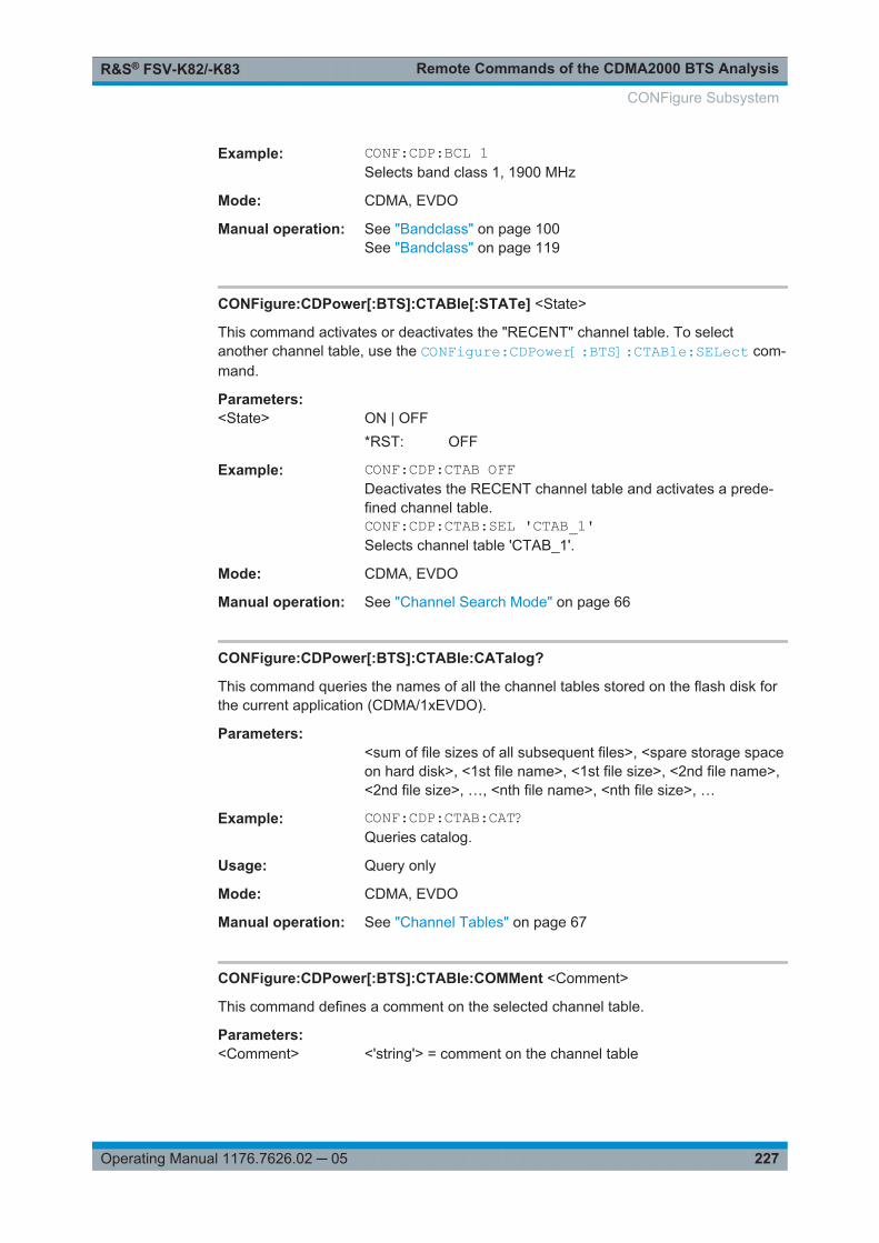
Remote Commands of the CDMA2000 BTS AnalysisR&S® FSV-K82/-K83
227Operating Manual 1176.7626.02 ─ 05
Example: CONF:CDP:BCL 1Selects band class 1, 1900 MHz
Mode: CDMA, EVDO
Manual operation: See "Bandclass" on page 100See "Bandclass" on page 119
CONFigure:CDPower[:BTS]:CTABle[:STATe] <State>
This command activates or deactivates the "RECENT" channel table. To selectanother channel table, use the CONFigure:CDPower[:BTS]:CTABle:SELect com-mand.
Parameters:<State> ON | OFF
*RST: OFF
Example: CONF:CDP:CTAB OFFDeactivates the RECENT channel table and activates a prede-fined channel table.CONF:CDP:CTAB:SEL 'CTAB_1'Selects channel table 'CTAB_1'.
Mode: CDMA, EVDO
Manual operation: See "Channel Search Mode" on page 66
CONFigure:CDPower[:BTS]:CTABle:CATalog?
This command queries the names of all the channel tables stored on the flash disk forthe current application (CDMA/1xEVDO).
Parameters:<sum of file sizes of all subsequent files>, <spare storage spaceon hard disk>, <1st file name>, <1st file size>, <2nd file name>,<2nd file size>, …, <nth file name>, <nth file size>, …
Example: CONF:CDP:CTAB:CAT?Queries catalog.
Usage: Query only
Mode: CDMA, EVDO
Manual operation: See "Channel Tables" on page 67
CONFigure:CDPower[:BTS]:CTABle:COMMent <Comment>
This command defines a comment on the selected channel table.
Parameters:<Comment> <'string'> = comment on the channel table
CONFigure Subsystem

Remote Commands of the CDMA2000 BTS AnalysisR&S® FSV-K82/-K83
228Operating Manual 1176.7626.02 ─ 05
Example: CONF:CDP:CTAB:NAME 'NEW_TAB'Selects channel table for editing. If a channel table with thisname does not exist, a new channel table is created.CONF:CDP:CTAB:DATA0,6,0,0,0,0,1,0.0,10,5,3,4,0,0,1,0.0Defines a table with the following channels: PICH 0.64 and datachannel with RC4/Walsh code 3.32.CONF:CDP:CTAB:COMM 'Comment for NEW_TAB'Specifies 'Comment for NEW_TAB' as comment.
Mode: CDMA, EVDO
CONFigure:CDPower[:BTS]:CTABle:COPY <TargetFileName>
This command copies one channel table to another. Select the channel table you wantto copy using the CONFigure:CDPower[:BTS]:CTABle:SELect command.
Parameters:<TargetFileName> <'string'> = name of the new channel table.
Example: CONF:CDP:CTAB:NAME 'CTAB_1'Selects channel table CTAB_1 for copying.CONF:CDP:CTAB:COPY 'CTAB_2'Copies CTAB_1 to CTAB_2.
Usage: Event
Mode: CDMA, EVDO
CONFigure:CDPower[:BTS]:CTABle:DATA <ChannelType>, <CodeClass>,<CodeNumber>, <Modulation>, <Reserved1>, <Reserved2>, <Status>,<CDPRelative>
This command defines a channel table. The following description applies to EVDOBTS mode (K84) only.
For MS mode, see CONFigure:CDPower[:BTS]:CTABle:DATA on page 229.
Before using this command, you must set the name of the channel table using theCONFigure:CDPower[:BTS]:CTABle:SELect command.
Parameters:<ChannelType> The channel type is numerically coded as follows:
0 = PILOT1 = MAC2 = PREAMBLE with 64 chip length3 = PREAMBLE with 128 chip length4 = PREAMBLE with 256 chip length5 = PREAMBLE with 512 chip length6 = PREAMBLE with 1024 chip length7 = DATA
CONFigure Subsystem
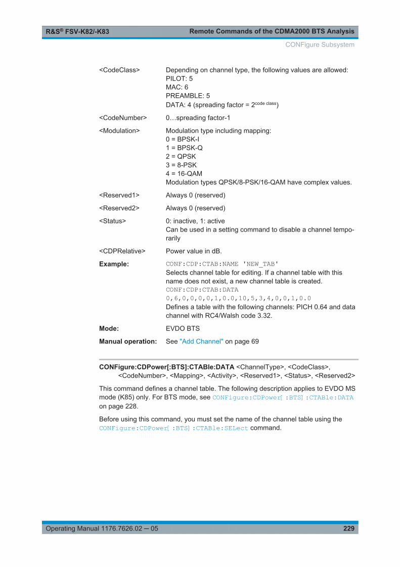
Remote Commands of the CDMA2000 BTS AnalysisR&S® FSV-K82/-K83
229Operating Manual 1176.7626.02 ─ 05
<CodeClass> Depending on channel type, the following values are allowed:PILOT: 5MAC: 6PREAMBLE: 5DATA: 4 (spreading factor = 2code class)
<CodeNumber> 0…spreading factor-1
<Modulation> Modulation type including mapping:0 = BPSK-I1 = BPSK-Q2 = QPSK3 = 8-PSK4 = 16-QAMModulation types QPSK/8-PSK/16-QAM have complex values.
<Reserved1> Always 0 (reserved)
<Reserved2> Always 0 (reserved)
<Status> 0: inactive, 1: activeCan be used in a setting command to disable a channel tempo-rarily
<CDPRelative> Power value in dB.
Example: CONF:CDP:CTAB:NAME 'NEW_TAB'Selects channel table for editing. If a channel table with thisname does not exist, a new channel table is created.CONF:CDP:CTAB:DATA0,6,0,0,0,0,1,0.0,10,5,3,4,0,0,1,0.0Defines a table with the following channels: PICH 0.64 and datachannel with RC4/Walsh code 3.32.
Mode: EVDO BTS
Manual operation: See "Add Channel" on page 69
CONFigure:CDPower[:BTS]:CTABle:DATA <ChannelType>, <CodeClass>,<CodeNumber>, <Mapping>, <Activity>, <Reserved1>, <Status>, <Reserved2>
This command defines a channel table. The following description applies to EVDO MSmode (K85) only. For BTS mode, see CONFigure:CDPower[:BTS]:CTABle:DATAon page 228.
Before using this command, you must set the name of the channel table using theCONFigure:CDPower[:BTS]:CTABle:SELect command.
CONFigure Subsystem

Remote Commands of the CDMA2000 BTS AnalysisR&S® FSV-K82/-K83
230Operating Manual 1176.7626.02 ─ 05
Parameters:<ChannelType> The channel type is numerically coded as follows:
0 = PICH1 = RRI2 = DATA3 = ACK4 = DRC5 = INACTIVE
<CodeClass> 2 to 4
<CodeNumber> 0…15
<Mapping> 0 = I branch1 = Q branch
<Activity> 0..65535 (decimal)The decimal number - interpreted as a binary number in 16 bits -determines the half slot in which the channel is active (value 1)or inactive (value 0). See Table 7-1.
<Reserved1> Always 0 (reserved)
<Status> 0: inactive, 1: activeCan be used in a setting command to disable a channel tempo-rarily
<Reserved2> Always 0 (reserved)
Example: "INST:SEL MDO"'Activate 1xEV–DO MS"CONF:CDP:CTAB:NAME 'NEW_TAB'"'Select table to edit"CONF:CDP:CTAB:DATA 0,4,0,0,65535,0,1,0, 1,4,0,0,43690,0,1,0, 2,2,2,1,65535,0,1,0"'Selects PICH 0.16 on I with full activity, RRI 0.16 on I in eacheven–numbered half slot, and DATA 2.4 on Q with full activity.
Mode: EVDO MS
Table 7-1: Examples for <Activity> parameter settings
Dec. Binary Description
65535 1111 1111 1111 1111 Channel is active in each half slot(e.g.DATA)
43690 1010 1010 1010 1010 Channel is active in half slot 0, 2, 4etc(e.g. RRI)
24576 0110 0000 0000 0000 Channel is active in half slot 1 and 2(e.g.DRC)
CONFigure:CDPower[:BTS]:CTABle:DELete
This command deletes the selected channel table. Select the channel table you wantto delete using the CONFigure:CDPower[:BTS]:CTABle:SELect command.
CONFigure Subsystem

Remote Commands of the CDMA2000 BTS AnalysisR&S® FSV-K82/-K83
231Operating Manual 1176.7626.02 ─ 05
Example: CONF:CDP:CTAB:NAME 'CTAB_1'Selects channel table CTAB_2 for deleting.CONF:CDP:CTAB:DELDeletes channel table CTAB_2.
Usage: Event
Mode: CDMA, EVDO
CONFigure:CDPower[:BTS]:CTABle:NAME <ChannelTable>
This command selects a channel table for editing or creating. To select a command foranalysis, use the CONFigure:CDPower[:BTS]:CTABle:SELect command.
Parameters:<ChanTableName> <'string'> = name of the channel table
Example: CONF:CDP:CTAB:NAME 'NEW_TAB'Selects channel table for editing. If a channel table with thisname does not exist, a new channel table is created.
Mode: CDMA, EVDO
CONFigure:CDPower[:BTS]:CTABle:RESTore
This command restores the predefined channel tables to their factory-set values. In thisway, you can undo unintentional overwriting.
Example: CONF:CDP:CTAB:RESTRestores the channel table.
Usage: Event
Mode: CDMA, EVDO
CONFigure:CDPower[:BTS]:CTABle:SELect <ChannelTable>
This command selects a predefined channel table.
Parameters:<ChanTableName> <'string'> = name of the channel table
*RST: "RECENT"
Mode: CDMA, EVDO
Manual operation: See "Channel Search Mode" on page 66
CONFigure:CDPower[:BTS]:MCARrier [:STATe] <State>
This command activates or deactivates the multi-carrier mode.
CONFigure Subsystem

Remote Commands of the CDMA2000 BTS AnalysisR&S® FSV-K82/-K83
232Operating Manual 1176.7626.02 ─ 05
Parameters:<State> ON | OFF
*RST: OFF
Example: CONF:CDP:MCAR ONActivates the multi-carrier settings.
Mode: CDMA, EVDO
Manual operation: See "Multi Carrier" on page 71
CONFigure:CDPower[:BTS]:MCARrier:FILTer [:STATe] <State>
This command activates or deactivates the usage of a filter for multi-carrier measure-ments.
Parameters:<State> ON | OFF
*RST: OFF
Example: CONF:CDP:MCAR ONActivates multi-carrier modeCONF:CDP:MCAR:FILT OFFActivates an additional filter for multi-carrier measurements
Mode: CDMA, EVDO
Manual operation: See "Multi Carrier Filter" on page 71
CONFigure:CDPower[:BTS]:MCARrier:FILTer:COFRequency <Frequency>
This command sets the cut-off frequency for the RRC filter.
Parameters:<Frequency> Range: 0.1 MHz to 2.4 MHz
*RST: 1.25
Example: CONF:CDP:MCAR ONActivates multi-carrier modeCONF:CDP:MCAR:FILT ONActivates an additional filter for multi-carrier measurementsCONF:CDP:MCAR:FILT:TYPE RRCActivates the RRC filterCONF:CDP:MCAR:FILT:COFR 1.5MHZSets the cut-off frequency to 1.5 MHz
Mode: CDMA, EVDO
Manual operation: See "Cut Off Frequency" on page 72
CONFigure:CDPower[:BTS]:MCARrier:FILTer:ROFF <RollOffFactor>
This command sets the roll-off factor for the RRC filter.
CONFigure Subsystem

Remote Commands of the CDMA2000 BTS AnalysisR&S® FSV-K82/-K83
233Operating Manual 1176.7626.02 ─ 05
Parameters:<RollOffFactor> Range: 0.01 to 0.99
*RST: 0.02
Example: CONF:CDP:MCAR ONActivates multi-carrier modeCONF:CDP:MCAR:FILT ONActivates an additional filter for multi-carrier measurementsCONF:CDP:MCAR:FILT:TYPE RRCActivates the RRC filterCONF:CDP:MCAR:FILT:ROFF 0.05Sets the roll-off factor to 0.05
Mode: CDMA, EVDO
Manual operation: See "Roll-Off Factor" on page 72
CONFigure:CDPower[:BTS]:MCARrier:FILTer:TYPE <Type>
This command sets the filter type to be used in multi-carrier mode.
You can set the parameters for the RRC filter with the CONFigure:CDPower[:BTS]:MCARrier:FILTer:ROFF on page 232 and CONFigure:CDPower[:BTS]:MCARrier:FILTer:COFRequency on page 232 commands.
Parameters:<Type> LPASs | RCC
*RST: LPAS
Example: CONF:CDP:MCAR ONActivates multi-carrier modeCONF:CDP:MCAR:FILT ONActivates an additional filter for multi-carrier measurementsCONF:CDP:MCAR:FILT:TYPE RRCActivates the RRC filter
Mode: CDMA, EVDO
Manual operation: See "Filter Type" on page 71See "Roll-Off Factor" on page 72See "Cut Off Frequency" on page 72
CONFigure:CDPower[:BTS]:MCARrier:MALGo <State>
This command activates or deactivates the enhanced algorithm for the filters in multi-carrier mode.
Parameters:<State> ON | OFF
*RST: ON
CONFigure Subsystem

Remote Commands of the CDMA2000 BTS AnalysisR&S® FSV-K82/-K83
234Operating Manual 1176.7626.02 ─ 05
Example: CONF:CDP:MCAR ONActivates multi-carrier modeCONF:CDP:MCAR:FILT ONActivates an additional filter for multi-carrier measurementsCONF:CDP:MCAR:MALG OFFDeactivates the enhanced algorithm
Mode: CDMA, EVDO
Manual operation: See "Enhanced Algorithm" on page 71
CONFigure:CDPower[:BTS]:MEASurement <Measurement>
This command selects the measurement type.
Parameters:<Measurement> ACLR | CCDF | CDPower | ESPectrum | OBWidth | POWer
ACLRAdjacent-Channel Power measurement(with predefined settings according to the CDMA2000 standard)CCDFmeasurement of the complementary cumulative distributionfunction (signal statistics)CDPowerCode Domain Analyzer measurement.ESPectrumcheck of signal power (Spectrum Emission Mask)OBWidthmeasurement of the occupied bandwidthPOWerSignal Channel Power measurement(with predefined settings according to the CDMA2000 standard)*RST: CDPower
Example: CONF:CDP:MEAS POWSelects Signal Channel Power measurement.
Mode: CDMA, EVDO
Manual operation: See "Code Domain Analyzer" on page 100See "Power" on page 100See "Ch Power ACLR" on page 100See "Spectrum Emission Mask" on page 110See "Occupied Bandwidth" on page 120See "CCDF" on page 121
CONFigure Subsystem

Remote Commands of the CDMA2000 BTS AnalysisR&S® FSV-K82/-K83
235Operating Manual 1176.7626.02 ─ 05
7.4 DISPlay Subsystem
The DISPLay subsystem controls the selection and presentation of textual and graphicinformation as well as of measurement data on the display.
DISPlay:MTABle............................................................................................................ 235DISPlay[:WINDow<n>]:SIZE........................................................................................... 235DISPlay[:WINDow<n>]:SSELect......................................................................................236DISPlay[:WINDow<n>]:STATe.........................................................................................236DISPlay[:WINDow<n>]:TRACe<t>:MODE.........................................................................236DISPlay[:WINDow<n>]:TRACe<t>[:STATe].......................................................................237DISPlay[:WINDow<n>]:TRACe<t>:Y[:SCALe]................................................................... 238DISPlay[:WINDow<n>]:TRACe<t>:Y[:SCALe]:AUTO......................................................... 238DISPlay[:WINDow<n>]:TRACe<t>:Y[:SCALe]:MODE.........................................................239DISPlay[:WINDow<n>]:TRACe<t>:Y[:SCALe]:PDIVision.................................................... 239DISPlay[:WINDow<n>]:TRACe<t>:Y[:SCALe]:RLEVel....................................................... 239DISPlay[:WINDow<n>]:TRACe<t>:Y[:SCALe]:RLEVel:OFFSet........................................... 240DISPlay[:WINDow<n>]:TRACe<t>:Y[:SCALe]:RPOSition................................................... 240DISPlay[:WINDow<n>]:TRACe<t>:Y[:SCALe]:RVALue...................................................... 241DISPlay[:WINDow<n>]:TRACe<t>:Y:SPACing.................................................................. 241DISPlay[:WINDow<n>]:TRACe<t>:Y[:SCALe]:MAXimum................................................... 241DISPlay[:WINDow<n>]:TRACe<t>:Y[:SCALe]:MINimum.....................................................242
DISPlay:MTABle <DisplayMode>
This command turns the marker table on and off.
Parameters:<DisplayMode> ON
Marker table is displayed.OFFMarker table is not displayed.AUTOMarker table is only displayed if 2 or more markers are active.*RST: AUTO
Example: To activate the table display:DISP:MTAB ONTo query the current state of the marker table display:DISP:MTAB?
Manual operation: See "Marker Table" on page 148
DISPlay[:WINDow<n>]:SIZE <Size>
This command enlargens the measurement window indicated by the suffix to fullscreen. The result display of the screen is, by default, the same as that of the first mea-surement screen.
DISPlay Subsystem

Remote Commands of the CDMA2000 BTS AnalysisR&S® FSV-K82/-K83
236Operating Manual 1176.7626.02 ─ 05
Suffix: <n>
.window; For applications that do not have more than 1 measure-ment window, the suffix <n> is irrelevant.
Parameters:<Size> SMALl | LARGe
*RST: SMALl
Example: DISP:WIND2:SIZE LARGMaximizes the second measurement screen
Mode: CDMA, EVDO
DISPlay[:WINDow<n>]:SSELect
This command selects which window (screen) is active.
Suffix: <n>
.1...4window; For applications that do not have more than 1 measure-ment window, the suffix <n> is irrelevant.
Parameters:*RST: 1
Example: DISP:WIND1:SSELSets the window 1 active.
Mode: CDMA, EVDO
DISPlay[:WINDow<n>]:STATe <State>
Activates/deactivates the window specified by the suffix <n>. The other measurementsare not aborted but continue running in the background:
Suffix: <n>
.window
Parameters:<State> ON | OFF
*RST: OFF
Example: DISP:WIND3:STAT ONTurns on a third measurement screen.
Mode: CDMA, EVDO, TDS, WCDMA
DISPlay[:WINDow<n>]:TRACe<t>:MODE <Mode>
This command defines the type of display and the evaluation of the traces. WRITE cor-responds to the Clr/Write mode of manual operation. The trace is switched off (=BLANK in manual operation) with DISPlay[:WINDow<n>]:TRACe<t>[:STATe].
DISPlay Subsystem

Remote Commands of the CDMA2000 BTS AnalysisR&S® FSV-K82/-K83
237Operating Manual 1176.7626.02 ─ 05
The number of measurements for AVERage, MAXHold and MINHold is defined withthe [SENSe:]AVERage<n>:COUNt or [SENSe:]SWEep:COUNt commands. It shouldbe noted that synchronization to the end of the indicated number of measurements isonly possible in single sweep mode.
Suffix: <n>
.window; For applications that do not have more than 1 measure-ment window, the suffix <n> is irrelevant.
<t> trace
Parameters:<Mode> WRITe | VIEW | AVERage | MAXHold | MINHold | BLANk
*RST: WRITe for TRACe1, STATe OFF forTRACe2/3/4/5/6
For details on trace modes refer to Chapter 6.4.4, "Trace ModeOverview", on page 157.
Example: INIT:CONT OFFSwitching to single sweep mode.SWE:COUN 16Sets the number of measurements to 16.DISP:TRAC3:MODE MAXHSwitches on the calculation of the maximum peak for trace 3.INIT;*WAIStarts the measurement and waits for the end of the 16 sweeps.
Manual operation: See "Clear Write" on page 87See "Max Hold" on page 87See "Min Hold" on page 87See "Average" on page 87See "View" on page 88
DISPlay[:WINDow<n>]:TRACe<t>[:STATe] <State>
This command switches on or off the display of the corresponding trace. The othermeasurements are not aborted but continue running in the background.
Suffix: <n>
.window; For applications that do not have more than 1 measure-ment window, the suffix <n> is irrelevant.
<t> trace
Parameters:<State> ON | OFF
*RST: ON for TRACe1, OFF for TRACe2 to 6
Example: DISP:TRAC3 ONManual operation: See "Blank" on page 159
DISPlay Subsystem

Remote Commands of the CDMA2000 BTS AnalysisR&S® FSV-K82/-K83
238Operating Manual 1176.7626.02 ─ 05
DISPlay[:WINDow<n>]:TRACe<t>:Y[:SCALe] <Range>
This command defines the display range of the y-axis with logarithmic scaling.
The command works only for a logarithmic scaling. You can select the scaling withDISPlay[:WINDow<n>]:TRACe<t>:Y:SPACing on page 241.
Suffix: <n>
.window; For applications that do not have more than 1 measure-ment window, the suffix <n> is irrelevant.
<t> irrelevant
Parameters:<Range> Range: 10 to 200
*RST: 100Default unit: dB
Example: DISP:TRAC:Y 110dBManual operation: See "Range Log 100 dB" on page 122
See "Range Log 50 dB" on page 123See "Range Log 10 dB" on page 123See "Range Log 5 dB" on page 123See "Range Log 1 dB" on page 123See "Range Log Manual" on page 123
DISPlay[:WINDow<n>]:TRACe<t>:Y[:SCALe]:AUTO <Mode>
This command turns automatic scaling of the y-axis on and off.
If on, the R&S FSV/FSVA determines the ideal scale of the y-axis for the current mea-surement results.
Suffix: <n>
.window; For applications that do not have more than 1 measure-ment window, the suffix <n> is irrelevant.
<t> only 1trace
Parameters:<Mode> ON
Automatic scaling is on.OFFAutomatic scaling is off.ONCEAutomatic scaling is performed once.*RST: OFF
Example: DISP:WIND2:TRAC:Y:SCAL:AUTO ONCEActivates automatic scaling of the Y-axis for the active trace
Mode: CDMA, EVDO, OFDM, OFDMA/WiBro, PHN
DISPlay Subsystem

Remote Commands of the CDMA2000 BTS AnalysisR&S® FSV-K82/-K83
239Operating Manual 1176.7626.02 ─ 05
Manual operation: See "Auto Scale Once" on page 81
DISPlay[:WINDow<n>]:TRACe<t>:Y[:SCALe]:MODE <Mode>
This command selects the type of scaling of the y-axis.
When SYSTem:DISPlay:UPDate is turned off, this command has no immediateeffect on the screen.
Suffix: <n>
.window; For applications that do not have more than 1 measure-ment window, the suffix <n> is irrelevant.
<t> irrelevant
Parameters:<Mode> ABSolute
absolute scaling of the y-axisRELativerelative scaling of the y-axis*RST: ABS
Example: DISP:TRAC:Y:MODE RELManual operation: See "Grid Abs/Rel " on page 135
DISPlay[:WINDow<n>]:TRACe<t>:Y[:SCALe]:PDIVision <Value>
This remote command determines the grid spacing on the Y axis for all diagrams,where possible.
Suffix: <n>
.irrelevant
<t> irrelevant
Parameters:<Value> numeric value; the unit depends on the result display
*RST: depends on the result display
Example: DISP:TRAC:Y:PDIV 10Sets the grid spacing to 10 units (for example 10 dB in the CodeDomain Power result display).
Mode: CDMA, BT, EVDO, TDS, WCDMA
DISPlay[:WINDow<n>]:TRACe<t>:Y[:SCALe]:RLEVel <ReferenceLevel>
This command defines the reference level.
With the reference level offset ≠ 0, the value range of the reference level is modified bythe offset.
DISPlay Subsystem

Remote Commands of the CDMA2000 BTS AnalysisR&S® FSV-K82/-K83
240Operating Manual 1176.7626.02 ─ 05
Suffix: <n>
.irrelevant.
<t> irrelevant
Parameters:<ReferenceLevel> The unit is variable.
Range: see datasheet*RST: -10dBm
Example: DISP:TRAC:Y:RLEV -60dBmManual operation: See "Ref Level" on page 62
DISPlay[:WINDow<n>]:TRACe<t>:Y[:SCALe]:RLEVel:OFFSet <Value>
This command defines a reference level offset.
Suffix: <n>
.irrelevant.
<t> irrelevant
Parameters:<Value> Range: -200 to 200
*RST: 0Default unit: dB
Example: DISP:TRAC:Y:RLEV:OFFS -10dBManual operation: See "Ref Level Offset" on page 63
DISPlay[:WINDow<n>]:TRACe<t>:Y[:SCALe]:RPOSition <Position>
This command defines the position of the reference level on the display grid..
When using a tracking generator (only with option R&S FSV-B9 or -B10, requiresactive normalization), and in Bluetooth mode (option R&S FSV-K8) this commanddefines the position of the reference value for all windows.
Suffix: <n>
.Selects the measurement window.
<t> irrelevant
Parameters:<Position> 0 PCT corresponds to the lower display border, 100% corre-
sponds to the upper display border.Range: 0 to 100*RST: Spectrum mode: 100 PCT, with tracking generator
or time display: 50 PCTDefault unit: PCT
Example: DISP:TRAC:Y:RPOS 50PCTManual operation: See "Ref Level Position" on page 135
DISPlay Subsystem

Remote Commands of the CDMA2000 BTS AnalysisR&S® FSV-K82/-K83
241Operating Manual 1176.7626.02 ─ 05
DISPlay[:WINDow<n>]:TRACe<t>:Y[:SCALe]:RVALue <Value>
The command defines the power value assigned to the reference position in the grid.
When using a tracking generator, this command requires active normalization.
Suffix: <n>
.irrelevant
<t> irrelevant
Parameters:<Value> *RST: 0 dB, coupled to reference level
Example: DISP:TRAC:Y:RVAL -20dBmDefines a reference position of -20 dBm.
DISPlay[:WINDow<n>]:TRACe<t>:Y:SPACing <ScalingType>
This command selects the scaling of the y-axis.
Suffix: <n>
.Selects the measurement window.
<t> irrelevant
Parameters:<ScalingType> LOGarithmic
Logarithmic scaling.LINearLinear scaling in %.LDBLinear scaling in dB.*RST: LOGarithmic
Example: DISP:TRAC:Y:SPAC LINSelect a linear scale.
Manual operation: See "Range Log 100 dB" on page 122See "Range Log 50 dB" on page 123See "Range Log 10 dB" on page 123See "Range Log 5 dB" on page 123See "Range Log 1 dB" on page 123See "Range Log Manual" on page 123See "Range Linear %" on page 124See "Range Lin. Unit" on page 124
DISPlay[:WINDow<n>]:TRACe<t>:Y[:SCALe]:MAXimum <Value>
This command defines the maximum value of the y-axis for the selected result display.
Suffix: <n>
.window; For applications that do not have more than 1 measure-ment window, the suffix <n> is irrelevant.
DISPlay Subsystem

Remote Commands of the CDMA2000 BTS AnalysisR&S® FSV-K82/-K83
242Operating Manual 1176.7626.02 ─ 05
<t> irrelevant
Parameters:<Value> <numeric value>
*RST: depends on the result displayThe unit and range depend on the result display.
Example: DISP:TRAC:Y:MIN -60DISP:TRAC:Y:MAX 0Defines the y-axis with a minimum value of -60 and maximumvalue of 0.
Mode: CDMA, EVDO
Manual operation: See "Y-Axis Maximum" on page 81
DISPlay[:WINDow<n>]:TRACe<t>:Y[:SCALe]:MINimum <Value>
This command defines the minimum value of the y-axis for the selected result display.
Suffix: <n>
.window; For applications that do not have more than 1 measure-ment window, the suffix <n> is irrelevant.
<t> irrelevant
Parameters:<Value> <numeric value>
*RST: depends on the result displayThe unit and range depend on the result display.
Example: DISP:TRAC:Y:MIN -60DISP:TRAC:Y:MAX 0Defines the y-axis with a minimum value of -60 and maximumvalue of 0.
Mode: CDMA, EVDO
Manual operation: See "Y-Axis Minimum" on page 82
7.5 INSTrument Subsystem
The INSTrument subsystem selects the operating mode of the unit either via textparameters or fixed numbers.
INSTrument[:SELect]......................................................................................................243INSTrument:NSELect..................................................................................................... 243
INSTrument Subsystem

Remote Commands of the CDMA2000 BTS AnalysisR&S® FSV-K82/-K83
243Operating Manual 1176.7626.02 ─ 05
INSTrument[:SELect] <Mode>
Parameters:<Mode> BC2K
This command switches to the CDMA2000 BTS Analysis mode(R&S FSV-K82 option)
INSTrument:NSELect <Mode>
Parameters:<Mode> 10
This command switches to the CDMA2000 BTS Analysis mode(R&S FSV-K82 option)
7.6 SENSe Subsystem
The SENSe subsystem controls the essential parameters of the analyzer. In accord-ance with the SCPI standard, the keyword SENSe is optional, which means that it is notnecessary to include the SENSe node in command sequences.
Note that most commands in the SENSe subsystem are identical to the base unit; onlythe commands specific to this option are described here.
7.6.1 SENSe:CDPower Subsystem..................................................................................... 243
7.6.2 Other SENSe Commands Referenced in this Manual................................................ 252
7.6.2.1 SENSe:ADJust Subsystem......................................................................................... 252
7.6.2.2 SENSe:ESPectrum Subsystem.................................................................................. 254
7.6.2.3 SENSe:BANDwidth subsystem...................................................................................266
7.6.2.4 SENSe:FREQuency subsystem..................................................................................270
7.6.2.5 SENSe:POWer subsystem......................................................................................... 273
7.6.2.6 SENSe:SWEep subsystem......................................................................................... 283
7.6.2.7 Other Commands in the SENSe Subsystem.............................................................. 289
7.6.1 SENSe:CDPower Subsystem
This subsystem sets the parameters for the code domain measurements mode.
[SENSe:]CDPower:ANTenna.......................................................................................... 244[SENSe:]CDPower:CODE...............................................................................................244[SENSe:]CDPower:ICThreshold.......................................................................................245[SENSe:]CDPower:IQLength...........................................................................................245[SENSe:]CDPower:LEVel:ADJust.................................................................................... 245[SENSe:]CDPower:MAPPing...........................................................................................245
SENSe Subsystem

Remote Commands of the CDMA2000 BTS AnalysisR&S® FSV-K82/-K83
244Operating Manual 1176.7626.02 ─ 05
[SENSe:]CDPower:LCODe:MASK................................................................................... 246[SENSe:]CDPower:LCODe:OFFSet ................................................................................ 246[SENSe:]CDPower:LCODe:MODE ..................................................................................247[SENSe:]CDPower:NORMalize........................................................................................247[SENSe:]CDPower:ORDer.............................................................................................. 247[SENSe:]CDPower:OVERview.........................................................................................248[SENSe:]CDPower:PNOFfset..........................................................................................248[SENSe:]CDPower:PPReference.....................................................................................249[SENSe:]CDPower:PREFerence......................................................................................249[SENSe:]CDPower:QINVert............................................................................................ 249[SENSe:]CDPower:SBANd..............................................................................................250[SENSe:]CDPower:SET:COUNt.......................................................................................250[SENSe:]CDPower:SET..................................................................................................250[SENSe:]CDPower:SFACtor............................................................................................250[SENSe:]CDPower:SLOT................................................................................................251[SENSe:]CDPower:TPMeas............................................................................................ 251
[SENSe:]CDPower:ANTenna <AntennaState>
This command deactivates the orthogonal transmit diversity (two-antenna system) ordefines the antenna for which the result display evaluated.
Parameters:<AntennaState> OFF | 1 | 2
OFFThe aggregate signal from both antennas is fed in.1The signal of antenna 1 is fed in.2The signal of antenna 2 is fed in.*RST: OFFFor further details refer to "Antenna Diversity" on page 72.
Example: CDP:ANT 2Selects antenna 2.
Mode: CDMA
Manual operation: See "Antenna Diversity" on page 72
[SENSe:]CDPower:CODE <CodeNo>
This command selects the code number.
For further details refer to "Channel (Code) Number" on page 75.
Parameters:<CodeNo> <numeric value>
Range: 0 to base spreading factor - 1Increment: 1*RST: 0
SENSe Subsystem

Remote Commands of the CDMA2000 BTS AnalysisR&S® FSV-K82/-K83
245Operating Manual 1176.7626.02 ─ 05
Example: CDP:CODE 8Selects the eighth channel.
Mode: CDMA
Manual operation: See "Channel (Code) Number" on page 75See "Select" on page 79
[SENSe:]CDPower:ICThreshold <ThresholdLevel>
This command defines the minimum power that a single channel must have comparedto the total signal in order to be regarded as an active channel. Channels below thespecified threshold are regarded as "inactive".
Parameters:<ThresholdLevel> Range: -100 dB to 0 dB
*RST: -60 dB
Example: CDP:ICT -50Sets the Inactice Channel Threshold to -50 dB.
Mode: CDMA, EVDO, TDS, WCDMA
Manual operation: See "Inactive Channel Threshold" on page 66
[SENSe:]CDPower:IQLength <CaptureLength>
This command sets the capture length in multiples of the power control group.
Parameters:<CaptureLength> Range: 2 to 64
*RST: 3
Example: SENS:CDP:IQLength 3Mode: CDMA
Manual operation: See "Capture Length" on page 64
[SENSe:]CDPower:LEVel:ADJust
This command adjusts the reference level to the measured channel power. Thisensures that the settings of the RF attenuation and the reference level are optimallyadjusted to the signal level without overloading the R&S FSV/FSVA or limiting thedynamic range by an S/N ratio that is too small.
Example: CDP:LEV:ADJAdjusts the reference level.
Mode: CDMA, EVDO, TDS, WCDMA
[SENSe:]CDPower:MAPPing <SignalComponent>
This command switches between I and Q component of the signal.
SENSe Subsystem

Remote Commands of the CDMA2000 BTS AnalysisR&S® FSV-K82/-K83
246Operating Manual 1176.7626.02 ─ 05
Parameters:<SignalComponent> I | Q
*RST: Q
Example: CDP:MAPP QMode: CDMA, WCDMA
Manual operation: See "Select" on page 79
[SENSe:]CDPower:LCODe:MASK <Mask>
Defines the long code mask of the mobile in hexadecimal form.
Note: For the default mask value of 0 the long code offset (see ) is not taken into con-sideration.
Parameters:<Mask> Range: #H0 to #H4FFFFFFFFFF
*RST: #H0
Example: INST:SEL MC2K'Activate cdma2000 MS; by default, "CDP relative" is displayedin screen A and "Result Summary" in screen B.INIT:CONT OFF'Select single sweepTRIG:SOUR:EXT'Select external trigger sourceCDP:LCOD:MASK '#HF''Define long code maskINIT;*WAI'Start measurement with synchronization
Mode: CDMA
Manual operation: See "Long Code Mask" on page 74
[SENSe:]CDPower:LCODe:OFFSet <CodeOffset>
Defines the long code offset, including the PN offset. This offset is applied at the nexttrigger pulse (which cannot occur until a setup time of 300 ms has elapsed).
This command is ignored if [SENSe:]CDPower:LCODe:MASK is set to 0.
Parameters:<CodeOffset> Offset in chips in hexadecimal format with a 52-bit resolu-
tion. The chips offset is calculated as follows: tSinceS-tartGPS * 1.2288 MChips/s, where tSinceStartGPS is definedin seconds.This value corresponds to the GPS timing since 6.1.198000:00:00 UTC.*RST: #H0
SENSe Subsystem
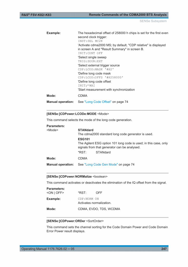
Remote Commands of the CDMA2000 BTS AnalysisR&S® FSV-K82/-K83
247Operating Manual 1176.7626.02 ─ 05
Example: The hexadecimal offset of 258000 h chips is set for the first evensecond clock trigger:INST:SEL MC2K'Activate cdma2000 MS; by default, "CDP relative" is displayedin screen A and "Result Summary" in screen B.INIT:CONT OFF'Select single sweepTRIG:SOUR:EXT'Select external trigger sourceCDP:LCOD:MASK '#H2''Define long code maskCDP:LCOD:OFFS '#H258000''Define long code offsetINIT;*WAI'Start measurement with synchronization
Mode: CDMA
Manual operation: See "Long Code Offset" on page 74
[SENSe:]CDPower:LCODe:MODE <Mode>
This command selects the mode of the long code generation.
Parameters:<Mode> STANdard
The cdma2000 standard long code generator is used.ESG101The Agilent ESG option 101 long code is used; in this case, onlysignals from that generator can be analysed.*RST: STANdard
Mode: CDMA
Manual operation: See "Long Code Gen Mode" on page 74
[SENSe:]CDPower:NORMalize <boolean>
This command activates or deactivates the elimination of the IQ offset from the signal.
Parameters:<ON | OFF> *RST: OFF
Example: CDP:NORM ONActivates normalization.
Mode: CDMA, EVDO, TDS, WCDMA
[SENSe:]CDPower:ORDer <SortOrder>
This command sets the channel sorting for the Code Domain Power and Code DomainError Power result displays.
SENSe Subsystem

Remote Commands of the CDMA2000 BTS AnalysisR&S® FSV-K82/-K83
248Operating Manual 1176.7626.02 ─ 05
Parameters:<SortOrder> HADamard | BITReverse
*RST: HADamardFor further details refer to "Code Order" on page 76.
Example: CDP:ORD HADSets Hadamard order.TRAC? TRACE2Reads out the results in Hadamard order.CDP:ORD BITRSets BitReverse order.TRAC? TRACE2Reads out the results in BitReverse order.
Mode: CDMA
Manual operation: See "Code Order" on page 76
[SENSe:]CDPower:OVERview <State>
This command switches to an overview display of a code domain measurement (CDPrel./CDP abs./ CDEP). If enabled, the I branch of the code power is displayed in screenA and the Q branch in screen B. Both results can be read using TRACE:DATA?TRACE1 and TRACE:DATA? TRACE2; respectively. If disabled, screen A displays the Ibranch and screen B provides the result summary display.
Parameters:<State> ON | OFF
*RST: OFF
Example: CDP:OVER OFFMode: CDMA, EVDO, WCDMA
Manual operation: See "Code Domain Overview (MS mode only)" on page 77
[SENSe:]CDPower:PNOFfset <Offset>
This command sets the PN offset of the base station in multiples of 64 chips.
Parameters:<Offset> Range: 0 to 511
*RST: 0
Example: CDP:PNOF 45Sets PN offset.
Mode: CDMA
Manual operation: See "PN Offset" on page 71
SENSe Subsystem

Remote Commands of the CDMA2000 BTS AnalysisR&S® FSV-K82/-K83
249Operating Manual 1176.7626.02 ─ 05
[SENSe:]CDPower:PPReference <Mode>
This command defines how the pilot channel power is displayed in the absolute sum-mary. In relative mode, the reference power is the total power.
Parameters:<Mode> ABS | REL
*RST: ABS
Example: CDP:PPR RELPilot channel power is displayed in relation to the total power.
Mode: CDMA
Manual operation: See "Pilot Power (MS mode only)" on page 76
[SENSe:]CDPower:PREFerence <Power>
This command specifies the reference power for the relative power result displays (e.g.Code Domain Power, Power vs PCG).
Parameters:<Power> PICH | TOTal
PICHThe reference power is the power of the pilot channel. Whichpilot channel is used as reference depends on the antennadiversity (for details see [SENSe:]CDPower:ANTennaon page 244 command).TOTalThe reference power is the total power of the signal referred perPCG to the corresponding PCG.*RST: PICHFor further information refer to "Power Reference" on page 76
Example: CDP:PREF TOTSets total power as reference power.
Mode: CDMA
Manual operation: See "Power Reference" on page 76
[SENSe:]CDPower:QINVert <State>
This command inverts the Q component of the signal.
Parameters:ON | OFF *RST: OFF
Example: CDP:QINV ONActivates inversion of Q component.
Mode: CDMA, EVDO, TDS, WCDMA
Manual operation: See "Invert Q" on page 63
SENSe Subsystem

Remote Commands of the CDMA2000 BTS AnalysisR&S® FSV-K82/-K83
250Operating Manual 1176.7626.02 ─ 05
[SENSe:]CDPower:SBANd <NORMal | INVers>
This command is used to swap the left and right sideband.
Parameters:<NORMal | INVers> *RST: NORM
Example: CDP:SBAN INVSwitches the right and left sideband.
Mode: CDMA, EVDO, TDS
[SENSe:]CDPower:SET:COUNt <NoOfSets>
This command sets the number of sets to be captured and stored in the instrument'smemory.
Refer to "Set Count" on page 64 for more information.
Parameters:<NoOfSets> Range: 1 to TDS: 99; CDMA: 490
Increment: 1*RST: 1
Example: CDP:SET:COUN 12Sets the number of sets to 12.
Mode: TDS
Manual operation: See "Set Count" on page 64
[SENSe:]CDPower:SET <SetNo>
This command selects a specific set for further analysis. The number of sets has to bedefined with the [SENSe:]CDPower:SET command before using this command.
Parameters:<SetNo> Range: 0 to SET COUNT -1
Increment: 1*RST: 0
Example: CDP:SET:COUN 10Selects the 10th set for further analysis.
Mode: CDMA, EVDO, TDS
Manual operation: See "Set to Analyze" on page 64
[SENSe:]CDPower:SFACtor <SpreadingFactor>
This command defines the base spreading factor. If the base spreading factor of 64 isused for channels with a spreading factor of 128 (code class 7), an alias power is dis-played in the Code Domain Power and Code Domain Error Power diagrams.
SENSe Subsystem

Remote Commands of the CDMA2000 BTS AnalysisR&S® FSV-K82/-K83
251Operating Manual 1176.7626.02 ─ 05
Parameters:<SpreadingFactor> 64 | 128
*RST: 64
Example: CDP:SFAC 128Selects base spreading factor 128.
Mode: CDMA
Manual operation: See "Base Spreading Factor" on page 70See "Base Spreading Factor" on page 73
[SENSe:]CDPower:SLOT <numeric value>
This command selects the slot/Power Control Group (PCG) to be analyzed.
Parameters:<numeric value> Range: 0 to TDS: 62; CDMA: (capture length-1); WCDMA.
14Increment: 1*RST: 0The capture length is defined via the [SENSe:]CDPower:IQLength on page 245 command.
Example: CDP:SLOT 7Selects slot number 7 for analysis.
Mode: CDMA, EVDO, TDS, WCDMA
Manual operation: See "Power Control Group" on page 75See "Select" on page 79
[SENSe:]CDPower:TPMeas <State>
This command actives or deactivates the timing and phase offset evaluation of thechannels to the pilot.
The results are queried using the TRACe<n>[:DATA]? on page 292 command andthe CALCulate<1…4>:MARKer<1…4>:FUNCtion:CDPower[:BTS]:RESult? com-mand.
Parameters:<State> ON | OFF
*RST: OFF
SENSe Subsystem

Remote Commands of the CDMA2000 BTS AnalysisR&S® FSV-K82/-K83
252Operating Manual 1176.7626.02 ─ 05
Example: CDP:TPM ONActivates timing and phase offset.CDP:SLOT 2Selects power control group 2.CDP:CODE 11Selects code number 11.CALC:MARK:FUNC:CDP:RES? TOFFReads out timing offset of the code with number 11 in PCG 2.CALC:MARK:FUNC:CDP:RES? POFFReads out the phase offset of the code with number 11 in PCG2.
Mode: CDMA
Manual operation: See "Time/Phase Estimation" on page 77See "Normalize" on page 77
7.6.2 Other SENSe Commands Referenced in this Manual
7.6.2.1 SENSe:ADJust Subsystem
[SENSe:]ADJust:ALL......................................................................................................252[SENSe:]ADJust:CONFiguration:HYSTeresis:LOWer.........................................................252[SENSe:]ADJust:CONFiguration:HYSTeresis:UPPer......................................................... 253[SENSe:]ADJust:CONFigure:LEVel:DURation...................................................................253[SENSe:]ADJust:CONFigure:LEVel:DURation:MODE........................................................ 253[SENSe:]ADJust:FREQuency..........................................................................................254[SENSe:]ADJust:LEVel...................................................................................................254
[SENSe:]ADJust:ALL
This command determines the ideal frequency and level configuration for the currentmeasurement.
Example: ADJ:ALLManual operation: See "Auto All" on page 92
[SENSe:]ADJust:CONFiguration:HYSTeresis:LOWer <Threshold>
This command defines a lower threshold the signal must drop below before the refer-ence level is automatically adjusted when the "Auto Level" function is performed.
For more information see [SENSe:]ADJust:LEVel).
Parameters:<Threshold> Range: 0 to 200
*RST: +1 dBDefault unit: dB
SENSe Subsystem

Remote Commands of the CDMA2000 BTS AnalysisR&S® FSV-K82/-K83
253Operating Manual 1176.7626.02 ─ 05
Example: SENS:ADJ:CONF:HYST:LOW 2Example: For an input signal level of currently 20 dBm, the reference level
will only be adjusted when the signal level falls below 18 dBm.
Manual operation: See "Lower Level Hysteresis" on page 93
[SENSe:]ADJust:CONFiguration:HYSTeresis:UPPer <Threshold>
This command defines an upper threshold the signal must exceed before the referencelevel is automatically adjusted when the "Auto Level" function is performed.
For more information see [SENSe:]ADJust:LEVel).
Parameters:<Threshold> Range: 0 to 200
*RST: +1 dBDefault unit: dB
Example: SENS:ADJ:CONF:HYST:UPP 2For an input signal level of currently 20 dBm, the reference levelwill only be adjusted when the signal level rises above 22 dBm.
Manual operation: See "Upper Level Hysteresis" on page 93
[SENSe:]ADJust:CONFigure:LEVel:DURation <Duration>
This command defines the duration of the level measurement used to determine theoptimal reference level automatically (for SENS:ADJ:LEV ON).
Parameters:<Duration> <numeric value> in seconds
Range: 0.001 to 16000.0*RST: 0.001Default unit: s
Example: ADJ:CONF:LEV:DUR:5Manual operation: See "Meas Time Manual" on page 92
[SENSe:]ADJust:CONFigure:LEVel:DURation:MODE <Mode>
This command selects the way the R&S FSV/FSVA determines the length of the mea-surement that is performed while determining the ideal reference level.
Parameters:<Mode> AUTO
Automatically determines the measurement length.MANualManual definition of the measurement length.*RST: AUTO
SENSe Subsystem
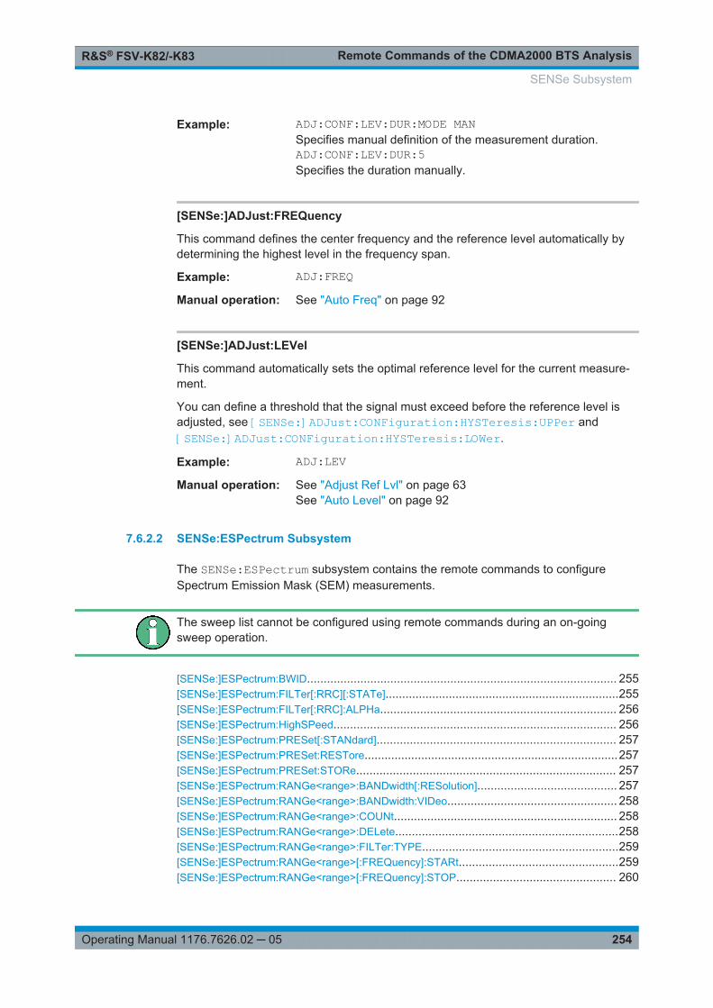
Remote Commands of the CDMA2000 BTS AnalysisR&S® FSV-K82/-K83
254Operating Manual 1176.7626.02 ─ 05
Example: ADJ:CONF:LEV:DUR:MODE MANSpecifies manual definition of the measurement duration.ADJ:CONF:LEV:DUR:5Specifies the duration manually.
[SENSe:]ADJust:FREQuency
This command defines the center frequency and the reference level automatically bydetermining the highest level in the frequency span.
Example: ADJ:FREQManual operation: See "Auto Freq" on page 92
[SENSe:]ADJust:LEVel
This command automatically sets the optimal reference level for the current measure-ment.
You can define a threshold that the signal must exceed before the reference level isadjusted, see [SENSe:]ADJust:CONFiguration:HYSTeresis:UPPer and[SENSe:]ADJust:CONFiguration:HYSTeresis:LOWer.
Example: ADJ:LEVManual operation: See "Adjust Ref Lvl" on page 63
See "Auto Level" on page 92
7.6.2.2 SENSe:ESPectrum Subsystem
The SENSe:ESPectrum subsystem contains the remote commands to configureSpectrum Emission Mask (SEM) measurements.
The sweep list cannot be configured using remote commands during an on-goingsweep operation.
[SENSe:]ESPectrum:BWID............................................................................................. 255[SENSe:]ESPectrum:FILTer[:RRC][:STATe]......................................................................255[SENSe:]ESPectrum:FILTer[:RRC]:ALPHa....................................................................... 256[SENSe:]ESPectrum:HighSPeed..................................................................................... 256[SENSe:]ESPectrum:PRESet[:STANdard]........................................................................ 257[SENSe:]ESPectrum:PRESet:RESTore............................................................................257[SENSe:]ESPectrum:PRESet:STORe.............................................................................. 257[SENSe:]ESPectrum:RANGe<range>:BANDwidth[:RESolution].......................................... 257[SENSe:]ESPectrum:RANGe<range>:BANDwidth:VIDeo................................................... 258[SENSe:]ESPectrum:RANGe<range>:COUNt................................................................... 258[SENSe:]ESPectrum:RANGe<range>:DELete...................................................................258[SENSe:]ESPectrum:RANGe<range>:FILTer:TYPE...........................................................259[SENSe:]ESPectrum:RANGe<range>[:FREQuency]:STARt................................................259[SENSe:]ESPectrum:RANGe<range>[:FREQuency]:STOP................................................ 260
SENSe Subsystem
Remote Commands of the CDMA2000 BTS AnalysisR&S® FSV-K82/-K83
255Operating Manual 1176.7626.02 ─ 05
[SENSe:]ESPectrum:RANGe<range>:INPut:ATTenuation..................................................260[SENSe:]ESPectrum:RANGe<range>:INPut:ATTenuation:AUTO........................................ 261[SENSe:]ESPectrum:RANGe<range>:INPut:GAIN:STATe..................................................261[SENSe:]ESPectrum:RANGe<range>:INSert.................................................................... 261[SENSe:]ESPectrum:RANGe<range>:LIMit<source>:ABSolute:STARt................................ 262[SENSe:]ESPectrum:RANGe<range>:LIMit<source>:ABSolute:STOP.................................262[SENSe:]ESPectrum:RANGe<range>:LIMit<source>:RELative:STARt.................................263[SENSe:]ESPectrum:RANGe<range>:LIMit<source>:RELative:STOP................................. 263[SENSe:]ESPectrum:RANGe<range>:LIMit<source>:STATe.............................................. 263[SENSe:]ESPectrum:RANGe<range>:RLEVel...................................................................264[SENSe:]ESPectrum:RANGe<range>:SWEep:TIME..........................................................264[SENSe:]ESPectrum:RANGe<range>:SWEep:TIME:AUTO................................................ 265[SENSe:]ESPectrum:RANGe<range>:TRANsducer...........................................................265[SENSe:]ESPectrum:RRANge.........................................................................................266[SENSe:]ESPectrum:RTYPe........................................................................................... 266
[SENSe:]ESPectrum:BWID <Bandwidth>
This command defines the bandwidth used for measuring the channel power (refer-ence range). This setting takes only effect if channel power is selected as power refer-ence type (see [SENSe:]ESPectrum:RTYPe on page 266).
Parameters:<Bandwidth> minimum span ≤ value ≤ span of reference range
*RST: 3.84 MHz
Example: ESP:RTYP CPOWSets the power reference type to channel power.ESP:BWID 1 MHZSets the Tx bandwidth to 1 MHz.
Manual operation: See "Edit Reference Range" on page 115
[SENSe:]ESPectrum:FILTer[:RRC][:STATe] <State>
This command activates or deactivates the use of an RRC filter. This setting only takeseffect if channel power is selected as power reference type (see [SENSe:]ESPectrum:RTYPe on page 266).
Parameters:<State> ON | OFF
*RST: ON
Example: ESP:RTYP CPOWSets the power reference type to channel power.ESP:FILT OFFDeactivates the use of an RRC filter.
Manual operation: See "Edit Reference Range" on page 115
SENSe Subsystem

Remote Commands of the CDMA2000 BTS AnalysisR&S® FSV-K82/-K83
256Operating Manual 1176.7626.02 ─ 05
[SENSe:]ESPectrum:FILTer[:RRC]:ALPHa <Value>
This command sets the alpha value of the RRC filter. This setting takes only effect ifchannel power is selected as power reference type ( [SENSe:]ESPectrum:RTYPecommand) and if the RRC filter is activated ( [SENSe:]ESPectrum:FILTer[:RRC][:STATe]command).
Parameters:<Value> 0 to 1
*RST: 0.22
Example: ESP:RTYP CPOWSets the power reference type to channel power.ESP:FILT ONActivates the use of an RRC filter.ESP:FILT:ALPH 0.5Sets the alpha value of the RRC filter to 0.5.
Manual operation: See "Edit Reference Range" on page 115
[SENSe:]ESPectrum:HighSPeed <State>
This command activates Fast SEM mode to accelerate spurious emission mask mea-surements. For details see Chapter 6.4.12, "Fast Spectrum Emission Mask Measure-ments", on page 172.
Note that in Fast SEM mode, the following parameters cannot be changed in allranges:
● Filter type, see [SENSe:]ESPectrum:RANGe<range>:FILTer:TYPEon page 259
● RBW, see [SENSe:]ESPectrum:RANGe<range>:BANDwidth[:RESolution]on page 257
● VBW, see [SENSe:]ESPectrum:RANGe<range>:BANDwidth:VIDeoon page 258
● Sweep Time Mode, see [SENSe:]ESPectrum:RANGe<range>:SWEep:TIME:AUTO on page 265
● Sweep Time, see [SENSe:]ESPectrum:RANGe<range>:SWEep:TIMEon page 264
● Reference level, see [SENSe:]ESPectrum:RANGe<range>:RLEVelon page 264
● RF Att Mode, see [SENSe:]ESPectrum:RANGe<range>:INPut:ATTenuation:AUTO on page 261
● Rf Attenuation, see [SENSe:]ESPectrum:RANGe<range>:INPut:ATTenuation on page 260
● Preamp, see [SENSe:]ESPectrum:RANGe<range>:INPut:GAIN:STATeon page 261
SENSe Subsystem

Remote Commands of the CDMA2000 BTS AnalysisR&S® FSV-K82/-K83
257Operating Manual 1176.7626.02 ─ 05
Parameters:<State> ON | OFF
*RST: OFF
Example: ESP:HSP ONManual operation: See "Fast SEM" on page 111
[SENSe:]ESPectrum:PRESet[:STANdard]
This command selects the specified XML file under C:\r_s\instr\sem_std. If thefile is stored in a subdirectory, include the relative path.
Example: ESP:PRES 'WCDMA\3GPP\DL\PowerClass_31_39.xml'Selects the PowerClass_31_39.xml XML file in the C:\R_S\instr\sem_std\WCDMA\3GPP\DL directory.ESP:PRES?W-CDMA 3GPP DL (31,39)dBmThe query returns information about the selected standard, thelink direction and the power class. If no standard has beenselected, the query returns None.
Manual operation: See "Load Standard" on page 120
[SENSe:]ESPectrum:PRESet:RESTore
This command copies the XML files from the C:\R_S\instr\sem_backup folder tothe C:\R_S\instr\sem_std folder. Files of the same name are overwritten.
Example: ESP:PRES:RESTRestores the originally provided XML files.
Manual operation: See "Restore Standard Files" on page 120
[SENSe:]ESPectrum:PRESet:STORe <FileName>
This command stores the current settings as presettings in the specified XML file underC:\r_s\instr\sem_backup.
Parameters:<FileName>
Example: ESP:PRES:STOR'WCDMA\3GPP\DL\PowerClass_31_39.xml'Stores the settins in the PowerClass_31_39.xml file in the C:\R_S\instr\sem_std\WCDMA\3GPP\DL directory.
Manual operation: See "Save As Standard" on page 120
[SENSe:]ESPectrum:RANGe<range>:BANDwidth[:RESolution] <Value>
This command sets the RBW value for the specified range.
SENSe Subsystem

Remote Commands of the CDMA2000 BTS AnalysisR&S® FSV-K82/-K83
258Operating Manual 1176.7626.02 ─ 05
Note that this parameter can not be set for all ranges if "Fast SEM" mode is activated(see [SENSe:]ESPectrum:HighSPeed on page 256).
Suffix: <range>
.1...20range
Parameters:<Value> Refer to the data sheet.
*RST: 30.0 kHz
Example: ESP:RANG2:BAND:RES 5000Sets the RBW for range 2 to 5 kHz.
Manual operation: See "RBW" on page 111
[SENSe:]ESPectrum:RANGe<range>:BANDwidth:VIDeo <Value>
This command sets the VBW value for the specified range.
Note that this parameter can not be set for all ranges if "Fast SEM" mode is activated(see [SENSe:]ESPectrum:HighSPeed on page 256).
Suffix: <range>
.1...20range
Parameters:<Value> Refer to the data sheet.
*RST: 10.0 MHz
Example: ESP:RANG1:BAND:VID 5000000Sets the VBW for range 1 to 5 MHz.
Manual operation: See "VBW" on page 112
[SENSe:]ESPectrum:RANGe<range>:COUNt
This command returns the number of defined ranges.
Suffix: <range>
.1...20range
Example: ESP:RANG:COUNt?Returns the number of defined ranges.
[SENSe:]ESPectrum:RANGe<range>:DELete
This command deletes the specified range. The range numbers are updated accord-ingly. The reference range cannot be deleted. A minimum of three ranges is manda-tory.
SENSe Subsystem

Remote Commands of the CDMA2000 BTS AnalysisR&S® FSV-K82/-K83
259Operating Manual 1176.7626.02 ─ 05
Suffix: <range>
.1...20range
Example: ESP:RANG4:DELDeletes range 4.
Manual operation: See "Delete Range" on page 114
[SENSe:]ESPectrum:RANGe<range>:FILTer:TYPE <Type>
This command sets the filter type for the specified range.
Note that this parameter can not be set for all ranges if "Fast SEM" mode is activated(see [SENSe:]ESPectrum:HighSPeed on page 256).
Suffix: <range>
.1...20range
Parameters:<Type> NORMal
Gaussian filtersCFILterchannel filtersRRCRRC filtersPULSeEMI (6dB) filtersP55 Pole filters*RST: NORMThe available bandwidths of the filters are specified in the datasheet.
Example: ESP:RANG1:FILT:TYPE RRCSets the RRC filter type for range 1.
Manual operation: See "Filter Type" on page 111
[SENSe:]ESPectrum:RANGe<range>[:FREQuency]:STARt <Frequency>
This command sets the start frequency for the specified range.
In order to change the start/stop frequency of the first/last range, select the appropriatespan. If you set a span that is smaller than the overall span of the ranges, the mea-surement includes only the ranges that lie within the defined span and have a minimumspan of 20 Hz. The first and last range are adapted to the given span as long as theminimum span of 20 Hz is not violated.
Note the rules for the <Frequency> parameter specified in Chapter 6.4.11, "Rangesand Range Settings", on page 171.
SENSe Subsystem
Remote Commands of the CDMA2000 BTS AnalysisR&S® FSV-K82/-K83
260Operating Manual 1176.7626.02 ─ 05
Suffix: <range>
.1...20range
Parameters:<Frequency> numeric value
*RST: -250.0 MHz (range 1), -2.52 MHz (range 2), 2.52MHz (range 3)
Example: ESP:RANG1:STAR 100000000Sets the start frequency for range 1 to 100 MHz.
Manual operation: See "Range Start / Range Stop" on page 111
[SENSe:]ESPectrum:RANGe<range>[:FREQuency]:STOP <Frequency>
This command sets the stop frequency for the specified range. For further details referto the [SENSe:]ESPectrum:RANGe<range>[:FREQuency]:STARt command.
Note the rules for the <Frequency> parameter specified in Chapter 6.4.11, "Rangesand Range Settings", on page 171.
Suffix: <range>
.1...20range
Parameters:<Frequency> numeric value
*RST: -2.52 MHz (range 1), 2.52 MHz (range 2), 250.0MHz (range 3)
Example: ESP:RANG3:STOP 10000000Sets the stop frequency for range 2 to 10 MHz.
Manual operation: See "Range Start / Range Stop" on page 111
[SENSe:]ESPectrum:RANGe<range>:INPut:ATTenuation <Value>
This command sets the attenuation for the specified range.
Note that this parameter can not be set for all ranges if "Fast SEM" mode is activated(see [SENSe:]ESPectrum:HighSPeed on page 256).
Suffix: <range>
.1...20range
Parameters:<Value> Refer to the data sheet.
*RST: 0 dB
Example: ESP:RANG3:INP:ATT 10Sets the attenuation of range 3 to 10 dB.
Manual operation: See "RF Attenuator" on page 112
SENSe Subsystem

Remote Commands of the CDMA2000 BTS AnalysisR&S® FSV-K82/-K83
261Operating Manual 1176.7626.02 ─ 05
[SENSe:]ESPectrum:RANGe<range>:INPut:ATTenuation:AUTO <State>
This command activates or deactivates the automatic RF attenuation setting for thespecified range.
Note that this parameter can not be set for all ranges if "Fast SEM" mode is activated(see [SENSe:]ESPectrum:HighSPeed on page 256).
Suffix: <range>
.1...20range
Parameters:<State> ON | OFF
*RST: ON
Example: ESP:RANG2:INP:ATT:AUTO OFFDeactivates the RF attenuation auto mode for range 2.
Manual operation: See "RF Att. Mode" on page 112
[SENSe:]ESPectrum:RANGe<range>:INPut:GAIN:STATe <State>
This command switches the preamplifier on or off for the specified range.
Note that this parameter can not be set for all ranges if "Fast SEM" mode is activated(see [SENSe:]ESPectrum:HighSPeed on page 256).
Suffix: <range>
.1...20range
Parameters:<State> ON | OFF
*RST: OFF
Example: ESP:RANG3:INP:GAIN:STATe ONSwitches the preamplifier for range 3 on or off.
Manual operation: See "Preamp" on page 112
[SENSe:]ESPectrum:RANGe<range>:INSert <Mode>
This command inserts a new range before or after the specified range. The range num-bers are updated accordingly.
Suffix: <range>
.1...20range
Parameters:<Mode> AFTer | BEFore
SENSe Subsystem

Remote Commands of the CDMA2000 BTS AnalysisR&S® FSV-K82/-K83
262Operating Manual 1176.7626.02 ─ 05
Example: ESP:RANG3:INS BEFInserts a new range before range 3.ESP:RANG1:INS AFTInserts a new range after range 1.
Manual operation: See "Insert before Range" on page 114See "Insert after Range" on page 114
[SENSe:]ESPectrum:RANGe<range>:LIMit<source>:ABSolute:STARt <Level>
This command sets an absolute limit value at the start frequency of the specifiedrange. Different from manual operation, this setting is independently of the defined limitcheck type.
Suffix: <range>
.1...20range
Parameters:<Level> -400 to in 400 dBm
*RST: 13 dBm
Example: ESP:RANG1:LIM:ABS:STAR 10Sets an absolute limit of 10 dBm at the start frequency of therange.
Manual operation: See "Abs Limit Start" on page 113
[SENSe:]ESPectrum:RANGe<range>:LIMit<source>:ABSolute:STOP <Level>
This command sets an absolute limit value at the stop frequency of the specifiedrange. Different from manual operation, this setting is independent of the defined limitcheck type.
Suffix: <range>
.1...20range
Parameters:<Level> -400 to in 400 dBm
*RST: 13 dBm
Example: ESP:RANG1:LIM:ABS:STOP 20Sets an absolute limit of 20 dBm at the stop frequency of therange.
Manual operation: See "Abs Limit Stop" on page 113
SENSe Subsystem

Remote Commands of the CDMA2000 BTS AnalysisR&S® FSV-K82/-K83
263Operating Manual 1176.7626.02 ─ 05
[SENSe:]ESPectrum:RANGe<range>:LIMit<source>:RELative:STARt <Limit>
This command sets a relative limit value at the start frequency of the specified range.Different from manual operation, this setting is independent of the defined limit checktype.
Suffix: <range>
.1...20range
Parameters:<Limit> -400 to in 400 dBc
*RST: -50 dBc
Example: ESP:RANG3:LIM:REL:STAR -20Sets a relative limit of -20 dBc at the start frequency of therange.
Manual operation: See "Rel Limit Start" on page 113
[SENSe:]ESPectrum:RANGe<range>:LIMit<source>:RELative:STOP <Limit>
This command sets a relative limit value at the stop frequency of the specified range.Different from manual operation, this setting is independently of the defined limit checktype.
Suffix: <range>
.1...20range
Parameters:<Limit> -400 to in 400 dBc
*RST: -50 dBc
Example: ESP:RANG3:LIM:REL:STOP 20Sets a relative limit of 20 dBc at the stop frequency of the range.
Manual operation: See "Rel Limit Stop" on page 114
[SENSe:]ESPectrum:RANGe<range>:LIMit<source>:STATe <State>
This command sets the type of limit check for all ranges.
Suffix: <range>
.irrelevant
SENSe Subsystem

Remote Commands of the CDMA2000 BTS AnalysisR&S® FSV-K82/-K83
264Operating Manual 1176.7626.02 ─ 05
Parameters:<State> ABSolute | RELative | AND | OR
ABSoluteChecks only the absolute limits defined.RELativeChecks only the relative limits. Relative limits are defined as rel-ative to the measured power in the reference range.ANDCombines the absolute and relative limit. The limit check failswhen both limits are violated.ORCombines the absolute and relative limit. The limit check failswhen one of the limits is violated.*RST: REL
Example: ESP:RANG3:LIM:STAT ANDSets for all ranges the combined absolute/relative limit check.
Manual operation: See "Limit Check 1-4" on page 113
[SENSe:]ESPectrum:RANGe<range>:RLEVel <Value>
This command sets the reference level for the specified range.
Note that this parameter can not be set for all ranges if "Fast SEM" mode is activated(see [SENSe:]ESPectrum:HighSPeed on page 256).
Suffix: <range>
.1...20range
Parameters:<Value> Refer to the data sheet.
*RST: -20 dBm
Example: ESP:RANG2:RLEV 0Sets the reference level of range 2 to 0 dBm.
Manual operation: See "Ref. Level" on page 112
[SENSe:]ESPectrum:RANGe<range>:SWEep:TIME <SweepTime>
This command sets the sweep time for the specified range.
Note that this parameter can not be set for all ranges if "Fast SEM" mode is activated(see [SENSe:]ESPectrum:HighSPeed on page 256).
Suffix: <range>
.1...20range
SENSe Subsystem

Remote Commands of the CDMA2000 BTS AnalysisR&S® FSV-K82/-K83
265Operating Manual 1176.7626.02 ─ 05
Parameters:<SweepTime> Allowed values depend on the ratio of span to RBW and RBW to
VBW. For details refer to the data sheet.*RST: 0.27 s
Example: ESP:RANG1:SWE:TIME 1Sets the sweep time for range 1 to 1 s.
Manual operation: See "Sweep Time" on page 112
[SENSe:]ESPectrum:RANGe<range>:SWEep:TIME:AUTO <State>
This command activates or deactivates the automatic sweep time setting for the speci-fied range.
Note that this parameter can not be set for all ranges if "Fast SEM" mode is activated(see [SENSe:]ESPectrum:HighSPeed on page 256).
Suffix: <range>
.1...20range
Parameters:<State> ON | OFF
*RST: ON
Example: ESP:RANG3:SWE:TIME:AUTO OFFDeactivates the sweep time auto mode for range 3.
Manual operation: See "Sweep Time Mode" on page 112
[SENSe:]ESPectrum:RANGe<range>:TRANsducer <TransducerName>
This command sets a transducer for the specified range. You can only choose a trans-ducer that fulfills the following conditions:
● The transducer overlaps or equals the span of the range.● The x-axis is linear.● The unit is dB.
Suffix: <range>
.1...20range
Parameters:<TransducerName> 'string' = name of the transducer
Example: ESP:RANG1:TRAN 'test'Sets the transducer called test for range 1.
Manual operation: See "Transd. Factor" on page 112
SENSe Subsystem

Remote Commands of the CDMA2000 BTS AnalysisR&S® FSV-K82/-K83
266Operating Manual 1176.7626.02 ─ 05
[SENSe:]ESPectrum:RRANge
This command returns the current position (number) of the reference range.
Example: ESP:RRAN?Returns the current position (number) of the reference range.
[SENSe:]ESPectrum:RTYPe <Type>
This command sets the power reference type.
Parameters:<Type> PEAK | CPOWer
PEAKMeasures the highest peak within the reference range.CPOWerMeasures the channel power within the reference range (integralbandwidth method).*RST: CPOWer
Example: ESP:RTYP PEAKSets the peak power reference type.
Manual operation: See "Edit Reference Range" on page 115
7.6.2.3 SENSe:BANDwidth subsystem
[SENSe:]BANDwidth|BWIDth[:RESolution]....................................................................... 266[SENSe:]BANDwidth|BWIDth[:RESolution]:AUTO..............................................................267[SENSe:]BANDwidth|BWIDth[:RESolution]:FFT.................................................................267[SENSe:]BANDwidth|BWIDth[:RESolution]:RATio..............................................................268[SENSe:]BANDwidth|BWIDth[:RESolution]:TYPE.............................................................. 268[SENSe:]BANDwidth|BWIDth:VIDeo................................................................................ 268[SENSe:]BANDwidth|BWIDth:VIDeo:AUTO.......................................................................269[SENSe:]BANDwidth|BWIDth:VIDeo:RATio.......................................................................269[SENSe:]BANDwidth|BWIDth:VIDeo:TYPE....................................................................... 269
[SENSe:]BANDwidth|BWIDth[:RESolution] <Bandwidth>
This command defines the resolution bandwidth.
The available resolution bandwidths are specified in the data sheet. For details on thecorrelation between resolution bandwidth and filter type refer to Chapter 6.4.5, "Select-ing the Appropriate Filter Type", on page 159.
Parameters:<Bandwidth> refer to data sheet
*RST: (AUTO is set to ON)
Example: BAND 1 MHzSets the resolution bandwidth to 1 MHz
SENSe Subsystem

Remote Commands of the CDMA2000 BTS AnalysisR&S® FSV-K82/-K83
267Operating Manual 1176.7626.02 ─ 05
Manual operation: See "Res BW" on page 121See "Res BW Manual" on page 138
[SENSe:]BANDwidth|BWIDth[:RESolution]:AUTO <State>
This command couples and decouples the resolution bandwidth to the span.
The automatic coupling adapts the resolution bandwidth to the current frequency spanaccording to the relationship between frequency span and resolution bandwidth.
The 6 dB bandwidths 200 Hz, 9 kHz and 120 kHz and the channel filters available arenot set by the automatic coupling.
Use [SENSe:]BANDwidth|BWIDth[:RESolution]:RATio to define the ratioRBW/span.
Parameters:<State> ON | OFF
*RST: ON
Example: BAND:AUTO OFFSwitches off the coupling of the resolution bandwidth to thespan.
Manual operation: See "Res BW Manual" on page 138See "Res BW Auto" on page 138See "Default Coupling" on page 143
[SENSe:]BANDwidth|BWIDth[:RESolution]:FFT <FilterMode>
This command defines the filter mode of FFT filters by defining the partial span size.The partial span is the span which is covered by one FFT analysis.
This command is only available for sweep type "FFT".
Parameters:<FilterMode> AUTO
The firmware determines whether to use wide or narrow filters toobtain the best measurement results.NARRowThe FFT filters with the smaller partial span are used. Thisallows you to perform measurements near a carrier with areduced reference level due to a narrower analog prefilter.*RST: AUTO
Example: BAND:TYPE FFTSelect FFT filter.
Example: BAND:FFT NARRSelect narrow partial span for FFT filter.
Manual operation: See "Auto" on page 141See "Narrow" on page 141
SENSe Subsystem
Remote Commands of the CDMA2000 BTS AnalysisR&S® FSV-K82/-K83
268Operating Manual 1176.7626.02 ─ 05
[SENSe:]BANDwidth|BWIDth[:RESolution]:RATio <Ratio>
This command defines the ratio between the resolution bandwidth (Hz) and the span(Hz).
Note that the ratio defined with the remote command (RBW/span) is reciprocal to thatof the manual operation (span/RBW).
Parameters:<Ratio> Range: 0.0001 to 1
*RST: 0.01
Example: BAND:RAT 0.01Manual operation: See "Span/RBW Manual" on page 142
[SENSe:]BANDwidth|BWIDth[:RESolution]:TYPE <FilterType>
This command selects the type of resolution filter.
For detailed information on filters see Chapter 6.4.5, "Selecting the Appropriate FilterType", on page 159 and Chapter 6.4.6, "List of Available RRC and Channel Filters",on page 160.
When changing the filter type, the next larger filter bandwidth is selected if the samefilter bandwidth is not available for the new filter type.
5 Pole filters are not available when using the sweep type "FFT".
Parameters:<FilterType> NORMal
Gaussian filtersCFILterchannel filtersRRCRRC filtersP55 Pole filters*RST: NORMal
Example: BAND:TYPE NORMManual operation: See "Filter Type" on page 143
[SENSe:]BANDwidth|BWIDth:VIDeo <Bandwidth>
This command defines the video bandwidth. The available video bandwidths are speci-fied in the data sheet.
Parameters:<Bandwidth> refer to data sheet
*RST: (AUTO is set to ON)
Example: BAND:VID 10 kHz
SENSe Subsystem
Remote Commands of the CDMA2000 BTS AnalysisR&S® FSV-K82/-K83
269Operating Manual 1176.7626.02 ─ 05
Manual operation: See "Video BW Manual" on page 138
[SENSe:]BANDwidth|BWIDth:VIDeo:AUTO <State>
This command couples and decouples the VBW to the RBW.
Use [SENSe:]BANDwidth|BWIDth:VIDeo:RATio to define the ratio VBW/RBW.
Parameters:<State> ON | OFF
*RST: ON
Example: BAND:VID:AUTO OFFManual operation: See "Video BW Manual" on page 138
See "Video BW Auto" on page 139See "Default Coupling" on page 143
[SENSe:]BANDwidth|BWIDth:VIDeo:RATio <Ratio>
This command defines the ratio between video bandwidth (Hz) and resolution band-width (Hz).
Note that the ratio defined with the remote command (VBW/RBW) is reciprocal to thatof the manual operation (RBW/VBW).
Parameters:<Ratio> Range: 0.01 to 1000
*RST: 3
Example: BAND:VID:RAT 3Sets the coupling of video bandwidth to video bandwidth =3*resolution bandwidth
Manual operation: See "RBW/VBW Sine [1/1]" on page 141See "RBW/VBW Pulse [.1]" on page 141See "RBW/VBW Noise [10]" on page 142See "RBW/VBW Manual" on page 142See "Span/RBW Auto [100]" on page 142
[SENSe:]BANDwidth|BWIDth:VIDeo:TYPE <Mode>
This command selects the position of the video filter in the signal path.
SENSe Subsystem

Remote Commands of the CDMA2000 BTS AnalysisR&S® FSV-K82/-K83
270Operating Manual 1176.7626.02 ─ 05
Parameters:<Mode> LINear
The video filter is applied in front of the logarithmic amplifier.In linear mode, measurements with a logarithmic level scaleresult in flatter falling edges compared to logarithmic mode. Thereason is the conversion of linear power values into logarithmiclevel values: if you halve the linear power, the logarithmic leveldecreases by 3 dB.LOGarithmicThe video filter is applied after the logarithmic amplifier.*RST: LINear
Example: BAND:VID:TYPE LINVideo filter ahead of the logarithmic amplifier
7.6.2.4 SENSe:FREQuency subsystem
[SENSe:]FREQuency:CENTer.........................................................................................270[SENSe:]FREQuency:CENTer:STEP............................................................................... 270[SENSe:]FREQuency:CENTer:STEP:AUTO..................................................................... 271[SENSe:]FREQuency:CENTer:STEP:LINK....................................................................... 271[SENSe:]FREQuency:CENTer:STEP:LINK:FACTor........................................................... 271[SENSe:]FREQuency:OFFSet......................................................................................... 272[SENSe:]FREQuency:SPAN............................................................................................272[SENSe:]FREQuency:SPAN:FULL...................................................................................272[SENSe:]FREQuency:STARt...........................................................................................272[SENSe:]FREQuency:STOP............................................................................................273
[SENSe:]FREQuency:CENTer <Frequency>
This command defines the center frequency (frequency domain) or measuring fre-quency (time domain).
Parameters:<Frequency> Range: 0 to fmax
*RST: fmax/2Default unit: Hzfmax is specified in the data sheet. min span is 10 Hz
Example: FREQ:CENT 100 MHzManual operation: See "Center" on page 62
[SENSe:]FREQuency:CENTer:STEP <StepSize>
This command defines the center frequency step size.
Parameters:<StepSize> Range: 1 to fmax
*RST: 0.1 x <span value>Default unit: Hz
SENSe Subsystem

Remote Commands of the CDMA2000 BTS AnalysisR&S® FSV-K82/-K83
271Operating Manual 1176.7626.02 ─ 05
Example: FREQ:CENT:STEP 120 MHzManual operation: See "CF Stepsize" on page 80
See "Manual" on page 128
[SENSe:]FREQuency:CENTer:STEP:AUTO <State>
This command couples the step size of the center frequency to the span (ON) or setsthe value of the center frequency entered via [SENSe:]FREQuency:CENTer (OFF).
Parameters:<State> ON | OFF
*RST: ON
Example: FREQ:CENT:STEP:AUTO ONActivates the coupling of the step size to the span.
[SENSe:]FREQuency:CENTer:STEP:LINK <CouplingType>
This command couples and decouples the center frequency step size to the span orthe resolution bandwidth.
Parameters:<CouplingType> SPAN
Couples the step size to the span. Available for measurementsin the frequency domain.RBWCouples the step size to the resolution bandwidth. Available formeasurements in the time domain.OFFDecouples the step size (manual input).*RST: SPAN
Example: FREQ:CENT:STEP:LINK SPANManual operation: See "0.1*Span (span > 0)" on page 127
See "0.1*RBW (span > 0)" on page 127See "0.5*Span (span > 0)" on page 127See "0.5*RBW (span > 0)" on page 127See "x*Span (span > 0)" on page 128See "x*RBW (span > 0)" on page 128
[SENSe:]FREQuency:CENTer:STEP:LINK:FACTor <Factor>
This command defines a step size factor if the center frequency step size is coupled tothe span or the resolution bandwidth.
Parameters:<Factor> Range: 1 to 100
*RST: 10Default unit: PCT
SENSe Subsystem

Remote Commands of the CDMA2000 BTS AnalysisR&S® FSV-K82/-K83
272Operating Manual 1176.7626.02 ─ 05
Example: FREQ:CENT:STEP:LINK:FACT 20PCTManual operation: See "0.1*Span (span > 0)" on page 127
See "0.1*RBW (span > 0)" on page 127See "0.5*Span (span > 0)" on page 127See "0.5*RBW (span > 0)" on page 127
[SENSe:]FREQuency:OFFSet <Offset>
This command defines the frequency offset.
Parameters:<Offset> Range: -100 GHz to 100 GHz
*RST: 0 HzDefault unit: Hz
Example: FREQ:OFFS 1GHZManual operation: See "Frequency Offset" on page 62
[SENSe:]FREQuency:SPAN <Span>
This command defines the frequency span.
Parameters:<Span> min span to fmax
*RST: fmaxfmax is specified in the data sheet. min span is 10 Hz
Example: FREQ:SPAN 10MHzManual operation: See "Span Manual" on page 129
[SENSe:]FREQuency:SPAN:FULL
This command sets the frequency span to its maximum.
Example: FREQ:SPAN:FULLManual operation: See "Full Span" on page 130
[SENSe:]FREQuency:STARt <Frequency>
This command defines the start frequency for measurements in the frequency domain.
Parameters:<Frequency> 0 to (fmax - min span)
*RST: 0fmax is specified in the data sheet. min span is 10 Hz
Example: FREQ:STAR 20MHzManual operation: See "Start" on page 128
SENSe Subsystem

Remote Commands of the CDMA2000 BTS AnalysisR&S® FSV-K82/-K83
273Operating Manual 1176.7626.02 ─ 05
[SENSe:]FREQuency:STOP <Frequency>
This command defines the stop frequency for measurements in the frequency domain.
Parameters:<Frequency> min span to fmax
*RST: fmaxfmax is specified in the data sheet. min span is 10 Hz
Example: FREQ:STOP 2000 MHzManual operation: See "Stop" on page 129
7.6.2.5 SENSe:POWer subsystem
[SENSe:]POWer:ACHannel:ACPairs................................................................................273[SENSe:]POWer:ACHannel:BANDwidth|BWIDth[:CHANnel<channel>]................................274[SENSe:]POWer:ACHannel:BANDwidth|BWIDth:ACHannel................................................274[SENSe:]POWer:ACHannel:BANDwidth|BWIDth:ALTernate<channel>................................ 275[SENSe:]POWer:ACHannel:FILTer:ALPHa:ACHannel....................................................... 275[SENSe:]POWer:ACHannel:FILTer:ALPHa:ALTernate<channel>........................................275[SENSe:]POWer:ACHannel:FILTer:ALPHa:CHANnel<channel>..........................................276[SENSe:]POWer:ACHannel:FILTer[:STATe]:ACHannel......................................................276[SENSe:]POWer:ACHannel:FILTer[:STATe]:ALTernate<channel>...................................... 276[SENSe:]POWer:ACHannel:FILTer[:STATe]:CHANnel<channel>........................................276[SENSe:]POWer:ACHannel:MODE.................................................................................. 277[SENSe:]POWer:ACHannel:NAME:ACHannel...................................................................277[SENSe:]POWer:ACHannel:NAME:ALTernate<channel>................................................... 278[SENSe:]POWer:ACHannel:NAME:CHANnel<channel>.....................................................278[SENSe:]POWer:ACHannel:PRESet................................................................................ 278[SENSe:]POWer:ACHannel:PRESet:RLEVel.................................................................... 279[SENSe:]POWer:ACHannel:REFerence:AUTO ONCE....................................................... 279[SENSe:]POWer:ACHannel:REFerence:TXCHannel:AUTO................................................279[SENSe:]POWer:ACHannel:REFerence:TXCHannel:MANual............................................. 280[SENSe:]POWer:ACHannel:SPACing[:ACHannel]............................................................. 280[SENSe:]POWer:ACHannel:SPACing:ALTernate<channel>............................................... 281[SENSe:]POWer:ACHannel:SPACing:CHANnel<channel>................................................. 281[SENSe:]POWer:ACHannel:TXCHannel:COUNt................................................................281[SENSe:]POWer:BANDwidth|BWIDth...............................................................................282[SENSe:]POWer:HSPeed............................................................................................... 282[SENSe:]POWer:NCORrection........................................................................................ 282[SENSe:]POWer:TRACe.................................................................................................283
[SENSe:]POWer:ACHannel:ACPairs <ChannelPairs>
This command sets the number of adjacent channels (upper and lower channel inpairs).The figure 0 stands for pure channel power measurement.
Parameters:<ChannelPairs> 0 to 12
*RST: 1
SENSe Subsystem
Remote Commands of the CDMA2000 BTS AnalysisR&S® FSV-K82/-K83
274Operating Manual 1176.7626.02 ─ 05
Example: POW:ACH:ACP 3Sets the number of adjacent channels to 3, i.e. the adjacentchannel and alternate adjacent channels 1 and 2 are switchedon.
Manual operation: See "# of Adj Chan" on page 102
[SENSe:]POWer:ACHannel:BANDwidth|BWIDth[:CHANnel<channel>]<Bandwidth>
This command sets the channel bandwidth of the specified TX channel in the radiocommunication system. The bandwidths of adjacent channels are not influenced bythis modification.
With [SENSe<source>:]POWer:HSPeed set to ON, steep-edged channel filters areavailable. For further information on filters refer to Chapter 6.4.6, "List of AvailableRRC and Channel Filters", on page 160.
Parameters:<Bandwidth> 100 Hz to 40 GHz
*RST: 14 kHz
Example: POW:ACH:BWID:CHAN2 30 kHzSets the bandwidth of the TX channel 2 to 30 kHz.
Manual operation: See "Bandwidth" on page 103See "Channel Bandwidth (span > 0)" on page 121
[SENSe:]POWer:ACHannel:BANDwidth|BWIDth:ACHannel <Bandwidth>
This command defines the channel bandwidth of the adjacent channel of the radiotransmission system. If the bandwidth of the adjacent channel is changed, the band-widths of all alternate adjacent channels are automatically set to the same value.
With [SENSe<source>:]POWer:HSPeed set to ON, steep-edged channel filters areavailable. For further information on filters refer to Chapter 6.4.6, "List of AvailableRRC and Channel Filters", on page 160 .
Parameters:<Bandwidth> 100 Hz to 40 GHz
*RST: 14 kHz
Example: POW:ACH:BWID:ACH 30 kHzSets the bandwidth of all adjacent channels to 30 kHz.
Manual operation: See "Bandwidth" on page 103
SENSe Subsystem
Remote Commands of the CDMA2000 BTS AnalysisR&S® FSV-K82/-K83
275Operating Manual 1176.7626.02 ─ 05
[SENSe:]POWer:ACHannel:BANDwidth|BWIDth:ALTernate<channel><Bandwidth>
This command defines the channel bandwidth of the specified alternate adjacent chan-nels of the radio transmission system. If the channel bandwidth of one alternate adja-cent channel is changed (e.g. channel 3), the bandwidth of all subsequent alternateadjacent channels (e.g. 4–11) is automatically set to the same value.
With [SENSe<source>:]POWer:HSPeed set to ON, steep-edged channel filters areavailable. For further information on filters refer to Chapter 6.4.6, "List of AvailableRRC and Channel Filters", on page 160 .
Suffix: <channel>
.1...11the alternate adjacent channel
Parameters:<Bandwidth> 100 Hz to 40 GHz
*RST: 14 kHz
Example: POW:ACH:BWID:ALT2 30 kHzManual operation: See "Bandwidth" on page 103
[SENSe:]POWer:ACHannel:FILTer:ALPHa:ACHannel <Alpha>
This command defines the roll-off factor for the weighting filter of the adjacent channel.
Parameters:<Alpha> <numeric value>
*RST: 0,22
Example: POW:ACH:FILT:ALPH:ACH 0,35Manual operation: See "Weighting Filter" on page 105
[SENSe:]POWer:ACHannel:FILTer:ALPHa:ALTernate<channel> <Alpha>
This command defines the roll-off factor for the weighting filter of the specified alternatechannel.
Suffix: <channel>
.1...11the alternate channel
Parameters:<Alpha> <numeric value>
*RST: 0,22
Example: POW:ACH:FILT:ALPH:ALT3 0,35Sets the alpha value for the weighting filter for the alternatechannel 3 to 0,35.
Manual operation: See "Weighting Filter" on page 105
SENSe Subsystem

Remote Commands of the CDMA2000 BTS AnalysisR&S® FSV-K82/-K83
276Operating Manual 1176.7626.02 ─ 05
[SENSe:]POWer:ACHannel:FILTer:ALPHa:CHANnel<channel> <Alpha>
This command defines the roll-off factor for the weighting filter of the specified TXchannel.
Suffix: <channel>
.1...11the TX channel
Parameters:<Alpha> <numeric value>
*RST: 0,22
Example: POW:ACH:FILT:ALPH:CHAN3 0,35Sets the alpha value for the weighting filter for the TX channel 3to 0,35.
Manual operation: See "Weighting Filter" on page 105
[SENSe:]POWer:ACHannel:FILTer[:STATe]:ACHannel <State>
This command activates the weighting filter for the adjacent channel.
Parameters:<State> ON | OFF
*RST: OFF
Example: POW:ACH:FILT:ACH ONManual operation: See "Weighting Filter" on page 105
[SENSe:]POWer:ACHannel:FILTer[:STATe]:ALTernate<channel> <State>
This command activates the weighting filter for the specified alternate channel.
Suffix: <channel>
.1...11the alternate adjacent channel
Parameters:<State> ON | OFF
*RST: OFF
Example: POW:ACH:FILT:ALT3 ONActivates the weighting filter for alternate channel 3.
Manual operation: See "Weighting Filter" on page 105
[SENSe:]POWer:ACHannel:FILTer[:STATe]:CHANnel<channel> <State>
This command activates the weighting filter for the specified TX channel.
SENSe Subsystem

Remote Commands of the CDMA2000 BTS AnalysisR&S® FSV-K82/-K83
277Operating Manual 1176.7626.02 ─ 05
Suffix: <channel>
.1...18the TX channel
Parameters:<State> ON | OFF
*RST: OFF
Example: POW:ACH:FILT:CHA3 ONActivates the weighting filter for TX channel 3.
Manual operation: See "Weighting Filter" on page 105
[SENSe:]POWer:ACHannel:MODE <Mode>
This command switches between absolute and relative adjacent channel measure-ment. The command is only available with span > 0 and if the number of adjacentchannels is greater than 0.
For the relative measurement the reference value is set to the currently measuredchannel power using the command [SENSe:]POWer:ACHannel:REFerence:AUTO ONCE.
Parameters:<Mode> ABSolute | RELative
ABSoluteabsolute adjacent channel measurementRELativerelative adjacent channel measurement*RST: RELative
Example: POW:ACH:MODE RELSets the adjacent channel measurement mode to relative.
Manual operation: See "ACLR (Abs/Rel)" on page 108
[SENSe:]POWer:ACHannel:NAME:ACHannel <Name>
This command defines a name for the adjacent channel. The name is displayed in theresult diagram and the result table.
Parameters:<Name> *RST: Adj
Example: POW:ACH:NAME:ACH 'XYZ'Defines the name of the adjacent channel as 'XYZ'.
Manual operation: See "Names" on page 105
SENSe Subsystem

Remote Commands of the CDMA2000 BTS AnalysisR&S® FSV-K82/-K83
278Operating Manual 1176.7626.02 ─ 05
[SENSe:]POWer:ACHannel:NAME:ALTernate<channel> <Name>
This command defines a name for the specified alternate channel. The name is dis-played in the result diagram and the result table.
Suffix: <channel>
.1...11the alternate channel
Parameters:<Name> *RST: ALT<1...11>
Example: POW:ACH:NAME:ALT3 'XYZ'Defines the name of the third alternate channel as 'XYZ'.
Manual operation: See "Names" on page 105
[SENSe:]POWer:ACHannel:NAME:CHANnel<channel> <Name>
This command defines a name for the specified TX channel. The name is displayed inthe result diagram and the result table.
Suffix: <channel>
.1...12the TX channel
Parameters:<Name> *RST: TX<1...12>
Example: POW:ACH:NAME:CHAN3 'XYZ'Defines the name of the third transmission channel as 'XYZ'.
Manual operation: See "Names" on page 105
[SENSe:]POWer:ACHannel:PRESet <Setting>
This command adjusts the frequency span, the measurement bandwidths and thedetector as required for the number of channels, the channel bandwidths and the chan-nel spacings selected in the active power measurement. If necessary, adjacent-chan-nel power measurement is switched on prior to the adjustment.
To obtain correct results, a complete sweep with synchronization to the end of thesweep must be performed after the adjustment. Synchronization is possible only in thesingle sweep mode.
The result is queried with the CALCulate<n>:MARKer<m>:FUNCtion:POWer:RESult? command.
Parameters:<Setting> ACPower | CPOWer | MCACpower | OBANdwidth | OBWidth |
CN | CN0
SENSe Subsystem

Remote Commands of the CDMA2000 BTS AnalysisR&S® FSV-K82/-K83
279Operating Manual 1176.7626.02 ─ 05
Example: POW:ACH:PRES ACPSets the frequency span, the measurement bandwidths and thedetector as required for the ACLR measurement.INIT:CONT OFFSwitches over to single sweep mode.INIT;*WAIStarts a sweep and waits for the end of the sweep.CALC:MARK:FUNC:POW:RES? ACPQueries the result of the adjacent-channel power measurement.
Manual operation: See "Adjust Settings" on page 108
[SENSe:]POWer:ACHannel:PRESet:RLEVel
This command adapts the reference level to the measured channel power and – ifrequired – switches on previously the adjacent channel power measurement. Thisensures that the signal path of the instrument is not overloaded. Since the measure-ment bandwidth is significantly smaller than the signal bandwidth in channel powermeasurements, the signal path can be overloaded although the trace is still signifi-cantly below the reference level. If the measured channel power equals the referencelevel, the signal path is not overloaded.
Subsequent commands have to be synchronized with *WAI, *OPC or *OPC? to theend of the auto range process which would otherwise be aborted.
Example: POW:ACH:PRES:RLEV;*WAIAdapts the reference level to the measured channel power.
Manual operation: See "Adjust Ref Lvl" on page 100See "Adjust Ref Lvl (span > 0)" on page 121
[SENSe:]POWer:ACHannel:REFerence:AUTO ONCE
This command sets the reference value to the currently measured channel power forthe relative measurement.
Example: POW:ACH:REF:AUTO ONCEManual operation: See "Set CP Reference" on page 109
[SENSe:]POWer:ACHannel:REFerence:TXCHannel:AUTO <Channel>
This command activates the automatic selection of a transmission channel to be usedas a reference channel in relative adjacent-channel power measurements.
The transmission channel with the highest power, the transmission channel with thelowest power, or the transmission channel nearest to the adjacent channels can bedefined as a reference channel.
The command is available only for multicarrier channel and adjacent-channel powermeasurements with span > 0 ( CALCulate<n>:MARKer<m>:FUNCtion:POWer:SELect on page 189).
SENSe Subsystem

Remote Commands of the CDMA2000 BTS AnalysisR&S® FSV-K82/-K83
280Operating Manual 1176.7626.02 ─ 05
Parameters:<Channel> MINimum | MAXimum | LHIGhest
MINimumTransmission channel with the lowest powerMAXimumTransmission channel with the highest powerLHIGhestLowermost transmission channel for the lower adjacent chan-nels, uppermost transmission channel for the upper adjacentchannels
Example: POW:ACH:REF:TXCH:AUTO MAXThe transmission channel with the highest power is used as areference channel.
Manual operation: See "ACLR Reference" on page 104
[SENSe:]POWer:ACHannel:REFerence:TXCHannel:MANual <ChannelNumber>
This command selects a transmission channel to be used as a reference channel inrelative adjacent-channel power measurements.
The command is available only for multicarrier channel and adjacent-channel powermeasurements with span > 0 ( CALCulate<n>:MARKer<m>:FUNCtion:POWer:SELect on page 189).
Parameters:<ChannelNumber> 1 to 18
*RST: 1
Example: POW:ACH:REF:TXCH:MAN 3Transmission channel 3 is used as a reference channel.
Manual operation: See "ACLR Reference" on page 104
[SENSe:]POWer:ACHannel:SPACing[:ACHannel] <Spacing>
This command defines the spacing between the carrier signal and the adjacent chan-nel (ADJ). The modification of the adjacent-channel spacing (ADJ) causes a change inall higher adjacent-channel spacings (ALT1, ALT2, ...): they are all multiplied by thesame factor (new spacing value/old spacing value).
Parameters:<Spacing> 100 Hz to 20 GHz
*RST: 14 kHz
Example: POW:ACH:SPAC 33kHzSets the spacing between the carrier signal and the adjacentchannel to 33 kHz, the alternate adjacent channel 1 to 66 kHz,the alternate adjacent channel 2 to 99 kHz, and so on.
Manual operation: See "Spacing" on page 104
SENSe Subsystem

Remote Commands of the CDMA2000 BTS AnalysisR&S® FSV-K82/-K83
281Operating Manual 1176.7626.02 ─ 05
[SENSe:]POWer:ACHannel:SPACing:ALTernate<channel> <Spacing>
This command defines the spacing between the alternate adjacent channels and theTX channel (ALT1, ALT2, ...). A modification of a higher adjacent-channel spacing cau-ses a change by the same factor (new spacing value/old spacing value) in all higheradjacent-channel spacings, while the lower adjacent-channel spacings remainunchanged.
Suffix: <channel>
.1...11the alternate adjacent channel
Parameters:<Spacing> 100 Hz to 20 GHz
*RST: 40 kHz (ALT1), 60 kHz (ALT2), 80 kHz (ALT3), ...
Example: POW:ACH:SPAC:ALT1 100 kHzSets the spacing between TX channel and alternate adjacentchannel 1 (ALT1) from 40 kHz to 100 kHz. In consequence, thespacing between the TX channel and all higher alternate adja-cent channels is increased by the factor 100/40 = 2.5: ALT2 =150 kHz, ALT3 = 200 kHz, ALT4 = 250 kHz.
Manual operation: See "Spacing" on page 104
[SENSe:]POWer:ACHannel:SPACing:CHANnel<channel> <Spacing>
This command defines the channel spacing for the carrier signals.
Suffix: <channel>
.1...11the TX channel
Parameters:<Spacing> 14 kHz to 20 GHz
*RST: 20 kHz
Example: POW:ACH:SPAC:CHAN 25kHzManual operation: See "Spacing" on page 104
[SENSe:]POWer:ACHannel:TXCHannel:COUNt <Number>
This command selects the number of carrier signals.
The command is available only for multicarrier channel and adjacent-channel powermeasurements with span > 0 (see CALCulate<n>:MARKer<m>:FUNCtion:POWer:SELect on page 189).
Parameters:<Number> 1 to 18
*RST: 1
Example: POW:ACH:TXCH:COUN 3
SENSe Subsystem
Remote Commands of the CDMA2000 BTS AnalysisR&S® FSV-K82/-K83
282Operating Manual 1176.7626.02 ─ 05
Manual operation: See "# of TX Chan" on page 101
[SENSe:]POWer:BANDwidth|BWIDth <Percentage>
This command defines the percentage of the power with respect to the total power.
This value is the basis for the occupied bandwidth measurement (see [SENSe:]POWer:ACHannel:PRESet on page 278).
Parameters:<Percentage> 10 to 99.9PCT
*RST: 99PCT
Example: POW:BWID 95PCTManual operation: See "% Power Bandwidth (span > 0)" on page 120
[SENSe:]POWer:HSPeed <State>
This command switches on or off the high-speed channel/adjacent channel powermeasurement. The measurement itself is performed in zero span on the center fre-quencies of the individual channels. The command automatically switches to zero spanand back.
Depending on the selected mobile radio standard, weighting filters with characteristicor very steep-sided channel filters are used for band limitation.
Parameters:<State> ON | OFF
*RST: OFF
Example: POW:HSP ONManual operation: See "Fast ACLR (On/Off)" on page 109
[SENSe:]POWer:NCORrection <Mode>
This command turns noise cancellation on and off.
If noise cancellation is on, the R&S FSV/FSVA performs a reference measurement todetermine its inherent noise and subtracts the result from the channel power measure-ment result (first active trace only).
The inherent noise of the instrument depends on the selected center frequency, resolu-tion bandwidth and level setting. Therefore, the correction function is disabled when-ever one of these parameters is changed. A corresponding message is displayed onthe screen. Noise correction must be turned on again manually after the change.
SENSe Subsystem

Remote Commands of the CDMA2000 BTS AnalysisR&S® FSV-K82/-K83
283Operating Manual 1176.7626.02 ─ 05
Parameters:<Mode> ON
Performs noise correction.OFFPerforms no noise correction.AUTOPerforms noise correction.After a parameter change, noise correction is restarted automati-cally and a new correction measurement is performed.*RST: OFF
Example: POW:NCOR ONManual operation: See "Noise Correction" on page 109
[SENSe:]POWer:TRACe <TraceNumber>
This command assigns the channel/adjacent channel power measurement to the indi-cated trace. The corresponding trace must be active, i.e. its state must be differentfrom blank.
Note:The measurement of the occupied bandwidth (OBW) is performed on the traceon which marker 1 is positioned. To evaluate another trace, marker 1 must be posi-tioned to another trace with CALCulate<n>:MARKer<m>:TRACe.
Parameters:<TraceNumber> 1 to 6
Example: POW:TRAC 2Assigns the measurement to trace 2.
Manual operation: See "Select Trace" on page 108
7.6.2.6 SENSe:SWEep subsystem
[SENSe:]SWEep:COUNt.................................................................................................284[SENSe:]SWEep:EGATe................................................................................................ 284[SENSe:]SWEep:EGATe:HOLDoff...................................................................................285[SENSe:]SWEep:EGATe:LENGth.................................................................................... 285[SENSe:]SWEep:EGATe:POLarity...................................................................................285[SENSe:]SWEep:EGATe:SOURce...................................................................................285[SENSe:]SWEep:EGATe:TRACe<k>:COMMent................................................................286[SENSe:]SWEep:EGATe:TRACe<k>: PERiod...................................................................286[SENSe:]SWEep:EGATe:TRACe<k>:STARt<range>......................................................... 286[SENSe:]SWEep:EGATe:TRACe<k>[:STATe<range>].......................................................287[SENSe:]SWEep:EGATe:TYPE....................................................................................... 287[SENSe:]SWEep:EGATe:TRACe<k>: STOP<range>.........................................................287[SENSe:]SWEep:POINts.................................................................................................288[SENSe:]SWEep:TIME................................................................................................... 288[SENSe:]SWEep:TIME:AUTO......................................................................................... 288[SENSe:]SWEep:TYPE...................................................................................................289
SENSe Subsystem

Remote Commands of the CDMA2000 BTS AnalysisR&S® FSV-K82/-K83
284Operating Manual 1176.7626.02 ─ 05
[SENSe:]SWEep:COUNt <NumberSweeps>
This command defines the number of sweeps started with single sweep, which areused for calculating the average or maximum value. If the values 0 or 1 are set, onesweep is performed.
Parameters:<NumberSweeps> 0 to 32767
*RST: 0 (GSM: 200, PHN:1)
Example: SWE:COUN 64Sets the number of sweeps to 64.INIT:CONT OFFSwitches to single sweep mode.INIT;*WAIStarts a sweep and waits for its end.
Manual operation: See "Sweep Count" on page 85
[SENSe:]SWEep:EGATe <State>
This command switches on/off the sweep control by an external gate signal. If theexternal gate is selected the trigger source is automatically switched to EXTernal aswell.
In case of measurement with external gate, the measured values are recorded as longas the gate is opened. During a sweep the gate can be opened and closed severaltimes. The synchronization mechanisms with *OPC, *OPC? and *WAI remain com-pletely unaffected.
The sweep end is detected when the required number of measurement points (691 in"Spectrum" mode) has been recorded.
Parameters:<State> ON | OFF
*RST: OFF
Example: SWE:EGAT ONSwitches on the external gate mode.SWE:EGAT:TYPE EDGESwitches on the edge-triggered mode.SWE:EGAT:HOLD 100USSets the gate delay to 100 µs.SWE:EGAT:LEN 500USSets the gate opening time to 500 µs.INIT;*WAIStarts a sweep and waits for its end.
Manual operation: See "Gated Trigger (On/Off)" on page 125See "Gate Ranges" on page 125
SENSe Subsystem
Remote Commands of the CDMA2000 BTS AnalysisR&S® FSV-K82/-K83
285Operating Manual 1176.7626.02 ─ 05
[SENSe:]SWEep:EGATe:HOLDoff <DelayTime>
This command defines the delay time between the external gate signal and the contin-uation of the sweep.
Note: Using gate mode "level" (see [SENSe:]SWEep:EGATe:TYPE on page 287)and an IFP trigger (see TRIGger<n>[:SEQuence]:SOURce on page 309), the hold-off time for the IFP trigger is ignored for frequency sweep, FFT sweep, zero span andIQ mode measurements.
Parameters:<DelayTime> 0 s to 30 s
*RST: 0s
Example: SWE:EGAT:HOLD 100us
[SENSe:]SWEep:EGATe:LENGth <TimeInterval>
This command defines a gate length.
Parameters:<TimeInterval> 125 ns to 30 s
*RST: 400μs
Example: SWE:EGAT:LENG 10ms
[SENSe:]SWEep:EGATe:POLarity <Polarity>
This command determines the polarity of the external gate signal. The setting appliesboth to the edge of an edge-triggered signal and the level of a level-triggered signal.
Parameters:<Polarity> POSitive | NEGative
*RST: POSitive
Example: SWE:EGAT:POL POSManual operation: See "Trigger Polarity" on page 65
[SENSe:]SWEep:EGATe:SOURce <Source>
This command selects the signal source for gated measurements.
If an IF power signal is used, the gate is opened as soon as a signal at > -20 dBm isdetected within the IF path bandwidth (10 MHz).
Parameters:<Source> EXTernal | IFPower | VIDeo | RFPower | PSEN
*RST: IFPower
Example: SWE:EGAT:SOUR IFPSwitches the gate source to IF power.
SENSe Subsystem

Remote Commands of the CDMA2000 BTS AnalysisR&S® FSV-K82/-K83
286Operating Manual 1176.7626.02 ─ 05
Manual operation: See "Gated Trigger (On/Off)" on page 125
[SENSe:]SWEep:EGATe:TRACe<k>:COMMent <Comment>
Defines a comment for one of the traces for gated triggering.
Suffix: <k>
.1...6trace
Parameters:<Comment>
Example: SWE:EGAT:TRAC1:COMM "SlotA"Manual operation: See "Gate Ranges" on page 125
[SENSe:]SWEep:EGATe:TRACe<k>: PERiod <Value>
This command defines the length of the period to be traced using gated triggering.
Suffix: <k>
.1...6trace
Parameters:<Value> <numeric value>
*RST: 0 s
Example: SWE:EGAT:TRAC1:PER 5msDefines the period for gated triggering to 5 ms.
Manual operation: See "Gate Ranges" on page 125
[SENSe:]SWEep:EGATe:TRACe<k>:STARt<range> <Value>
This command defines the starting point for the range to be traced using gated trigger-ing.
Suffix: <k>
.1...6trace
<range> 1...3range
Parameters:<Value> <numeric value>
*RST: OFF
Example: SWE:EGAT:TRAC1:STAR1 3msSets the Starting point for range 1 on trace 1 at 3 ms.
Manual operation: See "Gate Ranges" on page 125
SENSe Subsystem

Remote Commands of the CDMA2000 BTS AnalysisR&S® FSV-K82/-K83
287Operating Manual 1176.7626.02 ─ 05
[SENSe:]SWEep:EGATe:TRACe<k>[:STATe<range>] <State>
This command activates or deactivates tracing for a specific range using gated trigger-ing.
Suffix: <k>
.1...6trace
<range> 1...3range
Parameters:<State> ON | OFF
*RST: OFF
Example: SWE:EGAT:TRAC1:STAT1 ONActivates tracing for range 1 of trace 1.
Manual operation: See "Gate Ranges" on page 125
[SENSe:]SWEep:EGATe:TYPE <Type>
This command sets the type of triggering by the external gate signal.
A delay between applying the gate signal and the start of recording measured valuescan be defined, see [SENSe:]SWEep:EGATe:HOLDoff on page 285.
Parameters:<Type> LEVel | EDGE
LEVelThe gate is level-triggered:After detection of the gate signal, the gate remains open until thegate signal disappears. The gate opening time cannot bedefined with the command [SENSe:]SWEep:EGATe:HOLDoff.Note: Using gating with gate mode "level" and an IFP trigger(see TRIGger<n>[:SEQuence]:SOURce on page 309), theholdoff time for the IFP trigger is ignored for frequency sweep,FFT sweep, zero span and IQ mode measurements.EDGEThe gate is edge-triggered:After detection of the set gate signal edge, the gate remainsopen until the gate delay ([SENSe:]SWEep:EGATe:HOLDoff)has expired.*RST: EDGE
Example: SWE:EGAT:TYPE EDGE
[SENSe:]SWEep:EGATe:TRACe<k>: STOP<range> <Value>
This command defines the stopping point for the range to be traced using gated trig-gering
SENSe Subsystem

Remote Commands of the CDMA2000 BTS AnalysisR&S® FSV-K82/-K83
288Operating Manual 1176.7626.02 ─ 05
Suffix: <k>
.1...6trace
<range> 1...3range
Parameters:<Value> <numeric value>
*RST: 1 μs
Example: SWE:EGAT:TRAC1:STOP1 5msSets the stopping point for range 1 on trace 1 at 5 ms.
Manual operation: See "Gate Ranges" on page 125
[SENSe:]SWEep:POINts <NumberPoints>
This command defines the number of measurement points to be collected during onesweep.
Note: For Spurious Emissions measurements the maximum number of sweep points inall ranges is limited to 100001.
Parameters:<NumberPoints> Range: 101 to 32001
*RST: 691
Example: SWE:POIN 251Manual operation: See "Sweep Points" on page 146
[SENSe:]SWEep:TIME <Time>
This command defines the sweep time.
The range depends on the frequency span.
Parameters:<Time> refer to data sheet
*RST: (automatic)
Example: SWE:TIME 10sManual operation: See "Sweep Time" on page 108
See "Sweeptime Manual" on page 129
[SENSe:]SWEep:TIME:AUTO <State>
In realtime mode, this command automatically sets the sweep time to 32 ms.
In analyzer mode, this command controls the automatic coupling of the sweep time tothe frequency span and bandwidth settings. If [SENSe:]SWEep:TIME is used, auto-matic coupling is switched off.
SENSe Subsystem

Remote Commands of the CDMA2000 BTS AnalysisR&S® FSV-K82/-K83
289Operating Manual 1176.7626.02 ─ 05
Parameters:<State> ON | OFF
*RST: ON
Example: SWE:TIME:AUTO ONActivates automatic sweep time.
Manual operation: See "Sweeptime Manual" on page 129See "Sweeptime Auto" on page 140See "Default Coupling" on page 143
[SENSe:]SWEep:TYPE <Type>
This command selects the sweep type.
Parameters:<Type> SWE
Selects analog frequency sweeps.AUTOAutomatically selects the sweep type (FFT or analog frequencysweep).FFTSelects FFT sweeps.*RST: AUTO
Example: SWE:TYPE FFTSelects FFT sweeps.
Manual operation: See "Sweep" on page 140See "FFT" on page 140See "Auto" on page 141
7.6.2.7 Other Commands in the SENSe Subsystem
[SENSe:]AVERage<n>:COUNt <NoMeasurements>
This command defines the number of measurements which contribute to the averagevalue.
Note that continuous averaging is performed after the indicated number has beenreached in continuous sweep mode.
In single sweep mode, the sweep is stopped as soon as the indicated number of mea-surements (sweeps) is reached. Synchronization to the end of the indicated number ofmeasurements is only possible in single sweep mode.
This command has the same effect as the [SENSe<source>:]SWEep:COUNt com-mand. In both cases, the number of measurements is defined whether the average cal-culation is active or not.
The number of measurements applies to all traces in the window.
SENSe Subsystem

Remote Commands of the CDMA2000 BTS AnalysisR&S® FSV-K82/-K83
290Operating Manual 1176.7626.02 ─ 05
Suffix: <n>
.Selects the measurement window.
Parameters:<NoMeasurements> 0 to 32767
*RST: 0
Example: SWE:CONT OFFSwitching to single sweep mode.AVER:COUN 16Sets the number of measurements to 16.AVER:STAT ONSwitches on the calculation of average.INIT;*WAIStarts the measurement and waits for the end of the 16 sweeps.
[SENSe:]AVERage<n>[:STATe<Trace>] <State>
This command turns averaging for a particular trace in a particular window on and off.
Suffix: <n>
.Selects the measurement window.
<Trace> 1...6Selects the trace.
Parameters:<State> ON | OFF
*RST: OFF
Example: AVER OFFSwitches off the average calculation for trace 1.AVER:STAT3 ONSwitches on the average calculation for trace 3.
7.7 STATus subsystem
STATus:QUEStionable:SYNC:CONDition?....................................................................... 290STATus:QUEStionable:SYNC[:EVENt]?........................................................................... 291
STATus:QUEStionable:SYNC:CONDition?
This command reads the information on the error situation in the code domain poweranalysis.
Return values: <Result> If the result is ON, an error occurred. Details can be obtained
using STAT:QUES:SYNC:EVEN.
*RST: OFF
Example: STAT:QUES:SYNC:COND?
STATus subsystem

Remote Commands of the CDMA2000 BTS AnalysisR&S® FSV-K82/-K83
291Operating Manual 1176.7626.02 ─ 05
Usage: Query only
Mode: WCDMA, CDMA, EVDO
STATus:QUEStionable:SYNC[:EVENt]?
This command reads the information on the error situation in the code domain poweranalysis. The value can only be read once. The possible events are described in thetable below.
Example: STAT:QUES:SYNC[:EVEN]?Usage: Query only
Mode: WCDMA, CDMA, EVDO
Bit Definition
0 Not used.
1 Frame Sync failed
This bit is set when synchronization is not possible within the application.
Possible reasons:● Incorrectly set frequency● Incorrectly set level● Incorrectly set scrambling code● Incorrectly set values for Q-INVERT or SIDE BAND INVERT● Invalid signal at input
2 Not used.
3 to 4 Not used.
5 Incorrect Pilot Symbol
This bit is set when one or more of the received pilot symbols are not equal to the specifiedpilot symbols of the 3GPP standard.
Possible reasons:● Incorrectly sent pilot symbols in the received frame.● Low signal to noise ratio (SNR) of the WCDMA signal.● One or more code channels has a significantly lower power level compared to the total
power. The incorrect pilots are detected in these channels because of low channelSNR.
● One or more channels are sent with high power ramping. In slots with low relativepower to total power, the pilot symbols might be detected incorrectly (check the signalquality by using the symbol constellation display).
6 to 14 Not used.
15 This bit is always 0.
7.8 TRACe Subsystem
The TRACe subsystem controls access to the instrument's internal trace memory.
TRACe<n>[:DATA]?.......................................................................................................292
TRACe Subsystem
Remote Commands of the CDMA2000 BTS AnalysisR&S® FSV-K82/-K83
292Operating Manual 1176.7626.02 ─ 05
TRACe<n>[:DATA]? <ResultType>
This command reads trace data from the R&S FSV/FSVA.
For details on reading trace data for other than code domain measurements refer tothe TRACe:DATA command in the base unit description.
Suffix: <n>
.1...4irrelevant
Query parameters: <ResultType> TRACE1 | TRACE2 | TRACE3 | TRACE4 | CTABle
TRACE1 | TRACE2 | TRACE3 | TRACE4Reads out the trace data of measurement window 1 to 4.CTABleFor the Channel Table result display, reads out the maximumvalues of the timing/phase offset between every assigned chan-nel and the pilot channel (see also [SENSe:]CDPower:TPMeas on page 251 command).
Return values: <Return values> The measurement results are explained separately for each
measurement and illustrated by a short example at the end ofthis command description.Code Domain PowerCode Domain Error PowerChannel TableResult SummaryPower vs PCGPeak Code Domain ErrorComposite EVMEVM vs SymbolChannel ConstellationComposite ConstellationChannel Bitstream
Usage: Query onlySCPI confirmed
Mode: CDMA
Manual operation: See "List Evaluation (On/Off)" on page 116
Code Domain Power
The command returns four values for each channel:
<code class>, <code number>, <signal level>, <power ID>, …
TRACe Subsystem

Remote Commands of the CDMA2000 BTS AnalysisR&S® FSV-K82/-K83
293Operating Manual 1176.7626.02 ─ 05
Value Description Range/Unit
<code class> code class of the channel:
2 corresponds to the lowest spreading factor (4, symbol rate307.2 ksps), 7 corresponds to the highest spreading factor (128,symbol rate 9.6 ksps)
{2...7}
<code number> code number of the channel {0...127}
<signal level> absolute or relative power, depending on the setting (see PowerReference)
Hadamard order: power values for each code
BitReverse order: power values for combined channels
{-∞...∞}
dB or dBm
<power ID> power detection
0 - inactive channel, 1 - power of own antenna, 2 - alias power ofown antenna, 3 - alias power of other antenna, 4 - alias power ofown and other antenna
to avoid alias power, set the base spreading factor correctly
Note: To avoid alias power, set the base spreading factor correctly
The number of displayed data depends on the spreading factor. In addition, the struc-ture of the output differs whether Hadamard or BitReverse code sorting order wasselected.
In Hadamard order, the different codes are output in ascending order together withtheir code power. The number of output codes corresponds to the base spreading fac-tor.
In BitReverse order, codes belonging to a channel are next to one another and aretherefore output in the class of the channel together with the consolidated channelpower. The maximum number of output codes or channels cannot be higher than thebase spreading factor, but decreases with every concentrated channel.
For further information refer to "Base Spreading Factor" on page 70 and "Code Order"on page 76.
Code Domain Error Power
The command returns four values for each channel:
<code class>, <code number>, <error power>, <power ID>, …
Value Description Range/Unit
<code class> code class of the channel:
2 corresponds to the lowest spreading factor (4, symbol rate307.2 ksps), 7 corresponds to the highest spreading factor (128,symbol rate 9.6 ksps)
{2...7}
<code number> code number of the channel {0...127}
TRACe Subsystem

Remote Commands of the CDMA2000 BTS AnalysisR&S® FSV-K82/-K83
294Operating Manual 1176.7626.02 ─ 05
Value Description Range/Unit
<signal level> error power {-∞...∞}
dB
<power ID> power detection
0 - inactive channel, 1 - power of own antenna, 2 - alias power ofown antenna, 3 - alias power of other antenna, 4 - alias power ofown and other antenna
Note: To avoid alias power, set the base spreading factor correctly
The number of displayed data depends on the spreading factor. In addition, the struc-ture of the output differs whether Hadamard or BitReverse code sorting order wasselected.
In Hadamard order, the different codes are output in ascending order.
In BitReverse order, codes belonging to a channel are next to one another. Becausean error power is output with the code domain error power, a consolidation of thepower values is not sensible.
For further information refer to "Base Spreading Factor" on page 70 and "Code Order"on page 76.
Channel Table
TRACE1 | TRACE2 | TRACE3 | TRACE4 parameter
The command returns 8 values for each channel in the following order:
<channel type>, <code class>, <code number>, <radio configuration>, <absolutelevel>, <relative level>, <timing offset>, <phase offset>
Value Description Range Unit
<channel type> channel type:
0 - PICH, 1 - SYNC, 2 - PCH, 3 - TDPICH, 4 - APICH, 5 - ATD-PICH, 6 - BCH, 7 - CPCCH, 8 - CACH, 9 - CCCH, 10 - CHAN, 11 - INACTIVE, 12 - PDCCH, 13 - PDCH
{2...13}
<code class> code class of the channel:
2 corresponds to the lowest spreading factor (=4, symbol rate307.2 ksps), 7 corresponds to the highest spreading factor (=128,symbol rate 9.6 ksps)
{2...7}
<radio config> radio configuration
For deactivated Auto Search:
0 - special channels, 1 to 5 - data channels, 10 - QPSK, 20 - 8PSK, 30 - 16QAM
For activated Auto Search:
1 - RC 1 and 2, 3 - RCs 3 to 5 and 10 - PDCH
<absolute level> absolute power level of the channel {-∞...∞} dBm
<relative level> relative power level of the channel, referred to either Total or Pilotpower
{-∞...∞} dB
TRACe Subsystem

Remote Commands of the CDMA2000 BTS AnalysisR&S® FSV-K82/-K83
295Operating Manual 1176.7626.02 ─ 05
Value Description Range Unit
<timing offset> referred to the pilot channel s
<phase offset> referred to the pilot channel rad
The sorting of the channels is according to these rules:
1. All detected special channels
2. Data channels, in ascending order by code class and within the code class inascending order by code number.
3. Unassigned codes, with the code class of the base spreading factor
CTABle parameter
The command returns 7 values for each channel in the following order:
<max. time offset in s>, <code number for max. time>, <code class for max. time>,<max. phase offset in rad>, <code number for max. phase>, <code class for max.phase>, <reserved 1>, …, <reserved 6>
Value Description Range Unit
<time offset> maximum time offset s
<code number> code number of the channel with maximum time offset {0...127}
<code class> code class of the channel with maximum time offset {2...7}
<phase offset> maximum phase offset rad
<code number> code number of the channel with maximum phase offset {0...127}
<code class> code class of the channel with maximum phase offset {2...7}
<reserved 1...6> reserved
Result Summary
The command returns 22 values for each channel in the following order:
<SLOT>, <PTOTal>, <PPICh>, <RHO>, <MACCuracy>, <PCDerror>, <ACTive>,<FERRor>, <FERPpm>, <TFRame>, <CERRor>, <IQOFfset>, <IQIMbalance>,<SRATe>, <CHANnel>, <SFACtor>, <TOFFset>, <POFFset>, <CDPRelative>,<CDPabsolute>, <EVMRms>, <EVMPeak>
Value Description Range Unit
<SLOT> Number of the PCG
<PTOTal> Total power {-∞...∞} dBm
<PPICh> Pilot power {-∞...∞} dBm
<RHO> RHO {0...1}
<MACCuracy> Composite EVM %
<PCDerror> Peak Code Domain Error dB
TRACe Subsystem

Remote Commands of the CDMA2000 BTS AnalysisR&S® FSV-K82/-K83
296Operating Manual 1176.7626.02 ─ 05
Value Description Range Unit
<ACTive> Number of active channels
<FERRor> Frequency error Hz
<FERPpm> Frequency error ppm
<TFRame> Trigger to Frame
Returns a '9' if the trigger is set to Free Run
<CERRor> Chip rate error ppm
<IQOFfset> IQ offset %
<IQIMbalance> IQ imbalance %
<SRATe> Symbol rate ksps
<CHANnel> Channel number
<SFACtor> Spreading factor of the channel
<TOFFset> Timing offset
returns a '9' if the timing/phase offset measurement is switched offor the number of active channel exceeds 50
s
<POFFset> Phase offset
returns a '9' if the timing/phase offset measurement is switched offor the number of active channel exceeds 50
rad
<CDPRelative> Relative (to total or pilot power) channel power {-∞...∞} dBm
<CDPabsolute> Absolute channel power {-∞...∞} dB
<EVMRms> Error vector magnitude (RMS) %
<EVMPeak> Error vector magnitude peak %
Tip: Read out the modulation type with the command: CALCulate<n>:MARKer<m>:FUNCtion:CDPower[:BTS]:RESult? on page 184
Power vs PCG
The command returns 2 values for each channel in the following order:
<slot number>, <level value in dB>, <slot number>, <level value in dB>, …
The number of displayed value pairs corresponds to the Capture Length.
Peak Code Domain Error
The command returns 2 values for each channel in the following order:
<slot number>, <level value in dB>, <slot number>, <level value in dB>, …
The number of displayed value pairs corresponds to the Capture Length.
Composite EVM
The command returns 2 values for each channel in the following order:
<slot number>, <level value in %>, <slot number>, <level value in %>, …
TRACe Subsystem

Remote Commands of the CDMA2000 BTS AnalysisR&S® FSV-K82/-K83
297Operating Manual 1176.7626.02 ─ 05
The number of displayed value pairs corresponds to the Capture Length.
EVM vs Symbol
The command returns one value for every symbol in the following order:
<value in % symbol 0>, <value in % symbol 1>,…
The number of values depends on the number of symbols and therefore the spreadingfactor. With transmit diversity activated, the number of values is reduced to half.
Spreading factor Number of values
128 12
64 24
32 48
16 96
8 192
4 384
Power vs Symbol
The command returns one value for every symbol in the following order:
<value in dBm symbol 0>, <value in dBm symbol 1>,…
The number of values depends on the number of symbols and therefore the spreadingfactor. With transmit diversity activated, the number of values is reduced to half.
Spreading factor Number of values
128 12
64 24
32 48
16 96
8 192
4 384
Channel Constellation
The command returns two values, the real and imaginary parts, for every symbol in thefollowing order:
<re 0>,<im 0>,<re 1>,<im 1>,…,<re n>, <im n>, …
The number of value pairs depends on the number of symbols and therefore thespreading factor. With transmit diversity activated, the number of pairs is reduced tothe half.
TRACe Subsystem
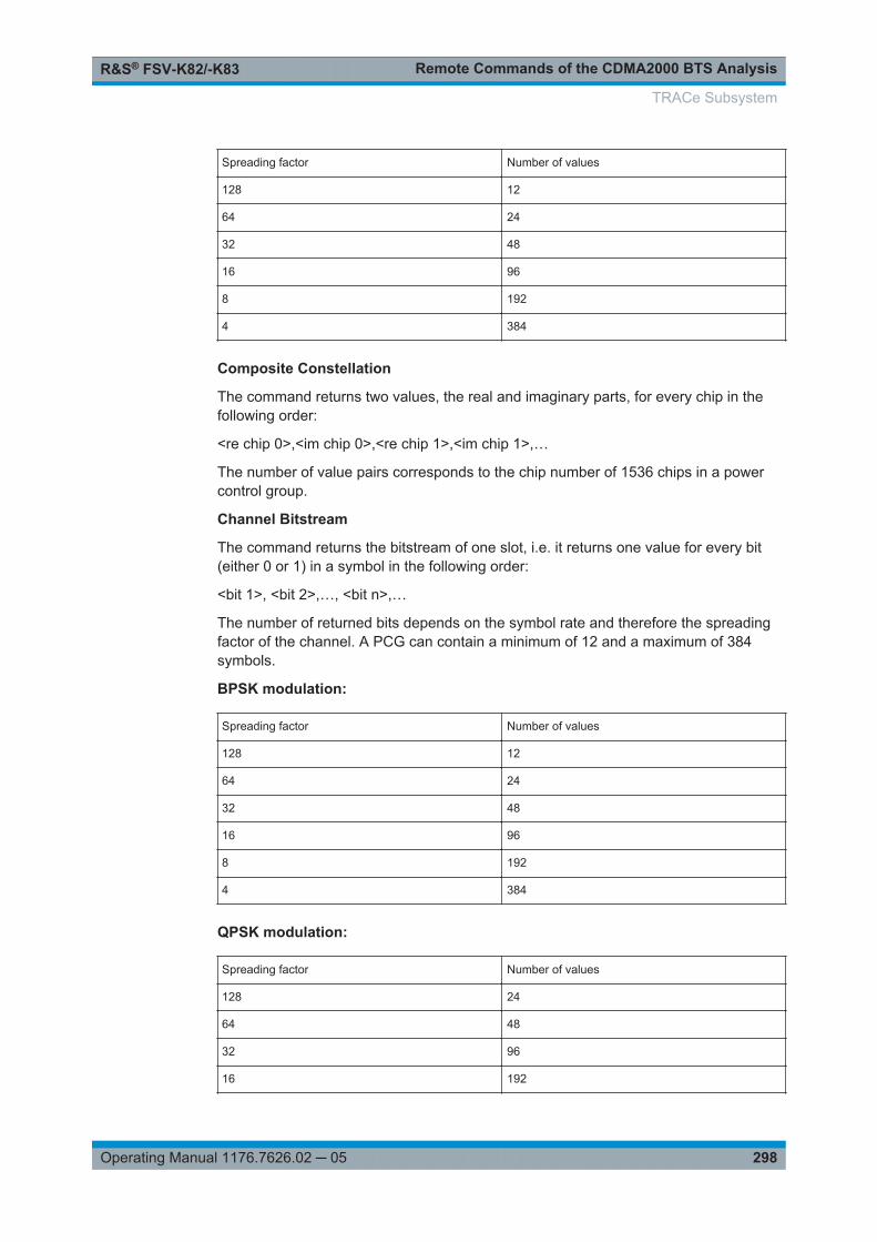
Remote Commands of the CDMA2000 BTS AnalysisR&S® FSV-K82/-K83
298Operating Manual 1176.7626.02 ─ 05
Spreading factor Number of values
128 12
64 24
32 48
16 96
8 192
4 384
Composite Constellation
The command returns two values, the real and imaginary parts, for every chip in thefollowing order:
<re chip 0>,<im chip 0>,<re chip 1>,<im chip 1>,…
The number of value pairs corresponds to the chip number of 1536 chips in a powercontrol group.
Channel Bitstream
The command returns the bitstream of one slot, i.e. it returns one value for every bit(either 0 or 1) in a symbol in the following order:
<bit 1>, <bit 2>,…, <bit n>,…
The number of returned bits depends on the symbol rate and therefore the spreadingfactor of the channel. A PCG can contain a minimum of 12 and a maximum of 384symbols.
BPSK modulation:
Spreading factor Number of values
128 12
64 24
32 48
16 96
8 192
4 384
QPSK modulation:
Spreading factor Number of values
128 24
64 48
32 96
16 192
TRACe Subsystem

Remote Commands of the CDMA2000 BTS AnalysisR&S® FSV-K82/-K83
299Operating Manual 1176.7626.02 ─ 05
8 384
4 768
8PSK modulation:
Spreading factor Number of values
32 144
16QAM modulation:
Spreading factor Number of values
32 192
Depending on the modulation type, a symbol consists of a different number of bits. ForBPSK modulated signals there is one bit per symbol, for QPSK modulated signalsthere are 2 bits per symbol, for 8-PSK modulated signals there are 3 bits per symboland for 16QAM modulated signal there are 4 bits per symbol.
With transmit diversity activated the values reduce to the half.
Magnitude Error vs Chip
The comand returns a list of magnitude error values of all chips at the selected PCG.The values are calculated as the magnitude difference between the received signaland the reference signal for each chip in %, and are normalized to the square root ofthe average power at the selected PCG.
Phase Error vs Chip
The comand returns a list of phase error values of all chips at the selected PCG. Thevalues are calculated as the phase difference between the received signal and the ref-erence signal for each chip in degrees, and are normalized to the square root of theaverage power at the selected PCG.
Symbol Magnitude Error
The comand returns the magnitude error in % of each symbol at the selected PCG.The number of the symbols depends on the spreading factor of the selected channel:
NOFSymbols=10*2(8-CodeClass)
Symbol Phase Error
The comand returns the phase error in degrees of each symbol at the selected PCG.The number of the symbols depends on the spreading factor of the selected channel:
NOFSymbols=10*2(8-CodeClass)
TRACe Subsystem

Remote Commands of the CDMA2000 BTS AnalysisR&S® FSV-K82/-K83
300Operating Manual 1176.7626.02 ─ 05
7.9 Other Commands Referenced in this Manual
The following commands are identical to those in the base unit and are included in thismanual only because they are specifically referenced to here.
See also Chapter 7.6.2, "Other SENSe Commands Referenced in this Manual",on page 252 and Chapter 7.2.3, "Other CALCulate Commands Referenced in thisManual", on page 191
7.9.1 INPut commands.........................................................................................................300
7.9.2 TRIGger Commands................................................................................................... 307
7.9.3 Other Referenced Commands.................................................................................... 310
7.9.1 INPut commands
INPut:ATTenuation <Value>
This command programs the input attenuator. To protect the input mixer against dam-age from overloads, the setting 0 dB can be obtained by entering numerals, not byusing the DOWN command.
The RF attenuation can be set in 5 dB steps (R&S FSV with option R&S FSV-B25 orR&S FSVA: 1 dB steps). The range is specified in the data sheet. If the current refer-ence level cannot be set for the set RF attenuation, the reference level is adjustedaccordingly.
In the default state with "Spectrum" mode, the attenuation set on the step attenuator iscoupled to the reference level of the instrument. If the attenuation is programmeddirectly, the coupling to the reference level is switched off.
This function is not available if the R&S Digital I/Q Interface (R&S FSV-B17) is active.
Parameters:<Value> *RST: 10 dB (AUTO is set to ON)
Example: INP:ATT 30dBSets the attenuation on the attenuator to 30 dB and switches offthe coupling to the reference level.
Mode: all
Manual operation: See "RF Atten Manual/Mech Att Manual" on page 82
INPut:ATTenuation:AUTO <State>
This command automatically couples the input attenuation to the reference level (stateON) or switches the input attenuation to manual entry (state OFF).
This function is not available if the R&S Digital I/Q Interface (R&S FSV-B17) is active.
Other Commands Referenced in this Manual

Remote Commands of the CDMA2000 BTS AnalysisR&S® FSV-K82/-K83
301Operating Manual 1176.7626.02 ─ 05
Parameters:<State> ON | OFF
*RST: ON
Example: INP:ATT:AUTO ONCouples the attenuation set on the attenuator to the referencelevel.
Manual operation: See "RF Atten Auto/Mech Att Auto" on page 83
INPut:COUPling <CouplingType>
Toggles the RF input of the R&S FSV/FSVA between AC and DC coupling.
This function is not available if the R&S Digital I/Q Interface (R&S FSV-B17) is active.
Parameters:<CouplingType> AC | DC
*RST: AC
Example: INP:COUP DCManual operation: See "Input (AC/DC)" on page 84
INPut:DIQ:CDEVice
This command queries the current configuration and the status of the digital basebandinput from the optional R&S Digital I/Q Interface (option R&S FSV-B17).
For details see the section "Interface Status Information" for the R&S Digital I/Q Inter-face (R&S FSV-B17) in the description of the base unit.
Return values: <ConnState> Defines whether a device is connected or not.
0No device is connected.1A device is connected.
<DeviceName> Device ID of the connected device
<SerialNumber> Serial number of the connected device
<PortName> Port name used by the connected device
<SampleRate> Maximum or currently used sampling rate of the connecteddevice in Hz (depends on the used connection protocol version;indicated by <SampleRateType> parameter)
<MaxTransferRate> Maximum data transfer rate of the connected device in Hz
Other Commands Referenced in this Manual

Remote Commands of the CDMA2000 BTS AnalysisR&S® FSV-K82/-K83
302Operating Manual 1176.7626.02 ─ 05
<ConnProtState> State of the connection protocol which is used to identify theconnected device.Not StartedHas to be StartedStartedPassedFailedDone
<PRBSTestState> State of the PRBS test.Not StartedHas to be StartedStartedPassedFailedDone
<SampleRateType> 0Maximum sampling rate is displayed1Current sampling rate is displayed
<Placeholder> for future use; currently "0"
Example: INP:DIQ:CDEV?Result:1,SMU200A,103634,OutA,70000000,100000000,Passed,Not Started,0,0
Mode: IQ, VSA, EVDO, CDMA, WCDMA, GSM, ADEMOD, TDS
Manual operation: See "Connected Device" on page 94See "Digital IQ Info" on page 95
INPut:DIQ:RANGe:AUTO <State>
If enabled, the digital input fullscale level is automatically set to the value provided bythe connected device (if available).
This command is only available if the optional Digital Baseband interface (optionR&S FSV-B17) is installed.
For details see the Digital Baseband Interface (R&S FSV-B17) description of the baseunit.
Parameters:<State> ON | OFF
*RST: OFF
Example: INP:DIQ:RANG:AUTO ON
Other Commands Referenced in this Manual

Remote Commands of the CDMA2000 BTS AnalysisR&S® FSV-K82/-K83
303Operating Manual 1176.7626.02 ─ 05
Mode: IQ, VSA, EVDO, CDMA, WCDMA, GSM, ADEMOD, TDS
INPut:DIQ:RANGe:COUPling <State>
If enabled, the reference level for digital input is adjusted to the full scale level automat-ically if the fullscale level changes.
This command is only available if the optional R&S Digital I/Q Interface (optionR&S FSV-B17) is installed.
For details see the R&S Digital I/Q Interface (R&S FSV-B17) description of the baseunit.
Parameters:<State> ON | OFF
*RST: OFF
Example: INP:DIQ:RANG:COUP OFFMode: IQ, VSA, EVDO, CDMA, WCDMA, GSM, ADEMOD, TDS
Manual operation: See "Adjust Reference Level to Full Scale Level" on page 94
INPut:DIQ:RANGe[:UPPer] <Level>
Defines or queries the "Full Scale Level", i.e. the level that should correspond to an I/Qsample with the magnitude "1".
It can be defined either in dBm or Volt (see "Full Scale Level" on page 94).
This command is only available if the optional R&S Digital I/Q Interface (optionR&S FSV-B17) is installed.
For details see the R&S Digital I/Q Interface (R&S FSV-B17) description of the baseunit.
Parameters:<Level> <numeric value>
Range: 70.711 nV to 7.071 V*RST: 1 V
Example: INP:DIQ:RANG 1VMode: A, IQ, NF, TDS, VSA, CDMA, EVDO, WCDMA, ADEMOD,
GSM, OFDM, OFDMA/WiBro, WLAN
Manual operation: See "Full Scale Level" on page 94
INPut:DIQ:RANGe[:UPPer]:UNIT <Unit>
Defines the unit of the full scale level (see "Level Unit" on page 94). The availability ofunits depends on the measurement application you are using.
This command is only available if the optional R&S Digital I/Q Interface (optionR&S FSV-B17) is installed.
Other Commands Referenced in this Manual

Remote Commands of the CDMA2000 BTS AnalysisR&S® FSV-K82/-K83
304Operating Manual 1176.7626.02 ─ 05
For details see the R&S Digital I/Q Interface (R&S FSV-B17) description of the baseunit.
Parameters:<Level> V | dBm | dBpW | W | dBmV | dBuV | dBuA | A
*RST: Volt
Example: INP:DIQ:RANG:UNIT AMode: IQ, VSA, EVDO, CDMA, WCDMA, GSM, ADEMOD, TDS
Manual operation: See "Level Unit" on page 94
INPut:DIQ:SRATe <SampleRate>
This command specifies or queries the sample rate of the input signal from the R&SDigital I/Q Interface (see "Input Sample Rate" on page 94).
This command is only available if the optional R&S Digital I/Q Interface (optionR&S FSV-B17) is installed.
For details see the R&S Digital I/Q Interface (R&S FSV-B17) description of the baseunit.
Parameters:<SampleRate> Range: 1 Hz to 10 GHz
*RST: 32 MHz
Example: INP:DIQ:SRAT 200 MHz
Mode: A, IQ, NF, TDS, VSA, CDMA, EVDO, WCDMA, ADEMOD,GSM, OFDM, OFDMA/WiBro, WLAN
Manual operation: See "Input Sample Rate" on page 94
INPut:DIQ:SRATe:AUTO <State>
If enabled, the sample rate of the digital baseband IQ input signal is set automaticallyby the connected device, if the currently used sample rate is provided (indicated by the<SampleRateType> parameter in the result of the INPut:DIQ:CDEVice command.
This command is only available if the optional R&S Digital I/Q Interface (optionR&S FSV-B17) is installed.
For details see the R&S Digital I/Q Interface (B17) description of the base unit.
Parameters:<State> ON | OFF
*RST: OFF
Example: INP:DIQ:SRAT:AUTO ONMode: IQ, VSA, EVDO, CDMA, WCDMA, GSM, ADEMOD, TDS
Other Commands Referenced in this Manual

Remote Commands of the CDMA2000 BTS AnalysisR&S® FSV-K82/-K83
305Operating Manual 1176.7626.02 ─ 05
INPut:EATT <Attenuation>
This command defines the electronic attenuation.
If necessary, the command also turns the electronic attenuator on.
This command is only available with option R&S FSV-B25, but not if R&S FSV-B17 isactive.
The attenuation can be varied in 1 dB steps from 0 to 25 dB. Other entries are roundedto the next lower integer value.
If the defined reference level cannot be set for the given RF attenuation, the referencelevel is adjusted accordingly and the warning "Limit reached" is output.
Parameters:<Attenuation> 0...25
*RST: 0 dB (OFF)
Example: INP1:EATT 10 dBMode: all
Manual operation: See "El Atten Mode (Auto/Man)" on page 83
INPut:EATT:AUTO <State>
This command switches the automatic behaviour of the electronic attenuator on or off.If activated, electronic attenuation is used to reduce the operation of the mechanicalattenuation whenever possible.
This command is only available with option R&S FSV-B25, but not if R&S FSV-B17 isactive.
Parameters:<State> ON | OFF
*RST: ON
Example: INP1:EATT:AUTO OFFMode: all
Manual operation: See "El Atten On/Off" on page 83See "El Atten Mode (Auto/Man)" on page 83
INPut:EATT:STATe <State>
This command turns the electronic attenuator on or off.
This command is only available with option R&S FSV-B25, but not if R&S FSV-B17 isactive.
Parameters:<State> ON | OFF
*RST: OFF
Other Commands Referenced in this Manual

Remote Commands of the CDMA2000 BTS AnalysisR&S® FSV-K82/-K83
306Operating Manual 1176.7626.02 ─ 05
Example: INP:EATT:STAT ONSwitches the electronic attenuator into the signal path.
INPut:FILTer:YIG[:STATe] <State>
If the option R&S FSVA-B11 is installed, the YIG preselector can be bypassed.
This function is only available for R&S FSVA instruments.
If the YIG preselector at the input of the R&S FSVA is removed from the signal path,you can use the maximum bandwidth for signal analysis. However, image-frequencyrejection is no longer ensured.
Note that the YIG preselector is active only on frequencies greater than 7 GHz. There-fore, switching the YIG preselector on and off has no effect if the frequency is belowthat value.
Parameters:<State> ON | OFF | 0 | 1
*RST: 1 (0 for I/Q Analyzer, GSM, VSA measurements)
Example: INP:FILT:YIG OFFDeactivates the YIG preselector.
Manual operation: See "(Bypassing the ) YIG Filter" on page 137
INPut:GAIN:STATe <State>
This command turns the 20 dB preamplifier on and off.
With option R&S FSV-B22, the preamplifier only has an effect below 7 GHz.
With option R&S FSV-B24, the amplifier applies to the entire frequency range.
This command is not available when using R&S Digital I/Q Interface (R&S FSV-B17).
Parameters:<State> ON | OFF
*RST: OFF
Example: INP:GAIN:STAT ONTurns the preamplifier on.
Manual operation: See "Preamp On/Off" on page 63
INPut:IMPedance <Impedance>
This command selects the nominal input impedance.
75 Ω should be selected if the 50 Ω input impedance is transformed to a higher impe-dance using a 75 Ω adapter of the RAZ type (= 25 Ω in series to the input impedanceof the instrument). The correction value in this case is 1.76 dB = 10 log (75Ω/50Ω).
This function is not available if the R&S Digital I/Q Interface (R&S FSV-B17) is active.
Other Commands Referenced in this Manual

Remote Commands of the CDMA2000 BTS AnalysisR&S® FSV-K82/-K83
307Operating Manual 1176.7626.02 ─ 05
Parameters:<Impedance> 50 | 75
*RST: 50 Ω
Example: INP:IMP 75Manual operation: See "Input 50 Ω/75 Ω " on page 136
INPut:SELect <Source>
This command selects the signal source for measurements.
Parameters:<Source> RF | DIQ
RFRadio Frequency ("RF INPUT" connector)DIQDigital IQ (only available with R&S Digital I/Q Interface, optionR&S FSV-B17)*RST: RF
Example: INP:SEL RF
Mode: A, IQ, NF, TDS, VSA, CDMA, EVDO, WCDMA, ADEMOD,GSM, OFDM, OFDMA/WiBro, WLAN
Manual operation: See "Input Path" on page 94
7.9.2 TRIGger Commands
TRIGger<n>[:SEQuence]:LEVel:BBPower <Level>
This command sets the level of the baseband power trigger source (for digital input viathe R&S Digital I/Q Interface, R&S FSV-B17).
Suffix: <n>
.irrelevant
Parameters:<Level> Range: -50 dBm to +20 dBm
*RST: -20 DBM
Example: TRIG:LEV:BB -30DBMMode: All
TRIGger<n>[:SEQuence]:BBPower:HOLDoff <Value>
This command sets the holding time before the next BB power trigger event (for digitalinput via the R&S Digital I/Q Interface, R&S FSV-B17).
Other Commands Referenced in this Manual

Remote Commands of the CDMA2000 BTS AnalysisR&S® FSV-K82/-K83
308Operating Manual 1176.7626.02 ─ 05
Suffix: <n>
.irrelevant
Parameters:<Value> *RST: 150 ns
Example: TRIG:SOUR BBPSets the baseband power trigger source.TRIG:BBP:HOLD 200 nsSets the holding time to 200 ns.
Mode: all
TRIGger<n>[:SEQuence]:IFPower:HOLDoff <Value>
This command sets the holding time before the next IF power trigger event.
Suffix: <n>
.irrelevant
Parameters:<Value> *RST: 150 ns
Example: TRIG:SOUR IFPSets the IF power trigger source.TRIG:IFP:HOLD 200 nsSets the holding time to 200 ns.
TRIGger<n>[:SEQuence]:IFPower:HYSTeresis <Value>
This command sets the limit that the hysteresis value for the IF power trigger has to fallbelow in order to trigger the next measurement.
Suffix: <n>
.irrelevant
Parameters:<Value> *RST: 3 dB
Example: TRIG:SOUR IFPSets the IF power trigger source.TRIG:IFP:HYST 10DBSets the hysteresis limit value.
TRIGger<n>[:SEQuence]:HOLDoff[:TIME] <Delay>
This command defines the length of the trigger delay.
A negative delay time (pretrigger) can be set in zero span only.
Suffix: <n>
.irrelevant
Other Commands Referenced in this Manual
Remote Commands of the CDMA2000 BTS AnalysisR&S® FSV-K82/-K83
309Operating Manual 1176.7626.02 ─ 05
Parameters:<Delay> Range: zero span: -sweeptime (see data sheet) to 30 s;
span: 0 to 30 s*RST: 0 s
Example: TRIG:HOLD 500usManual operation: See "Trigger Offset" on page 65
TRIGger<n>[:SEQuence]:LEVel[:EXTernal] <TriggerLevel>
This command sets the level of the external trigger source in Volt.
Suffix: <n>
.irrelevant
Parameters:<TriggerLevel> Range: 0.5 V to 3.5 V
*RST: 1.4 V
Example: TRIG:LEV 2V
TRIGger<n>[:SEQuence]:SLOPe <Type>
This command selects the slope of the trigger signal. The selected trigger slopeapplies to all trigger signal sources.
Suffix: <n>
.irrelevant
Parameters:<Type> POSitive | NEGative
*RST: POSitive
Example: TRIG:SLOP NEGManual operation: See "Trigger Polarity" on page 65
TRIGger<n>[:SEQuence]:SOURce <Source>
This command selects the trigger source.
IF power and RF power triggers are not available together with the bandwidth exten-sion option R&S FSV-B160.
For details on trigger modes refer to the "Trg/Gate Source" softkey in the base unitdescription.
Suffix: <n>
.irrelevant
Other Commands Referenced in this Manual
Remote Commands of the CDMA2000 BTS AnalysisR&S® FSV-K82/-K83
310Operating Manual 1176.7626.02 ─ 05
Parameters:<Source> IMMediate
Free RunEXTernExternal triggerIFPowerPower trigger at the second intermediate frequencyRFPowerPower trigger at the first intermediate frequencyTIMETime intervalPSENExternal power sensor (requires R&S FSV-K9 option)*RST: IMMediate
Example: TRIG:SOUR EXTSelects the external trigger input as source of the trigger signal
Manual operation: See "Trigger Source Free Run" on page 64See "Trigger Source External" on page 64
7.9.3 Other Referenced Commands
ABORt
This command aborts a current measurement and resets the trigger system.
Example: ABOR;INIT:IMMMode: all
Manual operation: See "Meas Start/Stop" on page 120
DIAGnostic<n>:SERVice:NSOurce <State>
This command switches the 28 V supply of the noise source on the front panel on oroff.
Suffix: <n>
.irrelevant
Parameters:<State> ON | OFF
*RST: OFF
Example: DIAG:SERV:NSO ONManual operation: See "Noise Source" on page 93
Other Commands Referenced in this Manual

Remote Commands of the CDMA2000 BTS AnalysisR&S® FSV-K82/-K83
311Operating Manual 1176.7626.02 ─ 05
FORMat:DEXPort:DSEParator <Separator>
This command defines which decimal separator (decimal point or comma) is to beused for outputting measurement data to the file in ASCII format. Different languagesof evaluation programs (e.g. MS-Excel) can thus be supported.
Parameters:<Separator> POINt | COMMA
*RST: (factory setting is POINt; *RST does not affect set-ting)
Example: FORM:DEXP:DSEP POINSets the decimal point as separator.
Manual operation: See "ASCII File Export" on page 117See "Decim Sep" on page 117
INITiate<n>:CONMeas
This command restarts a measurement that has been stopped in single sweep mode.
The measurement is restarted at the first sweep point.
As opposed to INITiate<n>[:IMMediate], this command does not reset traces inmaxhold, minhold or average mode. Therefore it can be used to continue measure-ments using max hold or averaging functions.
In single sweep mode, you can synchronize to the end of the measurement with *OPC,*OPC? or *WAI. In continuous sweep mode, synchronization to the end of the mea-surement is not possible. Thus, it is not recommended that you use continuous sweepmode in remote control, as results like trace data or markers are only valid after a sin-gle sweep end synchronization.
Suffix: <n>
.irrelevant
Example: INIT:CONT OFFSwitches to single sweep mode.DISP:WIND:TRAC:MODE AVERSwitches on trace averaging.SWE:COUN 20Setting the sweep counter to 20 sweeps.INIT;*WAIStarts the measurement and waits for the end of the 20 sweeps.INIT:CONM;*WAIContinues the measurement (next 20 sequences) and waits forthe end.
Manual operation: See "Continue Single Sweep" on page 84
Other Commands Referenced in this Manual

Remote Commands of the CDMA2000 BTS AnalysisR&S® FSV-K82/-K83
312Operating Manual 1176.7626.02 ─ 05
INITiate<n>:CONTinuous <State>
This command determines whether the trigger system is continuously initiated (contin-uous) or performs single measurements (single).
The sweep is started immediately.
Suffix: <n>
.irrelevant
Parameters:<State> ON | OFF
*RST: ON
Example: INIT:CONT OFFSwitches the sequence to single sweep.INIT:CONT ONSwitches the sequence to continuous sweep.
Mode: all
Manual operation: See "Continuous Sweep" on page 84See "Single Sweep" on page 84
INITiate<n>:ESPectrum
This command starts a Spectrum Emission Mask measurement.
Suffix: <n>
.irrelevant
Example: INIT:ESPStarts a Spectrum Emission Mask measurement.
Manual operation: See "Meas Start/Stop" on page 120
INITiate<n>[:IMMediate]
The command initiates a new measurement sequence.
With sweep count > 0 or average count > 0, this means a restart of the indicated num-ber of measurements. With trace functions MAXHold, MINHold and AVERage, the pre-vious results are reset on restarting the measurement.
In single sweep mode, you can synchronize to the end of the measurement with *OPC,*OPC? or *WAI. In continuous sweep mode, synchronization to the end of the mea-surement is not possible. Thus, it is not recommended that you use continuous sweepmode in remote control, as results like trace data or markers are only valid after a sin-gle sweep end synchronization.
Suffix: <n>
.irrelevant
Other Commands Referenced in this Manual

Remote Commands of the CDMA2000 BTS AnalysisR&S® FSV-K82/-K83
313Operating Manual 1176.7626.02 ─ 05
Example: INIT:CONT OFFSwitches to single sweep mode.DISP:WIND:TRAC:MODE AVERSwitches on trace averaging.SWE:COUN 20Setting the sweep counter to 20 sweeps.INIT;*WAIStarts the measurement and waits for the end of the 20 sweeps.
Mode: all
MMEMory:STORe<n>:LIST <FileName>
This command stores the current list evaluation results in a <file name>.dat file.The file consists of a data section containing the list evaluation results.
Suffix: <n>
.irrelevant
Parameters:<FileName> <file name>
Example: MMEM:STOR:LIST 'test'Stores the current list evaluation results in the test.dat file.
Manual operation: See "Save Evaluation List" on page 116See "ASCII File Export" on page 117
MMEMory:STORe<n>:TRACe <Trace>, <FileName>
This command stores the selected trace in the specified window in a file with ASCII for-mat. The file format is described in Chapter 6.4.7, "ASCII File Export Format",on page 161
The decimal separator (decimal point or comma) for floating-point numerals containedin the file is defined with the FORMat:DEXPort:DSEParator command (seeFORMat:DEXPort:DSEParator on page 311).
Suffix: <n>
.window; For applications that do not have more than 1 measure-ment window, the suffix <n> is irrelevant.
Parameters:<Trace> 1 to 6
Selected a trace.
<FileName> DOS file nameThe file name includes indication of the path and the drive name.Indication of the path complies with DOS conventions.
Example: MMEM:STOR:TRAC 3,'TEST.ASC'Stores trace 3 in the file TEST.ASC.
Other Commands Referenced in this Manual
Remote Commands of the CDMA2000 BTS AnalysisR&S® FSV-K82/-K83
314Operating Manual 1176.7626.02 ─ 05
OUTPut:IF[:SOURce] <Source>
This command selects the source of the IF output.
Parameters:<Source> IF
Outputs the intermediate frequency.VIDeoOutputs the video signal (200 mV).*RST: IF
Example: OUTP:IF VIDSelects the video signal for the IF output connector.
Manual operation: See "Video Output" on page 150
OUTPut:TRIGger <PortLevel>
This command selects level of the Trigger Out port. Thus, you can trigger an additionaldevice via the external trigger port, for example.
Parameters:<PortLevel> LOW | HIGH
*RST: LOW
Example: OUTP:TRIG HIGHManual operation: See "Trigger Out" on page 150
SYSTem:DISPlay:UPDate <State>
In remote control mode, this command switches on or off the instrument display. Ifswitched on, only the diagrams, traces and display fields are displayed and updated.
The best performance is obtained if the display output is switched off during remotecontrol.
Parameters:<State> ON | OFF
*RST: OFF
Example: SYST:DISP:UPD ON
Other Commands Referenced in this Manual

Status Reporting System of the CDMA2000 BTS Analysis (option K82)R&S® FSV-K82/-K83
315Operating Manual 1176.7626.02 ─ 05
8 Status Reporting System of the CDMA2000BTS Analysis (option K82)Detailed information on the status registers of the base system is given in the base unitdescription. In this section, only the new and altered status registers/its for theCDMA2000 BTS Analysis option (K82) are described.
The R&S FSV-K82 uses the STATus:QUEStionable:SYNC register.
Although this register is provided by the base system, the CDMA2000 BTS Analysisoption (K82) uses different bits and definitions.
The STATus:QUEStionable:SYNC register contains information on the error situa-tion in the code domain analysis of the CDMA2000 BTS Analysis option. The bits canbe queried with commands STATus:QUEStionable:SYNC:CONDition? andSTATus:QUEStionable:SYNC[:EVENt]?.
Bit No Meaning
0 This bit is not used.
1 Frame Sync failed. This bit is set when synchronization is not possible withinthe application. Possible reasons:
Incorrectly set frequency
Incorrectly set level
Incorrectly set PN Offset
Incorrectly set values for Swap IQ
Invalid signal at input
2 to 14 These bits are not used.
15 This bit is always 0.

GlossaryR&S® FSV-K82/-K83
316Operating Manual 1176.7626.02 ─ 05
9 GlossaryFor a more comprehensive glossary refer to the CDMA2000 standard.
APICH auxiliary pilot channel
ATDPCH auxiliary transmit diversity pilot channel
BCH broadcast channel.
CACH common assignment channel
CCCH common control channel
CDEP code domain error power
CDP code domain power
Composite EVM in accordance with the 3GPP2 specifications, determines the square rootof the squared error between the real and the imaginary parts of the testsignal and an ideally generated reference signal (EVM referred to the totalsignal) in a composite EVM measurement.
CPCCH common power control channel
Crest factor ratio of peak to average value of the signal
Inactive Channel Threshold minimum power that a single channel must have compared with the totalsignal to be recognized as an active channel.
MC1 multi-carrier1 (one carrier system 1X).
MC2 multi-carrier3 (three carrier system 3X).
OTD orthogonal transmit diversity, two antennas used
PCG power control group: name in CDMA2000 system for 1536 chips or 1.25ms interval; transmitter power is constant during a power control group
PCH paging channel
PDCH packet data channel
PDCCH packet data control channel
PICH pilot channel 0.64
RC radio configuration; definition of sampling rate, permissible data rates,modulation types and use of special channels, and transmit diversity
Set a group of 64 consecutive PCGs
SF spreading factor
SYNC synchronisation channel 32.64
TD transmit diversity, two antennas used
TDPICH transmit diversity pilot channel 16.128
x.y Walsh code x.y, with code number x and spreading factor y of the channel

AppendixR&S® FSV-K82/-K83
317Operating Manual 1176.7626.02 ─ 05
10 AppendixHadamard and BitReverse Code Tables
The following tables show the code sequences with Hadamard and BitReverse ordersfor the Code Domain Power and Code Domain Error Power result displays.
As an example, the corresponding cells for channel 8.32 (channel number 8 forspreading factor 32) are marked to show where the different codes of this channel arelocated.
Figure 10-1: Codetable for base spreading factor 64
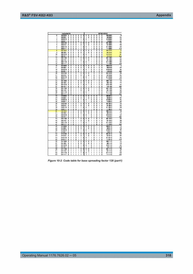
AppendixR&S® FSV-K82/-K83
318Operating Manual 1176.7626.02 ─ 05
Figure 10-2: Code table for base spreading factor 128 (part1)

AppendixR&S® FSV-K82/-K83
319Operating Manual 1176.7626.02 ─ 05
Figure 10-3: Code table for base spreading factor 128 (part 2)
List of CommandsR&S® FSV-K82/-K83
320Operating Manual 1176.7626.02 ─ 05
List of Commands[SENSe:]ADJust:ALL..................................................................................................................................... 252[SENSe:]ADJust:CONFiguration:HYSTeresis:LOWer...................................................................................252[SENSe:]ADJust:CONFiguration:HYSTeresis:UPPer....................................................................................253[SENSe:]ADJust:CONFigure:LEVel:DURation.............................................................................................. 253[SENSe:]ADJust:CONFigure:LEVel:DURation:MODE.................................................................................. 253[SENSe:]ADJust:FREQuency........................................................................................................................254[SENSe:]ADJust:LEVel..................................................................................................................................254[SENSe:]AVERage<n>:COUNt......................................................................................................................289[SENSe:]AVERage<n>[:STATe<Trace>].......................................................................................................290[SENSe:]BANDwidth|BWIDth:VIDeo............................................................................................................. 268[SENSe:]BANDwidth|BWIDth:VIDeo:AUTO.................................................................................................. 269[SENSe:]BANDwidth|BWIDth:VIDeo:RATio.................................................................................................. 269[SENSe:]BANDwidth|BWIDth:VIDeo:TYPE...................................................................................................269[SENSe:]BANDwidth|BWIDth[:RESolution]................................................................................................... 266[SENSe:]BANDwidth|BWIDth[:RESolution]:AUTO........................................................................................ 267[SENSe:]BANDwidth|BWIDth[:RESolution]:FFT............................................................................................267[SENSe:]BANDwidth|BWIDth[:RESolution]:RATio........................................................................................ 268[SENSe:]BANDwidth|BWIDth[:RESolution]:TYPE.........................................................................................268[SENSe:]CDPower:ANTenna.........................................................................................................................244[SENSe:]CDPower:CODE............................................................................................................................. 244[SENSe:]CDPower:ICThreshold.................................................................................................................... 245[SENSe:]CDPower:IQLength.........................................................................................................................245[SENSe:]CDPower:LCODe:MASK.................................................................................................................246[SENSe:]CDPower:LCODe:MODE ...............................................................................................................247[SENSe:]CDPower:LCODe:OFFSet ............................................................................................................. 246[SENSe:]CDPower:LEVel:ADJust..................................................................................................................245[SENSe:]CDPower:MAPPing.........................................................................................................................245[SENSe:]CDPower:NORMalize..................................................................................................................... 247[SENSe:]CDPower:ORDer.............................................................................................................................247[SENSe:]CDPower:OVERview...................................................................................................................... 248[SENSe:]CDPower:PNOFfset........................................................................................................................248[SENSe:]CDPower:PPReference.................................................................................................................. 249[SENSe:]CDPower:PREFerence................................................................................................................... 249[SENSe:]CDPower:QINVert...........................................................................................................................249[SENSe:]CDPower:SBANd............................................................................................................................250[SENSe:]CDPower:SET.................................................................................................................................250[SENSe:]CDPower:SET:COUNt.................................................................................................................... 250[SENSe:]CDPower:SFACtor..........................................................................................................................250[SENSe:]CDPower:SLOT.............................................................................................................................. 251[SENSe:]CDPower:TPMeas.......................................................................................................................... 251[SENSe:]ESPectrum:BWID............................................................................................................................255[SENSe:]ESPectrum:FILTer[:RRC]:ALPHa................................................................................................... 256[SENSe:]ESPectrum:FILTer[:RRC][:STATe]................................................................................................. 255[SENSe:]ESPectrum:HighSPeed...................................................................................................................256[SENSe:]ESPectrum:PRESet:RESTore........................................................................................................ 257[SENSe:]ESPectrum:PRESet:STORe........................................................................................................... 257[SENSe:]ESPectrum:PRESet[:STANdard].................................................................................................... 257

List of CommandsR&S® FSV-K82/-K83
321Operating Manual 1176.7626.02 ─ 05
[SENSe:]ESPectrum:RANGe<range>:BANDwidth:VIDeo.............................................................................258[SENSe:]ESPectrum:RANGe<range>:BANDwidth[:RESolution]...................................................................257[SENSe:]ESPectrum:RANGe<range>:COUNt...............................................................................................258[SENSe:]ESPectrum:RANGe<range>:DELete.............................................................................................. 258[SENSe:]ESPectrum:RANGe<range>:FILTer:TYPE..................................................................................... 259[SENSe:]ESPectrum:RANGe<range>:INPut:ATTenuation............................................................................260[SENSe:]ESPectrum:RANGe<range>:INPut:ATTenuation:AUTO.................................................................261[SENSe:]ESPectrum:RANGe<range>:INPut:GAIN:STATe........................................................................... 261[SENSe:]ESPectrum:RANGe<range>:INSert................................................................................................261[SENSe:]ESPectrum:RANGe<range>:LIMit<source>:ABSolute:STARt........................................................262[SENSe:]ESPectrum:RANGe<range>:LIMit<source>:ABSolute:STOP.........................................................262[SENSe:]ESPectrum:RANGe<range>:LIMit<source>:RELative:STARt........................................................ 263[SENSe:]ESPectrum:RANGe<range>:LIMit<source>:RELative:STOP.........................................................263[SENSe:]ESPectrum:RANGe<range>:LIMit<source>:STATe....................................................................... 263[SENSe:]ESPectrum:RANGe<range>:RLEVel..............................................................................................264[SENSe:]ESPectrum:RANGe<range>:SWEep:TIME.................................................................................... 264[SENSe:]ESPectrum:RANGe<range>:SWEep:TIME:AUTO......................................................................... 265[SENSe:]ESPectrum:RANGe<range>:TRANsducer......................................................................................265[SENSe:]ESPectrum:RANGe<range>[:FREQuency]:STARt.........................................................................259[SENSe:]ESPectrum:RANGe<range>[:FREQuency]:STOP..........................................................................260[SENSe:]ESPectrum:RRANge.......................................................................................................................266[SENSe:]ESPectrum:RTYPe......................................................................................................................... 266[SENSe:]FREQuency:CENTer.......................................................................................................................270[SENSe:]FREQuency:CENTer:STEP............................................................................................................ 270[SENSe:]FREQuency:CENTer:STEP:AUTO................................................................................................. 271[SENSe:]FREQuency:CENTer:STEP:LINK................................................................................................... 271[SENSe:]FREQuency:CENTer:STEP:LINK:FACTor......................................................................................271[SENSe:]FREQuency:OFFSet.......................................................................................................................272[SENSe:]FREQuency:SPAN..........................................................................................................................272[SENSe:]FREQuency:SPAN:FULL................................................................................................................272[SENSe:]FREQuency:STARt.........................................................................................................................272[SENSe:]FREQuency:STOP..........................................................................................................................273[SENSe:]POWer:ACHannel:ACPairs.............................................................................................................273[SENSe:]POWer:ACHannel:BANDwidth|BWIDth:ACHannel.........................................................................274[SENSe:]POWer:ACHannel:BANDwidth|BWIDth:ALTernate<channel>........................................................275[SENSe:]POWer:ACHannel:BANDwidth|BWIDth[:CHANnel<channel>]....................................................... 274[SENSe:]POWer:ACHannel:FILTer:ALPHa:ACHannel..................................................................................275[SENSe:]POWer:ACHannel:FILTer:ALPHa:ALTernate<channel>................................................................ 275[SENSe:]POWer:ACHannel:FILTer:ALPHa:CHANnel<channel>.................................................................. 276[SENSe:]POWer:ACHannel:FILTer[:STATe]:ACHannel................................................................................276[SENSe:]POWer:ACHannel:FILTer[:STATe]:ALTernate<channel>...............................................................276[SENSe:]POWer:ACHannel:FILTer[:STATe]:CHANnel<channel>................................................................ 276[SENSe:]POWer:ACHannel:MODE............................................................................................................... 277[SENSe:]POWer:ACHannel:NAME:ACHannel.............................................................................................. 277[SENSe:]POWer:ACHannel:NAME:ALTernate<channel>.............................................................................278[SENSe:]POWer:ACHannel:NAME:CHANnel<channel>...............................................................................278[SENSe:]POWer:ACHannel:PRESet............................................................................................................. 278[SENSe:]POWer:ACHannel:PRESet:RLEVel................................................................................................279[SENSe:]POWer:ACHannel:REFerence:AUTO ONCE................................................................................. 279[SENSe:]POWer:ACHannel:REFerence:TXCHannel:AUTO......................................................................... 279
List of CommandsR&S® FSV-K82/-K83
322Operating Manual 1176.7626.02 ─ 05
[SENSe:]POWer:ACHannel:REFerence:TXCHannel:MANual...................................................................... 280[SENSe:]POWer:ACHannel:SPACing:ALTernate<channel>.........................................................................281[SENSe:]POWer:ACHannel:SPACing:CHANnel<channel>...........................................................................281[SENSe:]POWer:ACHannel:SPACing[:ACHannel]........................................................................................280[SENSe:]POWer:ACHannel:TXCHannel:COUNt...........................................................................................281[SENSe:]POWer:BANDwidth|BWIDth............................................................................................................282[SENSe:]POWer:HSPeed..............................................................................................................................282[SENSe:]POWer:NCORrection......................................................................................................................282[SENSe:]POWer:TRACe................................................................................................................................283[SENSe:]SWEep:COUNt............................................................................................................................... 284[SENSe:]SWEep:EGATe............................................................................................................................... 284[SENSe:]SWEep:EGATe:HOLDoff................................................................................................................ 285[SENSe:]SWEep:EGATe:LENGth................................................................................................................. 285[SENSe:]SWEep:EGATe:POLarity................................................................................................................ 285[SENSe:]SWEep:EGATe:SOURce................................................................................................................285[SENSe:]SWEep:EGATe:TRACe<k>: PERiod.............................................................................................. 286[SENSe:]SWEep:EGATe:TRACe<k>: STOP<range>................................................................................... 287[SENSe:]SWEep:EGATe:TRACe<k>:COMMent...........................................................................................286[SENSe:]SWEep:EGATe:TRACe<k>:STARt<range>................................................................................... 286[SENSe:]SWEep:EGATe:TRACe<k>[:STATe<range>].................................................................................287[SENSe:]SWEep:EGATe:TYPE.....................................................................................................................287[SENSe:]SWEep:POINts............................................................................................................................... 288[SENSe:]SWEep:TIME.................................................................................................................................. 288[SENSe:]SWEep:TIME:AUTO....................................................................................................................... 288[SENSe:]SWEep:TYPE..................................................................................................................................289ABORt............................................................................................................................................................310CALCulate<n>:DELTamarker<m>:FUNCtion:FIXed:RPOint:X..................................................................... 191CALCulate<n>:DELTamarker<m>:FUNCtion:FIXed:RPOint:Y..................................................................... 192CALCulate<n>:DELTamarker<m>:FUNCtion:FIXed[:STATe]....................................................................... 192CALCulate<n>:DELTamarker<m>:FUNCtion:PNOise:AUTO........................................................................193CALCulate<n>:DELTamarker<m>:FUNCtion:PNOise[:STATe].................................................................... 193CALCulate<n>:DELTamarker<m>:LINK........................................................................................................194CALCulate<n>:DELTamarker<m>:MAXimum:LEFT..................................................................................... 194CALCulate<n>:DELTamarker<m>:MAXimum:NEXT.....................................................................................194CALCulate<n>:DELTamarker<m>:MAXimum:RIGHt.................................................................................... 195CALCulate<n>:DELTamarker<m>:MAXimum[:PEAK]...................................................................................195CALCulate<n>:DELTamarker<m>:MINimum:LEFT.......................................................................................195CALCulate<n>:DELTamarker<m>:MINimum:NEXT......................................................................................196CALCulate<n>:DELTamarker<m>:MINimum:RIGHt..................................................................................... 196CALCulate<n>:DELTamarker<m>:MINimum[:PEAK]....................................................................................196CALCulate<n>:DELTamarker<m>:TRACe....................................................................................................197CALCulate<n>:DELTamarker<m>:X............................................................................................................. 198CALCulate<n>:DELTamarker<m>:X:RELative?............................................................................................198CALCulate<n>:DELTamarker<m>:Y?........................................................................................................... 198CALCulate<n>:DELTamarker<m>[:STATe]...................................................................................................197CALCulate<n>:ESPectrum:PSEarch|:PEAKsearch:PSHow..........................................................................223CALCulate<n>:FEED.....................................................................................................................................182CALCulate<n>:LIMit<k>:ACPower:ACHannel:ABSolute...............................................................................199CALCulate<n>:LIMit<k>:ACPower:ACHannel:ABSolute:STATe...................................................................200CALCulate<n>:LIMit<k>:ACPower:ACHannel:RESult...................................................................................201

List of CommandsR&S® FSV-K82/-K83
323Operating Manual 1176.7626.02 ─ 05
CALCulate<n>:LIMit<k>:ACPower:ACHannel[:RELative]............................................................................. 201CALCulate<n>:LIMit<k>:ACPower:ACHannel[:RELative]:STATe................................................................. 202CALCulate<n>:LIMit<k>:ACPower:ALTernate<Channel>:ABSolute.............................................................203CALCulate<n>:LIMit<k>:ACPower:ALTernate<channel>[:RELative]............................................................ 204CALCulate<n>:LIMit<k>:ACPower:ALTernate<Channel>[:RELative]:STATe............................................... 204CALCulate<n>:LIMit<k>:ACPower[:STATe].................................................................................................. 205CALCulate<n>:LIMit<k>:ESPectrum:LIMits...................................................................................................206CALCulate<n>:LIMit<k>:ESPectrum:MODE..................................................................................................207CALCulate<n>:LIMit<k>:ESPectrum:PCLass<Class>:COUNt......................................................................208CALCulate<n>:LIMit<k>:ESPectrum:PCLass<Class>:LIMit[:STATe]............................................................208CALCulate<n>:LIMit<k>:ESPectrum:PCLass<Class>:MAXimum.................................................................209CALCulate<n>:LIMit<k>:ESPectrum:PCLass<Class>:MINimum.................................................................. 209CALCulate<n>:LIMit<k>:ESPectrum:PCLass<Class>[:EXCLusive]..............................................................207CALCulate<n>:LIMit<k>:ESPectrum:RESTore..............................................................................................210CALCulate<n>:LIMit<k>:ESPectrum:VALue..................................................................................................210CALCulate<n>:LIMit<k>:FAIL?......................................................................................................................206CALCulate<n>:MARKer<m>:AOFF...............................................................................................................211CALCulate<n>:MARKer<m>:FUNCtion:CDPower[:BTS]:RESult?................................................................ 184CALCulate<n>:MARKer<m>:FUNCtion:CENTer...........................................................................................186CALCulate<n>:MARKer<m>:FUNCtion:PICH............................................................................................... 186CALCulate<n>:MARKer<m>:FUNCtion:POWer:MODE................................................................................ 187CALCulate<n>:MARKer<m>:FUNCtion:POWer:RESult:PHZ........................................................................188CALCulate<n>:MARKer<m>:FUNCtion:POWer:RESult?..............................................................................187CALCulate<n>:MARKer<m>:FUNCtion:POWer:SELect............................................................................... 189CALCulate<n>:MARKer<m>:FUNCtion:TDPIch............................................................................................190CALCulate<n>:MARKer<m>:MAXimum:LEFT.............................................................................................. 211CALCulate<n>:MARKer<m>:MAXimum:NEXT............................................................................................. 212CALCulate<n>:MARKer<m>:MAXimum:RIGHt.............................................................................................212CALCulate<n>:MARKer<m>:MAXimum[:PEAK]........................................................................................... 212CALCulate<n>:MARKer<m>:MINimum:LEFT............................................................................................... 213CALCulate<n>:MARKer<m>:MINimum:NEXT...............................................................................................213CALCulate<n>:MARKer<m>:MINimum:RIGHt.............................................................................................. 214CALCulate<n>:MARKer<m>:MINimum[:PEAK].............................................................................................214CALCulate<n>:MARKer<m>:TRACe.............................................................................................................215CALCulate<n>:MARKer<m>:X...................................................................................................................... 215CALCulate<n>:MARKer<m>:X:SLIMits[:STATe]...........................................................................................216CALCulate<n>:MARKer<m>:X:SSIZe........................................................................................................... 216CALCulate<n>:MARKer<m>:Y?.................................................................................................................... 217CALCulate<n>:MARKer<m>[:STATe]........................................................................................................... 214CALCulate<n>:PEAKsearch|PSEarch:AUTO................................................................................................218CALCulate<n>:PEAKsearch|PSEarch:MARGin............................................................................................ 218CALCulate<n>:PEAKsearch|PSEarch:PSHow..............................................................................................219CALCulate<n>:PEAKsearch|PSEarch:SUBRanges......................................................................................219CALCulate<n>:PEAKsearch|PSEarch[:IMMediate].......................................................................................218CALCulate<n>:STATistics:CCDF[:STATe]....................................................................................................219CALCulate<n>:STATistics:NSAMples........................................................................................................... 220CALCulate<n>:STATistics:PRESet............................................................................................................... 220CALCulate<n>:STATistics:RESult<Trace>....................................................................................................220CALCulate<n>:STATistics:SCALe:AUTO ONCE.......................................................................................... 221CALCulate<n>:STATistics:SCALe:X:RANGe................................................................................................221

List of CommandsR&S® FSV-K82/-K83
324Operating Manual 1176.7626.02 ─ 05
CALCulate<n>:STATistics:SCALe:X:RLEVel................................................................................................ 222CALCulate<n>:STATistics:SCALe:Y:LOWer.................................................................................................222CALCulate<n>:STATistics:SCALe:Y:UNIT....................................................................................................222CALCulate<n>:STATistics:SCALe:Y:UPPer..................................................................................................223CALCulate<n>:THReshold............................................................................................................................ 224CALCulate<n>:UNIT:POWer......................................................................................................................... 224CONFigure:CDPower[:BTS]:BCLass|BANDclass..........................................................................................225CONFigure:CDPower[:BTS]:CTABle:CATalog?............................................................................................227CONFigure:CDPower[:BTS]:CTABle:COMMent............................................................................................227CONFigure:CDPower[:BTS]:CTABle:COPY..................................................................................................228CONFigure:CDPower[:BTS]:CTABle:DATA.................................................................................................. 228CONFigure:CDPower[:BTS]:CTABle:DATA.................................................................................................. 229CONFigure:CDPower[:BTS]:CTABle:DELete................................................................................................230CONFigure:CDPower[:BTS]:CTABle:NAME..................................................................................................231CONFigure:CDPower[:BTS]:CTABle:RESTore............................................................................................. 231CONFigure:CDPower[:BTS]:CTABle:SELect................................................................................................ 231CONFigure:CDPower[:BTS]:CTABle[:STATe]...............................................................................................227CONFigure:CDPower[:BTS]:MCARrier [:STATe].......................................................................................... 231CONFigure:CDPower[:BTS]:MCARrier:FILTer [:STATe]...............................................................................232CONFigure:CDPower[:BTS]:MCARrier:FILTer:COFRequency..................................................................... 232CONFigure:CDPower[:BTS]:MCARrier:FILTer:ROFF................................................................................... 232CONFigure:CDPower[:BTS]:MCARrier:FILTer:TYPE....................................................................................233CONFigure:CDPower[:BTS]:MCARrier:MALGo............................................................................................ 233CONFigure:CDPower[:BTS]:MEASurement..................................................................................................234DIAGnostic<n>:SERVice:NSOurce............................................................................................................... 310DISPlay:MTABle............................................................................................................................................ 235DISPlay[:WINDow<n>]:SIZE..........................................................................................................................235DISPlay[:WINDow<n>]:SSELect....................................................................................................................236DISPlay[:WINDow<n>]:STATe...................................................................................................................... 236DISPlay[:WINDow<n>]:TRACe<t>:MODE.....................................................................................................236DISPlay[:WINDow<n>]:TRACe<t>:Y:SPACing..............................................................................................241DISPlay[:WINDow<n>]:TRACe<t>:Y[:SCALe]...............................................................................................238DISPlay[:WINDow<n>]:TRACe<t>:Y[:SCALe]:AUTO....................................................................................238DISPlay[:WINDow<n>]:TRACe<t>:Y[:SCALe]:MAXimum............................................................................. 241DISPlay[:WINDow<n>]:TRACe<t>:Y[:SCALe]:MINimum.............................................................................. 242DISPlay[:WINDow<n>]:TRACe<t>:Y[:SCALe]:MODE...................................................................................239DISPlay[:WINDow<n>]:TRACe<t>:Y[:SCALe]:PDIVision..............................................................................239DISPlay[:WINDow<n>]:TRACe<t>:Y[:SCALe]:RLEVel..................................................................................239DISPlay[:WINDow<n>]:TRACe<t>:Y[:SCALe]:RLEVel:OFFSet....................................................................240DISPlay[:WINDow<n>]:TRACe<t>:Y[:SCALe]:RPOSition.............................................................................240DISPlay[:WINDow<n>]:TRACe<t>:Y[:SCALe]:RVALue................................................................................ 241DISPlay[:WINDow<n>]:TRACe<t>[:STATe].................................................................................................. 237FORMat:DEXPort:DSEParator...................................................................................................................... 311INITiate<n>:CONMeas.................................................................................................................................. 311INITiate<n>:CONTinuous.............................................................................................................................. 312INITiate<n>:ESPectrum.................................................................................................................................312INITiate<n>[:IMMediate]................................................................................................................................ 312INPut:ATTenuation........................................................................................................................................ 300INPut:ATTenuation:AUTO............................................................................................................................. 300INPut:COUPling.............................................................................................................................................301

List of CommandsR&S® FSV-K82/-K83
325Operating Manual 1176.7626.02 ─ 05
INPut:DIQ:CDEVice.......................................................................................................................................301INPut:DIQ:RANGe:AUTO.............................................................................................................................. 302INPut:DIQ:RANGe:COUPling........................................................................................................................ 303INPut:DIQ:RANGe[:UPPer]............................................................................................................................303INPut:DIQ:RANGe[:UPPer]:UNIT.................................................................................................................. 303INPut:DIQ:SRATe..........................................................................................................................................304INPut:DIQ:SRATe:AUTO...............................................................................................................................304INPut:EATT....................................................................................................................................................305INPut:EATT:AUTO.........................................................................................................................................305INPut:EATT:STATe........................................................................................................................................305INPut:FILTer:YIG[:STATe].............................................................................................................................306INPut:GAIN:STATe .......................................................................................................................................306INPut:IMPedance...........................................................................................................................................306INPut:SELect................................................................................................................................................. 307INSTrument:NSELect.................................................................................................................................... 243INSTrument[:SELect].....................................................................................................................................243MMEMory:STORe<n>:LIST...........................................................................................................................313MMEMory:STORe<n>:TRACe.......................................................................................................................313OUTPut:IF[:SOURce].....................................................................................................................................314OUTPut:TRIGger........................................................................................................................................... 314STATus:QUEStionable:SYNC:CONDition?...................................................................................................290STATus:QUEStionable:SYNC[:EVENt]?....................................................................................................... 291SYSTem:DISPlay:UPDate.............................................................................................................................314TRACe<n>[:DATA]?...................................................................................................................................... 292TRIGger<n>[:SEQuence]:BBPower:HOLDoff................................................................................................307TRIGger<n>[:SEQuence]:HOLDoff[:TIME]....................................................................................................308TRIGger<n>[:SEQuence]:IFPower:HOLDoff................................................................................................. 308TRIGger<n>[:SEQuence]:IFPower:HYSTeresis............................................................................................308TRIGger<n>[:SEQuence]:LEVel:BBPower....................................................................................................307TRIGger<n>[:SEQuence]:LEVel[:EXTernal]..................................................................................................309TRIGger<n>[:SEQuence]:SLOPe..................................................................................................................309TRIGger<n>[:SEQuence]:SOURce............................................................................................................... 309

IndexR&S® FSV-K82/-K83
326Operating Manual 1176.7626.02 ─ 05
Index
A
ACLRabsolute limit ............................................................. 107adjacent channel name (remote control) .................. 277alternate channel name (remote control) .................. 278Channel Bandwidth ...................................................103channel name (remote control) ................................. 278channel names ......................................................... 105Channel Spacing ...................................................... 104limit check ................................................................. 106Limit Checking .......................................................... 106number of channels .................................................. 101reference ...................................................................104relative limit ............................................................... 107Weighting Filter ......................................................... 105
ACLR Measurement ........................................................100K82 ............................................................................. 55
Add ChannelK82 ............................................................................. 69
adjacent channel leakage ratio ....................................... 100K82 ............................................................................. 55
AmplitudeMenu ......................................................................... 130
Amplitude menuK82 ............................................................................. 81
Antenna DiversityK82 ............................................................................. 72
ASCII Trace export ..........................................................161attenuation
(option B25) ........................................................ 83, 135Attenuation
(option B25) ........................................................ 83, 134Automatic ............................................................ 83, 134Manual ........................................................ 82, 134, 300Option B25 .......................................................... 82, 134
Auto levelHysteresis ................................................................... 93
Auto Peak detector ..........................................................156Auto Scale Once ............................................................... 81Auto Set menu
K82 ............................................................................. 91Average detector ............................................................. 156Average trace mode .................................................. 87, 158
B
band class ....................................................................... 100Bandwidth
Menu ......................................................................... 137Resolution ................................................................. 138Video .........................................................................138
base spreading factorK82 ............................................................................. 70K83 ............................................................................. 73
Blank trace mode ............................................................ 159
C
Cancel TableK82 ............................................................................. 69
Capture LengthK82 ............................................................................. 64
CCDF .............................................................................. 121K82 ............................................................................. 56
Center frequency .................................................62, 80, 126Step size ................................................................... 127
CF Stepsizesoftkey ........................................................................ 80
channelbandwidth ......................................................... 103, 121number ..............................................................101, 102spacing ..................................................................... 104
Channel (Code) NumberK82 ............................................................................. 75
Channel BitstreamK82 ............................................................................. 50
Channel ConstellationK82 ............................................................................. 47
Channel Search ModeK82 ............................................................................. 66
Channel Table SettingsK82 ............................................................................. 65
Channel TablesK82 ....................................................................... 40, 67
CharactersSpecial ...................................................................... 180
Clear Write trace mode ............................................. 87, 157Code Domain Analysis .................................................... 100Code Domain Error Power
K82 ............................................................................. 44Code Domain Overview
K83 ............................................................................. 77Code Domain Power
K82 ............................................................................. 38Code Order
K82 ............................................................................. 76Code Power
K82 ............................................................................. 76Commands
Description ................................................................ 179Complementary Cumulative Distribution Function .......... 121Composite Constellation
K82 ............................................................................. 49Composite EVM
K82 ............................................................................. 45Continuous sweep .....................................................84, 144Correction
inherent noise ................................................... 109, 136coupling
default settings ..........................................................143Coupling
Resolution bandwidth ............................................... 138Sweep time ....................................................... 140, 145Video bandwidth ....................................................... 139
Crest Factor .................................................................... 121K82 ............................................................................. 56
Cut-off frequencyK82 ............................................................................. 72
D
default scalings of x- and y-axis ...................................... 124Delete Channel
K82 ............................................................................. 69

IndexR&S® FSV-K82/-K83
327Operating Manual 1176.7626.02 ─ 05
Delete Channel TableK82 ............................................................................. 70
demodulation settingsK82 ............................................................................. 70K83 ............................................................................. 73
detectoroverview ....................................................................156
DigIConfSoftkey ........................................................................ 96
Digital IQ datadevice ......................................................................... 94
Digital IQ InfoRemote control ......................................................... 301Softkey ........................................................................ 95
display configurationK82 ............................................................................. 77
display rangelevel .................................................. 122, 123, 131, 132
Display rangeFrequency ..................................................... 62, 80, 126
E
eC2kSkIdChannelConfigNewFSPB .................................. 67Electronic input attenuation
FSV-B25 ................................................................... 305Enhanced Algorithm
K82 ............................................................................. 71EVM vs Symbol
K82 ............................................................................. 48EX-IQ-BOX ........................................................................95
DigIConf ...................................................................... 96export format ................................................................... 161external noise source ................................................ 93, 150
F
FFT Filter ModeAuto .................................................................. 141, 146Narrow .............................................................. 141, 146softkey .............................................................. 141, 146
filter typesK82 ............................................................................. 71
Filter types5-Pole ....................................................................... 159EMI (6dB) ..................................................................159Normal (3dB) ............................................................ 159RRC .......................................................................... 159
FiltersOverview ................................................................... 160Selecting ................................................................... 159Types ........................................................................ 159
frequencyoffset ............................................................. 62, 80, 129start ........................................................................... 128stop ........................................................................... 129
FrequencyCenter ........................................................... 62, 80, 126
Frequency menu ............................................................. 126K82/K83 ...................................................................... 80
Frontend settings .............................................................. 61Full Scale Level
Digital Baseband IQ (remote control) ....................... 302Digital I/Q Interface (remote control) .........................303Digital IQ ..................................................................... 94
H
HysteresisLower (Auto level) ....................................................... 93Upper (Auto level) ....................................................... 93
I
IEC/IEEE busCommand description ............................................... 179
ImpedanceInput .......................................................................... 136
Inactive Channel ThresholdK82 ............................................................................. 66
Inherent noisecorrection .......................................................... 109, 136
Input sample rateDigital IQ ..................................................................... 94
Input/Output menu .................................................... 93, 149Invert Q ............................................................................. 63IQ capture settings
K82 ............................................................................. 63
K
keyAMPT (K82) ................................................................ 81AUTO SET (K82) ........................................................ 91FREQ (K82/K83) .........................................................80INPUT/OUTPUT ....................................................... 149MEAS .........................................................................97MKR ............................................................................ 88MKR (K82) ................................................................ 147MKR-> (K82) ............................................................... 89SWEEP (K82) ............................................................. 84TRACE (K82) .............................................................. 86TRIG (K82) ................................................................. 85
KeyINPUT/OUTPUT ......................................................... 93
L
levelaxis ........................................................................... 133display range .................................... 122, 123, 131, 132range .................................................122, 123, 131, 132
LevelReference ..................................................... 62, 81, 131
Level UnitDigital I/Q Interface (remote control) .........................303Digital IQ ..................................................................... 94
limitACLR measurement ................................................. 107
limit checkACLR measurement ................................................. 106
Long Code Gen Mode(K83, remote control) ................................................ 247K83 ............................................................................. 74
Long Code Mask(K83, remote control) ................................................ 246K83 ............................................................................. 74
Long Code Offset(K83, remote control) ................................................ 246K83 ............................................................................. 74
Low-pass FilterK82 ............................................................................. 71

IndexR&S® FSV-K82/-K83
328Operating Manual 1176.7626.02 ─ 05
Lower Level HysteresisSoftkey ........................................................................ 93
Lower-case (commands) .................................................180
M
Magnitude Error vs Chip ................................................... 52marker
center frequency to ..................................................... 91peak ............................................................................ 89
Marker menu ..................................................................... 88K82 ........................................................................... 147
Marker To menuK82 ............................................................................. 89
MarkersSet to trace ............................................................... 148
Max Hold trace mode ................................................ 87, 158maximum search ............................................................... 89Measure Channel Table
K82 ............................................................................. 69measurement
ACLR ....................................................................... 100CCDF ....................................................................... 121Code Domain Analyzer ............................................ 100Crest Factor ............................................................. 121Occupied Bandwidth ................................................ 120Power .......................................................................100Spectrum Emission Mask ........................................ 110
Measurement menu .......................................................... 97menu
Frequency ................................................................. 126Span ......................................................................... 129Sweep ....................................................................... 143
MenuAmplitude .................................................................. 130Bandwidth ................................................................. 137
Min Hold trace mode ................................................. 87, 158minimum search ................................................................ 90multi-carrier
K82 ............................................................................. 71multi-carrier filter
K82 ............................................................................. 71
N
Negative Peak detector ................................................... 156noise
correction .......................................................... 109, 136source, external .................................................. 93, 150
NormalizationK82 ............................................................................. 77
O
occupied bandwidth ........................................................ 120K82 ............................................................................. 56
offsetfrequency ...................................................... 62, 80, 129reference level .............................................. 63, 82, 135
OffsetTrigger .................................................................. 65, 86
Online helpWorking with ................................................................. 8
OptionsFSV-B25 ..................................................... 82, 134, 305RF Preamplifier (B22) ................................... 63, 82, 133
Overwrite mode ......................................................... 87, 157
P
Peak Code Domain ErrorK82 ............................................................................. 46
PEAKSEARCH ..................................................................89Ph. Noise Auto Peak Search
remote control ........................................................... 193Phase Error vs Chip .......................................................... 52Pilot Power
K83 ............................................................................. 76PN Offset
K82 ............................................................................. 71polarity
external trigger ...................................................... 65, 86trigger edge ...........................................................65, 86
Positive Peak detector .................................................... 156power
bandwidth percentage .............................................. 120Power Classes
SEM .......................................................................... 118Power Control Group
K82 ............................................................................. 75power measurement ....................................................... 100
K82 ............................................................................. 54trace .......................................................................... 108
Power ReferenceK82 ............................................................................. 76
Power vs PCGK82 ............................................................................. 41
Power vs SymbolK82 ............................................................................. 50
pre-trigger ....................................................................65, 86Preamplifier (B22) ............................................... 63, 82, 133
R
R&S Digital I/Q Interface (B17) ................................. 95, 301R&S Support
softkey ........................................................................ 96reference
value (channel power) .............................................. 109reference level
channel power .................................................. 100, 110offset ............................................................. 63, 82, 135
Reference level ................................................... 62, 81, 131Reference Level
Digital IQ ..................................................................... 94Reload Channel Table
K82 ............................................................................. 70remote
CALCulate Subsystem (K82) .................................... 181Resolution bandwidth ...................................................... 138Restore Default Channel Tables
K82 ............................................................................. 70Result Display
Channel Bitstream (K82) ............................................ 50Channel Constellation (K82) ....................................... 47Channel Table (K82) ...................................................40Code Domain Error Power (K82) ................................ 44Code Domain Power (K82) ......................................... 38Composite Constellation (K82) ................................... 49Composite EVM (K82) ................................................ 45EVM vs Symbol (K82) .................................................48K82 ............................................................................. 77Peak Code Domain Error ............................................46Power vs PCG (K82) .................................................. 41
IndexR&S® FSV-K82/-K83
329Operating Manual 1176.7626.02 ─ 05
Power vs Symbol (K82) .............................................. 50Result Summary (K82) ............................................... 42
Result SettingsK82 ............................................................................. 74
Result SummaryK82 ............................................................................. 42
RF Preamplifier (B22) ......................................... 63, 82, 133RMS
VBW ..................................................................139, 157RMS detector .................................................................. 156Roll-off factor
K82 ............................................................................. 72RRC Filter
K82 ............................................................................. 71RX Settings
softkey ........................................................................ 96
S
Sample detector .............................................................. 156sample number ............................................................... 122Sample rate
Digital I/Q Interface (remote control) .........................304Digital IQ ..................................................................... 94
Save Channel TableK82 ............................................................................. 69
Scale ................................................................................. 81scaling
level axis ................................................................... 135x- and y-axis (signal statistic) ....................................122
SCPIConformity information ..............................................179
searchminimum ..................................................................... 90peak ............................................................................ 89
Select CH/PCGK82 ............................................................................. 79
sensitivityAPD measurement ........................................... 125, 126CCDF measurement ......................................... 125, 126
Set CountK82 ............................................................................. 64
settingsChannel Table Settings (K82) .....................................65Demodulation Settings (K82) ...................................... 70Demodulation Settings (K83) ...................................... 73IQ Capture Settings (K82) .......................................... 63Result Settings (K82) .................................................. 74Settings Overview (K82) ............................................. 59
Signal Channel Power .....................................................100K82 ............................................................................. 54
Signal SourceI/Q Analyzer ................................................................ 94Remote control ......................................................... 307Softkey ........................................................................ 94
softkey ..................................................................... 108, 121- .........................................................................125, 126# of Adj Chan ............................................................ 102# of Adj Chan (remote control) ..................................273# of Samples ............................................................. 122# of Samples (remote control) .................................. 220# of TX Chan .............................................................101# of TX Chan (remote control) .................................. 281% Power Bandwidth ..................................................120% Power Bandwidth (remote control) ....................... 282= Center .................................................................... 128= Marker ....................................................................128
0.1 * RBW ................................................................. 1270.1 * RBW (remote control) .......................................2710.1 * Span ................................................................. 1270.1 * Span (remote control) .......................................2710.1*Demod BW (K7) ................................................. 1270.5 * RBW ................................................................. 1270.5 * RBW (remote control) .......................................2710.5 * Span ................................................................. 1270.5 * Span (remote control) .......................................2710.5*Demod BW (K7) ................................................. 127ACLR Abs/Rel ...........................................................108ACLR Abs/Rel (remote control) ................................ 277ACLR Ref Setting (remote control) ........................... 279ACLR Ref Spacing (remote control) ......................... 280Add Channel (K82) ..................................................... 69Adjust Ref Level ................................................100, 110Adjust Ref Level (remote control) ............................. 279Adjust Ref Lvl ............................................................121Adjust Settings (remote control) ....................... 221, 278All Marker Off ...................................................... 89, 148Ampere ..................................................................... 133APD (remote control) ................................................ 220ASCII File Export ...................................................... 117ASCII File Export (remote control) ............................ 313Auto (remote control) ................................................ 289Auto All ....................................................................... 92Bandclass ........................................................ 100, 119C/N (remote control) ......................................... 187, 189C/No (remote control) ....................................... 187, 189Cancel (K82) ............................................................... 69CCDF ....................................................................... 121CCDF (remote control) ..................................... 219, 220Center =Mkr Freq ........................................................91Center =Mkr Freq (remote control) ........................... 186CF Stepsize (remote control) .................................... 270Ch Power ACLR ...................................................... 100Chan Pwr/Hz .............................................................107Chan Pwr/Hz (remote control) .................................. 188Channel Bandwidth ...................................................121Channel Bandwidth (remote control) ................ 274, 275Channel Settings ...................................................... 102Channel Spacing (remote control) .................... 280, 281Channel Table Settings (K82) .....................................65Clear/Write ................................................................ 107Code Domain Analyzer ............................................ 100Cont Meas (remote control) ...................................... 312Continue Single Sweep (remote control) .......... 311, 312Continuous Sweep (remote control) ......................... 312Coupling Ratio .......................................................... 141CP, ACP, MC-ACLR (remote control) ...............187, 189CP/ACLR Config ....................................................... 101dBm .......................................................................... 133dBmV ........................................................................ 133dBpW ........................................................................ 133dBμA ......................................................................... 133dBμV ......................................................................... 133Decim Sep ................................................................ 117Default Coupling ....................................................... 143Default Settings ........................................................ 124Default Settings (remote control) ...................... 220, 222Delete (K82) ................................................................70Delete Channel (K82) ................................................. 69Delete Range ............................................................ 114Delete Range (remote control) ................................. 258Demodulation Settings (K82) ...................................... 70Demodulation Settings (K83) ...................................... 73Deviation Lin/Log (remote control) ............................241

IndexR&S® FSV-K82/-K83
330Operating Manual 1176.7626.02 ─ 05
Display Config (K82) ................................................... 77Edit ACLR Limit (remote control) ..... 199, 200, 201, 202,
203, 204Edit Power Classes ...................................................118Edit Reference Range ...................................... 115, 117Edit Reference Range (remote control) .... 255, 256, 266El Atten Mode (Auto/Man) .................................. 83, 135F-PICH (K82) .............................................................. 90F-TDPICH (K82) ......................................................... 90Fast ACLR On/Off .....................................................109Fast ACLR On/Off (remote control) .......................... 282Filter Type ................................................................. 143Filter Type (remote control) .............................. 267, 268Frequency Offset .......................................... 62, 80, 129Full Span (remote control) ........................................ 272Gate Delay (remote control) ..................................... 285Gate Length (remote control) ....................................285Gate Mode Lvl/Edge (remote control) .......................287Gate Ranges .............................................................125Gate Ranges (remote control) .......................... 286, 287Gated Trigger (On/Off) ..............................................125Gated Trigger (remote control) ......................... 284, 285Grid Abs/Rel ............................................................. 135Grid Abs/Rel (remote control) ................................... 239IF Output IF/Video (remote control) .......................... 314Input 50 Ω/75 Ω (remote control) .............................. 306Insert after Range ..................................................... 114Insert after Range (remote control) ...........................261Insert before Range .................................................. 114Insert before Range (remote control) ........................261IQ Capture Settings (K82) .......................................... 63Last Span ..................................................................130Limit Chk On/Off (remote control) ..................... 201, 205Limits On/Off (remote control) .................................. 216Link Mkr1 and Delta1 ................................................ 149Link Mrk1 and Delta1 (remote control) ..................... 194List Evaluation .......................................................... 116List Evaluation On/Off ............................................... 116Load Standard .......................................................... 120Manual ...................................................................... 128Manual (remote control) ............................................270Margin ....................................................................... 116Marker 1 (remote control) ......................................... 197Marker 1 to 4 (remote control) .................. 198, 214, 215Marker 1-16 .............................................................. 147Marker 1, Marker 2 …16 ........................................... 147Marker 2 (remote control) ......................................... 197Marker 3 (remote control) ......................................... 197Marker 4 (remote control) ......................................... 197Marker Norm/Delta ..................................... 89, 147, 148Marker Norm/Delta (remote control) ......................... 197Marker Stepsize ........................................................ 148Marker Stepsize (remote control) ............................. 216Marker Table (Off/On/Aut) (remote control) .............. 235Marker Table (On/Off) ...............................................148Marker to Trace (remote control) .............................. 197Max Hold ...................................................................108Meas (K82) ................................................................. 69Meas Start/Stop ........................................................ 120Meas Start/Stop (remote control) ..............................312Meas Time Auto ..................................................92, 253Meas Time Manual ............................................. 92, 253Min .............................................................................. 90Min (remote control) ..........................................196, 214More Markers ............................................................148Next Min ......................................................................91Next Min (remote control) ......................... 196, 213, 214
Next Min Mode <abs> .................................................91Next Peak ................................................................... 89Next Peak (remote control) ...... 194, 195, 196, 211, 212,
213, 214Next Peak Mode ......................................................... 90Noise Correction ............................................... 109, 136Noise Source ...................................................... 93, 150Noise Src On/Off (remote control) ............................ 310OBW (remote control) ............................................... 189Occupied Bandwidth ................................................ 120Peak ............................................................................89Peak (remote control) ....................................... 195, 212Ph Noise On/Off (remote control) ..................... 192, 193Ph Noise/Ref Fixed (remote control) ................ 192, 193PICH (K83) ................................................................. 90Power .......................................................................100Power Mode ..............................................................107Power Mode (remote control) ................................... 187R&S Support ............................................................... 96Range ....................................................................... 131Range Lin. Unit ................................................. 124, 133Range Lin. Unit (remote control) ...............................241Range Linear % ................................................ 124, 132Range Linear % (remote control) ..............................241Range Log (remote control) .............................. 238, 241Range Log 1 dB ................................................ 123, 132Range Log 5 dB ................................................ 123, 132Range Log 10 dB .............................................. 123, 132Range Log 50 dB .............................................. 123, 131Range Log 100 dB ............................................ 122, 131Range Log Manual ........................................... 123, 132RBW/VBW Manual ................................................... 142RBW/VBW Noise [10] ............................................... 142RBW/VBW Pulse [.1] ................................................ 141RBW/VBW Sine [1/3] ................................................ 141Recall (remote control) ............................................. 257Ref Level (remote control) ........................................ 222Ref Level Offset ............................................ 63, 82, 135Ref Level Offset (remote control) ..............................240Ref Level Position ..................................................... 135Ref Level Position (remote control) .......................... 240Ref Point Frequency (remote control) .......................191Ref Point Level (remote control) ............................... 192Ref Point Time (remote control) ................................191Ref Value (remote control) ........................................241Ref Value Position (remote control) .......................... 240Reference Position (remote control) ......................... 240Reload (K82) ...............................................................70Res BW .....................................................................121Res BW (remote control) .......................................... 266Res BW Auto (remote control) .......................... 267, 268Res BW Manual (remote control) ..................... 266, 267Restore Default Tables (K82) ..................................... 70Restore Standard Files ............................................. 120Result Settings (K82) .................................................. 74Save (K82) .................................................................. 69Save As Standard ..................................................... 120Save As Standard (remote control) .......................... 257Save Evaluation List ................................................. 116Save Evaluation List (remote control) ....................... 313Scaling ...................................................................... 122Search Lim Off (remote control) ............................... 216Search Limits (remote control) ..................................216Select 1 2 3 4 (remote control) ................................. 214Select 1/2/3/4 .............................................................. 89Select CH PCG (K82) ................................................. 79Select Trace ..............................................................108

IndexR&S® FSV-K82/-K83
331Operating Manual 1176.7626.02 ─ 05
Select Trace (remote control) ................................... 283Set CP Reference ..................................................... 109Set Standard (remote control) .................................. 257Settings ....................................................................... 92Settings Overview (K82) ............................................. 59Show Peaks .............................................................. 116Show Peaks (remote control) ................................... 223Single Meas (remote control) ....................................312Single Sweep (remote control) ................................. 312Sort (K82) ................................................................... 69Span Manual .............................................................129Span Manual (remote control) .................................. 272Span/RBW Auto [50] .................................................142Span/RBW Manual ................................................... 142Spectrum Emission Mask ........................................ 110Start .......................................................................... 128Start (remote control) ................................................ 272Start Frequency (remote control) .............................. 272Stepsize Standard .................................................... 149Stepsize Standard (remote control) .......................... 216Stepsize Sweep Points ............................................. 149Stepsize Sweep Points (remote control) ...................216Stop .......................................................................... 129Stop (remote control) ................................................ 273Stop Frequency (remote control) .............................. 273Sweep Count ...................................................... 85, 146Sweep List (remote control) ..... 257, 258, 259, 260, 261,
262, 263, 264, 265Sweep Points ............................................................ 146Sweep Points (remote control) ................................. 288Sweep Time .............................................................. 108Sweeptime Auto (remote control) ............................. 288Threshold (remote control) ....................................... 224Trace 1 2 3 4 5 6 (remote control) ............................ 237Trace Mode (remote control) .................................... 239Trg/Gate Polarity Pos/Neg (remote control) ..... 285, 309Trg/Gate Source (remote control) ..................... 285, 309Trigger Holdoff (remote control) ................................308Trigger Out (Low/High)(remote control) .................... 314Trigger Polarity ..................................................... 65, 86Unit ........................................................................... 133Unit (remote control) ................................................. 224Video BW Auto (remote control) ............................... 269Video BW Manual (remote control) ...........................268Video Output ............................................................. 150Volt ............................................................................133Watt .......................................................................... 133Weight ADJ (On/Off) (remote control) ...................... 276Weight TX (On/Off) (remote control) .........................276Weighting Filter (remote control) ...................... 275, 276X * RBW ....................................................................128X * RBW (remote control) ......................................... 271X * Span ....................................................................128X * Span (remote control) ......................................... 271x-Axis Range ............................................................ 122x-Axis Range (remote control) .................................. 221x-Axis Ref Level ........................................................ 122x-Axis Ref Level (remote control) ............................. 222x*Demod BW (K7) .................................................... 128y-Axis Max Value ...................................................... 124y-Axis Max Value (remote control) ............................223y-Axis Min Value ....................................................... 124y-Unit %/Abs ............................................................. 124y-Unit %/Abs (remote control) ...................................222Zero Span (remote control) .......................................272
SoftkeyAUTO ................................................................ 141, 146Auto Freq .................................................................... 92Auto Level ................................................................... 92Auto Scale Once ......................................................... 81Average .............................................................. 87, 158BB Power Retrigger Holdoff (remote control) ........... 307Blank ......................................................................... 159Center ........................................................... 62, 80, 126Center (remote control) .............................................270CF Stepsize .............................................................. 127Clear Write .......................................................... 87, 157Close Sweep List ...................................................... 114Cont Meas (remote control) ...................................... 312Continue Single Sweep ...................................... 84, 144Continuous Sweep ..............................................84, 144Continuous Sweep (remote control) ......................... 312Decim Sep (remote control) ...................................... 311DigIConf ...................................................................... 96EL Atten (remote control) ..........................................305EL Atten Mode (Auto/Man) (remote control) ............. 305El Atten On/Off ....................................................83, 134EX-IQ-BOX ................................................................. 95FFT ................................................................... 140, 145FFT Filter Mode ................................................ 141, 146Frequency Offset (remote control) ............................ 272Frontend Settings ....................................................... 61Full Span ...................................................................130IF Power Retrigger Holdoff (remote control) ............. 308IF Power Retrigger Hysteresis (remote control) ....... 308Input (AC/DC) ....................................... 84, 93, 136, 150Input (AC/DC)(remote control) .................................. 301Input 50 Ω/75 Ω ....................................................... 136Marker 1 to 4 (remote control) .......................... 198, 217Marker 1/2/3/4 .............................................................88Marker to Trace ........................................................ 148Marker to Trace (remote control) .............................. 215Max Hold .............................................................87, 158Mech Atten Auto ................................................. 83, 134Mech Atten Auto (remote control) ............................. 300Mech Atten Manual ............................................. 82, 134Mech Atten Manual (remote control) ........................ 300Min Hold ..............................................................87, 158Preamp On/Off ..............................................63, 82, 133Preamp On/Off (remote control) ............................... 306Ref Level .......................................................62, 81, 131Ref Level (remote control) ........................................ 239Res BW Auto ............................................................ 138Res BW Manual ........................................................ 138RF Atten Auto ..................................................... 83, 134RF Atten Auto (remote control) ................................. 300RF Atten Manual ................................................. 82, 134RF Atten Manual (remote control) ............................ 300Save (remote control) ............................................... 313Scale .......................................................................... 81Select 1 2 3 4 (remote control) ................................. 217Single Meas (remote control) ....................................312Single Sweep ...................................................... 84, 144Single Sweep (remote control) ................................. 312Sweep ............................................................... 140, 145Sweep Count (remote control) .................................. 284Sweep List ................................................................ 110Sweep Time (remote control) ................................... 288Sweep Type ...................................................... 140, 145Sweeptime Auto ................................................140, 145Sweeptime Manual ................................... 129, 139, 144Sweeptime Manual (remote control) ......................... 288

IndexR&S® FSV-K82/-K83
332Operating Manual 1176.7626.02 ─ 05
Trace Mode (remote control) .................................... 236Trg/Gate Source (remote control) ..................... 307, 309Trigger Offset ........................................................ 65, 86Trigger Out ................................................................150Video BW Auto ......................................................... 139Video BW Manual ..................................................... 138View .................................................................... 88, 158Y-Axis Maximum ......................................................... 81Y-Axis Minimum ......................................................... 82
SoftkeysLower Level Hysteresis ...............................................93Upper Level Hysteresis ...............................................93
Sort Channel TableK82 ............................................................................. 69
Span menu ...................................................................... 129Special characters ...........................................................180Spectrum Emission Mask ................................................110
K82 ............................................................................. 55Power Classes .......................................................... 118
start frequency ................................................................ 128Step size
Center frequency ...................................................... 127stop frequency .................................................................129supply voltage, external noise source ....................... 93, 150sweep
count ................................................................... 85, 146Sweep
Continue single sweep ........................................84, 144Continuous ..........................................................84, 144Single .................................................................. 84, 144Time .......................................................... 129, 139, 144
sweep listFast SEM (remote control) ........................................256
Sweep ListSymmetrical .............................................................. 115
Sweep menu ................................................................... 143K82 ............................................................................. 84
Sweep timeCoupling ............................................................140, 145
Symbol Magnitude Error ................................................... 53Symbol Phase Error .......................................................... 54
T
Time/Phase EstimationK82 ............................................................................. 77
tracepower measurement ................................................. 108
TraceClear Write .......................................................... 87, 157
Trace menuK82 ............................................................................. 86
Trace modeAverage .............................................................. 87, 158Blank ......................................................................... 159Clear Write .......................................................... 87, 157Max Hold .............................................................87, 158Min Hold ..............................................................87, 158View .................................................................... 88, 158
triggerslope ..................................................................... 65, 86
TriggerOffset .................................................................... 65, 86
Trigger menuK82 ............................................................................. 85
Trigger Source Externalsoftkey .................................................................. 64, 85
Trigger Source Free Runsoftkey .................................................................. 64, 85
TX SettingsEX-IQ-BOX ................................................................. 96
U
Upper Level HysteresisSoftkey ........................................................................ 93
Upper-case (commands) .................................................180
V
VBWRMS detector .................................................... 139, 157
Video bandwidth ..............................................................138View trace mode ....................................................... 88, 158
W
weighting filter ................................................................. 105
Y
Y-Axis Maximum ............................................................... 81Y-Axis Minimum ................................................................ 82YIG filter
see YIG preselector .................................................. 137YIG preselector
Activating/Deactivating ..................................... 137, 306
Z
ZoomAmplitude ............................................................ 88, 158