Embed Size (px)
Citation preview

Flat
Man
ual 0
9-06
-200
8
Installation and Servicingof Flat Type Safety
Extractor Tubes
A-System type: RS-AS, RS-ASH & RS-PAS
G-System type: RS-GS & RS-PGS
W-System type: RS-WS
Inst
alla
tion
and
Serv
icin
g
Micro Matic S.A. • 18, rue de DrinklangeL-9911 Troisvierges • G.D. LuxembourgTel.: +352 97 90 30 • Fax: +352 97 90 60
e-mail: [email protected] • www.micro-matic.com
�
Installation and Servicing
●TheMicroMaticflattypesafetyextractortuberangeisaconventional,durablemulti-tripdesigntooptimizebothin-breweryandin-tradeperformance.
●Theintegralsafetyfeatureprovidestotaloperationalsafety,eliminatingtheriskofremoval/ejectionwhilethekegispressurised.
●Allproductcontactareasaremanufacturedinstainlesssteelandtheconstructionallowssimplein-breweryservicing.
●Thismanualhasbeenpreparedasastepbystepguidethroughallproceduresnecessaryforfitting,removalandservicing.
●ThephotographsusedaretypeRS-AS,buttheproceduresapplytoallflattypesafetyextractortubedesigns.
● Ifatfirsttheproceduresappearcomplicated,experienceshowsthatwithminimalpracticeitisnot(acompleteassemblycanbefittedin45-50seconds).
●Thereare,however,somedo´sanddon´t´s,manyofwhicharecommonsenseandwillbecomeselfexplanatoryasthetoolingandcomponentsareused.
�
Fig. 1
Installation and Servicing
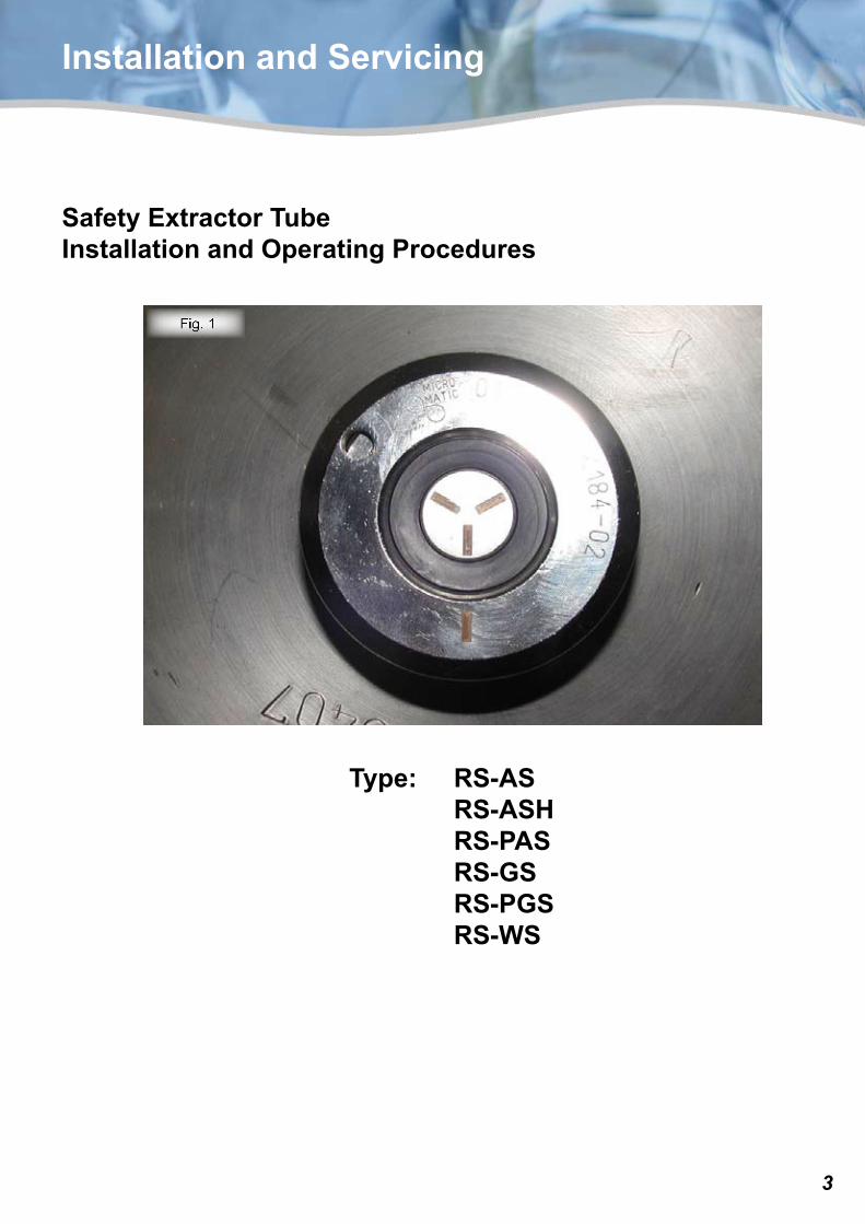
Safety Extractor TubeInstallation and Operating Procedures
Type: RS-AS RS-ASH RS-PAS RS-GS RS-PGS RS-WS
�
1
2
3 4
6
7
5
Fig. 2
Installation and Servicing
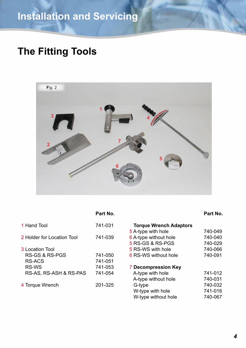
Part No.
1HandTool 741-031
2HolderforLocationTool 741-039
3LocationToolRS-GS&RS-PGS 741-050RS-ACS 741-051RS-WS 741-053RS-AS,RS-ASH&RS-PAS 741-054
4TorqueWrench 201-325
Part No.
Torque Wrench Adaptors5A-typewithhole 740-0496A-typewithouthole 740-0405RS-GS&RS-PGS 740-0295RS-WSwithhole 740-0666RS-WSwithouthole 740-091
7Decompression KeyA-typewithhole 741-012A-typewithouthole 740-031G-type 740-032W-typewithhole 741-016W-typewithouthole 740-067
The Fitting Tools
�
Fig. 3
Installation and Servicing
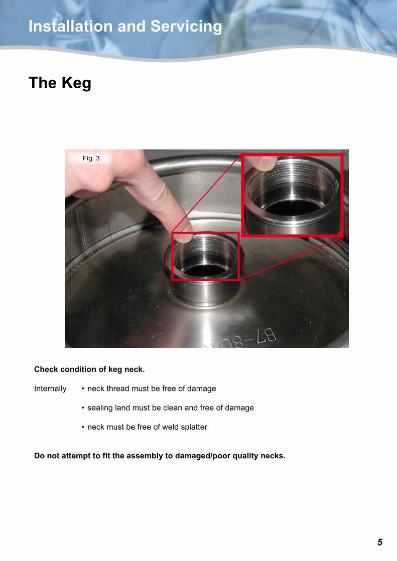
The Keg
Check condition of keg neck.
Internally •neckthreadmustbefreeofdamage
•sealinglandmustbecleanandfreeofdamage
•neckmustbefreeofweldsplatter
Do not attempt to fit the assembly to damaged/poor quality necks.
�
Fig. 4
Fig. 5
Fig. 6
Installation and Servicing
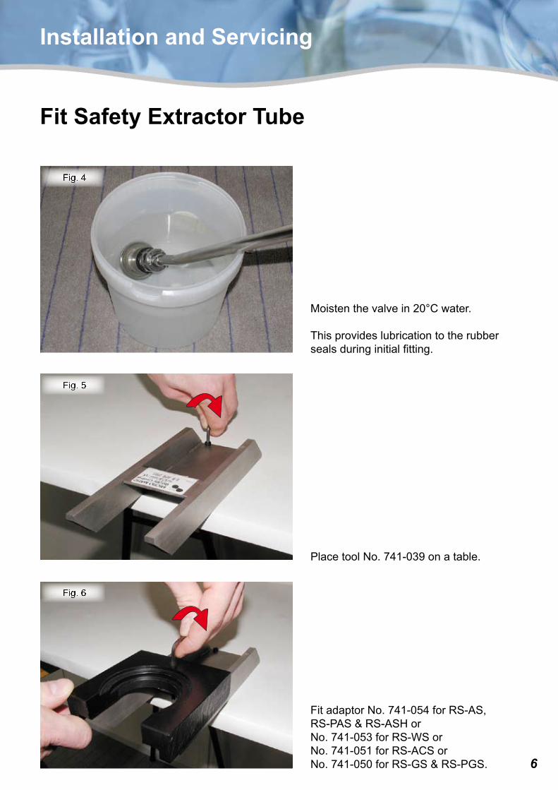
PlacetoolNo.741-039onatable.
Fit Safety Extractor Tube
Moistenthevalvein20°Cwater.
Thisprovideslubricationtotherubbersealsduringinitialfitting.
FitadaptorNo.741-054forRS-AS,RS-PAS&RS-ASHorNo.741-053forRS-WSorNo.741-051forRS-ACSorNo.741-050forRS-GS&RS-PGS.
�
Fig. 9
Fig. 7
Fig. 8
Installation and Servicing
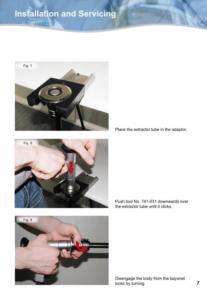
PushtoolNo.741-031downwardsovertheextractortubeuntilitclicks.
Disengagethebodyfromthebayonetlocksbyturning.
Placetheextractortubeintheadaptor.
�
Fig. 12
Fig. 11
Fig. 10
Installation and Servicing
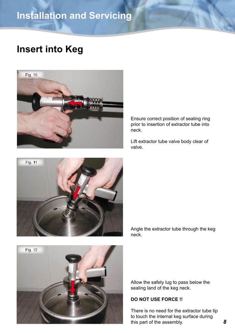
Angletheextractortubethroughthekegneck.
Insert into Keg
Ensurecorrectpositionofsealingringpriortoinsertionofextractortubeintoneck.
Liftextractortubevalvebodyclearofvalve.
Allowthesafetylugtopassbelowthesealinglandofthekegneck.
DO NOT USE FORCE !!
Thereisnoneedfortheextractortubetiptotouchtheinternalkegsurfaceduringthispartoftheassembly.
�
Fig. 15
Fig. 14
Fig. 13
Installation and Servicing
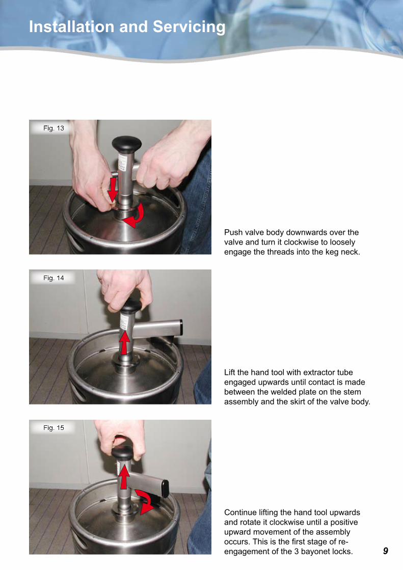
Pushvalvebodydownwardsoverthevalveandturnitclockwisetolooselyengagethethreadsintothekegneck.
Liftthehandtoolwithextractortubeengagedupwardsuntilcontactismadebetweentheweldedplateonthestemassemblyandtheskirtofthevalvebody.
Continueliftingthehandtoolupwardsandrotateitclockwiseuntilapositiveupwardmovementoftheassemblyoccurs.Thisisthefirststageofre-engagementofthe3bayonetlocks.
10
Fig. 18
Fig. 17
Fig. 16
Installation and Servicing
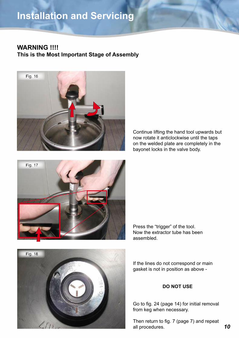
Continueliftingthehandtoolupwardsbutnowrotateitanticlockwiseuntilthetapsontheweldedplatearecompletelyinthebayonetlocksinthevalvebody.
Pressthe“trigger”ofthetool.Nowtheextractortubehasbeenassembled.
WARNING !!!! This is the Most Important Stage of Assembly
Ifthelinesdonotcorrespondormaingasketisnotinpositionasabove-
DO NOT USE
Gotofig.24(page14)forinitialremovalfromkegwhennecessary.
Thenreturntofig.7(page7)andrepeatallprocedures.
11
Fig. 20
Fig. 19
Installation and Servicing
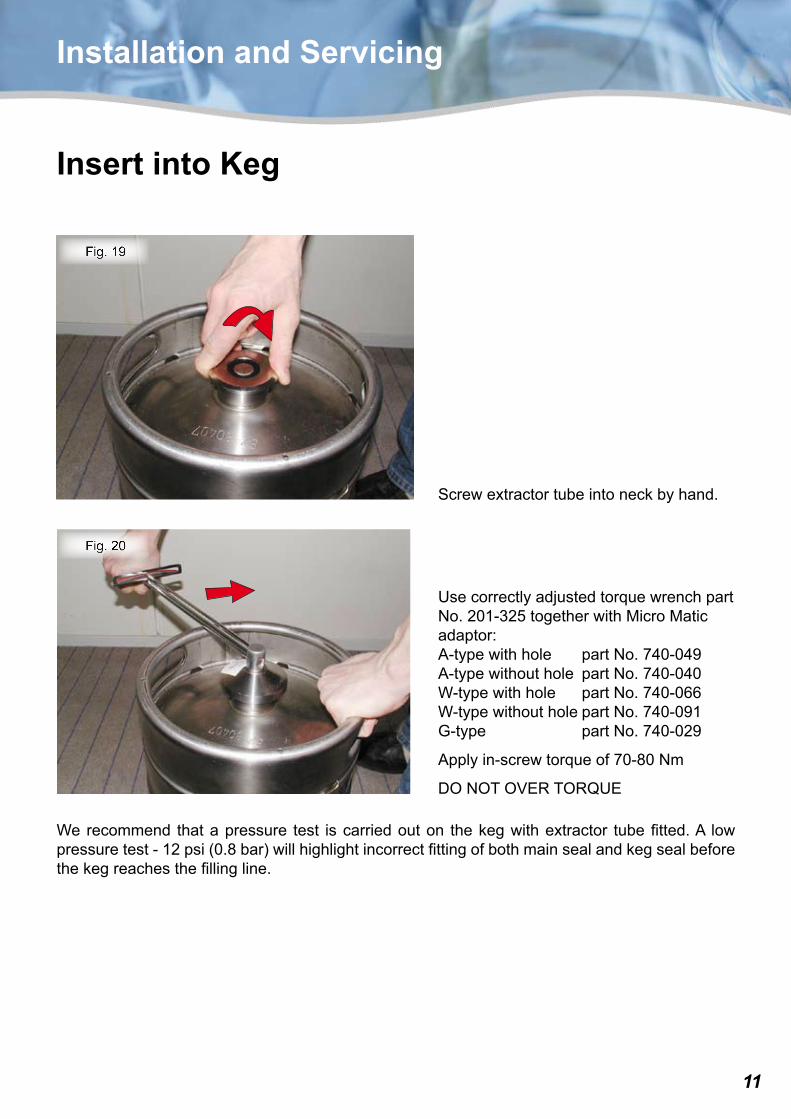
Insert into Keg
Screwextractortubeintoneckbyhand.
UsecorrectlyadjustedtorquewrenchpartNo.201-325togetherwithMicroMaticadaptor:A-typewithhole partNo.740-049A-typewithouthole partNo.740-040W-typewithhole partNo.740-066W-typewithoutholepartNo.740-091G-type partNo.740-029
Applyin-screwtorqueof70-80Nm
DONOTOVERTORQUE
Werecommend thatapressure test iscarriedouton thekegwithextractor tubefitted.A lowpressuretest-12psi(0.8bar)willhighlightincorrectfittingofbothmainsealandkegsealbeforethekegreachesthefillingline.
1�
Fig. 21
Installation and Servicing
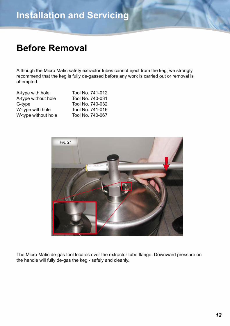
Before Removal
AlthoughtheMicroMaticsafetyextractortubescannotejectfromthekeg,westronglyrecommendthatthekegisfullyde-gassedbeforeanyworkiscarriedoutorremovalisattempted.
A-typewithhole ToolNo.741-012A-typewithouthole ToolNo.740-031G-type ToolNo.740-032W-typewithhole ToolNo.741-016W-typewithouthole ToolNo.740-067
TheMicroMaticde-gastoollocatesovertheextractortubeflange.Downwardpressureonthehandlewillfullyde-gasthekeg-safelyandcleanly.
1�
Fig. 23
Fig. 22
Installation and Servicing
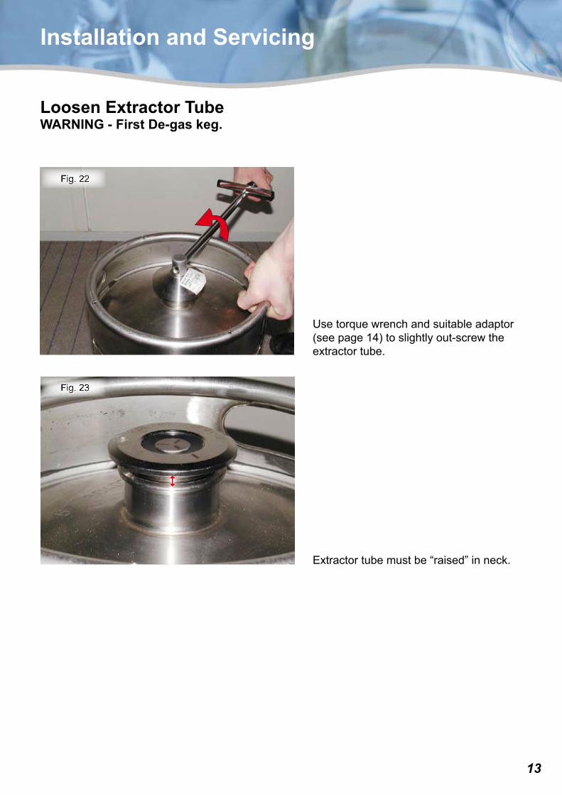
Loosen Extractor TubeWARNING - First De-gas keg.
Usetorquewrenchandsuitableadaptor(seepage14)toslightlyout-screwtheextractortube.
Extractortubemustbe“raised”inneck.
1�
Fig. 26
Fig. 25
Fig. 24
Installation and Servicing
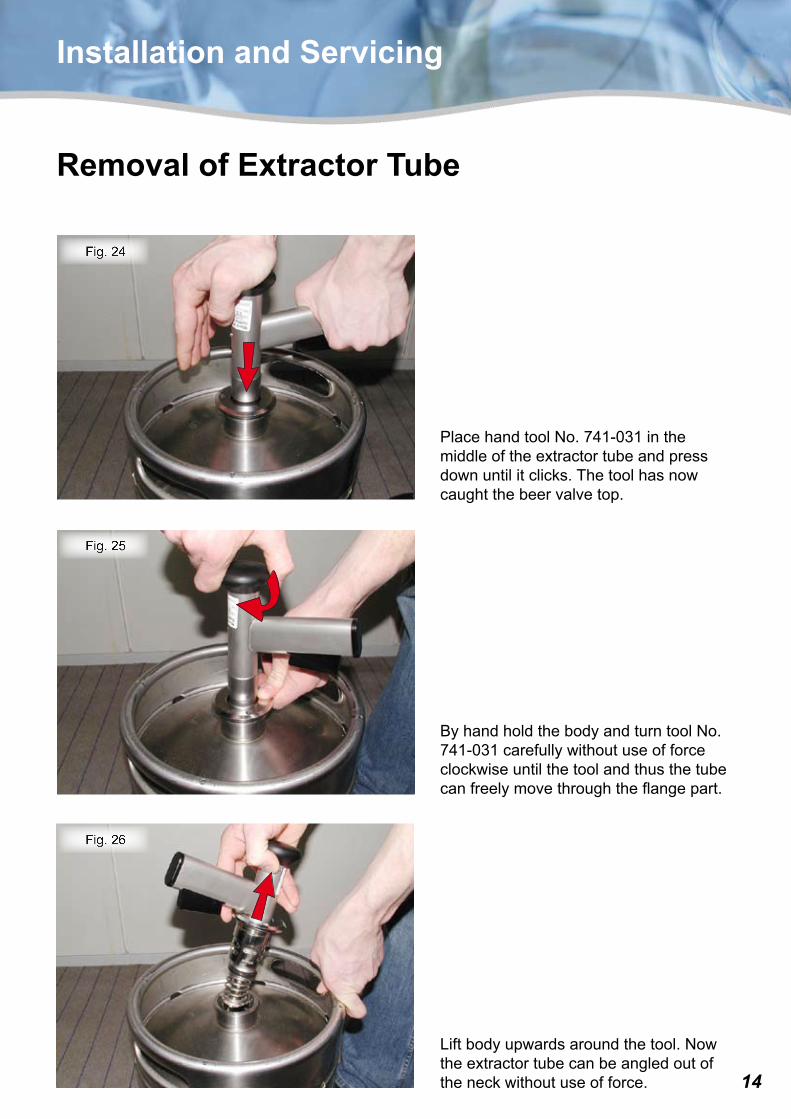
Removal of Extractor Tube
PlacehandtoolNo.741-031inthemiddleoftheextractortubeandpressdownuntilitclicks.Thetoolhasnowcaughtthebeervalvetop.
ByhandholdthebodyandturntoolNo.741-031carefullywithoutuseofforceclockwiseuntilthetoolandthusthetubecanfreelymovethroughtheflangepart.
Liftbodyupwardsaroundthetool.Nowtheextractortubecanbeangledoutoftheneckwithoutuseofforce.
1�
Fig. 27
Installation and Servicing
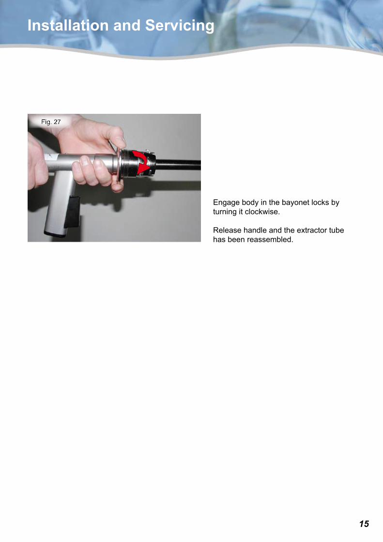
Engagebodyinthebayonetlocksbyturningitclockwise.
Releasehandleandtheextractortubehasbeenreassembled.
1�
Installation and Servicing
Extractor Tube Servicing
ThedesignoftheMicroMaticRS-ASextractortubeallowssimpleonsiteservicing.
Theconstructionisrobustanddurableandunlessdeliberatedamagehasoccurred,theonlyreplaceablepartsaretherubbercomponents.
These rubber parts must be replaced each time an extractor tube is removed from a keg.
1�
Fig. 28
Fig. 29
Fig. 30
Installation and Servicing
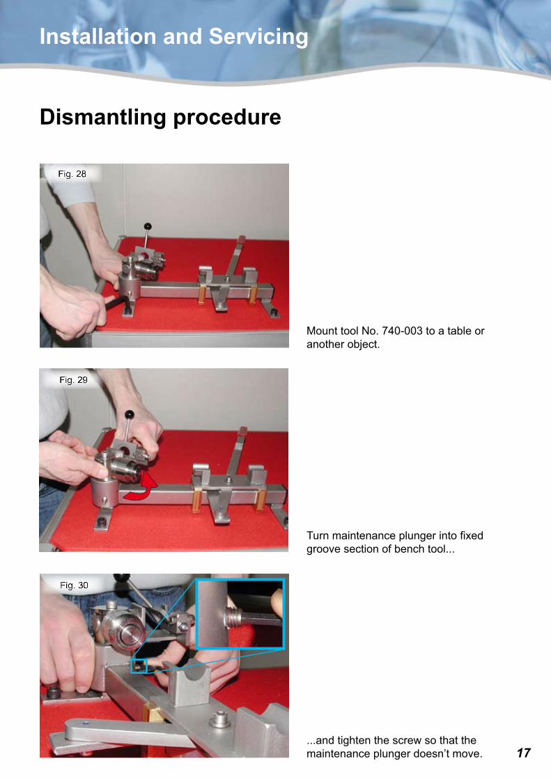
Dismantling procedure
Turnmaintenanceplungerintofixedgroovesectionofbenchtool...
MounttoolNo.740-003toatableoranotherobject.
...andtightenthescrewsothatthemaintenanceplungerdoesn’tmove.
1�
Fig. 33
Fig. 32
Fig. 31
Installation and Servicing
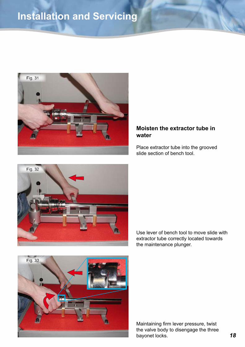
Moisten the extractor tube in water
Placeextractortubeintothegroovedslidesectionofbenchtool.
Useleverofbenchtooltomoveslidewithextractortubecorrectlylocatedtowardsthemaintenanceplunger.
Maintainingfirmleverpressure,twistthevalvebodytodisengagethethreebayonetlocks.
1�
Fig. 36
Fig. 35
Fig. 34
Installation and Servicing
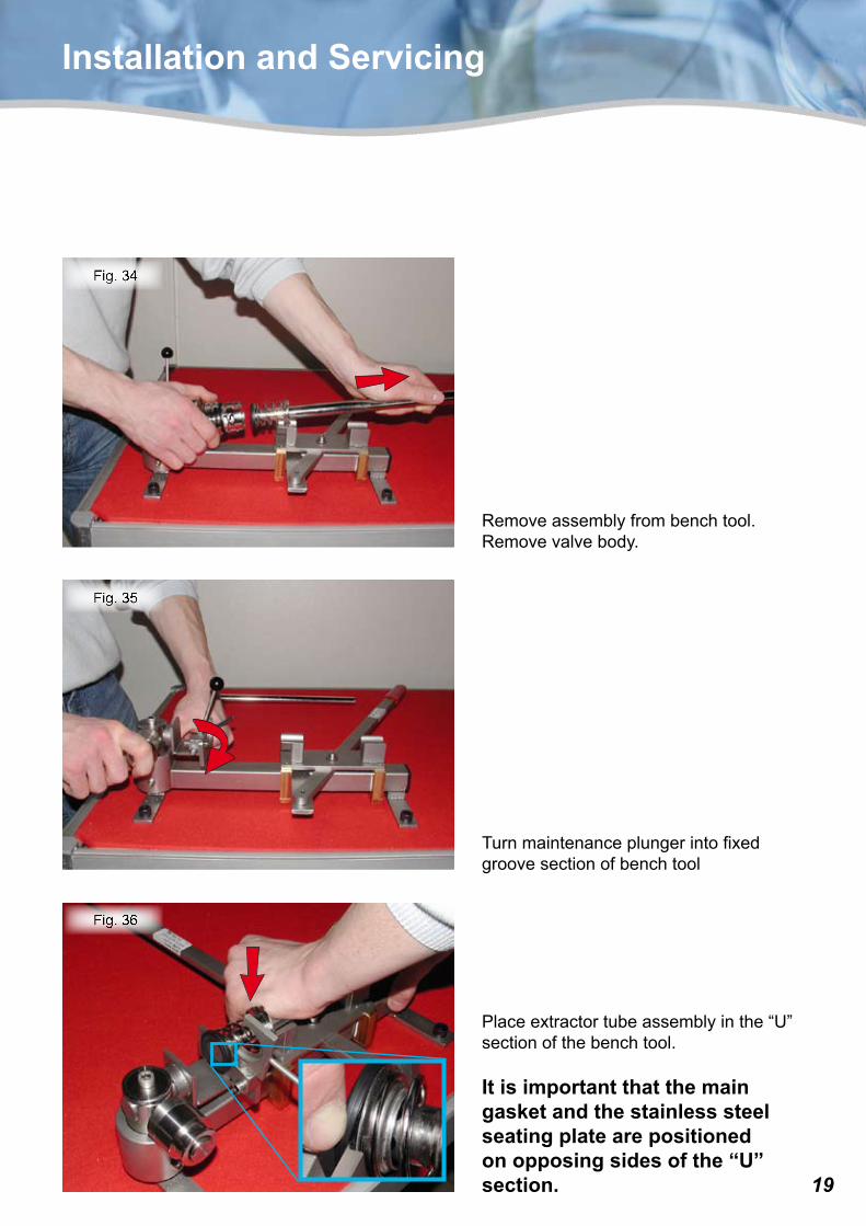
Removeassemblyfrombenchtool.Removevalvebody.
Placeextractortubeassemblyinthe“U”sectionofthebenchtool.
It is important that the main gasket and the stainless steel seating plate are positioned on opposing sides of the “U” section.
Turnmaintenanceplungerintofixedgroovesectionofbenchtool
�0
Fig. 39
Fig. 38
Fig. 37
Installation and Servicing
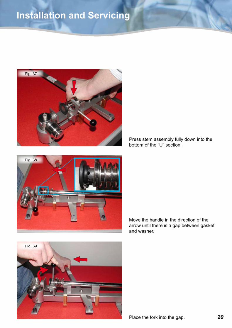
Pressstemassemblyfullydownintothebottomofthe“U”section.
Movethehandleinthedirectionofthearrowuntilthereisagapbetweengasketandwasher.
Placetheforkintothegap.
�1
Fig. 41
Fig. 40
Installation and Servicing
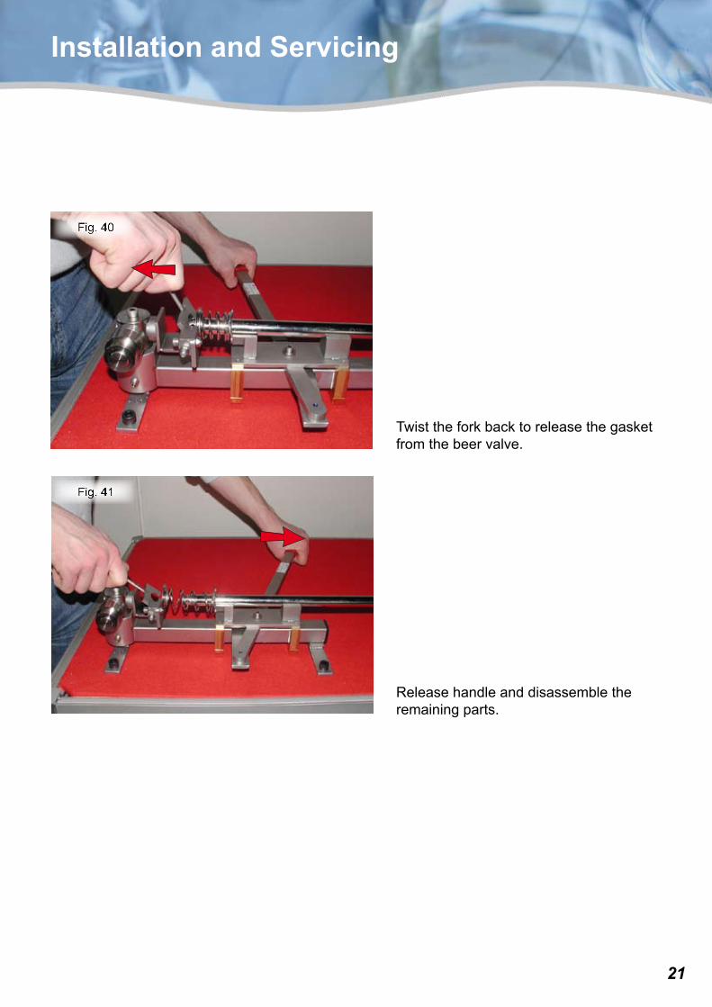
Twisttheforkbacktoreleasethegasketfromthebeervalve.
Releasehandleanddisassembletheremainingparts.
��
Fig. 44
Fig. 43
Fig. 42
Installation and Servicing
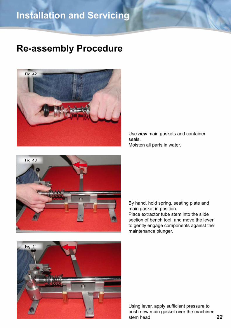
Re-assembly Procedure
Usenewmaingasketsandcontainerseals.Moistenallpartsinwater.
Byhand,holdspring,seatingplateandmaingasketinposition.Placeextractortubestemintotheslidesectionofbenchtool,andmovethelevertogentlyengagecomponentsagainstthemaintenanceplunger.
Usinglever,applysufficientpressuretopushnewmaingasketoverthemachinedstemhead.
��
Fig. 47
Fig. 46
Fig. 45
Installation and Servicing
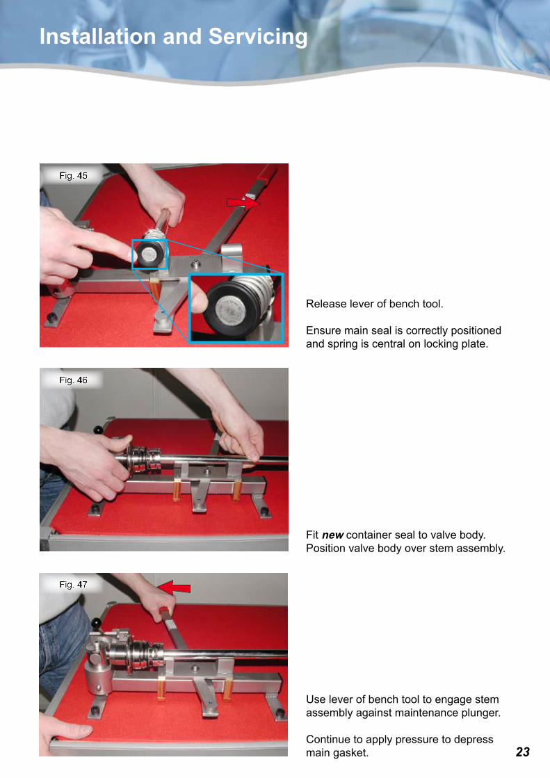
Releaseleverofbenchtool.
Ensuremainsealiscorrectlypositionedandspringiscentralonlockingplate.
Fitnewcontainersealtovalvebody.Positionvalvebodyoverstemassembly.
Useleverofbenchtooltoengagestemassemblyagainstmaintenanceplunger.
Continuetoapplypressuretodepressmaingasket.
��
Fig. 48
Installation and Servicing
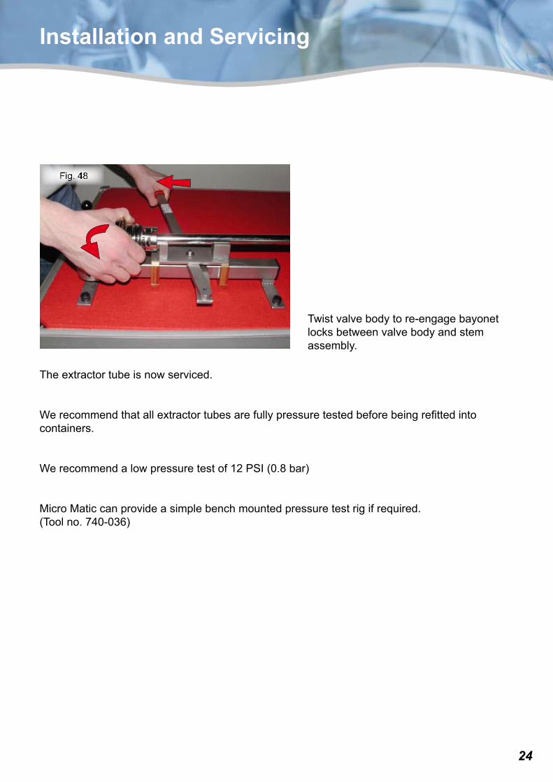
Twistvalvebodytore-engagebayonetlocksbetweenvalvebodyandstemassembly.
Theextractortubeisnowserviced.
Werecommendthatallextractortubesarefullypressuretestedbeforebeingrefittedintocontainers.
Werecommendalowpressuretestof12PSI(0.8bar)
MicroMaticcanprovideasimplebenchmountedpressuretestrigifrequired.(Toolno.740-036)


![Installationsanleitung | Installation instructions ... · [1520]2 × DRN63 /BE, /RS[1907]1 × DRN63 (/BE, /RS) 25898728/DE – 10/2019. EI7C B DRN631 Installationsanleitung | Installation](https://img.pdfslide.us/doc/110x75/605d2cf372a58806557c06c7/installationsanleitung-installation-instructions-15202-drn63-be-rs19071.jpg)