Embed Size (px)
Citation preview


2 Classic LX, RS - Installation
CAUTION. To avoid the possibility of injury during the installation, servicing or cleaning ofthis appliance, care should be taken when handling edges of sheet steel components.
3Classic LX, RS - Installation
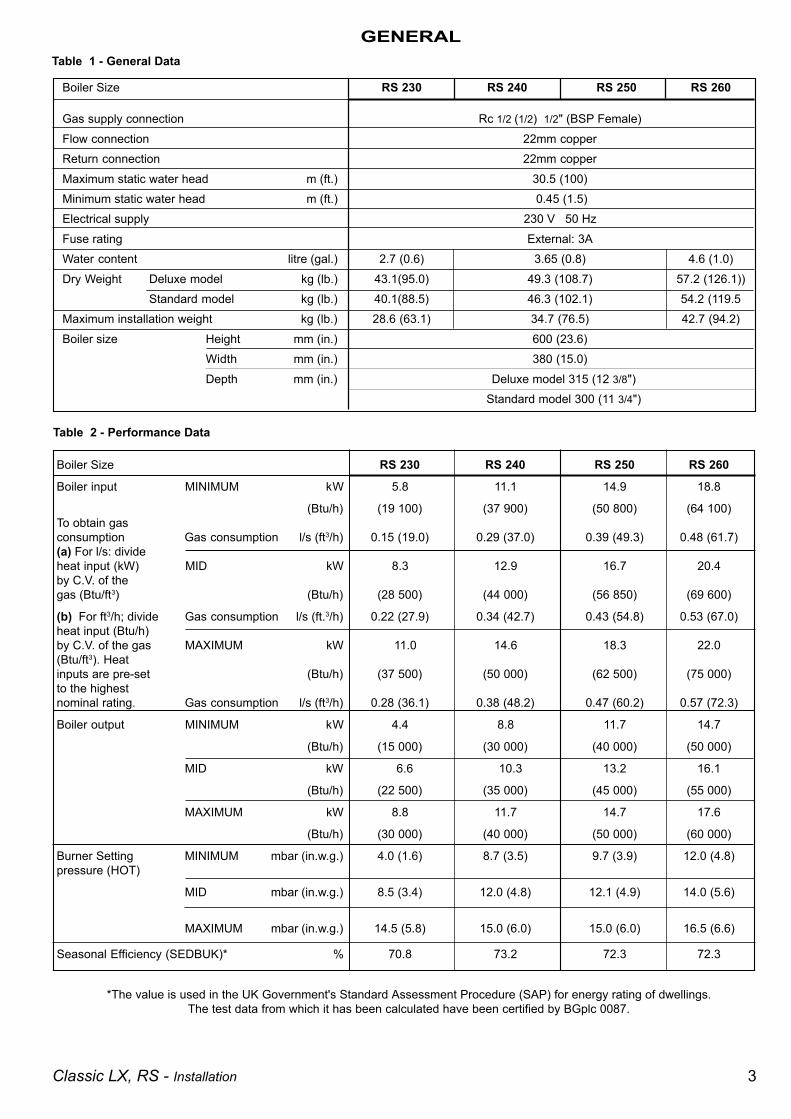
Boiler Size RS 230 RS 240 RS 250 RS 260
Boiler input MINIMUM kW 5.8 11.1 14.9 18.8
(Btu/h) (19 100) (37 900) (50 800) (64 100)To obtain gasconsumption Gas consumption l/s (ft3/h) 0.15 (19.0) 0.29 (37.0) 0.39 (49.3) 0.48 (61.7)(a) For l/s: divideheat input (kW) MID kW 8.3 12.9 16.7 20.4by C.V. of thegas (Btu/ft3) (Btu/h) (28 500) (44 000) (56 850) (69 600)
(b) For ft3/h; divide Gas consumption l/s (ft.3/h) 0.22 (27.9) 0.34 (42.7) 0.43 (54.8) 0.53 (67.0)heat input (Btu/h)by C.V. of the gas MAXIMUM kW 11.0 14.6 18.3 22.0(Btu/ft3). Heatinputs are pre-set (Btu/h) (37 500) (50 000) (62 500) (75 000)to the highestnominal rating. Gas consumption l/s (ft3/h) 0.28 (36.1) 0.38 (48.2) 0.47 (60.2) 0.57 (72.3)
Boiler output MINIMUM kW 4.4 8.8 11.7 14.7
(Btu/h) (15 000) (30 000) (40 000) (50 000)
MID kW 6.6 10.3 13.2 16.1
(Btu/h) (22 500) (35 000) (45 000) (55 000)
MAXIMUM kW 8.8 11.7 14.7 17.6
(Btu/h) (30 000) (40 000) (50 000) (60 000)
Burner Setting MINIMUM mbar (in.w.g.) 4.0 (1.6) 8.7 (3.5) 9.7 (3.9) 12.0 (4.8)pressure (HOT)
MID mbar (in.w.g.) 8.5 (3.4) 12.0 (4.8) 12.1 (4.9) 14.0 (5.6)
MAXIMUM mbar (in.w.g.) 14.5 (5.8) 15.0 (6.0) 15.0 (6.0) 16.5 (6.6)
Seasonal Efficiency (SEDBUK)* % 70.8 73.2 72.3 72.3
Boiler Size RS 230 RS 240 RS 250 RS 260
Gas supply connection Rc 1/2 (1/2) 1/2" (BSP Female)Flow connection 22mm copperReturn connection 22mm copperMaximum static water head m (ft.) 30.5 (100)Minimum static water head m (ft.) 0.45 (1.5)Electrical supply 230 V 50 HzFuse rating External: 3AWater content litre (gal.) 2.7 (0.6) 3.65 (0.8) 4.6 (1.0)Dry Weight Deluxe model kg (lb.) 43.1(95.0) 49.3 (108.7) 57.2 (126.1))
Standard model kg (lb.) 40.1(88.5) 46.3 (102.1) 54.2 (119.5Maximum installation weight kg (lb.) 28.6 (63.1) 34.7 (76.5) 42.7 (94.2)Boiler size Height mm (in.) 600 (23.6)
Width mm (in.) 380 (15.0)Depth mm (in.) Deluxe model 315 (12 3/8")
Standard model 300 (11 3/4")
GENERALTable 1 - General Data
Table 2 - Performance Data
*The value is used in the UK Government's Standard Assessment Procedure (SAP) for energy rating of dwellings.The test data from which it has been calculated have been certified by BGplc 0087.
4 Classic LX, RS - Installation
GENERAL
CONTENTS
Air Supply. ...................................................................... 8
Boiler Assembly - Exploded view ................................ 9
Boiler Clearances .......................................................... 6
Burner Assembly - Exploded view ............................ 27
Electrical Connections ............................................... 15
Electrical Diagram ....................................................... 15
Electrical Supply ........................................................... 8
Extension Ducts - Fitting ............................................ 14
Fault Finding ............................................................... 26
Flue Fitting ................................................................... 14
Flue Installation ............................................................. 7
Gas Safety Regulations ................................................ 5
Gas Supply .................................................................... 7
Health & Safety Document No 635 .............................. 5
Initial Lighting .............................................................. 17
Installation ..................................................................... 9
Mandatory Requirements ............................................. 5
Pump ............................................................................ 11
Servicing ...................................................................... 19
Short List of Parts ....................................................... 27
System Diagrams ........................................................ 16
Terminal Guards. ........................................................... 7
Water and Systems ....................................................... 8
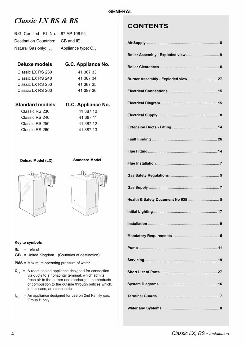
Classic LX RS & RS
Standard ModelDeluxe Model (LX)
Key to symbols
IE = IrelandGB = United Kingdom (Countries of destination)
PMS = Maximum operating pressure of water
C12 = A room sealed appliance designed for connectionvia ducts to a horizontal terminal, which admitsfresh air to the burner and discharges the productsof combustion to the outside through orifices which,in this case, are concentric.
I2H = An appliance designed for use on 2nd Family gas,Group H only.
B.G. Certified - P.I. No. 87 AP 108 94
Destination Countries: GB and IE
Natural Gas only: I2H Appliance type: C12
Deluxe models G.C. Appliance No.Classic LX RS 230 41 387 33Classic LX RS 240 41 387 34Classic LX RS 250 41 387 35Classic LX RS 260 41 387 36
Standard models G.C. Appliance No.Classic RS 230 41 387 10Classic RS 240 41 387 11Classic RS 250 41 387 12Classic RS 260 41 387 13
5Classic LX, RS - Installation
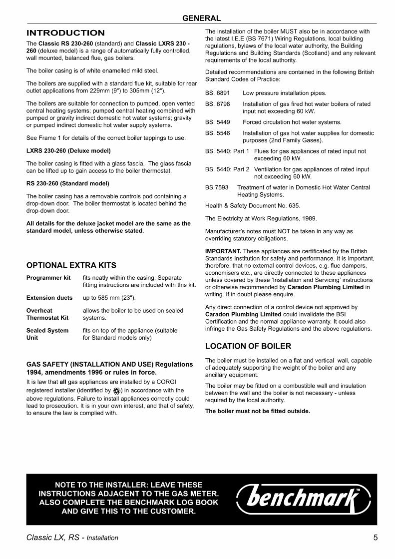
INTRODUCTIONThe Classic RS 230-260 (standard) and Classic LXRS 230 -260 (deluxe model) is a range of automatically fully controlled,wall mounted, balanced flue, gas boilers.
The boiler casing is of white enamelled mild steel.
The boilers are supplied with a standard flue kit, suitable for rearoutlet applications from 229mm (9") to 305mm (12").
The boilers are suitable for connection to pumped, open ventedcentral heating systems; pumped central heating combined withpumped or gravity indirect domestic hot water systems; gravityor pumped indirect domestic hot water supply systems.
See Frame 1 for details of the correct boiler tappings to use.
LXRS 230-260 (Deluxe model)
The boiler casing is fitted with a glass fascia. The glass fasciacan be lifted up to gain access to the boiler thermostat.
RS 230-260 (Standard model)
The boiler casing has a removable controls pod containing adrop-down door. The boiler thermostat is located behind thedrop-down door.
All details for the deluxe jacket model are the same as thestandard model, unless otherwise stated.
OPTIONAL EXTRA KITSProgrammer kit fits neatly within the casing. Separate
fitting instructions are included with this kit.
Extension ducts up to 585 mm (23").
Overheat allows the boiler to be used on sealedThermostat Kit systems.
Sealed System fits on top of the appliance (suitableUnit for Standard models only)
The installation of the boiler MUST also be in accordance withthe latest I.E.E (BS 7671) Wiring Regulations, local buildingregulations, bylaws of the local water authority, the BuildingRegulations and Building Standards (Scotland) and any relevantrequirements of the local authority.
Detailed recommendations are contained in the following BritishStandard Codes of Practice:
BS. 6891 Low pressure installation pipes.
BS. 6798 Installation of gas fired hot water boilers of ratedinput not exceeding 60 kW.
BS. 5449 Forced circulation hot water systems.
BS. 5546 Installation of gas hot water supplies for domesticpurposes (2nd Family Gases).
BS. 5440: Part 1 Flues for gas appliances of rated input notexceeding 60 kW.
BS. 5440: Part 2 Ventilation for gas appliances of rated inputnot exceeding 60 kW.
BS 7593 Treatment of water in Domestic Hot Water CentralHeating Systems.
Health & Safety Document No. 635.
The Electricity at Work Regulations, 1989.
Manufacturer’s notes must NOT be taken in any way asoverriding statutory obligations.
IMPORTANT. These appliances are certificated by the BritishStandards Institution for safety and performance. It is important,therefore, that no external control devices, e.g. flue dampers,economisers etc., are directly connected to these appliancesunless covered by these ‘Installation and Servicing’ instructionsor otherwise recommended by Caradon Plumbing Limited inwriting. If in doubt please enquire.
Any direct connection of a control device not approved byCaradon Plumbing Limited could invalidate the BSICertification and the normal appliance warranty. It could alsoinfringe the Gas Safety Regulations and the above regulations.
LOCATION OF BOILERThe boiler must be installed on a flat and vertical wall, capableof adequately supporting the weight of the boiler and anyancillary equipment.
The boiler may be fitted on a combustible wall and insulationbetween the wall and the boiler is not necessary - unlessrequired by the local authority.
The boiler must not be fitted outside.
GENERAL
NOTE TO THE INSTALLER: LEAVE THESEINSTRUCTIONS ADJACENT TO THE GAS METER.ALSO COMPLETE THE BENCHMARK LOG BOOK
AND GIVE THIS TO THE CUSTOMER.
GAS SAFETY (INSTALLATION AND USE) Regulations1994, amendments 1996 or rules in force.It is law that all gas appliances are installed by a CORGIregistered installer (identified by ) in accordance with theabove regulations. Failure to install appliances correctly couldlead to prosecution. It is in your own interest, and that of safety,to ensure the law is complied with.
6 Classic LX, RS - Installation
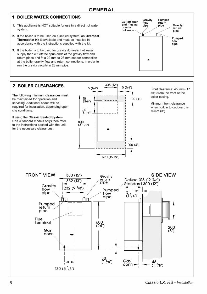
GENERAL1 BOILER WATER CONNECTIONS
2 BOILER CLEARANCES
1. This appliance is NOT suitable for use in a direct hot watersystem.
2. If the boiler is to be used on a sealed system, an OverheatThermostat Kit is available and must be installed inaccordance with the instructions supplied with the kit.
3. If the boiler is to be used for gravity domestic hot watersupply then cut off the spun ends of the gravity flow andreturn pipes and fit a 22 mm to 28 mm copper connectionat the boiler gravity flow and return connections, in order torun the gravity circuits in 28 mm pipe.
Front clearance: 450mm (173/4") from the front of theboiler casing.
Minimum front clearancewhen built in to cupboard is75mm (3")
The following minimum clearances mustbe maintained for operation andservicing. Additional space will berequired for installation, depending uponsite conditions.
If using the Classic Sealed SystemUnit (Standard models only) then referto the instructions packed with the unitfor the necessary clearances..

7Classic LX, RS - Installation
GENERAL
FLUE INSTALLATIONThe flue must be installed in accordance with therecommendations of BS. 5440:1.
The following notes are intended for general guidance:-
1. The boiler MUST be installed so that the terminal is exposedto external air.
2. It is important that the position of the terminal allows the freepassage of air across it at all times.
3. Minimum acceptable spacing from the terminal toobstructions and ventilation openings are specified inTable 3.
Table 3 - Balanced flue terminal position
Timber Framed Buildings
If the boiler is to be fitted in a timber framed building it should befitted in accordance with the Institute of Gas Engineering documentIGE/UP/7:1998.
Bathrooms
The boiler may be installed in any room or internal space, althoughparticular attention is drawn to the requirements of the current I.E.E.(BS 7671) Wiring Regulations and, in Scotland, the electricalprovisions of the building regulations applicable in Scotland withrespect to the installation of the boiler in a room or internal spacecontaining a bath or shower.
Where a room-sealed appliance is installed in a room containinga bath or shower then the appliance and any electrical switch orappliance control utilising mains electricity should be so situatedthat it cannot be touched by a person using the bath or shower.
Where installation will be in an unusual location, special proceduresmay be necessary and BS.6798 gives detailed guidance on thisaspect.
Compartment Installations
A compartment used to enclose the boiler MUST be designedand constructed specially for this purpose.An existing cupboard or compartment may be used, providing it ismodified for the purpose.
In both cases details of essential features of cupboards/compartment design, including airing cupboard installation, are toconform to the following:
BS. 6798.
The position selected for installation MUST allowadequate space for servicing in front of the boilerand for air circulation around the boiler, see section on 'AirSupply'.
For the minimum clearances required for safety, andsubsequent service, see Frame 2. In addition,sufficient boiler clearance may be required to allowlifting access to the wall mounting plate.
GAS SUPPLYThe local gas supplier should be consulted, at the installationplanning stage, in order to establish the availability of an adequatesupply of gas. An existing service pipe must NOT be used withoutprior consultation with the local gas supplier.
A gas meter can only be connected by the local gas supplier or bya local regional contractor.
An existing meter should be checked, preferably by the gassupplier, to ensure that the meter is adequate to deal with the rateof gas supply required. A minimum gas pressure of 20 mbar MUSTbe available at the boiler inlet, with the boiler operating.
Installation pipes MUST be fitted in accordance with BS. 6891.Pipework from the meter to the boiler MUST be of an adequatesize.
The complete installation MUST be tested for gas soundness andpurged as described in the above code.
Terminal Position Minimum Spacing
1. Directly below anopening window, air vent or otherventilation opening 300 mm (12")
2. Below guttering, drain pipes or soilpipes 300 mm (12")
3. Below eaves 300 mm (12")4. Below balconies or a car port roof 600 mm (24")5. From vertical drain pipes or soil pipes 75 mm (3")6. From internal or external corners 600 mm (24")7. Above adjacent ground, roof or
balcony level 300 mm (12")8. From a surface facing the terminal 600 mm (24")9. From a terminal facing a terminal 600 mm (24")10. From an opening in a car port
(e.g. door or window) into dwelling 1200 mm (48")11. Vertically from a terminal on the
same wall 1500 mm (60")
12. Horizontally from a terminal on the wall 300 mm (12")
4. Where the lowest part of the terminal is fitted less than 2m(6' 6") above a balcony, above ground or above a flat roof towhich people have access then the terminal MUST beprotected by a purpose designed guard.
Terminals guards are available from boiler suppliers - ask forTower Flue Guard Model K1. In case of difficulty seekadvice from:
Tower Flue Components Ltd.,Vale Rise, Tonbridge, Kent. TN9 1TB (Model C)Telephone No. 01732 351 555
Ensure that the guard is fitted centrally.
5. Where the terminal is fitted within 1000mm (39 1/2") of aplastic or painted gutter or 500mm (19 1/2") of painted eavesthen an aluminium shield at least 1000mm (39 1/2") longshould be fitted to the underside of the gutter or paintedsurface.
6. The air inlet/products outlet duct and the terminal of theboiler MUST NOT be closer than 25mm (1") to combustiblematerial. Detailed recommendations on the protection ofcombustible material are given in BS.5440: 1990.
8 Classic LX, RS - Installation
GENERALIMPORTANT. It is absolutely ESSENTIAL to ensure, in practice,that products of combustion discharging from the terminalcannot re-enter the building or any other adjacent buildingthrough ventilators, windows, doors, other sources of natural airinfiltration or forced ventilation/air conditioning.
If this should occur, the appliance MUST be turned OFF,labelled 'unsafe' and corrective action taken.
TERMINALThe terminal assembly can be adapted to accommodate variouswall thicknesses. Refer to Frame 4 - Unpacking.
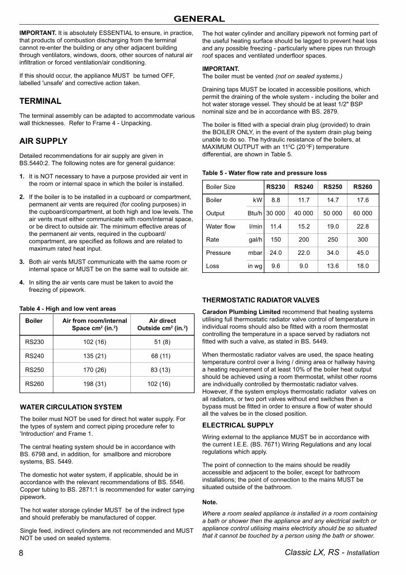
AIR SUPPLYDetailed recommendations for air supply are given inBS.5440:2. The following notes are for general guidance:
1. It is NOT necessary to have a purpose provided air vent inthe room or internal space in which the boiler is installed.
2. If the boiler is to be installed in a cupboard or compartment,permanent air vents are required (for cooling purposes) inthe cupboard/compartment, at both high and low levels. Theair vents must either communicate with room/internal space,or be direct to outside air. The minimum effective areas ofthe permanent air vents, required in the cupboard/compartment, are specified as follows and are related tomaximum rated heat input.
3. Both air vents MUST communicate with the same room orinternal space or MUST be on the same wall to outside air.
4. In siting the air vents care must be taken to avoid thefreezing of pipework.
Table 4 - High and low vent areas
WATER CIRCULATION SYSTEMThe boiler must NOT be used for direct hot water supply. Forthe types of system and correct piping procedure refer to'Introduction' and Frame 1.
The central heating system should be in accordance withBS. 6798 and, in addition, for smallbore and microboresystems, BS. 5449.
The domestic hot water system, if applicable, should be inaccordance with the relevant recommendations of BS. 5546.Copper tubing to BS. 2871:1 is recommended for water carryingpipework.
The hot water storage cylinder MUST be of the indirect typeand should preferably be manufactured of copper.
Single feed, indirect cylinders are not recommended and MUSTNOT be used on sealed systems.
THERMOSTATIC RADIATOR VALVESCaradon Plumbing Limited recommend that heating systemsutilising full thermostatic radiator valve control of temperature inindividual rooms should also be fitted with a room thermostatcontrolling the temperature in a space served by radiators notfitted with such a valve, as stated in BS. 5449.
When thermostatic radiator valves are used, the space heatingtemperature control over a living / dining area or hallway havinga heating requirement of at least 10% of the boiler heat outputshould be achieved using a room thermostat, whilst other roomsare individually controlled by thermostatic radiator valves.However, if the system employs thermostatic radiator valves onall radiators, or two port valves without end switches then abypass must be fitted in order to ensure a flow of water shouldall the valves be in the closed position.
ELECTRICAL SUPPLYWiring external to the appliance MUST be in accordance withthe current I.E.E. (BS. 7671) Wiring Regulations and any localregulations which apply.
The point of connection to the mains should be readilyaccessible and adjacent to the boiler, except for bathroominstallations; the point of connection to the mains MUST besituated outside of the bathroom.
Note.
Where a room sealed appliance is installed in a room containinga bath or shower then the appliance and any electrical switch orappliance control utilising mains electricity should be so situatedthat it cannot be touched by a person using the bath or shower.
The hot water cylinder and ancillary pipework not forming part ofthe useful heating surface should be lagged to prevent heat lossand any possible freezing - particularly where pipes run throughroof spaces and ventilated underfloor spaces.
IMPORTANT.The boiler must be vented (not on sealed systems.)
Draining taps MUST be located in accessible positions, whichpermit the draining of the whole system - including the boiler andhot water storage vessel. They should be at least 1/2" BSPnominal size and be in accordance with BS. 2879.
The boiler is fitted with a special drain plug (provided) to drainthe BOILER ONLY, in the event of the system drain plug beingunable to do so. The hydraulic resistance of the boilers, atMAXIMUM OUTPUT with an 110C (20 0F) temperaturedifferential, are shown in Table 5.
Table 5 - Water flow rate and pressure loss
Boiler Size RS230 RS240 RS250 RS260
Boiler kW 8.8 11.7 14.7 17.6
Output Btu/h 30 000 40 000 50 000 60 000
Water flow l/min 11.4 15.2 19.0 22.8
Rate gal/h 150 200 250 300
Pressure mbar 24.0 22.0 34.0 45.0
Loss in wg 9.6 9.0 13.6 18.0
Boiler Air from room/internal Air directSpace cm2 (in.2) Outside cm2 (in.2)
RS230 102 (16) 51 (8)
RS240 135 (21) 68 (11)
RS250 170 (26) 83 (13)
RS260 198 (31) 102 (16)
9Classic LX, RS - Installation
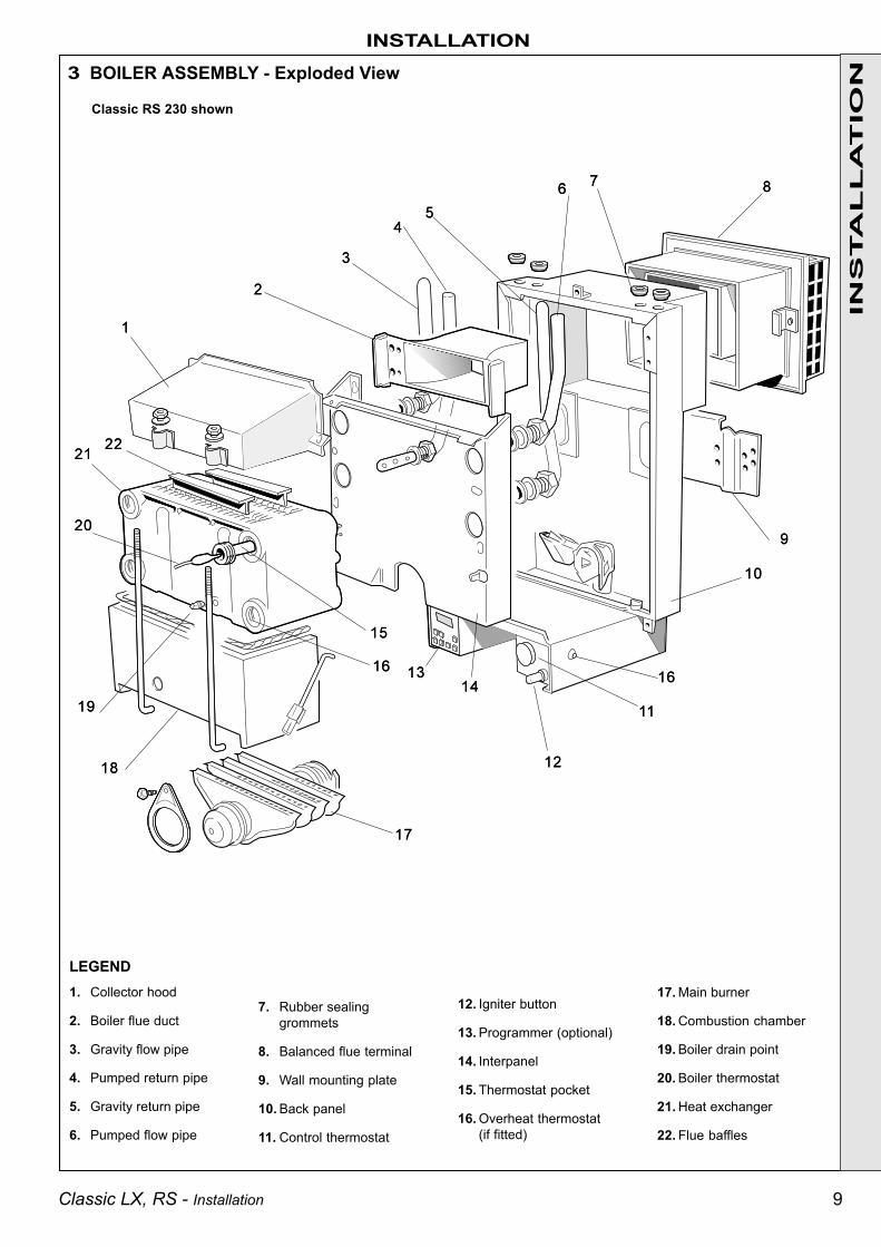
Classic RS 230 shown
3 BOILER ASSEMBLY - Exploded View
7. Rubber sealinggrommets
8. Balanced flue terminal
9. Wall mounting plate
10. Back panel
11. Control thermostat
12. Igniter button
13. Programmer (optional)
14. Interpanel
15. Thermostat pocket
16. Overheat thermostat(if fitted)
17. Main burner
18. Combustion chamber
19. Boiler drain point
20. Boiler thermostat
21. Heat exchanger
22. Flue baffles
INS
TA
LL
AT
ION
INSTALLATION
LEGEND1. Collector hood
2. Boiler flue duct
3. Gravity flow pipe
4. Pumped return pipe
5. Gravity return pipe
6. Pumped flow pipe
10 Classic LX, RS - Installation
INSTALLATIONIN
STA
LL
AT
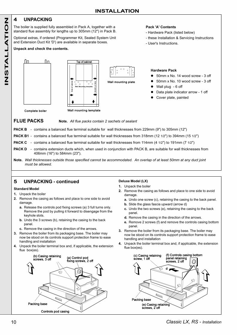
ION 4 UNPACKING
The boiler is supplied fully assembled in Pack A, together with astandard flue assembly for lengths up to 305mm (12") in Pack B.
Optional extras, if ordered (Programmer Kit, Sealed System Unitand Extension Duct Kit 'D') are available in separate boxes.
Unpack and check the contents.
FLUE PACKS Note. All flue packs contain 2 sachets of sealant
PACK B - contains a balanced flue terminal suitable for wall thicknesses from 229mm (9") to 305mm (12")
PACK B1 - contains a balanced flue terminal suitable for wall thicknesses from 318mm (12 1/2") to 394mm (15 1/2")
PACK C - contains a balanced flue terminal suitable for wall thicknesses from 114mm (4 1/2") to 191mm (7 1/2")
PACK D - contains extension ducts which, when used in conjunction with PACK B, are suitable for wall thicknesses from406mm (16") to 584mm (23").
Note. Wall thicknesses outside those specified cannot be accommodated. An overlap of at least 50mm at any duct jointmust be allowed.
Hardware Pack50mm x No. 14 wood screw - 3 off50mm x No. 10 wood screw - 3 offWall plug - 6 offData plate indicator arrow - 1 offCover plate, painted
5 UNPACKING - continuedStandard Model1. Unpack the boiler2. Remove the casing as follows and place to one side to avoid
damage.a. Release the controls pod fixing screws (a) 3 full turns only.
Remove the pod by pulling it forward to disengage from thekeyhole slots.
b. Undo the 3 screws (b), retaining the casing to the backpanel.
c. Remove the casing in the direction of the arrows.3. Remove the boiler from its packaging base. The boiler may
now be stood on its controls support protection frame to easehandling and installation
4. Unpack the boiler terminal box and, if applicable, the extensionflue box(es).
Deluxe Model (LX)1. Unpack the boiler2. Remove the casing as follows and place to one side to avoid
damage.a. Undo one screw (c), retaining the casing to the back panel.b. Slide the glass fascia upward (arrow d)c. Undo the two screws (e), retaining the casing to the back
panel.d. Remove the casing in the direction of the arrows.e. Remove 2 screws (f) and remove the controls casing bottom
panel.3. Remove the boiler from its packaging base. The boiler may
now be stood on its controls support protection frame to easehandling and installation
4. Unpack the boiler terminal box and, if applicable, the extensionflue box(es).
Pack 'A' Contents- Hardware Pack (listed below)- these Installation & Servicing Instructions- User's Instructions.

11Classic LX, RS - Installation
INSTALLATION
Note. The pumpmanufacturers minimumrequirements must becomplied with.
All dimensions in mm (in.)
NOTE. Gravity horizontal pipes should be ABOVE ceiling level and as SHORT aspossible. A MINIMUM inclination of 25mm per 3m run (1" per 10') is required to avoidair locks. If these conditions cannot be met, pumped primaries MUST be used.
NB: Imperial dimensions are approximate
The above graph assumes 8 elbows in the gravity circuit. For each elbow in excessof 8, (R) must be reduced by 300 mm (12 in.) or (H) increased by 100 mm (4 in.)
6 OPEN VENT SYSTEM REQUIREMENTS - Fully pumpedThe system should be vented directly off the boiler flow pipe, as close tothe boiler as possible. The cold feed entry should be inverted and MUST bepositioned between the pump and the vent, and not more than 150mm (6")away from the vent connection.There should be a minimum height - 450mm (18") of open vent above thecistern water level. If this is impossible refer below.The vertical distance between the highest point of the system and the feed/expansion cistern water level MUST not be less than 450mm (18").The pump MUST be fitted on the flow side of the boiler.A suitable pump is a domestic circulator capable of providing an 11°C(20°F) temperature differential (e.g. Grunfos UPS 15/50 or equivalent). Thevertical distance between the pump and feed/expansion cistern MUSTcomply with the pump manufacturer's minimum requirements to avoidcavitation. Should these conditions not apply, either lower the pumpposition or raise the cistern above the minimum requirement specified byCaradon Plumbing Limited.
Note. A cold water feed must be available back to the boiler when allautomatic valves are in the closed position (refer to BS. 6798) and, whenclose coupled, the feed must not be in a vertical leg.
System return
Connections to boiler Inverted cold
feed entry
System flow to pump
150 (6")Max
15mmCold feed
450 (18")Mimimum
450 (18")Mimimum
22mmOpen vent
Feed / expansion cistern
Water level(cold)
INS
TA
LL
AT
ION
Minimum Requirements
Surge arrester
75 (3)Min.
450(18)Min. 200
(8)Min.
Highest point of flow or return
150(6)
Max
Max. practical length
To pump
Coldwater level
Feed / expansioncistern
75 (3) Min.
FlowReturn22 (3/4)
Open vent
7 LOW HEAD INSTALLATIONSThe Classic range of boilers can be installed in lowhead situations by fitting a 'surge arrester' in theexpansion pipe, as shown.
The following conditions MUST be observed:
1. The surge arrester must be at least 42mm indiameter x 150mm long, thus ensuring a MINIMUMair gap and a MINIMUM depth of water below thestatic water level (cold) of 75mm.
2. The static water level (cold) must be at least 200mmabove the top of the horizontal flow pipe, fitted asshown. The vent connection MUST NOT be madeimmediately off the top of the boiler, as venting ismade less efficient.
3. The maximum practical length of 15mm cold feedpipe should be used in order to reduce the effectivevolume of system water expanding into the feed/expansion cistern to a minimum.
8 REQUIREMENTS FOR CORRECT GRAVITY HOT WATER PERFORMANCE

12 Classic LX, RS - Installation
INSTALLATION
1. Tape the template to the wall in the selected position.Ensure squareness by use of a plumbline, as shown.
2. Mark out the position of the 3 wallplate screws, choosingone from each group of 3 holes. Also mark the position ofthe hole for the duct, the jacking screw and the top coverplate screws.
3. Drill the 3 holes, 8 mm (5/16" ), and insert the 3 plasticplugs. Drill the jacking screw and the top cover platescrew holes 7mm (9/32") and insert the plastic plugs.
4. Remove the template from the wall.
IMPORTANT.The wall must be of suitable load bearing capacity.
1. Cut the appropriate hole in the wall for insertionof the terminal assembly.
Note. The terminal must not come into contactwith a combustible material such as that usedin the non-standard construction of timberframework and plasterboard etc.
2. Fix the mounting plate to the wall with the 3No.14 x 50 mm screws provided.
Check the jacking screw is fitted and screwed home.
INS
TA
LL
AT
ION
10 PREPARING THE WALL
11 CHECKING THE BOILER
9 WALL MOUNTING TEMPLATE
Rear View of Boiler

13Classic LX, RS - Installation
INS
TA
LL
AT
IONFlue Alignment
It ismostimportantthat theboiler isinstalledin theverticalposition
The wall must be of suitable load-bearing capacity
1. Lift the boiler onto the wall mounting plate,entering the projecting flue duct into the openingcut in the wall, and lowering the 2 slots in theboiler back panel onto the angled tabs on thetop of the wall mounting plate.
DO NOT USE THE BURNER ASSEMBLY FORLIFTING.
2. Adjust the flue to its horizontal position by tiltingthe boiler forward at the bottom then turning thejacking screw. Release and check alignment witha spirit level. Secure the jacking screw with aNo.10 x 50 mm wood screw.
3. Fit the top cover plate in position above theboiler air duct with the 2 No.10 x 50 mm screwsprovided.
INSTALLATION
Do NOT use the burner assembly for lifting
12 MOUNTING THE BOILER
14 Classic LX, RS - Installation
A. Air duct joint
B. Flue duct joint
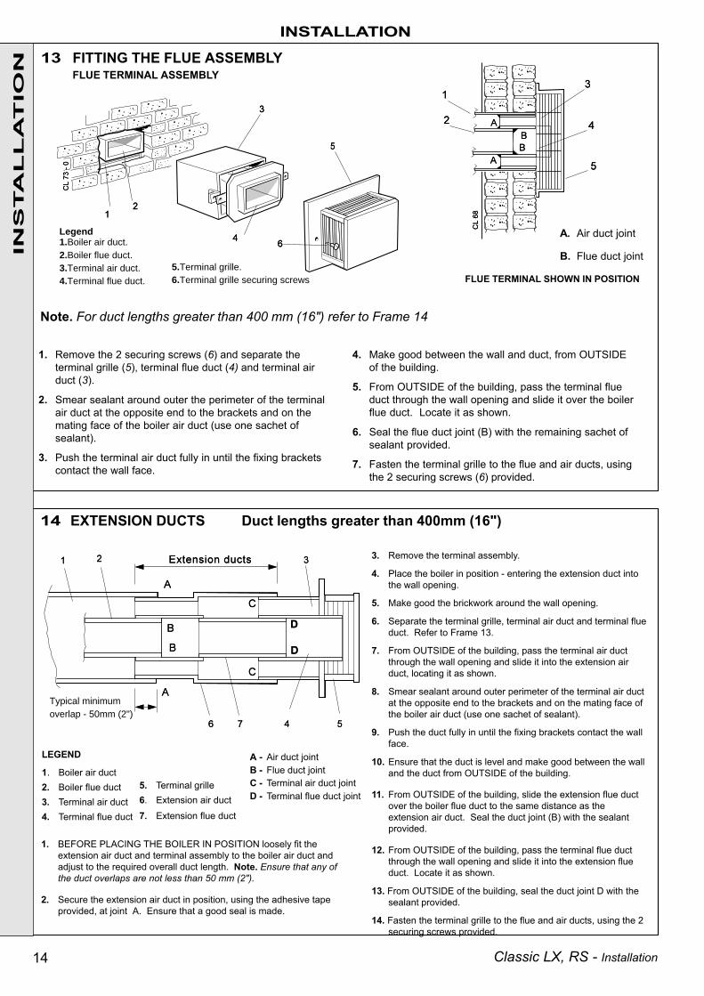
LEGEND
1. Boiler air duct2. Boiler flue duct3. Terminal air duct4. Terminal flue duct
5. Terminal grille6. Extension air duct7. Extension flue duct
1. BEFORE PLACING THE BOILER IN POSITION loosely fit theextension air duct and terminal assembly to the boiler air duct andadjust to the required overall duct length. Note. Ensure that any ofthe duct overlaps are not less than 50 mm (2").
2. Secure the extension air duct in position, using the adhesive tapeprovided, at joint A. Ensure that a good seal is made.
FLUE TERMINAL SHOWN IN POSITION
Note. For duct lengths greater than 400 mm (16") refer to Frame 14
A - Air duct jointB - Flue duct jointC - Terminal air duct jointD - Terminal flue duct joint
14 EXTENSION DUCTS Duct lengths greater than 400mm (16")
1. Remove the 2 securing screws (6) and separate theterminal grille (5), terminal flue duct (4) and terminal airduct (3).
2. Smear sealant around outer the perimeter of the terminalair duct at the opposite end to the brackets and on themating face of the boiler air duct (use one sachet ofsealant).
3. Push the terminal air duct fully in until the fixing bracketscontact the wall face.
4. Make good between the wall and duct, from OUTSIDEof the building.
5. From OUTSIDE of the building, pass the terminal flueduct through the wall opening and slide it over the boilerflue duct. Locate it as shown.
6. Seal the flue duct joint (B) with the remaining sachet ofsealant provided.
7. Fasten the terminal grille to the flue and air ducts, usingthe 2 securing screws (6) provided.
5.Terminal grille.6.Terminal grille securing screws
Legend1.Boiler air duct.2.Boiler flue duct.3.Terminal air duct.4.Terminal flue duct.
INS
TA
LL
AT
ION 13 FITTING THE FLUE ASSEMBLY
Typical minimum overlap - 50mm (2")
INSTALLATION
FLUE TERMINAL ASSEMBLY
3. Remove the terminal assembly.
4. Place the boiler in position - entering the extension duct intothe wall opening.
5. Make good the brickwork around the wall opening.
6. Separate the terminal grille, terminal air duct and terminal flueduct. Refer to Frame 13.
7. From OUTSIDE of the building, pass the terminal air ductthrough the wall opening and slide it into the extension airduct, locating it as shown.
8. Smear sealant around outer perimeter of the terminal air ductat the opposite end to the brackets and on the mating face ofthe boiler air duct (use one sachet of sealant).
9. Push the duct fully in until the fixing brackets contact the wallface.
10. Ensure that the duct is level and make good between the walland the duct from OUTSIDE of the building.
11. From OUTSIDE of the building, slide the extension flue ductover the boiler flue duct to the same distance as theextension air duct. Seal the duct joint (B) with the sealantprovided.
12. From OUTSIDE of the building, pass the terminal flue ductthrough the wall opening and slide it into the extension flueduct. Locate it as shown.
13. From OUTSIDE of the building, seal the duct joint D with thesealant provided.
14. Fasten the terminal grille to the flue and air ducts, using the 2securing screws provided.

15Classic LX, RS - Installation
The internal wiring of the control box is shown in Frame 19.
DETAIL OF CONTROL BOX TERMINALS
Note. In order to connect the incoming mains wires, first remove thecontrol box fixing screw then pull the boxforward and downward to disengage.
Ensure that the earth lead is longer than thelive and neutral so that if the cable slips inits anchorage the current conductorsbecome taut before the earth conductor andthat the cable is routed through the strainrelief clamp. Ensure all cables are secureand that no basic insulation is accessibleoutside of the control box.
15 GAS CONNECTIONA MINIMUM gas pressure of 20 mbar (8 in.w.g.) MUST beavailable at the boiler inlet, with the boiler operating.
The main gas cock is on the left hand side of the gas controlvalve, as shown.
To facilitate connection the gas cock may removed from the gascontrol valve.
16 WATER CONNECTIONS
1. Remove the plastic plugs from the flow and returnpipes.
2. Make all water connections and check for watersoundness.
LEGEND
b blue br brown g/y green/yellow
INSTALLATION
INS
TA
LL
AT
ION
WARNING. The appliance MUST be efficiently earthed.
A mains supply of 230 V ~ 50 Hz is required.
All external controls and wiring MUST be suitable for mainsvoltage. Wiring should be in 3-core PVC insulated cable NOTLESS than 0.75 mm2 (24 x 0.2 mm) to BS.6500, Table 16.
Wiring external to the boiler MUST be in accordance with currentl.E.E. (BS7671) Wiring Regulations and local regulations.
Connection must be made in a way that allows complete isolationof the electrical supply - such as a double pole switch, having a3mm (1/8") contact separation in both poles, or a plug and socketserving only the boiler and system controls. The means ofisolation must be accessible to the user after installation.
Note. If the optional Programmer Kit is to be fitted, refer tothe instructions provided with the kit, ignore this frame and goto Frame 18.
The wiring diagrams illustrated in Frames 20-23 cover the systemsmost likely to be fitted to this appliance.
For wiring external controls to the Classic RS boiler, referenceshould be made to the system wiring diagrams supplied by therelevant manufacturer, in conjunction with the wiring diagrams shownin Frames 19-23.
Difficulty in wiring should not arise, providing the following directionsare observed:
1. Controls that switch the system ON and OFF, e.g. a time switch,MUST be wired, in series, in the live mains lead to the boiler.
2. Controls that override an ON/OFF control, e.g. a frost thermostat,MUST be wired into the mains lead, in parallel, with the control(s)to be overridden - refer to Frame 23.
3. Controls that switch the circulation pump only ON and OFF, e.g. aroom thermostat, MUST be wired in series with the pump in thelive pump lead.
4. If a proprietary system is used, follow the instructions supplied bythe manufacturer.
5. SYSTEM DESIGNS FEATURING CONTROLS OR WIRINGARRANGEMENTS WHICH ALLOW THE BOILER TO FIRE WHENTHERE IS NO PUMPED OR GRAVITY CIRCULATION TAKING PLACESHOULD NOT BE FITTED.
Advice on required modifications to the wiring may be obtained fromthe component manufacturers.
Notes 1. Connections between a frost thermostat and the timecontrol should be made without disturbing other
wiring.2. A frost thermostat should be sited in a cool place in
the house, but where it can sense heat from the system.
19 PICTORIAL WIRING
FLOW WIRING DIAGRAM
18 EXTERNAL CONTROLS
17 ELECTRICAL CONNECTIONS

16 Classic LX, RS - Installation
Notes. Pumped only1. Some earth wires are omitted for clarity. Ensure proper earth
continuity when wiring.2. Numbering of terminals on thermostats is specific to the
manufacturer.3. This is a fully controlled system - set the boiler thermostat to
maximum.4. Switchmaster 'Midi' is similar in operation but the wiring differs
slightly; see manufacturer's literature.
22 HONEYWELL 'C' PLANNotes. Gravity HW & Pumped CH1. Some earth wires are omitted for clarity. Ensure proper earth
continuity when wiring
2. Numbering of terminals on thermostats is specific to themanufacturer.
23 FROST PROTECTION
INSTALLATIONIN
STA
LL
AT
ION 21 TWO SPRING CLOSED VALVES
Notes. Pumped only1. Some earth wires are omitted for clarity. Ensure proper earth
continuity when wiring.2. Numbering of terminals on thermostats is specific to the
manufacturer.3. This is a fully controlled system - set the boiler thermostat to
maximum.4. Switchmaster valve has grey and orange auxiliary switch leads but
the grey wire must be connected to the live supply.
Central heating systems fitted wholly inside the house do not normallyrequire frost protection as the house acts as a 'storage heater' and cannormally be left at least 24 hrs. without frost damage. However, if partsof the pipework run outside the house or if the boiler will be left off formore than a day or so, then a frost 'stat should be wired into the system.
This is usually done at the programmer, in which case the programmeselector switches are set to 'Off' and all other controls MUST be left inthe running position. The frost 'stat should be sited in a cold place butwhere it can sense heat from the system. Wiring should be as shown,with minimal disturbance to other wiring of the programmer.
Designation of the terminals will vary, but the programmer and thermostatmanufacturer's leaflets will give full details. Diagram A shows a doublepole frost 'stat, which should suffice for all systems which do not usethe 'OFF' terminals of the programmer. Diagram B shows a 'change-over' frost 'stat, which will cover most systems which do use 'CH OFF.'If, however, on such a system the HW pipework is in an isolated part ofthe house, a second frost 'stat may be used to protect it. If in doubt,ask your installer for advice.
b bluegy greyg/y green/yellow
LEGENDb bluebk black
w whitegy greyg/y green/yellow
br brownr redor orange
LEGENDb bluebk black
g/y green/yellowgy grey
br brownr red
w whiteor orange
20 MID POSITION VALVE
LEGENDw whiter red
bk blackbr brownor orange

17Classic LX, RS - Installation
INS
TA
LL
AT
ION24 COMMISSIONING AND TESTING
A. ELECTRICAL INSTALLATION
1. Checks to ensure electrical safety should be carriedout by a competent person.
2. ALWAYS carry out preliminary electrical systemchecks, i.e. earth continuity, polarity, resistance toearth and short circuit using a suitable test meter.
3. Refit the control box.
B. GAS INSTALLATION1. The whole of the gas installation, including the meter,
MUST be inspected and tested for soundness, andpurged in accordance with the recommendations ofBS. 6891.
2. Purging air from the gas installation may be expedited byloosening the union on the gas service cock on the boilerand purging until gas is detected.
3. Retighten the union and check for gas soundness.
INSTALLATION
E Burner pressure test pointF Main burner pressure adjusterG Inlet pressure test pointH Gas service cock
WARNING. Whilst effecting the required gas soundness test and purging air from the gas installation,open all windows and doors, extinguish naked lights and DO NOT SMOKE.
25 INITIAL LIGHTING
LEGENDA Gas valve control knobB SightglassC Thermostat knobD Piezo unit ignition
1. Check that all drain cocks are CLOSED and any valves inthe flow and return lines are OPEN.
Determine the required heat input and fix the adhesive arrow(supplied in the Hardware Pack) to the data plate on thecontrol support frame, indicating the intended burner settingpressure and heat input.
2. Check that the gas service cock (H) is OPEN and that theboiler thermostat control knob (C) is OFF.
Deluxe Model (LX) - Fit the boiler casing but do not fit thecontrols casing bottom panel (Frame 26).
Standard Model - Fit the boiler casing but do not fit thecontrols casing pod (Frame 26).
3. Loosen the screw in the burner pressure test point (E) andconnect a gas pressure gauge via a flexible tube.
4. Turn the gas control knob clockwise until resistance is feltand then release. WAIT FOR 3 MINUTES.
5. Push in and retain fully depressed the gas control knob (A).Press and release the piezo unit button (D) repeatedly untilthe pilot is seen to light through the sightglass (B).
6. Hold the gas control knob depressed for 15 seconds afterthe pilot burner has ignited, then release.
7. If the pilot burner fails to remain alight at this stage, repeatthe procedure detailed above but wait longer than 15seconds before releasing the gas control knob.
8. Check the appearance of the pilot flame to ensure that itenvelops the tip of the thermocouple and is approximately25mm (1") long. The pilot flame is factory set and noadjustment is possible. If the pilot flame is incorrect refer toFrame 35 .
9. Check that the electricity supply and all external controlsare ON.
10. Set the boiler thermostat control knob to position 6 and checkthat the burner cross-lights smoothly from the pilot flame.
11. Test for gas soundness around the boiler gas componentjoints, using leak detection fluid.
12. Operate the boiler for 10 minutes to stabilise the burnertemperature.
13. Check the burner setting pressure against the relevant valuesquoted in Table 2, Page 3.
14. If the burner setting pressure requires adjustment, removethe silver threaded protection cap on the top of the regulator.Adjust the main burner pressure adjuster (F) until the requiredmain burner pressure is achieved.
15. Set the boiler thermostat control knob to OFF. Remove thepressure gauge tube and tighten the sealing screw in thepressure test point. Relight and check for gas soundness atthe pressure test point.
16. Deluxe Model (LX) - Refit the controls casing bottom paneland screws.
Standard Model - Refit the controls pod and tighten thefront fixing screws.
17. Deluxe Model (LX) - Lower the glass fascia to its closedposition.Standard Model - Close the pod door.

18 Classic LX, RS - Installation
INSTALLATIONIN
STA
LL
AT
ION
Advise the User of the precautions necessary to prevent damageto the system and to the building, in the event of the systemremaining inoperative during frosty conditions.
5. Explain the function and the use of the boiler thermostat andexternal controls.
6. Explain the function of the boiler overheat thermostat (if fitted) andemphasise that if cutout persists, the boiler should be turned offand a CORGI registered installer consulted.
7. Explain and demonstrate the function of time and temperaturecontrols, radiator valves etc., for the economic use of the system.
8. If any Programmer Kit is fitted, then draw attention to theProgrammer Kit User's Instructions and hand them to theHouseholder.
9. After installation, commissioning and customer hand-overinstructions please complete the appliance logbook and leave this with the customer.
10. Stress the importance of regular servicing by a CORGI registeredinstaller and that a comprehensive service should be carried outAT LEAST ONCE A YEAR.
After completing the installation and commissioning of the system theinstaller should hand over to the householder by the following actions:
1. Check that the sealing strip is inplace along the 4 rear edges of theboiler casing.
2. Lift the boiler casing up to the boilerassembly, locate over the uppersupport bracket and secure with the3 captive screws.
3. The casing must be sealed correctly.This MUST be checked by ensuringthat, at the top and bottom edges ofthe casing, the seal is compressedover its complete length.
28 HANDING OVER
1. Hand the User's Instructions to the householder and explainhis or her responsibilities under the Gas Safety (Installationand Use) Regulations 1994, amendments 1996 or rules in force.
2. Deluxe Model (LX) - Draw attention to the lighting instructionlabel affixed to the controls casing bottom panel.
Standard Model - Draw attention to the lighting instruction labelaffixed to the controls pod door.
3. Explain and demonstrate the lighting and shutting downprocedures.
4. The operation of the boiler and the use and adjustment of ALLsystem controls should be fully explained to the Householder,to ensure the greatest possible fuel economy, consistent withhousehold requirements of both heating and hot waterconsumption.
26 FITTING THE CASING
WARNING. The boiler MUST NOT be operated with the casing removed.
Knob Setting Flow TemperatureoC oF
1 56 1332 61 1423 66 1524 72 1615 77 1706 82 180
4. The correct operation of ANY programmer and all othersystem controls should be proved. Operate each controlseparately and check that the main burner or circulatingpump, as the case may be, responds.
5. With the system HOT, examine all water connections forsoundness. Then turn OFF the gas, electricity and watersupplies to the appliance and drain down whilst the systemis still hot, in order to complete the flushing process. Refilland vent the system and again check for water soundness.
6. Finally, set the controls to the user's requirements.
The temperatures quoted below are approximate and varybetween installations.
Make the following checks for correct operation:
1. Turn the boiler thermostat OFF and ON and check that themain burner is extinguished and relit in response.
2. Flame failure device
Check the operation of the flame failure device in the gascontrol valve, as follows:
a. Extinguish the pilot flame by closing the gas servicecock (H) and note the time taken for the flame failuredevice to shut down - identified by a click within the gascontrol valve.
b. Open the gas service cock and relight the pilot.
3. With the burner alight again, turn the gas control knob clockwiseuntil resistance is felt and then release it. The burner and pilotflame should shut down immediately.
Note. A latch in the gas control provides a safety delay periodbefore the pilot can be relit.
27 GENERAL CHECKS
Deluxe Model (LX)Standard Model

19Classic LX, RS - Installation
29 SCHEDULE
SERVICING
SE
RV
ICIN
G
To ensure the continued safe and efficient operation of theappliance, it is recommended that it is checked at regularintervals and serviced as necessary. The frequency of servicingwill depend upon the installation condition and usage but shouldbe carried out at least annually .
It is the law that any service work must be carried out by a CORGIregistered installer.
a. Light the boiler and carry out a pre-service check, notingany operational faults.
b. Clean the main burner.
c. Clean the heat exchanger.
d. Clean the main and pilot injectors.
e. Remove any debris from inside the base of the casing.
30 BOILER CASING REMOVAL
f. Check that the flue terminal is unobstructed and that the fluesystem is sealed correctly.
g. If the appliance has been installed in a compartment, checkthat the ventilation areas are clear.
The servicing procedures are covered more fully in Frames 30to 35 and MUST be carried out in sequence.
WARNING. Disconnect the electrical supply.
IMPORTANT. After completing the servicing or exchange ofcomponents always test for gas soundness and carry outfunctional checks as appropriate.
When work is complete the casing MUST be correctly refitted,ensuring that a good seal is made.
The boiler must NOT be operated if the casing is not fitted.
Note. In order to carry out either servicing or replacement ofcomponents, the boiler casing must be removed (Frame 30).
Deluxe model (LX)Standard model
31 BURNER AND AIR BOX REMOVAL
1. Remove the screw retaining the burner support bracket to thecombustion chamber.
2. Remove the M5 pozi screw situated at the left hand, bottom rearof the burner and pull the burner downwards in order todisengage the retention tab. Remove burner to a safe place forinspection and cleaning.
3. Unscrew the thermocouple connection at the gas control.
4. Remove the 4 screws retaining the air box / pilot assembly to thevertical manifold.
5. Remove the control box fixing screw and pull the box forward anddownward to disengage.
6. Pull off the electrode lead at the piezo unit.
7. Open the clips retaining the thermocouple and HT lead. Removethe air box assembly to a safe place for inspection and cleaning.
1. If the Classic Sealed System Unit (standard modelsonly) is fitted lift off the casing to expose the boilercasing top fixing screw.
2. Deluxe Model (LX) - Release the top captive casingscrew. Lift the glass fascia and pull the sliding catchout, to retain the glass in the upper position. Releasethe lower 2 captive casing screws. Lift the casing offthe boiler and retain in a safe place.
Standard Model - Open the controls pod door andrelease the 3 captive screws at the top and bottom ofthe casing. Lift the casing off the boiler and retain in asafe place.
3. Release the 3 captive screws at the top and bottom ofthe casing. Lift the casing off the boiler and retain in asafe place .
4. Isolate the gas supply at the service cock. Refer toFrame 36.
20 Classic LX, RS - Installation
SERVICINGS
ER
VIC
ING
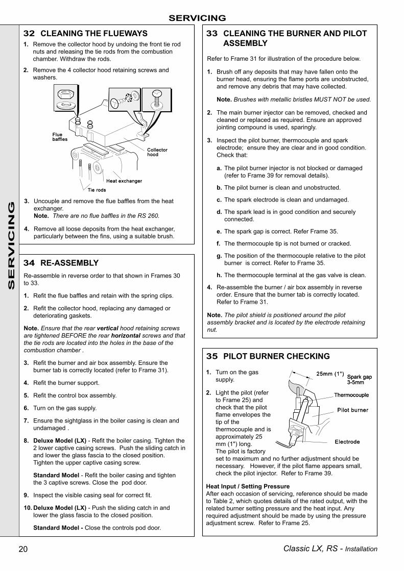
1. Turn on the gassupply.
2. Light the pilot (referto Frame 25) andcheck that the pilotflame envelopes thetip of thethermocouple and isapproximately 25mm (1") long.The pilot is factoryset to maximum and no further adjustment should benecessary. However, if the pilot flame appears small,check the pilot injector. Refer to Frame 39.
Heat Input / Setting PressureAfter each occasion of servicing, reference should be madeto Table 2, which quotes details of the rated output, with therelated burner setting pressure and the heat input. Anyrequired adjustment should be made by using the pressureadjustment screw. Refer to Frame 25.
Re-assemble in reverse order to that shown in Frames 30to 33.
1. Refit the flue baffles and retain with the spring clips.
2. Refit the collector hood, replacing any damaged ordeteriorating gaskets.
Note. Ensure that the rear vertical hood retaining screwsare tightened BEFORE the rear horizontal screws and thatthe tie rods are located into the holes in the base of thecombustion chamber .
3. Refit the burner and air box assembly. Ensure theburner tab is correctly located (refer to Frame 31).
4. Refit the burner support.
5. Refit the control box assembly.
6. Turn on the gas supply.
7. Ensure the sightglass in the boiler casing is clean andundamaged .
8. Deluxe Model (LX) - Refit the boiler casing. Tighten the2 lower captive casing screws. Push the sliding catch inand lower the glass fascia to the closed position.Tighten the upper captive casing screw.
Standard Model - Refit the boiler casing and tightenthe 3 captive screws. Close the pod door.
9. Inspect the visible casing seal for correct fit.
10. Deluxe Model (LX) - Push the sliding catch in andlower the glass fascia to the closed position.
Standard Model - Close the controls pod door.
34 RE-ASSEMBLY
33 CLEANING THE BURNER AND PILOTASSEMBLY
Refer to Frame 31 for illustration of the procedure below.
1. Brush off any deposits that may have fallen onto theburner head, ensuring the flame ports are unobstructed,and remove any debris that may have collected.
Note. Brushes with metallic bristles MUST NOT be used.
2. The main burner injector can be removed, checked andcleaned or replaced as required. Ensure an approvedjointing compound is used, sparingly.
3. Inspect the pilot burner, thermocouple and sparkelectrode; ensure they are clear and in good condition.Check that:
a. The pilot burner injector is not blocked or damaged(refer to Frame 39 for removal details).
b. The pilot burner is clean and unobstructed.
c. The spark electrode is clean and undamaged.
d. The spark lead is in good condition and securelyconnected.
e. The spark gap is correct. Refer Frame 35.
f. The thermocouple tip is not burned or cracked.
g. The position of the thermocouple relative to the pilotburner is correct. Refer to Frame 35.
h. The thermocouple terminal at the gas valve is clean.
4. Re-assemble the burner / air box assembly in reverseorder. Ensure that the burner tab is correctly located.Refer to Frame 31.
Note. The pilot shield is positioned around the pilotassembly bracket and is located by the electrode retainingnut.
35 PILOT BURNER CHECKING
1. Remove the collector hood by undoing the front tie rodnuts and releasing the tie rods from the combustionchamber. Withdraw the rods.
2. Remove the 4 collector hood retaining screws andwashers.
32 CLEANING THE FLUEWAYS
3. Uncouple and remove the flue baffles from the heatexchanger.Note. There are no flue baffles in the RS 260.
4. Remove all loose deposits from the heat exchanger,particularly between the fins, using a suitable brush.

21Classic LX, RS - Installation
REPLACEMENT OF PARTS
1. Refer to Frame 36.
2. Unfasten the 2 nuts and washers holding thesightglass assembly to the casing front panel.
3. When fixing the new assembly, make certain thatthe parts are in the correct order. The frameMUST have the return edge at the bottom.
4. Retighten the 2 nuts to ensure an airtightseal. Do NOT overtighten.
5. Replace the boiler casing.
1. Refer to Frame 36.
2. Remove the control box fixing screw. Pull the box forwardand downward to disengage.
3. Disconnect the ignition lead from the piezo unit.
4. Unscrew the locking nut at the rear of the piezo unitmounting bracket.
5. Remove the piezo unit. Refit the new unit and re-assemblein reverse order.
6. Refit the control box assembly.
7. Replace the boiler casing.
8. Check the operation of the new piezo unit.
SERVICING
When replacing any component:
1. Isolate the electricity supply.
2. Turn off the gas supply at the boiler - refer to theillustration below. Note. The gas cock is shown in theCLOSED position.
3. Remove the boiler casing (refer to Frame 30).
IMPORTANT. When work is complete the casing MUST becorrectly refitted - ensuring that a good seal is made.
38 PIEZO UNIT REPLACEMENTS
ER
VIC
ING
The boiler MUST NOT be operated if the casing is not fitted.
Note. Standard model illustrated.
For the Deluxe model (LX), slide the glass fascia out BEFORE removing thesightglass assembly. Refit the glass fascia AFTER fitting the new sightglassassembly.
37 SIGHTGLASS REPLACEMENT
36 GENERAL

22 Classic LX, RS - Installation
SERVICINGS
ER
VIC
ING
1. Refer to Frame 36.
2. Remove burner andair box assembly.Refer to Frame 31.
3. Remove theelectrode retainingnut. Remove the pilotshield and electrode.
4. Unscrew the central pilot fixing screw and lift the pilotburner clear of the thermocouple and pilot injector.
If required, the pilot injector may now be unscrewed andthe injector checked or replaced as necessary.
Ensure that the copper sealing washer is fitted whenreplacing the injector.
40 SUPPRESSOR REPLACEMENT (IF FITTED)1. Refer to Frame 36.
2. Remove the control box fixing screw. Pull the box forwardand downward to disengage.
3. Remove the suppressor by unscrewing the suppressorlead connections from the terminal block.
4. Fit the new suppressor and re-assemble in reverse order.Ensure that all of the electrical connections are correctlyremade - refer to 'Wiring Diagrams', Frames 19 - 23.
5. Refit the control box.
6. Replace the boiler casing.
7. Check the operation of the control thermostat.
41 CONTROL THERMOSTAT REPLACEMENT1. Refer to Frame 36.
2. Unclip the thermostatcapillary from the clipssituated on the back panel.
3. Remove the thermostatphial from the pocket inthe heat exchanger.
4. Pull off the thermostatknob.
6. Remove the 2 screws securing the thermostat.7. Pull off the 2 electrical connections from the
thermostat head and the thermostat earth lead.8. Fit the new thermostat and refit in reverse order.
Ensure that the phial is correctly replaced in thepocket and the capillary routed as previously.
9. Replace the boiler casing.10. Check the operation of the new thermostat.
Refer to Frame 27.
39 PILOT BURNER REPLACEMENT
5. Replace the pilotburner and retainwith the M4 screwpreviouslyremoved.
6. Replace theelectrode and pilotshield - retainingboth with theelectrode nut.
7. Replace the airbox assembly and ensure that the gasket isin position.
8. Replace the burner.
9. Replace the boiler casing.
10. Check the pilot length. Refer to Frame 35.
11. Check the pilot operation, ignition and cross-lighting.
5. Remove thecontrol boxfixing screwand pull thebox forwardand downwardto disengage.
Detail of thermostatpocket
23Classic LX, RS - Installation
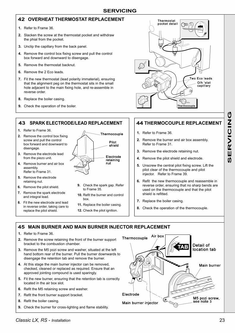
1. Refer to Frame 36.2. Remove the screw retaining the front of the burner support
bracket to the combustion chamber.3. Remove the M5 pozi screw and washer, situated at the left
hand bottom rear of the burner. Pull the burner downwards todisengage the retention tab and remove the burner.
4. At this stage the main burner injector can be removed,checked, cleaned or replaced as required. Ensure that anapproved jointing compound is used sparingly.
5. Fit the new burner, ensuring that the retention tab is correctlylocated in the air box slot.
6. Refit the M5 retaining screw and washer.7. Refit the front burner support bracket.8. Refit the boiler casing.
9. Check the burner for cross-lighting and flame stability.
SERVICING
1. Refer to Frame 36.
2. Remove the burner and air box assembly.Refer to Frame 31.
3. Remove the electrode retaining nut.
4. Remove the pilot shield and electrode.
5. Unscrew the central pilot fixing screw. Lift thepilot clear of the thermocouple and pilotinjector. Refer to Frame 39.
6. Refit the new thermocouple and reassemble inreverse order, ensuring that no sharp bends areused on the thermocouple and that the pilotshield is refitted.
7. Replace the boiler casing.
8. Check the operation of the thermocouple.
SE
RV
ICIN
G
42 OVERHEAT THERMOSTAT REPLACEMENT1. Refer to Frame 36.
2. Slacken the screw at the thermostat pocket and withdrawthe phial from the pocket.
3. Unclip the capillary from the back panel.
4. Remove the control box fixing screw and pull the controlbox forward and downward to disengage.
5. Remove the thermostat backnut.
6. Remove the 2 Eco leads.
7. Fit the new thermostat (lead polarity immaterial), ensuringthat the alignment peg on the thermostat sits in the smallhole adjacent to the main fixing hole, and re-assemble inreverse order.
8. Replace the boiler casing.
9. Check the operation of the boiler.
45 MAIN BURNER AND MAIN BURNER INJECTOR REPLACEMENT
1. Refer to Frame 36.
2. Remove the control box fixingscrew and pull the controlbox forward and downward todisengage.
3. Remove the electrode leadfrom the piezo unit.
4. Remove burner and air boxassembly.Refer to Frame 31.
5. Remove the electroderetaining nut.
6. Remove the pilot shield.
7. Remove the spark electrodeand integral lead.
8. Fit the new electrode and leadin reverse order, taking care toreplace the pilot shield.
9. Check the spark gap. Referto Frame 35.
10. Refit the burner and controlbox.
11. Replace the boiler casing.
12. Check the pilot ignition.
44 THERMOCOUPLE REPLACEMENT43 SPARK ELECTRODE/LEAD REPLACEMENT

24 Classic LX, RS - Installation
SERVICING
Note. Refer also to Frame 54 'Exploded Views' forillustration of the procedure detailed below.
Detail of boiler combustion chamber
SE
RV
ICIN
G
46 GAS CONTROL VALVE REPLACEMENT1. Refer to Frame 36.2. Remove the burner support bracket, burner and air box
assembly. Refer to Frame 31.3. Remove the gas control valve cover and remove the electrical
connections.4. Disconnect the thermocouple from the gas control valve.5. Disconnect and remove the gas union from the control valve.6. Whilst supporting the gas control valve, remove the 2
screws retaining the manifold to the back panel.7. Remove the gas control / manifold assembly.8. Remove the 4 screws retaining the manifold to the gas control
valve and fit the new manifold to the gas control valve,ensuring that it is fitted the correct way round (an arrowengraved on the back indicates the direction of flow).Note. Remove the thermocouple reroute and gas cock stuband refit into the new gas control valve. Use an approvedjointing compound on the pipe stub.
9. Re-assemble in reverse order.10. Replace the boiler casing.11. Check the gas valve operation.
47 COMBUSTION CHAMBER INSULATION REPLACEMENT
48 HEAT EXCHANGER REPLACEMENT 8. Unclip the thermostat capillary and remove the phial from thepocket. Refer to Frame 41.
9. Slacken 3 turns only the 4 screws retaining the heat exchanger /interpanel assembly.
10. Lift the heat exchanger / inter-panel assembly upwards andforwards to disengage the keyhole fixings. Pull the assemblydownwards to clear the water pipes from the back panel.
11. Remove the 4 rubber grommets from the top of the back panel,to facilitate the fitting of the new heat exchanger.
12. Fit the new heat exchanger assembly, complete with its 4 pipeconnections and hang the 4 keyhole slots over the screws.Retighten the 4 screws.
13. Replace the 4 rubber grommets in order to seal the gap betweenthe water pipes and the back panel.
14. Re-assemble in reverse order.
15. Remake all water connections.
16. Fully test all functions, including water and gas soundness.
1. Refer to Frame 36.
2. Drain the system.
3. Remove the burner and air box assembly. Refer to Frame 31.
4. Disconnect the water flow and return connections. Ifcompression fittings are used, cut the pipes both above andbelow the fittings in order to allow the heat exchangerassembly to be removed.Remove the heat exchanger drain plug and drain the residualwater into a suitable receptacle.
5. Remove the collector hood. Refer to Frame 32.
6. Remove the 4 screws retaining the flue duct and remove the duct.
7. Remove the combustion chamber by unscrewing the 4 tie rods.
Note. Refer to Frame 54 of 'Exploded Views' for illustration of theprocedure detailed below:
1. Refer to Frame 36.
2. Remove the burner and air boxassembly. Refer to Frame 31.
3. Remove the 4 tie rods.
4. Remove the combustion chamber.
5. Remove the 2 side panel retainingbrackets.
6. Remove the side insulation panels.
7. Remove the front and rearinsulation panels.
8. Fit the new front and rearinsulation panels.
9. Fit the new side panels andretain with the brackets andscrews previously removed.
10. Re-assemble in reverseorder.

25Classic LX, RS - Installation
SERVICING
1. Refer to Frame 36.
2. Remove the programmer box fixing screw. Pullthe box forward and downward to disengage.
3. Pull the programmer forward out of its box.
4. Pull off the spade connectors.
5. Fit the new programmer and re-assemble inreverse order.
6. Refit the boiler casing.
7. Set the programmer to the desired programmeand check the operation of the boiler.
1. Refer to Frame 36.
2. Remove the old seal from the casing surround.
3. Thoroughly clean the casing surfaces and fit theadhesive seals.
4. Replace the boiler casing.
Detail of programmer
SE
RV
ICIN
G
49 CASING SEAL REPLACEMENT
Note. The standard model is illustrated here.Use the same procedure for the casing sealreplacement on the deluxe model (LX)
Inner view of boiler casing
50 PROGRAMMER REPLACEMENT (if fitted)

26 Classic LX, RS - Installation
NO
NO
NO
Is there a spark at the ignition electrode ?
Is there gas at the pilot burner when the gas valvebutton is pressed ?
Light the pilot burner with a match.Confirm satisfactory ignition, using the piezo unit
51 PILOT WILL NOT LIGHT
Check thermocouple output (8-15 mV closed circuit).Replace thermocouple if output is outside the statedrange. Does the pilot now stay alight ?
Is the connection between the thermocouple andthe gas valve clean and tight ?
YES
Check the pilot injector. Refer to Frame 39Is the pilot flame the correct size (refer to Frame 35) ? NO
Allow time to purge any air present.Check the following; the gas valve button is beingpressed fully in; there is gas pressure at the boilerinlet; the boiler union gas cock is open; the pilot jet
is not blocked
Check the gap between the electrode and the pilotburner; 3-4 mm. Refer to Frame 35.Check the H/T lead and electrode are undamaged andthe connections are NOT close to earthed metalwork.Check the piezo unit is operative - by holding an earthedscrewdriver approximately 3 mm from the H/T outputterminal (with the ignition lead removed) and by operatingthe button.Is there a spark across the gap ?
52 PILOT WILL NOT STAY LIT WHEN THE GAS VALVE BUTTON IS RELEASED Does the overheat thermostat (if fitted) require resetting ? Does the pilot now stay alight ?YES
NO
Clean the contacts and reconnect securely
Replace the overheat thermostatNO
NO
Replace the gas valveNO
Have you confirmed that the system controlsare 'Calling for Heat' ?
Note. After any faults have been corrected, return all thermostatic and other controls to the previously noted settings
NOCheck the boiler thermostat
Does the main burner light ?
Is there a supply voltage between the gas valveterminals ? Expect 230 V +10% -6%
YES
YES
NO Check the settings of the room thermostat and thecylinder thermostat. Check the control system
Set any CH and HW controls to the 'Continuous'position. Is there a supply voltage between CH and N,also between HW and N? Expect 230 V +10% -6%
YES
If there is no supply, check controls
Is there a supply voltage at the input to the control box?
Detailed instructions on the cleaning and adjustment orreplacement of faulty components are contained in the'Servicing' section of this publication.
FAULT FINDING
YES
YES
YES
NO
YESNO
YES
NO
NO
YES
Before attempting any electrical fault finding ALWAYS carryout preliminary electrical system checks, i.e. earth continuity,polarity and resistance to earth using a suitable meter.
FA
ULT
FIN
DIN
G
Faulty piezo unit - replace
Faulty gas valve - replace
53 PILOT LIT BUT NO MAINS GAS Check the supply voltage, e.g., by using a multimeter,set on the 300V AC range, between the L and Nterminals. Expect 230V +10% -6%. If there is nosupply check the fuse in the plug or other supply point
27Classic LX, RS - Installation
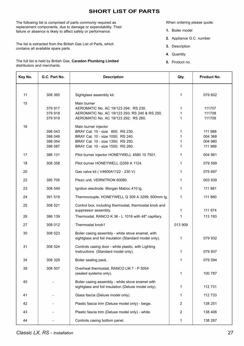
Key No. G.C. Part No. Description Qty. Product No.
11 308 365 Sightglass assembly kit. 1 079 602
15 Main burner379 917 AEROMATIC No. AC 19/123 294; RS 230. 1 111707379 918 AEROMATIC No. AC 19/123 293; RS 240 & RS 250. 1 111708379 919 AEROMATIC No. AC 19/123 292; RS 260. 1 111709
16 Main burner injector398 043 BRAY Cat. 10 - size 800; RS 230. 1 111 988398 048 BRAY Cat. 10 - size 1050; RS 240. 1 004 368398 054 BRAY Cat. 10 - size 1350; RS 250. 1 004 980398 587 BRAY Cat. 10 - size 1550; RS 260. 1 111 989
17 386 131 Pilot burner injector HONEYWELL 4580 10 7501. 1 004 981
18 308 358 Pilot burner HONEYWELL Q359 A 1124. 1 079 599
20 Gas valve kit ( V4600A1122 - 230 V) 1 075 697
22 395 705 Piezo unit, VERNITRON 60080. 1 003 939
23 308 549 Ignition electrode. Morgan Matroc 410 lg. 1 111 881
24 391 519 Thermocouple, HONEYWELL Q 309 A 3299, 600mm lg. 1 111 880
25 308 521 Control box, including thermostat, thermostat knob andsuppressor assembly. 1 111 974
26 386 139 Thermostat, RANCO K 36 - L 1016 with 48" capillary. 1 113 193
27 308 012 Thermostat knob1 013 909
30 308 523 Boiler casing assembly - white stove enamel, withsightglass and foil insulation (Standard model only). 1 079 932
31 308 524 Controls casing door - white plastic, with LightingInstructions (Standard model only). 1 079 937
34 308 329 Boiler sealing pack. 1 079 594
39 308 507 Overheat thermostat, RANCO LM 7 - P 5054(sealed systems only). 1 100 787
40 - Boiler casing assembly - white stove enamel withsightglass and foil insulation (Deluxe model only). 1 112 731
41 - Glass fascia (Deluxe model only). 1 112 733
42 - Plastic fascia trim (Deluxe model only) - beige. 2 138 251
43 - Plastic fascia trim (Deluxe model only) - white. 2 138 406
44 - Controls casing bottom panel. 1 138 267
SHORT LIST OF PARTS
When ordering please quote:
1. Boiler model
2. Appliance G.C. number
3. Description
4. Quantity
5. Product no.
The following list is comprised of parts commonly required asreplacement components, due to damage or expendability. Theirfailure or absence is likely to affect safety or performance.
The list is extracted from the British Gas List of Parts, whichcontains all available spare parts.
The full list is held by British Gas, Caradon Plumbing Limiteddistributors and merchants.

28 Classic LX, RS - Installation
SHORT LIST OF PARTS
6. Pumped return pipe7. Gravity return pipe8. Collector hood9. Combustion chamber
1. Heat exchanger2. Flue baffles4. Pumped flow pipe5. Gravity flow pipe
55 BURNER AND CONTROLS - Exploded view
15. Main burner22. Igniter button25. Control box26. Boiler thermostat27. Boiler 'stat knob
LEGEND (Numbers up to 44 relate to the B.G. spares list)
28. Thermostat pocket32. Wall mounting plate33. Back panel35. Balanced flue terminal37. Programmer (optional)39. Overheat thermostat (if fitted)100. Boiler flue duct.101. Rubber sealing grommets102. Interpanel103. Boiler drain point
54 BOILER ASSEMBLY - Exploded view
21. Gas service cock.
106. Sealing gasket
13. Burner manifold.
14. Air box & pilot burner assy.
15. Main burner.
16. Main burner injector.
19. Pilot burner shield.
20. Gas control valve.
LEGEND (Numbers up to 44 relate to B.G. spares list)

29Classic LX, RS - Installation
SHORT LIST OF PARTS57 BOILER CASING ASSEMBLY56 SHORT PARTS
Standard Model
Deluxe Model

30 Classic LX, RS - Installation
LXFF.87/AQ/220LXRS.87/AQ/221FF.87/AP/107RS.87/AP/108
Natural Gasappliances are
service listed byBritish Gas
Caradon Plumbing Limited pursues a policy of continuingimprovement in the design and performance of its products. Theright is therefore reserved to vary specification without notice.
September 1999 UIN 111 499 A06
CERTIFIED PRODUCTManufactured under a BS EN ISO 9001:1994Quality System accepted by BSI.
Caradon Plumbing Limited, P.O. Box 103, National Ave, Kingston upon Hull, HU5 4JN.Telephone: 01482 492 251 Fax: 01482 448 858. Registration No. London 322 137. RegisteredOffice: National Avenue, Kingston upon Hull, HU5 4JN. A subsidiary of Caradon p.l.c
Technical TrainingThe Caradon Plumbing Limited Technical Training Centreoffers a series of first class training courses for domestic,commercial and industrial heating installers, engineers andsystem specifiers.For details of courses please ring: .............. 01270 413624
THIS SYMBOL IS YOURASSURANCE OF QUALITY
These appliances are designed for use with NaturalGas only. They have been tested and conform withthe provisions of BS. 6332 and BS. 5258.
Ideal Installer/Technical Helpline: 01482 498663
The code of practice for the installation,commissioning & servicing of central heating systems

31Classic LX, RS - Installation
YOUR FEEDBACKand your chance to win a free boiler
At Ideal we've been leaders in the design and engineering of robust andreliable boilers for over 90 years. We want to continue as leaders bylistening to your suggestions for how to improve our boilers and our service.We will be giving away a free boiler for the five best ideas every year (tobe selected by our Technical Director). Please complete this form, usingextra sheets if required, and post it or fax it to us on 01482 498699.
Boiler details
Model / Size (e.g. Classic RS 230, Mexico CF 3/60 etc. Details on control panel door)
Date of Installation
Installer details
Name
Address
Post Code Telephone (Please include STD code)
How I would improve this boiler::
My general comments for Ideal:
Ideal Installer/Technical Helpline: 01482 498663

U.I.
N. 1
11 4
99 A
0
Caradon Plumbing Limited, PO Box 103, National Avenue, Kingston upon Hull, HU5 4JN. Telephone: 01482 492251 Fax: 01482 448858.
Further information
If you would like information about Ideal Boilers please complete thissheet and fax it to us on 01482 498699 or post it to Caradon PlumbingLimited, PO Box 103, National Avenue, Kingston upon Hull, HU5 4JN.
Installer details
Name
Address
Post Code Telephone (Please include STD code)
General information required
Please send me details of Ideal Training Courses.Please arrange for a technical representative to contact me.
Please arrange for me to join an Ideal factory tour.
Range guides required
The Ideal Guide: a specifier's and installer's introduction to theIdeal domestic boiler range.
The Ideal Householders Guide: to assist the installer whenpresenting to his/her customers.
Technical manuals required
The Ideal C class combi boiler
The Ideal Classic wall hung boiler
The Ideal Classic System wall hung boiler
The Ideal Classic LX Deluxe wall hung boiler
The Ideal Mexico floor standing boiler
The Ideal Minimiser heat-saving boiler
The Ideal Response combi. boiler
The Ideal Response SE super efficiency combi boiler
The Ideal Systemiser SE super efficiency system boiler
The Ideal Concord high output boiler
The Ideal Buccaneer oil fired boiler
Ideal Installer/Technical Helpline: 01482 498663
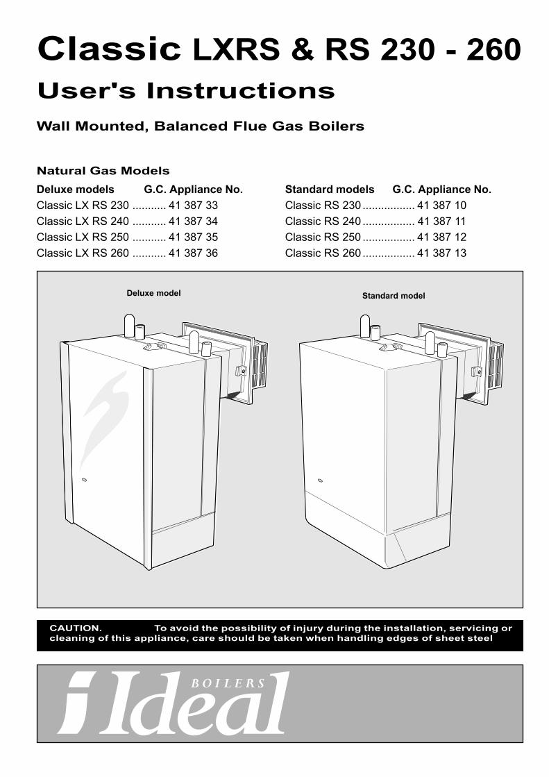
Deluxe model Standard model
Standard models G.C. Appliance No.Classic RS 230 ................. 41 387 10Classic RS 240 ................. 41 387 11Classic RS 250 ................. 41 387 12Classic RS 260 ................. 41 387 13
Classic LXRS & RS 230 - 260User's InstructionsWall Mounted, Balanced Flue Gas Boilers
Natural Gas ModelsDeluxe models G.C. Appliance No.Classic LX RS 230 ........... 41 387 33Classic LX RS 240 ........... 41 387 34Classic LX RS 250 ........... 41 387 35Classic LX RS 260 ........... 41 387 36
CAUTION. To avoid the possibility of injury during the installation, servicing orcleaning of this appliance, care should be taken when handling edges of sheet steel

2 Classic LXRS & RS - User's
GAS SAFETY (INSTALLATION AND USE) Regulations,1994, amendments 1996 or rules in force.It is law that all gas appliances are installed by a CORGI registeredinstaller ( identified by ) in accordance with the aboveregulations. Failure to install appliances correctly could lead toprosecution. It is in your own interest, and that of safety, to ensurethe law is complied with.
It is essential that the instructions in this bookletare strictly followed for safe and economicaloperation of the boiler.
ELECTRICITY SUPPLYThis appliance must be efficiently earthed.
This appliance requires 230 V ~ 50Hz.
This appliance must be connected to the supply via a double poleswitch, fused at 3 A, having a 3mm (1/8") contact separation inboth poles, serving only the boiler and system controls.
TO LIGHT THE BOILER. Refer to Frame 1
1. CHECK THAT THE ELECTRICITY SUPPLY TO THE BOILER IS OFF.
2. Deluxe Model (LX)Lift the glass fascia and support with sliding catch.Standard model.Open the controls access door by hinging downwards.
3. Ensure that the gas inlet cock (E) is OPEN.
4. Ensure that the boiler thermostat knob (C) is in the OFF (0)position.
5. Turn the gas control knob (A) to the RIGHT until resistance isfelt, then release it. WAIT FOR 3 MINUTES
6. Push in the gas control knob (A) and hold it depressed. Pushin and release the igniter button (D) repeatedly until the pilotflame can be seen through the sightglass (B). When the pilothas lit, continue to press in the gas control knob for a further15 seconds.
7. Should the pilot go out at this or any other stage turn thegas control knob (A) to the RIGHT.
WAIT FOR 3 MINUTES then repeat instruction 6 but waitfor longer than 15 seconds before releasing the gas controlknob (A).
8. Switch ON the electricity supply to the boiler. Check that allexternal controls, e.g. room thermostat etc., are ON.
9. Turn the boiler thermostat knob (C) to position 6 and the boilerwill l ight.Set the boiler thermostat to the desired position.
10. Deluxe Model (LX)Lower the glass fascia after pushing in the sliding catch.Standard model.Close the controls access door.
In winter conditions, i.e. central heating and domestic hot water,the thermostat should be set at position 5 or 6.
For summer conditions, i.e. domestic hot water only, thethermostat should be set at position 3.
These settings, however, are offered for general guidance onlyand other settings may be found preferable, dependent upon thetype of system installed or as recommended by the installer.
Approx. flow temperatures for the boiler thermostat settings are:
Knob Setting Flow Temperature°C °F
1 56 133
2 61 142
3 66 152
4 72 161
5 77 170
6 82 180
MINIMUM CLEARANCESThe minimum clearances given below MUST be complied within order to maintain the safe running of the boiler and tofacilitate servicing.
Above the boiler 100 mm (4")
At each side of the boiler 5 mm (1/4")
Underneath the boiler 100 mm (4")
In front of the boiler 450 mm (17 3 /4")
IMPORTANT NOTES
a. This appliance must not be operated without the casingcorrectly fitted and forming an adequate seal.
b. If the boiler is installed in a compartment then the compartmentMUST NOT be used for storage purposes.
c. The ventilation provided for the boiler during installation MUSTNOT be blocked and a check should be made periodicallythat the ventilation areas are free from any obstruction.
d. If it is known or suspected that a fault exists on the boiler thenit MUST NOT be used until the fault has been corrected by aCORGI registered installer.
THE LOG BOOK SHOULD BE COMPLETED AFTEREACH SERVICE AND KEPT WITH THESE
INSTRUCTIONS

3Classic LXRS & RS - User's
1 BOILER CONTROLS
TO SHUT DOWN THE BOILER1. For short periods
Turn the boiler thermostat knob to OFF. When heating isagain required, restore the knob to its original settings.
2. For longer periodsTurn the boiler thermostat knob to OFF. Turn the gascontrol knob (A) to the right until resistance is felt thenrelease it to extinguish the pilot burner.
Switch the electricity supply to OFF.
WARNING. If no frost protection is provided and frost is likelyduring a short absence from home, leave the heating controls ata reduced temperature setting.
For longer periods, the entire system should be drained - includingthe domestic water supply. If the system includes a frostthermostat then, during cold weather, the boiler should be turnedOFF at the time switch(es) ONLY. The mains supply should beleft switched ON, with the boiler thermostat left in the normalrunning position.
View inside controls area
LEGEND
A. Gas control knob
B. Sightglass
C. Thermostat knob
D. Igniter button
E. Gas inlet cock (shown in the OPENposition)
F. Overheat thermostat reset button (iffitted)
Standard Model Deluxe Model
BOILER OVERHEAT THERMOSTAT (If fitted)The boiler is fitted with a safety 'cutout' thermostat. This thermostatwill extinguish the pilot and shut down the boiler in the event ofoverheating.
Should this occur allow the boiler to cool, press the reset button(F) then relight as detailed in steps 1-10 in 'To light the boiler'.
If the cutout condition still persists then turn off the boiler andconsult a CORGI registered installer.
CONTROL OF WATER TEMPERATURE1. Adjust the boiler thermostat (C) to give the required
temperature for central heating.
2. The boiler thermostat automatically switches the mainburner OFF and ON to maintain the selected temperature.The pilot burner remains alight continuously to give re-ignition of the main burner.

TO RELIGHT THE BOILERRepeat the procedure from 1-10, detailed in 'To light the boiler'.
LOSS OF SYSTEM WATER PRESSUREStandard boilers fitted with Classic Sealed System Units only
If the red arrow on the module pressure gauge is set abovezero and the system pressure is seen to fall below this valueover a period of time then a water leak is indicated. In thisevent a CORGI registered installer should be consulted.
DO NOT OPERATE THE BOILER IF THE PRESSURE HASREDUCED TO ZERO FROM THE ORIGINAL SETTING.
Ideal Consumer Helpline Tel: 01482 498 660
September 1999 UIN 111 500 A04
Caradon Plumbing Limited, P.O. Box 103, National Ave, Kingston upon Hull, HU5 4JN.Telephone: 01482 492 251 Fax: 01482 448 858. Registration No. London 322 137. RegisteredOffice: National Avenue, Kingston upon Hull, HU5 4JN. A subsidiary of Caradon plc
The code of practice for the installation,commissioning & servicing of central heating systems
Caradon Plumbing Limited is a member of theBenchmark initiative and fully supports the aims of the
programme. Benchmark has been introduced toimprove the standards of installation and
commissioning of central heating systems in the UKand to encourage the regular servicing of all central
heating systems to ensure safety and efficiency.
ESCAPE OF GASShould a gas leak be suspected, contact your gas supplierwithout delay.
Do NOT search for gas leaks with a naked flame.
CLEANINGFor normal cleaning simply dust with a dry cloth.To remove stubborn marks and stains, wipe with a damp clothand finish off with a dry cloth.
Do NOT use abrasive cleaning materials.
MAINTENANCEThe appliance should be serviced at least once a year by aCORGI registered installer.
THIS SYMBOL IS YOURASSURANCE OF QUALITY
CERTIFIED PRODUCTManufactured under a BS EN ISO 9001:1994Quality System accepted by BSI
These appliances are designed for use withNatural Gas only. They have been tested andconform with the provisions of BS. 6332 and BS.5258.
Caradon Plumbing Limited pursues a policy of continuingimprovement in the design and performance of its products. Theright is therefore reserved to vary specification without notice.
Natural Gasappliances areservice listed byBritish Gas
LXFF.87/AQ/220LXRS.87/AQ/221FF. 87/AP/107RS.87/AP/108