Embed Size (px)
Citation preview

RS-422/485 Application Note 1 1992 B&B Electronics •• PO Box 1040 •• Ottawa, IL 61350
RS-422 and RS-485 Application NoteINTRODUCTION
The purpose of this application note is to attempt to describe themain elements of an RS-422 and RS-485 system. This applicationnote attempts to cover enough technical details so that the systemdesigner will have considered all important aspects in his data systemdesign. Since both RS-422 and RS-485 are data transmission systemsthat use balanced differential signals, it is appropriate to discuss bothsystems in the same application note.
DATA TRANSMISSION WITH BALANCEDDIFFERENTIAL SIGNALSBalanced Line Drivers
Each signal that transmits in an RS-232 unbalanced datatransmission system appears on the interface connector as a voltage withreference to a signal ground. For example, the transmitted data (TD)from a DTE device appears on pin 2 with respect to pin 7 (signal ground).This voltage will be negative if the line is idle and alternate between thatnegative level and a positive level when data is sent. The RS-232receiver operates within the voltage range shown in Figure 1. Themagnitude will vary from 3 to 12 volts (see Figure 1). The RS-232 driverproduces an output voltage within the range of + or -5 to 15 volts.
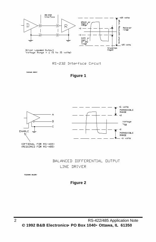
In a balanced differential system the voltage produced by the driverappears across a pair of signal lines that transmit only one signal.Figure 2 shows a schematic symbol for a balanced line driver and thevoltages that exist. A balanced line driver will produce a voltage from 2to 6 volts across its A and B output terminals. A balanced line driverwill have signal ground (C) connection. Although proper connection tothe signal ground is important, it isn't used by a balanced line receiverin determining the logic state of the data line. A balanced line drivercan also have an input signal called an "Enable" signal. The purposeof this signal is to connect the driver to its output terminals, A and B. Ifthe "Enable" signal is OFF, one can consider the driver asdisconnected from the transmission line. An RS-485 driver must havethe "Enable" control signal. An RS-422 driver may have this signal, butit is not always required. The disconnected or "disabled" condition ofthe line driver usually is referred to as the "tristate" condition of thedriver.
2 RS-422/485 Application Note 1992 B&B Electronics •• PO Box 1040 •• Ottawa, IL 61350
Figure 1
Figure 2
RS-422/485 Application Note 3 1992 B&B Electronics •• PO Box 1040 •• Ottawa, IL 61350
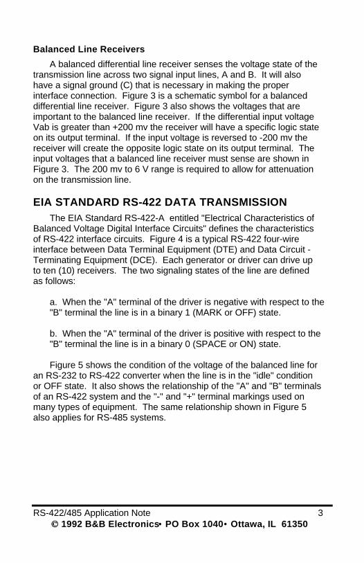
Balanced Line Receivers
A balanced differential line receiver senses the voltage state of thetransmission line across two signal input lines, A and B. It will alsohave a signal ground (C) that is necessary in making the properinterface connection. Figure 3 is a schematic symbol for a balanceddifferential line receiver. Figure 3 also shows the voltages that areimportant to the balanced line receiver. If the differential input voltageVab is greater than +200 mv the receiver will have a specific logic stateon its output terminal. If the input voltage is reversed to -200 mv thereceiver will create the opposite logic state on its output terminal. Theinput voltages that a balanced line receiver must sense are shown inFigure 3. The 200 mv to 6 V range is required to allow for attenuationon the transmission line.
EIA STANDARD RS-422 DATA TRANSMISSIONThe EIA Standard RS-422-A entitled "Electrical Characteristics of
Balanced Voltage Digital Interface Circuits" defines the characteristicsof RS-422 interface circuits. Figure 4 is a typical RS-422 four-wireinterface between Data Terminal Equipment (DTE) and Data Circuit -Terminating Equipment (DCE). Each generator or driver can drive upto ten (10) receivers. The two signaling states of the line are definedas follows:
a. When the "A" terminal of the driver is negative with respect to the"B" terminal the line is in a binary 1 (MARK or OFF) state.
b. When the "A" terminal of the driver is positive with respect to the"B" terminal the line is in a binary 0 (SPACE or ON) state.
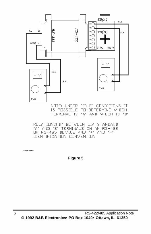
Figure 5 shows the condition of the voltage of the balanced line foran RS-232 to RS-422 converter when the line is in the "idle" conditionor OFF state. It also shows the relationship of the "A" and "B" terminalsof an RS-422 system and the "-" and "+" terminal markings used onmany types of equipment. The same relationship shown in Figure 5also applies for RS-485 systems.

4 RS-422/485 Application Note 1992 B&B Electronics •• PO Box 1040 •• Ottawa, IL 61350
Figure 3

RS-422/485 Application Note 5 1992 B&B Electronics •• PO Box 1040 •• Ottawa, IL 61350
Figure 4
6 RS-422/485 Application Note 1992 B&B Electronics •• PO Box 1040 •• Ottawa, IL 61350
Figure 5
RS-422/485 Application Note 7 1992 B&B Electronics •• PO Box 1040 •• Ottawa, IL 61350
For high data rates it is recommen ded that the transmission line beterminated. A typical termination resistor of 100 ohms 1/2 watt isshown in Figure 4. The transmission line's characteristic impedanceshould be used in selecting this resistor. A terminating resistor of lessthan 90 ohms should not be used. If the line is driven by an RS-422driver that is never "tristated" or disconnected from the line, there is noneed to terminate the line at the driver. The driver provides a lowinternal impedance that terminates the line at that end. Note that thesignal ground line is also connected in the system shown in Figure 4.This connection is necessary to keep the Vcm common mode voltageat the receiver within the -7 V to + 7 V range. This interface circuit mayoperate without the signal ground connection, but may not be reliable.
Other aspects of RS-422 such as cable selection and data rateswill be discussed in the RS-485 section of this application note. Thetechnical aspects of these topics are the same for RS-422 and RS-485.
EIA STANDARD RS-485DATA TRANSMISSION
The RS-485 Standard permits a balanced transmission line to beshared in a party line mode. As many as 32 driver/receiver pairs canshare a two-wire party line network. Many characteristics of the driversand receivers are the same as RS-422. The range of the commonmode voltage Vcm that the driver and receiver can tolerate is expandedto +12 to -7 volts. Since the driver can be disconnected or tristatedfrom the line, it must withstand this common mode voltage range whilein the tristate condition. Some RS-422 drivers, even with tristatecapability, will not withstand the full voltage range of +12 to -7 volts.
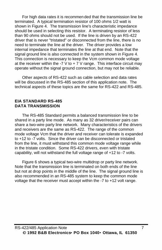
Figure 6 shows a typical two-wire multidrop or party line network.Note that the transmission line is terminated on both ends of the linebut not at drop points in the middle of the line. The signal ground line isalso recommended in an RS-485 system to keep the common modevoltage that the receiver must accept within the -7 to +12 volt range.
8 RS-422/485 Application Note 1992 B&B Electronics •• PO Box 1040 •• Ottawa, IL 61350
Figure 6
RS-422/485 Application Note 9 1992 B&B Electronics •• PO Box 1040 •• Ottawa, IL 61350
Figure 7
10 RS-422/485 Application Note 1992 B&B Electronics •• PO Box 1040 •• Ottawa, IL 61350
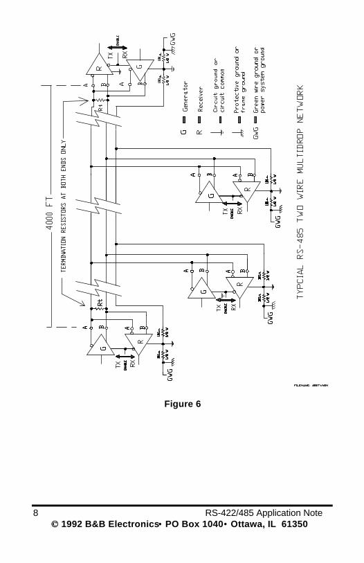
An RS-485 network can also be connected in a four-wire mode(see Figure 7). In a four-wire network it is necessary that one node bea master node and all other be slaves. The network is connected sothat the master node communicates to all slave nodes. All slave nodescommunicate only with the master node. This network has someadvantages with equipment with mixed protocol communications.Since the slave nodes never listen to another slave response to themaster, a slave node cannot reply incorrectly to another slave node.
RTS Control of an RS-485 Converter
As discussed previously, an RS-485 system must have a driverthat can be disconnected from the transmission line when a particularnode is not transmitting. In an RS-232 to RS-485 converter, this ismost often implemented by using the RTS control signal from anasynchronous serial port to enable the RS-485 driver. Figure 8 showsa timing diagram for a typical RS-232 to RS-485 converter. Thewaveforms show what happens if the VRTS waveform is narrower thanthe data VSD. This is not the normal situation, but is shown here toillustrate the loss of a portion of the data waveform. When RTS controlis used, it is important to be certain that the "RTS" active signalhappens before data is sent. Also, the "RTS" inactive signal musthappen after the last data bit is sent. This timing is done by thesoftware used to control the serial port and not by the converter.
When an RS-485 network is connected in a two-wire multidropparty line mode, the receiver at each node will be connected to the line(see Figure 6). If B & B Electronics converters are used in the system,it is possible to connect the receivers so they receive when the driver(at the same node) is transmitting. Some of B & B Electronicsconverters can be configured to receive all of the time. Be sure tocheck the data sheet for your converter to determined how the receiver"enable" function is connected.
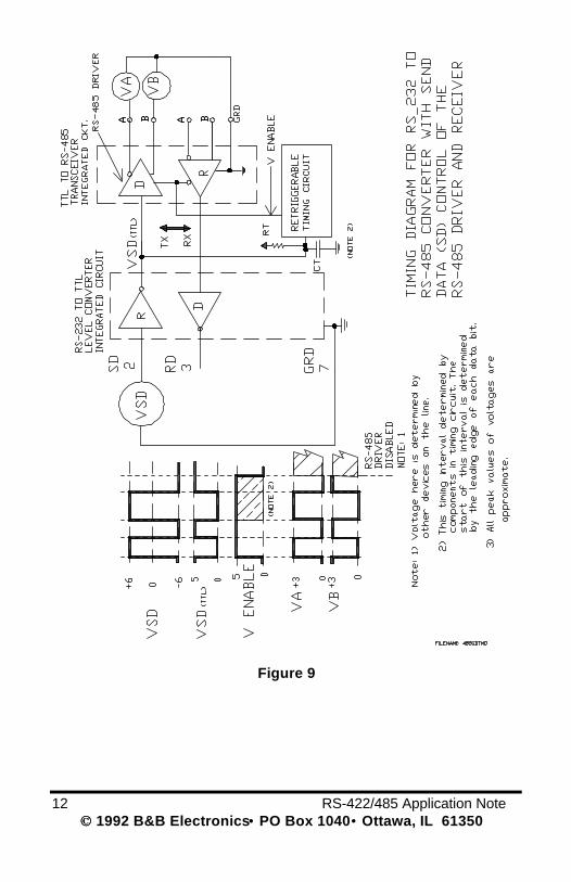
SD Send Data Control of an RS-485 Converter
An RS-232 to RS-485 converter can also be controlled by triggeringfrom the data signal to enable the RS-485 driver.Figure 9 is a timing diagram of the important signals used to

RS-422/485 Application Note 11 1992 B&B Electronics •• PO Box 1040 •• Ottawa, IL 61350
Figure 8
12 RS-422/485 Application Note 1992 B&B Electronics •• PO Box 1040 •• Ottawa, IL 61350
Figure 9
RS-422/485 Application Note 13 1992 B&B Electronics •• PO Box 1040 •• Ottawa, IL 61350
control a converter of this type. It is important to note that thetransmitted data line is "disabled" after a fixed interval, after the leadingedge of the last bit. If this interval is too short, you can miss parts ofeach character being sent. If this time is too long, your system may tryto turn the data line around from transmit to receive before the node(with the SD converter) is ready to receive data. If the latter is thecase, you will miss portions (or complete characters) at the beginningof a message.
Transmission Line Termination
A common method of terminating a two-wire party line RS-485network is with terminating resistors installed at the ends of themultidrop network (see Figure 6). The termination resistor shouldmatch the characteristic impedance of the transmission line. Thischaracteristic impedance will usually be in the range of 100 to 120ohms. Check the manufacturer's data sheets on the cable you areusing in your system.
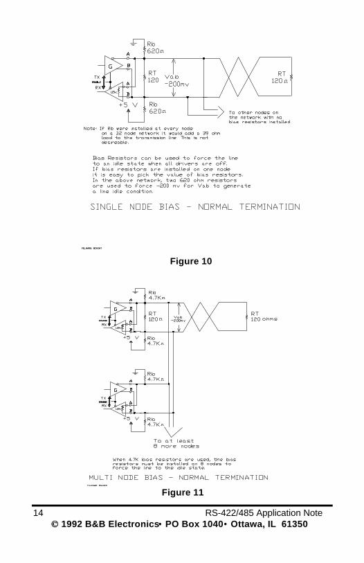
Idle or Off State Biasing on an RS-485 NetworkWhen all nodes finish transmitting, the network is at an idle
condition with all nodes in listen or receive mode. Under this idlecondition, the state of the balanced line can be indeterminate becauseall drivers are tristated. If the voltage level at the A and B inputs is lessthan +/- 200 mv the logic level at the output of the receivers will be thevalue of the last bit received. It is often necessary to force to state ofthe line to be in an idle condition where Vab is less than -200 mv. Thiscan be done with bias resistors as shown in Figure 10. If the networkbias consists of two resistors installed at one node, it would take two620 ohm resistors to force a -200 mv condition to Vab. This calculationuses the assumption that only two 120 ohm terminating resistors areused, with 32 nodes each with a nominal input impedance of 12 kohms. It is important to note that the two 620 ohm bias resistors canonly be installed on one node in the network. If these two resistors areinstalled at every node, it would effectively add a 39 ohm load acrossthe network.
Multinode Bias ResistorsMany of B & B Electronics' converters use 4.7K ohm bias resistors as
shown in Figure 11. When these resistors are installed only at one node,the line will not be forced to the idle state. It will take at least 8 nodes toget this condition, in a 32-node network.
14 RS-422/485 Application Note 1992 B&B Electronics •• PO Box 1040 •• Ottawa, IL 61350
Figure 10
Figure 11
RS-422/485 Application Note 15 1992 B&B Electronics •• PO Box 1040 •• Ottawa, IL 61350
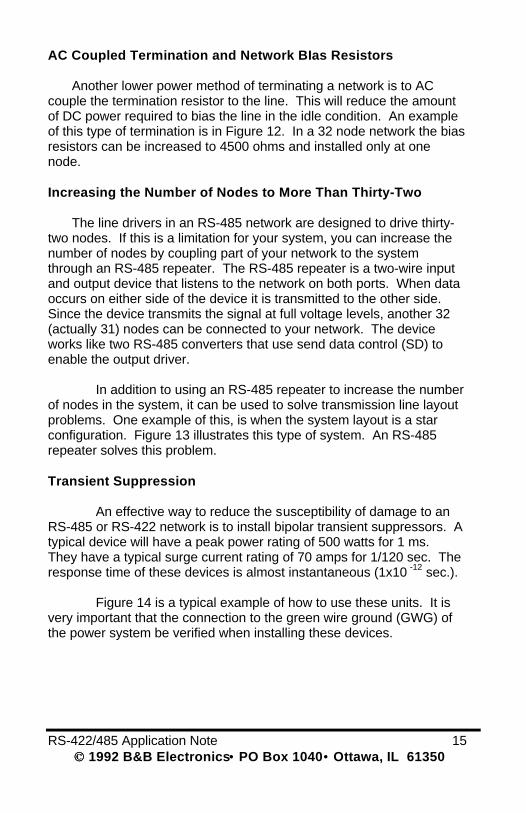
AC Coupled Termination and Network BIas Resistors
Another lower power method of terminating a network is to ACcouple the termination resistor to the line. This will reduce the amountof DC power required to bias the line in the idle condition. An exampleof this type of termination is in Figure 12. In a 32 node network the biasresistors can be increased to 4500 ohms and installed only at onenode.
Increasing the Number of Nodes to More Than Thirty-Two
The line drivers in an RS-485 network are designed to drive thirty-two nodes. If this is a limitation for your system, you can increase thenumber of nodes by coupling part of your network to the systemthrough an RS-485 repeater. The RS-485 repeater is a two-wire inputand output device that listens to the network on both ports. When dataoccurs on either side of the device it is transmitted to the other side.Since the device transmits the signal at full voltage levels, another 32(actually 31) nodes can be connected to your network. The deviceworks like two RS-485 converters that use send data control (SD) toenable the output driver.
In addition to using an RS-485 repeater to increase the numberof nodes in the system, it can be used to solve transmission line layoutproblems. One example of this, is when the system layout is a starconfiguration. Figure 13 illustrates this type of system. An RS-485repeater solves this problem.
Transient Suppression
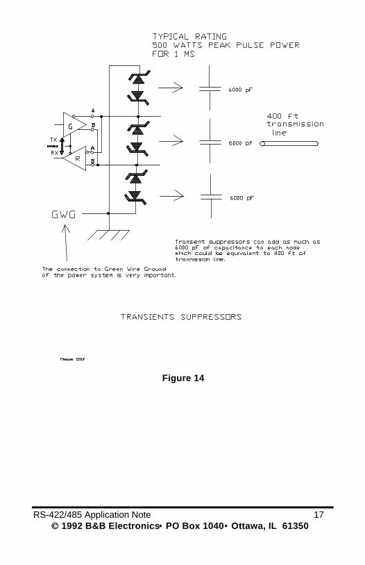
An effective way to reduce the susceptibility of damage to anRS-485 or RS-422 network is to install bipolar transient suppressors. Atypical device will have a peak power rating of 500 watts for 1 ms.They have a typical surge current rating of 70 amps for 1/120 sec. Theresponse time of these devices is almost instantaneous (1x10 -12 sec.).
Figure 14 is a typical example of how to use these units. It isvery important that the connection to the green wire ground (GWG) ofthe power system be verified when installing these devices.

16 RS-422/485 Application Note 1992 B&B Electronics •• PO Box 1040 •• Ottawa, IL 61350
Figure 12
Figure 13
RS-422/485 Application Note 17 1992 B&B Electronics •• PO Box 1040 •• Ottawa, IL 61350
Figure 14
18 RS-422/485 Application Note 1992 B&B Electronics •• PO Box 1040 •• Ottawa, IL 61350
A disadvantage of installing transient suppressors on all nodes in anetwork is the capacitive loading that these devices add to thetransmission line. These devices can have capacitances of 6000 pF.that can be equivalent to as much as 400 ft. of transmission line. If youuse these devices, you may not be able to use a 4000 ft. line.
SELECTION OF TRANSMISSION LINE FOR RS-422 AND RS-485
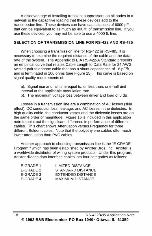
When choosing a transmission line for RS-422 or RS-485, it isnecessary to examine the required distance of the cable and the datarate of the system. The Appendix to EIA RS-422-A Standard presentsan empirical curve that relates Cable Length to Data Rate for 24 AWGtwisted-pair telephone cable that has a shunt capacitance of 16 pF/ft.and is terminated in 100 ohms (see Figure 15). This curve is based onsignal quality requirements of:
a). Signal rise and fall time equal to, or less than, one-half unitinterval at the applicable modulation rate.b). The maximum voltage loss between driver and load of 6 dB.
Losses in a transmission line are a combination of AC losses (skineffect), DC conductor loss, leakage, and AC losses in the dielectric. Inhigh quality cable, the conductor losses and the dielectric losses are onthe same order of magnitude. Figure 16 is included in this applicationnote to point out the significant difference in performance of differentcables. This chart shows Attenuation versus Frequency for threedifferent Belden cables. Note that the polyethylene cables offer muchlower attenuation than PVC cables.
Another approach to choosing transmission line is the "E-GRADEProgram," which has been established by Anixter Bros. Inc. Anixter isa worldwide distributor of wiring system products. Under this program,Anixter divides data interface cables into four categories as follows:
E-GRADE 1 LIMITED DISTANCEE-GRADE 2 STANDARD DISTANCEE-GRADE 3 EXTENDED DISTANCEE-GRADE 4 MAXIMUM DISTANCE
RS-422/485 Application Note 19 1992 B&B Electronics •• PO Box 1040 •• Ottawa, IL 61350
Figure 15
Figure 16
20 RS-422/485 Application Note 1992 B&B Electronics •• PO Box 1040 •• Ottawa, IL 61350
Simple charts are used to help the user select the proper cablewithout any technical understanding of the cable parameters. Thisprogram divides the usage categories into EIA-232-D, EIA-422-A, andEIA-423-A. When using this literature, use the EIA-422-A charts forchoosing RS-485 cable.
EIA STANDARD RS-423 DATA TRANSMISSION
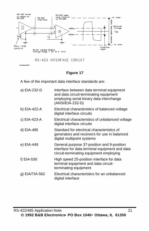
RS-423 data transmission uses an unbalanced line driver thatconnects to a RS-422 type balanced line receiver as shown in Figure17. The RS-423 line driver is unique to this system. It producesvoltage similar to RS-232 but has a slew rate control input that is usedto limit rise times and cross talk on the data lines. Typical adjustmentson the slew rate control is from 1 to 100 us. This is done by the properselection of one resistor on the wave shape control input.
OBTAINING EIA DATA INTERFACE STANDARDS
EIA Standards and Publications can be purchased from:
GLOBAL ENGINEERING DOCUMENTS2805 McGaw AvenueIrvine, CA 92714Phone: (714) 261-1455FAX: (714) 261-7892
GLOBAL ENGINEERING DOCUMENTS7730 Carondelet AvenueClayton, MO 63105Phone: (314) 726-0444FAX: (314) 726-6418
GLOBAL ENGINEERING DOCUMENTS1990 M Street N.W.Washington, DC 20036Phone: (202) 429-2860FAX: (202) 331-0960
RS-422/485 Application Note 21 1992 B&B Electronics •• PO Box 1040 •• Ottawa, IL 61350
Figure 17
A few of the important data interface standards are:
a) EIA-232-D Interface between data terminal equipmentand data circuit-terminating equipmentemploying serial binary data interchange(ANSI/EIA-232-D)
b) EIA-422-A Electrical characteristics of balanced voltagedigital interface circuits
c) EIA-423-A Electrical characteristics of unbalanced voltagedigital interface circuits
d) EIA-485 Standard for electrical characteristics ofgenerators and receivers for use in balanceddigital multipoint systems
e) EIA-449 General purpose 37-position and 9-positioninterface for data terminal equipment and datacircuit-terminating equipment employing
f) EIA-530 High speed 25-position interface for dataterminal equipment and data circuit-terminating equipment
g) EIA/TIA-562 Electrical characteristics for an unbalanceddigital interface
22 RS-422/485 Application Note 1992 B&B Electronics •• PO Box 1040 •• Ottawa, IL 61350
RS-422/485 Application Note 23 1992 B&B Electronics •• PO Box 1040 •• Ottawa, IL 61350