Embed Size (px)
Citation preview

RS-125/230 User Manual
Revision 1.05 – December 2015
Firmware Version 5v95
Part Number D-1009
D-1009 REV 01.05 Status: RELEASED printed 18/12/2015 5:26:09 PM by Radiation Solutions Inc.

D-1009 REV 01.05 Status: RELEASED printed 18/12/2015 5:26:09 PM by Radiation Solutions Inc.

RS-125/230 User Manual – Revision 1.05
Radiation Solutions Inc – Proprietary Page iii Revision Date: December 11, 2015
Revision History
Date Revision ECO # Description
May 20, 2014 01.00 NA New PN and Rev in accordance with PN restructuring and QCBD software issues
Aug 18, 2014 01.01 15 Update Revision History
Oct 21, 2014 01.02 38 Correct Title Page (RS-125/230)
April 28,2015 01.03 62 Update to Firmware Version 5v95
Nov 06, 2015 01.04 85 Change company address
Dec 11, 2015 01.05 90 Update with new screenshots
Product Manual - Disclaimers:
Due to our efforts to continuously improve this product; specifications, dimensions, operating features and procedures described in this manual are subject to frequent changes. The printed version of this manual reflects only the configuration current at the time of printing. The most current version of the manual is provided in electronic format on the Product Support CD supplied with the instrument. Please refer to the electronic version of the manual for the most accurate interpretation.
PRODUCT STATEMENT The RS-125 and RS-230 are a joint venture between RADIATION SOLUTIONS INC a Mississauga (Toronto) based geophysical equipment manufacturer and GEORADIS a Czech Republic based design company who were previously part of Exploranium but are now an independent private company.
ADVISORY
NOTE: Users are advised that the manual and software supplied with the instrument are current when manufactured, however, a program of continuous improvement means that many new features are added and old ones improved with time. Users are advised to contact RSI directly for new releases including new manuals and software.
NOTE: USERS ARE REMINDED THAT THE RS-125/230, IN COMMON WITH OTHER SIMILAR INSTRUMENTS, USES A Sodium-Iodide CRYSTAL AS THE DETECTOR. THIS CRYSTAL IS FRAGILE AND EVEN THOUGH THE UNIT HAS BEEN RUGGEDISED FOR FIELD USE GREAT CARE SHOULD BE TAKEN TO AVOID ABUSING THE INSTRUMENT AS THE VERY EXPENSIVE CRYSTAL IS NOT COVERED UNDER WARRANTY.
D-1009 REV 01.05 Status: RELEASED printed 18/12/2015 5:26:09 PM by Radiation Solutions Inc.

RS-125/230 User Manual – Revision 1.05
Radiation Solutions Inc – Proprietary Page iv Revision Date: December 11, 2015
CONFIDENTIAL DISCLOSURE
USERS ARE HEREBY NOTIFIED THAT THIS MANUAL CONTAINS TECHNICAL INFORMATION OF A PROPRIETARY NATURE. THIS INFORMATION IS NECESSARY FOR TECHNICALLY KNOWLEDGEABLE USERS TO UNDERSTAND SYSTEM OPERATION AND TO SATISFY THEMSELVES THAT THE SYSTEM IS PERFORMING CORRECTLY. RADIATION SOLUTIONS INC ACCEPTS THAT IT IS THE RIGHT OF SUCH USERS TO BE PRIVY TO THIS INFORMATION. HOWEVER THIS DOCUMENTATION IS PROVIDED SOLELY FOR THE BENEFIT OF OWNERS OF THE SUPER-SPEC HANDHELD DETECTOR SYSTEM AND DISSEMINATION OF THE DETAILED TECHNICAL INFORMATION PROVIDED MAY BE CONSIDERED AS LEGALLY CONTRAVENING THE NORMAL SUPPLIER/CUSTOMER RELATIONSHIP. UNAUTHORIZED RELEASE OF DETAILED TECHNICAL INFORMATION TO A THIRD PARTY WILL BE CONSIDERED AS A CONTRAVENTION OF USER AGREEMENTS.
Manufactured by Radiation Solutions Inc, 5875 Whittle Road, Mississauga, Ontario, Canada, L4Z 2H4
D-1009 REV 01.05 Status: RELEASED printed 18/12/2015 5:26:09 PM by Radiation Solutions Inc.
RS-125/230 User Manual – Revision 1.05
Radiation Solutions Inc – Proprietary Page v Revision Date: December 11, 2015
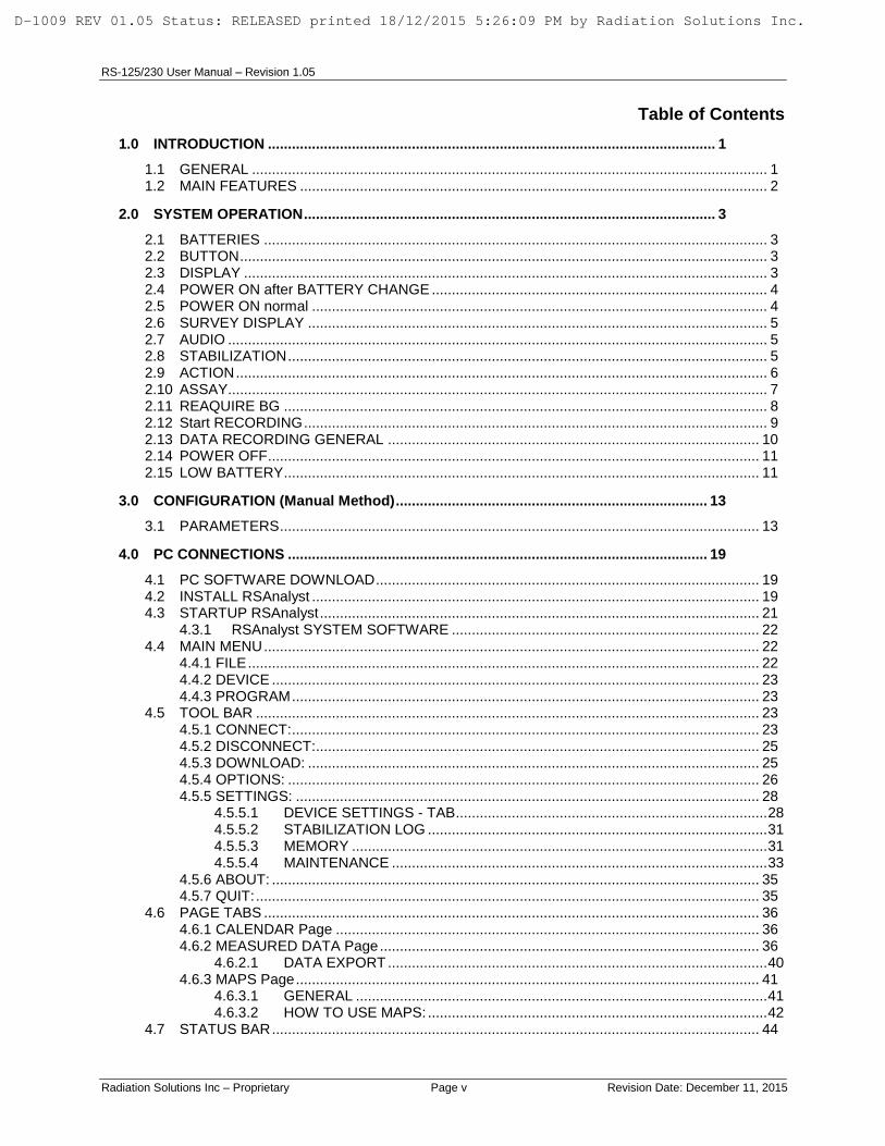
Table of Contents
1.0 INTRODUCTION ................................................................................................................ 1
1.1 GENERAL ................................................................................................................................. 1 1.2 MAIN FEATURES ..................................................................................................................... 2
2.0 SYSTEM OPERATION ....................................................................................................... 3
2.1 BATTERIES .............................................................................................................................. 3 2.2 BUTTON .................................................................................................................................... 3 2.3 DISPLAY ................................................................................................................................... 3 2.4 POWER ON after BATTERY CHANGE .................................................................................... 4 2.5 POWER ON normal .................................................................................................................. 4 2.6 SURVEY DISPLAY ................................................................................................................... 5 2.7 AUDIO ....................................................................................................................................... 5 2.8 STABILIZATION ........................................................................................................................ 5 2.9 ACTION ..................................................................................................................................... 6 2.10 ASSAY....................................................................................................................................... 7 2.11 REAQUIRE BG ......................................................................................................................... 8 2.12 Start RECORDING .................................................................................................................... 9 2.13 DATA RECORDING GENERAL ............................................................................................. 10 2.14 POWER OFF ........................................................................................................................... 11 2.15 LOW BATTERY ....................................................................................................................... 11
3.0 CONFIGURATION (Manual Method) .............................................................................. 13
3.1 PARAMETERS ........................................................................................................................ 13
4.0 PC CONNECTIONS ......................................................................................................... 19
4.1 PC SOFTWARE DOWNLOAD ................................................................................................ 19 4.2 INSTALL RSAnalyst ................................................................................................................ 19 4.3 STARTUP RSAnalyst .............................................................................................................. 21
4.3.1 RSAnalyst SYSTEM SOFTWARE ............................................................................. 22 4.4 MAIN MENU ............................................................................................................................ 22
4.4.1 FILE ................................................................................................................................ 22 4.4.2 DEVICE .......................................................................................................................... 23 4.4.3 PROGRAM ..................................................................................................................... 23
4.5 TOOL BAR .............................................................................................................................. 23 4.5.1 CONNECT: ..................................................................................................................... 23 4.5.2 DISCONNECT: ............................................................................................................... 25 4.5.3 DOWNLOAD: ................................................................................................................. 25 4.5.4 OPTIONS: ...................................................................................................................... 26 4.5.5 SETTINGS: .................................................................................................................... 28
4.5.5.1 DEVICE SETTINGS - TAB .............................................................................. 28 4.5.5.2 STABILIZATION LOG ..................................................................................... 31 4.5.5.3 MEMORY ........................................................................................................ 31 4.5.5.4 MAINTENANCE .............................................................................................. 33
4.5.6 ABOUT: .......................................................................................................................... 35 4.5.7 QUIT: .............................................................................................................................. 35
4.6 PAGE TABS ............................................................................................................................ 36 4.6.1 CALENDAR Page .......................................................................................................... 36 4.6.2 MEASURED DATA Page ............................................................................................... 36
4.6.2.1 DATA EXPORT ............................................................................................... 40 4.6.3 MAPS Page .................................................................................................................... 41
4.6.3.1 GENERAL ....................................................................................................... 41 4.6.3.2 HOW TO USE MAPS: ..................................................................................... 42
4.7 STATUS BAR .......................................................................................................................... 44
D-1009 REV 01.05 Status: RELEASED printed 18/12/2015 5:26:09 PM by Radiation Solutions Inc.

RS-125/230 User Manual – Revision 1.05
Radiation Solutions Inc – Proprietary Page vi Revision Date: December 11, 2015
5.0 Rechargeable Battery SET ............................................................................................. 45
Appendix A - ASSAY ANALYSIS ............................................................................................ 47
Appendix B - Fast GPS Sampling on Total Count Data ....................................................... 51
Appendix C – RS-230 System Stabilization and Data Reliability ........................................ 53
C.1 GENERAL ................................................................................................................................ 53 C.2 STABILIZATION ....................................................................................................................... 53 C.3 DATA RELIABILITY .................................................................................................................. 53
Appendix D Calibration of the RS-125 and/or RS-230 ....................................................... 57
D.1 GENERAL: ............................................................................................................................... 57 D.2 REQUIRED ITEMS .................................................................................................................. 57 D.3 LOAD CALIBRATION FILE ...................................................................................................... 57 D.4 ENABLE CALIBRATION MODE .............................................................................................. 58 D.5 CALIBRATE UNIT .................................................................................................................... 59
Appendix Z WARRANTY ....................................................................................................... 61
System Requirements:
Hardware:
Protective boot with carry straps.
Software:
GEORADiS RSAnalyst (check with RSI for latest software and firmware upgrade)
NOTE: The latest software, firmware and documentation version are available from RSI (see Appendix Z). Updating the software alone may update undocumented features so the rule is if you want to update – then update BOTH the RSAnalyst and the units’ internal FIRMWARE.
D-1009 REV 01.05 Status: RELEASED printed 18/12/2015 5:26:09 PM by Radiation Solutions Inc.

RS-125/230 User Manual – Revision 1.05 INTRODUCTION
Radiation Solutions Inc – Proprietary Page 1 Revision Date: December 11, 2015
1.0 INTRODUCTION
1.1 GENERAL
The new RS-125/230 Spectrometer is the state-of-the art in portable hand-held radiation spectrometer survey instrument for the Geophysical industry. It offers an integrated design with full weather protection, large detector, ease of use and the highest sensitivity in the market segment. This unit offers users a full Assay capability with internal data storage and PC data retrieval and display. NOTE: The only difference between the 2 units covered in this manual are:
- RS-125 has a 6.3 cu in Sodium-Iodide detector.
- RS-230 has a 6.3 cu in BGO detector that offers performance similar to a 21 cu in Sodium-Iodide detector.
For simplicity the manual refers only to the RS-125 but system operation is identical for RS-230 instruments. Users are advised that the manual and software supplied with the instrument were current when manufactured however a program of continuous improvement means that many new features are added and old ones improved with time. Users are advised to contact RSI directly for new releases including new manuals and software.
D-1009 REV 01.05 Status: RELEASED printed 18/12/2015 5:26:09 PM by Radiation Solutions Inc.
RS-125/230 User Manual – Revision 1.05 INTRODUCTION
Radiation Solutions Inc – Proprietary Page 2 Revision Date: December 11, 2015
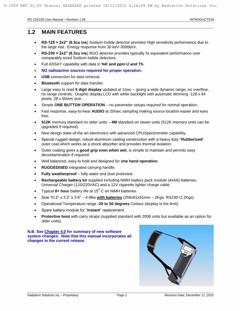
1.2 MAIN FEATURES
RS-125 = 2x2” (6.3cu ins) Sodium-Iodide detector provides High sensitivity performance due to the large xtal. Energy response from 30 keV-3000keV.
RS-230 = 2x2” (6.3cu ins) BGO detector provides typically 3x equivalent performance over
comparably sized Sodium-Iodide detectors.
Full ASSAY capability with data in %K and ppm U and Th.
NO radioactive sources required for proper operation.
USB connection for data retrieval.
Bluetooth support for data transfer.
Large easy to read 5 digit display updated at 1/sec – giving a wide dynamic range, no overflow, no range controls. Graphic display LCD with white backlight with automatic dimming -128 x 64 pixels, 28 x 60mm size.
Simple ONE BUTTON OPERATION – no parameter setups required for normal operation.
Fast response, easy-to-hear AUDIO at 20/sec sampling making source location easier and eyes
free.
512K memory standard on older units – 4M standard on newer units (512K memory units can be upgraded if required).
New design state-of-the art electronics with advanced CPU/spectrometer capability.
Special rugged design, robust aluminum casting construction with a heavy duty “Rubberized”
outer coat which works as a shock absorber and provides thermal isolation.
Outer coating gives a good grip even when wet, is simple to maintain and permits easy decontamination if required.
Well balanced, easy to hold and designed for one hand operation.
RUGGEDISED integrated carrying handle.
Fully weatherproof – fully water and dust protected.
Rechargeable battery kit supplied including NiMH battery pack module (4xAA) batteries, Universal Charger (110/220VAC) and a 12V cigarette lighter charge cable.
Typical 8+ hour battery life at 150 C on NiMH batteries.
Size 10.2” x 3.2” x 3.6” – 4.4lbs with batteries (259x81x91mm – 2Kgs: RS230=2.2Kgs).
Operational Temperature range -20 to 50 degrees Celsius (display is the limit).
Spare battery module for “instant” replacement.
Protective boot with carry straps (supplied standard with 2008 units but available as an option for
older units).
N.B. See Chapter 4.0 for summary of new software system changes. Note that this manual incorporates all changes in the current release.
D-1009 REV 01.05 Status: RELEASED printed 18/12/2015 5:26:09 PM by Radiation Solutions Inc.

RS-125/230 User Manual – Revision 1.05 SYSTEM OPERATION
Radiation Solutions Inc – Proprietary Page 3 Revision Date: December 11, 2015
2.0 SYSTEM OPERATION
2.1 BATTERIES
a) LOAD BATTERIES in HOLDER - the unit is shipped with the batteries separate. Remove the Battery Cover by depressing the Battery Cover Clip at each side. Load the 4 x AA cells with negative at the spring end. Slide the battery Cover back in place ensuring that the side guides are lined up – if all OK the Cover should fit smoothly on.
b) LOAD BATTERIES in UNIT – slide the Battery Holder into
the base of the RS-125 with the battery Terminals on the side of the copper terminals in the unit. (if in incorrectly the unit will not power on). If all is OK the 2 side mounted clips should “click” into place to hold the Battery Pack solidly into the RS-125 unit.
THE RS-125 / 230 ARE SHIPPED WITH CHARGED BATTERIES. HOWEVER OVER A PERIOD OF TIME THESE BATTERIES WILL DISCHARGE SO USER ARE ADVISED TO FULLY CHARGE BATTERIES BEFORE USE (4hrs MINIMUM).
2.2 BUTTON
The RS-125 Super-Spec instrument has only ONE control that is the front panel PUSH-BUTTON referred to as BUTTON. This Button is actually mounted on the face of the instrument but with the normal handle attached, connection to the Button is via a mechanical link from the Button on the handle.
The Button has 2 primary actions:
- CLICK – This is a click (SHORT) and release (less than 1 second button action).
- LONG – This is a click (LONG) and hold action typically held for 3 seconds with display feedback.
2.3 DISPLAY
The Display is a back lighted LCD display optimized for high contrast in outdoor conditions. Display Backlighting is required in low light conditions to make the display readable but this reduces battery life so to optimize battery life the backlighting automatically comes on ONLY when required. The Display is used for various functions and messages.
Battery Cover
clip
Battery
Holder
Battery
Terminal
Battery
Cover
D-1009 REV 01.05 Status: RELEASED printed 18/12/2015 5:26:09 PM by Radiation Solutions Inc.

RS-125/230 User Manual – Revision 1.05 SYSTEM OPERATION
Radiation Solutions Inc – Proprietary Page 4 Revision Date: December 11, 2015
2.4 POWER ON after BATTERY CHANGE
Press the BUTTON until the unit beeps then release the BUTTON. The battery change label is shown. The next display requires battery type selection.
NOTE: The Battery Type selection is required to let the unit know which batteries are used. Battery discharge rates vary between battery type so that for Low Battery detection it is essential the unit knows the correct battery selection. Normally RECHARGEABLE batteries are the correct option for the RS-125 as this is what is supplied with the unit – but the user can select to suit their requirements.
CAUTION: USERS SHOULD BE CAREFUL NOT TO LOAD non-RECHARGEABLE BATTERIES
SUCH AS ALKALINE, INTO THE UNIT WHEN CHARGING THEM. EVEN THOUGH THE UNIT IS PROTECTED AGAINST THIS, EVENTUALLY THE ALKALINE BATTERIES WILL LEAK AND DAMAGE THE INSTRUMENT.
CLICK the BUTTON (short less than 1 second) to move between selections. Once the correct selection is highlighted hold the Button (LONG-CLICK) until the selection background changes – release the Button for the correct selection. The next display is the start-up display and shows for 3 seconds then changes to the SURVEY display (see Section 2.6 below).
NOTE: The software version will be 5v95 in this case.
2.5 POWER ON normal
Press the BUTTON until the unit beeps and the sign on display is seen, then release the BUTTON. After 3 seconds the sign on display changes to the SURVEY DISPLAY.
NOTE: The Version# is the installed software version of the unit. In any communication with RSI regarding system performance, it is very helpful to specify the SERIAL # and the SOFTWARE VERSION to enable better trouble shooting support.
D-1009 REV 01.05 Status: RELEASED printed 18/12/2015 5:26:09 PM by Radiation Solutions Inc.

RS-125/230 User Manual – Revision 1.05 SYSTEM OPERATION
Radiation Solutions Inc – Proprietary Page 5 Revision Date: December 11, 2015
2.6 SURVEY DISPLAY
The Survey Display is segmented as shown in the figure. Local Time: settable to Local Time in Parameter Setup – Section 3.1 Battery Status: an Icon that shows current status of the battery. ALKALINE batteries RECHARGEABLE batteries Total Count: current radiation level in counts/second units. Graph: the last 100 readings are shown in graphical form. The right hand reading is the oldest and the left hand is the latest. This helps the user to look for small changes they might have missed.
2.7 AUDIO
a) INTERNAL - the RS-125 has an audio speaker inside the unit. The audio system is activated when the radiation level gets above a certain internally computed Audio Threshold. Once the Audio Threshold is exceeded then the Audio INTENSITY will reflect the incoming count rate to provide a varying INTENSITY level that relates directly to count rate and therefore local radiation intensity.
In this manner a hands-free survey can be carried out that is usually highly recommended in many
field situations where often the eyes are selecting the terrain so, without proper audio feedback, some significant count levels could be missed if the eyes are distracted. The Audio system can be fine-tuned in Parameter setup if required.
b) BLUETOOTH AUDIO Since the unit has Bluetooth (BT) connectivity, a new feature is the ability to use a BT earphone
system for improved audio in very noisy areas (rivers, rain etc.) See section 3 below to activate the selected BT earphone system (the RS-125 assumes that VOLUME control is on the earphone as is normal on most units) – see section 4 for special parameter changes for Audio.
2.8 STABILIZATION
Spectrometer systems like the RS-125 use an integrated SPECTROMETER system to provide data for analysis of ASSAY results. The accuracy of these results is a function of many items but a very significant one is spectrometer stability. It is crucial that the system spectrometer maintains a stable operational mode independent of temperature etc. To provide accurate Assay data the spectrometer must be stabilized to also give data independent of local conditions that could affect the data. To achieve this, the RS-125 has a FULLY AUTOMATIC spectrum stabilization system integrated inside the unit that uses the low radiation levels from surrounding geology to perform this analysis. In principle the system accumulates spectra INTERNALLY while
D-1009 REV 01.05 Status: RELEASED printed 18/12/2015 5:26:09 PM by Radiation Solutions Inc.

RS-125/230 User Manual – Revision 1.05 SYSTEM OPERATION
Radiation Solutions Inc – Proprietary Page 6 Revision Date: December 11, 2015
the system is powered ON and once a high enough level has been achieved then a complex analysis takes place to determine the correct spectrum position. This analysis results in an error measurement that the system uses internally to correct these effects. Note that this process is completely independent of the user. Typical Automatic Stabilization takes 5-10 minutes depending on local conditions.
Once the system is fully stabilized a new icon appears on the display above the Battery icon to show the analysis is complete – see figure. The RS-125 can continue to be used in the SURVEY mode while this fully automatic process is carried out in the background.
If the system is NOT stabilized and the user attempts an Assay, an error message appears and the unit beeps 3 times. If the user ignores this warning, the Assay continues – note that under these conditions the quality of the Assay data is questionable as system Stabilization is incorrect so the data could be roughly OK if stab is close but really bad data if Stab is significantly in error. The stab status is shown on the data retrieved to the PC for data verification.
In previous software versions, Stabilization was inhibited during Assay to minimize data errors. However if users are taking repeated Assays this means that Stabilization will be suspended for a long period of time and during this period the system could drift causing significant data errors.
To prevent this happening in Ver. 5v95 the Stabilization accumulation of data is NOT interrupted by the Assay process.
In fact an auto correction is implemented so that if at the end of Assay a Gain correction is required, the system automatically computes the potential Gain error and corrects the data to minimize system errors.
In addition the unit beeps every time it stabilizes as a reminder to the user that all is well. This can be inhibited if judged to be a problem – contact RSI. See Appendix Z for Contact Information.
2.9 ACTION
The RS-125 only has one BUTTON as noted above. To achieve the required system functions CLICK (short) and a Menu appears. The user navigates up and down this menu using CLICK (short) and the highlighting moves with the selection. Once the selection is made, hold the Button until the background changes from Dark to Light (typically 2-3 secs) then release the Button to make the selection. Selections:
a) Assay – activates the ASSAY capability of the system (see Section 2.10 below)
b) Reacquire bg – rests system background (see Section 2.11 below)
c) Start recording – activates the RECORDING capability of the system (see Section 2.12 below)
d) Configuration – permits parameter changes (in firmware versions before ver. 5.19, parameter selection was accessed on power up but v5.19 has made setup easier) - (see Chapter 3.0 below)
e) Continue survey – this selection returns to the previous SURVEY display with NO change in background setup levels.
D-1009 REV 01.05 Status: RELEASED printed 18/12/2015 5:26:09 PM by Radiation Solutions Inc.

RS-125/230 User Manual – Revision 1.05 SYSTEM OPERATION
Radiation Solutions Inc – Proprietary Page 7 Revision Date: December 11, 2015
2.10 ASSAY
NOTE: THE DISPLAY MUST SHOW THE STAB ICON BEFORE THE ASSAY DATA IS VALID.
If ASSAY is attempted with incorrect Stabilization an error message will appear on the display and the unit will beep 5 times. Correct action is to press the button once to terminate the ASSAY and wait until the unit is stabilized (normally 2-5 mins max).
When the ASSAY selection is made the ASSAY mode starts and a new display is seen
Meas Time – When the sample starts, a preset Sample Time parameter shows the sample time on the right and a count up timer showing the sample progress on the left.
Once the first 30 secs sample point is reached an Assay result is shown. Each additional 30 secs the Assay data is recomputed and updated on the display.
For best accuracy the full count period should be permitted. However in very anomalous areas sample times as low as 60 seconds give very good data due to the large detector size.
Guidelines are:
60 secs – anomalous area – low quality data is fine – fast sampling is required to get maximum data for an area in a short period of time
120 secs – (DEFAULT) anomalous area – medium quality data is fine – fast sampling is
required to get maximum data for an area in a short period of time
180 secs – medium anomalous area – good quality data is required
240 secs – medium to low anomalous area – high quality data is required
300-1800 secs – low anomalous area – maximum quality data is required
Note if the sample period is set ABOVE 999 secs then for display limitation reason, the “Meas time” is shown as a % of completion starting at 0.1%.
FOR EASE OF USE THE SAMPLE PERIOD IS NORMALLY SET TO 120 secs AS THIS VALUE GIVES GOOD QUALITY DATA IN MOST CONDITIONS. See Chapter(s) 3 and 4 to change to suit users requirements.
At the end of the preset Assay period the sample stops and the audio continuously beeps to advise user of the end of sample. The user takes the unit and presses the Button to stop the audio and inspect the display results. Note the display top label now shows “ASSAY RESULTS”.
Note that the K data is shown in % and the U and Th data in ppm (parts/million – N.B. ppm/10,000=%). The Total Count is usually shown in DOSE units (Sv/ Gy, R) to give users an idea of the relevant Dose information and can be used as an overall indication of radiation intensity.
D-1009 REV 01.05 Status: RELEASED printed 18/12/2015 5:26:09 PM by Radiation Solutions Inc.

RS-125/230 User Manual – Revision 1.05 SYSTEM OPERATION
Radiation Solutions Inc – Proprietary Page 8 Revision Date: December 11, 2015
The user can then view/note these results then press the BUTTON again and the display shows:
The user has approximately 3 secs to note the TIME or the Spectrum # to enable them to relate the stored data to the actual sample location when data is retrieved from the unit. Alternatively the user can note the TIME on the RS125 display BEFORE the sample is started as perhaps an easier way to record the data results relationship to sample location. The data is stored in system memory and can be retrieved later (see Section 4). NOTE: when the unit is initially setup the first spectrum is #0, after that they increment 1, 2, 3 etc. Even when data is erased this continues so if the last spectrum of the day was #46 then the first spectrum of the next day could be #47 the next #48 etc. This number continues to increment indefinitely so identical sample #’s cannot occur. This method of “universal spectrum numbering” helps in minimizing data confusion.
SHORTEN ASSAY PERIOD
At any time AFTER THE FIRST 30 SECS - the user can stop the Assay progress by a short CLICK of the Button – the display then shows the Assay Results with the time shown at whatever it stopped at. This is NOT recommended as the quality of the data depends a lot on the sample time.
Selecting a fixed sample time (usually 120 seconds) and ensuring all users wait for full sample completion, is a sensible way to maintain overall data quality.
DATA MEMORY LIMITS: Refer to section 4 (MEMORY) to determine system memory limitations and selections. The user is recommended to download data each day to prevent data loss.
GPS with ASSAY
If a GPS unit is configured (linked) to the RS unit then GPS location data is recorded at the end of the Assay period. To conserve GPS battery power it is only necessary for the GPS to be powered ON for a short time during the Assay sample period. To assess this – at the start of Assay power the GPS to ON and there should be a flashing cross-hair below the battery icon. Once the GPS has a good lock on satellite data, the cross-hair goes steady. As soon as this steady-state is seen the GPS coordinated have been transmitted to the RS unit so the GPS can now be powered OFF. Of course the GPS can stay on at all times if battery conservation is not a problem.
SPECIAL FUNCTIONS – see Section 4.5.5 Settings - Measurement for special Assay actions.
2.11 Reacquire Bg
When in the SURVEY mode of operation, the AUDIO THRESHOLD is set using a preset parameter – usually 1 Sigma for Geophysical application. When the unit is powered on, after internal checks the first 3 x 1 second samples are averaged and the Audio Threshold computed from this average – then the Audio is enabled. If the count level exceeds this threshold the audio sounds as described above. However in many areas the
local background changes and this causes threshold problems.
As an example if the local background level was 100 cps then at 1 Sigma the Audio Threshold = 110 cps (100 + 1 Sigma). So if the count rate goes above 110 cps the audio will sound. However if the local Background increases substantially to 300 cps then the audio will be on continuously and the audio will not seem as sensitive to small local changes. Similarly if the local Background goes down to 50 cps then the local radiation would
D-1009 REV 01.05 Status: RELEASED printed 18/12/2015 5:26:09 PM by Radiation Solutions Inc.

RS-125/230 User Manual – Revision 1.05 SYSTEM OPERATION
Radiation Solutions Inc – Proprietary Page 9 Revision Date: December 11, 2015
have to increase very substantially before the audio sounds – thus effectively desensitizing the audio system.
To overcome this “problem” AT ANY TIME the user can briefly touch the BUTTON and select the Reacquire bg selection. Then the system will return to the SURVEY display and the system will automatically recompute the Audio Threshold and the message “UPDATING BACKGROUND” will be seen on the display for the 3 seconds of the update. This means the user can “retune” the Audio Threshold at any time thus keeping the audio threshold optimized.
2.12 Start RECORDING
The RS-125/230 now has a RECORDING capability that permits automatic recording of TOTAL COUNT data and/or ASSAY RESULTS into memory to permit line profiles etc. In addition an external GPS unit can be interfaced directly into the unit via the Bluetooth connection and the GPS data integrated directly into the internally stored data memory.
NOTE: MEMORY – system memory is allocated to suit users requirements. (See Section 4.5.5.3 for details and changes).
a) RECORDING WITH GPS
The system has been developed to work with Bluetooth (BT) GPS and communicates data directly to the RS-125/230 unit(s). However the GPS output data stream NMEA (GGA format) is common to all units so other GPS units should also work.
GPS INITIALIZATION
Setup the GPS recording link as described below in Section 3. Once the GPS is activated (linked) to the RS-125/230, data recording can start.
From the Main Menu select “Start recording” and new icons appear on the display as shown in the figure.
The “R” symbol shows that recording is ON and the cross-hairs show the GPS connection. If the cross-hair symbol is flashing this means that the GPS has not found a good satellite lock so data recorded in the system for Lat/Long are ZERO. When the GPS acquires satellites the cross-hair is solid showing proper location data is being recorded.
NOTE: When the GPS is activated it does nothing until the START RECORDING selection is made. Then the unit starts to automatically acquire satellites to get a good lock. It is very common that it takes 5-10 minutes to get a good lock with as many satellites as are available (this is the equivalent of a cold start. Once it has found ALL the satellites available it only needs 3 to get a good position. This means that once it has got all the satellites available it can continue to give good data even in areas where many satellites are lost.
c) WITHOUT GPS
If no GPS is connected or activated Profile recording can still occur. From the Main Menu select “Start recording” and new icons appear on the display as shown in the figure. The “R” symbol shows that recording is ON and the flashing GPS cross-hairs still appears but may be ignored.
c) STOP RECORDING
From the Main Menu select “Stop recording” and the record icon will disappear, the flashing GPS cross-hairs still appear but may be ignored.
D-1009 REV 01.05 Status: RELEASED printed 18/12/2015 5:26:09 PM by Radiation Solutions Inc.

RS-125/230 User Manual – Revision 1.05 SYSTEM OPERATION
Radiation Solutions Inc – Proprietary Page 10 Revision Date: December 11, 2015
2.13 DATA RECORDING GENERAL
The data recording action, when the symbol is shown means that the selected data is being recorded.
Section 2.13.a), b), & c) below permits the user to select whether to record TOTAL COUNT data only, ASSAY RESULTS only or both.
a) TOTAL COUNT data only
Set parameters as required:
RECORD TYPE = Total only
Total scan period = 1- 20 secs (e.g.1 sec)
MEMORY allocation as in section 4, selected to
suit recording needs.
When START RECORDING is selected then Total Count data is stored in memory at the selected rate (Total scan period) of 1 sample/sec (or as selected).
The data is stored in 30 sample data blocks. If an external GPS is integrated, the GPS data is stored every 30 samples – if no GPS is connected the GPS data is stored as zeros.
Some users want to record GPS data at a faster data rate. This can be done but some memory gets sacrificed – see Appendix B.
When data recording is complete press the Button to see the menu and select Recording OFF to terminate recording.
RS-Analyst is used to retrieve this profile data see section 4 for more details.
b) ASSAY RESULTS data only
User must select:
RECORD TYPE = Assay only
Assay scan period = 30-1800 secs (e.g. 30 sec)
MEMORY allocation – as described in section 4.9
Parameter setup can be done manually as described in Chapter 3.0 but it is much easier to do via PC connection as shown in Chapter 4.0.
When START RECORDING is selected then Assay Results only (no spectra) data is going into memory at the selected rate of 30 secs/sample.
The data is stored in a txt file, if an external GPS is integrated the GPS data is also stored – if no GPS is connected the GPS data is stored as zeros.
When data recording is complete press the Button to see the menu and select Recording OFF to terminate recording.
RS-Analyst is used to retrieve this profile data as shown below in a space delimited file that can be read into Excel as required – see Chapter 4.0 for more details.
c) TOTAL + ASSAY data
In this case BOTH the Total Count + GPS data and the Assay Results + GPS data are stored in their appropriate memory locations and can be retrieved as described in Appendix A.
R
D-1009 REV 01.05 Status: RELEASED printed 18/12/2015 5:26:09 PM by Radiation Solutions Inc.

RS-125/230 User Manual – Revision 1.05 SYSTEM OPERATION
Radiation Solutions Inc – Proprietary Page 11 Revision Date: December 11, 2015
NOTE: Customers Recording Data in OnTheFly Assay mode may find that if the device had been previously setup for Record Mode that the sequential order or chronological numbering for saved files will be affected, as the device is also storing data for OnTheFly storage. It appears that the sequential numbering is skipping as the device is storing data on the fly. Each Record assay and OnTheFly assay is assigned a unique ID. From affected customer`s data it appears that assays were being saved while the “OnTheFly” option was started. In this case the unit would assign an ID to the Manual (Record) assay and skip the OnTheFly assay, thus resulting in non-sequential ID numbering. To prove this is happening compare the time stamps of the exported “Manual assay” data and the “OnTheFly assay” data. When you export the data the “OnTheFly assays” will be the ones that have a blank space in the total column while the Manual assays will contain all the data.
2.14 POWER OFF
To power OFF the unit, press and hold the BUTTON and the unit powers OFF. The display shows a countdown “TURNING OFF 3”, “TURNING OFF 2”, “TURNING OFF 1” then the unit finally powers off. Sometimes this countdown sequence can take a few seconds before initiating if the unit is “busy” but typically no more than 5 seconds before the countdown sequence starts. If the BUTTON is released at any time before power OFF, the unit will continue to function.
2.15 LOW BATTERY
If the Batteries are getting low, an audio beep prompts the user to view the display. If the Battery icon shows very little battery left the battery pack should be changed. RSI recommends that a spare Battery Pack is carried at all times to prevent field problems as changing is a few seconds task with NO loss of stored data.
Two battery modules are supplied with each unit.
D-1009 REV 01.05 Status: RELEASED printed 18/12/2015 5:26:09 PM by Radiation Solutions Inc.

RS-125/230 User Manual – Revision 1.05 SYSTEM OPERATION
Radiation Solutions Inc – Proprietary Page 12 Revision Date: December 11, 2015
This Page is intentionally left Blank.
D-1009 REV 01.05 Status: RELEASED printed 18/12/2015 5:26:09 PM by Radiation Solutions Inc.

RS-125/230 User Manual – Revision 1.05 CONFIGURATION (Manual Method)
Radiation Solutions Inc – Proprietary Page 13 Revision Date: December 11, 2015
3.0 CONFIGURATION (Manual Method)
(Chapter 4.0 shows a much simpler way of parameter changes via the PC) Select CONFIGURATION for the display reached by clicking BUTTON.
a. CLICK (short press of the BUTTON) to move down the menu. The screen highlights the selection.
Move down the menu until the required parameter is reached then LONG CLICK (press BUTTON until the backlighting of the display changes from White figures on a Black background to the opposite) – then release the BUTTON to select this parameter.
b. Once the parameter is selected use CLICK (short BUTTON) to
move down the menu selection. Once the correct one is reached LONG CLICK (hold BUTTON until the background changes) then release the BUTTON to select.
3.1 Configuration (PARAMETERS)
a. DATE and TIME
i. YEAR - YEAR for the internal CLOCK. The display shows 2006, 2007, 2008 etc. CLICK to select the right YEAR then LONG-CLICK to set this selection.
ii. MONTH - this sets the MONTH for the internal CLOCK. The display shows Apr, May, Jun etc. CLICK to select the right MONTH then LONG-CLICK to set this selection.
iii. DAY - this sets the DAY (DATE) for the internal CLOCK. The display shows 1, 2, 3 ……31. CLICK to select the right DAY then LONG-CLICK to set this selection.
iv. HOUR – this sets the HOUR for the internal CLOCK. The display shows 0,1,2,3…23. CLICK to select the right HOUR then LONG-CLICK to set this selection.
v. MINUTE - this sets the MINUTES for the internal CLOCK. The display shows 0,1,2,3…59. CLICK to select the right MINUTE then LONG-CLICK to set this selection.
vi. GO BACK – return to the Configuration menu.
D-1009 REV 01.05 Status: RELEASED printed 18/12/2015 5:26:09 PM by Radiation Solutions Inc.

RS-125/230 User Manual – Revision 1.05 CONFIGURATION (Manual Method)
Radiation Solutions Inc – Proprietary Page 14 Revision Date: December 11, 2015
b. DISPLAY
i. CONTRAST sets the Display CONTRAST. Selections are -3, -2, -1, 0, 1, 2, 3. -3 to -1 lightens the display, +1 to +3 darkens it. Normally “0” is a good average selection. CLICK to select the right setting then LONG-CLICK to set this selection.
ii. BACKLIGHT – this sets the Display BACKLIGHT.. Selections are AUTO, ON, OFF.
AUTO = the system automatically selects the required Backlighting using a light sensor to set the required level. This is the best selection but in dark shadow areas the Backlighting will come ON to make the display more visible. While often this is a required feature the downside of this is a significant reduction in battery life by typically 40% if the Backlighting is ON all the time.
ON = overrides the light sensor and sets the Backlighting ON all the time.
OFF = sets the Backlight permanently Off to conserve battery life.
iii. GO BACK – return to the Configuration menu.
c. AUDIO
i. VOLUME - this enables or disables the audio survey system. Selections are ON, OFF
ON = Audio is enabled
OFF = Audio is disabled
For Geophysical applications set to ON as Audio Survey is an essential operational requirement, the OFF mode is used for special applications
ii. FILTER LENGTH – this sets the filtering parameters to optimize the audio system response for different applications. Selections are 1-10 and indicate the number of 50mS samples are averaged.
1 = shortest filter thus the fastest audio response
10 = longest filter giving the slowest response
SHORT filters give fast response but don’t give such a “smooth” response to a slowly increasing field.
LONG filters give a very smooth “even” response for a slowly moving field but tend to minimize short term local effects
D-1009 REV 01.05 Status: RELEASED printed 18/12/2015 5:26:09 PM by Radiation Solutions Inc.

RS-125/230 User Manual – Revision 1.05 CONFIGURATION (Manual Method)
Radiation Solutions Inc – Proprietary Page 15 Revision Date: December 11, 2015
For most Geophysical applications a setting of “9” is appropriate
iii. THRESHOLD - this sets the Audio response threshold. Selections are 1x to 5x Sigma levels of the average of the first 3 samples. If 3 Sigma is selected then when the unit starts the local radiation BACKGROUND is averaged for a 3 second period (display shows Updating Background).
This local background average is then used to compute the selected 3 Sigma (3 Standard deviations) level and this is ADDED to the average background to set the AUDIO THRESHOLD. Each new radiation sample (at a 20/sec rate) are tested against this AUDIO THRESHOLD and if above it then the audio sounds.
As an example – a typical local background level could be 100 cps (counts/second). So a selection of 3 Sigma would set the Audio Threshold = 100 + 3 x Sq Rt of 100 = 100+30=130. So if the count level goes above 130cps the audio will sound.
Once the Audio Threshold is exceeded; then the Audio INTENSITY will reflect the incoming count rate to provide a varying INTENSITY level, that relates directly to the count rate and therefore local radiation levels. In this manner a hands-free survey can be carried out that is usually highly recommended in many field situations where often the eyes are selecting the terrain, so without proper audio feedback some significant count levels could be missed if the eyes are distracted. For most GEOPHYSICAL applications, a 1 Sigma level is recommended and this is the DEFAULT setting. This means that occasionally the unit will “chirp” on local background but this is often comforting as a means of ensuring the unit is functioning.
In some other operational areas this random chirping can distract the user so for these SPECIAL applications a 3 Sigma level can be used.
CLICK to select the right setting then LONG-CLICK to set this selection.
iv. GO BACK – return to the Configuration menu.
d. MEASUREMENT
i. TOTAL SCAN PERIOD – the user selects the SCAN data rate for Recording Total Count data – selections are 1-20 secs – default = 1 sec
ii. TOTAL AVERAGING – this sets the filtering of the display numeric data. Selections are 1,2,3,4,5 and these are Moving Average parameters.
1 = NO filtering at all so numeric data is displayed as recorded – normally recommended for Geo users and the DEFAULT setting
3 = a 3 point filter so the numeric data displayed is a 3 point moving average updated at a 1/sec rate
5 = a 5 point moving average
In most Geophysical applications the user utilizes the AUDIO to find the approximate peak intensity location and the NUMERIC data to select
D-1009 REV 01.05 Status: RELEASED printed 18/12/2015 5:26:09 PM by Radiation Solutions Inc.

RS-125/230 User Manual – Revision 1.05 CONFIGURATION (Manual Method)
Radiation Solutions Inc – Proprietary Page 16 Revision Date: December 11, 2015
the actual hot-spot. In this application a setting of “1” gives the fastest response but the other settings are available as required.
iii. ASSAY TIME – the user selects the SCAN data rate for recording Assay Results data – selections are 30-1800 secs – default = 30 sec. Note that Assay auto scan SPECTRA are NOT stored in memory to conserve memory space however normal Assay still stores full spectral data.
iv. OnFlyAssay Window – sets the period in seconds that the On-the-fly Assay data is averaged for. Assay data below 20 secs is very noisy so normally this parameter should be set to a minimum of 30 (secs). Note that these data are computed as a running average on a 1/sec basis.
Thus when started, for the first 30 seconds no data is computed until this time period is achieved then a 30 second average is computed. This average is then updated at a 1/second rate and used as required.
v. OnFlyAssay storing – sets the period in seconds at which the On-the-fly Assay results computed as noted in (iv) above are stored in data memory during recording.
vi. Show OnFlyAssay – sets the period in seconds at which the On-the-fly Assay results computed as noted in (iv) above are displayed.
vii. RECORD TYPE – this selects the type of data recording method used when START RECORDING (SCAN mode) is selected. Also see MEMORY selection in Chapter 4.0.
- Only total – selection means that START RECORDING only stores TOTAL COUNT data and GPS.
- Only Assay – selection means that START RECORDING only stores ASSAY RESULTS data and GPS.
- Total+Assay – selection means that START RECORDING stores TOTAL COUNT + ASSAY RESULTS data and GPS.
viii. Show Dose – this allows the user the ability to show the DOSE RATE on the front display. Note the Dose Rate is computed from KUT data results and is referred to as the GEOPHYSICAL ASSAY. Users should note that if (for example) an artificial isotope such as Cesium-137 is placed near the unit, the Count rate will change as the system sees the radiation but the Dose Rate will be essentially unaffected as Cs-137 is outside the KUT calculation matrix.
ix. DOSE UNITS – user can select R, Gy or Sv as required.
x. GO BACK – return to the Configuration menu.
D-1009 REV 01.05 Status: RELEASED printed 18/12/2015 5:26:09 PM by Radiation Solutions Inc.

RS-125/230 User Manual – Revision 1.05 CONFIGURATION (Manual Method)
Radiation Solutions Inc – Proprietary Page 17 Revision Date: December 11, 2015
e. STABILIZATION
i. CS STABILIZATION – permits the user to carry out stabilization using a Cesium-137 source. This is a special capability sometimes useful if the unit has serious troubles.
It requires the availability of a Cesium-137 typically 1-10uCi spaced a few inches away from the face of the unit (1uCi against the face, 5uCi 2” away, 10uCi – 6” away is recommended). Once the source is positioned, activate the selection and the unit will stabilize itself automatically on the Cesium source. When it says COMPLETE, remove the source and carry on as usual. The advantage of this capability is that Cesium-137 is a very defined source so if the units stabilization is completely lost, the Cs stabilization can often fully recover it. Huge improvements to v5.19 firmware and following versions make this feature non-essential but under special circumstances it is useful. Consult RSI before using this feature if unsure.
ii. TEMP.RECOVERY – under special circumstances an abrupt change of temperature can sometimes make the Gain adjustment step computed by the automatic system stabilization fail, this is especially true of the BGO detector in the RS-230. To help the system recover if a unit will NOT stabilize within 5 minutes – select this Temp.recovery option. The unit will then reload the original calibration data at the factory corrected to the local temperatures. After this action the unit should stabilize OK.
f. ACCESSORIES
i. BATTERY TYPE – This sets the type of Battery used. Selections are “Non rechargeable” or “Rechargeable”
Non rechargeable = selects Alkaline non-Rechargeable batteries. It is highly recommended that if non-rechargeable batteries are used then ONLY ALKALINE batteries be chosen. Some non-Alkaline non-rechargeable batteries can leak and cause problems inside the instrument. If non-Alkaline are used then remove the battery clip after use to avoid this fairly common leak problem.
Rechargeable = the internal battery system will automatically select battery type so NiCd or NiMH batteries can be used. However NiMH batteries (2500 series) are highly recommended as NiCd batteries have significant operational limitations in prolonged use (also see Chapter 5.0).
ii. GPS - this selection is used to couple an external GPS to the system by Bluetooth (BT) link. The users’ manual of the GPS should be consulted to ensure that the unit batteries are charged. Once batteries are OK switch the units BT capability to ON.
NOTE: Not all GPS models were tested but most BT GPS models using GGA are expected to work.
Choose - Select GPS – display shows “Looking for Bluetooth devices” then various messages and finally the “Select GPS” display is seen. Use the Button to cursor down to select “Garmin GPS 10”, then LONG Button down until the reverse video changes to select the device. Message says “Connecting to device” and then finally “GPS connected” then the display goes back to the main menu. Exit the menu to go back to the Survey screen.
D-1009 REV 01.05 Status: RELEASED printed 18/12/2015 5:26:09 PM by Radiation Solutions Inc.
RS-125/230 User Manual – Revision 1.05 CONFIGURATION (Manual Method)
Radiation Solutions Inc – Proprietary Page 18 Revision Date: December 11, 2015
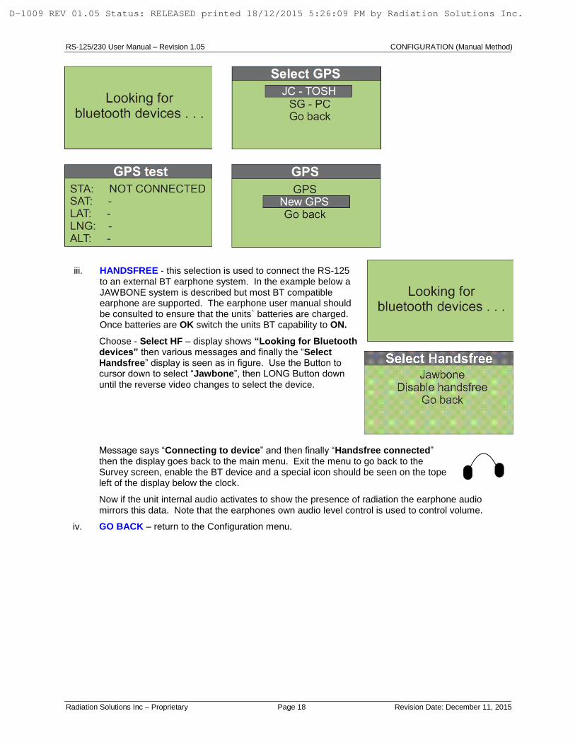
iii. HANDSFREE - this selection is used to connect the RS-125 to an external BT earphone system. In the example below a JAWBONE system is described but most BT compatible earphone are supported. The earphone user manual should be consulted to ensure that the units` batteries are charged. Once batteries are OK switch the units BT capability to ON.
Choose - Select HF – display shows “Looking for Bluetooth devices” then various messages and finally the “Select Handsfree” display is seen as in figure. Use the Button to cursor down to select “Jawbone”, then LONG Button down until the reverse video changes to select the device.
Message says “Connecting to device” and then finally “Handsfree connected” then the display goes back to the main menu. Exit the menu to go back to the Survey screen, enable the BT device and a special icon should be seen on the tope left of the display below the clock.
Now if the unit internal audio activates to show the presence of radiation the earphone audio mirrors this data. Note that the earphones own audio level control is used to control volume.
iv. GO BACK – return to the Configuration menu.
D-1009 REV 01.05 Status: RELEASED printed 18/12/2015 5:26:09 PM by Radiation Solutions Inc.

RS-125/230 User Manual – Revision 1.05 PC CONNECTIONS
Radiation Solutions Inc – Proprietary Page 19 Revision Date: December 11, 2015
4.0 PC CONNECTIONS
NOTE: The PC data retrieval and display program supplied to support the RS-xxx portable instruments is
being frequently updated to add user required features. RSI has discontinued supplying software on a CD as it quickly becomes obsolete. The latest software, firmware and documentation version is available from RSI – Contact RSI Service for the latest link to Firmware/Software upgrades (see Appendix Z for contact information).
NOTE: New versions of RSAnalyst may NOT be compatible with the current device firmware but the
Analyst PC Software update process also permits updates of the firmware inside the RS-125 or RS-230 as required. So the rule to update is – update BOTH the RSAnalyst PC Software and the unit’s internal FIRMWARE as detailed below.
NOTE: The RS-125 and RS-230 instrument(s) is a joint development of RSI and our sister company
GEORADIS so some software screens may be labeled GEORADIS as required.
4.1 PC SOFTWARE DOWNLOAD
Setup a new sub-directory on the USER PC – named as required - (e.g. RSI). Click on the link sent to you by RSI Service (see Appendix Z for contact information). Choose SAVE when requested, then select the correct sub-directory to download the software to (e.g. RSI). Then open this file and UNZIP it as required.
4.2 INSTALL RSAnalyst
NOTE: This software has been designed to run on all current Microsoft OS systems. The software has been successfully installed and heavily tested on a variety of computers including Win2000, WinXP, WinXP Professional, Vista and System 7. A minority of users have experienced installation problems, concerning computer setup configurations. If these problems persist, contact RSI for support.
Use Windows Explorer to look at the sub-directory
where the downloaded file exists (e.g. RSI) – locate the file named INSTALL.EXE. Double click this file then select RUN.
When this screen is seen – click “Install Georadis
RSAnalyst”.
D-1009 REV 01.05 Status: RELEASED printed 18/12/2015 5:26:09 PM by Radiation Solutions Inc.

RS-125/230 User Manual – Revision 1.05 PC CONNECTIONS
Radiation Solutions Inc – Proprietary Page 20 Revision Date: December 11, 2015
Follow prompts to complete installation. N.B. Users requiring USB connection (as opposed to Bluetooth) should then go back to the selection menu and select “Install Georadis USB driver”. When this is complete select EXIT to terminate the process.
Then FINISH to complete the final installation. The process is now complete and a new icon is located on the Windows Desktop
D-1009 REV 01.05 Status: RELEASED printed 18/12/2015 5:26:09 PM by Radiation Solutions Inc.

RS-125/230 User Manual – Revision 1.05 PC CONNECTIONS
Radiation Solutions Inc – Proprietary Page 21 Revision Date: December 11, 2015
NOTE: ONCE THE NEW RS-ANALYST IS INSTALLED - USERS ARE STRONGLY ADVISED TO UPGRADE THE SYSTEM FIRMWARE TO IMPLEMENT BUG FIXES AND NEW FEATURES. HOWEVER WHEN THIS IS DONE ALL DATA IN THE UNIT IS ERASED! USERS SHOULD RETRIEVE STORED DATA FROM THE UNIT BEFORE UPGRADING.
4.3 STARTUP RSAnalyst
The system stores all data in a Firebird database and this may be created upon startup.
Double-click the RS-Analyst icon on the desktop. The No database message is displayed – click YES, choose the sub-directory (e.g. RSAnalyst and choose a database name (e.g. Data).
A Firebird formatted data base will be set up named DATA on the RSI sub-directory and all data will be stored there until a different database is created.
The screen will then
open the page as displayed: Current Database will be shown here:
D-1009 REV 01.05 Status: RELEASED printed 18/12/2015 5:26:09 PM by Radiation Solutions Inc.

RS-125/230 User Manual – Revision 1.05 PC CONNECTIONS
Radiation Solutions Inc – Proprietary Page 22 Revision Date: December 11, 2015
4.3.1 RSAnalyst SYSTEM SOFTWARE
4.4 MAIN MENU
4.4.1 FILE
- Create local data base – select this to create a new Database stored in a required location with a selected name as needed.
- Open local database – permits users to select a local data base that already exists and add data to it.
- Create remote database – select this to create a new Database stored remotely with a selected name as needed.
- Open remote database – permits users to select a remote data base that already exists and add data to it.
NOTE: A single database can support many RS-121 units with data selection using the units’ serial number.
Quit – Stop program, a requestor will be displayed for user confirmation.
MAIN MENU - Section 4.4 TOOL BAR – Section 4.5
PAGE TABS – Section 4.6
STATUS BAR – Section 4.7
D-1009 REV 01.05 Status: RELEASED printed 18/12/2015 5:26:09 PM by Radiation Solutions Inc.

RS-125/230 User Manual – Revision 1.05 PC CONNECTIONS
Radiation Solutions Inc – Proprietary Page 23 Revision Date: December 11, 2015
4.4.2 DEVICE
See the TOOL BAR for information on the Device Special functions. The following special functions are repeated in the Tool Bar; Connect device – Disconnect device – Download data – Device settings –
4.4.3 PROGRAM
See the TOOL BAR for information on the Program Special functions. The following special functions are repeated in the Tool Bar; Options – About –
4.5 TOOL BAR
4.5.1 CONNECT:
Connection of the RS-125/230 unit to the PC system can either be made by local USB connection or via Bluetooth (BT).
a) Connection Via USB - connect the supplied USB cable, plug the USB connector into the unit below the rubber flap at the end.
With the RS-230 unit powered ON and the RS-Analyst program displayed on the PC.
Click this icon to establish a connection.
The unit’s serial number will be shown in a data box (e.g. 2025) – click OK.
“Connected device #2025” will be displayed on the Status bar - bottom left on the PC screen, and a USB icon will be shown on the RS unit.
The unit is now fully connected.
D-1009 REV 01.05 Status: RELEASED printed 18/12/2015 5:26:09 PM by Radiation Solutions Inc.

RS-125/230 User Manual – Revision 1.05 PC CONNECTIONS
Radiation Solutions Inc – Proprietary Page 24 Revision Date: December 11, 2015
b) Connection Via BLUETOOTH (BT)
NOTE: All except the early RS units have BT capability – however in the early units the software did not support this BT technology. In the latest software 5vXX this BT is fully supported. Users are advised that if they need BT capability, then install the new v5xx software included in the download package using the USB connectivity THEN test the BT to be sure all is OK. Contact RSI if you have problems problems.
Typically data transfer is 3x faster using USB
connections.
The following is a typical Windows XP setup. User setup may slightly differ depending on the Operating System but in principle the connection linkage is the same.
Power ON the RS-121 unit and place it within 1m of the PC being used.
On the PC select START – All Programs – Bluetooth – Wireless Data Transfer.
This display appears as the unit searches for BT devices nearby.
This display shows the unit has been found. Click the box (green check sign in the picture). Close this window (red X at top right of the box) At the bottom right tray the BT sign will be seen; – right click on this and select Bluetooth settings.
A new display is seen click DETAILS (sometimes a BT Password is asked for – if required enter 0 0 0 0)
Inspect the second display for
PORT NAME – in this case COM40.
D-1009 REV 01.05 Status: RELEASED printed 18/12/2015 5:26:09 PM by Radiation Solutions Inc.
RS-125/230 User Manual – Revision 1.05 PC CONNECTIONS
Radiation Solutions Inc – Proprietary Page 25 Revision Date: December 11, 2015
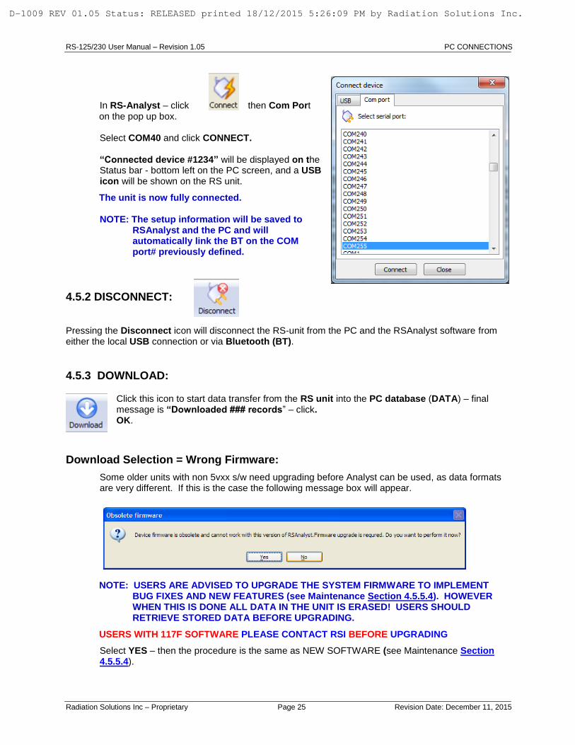
In RS-Analyst – click then Com Port on the pop up box.
Select COM40 and click CONNECT. “Connected device #1234” will be displayed on the
Status bar - bottom left on the PC screen, and a USB icon will be shown on the RS unit.
The unit is now fully connected.
NOTE: The setup information will be saved to RSAnalyst and the PC and will automatically link the BT on the COM port# previously defined.
4.5.2 DISCONNECT:
Pressing the Disconnect icon will disconnect the RS-unit from the PC and the RSAnalyst software from either the local USB connection or via Bluetooth (BT).
4.5.3 DOWNLOAD:
Click this icon to start data transfer from the RS unit into the PC database (DATA) – final message is “Downloaded ### records” – click. OK.
Download Selection = Wrong Firmware:
Some older units with non 5vxx s/w need upgrading before Analyst can be used, as data formats are very different. If this is the case the following message box will appear.
NOTE: USERS ARE ADVISED TO UPGRADE THE SYSTEM FIRMWARE TO IMPLEMENT BUG FIXES AND NEW FEATURES (see Maintenance Section 4.5.5.4). HOWEVER WHEN THIS IS DONE ALL DATA IN THE UNIT IS ERASED! USERS SHOULD RETRIEVE STORED DATA BEFORE UPGRADING.
USERS WITH 117F SOFTWARE PLEASE CONTACT RSI BEFORE UPGRADING
Select YES – then the procedure is the same as NEW SOFTWARE (see Maintenance Section 4.5.5.4).
D-1009 REV 01.05 Status: RELEASED printed 18/12/2015 5:26:09 PM by Radiation Solutions Inc.

RS-125/230 User Manual – Revision 1.05 PC CONNECTIONS
Radiation Solutions Inc – Proprietary Page 26 Revision Date: December 11, 2015
4.5.4 OPTIONS:
ADDING COMMENTS/NOTES
A special feature of RSAnalyst is the ability to mark data on the display to add comments related to the data.
Record Description:
Select NEW FIELD –
The selections are: Integer, Real Number and String.
Choose FIELD TYPE on this data box. Select STRING as this gives a large space for comments – then NEXT.
Then enter in a FIELD NAME (e.g. Comments)
then a Field Description (e.g. Comments) and click ADD FIELD.
D-1009 REV 01.05 Status: RELEASED printed 18/12/2015 5:26:09 PM by Radiation Solutions Inc.

RS-125/230 User Manual – Revision 1.05 PC CONNECTIONS
Radiation Solutions Inc – Proprietary Page 27 Revision Date: December 11, 2015
Edit Field – This will open the Field Property dialog box for the selected field.
Move Up – This will move the field up one in the listing.
Move Down – This will move the field down one in the listing.
Delete Field – This will remove the field from the list.
Graph Units:
Dose Units can be selected from a drop-down menu.
The selections are: nGy/h, nSv/h and µR/h. This will set the Dose Unit for the charts.
D-1009 REV 01.05 Status: RELEASED printed 18/12/2015 5:26:09 PM by Radiation Solutions Inc.

RS-125/230 User Manual – Revision 1.05 PC CONNECTIONS
Radiation Solutions Inc – Proprietary Page 28 Revision Date: December 11, 2015
Language: Thirty-four languages are supported and can be selected from a drop-down menu. English is the
default language. This window allows the User to setup the language used for menus and instructions.
4.5.5 SETTINGS:
Selecting this icon opens the Device Settings and Maintenance Window. The window has the following tabs: Device Setting, Stabilization Log, Memory and Maintenance.
4.5.5.1 DEVICE SETTINGS - TAB
The Device Settings window is a User Set of parameters as shown here. The Window has four tabs; Display, Audio, Memory and Accessories.
DISPLAY:
Contrast = adjusts display contrast – range +3 > -3 - normally 0
Backlight = backlight options – selection – ON, OFF, AUTO - normally Auto
D-1009 REV 01.05 Status: RELEASED printed 18/12/2015 5:26:09 PM by Radiation Solutions Inc.

RS-125/230 User Manual – Revision 1.05 PC CONNECTIONS
Radiation Solutions Inc – Proprietary Page 29 Revision Date: December 11, 2015
AUDIO:
Audio volume = selections ON, OFF - usually ON (permits muting if required).
Audio filter length = permits audio response adjustments by filtering changes – for Geophysics usually 9
Audio threshold = selections x1 to x6 sigma – for Geophysics usually 1x sigma.
MEASUREMENT:
Total scan period – the sample period (minimum 1 sec) for K/U/T/Total data to be stored on the RECORDING (SCAN) mode described above – usually 1 sec for fast surveys or 2-5 secs for slower traverses
Total averaging = permits the front panel instrument display to use running averaging to “smooth” data viewing – for Geophysics usually 1
Assay time = sets the time period used when an ASSAY is taken - selection 30-1,800 secs - 120 secs is a sensible selection under most conditions
On-fly assay window = the sample period (30 - 300 secs) for Assay data to be computed on the RECORDING (SCAN) mode described above – usually 30 secs. This is really a moving average period updated at 1/sec
D-1009 REV 01.05 Status: RELEASED printed 18/12/2015 5:26:09 PM by Radiation Solutions Inc.

RS-125/230 User Manual – Revision 1.05 PC CONNECTIONS
Radiation Solutions Inc – Proprietary Page 30 Revision Date: December 11, 2015
On-fly assay store time = the sample period (10 - 300 secs) for Assay data to be stored on the RECORDING (SCAN) mode described above – usually 30 secs but some users want faster data
storage so this parameter can be set to 10 secs if required
Show on fly assay – YES or NO. If YES is selected then during recording the main data display screen changes to show real-time Assay on the fly.
Record type = permits data selected in RECORDING (SCAN) mode - selections:
- only SURVEY – only Total Count at the selected rate
- only ASSAY – only Assay data at the selected rate
- both SURVEY and ASSAY – both data sets at the selected rates
NOTE: Ensure MEMORY selection is adjusted correctly to permit the required amount of data recording space – see Section 4.5.5.3 for more information.
Dose rate units = selects the Dose units used in the “Total” display on the units display during
Assay.
Selections are:
- R – Exposure Rte
- Gy – Absorbed Dose
- Sv – Dose Equivalent
Action after assay – normally set to Save Immediately.
Show dose rate – normally set to Yes.
Record after startup – normally set to NO. If YES then when the unit is powered ON, it immediately
enters the Scan mode (same as selecting Start Recording from the main unit’s menu).
ACCESSORIES:
Battery type = none-rechargeable or rechargeable - usually rechargeable.
GPS PIN – some GPS units require a PIN number for handshaking
Mute buzzer when HF – if selected the Audio buzzer in the instrument is muted when the BT Headphone is selected.
Synchronize time with PC = if this box is checked then the PC will sync the time of the RS unit to the current setting on the PC.
PARAMETER CHANGE:
Under special conditions some internal parameters of the unit may need to be adjusted. If
D-1009 REV 01.05 Status: RELEASED printed 18/12/2015 5:26:09 PM by Radiation Solutions Inc.

RS-125/230 User Manual – Revision 1.05 PC CONNECTIONS
Radiation Solutions Inc – Proprietary Page 31 Revision Date: December 11, 2015
this is required RSI will send the user a special file with these parameter changes embedded. To load this file click the Load Parameters from File button then selecting the appropriate file and follow the prompts.
In addition users can save a copy of the parameter file by clicking on the Save Parameters to File button or read in a new one with special parameter settings as required.
Press Write Parameters to device to load these settings into the unit (also see Section 4.5.5.4 )
4.5.5.2 STABILIZATION LOG
This tab selection permits users to access the internal Stabilization records of the unit. If the unit is acting incorrectly it is possible that the stabilization is causing problems. This selection permits the Stab Log to be downloaded and viewed (Download Log) or more useful is (Export Log) which outputs the data into a text file which can be exported and then emailed to RSI for analysis.
4.5.5.3 MEMORY
The RS series of units were initially released with 512K and later 2Mb of memory but all units are currently shipped with 4Mb of memory. Older units can be upgraded to 4Mb if required at a nominal fee. In v5.xx s/w the available memory can be allocated to the various functions and this is done inside RSAnalyst. NOTE: the memory can be re-allocated at any time but this re-allocation ERASES ALL DATA IN MEMORY so users should download any data before allocation is attempted.
D-1009 REV 01.05 Status: RELEASED printed 18/12/2015 5:26:09 PM by Radiation Solutions Inc.

RS-125/230 User Manual – Revision 1.05 PC CONNECTIONS
Radiation Solutions Inc – Proprietary Page 32 Revision Date: December 11, 2015
READ OCCUPIED SPACE – shows how much memory is currently in use.
CLEAR MEMORY – this command is used to clear data memory once data has been transferred to the PC – most users transfer data daily then clear the memory to minimize data confusion and in low memory units. CREATE NEW MEMORY LAYOUT – this command allows the users to set the memory to suit their application – refer to the tables below for information to enable correct selection – when this selection is made the unit automatically checks memory size and advises users of the number of sectors available to allocate.
OLDER UNITS with 512KB data = 6 sectors
The user can allocate memory in blocks so user can select 0, 2, 3, 4, 5 or 6 sectors. The table below shows memory allocation and shows what data storage is available so the user can change the sectors to suit the application. Note that in all memory selections, 1 sector in each selection is reserved for data buffering. So if you choose 4 sectors, you really only get data storage in 3. This is taken into account when the unit displays how much data can be stored and is only relevant if users are attempting to calculate the memory space.
NOTE: The memory can be re-allocated at any time but this re-allocation ERASES ALL DATA IN MEMORY so users should download any data before allocation is attempted.
NOTES:
Scan-Total – is in 30 sample data blocks whereas the SCAN-Assay is 1 sample/block. The above table shows these details and also shows how much data storage is available (in hrs) for the various combinations. The ASSAY-spectrum of course has no time limit period as this is FULL SPECTRUM recording + ASSAY results at a data rate determined by the user manual sampling habits.
MEMORY ALLOCATION
512K User set
Sectors
Total # of
records
#
samples/
record
total #
samples
Sample
rate secs
Data
storage
Hrs
SCAN - TOTAL 2 630 30 18,900 1 5.3
SCAN - ASSAY 2 248 1 248 30 2.1
ASSAY-spectrum 2 31 1 31 * *
SCAN - TOTAL 6 3150 30 94,500 1 26.3
SCAN - ASSAY 0 0 1 0 30 0.0
ASSAY-spectrum 0 0 1 0 * *
SCAN - TOTAL 0 0 30 0 1 0.0
SCAN - ASSAY 6 1241 1 1,241 30 10.3
ASSAY-spectrum 0 0 1 0 * *
SCAN - TOTAL 0 0 30 0 1 0.0
SCAN - ASSAY 0 0 1 0 30 0.0
ASSAY-spectrum 6 155 1 155 * *
D-1009 REV 01.05 Status: RELEASED printed 18/12/2015 5:26:09 PM by Radiation Solutions Inc.

RS-125/230 User Manual – Revision 1.05 PC CONNECTIONS
Radiation Solutions Inc – Proprietary Page 33 Revision Date: December 11, 2015
Units with 2MB memory = 24 sectors
2MB memory details
Units with 4MB memory = 58 sectors
4MB memory details
4.5.5.4 MAINTENANCE
This tab selects various maintenance features:
Firmware version – this shows the current software version.
Firmware upgrade – this process permits users to UPGRADE software to the latest version. NOTE: The UPGRADE process ERASES data in memory so current data should be downloaded before doing an upgrade.
NOTE: FOR ALL SYSTEM FIRMWARE UPGRADES ENSURE THE UNIT IS POWERED OFF AS SOME EARLIER VERSIONS OF SOFTWARE CAUSE UPLOAD PROBLEMS IF POWER IS ON.
BEFORE STARTING A FIRMWARE UPGRADE, ENSURE THAT THE RS INSTRUMENT IS CONNECTED TO THE CHARGER AS IF BATTERY LEVELS ARE TOO LOW, UNDER SOME CONDITIONS THE FIRMWARE UPGRADE PROCESS CAN CRASH THE MEMORY AND UNIT MUST BE RETURNED TO THE FACTORY TO RECOVER.
Ensure that the unit is connected via USB then click this button to start the process.
In this screen select “Specify firmware file manually”.
2MbUser set
Sectors -
max 26Total # of
records
#
samples/
record
total #
samples
Sample
rate secs
Data
storage
Hrs
SCAN - TOTAL 4 1890 30 56,700 1 15.8
SCAN - ASSAY 8 1737 1 1,737 30 14.5
ASSAY-spectrum 14 403 1 403 * *
4MbUser set
Sectors -
max 58Total # of
records
#
samples/
record
total #
samples
Sample
rate secs
Data
storage
Hrs
SCAN - TOTAL 20 11529 30 345,870 1 96.1
SCAN - ASSAY 20 4716 1 4,716 30 39.3
ASSAY-spectrum 18 527 1 527 * *
D-1009 REV 01.05 Status: RELEASED printed 18/12/2015 5:26:09 PM by Radiation Solutions Inc.

RS-125/230 User Manual – Revision 1.05 PC CONNECTIONS
Radiation Solutions Inc – Proprietary Page 34 Revision Date: December 11, 2015
Follow prompts and select the *.gfw file included in the upgrade package. When this screen is seen - ensure that the batteries are charged up and/or
the Charger is plugged in as if the power dips during the upgrade process the memory could crash and the unit would then be unusable and must be returned to the factory.
Then click “NEXT” to start the process.
The firmware is then uploaded into the unit via USB and this takes approximately 5 minutes.
Once the process is complete a new screen appears. The user selects “FINISH” and the new firmware is “flashed” into the memory of the unit and replaces the old firmware. If all is OK the unit disconnects itself from the PC and restarts – users hears a beep. Unplug the USB port – power the unit OFF. The power ON and verify that the latest software version has been loaded.
SERVICE AIDS
For Maintenance support some special features have been added to the RSAnalyst software but they require the system to be connected to a PC that is connected to the Internet to function as designed.
If Maintenance is required, connect the unit via USB then click this button.
User selects a checked box (or cancels all and OK to go back). *************************
Device Parameters:
If user is experiencing problems with the unit they should discuss this with RSI (by email (at [email protected]). RSI may ask the user to send the PARAMETER file to RSI as parameter setting errors can cause problems. In this case check the “Device parameters” box only and then click OK. The program then extracts the parameter file from the unit and sends it to RSI. When RSI receives this file they inspect it and if changes are required RSI modifies this parameter file and notifies the user by email. The user then connects the unit to the PC and the PC to the Internet and selects the “Device parameters” check box then OK. This time the system logs onto the RSI site, searches for the new parameter file (by unit serial number) and automatically downloads the special customer file that
D-1009 REV 01.05 Status: RELEASED printed 18/12/2015 5:26:09 PM by Radiation Solutions Inc.

RS-125/230 User Manual – Revision 1.05 PC CONNECTIONS
Radiation Solutions Inc – Proprietary Page 35 Revision Date: December 11, 2015
RSI has loaded there after asking if OK to rewrite as in the figure. Using these methods, RSI can make it very easy to help the user fine tune their units to resolve specific problems.
Device Stabilization Logs:
If user is experiencing problems with the unit’s Stabilization performance they should advise RSI by email (at [email protected]). When convenient connect the unit to the PC via USB and connect to the Internet. Then click “Session to maintainer” and select the “Device stabilization logs” then OK. The software will then automatically extract all relevant Stabilization data from the system and send it to thee RSI FTP site where RSI Service can access it. RSI Service will then analyze and communicate as required to resolve the issues.
Error details – the final data display on the maintenance page is the error status. The RS unit has various internal errors that are messaged on the display of the unit as a ! below the clock display. Currently the only way to understand this message, is to connect to the PC and view this screen display. If errors occur, inspect this screen then contact RSI for resolution and advice.
4.5.6 ABOUT:
Selecting the About Icon displays the About RSAnalyst window. This will give you the current information about the software installed. The User may also Upgrade the software by using the Upgrade button but this may upgrade undocumented features so it is not recommended unless advised by RSI. The Close button will close the window and return to the program.
4.5.7 QUIT:
Clicking on the Quit Icon will display a confirmation window for the user to confirm that the program is to be terminated. Pressing the Yes button will terminate the program.
D-1009 REV 01.05 Status: RELEASED printed 18/12/2015 5:26:09 PM by Radiation Solutions Inc.

RS-125/230 User Manual – Revision 1.05 PC CONNECTIONS
Radiation Solutions Inc – Proprietary Page 36 Revision Date: December 11, 2015
4.6 PAGE TABS
4.6.1 CALENDAR Page
The main Data Display is a calendar format (Jan-Dec 03/04/2013 section shown above).
Data is shown on this calendar with colored icons (pink = Sunday of each month) and positioning the cursor over one date block shows the serial # of the data available (example above shows ser # 1320). The database can store data from an unlimited # of RS instruments but for ease of use the data is distributed by DATE to make access easier.
Right click the selection and a pop up will give the user the choice to “View this day” or “Export this day”. This will open the Measured Data Page.
Double-click any DATE selection and the data page moves to the MEASURED DATA page.
4.6.2 MEASURED DATA Page
This complex display is explained as follows:
D-1009 REV 01.05 Status: RELEASED printed 18/12/2015 5:26:09 PM by Radiation Solutions Inc.

RS-125/230 User Manual – Revision 1.05 PC CONNECTIONS
Radiation Solutions Inc – Proprietary Page 37 Revision Date: December 11, 2015
This shows the date of the data selection and the arrows permit moving up down the calendar as required.
Permits selection of the instrument serial number of interest (as noted previously the database can store data from many instruments – however for simplicity many users open different databases for each
instrument to prevent data confusion.
The next data block shown below shows the selected DATE full 24hr display on which the data is shown at the time it was accumulated. This data for demo purposes shows a mix of data – some ASSAY and some SCAN data as any type of data may be recorded in the instrument and thus be in the database.
This icon is used to ZOOM the data display. To zoom data – select this icon first – then use the mouse and left button to select a section of the data – the selection is shown in GREY as in the figure.
Release the left button and the data is now ZOOMED as shown. This process can be repeated until the data is in a convenient view size.
These icons can be used to zoom manually.
this icon zooms fully OUT to show all the data and permit zoom selection as required.
These data were taken with the RS unit set to record TOTAL count at 1/sec and ASSAY data at 1/30 secs. The display is formatted to view the data separately to avoid confusion.
D-1009 REV 01.05 Status: RELEASED printed 18/12/2015 5:26:09 PM by Radiation Solutions Inc.
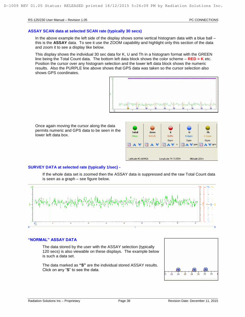
RS-125/230 User Manual – Revision 1.05 PC CONNECTIONS
Radiation Solutions Inc – Proprietary Page 38 Revision Date: December 11, 2015
ASSAY SCAN data at selected SCAN rate (typically 30 secs)
In the above example the left side of the display shows some vertical histogram data with a blue ball – this is the ASSAY data. To see it use the ZOOM capability and highlight only this section of the data and zoom it to see a display like below.
This display shows the individual 30 sec data for K, U and Th in a histogram format with the GREEN line being the Total Count data. The bottom left data block shows the color scheme – RED = K etc. Position the cursor over any histogram selection and the lower left data block shows the numeric results. Also the PURPLE line above shows that GPS data was taken so the cursor selection also shows GPS coordinates.
Once again moving the cursor along the data permits numeric and GPS data to be seen in the lower left data box.
SURVEY DATA at selected rate (typically 1/sec) -
If the whole data set is zoomed then the ASSAY data is suppressed and the raw Total Count data is seen as a graph – see figure below.
“NORMAL” ASSAY DATA
The data stored by the user with the ASSAY selection (typically 120 secs) is also viewable on these displays. The example below is such a data set.
The data marked as “S” are the individual stored ASSAY results.
Click on any “S” to see the data.
D-1009 REV 01.05 Status: RELEASED printed 18/12/2015 5:26:09 PM by Radiation Solutions Inc.

RS-125/230 User Manual – Revision 1.05 PC CONNECTIONS
Radiation Solutions Inc – Proprietary Page 39 Revision Date: December 11, 2015
SPECTRUM DISPLAY
Click on any of the spectral data (denoted by an “S”) and the full 1024 channel spectrum is seen. The cursor can be used to see Channel #, keV and cts for any channel in the spectrum. The spectrum can also be vertically scaled using the buttons and a LOG button permits easier viewing of higher energy low count rate events
This display has 5 tabs:
SPECTRUM – spectral display of the selected point
ASSAY – Assay data of the selected point
GPS – GPS data of the selected point
INFORMATION – gives additional data
CALIBRATION – gives the full cal matrix of the selected data point
Now this Comments ability is added, to insert data click the left pen icon (ADD – the one with a red mark is REMOVE). The position the cursor at the data point of interest and click it. Immediately data box will appear and the user can add comments (e.g. near Waterfall). Comments are seen as shown:
If the blue i is clicked, then users can enter info in the Comment field created above (e.g. test data) and this will appear next to the i button to permit users to label the data.
D-1009 REV 01.05 Status: RELEASED printed 18/12/2015 5:26:09 PM by Radiation Solutions Inc.

RS-125/230 User Manual – Revision 1.05 PC CONNECTIONS
Radiation Solutions Inc – Proprietary Page 40 Revision Date: December 11, 2015
4.6.2.1 DATA EXPORT
All recorded/displayed data can be output as txt files. Selects the EXPORT data process. The data box shows all Serial Numbers of data in the database – select as required.
User can select various data output:
SURVEY – retrieves the SURVEY scan data in a txt
file
ASSAY – retrieves the SURVEY scan data in a txt
file
SPECTRA – retrieves all stored spectra in full 1024
channel data format as a txt file
GPS TRACK – retrieves GPS data as a txt file
Most users should select ALL options just to be sure.
EXPORT FOLDER – user can select the sub
directory where the data is exported to
Select EXPORT – and all data files are transferred to the selected directories where they can be viewed as required (Excel Text data import etc.). The data is exported with embedded headers labeling data columns.
Typical export data into Excel Use Delimited by semi-colon to properly separate data columns, see examples below: a) ASSAY data
b) SURVEY
In the above example, the data have been exported from RSAnalyst and imported into Excel. Some columns have been deleted from the data set to make the figure above clearer.
ID Date Time Temperature Stabilized Total[ppm] Total[cpm] K[ppm] K[cpm] U[ppm] U[cpm] Th[ppm] Th[cpm] Dose Dose units Latitude Longitude Altitude
100 2/22/2008 14:56:33 22 1 33.7 283.8 0.15 17.3 0.8 7.6 2.69 5.2 13.49 nGy/h 43.636 -79.67861 192
101 2/22/2008 14:57:04 22.1 1 38.7 325.5 0.56 34 0 3.5 3.96 7.3 17.96 nGy/h 43.636268 -79.680163 198
102 2/22/2008 14:57:33 22.1 1 29.3 246.2 0.22 21.4 0.09 7.6 5.02 9.4 16.89 nGy/h 43.636425 -79.679847 203
103 2/22/2008 14:58:03 22.1 1 35.2 296.3 0.68 36 0 0 5.21 9.4 22.9 nGy/h 43.636427 -79.67984 200
104 2/22/2008 14:58:33 22.1 1 35.7 300.5 0.3 27.7 1.56 9.7 1.46 3.1 16.3 nGy/h 43.636423 -79.67984 201
105 2/22/2008 14:59:03 22.1 1 31.3 262.9 0.33 17.3 0 0 0.56 1 5.77 nGy/h 43.636418 -79.679832 193
106 2/22/2008 14:59:33 22.1 1 30 252.4 0.13 21.4 2.43 11.8 0.24 1 15.54 nGy/h 43.636413 -79.67982 191
107 2/22/2008 15:00:03 22.1 1 33.3 279.6 0.41 23.5 0.18 1.4 0 0 6.37 nGy/h 43.636403 -79.679815 191
108 2/22/2008 15:00:33 22.1 1 35.7 300.5 0.13 6.8 0 0 1.73 3.1 6.32 nGy/h 43.636398 -79.679812 191
109 2/22/2008 15:01:03 22.3 1 29 244.1 0.17 11 0 1.4 1.69 3.1 6.83 nGy/h 43.636393 -79.679808 195
110 2/22/2008 15:01:33 22.3 1 27.8 233.6 0.31 23.5 0.63 5.6 1.57 3.1 11.75 nGy/h 43.636393 -79.679808 196
111 2/22/2008 15:02:03 22.3 1 29.8 250.3 0.48 29.8 0.11 3.5 1.63 3.1 11.27 nGy/h 43.636397 -79.679808 192
112 2/22/2008 15:02:32 22.3 1 32 269.1 0 6.8 1.07 5.6 0.42 1 6.94 nGy/h 43.636398 -79.679808 192
Date Time Temp Smp rate s1 2 3 4 5 26 27 28 29 S30 Lat Long Alt
45 2/12/2008 15:36:12 19.2 30 1 35 44 46 41 40 41 44 47 45 34 43.622975 79.669925 190
46 2/12/2008 15:36:41 19.4 30 1 37 36 38 37 41 34 37 51 44 37 43.624885 79.672477 189
47 2/12/2008 15:37:11 19.4 30 1 38 44 38 46 35 36 25 33 42 39 43.626872 79.675147 191
48 2/12/2008 15:37:41 19.6 30 1 55 34 34 34 24 46 41 45 29 31 43.628152 79.677157 197
49 2/12/2008 15:38:11 19.8 30 1 34 36 37 42 40 28 36 37 45 41 43.627118 79.67879 192
50 2/12/2008 15:38:41 20 30 1 49 45 49 49 44 44 40 42 42 41 43.626533 79.67953 192
51 2/12/2008 15:39:11 20 30 1 33 39 49 49 39 65 47 51 63 56 43.626643 79.67979 193
52 2/12/2008 15:39:41 20.2 30 1 69 72 55 74 62 69 80 64 68 56 43.629507 79.681785 194
53 2/12/2008 15:40:11 20.2 30 1 69 57 50 58 61 51 70 53 64 73 43.632143 79.678108 198
54 2/12/2008 15:40:41 20.4 30 1 62 64 64 69 65 86 80 80 67 66 43.634382 79.672393 196
55 2/12/2008 15:41:11 20.4 30 1 69 69 57 71 70 64 61 72 68 72 43.636583 79.665713 193
D-1009 REV 01.05 Status: RELEASED printed 18/12/2015 5:26:09 PM by Radiation Solutions Inc.

RS-125/230 User Manual – Revision 1.05 PC CONNECTIONS
Radiation Solutions Inc – Proprietary Page 41 Revision Date: December 11, 2015
Note that the GPS location data shown after sample #30 is the position of Sample #1.
c) SPECTRA
The Assay data spectra file is stored in memory as an *.spc file and the example shows one such file imported into Excel. Data assignment as follows:
data 1 = LiveTime in mSec
data 2 = Clock Time (mSec) = (set time - # secs x
39mSec)
data 3 = spectral chn 1
data 1026 = spectral channel 1023 = Cosmic channel
data 1027 = Linearization coefficients
d) DATA-Serial#.kml This data file contains only the GPS coordinate data and is intended for direct import into
GOOGLE EARTH. Once imported the track position can be seen with Google’s GIS terrain overlays and is useful to confirm and inspect survey location.
4.6.3 MAPS Page
4.6.3.1 GENERAL
Map Layers requires an update to the RSAnalyst software rev – 0.147.2 or better. Selecting the Maps tab will open the following Page:
114725 LiveTime
114960 Clock Time
0 chn 1
1 chn 2
0 chn 3
0 ….
2 ….
0 ….
103 chn 1023
7.47 1.880176 2.970002 0.000140 chn 1024
D-1009 REV 01.05 Status: RELEASED printed 18/12/2015 5:26:09 PM by Radiation Solutions Inc.

RS-125/230 User Manual – Revision 1.05 PC CONNECTIONS
Radiation Solutions Inc – Proprietary Page 42 Revision Date: December 11, 2015
4.6.3.2 HOW TO USE MAPS:
Start RSAnalyst, collect and import data as usual. For this example a limited data set was collected in the vicinity of the RSI plant. The dataset is small but it is sufficient to explain functionality.
a) Select the MAPS Tab – the display will look similar to the example below.
b) Click SELECT DATA – and a data box appears (see example above) – Select the UNIAT and time period of interest, then select OK.
c) Select the Add button –
d) Select the RS-120x Tab and Counts if Total Count Recorded.
e) Click EDIT and then select one of the data lines by clicking on it. Adjust the Max/Min and Color to suit, then select UPDATE LIMIT to accept the changes.
f) Select RADIUS – the concept here is that the User should decide what radius of coverage has been achieved during the data traverses. Typically with a detector held 1m above the ground on traverse, then a maximum of 5m path is appropriate (but the User can experiment).
g) Press SET when entered.
D-1009 REV 01.05 Status: RELEASED printed 18/12/2015 5:26:09 PM by Radiation Solutions Inc.

RS-125/230 User Manual – Revision 1.05 PC CONNECTIONS
Radiation Solutions Inc – Proprietary Page 43 Revision Date: December 11, 2015
h) The data entry screen (located in the upper left) should look like this.
Various map layers can be added by pressing ADD again, selecting from the display then SET to add the layer.
Note that each layer has its own zoom limits (e.g. GOOGLE TERRAIN has much lower zoom than Google Maps) so the user needs to experiment to decide which layers they want. Once decided, select the non-required layer and select REMOVE to get eliminate them.
In the example only GOOGLE MAPS and GOOGLE EARTH are selected
i) Click AUTOZOOM to locate your dataset in the center of the screen and the max zoom level to display all the data. Data may look like this with no data showing:
D-1009 REV 01.05 Status: RELEASED printed 18/12/2015 5:26:09 PM by Radiation Solutions Inc.

RS-125/230 User Manual – Revision 1.05 PC CONNECTIONS
Radiation Solutions Inc – Proprietary Page 44 Revision Date: December 11, 2015
j) Use the UP/DOWN green arrows to cycle through the layers to display the data as required and use ZOOM (right hand slider or mouse wheel) as required – the test data set looks like this:
k) ASSAY – adding ASSAY data is a similar process and the map shows the ASSAY data collection points as blue flags.
l) Position the cursor on any of the flags and
the data from that location is displayed on the bottom left.
4.7 STATUS BAR
Connection Status Database Connection Device Time & Date
D-1009 REV 01.05 Status: RELEASED printed 18/12/2015 5:26:09 PM by Radiation Solutions Inc.

RS-125/230 User Manual – Revision 1.05 Rechargeable Battery SET
Radiation Solutions Inc – Proprietary Page 45 Revision Date: December 11, 2015
5.0 Rechargeable Battery SET
This set comprises 3 items:
- 4 x NiMH AA batteries (2500mA)
- 115V AC line adapter (or International 115/220V)
- Vehicle charging cable
PROCEDURE: a) Batteries - The user should mount the 4 batteries in the RS unit as described in Section 2.1.
For AC operation – connect the supplied line cord to the DC input connector of the RS unit (hidden under the waterproof tab on the bottom of the unit). The display shows this icon/message to show that charging is taking place:
Once connected to the AC line the unit should take typically 4 HOURS (at 20
0 C) to reach full charge –
longer at colder temperatures. Leaving the unit connected to the AC line overnight is OK but don’t leave it connected for an indefinite period (more than 24 hrs) or potential battery damage could occur.
If the icon labeled POWER SUPPLY appears this means that the wrong
batteries are selected. Power off the unit, remove and replug in the battery holder then on power on, select RECHARGEABLE batteries.
NOTE: The batteries supplied with the RS-125 unit are NiMH rechargeable
batteries. It is best to “condition” these batteries when first used to ensure a good battery life. The ideal form of conditioning is:
- fully charge the batteries in the unit – minimum of 4 hours
- completely discharge the unit – 10 hours
- fully charge the batteries a second time – minimum of 4 hours
- completely discharge the unit a second time – 10 hours
- fully charge the batteries a third time – minimum of 4 hours
- completely discharge the unit a third time– 10 hours
Now the batteries should give their optimum life. Try to ensure at least 2 charge/discharge cycles. c) DC operation - If an AC source is not available the supplied VEHICLE charging cable can be used -
this requires access to a 12V (max 20V) battery. Connect the supplied Vehicle Charging Cable to the DC input connector of the RS unit (hidden under the waterproof tab on the bottom of the unit). Connect the Cigarette lighter plug on the cable to the appropriate Vehicle connection – RS display should show the “CHARGING” message as noted above. Typical charge is 4 HOURS (at 20
0 C) to
reach full charge – longer at colder temperatures. NB Ensure that the Vehicle connection is powered on (red LED on the connector) as some units power OFF when the ignition key is switched off (check that the unit is displaying the “CHARGING” label as shown above even when ignition is OFF)..
NOTE: Starting a vehicle can cause many bad voltage transients on the power line that can damage
sensitive electronic equipment. For this reason users are advised to unplug the charger during vehicle starting.
POWER SUPPLY
CHARGING
D-1009 REV 01.05 Status: RELEASED printed 18/12/2015 5:26:09 PM by Radiation Solutions Inc.

RS-125/230 User Manual – Revision 1.05 Rechargeable Battery SET
Radiation Solutions Inc – Proprietary Page 46 Revision Date: December 11, 2015
This Page is intentionally left Blank.
D-1009 REV 01.05 Status: RELEASED printed 18/12/2015 5:26:09 PM by Radiation Solutions Inc.

RS-125/230 User Manual – Revision 1.05 Appendix A - ASSAY ANALYSIS
Radiation Solutions Inc – Proprietary Page 47 Revision Date: December 11, 2015
Appendix A - ASSAY ANALYSIS
Comments re Precision:
General
The RS-125 Portable Gamma Spectrometer units have an integrated 6.3 cu ins Sodium-Iodide detector for Gamma Ray detection. This very large sensor coupled with the 1024 channel spectrometer capability of the unit permit high levels of sensitivity for Geophysical prospecting. However like all instruments, measurement accuracy is dependent on a variety of factors. This note briefly explains the basic errors related to instrument measurement and computes approximate system Precision capabilities.
There are various primary sources of error. a) STATISTICAL – if we assume the calibration parameters are 100% correct then the accuracy of a
reading is strictly related to the statistical noise of the counting, so if we count long enough we can reach any degree of precision and accuracy.
b) CALIBRATION - there are some level of errors when the unit is calibrated, so the measured calibration
matrix is offset relative to the correct matrix. This will result in a systematic small error component that effects the accuracy. For levels below approximately the pad concentrations of 8% K, 50ppm U, and 140ppm Th – with an Assay Time of 2 min, this systematic error is small compared to the statistical error and can be ignored. At higher levels or if the counting time is extended (4 minutes at 4%K, 25 ppm U, 70 ppm Th) this error will get comparable to the statistical error and keep increasing faster than the statistical error.
c) GEOMETRY - the other factor that should be considered is the geometry. The assumption in
computing the assay results inside the unit is that the detector is looking at a semi-infinite half space of uniform material. In more practical terms this means the instrument is averaging a circular area approximately 3 feet diameter. Thus if the rocks inside this 3ft zone are fully homogenous, then the Assay results from the instrument will approximate that of Chemical assay – however in the field this assumption is difficult to ensure so in most cases the Assay are an excellent INDICATION of the level of actual chemical assay results.
d) COUNTING TIME – the length of the sample (Assay) time is a function of the users requirements. In
the past, 300 secs (5 mins) was used as the standard to suit all field conditions as this gave good results in even low level areas. However much exploration now takes place in relatively high grade areas where this long assay period is not necessary and for many users this 5 min period was considered excessive. For this reason the RS-125 is factory set at 120 secs (but changeable by the user to suit their field requirements). When the sample starts, a preset Sample Time parameter shows the sample time on the right and on the left is a count up timer showing sample progress. Once the first 30 secs sample is reached an Assay result is shown. Each additional 30 secs the Assay data is recomputed and updated on the display.
For best accuracy the full count period should be permitted. However in very anomalous areas sample times as low as 60 seconds give very good data due to the large detector size.
D-1009 REV 01.05 Status: RELEASED printed 18/12/2015 5:26:09 PM by Radiation Solutions Inc.

RS-125/230 User Manual – Revision 1.05 Appendix A - ASSAY ANALYSIS
Radiation Solutions Inc – Proprietary Page 48 Revision Date: December 11, 2015
Guidelines are:
60 secs – anomalous area – low quality data is fine – fast sampling is required to get maximum data for an area in a short period of time.
120 secs – anomalous area – medium quality data is fine – fast sampling is required to get maximum data for an area in a short period of time
180 secs – medium anomalous area – good quality data is required
240 secs – medium to low anomalous area – high quality data is required
300 secs – low anomalous area – maximum quality data is required
IN THE ANALYSIS BELOW 120 secs ASSAY PERIOD IS ASSUMED
The table below shows the estimated error bars at the 1 Sigma level, so +/- 1 sigma is a good estimate of data precision but only errors (a) are included in this assessment.
a) RS-125 DATA
NOTE: The above data have been computed taking into account the errors described. However as described above the final absolute precision levels are a factor of many of the errors described, some of which are hard to quantify for the reasons noted. For this reason the quoted error levels should be used in a relative rather than an absolute manner to ensure technical accuracy.
ZERO RESULTS
Under certain conditions some Assay results go to zero. This is caused by statistical noise errors interfering with the matrix calculation of Assay computation. Using the statistical noise calculations above, as an example if you have a 120 sec sample and a 100ppm Thorium sample with 10ppm Uranium, then the assy result for +/-1SD will be Th=100+/-5.5ppm and U=10+/- 3.3ppm thus in some samples U could = 0.00. This “noise” error can be minimized by taking very long Assay samples which reduces the scatter.
K % 1 sigma K% 1 sigma U ppm 1 sigma Th ppm
0 0.000 0.000 0.000
0.1 0.030 0.041 0.006
1 0.096 0.130 0.019
5 0.214 0.291 0.042
10 0.303 0.412 0.060
U ppm 1 sigma K% 1 sigma U ppm 1 sigma Th ppm
0 0.000 0.000 0.000
1 0.043 0.307 0.027
10 0.135 0.970 0.087
100 0.427 3.067 0.274
1000 1.349 9.698 0.866
10,000 4.27 30.67 2.74
Th ppm 1 sigma K% 1 sigma U ppm 1 sigma Th ppm
0 0.000 0.000 0.000
1 0.023 0.237 0.539
10 0.072 0.750 1.705
100 0.228 2.373 5.391
1000 0.721 7.504 17.047
10,000 2.28 23.7 53.9
D-1009 REV 01.05 Status: RELEASED printed 18/12/2015 5:26:09 PM by Radiation Solutions Inc.

RS-125/230 User Manual – Revision 1.05 Appendix A - ASSAY ANALYSIS
Radiation Solutions Inc – Proprietary Page 49 Revision Date: December 11, 2015
CROSS INTERFERENCE - for varying concentrations of e.g. Potassium there are error components for not only K but also U, Th etc. If you have a mix of K, U, Th - the combined errors can be found by taking the square root of the sum of the square of errors. If for example you have 1% K, 10 ppm U, and 10 ppm Th the combined K error is SQRT(0.096*0.096 + 0.135*0.135 + 0.072+0.072) = 0.18. b) RS-230 DATA
The RS-230 data is approximately 2x better than the RS-125 data noted above due to the BGO detector technology. REFERENCE
The above data is based on Calibration data derived from RSI Calibration Pads. These pads are technically defined in the 1991 Geological Survey of Canada paper #90-23 titled “Transportable Calibration Pads for Ground and Airborne Gamma-Ray Spectrometers” by Grasty, Holman and Blanchard. This paper fully describes the manufacture and the assay testing of the material to verify the pad calibration results. Window widths of ROIs and cal standards were defined to IAEA standards as required.
D-1009 REV 01.05 Status: RELEASED printed 18/12/2015 5:26:09 PM by Radiation Solutions Inc.

RS-125/230 User Manual – Revision 1.05 Appendix A - ASSAY ANALYSIS
Radiation Solutions Inc – Proprietary Page 50 Revision Date: December 11, 2015
This Page is intentionally left Blank.
D-1009 REV 01.05 Status: RELEASED printed 18/12/2015 5:26:09 PM by Radiation Solutions Inc.

RS-125/230 User Manual – Revision 1.05 Appendix B - Fast GPS Sampling on Total Count Data
Radiation Solutions Inc – Proprietary Page 51 Revision Date: December 11, 2015
Appendix B - Fast GPS Sampling on Total Count Data
Some users want to record GPS data at a faster rate when recording Total Count data. Firmware Versions including and after v5.19 permits this but there are some compromises. In the normal software, Total Count scan data is recorded in data blocks of 30 samples, after which GPS is recorded. This memory block size is not practical to change however users can adapt the scan rate to get faster GPS data. To do this, users should load a special parameter file named “GPSfastscan.txt” that should be supplied with the new software but can be obtained from RSI as required.
This txt file looks like this:
Params.survey_rec_len = 30
Change the number as required for example to 15, then store the file (only use Notepad or WordPad – don’t use WORD as it adds formatting characters that will cause file loading problems) Then load the file into the unit using the method detailed in Section 4.5.5.1 under PARAMETER CHANGE. In the above example if Total Scan Period = 1 and the above file sets “Survey_rec_len” = 15 – then when RECORDING is started, the Total Count data is recorded at a 1/sec rate for 15 samples then the GPS is recorded and the recording repeated.
NOTE: In this case the allotted memory determined during memory partitioning is actually half of what is indicated because memory is allocated for 30 samples of data and only 15 are being recorded. However the new units with 4MB of memory have 58 sectors for allocation, (see Section 4.5.5.3 for more information) so memory capacity should not be a problem.
D-1009 REV 01.05 Status: RELEASED printed 18/12/2015 5:26:09 PM by Radiation Solutions Inc.

RS-125/230 User Manual – Revision 1.05 Appendix B - Fast GPS Sampling on Total Count Data
Radiation Solutions Inc – Proprietary Page 52 Revision Date: December 11, 2015
This Page is intentionally left Blank.
D-1009 REV 01.05 Status: RELEASED printed 18/12/2015 5:26:09 PM by Radiation Solutions Inc.

RS-125/230 User Manual – Revision 1.05 Appendix C – RS-230 System Stabilization and Data Reliability
Radiation Solutions Inc – Proprietary Page 53 Revision Date: December 11, 2015
Appendix C – RS-230 System Stabilization and Data Reliability
C.1 GENERAL
This technical note is intended as a guide for users of the RS-230 and provides details concerning auto stabilization and data reliability.
C.2 STABILIZATION
In the early versions of the RS-230 firmware (software inside the unit), under certain conditions some units had intermittent problems stabilizing. RSI carried out extensive experimentation and with various improvements in the analysis system, the current version of firmware (5v95) is very reliable and robust.
However if the user has concerns with stabilization the following are the steps they should take with RSI to resolve these problems:
a) UPGRADE F/W to 5v95 – this version seems very robust so the first step is to power the unit on and see what version is currently used by the unit. If it is not 5v95, then contact RSI to receive the 5v95.gfw file that is loaded into the unit via RSAnalyst.
b) LOAD CORRECT PARAMETERS – RSI can supply users with a set of recommended parameters which are then loaded into the unit via RSAnalyst. These parameters are optimized for the RS-230 and contain special settings which have shown to be optimum under most conditions.
c) STABILIZATION TEST – with both (C.2.a) and (C.2.b) above accomplished, it is recommended that the user plug a battery charger into the unit and let it run in the SURVEY mode for at least 4 hours but preferably longer. To simplify issues, RSI recommends that after the Stabilization Test; that users download the Stabilization File using RSAnalyst and email it to RSI-Service at [email protected] for proper assessment (see Appendix Z).
d) ADJUSTED PARAMETERS – under some circumstances, after assessing the data RSI may send a new set of Parameters to tweak the systems performance. In this case we will ask you to repeat step (C.2.c) to be sure all is now OK.
This procedure usually resolves most of the issues; if not, the system probably has a hardware problem and needs to be returned to factory for service.
Contact RSI-Service at [email protected].
C.3 DATA RELIABILITY
Some users have carried out repeatability experiments and sent the data to RSI to review/address the repeatability results.
In many situations the data scatter is due to the unit not being properly stabilized. The procedures noted above in (C.2) should resolve this. However if stabilization is OK, very significant errors can easily occur during data experiments by changing geometry between the detector and the source used for the test. In most cases users would utilize a somewhat radioactive rock. The main problem here is that such sources act like point sources and small geometry changes cause significant data errors. When the raw data (of concern) is sent to RSI, it is impossible for us to comment as we have no knowledgeable of how the experiments were performed.
D-1009 REV 01.05 Status: RELEASED printed 18/12/2015 5:26:09 PM by Radiation Solutions Inc.

RS-125/230 User Manual – Revision 1.05 Appendix C – RS-230 System Stabilization and Data Reliability
Radiation Solutions Inc – Proprietary Page 54 Revision Date: December 11, 2015
NOTE: In the following tests the GR-320 (by Exploranium, now obsolete) was once the “standard”, is
used as a baseline in comparison to the RSI RS-230 unit.
a) “SOURCE”
To minimize the Geometry issues, RSI utilized our 1m x 1m concrete test pads that contain small amounts of K, U and Th. The advantage here is that the pads are homogeneous over the 1m x 1m area thus small geometry changes will have little effect.
The picture shows the experiment with 2 x RS-230 and 2 x GR-320 making simultaneous measurements.
b) TEST PROTOCOL
To keep the experiment as close as possible to field work, RSI set all units for a “standard” 120 second sample time.
All units were run for at least 4 hours prior to the measurements to ensure system stabilization was OK.
The RS-230 units continue to stabilize on or off the pad, whereas the GR-320 stabilization must be switched off. To minimize this operational limitation of the GR-320, after each data set the units were all run on the K pad with stabilization enabled so the GR-320 could fine tune itself before the next data set.
Data was taken on each of the Potassium, Uranium and Thorium pads with 10 x 2 minute samples for each unit.
c) RESULTS
The table shows the data on the Uranium and Thorium pads. 320.1832 = GR-320 serial #1832 and 230/3373 is RS-230 serial #3373 etc.
The Uranium pad is nominally 52.9 ppm - the Thorium pad is nominally 136 ppm
Normally we use an 85% geometry correction factor as even the 1m x 1m test pads are not infinite size but for this experiment we used 80% as the detectors were offset.
So after correction the data should show the Uranium = 42.3 ppm and Thorium = 108.8 ppm
230/320 testing - on pads ppm
U pad 120secs Th pad 120secs
320/1832 320/2017 230/3373 230/3375 320/1832 320/2017 230/3373 230/3375
47.6 45.6 41.8 42.9 116.4 112.3 101.1 105.0
45.2 45.2 44.8 41.5 119.4 123.1 110.3 104.2
48.3 45.3 43.6 42.2 119.9 115.8 100.5 104.6
45.0 41.6 42.3 42.3 123.1 122.9 107.0 106.6
45.8 46.5 43.3 40.3 122.7 117.1 101.6 106.6
47.3 46.9 42.3 44.3 117.0 117.9 109.3 105.6
44.8 45.4 42.8 42.8 119.8 114.8 105.1 106.7
45.0 48.4 40.5 44.1 121.9 118.6 108.8 107.1
46.2 44.0 43.7 43.0 121.0 112.4 110.9 104.9
47.3 45.3 41.5 42.1 122.3 117.0 105.8 101.8
Average ppm 46.3 45.4 42.7 42.6 120.3 117.2 106.0 105.3
SD 1.3 1.8 1.2 1.2 2.3 3.7 3.9 1.6
Average SD
Max ppm 48.3 48.4 44.8 44.3 123.1 123.1 110.9 107.1
Min ppm 44.8 41.6 40.5 40.3 116.4 112.3 100.5 101.8
Max SD 1.6 1.7 1.7 1.5 1.2 1.6 1.2 1.1
Min SD 1.1 2.1 1.7 1.9 1.7 1.3 1.4 2.2
1.3 1.2 3.0 2.7
D-1009 REV 01.05 Status: RELEASED printed 18/12/2015 5:26:09 PM by Radiation Solutions Inc.

RS-125/230 User Manual – Revision 1.05 Appendix C – RS-230 System Stabilization and Data Reliability
Radiation Solutions Inc – Proprietary Page 55 Revision Date: December 11, 2015
This data clearly shows identical repeatability between the computed Assay data from the RS-230 and the GR-320, as well as excellent data repeatability for both. The GR-320 data is slightly higher on the U and Th side but within normal statistical range.
The next table shows the same data but using the stripped counts/time period rather than the ppm.
SUMMARY
RS-230 Stabilization issues can be easily resolved using the procedures noted above (see Section C.2).
NOTE: The RS-230 shows excellent repeatability of the data and the data shows that it is essentially equivalent in performance and data reliability to the GR-320 system often referred to as the “standard”. The GR-320 uses a 21 cubic inch NaI crystal whereas the RS-230 uses a 6.3 cubic inch crystal. The GR-320 is now obsolete and no longer available.
230/320 testing - on pads cps
U pad 120secs Th pad 120secs
320/1832 320/2017 230/3373 230/3375 320/1832 320/2017 230/3373 230/3375
1,741 1,826 1471.6 1511.4 1,780 1,772 1757 1824.4
1,652 1,812 1575.4 1467.2 1,826 1,940 1912.6 1809.8
1,777 1,823 1534 1484.4 1,831 1,829 1745.8 1815.2
1,664 1,686 1491.2 1487.4 1,881 1,933 1858.8 1850.0
1,681 1,887 1523 1432.6 1,876 1,849 1764 1851.8
1,727 1,868 1487.2 1551.6 1,794 1,863 1896.6 1836.2
1,651 1,816 1507.8 1511.6 1,830 1,811 1825 1860.4
1,653 1,931 1435.2 1550.8 1,863 1,872 1890.6 1823.4
1,686 1,767 1537.4 1510.8 1,849 1,777 1925 1769.0
1,730 1,825 1459.8 1482.0 1,865 1,849 1837.6 1830.2
Average 1696.3 1824.2 1502.3 1499.0 1839.4 1849.7 1841.3 1827.0
Theory sigma 44.6 66.5 41.7 36.5 33.9 56.8 67.0 26.2
Actual Sigma 41.2 42.7 38.8 38.7 42.9 43.0 42.9 42.7
Real Sigma 17.0 51.0 15.4 13.0 26.3 37.1 51.4 33.8
Variation (%) 1.0 2.8 1.0 0.9 1.4 2.0 2.8 1.8
D-1009 REV 01.05 Status: RELEASED printed 18/12/2015 5:26:09 PM by Radiation Solutions Inc.

RS-125/230 User Manual – Revision 1.05 Appendix C – RS-230 System Stabilization and Data Reliability
Radiation Solutions Inc – Proprietary Page 56 Revision Date: December 11, 2015
This Page is intentionally left Blank.
D-1009 REV 01.05 Status: RELEASED printed 18/12/2015 5:26:09 PM by Radiation Solutions Inc.

RS-125/230 User Manual – Revision 1.05 Appendix D Calibration of the RS-125 and/or RS-230
Radiation Solutions Inc – Proprietary Page 57 Revision Date: December 11, 2015
Appendix D Calibration of the RS-125 and/or RS-230
NOTE: To be performed on User Accessible Test Pads.
D.1 GENERAL:
The RS-125 and RS-230 units supplied by RSI have been calibrated on specially designed Test Pads. Dr. R.L. Grasty et al made a series of test pads for calibration and they are distributed around the world. In addition some specialty users have constructed their own pads.
Many users want to re-calibrate their instruments 1/year and if they reside outside of Canada it imposes a significant cost burden to send the units back to RSI for calibration.
This procedure explains the process the user must follow to use local test pads to calibrate their unit.
D.2 REQUIRED ITEMS
1 Detailed technical information about the Test Pads being used
2 RS-Analyst version 0.110 or higher + Pad Calibration plug in (contact RSI if required).
D.3 LOAD CALIBRATION FILE
Obtain the technical information about the pads and enter the following data:
a) Unzip patch file (rs125calib.zip) and move extracted rs125calib.dll file to the RS-Analyst installation directory :\.........\RS-Analyst\plugins\rs125calib.dll
b) Start RS-Analyst and verify that version level is 0.110 or higher.
c) Verify that the Calibration plug in is installed – icon as shown here .
d) Connect the unit to RS-Analyst by (Blue-tooth) BT or USB as normal.
e) Click the icon and select Add from the
next display.
f) Enter a pad name (e.g. RSI test pad) then enter data in the table:
Q 00: K pad data for K
Q 01: K pad data for U
Q 02: K pad data for Th
Q 10: U pad data for K
Q 11: U pad data for U
D-1009 REV 01.05 Status: RELEASED printed 18/12/2015 5:26:09 PM by Radiation Solutions Inc.

RS-125/230 User Manual – Revision 1.05 Appendix D Calibration of the RS-125 and/or RS-230
Radiation Solutions Inc – Proprietary Page 58 Revision Date: December 11, 2015
Q 12: U pad data for Th
Q 20: Th pad data for K
Q 21: Th pad data for K
Q 22: Th pad data for K
Q 30: Blank pad data for K
Q 31: Blank pad data for K
Q 32: Blank pad data for K
Q 40: 0
Q 41: 0
Q 42: 0
COR 0: K pad geometric correction (e.g. 0.857 = 85.7%)
COR 1: U pad geometric correction (e.g. 0.857 = 85.7%)
COR 2: Th pad geometric correction (e.g. 0.857 = 85.7%)
COR 3: 1
COR 4: 1
g) Select Create profile
h) Click on Save to file and store the file for future use: example name = Oz’s test pad
i) Next select Save to device to load the data into the unit, if all is OK a message should display; “Master Parameters were successfully updated”.
j) The pad calibration file is now permanently loaded into the unit and will remain there until new pad data is loaded.
D.4 ENABLE CALIBRATION MODE
Loading the Calibration Parameters:
Find the file “Enable Calibration Mode.txt” which was sent with the calibpatch.zip package.
With the unit still connected to RS-Analyst, select Device Parameters.
Select the Device Settings tab.
Select the Load Parameters from file button.
Browse to select the Enable Calibration Mode.txt file and click Open.
A message is displayed “Are you sure you want to rewrite parameters” – say YES.
A “Success” button is displayed – click OK.
The unit is now capable of Pad Calibration using the pad data previously installed.
D-1009 REV 01.05 Status: RELEASED printed 18/12/2015 5:26:09 PM by Radiation Solutions Inc.

RS-125/230 User Manual – Revision 1.05 Appendix D Calibration of the RS-125 and/or RS-230
Radiation Solutions Inc – Proprietary Page 59 Revision Date: December 11, 2015
D.5 CALIBRATE UNIT
a) Ensure the unit has fully charged batteries.
b) Run the unit on the desk for at least 1 hour to ensure it is fully stabilized.
c) Go to the vicinity of the Test pads and on the unit select Configuration Calibration Pads calib.
d) Then select Default device BG. Display shows “Using default device background”, click the Button to go back to the menu.
e) Then Place the unit upside down in the middle of the pad so the battery compartment is facing up/ rubber top is touching the pad. Now select K pad, after 300secs the unit will beep and the display will show K saved.
f) Repeat this process for the Uranium pad but this time select U pad.
g) Repeat this process for the Thorium pad but this time select Th pad.
h) Repeat this process for the Background pad but this time select Bg pad. Note that the Bg pad measurement will take 600sec.
i) Then select Calculate matrix – and after a few seconds the display will show “Matrix calculated”.
j) Select Go back.
k) Select disable calibration mode.
l) Return to the survey mode screen.
m) Test the unit.
D-1009 REV 01.05 Status: RELEASED printed 18/12/2015 5:26:09 PM by Radiation Solutions Inc.

RS-125/230 User Manual – Revision 1.05 Appendix D Calibration of the RS-125 and/or RS-230
Radiation Solutions Inc – Proprietary Page 60 Revision Date: December 11, 2015
This Page is intentionally left Blank.
D-1009 REV 01.05 Status: RELEASED printed 18/12/2015 5:26:09 PM by Radiation Solutions Inc.

RS-125/230 User Manual – Revision 1.05 Appendix Z WARRANTY
Radiation Solutions Inc – Proprietary Page 61 Revision Date: December 11, 2015
Appendix Z WARRANTY
Radiation Solutions Inc Warranty
RS-125 (Super-Spec) and RS-230 (BGO Super-Spec) series products are provided with a one (1) year return to factory limited warranty against defects in materials and workmanship from the date the Products are placed at the disposal of the Buyer at the named place of delivery. The warranty does not cover damage caused by improper use or unauthorized repairs.
Repairs of defects will be performed by RSI at no charge to the Buyer, subject to the limitations. To request warranty service, the Buyer must call RSI’s service coordinator for a return material authorization (RMA) number.
The Buyer is responsible for all the shipping, customs clearance costs and risk of loss of returning the repaired or replaced Products to the Buyer. RSI will own all parts removed from repaired Products or all Products replaced.
RSI’s warranty does not include breakage of the crystal for any reason. RSI does warrant the detectors to be complete and fully operational to their published specifications at the time of delivery and to maintain the minimum resolution and performance for a period of one year under normal operating condition.
Complete details of the “Standard Terms and Conditions” may be obtained by contacting RSI. For more information or to make a warranty claim contact RSI.
Contact Information Phone: (905) 890-1111 Fax: (905) 890-1964 Email: [email protected] [email protected]
D-1009 REV 01.05 Status: RELEASED printed 18/12/2015 5:26:09 PM by Radiation Solutions Inc.


![1.05 Mb [Download]](https://img.pdfslide.us/doc/110x75/587f2c131a28abb43f8bc435/105-mb-download.jpg)