Embed Size (px)
Citation preview
TRANSPORT AND ROAD RESEARCH LABORATORY Department of Transport R R L
Contractor Report 228
Bur ied f lexible pipes: 1 Design methods present ly used in Br i ta in
by G N Smith and O C Young. Consultants
The work reported herein was carried out under a contract placed on G N Smith and O C Young Consultants by the Transport and Road Research Laboratory. The research customer for this work is Highways Engineering Division, DTp.
This report, like others in the series, is reproduced with the authors' own text and illustrations. No attempt has been made to prepare a standardised format or style of presentation.
Copyright Controller of HMSO 1991. The views expressed in this Report are not necessarily those of the Department of Transport. Extracts from the text may be reproduced, except for commercial purposes, provided the source is acknowledged.
Ground Engineering Division Structures Group Transport and Road Research Laboratory Old Wokingham Road Crowthorne, Berkshire RG11 6AU
1991
ISSN 0266-7045
Ownership of the Transport Research Laboratory was transferred from the Department of Transport to a subsidiary of the Transport Research Foundation on 1 st April 1996.
This report has been reproduced by permission of the Controller of HMSO. Extracts from the text may be reproduced, except for .commercial purposes; provided the source-is acknowledged:
CONTENTS
i. Introduction
Page
1
2. Buried pipes - basic design approaches
2.1 Rigid pipes 2.2 Flexible pipes 2.3 Deflection time lag factor 2.4 Buckling of a circular pipe 2.5 Ring compression theory
3. The CIRIA design procedure for buried flexible pipes
3.1 Required data 3.2 External loads on pipes 3.3 Maximum D/t ratio 3.4 Pipe specific stiffness 3.5 Critical buckling pressure 3.6 Deflection calculations 3.7 Minimum pipe stiffness for handling stresses
2 4
13 13 16
18
18 19 22 23 23 24 26
4. The Water Research Centre design procedure for buried flexible pipes
4.1 Backfillmaterial selection 4.2 Pipe deflections 4.3 Buckling
2
33 35 36
5. Comments on design methods presently used in Britain
6. Acknowledgements
7. References
Appendix I
Appendix II
Appendix III
Example 1
Example 2
Example 3 (Spangler's approach)
Example 4 (Barnard's approach)
Example 5 (W.R.C.'s approach)
Figures
39
39
40
43
44
50
45
46
26
28
37
51
i
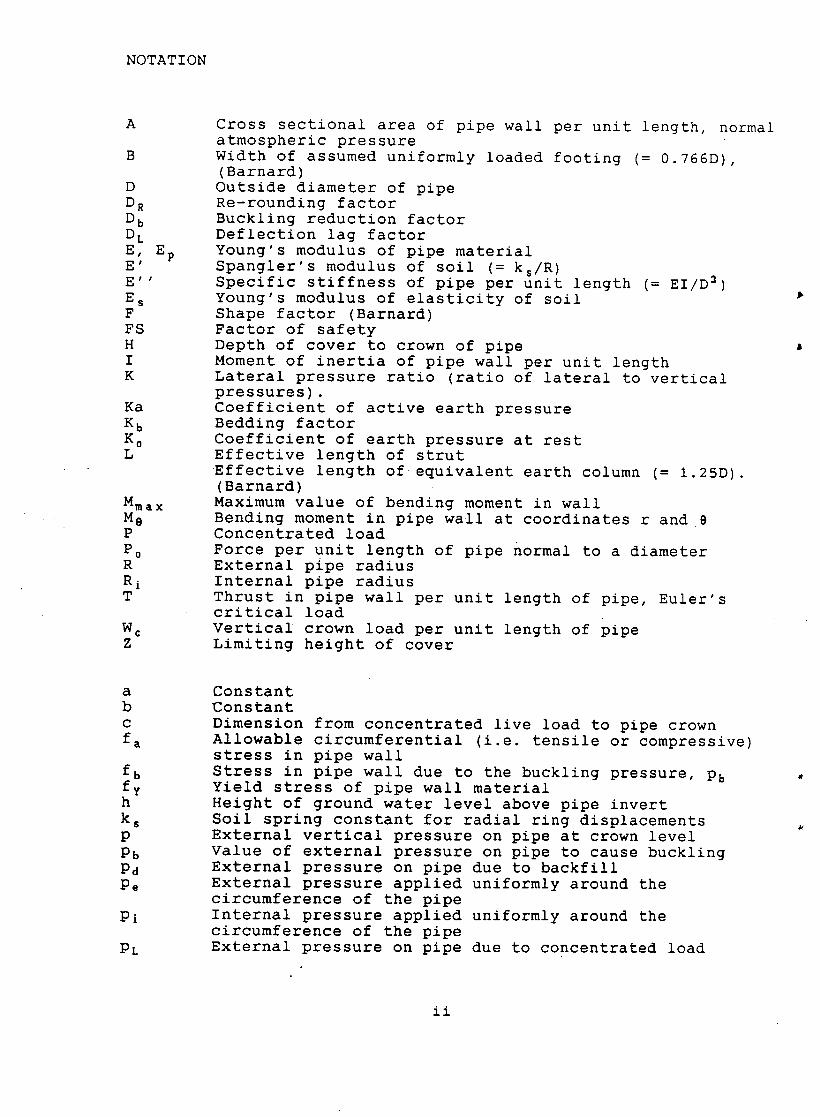
NOTATION
A
B
D DR Db DL E, Ep E' E ' ' Es F F S H I K
Ka Kb Ko L
Mmax Me P P0 R Ri T
We Z
Cross sectional area of pipe wall per unit length, normal atmospheric pressure Width of assumed uniformly loaded footing (= 0.766D), (Barnard) Outside diameter of pipe Re-rounding factor Buckling reduction factor Deflection lag factor Young's modulus of pipe material Spangler's modulus of soil (= ks/R ) Specific stiffness of pipe per unit length (= EI/D s) Young's modulus of elasticity of soil Shape factor (Barnard) Factor of safety Depth of cover to crown of pipe Moment of inertia of pipe wall per unit length Lateral pressure ratio (ratio of lateral to vertical pressures). Coefficient of active earth pressure Bedding factor Coefficient of earth pressure at rest Effective length of strut • Effective length of•equivalent earth column (= 1.25D). (Barnard) Maximum value of bending moment in wall Bending moment in pipe wall at coordinates r and 8 Concentrated load Force per unit length of pipe normal to a diameter External pipe radius Internal pipe radius Thrust in pipe wall per unit length of pipe, Euler's critical load Vertical crown load per unit length of pipe Limiting height of cover
a b c fa
fb fy h ks P Pb Pd Pe
Pi
PL
Constant Constant Dimension from concentrated live load to pipe crown Allowable circumferential (i.e. tensile or compressive) stress in pipe wall Stress in pipe wall due to the buckling pressure, Pb Yield stress of pipe wall material Height of ground water level above pipe invert Soil spring constant for radial ring displacements External vertical pressure on pipe at crown level Value of external pressure on pipe to cause buckling External pressure on pipe due to backfill External pressure applied uniformly around the circumference of the pipe Internal pressure applied uniformly around the circumference of the pipe External pressure on pipe due to concentrated load
ii
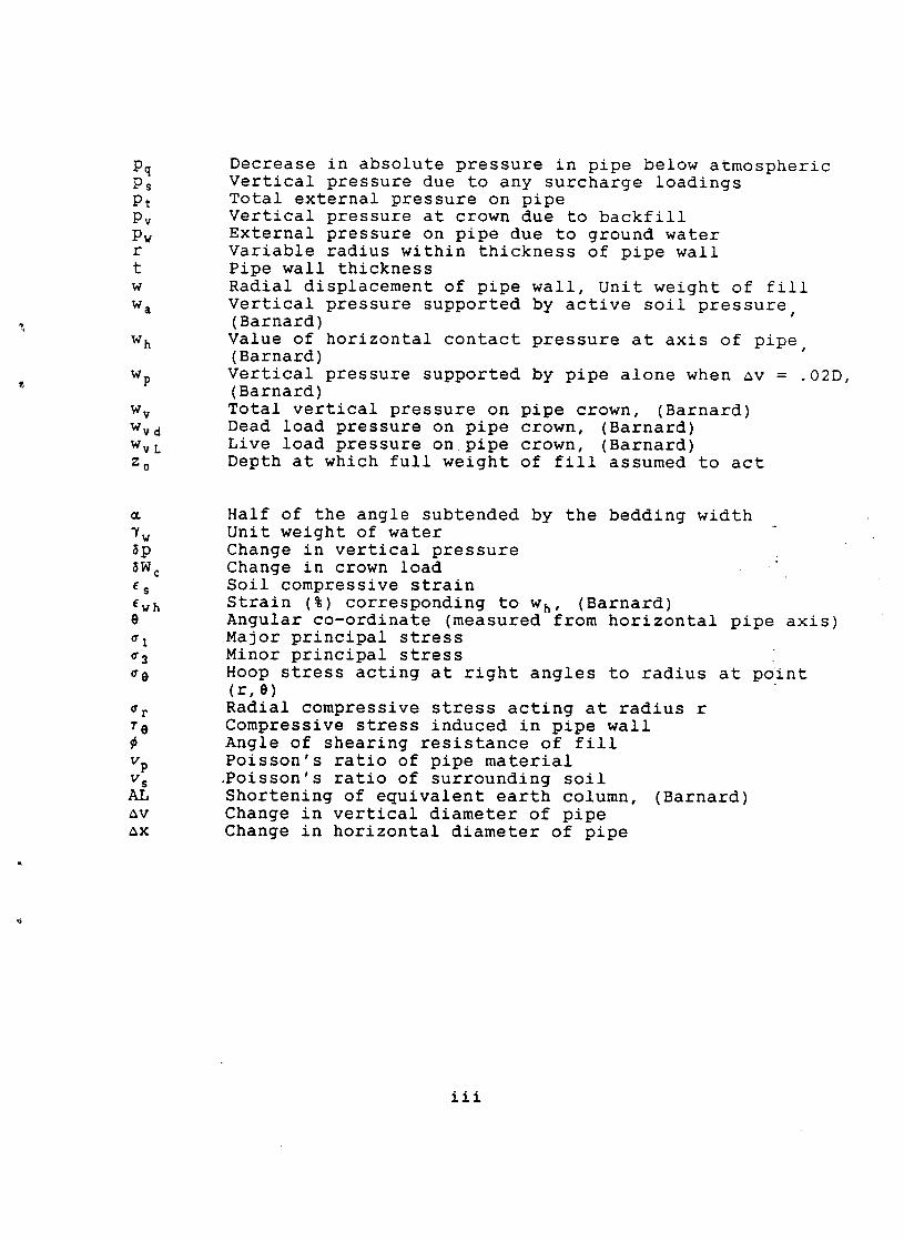
Pq Ps Pt Pv Pw r t w w a
W h
Wp
w V Wvd WvL Z 0
Decrease in absolute pressure in pipe below atmospheric Vertical pressure due to any surcharge loadings Total external pressure on pipe Vertical pressure at crown due to backfill External pressure on pipe due to ground water Variable radius within thickness of pipe wall Pipe wall thickness Radial displacement of pipe wall, Unit weight of fill Vertical pressure supported by active soil pressure, (Barnard) Value of horizontal contact pressure at axis of pipe (Barnard) Vertical pressure supported by pipe alone when av = .02D, (Barnard) Total vertical pressure on pipe crown, (Barnard) Dead load pressure on pipe crown, (Barnard) Live load pressure on pipe crown, (Barnard) Depth at which full weight of fill assumed to act
G&
7w ~p
~W c ~s Ewh e
¢3 ~0
~r 70
vp v s AL av ax
Half of the angle subtended by the bedding width Unit weight of water Change in vertical pressure Change in crown load Soil compressive strain Strain (%) corresponding to Wh, (Barnard) Angular co-ordinate (measured from horizontal pipe axis) Major principal stress Minor principal stress Hoop stress acting at right angles to radius at point (r,0) Radial compressive stress acting at radius r Compressive stress induced in pipe wall Angle of shearing resistance of fill Poisson's ratio of pipe material .Poisson's ratio of surrounding soil Shortening of equivalent earth column, (Barnard) Change in vertical diameter of pipe Change in horizontal diameter of pipe
iii
BURIED FLEXIBLE PIPES
DESIGN METHODS PRESENTLY USED IN BRITAIN
1 INTRODUCTION
The present methods most widely used for the design of buried
flexible pipes have been reviewed in two publications, one by the
American Highway Research Board, Progress Report No. 116,
prepared by Krizek et al. (1971) and the other by the Construction
Industry Research and Information Association (CIRIA), Report
No.78, prepared by Compston et al. (1978).
It has long been felt that these methods have a common shortcoming
in that they all consider the various criteria used for the
structural performance of the pipe separatelY so that, with each
criterion based on a different set of assumptions, the designer
cannot readily assess which one is the most critical for his
design.
In 1977 the Transport and Road Research Laboratory (TRRL)
commissioned Mott, Hay and Anderson, Consulting Engineers, to
examine this unsatisfactory situation and to attempt to develop a
more rational approach to the design of buried flexible pipes.
The work, backed up by both research, model and prototype tests,
has now been completed and limited details of this new design
method, which provides a unified approach to the prediction of
values of deflection, stresses and buckling, have been published
(Gumbel & Wilson, 1981; Gumbel, O'Reilly, Lake and Carder, 1982).
The project is at the start of the next stage, the preparation of a
series of four reports that will set out the principles of the
proposed design model and eventually may lead to the production of
a design guide.
This first report in the series gives a brief review of the present
position regarding the design of buried flexible pipes in Britain.
Most of the material presented has been abstracted from the CIRIA
Report No. 78 and from Gumbel's treatise on the analysis and design
of buried flexible pipes (1983).
The text is written on the assumption that the reader has a working
knowledge of the terminology and theory used in buried flexible
pipe design but, if this is not the case, reference can be made to
the appendices which give an outline of this material and are
placed at the back of the Report.
2 BURIED PIPES - BASIC DESIGN PROCEDURES
The object of this section is to discuss the current design
approaches used for buried flexible pipes but, for the sake of
completeness, an introductory section dealing with rigid pipes
has also been included.
2,1 Riaid DiDes
A guide fir the design of such pipes, has been prepared by Young
and O'Reilly (1983) and published by the Transport and Road
Research Laboratory.
A rigid pipe, buried in soil, is subjected to soil pressures that
can rarely be considered as equivalent to an external hydraulic
pressure hence, in most situations, bending moments will be induced
in the pipe walls. If the equilibrium distribution of the contact
pressures between the pipe and its surrounding soil is known or can
be assumed, then the moments and thrusts in the pipe ring can be
determined from statics alone with no knowledge of the material
properties of the pipe.
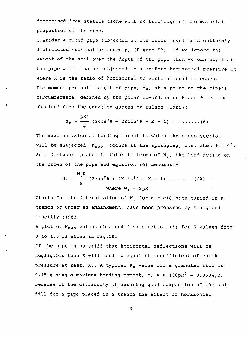
Consider a rigid pipe subjected at its crown level to a uniformly
distributed vertical pressure p, (Figure 5A). If we ignore the
weight of the soil over the depth of the pipe then we can say that
the pipe will also be subjected to a uniform horizontal pressure Kp
where K is the ratio of horizontal to vertical soil stresses.
The moment per unit length of pipe, Me, at a point on the pipe's
circumference, defined by the polar co-ordinates R and 8, can be
obtained from the equation quoted by Bulson (1985):-
pR 2
M 0 - (2cos2e + 2Ksin2e - K - I) ......... (6) 4
The maximum value of bending moment to which the cross section
will be subjected, Mmax, occurs at the springing, i.e. when e = 0 °
Some designers prefer to think in terms of Wc, the load acting on
the crown of the pipe and equation (6) becomes::-
WcR M 0 - (2cos2e + 2Ksin20 - K - i) ........ (6A)
8 where W c = 2pR
Charts for the determination of W c for a rigid pipe buried in a
trench or under an embankment, have been prepared by Young and
O'Reilly (1983).
A plot of Mma x values obtained from equation (6) for K values from
0 to 1.0 is shown in Fig.5B.
If the pipe is so stiff that horizontal deflections will be
negligible then K will tend to equal the coefficient of earth
pressure at rest, K 0. A typical K 0 value for a granular fill is
0.45 giving a maximum bending moment, M, = 0.138pR 2 = 0.069WcR.
Because of the difficulty of ensuring good compaction of the side
fill for a pipe placed in a trench the effect of horizontal
pressures acting on a trenched rigid pipe is usually ignored. In
effect K is taken as equal to 0 and the maximum bending moment
acting on the cross section as equal to 0.25pR 2 = 0.125WcR. If the
pipe is flexible enough to deflect horizontally outwards into the
soil then the value of K will increase leading to a consequent
reduction in the bending moment to which the pipe is subjected.
When K = 1.0 then M = 0 and the condition of an applied hydrostatic
pressure has been achieved.
2,2 Fl~xibl# DiDes
The basic problem considered in the current design approaches is
the two dimensional plane strain response of the circular buried
pipe cross section, otherwise termed the "pipe ring" Possible
detrimental longitudinal effects are briefly discussed in section
1.6 of the second report of this series, Smith (1991).
The type of structural failure experienced by a buried pipe is
affected by its degree of flexibility. A rigid pipe, with its
thick walls, usually experiences a structural failure caused by a
form of bending failure of the cross section. A buried flexible
pipe can be subjected to one of three possible failure modes;-
i. Excesssve deflections - the maximum deflection of the pipe ring must not exceed some specified allowable value.
2. Buckling failure - buckling of a pipe can occur in various ways, which are discussed later in this section. The compressive hoop stress within the pipe ring must be restricted to such a value that buckling failure will not occur.
3. 0verstressing of the pipe walls - due to the value of the compressive hoop stress becoming excessive. It should be noted that with flexible pipes this failure mode is generally less critical than (i) and (2).
Present practice is to check each condition and then choose a pipe
that will withstand the worst case.
2.2.1Spangler's deflection theory.
This theory is fully discussed in the CIRIA Report No. 78 and only
a brief resume will be given here.
Spangler (1941) used a discrete spring (Winkler) model to
represent the horizontal stiffness of the backfill soil and
suggested that the form of the pressure distribution around a
buried flexible circular pipe could be obtained by the following
assumptions:-
i) The vertical load/unit length, We, acting on the crown
is assumed to be uniformly distributed over an area equal to the
diameter of the pipe. W c is the summation of the effect of the
weight of the backfill soil above the pipe and the effect of any
vertical surcharge. The effect of the soil weight is determined
from Marston's theory (1913, 1930) which, in the case of
pipes in a trench, allows for the transference of part of the,
weight of the backfill to the undisturbed soil at the sides of
the trench. As is discussed in section 3.2.1 of this report,
CIRIA conservatively recommends that for most practical
situations this reduction of load can be ignored and the full
weight of the soil above the pipe assumed to act at crown level.
ii) The invert reaction is assumed to be vertical and to be
uniformly distributed over the width of the bedding of the pipe.
iii) The horizontal soil pressure is parabolically distributed
over the arc subtended by the central i00 degrees, varying from
zero to a maximum value of ksax/2 where ax is the total horizontal
deflection of the pipe ring. k s is generally known as the soil
stiffness or as the modulus of passive resistance although CIRIA
Report 78 refers to it as Spangler's modulus of subgrade reaction.
The assumed pressure distribution is illustrated in Fig.6.
5
Spangler developed the following equation for ax:-
KbWcR 3 ax = . .......... (7)
EI + 0.061ksR 4
where K b = the bedding factor whose value depends upon
= half the value of the bedding angle (in degrees) - See Fig.6
R = radius of unloaded pipe
I = Mom. of inertia of pipe wall per unit length (= t3/12
k s = Soil spring stiffness
E = Young's Modulus of the pipe material
Spangler developed a relationship between ~ and the bedding
factor Kb:-
0 15 22.5 30 45 60 90 K b 0.Ii 0.108 0.105 0.102 0.096 0.090 0.083
A linear regression analysis of these values gives the following
approximate formula:- K b : 0.11134 -0.00032~
With a smooth walled pipe the value of I per unit length is equal
to t3/12 where t = the wall thickness. However when a pipe wall is
corrugated its I value is considerably increased and this value
should be obtained from manufacturers' tables.
In order to establish a value for ks, CIRIA Report No. 78 uses the
approximate relationship E' = ksR where E' = Spangler's Modulus for
the soil.
Substituting E' = ksR and D = 2R, Eqn.(7) can be re-arranged as:-
KbWc
~x =
8EI/D 3 + 0.061E'
0.083W¢ or, when ~ = 90°: ~x =
8EI/D 3 + 0.061E'
EI/D 3, which only occurs in these modified forms of Eqn.(7),
involves the properties of the pipe and its value is called the
specific stiffness of the pipe and given the symbol E''
EI Hence E . . . . the specific stiffness of
D 3 the pipe per unit length
Substituting 8E'' for 8EI/D s in the modified equations leads to:-
0.083W¢ ~x = . ......... (7A)
8E'' + 0.061E'
Equation (7A) is the expression suggested by CIRIA and has the
general form:-
Factor x vertical load/unit length ~x =
Pipe stiffness factor + soil stiffness factor
The denominator therefore involves two constants, 8E'', the
structural stiffness of the pipe ring when its sides are
unsupported and 0.061E' the increase in stiffness with side
support from the backfill. It is interesting to look more closely
at these two parameters.
At the present time the upper limit of specific stiffness, E'', is
taken as ll,000N/m 2 and therefore, with the thickest recommended
flexible pipe, giving the maximum value of E'', it is seen that
8E'' cannot be greater then 88,000N/m 2
For backfills the lowest value of E' considered to be an
acceptable limit for work with buried pipes is 2 x 10⁶N/m 2 so
that the smallest possible value for 0.061E' is 122,000N/m 2
These two values represent the extreme values at either end of the
range of possible values. Obviously, at all times, the stiffness of
the backfill is of considerably more significance than the
structural stiffness of the pipe ring.
Although the simple representation of external loading as a
vertical load acting on the crown leads to a simple design
approach, it means that only the horizontal soil pressures
created by static vertical pressures are considered and the
effects of any horizontal components of earth pressure created
during the placing and compaction of the backfill are ignored.
This implies that the soil modulus, E', is taken as a constant
whose value can be either assumed or can be determined from
laboratory tests.
In fact the value of E' can be extremely variable as it is heavily
dependent upon the value of lateral pressure created during
backfilling.
A further point worthy of mention is that Spangler's approach
assumes a unique distribution of the equilibrium soil pressures
acting on the pipe cross section. In fact both the distribution
and the magnitude of these pressures are statically indeterminate
as they depend upon the properties of the pipe-soil system.
In summary it can be said that to apply the Marston-Spangler
theory realistically is not at all simple as neither the loads on
the pipe nor the properties of the backfill material are uniquely
defined. Nevertheless it must be stated that the direct application
of the Spangler method for the estimation of deflection values of
buried flexible pipes is widely used and considered satisfactory by
many engineers.
2.2.2 Barnard's method for pipe deflections. (1957)
The design method proposed by Barnard for buried flexible pipes is
used by the American Water Works Association and is described in
in their design manual, AWWA Manual MII, (1964). The method is
discussed in the CIRIA Report No. 78, where it is presented as an
alternative to the Spangler approach. The soil is considered to be
be elastic and the value of its Young's Modulus, Es, can be found
from the graphs, .prepared by Barnard, of typical axial stress/
strain relationships obtained from triaxial tests carried out on
different soil types, (Fig. SA).
The calculation procedure has the real advantage that it considers,
step by step, the way in which a steel pipe can resist earth loads.
Barnard considered three different cases of pipe resisting action:-
case I - When the wall thickness and the diameter of the pipe
selected to meet internal pressure and other service requirements
is such that the pipe is strong enough to carry all live and soil
loads without undue deflection.
Case II - When the pipe ring strength is sufficient to carry part
of the live and earth loads, but not all without undue deflection
To limit deflection values some side support must be provided by
the surrounding soil.
Case III- When the pipe is so weak that its cross section is a
completely flexible ring which can carry very little live and dead
load on its own without undue deflection. If acceptable values of
pipe ring deflection are to be achieved there must be full
mobilisation of the resistance that can be provided by the
surrounding soil. The resulting enveloping forces are essentially
radial, the pipe ring being confined and subjected to compressive
stress only. Barnard suggested that, for such situations, the
limiting value of compressive stress in the steel pipe ring
should be taken as 7,5001b/in 2, i.e. 52 x 106N/m z
As this report deals with flexible buried pipes Case III will be
the one most considered.
2.2.2.1 Barnard's shape factor
A buried flexible pipe that is perfectly round is not subjected to
a bending moment and 70, the value of the compressive stress
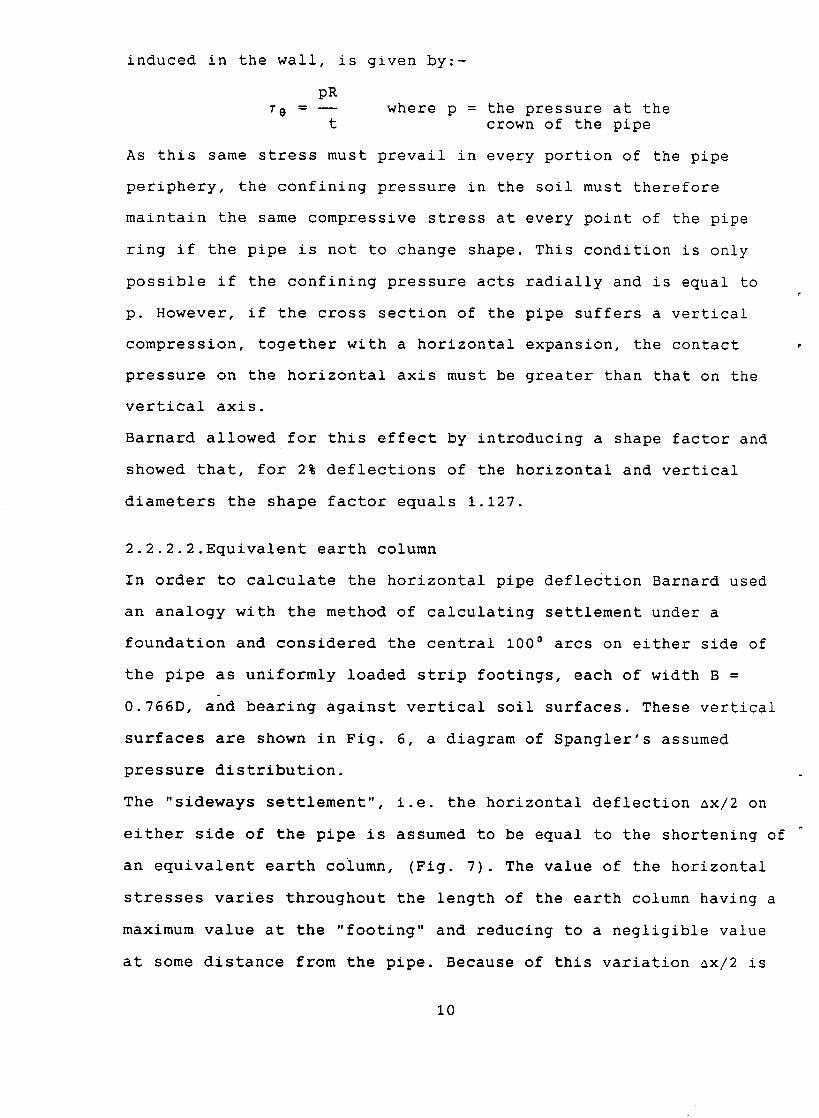
induced in the wall, is given by:-
pR T e - where p = the pressure at the
t crown of the pipe
As this same stress must prevail in every portion of the pipe
periphery, the confining pressure in the soil must therefore
maintain the same compressive stress at every point of the pipe
ring if the pipe is not to change shape. This condition is only
possible if the confining pressure acts radially and is equal to
p. However, if the cross section of the pipe suffers a vertical
compression, together with a horizontal expansion, the contact
pressure on the horizontal axis must be greater than that on the
vertical axis.
Barnard allowed for this effect by introducing a shape factor and
showed that, for 2% deflections of the horizontal and vertical
diameters the shape factor equals 1.127.
2.2.2.2.Equivalent earth column
In order to calculate the horizontal pipe deflection Barnard used
an analogy with the method of calculating settlement under a
foundation and considered the central i00 ° arcs on either side of
the pipe as uniformly loaded strip footings, each of width B =
0.766D, and bearing against vertical soil surfaces. These vertical
surfaces are shown in Fig. 6, a diagram of Spangler's assumed
pressure distribution.
The "sideways settlement", i.e. the horizontal deflection ax/2 on
either side of the pipe is assumed to be equal to the shortening of
an equivalent earth column, (Fig. 7). The value of the horizontal
stresses varies throughout the length of the earth column having a
maximum value at the "footing" and reducing to a negligible value
at some distance from the pipe. Because of this variation ax/2 is
i0
taken as equal to aL, the shortening of a uniformly stressed earth
column of length L = 1.25D.
Barnard used the symbols w h for the value of the uniform horizontal
contact pressure assumed to act on the earth columns and ~wh for
the corresponding strain.
In order to determine the value of Ewh the vertical overburden
pressure acting on the earth columns is considered analagous to a
triaxial cell pressure and w h as the axially applied compressive
stress. Barnard collected data of axial stress and strain values
obtained at different cell pressures from the results of triaxial
tests on various types of soil. In the original paper this
information was presented in graphical form and some of these
diagrams, converted to S.I. units, are reproduced in Fig.8A.
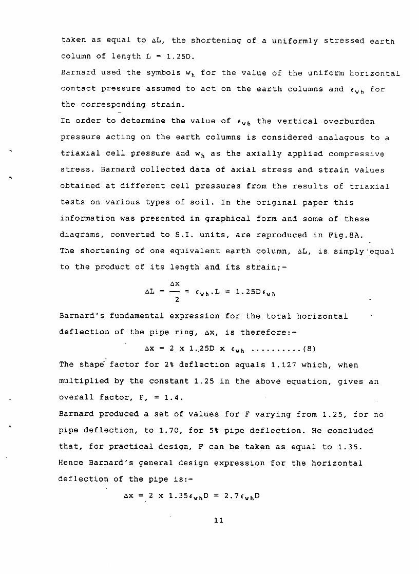
The shortening of one equivalent earth column, aL, is simply equal
to the product of its length and its strain;-
ax aL - = Ewh.L = 1.25D~wh
2
Barnard's fundamental expression for the total horizontal
deflection of the pipe ring, ax, is therefore:-
ax = 2 x 1.25D x ~wh .......... (8) °
The shape factor for 2% deflection equals 1.127 which, when
multiplied by the constant 1.25 in the above equation, gives an
overall factor, F, = 1.4.
Barnard produced a set of values for F varying from 1.25, for no
pipe deflection, to 1.70, for 5% pipe deflection. He concluded
that, for practical design, F can be taken as equal to 1.35.
Hence Barnard's general design expression for the horizontal
deflection of the pipe is:-
~x = 2 x 1.35~wh D = 2.7~whD
ii
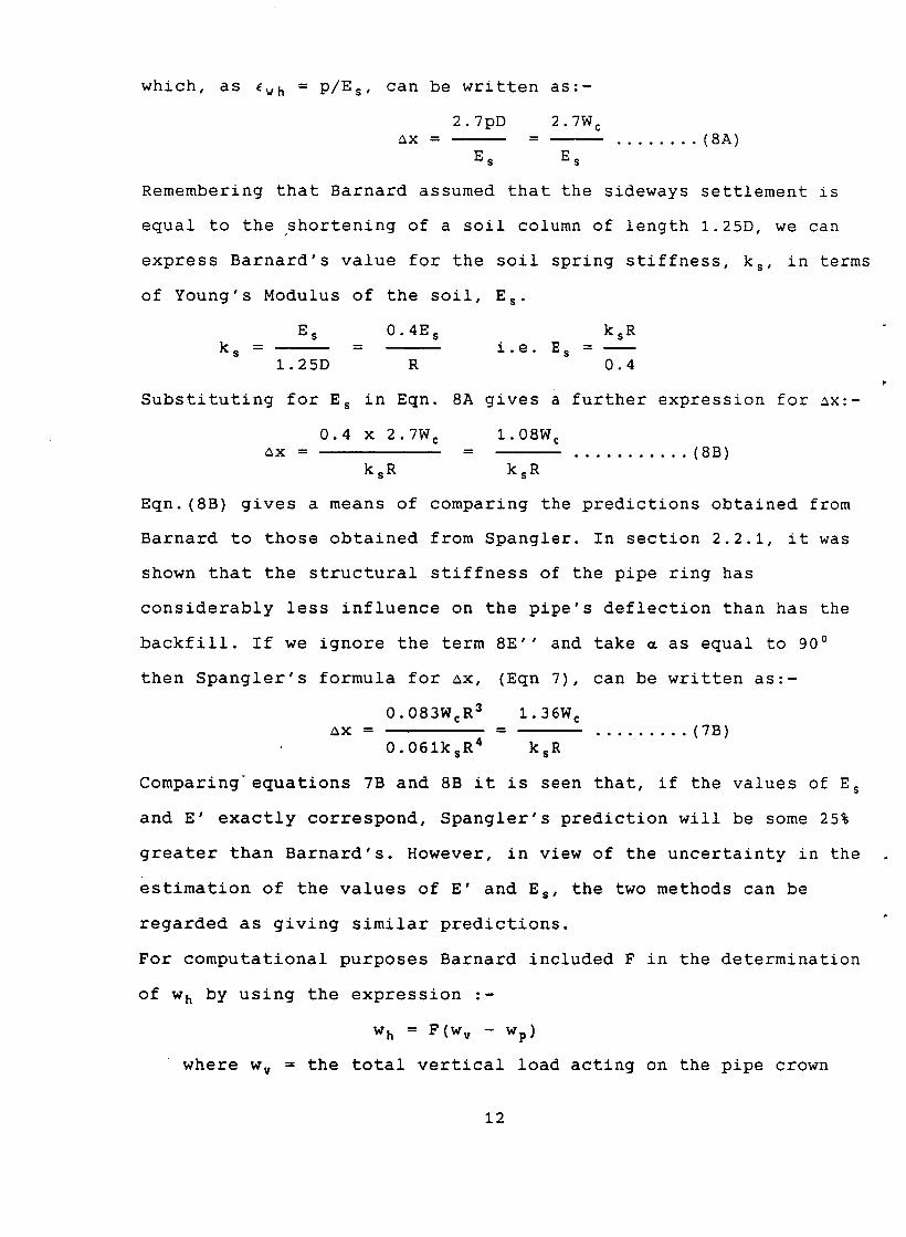
which, as ~wh = P/Es, can be written as:-
2.7pD 2.7W ~x -
Es Es
c
........ (8A)
Remembering that Barnard assumed that the sideways settlement is
equal to the shortening of a soil column of length 1.25D, we can
express Barnard's value for the soil spring stiffness, ks, in terms
of Young's Modulus of the soil, E s.
E s 0.4E s ksR k s - = i.e. E s -
1.25D R 0.4
Substituting for E s in Eqn. 8A gives a further expression for ~x:-
0.4 x 2.7W c 1.08W c ~x = = . .......... (8B)
ksR ksR
Eqn. (8B) gives a means of comparing the predictions obtained from
Barnard to those obtained from Spangler. In section 2.2.1, it was
shown that the structural stiffness of the pipe ring has
considerably less influence on the pipe's deflection than has the
backfill. If we ignore the term 8E'' and take ~ as equal to 900
(Eqn 7), can be written as:-
1.36W c - . ........ (7B)
ksR
then Spangler's formula for ax,
0.083Wc R3 ~X =
0.061ks R4
Comparingequations 7B and 8B it is seen that, if the values of E s
and E' exactly correspond, Spangler's prediction will be some 25%
greater than Barnard's. However, in view of the uncertainty in the
estimation of the values of E' and Es, the two methods can be
regarded as giving similar predictions.
For computational purposes Barnard included F in the determination
of w h by using the expression --
w h = F(w v - Wp)
where w v = the total vertical load acting on the pipe crown
12
wp = the ring load carried by the pipe when the pipe deflection equals 2%.
This value of w h is used to determine Ewh (from Fig.8A) and then
the horizontal pipe deflection, ax, which is simply equal to 2EwhD.
2,$ D~flec~iQ~ ~ime l~g factor
The value of ax, as determined from either Spangler's or Barnard's
approach, approximates to the instantaneous, or end of
construction, value of the horizontal deformation of the pipe.
Various studies have shown that the deformation of a buried
flexible pipe can increase with time due to the consolidation of
the surrounding soil. The effect is most noticeable with a non
pressurised pipe, i.e. one that is not carrying fluid under
pressure, and can be allowed for by multiplying the value of ax
by a factor, DL, known as the deflection lag factor. With a pipe
subjected to an internal pressure at least equal to the vertical
pressure caused by the soil weight the consequent re-rounding of
the pipe ring tends to nullify time effects and the horizontal
deformation of the pipe remains sensibly constant throughout its
life, at a value of the order of ax.
The generally accepted rule in buried flexible pipe design is, in
the absence of soil tests, to take D L as equal to 1.5 for
non-pressurised pipes and as 1.0 for pressurised pipes. It should
be remembered that D L is only applied to the value of the
deflection caused by dead loading and not to any caused by
superimposed live loading.
2,4 Bucklinq Qf ~ circular DiDe
2.4.1 Pipe with no radial support
The classic ring buckling formula for an unsupported circular ring
subjected to external hydrostatic pressure only was derived by Levy
13
in 1884 and is quoted as Eqn. (5) at the end of Appendix II.
3EI Pb -
R 3
For a long pipe the expression becomes:-
3EI 24EI/D 3
Pb = = . ..... (9) (i- vp2)R 3 (I- vp 2)
where Pb = critical external pressure required to cause buckling.
vp = Poisson's ratio of the pipe material.
Eq. (9) is referred to as Timoshenko's buckling equation and is
simply the plane strain version of the plane stress equation (5).
2.4.2 Pipe with elastic radial support
The simplest model of buried pipe buckling is that of a ring
loaded hydrostatically and supported by radial springs of unit
stiffness, k s , as shown in Fig.9. Such a ring usually tends to
buckle by forming a series of symmetrical ripples, or waves,
around its circumference, of the form shown in Fig.10A, whilst
its cross section remains sensibly circular. The number of waves
created can vary from 2 upwards and they are essentially
sinusoidal in shape being of the form shown in Fig.10. Another
form of buckling is the formation of a localised single wave,
illustrated in Fig.10B.
The multi-wave mode of buckling is the simplest to analyse and is
also more critical than the single wave mode, provided it is
assumed that the soil spring stiffness is constant for both inward
and outward displacements of the pipe wall. Single wave buckling
involves a much larger deformation and is therefore sensitive to
any initial out-of-roundess of the pipe wall. It is for this reason
that soil-loaded pipes which intially buckle in a multi-wave mode
14
invariably collapse in a single wave mode which should really be
regarded as a post-buckling behaviour.
Many researchers have considered the problem of multi-wave mode
buckling, some of the more important being:- Link (1963),
Cheney (1963), Meyerhof and Baikie (1963) and Duns (1966).
For large values of n the plane strain expression for Pb is
generally accepted to be:-
/ ksREI Pb = 2 / ............. (i0)
~/ R3(I - vp 2 )
At the present time, there is not a design formula for single-wave
buckling that is comparable in simplicity to the one used for
multi-wave buckling, i.e. Eqn. (i0).
The major problem with the use of Eqn. (i0) is the determination of
a realistic value for k s as its value varies with both the soil
properties and the size of the loaded area, Terzaghi (1955).
Various writers Habib & Luong (1965, 1966); Luscher (1966);
Chelapati (1966) have proposed the following relationship for plane
strain:- m ,
ksR = (i- VS 2 )
where v s = Poisson's ratio for the soil.
Current practice is to use the same k s value for the buckling
calculation as is assumed for the deflection calculation which
means that the formula for buckling used in CIRIA Report No 78 is
Eqn. (I0) with E' substitued for ksR. There is no attempt to allow
for the reduction in buckling resistance due to any out of
roundness of the pipe's cross section caused by non-uniform
loading in the ground.
More recent investigations of buckling by other researchers have
led to other expressions for Pb- The problem is that all of them
15
depend heavily upon unreliable, and often unrelated, soil stiffness
measurements and it is almost impossible to use the difference
between calculated and measured results to determine whether there
are errors in the particular theory used or whether there are
errors in the values assumed for the soil parameters. This
difficulty has been overcome in the design method evolved by Gumbel
(1983) in which the interpretation of buried pipe buckling data
can be carried out without reference to the value of E'
2.4.3 Snap-through buckling
With some pipes excessive deflection at the crown can lead to a
sudden, single wave, snap-through buckling failure as illustrated
in Fig.ll, which, like single wave buckling, is really a type of
post buckling behaviour. This form of failure is not a feature of
reinforced plastic pipes where deformations tend to occur gradually
and although corrugated metal culverts can fail by snap-through
buckling the effect does not occur until the crown deflection is at
least 0.2D. The main risk of a snap-through failure is with smooth
thin-walled metal pipes where it can occur at relatively low values
of crown deflection. Design practice is to limit such deflections
to not more than 0.05D but it should be noted that full scale load
tests by Watkins & Moser (1969), Howard (1972) and Crabb and Carder
(1985) illustrated that a flexible pipe wall can fail by buckling
or crushing at deflections anywhere between 0.01D to 0.2D. As the
response is generally non-linear, a pipe that fails at 0.2D crown .
deflection will have a factor of safety considerably less than 4
when the crown deflection equals 0.05D.
2,2 Rinq compression theorv
It is iliustrated in Appendix II that a pipe subjected to a
16
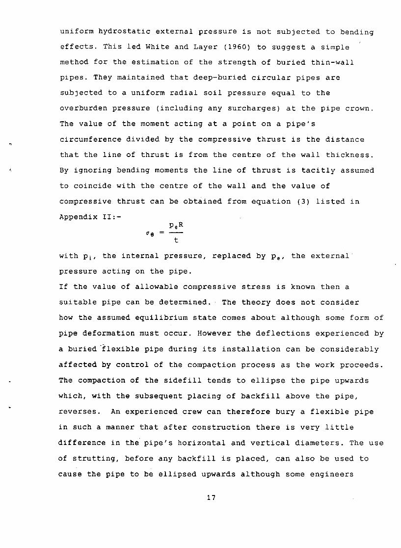
uniform hydrostatic external pressure is not subjected to bending
effects. This led White and Layer (1960) to suggest a simple
method for the estimation of the strength of buried thin-wall
pipes. They maintained that deep-buried circular pipes are
subjected to a uniform radial soil pressure equal to the
overburden pressure (including any surcharges) at the pipe crown.
The value of the moment acting at a point on a pipe's
circumference divided by the compressive thrust is the distance
that the line of thrust is from the centre of the wall thickness.
By ignoring bending moments the line of thrust is tacitly assumed
to coincide with the centre of the wall and the value of
compressive thrust can be obtained from equation (3) listed in
Appendix II:- Pe R
~8 = t
with Pi, the internal pressure, replaced by Pe, the external
pressure acting on the pipe.
If the value of allowable compressive stress is known then a
suitable pipe can be determined. The theory does not consider
how the assumed equilibrium state comes about although some form of
pipe deformation must occur. However the deflections experienced by
a buried'flexible pipe during its installation can be considerably
affected by control of the compaction process as the work proceeds.
The compaction of the sidefill tends to ellipse the pipe upwards
which, with the subsequent placing of backfill above the pipe,
reverses. An experienced crew can therefore bury a flexible pipe
in such a manner that after construction there is very little
difference in the pipe's horizontal and vertical diameters. The use
of strutting, before any backfill is placed, can also be used to
cause the pipe to be ellipsed upwards although some engineers
17
consider the practice to be unnecessary or even undesirable.
However it should be noted that, in some situations, not to
consider possible buckling and/or deflections of the pipe ring can
lead to a serious over estimation of the pipe strength.
3 THE CIRIA DESIGN PROCEDURE FOR BURIED FLEXIBLE PIPES
At the present time the publications mainly referred to in the
U.K. for the design of buried flexible pipes are the CIRIA Report
No.78 (1978), the American Waterworks Association's manual MII
(1964), and, more recently, the Water Research Centre's Manual
(1988) .
A summary of the design procedures suggested in the CIRIA Report
Report now follows. The Report uses plane stress formulae and
defines thin-walled pipes as those having specific stiffnesses,
EI/D ~, within the range 400 to ll,000N/m 2 which, for mild steel
pipes, with E = 0.21 x 10¹²N/m 2, means a diameter to thickness
ratio, D/t, ranging from 350 to 115.
Although the Report acknowledges that a draft British standard is
considering the use of plastic pipes with specific stiffnesses as
low as 250N/m 2 it stresses that the design procedure it suggests is
based on practical experience obtained from buried pipes with
specific stiffnesses of not less than 2000N/m 2 and is therefore
only applicable to such pipes. This means that, for mild steel
pipes, the D/t ratio should not be greater than 200 or so.
5,1 ReQuiro~ data
The following information is required:
The pipe diameter, the pipe material and its properties.
Depth of cover and properties of backfill.
18
Superimposed loadings and the maximum and minimum internal
pressures to which the pipe will be subjected.
Maximum and minimum groundwater levels
3,2 External loads Qn bides
The total pressure, Pt, acting at the crown of a buried pipe is
equal to the weight of the backfill plus the effects of any uniform
surcharges and concentrated loads, both dead and superimposed,
that act above the pipe plus the value of the ground water pressure
acting at the invert level of the pipe.
3.2.1 Soil weight
The weight of the backfill is taken to be equal to wH where H
is the height of soil above the pipe crown and w is the unit
weight of the fill. For a cover depth between 0.25 to 1.0D an
equivalent height of soil, H + 0.107D, should be used. (See
Appendix III). H should normally not be less than 1.0m unless
load-relieving slabs are used or other precautions taken.
The CIRIA Report points out that, for large depths of cover, it is
possible to use Marston and Anderson's theory (1913) to allow for
alleviation in the weight of the soil on the pipe due to arching
effects. A simple approximation to this theory is to assume that
the full weight of the fill acts to a certain depth, z0, and that,
at further depths of cover, the pressure remains constant and equal
to wz 0. z 0 is obtained from the formula:-
D Z 0 =
2Katan#
where K a = The coefficient of active earth pressure
# = Angle of shearing resistance of fill
For a set of typical soil values z o : 2.6D and the CIRIA Report
19
recommends that, for most practical flexible pipe situations, the
total vertical pressure of the soil should be taken as equal to wH
and assumed to act at crown level, which is the same procedure as
that proposed by Barnard (1957).
3.2.2 Uniform surcharges
Uniform surcharges of great extent and applied at the ground
surface are assumed to be transferred unaltered to the pipe. If
such a surcharge is to be a permanent feature then it is regarded
as dead loading but if it is temporary, as may occur during
construction, then its transitory affect should be allowed for in
the design.
If a uniform surcharge is of limited extent then the pressure that
it will exert on the buried pipe will tend to diminish with depth.
This effect can be determined by the use of influence factors such
as those proposed by Fadum (1941).
3.2.3 Concentrated loads
Concentrated loads are assumed to spread in accordance with the
Boussinesq theory (1885).
The all round pressure applied to the pipe at a point on its crown,
PL, due t 9 a concentrated load P acting at the ground surface, is
taken to be:-
3PH 3
PL - 2~C 5
where c is the distance from the point of application of P
to the point on the pipe crown.
3.2.4 Traffic and other transient surcharge loads
Surcharge loads on buried flexible pipes are normally assumed to be
the same as those on buried rigid pipes and can therefore be
20
obtained from published charts or tables.
Young and O'Reilly (1983) prepared sets of vehicle load charts to
cover road loads (three classes), railway loads (two classes) and
construction traffic loads. The chart that deals with road loadings
is reproduced in Fig. 12. Simplified tables using these charts have
since been published, (Young, Brennan and O'Reilly, 1986).
It will be obvious to the reader that the chart selected for
design should be the one that best represents the worst traffic
loading conditions that the buried pipe will experience. In this
connection it should be noted that Trott & Gaunt (1976) found
that, on large civil engineering works, buried pipes may well be
subjected to their highest life-time loads from contractor's
plant during construction.
3.2.5 Groundwater
Groundwater pressure will only affect the pipe if the water
table is above the invert level. If the water table is above the
crown of the pipe then, due to submergence, there is a reduction in
the apparent weight of the soil below ground water level and a
resultant reduction in the value of Pt, to which must be added the
value of the ground water pressure.
The ground water pressure, Pw, varies around the pipe with a
maximum value at the invert level equal to ~wh where h is the
height of the water table above the invert. This maximum value of
Pv should be added to the reduced value of Pt if submergence is
allowed for. However the procedure involves the determination of
the precise level of the permanent water table and the effect of a
temporary lowering of the water table during installation should
also be checked.
The approach suggested in the CIRIA Report is that submergence
21
effects should be ignored and that the soil's contribution to the
value of Pt taken as equal to wH, where w is the saturated unit
weight of the soil. This approach is justified when it is
considered that any theoretical increase in the value of Pt, and
hence in the theoretical value of the applied horizontal stress,
due to an effective stress analysis, is likely to be of the same
order as the uncertainty in the value asumed for the horizontal/
vertical pressure ratio.
This practice of ignoring submergence and simply regarding the soil
as saturated has been adopted by both the American Water Works
Association in their Design Manual MII (1964) and by the British
Water Research Centre (See Section 4). Gumbel (1983) also uses
this approach.
3.2.6 Vacuum conditions
If the absolute pressure in the pipe can reduce to a value
(A - pq) where A is the normal atmospheric pressure then the
pressure pq is treated as a uniform live load applied at the
ground surface, i.e. pq should be added to the value of Pt-
3.3 Determination Q~ m~ximDmdiameter/w~ll thickness ratio. D/~
A buried pipe is designed for one of two possible situations. It
will either be subjected to internal hydraulic pressure as it
carries a fluid under pressure, or it will be open to the
atmosphere, such as a culvert used as a pedestrian underpass or
when a watermain is drained.
For a pipe subjected to internal hydraulic pressure the maximum D/t
ratio is obtained from eqn. (3) in the form:-
D 2f a
t Pi
22
where fa = allowable circumferential (in this case tensile) stress
in the pipe walls.
Pi = internal fluid pressure within the pipe
The pipe is then checked to ensure that it will be safe to
withstand the circumferential compressive stress induced in its
wall by the action of the total, all-round, external pressure, Pt-
Buried pipes which will only be subjected to internal atmospheric
pressure are designed to withstand the action of the external
pressure, Pt, only and the maximum D/t ratio is obtained from the
expression:- D 2f a
t Pt
where fa = allowable circumferential (i.e. compressive) stress.
3.4 Determination Qf DiDe sDecific stiffness
The formula for the specific stiffness of the pipe, E'', is:-
EI m t l
D 3
As already discussed, the design procedure suggested by the CIRIA
Report No.78 is intended to cover buried pipes of specific
stiffnesses ranging from 2000 to ll000N/m 2. .
3.5 Determin@~ion Q~ the Gri~iG~l buGkling Dressure
The critical buckling pressure is the value of externally applied
hydraulic pressure that will cause buckling of the pipe walls and
can be obtained from Eqn.(10). The plane stress equivalent of this
equation is:-
/ ksREI pb = 2 /
~/ R 3
and putting E' = ksR and E , , _
8El
R 3
gives:-
23
Pb = 2 4 8E'E'' which is the formula suggested in the CIRIA
Report.
The soil modulus, E', is a variable with a value that depends upon
the type of soil, its density and the in-situ effective vertical
stress which varies with depth. CIRIA suggests that, for
preliminary design, a minimum value of i0 x 106N/m 2 can be used for
E' Higher values for E' are justified when the soil is well
compacted and can be taken as equal to the elastic modulus of the
fill, as determined from triaxial tests carried out on 100mm
diameter samples compacted to the expected insitu density.
If the pipe wall were unyielding then fb, the compressive stress
created by Pb, would be equal to PbD/2t and the CIRIA Report
therefore suggests that an expression for fa, the allowable
compressive stress in the pipe wall, is:-
1 fy x fb fa - x
FS fY + fb
Where FS = the factor of safety against buckling (usuallytaken as 3)
fy = the yield stress of the pipe material
It is this formula for fa which effectively limits the use of the
suggested design procedure to pipes with specific stiffnesses
between 2,000 and ii,000 N/m 2 The formula is not acceptable for
very flexible pipes whose high values of slenderness ratio
dictate that the risk of buckling is critically dependent upon
any initial imperfections that may have caused departures from
the circular shape of the cross section of the pipe.
~,~ D@fl@G~ion calcula~iQn~
The expressions for the total horizontal deflection, ax, by
24
Barnard and Spangler are both recommended by CIRIA and have been
discussed in sections 2.2.1 and 2.2.2. It should be noted that,
the value for ax calculated for dead loading should be increased
by multiplying by 1.5 (the deflection lag factor) unless the pipe
is to be subjected to an internal pressure at least equal to the
vertical soil pressure acting at the crown of the pipe, see
section 2.3.
The load to which a buried pipe will be subjected will be
applied in stages and it is convenient to modify the deflection
formula to use the term ~p where ~p is the change in the pressure
acting at the crown due to a change in the crown load, ~W c.
Now 5p.D = ~W c so the expression becomes:-
ax 0. 083 ~p - . . . . . . . . . . . ( Z l )
D 8E'' + 0.061E'
where ax/D is known as the horizontal diametral change.
Two separate deflection calculations are necessary for a buried
flexible pipe.
The first one is to estimate the amount of horizontal diametral
change that will occur during the placing and backfilling of the
pipe. The compaction of the side fill tends to compress the pipe
horizontally and to increase its vertical diameter whilst the
placing of backfill above the pipe tends to return it to its
original circular cross section. For this stage of construction the
diametral change can be estimated from eqn. (ll) with ~p replaced by
wH.
With corrugated steel pipes it is generally not necessary to make
this calculation. For other types of pipes, such as pipes with a
brittle protective coating, the limits of allowable deflections can
be obtained from the manufacturers' tables.
25
The second calculation is the estimation of the cycle of diametral
change that the pipe will experience under the action of live
loadings. The procedure is to determine a relevant value for ~p,
from published tables, etc. and to determine ax/D from Eqn. (ii).
Data presently available indicates that values of ax/D less than
0.03 do not affect either brittle pipe coatings, such as cement
mortar, or the compacted fill in which a pipe is encased.
9,7 MinimDm DiDe stiffness Qr h~n~linq stresses
Experience in the construction of corrugated steel plate culverts
indicate that for pipes of 3m diameter or less the specific pipe
stiffness should be such that E''D is greater than 4,000 N/m unless
some form of bracing is employed.
Example ~ - Spangler's approach
Data Pipe material - unlined mild steel
Diameter = 3.0m
Internal water pressure = 1,500kN/m a
Cover depth = 3.5m
Unit weight of granular fill = 20kN/m s
Ground water level - below invert of pipe
_ The pipeline will cross under a dual carriageway which will be subjected to main road loading.
Steel properties
E = 0.21 x 10*2N/m 2
f¥ = 240 x 106N/m 2
Backfill properties
E' = i0 x 106N/m 2
M~ximDm D/t ratio
Allowable tensile stress = fa = fy/2 = 120 x 106N/m 2
26
D 2f a 2 x 120 x 106 Maxm.
t P i 1.5 x 106 = 160
Hence: minimum t - 3.0
160 - 0.0188m = 20mm
I =
t 3 0.023
12 1 2 = 6.667 x i0- m 3
EI m f t --
D 3 3.03
0.21 x 10 *2 x 6.667 x 10 -7 = 5,185N/m 2
This value is within the range 2,000 to ll,000N/m 2 and is
therefore acceptable.
Ext~rn~l Dressur@ Pt
Soil load = wH = 20 x 103 x 3.5 = 70 x 103N/m 2
Uniform surcharge equivalent to main road loadings with H = 3.5m (From Fig.12) = 24 x 103N/m 2
Vacuum conditions (worst possible = -i atmosphere) = i00 x 103N 2
Pt = total = 194 x 103N/m 2
Buckling Dressure
Pb = 24 8E'E'' = 2 4 8 x i0 x 106 x 5185
= 1.288 x 10⁶N/m 2
This corresponds to a wall stress value, fb:-
PbD fb =
2t
1.288 x 3 x 106
2 x 0.02
= 96.6 x 10⁶N/m 2
NOW allowable compressive stress, fa - 1
FS
fy x fb
fY + fb
i.e. fa = 1 [240
3
x i0 e x 96.6 x i0 e]
] (240 + 96.6)106
= 23.0 x 10⁶N/m 2
NOW Pb = 2fat/D which means that the maximum value of radial
27
pressure that can be withstood by the pipe is equal to:-
2 x 23.0 x 0.02 x 106
3.0
= 306 x 10SN/m 2
Pt = 194 x 103N/m 2 :- the chosen pipe is satisfactory.
Han¢linq stresses
E'' = 5,185N/m 2 so E''D = 5185 x 3.0 = 15,555N/m, which is
greater than 4,000 and therefore O.K.
D@fleGtion values
Considering the weight of the soil only:-
~p = 20 x 3.5 = 70kN/m 2 = 70 x 10SN/m 2
E'' = 5,185N/m 2 and E' = i0 x 106N/m 2
Hence 8E'' + 0.061E' = 8 x 5185 + 0.061 x i0 x 106
= 651 x 10SN/m 2
0.083 x 70 x i0 s x 3 x I0 s ax = = 26.7mm
651 x i0 s
Cyclic change in diameter due to live loading:-
~p = 24kN/m 2 = 24 x 10SN/m 2
and ax = 9.2
Totab. pipe deflection = 26.7 + 9.2 = 35.9 : 36mm
If the pipe was coated these values of deflection would now be
checked against the manufacturer's tables as to their suitability.
It should be noted that as the internal water pressure is
considerably greater than the vertical soil pressure acting on the
crown of the pipe, deflection lag effects can be ignored, i.e. the
value of D L has been taken as 1.0.
Ex~mpl~ ~ - Barnard's approach
The suitability of the pipe section selected by Spangler's method
28
in Example 3 will now be checked using Barnard's approach.
Data Pipe material - unlined mild steel
Diameter = 3m
Wall thickness = 20mm
Internal water pressure = 1,500kN/m 2
Cover depth = 3.5m
The pipeline will cross under a dual carriageway which will be subjected to main road loading.
Ground water level - below invert of pipe.
Steel properties
Yield stress, fy = 240 x 1012N/m 2
B~ckfill proDer~i~$
Granular fill
Unit weight = 20kN/m z '
Stress/strain relationships from Fig.8A
W~ll thickness
Thickness of wall required for internal water pressure.
Allowable tensile stress, fa, = fy/2 = 120 x 106N/m 2
For minimum wall thickness, t: fa
Required t = 1500 x 3
2 x 120
P i D
2t
= 18.75mm
Actual value used = 20mm ....... O.K.
SteD l
The total vertical pressure, Wv, acting on the top of the pipe is
the sum of the dead load pressure, w v and live load pressure, WvL '
In example 3 the value of WvL was found from Young & O'Reilly's
chart (Fig.12) to be = 24kN/m 2'
w v = 20 x 3.5 + 24 = 94kN/m 2
29
Step
The limiting height of cover H which the structural stiffness of
the pipe can support with 2% deflection without side support is
obtained from Fig.8B and equals 0.47m. This height is now used to
determine the value of vertical pressure, wp, that the pipe can
support.
If wp > w v then the pipe can carry the vertical loads on its own
and satisfies the conditions of Case I.
If wp < w v then aid from the active pressure of loose fill is
necessary and the pipe must be considered as Case II.
wp = 20 x 0.47 = 9.4kN/m 2
wp (9.4kN/m 2) < w v (94kN/m 2) : active pressure must be considered.
SteD
Wa, the active pressure value determined, is that acting at the
level of the pipe's horizontal axis and is equal to the vertical
pressure, due to dead load only, times a factor (either 0.5 for
clay or 0.33 for sand).
If (wp + Wa) > w v then the pipe can carry its vertical load with
the aid of loose fill around it and satisfies the conditions of
Case II.
If (wp +-wa) < w v then the pipe requires more aid from the side
fill and must be considered as Case III.
Vertical pressure at pipe axis = 20(3.5 + 1.5) = 100kN/m 2
Sidefill is sand, hence w a = 0.33 x i00 = 33kN/m 2
(wp + Wa) = 9.4 + 33 : 42kN/m 2 < w v (94kN/m 2)
The pipe must be considered as a Case III situation.
Step
If the limiting compressive stress is taken as 52 x 103kN/m 2
(See 2.2.2 Case III) then the limiting height of cover, Z, is
30
obtained from the expression:-
52 x 103 x 2t 20 x 103 x Z =
D
If H > Z £hen the assumed pipe is too weak and must be rejected.
If H < Z then the assumed pipe is satisfactory.
52 x i000 x 2 x 20 Z = = 34.7m
20 x 3 x i000
H = 3.5 hence the assumed pipe is satisfactory.
SteD
The contact pressure, wh, is determined from the formula:-
w h = F(w v - wp)
Considering dead load only, with F = 1.35:-
Vertical pressure at crown of pipe = wv = 70kN/m 2
Hence w h = 1.35(70 - 9.4) = 81.8kN/m 2
Considering dead load + surcharge, with F = 1.35:-
Vertical pressure at crown of pipe = w v = 70 + 24 = 94kN/m 2
Hence w h = 1.35(94 - 9.4) = ll4.2kN/m 2
Deflection values
SteD
a) Deflection of pipe due to dead loads only
With dead load only: w h = 81.8kN/m 2
Vertical pressure at hoz. axis of pipe = 20(3.5+1.5) = 100kN/m 2
which is regarded as the minor principal stress, ~3, whilst w h
(81.8kN/m 2) iS regarded as the deviator stress, (~z - ~3)-
The value of ~wh that corresponds to these stress values can be
estimated from Fig.8A (for well graded sand) and is appoximately
0.7%. Hence the deflection of the pipe due to dead load is in the
order of 2 x .007 x 3000 = 42mm.
31
b) Deflection of pipe under dead and superimposed loads
With dead load + surcharge: w~ = ll4.2kN/m 2
Vertical pressure acting at centre of pipe (due to dead load only)
= 100kN/m 2, which is regarded as ~3 whilst w h (ll4.2kN/m 2) is
regarded as (~I - ~3)- The value of ~wh that corresponds to these
values is found from Fig.8A and equals 0.9%.
The total horizontal deflection of the pipe is therefore:-
ax = 2 x .009 x 3000 = 54mm.
c) Cyclic change in diameter
Due to the superimposed loading the cyclic change in diameter
= 54 - 42 = 12mm.
4 WATER RESEARCH CENTRE DESIGN PROCEDURE FOR BURIED
FLEXIBLE PIPES
In 1988 the Water Research Centre published a manual which deals
with the design of buried, rigid, semi-rigid and flexible water
carrying pipes. As with the design methods recommended by CIRIA,
the methods proposed by WRC are mainly concerned with the design of
the pipe ring although possible longitudinal effects are discussed. °
The Manual stresses that it is only concerned with water carrying
pipes and also that, whilst its design philosophy is of general
application, the assumed performances of materials, quality levels
and installation procedure are based on UK practice and may not be
applicable in non UK situations. A summary of the manual's
recommendations for buried flexible pipe design is given below.
i) A trial pipe section is selected by a consideration of the
proposed internal water pressure value and possible handling
stresses during installation, (As in both examples 3 and 4). Sudden
32
stoppages in the water flow, due to the operation of a valve, etc.,
can produce surge pressures which can be either positive or
negative and these should be allowed for.
ii) The design limits for the pipe are determined. The value of
the critical buckling pressure is calculated whilst the value of
allowable deflection is either taken to be 3% or is established
from manufacturers' tables. As has been discussed, bending effects
are rarely considered for flexible steel pipes.
iii) Values for DL, the deflection lag factor, and DR, the
re-rounding factor, are established.
iv) A suitable backfill material is selected.
v) The buckling stability is examined.
vi) The initial and long-term pipe deflections are determined,
and checked against their permissible values.
4,~ Backfill materi~l selection
The Water research Centre's manual uses E', Spangler's soil
modulus, for its calculations and tabulates a set of conservative
values for design work. Those values applicable to flexible buried
pipes are given in Table i. It should be noted that, in the table,
BSma isthe maximum dry density achieved in the 2.5kg rammer
compaction test described in BS1377: Part 2 (1990).
Fine material is that material passing the 63um sieve.
33
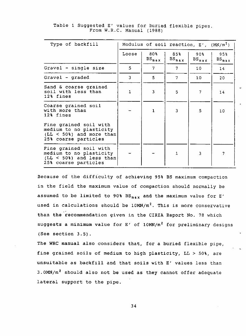
Table 1 Suggested E' values for buried flexible pipes. From W.R.C. Manual (1988)
Type of backfill
Gravel - single size
Gravel - graded
Sand & coarse grained soil with less than 12% fines
Coarse grained soil with more than 12% fines
Fine grained soil with medium to no plasticity (LL < 50%) and more than 25% coarse particles
Fine grained soil with medium to no plasticity (LL < 50%) and less than 25% coarse particles
Modulus of soil reaction, E', (MN/m 2)
Loose
3
80% BSmax
7
5
3
1
85% BSmax
90% BSmax
i0
i0
7
5
95% BSmax
14
20
14
i0
Because of the difficulty of achieving 95% BS maximum compaction
in the field the maximum value of compaction should normally be
assumed to be limited to 90% BSma x and the maximum value for E'
used in calculations should be 10MN/m 2. This is more conservative o
than therecommendation given in the CIRIA Report No. 78 which
suggests a minimum value for E' of 10MN/m 2 for preliminary designs
(See section 3.5).
The WRC manual also considers that, for a buried flexible pipe,
fine grained soils of medium to high plasticity, LL > 50%, are
unsuitable as backfill and that soils with E' values less than
3.0MN/m 2 should also not be used as they cannot offer adequate
lateral support to the pipe.
34
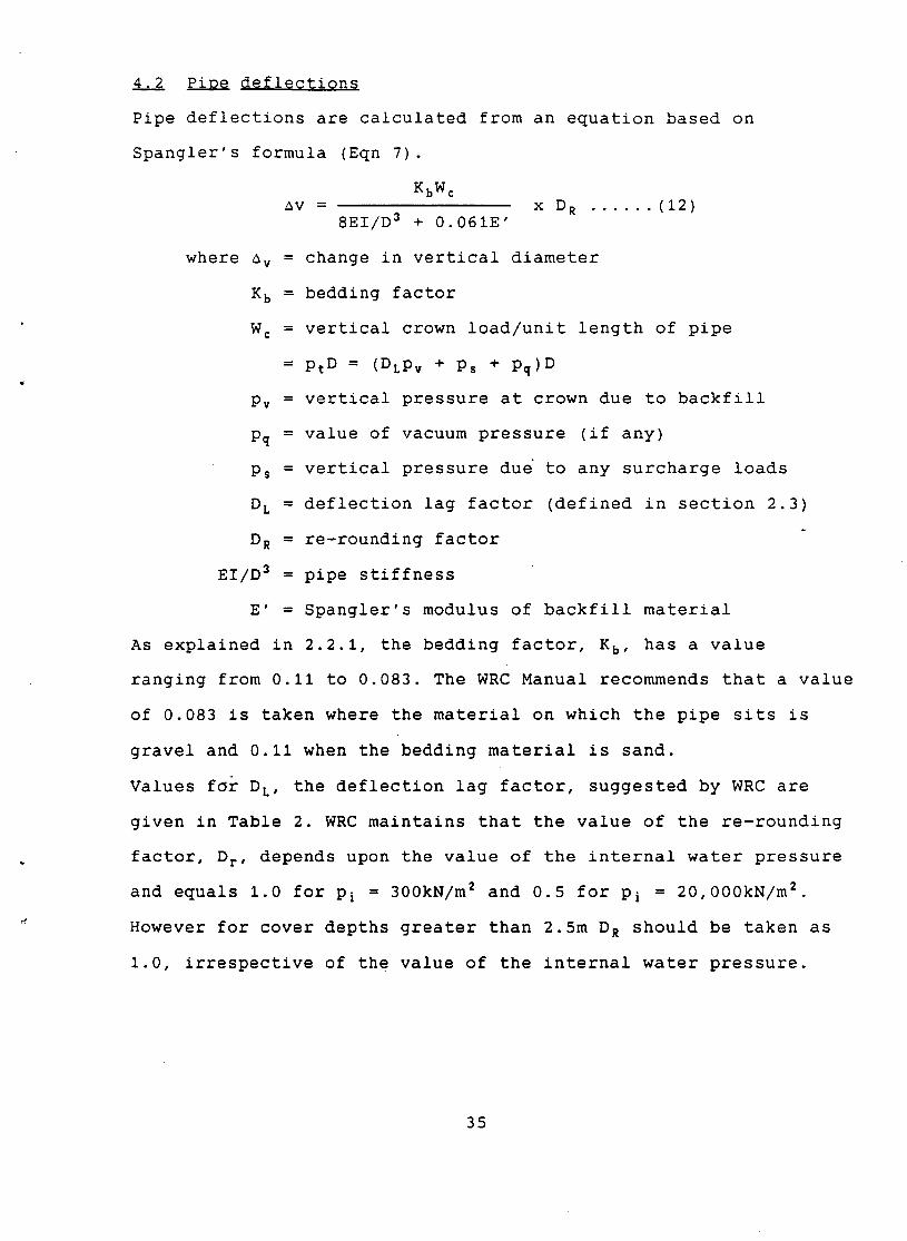
4,2 Pipe deflections
Pipe deflections are calculated from an equation based on
Spangler's formula (Eqn 7).
KbW¢ av = x D R ...... (12)
8EI/D 3 + 0.061E'
where av = change in vertical diameter
K b = bedding factor
W c = vertical crown load/unit length of pipe
= Pt D = (DLPv + Ps + pq)D
Pv = vertical pressure at crown due to backfill
pq = value of vacuum pressure (if any)
Ps = vertical pressure due to any surcharge loads
D L = deflection lag factor (defined in section 2.3)
D R = re-rounding factor
EI/D 3 = pipe stiffness
E' = Spangler's modulus of backfill material
As explained in 2.2.1, the bedding factor, KB, has a value
ranging from 0.Ii to 0.083. The WRC Manual recommends that a value
of 0.083 is taken where the material on which the pipe sits is
gravel and 0.ii when the bedding material is sand.
Values for DL, the deflection lag factor, suggested by WRC are
given in Table 2. WRC maintains that the value of the re-rounding
factor, Dr, depends upon the value of the internal water pressure
and equals 1.0 for Pi = 300kN/m2 and 0.5 for Pi = 20,000kN/m2
However for cover depths greater than 2.5m D R should be taken as
1.0, irrespective of the value of the internal water pressure.
35
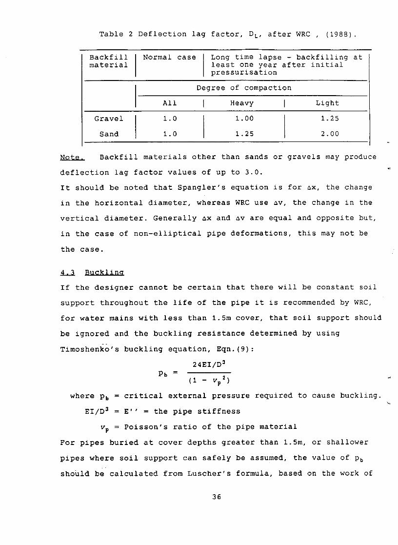
Table 2 Deflection lag factor, D L, after WRC , (1988).
Backfill Normal case Long time lapse - backfilling at material least one year after initial
pressurisation
I Degree of compaction
All I Heavy I Light
Gravel I 1.0 1.00 1.25
Sand I 1.0 1.25 2.00
Note. Backfill materials other than sands or gravels may produce
deflection lag factor values of up to 3.0.
It should be noted that Spangler's equation is for ax, the change
in the horizontal diameter, whereas WRC use av, the change in the
vertical diameter. Generally ax and av are equal and opposite but,
in the case of non-elliptical pipe deformations, this may not be
the case.
4,~ BDcklina
If the designer cannot be certain that there will be constant soil
support throughout the life of the pipe it is recommended by WRC,
for water mains with less than 1.5m cover, that soil support should
be ignored and the buckling resistance determined by using
Timoshenko's buckling equation, Eqn.(9):
24EI/D 3
p5 = (I - vp 2)
where Pb = critical external pressure required to cause buckling.
EI/D 3 = E'' = the pipe stiffness
vp = Poisson's ratio of the pipe material
For pipes buried at cover depths greater than 1.5m, or shallower
pipes where soil support can safely be assumed, the value of P5
should be calculated from Luscher's formula, based on the work of
%d
36
Luscher and Hoeg (1964).
Pb = ~ 32E'EI/D~
As the buckling resistance of the pipe ring is reduced by any
out-of-roundness of the pipe caused by the deflection achieved just
before bucking failure WRC suggests that a reduction factor, Db,
should normally be applied to the value of Pb- A formula for D 5 is:
3ax D b = 1
D
As buckling can occur after a period of time the value of ax used
in the formula can be the long term value, i.e including DL, the
lag deflection factor, but not including the re-rounding factor,
D R •
Example
The suitability of the pipe section discussed in Examples 3
and 4 will now be examined using WRC's design approach with the
properties of the steel pipe and the backfill assumed to be the
same as in Example 3.
Selection of trial PiPe sectiQn
As in both examples 3 and 4 the thickness of the pipe wall (20mm)
was obtained by allowing for the internal water pressure of value
1,500kN/m 2 .
Buckling stability
Spangler's modulus for the backfill, E' = i0 x 106N/m 2
Moment of inertia of pipe ring, t 3 0.02 s
12 12 = 6.667 x 10-Tm 3
Pipe stiffness - EI 0.210 x 6.67
D 3 3.0 3 x l0 s = 5185N/m 2
37
Note In order to have the same pipe loading conditions in this
example as in examples 3 and 4 a vacuum surge pressure, pq, of
100kN/m 2 has been assumed.
Hence total vertical pressure at crown, Pt, = Pv + P$ + Pq
i.e. Pt = 3.5 x 20 + 24 + I00 = 194kN/m 2
From section 4.3 it is seen that, as the cover depth exceeds 1.5m,
the value for Pb is obtained from Luscher's formula:
P5 = ~ 32E'EI/D~ = ~ 32 x i0000 x 5.185 = 1288kN/m 2
Pt = 194 so that FS, the factor of safety against buckling,
= 1288/194 = 6.6. The risk of buckling is negligible.
Deflection values
Deflection values are obtained by the use of Eqn.(12):
KbWc
av = x D R 8EI/D 3 + 0.061E'
For this example we can assume that av = ax
Considering only the weight of backfill:
W c = pvD = 3.5 x 20 x D = 70D
ax K5 x 70 Hence - x D R
D 8EI/D 3 + 0.061E'
For deptks greater than 2.5m, D~ = 1.0
~x 0.083 x 70
D 8 x 5.185 + 0.061 x 10000
= 0.0089 = 0.89%
Hence ax = .0089 x 3000 = 26.8mm
With live loading Pt = 70 + 24 = 94kN/m 2 and ax = 36mm
Cyclic change in diameter due to live loading : 9mm
Total pipe deflection = 36mm
38
5 COMMENTS ON DESIGN METHODS PRESENTLY USED IN BRITAIN
As can be seen from the comments contained in section 2.2 the
design approaches suggested both in the CIRIA Report 78 and in the
WRC Manual are mainly semi-empirical and are based on the
interpretation of test results and long experience. This approach
has undoubtedly led to safe designs but it can be conservative and,
with the increasing use of extremely thin-walled pipes, may well be
uneconomical. There is a need for a new design approach that will
take into account the new types of flexible pipes now available.
In the past few years there has been a considerable increase in the
amount of investigation into the behaviour of buried flexible
pipes. One field of research has been the analysis of pipe-soil
interaction and there has been a move towards the assumption that
the soil acts as an isotropic elastic medium. Although the stress-
strain curve of a soil medium is not linear, Katona (1978) has
shown that little error is involved if linearity is assumed and it
is now generally felt that the assumption that the soil is an
isotropic linear elastic medium is more realistic than the Winkler
model assumed by earlier workers. This, and other work relevant to
the proposed new design method, will be described in the succeeding
reports of the series.
6 ACKNOWLEDGEMENTS
This report is one of four and forms part of a research contract
with the Ground Engineering Division (Division Head Dr M.P.
O'Reilly) of the Structures Group of the Transport and Road
Research Laboratory. The material on which this report is based has
39
been taken from several sources and particularly from J.E. Gumbel's
PhD thesis (1983). To all these sources (see list of references)
the authors wish to acknowledge their indebtedness.
7 REFERENCES
American Waterworks Association (1964) Steel Pipe Manual MII.
Barnard, R.E. (1957) "Design and deflection control of buried steel pipe supporting earth loads and live loads". Proc. Am. Soc. Testing Materials, Voi.57, pp 1233-1258.
Boussinesq, J. (1885) "Application des potentiels a l'etude de l'equilibre et du mouvement des solides elastiques". Gauthier-Villars (Paris).
British Standards BS 1377 (1990) "Methods of test for soils for civil engineering purposes. Part 2, Classification tests"
Bulson, P.S. (1985) "Buried strustures - static and dynamic strength" Hall Ltd., London.
Chapman and
Chelapati, C.V. (1966) "Critical pressures for radially supported cylinders" Tech. Note N-773, U.SD. Naval Civ. Engng. Lab., Port Hueneme, Calif., Jan.
Cheney, J.A. (1963) "Bending and buckling of thin-walled open section rings".Jour. Engng. Mech. Div. Proc. Am. Soc. Civ. Engrs., Vol. 86, No. EM5, Oct., pp 17-44.
Compston, D.G., Gray, P., Schofield, A.N. and Shan, C.D. (1978) "Design and construction of buried thin-wall pipes" Construction Industry Research and Information Association, Report No.78, July.
Crabb, G.I. and Carder, D.R. (1985) "Loading tests on buried flexible pipes to validate a new design model" Research Report 28, Transport & Road Research Laboratory, Dept. of Transport, Crowthorne, Berks.
Duns, C.S. (1966) "The elastic critical load of a cylindrical shell embedded in an elastic medium". Report CE/I0/66, Univ. of Southampton.
Fadum, R.E. (1941) "Influence values for vertical stresses in a semi-infinite solid due to surface loads". School of Engineering, Harvard University.
40
Gumbel, J.E. (1983) "Analysis and design of buried flexible pipes" University of Surrey.
PhD Thesis,
Gumbel, J.E. & Wilson, J. (1981) "Interactive design of buried flexible pipes - a fresh approach from basic principles" Ground Eng., Vol. 14, No. 4, May, pp 36-40.
Gumbel, J.E., O'Reilly, M.P., Lake, L.M. & Carder, D.R. (1982) "The development of a new design method for buried flexible pipes" Paper 8, Europipe '82 Conf. Basle, Switzerland.
Habib, P. & Luong, M.P. (1965) "Comportement des tuyaux souples enterres" (Behaviour of flexible conduits). Proc. 6th Int. Conf. SMFE, Montreal, Vol. II pp373-376.
Habib, P. and Luong, M.P. (1966) "Etude theorique et experimentale de la stabilitie des tuyaux et buses cylindriques places dans les remblais" (Theoretical and experimental study of the stability of pipes and cylindrical conduits placed in fill). Annales de l'Institut du Batiment et des Travaix Publics, No. 218.
Katona, M.G. (1978) "Analysis of long-span culverts by the finite element method", Transp. Res. Rec. No. 678, pp 59-66, Washington D.C., Transp. Res. Board.
Krizek, R.J., Parmelee, R.A., Kay, J.N. and Elnaggar, H.A. (1971) "Structural analysis and design of pipe culverts" Nat. Cooperative Highw. Res. Prog. Report 116, Washington D.C.: Highw. Res. Board.
Levy, M. (1884) "Memoire sur un nouveau cas integrable du probleme de l'eastique et l'une de ses applications" (Memoir on a new integrable case of the problem of elasticity and one of its applications) J. Math. Pure et Appl. (Liouville), Series 3, Vol. i0, pp 5-42.
Link, H. (1963) "Beitrag zum Knickproblem des elastich gebetteten Kreisbogentragers".(A contribution on the problem of buckling of an elastically embedded circular arch). Der Stabhlbau, 32 (7), pp 199-203.
Luscher, U. (1966) "Buckling of soil-surrounded tubes" J. Soil Mech. Found. Div., Proc. Am. Soc. Civ. Engrs., Voi.92, No. SM6, Nov. pp 211-228.
Luscher, U. & Hoeg, K. (1964) "The interaction between a structural tube and the surrounding soil." US Air Force Weapons Lab., Kirtland Air Force Base, Rprt. RT TDR-63-3109.
Marston, A. (1930) "The theory of external loads on closed conduits in the light of recent experiments" Iowa Engng. Expt. Stn., Bulletin No. 96.
41
Marston, A. & Anderson, A.O. (1913) "The theory of loads on pipes in ditches and tests of cement and clay drain tile and sewer pipe", Iowa State University Engineering Research Institute, Bulletin No.31, Ames, Iowa.
Meyerhof, G.G. and Baikie, L.D. (1963) "Strength of steel culvert sheets bearing against compacted sand backfill" Highw. Res. Rec. No.30, pp 1-14, Washington D.C.: Highw. Res. Board.
Morley, A. (.1943) "Strength of Materials" Longmans, Green and Co., London.
Smith, G.N. (1991) "Buried Flexible Pipes - The analytical method developed by Gumbel for TRRL". Contractor Report 229, Transport & Road Research Laboratory, Dept. of Transport, Crowthorne, Berks.
Spangler, M.G. (1941) "The structural design of flexible pipe culverts" Iowa Engng. Expt. Stn., Ames, Iowa.
Bulletin No.153,
Terzaghi, K. (1955) "Evaluation of coefficients of subgrade reaction". Geotechnique, Vol.5, No. 4, Dec. pp 279-326
Trott, J.J. & GAUNT, J. (1976) "Experimental pipelines under a major road: performance during and after road construction". Dept. of the Environ., Transport & Road Research Laboratory, Report 692, Crowthorne, Berks.
Wang, C.T. (1953) "Applied elasticity", McGraw-Hill, New York.
Water Research Centre (1988) "Pipe materials selection manual - Water mains, U.K. Edition, Appendix 1 - Structural design of pipelines". W.R.C., Marlow, Bucks.
White, H~L. and Layer, J.P. (1960) "The corrugated metal conduit as a compression ring" Highw. Res. Board, Voi.39, pp 389-397.
Proc.
Young, O.C. and O'Reilly, M.P. (1983) "A guide to design loadings for buried rigid pipes" Transport and Road Research Laboratory, Department of Transport, London.
Young, O.C., Brennan, G. & O'Reilly, M.P. (1986) "Simplified tables of external loads on buried pipelines" Transport and Road Research Laboratory, Department of Transport, HMSO, London.
42
APPENDIX I
TERMINOLOGY
The basic pipe terms used in this text are listed below and are
illustrated in Fig.l.
Crown - the uppermost part of the pipe ring.
Haunch - the side of the pipe between the springing and the invert
Invert - the lowermost part of the pipe ring.
Shoulder - the side of the pipe between the crown and the springing.
Springing - the level of the horizontal axis of the pipe ring.
t - wall thickness
R - external radius of pipe
R i - internal radius of pipe
r - variable radius within wall thickness
43
APPENDIX II
BASIC PIPE THEORY
AII,I PiDes $Dbj~cted ~Q in~@rn~l flDi~ Dressur@,
AII.I.I Thick walled pipe.
A thick cylinder subjected to an internal fluid pressure is acted
upon by three principal stresses:- a circumferential tensile
stress, a radial compressive stress and a tensile stress acting
parallel to the axis of the cylinder caused by the fluid pressure
acting on the ends of the cylinder. With a pipe there are no ends
so the axial tensile stress is generally absent, although axial
tensile stresses can be induced by the action of turning valves on
or off along the length of the pipe. Fig.2A shows the cross
section of a thick pipe, of internal radius R i and external radius
R and subjected to an internal pressure, Pl, and an external
pressure, Pe, both applied uniformly around the circumferences of
the pipe.
Let
d e = the circumferential tensile stress, or hoop stress, acting at radius r within the thickness of the pipe and at right angles to the radius.
~r = the radial compressive stress acting at r, any variable radius.
A pipe is assumed to operate in a state of plane strain and the
study of its failure mechanisms involves the analysis of the cross "'
section of the pipe. If it is assumed that cross sections
originally plane will remain plane then it can be shown that:-
b d e - + a ...... (i)
r 2
b and ~r - a ...... (2)
2 r
44
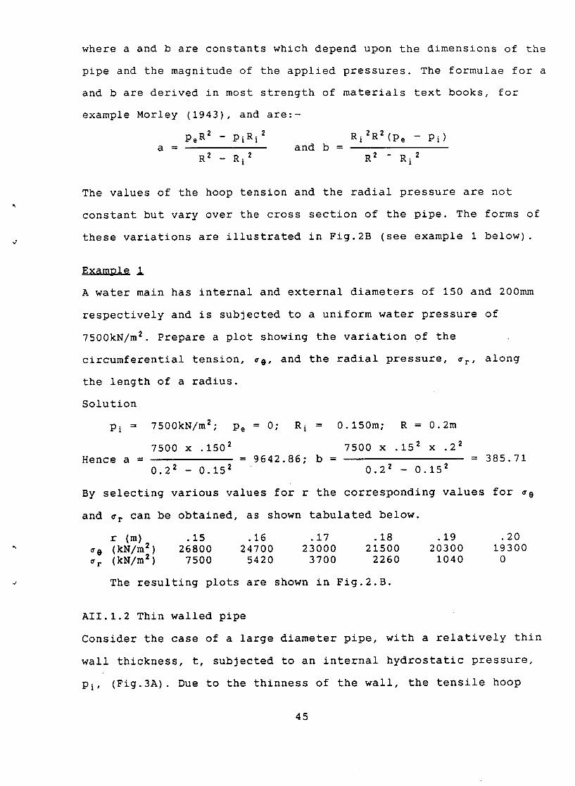
where a and b are constants which depend upon the dimensions of the
pipe and the magnitude of the applied pressures. The formulae for a
and b are derived in most strength of materials text books, for
example Morley (1943), and are:-
Pe R2 - PiRi 2 Ri2R2(pe - Pi)
a = and b = R 2 _ Ri 2 R 2 - Ri 2
The values of the hoop tension and the radial pressure are not
constant but vary over the cross section of the pipe. The forms of
these variations are illustrated in Fig.2B (see example i below).
ExamPle !
A water main has internal and external diameters of 150 and 200mm
respectively and is subjected to a uniform water pressure of
7500kN/m 2. Prepare a plot showing the variation of the
circumferential tension, ce, and the radial pressure, ~r, along
the length of a radius.
Solution
Pi = 7500kN/m2", Pe = 0;
Hence a = 7500 x .1502
0.22 - 0.152
R i = 0.150m; R = 0.2m
7500 x .152 x .22 = 9642.86; b =
0.22 - 0.152 = 385.71
By selecting various values for r the corresponding values for ~e
and cr can be obtained, as shown tabulated below.
r (m) .15 .16 .17 .18 .19 .20 ~e (kN/m2) 26800 24700 23000 21500 20300 19300 ~r (kN/m2) 7500 5420 3700 2260 1040 0
The resulting plots are shown in Fig.2.B.
AII.I.2 Thin walled pipe
Consider the case of a large diameter pipe, with a relatively thin
wall thickness, t, subjected to an internal hydrostatic pressure,
Pi, (Fig.3A). Due to the thinness of the wall, the tensile hoop
45
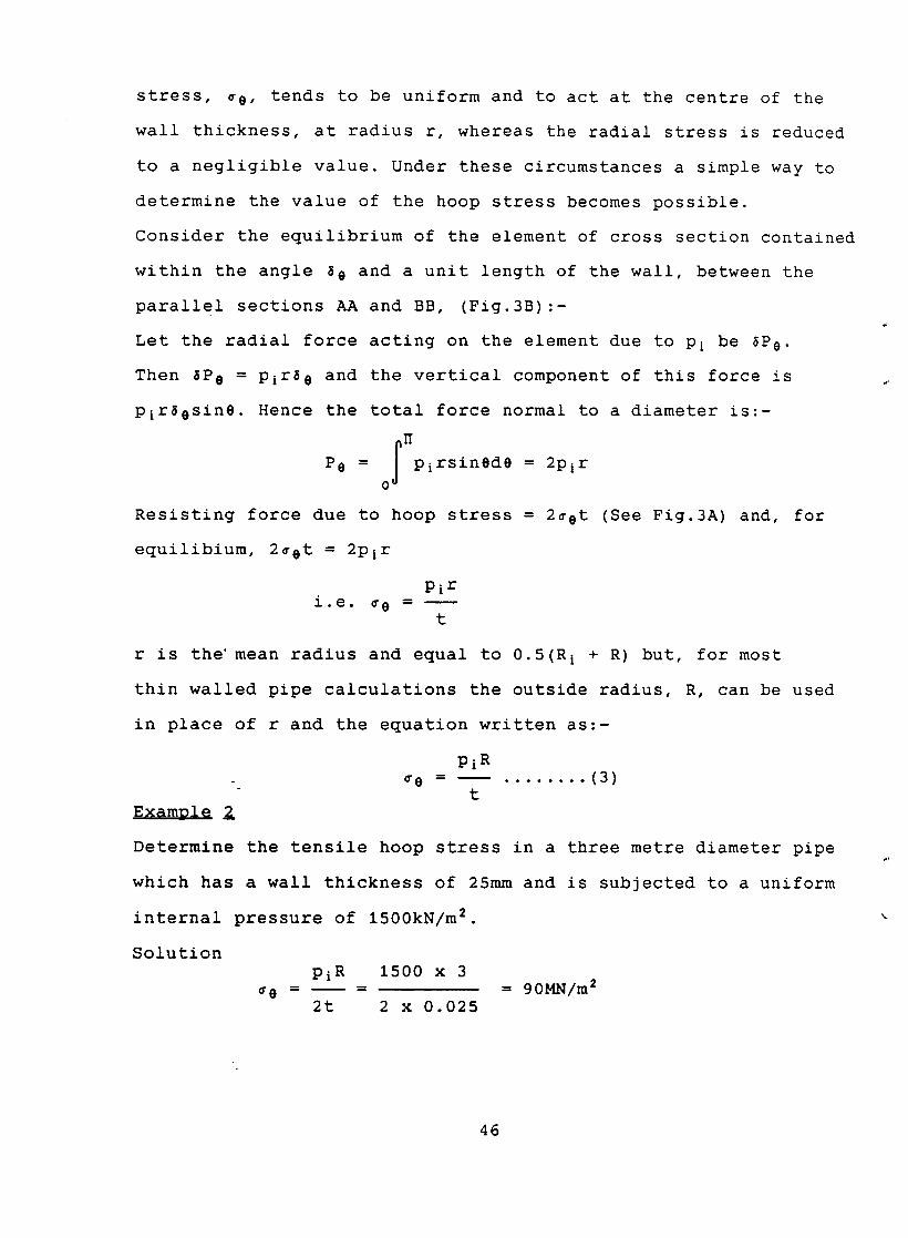
stress, ~e, tends to be uniform and to act at the centre of the
wall thickness, at radius r, whereas the radial stress is reduced
to a negligible value. Under these circumstances a simple way to
determine the value of the hoop stress becomes possible.
Consider the equilibrium of the element of cross section contained
within the angle 80 and a unit length of the wall, between the
parallel sections AA and BB, (Fig.3B):-
Let the radial force acting on the element due to Pi be ~P0-
Then 8Pc = Pir~e and the vertical component of this force is
Pir~esine. Hence the total force normal to a diameter is:-
O P0 = I Pirsined0 = 2Pir
o 0
Resisting force due to hoop stress = 2¢et (See Fig.3A) and, for
equilibium, 2cet = 2Pir
i.e. ~e Pi r
t
r is the' mean radius and equal to 0.5(R i + R) but, for most
thin walled pipe calculations the outside radius, R, can be used
in place of r and the equation written as:-
Pi R = . . . . . . . . (3)
t
Determine the tensile hoop stress in a three metre diameter pipe
which has a wall thickness of 25mm and is subjected to a uniform
internal pressure of 1500kN/m 2.
Solution pi R 1500 x 3
~e - =
2t 2 x 0.025 = 90MN/m 2
46
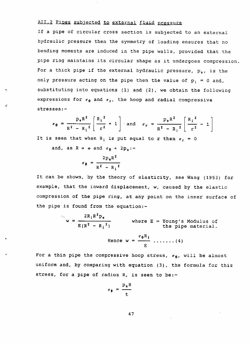
AII,2 PiDes subjected to ~ fluid
If a pipe of circular cross section is subjected to an external
hydraulic pressure then the symmetry of loading ensures that no
bending moments are induced in the pipe walls, provided that the
pipe ring maintains its circular shape as it undergoes compression.
For a thick pipe if the external hydraulic pressure, Pe, is the
only pressure acting on the pipe then the value of Pi = 0 and,
substituting into equations (I) and (2), we obtain the following
expressions for Ce and Cr, the hoop and radial compressive
stresses:-
[ i2 I Pe 2 [ i2 1 - + 1 and ¢r = 1 cTe 2 2 R2 2 r 2 R 2 - R i r - R i
It is seen that when R i is put equal to r then Cr = 0
and, as R ~ m and ¢8 ~ 2Pe:-
2Pe R2
Ce -- R 2 _ Ri 2
It can be shown, by the theory of elasticity, see Wang (1953) for
example, that the inward displacement , w, caused by the elastic
compression of the pipe ring, at any point on the inner surface of
the pipe is found from the equation:-
W =
2RiR2pe
E(R 2 - Ri 2 ) where E = Young's Modulus of
the pipe material.
Hence w - ~eRi
E ....... (4)
For a thin pipe the compressive hoop stress, ~e, will be almost
uniform and, by comparing with equation (3), the formula for this
stress, for a pipe of radius R, is seen to be:-
Pe R
Ge - t
47
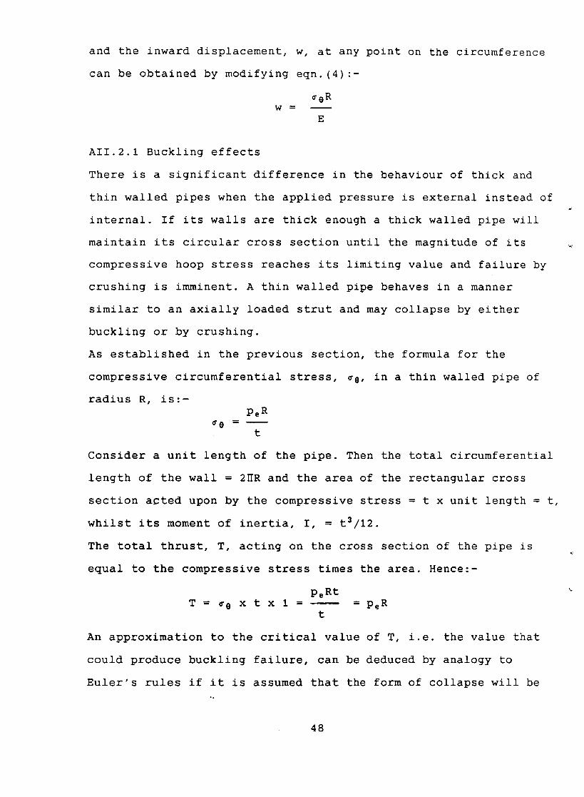
and the inward displacement, w, at any point on the circumference
can be obtained by modifying eqn.(4):-
~0R w =
E
AII.2.1 Buckling effects
There is a significant difference in the behaviour of thick and
thin walled pipes when the applied pressure is external instead of
internal. If its walls are thick enough a thick walled pipe will
maintain its circular cross section until the magnitude of its
compressive hoop stress reaches its limiting value and failure by
crushing is imminent. A thin walled pipe behaves in a manner
similar to an axially loaded strut and may collapse by either
buckling or by crushing.
As established in the previous section, the formula for the
compressive circumferential stress, ~e, in a thin walled pipe of
radius R, is:-
Pe R ~e -
t
Consider a unit length of the pipe. Then the total circumferential
length of the wall = 2~R and the area of the rectangular cross
section acted upon by the compressive stress = t x unit length = t,
whilst its moment of inertia, I, = ts/12.
The total thrust, T, acting on the cross section of the pipe is
equal to the compressive stress times the area. Hence:-
PeRt T = ce x t x 1 = = pe R
t
An approximation to the critical value of T, i.e. the value that
could produce buckling failure, can be deduced by analogy to
Euler's rules if it is assumed that the form of collapse will be -o
48
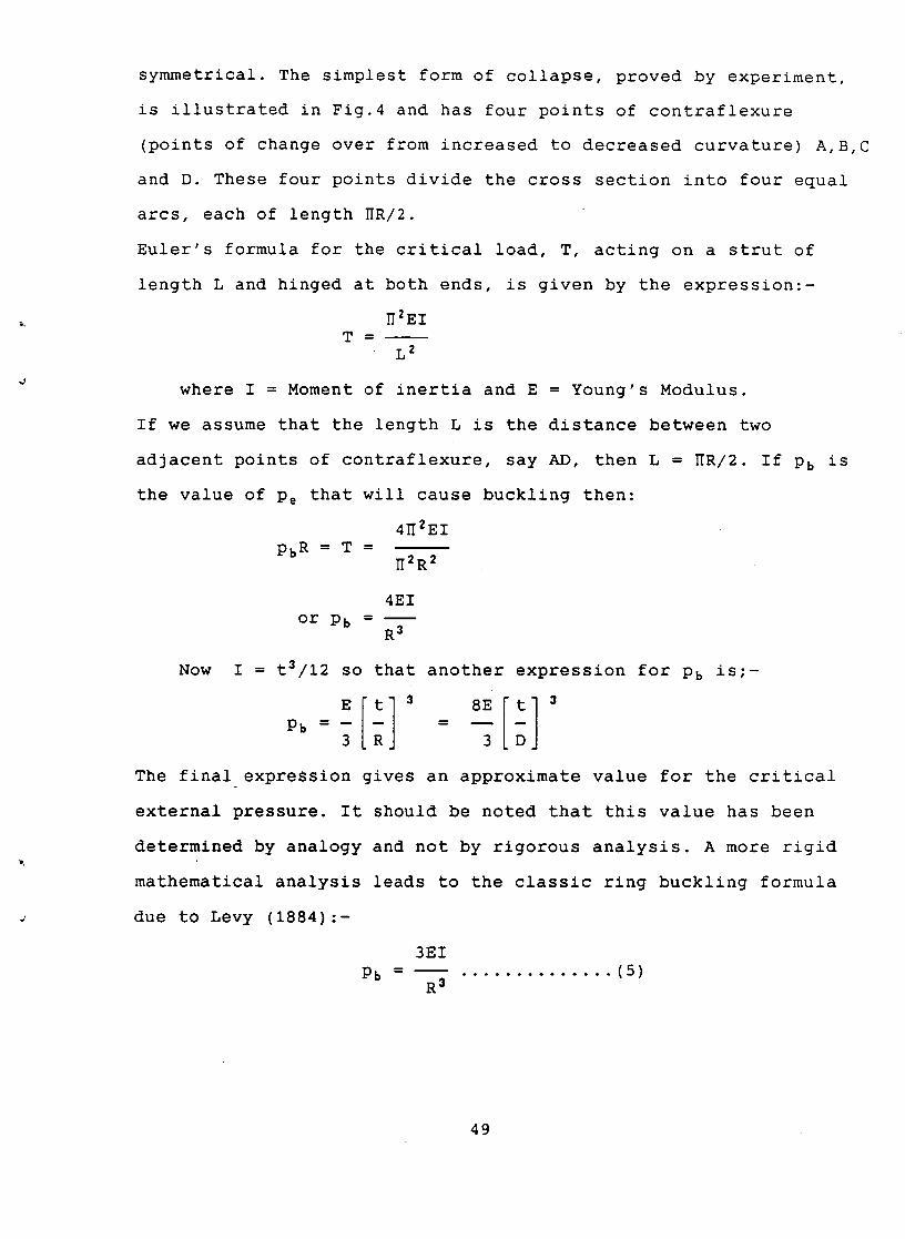
symmetrical. The simplest form of collapse, proved by experiment,
is illustrated in Fig.4 and has four points of contraflexure
(points of change over from increased to decreased curvature) A,B,C
and D. These four points divide the cross section into four equal
arcs, each of length ~R/2.
Euler's formula for the critical load, T, acting on a strut of
length L and hinged at both ends, is given by the expression:-
~2EI T -
L 2
where I = Moment of inertia and E = Young's Modulus.
If we assume that the length L is the distance between two
adjacent points of contraflexure, say AD, then L = ~R/2. If Pb is
the value of Pe that will cause buckling then:
4~2EI pbR = T =
~2R2
4 E I or Pb -
R 3
Now I = t3/12 so that another expression for Pb is;--
P b ~ . . . . .
3 R 3 D
The final expression glves an approximate value for the critical
external pressure. It should be noted that this value has been
determined by analogy and not by rigorous analysis. A more rigid
mathematical analysis leads to the classic ring buckling formula
due to Levy (1884):-
3EI
Pb - R 3
. . . . . . . . . . . . . . ( 5 )
49
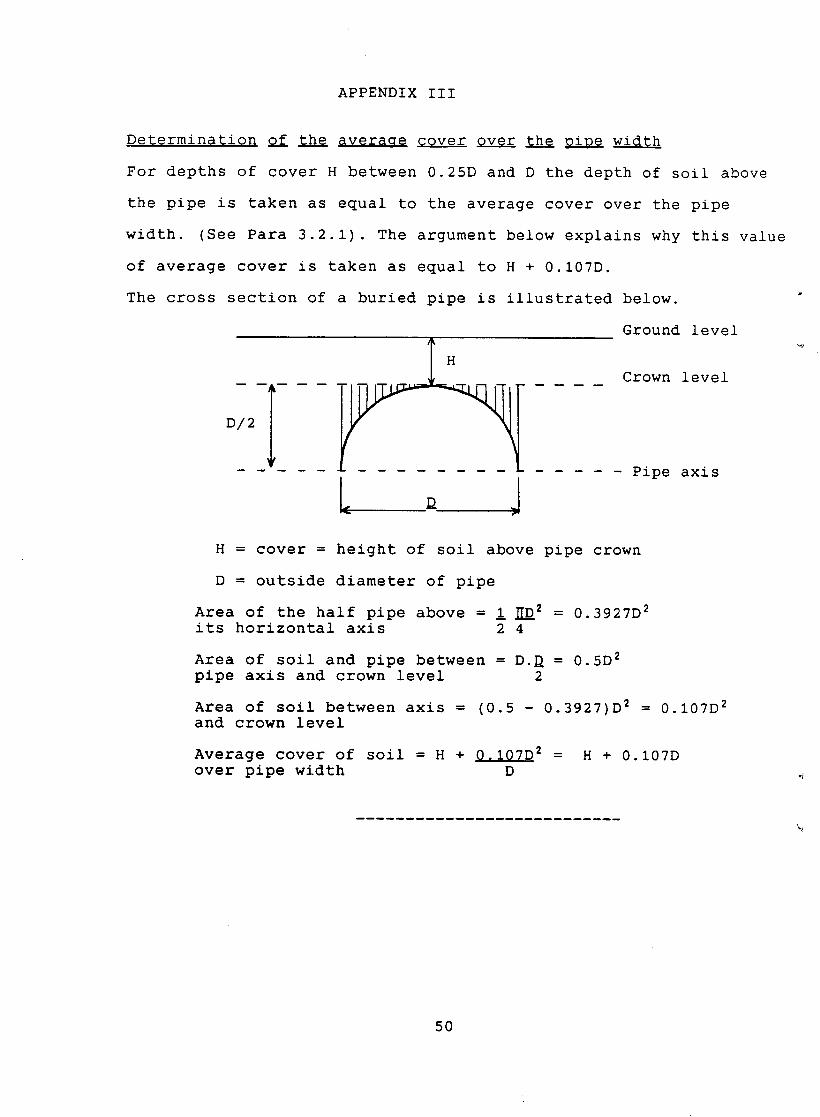
APPENDIX III
Determination Qf ~h~ averaae GQver Qv~r ~h@ pipQ width
For depths of cover H between 0.25D and D the depth of soil above
the pipe is taken as equal to the average cover over the pipe
width. (See Para 3.2.1). The argument below explains why this value
of average cover is taken as equal to H + 0.107D.
The cross section of a buried pipe is illustrated below.
D/2
H
I L D
Ground level
Crown level
Pipe axis
H = cover = height of soil above pipe crown
D = outside diameter of pipe
Area of the half pipe above = ! ~D 2 = 0.3927D 2 its horizontal axis 2 4
Area of soil and pipe between = D.D = 0.5D 2 pipe axis and crown level 2
Area of soil between axis = (0.5 - 0.3927)D 2 = 0.107D 2 and crown level
Average cover of soil = H + 0.107D 2 = H + 0.107D over pipe width D
50

J
FIGURES
51
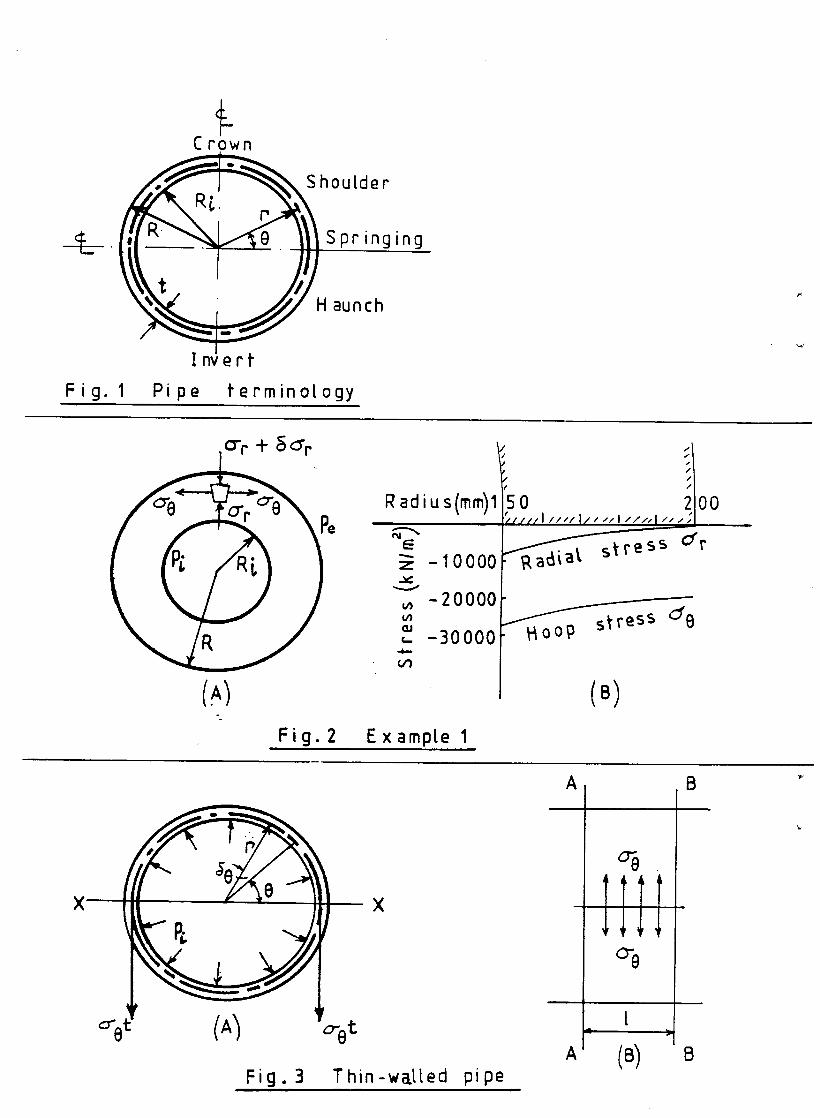
Crown
h0u lde r
-t-- Springing
i aunch
g. Pipe Fi ferminotogy
(_A/ - °
0",, + ~ ~
R adiu s(mm)l
E - 10000
~, -20000 u~
,- -30000 .,¢..
or)
Fig . 2 Examp[e 1
1 '5 0 O0 ( f i l l I l / , I I1" , . I / I / ' 1 / ' "
~ t st ress d r
d e HooI~ stress
(8)
X
e~ (A) o-et
Fig. 3 Thin-walLed pipe
A B
A
%
u
[
IB) 8
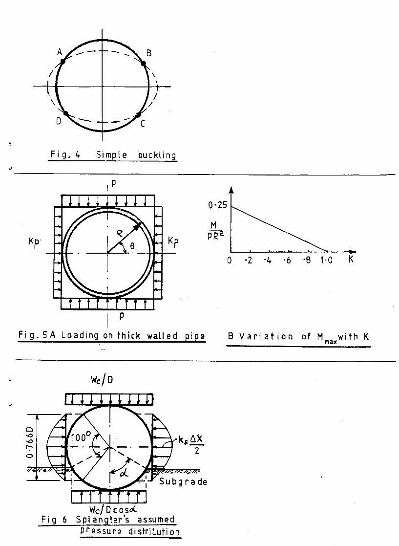
A
'\~ I h /
o " ~ -+- - - .7-c
.,,,t
Kp~
Fig. /. Simpte buck[ing
P I
0"25
p•P- Kp 0 • 2 "4 .6 "8 1-0 K
F ig . SA
I P
Loading on thick watled pipe B V a r i a f i o n of M max
with K
Fig 6 Wc/D c osd,.
'S Sp[angler assumed pressure distribufi on
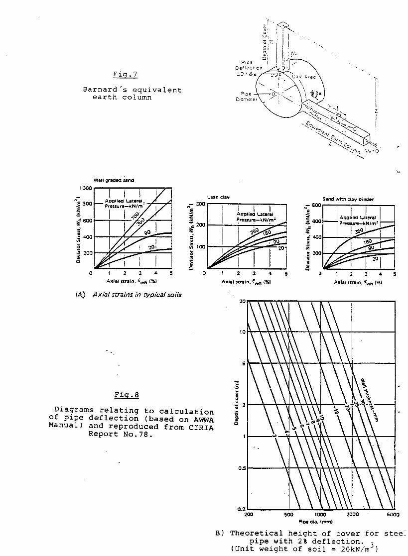
Fig.7
Barnard's equivalent earth column
o : I I " -
~..i ~ " ' , ,
"<~ ,'~.' 0
Well gr~leQ ~ n d
'=°1 i i l / / __ | AolSlie~l Lateral. / I A Lean claw Sand with clay bin(~er
a ~ . I - - P ~ , , , . , a - ~ N ' m ' 2 q 7 - 1 - zoo . " I I I ~ / E i , ~ z ' . / l ~ I .°o,,.,.,-, 1 3 '°°1 = J I I
---- ~"~' [ - - ' ~ " Pressunl--kN/m: 200 ' : ' ooo %!!
0 I 2 3 4 5 0 1 2 3 4 5 0 1 2 3 4
Axial strain. ~,,,.n (%} Axial strain, ewn (%| Axiai s1~i. , ~wn (%)
(,4.) A x i a l s t ra ins in t y p i c a l soi ls .- 2 0
O
- 2 O "S
°
Fig.8
Diagrams relating to calculation of pipe deflection (based on AWWA Manual) and reproduced from CIRIA
Report No.78.
10
0.5
0.2. 2 0 0 5 0 0 1 0 0 0 2 0 0 0 5 0 0 0
P~I dia. (ram)
B) Theoretical height of cover for stee: pipe with 2% deflection.
(Unit w e i g h t o f s o i l = 20kN/m ~)
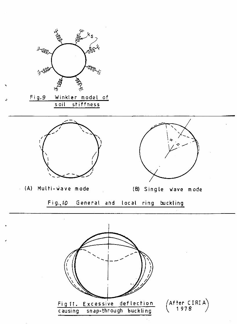
"- ks
Fig,9 Winkter mode[ soit s t i f fness
of i
f ~
/ \
(A) Mu[ti-v~ave mode (B) Single ,dave mode
Fig_.fO Genera[ and local ring buckling i
I m
J
Fig l t . Excessive d e f l e c t i o n causing snap-through • buck[i ng
i
After £ I R! A) 1978
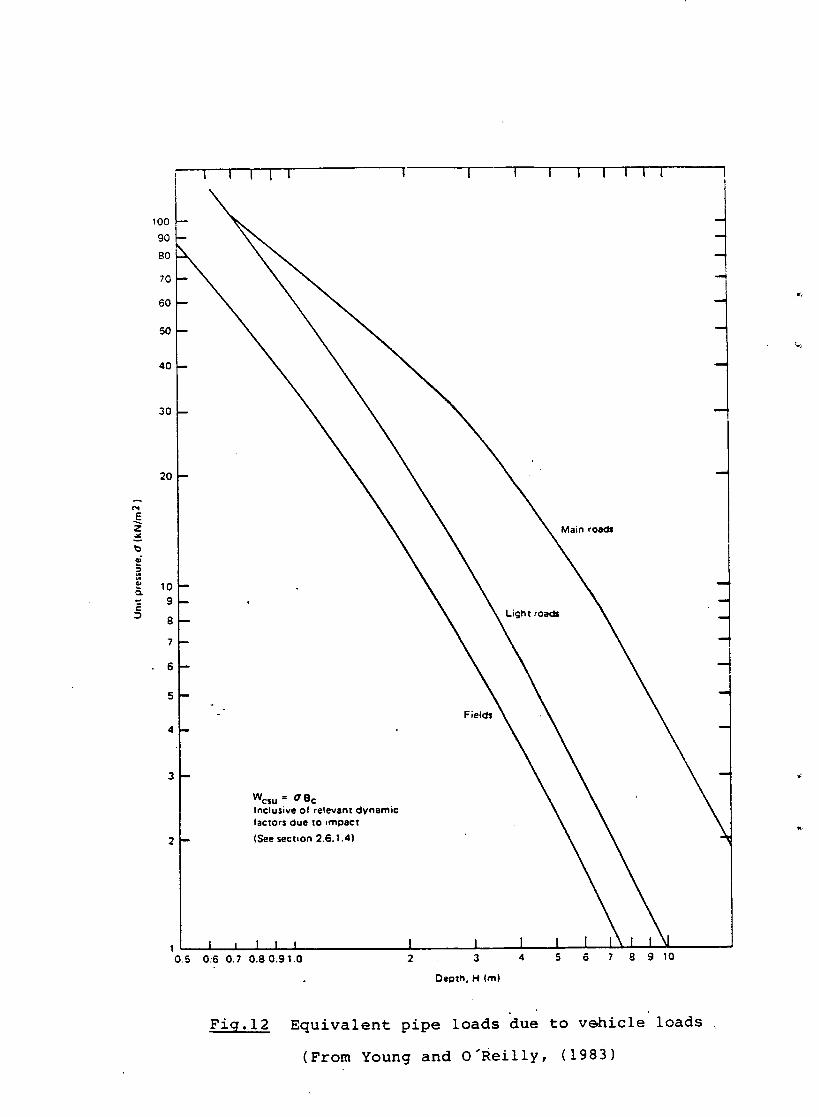
Z
t , -
D
I
100
9O
7 0
6O
5 0 - -
40
30
20
10 9
8
i t I I I
-
Fields
I I I
Main roads
Light roa~i
I I I i
m
!
!
m
Wc$ u = (7 B c Inclusive of relevant dynamic faclors due to ~mpact
(See sect,on 2.6.1.4)
I I | I | I I
0.5 0.6 0.7 0.80.91.0 I I 2 3
Depth, H (m|
4 5 6 7 8 9 10
Fig.12 Equivalent pipe loads "due to v~nicle" loads
(From Young and o'Reilly, (1983)