Embed Size (px)
Citation preview
Health and Safety Executive
Assessment of fire and explosionrisks in coating mixing operations
Prepared by the Health and Safety Laboratory for the Health and Safety Executive 2007
RR526 Research Report
Health and Safety Executive
Assessment of fire and explosionrisks in coating mixing operations
Mr D Hedley B Eng, Dr D K Pritchard & Mr G T Eaton Health and Safety Laboratory Harpur Hill Buxton Derbyshire SK17 9JN
The Dangerous Substances and Explosive Atmospheres Regulations 2002 (DSEAR) necessitate a re-assessment of the fire and explosion risks arising from the formation of explosive atmospheres in and around coatings mixing vessels. A programme of work has been commissioned by HSE to review the hazards that would need to be covered by the risk assessment and to carry out experimental work to fill in any gaps in knowledge. The outcome of the project would be used to inform the development of HSE’s DSEAR Enforcement Policy on coatings mixing operations. This report presents the findings of Phase 2 of the project, the objectives of which were to:
n Undertake site visits to make vapour concentration measurements in and around coatings mixing vessels.
n Perform ignition tests on example coatings at HSL.
This report and the work it describes were funded by the Health and Safety Executive (HSE). Its contents, including any opinions and/or conclusions expressed, are those of the authors alone and do not necessarily reflect HSE policy.
HSE Books
© Crown copyright 2007
First published 2007
All rights reserved. No part of this publication may bereproduced, stored in a retrieval system, or transmitted inany form or by any means (electronic, mechanical,photocopying, recording or otherwise) without the priorwritten permission of the copyright owner.
Applications for reproduction should be made in writing to:Licensing Division, Her Majesty’s Stationery Office,St Clements House, 2-16 Colegate, Norwich NR3 1BQor by e-mail to [email protected]
Acknowledgements:
Leigh’s Paints Ltd, Bolton International Paints Ltd, Felling, Gateshead PPG Industries (UK) Ltd, Stowmarket Sun Chemical Ltd, Watford British Coatings Federation, Leatherhead
ii
CONTENTS
1 INTRODUCTION......................................................................................... 1
2 EXPERIMENTAL PROGRAMME.................................................................2 2.1 Site visits ..................................................................................................2 2.2 Ignition tests .............................................................................................4
3 RESULTS.....................................................................................................7 3.1 Site Visits..................................................................................................7 3.2 Ignition tests .......................................................................................... 12
4 DISCUSSION............................................................................................ 154.1 Site Visits............................................................................................... 154.2 Ignition tests .......................................................................................... 16 4.3 Further work .......................................................................................... 16
5 CONCLUSIONS.........................................................................................16
6 REFERENCES...........................................................................................17
7 GLOSSARY ...............................................................................................18
8 APPENDIX A – RISK ASSESSMENT....................................................... 21
iii

iv

EXECUTIVE SUMMARY
Objectives The Dangerous Substances and Explosive Atmospheres Regulations 2002 (DSEAR) necessitate a re-assessment of the fire and explosion risks arising from the formation of explosive atmospheres in and around coatings mixing vessels. A programme of work has been commissioned by HSE to review the hazards that would need to be covered by the risk assessment and to carry out experimental work to fill in any gaps in knowledge. The outcome of the project would be used to inform the development of HSE’s DSEAR Enforcement Policy on coatings mixing operations. This report presents the findings of Phase 2 of the project, the objectives of which were to:
• Undertake site visits to make vapour concentration measurements in and around coatings mixing vessels.
• Perform ignition tests on example coatings at HSL.
Main Findings
1) Five site visits, to two paint manufacturers and one ink manufacturer, have been undertaken to measure the vapour concentrations in and around mixing units. An explosive mixture, i.e., above 100% LEL, of vapour and air was found inside the mixing vessel at the ink manufacturer (ethanol/ethyl acetate based ink). Non-explosive mixtures of vapour and air in the % LEL range were found inside the mixing vessels at the paint manufacturers (xylene based paints). The results confirmed that the important parameters in the formation of an explosive atmosphere are as follows:
a. The volatility of the solvents. b. The ventilation rate. c. The temperature of the mixture. d. The proportions of solvents and resins in the mixture.
2) Mixtures based on solvents with lower volatilities than those studied in the site visits would be expected to generate non-explosive mixtures in the mixing vessel. No site measurements have been undertaken to confirm this conclusion.
3) Manual addition of solvents during mixing, especially in the latter stages of the mixing process when the mixture is warm, can generate high transient vapour concentrations in the mixing vessel.
4) Ignition tests, using an experimental rig representative of small batch operations using open vessels or vessels with loose fitting lids, have been undertaken. Ink (ethanol/ethyl acetate based) and paint mixtures (xylene based) were mixed to give temperatures similar to those found on the site visits. On igniting the vapour generated in the mixing vessel an explosion and fire occurred with all three ink tests. A small flash occurred during one of the paint tests. There was no liquid ejected from the vessel during any of the tests.
v
Recommendations
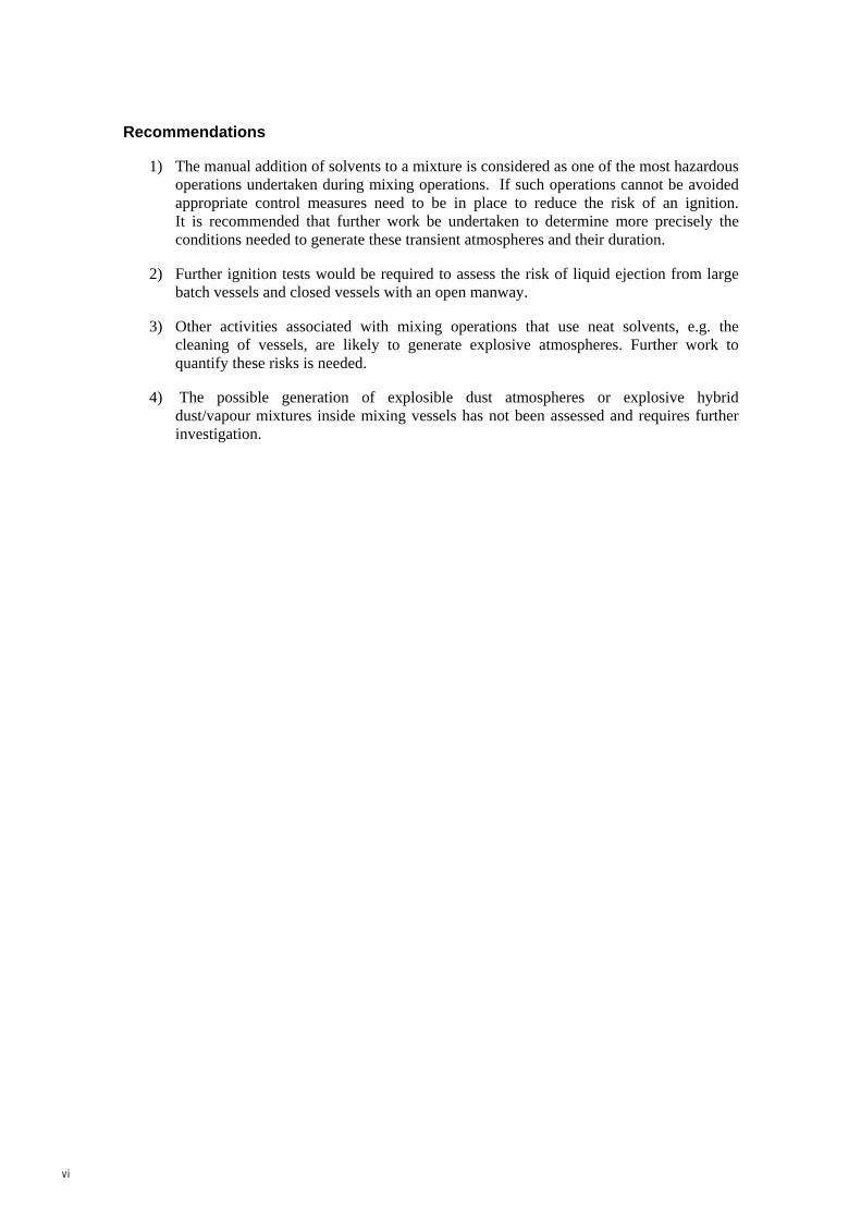
1) The manual addition of solvents to a mixture is considered as one of the most hazardous operations undertaken during mixing operations. If such operations cannot be avoided appropriate control measures need to be in place to reduce the risk of an ignition. It is recommended that further work be undertaken to determine more precisely the conditions needed to generate these transient atmospheres and their duration.
2) Further ignition tests would be required to assess the risk of liquid ejection from large batch vessels and closed vessels with an open manway.
3) Other activities associated with mixing operations that use neat solvents, e.g. the cleaning of vessels, are likely to generate explosive atmospheres. Further work to quantify these risks is needed.
4) The possible generation of explosible dust atmospheres or explosive hybrid dust/vapour mixtures inside mixing vessels has not been assessed and requires further investigation.
vi
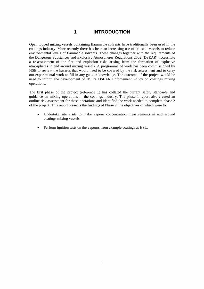
1 INTRODUCTION
Open topped mixing vessels containing flammable solvents have traditionally been used in the coatings industry. More recently there has been an increasing use of ‘closed’ vessels to reduce environmental levels of flammable solvents. These changes together with the requirements of the Dangerous Substances and Explosive Atmospheres Regulations 2002 (DSEAR) necessitate a re-assessment of the fire and explosion risks arising from the formation of explosive atmospheres in and around mixing vessels. A programme of work has been commissioned by HSE to review the hazards that would need to be covered by the risk assessment and to carry out experimental work to fill in any gaps in knowledge. The outcome of the project would be used to inform the development of HSE’s DSEAR Enforcement Policy on coatings mixing operations. The first phase of the project (reference 1) has collated the current safety standards and guidance on mixing operations in the coatings industry. The phase 1 report also created an outline risk assessment for these operations and identified the work needed to complete phase 2 of the project. This report presents the findings of Phase 2, the objectives of which were to:
• Undertake site visits to make vapour concentration measurements in and around coatings mixing vessels.
• Perform ignition tests on the vapours from example coatings at HSL.
1
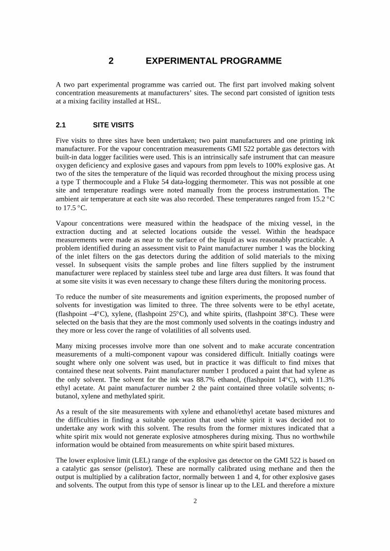
2 EXPERIMENTAL PROGRAMME
A two part experimental programme was carried out. The first part involved making solvent concentration measurements at manufacturers’ sites. The second part consisted of ignition tests at a mixing facility installed at HSL.
2.1 SITE VISITS
Five visits to three sites have been undertaken; two paint manufacturers and one printing ink manufacturer. For the vapour concentration measurements GMI 522 portable gas detectors with built-in data logger facilities were used. This is an intrinsically safe instrument that can measure oxygen deficiency and explosive gases and vapours from ppm levels to 100% explosive gas. At two of the sites the temperature of the liquid was recorded throughout the mixing process using a type T thermocouple and a Fluke 54 data-logging thermometer. This was not possible at one site and temperature readings were noted manually from the process instrumentation. The ambient air temperature at each site was also recorded. These temperatures ranged from 15.2 °C to 17.5 °C.
Vapour concentrations were measured within the headspace of the mixing vessel, in the extraction ducting and at selected locations outside the vessel. Within the headspace measurements were made as near to the surface of the liquid as was reasonably practicable. A problem identified during an assessment visit to Paint manufacturer number 1 was the blocking of the inlet filters on the gas detectors during the addition of solid materials to the mixing vessel. In subsequent visits the sample probes and line filters supplied by the instrument manufacturer were replaced by stainless steel tube and large area dust filters. It was found that at some site visits it was even necessary to change these filters during the monitoring process.
To reduce the number of site measurements and ignition experiments, the proposed number of solvents for investigation was limited to three. The three solvents were to be ethyl acetate, (flashpoint –4°C), xylene, (flashpoint 25°C), and white spirits, (flashpoint 38°C). These were selected on the basis that they are the most commonly used solvents in the coatings industry and they more or less cover the range of volatilities of all solvents used.
Many mixing processes involve more than one solvent and to make accurate concentration measurements of a multi-component vapour was considered difficult. Initially coatings were sought where only one solvent was used, but in practice it was difficult to find mixes that contained these neat solvents. Paint manufacturer number 1 produced a paint that had xylene as the only solvent. The solvent for the ink was 88.7% ethanol, (flashpoint 14°C), with 11.3% ethyl acetate. At paint manufacturer number 2 the paint contained three volatile solvents; n-butanol, xylene and methylated spirit.
As a result of the site measurements with xylene and ethanol/ethyl acetate based mixtures and the difficulties in finding a suitable operation that used white spirit it was decided not to undertake any work with this solvent. The results from the former mixtures indicated that a white spirit mix would not generate explosive atmospheres during mixing. Thus no worthwhile information would be obtained from measurements on white spirit based mixtures.
The lower explosive limit (LEL) range of the explosive gas detector on the GMI 522 is based on a catalytic gas sensor (pelistor). These are normally calibrated using methane and then the output is multiplied by a calibration factor, normally between 1 and 4, for other explosive gases and solvents. The output from this type of sensor is linear up to the LEL and therefore a mixture
2
of solvent vapours can be measured accurately providing the ratio of solvent vapours is known. The ratio of liquid solvents cannot be used because the vapour pressure curves (volatility) of the solvents will not be equal. Using the largest calibration factor from the solvents present will always provide an “indication of safety”. In this way all readings taken will be larger than the actual reading and a worst case value is always achieved (see results below).
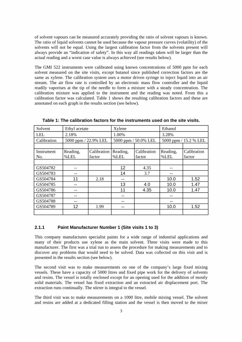
The GMI 522 instruments were calibrated using known concentrations of 5000 ppm for each solvent measured on the site visits, except butanol since published correction factors are the same as xylene. The calibration system uses a motor driven syringe to inject liquid into an air stream. The air flow rate is controlled by an electronic mass flow controller and the liquid readily vaporises at the tip of the needle to form a mixture with a steady concentration. The calibration mixture was applied to the instrument and the reading was noted. From this a calibration factor was calculated. Table 1 shows the resulting calibration factors and these are annotated on each graph in the results section (see below).
Table 1: The calibration factors for the instruments used on the site visits.
Solvent Ethyl acetate Xylene Ethanol LEL 2.18% 1.00% 3.28% Calibration 5000 ppm / 22.9% LEL 5000 ppm / 50.0% LEL 5000 ppm / 15.2 % LEL Instrument No.
Reading, %LEL
Calibration factor
Reading, %LEL
Calibration factor
Reading, %LEL
Calibration factor
GS504782 -- 12 4.35 -- GS504783 -- 14 3.7 -- GS504784 11 2.18 -- 10.0 1.52 GS504785 -- 13 4.0 10.0 1.47 GS504786 -- 11 4.35 10.0 1.47 GS504787 -- -- -- GS504788 -- -- -- GS504789 12 1.99 -- 10.0 1.52
2.1.1 Paint Manufacturer Number 1 (Site visits 1 to 3)
This company manufactures specialist paints for a wide range of industrial applications and many of their products use xylene as the main solvent. Three visits were made to this manufacturer. The first was a trial run to assess the procedure for making measurements and to discover any problems that would need to be solved. Data was collected on this visit and is presented in the results section (see below).
The second visit was to make measurements on one of the company’s large fixed mixing vessels. These have a capacity of 5000 litres and fixed pipe work for the delivery of solvents and resins. The vessel is totally enclosed except for an opening used for the addition of mostly solid materials. The vessel has fixed extraction and an extracted air displacement port. The extraction runs continually. The stirrer is integral to the vessel.
The third visit was to make measurements on a 1000 litre, mobile mixing vessel. The solvent and resins are added at a dedicated filling station and the vessel is then moved to the mixer
3

where the solids are added. The lid for the mobile vessel is attached to the mixer and is moved up and down hydraulically with the stirrer. The lid incorporates an extraction duct, a powder chute for 1 tonne bags and a wide opening for manually handled bags. The extraction runs continually. The mixing process examined on this visit required the paint to reach a minimum temperature of 55°C.
2.1.2 Ink Manufacturer (Site visit 5)
This company manufactures printing inks, mainly for newspapers, other publications, packaging and other commercial usage. The visit was to make measurements on a mobile mixing vessel with a capacity of 900 litres. The solvents and resin are added to the vessel at a filling station and it is then moved to a mixer where the solids are added. The circular lid for the mobile vessel is attached to the mixer and includes an extraction duct and a hinged segment lid that opens for filling from manually handled bags. The local exhaust ventilation (LEV) had a manually operated damper that the operator opened when he started to add the solid material and closed when he closed the filling lid. In this case the extraction is designed to protect the operator from occupational exposure levels of solvent.
2.1.3 Paint Manufacturer Number 2 (Site visit 4)
This company manufactures paints for a wide range of applications in the marine environment. The visit was to make measurements on one of the company’s large fixed mixing vessels. These have a capacity of 5000 litres and fixed pipe work for the delivery of solvents and resins. The stirrer is integral to the vessel. The vessel is totally enclosed except for an opening used for the addition of materials. It has fixed extraction and the lid to the main opening is linked to a damper on the extraction ductwork. The damper opens when the filling lid is lifted, i.e., the extraction is designed to protect the operator from occupational exposure levels of solvent.
2.2 IGNITION TESTS
Ignition experiments were carried out in which attempts were made to deliberately ignite the vapour in the vessel headspace. The trials were videoed to record visually what happened when an ignition occurred. The tests were carried out with headspace vapours similar to those investigated during the site visits. The mixtures were heated, by stirring, to temperatures similar to those measured, on the equivalent mixes, during the site visits. For each test the mixing vessel was filled approximately 55% full.
To reduce the number of experiments, the number of solvents was limited to the two most volatile. These were xylene (flashpoint 25°C) and an ethyl acetate/ethanol mixture, (flashpoints -4°C and 14°C respectively). Coatings containing the solvents were supplied to HSL by the coatings industry through the British Coatings Federation (BCF). The first was an epoxy paint base with xylene as the only solvent. The second was an ink with a solvent that was 90.9% to 71.4% ethanol with 9.1% to 28.6% ethyl acetate.. The coatings were poured into the vessel and then stirred until they reached the temperature required for the test. Ambient temperatures at the test site were low and the mixing vessel had to be lagged so that the coatings would achieve and maintain the required temperature. Four inches of glass fibre cavity wall insulation was used on the sides and top of the vessel. Once the temperature was reached, the heat loss was minimal even when left overnight. The insulation on the vessel lid was removed before each ignition test. 4
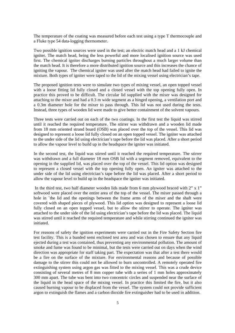
The temperature of the coating was measured before each test using a type T thermocouple and a Fluke type 54 data-logging thermometer.
Two possible ignition sources were used in the test; an electric match head and a 1 kJ chemical igniter. The match head, being the less powerful and more localised ignition source was used first. The chemical igniter discharges burning particles throughout a much larger volume than the match head. It is therefore a more distributed ignition source and this increases the chance of igniting the vapour. The chemical igniter was used after the match head had failed to ignite the mixture. Both types of igniter were taped to the lid of the mixing vessel using electrician’s tape.
The proposed ignition tests were to simulate two types of mixing vessel, an open topped vessel with a loose fitting lid fully closed and a closed vessel with the top opening fully open. In practice this proved to be difficult. The circular lid supplied with the mixer was designed for attaching to the mixer and had a 0.3 m wide segment as a hinged opening, a ventilation port and a 0.3m diameter hole for the mixer to pass through. This lid was not used during the tests. Instead, three types of wooden lid were made to give better containment of the solvent vapours.
Three tests were carried out on each of the two coatings. In the first test the liquid was stirred until it reached the required temperature. The stirrer was withdrawn and a wooden lid made from 18 mm oriented strand board (OSB) was placed over the top of the vessel. This lid was designed to represent a loose lid fully closed on an open topped vessel. The igniter was attached to the under side of the lid using electrician’s tape before the lid was placed. After a short period to allow the vapour level to build up in the headspace the igniter was initiated.
In the second test, the liquid was stirred until it reached the required temperature. The stirrer was withdrawn and a full diameter 18 mm OSB lid with a segment removed, equivalent to the opening in the supplied lid, was placed over the top of the vessel. This lid option was designed to represent a closed vessel with the top opening fully open. An igniter was attached to the under side of the lid using electrician’s tape before the lid was placed. After a short period to allow the vapour level to build up in the headspace the igniter was initiated.
In the third test, two half diameter wooden lids made from 6 mm plywood braced with 2” x 1” softwood were placed over the entire area of the top of the vessel. The mixer passed through a hole in `the lid and the openings between the frame arms of the mixer and the shaft were covered with shaped pieces of plywood. This lid option was designed to represent a loose lid fully closed on an open topped vessel, but to allow the stirrer to operate. The igniter was attached to the under side of the lid using electrician’s tape before the lid was placed. The liquid was stirred until it reached the required temperature and while stirring continued the igniter was initiated.
For reasons of safety the ignition experiments were carried out in the Fire Safety Section fire test facility. This is a bunded semi enclosed test area and was chosen to ensure that any liquid ejected during a test was contained, thus preventing any environmental pollution. The amount of smoke and fume was found to be minimal, but the tests were carried out on days when the wind direction was appropriate for staff taking part. The expectation was that after a test there would be a fire on the surface of the mixture. For environmental reasons and because of possible damage to the stirrer this could not be allowed to burn uncontrolled. A remotely operated fire extinguishing system using argon gas was fitted to the mixing vessel. This was a crude device consisting of several metres of 8 mm copper tube with a series of 1 mm holes approximately 300 mm apart. The tube was bent into two concentric circles and suspended near the surface of the liquid in the head space of the mixing vessel. In practice this limited the fire, but it also caused burning vapour to be displaced from the vessel. The system could not provide sufficient argon to extinguish the flames and a carbon dioxide fire extinguisher had to be used in addition.
5

The mixing vessel and stirrer were supplied to HSL by the coatings industry through BCF. The stirrer was a Silverson GX10 mixer with an 11kW motor, general purpose disintegrating head and a down thrust propeller 100 mm above the mixing head. The pans were 1.125m diameter and 0.89 m deep at the outer edge giving an approximate volume of 885 litres.
6
3 RESULTS
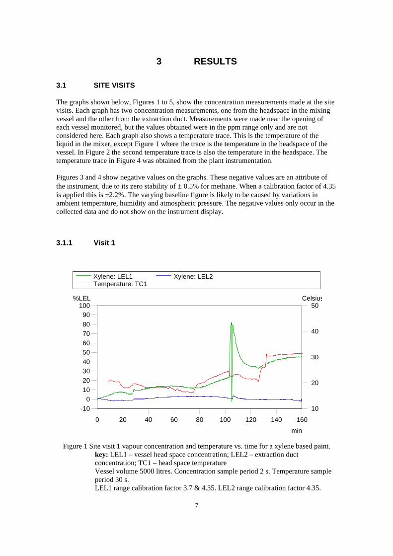
3.1 SITE VISITS The graphs shown below, Figures 1 to 5, show the concentration measurements made at the site visits. Each graph has two concentration measurements, one from the headspace in the mixing vessel and the other from the extraction duct. Measurements were made near the opening of each vessel monitored, but the values obtained were in the ppm range only and are not considered here. Each graph also shows a temperature trace. This is the temperature of the liquid in the mixer, except Figure 1 where the trace is the temperature in the headspace of the vessel. In Figure 2 the second temperature trace is also the temperature in the headspace. The temperature trace in Figure 4 was obtained from the plant instrumentation. Figures 3 and 4 show negative values on the graphs. These negative values are an attribute of the instrument, due to its zero stability of ± 0.5% for methane. When a calibration factor of 4.35 is applied this is ±2.2%. The varying baseline figure is likely to be caused by variations in ambient temperature, humidity and atmospheric pressure. The negative values only occur in the collected data and do not show on the instrument display.
3.1.1 Visit 1
Xylene: LEL1 Xylene: LEL2Temperature: TC1
-100
102030405060708090
100%LEL
10
20
30
40
50Celsius
0 20 40 60 80 100 120 140 160
min
Figure 1 Site visit 1 vapour concentration and temperature vs. time for a xylene based paint. key: LEL1 – vessel head space concentration; LEL2 – extraction duct concentration; TC1 – head space temperature Vessel volume 5000 litres. Concentration sample period 2 s. Temperature sample period 30 s. LEL1 range calibration factor 3.7 & 4.35. LEL2 range calibration factor 4.35.
7

Time constraints during site visit 1 meant that insufficient detail on the timing of the mixing operations was collected. Consequently a timetable for the data shown on Figure 1 cannot be produced. The discontinuity on the traces, LEL1 and LEL2, at approximately 105 minutes is due to a change over of gas detectors. A similar though less obvious discontinuity occurs in the temperature trace at 124 minutes when the thermometers were changed. The trace LEL2 does not show the corresponding changes in the extraction duct concentrations that can be seen on the graphs below. This was due to the sample line filters becoming blocked with dust from the mixing process. The temperature trace in Figure 1 is for the head space temperature only. The liquid temperature was not measured on this visit, but an indication of liquid temperature can be gained from Figure 2 since this is for the same mixture.
3.1.2 Visit 2
Xylene: LEL1 Xylene: LEL2Temperature: TC1 Temperature: TC2
-10
0
10
20
30
40
50%LEL
10
20
30
40
50Celsius
0 20 40 60 80 100 120 140 160
min
Figure 2 Site visit 2 vapour concentration and temperature vs. time for a xylene based paint. key: LEL1 – vessel head space concentration; LEL2 – extraction duct concentration; TC1 – head space temperature; TC2 – liquid temperature Vessel volume 5000 litres. Concentration sample period 5 s. Temperature sample period 20 s. LEL1 range calibration factor 4.35. LEL2 range calibration factor 3.7.
Problems with the video camera used during site visit 2 meant that insufficient detail on the timing of the mixing operations was collected. Consequently a timetable for the data shown on Figure 2 cannot be produced. The rapid changes in the trace LEL1 between 45 and 62 minutes suggest that the powder material was added at this time. However, there is no video footage available to confirm material was added during this period. 8
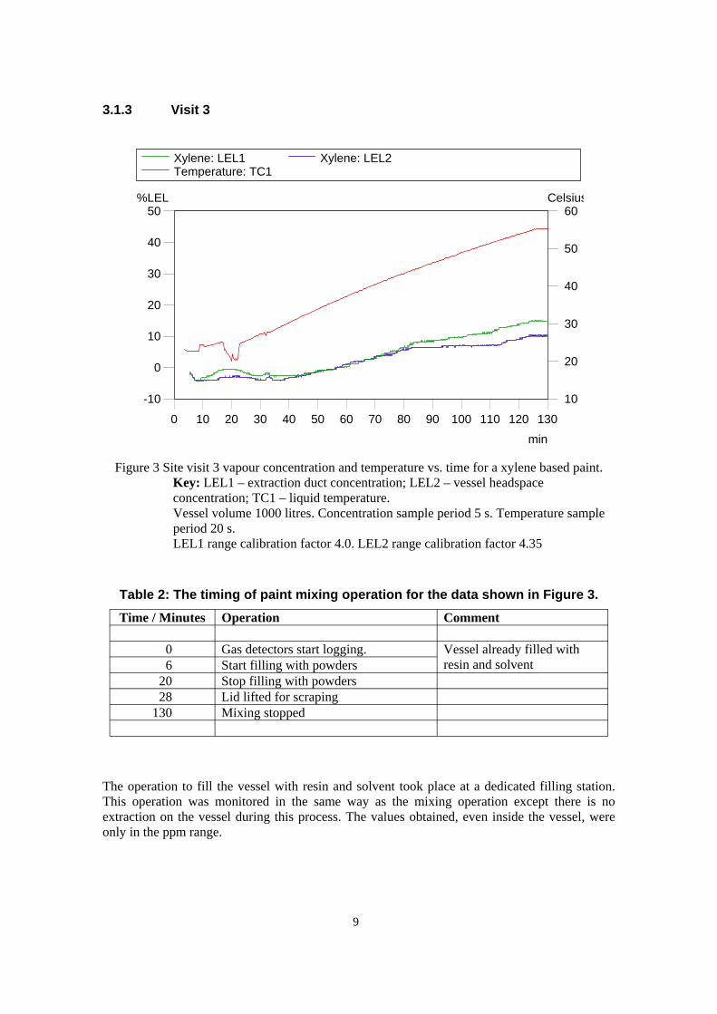
3.1.3 Visit 3
Xylene: LEL1 Xylene: LEL2Temperature: TC1
-10
0
10
20
30
40
50%LEL
10
20
30
40
50
60Celsius
0 10 20 30 40 50 60 70 80 90 100 110 120 130
min
Figure 3 Site visit 3 vapour concentration and temperature vs. time for a xylene based paint. Key: LEL1 – extraction duct concentration; LEL2 – vessel headspace concentration; TC1 – liquid temperature. Vessel volume 1000 litres. Concentration sample period 5 s. Temperature sample period 20 s. LEL1 range calibration factor 4.0. LEL2 range calibration factor 4.35
Table 2: The timing of paint mixing operation for the data shown in Figure 3.
Time / Minutes Operation Comment
0 Gas detectors start logging. Vessel already filled with resin and solvent 6 Start filling with powders
20 Stop filling with powders 28 Lid lifted for scraping 130 Mixing stopped
The operation to fill the vessel with resin and solvent took place at a dedicated filling station. This operation was monitored in the same way as the mixing operation except there is no extraction on the vessel during this process. The values obtained, even inside the vessel, were only in the ppm range.
9
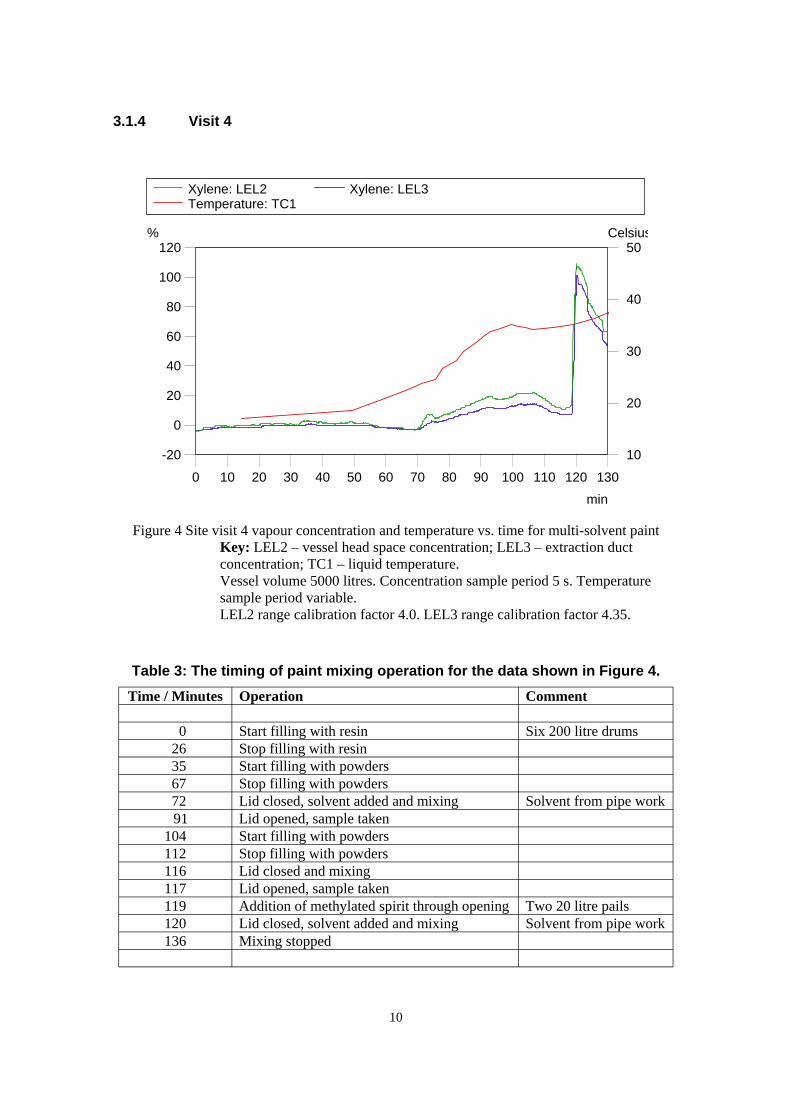
3.1.4 Visit 4
Xylene: LEL2 Xylene: LEL3Temperature: TC1
-20
0
20
40
60
80
100
120%
10
20
30
40
50Celsius
0 10 20 30 40 50 60 70 80 90 100 110 120 130
min
Figure 4 Site visit 4 vapour concentration and temperature vs. time for multi-solvent paint Key: LEL2 – vessel head space concentration; LEL3 – extraction duct concentration; TC1 – liquid temperature. Vessel volume 5000 litres. Concentration sample period 5 s. Temperature sample period variable. LEL2 range calibration factor 4.0. LEL3 range calibration factor 4.35.
Table 3: The timing of paint mixing operation for the data shown in Figure 4. Time / Minutes Operation Comment
0 Start filling with resin Six 200 litre drums 26 Stop filling with resin 35 Start filling with powders 67 Stop filling with powders 72 Lid closed, solvent added and mixing Solvent from pipe work 91 Lid opened, sample taken 104 Start filling with powders 112 Stop filling with powders 116 Lid closed and mixing 117 Lid opened, sample taken 119 Addition of methylated spirit through opening Two 20 litre pails 120 Lid closed, solvent added and mixing Solvent from pipe work 136 Mixing stopped
10
The gas detector calibration factor for n-butanol is the same as the calibration factor for xylene. For the data shown in Figure 4 the calibration factor for xylene was used. The readings on the graph after 119 minutes will be approximately twice the true value due to the difference in calibration factors between methylated spirit and xylene. There is no easy way to accurately correct for this difference.
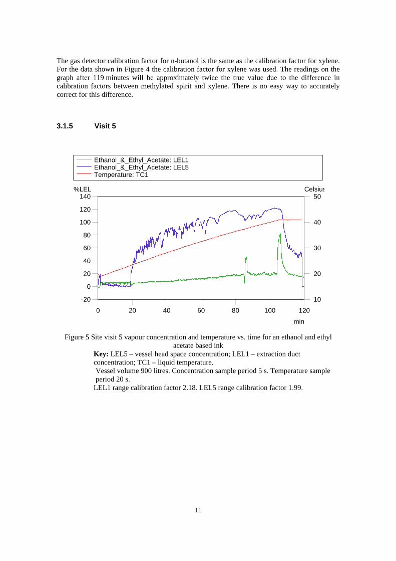
3.1.5 Visit 5
Ethanol_&_Ethyl_Acetate: LEL1Ethanol_&_Ethyl_Acetate: LEL5Temperature: TC1
-20
0
20
40
60
80
100
120
140%LEL
10
20
30
40
50Celsius
0 20 40 60 80 100 120
min
Figure 5 Site visit 5 vapour concentration and temperature vs. time for an ethanol and ethyl acetate based ink
Key: LEL5 – vessel head space concentration; LEL1 – extraction duct concentration; TC1 – liquid temperature. Vessel volume 900 litres. Concentration sample period 5 s. Temperature sample period 20 s.
LEL1 range calibration factor 2.18. LEL5 range calibration factor 1.99.
11

Table 4: The timing of paint mixing operation for the data shown in Figure 5. Time / Minutes Operation Comment
0 Gas detectors start logging. Vessel already filled
with resin and solvent 1 Extraction on 2 Start filling with powders 18 Stop filling with powders 19 Lid closed, extraction stopped, mixing continued 104 Split duct found and taped up, 106 Mixer stopped
The gas detector calibration factor for ethanol is less that the calibration factor for ethyl acetate. For the data shown in Figure 5 the calibration factor for ethyl acetate was used. The graph will show readings that are slightly higher than the true values. There is no easy way to accurately correct for this difference.
3.2 IGNITION TESTS Table 5: Summary of the results from the ignition tests.
Test No, Coating, Flash Point & Solvent
Temperature Ignition Source
Configuration Result
1 Paint 24oC Xylene 62oC Match head & 1 kJ Chemical
Open vessel, loose lid, closed.
No ignition
2 Paint 24oC Xylene 58oC 1 kJ Chemical Closed vessel, top open.
No ignition
3 Paint 24oC Xylene 55oC 1 kJ Chemical Open vessel, loose lid, closed, stirring.
Ignition, flash just below the lid
1 Ink 4oC Ethyl Acetate/ Ethanol
39oC Match head Open vessel, loose lid, closed.
Ignition, explosion, lid lifted
2 Ink 4oC Ethyl Acetate/ Ethanol
38oC Match head Closed vessel, top open.
Ignition, fire
3 Ink 4oC Ethyl Acetate/ Ethanol
38oC Match head Open vessel, loose lid, closed, stirring.
Ignition, explosion, lid lifted
12
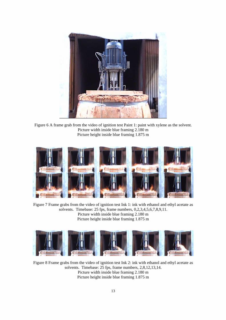
Figure 6 A frame grab from the video of ignition test Paint 1: paint with xylene as the solvent. Picture width inside blue framing 2.180 m Picture height inside blue framing 1.875 m
Figure 7 Frame grabs from the video of ignition test Ink 1: ink with ethanol and ethyl acetate as solvents. Timebase: 25 fps, frame numbers, 0,2,3,4,5,6,7,8,9,11.
Picture width inside blue framing 2.180 m Picture height inside blue framing 1.875 m
Figure 8 Frame grabs from the video of ignition test Ink 2: ink with ethanol and ethyl acetate as solvents. Timebase: 25 fps, frame numbers, 2,8,12,13,14.
Picture width inside blue framing 2.180 m Picture height inside blue framing 1.875 m
13
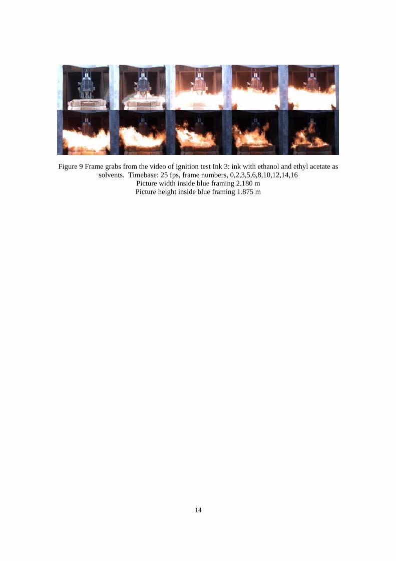
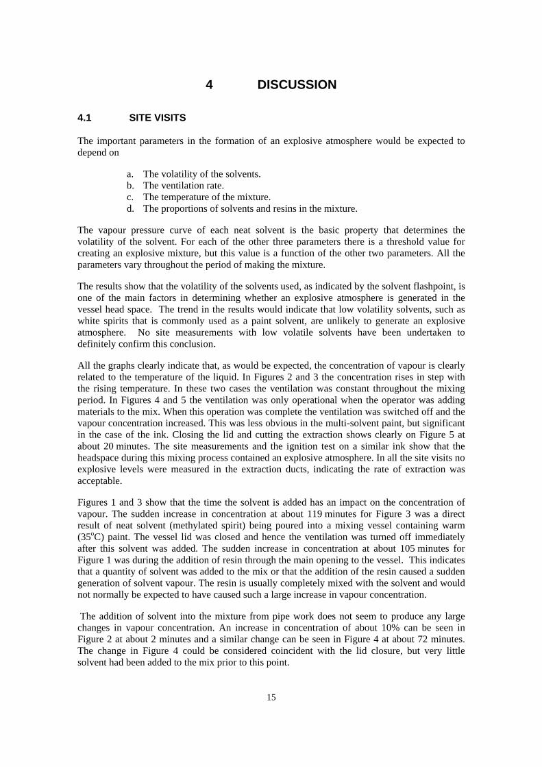
Figure 9 Frame grabs from the video of ignition test Ink 3: ink with ethanol and ethyl acetate as solvents. Timebase: 25 fps, frame numbers, 0,2,3,5,6,8,10,12,14,16
Picture width inside blue framing 2.180 m Picture height inside blue framing 1.875 m
14
4 DISCUSSION
4.1 SITE VISITS The important parameters in the formation of an explosive atmosphere would be expected to depend on
a. The volatility of the solvents. b. The ventilation rate. c. The temperature of the mixture. d. The proportions of solvents and resins in the mixture.
The vapour pressure curve of each neat solvent is the basic property that determines the volatility of the solvent. For each of the other three parameters there is a threshold value for creating an explosive mixture, but this value is a function of the other two parameters. All the parameters vary throughout the period of making the mixture.
The results show that the volatility of the solvents used, as indicated by the solvent flashpoint, is one of the main factors in determining whether an explosive atmosphere is generated in the vessel head space. The trend in the results would indicate that low volatility solvents, such as white spirits that is commonly used as a paint solvent, are unlikely to generate an explosive atmosphere. No site measurements with low volatile solvents have been undertaken to definitely confirm this conclusion.
All the graphs clearly indicate that, as would be expected, the concentration of vapour is clearly related to the temperature of the liquid. In Figures 2 and 3 the concentration rises in step with the rising temperature. In these two cases the ventilation was constant throughout the mixing period. In Figures 4 and 5 the ventilation was only operational when the operator was adding materials to the mix. When this operation was complete the ventilation was switched off and the vapour concentration increased. This was less obvious in the multi-solvent paint, but significant in the case of the ink. Closing the lid and cutting the extraction shows clearly on Figure 5 at about 20 minutes. The site measurements and the ignition test on a similar ink show that the headspace during this mixing process contained an explosive atmosphere. In all the site visits no explosive levels were measured in the extraction ducts, indicating the rate of extraction was acceptable.
Figures 1 and 3 show that the time the solvent is added has an impact on the concentration of vapour. The sudden increase in concentration at about 119 minutes for Figure 3 was a direct result of neat solvent (methylated spirit) being poured into a mixing vessel containing warm (35oC) paint. The vessel lid was closed and hence the ventilation was turned off immediately after this solvent was added. The sudden increase in concentration at about 105 minutes for Figure 1 was during the addition of resin through the main opening to the vessel. This indicates that a quantity of solvent was added to the mix or that the addition of the resin caused a sudden generation of solvent vapour. The resin is usually completely mixed with the solvent and would not normally be expected to have caused such a large increase in vapour concentration.
The addition of solvent into the mixture from pipe work does not seem to produce any large changes in vapour concentration. An increase in concentration of about 10% can be seen in Figure 2 at about 2 minutes and a similar change can be seen in Figure 4 at about 72 minutes. The change in Figure 4 could be considered coincident with the lid closure, but very little solvent had been added to the mix prior to this point.
15

Neat solvent addition during mixing, especially during the latter stages of mixing when the mixture is warm, is considered as one of the most hazardous operations as it can generate transient explosive atmospheres in the vessel. Ideally this operation should be avoided, but often this is not possible as many mixing operations require adjustment of the mixture properties in the final stages by addition of small amounts of solvents and other materials. If such additions cannot be eliminated, appropriate control measures need to be implemented to reduce the risk of an ignition and, where possible, remove personnel from the immediate vicinity of the opening to the mixing vessel.
The addition of resin to any solvent will in most cases reduce the vapour pressure of the solvent. The consequence is that the fraction of solvent in the mix can determine the amount of vapour in the head space. The paint mixes in Figures 1 to 3 contain approximately 15% solvent by weight. The paint mix in Figure 4 contains approximately 7.9% solvent by weight. The ink in Figure 5 contains 64% solvent by weight. A reduction in solvent vapour pressure caused by a resin will increase the flashpoint of the mixture. The extent of this change will depend on the ratio of solvent to resin.
Appendix A outlines the key factors, based on the findings of the site tests, that need to be taken into account in any risk assessment of a mixing process. Due to the diverse nature of the coatings mixing industry it is not possible to give a generic risk assessment that would cover the whole industry. It is essential that site specific assessments are made for every operation. Appendix A should be regarded as an aide-memoir of what factors need to be considered, not all of which would be relevant to every mixing operation.
4.2 IGNITION TESTS
The conditions used for the ignition tests are considered to be representative of small batch operations using open vessels or vessels with loose fitting lids. The test vessel was not fitted with local exhaust ventilation (LEV), but as it was located in a well ventilated area the conditions in the vessel head space were judged to be similar to those in a vessel with LEV.
Liquid ejection was one of the expected consequences of an explosion, but this was not observed in any of the tests. On the basis of this result, liquid ejection cannot be also ruled out for larger batch vessels or closed vessels with an open manway, where scale and different confinement conditions may create the conditions necessary for liquid ejection.
4.3 FURTHER WORK
The addition of solvents by pouring the liquid into the mix from a drum or a pail needs further investigation. It clearly gives large changes in vapour concentration. This could be because the liquid is being poured onto the surface of warm paint or simply due to the pouring the liquid. Where the manual addition of solvents to a mixture leads to a transient explosive atmosphere inside the vessel then ideally other methods of solvent addition, that remove personnel from the immediate vicinity of the opening to the mixing vessel, should be adopted. These methods could include air driven pumps, siphons, gravity feeds with remotely operated valves. In many cases this is not a feasible option, in which case appropriate control measures need to be implemented to reduce the risk of an ignition.
This phase of the project has concentrated entirely on mixing operations in the coatings manufacturing process. In the coatings industry there are other activities, e.g., cleaning, that may take place less frequently, but could be potentially more hazardous. Cleaning uses neat solvents, i.e., solvents not mixed with resins, and these are equally likely to generate explosive atmospheres. Other operations also handle neat solvents, e.g., at the ink manufacturer we did not monitor the filling of the mobile vessel with the solvents. 16

Throughout the site visits no consideration was given to the possibility that the powders added to the mixes could be explosive. The extent of the use of explosive dusts within the coatings industry has not been assessed and consequently the possible generation of explosive hybrid mixtures cannot be quantified.
17

5 CONCLUSIONS
Five site visits, to two paint manufacturers and one ink manufacturer, have been undertaken to measure the vapour concentrations in and around mixing units. An explosive mixture, i.e., above 100% LEL, of vapour and air was found inside the mixing vessel at the ink manufacturer (ethanol/ethyl acetate based ink). Non-explosive mixtures of vapour and air in the % LEL range were found inside the mixing vessels at the paint manufacturers (xylene based paints). The results confirmed that the important parameters in the formation of an explosive atmosphere are as follows:
a) The volatility of the solvents. b) The ventilation rate. c) The temperature of the mix. d) The proportions of solvents and resins in the mix.
Mixtures based on solvents with lower volatilities than those studied in the site visits would be expected to generate non-explosive mixtures in the mixing vessel. This conclusion has not been confirmed by site measurements.
Manual addition of solvents during mixing, especially in the latter stages of the mixing process when the mixture is warm, can generate high transient vapour concentrations in the mixing vessel. This is considered one of the most hazardous operations undertaken during the mixing process. If such additions cannot be avoided it is important to ensure that control measures to reduce the risk of an ignition, and for COSHH purposes, are maintained throughout the whole mixing cycle, for example always having automatic activation of the LEV system whenever a port is opened for an addition. It is recommended that further work be undertaken to determine more precisely the conditions needed to generate these transient atmospheres and their duration.
Ignition tests, using an experimental rig representative of small batch operations using open vessels or vessels with loose fitting lids, have been undertaken. Ink (ethanol/ethyl acetate based) and paint mixtures (xylene based) were mixed to give temperatures similar to those found on the site visits. On igniting the vapour generated in the mixing vessel an explosion and fire occurred with all three ink tests. A small flash occurred during one of the paint tests. There was no liquid ejected from the vessel during any of the tests. On the basis of this result liquid ejection cannot be also ruled out for larger batch vessels or closed vessels with an open manway, where scale and different confinement conditions may create the conditions necessary for liquid ejection.
Other operations associated with mixing operations, e.g. the cleaning of vessels between batches, have not been studied. Cleaning uses neat solvents, with the potential of generating high vapour concentrations within the vessel. Further work would be required to quantify the risks of these associated operations.
No account has been taken of the fact that some of the powders used are also explosible. Further work would be required to assess the explosion hazard such powders and hybrid mixtures of vapour and dust may generate.
18

6 REFERENCES
1) Dr D K Pritchard, Health and Safety Laboratory. Assessment of fire and explosion risks in coating mixing operations. HSL Report EC/04/15, September 2005
19
7 GLOSSARY
Explosion: An explosion is a release of energy sufficient to cause a pressure wave.
Flash Fire: The combustion of a flammable vapour and air mixture in which flame passes through that mixture at less than sonic velocity, such that negligible damaging overpressure is generated.
20
8 APPENDIX A – RISK ASSESSMENT
In undertaking a risk assessment of the explosion hazards that may arise from coatings mixing operations the following factors need to be considered.
Solvent volatility The higher the volatility of the solvents used the greater risk, for a given set of conditions, of an explosive atmosphere being generated. The flashpoint or boiling point can be used as a measure of the solvents volatility, the lower the flashpoint or boiling point the greater the volatility. The results from the present study indicate that low volatility solvents, such as white spirits, are unlikely to generate an explosive atmosphere, unless there are some unusual conditions like high temperature or splashing that could enhance the rate of vapour generation. Note that if a solvent is dispersed as fine mist (droplet sizes in the range of a few microns to tens of microns) then an explosive atmosphere can be generated even though the temperature of the solvent is below its flashpoint.
Ventilation rate If LEV is being relied upon to prevent an explosive atmosphere being formed the ventilation rate must also be great enough to prevent an explosive atmosphere also building up in the exhaust ducting. Often the exhaust ducting from individual vessels connect into common ducting. In these circumstances ignition in one vessel, or an ignition in the ducting itself, could result in an explosion propagating between mixing vessels, turning what would have been a minor event in one vessel to a major incident involving a number of vessels.
Mixture temperature Increasing the temperature of the mixture increases the vapour pressure and thus the likelihood of an explosive atmosphere being formed. It is, therefore, important to take into account the final temperature of the mixture as well as initial temperature in assessing whether there is an explosion hazard.
Solvent/resins mixtures Resin or other solids in solvents will reduce the vapour pressure of the solvent and thus the likelihood of an explosive atmosphere being formed. Addition of solid/liquid mixtures to mixing vessels is thus a better option than addition of solvents and solids separately.
Solvent addition Manual addition of solvents during mixing, especially in the latter stages when the mixture is warm, can generate transient explosive atmospheres in the vessel. This is considered one of the most hazardous operations undertaken during the mixing process. Particular attention needs to be paid to such an operation and appropriate control measures implemented to reduce the risk of an ignition.
Liquid ejection The present study indicates that liquid ejection is not a hazard for small batch operations using open vessels or vessels fitted with loose lids. It cannot be assumed that this could not also occur for larger batch operation or for closed vessels with open manways.
Associated activities Activities associated with the mixing operations, e.g. the cleaning of vessels, that use neat solvents also have the potential to generate explosive atmospheres within the vessel. Such activities also need to be included in the risk assessment.
Spillages The present study indicates that explosive atmospheres are unlikely to be generated outside the mixing vessels during normal operation. A solvent spillage during loading of vessels or leaks from piping and vessels has the potential to generate an external explosive atmosphere, albeit for a short period while the vapour disperses. The likelihood and consequences of a spill or leak and the vapour igniting need to be considered in the risk assessment.
21

Hybrid mixtures Hybrid mixtures of dusts and vapours can form an explosive atmosphere even though the concentrations of the dust and vapour are below the lower explosive limits for each component. Dusts that would normally not be explosible in air can also explode in atmospheres containing low concentrations (below the lower explosive limit) of vapour. This study has not looked at the hazards from hybrid mixtures, so it is not known if they do pose an explosion hazard in mixing operations. Until further information is available, it would be a conservative approach to assume an explosion hazard is possible in processes where concentrations of vapour and dust approaching their lower explosive limits may be present at the same time.
Published by the Health and Safety Executive 02/07
Assessment of fire and explosionrisks in coating mixing operations
Health and Safety Executive
RR526
www.hse.gov.uk
The Dangerous Substances and Explosive AtmospheresRegulations 2002 (DSEAR) necessitate a re-assessment ofthe fire and explosion risks arising from the formation ofexplosive atmospheres in and around coatings mixingvessels. A programme of work has been commissionedby HSE to review the hazards that would need to becovered by the risk assessment and to carry outexperimental work to fill in any gaps in knowledge. Theoutcome of the project would be used to inform thedevelopment of HSE’s DSEAR Enforcement Policy oncoatings mixing operations. This report presents thefindings of Phase 2 of the project, the objectives of whichwere to:
n Undertake site visits to make vapour concentrationmeasurements in and around coatings mixingvessels.
n Perform ignition tests on example coatings at HSL.
This report and the work it describes were funded bythe Health and Safety Executive (HSE). Its contents,including any opinions and/or conclusions expressed, arethose of the authors alone and do not necessarily reflectHSE policy.