Embed Size (px)
Citation preview
Replacement Parts List No. 700026200Revision E 05/2017
Daikin McQuay
Pathfinder®
Screw CompressorAir-Cooled Chiller
3 CircuitAWS
400 - 550 Vintage B
Unit Revision 0B (Code 62)
To find your Daikin Applied parts distributor, call 1-800-377-2787 or visit www.DaikinApplied.com
Air Cooled Screw Chiller, AWS 400-550, 3-Ckt, Vint. B, Unit Rev. 0B RPL Rev. E 05/17 RPL 7000262 / Page 2
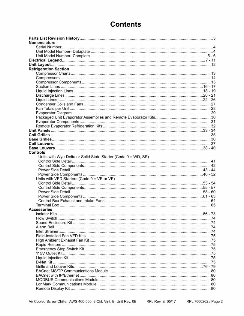
Contents
Parts List Revision History ........................................................................................................................3Nomenclature Serial Number ........................................................................................................................................4 Unit Model Number- Dataplate ..............................................................................................................4 Unit Model Number- Complete .........................................................................................................5 - 6Electrical Legend .................................................................................................................................7 - 11Unit Layout ................................................................................................................................................12Refrigeration Section Compressor Charts ..............................................................................................................................13 Compressors ........................................................................................................................................14 Compressor Components ....................................................................................................................15 Suction Lines ................................................................................................................................16 - 17 Liquid Injection Lines ....................................................................................................................18 - 19 Discharge Lines ............................................................................................................................20 - 21 Liquid Lines ...................................................................................................................................22 - 26 Condenser Coils and Fans ..................................................................................................................27 Fan Totals per Unit ...............................................................................................................................28 Evaporator Diagram .............................................................................................................................29 Packaged Unit Evaporator Assemblies and Remote Evaporator Kits ..................................................30 Evaporator Components ......................................................................................................................31 Remote Evaporator Refrigeration Kits .................................................................................................32Unit Panels .........................................................................................................................................33 - 34Coil Grilles.................................................................................................................................................35Base Grilles ...............................................................................................................................................36Coil Louvers ..............................................................................................................................................37Base Louvers .....................................................................................................................................38 - 40Controls Units with Wye-Delta or Solid State Starter (Code 9 = WD, SS) Control Side Detail .............................................................................................................................41 Control Side Components ..................................................................................................................42 Power Side Detail .......................................................................................................................43 - 44 Power Side Components ............................................................................................................46 - 52 Units with VFD Starters (Code 9 = VE or VF) Control Side Detail ......................................................................................................................53 - 54 Control Side Components ...........................................................................................................55 - 57 Power Side Detail .......................................................................................................................58 - 60 Power Side Components ............................................................................................................61 - 63 Control Box Exhaust and Intake Fans ...............................................................................................64 Terminal Box ........................................................................................................................................65Accessories Isolator Kits ...................................................................................................................................66 - 73 Flow Switch ..........................................................................................................................................74 Sound Enclosure Kit ............................................................................................................................74 Alarm Bell .............................................................................................................................................74 Inlet Strainer .........................................................................................................................................74 Field-Installed Fan VFD Kits ................................................................................................................75 High Ambient Exhaust Fan Kit .............................................................................................................75 Rapid Restore ......................................................................................................................................75 Emergency Stop Switch Kit ..................................................................................................................75 115V Outlet Kit .....................................................................................................................................75 Liquid Injection Kit ................................................................................................................................75 D-Net Kit ..............................................................................................................................................75 Grille and Louver Kits ....................................................................................................................76 - 79 BACnet MS/TP Communications Module ............................................................................................80 BACnet with IP/Ethernet ......................................................................................................................80 MODBUS Communications Module .....................................................................................................80 LonMark Communications Module ......................................................................................................80 Remote Display Kit ..............................................................................................................................80
Air Cooled Screw Chiller, AWS 400-550, 3-Ckt, Vint. B, Unit Rev. 0B RPL Rev. E 05/17 RPL 7000262 / Page 3
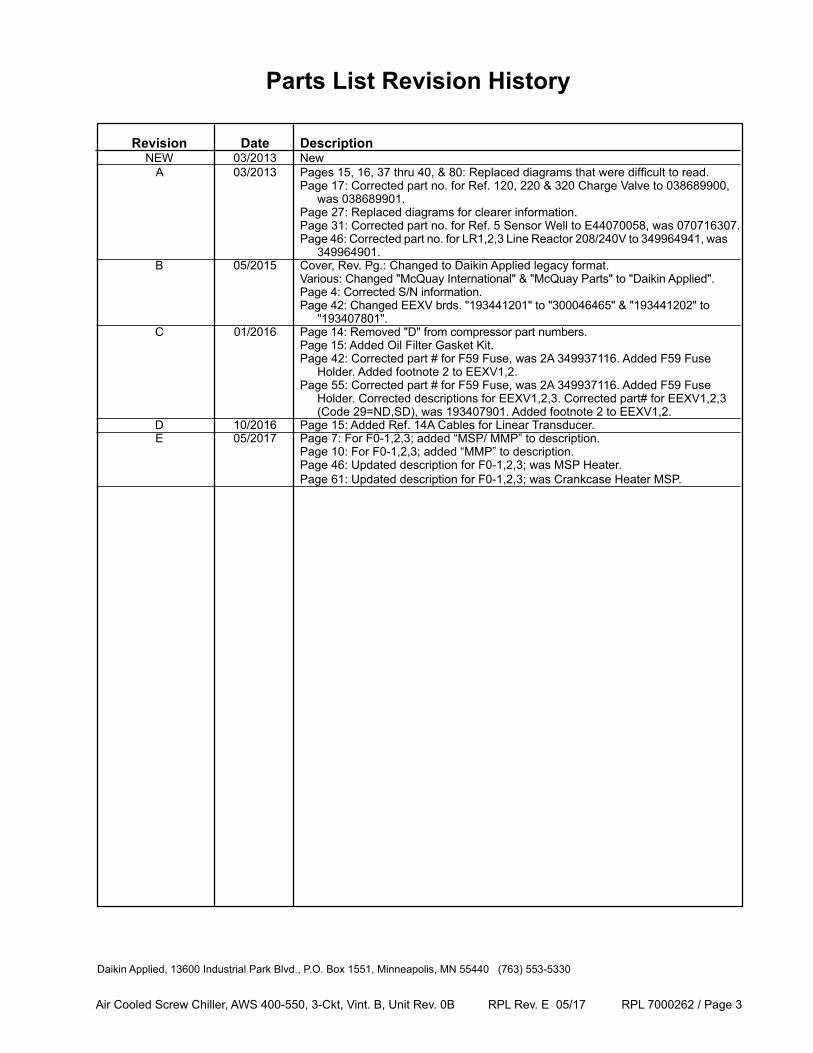
Revision Date Description NEW 03/2013 New A 03/2013 Pages 15, 16, 37 thru 40, & 80: Replaced diagrams that were difficult to read. Page 17: Corrected part no. for Ref. 120, 220 & 320 Charge Valve to 038689900, was 038689901. Page 27: Replaced diagrams for clearer information. Page 31: Corrected part no. for Ref. 5 Sensor Well to E44070058, was 070716307. Page 46: Corrected part no. for LR1,2,3 Line Reactor 208/240V to 349964941, was 349964901. B 05/2015 Cover, Rev. Pg.: Changed to Daikin Applied legacy format. Various: Changed "McQuay International" & "McQuay Parts" to "Daikin Applied". Page 4: Corrected S/N information. Page 42: Changed EEXV brds. "193441201" to "300046465" & "193441202" to "193407801". C 01/2016 Page 14: Removed "D" from compressor part numbers. Page 15: Added Oil Filter Gasket Kit. Page 42: Corrected part # for F59 Fuse, was 2A 349937116. Added F59 Fuse Holder. Added footnote 2 to EEXV1,2. Page 55: Corrected part # for F59 Fuse, was 2A 349937116. Added F59 Fuse Holder. Corrected descriptions for EEXV1,2,3. Corrected part# for EEXV1,2,3 (Code 29=ND,SD), was 193407901. Added footnote 2 to EEXV1,2. D 10/2016 Page 15: Added Ref. 14A Cables for Linear Transducer. E 05/2017 Page 7: For F0-1,2,3; added “MSP/ MMP” to description. Page 10: For F0-1,2,3; added “MMP” to description. Page 46: Updated description for F0-1,2,3; was MSP Heater. Page 61: Updated description for F0-1,2,3; was Crankcase Heater MSP.
Parts List Revision History
Daikin Applied, 13600 Industrial Park Blvd., P.O. Box 1551, Minneapolis, MN 55440 (763) 553-5330
Air Cooled Screw Chiller, AWS 400-550, 3-Ckt, Vint. B, Unit Rev. 0B RPL Rev. E 05/17 RPL 7000262 / Page 4
Nomenclature
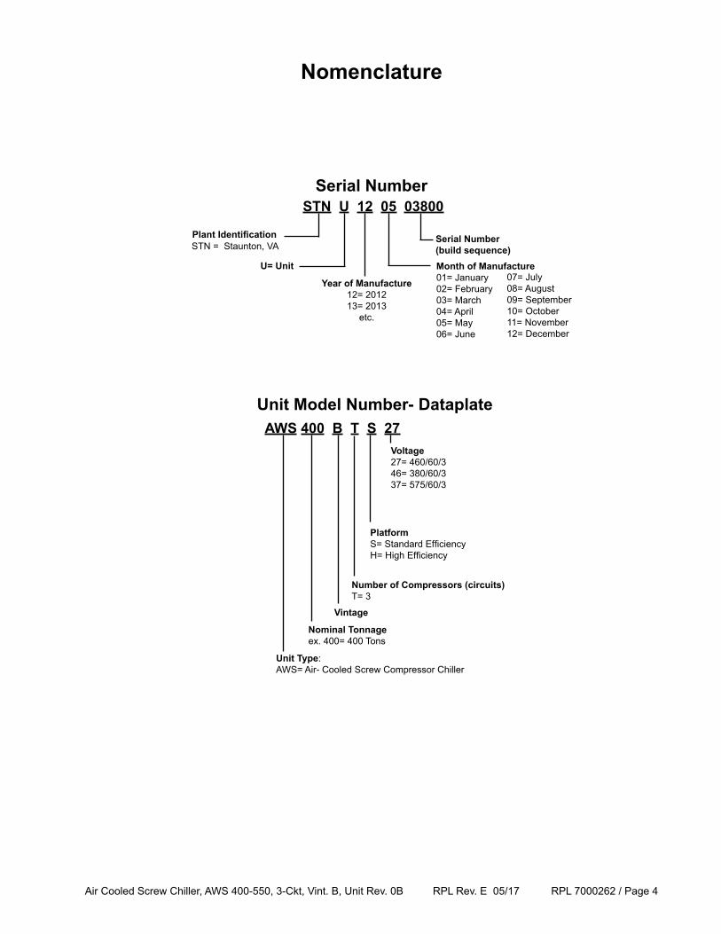
AWS 400 B T S 27Unit Model Number- Dataplate
Unit Type: AWS= Air- Cooled Screw Compressor Chiller
Nominal Tonnageex. 400= 400 Tons
Vintage
Number of Compressors (circuits)T= 3
STN U 12 05 03800
Plant IdentificationSTN = Staunton, VA
Year of Manufacture12= 201213= 2013
etc.
U= Unit
Serial Number (build sequence)Month of Manufacture01= January02= February03= March04= April05= May06= June
07= July08= August09= September10= October11= November12= December
Serial Number
PlatformS= Standard Efficiency H= High Efficiency
Voltage27= 460/60/346= 380/60/337= 575/60/3
Air Cooled Screw Chiller, AWS 400-550, 3-Ckt, Vint. B, Unit Rev. 0B RPL Rev. E 05/17 RPL 7000262 / Page 5
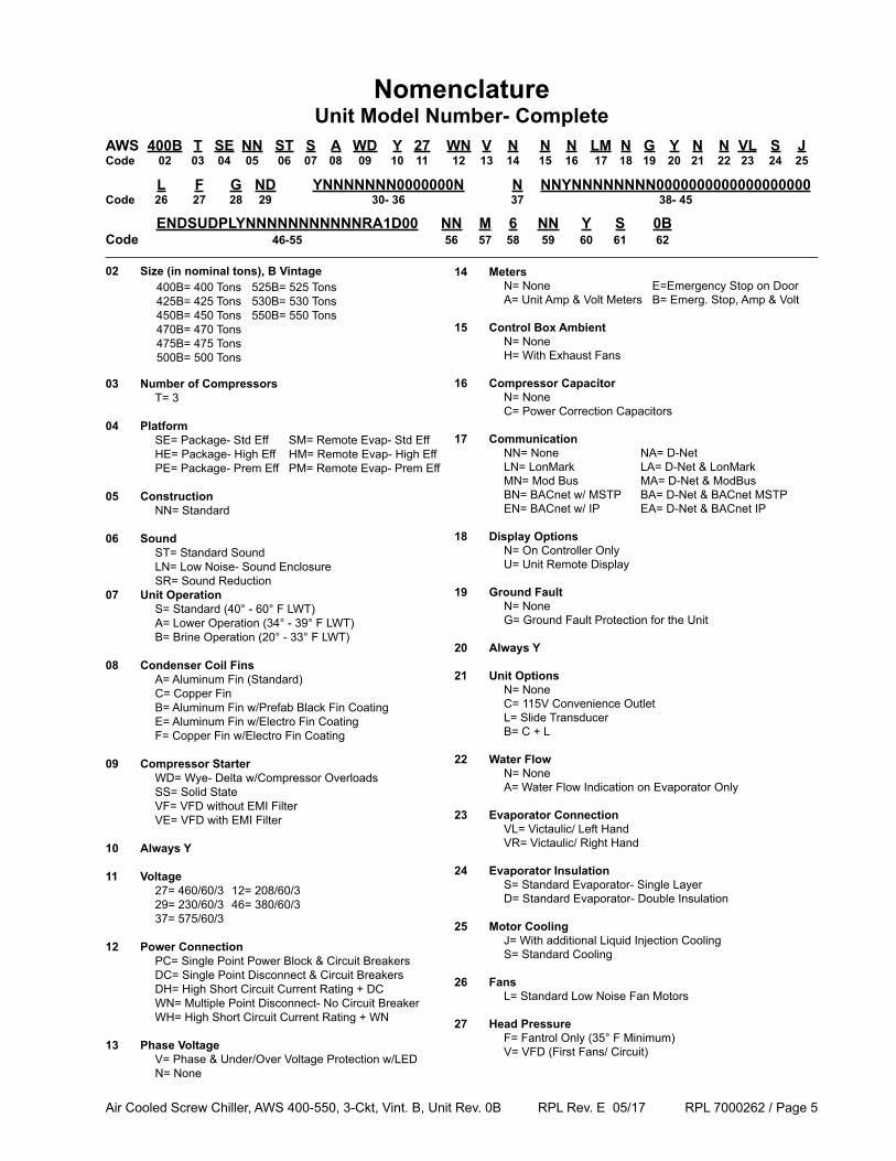
AWS 400B T SE NN ST S A WD Y 27 WN V N N N LM N G Y N N VL S JCode 02 03 04 05 06 07 08 09 10 11 12 13 14 15 16 17 18 19 20 21 22 23 24 25
L F G ND YNNNNNNN0000000N N NNYNNNNNNNN0000000000000000000Code 26 27 28 29 30- 36 37 38- 45
NomenclatureUnit Model Number- Complete
ENDSUDPLYNNNNNNNNNNNRA1D00 NN M 6 NN Y S 0BCode 46-55 56 57 58 59 60 61 62
02 Size (in nominal tons), B Vintage
03 Number of Compressors T= 3
04 Platform SE= Package- Std Eff SM= Remote Evap- Std Eff HE= Package- High Eff HM= Remote Evap- High Eff PE= Package- Prem Eff PM= Remote Evap- Prem Eff
05 Construction NN= Standard
06 Sound ST= Standard Sound LN= Low Noise- Sound Enclosure SR= Sound Reduction07 Unit Operation S= Standard (40° - 60° F LWT) A= Lower Operation (34° - 39° F LWT) B= Brine Operation (20° - 33° F LWT)
08 Condenser Coil Fins A= Aluminum Fin (Standard) C= Copper Fin B= Aluminum Fin w/Prefab Black Fin Coating E= Aluminum Fin w/Electro Fin Coating F= Copper Fin w/Electro Fin Coating
09 Compressor Starter WD= Wye- Delta w/Compressor Overloads SS= Solid State VF= VFD without EMI Filter VE= VFD with EMI Filter
10 Always Y
11 Voltage 27= 460/60/3 12= 208/60/3 29= 230/60/3 46= 380/60/3 37= 575/60/3
12 Power Connection PC= Single Point Power Block & Circuit Breakers DC= Single Point Disconnect & Circuit Breakers DH= High Short Circuit Current Rating + DC WN= Multiple Point Disconnect- No Circuit Breaker WH= High Short Circuit Current Rating + WN
13 Phase Voltage V= Phase & Under/Over Voltage Protection w/LED N= None
14 Meters N= None E=Emergency Stop on Door A= Unit Amp & Volt Meters B= Emerg. Stop, Amp & Volt
15 Control Box Ambient N= None H= With Exhaust Fans
16 Compressor Capacitor N= None C= Power Correction Capacitors
17 Communication NN= None NA= D-Net LN= LonMark LA= D-Net & LonMark MN= Mod Bus MA= D-Net & ModBus BN= BACnet w/ MSTP BA= D-Net & BACnet MSTP EN= BACnet w/ IP EA= D-Net & BACnet IP
18 Display Options N= On Controller Only U= Unit Remote Display
19 Ground Fault N= None G= Ground Fault Protection for the Unit
20 Always Y
21 Unit Options N= None C= 115V Convenience Outlet L= Slide Transducer B= C + L
22 Water Flow N= None A= Water Flow Indication on Evaporator Only
23 Evaporator Connection VL= Victaulic/ Left Hand VR= Victaulic/ Right Hand
24 Evaporator Insulation S= Standard Evaporator- Single Layer D= Standard Evaporator- Double Insulation
25 Motor Cooling J= With additional Liquid Injection Cooling S= Standard Cooling
26 Fans L= Standard Low Noise Fan Motors
27 Head Pressure F= Fantrol Only (35° F Minimum) V= VFD (First Fans/ Circuit)
400B= 400 Tons 525B= 525 Tons425B= 425 Tons 530B= 530 Tons450B= 450 Tons 550B= 550 Tons470B= 470 Tons 475B= 475 Tons 500B= 500 Tons
Air Cooled Screw Chiller, AWS 400-550, 3-Ckt, Vint. B, Unit Rev. 0B RPL Rev. E 05/17 RPL 7000262 / Page 6
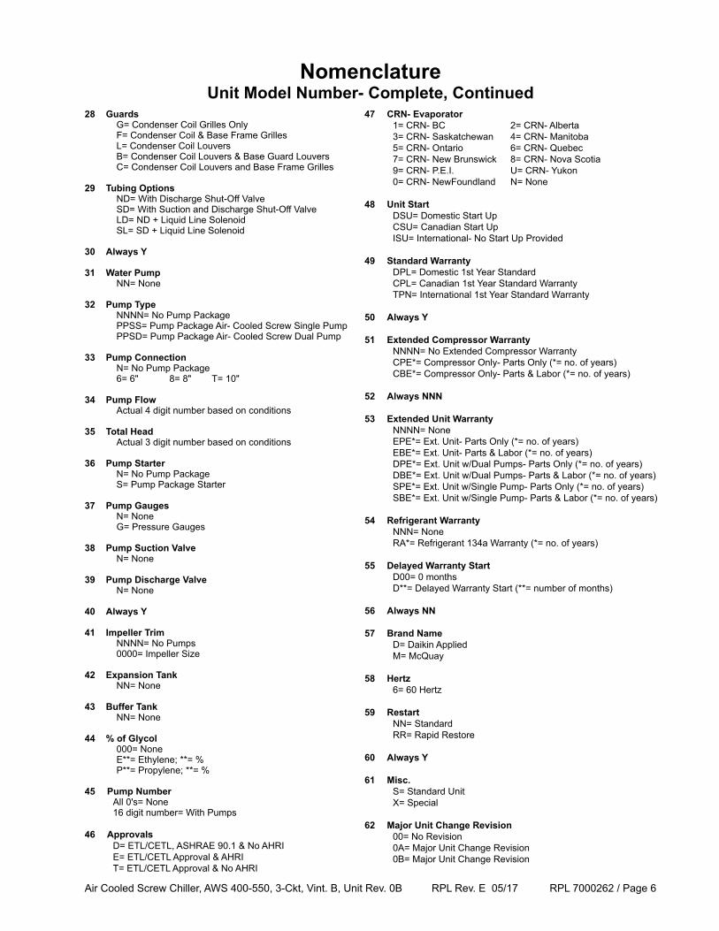
28 Guards G= Condenser Coil Grilles Only F= Condenser Coil & Base Frame Grilles L= Condenser Coil Louvers B= Condenser Coil Louvers & Base Guard Louvers C= Condenser Coil Louvers and Base Frame Grilles
29 Tubing Options ND= With Discharge Shut-Off Valve SD= With Suction and Discharge Shut-Off Valve LD= ND + Liquid Line Solenoid SL= SD + Liquid Line Solenoid
30 Always Y
31 Water Pump NN= None
32 Pump Type NNNN= No Pump Package PPSS= Pump Package Air- Cooled Screw Single Pump PPSD= Pump Package Air- Cooled Screw Dual Pump
33 Pump Connection N= No Pump Package 6= 6" 8= 8" T= 10"
34 Pump Flow Actual 4 digit number based on conditions
35 Total Head Actual 3 digit number based on conditions
36 Pump Starter N= No Pump Package S= Pump Package Starter
37 Pump Gauges N= None G= Pressure Gauges
38 Pump Suction Valve N= None
39 Pump Discharge Valve N= None
40 Always Y
41 Impeller Trim NNNN= No Pumps 0000= Impeller Size
42 Expansion Tank NN= None
43 Buffer Tank NN= None
44 % of Glycol 000= None E**= Ethylene; **= % P**= Propylene; **= %
45 Pump Number All 0's= None 16 digit number= With Pumps
46 Approvals D= ETL/CETL, ASHRAE 90.1 & No AHRI E= ETL/CETL Approval & AHRI T= ETL/CETL Approval & No AHRI
NomenclatureUnit Model Number- Complete, Continued
47 CRN- Evaporator 1= CRN- BC 2= CRN- Alberta 3= CRN- Saskatchewan 4= CRN- Manitoba 5= CRN- Ontario 6= CRN- Quebec 7= CRN- New Brunswick 8= CRN- Nova Scotia 9= CRN- P.E.I. U= CRN- Yukon 0= CRN- NewFoundland N= None 48 Unit Start DSU= Domestic Start Up CSU= Canadian Start Up ISU= International- No Start Up Provided
49 Standard Warranty DPL= Domestic 1st Year Standard CPL= Canadian 1st Year Standard Warranty TPN= International 1st Year Standard Warranty
50 Always Y
51 Extended Compressor Warranty NNNN= No Extended Compressor Warranty CPE*= Compressor Only- Parts Only (*= no. of years) CBE*= Compressor Only- Parts & Labor (*= no. of years)
52 Always NNN
53 Extended Unit Warranty NNNN= None EPE*= Ext. Unit- Parts Only (*= no. of years) EBE*= Ext. Unit- Parts & Labor (*= no. of years) DPE*= Ext. Unit w/Dual Pumps- Parts Only (*= no. of years) DBE*= Ext. Unit w/Dual Pumps- Parts & Labor (*= no. of years) SPE*= Ext. Unit w/Single Pump- Parts Only (*= no. of years) SBE*= Ext. Unit w/Single Pump- Parts & Labor (*= no. of years)
54 Refrigerant Warranty NNN= None RA*= Refrigerant 134a Warranty (*= no. of years)
55 Delayed Warranty Start D00= 0 months D**= Delayed Warranty Start (**= number of months)
56 Always NN
57 Brand Name D= Daikin Applied M= McQuay
58 Hertz 6= 60 Hertz
59 Restart NN= Standard RR= Rapid Restore
60 Always Y
61 Misc. S= Standard Unit X= Special
62 Major Unit Change Revision 00= No Revision 0A= Major Unit Change Revision 0B= Major Unit Change Revision
Air Cooled Screw Chiller, AWS 400-550, 3-Ckt, Vint. B, Unit Rev. 0B RPL Rev. E 05/17 RPL 7000262 / Page 7
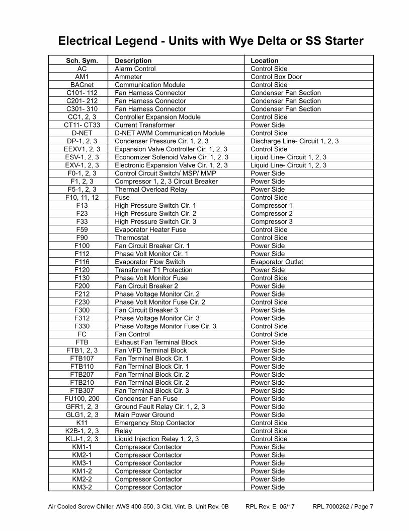
Electrical Legend - Units with Wye Delta or SS Starter Sch. Sym. Description Location AC Alarm Control Control Side AM1 Ammeter Control Box Door BACnet Communication Module Control Side C101- 112 Fan Harness Connector Condenser Fan Section C201- 212 Fan Harness Connector Condenser Fan Section C301- 310 Fan Harness Connector Condenser Fan Section CC1, 2, 3 Controller Expansion Module Control Side CT11- CT33 Current Transformer Power Side D-NET D-NET AWM Communication Module Control Side DP-1, 2, 3 Condenser Pressure Cir. 1, 2, 3 Discharge Line- Circuit 1, 2, 3 EEXV1, 2, 3 Expansion Valve Controller Cir. 1, 2, 3 Control Side ESV-1, 2, 3 Economizer Solenoid Valve Cir. 1, 2, 3 Liquid Line- Circuit 1, 2, 3 EXV-1, 2, 3 Electronic Expansion Valve Cir. 1, 2, 3 Liquid Line- Circuit 1, 2, 3 F0-1, 2, 3 Control Circuit Switch/ MSP/ MMP Power Side F1, 2, 3 Compressor 1, 2, 3 Circuit Breaker Power Side F5-1, 2, 3 Thermal Overload Relay Power Side F10, 11, 12 Fuse Control Side F13 High Pressure Switch Cir. 1 Compressor 1 F23 High Pressure Switch Cir. 2 Compressor 2 F33 High Pressure Switch Cir. 3 Compressor 3 F59 Evaporator Heater Fuse Control Side F90 Thermostat Control Side F100 Fan Circuit Breaker Cir. 1 Power Side F112 Phase Volt Monitor Cir. 1 Power Side F116 Evaporator Flow Switch Evaporator Outlet F120 Transformer T1 Protection Power Side F130 Phase Volt Monitor Fuse Control Side F200 Fan Circuit Breaker 2 Power Side F212 Phase Voltage Monitor Cir. 2 Power Side F230 Phase Volt Monitor Fuse Cir. 2 Control Side F300 Fan Circuit Breaker 3 Power Side F312 Phase Voltage Monitor Cir. 3 Power Side F330 Phase Voltage Monitor Fuse Cir. 3 Control Side FC Fan Control Control Side FTB Exhaust Fan Terminal Block Power Side FTB1, 2, 3 Fan VFD Terminal Block Power Side FTB107 Fan Terminal Block Cir. 1 Power Side FTB110 Fan Terminal Block Cir. 1 Power Side FTB207 Fan Terminal Block Cir. 2 Power Side FTB210 Fan Terminal Block Cir. 2 Power Side FTB307 Fan Terminal Block Cir. 3 Power Side FU100, 200 Condenser Fan Fuse Power Side GFR1, 2, 3 Ground Fault Relay Cir. 1, 2, 3 Power Side GLG1, 2, 3 Main Power Ground Power Side K11 Emergency Stop Contactor Control Side K2B-1, 2, 3 Relay Control Side KLJ-1, 2, 3 Liquid Injection Relay 1, 2, 3 Control Side KM1-1 Compressor Contactor Power Side KM2-1 Compressor Contactor Power Side KM3-1 Compressor Contactor Power Side KM1-2 Compressor Contactor Power Side KM2-2 Compressor Contactor Power Side KM3-2 Compressor Contactor Power Side
Air Cooled Screw Chiller, AWS 400-550, 3-Ckt, Vint. B, Unit Rev. 0B RPL Rev. E 05/17 RPL 7000262 / Page 8
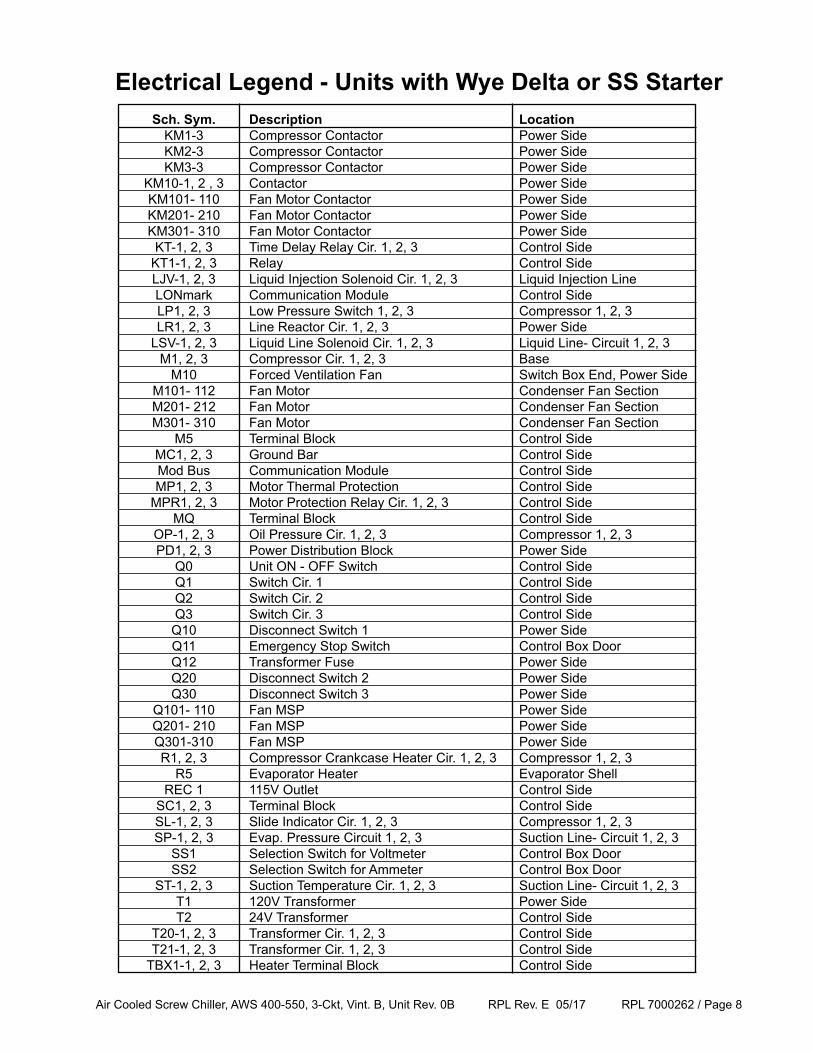
Sch. Sym. Description Location KM1-3 Compressor Contactor Power Side KM2-3 Compressor Contactor Power Side KM3-3 Compressor Contactor Power Side KM10-1, 2 , 3 Contactor Power Side KM101- 110 Fan Motor Contactor Power Side KM201- 210 Fan Motor Contactor Power Side KM301- 310 Fan Motor Contactor Power Side KT-1, 2, 3 Time Delay Relay Cir. 1, 2, 3 Control Side KT1-1, 2, 3 Relay Control Side LJV-1, 2, 3 Liquid Injection Solenoid Cir. 1, 2, 3 Liquid Injection Line LONmark Communication Module Control Side LP1, 2, 3 Low Pressure Switch 1, 2, 3 Compressor 1, 2, 3 LR1, 2, 3 Line Reactor Cir. 1, 2, 3 Power Side LSV-1, 2, 3 Liquid Line Solenoid Cir. 1, 2, 3 Liquid Line- Circuit 1, 2, 3 M1, 2, 3 Compressor Cir. 1, 2, 3 Base M10 Forced Ventilation Fan Switch Box End, Power Side M101- 112 Fan Motor Condenser Fan Section M201- 212 Fan Motor Condenser Fan Section M301- 310 Fan Motor Condenser Fan Section M5 Terminal Block Control Side MC1, 2, 3 Ground Bar Control Side Mod Bus Communication Module Control Side MP1, 2, 3 Motor Thermal Protection Control Side MPR1, 2, 3 Motor Protection Relay Cir. 1, 2, 3 Control Side MQ Terminal Block Control Side OP-1, 2, 3 Oil Pressure Cir. 1, 2, 3 Compressor 1, 2, 3 PD1, 2, 3 Power Distribution Block Power Side Q0 Unit ON - OFF Switch Control Side Q1 Switch Cir. 1 Control Side Q2 Switch Cir. 2 Control Side Q3 Switch Cir. 3 Control Side Q10 Disconnect Switch 1 Power Side Q11 Emergency Stop Switch Control Box Door Q12 Transformer Fuse Power Side Q20 Disconnect Switch 2 Power Side Q30 Disconnect Switch 3 Power Side Q101- 110 Fan MSP Power Side Q201- 210 Fan MSP Power Side Q301-310 Fan MSP Power Side R1, 2, 3 Compressor Crankcase Heater Cir. 1, 2, 3 Compressor 1, 2, 3 R5 Evaporator Heater Evaporator Shell REC 1 115V Outlet Control Side SC1, 2, 3 Terminal Block Control Side SL-1, 2, 3 Slide Indicator Cir. 1, 2, 3 Compressor 1, 2, 3 SP-1, 2, 3 Evap. Pressure Circuit 1, 2, 3 Suction Line- Circuit 1, 2, 3 SS1 Selection Switch for Voltmeter Control Box Door SS2 Selection Switch for Ammeter Control Box Door ST-1, 2, 3 Suction Temperature Cir. 1, 2, 3 Suction Line- Circuit 1, 2, 3 T1 120V Transformer Power Side T2 24V Transformer Control Side T20-1, 2, 3 Transformer Cir. 1, 2, 3 Control Side T21-1, 2, 3 Transformer Cir. 1, 2, 3 Control Side TBX1-1, 2, 3 Heater Terminal Block Control Side
Electrical Legend - Units with Wye Delta or SS Starter
Air Cooled Screw Chiller, AWS 400-550, 3-Ckt, Vint. B, Unit Rev. 0B RPL Rev. E 05/17 RPL 7000262 / Page 9
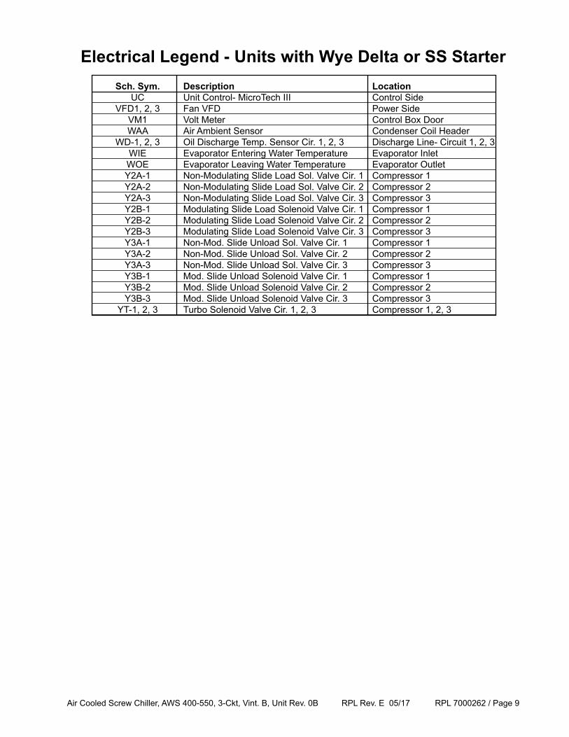
Sch. Sym. Description Location UC Unit Control- MicroTech III Control Side VFD1, 2, 3 Fan VFD Power Side VM1 Volt Meter Control Box Door WAA Air Ambient Sensor Condenser Coil Header WD-1, 2, 3 Oil Discharge Temp. Sensor Cir. 1, 2, 3 Discharge Line- Circuit 1, 2, 3 WIE Evaporator Entering Water Temperature Evaporator Inlet WOE Evaporator Leaving Water Temperature Evaporator Outlet Y2A-1 Non-Modulating Slide Load Sol. Valve Cir. 1 Compressor 1 Y2A-2 Non-Modulating Slide Load Sol. Valve Cir. 2 Compressor 2 Y2A-3 Non-Modulating Slide Load Sol. Valve Cir. 3 Compressor 3 Y2B-1 Modulating Slide Load Solenoid Valve Cir. 1 Compressor 1 Y2B-2 Modulating Slide Load Solenoid Valve Cir. 2 Compressor 2 Y2B-3 Modulating Slide Load Solenoid Valve Cir. 3 Compressor 3 Y3A-1 Non-Mod. Slide Unload Sol. Valve Cir. 1 Compressor 1 Y3A-2 Non-Mod. Slide Unload Sol. Valve Cir. 2 Compressor 2 Y3A-3 Non-Mod. Slide Unload Sol. Valve Cir. 3 Compressor 3 Y3B-1 Mod. Slide Unload Solenoid Valve Cir. 1 Compressor 1 Y3B-2 Mod. Slide Unload Solenoid Valve Cir. 2 Compressor 2 Y3B-3 Mod. Slide Unload Solenoid Valve Cir. 3 Compressor 3 YT-1, 2, 3 Turbo Solenoid Valve Cir. 1, 2, 3 Compressor 1, 2, 3
Electrical Legend - Units with Wye Delta or SS Starter
Air Cooled Screw Chiller, AWS 400-550, 3-Ckt, Vint. B, Unit Rev. 0B RPL Rev. E 05/17 RPL 7000262 / Page 10
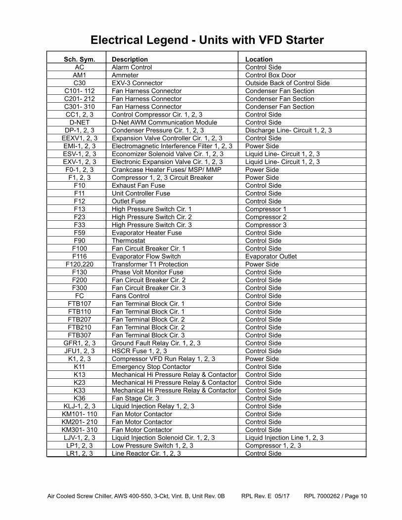
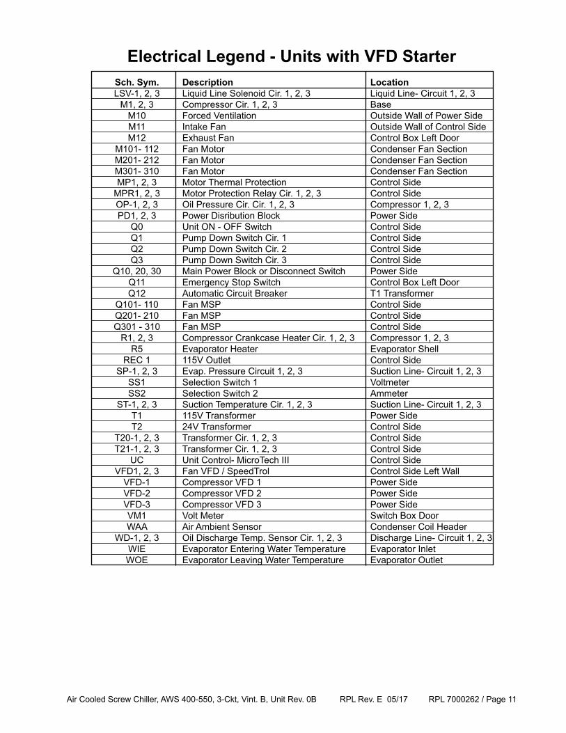
Electrical Legend - Units with VFD Starter Sch. Sym. Description Location AC Alarm Control Control Side AM1 Ammeter Control Box Door C30 EXV-3 Connector Outside Back of Control Side C101- 112 Fan Harness Connector Condenser Fan Section C201- 212 Fan Harness Connector Condenser Fan Section C301- 310 Fan Harness Connector Condenser Fan Section CC1, 2, 3 Control Compressor Cir. 1, 2, 3 Control Side D-NET D-Net AWM Communication Module Control Side DP-1, 2, 3 Condenser Pressure Cir. 1, 2, 3 Discharge Line- Circuit 1, 2, 3 EEXV1, 2, 3 Expansion Valve Controller Cir. 1, 2, 3 Control Side EMI-1, 2, 3 Electromagnetic Interference Filter 1, 2, 3 Power Side ESV-1, 2, 3 Economizer Solenoid Valve Cir. 1, 2, 3 Liquid Line- Circuit 1, 2, 3 EXV-1, 2, 3 Electronic Expansion Valve Cir. 1, 2, 3 Liquid Line- Circuit 1, 2, 3 F0-1, 2, 3 Crankcase Heater Fuses/ MSP/ MMP Power Side F1, 2, 3 Compressor 1, 2, 3 Circuit Breaker Power Side F10 Exhaust Fan Fuse Control Side F11 Unit Controller Fuse Control Side F12 Outlet Fuse Control Side F13 High Pressure Switch Cir. 1 Compressor 1 F23 High Pressure Switch Cir. 2 Compressor 2 F33 High Pressure Switch Cir. 3 Compressor 3 F59 Evaporator Heater Fuse Control Side F90 Thermostat Control Side F100 Fan Circuit Breaker Cir. 1 Control Side F116 Evaporator Flow Switch Evaporator Outlet F120,220 Transformer T1 Protection Power Side F130 Phase Volt Monitor Fuse Control Side F200 Fan Circuit Breaker Cir. 2 Control Side F300 Fan Circuit Breaker Cir. 3 Control Side FC Fans Control Control Side FTB107 Fan Terminal Block Cir. 1 Control Side FTB110 Fan Terminal Block Cir. 1 Control Side FTB207 Fan Terminal Block Cir. 2 Control Side FTB210 Fan Terminal Block Cir. 2 Control Side FTB307 Fan Terminal Block Cir. 3 Control Side GFR1, 2, 3 Ground Fault Relay Cir. 1, 2, 3 Control Side JFU1, 2, 3 HSCR Fuse 1, 2, 3 Control Side K1, 2, 3 Compressor VFD Run Relay 1, 2, 3 Power Side K11 Emergency Stop Contactor Control Side K13 Mechanical Hi Pressure Relay & Contactor Control Side K23 Mechanical Hi Pressure Relay & Contactor Control Side K33 Mechanical Hi Pressure Relay & Contactor Control Side K36 Fan Stage Cir. 3 Control Side KLJ-1, 2, 3 Liquid Injection Relay 1, 2, 3 Control Side KM101- 110 Fan Motor Contactor Control Side KM201- 210 Fan Motor Contactor Control Side KM301- 310 Fan Motor Contactor Control Side LJV-1, 2, 3 Liquid Injection Solenoid Cir. 1, 2, 3 Liquid Injection Line 1, 2, 3 LP1, 2, 3 Low Pressure Switch 1, 2, 3 Compressor 1, 2, 3 LR1, 2, 3 Line Reactor Cir. 1, 2, 3 Control Side
Air Cooled Screw Chiller, AWS 400-550, 3-Ckt, Vint. B, Unit Rev. 0B RPL Rev. E 05/17 RPL 7000262 / Page 11
Electrical Legend - Units with VFD Starter Sch. Sym. Description Location LSV-1, 2, 3 Liquid Line Solenoid Cir. 1, 2, 3 Liquid Line- Circuit 1, 2, 3 M1, 2, 3 Compressor Cir. 1, 2, 3 Base M10 Forced Ventilation Outside Wall of Power Side M11 Intake Fan Outside Wall of Control Side M12 Exhaust Fan Control Box Left Door M101- 112 Fan Motor Condenser Fan Section M201- 212 Fan Motor Condenser Fan Section M301- 310 Fan Motor Condenser Fan Section MP1, 2, 3 Motor Thermal Protection Control Side MPR1, 2, 3 Motor Protection Relay Cir. 1, 2, 3 Control Side OP-1, 2, 3 Oil Pressure Cir. Cir. 1, 2, 3 Compressor 1, 2, 3 PD1, 2, 3 Power Disribution Block Power Side Q0 Unit ON - OFF Switch Control Side Q1 Pump Down Switch Cir. 1 Control Side Q2 Pump Down Switch Cir. 2 Control Side Q3 Pump Down Switch Cir. 3 Control Side Q10, 20, 30 Main Power Block or Disconnect Switch Power Side Q11 Emergency Stop Switch Control Box Left Door Q12 Automatic Circuit Breaker T1 Transformer Q101- 110 Fan MSP Control Side Q201- 210 Fan MSP Control Side Q301 - 310 Fan MSP Control Side R1, 2, 3 Compressor Crankcase Heater Cir. 1, 2, 3 Compressor 1, 2, 3 R5 Evaporator Heater Evaporator Shell REC 1 115V Outlet Control Side SP-1, 2, 3 Evap. Pressure Circuit 1, 2, 3 Suction Line- Circuit 1, 2, 3 SS1 Selection Switch 1 Voltmeter SS2 Selection Switch 2 Ammeter ST-1, 2, 3 Suction Temperature Cir. 1, 2, 3 Suction Line- Circuit 1, 2, 3 T1 115V Transformer Power Side T2 24V Transformer Control Side T20-1, 2, 3 Transformer Cir. 1, 2, 3 Control Side T21-1, 2, 3 Transformer Cir. 1, 2, 3 Control Side UC Unit Control- MicroTech III Control Side VFD1, 2, 3 Fan VFD / SpeedTrol Control Side Left Wall VFD-1 Compressor VFD 1 Power Side VFD-2 Compressor VFD 2 Power Side VFD-3 Compressor VFD 3 Power Side VM1 Volt Meter Switch Box Door WAA Air Ambient Sensor Condenser Coil Header WD-1, 2, 3 Oil Discharge Temp. Sensor Cir. 1, 2, 3 Discharge Line- Circuit 1, 2, 3 WIE Evaporator Entering Water Temperature Evaporator Inlet WOE Evaporator Leaving Water Temperature Evaporator Outlet
Air Cooled Screw Chiller, AWS 400-550, 3-Ckt, Vint. B, Unit Rev. 0B RPL Rev. E 05/17 RPL 7000262 / Page 12
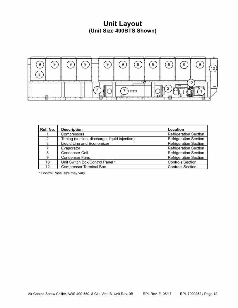
Unit Layout(Unit Size 400BTS Shown)
10
1
8
2
Ref. No. Description Location 1 Compressors Refrigeration Section 2 Tubing (suction, discharge, liquid injection) Refrigeration Section 3 Liquid Line and Economizer Refrigeration Section 7 Evaporator Refrigeration Section 8 Condenser Coil Refrigeration Section 9 Condenser Fans Refrigeration Section 10 Unit Switch Box/Control Panel * Controls Section 12 Compressor Terminal Box Controls Section
9
7
9 9 9 99 9 9
12
* Control Panel size may vary.
99 9
3
Air Cooled Screw Chiller, AWS 400-550, 3-Ckt, Vint. B, Unit Rev. 0B RPL Rev. E 05/17 RPL 7000262 / Page 13
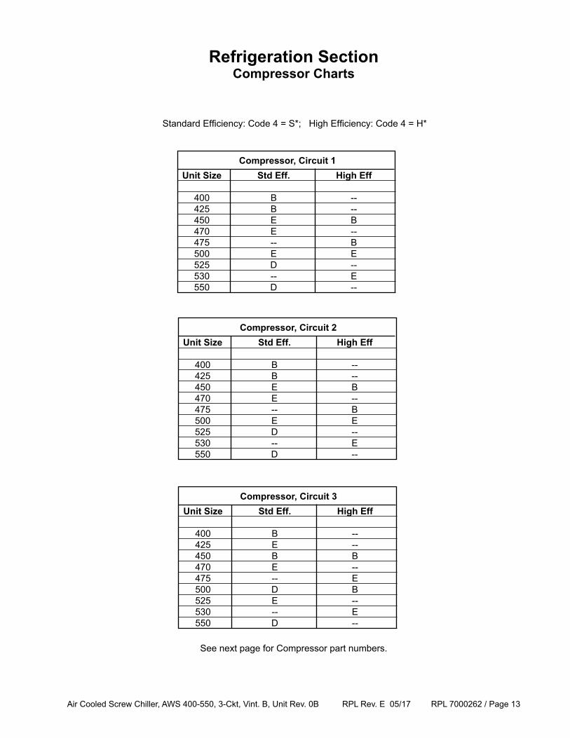
Unit Size Std Eff. High Eff 400 B -- 425 B -- 450 E B 470 E -- 475 -- B 500 E E 525 D -- 530 -- E 550 D --
Compressor, Circuit 1
Refrigeration SectionCompressor Charts
See next page for Compressor part numbers.
Standard Efficiency: Code 4 = S*; High Efficiency: Code 4 = H*
Unit Size Std Eff. High Eff 400 B -- 425 B -- 450 E B 470 E -- 475 -- B 500 E E 525 D -- 530 -- E 550 D --
Compressor, Circuit 2
Unit Size Std Eff. High Eff 400 B -- 425 E -- 450 B B 470 E -- 475 -- E 500 D B 525 E -- 530 -- E 550 D --
Compressor, Circuit 3
Air Cooled Screw Chiller, AWS 400-550, 3-Ckt, Vint. B, Unit Rev. 0B RPL Rev. E 05/17 RPL 7000262 / Page 14
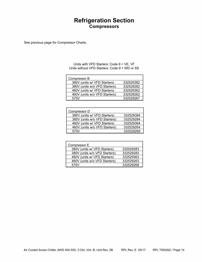
Compressor B 380V (units w/ VFD Starters) 332529382 380V (units w/o VFD Starters) 332529282 460V (units w/ VFD Starters) 332529362 460V (units w/o VFD Starters) 332529262 575V 332529267
Compressor D 380V (units w/ VFD Starters) 332529384 380V (units w/o VFD Starters) 332529284 460V (units w/ VFD Starters) 332529364 460V (units w/o VFD Starters) 332529264 575V 332529269
Compressor E 380V (units w/ VFD Starters) 332529383 380V (units w/o VFD Starters) 332529283 460V (units w/ VFD Starters) 332529363 460V (units w/o VFD Starters) 332529263 575V 332529268
Units with VFD Starters: Code 9 = VE, VFUnits without VFD Starters: Code 9 = WD or SS
Refrigeration SectionCompressors
See previous page for Compressor Charts.
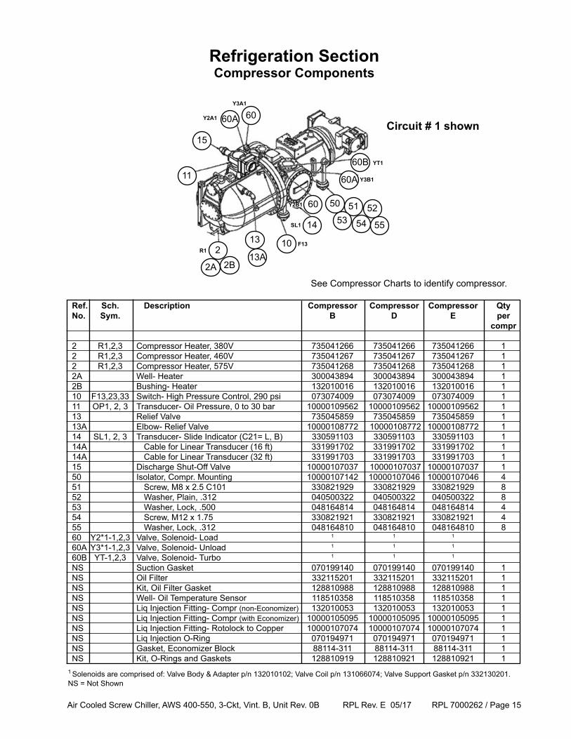
Air Cooled Screw Chiller, AWS 400-550, 3-Ckt, Vint. B, Unit Rev. 0B RPL Rev. E 05/17 RPL 7000262 / Page 15
Ref. Sch. Description Compressor Compressor Compressor Qty No. Sym. B D E per compr
2 R1,2,3 Compressor Heater, 380V 735041266 735041266 735041266 1 2 R1,2,3 Compressor Heater, 460V 735041267 735041267 735041267 1 2 R1,2,3 Compressor Heater, 575V 735041268 735041268 735041268 1 2A Well- Heater 300043894 300043894 300043894 1 2B Bushing- Heater 132010016 132010016 132010016 1 10 F13,23,33 Switch- High Pressure Control, 290 psi 073074009 073074009 073074009 1 11 OP1, 2, 3 Transducer- Oil Pressure, 0 to 30 bar 10000109562 10000109562 10000109562 1 13 Relief Valve 735045859 735045859 735045859 1 13A Elbow- Relief Valve 10000108772 10000108772 10000108772 1 14 SL1, 2, 3 Transducer- Slide Indicator (C21= L, B) 330591103 330591103 330591103 1 14A Cable for Linear Transducer (16 ft) 331991702 331991702 331991702 1 14A Cable for Linear Transducer (32 ft) 331991703 331991703 331991703 1 15 Discharge Shut-Off Valve 10000107037 10000107037 10000107037 1 50 Isolator, Compr. Mounting 10000107142 10000107046 10000107046 4 51 Screw, M8 x 2.5 C101 330821929 330821929 330821929 8 52 Washer, Plain, .312 040500322 040500322 040500322 8 53 Washer, Lock, .500 048164814 048164814 048164814 4 54 Screw, M12 x 1.75 330821921 330821921 330821921 4 55 Washer, Lock, .312 048164810 048164810 048164810 8 60 Y2*1-1,2,3 Valve, Solenoid- Load 1 1 1
60A Y3*1-1,2,3 Valve, Solenoid- Unload 1 1 1
60B YT-1,2,3 Valve, Solenoid- Turbo 1 1 1
NS Suction Gasket 070199140 070199140 070199140 1 NS Oil Filter 332115201 332115201 332115201 1 NS Kit, Oil Filter Gasket 128810988 128810988 128810988 1 NS Well- Oil Temperature Sensor 118510358 118510358 118510358 1 NS Liq Injection Fitting- Compr (non-Economizer) 132010053 132010053 132010053 1 NS Liq Injection Fitting- Compr (with Economizer) 10000105095 10000105095 10000105095 1 NS Liq Injection Fitting- Rotolock to Copper 10000107074 10000107074 10000107074 1 NS Liq Injection O-Ring 070194971 070194971 070194971 1 NS Gasket, Economizer Block 88114-311 88114-311 88114-311 1 NS Kit, O-Rings and Gaskets 128810919 128810921 128810921 1
Refrigeration SectionCompressor Components
1 Solenoids are comprised of: Valve Body & Adapter p/n 132010102; Valve Coil p/n 131066074; Valve Support Gasket p/n 332130201.NS = Not Shown
Circuit # 1 shown
10
11
213
14
5150
5352
13A
54
15
60A 60
60
60B
60A Y3B1
YT1
Y2B1
Y3A1
Y2A1
R1F13
SL1
2A 2B
See Compressor Charts to identify compressor.
55
Air Cooled Screw Chiller, AWS 400-550, 3-Ckt, Vint. B, Unit Rev. 0B RPL Rev. E 05/17 RPL 7000262 / Page 16
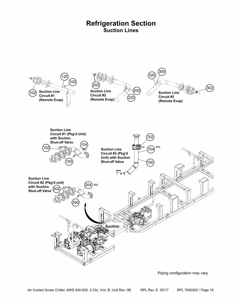
Refrigeration SectionSuction Lines
Piping configuration may vary.
Suction LineCircuit #1 (Pkg'd Unit) with SuctionShut-off Valve
102
100
104ST1
Suction
Suction LineCircuit #3 (Pkg'd Unit) with SuctionShut-off Valve
Suction LineCircuit #2 (Pkg'd unit)with SuctionShut-off Valve 202
200
204 ST2
702
700
704ST3
Suction LineCircuit #2(Remote Evap)
Suction LineCircuit #1 (Remote Evap)
Suction LineCircuit #3(Remote Evap)
120
102
100
300320
302200
220
202
Air Cooled Screw Chiller, AWS 400-550, 3-Ckt, Vint. B, Unit Rev. 0B RPL Rev. E 05/17 RPL 7000262 / Page 17
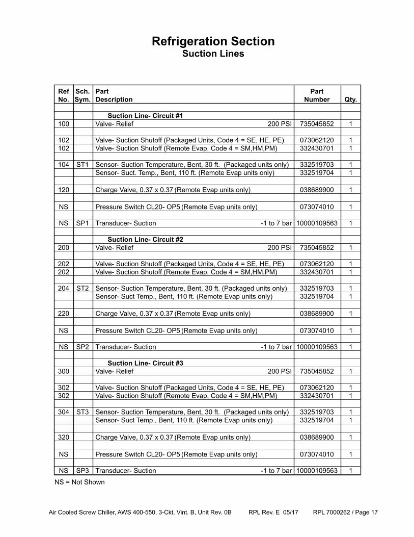
Refrigeration SectionSuction Lines
Ref Sch. Part Part No. Sym. Description Number Qty. Suction Line- Circuit #1 100 Valve- Relief 200 PSI 735045852 1
102 Valve- Suction Shutoff (Packaged Units, Code 4 = SE, HE, PE) 073062120 1 102 Valve- Suction Shutoff (Remote Evap, Code 4 = SM,HM,PM) 332430701 1
104 ST1 Sensor- Suction Temperature, Bent, 30 ft. (Packaged units only) 332519703 1 Sensor- Suct. Temp., Bent, 110 ft. (Remote Evap units only) 332519704 1
120 Charge Valve, 0.37 x 0.37 (Remote Evap units only) 038689900 1
NS Pressure Switch CL20- OP5 (Remote Evap units only) 073074010 1
NS SP1 Transducer- Suction -1 to 7 bar 10000109563 1
Suction Line- Circuit #2 200 Valve- Relief 200 PSI 735045852 1
202 Valve- Suction Shutoff (Packaged Units, Code 4 = SE, HE, PE) 073062120 1 202 Valve- Suction Shutoff (Remote Evap, Code 4 = SM,HM,PM) 332430701 1
204 ST2 Sensor- Suction Temperature, Bent, 30 ft. (Packaged units only) 332519703 1 Sensor- Suct Temp., Bent, 110 ft. (Remote Evap units only) 332519704 1
220 Charge Valve, 0.37 x 0.37 (Remote Evap units only) 038689900 1
NS Pressure Switch CL20- OP5 (Remote Evap units only) 073074010 1
NS SP2 Transducer- Suction -1 to 7 bar 10000109563 1
Suction Line- Circuit #3 300 Valve- Relief 200 PSI 735045852 1
302 Valve- Suction Shutoff (Packaged Units, Code 4 = SE, HE, PE) 073062120 1 302 Valve- Suction Shutoff (Remote Evap, Code 4 = SM,HM,PM) 332430701 1
304 ST3 Sensor- Suction Temperature, Bent, 30 ft. (Packaged units only) 332519703 1 Sensor- Suct Temp., Bent, 110 ft. (Remote Evap units only) 332519704 1
320 Charge Valve, 0.37 x 0.37 (Remote Evap units only) 038689900 1
NS Pressure Switch CL20- OP5 (Remote Evap units only) 073074010 1
NS SP3 Transducer- Suction -1 to 7 bar 10000109563 1
NS = Not Shown
Air Cooled Screw Chiller, AWS 400-550, 3-Ckt, Vint. B, Unit Rev. 0B RPL Rev. E 05/17 RPL 7000262 / Page 18
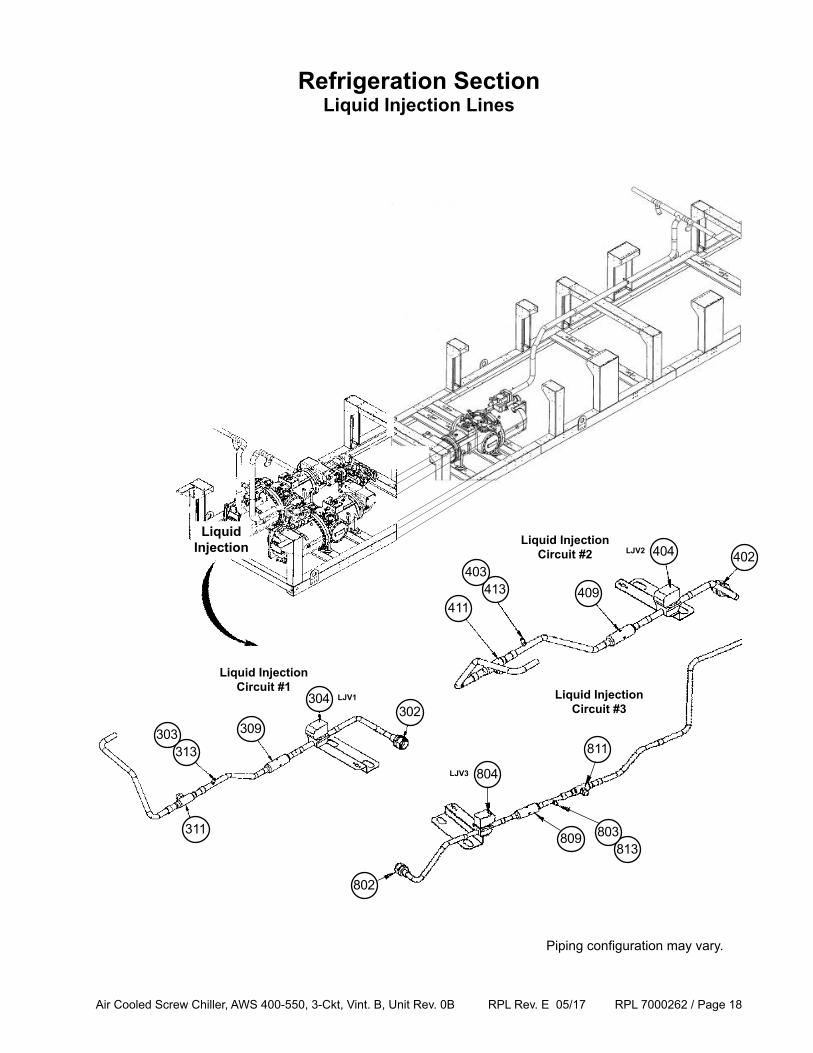
Liquid InjectionCircuit #1
Refrigeration SectionLiquid Injection Lines
311
313
309
304302
303
411413 409
404 402403
Liquid InjectionCircuit #2
LiquidInjection LJV2
LJV1 Liquid InjectionCircuit #3
811
813809
804
802
803
LJV3
Piping configuration may vary.
Air Cooled Screw Chiller, AWS 400-550, 3-Ckt, Vint. B, Unit Rev. 0B RPL Rev. E 05/17 RPL 7000262 / Page 19
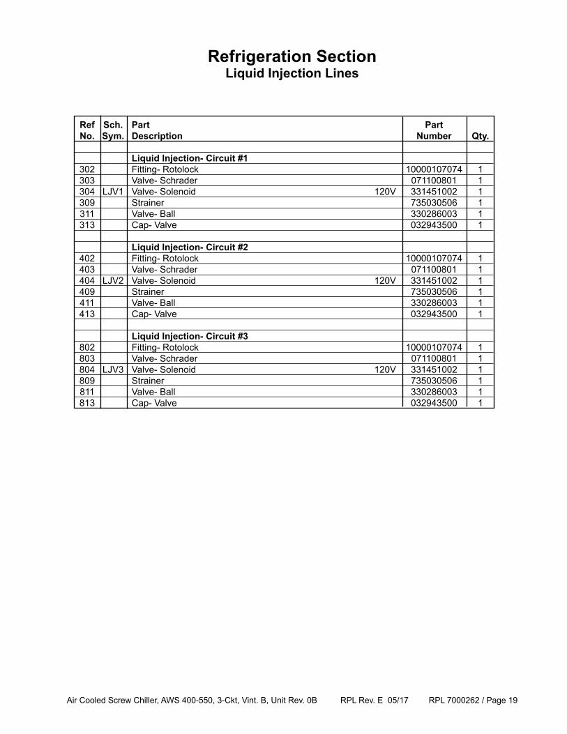
Refrigeration SectionLiquid Injection Lines
Ref Sch. Part Part No. Sym. Description Number Qty.
Liquid Injection- Circuit #1 302 Fitting- Rotolock 10000107074 1 303 Valve- Schrader 071100801 1 304 LJV1 Valve- Solenoid 120V 331451002 1 309 Strainer 735030506 1 311 Valve- Ball 330286003 1 313 Cap- Valve 032943500 1
Liquid Injection- Circuit #2 402 Fitting- Rotolock 10000107074 1 403 Valve- Schrader 071100801 1 404 LJV2 Valve- Solenoid 120V 331451002 1 409 Strainer 735030506 1 411 Valve- Ball 330286003 1 413 Cap- Valve 032943500 1
Liquid Injection- Circuit #3 802 Fitting- Rotolock 10000107074 1 803 Valve- Schrader 071100801 1 804 LJV3 Valve- Solenoid 120V 331451002 1 809 Strainer 735030506 1 811 Valve- Ball 330286003 1 813 Cap- Valve 032943500 1
Air Cooled Screw Chiller, AWS 400-550, 3-Ckt, Vint. B, Unit Rev. 0B RPL Rev. E 05/17 RPL 7000262 / Page 20
508
500501
505
504503
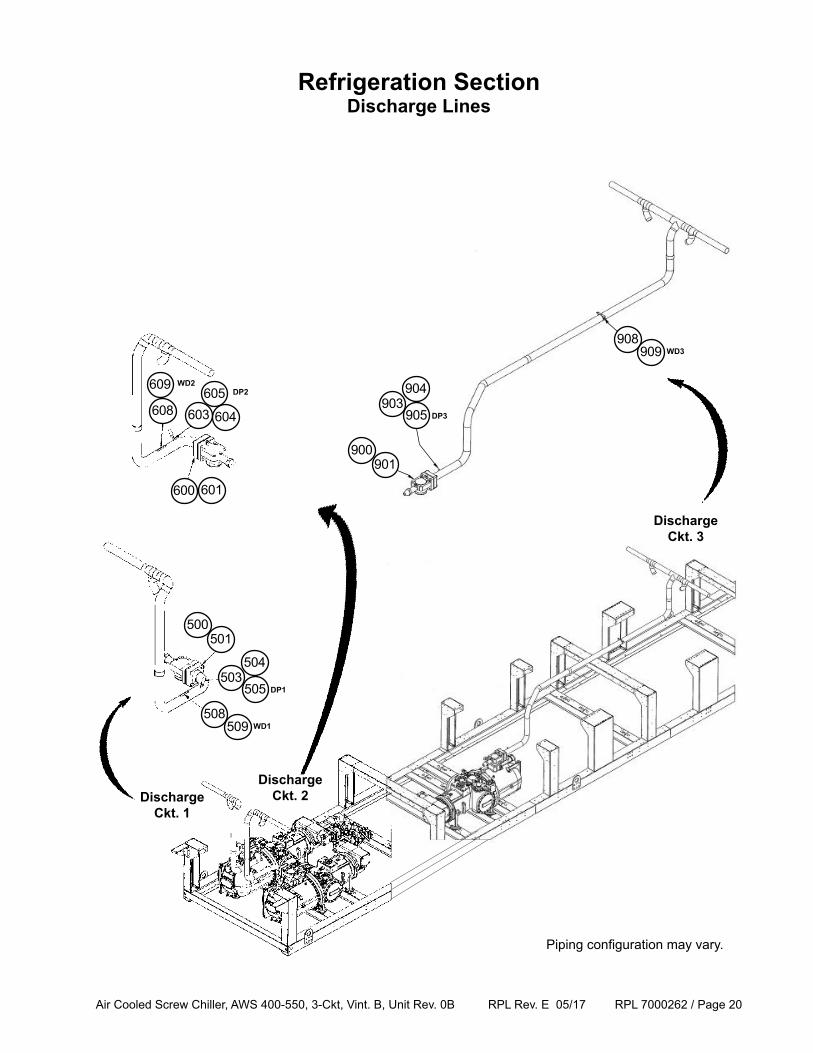
DischargeCkt. 1
509
DP1
WD1
Refrigeration SectionDischarge Lines
608605
604603
600 601
609DP2
WD2
DischargeCkt. 3
908
900901
905
904903
909
DP3
WD3
Piping configuration may vary.
DischargeCkt. 2
Air Cooled Screw Chiller, AWS 400-550, 3-Ckt, Vint. B, Unit Rev. 0B RPL Rev. E 05/17 RPL 7000262 / Page 21
Refrigeration SectionDischarge Lines
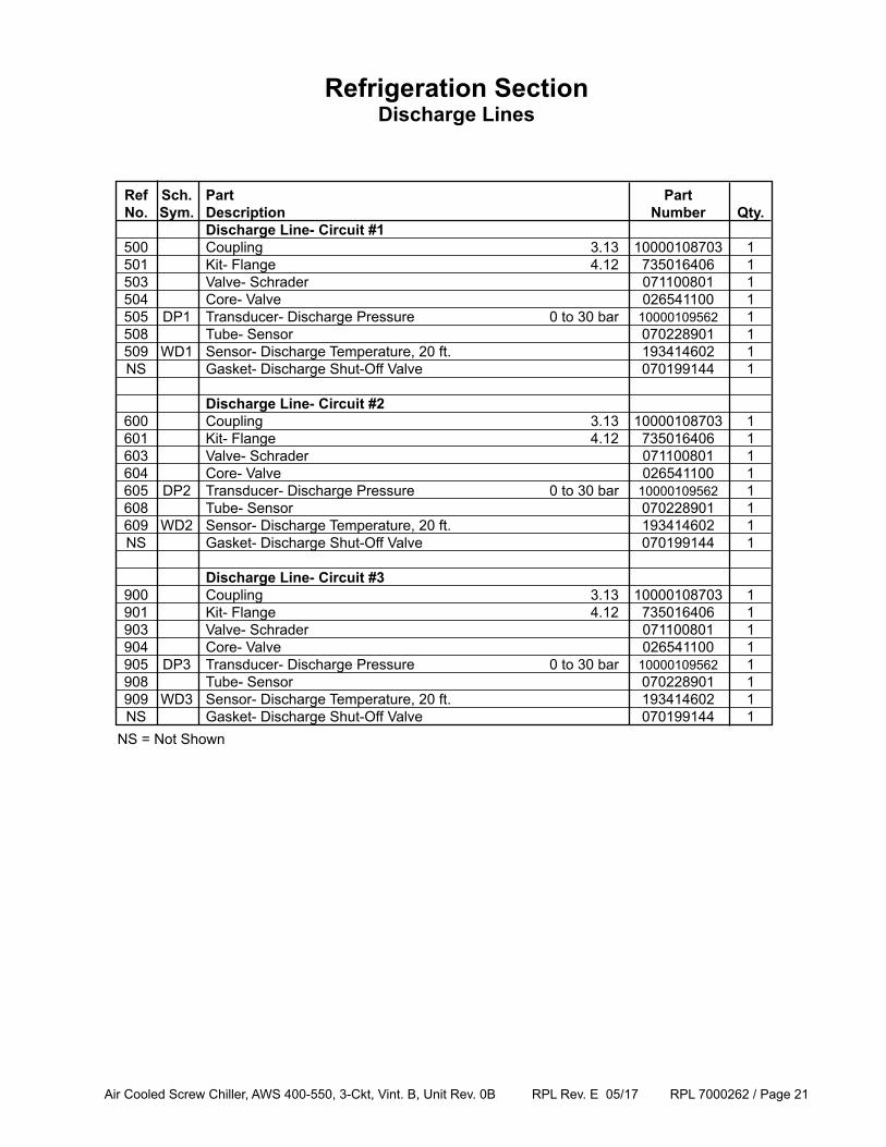
Ref Sch. Part Part No. Sym. Description Number Qty. Discharge Line- Circuit #1 500 Coupling 3.13 10000108703 1 501 Kit- Flange 4.12 735016406 1 503 Valve- Schrader 071100801 1 504 Core- Valve 026541100 1 505 DP1 Transducer- Discharge Pressure 0 to 30 bar 10000109562 1 508 Tube- Sensor 070228901 1 509 WD1 Sensor- Discharge Temperature, 20 ft. 193414602 1 NS Gasket- Discharge Shut-Off Valve 070199144 1
Discharge Line- Circuit #2 600 Coupling 3.13 10000108703 1 601 Kit- Flange 4.12 735016406 1 603 Valve- Schrader 071100801 1 604 Core- Valve 026541100 1 605 DP2 Transducer- Discharge Pressure 0 to 30 bar 10000109562 1 608 Tube- Sensor 070228901 1 609 WD2 Sensor- Discharge Temperature, 20 ft. 193414602 1 NS Gasket- Discharge Shut-Off Valve 070199144 1
Discharge Line- Circuit #3 900 Coupling 3.13 10000108703 1 901 Kit- Flange 4.12 735016406 1 903 Valve- Schrader 071100801 1 904 Core- Valve 026541100 1 905 DP3 Transducer- Discharge Pressure 0 to 30 bar 10000109562 1 908 Tube- Sensor 070228901 1 909 WD3 Sensor- Discharge Temperature, 20 ft. 193414602 1 NS Gasket- Discharge Shut-Off Valve 070199144 1NS = Not Shown
Air Cooled Screw Chiller, AWS 400-550, 3-Ckt, Vint. B, Unit Rev. 0B RPL Rev. E 05/17 RPL 7000262 / Page 22
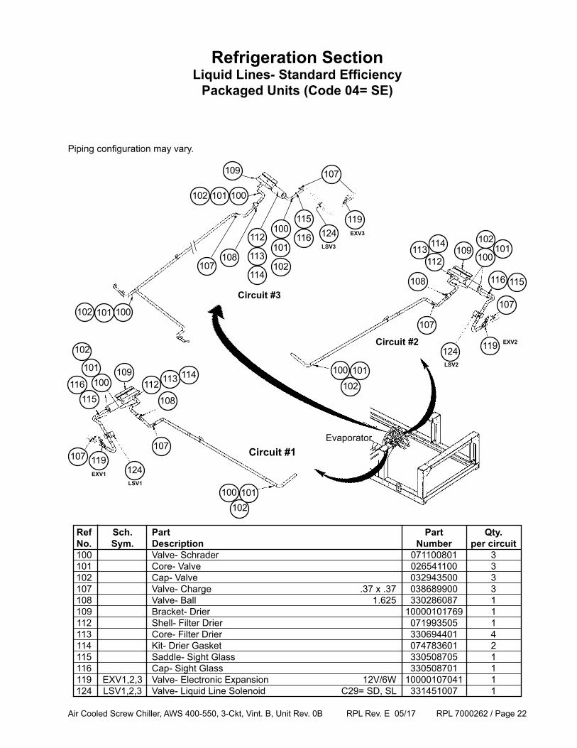
Refrigeration SectionLiquid Lines- Standard Efficiency
Packaged Units (Code 04= SE)
119
Ref Sch. Part Part Qty. No. Sym. Description Number per circuit 100 Valve- Schrader 071100801 3 101 Core- Valve 026541100 3 102 Cap- Valve 032943500 3 107 Valve- Charge .37 x .37 038689900 3 108 Valve- Ball 1.625 330286087 1 109 Bracket- Drier 10000101769 1 112 Shell- Filter Drier 071993505 1 113 Core- Filter Drier 330694401 4 114 Kit- Drier Gasket 074783601 2 115 Saddle- Sight Glass 330508705 1 116 Cap- Sight Glass 330508701 1 119 EXV1,2,3 Valve- Electronic Expansion 12V/6W 10000107041 1 124 LSV1,2,3 Valve- Liquid Line Solenoid C29= SD, SL 331451007 1
Evaporator
107 119107
124
Circuit #1
102101100
113
108
112114109
100
102
101
116115
LSV1EXV1
Piping configuration may vary.
108
107
100102 101
109
113
112
114
116
115100
102
101
Circuit #2
109100
102101
116 115
107
124
113112
114
108
107
102101100
LSV2
EXV2119
124
107
100102 101
Circuit #3
LSV3
EXV3
Air Cooled Screw Chiller, AWS 400-550, 3-Ckt, Vint. B, Unit Rev. 0B RPL Rev. E 05/17 RPL 7000262 / Page 23
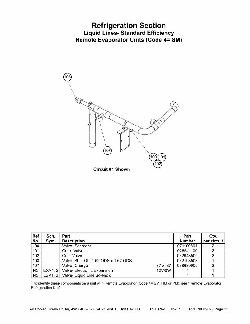
Refrigeration SectionLiquid Lines- Standard Efficiency
Remote Evaporator Units (Code 4= SM)
Ref Sch. Part Part Qty. No. Sym. Description Number per circuit 100 Valve- Schrader 071100801 2 101 Core- Valve 026541100 2 102 Cap- Valve 032943500 2 103 Valve, Shut Off, 1.62 ODS x 1.62 ODS 032193508 1 107 Valve- Charge .37 x .37 038689900 2 NS EXV1, 2 Valve- Electronic Expansion 12V/6W 3 1 NS LSV1, 2 Valve- Liquid Line Solenoid 3 13 To identify these components on a unit with Remote Evaporator (Code 4= SM, HM or PM), see "Remote Evaporator Refrigeration Kits".
102101100
107
103
Circuit #1 Shown
Air Cooled Screw Chiller, AWS 400-550, 3-Ckt, Vint. B, Unit Rev. 0B RPL Rev. E 05/17 RPL 7000262 / Page 24
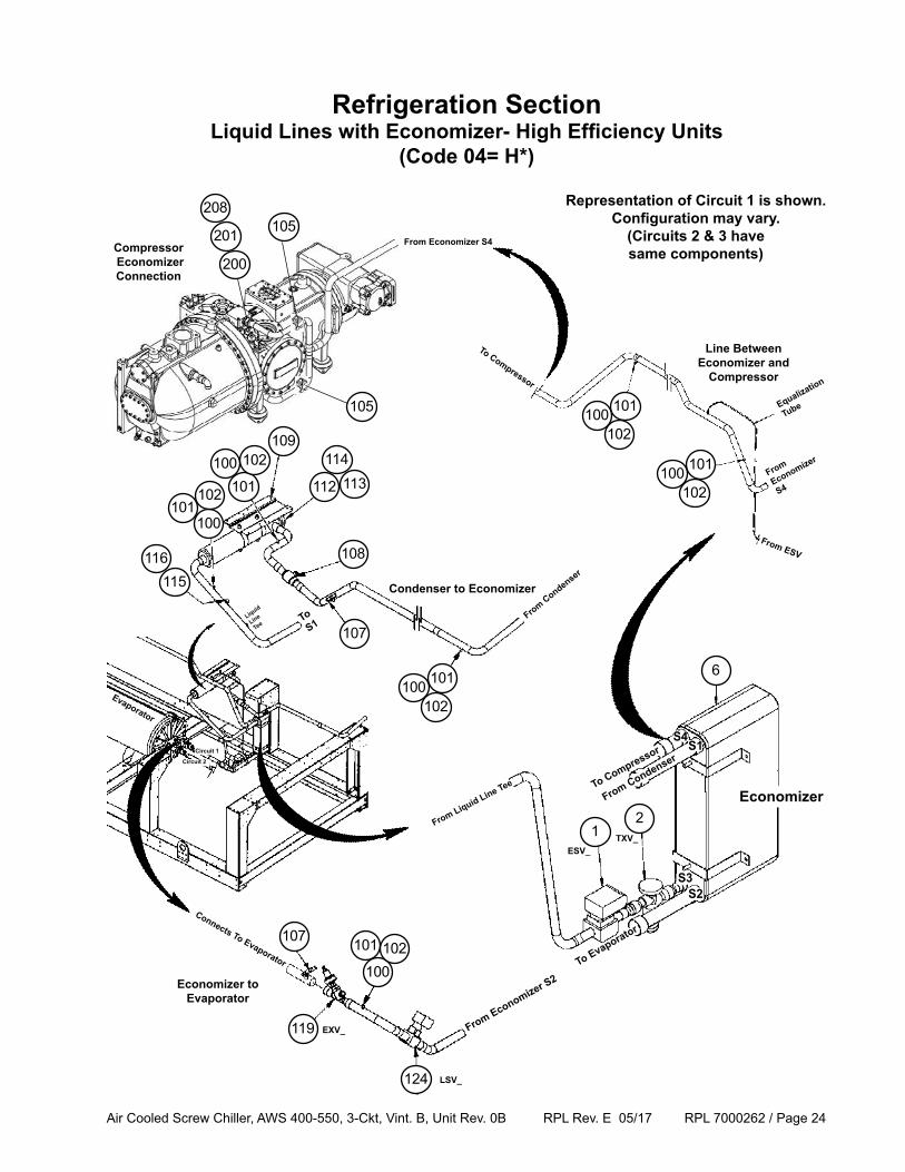
Refrigeration SectionLiquid Lines with Economizer- High Efficiency Units
(Code 04= H*)
116115
From Economizer S4
109
112101
201
200
100
102101
107
119
107
124
101
100102
21
102
101100
Line Between Economizer and
Compressor
ESV_
To Evaporator
From Economizer S2
S1S4
S2S3
Economizer
Connects To Evaporator
To S1
From Condenser
From Liquid Line Tee
Liquid
Line
Tee
To Compressor
From
Economizer
S4
To Compressor
Compressor Economizer Connection
102
101100
102
101100
From Condenser
Representation of Circuit 1 is shown.Configuration may vary.
(Circuits 2 & 3 have same components)
Condenser to Economizer
Economizer to Evaporator
Circuit 1
Circuit 2
From ESV
Equalization
Tube
Evaporator
6
100 102 114
108
113
TXV_
EXV_
LSV_
208105
105
Air Cooled Screw Chiller, AWS 400-550, 3-Ckt, Vint. B, Unit Rev. 0B RPL Rev. E 05/17 RPL 7000262 / Page 25
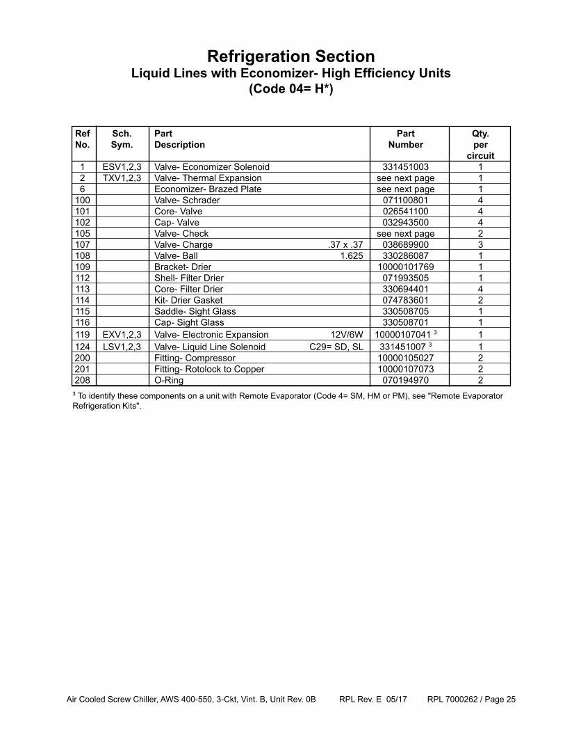
Refrigeration SectionLiquid Lines with Economizer- High Efficiency Units
(Code 04= H*)
Ref Sch. Part Part Qty. No. Sym. Description Number per circuit 1 ESV1,2,3 Valve- Economizer Solenoid 331451003 1 2 TXV1,2,3 Valve- Thermal Expansion see next page 1 6 Economizer- Brazed Plate see next page 1 100 Valve- Schrader 071100801 4 101 Core- Valve 026541100 4 102 Cap- Valve 032943500 4 105 Valve- Check see next page 2 107 Valve- Charge .37 x .37 038689900 3 108 Valve- Ball 1.625 330286087 1 109 Bracket- Drier 10000101769 1 112 Shell- Filter Drier 071993505 1 113 Core- Filter Drier 330694401 4 114 Kit- Drier Gasket 074783601 2 115 Saddle- Sight Glass 330508705 1 116 Cap- Sight Glass 330508701 1 119 EXV1,2,3 Valve- Electronic Expansion 12V/6W 10000107041 3 1 124 LSV1,2,3 Valve- Liquid Line Solenoid C29= SD, SL 331451007 3 1 200 Fitting- Compressor 10000105027 2 201 Fitting- Rotolock to Copper 10000107073 2 208 O-Ring 070194970 23 To identify these components on a unit with Remote Evaporator (Code 4= SM, HM or PM), see "Remote Evaporator Refrigeration Kits".
Air Cooled Screw Chiller, AWS 400-550, 3-Ckt, Vint. B, Unit Rev. 0B RPL Rev. E 05/17 RPL 7000262 / Page 26
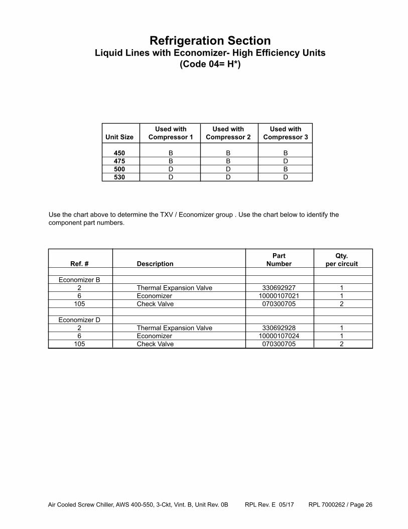
Part Qty. Ref. # Description Number per circuit
Economizer B 2 Thermal Expansion Valve 330692927 1 6 Economizer 10000107021 1 105 Check Valve 070300705 2
Economizer D 2 Thermal Expansion Valve 330692928 1 6 Economizer 10000107024 1 105 Check Valve 070300705 2
Refrigeration SectionLiquid Lines with Economizer- High Efficiency Units
(Code 04= H*)
Used with Used with Used with Unit Size Compressor 1 Compressor 2 Compressor 3 450 B B B 475 B B D 500 D D B 530 D D D
Use the chart above to determine the TXV / Economizer group . Use the chart below to identify the component part numbers.
Air Cooled Screw Chiller, AWS 400-550, 3-Ckt, Vint. B, Unit Rev. 0B RPL Rev. E 05/17 RPL 7000262 / Page 27
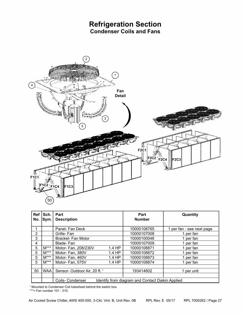
Refrigeration SectionCondenser Coils and Fans
4
2
1
3
5
Fan Detail
50
1 Mounted to Condenser Coil tubesheet behind the switch box.***= Fan number 101 - 310.
Ref Sch. Part Part Quantity No. Sym. Description Number
1 Panel- Fan Deck 10000108765 1 per fan - see next page 2 Grille- Fan 10000107008 1 per fan 3 Bracket- Fan Motor 10000100048 1 per fan 4 Blade- Fan 10000107009 1 per fan 5 M*** Motor- Fan, 208/230V 1.4 HP 10000108871 1 per fan 5 M*** Motor- Fan, 380V 1.4 HP 10000108872 1 per fan 5 M*** Motor- Fan, 460V 1.4 HP 10000108873 1 per fan 5 M*** Motor- Fan, 575V 1.4 HP 10000108874 1 per fan
50 WAA Sensor- Outdoor Air, 20 ft. 1 193414602 1 per unit
Coils- Condenser Identify from diagram and Contact Daikin Applied
F1C1
F1C2 F1C4 F1C3
F2C1
F2C2 F2C4 F2C3
Air Cooled Screw Chiller, AWS 400-550, 3-Ckt, Vint. B, Unit Rev. 0B RPL Rev. E 05/17 RPL 7000262 / Page 28
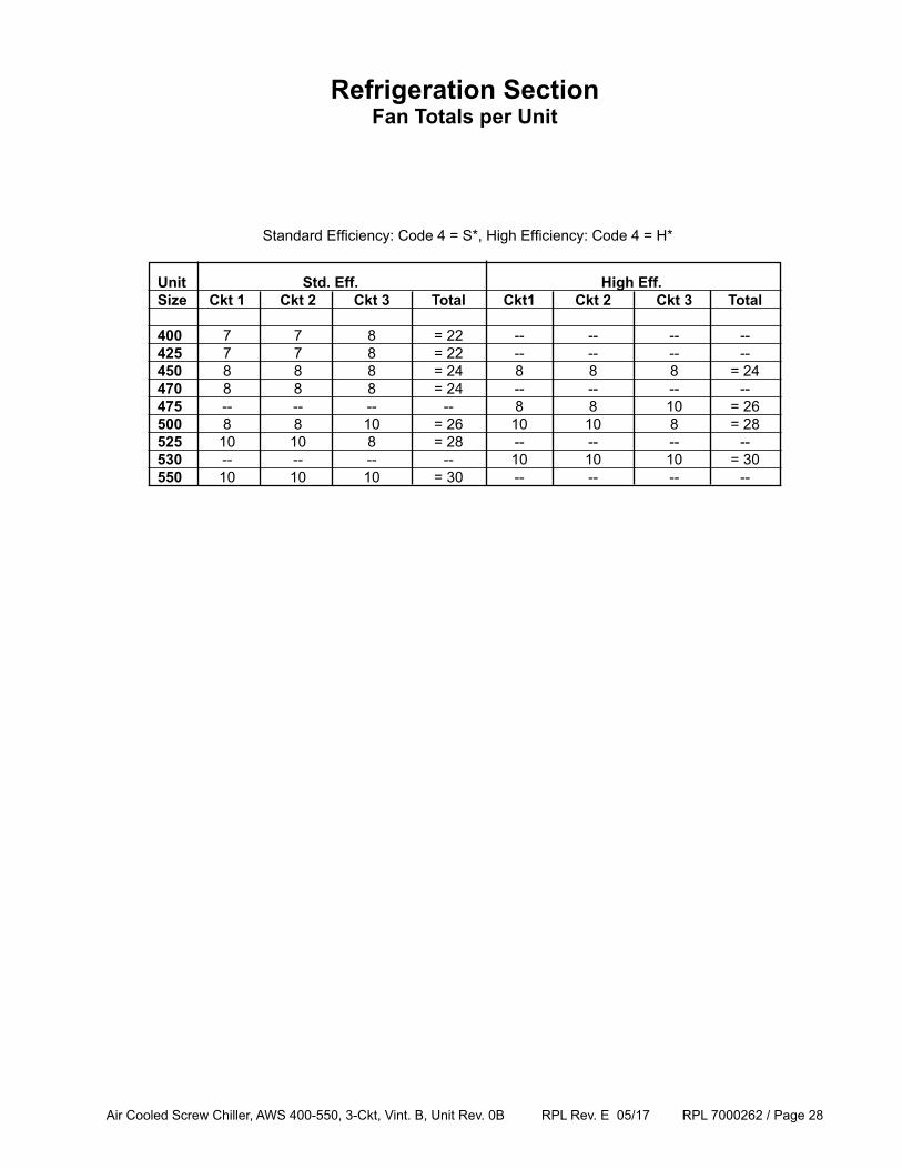
Unit Std. Eff. High Eff. Size Ckt 1 Ckt 2 Ckt 3 Total Ckt1 Ckt 2 Ckt 3 Total 400 7 7 8 = 22 -- -- -- -- 425 7 7 8 = 22 -- -- -- -- 450 8 8 8 = 24 8 8 8 = 24 470 8 8 8 = 24 -- -- -- -- 475 -- -- -- -- 8 8 10 = 26 500 8 8 10 = 26 10 10 8 = 28 525 10 10 8 = 28 -- -- -- -- 530 -- -- -- -- 10 10 10 = 30 550 10 10 10 = 30 -- -- -- --
Refrigeration SectionFan Totals per Unit
Standard Efficiency: Code 4 = S*, High Efficiency: Code 4 = H*
Air Cooled Screw Chiller, AWS 400-550, 3-Ckt, Vint. B, Unit Rev. 0B RPL Rev. E 05/17 RPL 7000262 / Page 29
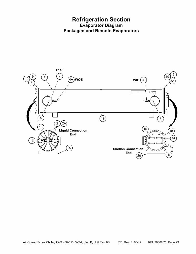
Refrigeration SectionEvaporator Diagram
Packaged and Remote Evaporators
1
5
4A 47
8
6
5
WOE WIE
F116
218
20
12
2A
109
Liquid Connection End
Suction Connection End
20
14
15 18
19
8A10
9
Air Cooled Screw Chiller, AWS 400-550, 3-Ckt, Vint. B, Unit Rev. 0B RPL Rev. E 05/17 RPL 7000262 / Page 30
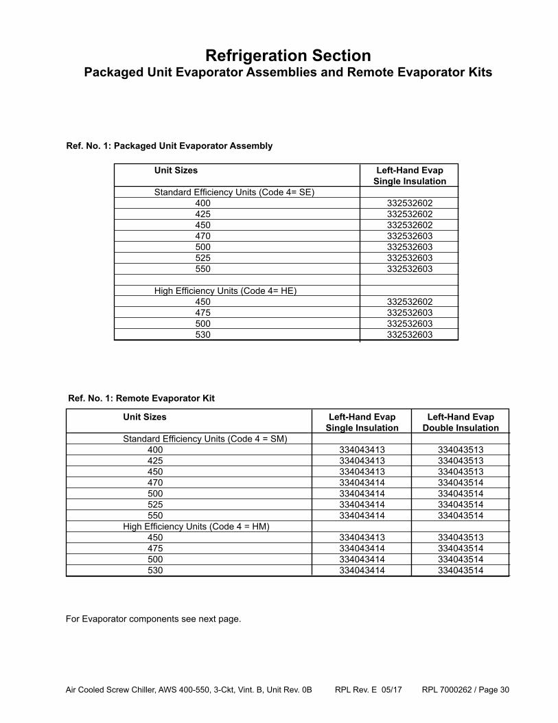
Unit Sizes Left-Hand Evap Single Insulation Standard Efficiency Units (Code 4= SE) 400 332532602 425 332532602 450 332532602 470 332532603 500 332532603 525 332532603 550 332532603
High Efficiency Units (Code 4= HE) 450 332532602 475 332532603 500 332532603 530 332532603
Refrigeration SectionPackaged Unit Evaporator Assemblies and Remote Evaporator Kits
Ref. No. 1: Packaged Unit Evaporator Assembly
For Evaporator components see next page.
Unit Sizes Left-Hand Evap Left-Hand Evap Single Insulation Double Insulation Standard Efficiency Units (Code 4 = SM) 400 334043413 334043513 425 334043413 334043513 450 334043413 334043513 470 334043414 334043514 500 334043414 334043514 525 334043414 334043514 550 334043414 334043514 High Efficiency Units (Code 4 = HM) 450 334043413 334043513 475 334043414 334043514 500 334043414 334043514 530 334043414 334043514
Ref. No. 1: Remote Evaporator Kit
Air Cooled Screw Chiller, AWS 400-550, 3-Ckt, Vint. B, Unit Rev. 0B RPL Rev. E 05/17 RPL 7000262 / Page 31
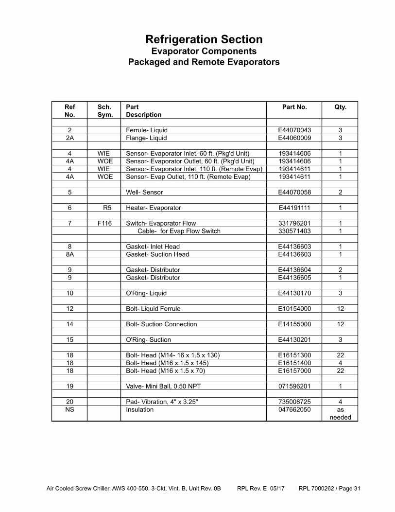
Refrigeration SectionEvaporator Components
Packaged and Remote Evaporators
Ref Sch. Part Part No. Qty. No. Sym. Description
2 Ferrule- Liquid E44070043 3 2A Flange- Liquid E44060009 3
4 WIE Sensor- Evaporator Inlet, 60 ft. (Pkg'd Unit) 193414606 1 4A WOE Sensor- Evaporator Outlet, 60 ft. (Pkg'd Unit) 193414606 1 4 WIE Sensor- Evaporator Inlet, 110 ft. (Remote Evap) 193414611 1 4A WOE Sensor- Evap Outlet, 110 ft. (Remote Evap) 193414611 1
5 Well- Sensor E44070058 2
6 R5 Heater- Evaporator E44191111 1 7 F116 Switch- Evaporator Flow 331796201 1 Cable- for Evap Flow Switch 330571403 1
8 Gasket- Inlet Head E44136603 1 8A Gasket- Suction Head E44136603 1
9 Gasket- Distributor E44136604 2 9 Gasket- Distributor E44136605 1
10 O'Ring- Liquid E44130170 3
12 Bolt- Liquid Ferrule E10154000 12
14 Bolt- Suction Connection E14155000 12
15 O'Ring- Suction E44130201 3
18 Bolt- Head (M14- 16 x 1.5 x 130) E16151300 22 18 Bolt- Head (M16 x 1.5 x 145) E16151400 4 18 Bolt- Head (M16 x 1.5 x 70) E16157000 22
19 Valve- Mini Ball, 0.50 NPT 071596201 1
20 Pad- Vibration, 4" x 3.25" 735008725 4 NS Insulation 047662050 as needed
Air Cooled Screw Chiller, AWS 400-550, 3-Ckt, Vint. B, Unit Rev. 0B RPL Rev. E 05/17 RPL 7000262 / Page 32
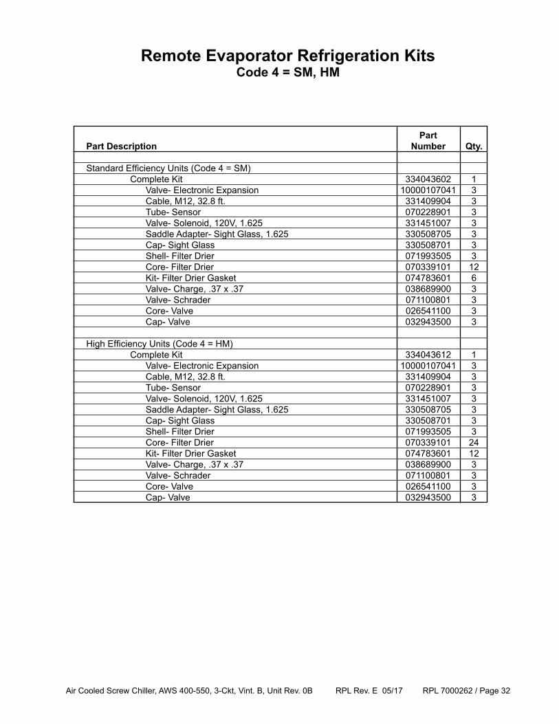
Remote Evaporator Refrigeration KitsCode 4 = SM, HM
Part Part Description Number Qty. Standard Efficiency Units (Code 4 = SM) Complete Kit 334043602 1 Valve- Electronic Expansion 10000107041 3 Cable, M12, 32.8 ft. 331409904 3 Tube- Sensor 070228901 3 Valve- Solenoid, 120V, 1.625 331451007 3 Saddle Adapter- Sight Glass, 1.625 330508705 3 Cap- Sight Glass 330508701 3 Shell- Filter Drier 071993505 3 Core- Filter Drier 070339101 12 Kit- Filter Drier Gasket 074783601 6 Valve- Charge, .37 x .37 038689900 3 Valve- Schrader 071100801 3 Core- Valve 026541100 3 Cap- Valve 032943500 3
High Efficiency Units (Code 4 = HM) Complete Kit 334043612 1 Valve- Electronic Expansion 10000107041 3 Cable, M12, 32.8 ft. 331409904 3 Tube- Sensor 070228901 3 Valve- Solenoid, 120V, 1.625 331451007 3 Saddle Adapter- Sight Glass, 1.625 330508705 3 Cap- Sight Glass 330508701 3 Shell- Filter Drier 071993505 3 Core- Filter Drier 070339101 24 Kit- Filter Drier Gasket 074783601 12 Valve- Charge, .37 x .37 038689900 3 Valve- Schrader 071100801 3 Core- Valve 026541100 3 Cap- Valve 032943500 3
Air Cooled Screw Chiller, AWS 400-550, 3-Ckt, Vint. B, Unit Rev. 0B RPL Rev. E 05/17 RPL 7000262 / Page 33
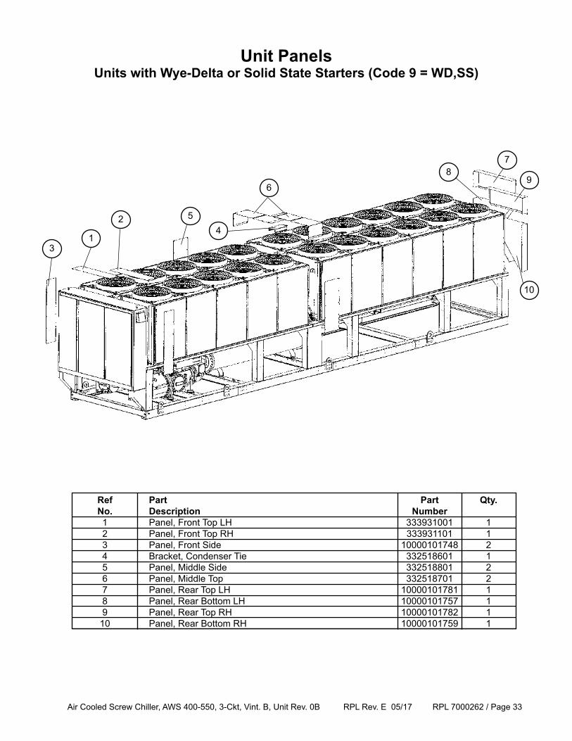
Unit PanelsUnits with Wye-Delta or Solid State Starters (Code 9 = WD,SS)
Ref Part Part Qty. No. Description Number 1 Panel, Front Top LH 333931001 1 2 Panel, Front Top RH 333931101 1 3 Panel, Front Side 10000101748 2 4 Bracket, Condenser Tie 332518601 1 5 Panel, Middle Side 332518801 2 6 Panel, Middle Top 332518701 2 7 Panel, Rear Top LH 10000101781 1 8 Panel, Rear Bottom LH 10000101757 1 9 Panel, Rear Top RH 10000101782 1 10 Panel, Rear Bottom RH 10000101759 1
1
2
3
45
6
78
9
10
Air Cooled Screw Chiller, AWS 400-550, 3-Ckt, Vint. B, Unit Rev. 0B RPL Rev. E 05/17 RPL 7000262 / Page 34
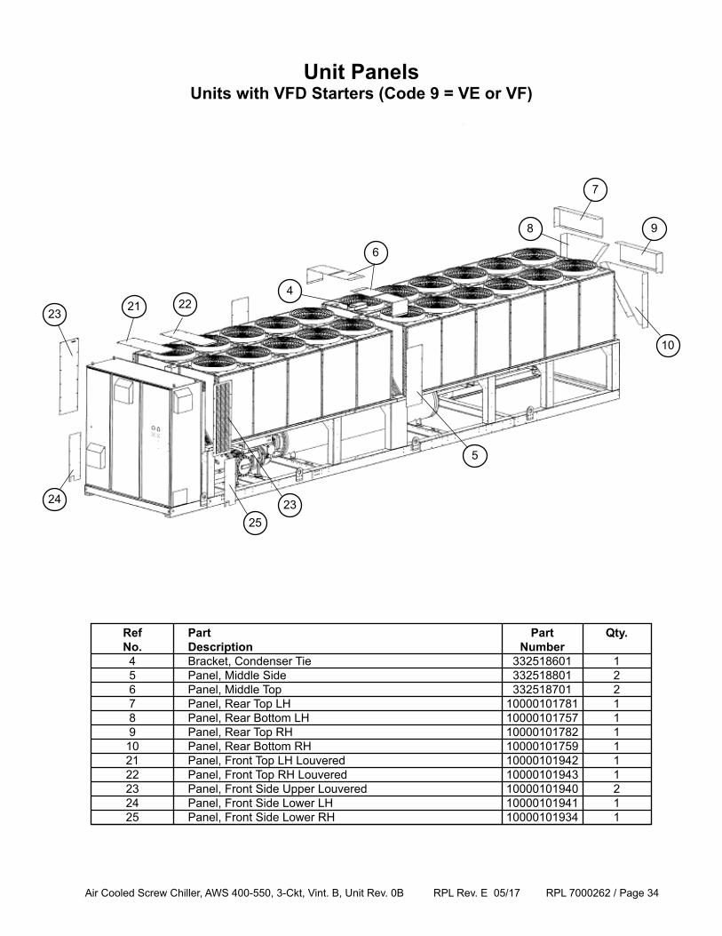
Unit PanelsUnits with VFD Starters (Code 9 = VE or VF)
Ref Part Part Qty. No. Description Number 4 Bracket, Condenser Tie 332518601 1 5 Panel, Middle Side 332518801 2 6 Panel, Middle Top 332518701 2 7 Panel, Rear Top LH 10000101781 1 8 Panel, Rear Bottom LH 10000101757 1 9 Panel, Rear Top RH 10000101782 1 10 Panel, Rear Bottom RH 10000101759 1 21 Panel, Front Top LH Louvered 10000101942 1 22 Panel, Front Top RH Louvered 10000101943 1 23 Panel, Front Side Upper Louvered 10000101940 2 24 Panel, Front Side Lower LH 10000101941 1 25 Panel, Front Side Lower RH 10000101934 1
9
10
21 22
23
4
5
6
7
8
24
25
23
Air Cooled Screw Chiller, AWS 400-550, 3-Ckt, Vint. B, Unit Rev. 0B RPL Rev. E 05/17 RPL 7000262 / Page 35
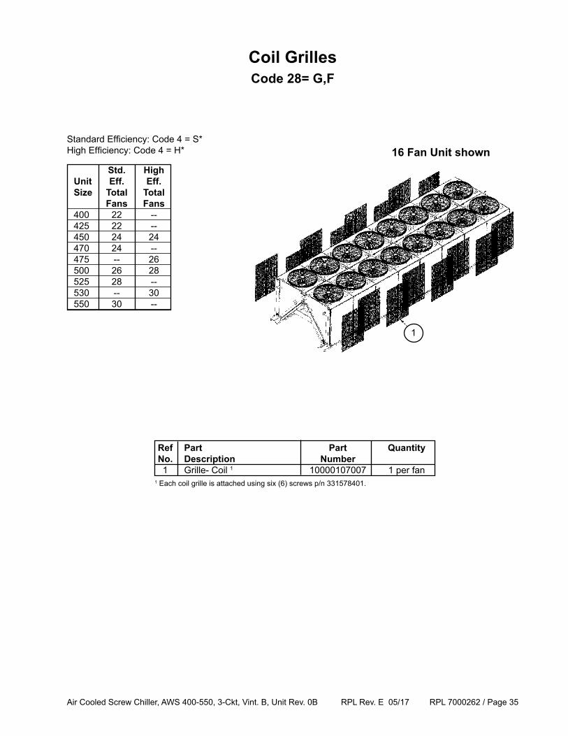
16 Fan Unit shown
1
Ref Part Part Quantity No. Description Number 1 Grille- Coil 1 10000107007 1 per fan1 Each coil grille is attached using six (6) screws p/n 331578401.
Std. High Unit Eff. Eff. Size Total Total Fans Fans 400 22 -- 425 22 -- 450 24 24 470 24 -- 475 -- 26 500 26 28 525 28 -- 530 -- 30 550 30 --
Standard Efficiency: Code 4 = S*High Efficiency: Code 4 = H*
Coil GrillesCode 28= G,F
Air Cooled Screw Chiller, AWS 400-550, 3-Ckt, Vint. B, Unit Rev. 0B RPL Rev. E 05/17 RPL 7000262 / Page 36
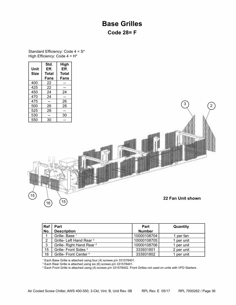
22 Fan Unit shown
Ref Part Part Quantity No. Description Number 1 Grille- Base 1 10000108704 1 per fan 2 Grille- Left Hand Rear 2 10000108705 1 per unit 3 Grille- Right Hand Rear 2 10000108706 1 per unit 15 Grille- Front Sides 4 333931801 2 per unit 16 Grille- Front Center 4 333931802 1 per unit
3
1
2
1 Each Base Grille is attached using four (4) screws p/n 331578401.2 Each Rear Grille is attached using six (6) screws p/n 331578401. 4 Each Front Grille is attached using (4) screws p/n 331578402. Front Grilles not used on units with VFD Starters.
Base GrillesCode 28= F
15
16 15
Std. High Unit Eff. Eff. Size Total Total Fans Fans 400 22 -- 425 22 -- 450 24 24 470 24 -- 475 -- 26 500 26 28 525 28 -- 530 -- 30 550 30 --
Standard Efficiency: Code 4 = S*High Efficiency: Code 4 = H*
Air Cooled Screw Chiller, AWS 400-550, 3-Ckt, Vint. B, Unit Rev. 0B RPL Rev. E 05/17 RPL 7000262 / Page 37
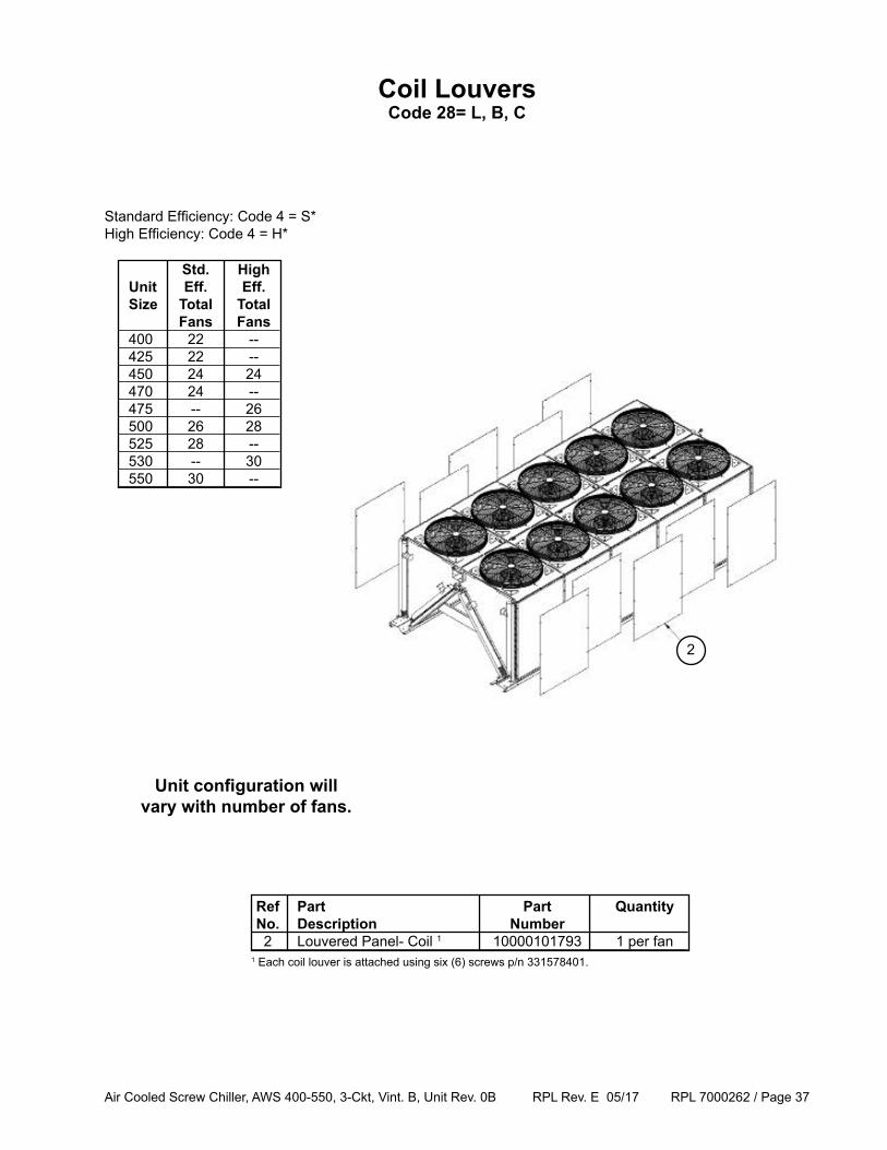
Coil LouversCode 28= L, B, C
Unit configuration will vary with number of fans.
Ref Part Part Quantity No. Description Number 2 Louvered Panel- Coil 1 10000101793 1 per fan
2
1 Each coil louver is attached using six (6) screws p/n 331578401.
Standard Efficiency: Code 4 = S*High Efficiency: Code 4 = H*
Std. High Unit Eff. Eff. Size Total Total Fans Fans 400 22 -- 425 22 -- 450 24 24 470 24 -- 475 -- 26 500 26 28 525 28 -- 530 -- 30 550 30 --
Air Cooled Screw Chiller, AWS 400-550, 3-Ckt, Vint. B, Unit Rev. 0B RPL Rev. E 05/17 RPL 7000262 / Page 38
6
4
5 64 5 3
2
4
46
5
5
6
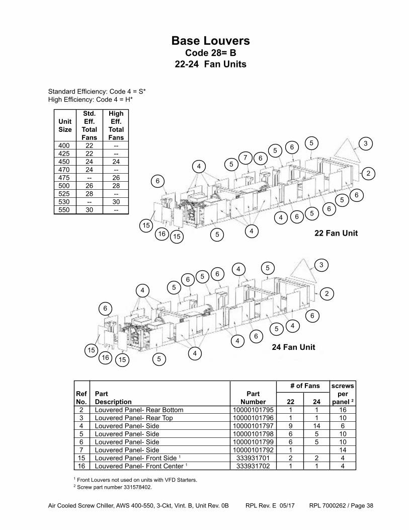
Base LouversCode 28= B
22-24 Fan Units
3
42
5 6
6
5
65
5
4
5
6
4
56
6
151615
151615
22 Fan Unit
24 Fan Unit
# of Fans screws Ref Part Part per No. Description Number 22 24 panel 2
2 Louvered Panel- Rear Bottom 10000101795 1 1 16 3 Louvered Panel- Rear Top 10000101796 1 1 10 4 Louvered Panel- Side 10000101797 9 14 6 5 Louvered Panel- Side 10000101798 6 5 10 6 Louvered Panel- Side 10000101799 6 5 10 7 Louvered Panel- Side 10000101792 1 14 15 Louvered Panel- Front Side 1 333931701 2 2 4 16 Louvered Panel- Front Center 1 333931702 1 1 4
1 Front Louvers not used on units with VFD Starters. 2 Screw part number 331578402.
Standard Efficiency: Code 4 = S*High Efficiency: Code 4 = H*
7
56
4
Std. High Unit Eff. Eff. Size Total Total Fans Fans 400 22 -- 425 22 -- 450 24 24 470 24 -- 475 -- 26 500 26 28 525 28 -- 530 -- 30 550 30 --
Air Cooled Screw Chiller, AWS 400-550, 3-Ckt, Vint. B, Unit Rev. 0B RPL Rev. E 05/17 RPL 7000262 / Page 39
6
45
64 5
3
2
4
46
5
5
6
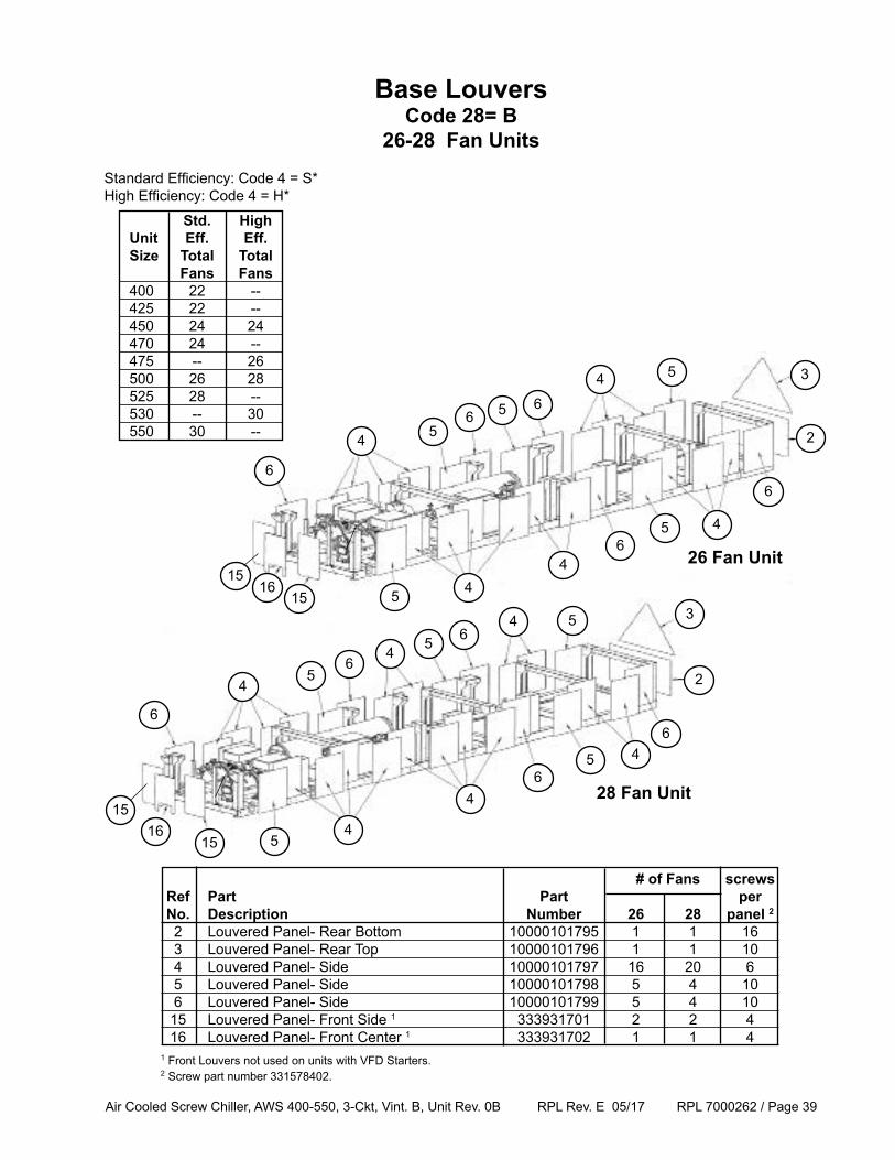
Base LouversCode 28= B
26-28 Fan Units
3
4 2
4
5
6
5
65
6
5
4
45
6
1516
15
1516
15
26 Fan Unit
28 Fan Unit
# of Fans screws Ref Part Part per No. Description Number 26 28 panel 2
2 Louvered Panel- Rear Bottom 10000101795 1 1 16 3 Louvered Panel- Rear Top 10000101796 1 1 10 4 Louvered Panel- Side 10000101797 16 20 6 5 Louvered Panel- Side 10000101798 5 4 10 6 Louvered Panel- Side 10000101799 5 4 10 15 Louvered Panel- Front Side 1 333931701 2 2 4 16 Louvered Panel- Front Center 1 333931702 1 1 41 Front Louvers not used on units with VFD Starters. 2 Screw part number 331578402.
Standard Efficiency: Code 4 = S*High Efficiency: Code 4 = H*
4
6
4
64 5
Std. High Unit Eff. Eff. Size Total Total Fans Fans 400 22 -- 425 22 -- 450 24 24 470 24 -- 475 -- 26 500 26 28 525 28 -- 530 -- 30 550 30 --
Air Cooled Screw Chiller, AWS 400-550, 3-Ckt, Vint. B, Unit Rev. 0B RPL Rev. E 05/17 RPL 7000262 / Page 40
6
4 56 4
5
3
2
4
46 5
5
6
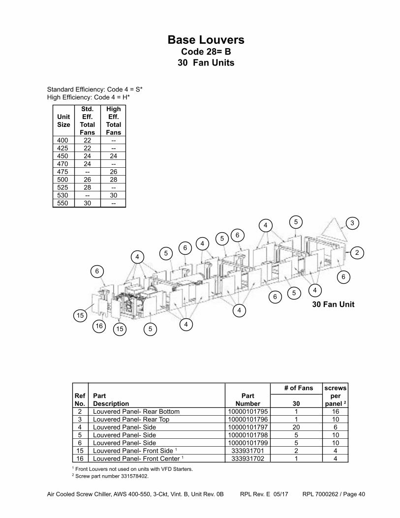
Base LouversCode 28= B
30 Fan Units
151615
30 Fan Unit
# of Fans screws Ref Part Part per No. Description Number 30 panel 2
2 Louvered Panel- Rear Bottom 10000101795 1 16 3 Louvered Panel- Rear Top 10000101796 1 10 4 Louvered Panel- Side 10000101797 20 6 5 Louvered Panel- Side 10000101798 5 10 6 Louvered Panel- Side 10000101799 5 10 15 Louvered Panel- Front Side 1 333931701 2 4 16 Louvered Panel- Front Center 1 333931702 1 41 Front Louvers not used on units with VFD Starters. 2 Screw part number 331578402.
Standard Efficiency: Code 4 = S*High Efficiency: Code 4 = H*
4
64 5
Std. High Unit Eff. Eff. Size Total Total Fans Fans 400 22 -- 425 22 -- 450 24 24 470 24 -- 475 -- 26 500 26 28 525 28 -- 530 -- 30 550 30 --
Air Cooled Screw Chiller, AWS 400-550, 3-Ckt, Vint. B, Unit Rev. 0B RPL Rev. E 05/17 RPL 7000262 / Page 41
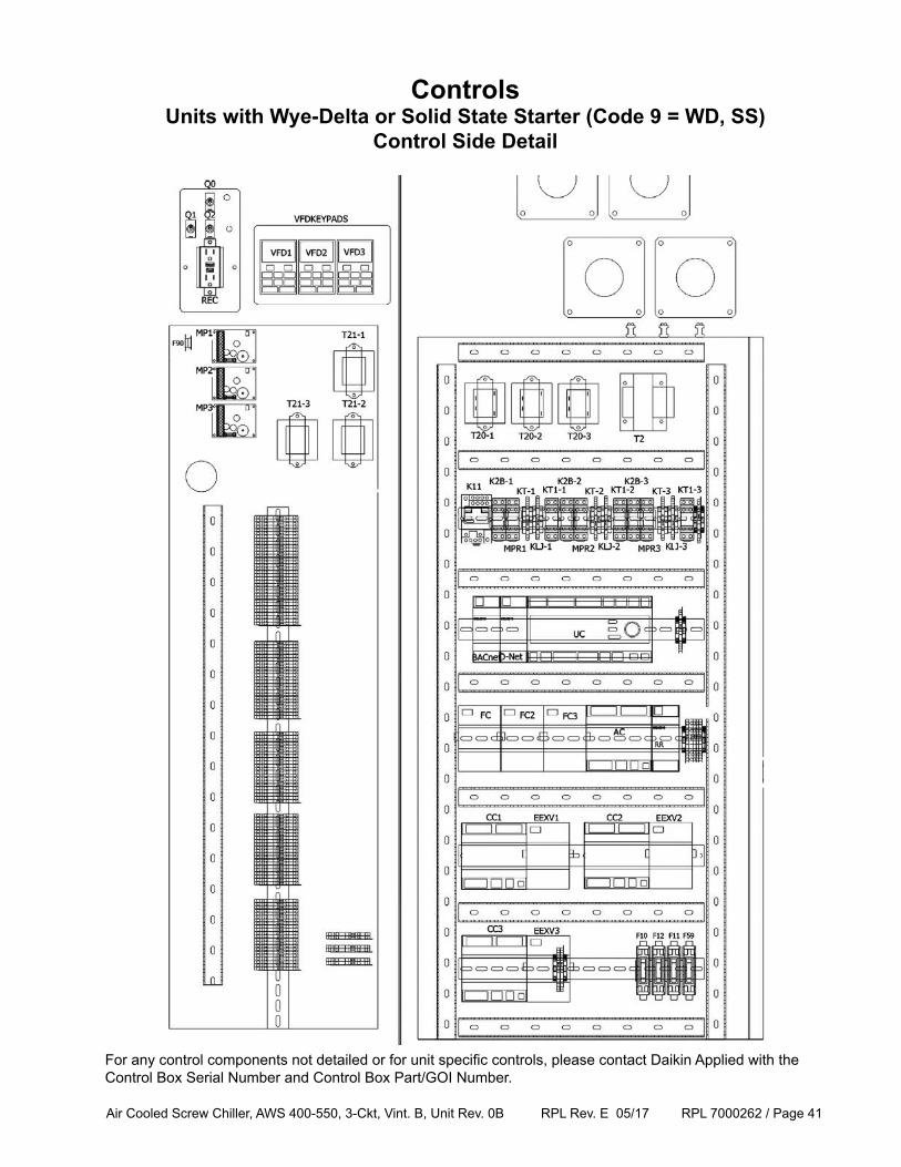
ControlsUnits with Wye-Delta or Solid State Starter (Code 9 = WD, SS)
Control Side Detail
For any control components not detailed or for unit specific controls, please contact Daikin Applied with the Control Box Serial Number and Control Box Part/GOI Number.
Air Cooled Screw Chiller, AWS 400-550, 3-Ckt, Vint. B, Unit Rev. 0B RPL Rev. E 05/17 RPL 7000262 / Page 42
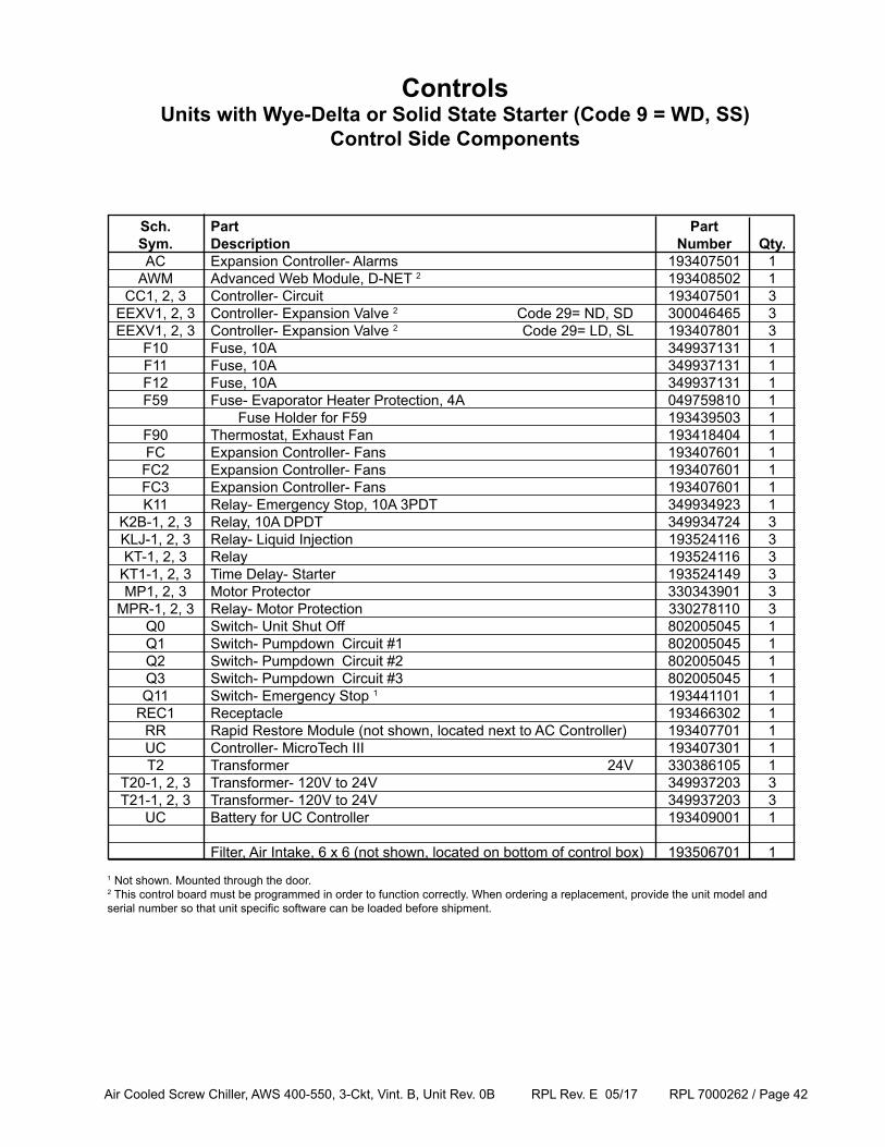
Sch. Part Part Sym. Description Number Qty. AC Expansion Controller- Alarms 193407501 1 AWM Advanced Web Module, D-NET 2 193408502 1 CC1, 2, 3 Controller- Circuit 193407501 3 EEXV1, 2, 3 Controller- Expansion Valve 2 Code 29= ND, SD 300046465 3 EEXV1, 2, 3 Controller- Expansion Valve 2 Code 29= LD, SL 193407801 3 F10 Fuse, 10A 349937131 1 F11 Fuse, 10A 349937131 1 F12 Fuse, 10A 349937131 1 F59 Fuse- Evaporator Heater Protection, 4A 049759810 1 Fuse Holder for F59 193439503 1 F90 Thermostat, Exhaust Fan 193418404 1 FC Expansion Controller- Fans 193407601 1 FC2 Expansion Controller- Fans 193407601 1 FC3 Expansion Controller- Fans 193407601 1 K11 Relay- Emergency Stop, 10A 3PDT 349934923 1 K2B-1, 2, 3 Relay, 10A DPDT 349934724 3 KLJ-1, 2, 3 Relay- Liquid Injection 193524116 3 KT-1, 2, 3 Relay 193524116 3 KT1-1, 2, 3 Time Delay- Starter 193524149 3 MP1, 2, 3 Motor Protector 330343901 3 MPR-1, 2, 3 Relay- Motor Protection 330278110 3 Q0 Switch- Unit Shut Off 802005045 1 Q1 Switch- Pumpdown Circuit #1 802005045 1 Q2 Switch- Pumpdown Circuit #2 802005045 1 Q3 Switch- Pumpdown Circuit #3 802005045 1 Q11 Switch- Emergency Stop 1 193441101 1 REC1 Receptacle 193466302 1 RR Rapid Restore Module (not shown, located next to AC Controller) 193407701 1 UC Controller- MicroTech III 193407301 1 T2 Transformer 24V 330386105 1 T20-1, 2, 3 Transformer- 120V to 24V 349937203 3 T21-1, 2, 3 Transformer- 120V to 24V 349937203 3 UC Battery for UC Controller 193409001 1
Filter, Air Intake, 6 x 6 (not shown, located on bottom of control box) 193506701 1
ControlsUnits with Wye-Delta or Solid State Starter (Code 9 = WD, SS)
Control Side Components
1 Not shown. Mounted through the door.2 This control board must be programmed in order to function correctly. When ordering a replacement, provide the unit model and serial number so that unit specific software can be loaded before shipment.
Air Cooled Screw Chiller, AWS 400-550, 3-Ckt, Vint. B, Unit Rev. 0B RPL Rev. E 05/17 RPL 7000262 / Page 43
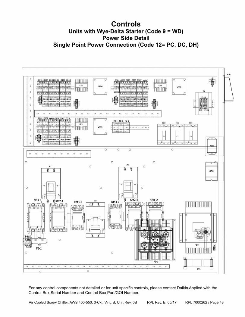
ControlsUnits with Wye-Delta Starter (Code 9 = WD)
Power Side DetailSingle Point Power Connection (Code 12= PC, DC, DH)
For any control components not detailed or for unit specific controls, please contact Daikin Applied with the Control Box Serial Number and Control Box Part/GOI Number.
Air Cooled Screw Chiller, AWS 400-550, 3-Ckt, Vint. B, Unit Rev. 0B RPL Rev. E 05/17 RPL 7000262 / Page 44
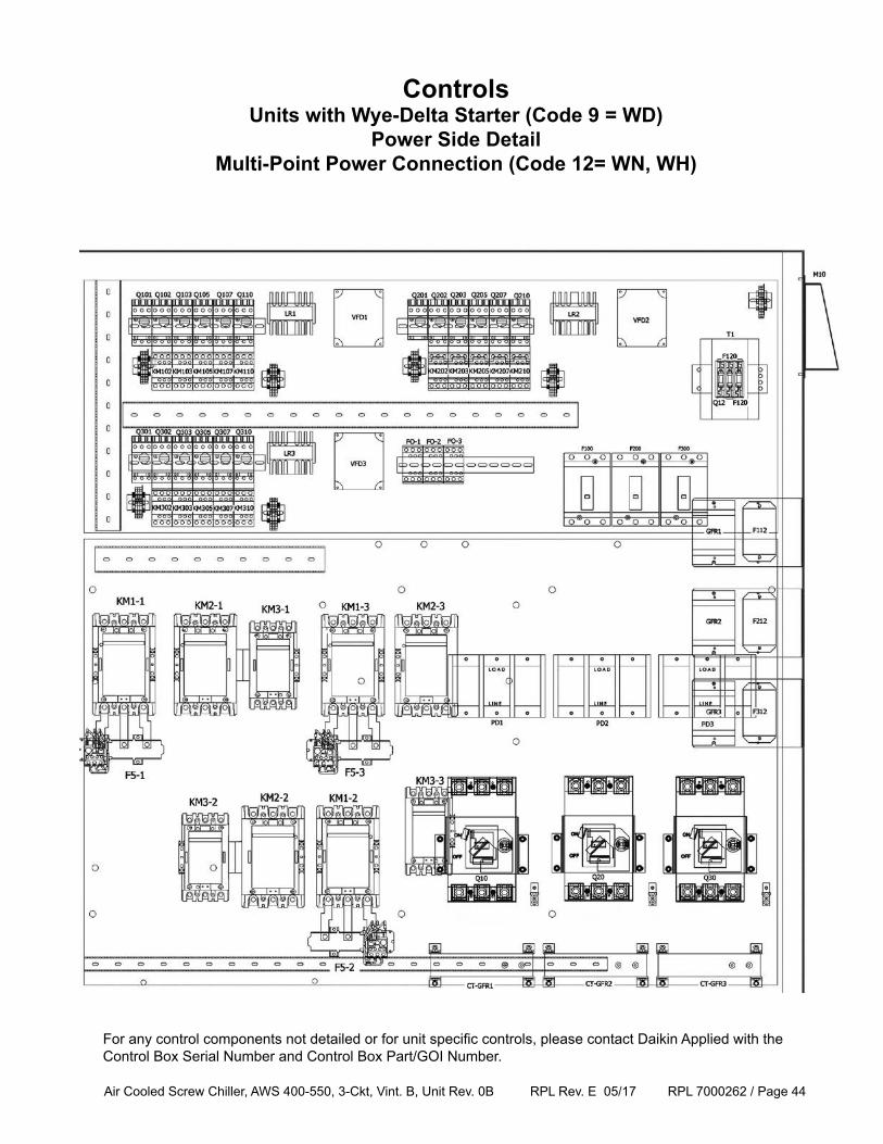
ControlsUnits with Wye-Delta Starter (Code 9 = WD)
Power Side DetailMulti-Point Power Connection (Code 12= WN, WH)
For any control components not detailed or for unit specific controls, please contact Daikin Applied with the Control Box Serial Number and Control Box Part/GOI Number.
Air Cooled Screw Chiller, AWS 400-550, 3-Ckt, Vint. B, Unit Rev. 0B RPL Rev. E 05/17 RPL 7000262 / Page 45
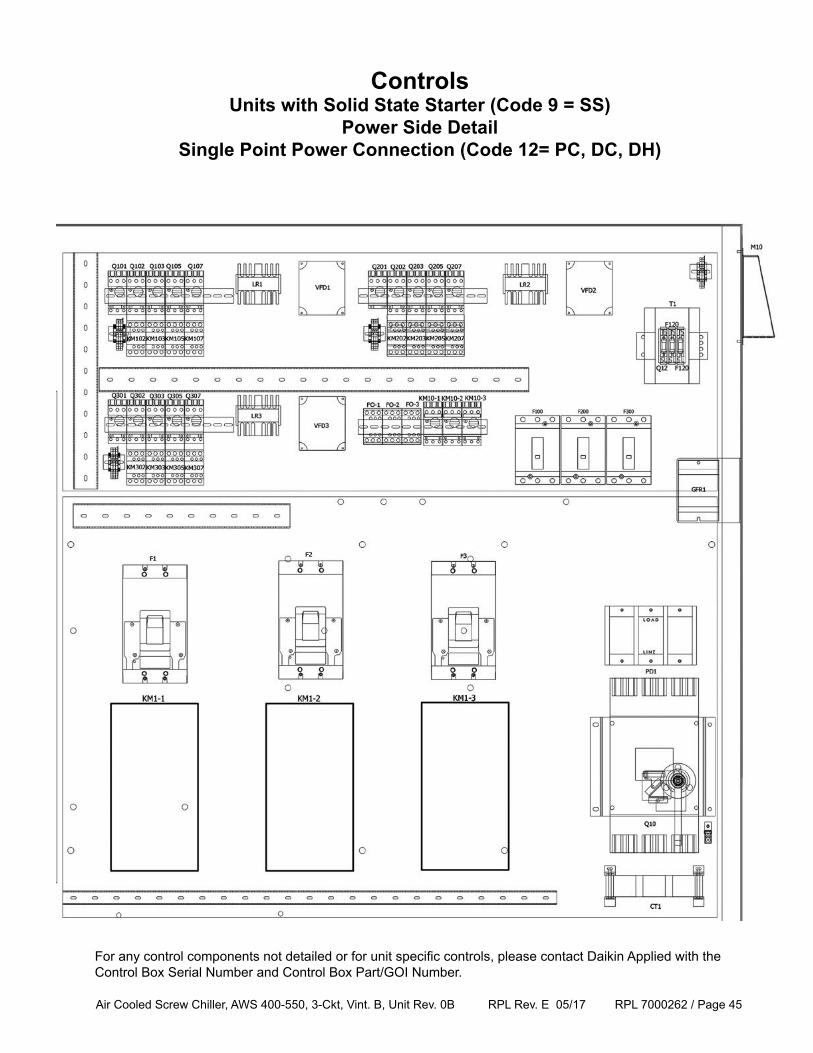
ControlsUnits with Solid State Starter (Code 9 = SS)
Power Side DetailSingle Point Power Connection (Code 12= PC, DC, DH)
For any control components not detailed or for unit specific controls, please contact Daikin Applied with the Control Box Serial Number and Control Box Part/GOI Number.
Air Cooled Screw Chiller, AWS 400-550, 3-Ckt, Vint. B, Unit Rev. 0B RPL Rev. E 05/17 RPL 7000262 / Page 46
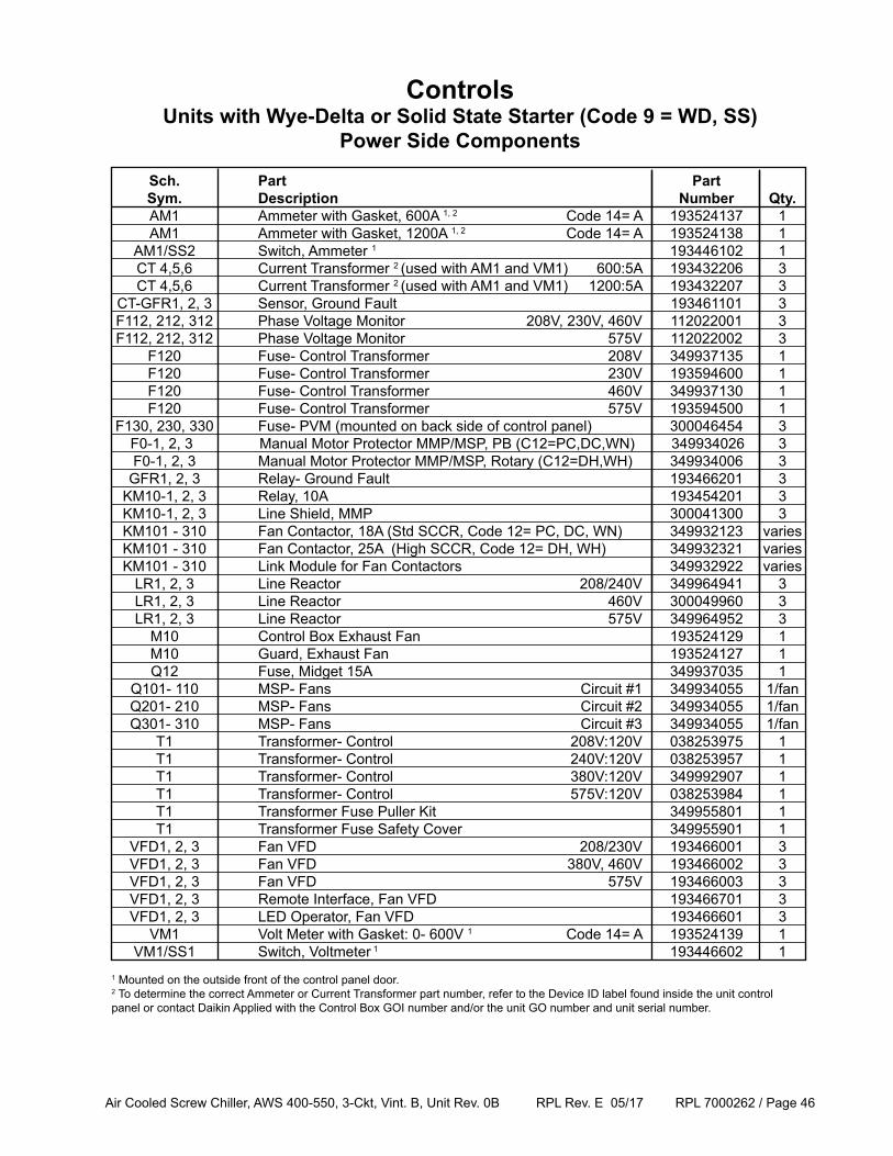
ControlsUnits with Wye-Delta or Solid State Starter (Code 9 = WD, SS)
Power Side Components
Sch. Part Part Sym. Description Number Qty. AM1 Ammeter with Gasket, 600A 1, 2 Code 14= A 193524137 1 AM1 Ammeter with Gasket, 1200A 1, 2 Code 14= A 193524138 1 AM1/SS2 Switch, Ammeter 1 193446102 1 CT 4,5,6 Current Transformer 2 (used with AM1 and VM1) 600:5A 193432206 3 CT 4,5,6 Current Transformer 2 (used with AM1 and VM1) 1200:5A 193432207 3 CT-GFR1, 2, 3 Sensor, Ground Fault 193461101 3 F112, 212, 312 Phase Voltage Monitor 208V, 230V, 460V 112022001 3 F112, 212, 312 Phase Voltage Monitor 575V 112022002 3 F120 Fuse- Control Transformer 208V 349937135 1 F120 Fuse- Control Transformer 230V 193594600 1 F120 Fuse- Control Transformer 460V 349937130 1 F120 Fuse- Control Transformer 575V 193594500 1 F130, 230, 330 Fuse- PVM (mounted on back side of control panel) 300046454 3 F0-1, 2, 3 Manual Motor Protector MMP/MSP, PB (C12=PC,DC,WN) 349934026 3 F0-1, 2, 3 Manual Motor Protector MMP/MSP, Rotary (C12=DH,WH) 349934006 3 GFR1, 2, 3 Relay- Ground Fault 193466201 3 KM10-1, 2, 3 Relay, 10A 193454201 3 KM10-1, 2, 3 Line Shield, MMP 300041300 3 KM101 - 310 Fan Contactor, 18A (Std SCCR, Code 12= PC, DC, WN) 349932123 varies KM101 - 310 Fan Contactor, 25A (High SCCR, Code 12= DH, WH) 349932321 varies KM101 - 310 Link Module for Fan Contactors 349932922 varies LR1, 2, 3 Line Reactor 208/240V 349964941 3 LR1, 2, 3 Line Reactor 460V 300049960 3 LR1, 2, 3 Line Reactor 575V 349964952 3 M10 Control Box Exhaust Fan 193524129 1 M10 Guard, Exhaust Fan 193524127 1 Q12 Fuse, Midget 15A 349937035 1 Q101- 110 MSP- Fans Circuit #1 349934055 1/fan Q201- 210 MSP- Fans Circuit #2 349934055 1/fan Q301- 310 MSP- Fans Circuit #3 349934055 1/fan T1 Transformer- Control 208V:120V 038253975 1 T1 Transformer- Control 240V:120V 038253957 1 T1 Transformer- Control 380V:120V 349992907 1 T1 Transformer- Control 575V:120V 038253984 1 T1 Transformer Fuse Puller Kit 349955801 1 T1 Transformer Fuse Safety Cover 349955901 1 VFD1, 2, 3 Fan VFD 208/230V 193466001 3 VFD1, 2, 3 Fan VFD 380V, 460V 193466002 3 VFD1, 2, 3 Fan VFD 575V 193466003 3 VFD1, 2, 3 Remote Interface, Fan VFD 193466701 3 VFD1, 2, 3 LED Operator, Fan VFD 193466601 3 VM1 Volt Meter with Gasket: 0- 600V 1 Code 14= A 193524139 1 VM1/SS1 Switch, Voltmeter 1 193446602 11 Mounted on the outside front of the control panel door.2 To determine the correct Ammeter or Current Transformer part number, refer to the Device ID label found inside the unit control panel or contact Daikin Applied with the Control Box GOI number and/or the unit GO number and unit serial number.
Air Cooled Screw Chiller, AWS 400-550, 3-Ckt, Vint. B, Unit Rev. 0B RPL Rev. E 05/17 RPL 7000262 / Page 47
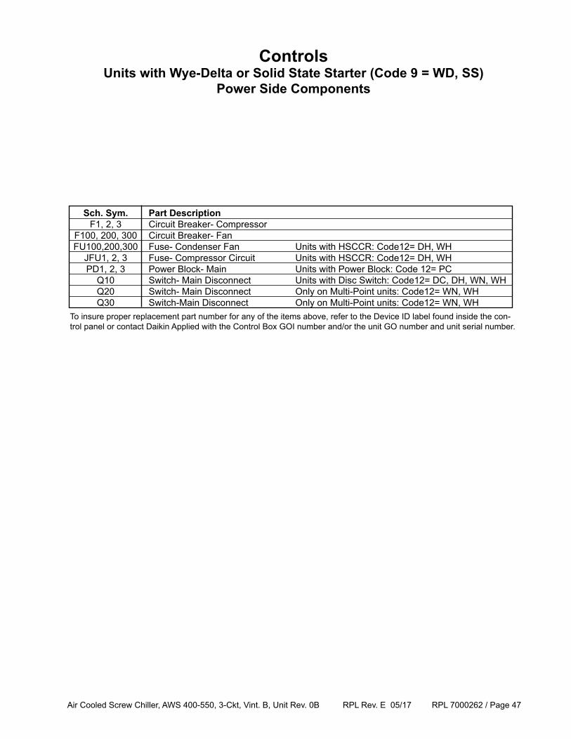
Sch. Sym. Part Description F1, 2, 3 Circuit Breaker- Compressor F100, 200, 300 Circuit Breaker- Fan FU100,200,300 Fuse- Condenser Fan Units with HSCCR: Code12= DH, WH JFU1, 2, 3 Fuse- Compressor Circuit Units with HSCCR: Code12= DH, WH PD1, 2, 3 Power Block- Main Units with Power Block: Code 12= PC Q10 Switch- Main Disconnect Units with Disc Switch: Code12= DC, DH, WN, WH Q20 Switch- Main Disconnect Only on Multi-Point units: Code12= WN, WH Q30 Switch-Main Disconnect Only on Multi-Point units: Code12= WN, WHTo insure proper replacement part number for any of the items above, refer to the Device ID label found inside the con-trol panel or contact Daikin Applied with the Control Box GOI number and/or the unit GO number and unit serial number.
ControlsUnits with Wye-Delta or Solid State Starter (Code 9 = WD, SS)
Power Side Components
Air Cooled Screw Chiller, AWS 400-550, 3-Ckt, Vint. B, Unit Rev. 0B RPL Rev. E 05/17 RPL 7000262 / Page 48
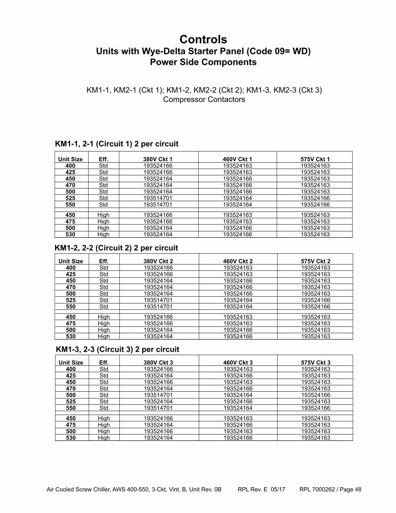
KM1-1, KM2-1 (Ckt 1); KM1-2, KM2-2 (Ckt 2); KM1-3, KM2-3 (Ckt 3)Compressor Contactors
ControlsUnits with Wye-Delta Starter Panel (Code 09= WD)
Power Side Components
Unit Size Eff. 380V Ckt 1 460V Ckt 1 575V Ckt 1 400 Std 193524166 193524163 193524163 425 Std 193524166 193524163 193524163 450 Std 193524164 193524166 193524163 470 Std 193524164 193524166 193524163 500 Std 193524164 193524166 193524163 525 Std 193514701 193524164 193524166 550 Std 193514701 193524164 193524166
450 High 193524166 193524163 193524163 475 High 193524166 193524163 193524163 500 High 193524164 193524166 193524163 530 High 193524164 193524166 193524163
Unit Size Eff. 380V Ckt 2 460V Ckt 2 575V Ckt 2 400 Std 193524166 193524163 193524163 425 Std 193524166 193524163 193524163 450 Std 193524164 193524166 193524163 470 Std 193524164 193524166 193524163 500 Std 193524164 193524166 193524163 525 Std 193514701 193524164 193524166 550 Std 193514701 193524164 193524166
450 High 193524166 193524163 193524163 475 High 193524166 193524163 193524163 500 High 193524164 193524166 193524163 530 High 193524164 193524166 193524163
Unit Size Eff. 380V Ckt 3 460V Ckt 3 575V Ckt 3 400 Std 193524166 193524163 193524163 425 Std 193524164 193524166 193524163 450 Std 193524166 193524163 193524163 470 Std 193524164 193524166 193524163 500 Std 193514701 193524164 193524166 525 Std 193524164 193524166 193524163 550 Std 193514701 193524164 193524166
450 High 193524166 193524163 193524163 475 High 193524164 193524166 193524163 500 High 193524166 193524163 193524163 530 High 193524164 193524166 193524163
KM1-1, 2-1 (Circuit 1) 2 per circuit
KM1-2, 2-2 (Circuit 2) 2 per circuit
KM1-3, 2-3 (Circuit 3) 2 per circuit
Air Cooled Screw Chiller, AWS 400-550, 3-Ckt, Vint. B, Unit Rev. 0B RPL Rev. E 05/17 RPL 7000262 / Page 49
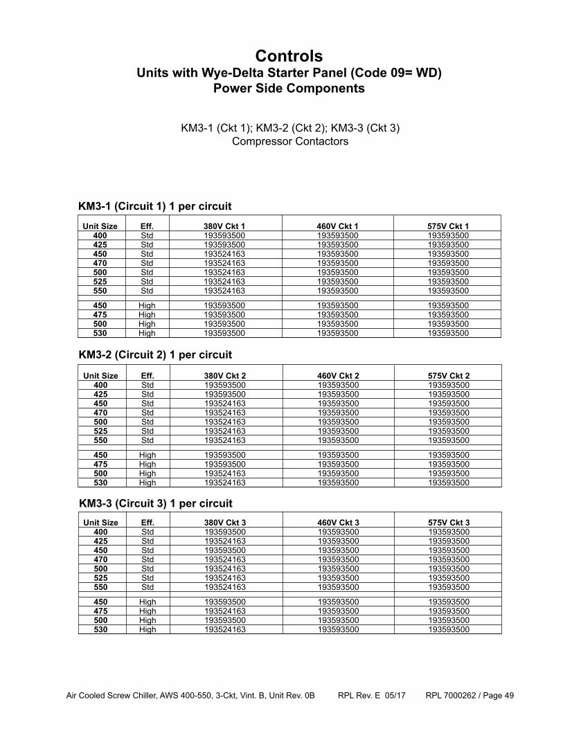
KM3-1 (Ckt 1); KM3-2 (Ckt 2); KM3-3 (Ckt 3)Compressor Contactors
ControlsUnits with Wye-Delta Starter Panel (Code 09= WD)
Power Side Components
Unit Size Eff. 380V Ckt 1 460V Ckt 1 575V Ckt 1 400 Std 193593500 193593500 193593500 425 Std 193593500 193593500 193593500 450 Std 193524163 193593500 193593500 470 Std 193524163 193593500 193593500 500 Std 193524163 193593500 193593500 525 Std 193524163 193593500 193593500 550 Std 193524163 193593500 193593500
450 High 193593500 193593500 193593500 475 High 193593500 193593500 193593500 500 High 193593500 193593500 193593500 530 High 193593500 193593500 193593500
Unit Size Eff. 380V Ckt 2 460V Ckt 2 575V Ckt 2 400 Std 193593500 193593500 193593500 425 Std 193593500 193593500 193593500 450 Std 193524163 193593500 193593500 470 Std 193524163 193593500 193593500 500 Std 193524163 193593500 193593500 525 Std 193524163 193593500 193593500 550 Std 193524163 193593500 193593500
450 High 193593500 193593500 193593500 475 High 193593500 193593500 193593500 500 High 193524163 193593500 193593500 530 High 193524163 193593500 193593500
Unit Size Eff. 380V Ckt 3 460V Ckt 3 575V Ckt 3 400 Std 193593500 193593500 193593500 425 Std 193524163 193593500 193593500 450 Std 193593500 193593500 193593500 470 Std 193524163 193593500 193593500 500 Std 193524163 193593500 193593500 525 Std 193524163 193593500 193593500 550 Std 193524163 193593500 193593500
450 High 193593500 193593500 193593500 475 High 193524163 193593500 193593500 500 High 193593500 193593500 193593500 530 High 193524163 193593500 193593500
KM3-1 (Circuit 1) 1 per circuit
KM3-2 (Circuit 2) 1 per circuit
KM3-3 (Circuit 3) 1 per circuit
Air Cooled Screw Chiller, AWS 400-550, 3-Ckt, Vint. B, Unit Rev. 0B RPL Rev. E 05/17 RPL 7000262 / Page 50
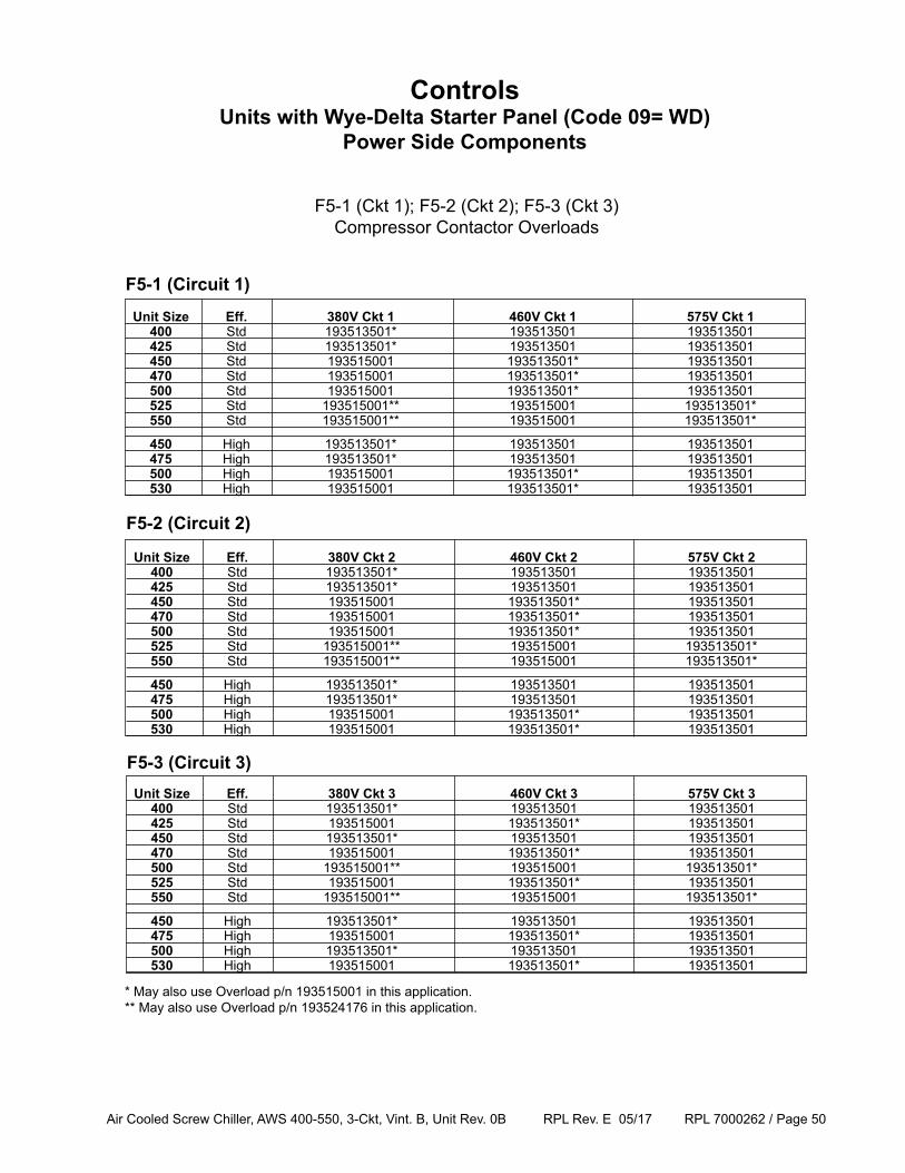
F5-1 (Ckt 1); F5-2 (Ckt 2); F5-3 (Ckt 3)Compressor Contactor Overloads
ControlsUnits with Wye-Delta Starter Panel (Code 09= WD)
Power Side Components
Unit Size Eff. 380V Ckt 1 460V Ckt 1 575V Ckt 1 400 Std 193513501* 193513501 193513501 425 Std 193513501* 193513501 193513501 450 Std 193515001 193513501* 193513501 470 Std 193515001 193513501* 193513501 500 Std 193515001 193513501* 193513501 525 Std 193515001** 193515001 193513501* 550 Std 193515001** 193515001 193513501*
450 High 193513501* 193513501 193513501 475 High 193513501* 193513501 193513501 500 High 193515001 193513501* 193513501 530 High 193515001 193513501* 193513501
Unit Size Eff. 380V Ckt 2 460V Ckt 2 575V Ckt 2 400 Std 193513501* 193513501 193513501 425 Std 193513501* 193513501 193513501 450 Std 193515001 193513501* 193513501 470 Std 193515001 193513501* 193513501 500 Std 193515001 193513501* 193513501 525 Std 193515001** 193515001 193513501* 550 Std 193515001** 193515001 193513501*
450 High 193513501* 193513501 193513501 475 High 193513501* 193513501 193513501 500 High 193515001 193513501* 193513501 530 High 193515001 193513501* 193513501
Unit Size Eff. 380V Ckt 3 460V Ckt 3 575V Ckt 3 400 Std 193513501* 193513501 193513501 425 Std 193515001 193513501* 193513501 450 Std 193513501* 193513501 193513501 470 Std 193515001 193513501* 193513501 500 Std 193515001** 193515001 193513501* 525 Std 193515001 193513501* 193513501 550 Std 193515001** 193515001 193513501*
450 High 193513501* 193513501 193513501 475 High 193515001 193513501* 193513501 500 High 193513501* 193513501 193513501 530 High 193515001 193513501* 193513501
F5-1 (Circuit 1)
F5-2 (Circuit 2)
F5-3 (Circuit 3)
* May also use Overload p/n 193515001 in this application.** May also use Overload p/n 193524176 in this application.
Air Cooled Screw Chiller, AWS 400-550, 3-Ckt, Vint. B, Unit Rev. 0B RPL Rev. E 05/17 RPL 7000262 / Page 51
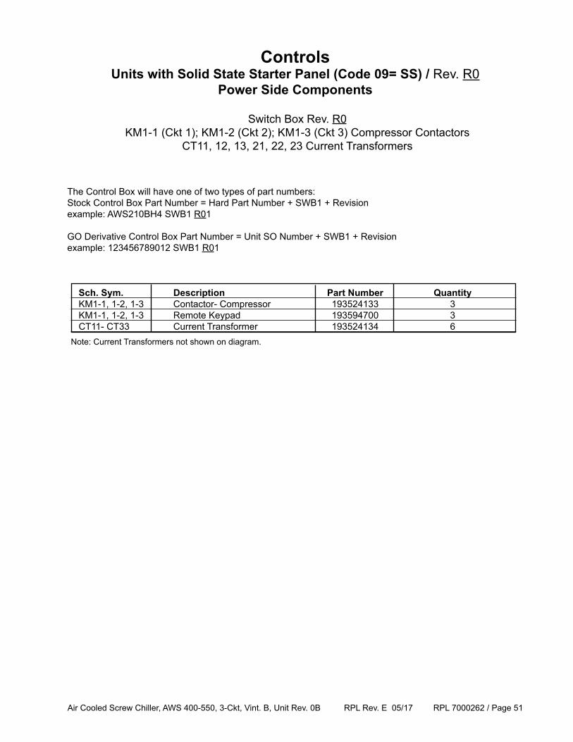
Switch Box Rev. R0 KM1-1 (Ckt 1); KM1-2 (Ckt 2); KM1-3 (Ckt 3) Compressor Contactors
CT11, 12, 13, 21, 22, 23 Current Transformers
The Control Box will have one of two types of part numbers:Stock Control Box Part Number = Hard Part Number + SWB1 + Revisionexample: AWS210BH4 SWB1 R01
GO Derivative Control Box Part Number = Unit SO Number + SWB1 + Revisionexample: 123456789012 SWB1 R01
ControlsUnits with Solid State Starter Panel (Code 09= SS) / Rev. R0
Power Side Components
Sch. Sym. Description Part Number Quantity KM1-1, 1-2, 1-3 Contactor- Compressor 193524133 3 KM1-1, 1-2, 1-3 Remote Keypad 193594700 3 CT11- CT33 Current Transformer 193524134 6Note: Current Transformers not shown on diagram.
Air Cooled Screw Chiller, AWS 400-550, 3-Ckt, Vint. B, Unit Rev. 0B RPL Rev. E 05/17 RPL 7000262 / Page 52
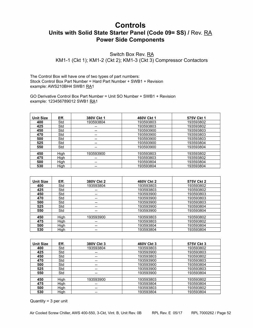
Switch Box Rev. RA KM1-1 (Ckt 1); KM1-2 (Ckt 2); KM1-3 (Ckt 3) Compressor Contactors
The Control Box will have one of two types of part numbers:Stock Control Box Part Number = Hard Part Number + SWB1 + Revisionexample: AWS210BH4 SWB1 RA1
GO Derivative Control Box Part Number = Unit SO Number + SWB1 + Revisionexample: 123456789012 SWB1 RA1
ControlsUnits with Solid State Starter Panel (Code 09= SS) / Rev. RA
Power Side Components
Unit Size Eff. 380V Ckt 1 460V Ckt 1 575V Ckt 1 400 Std 193593804 193593803 193593802 425 Std -- 193593803 193593802 450 Std -- 193593900 193593803 470 Std -- 193593900 193593803 500 Std -- 193593900 193593803 525 Std -- 193593900 193593804 550 Std -- 193593900 193593804
450 High 193593900 193593803 193593802 475 High -- 193593803 193593802 500 High -- 193593804 193593804 530 High -- 193593804 193593804
Unit Size Eff. 380V Ckt 2 460V Ckt 2 575V Ckt 2 400 Std 193593804 193593803 193593802 425 Std -- 193593803 193593802 450 Std -- 193593900 193593803 470 Std -- 193593900 193593803 500 Std -- 193593900 193593803 525 Std -- 193593900 193593804 550 Std -- 193593900 193593804
450 High 193593900 193593803 193593802 475 High -- 193593803 193593802 500 High -- 193593804 193593804 530 High -- 193593804 193593804
Unit Size Eff. 380V Ckt 3 460V Ckt 3 575V Ckt 3 400 Std 193593804 193593803 193593802 425 Std -- 193593900 193593803 450 Std -- 193593803 193593802 470 Std -- 193593900 193593803 500 Std -- 193593900 193593804 525 Std -- 193593900 193593803 550 Std -- 193593900 193593804
450 High 193593900 193593803 193593802 475 High -- 193593804 193593804 500 High -- 193593803 193593802 530 High -- 193593804 193593804
Quantity = 3 per unit
Air Cooled Screw Chiller, AWS 400-550, 3-Ckt, Vint. B, Unit Rev. 0B RPL Rev. E 05/17 RPL 7000262 / Page 53
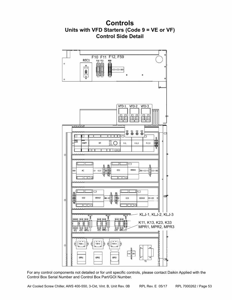
ControlsUnits with VFD Starters (Code 9 = VE or VF)
Control Side Detail
F10 F11 F12, F59
KLJ-1, KLJ-2, KLJ-3
K11, K13, K23, K33MPR1, MPR2, MPR3
For any control components not detailed or for unit specific controls, please contact Daikin Applied with the Control Box Serial Number and Control Box Part/GOI Number.
Air Cooled Screw Chiller, AWS 400-550, 3-Ckt, Vint. B, Unit Rev. 0B RPL Rev. E 05/17 RPL 7000262 / Page 54
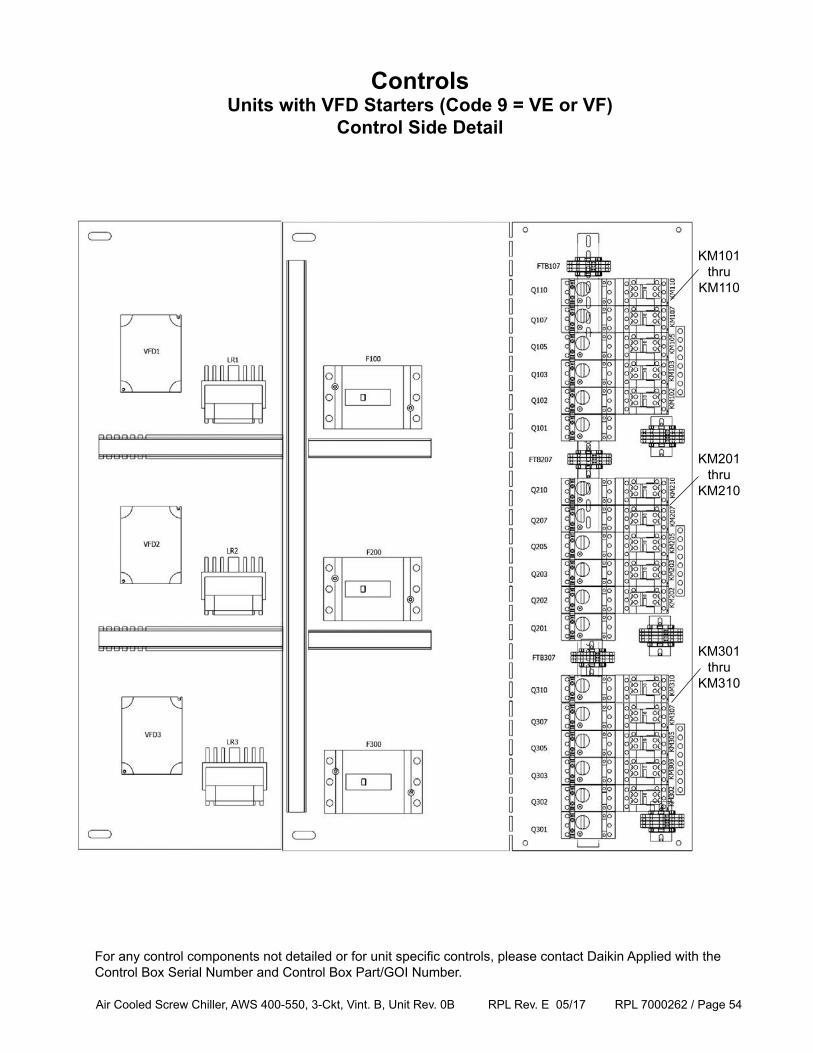
ControlsUnits with VFD Starters (Code 9 = VE or VF)
Control Side Detail
KM101thru
KM110
KM201thru
KM210
KM301thru
KM310
For any control components not detailed or for unit specific controls, please contact Daikin Applied with the Control Box Serial Number and Control Box Part/GOI Number.
Air Cooled Screw Chiller, AWS 400-550, 3-Ckt, Vint. B, Unit Rev. 0B RPL Rev. E 05/17 RPL 7000262 / Page 55
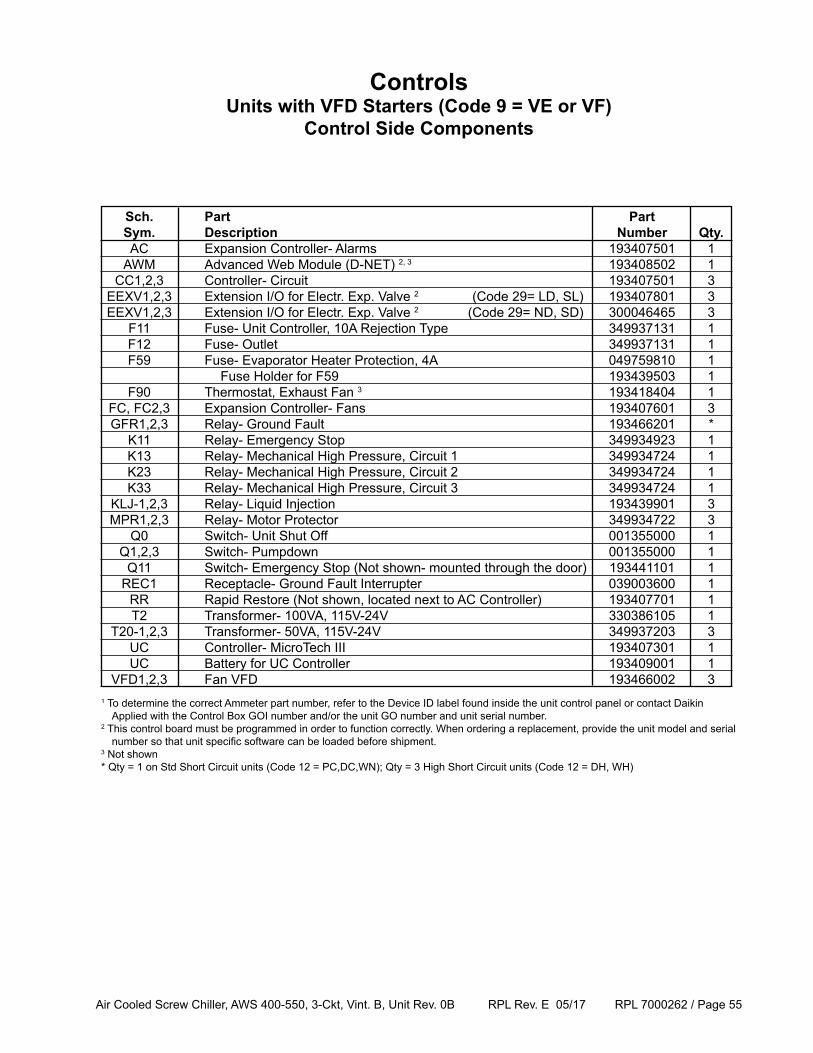
Sch. Part Part Sym. Description Number Qty. AC Expansion Controller- Alarms 193407501 1 AWM Advanced Web Module (D-NET) 2, 3 193408502 1 CC1,2,3 Controller- Circuit 193407501 3 EEXV1,2,3 Extension I/O for Electr. Exp. Valve 2 (Code 29= LD, SL) 193407801 3 EEXV1,2,3 Extension I/O for Electr. Exp. Valve 2 (Code 29= ND, SD) 300046465 3 F11 Fuse- Unit Controller, 10A Rejection Type 349937131 1 F12 Fuse- Outlet 349937131 1 F59 Fuse- Evaporator Heater Protection, 4A 049759810 1 Fuse Holder for F59 193439503 1 F90 Thermostat, Exhaust Fan 3 193418404 1 FC, FC2,3 Expansion Controller- Fans 193407601 3 GFR1,2,3 Relay- Ground Fault 193466201 * K11 Relay- Emergency Stop 349934923 1 K13 Relay- Mechanical High Pressure, Circuit 1 349934724 1 K23 Relay- Mechanical High Pressure, Circuit 2 349934724 1 K33 Relay- Mechanical High Pressure, Circuit 3 349934724 1 KLJ-1,2,3 Relay- Liquid Injection 193439901 3 MPR1,2,3 Relay- Motor Protector 349934722 3 Q0 Switch- Unit Shut Off 001355000 1 Q1,2,3 Switch- Pumpdown 001355000 1 Q11 Switch- Emergency Stop (Not shown- mounted through the door) 193441101 1 REC1 Receptacle- Ground Fault Interrupter 039003600 1 RR Rapid Restore (Not shown, located next to AC Controller) 193407701 1 T2 Transformer- 100VA, 115V-24V 330386105 1 T20-1,2,3 Transformer- 50VA, 115V-24V 349937203 3 UC Controller- MicroTech III 193407301 1 UC Battery for UC Controller 193409001 1 VFD1,2,3 Fan VFD 193466002 3
ControlsUnits with VFD Starters (Code 9 = VE or VF)
Control Side Components
1 To determine the correct Ammeter part number, refer to the Device ID label found inside the unit control panel or contact Daikin Applied with the Control Box GOI number and/or the unit GO number and unit serial number.2 This control board must be programmed in order to function correctly. When ordering a replacement, provide the unit model and serial number so that unit specific software can be loaded before shipment.3 Not shown* Qty = 1 on Std Short Circuit units (Code 12 = PC,DC,WN); Qty = 3 High Short Circuit units (Code 12 = DH, WH)
Air Cooled Screw Chiller, AWS 400-550, 3-Ckt, Vint. B, Unit Rev. 0B RPL Rev. E 05/17 RPL 7000262 / Page 56
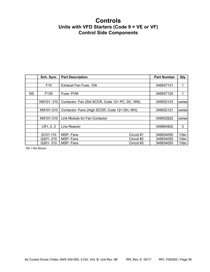
Sch. Sym. Part Description Part Number Qty
F10 Exhaust Fan Fuse, 10A 349937131 1
NS F130 Fuse- PVM 349937120 1
KM101- 310 Contactor- Fan (Std SCCR, Code 12= PC, DC, WN) 349932123 varies
KM101-310 Contactor- Fans (High SCCR, Code 12= DH, WH) 349932121 varies
KM101-310 Link Module for Fan Contactor 349932922 varies
LR1, 2, 3 Line Reactor 349964902 3
Q101-110 MSP- Fans Circuit #1 349934055 1/fan Q201- 210 MSP- Fans Circuit #2 349934055 1/fan Q301- 310 MSP- Fans Circuit #3 349934055 1/fanNS = Not Shown
ControlsUnits with VFD Starters (Code 9 = VE or VF)
Control Side Components
Air Cooled Screw Chiller, AWS 400-550, 3-Ckt, Vint. B, Unit Rev. 0B RPL Rev. E 05/17 RPL 7000262 / Page 57
ControlsUnits with VFD Starters (Code 9 = VE or VF)
Control Side Components
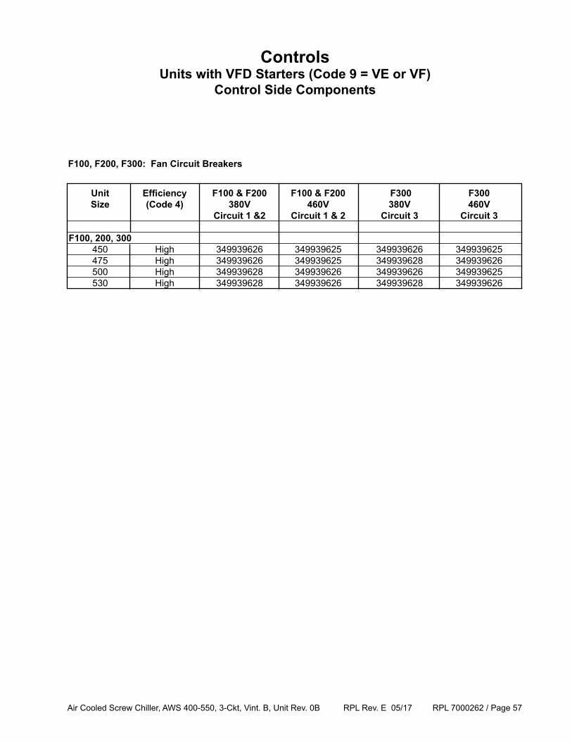
Unit Efficiency F100 & F200 F100 & F200 F300 F300 Size (Code 4) 380V 460V 380V 460V Circuit 1 &2 Circuit 1 & 2 Circuit 3 Circuit 3 F100, 200, 300 450 High 349939626 349939625 349939626 349939625 475 High 349939626 349939625 349939628 349939626 500 High 349939628 349939626 349939626 349939625 530 High 349939628 349939626 349939628 349939626
F100, F200, F300: Fan Circuit Breakers
Air Cooled Screw Chiller, AWS 400-550, 3-Ckt, Vint. B, Unit Rev. 0B RPL Rev. E 05/17 RPL 7000262 / Page 58
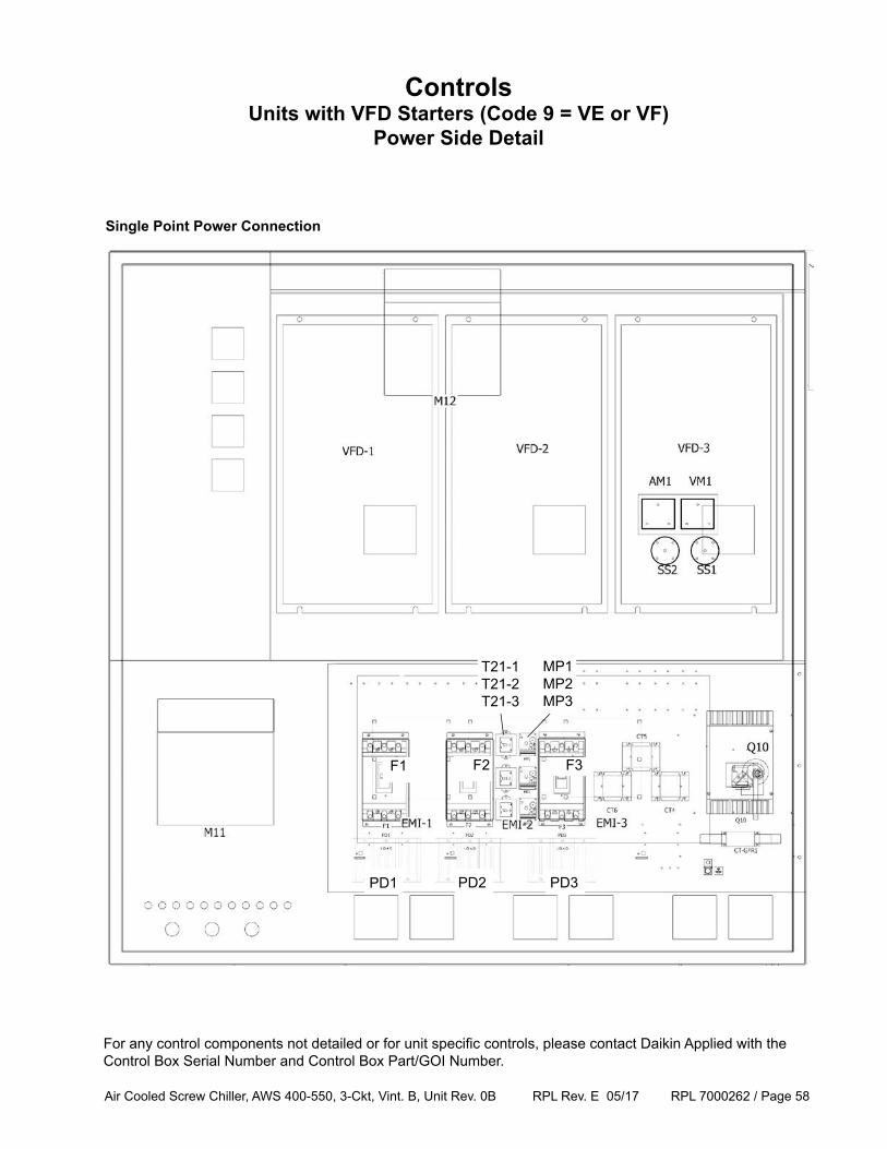
ControlsUnits with VFD Starters (Code 9 = VE or VF)
Power Side Detail
Single Point Power Connection
F1 F2 F3
For any control components not detailed or for unit specific controls, please contact Daikin Applied with the Control Box Serial Number and Control Box Part/GOI Number.
PD1 PD2 PD3
MP1MP2MP3
T21-1T21-2T21-3
Air Cooled Screw Chiller, AWS 400-550, 3-Ckt, Vint. B, Unit Rev. 0B RPL Rev. E 05/17 RPL 7000262 / Page 59
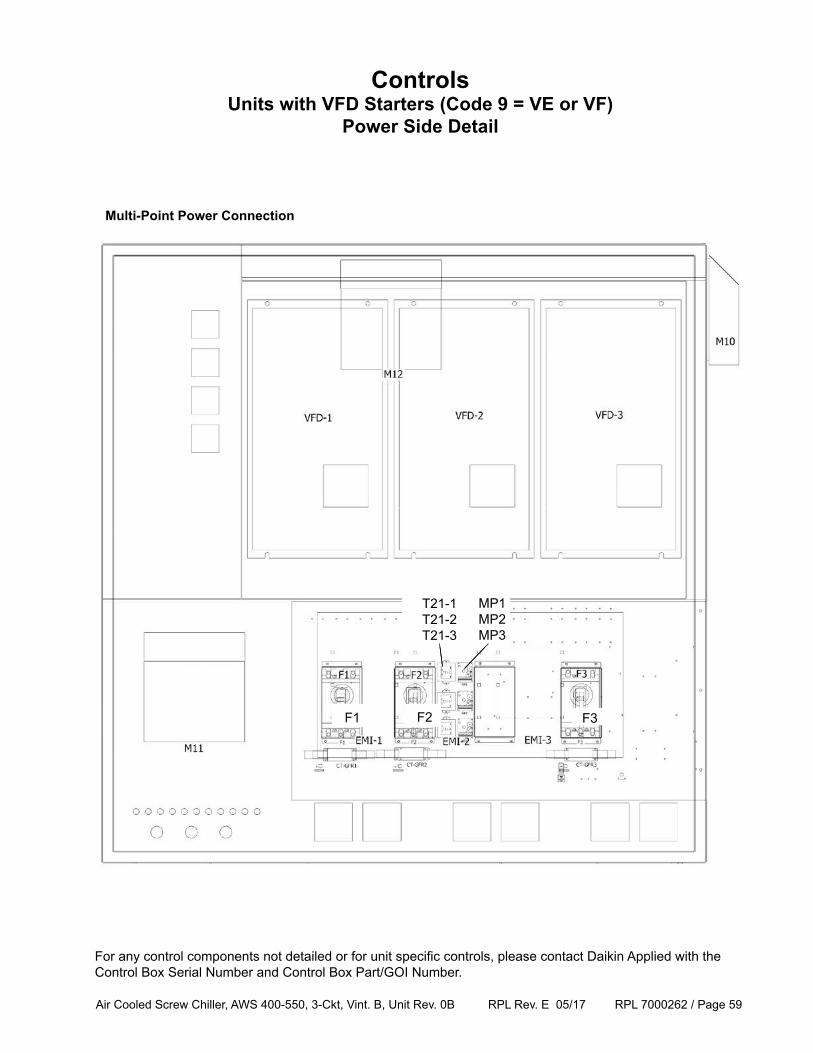
ControlsUnits with VFD Starters (Code 9 = VE or VF)
Power Side Detail
Multi-Point Power Connection
F1 F2 F3
T21-1T21-2T21-3
MP1MP2MP3
For any control components not detailed or for unit specific controls, please contact Daikin Applied with the Control Box Serial Number and Control Box Part/GOI Number.
F1 F2 F3
T21-1T21-2T21-3
MP1MP2MP3
Air Cooled Screw Chiller, AWS 400-550, 3-Ckt, Vint. B, Unit Rev. 0B RPL Rev. E 05/17 RPL 7000262 / Page 60
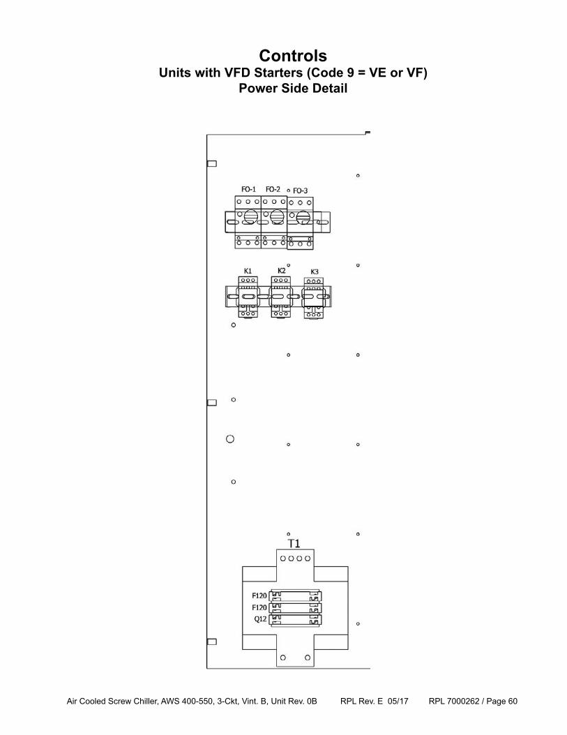
ControlsUnits with VFD Starters (Code 9 = VE or VF)
Power Side Detail
Air Cooled Screw Chiller, AWS 400-550, 3-Ckt, Vint. B, Unit Rev. 0B RPL Rev. E 05/17 RPL 7000262 / Page 61
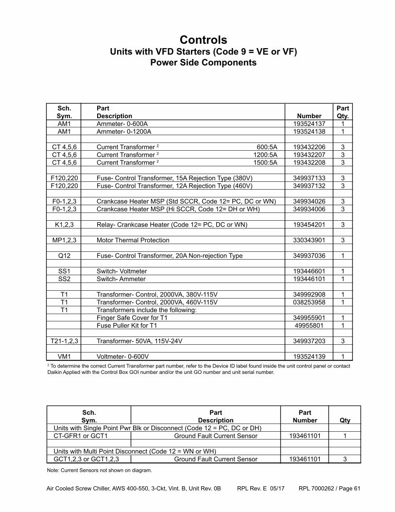
Sch. Part Part Sym. Description Number Qty. AM1 Ammeter- 0-600A 193524137 1 AM1 Ammeter- 0-1200A 193524138 1
CT 4,5,6 Current Transformer 2 600:5A 193432206 3 CT 4,5,6 Current Transformer 2 1200:5A 193432207 3 CT 4,5,6 Current Transformer 2 1500:5A 193432208 3
F120,220 Fuse- Control Transformer, 15A Rejection Type (380V) 349937133 3 F120,220 Fuse- Control Transformer, 12A Rejection Type (460V) 349937132 3
F0-1,2,3 Crankcase Heater MSP (Std SCCR, Code 12= PC, DC or WN) 349934026 3 F0-1,2,3 Crankcase Heater MSP (Hi SCCR, Code 12= DH or WH) 349934006 3 K1,2,3 Relay- Crankcase Heater (Code 12= PC, DC or WN) 193454201 3
MP1,2,3 Motor Thermal Protection 330343901 3
Q12 Fuse- Control Transformer, 20A Non-rejection Type 349937036 1
SS1 Switch- Voltmeter 193446601 1 SS2 Switch- Ammeter 193446101 1
T1 Transformer- Control, 2000VA, 380V-115V 349992908 1 T1 Transformer- Control, 2000VA, 460V-115V 038253958 1 T1 Transformers include the following: Finger Safe Cover for T1 349955901 1 Fuse Puller Kit for T1 49955801 1
T21-1,2,3 Transformer- 50VA, 115V-24V 349937203 3
VM1 Voltmeter- 0-600V 193524139 1
ControlsUnits with VFD Starters (Code 9 = VE or VF)
Power Side Components
Sch. Part Part Sym. Description Number Qty Units with Single Point Pwr Blk or Disconnect (Code 12 = PC, DC or DH) CT-GFR1 or GCT1 Ground Fault Current Sensor 193461101 1
Units with Multi Point Disconnect (Code 12 = WN or WH) GCT1,2,3 or GCT1,2,3 Ground Fault Current Sensor 193461101 3Note: Current Sensors not shown on diagram.
2 To determine the correct Current Transformer part number, refer to the Device ID label found inside the unit control panel or contact Daikin Applied with the Control Box GOI number and/or the unit GO number and unit serial number.
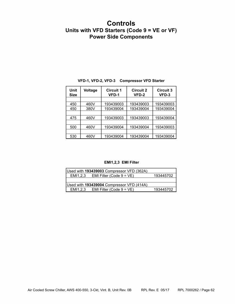
Air Cooled Screw Chiller, AWS 400-550, 3-Ckt, Vint. B, Unit Rev. 0B RPL Rev. E 05/17 RPL 7000262 / Page 62
Unit Voltage Circuit 1 Circuit 2 Circuit 3 Size VFD-1 VFD-2 VFD-3 450 460V 193439003 193439003 193439003 450 380V 193439004 193439004 193439004 475 460V 193439003 193439003 193439004 500 460V 193439004 193439004 193439003 530 460V 193439004 193439004 193439004
Used with 193439003 Compressor VFD (362A) EMI1,2,3 EMI Filter (Code 9 = VE) 193445702
Used with 193439004 Compressor VFD (414A) EMI1,2,3 EMI Filter (Code 9 = VE) 193445702
VFD-1, VFD-2, VFD-3 Compressor VFD Starter
ControlsUnits with VFD Starters (Code 9 = VE or VF)
Power Side Components
EMI1,2,3 EMI Filter
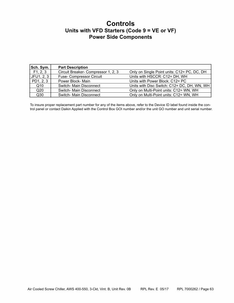
Air Cooled Screw Chiller, AWS 400-550, 3-Ckt, Vint. B, Unit Rev. 0B RPL Rev. E 05/17 RPL 7000262 / Page 63
ControlsUnits with VFD Starters (Code 9 = VE or VF)
Power Side Components
Sch. Sym. Part Description F1, 2, 3 Circuit Breaker- Compressor 1, 2, 3 Only on Single Point units: C12= PC, DC, DH JFU1, 2, 3 Fuse- Compressor Circuit Units with HSCCR: C12= DH, WH PD1, 2, 3 Power Block- Main Units with Power Block: C12= PC Q10 Switch- Main Disconnect Units with Disc Switch: C12= DC, DH, WN, WH Q20 Switch- Main Disconnect Only on Multi-Point units: C12= WN, WH Q30 Switch- Main Disconnect Only on Multi-Point units: C12= WN, WH
To insure proper replacement part number for any of the items above, refer to the Device ID label found inside the con-trol panel or contact Daikin Applied with the Control Box GOI number and/or the unit GO number and unit serial number.
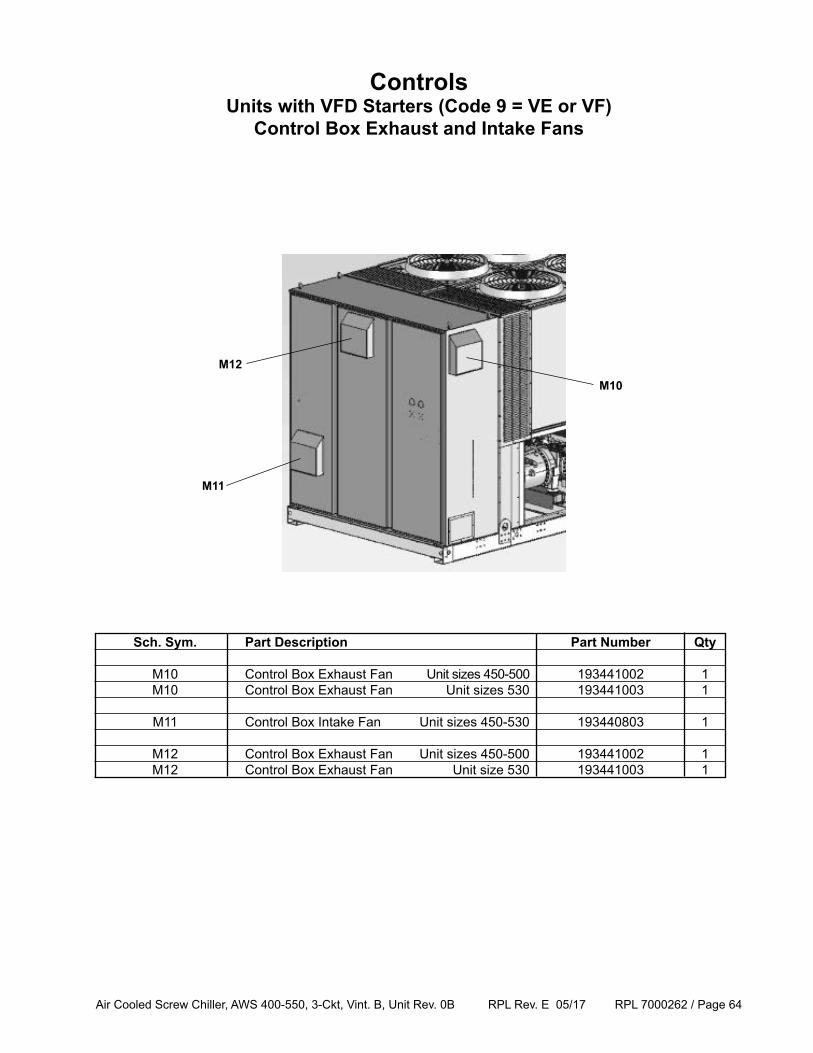
Air Cooled Screw Chiller, AWS 400-550, 3-Ckt, Vint. B, Unit Rev. 0B RPL Rev. E 05/17 RPL 7000262 / Page 64
Sch. Sym. Part Description Part Number Qty
M10 Control Box Exhaust Fan Unit sizes 450-500 193441002 1 M10 Control Box Exhaust Fan Unit sizes 530 193441003 1
M11 Control Box Intake Fan Unit sizes 450-530 193440803 1
M12 Control Box Exhaust Fan Unit sizes 450-500 193441002 1 M12 Control Box Exhaust Fan Unit size 530 193441003 1
ControlsUnits with VFD Starters (Code 9 = VE or VF)
Control Box Exhaust and Intake Fans
M12
M10
M11
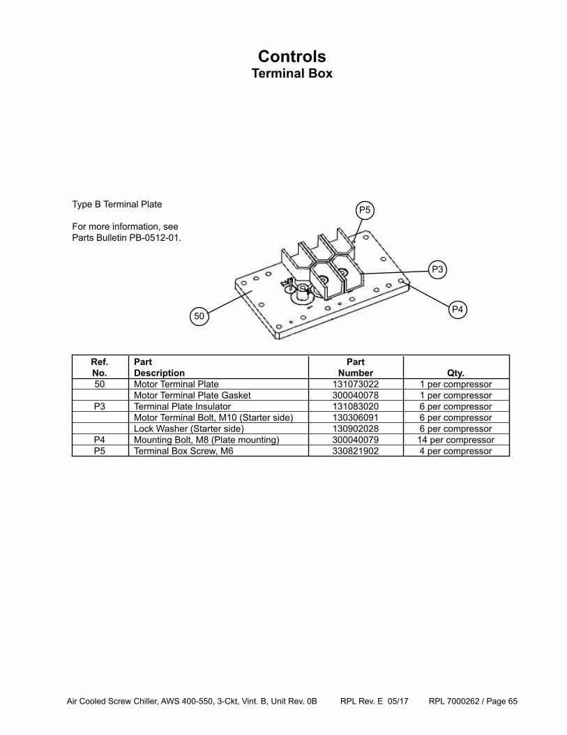
Air Cooled Screw Chiller, AWS 400-550, 3-Ckt, Vint. B, Unit Rev. 0B RPL Rev. E 05/17 RPL 7000262 / Page 65
ControlsTerminal Box
Ref. Part Part No. Description Number Qty. 50 Motor Terminal Plate 131073022 1 per compressor Motor Terminal Plate Gasket 300040078 1 per compressor P3 Terminal Plate Insulator 131083020 6 per compressor Motor Terminal Bolt, M10 (Starter side) 130306091 6 per compressor Lock Washer (Starter side) 130902028 6 per compressor P4 Mounting Bolt, M8 (Plate mounting) 300040079 14 per compressor P5 Terminal Box Screw, M6 330821902 4 per compressor
Type B Terminal Plate For more information, see Parts Bulletin PB-0512-01.
P3
P5
P450
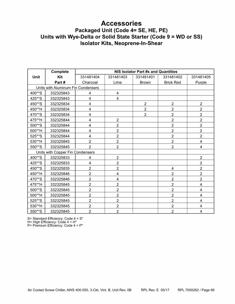
Air Cooled Screw Chiller, AWS 400-550, 3-Ckt, Vint. B, Unit Rev. 0B RPL Rev. E 05/17 RPL 7000262 / Page 66
AccessoriesPackaged Unit (Code 4= SE, HE, PE)
Units with Wye-Delta or Solid State Starter (Code 9 = WD or SS) Isolator Kits, Neoprene-In-Shear
Complete NIS Isolator Part #s and Quantities Unit Kit 331481404 331481403 331481401 331481402 331481405 Part # Charcoal Lime Brown Brick Red Purple Units with Aluminum Fin Condensers 400**S 332325843 4 4 425**S 332325843 4 4 450**S 332325834 4 2 2 2 450**H 332325834 4 2 2 2 470**S 332325834 4 2 2 2 475**H 332325844 4 2 2 2 500**S 332325844 4 2 2 2 500**H 332325844 4 2 2 2 525**S 332325844 4 2 2 2 530**H 332325845 2 2 2 4 550**S 332325845 2 2 2 4 Units with Copper Fin Condensers 400**S 332325833 4 2 2 425**S 332325833 4 2 2 450**S 332325835 2 2 4 2 450**H 332325846 2 4 2 2 470**S 332325846 2 4 2 2 475**H 332325845 2 2 2 4 500**S 332325845 2 2 2 4 500**H 332325845 2 2 2 4 525**S 332325845 2 2 2 4 530**H 332325845 2 2 2 4 550**S 332325845 2 2 2 4
S= Standard Efficiency: Code 4 = S*H= High Efficiency: Code 4 = H*P= Premium Efficiency: Code 4 = P*
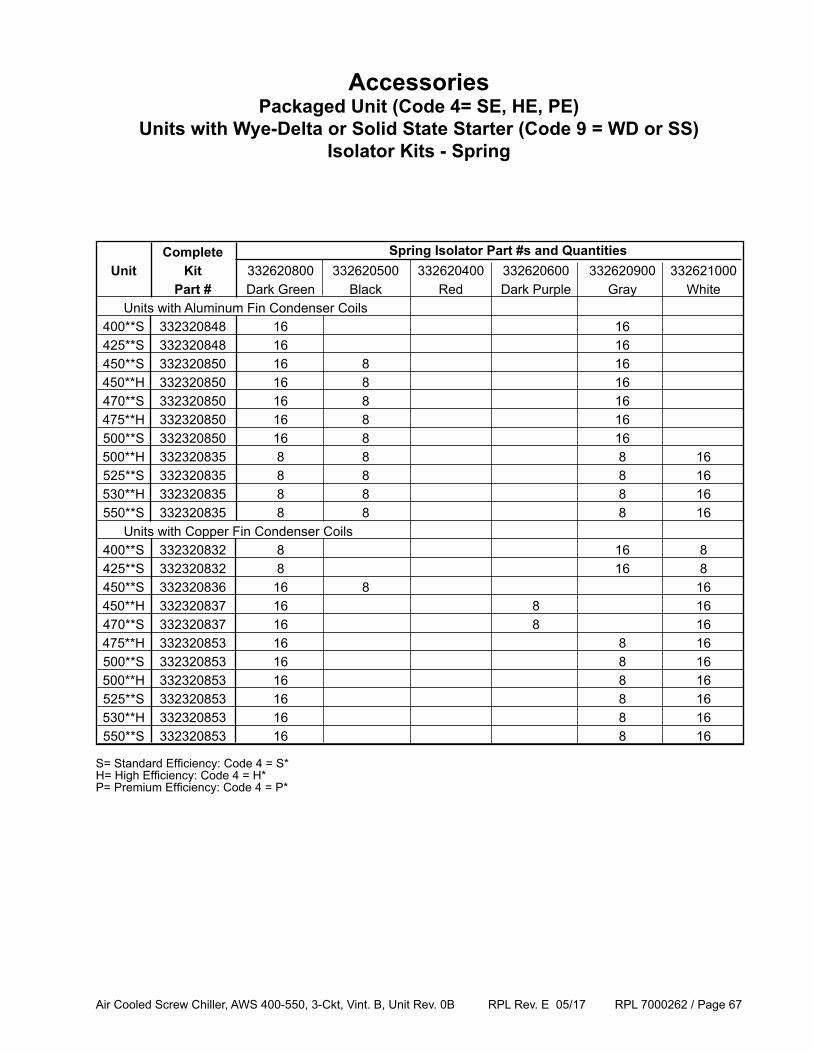
Air Cooled Screw Chiller, AWS 400-550, 3-Ckt, Vint. B, Unit Rev. 0B RPL Rev. E 05/17 RPL 7000262 / Page 67
Complete Unit Kit 332620800 332620500 332620400 332620600 332620900 332621000 Part # Dark Green Black Red Dark Purple Gray White Units with Aluminum Fin Condenser Coils 400**S 332320848 16 16 425**S 332320848 16 16 450**S 332320850 16 8 16 450**H 332320850 16 8 16 470**S 332320850 16 8 16 475**H 332320850 16 8 16 500**S 332320850 16 8 16 500**H 332320835 8 8 8 16 525**S 332320835 8 8 8 16 530**H 332320835 8 8 8 16 550**S 332320835 8 8 8 16 Units with Copper Fin Condenser Coils 400**S 332320832 8 16 8 425**S 332320832 8 16 8 450**S 332320836 16 8 16 450**H 332320837 16 8 16 470**S 332320837 16 8 16 475**H 332320853 16 8 16 500**S 332320853 16 8 16 500**H 332320853 16 8 16 525**S 332320853 16 8 16 530**H 332320853 16 8 16 550**S 332320853 16 8 16
AccessoriesPackaged Unit (Code 4= SE, HE, PE)
Units with Wye-Delta or Solid State Starter (Code 9 = WD or SS) Isolator Kits - Spring
Spring Isolator Part #s and Quantities
S= Standard Efficiency: Code 4 = S*H= High Efficiency: Code 4 = H*P= Premium Efficiency: Code 4 = P*
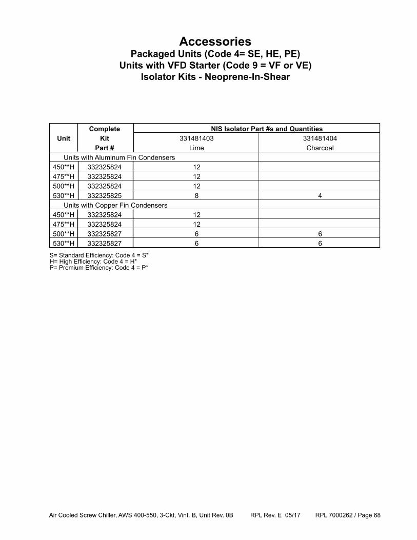
Air Cooled Screw Chiller, AWS 400-550, 3-Ckt, Vint. B, Unit Rev. 0B RPL Rev. E 05/17 RPL 7000262 / Page 68
AccessoriesPackaged Units (Code 4= SE, HE, PE)
Units with VFD Starter (Code 9 = VF or VE) Isolator Kits - Neoprene-In-Shear
Complete NIS Isolator Part #s and Quantities Unit Kit 331481403 331481404 Part # Lime Charcoal Units with Aluminum Fin Condensers 450**H 332325824 12 475**H 332325824 12 500**H 332325824 12 530**H 332325825 8 4 Units with Copper Fin Condensers 450**H 332325824 12 475**H 332325824 12 500**H 332325827 6 6 530**H 332325827 6 6
S= Standard Efficiency: Code 4 = S*H= High Efficiency: Code 4 = H*P= Premium Efficiency: Code 4 = P*
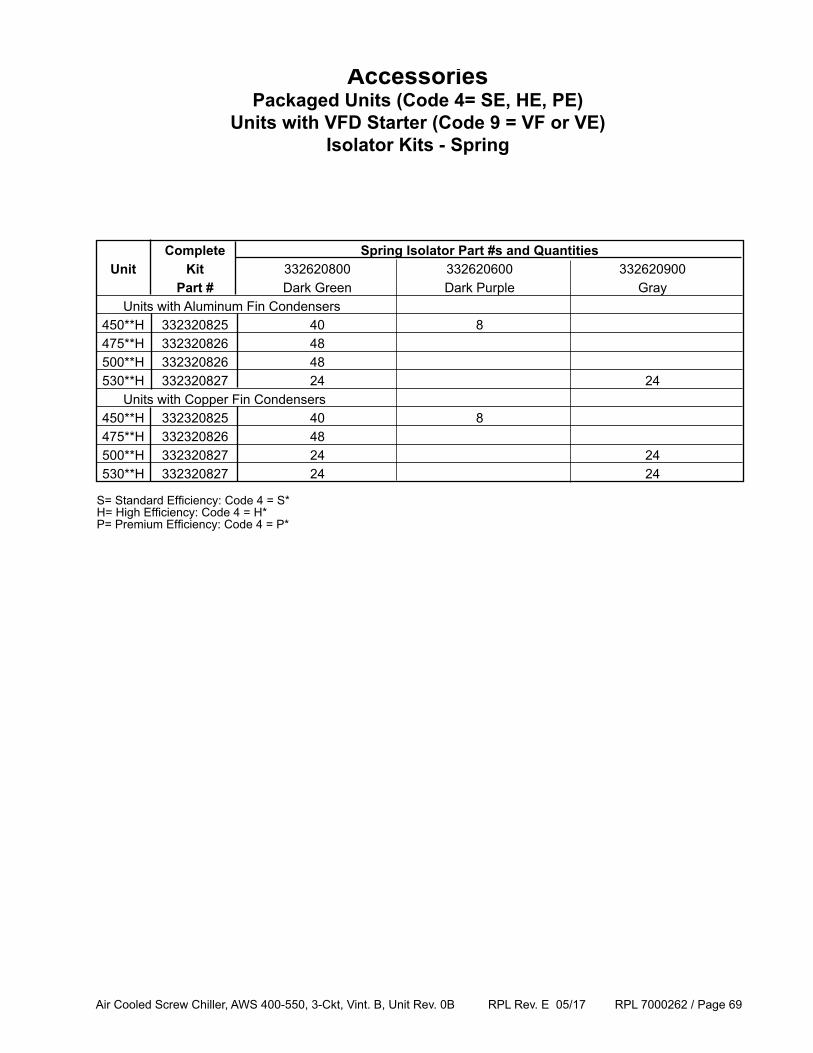
Air Cooled Screw Chiller, AWS 400-550, 3-Ckt, Vint. B, Unit Rev. 0B RPL Rev. E 05/17 RPL 7000262 / Page 69
Complete Spring Isolator Part #s and Quantities Unit Kit 332620800 332620600 332620900 Part # Dark Green Dark Purple Gray Units with Aluminum Fin Condensers 450**H 332320825 40 8 475**H 332320826 48 500**H 332320826 48 530**H 332320827 24 24 Units with Copper Fin Condensers 450**H 332320825 40 8 475**H 332320826 48 500**H 332320827 24 24 530**H 332320827 24 24
AccessoriesPackaged Units (Code 4= SE, HE, PE)
Units with VFD Starter (Code 9 = VF or VE) Isolator Kits - Spring
S= Standard Efficiency: Code 4 = S*H= High Efficiency: Code 4 = H*P= Premium Efficiency: Code 4 = P*
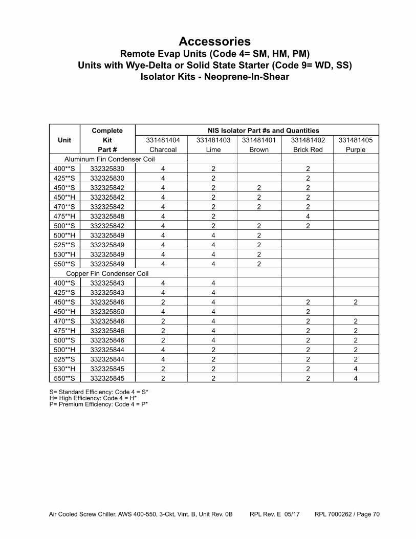
Air Cooled Screw Chiller, AWS 400-550, 3-Ckt, Vint. B, Unit Rev. 0B RPL Rev. E 05/17 RPL 7000262 / Page 70
AccessoriesRemote Evap Units (Code 4= SM, HM, PM)
Units with Wye-Delta or Solid State Starter (Code 9= WD, SS)Isolator Kits - Neoprene-In-Shear
Complete NIS Isolator Part #s and Quantities Unit Kit 331481404 331481403 331481401 331481402 331481405 Part # Charcoal Lime Brown Brick Red Purple Aluminum Fin Condenser Coil 400**S 332325830 4 2 2 425**S 332325830 4 2 2 450**S 332325842 4 2 2 2 450**H 332325842 4 2 2 2 470**S 332325842 4 2 2 2 475**H 332325848 4 2 4 500**S 332325842 4 2 2 2 500**H 332325849 4 4 2 525**S 332325849 4 4 2 530**H 332325849 4 4 2 550**S 332325849 4 4 2 Copper Fin Condenser Coil 400**S 332325843 4 4 425**S 332325843 4 4 450**S 332325846 2 4 2 2 450**H 332325850 4 4 2 470**S 332325846 2 4 2 2 475**H 332325846 2 4 2 2 500**S 332325846 2 4 2 2 500**H 332325844 4 2 2 2 525**S 332325844 4 2 2 2 530**H 332325845 2 2 2 4 550**S 332325845 2 2 2 4
S= Standard Efficiency: Code 4 = S*H= High Efficiency: Code 4 = H*P= Premium Efficiency: Code 4 = P*
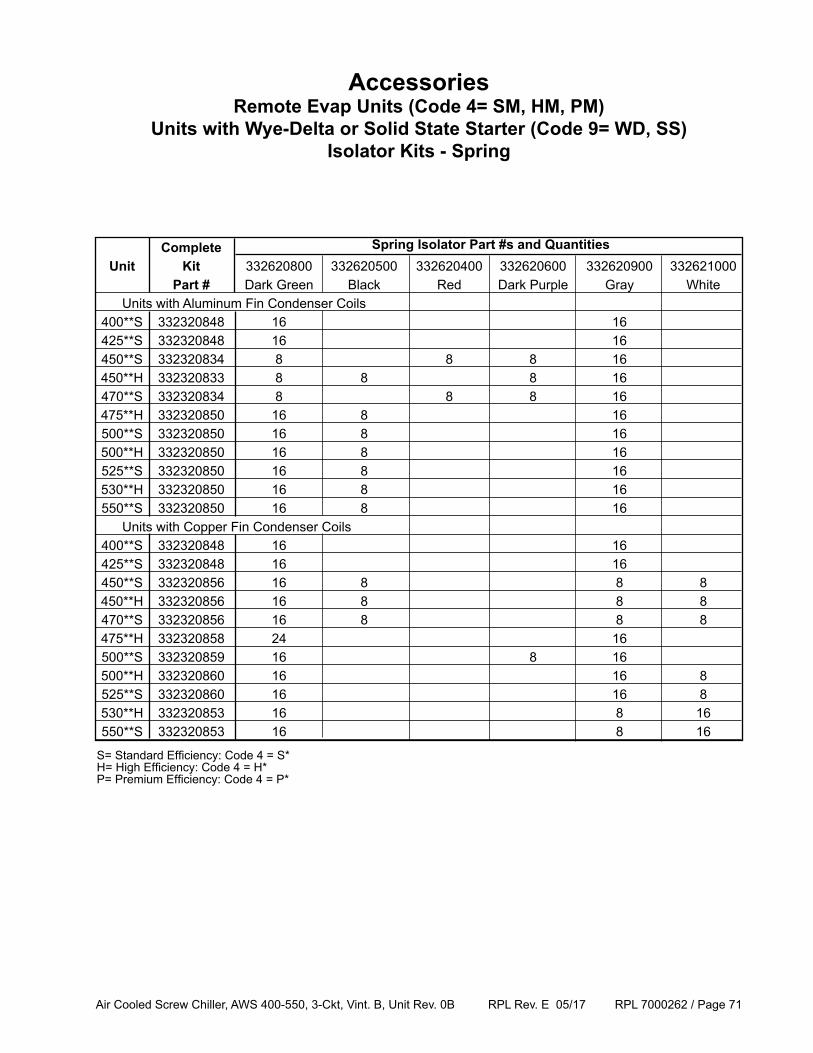
Air Cooled Screw Chiller, AWS 400-550, 3-Ckt, Vint. B, Unit Rev. 0B RPL Rev. E 05/17 RPL 7000262 / Page 71
Complete Unit Kit 332620800 332620500 332620400 332620600 332620900 332621000 Part # Dark Green Black Red Dark Purple Gray White Units with Aluminum Fin Condenser Coils 400**S 332320848 16 16 425**S 332320848 16 16 450**S 332320834 8 8 8 16 450**H 332320833 8 8 8 16 470**S 332320834 8 8 8 16 475**H 332320850 16 8 16 500**S 332320850 16 8 16 500**H 332320850 16 8 16 525**S 332320850 16 8 16 530**H 332320850 16 8 16 550**S 332320850 16 8 16 Units with Copper Fin Condenser Coils 400**S 332320848 16 16 425**S 332320848 16 16 450**S 332320856 16 8 8 8 450**H 332320856 16 8 8 8 470**S 332320856 16 8 8 8 475**H 332320858 24 16 500**S 332320859 16 8 16 500**H 332320860 16 16 8 525**S 332320860 16 16 8 530**H 332320853 16 8 16 550**S 332320853 16 8 16
AccessoriesRemote Evap Units (Code 4= SM, HM, PM)
Units with Wye-Delta or Solid State Starter (Code 9= WD, SS)Isolator Kits - Spring
Spring Isolator Part #s and Quantities
S= Standard Efficiency: Code 4 = S*H= High Efficiency: Code 4 = H*P= Premium Efficiency: Code 4 = P*
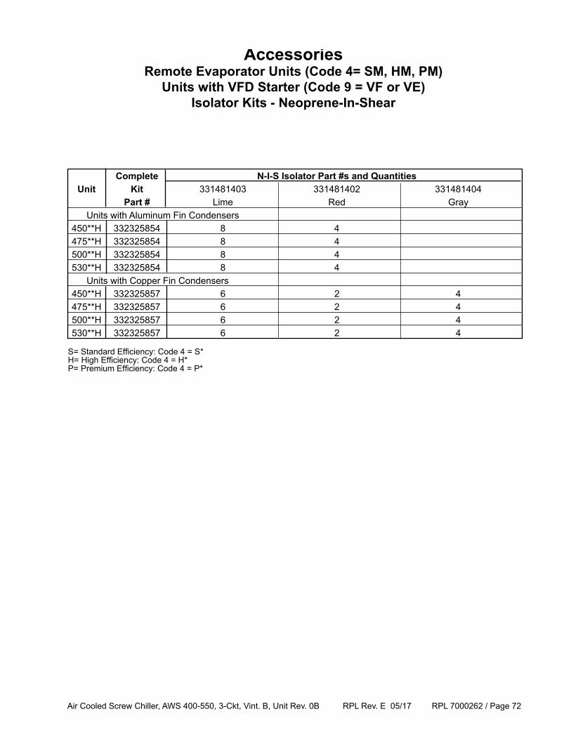
Air Cooled Screw Chiller, AWS 400-550, 3-Ckt, Vint. B, Unit Rev. 0B RPL Rev. E 05/17 RPL 7000262 / Page 72
Complete N-I-S Isolator Part #s and Quantities Unit Kit 331481403 331481402 331481404 Part # Lime Red Gray Units with Aluminum Fin Condensers 450**H 332325854 8 4 475**H 332325854 8 4 500**H 332325854 8 4 530**H 332325854 8 4 Units with Copper Fin Condensers 450**H 332325857 6 2 4 475**H 332325857 6 2 4 500**H 332325857 6 2 4 530**H 332325857 6 2 4
AccessoriesRemote Evaporator Units (Code 4= SM, HM, PM)
Units with VFD Starter (Code 9 = VF or VE) Isolator Kits - Neoprene-In-Shear
S= Standard Efficiency: Code 4 = S* H= High Efficiency: Code 4 = H*P= Premium Efficiency: Code 4 = P*
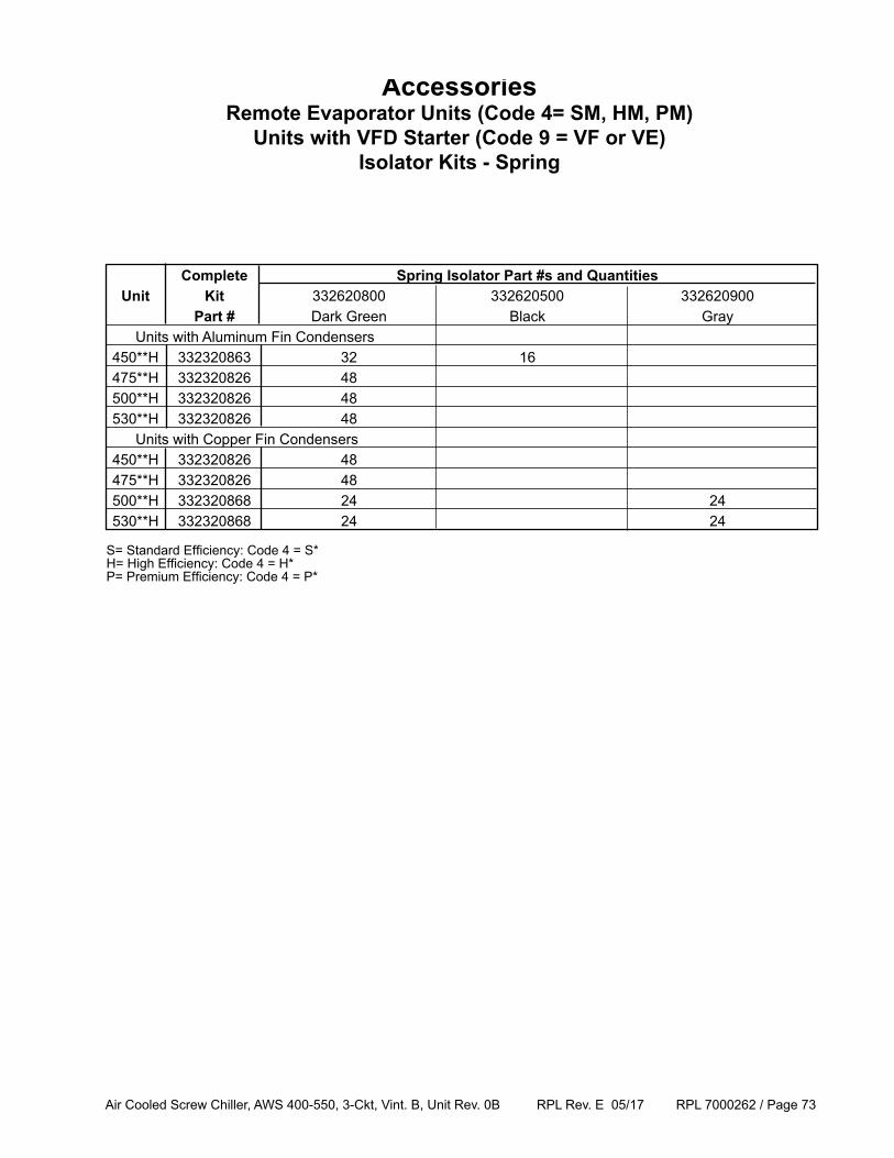
Air Cooled Screw Chiller, AWS 400-550, 3-Ckt, Vint. B, Unit Rev. 0B RPL Rev. E 05/17 RPL 7000262 / Page 73
Complete Spring Isolator Part #s and Quantities Unit Kit 332620800 332620500 332620900 Part # Dark Green Black Gray Units with Aluminum Fin Condensers 450**H 332320863 32 16 475**H 332320826 48 500**H 332320826 48 530**H 332320826 48 Units with Copper Fin Condensers 450**H 332320826 48 475**H 332320826 48 500**H 332320868 24 24 530**H 332320868 24 24
AccessoriesRemote Evaporator Units (Code 4= SM, HM, PM)
Units with VFD Starter (Code 9 = VF or VE) Isolator Kits - Spring
S= Standard Efficiency: Code 4 = S*H= High Efficiency: Code 4 = H*P= Premium Efficiency: Code 4 = P*
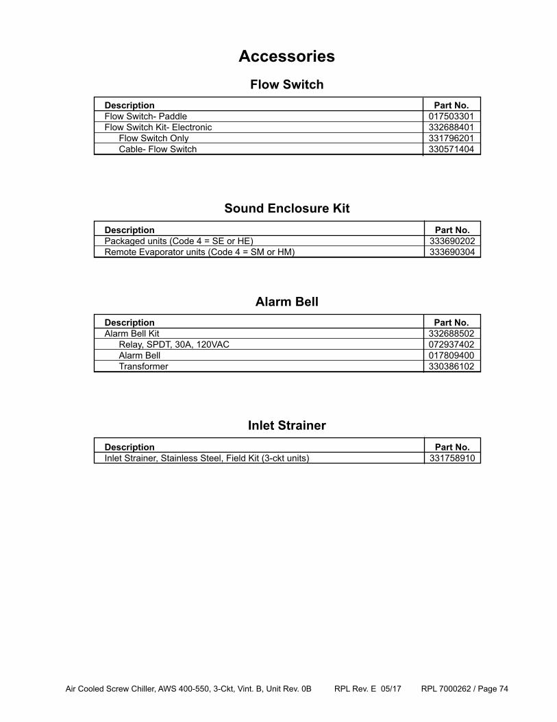
Air Cooled Screw Chiller, AWS 400-550, 3-Ckt, Vint. B, Unit Rev. 0B RPL Rev. E 05/17 RPL 7000262 / Page 74
AccessoriesFlow Switch
Description Part No. Flow Switch- Paddle 017503301 Flow Switch Kit- Electronic 332688401 Flow Switch Only 331796201 Cable- Flow Switch 330571404
Sound Enclosure Kit Description Part No. Packaged units (Code 4 = SE or HE) 333690202 Remote Evaporator units (Code 4 = SM or HM) 333690304
Alarm Bell Description Part No. Alarm Bell Kit 332688502 Relay, SPDT, 30A, 120VAC 072937402 Alarm Bell 017809400 Transformer 330386102
Inlet Strainer Description Part No. Inlet Strainer, Stainless Steel, Field Kit (3-ckt units) 331758910
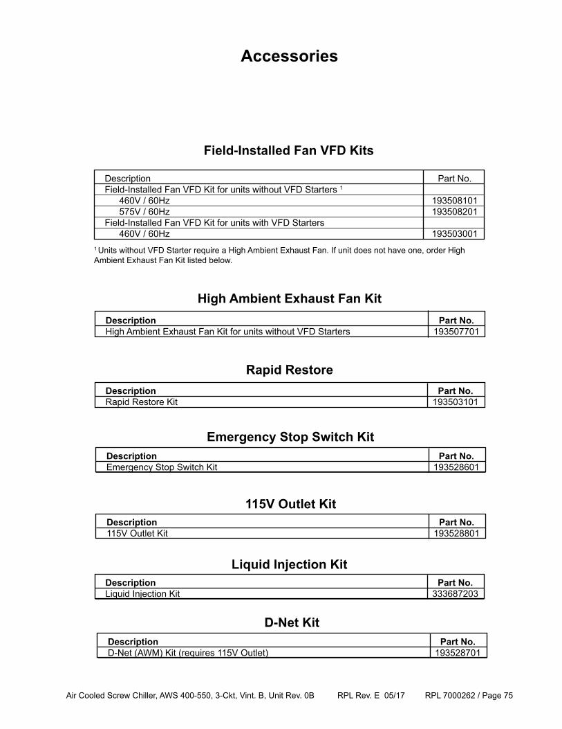
Air Cooled Screw Chiller, AWS 400-550, 3-Ckt, Vint. B, Unit Rev. 0B RPL Rev. E 05/17 RPL 7000262 / Page 75
Accessories
High Ambient Exhaust Fan Kit Description Part No. High Ambient Exhaust Fan Kit for units without VFD Starters 193507701
Rapid Restore Description Part No. Rapid Restore Kit 193503101
Field-Installed Fan VFD Kits
Description Part No. Field-Installed Fan VFD Kit for units without VFD Starters 1
460V / 60Hz 193508101 575V / 60Hz 193508201 Field-Installed Fan VFD Kit for units with VFD Starters 460V / 60Hz 1935030011 Units without VFD Starter require a High Ambient Exhaust Fan. If unit does not have one, order High Ambient Exhaust Fan Kit listed below.
Emergency Stop Switch Kit Description Part No. Emergency Stop Switch Kit 193528601
115V Outlet Kit Description Part No. 115V Outlet Kit 193528801
Liquid Injection Kit Description Part No. Liquid Injection Kit 333687203
D-Net Kit Description Part No. D-Net (AWM) Kit (requires 115V Outlet) 193528701
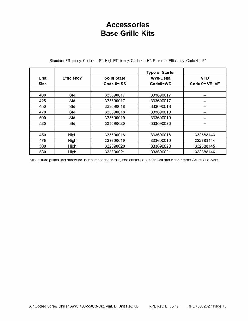
Air Cooled Screw Chiller, AWS 400-550, 3-Ckt, Vint. B, Unit Rev. 0B RPL Rev. E 05/17 RPL 7000262 / Page 76
Type of Starter Unit Efficiency Solid State Wye-Delta VFD Size Code 9= SS Code9=WD Code 9= VE, VF
400 Std 333690017 333690017 -- 425 Std 333690017 333690017 -- 450 Std 333690018 333690018 -- 470 Std 333690018 333690018 -- 500 Std 333690019 333690019 -- 525 Std 333690020 333690020 --
450 High 333690018 333690018 332688143 475 High 333690019 333690019 332688144 500 High 332690020 333690020 332688145 530 High 333690021 333690021 332688146
Standard Efficiency: Code 4 = S*, High Efficiency: Code 4 = H*, Premium Efficiency: Code 4 = P*
AccessoriesBase Grille Kits
Kits include grilles and hardware. For component details, see earlier pages for Coil and Base Frame Grilles / Louvers.
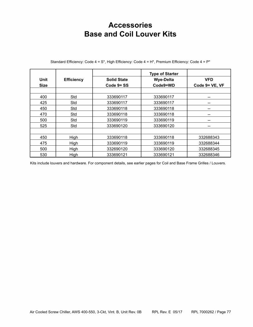
Air Cooled Screw Chiller, AWS 400-550, 3-Ckt, Vint. B, Unit Rev. 0B RPL Rev. E 05/17 RPL 7000262 / Page 77
Type of Starter Unit Efficiency Solid State Wye-Delta VFD Size Code 9= SS Code9=WD Code 9= VE, VF
400 Std 333690117 333690117 -- 425 Std 333690117 333690117 -- 450 Std 333690118 333690118 -- 470 Std 333690118 333690118 -- 500 Std 333690119 333690119 -- 525 Std 333690120 333690120 --
450 High 333690118 333690118 332688343 475 High 333690119 333690119 332688344 500 High 332690120 333690120 332688345 530 High 333690121 333690121 332688346
Standard Efficiency: Code 4 = S*, High Efficiency: Code 4 = H*, Premium Efficiency: Code 4 = P*
Kits include louvers and hardware. For component details, see earlier pages for Coil and Base Frame Grilles / Louvers.
AccessoriesBase and Coil Louver Kits
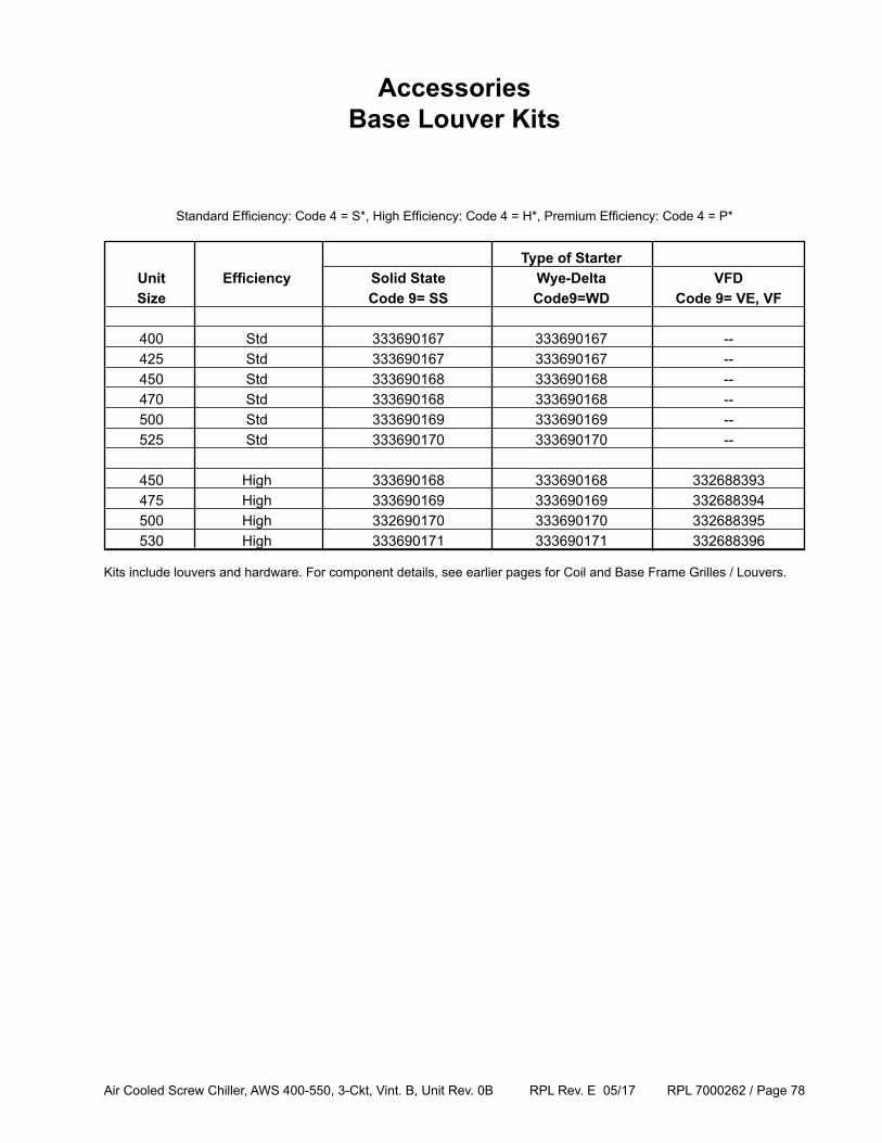
Air Cooled Screw Chiller, AWS 400-550, 3-Ckt, Vint. B, Unit Rev. 0B RPL Rev. E 05/17 RPL 7000262 / Page 78
Type of Starter Unit Efficiency Solid State Wye-Delta VFD Size Code 9= SS Code9=WD Code 9= VE, VF
400 Std 333690167 333690167 -- 425 Std 333690167 333690167 -- 450 Std 333690168 333690168 -- 470 Std 333690168 333690168 -- 500 Std 333690169 333690169 -- 525 Std 333690170 333690170 --
450 High 333690168 333690168 332688393 475 High 333690169 333690169 332688394 500 High 332690170 333690170 332688395 530 High 333690171 333690171 332688396
Standard Efficiency: Code 4 = S*, High Efficiency: Code 4 = H*, Premium Efficiency: Code 4 = P*
AccessoriesBase Louver Kits
Kits include louvers and hardware. For component details, see earlier pages for Coil and Base Frame Grilles / Louvers.
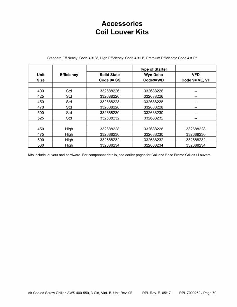
Air Cooled Screw Chiller, AWS 400-550, 3-Ckt, Vint. B, Unit Rev. 0B RPL Rev. E 05/17 RPL 7000262 / Page 79
Type of Starter Unit Efficiency Solid State Wye-Delta VFD Size Code 9= SS Code9=WD Code 9= VE, VF
400 Std 332688226 332688226 -- 425 Std 332688226 332688226 -- 450 Std 332688228 332688228 -- 470 Std 332688228 332688228 -- 500 Std 332688230 332688230 -- 525 Std 332688232 332688232 --
450 High 332688228 332688228 332688228 475 High 332688230 332688230 332688230 500 High 332688232 332688232 332688232 530 High 332688234 322688234 332688234
Standard Efficiency: Code 4 = S*, High Efficiency: Code 4 = H*, Premium Efficiency: Code 4 = P*
AccessoriesCoil Louver Kits
Kits include louvers and hardware. For component details, see earlier pages for Coil and Base Frame Grilles / Louvers.
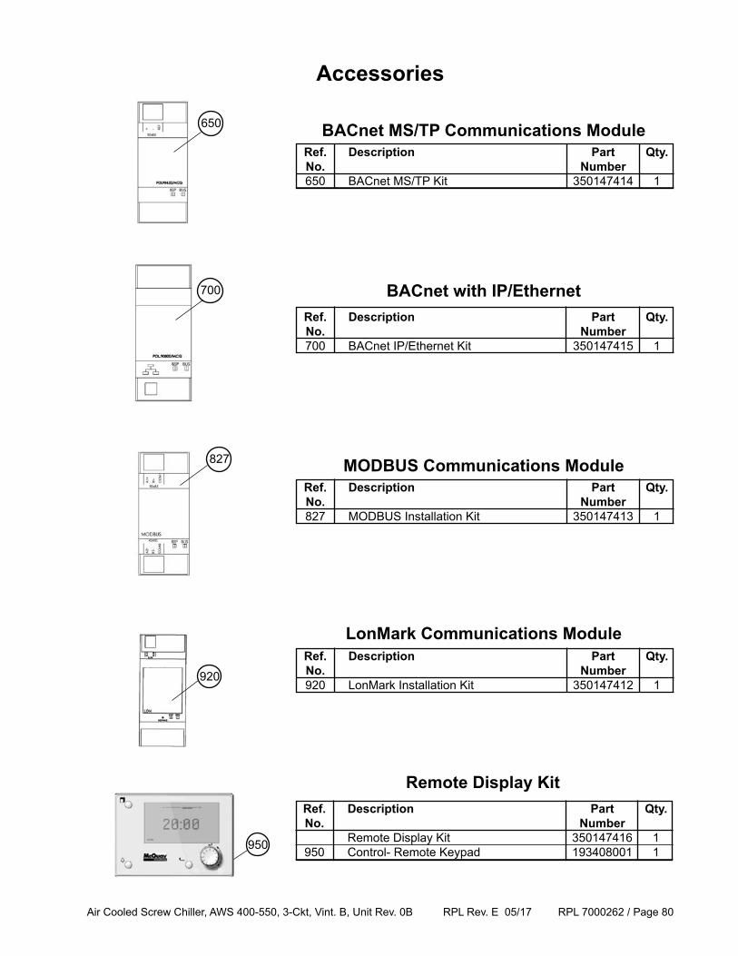
Air Cooled Screw Chiller, AWS 400-550, 3-Ckt, Vint. B, Unit Rev. 0B RPL Rev. E 05/17 RPL 7000262 / Page 80
Ref. Description Part Qty. No. Number Remote Display Kit 350147416 1 950 Control- Remote Keypad 193408001 1
BACnet with IP/Ethernet
Ref. Description Part Qty. No. Number 827 MODBUS Installation Kit 350147413 1
MODBUS Communications Module
Ref. Description Part Qty. No. Number 920 LonMark Installation Kit 350147412 1
LonMark Communications Module
Accessories
Ref. Description Part Qty. No. Number 650 BACnet MS/TP Kit 350147414 1
BACnet MS/TP Communications Module
Remote Display Kit
Ref. Description Part Qty. No. Number 700 BACnet IP/Ethernet Kit 350147415 1
827
700
650
920
950


![[MS-RPL]: Report Page Layout (RPL) Binary Stream Format€¦ · MS-RPL] —. stream report. report page. report report report](https://img.pdfslide.us/doc/110x75/5fd9f7a7a90b7c34145fa364/ms-rpl-report-page-layout-rpl-binary-stream-format-ms-rpl-a-stream-report.jpg)


![[MS-RPL]: Report Page Layout (RPL) Binary Stream Format... · 2017. 8. 16. · [MS-RPL]: Report Page Layout (RPL) Binary Stream Format Intellectual Property Rights Notice for Open](https://img.pdfslide.us/doc/110x75/5fe508334ef13b4c0a6f6ab5/ms-rpl-report-page-layout-rpl-binary-stream-format-2017-8-16-ms-rpl.jpg)