Embed Size (px)
Citation preview

RotorSport UK Ltd
Copyright RotorSport UK Ltd Page 1 of 26 Form F193 Rev2 dated 17.03.15
Aircraft serial no.RSUK/CAVP/
Aircraft 100hr/Annual Repetitive Service Worksheet
NB: Take note of hours/time related actions
Aircraft registration no. G-Worksheet date: Worksheet type: 100HR / ANNUAL (delete as appropriate)
Unique worksheet no. (if required/used):Tsk No. Task Description
Repetition or comments Actions taken & comment Eng’r initial
Licenced Eng’r
Purpose of this worksheet: To be applied for the first 100hrs of operation and every subsequent 100hrs or Annually, whichever occurs sooner, to a Cavalon Pro gyroplane with Woodcomp KW-31 variable pitch propeller. If prior to renewal of the aircraft’s Certificate of Validity, the owner is also referred to the renewal requirement list on the RSUK website. This document covers the Cavalon Pro aircraft with Woodcomp variable pitch propeller, refer to Cavalon Pro Maintenance Manual RSUK0335. Some of the checks and serviceability are ‘on condition’, meaning the Engineer has the responsibility to decide if an item is acceptable for service.Some of the work involved affects CRITICAL PARTS and/or CRITICAL ASSEMBLIES (as identified below) – when working on these items follow only the procedures described in the Maintenance Manual RSUK0335.NOTE! Cowls and covers must be removed to undertake this service. Refer to Cavalon Pro Pilots Handbook RSUK0334 for guidance.The task numbers listed in the left-most column are rationalised i.e. identical on all Cavalon Pro Service Worksheets. The task numbers may not therefore be sequential
Preparatory work
1 Review the aircraft documents (and the list of publications towards the end of this Worksheet) to determine any outstanding, specific or additional requirements to be conducted.
2 Remove the rotor and place on three trestles pending further work. Replace the teeter bolt, shim washers and nut in the teeter tower in their original locations.
Consult Cavalon Pro POH RSUK0334or Cavalon Pro AMM RSUK0335 for technique.Note the use of “dot-marks”
CRITICAL PARTS & ASSEMBLY
3 Clean the aircraft, remove any dirt, dust, loose items. During cleaning inspect for any fluid leaks.
4 Perform an external visual inspection of all cowlings and mast covers. Record any cosmetic damage on the graphic at the end of this document then remove the items. Perform a detailed inspection (no cracks, distortion, missing parts).
Consult RSUK to organise any repairs or replacements required
5 Remove keel-tube cover, leaving loose on tube

RotorSport UK Ltd
Copyright RotorSport UK Ltd Page 2 of 26 Form F193 Rev2 dated 17.03.15
Aircraft serial no.RSUK/CAVP/
Aircraft 100hr/Annual Repetitive Service Worksheet
NB: Take note of hours/time related actions
Aircraft registration no. G-Worksheet date: Worksheet type: 100HR / ANNUAL (delete as appropriate)
Unique worksheet no. (if required/used):Tsk No. Task Description
Repetition or comments Actions taken & comment Eng’r initial
Licenced Eng’r
6 Remove all service covers (external), inspection hatches (internal) and the removable firewall panel. Perform a detailed inspection (no cracks, distortion, missing parts).
Consult RSUK to organise any repairs or replacements required
7 Lift stick gaitor(s) away from the Velcro retention to cockpit floor
8 Release the centre console, lift clear but leave the controls attached.
Consult Cavalon Pro AMM RSUK0335and note the hidden screw accessed through the left wall of the centre-tunnelfor the heater control lever.

RotorSport UK Ltd
Copyright RotorSport UK Ltd Page 3 of 26 Form F193 Rev2 dated 17.03.15
Airframe Inspection
10 Check - Bolt torques – mast fittings Torque-check the M8 countersunk screws to 22Nm (2 pairs). If any visible movement remove screw, re-Loctite 243 and replace tightening to 25Nm+/-3Nm. Second signature required if any screw removed/replaced.
1st inspectionName:Engineer authorisation no:
Sig:……………………………….
2nd inspectionName:Engineer authorisation no:Or, qualified pilot licence no:
Sig:………………………………
Instrument S/No:……………………….
Calibrated until:…………………………
12 Inspect – mast rubber bushings for failure or free play, fastenings for security, and any sign of wear or damage between the upper mast side plates and lower mast. Check bush integrity by pulling the rotor head forwards with a 15Kg load. Movement is 5mm maximum, measured relative to the lowest point of the windscreen surround.
Note that bush fastenings are secured with Loctite 638, which will require heat to remove!
If cracks or deformation found then ground aircraft and call RSUK for advice.
Instrument S/No:……………………….
Calibrated until:…………………………
13 Inspect – upper mast for damage, twisting, buckling or other deformation, or cracks, especially at welded joints.
If cracks or deformation found then ground aircraft and call RSUK for advice.
CRITICAL PARTS & ASSEMBLY
14 Inspect – Condition of keel-tube and security of attachment to composite body(Screws and band-clamp)Check tail-plane horizontal (i.e. keel-tube not twisted)
If cracks or deformation found then ground aircraft and call RSUK for advice.
CRITICAL PARTS & ASSEMBLY

RotorSport UK Ltd
Copyright RotorSport UK Ltd Page 4 of 26 Form F193 Rev2 dated 17.03.15
15 Inspect – keel-tube protection pads(condition and attachment).
Replace if worn – see Cavalon Pro AMM RSUK0335
16 Inspect - External structure of body sound with no cracks, distortion or damage. Pay particular attention to the lower mast area around the air-intake duct.
If cracks or deformation found then ground aircraft and call RSUK for advice.
Undercarriage – main gear and brakes20 Inspect - landing gear spar and
attachments to body for damage or fatigue (cracks & deformation).
If cracks or deformation found then ground aircraft and call RSUK for advice.
21 Inspect – wheel spats general condition, security of mounting and tyre clearance.
22 Inspect – main wheels general condition, correct pressure, condition of tread, correct seating of valve and cap, secure installation, free movement but no play in wheel bearings, presence and condition of creep-mark on tyre/rim
No fabric to show through the tread area. Recommended 0.5mm min treadNo cracks in side-wallsTyre pressure 1.8 to 2.2 bar (latter if heavily loaded). ). Increase to 2.3bar if operating at 560kg MTOW
Tyres OK and pressures recorded as:
Main LH……………..
Main RH……………..
Instrument S/No:……………………….
Calibrated until:…………………………
23 Inspect – wheel brakes for secure installation and correct operation, no fluid leaks from caliper. Condition of pads and brake disc.
24 Inspect - for brake pad wear. Replace as necessary, and if less than 2mm pad remaining. There is a wear indicator slot in the centre of the pad. If the slot is not visible, then the pad should be replaced
If calipers are sticking or uneven wear is found, loosen/turn wheel bolts and check for straightness – if OK retighten. Alternatively, clean brake pad bushes & lubricate calipers around seal
25 Inspect – brake lines for secure installation, no leaks or chafing

RotorSport UK Ltd
Copyright RotorSport UK Ltd Page 5 of 26 Form F193 Rev2 dated 17.03.15
26 Inside a/c examine the centre-console:Inspect – all fastenings (including jam-nuts) secure. All mechanisms move smoothly and correctly without interfrence
27 Service/lube – change brake fluid Recommended at 3years, or when brakes become spongy. Refill from master cylinder with callipers immersed in fluid. If system is spongy after bleeding, check discs for flatness and wheel bolts for straightness.
28 Inspect – brake ratchet pawl for excessive wear. If found, replace.
Teeth of lever must not be visibly deformed or protrude less than 1.5mm.
29 Inspect – condition of and no leaks from coolant hoses attached to water-valve.
30 Refit centre console using Loctite 243 on the screw attaching the heat control to the water-valve.
Undercarriage – nose-wheel
40 Inspect – wheel spat for general condition, security of mounting and tyre clearance
41 Inspect - nose-wheel general condition, correct pressure, condition of tread, correct seating of valve and cap, secure installation, free movement but no play in wheel bearings.
No fabric to show through the tread area. Recommended 0.5mm min treadNo cracks in side-wallsTyre pressure 2.0 to 2.4bar (latter if heavily loaded). ).
Tyre OK and pressure recorded as:
Nose………………….
42 Inspect - nose-wheel fork for general condition, secure installation, freedom of movement, no excessive play, distortion or damage
43 Inspect - nose-wheel rubber damper general condition and correct operation
External lights
50 Op/C check red anti-collision light function and security(fitted to each mainwheel spat)
51 Op/C check strobe function
52 Op/C check nav light function Red to left, green to right, white to rear

RotorSport UK Ltd
Copyright RotorSport UK Ltd Page 6 of 26 Form F193 Rev2 dated 17.03.15
53 Op/C check nose light function
54 Op/C check landing light function and security (fitted in binnacle under nose)
Electrical/instruments
60 Inspect – panel mounting screws secure
61 Inspect - panel connections for security
62 F/C – slip indicator Confirm slip-string undamaged and free-moving
63 Inspect - Confirm all placards readable and in line with Operating Limitations
See Cavalon Pro POH RSUK0334 for placards required (or the CAA publication TADS)
64 Check - aircraft weight and balance No annual check required, but confirm weighing certificate available and matches weight shown on placard
65 Inspect – gel battery for security of mounting, casing leakage and state of charge
If required connect ground-power to fully charge battery in anticipation of tests later in this Worksheet.
If Annual Service/Inspection use a proprietary instrument to confirm battery capacity is at least 80%.
66 Op/C check function of instrument panel lights
67 Op/C check function of cabin light (if fitted)69 Op/C check backup (electric) fuel pump
functionTo check the pitot system under tasks 70-72 it will be necessary to temporarily remove the pitot bleed valve and temporarily block the pipe. Ensure valve replaced after the checks.
70 F/C – Aspen 1000PFD calibration cross-check
Check pitot and static systems as per Cavalon Pro AMM RSUK0335 system checks sect 9Check comparable readings to magnetic compass
71 F/C – ASI calibration Check pitot and static systems as per Cavalon Pro AMM RSUK0335 system checks sect 9

RotorSport UK Ltd
Copyright RotorSport UK Ltd Page 7 of 26 Form F193 Rev2 dated 17.03.15
72 F/C – altimeter calibration Check pitot and static systems as per Cavalon Pro AMM RSUK0335 system checks sect 9
73 F/C – compass calibration Cross check to handheld compass74 F/C Engine instruments
Engine RPM
Engine CHT
Engine Oil temperature
Engine oil pressure
Engine datalogger (914UL only)
The engineer may wish to defer the five checks below until the final ground run checks are conducted (towards the end of this worksheet)
At tick-over compare with hand-held digital tachometer. Readings to be within 100rpm.
Warm-up engine then stop. Using hand-held digital temperature indicator compare surface temperature adjacent to sensor. Readings to be within 10ºC
Warm-up engine then stop. Using hand-held digital temperature indicator compare surface temperature adjacent to sensor. Readings to be within 10ºC
Check zero with engine stationary then rising to a minimum of 2 bar at 4000rpm.Alternatively (and depending on sensor type fitted), temporarily disconnect the cable from the pressure sensor and using a suitable resistor (600-690ohms) apply 12VDC @ 20mA to the signal lead (A6 Yellow/green). The gauge should read FSD. Reconnect the cable.
Optionally, Turbo TCU data (where fitted) may be downloaded for analysis

RotorSport UK Ltd
Copyright RotorSport UK Ltd Page 8 of 26 Form F193 Rev2 dated 17.03.15
75 F/C Rotor rpm gauge (annual) On flight test confirm usual indications at pre-rotate and cruise conditions in the actual take-off configuration – see Cavalon Pro POH RSUK0334 section 5.1)Alternatively, in a safe area, activate the pre rotator. Use a hand held tachometer aimed at the rotor/head & compare readings of rotor rpm to the tacho. Readings to be within 25rpm
76 Op/C – Avionics checks Transponder – Check that mode S code matches G-INFO database. At eachbi-annual inspection a full functional check is required, using an Aeroflex IFR6000 test-set or equivalent to confirm correct transponder function including correlation with a/c altimeter.Radio – confirm PTT buttons cause ‘T’ on panel. (NB: Further checked for transmit and receive quality on Annual flight-test)
Transponder code required to be transmitted:
Actual code transmitted transponder code:
Where possible, print out transponder test report and attach to service docs
Instrument S/No:……………………….
Calibrated until:…………………………
77 Op/C – Fire-warning systemCheck that power-up lamp test, simulated fault and simulated fire-warnings are displayed
See Cavalon Pro AMM RSUK0335
Intentionally blank

RotorSport UK Ltd
Copyright RotorSport UK Ltd Page 9 of 26 Form F193 Rev2 dated 17.03.15
Rotor head
80 Renew main bearing Replace bearing at 1500hrs (no extension permitted). Bearing bolt torque 150Nm+/-20Nm Confirm split pin correctly fittedNOTE: when tightening hub onto backing plate ensure that the clearance between the main gear and bendix gear is minimised from 0.05 to 0.15mmClearance of rotor speed sensor to gear is 1 to 2mm (confirm function via tacho)NOTE: set sideways position of head in rotorbridge before tightening iaw RSUK0335.
CRITICAL PARTS & ASSEMBLY
1st inspectionName:Engineer authorisation no:
Sig:……………………………….
2nd inspectionName:Engineer authorisation no:Or, qualified pilot licence no:
Sig:………………………………
81 Op/C – Ring gear security and bolt attachment
Note any wear patterns
82 Lubricate rotor brake pivot. WD40 or similar
83 Inspect – brake pad for function. Pad replaceable as a service item
84 Op/C – Check roll and pitch trim cylinders for free function and slider damage or excess seal leakage.
Seal service kit is available from RSUK
86 Check, Service/lube – teeter bolt & bearings for damage & wear.
Regrease via nipple on top of rotor (where fitted). Grease with Castrol LM or equivalent If wear or signs of distress, inspect and replace bushes or bolt if required. Clean, regrease & refit.Excess wear is more than 0.5mm of vertical play, bolt to bushes, and will cause rotor vibrationRemoval, clean, inspect and refit is recommended every 100hrs.
CRITICAL PARTS & ASSEMBLY
87 Check, bushes in tower sides. If worn, replace
Small sideways float between hub bar and bushes required for low vibration
CRITICAL PARTS & ASSEMBLY

RotorSport UK Ltd
Copyright RotorSport UK Ltd Page 10 of 26 Form F193 Rev2 dated 17.03.15
88 Service/lube –gimbal joints, check for wear & regrease.
Grease with Castrol LM or equivalent. If wear evident or noticeable looseness, disassemble gimbal joints, check for wear, regrease and reassemble. Torque up bolts to clamp side plates to gimbal block iaw RSUK0335.Strip and inspect recommended every 200hrs of operation
CRITICAL PARTS & ASSEMBLY
89 Inspect – teeter stop plate securely attached to teeter tower and plastic teeter stops securely attached to plate
7mm thick stops
90 Overall check all attachment hardware secure and verify 3-off split pins in place and correctly formed.
Split pins are fitted to main bearing bolt, pitch bolt and roll bolt.This check is required even if no disassembly actions have been conducted.
NB: The teeter-bolt’s split pin is fitted and checked under “Rotor” later in this worksheet
CRITICAL PARTS & ASSEMBLY
1st inspectionName:Engineer authorisation no:
Sig:……………………………….
2nd inspectionName:Engineer authorisation no:Or, qualified pilot licence no:
Sig:………………………………
Rotor Head Controls
100 F/C – rod ends for cracks & freedom of movement both free and at control extremes
101 F/C- rotor head reaches pitch and roll stopsInspect – pitch and roll angles achieved
For limits and methods see Cavalon Pro AMM RSUK0335
102 Inspect – pitch and roll cable attachments to upper mast secure
CRITICAL PARTS & ASSEMBLY
103 Inspect – integrity of earth bond cable attachment to rotor head and mast

RotorSport UK Ltd
Copyright RotorSport UK Ltd Page 11 of 26 Form F193 Rev2 dated 17.03.15
104 Inspect (inside a/c) – all bearings free, all bearing retaining rivets secure, Pushrods, attachments and pivot mountings secure with no damage or chafing. Electrical cables and connectors undamaged.
105 Service/lube – lubricate bearings and ball joints with Ballistol oil
106 Inspect – push/pull cable mountings secure with no chafing.
107 Op/C – for free play in stick control eg bearings or cable wear
108 Inspect – stick forces in pitch and roll For limits and methods see Cavalon Pro AMM RSUK0335
Nose-wheel and Rudder controls110 Op/C – Check pedals for ease of movement Check from each seat
111 Inspect – tension of cable between central control link (mixer unit) and nose-wheel link and re-tension if required. Check turnbuckles secured and no chafing of cables.
See Cavalon Pro AMM RSUK0335.
112 Service/lube – lubricate pedal bearing and sliding block of adjuster with Ballistol oil
113 Inspect – visible rudder cables for frays, corrosion, wear or chafing, and any crimped fittings for signs of movement. Lubricate cables with Ballistol oil.
114 Inspect – all clevis joints at central control link (mixer unit) secured, free to move and no chafing.
115 Inspect – central control link (mixer unit) freedom of movement and main bolt secured.
Access main bolt through rubber plug located centrally underneath body
116 Inspect – security of wire-locking retaining the rudder cables to the keel-tube.
117 Inspect – tail rod-end bearings for looseness and freedom of operation and fitted with snubbing washers. Lubricate control cables with Ballistol oil

RotorSport UK Ltd
Copyright RotorSport UK Ltd Page 12 of 26 Form F193 Rev2 dated 17.03.15
118 Inspect – security and integrity of keel tube in area of attachment to body
Use 10x magnifying glass and suitable illumination to check for cracks in the tube
CRITICAL PARTS & ASSEMBLY
119 Inspect – integrity of tail attachment lugs welded to keel-tube (4-plcs)
Use 10x magnifying glass and suitable illumination to check for cracks on outside of the joint.
CRITICAL PARTS & ASSEMBLY
120 Inspect – tail for security to airframe (4-bolts).
Torque-check the M8 bolts to 12Nm(4-plcs). If any visible movement remove each bolt, re-Loctite 243 and replace, tightening to 15NmSecond inspection required if any bolt removed/replaced.
1st inspectionName:Engineer authorisation no:
Sig:………………………………….
2nd inspectionName:Engineer authorisation no:Or, qualified pilot licence no:
Sig:…………………………………..
Instrument S/No:……………………….
Calibrated until:…………………………
121 Inspect – rudder to tail fastenings. Inspect tail and rudder for signs of composite damage and cleanliness of drain holes.
Torque-check the single M6 or M8 bolt at the top bearing. If any visible movement remove bolt, re-Loctite 243 and replace:M6 test at 8Nm, fit to 10NmM8 test at 10Nm, fit to 12NmSecond inspection required if bolt removed/replaced.
1st inspectionName:Engineer authorisation no:
Sig:…………………………………..
2nd inspectionName:Engineer authorisation no:Or, qualified pilot licence no:
Sig:…………………………………..Instrument S/No:……………………….
Calibrated until:…………………………
122 F/C rudder control cable tension (pedal load check)
For limits and methods see Cavalon Pro AMM RSUK0335
Reading………………………

RotorSport UK Ltd
Copyright RotorSport UK Ltd Page 13 of 26 Form F193 Rev2 dated 17.03.15
Instrument S/No:……………………….
Calibrated until:…………………………
123 Inspect – rudder control angles For limits and methods see Cavalon Pro AMM RSUK0335
Reading………………………Instrument S/No:……………………….
Calibrated until:…………………………
124 Overall check that all control system bolts are correct items, properly fitted and tight
Engine NOTE! All engine checks to be in
accordance with manufacturers manual!
For engine servicing refer to the engine manual issued with the aircraft (Rotax 914F). The full annual engine service is required only when no engine servicing has been carried out in the last 12 months. Otherwise apply ‘on condition’.Servicing must be carried out in line with, and recorded on, the Rotax service schedule contained within the ‘Line Maintenance’ manual for the 914F engine.A record of any work carried-out must be made in the Engine Log Book.
130 Engine service fasteners If the magnetic inspection plug or the crankshaft locking screw plug are disturbed then any wire-locking present must be properly reinstated
131 Wirelocking – ensure present on oil tank drain plug, Oil banjo under engine, carb air filter(s),oil pump
132 Check - external alternator security and V-belt condition/tension
The Rotax Maintenance Manual requires that the V-belt tension is checked every 100hrs and the belt is changed every 5 years. See Section 12-20-00 for assessment of belt tension
Engine, other133 Service/lube – Ensure choke and throttles
move freely from stop to stop, and that turbo detent can be felt correctly. Ensure cables are synchronised.
HSC2000spray grease or equivalent

RotorSport UK Ltd
Copyright RotorSport UK Ltd Page 14 of 26 Form F193 Rev2 dated 17.03.15
134 Inspect – engine mount rubbers for deterioration
Check clearance between airbox and mounting frame.
135Inspect engine bearer bolts for paint stripe, and if moved, re-loctite and tighten to 35Nm. Otherwise check bolt torque. Re-apply paint stripe as required.
Instrument S/No:……………………….
Calibrated until:…………………………
136 Inspect – oil cooler general condition, security of mountings, no leaks or cracks in fittings.
137 Inspect – all oil hoses and pipes for secure installation, no leaks, chafing, hardening of pipes or abrupt direction changes. Check condition of heat-insulating tubes under engine.
138 Inspect – oil thermostat assembly for secure attachment, no cracks or leaks from fittings.
139 Inspect – all coolant hoses for condition and secure installation, no leaks, chafing or porosity.
140 Inspect – condition of heat protection on coolant hose from Cylinder #2.
141 Inspect – coolant radiator for secure installation, cleanliness, leaks or damage
142 Inspect – radiator fan for correct operation, no damage to cage or blades
Fan runs in direction of ram-airflow with engine running.
143 Inspect – coolant overflow tank for correct coolant level, secure installation, no chafing
Use dipstick for coolant level. See Cavalon Pro POH RSUK0334
144 Inspect – exhaust system for general condition, secure installation, no leaks, cracks or loose rivets.Check security of turbocharger installation
Use tap-test to inspect for cracks
145 Inspect – after-muffler clamps for deterioration and secure fitment and that wire-locking in place (2-plcs)
Note that rubber strips are not fitted to Cavalon Pro
146 Inspect – security of earth bond cable between engine frame and keel tube.

RotorSport UK Ltd
Copyright RotorSport UK Ltd Page 15 of 26 Form F193 Rev2 dated 17.03.15
Fuel system
150 Inspect – security of fuel tanks and fuel cross-over tube/clamps. No evidence of leakage in fuel tank compartment.
Fuel tanks are bonded in place with flexible mastic.
152 Service/lube – Drain any water in the fuel tanks via the water drain valve, confirming correct function and closure. Drain crossover tube by removing drain valve only if required to remove significant water or debris from main tanks.After reassembly verify correct operation and sealing of fuel-drain valve
If removed, seal thread with PTFE tape or equivalent, ensuring minimal overlap over the plug end. Wirelock after refitting
1st inspectionName:Engineer authorisation no:
Sig:…………………………………..
2nd inspectionName:Engineer authorisation no:Or, qualified pilot licence no:
Sig:…………………………………..
153 Service/lube – Change fuel filters Recommended every 200hrs, or more frequently if fuel contamination suspected
154 Inspect – fuel cap for condition, tightness, correct function and cleanliness of vent hole.
155 Inspect – breather pipe for blockage.
156 Inspect – in area protected by removable firewall and in engine compartment check all fuel lines for condition, secure installation, presence of fire-protective sleeve, no chafing or kinks.
Check ends of hoses where expanded over fittings.
157 Inspect – security and function of electric fuel pump(s)
Function determined by sound on operation
158 Op/C – correct operation and security of fuel shut-off valve, correct operation of safety-guard
159 Op/C – functionality of fuel gauge ie that the reading is consistent with that shown on the tank dip-stick
160 Op/C – functionality of low-fuel warning lamp
Drain fuel (by siphon or by electrical pump) until level below sensor in RH tank (nom 5 litres).

RotorSport UK Ltd
Copyright RotorSport UK Ltd Page 16 of 26 Form F193 Rev2 dated 17.03.15
Pre rotator 170 Inspect – security of gearbox and
pneumatic pipe to pre-rotator clutch.171 Inspect- drive shafts for bend or damage.
No bearing play, corrosion or cracks in flanges of u/j couplings
Clean as required (use a kitchen plastic scouring pad) and protect with oil or chain wax
172 Op/C – Cycle by hand thru full range –check drive shaft joints for free movement and bearings for play etc.
173 Inspect – security of pneumatic cylinder (on rotor head)
174 Inspect – Bendix to ring-gear engagement. Adjust if necessary
See Cavalon Pro AMM RSUK0335
175 Service/lube – Lubricate Bendix gear & spiral gear
WD40 or similar only. Do not use grease!
176 Service/lube – clean then apply a minimal smear of light oil or WD40 to ring gear teeth
177 Service/lube – sliding shaft coupling with grease and verify free movement
Castrol LM or equivalent
178 Service/lube –uppermost drive shaft protected with Waxoyl
Apply with brush, do not spray.

RotorSport UK Ltd
Copyright RotorSport UK Ltd Page 17 of 26 Form F193 Rev2 dated 17.03.15
Trim System, Rotor Brake & Pneumatics
180 Inspect – all hoses for leaks and slave cylinder for looseness
181 Change (or dry out) compressor water absorber.
Recommended to be changed at 500hrs
182 Inspect – compressor. Listen for undue noises in operation and confirm automatic cut-out at 8 bar system pressure. If continuous running or <7bar achieved either find air-leak or replace compressor
Note pressure obtained
183
Op/C – Full functional check, pneumatic system – refer as required to the maintenance manual for fault finding and rectification, and a more comprehensive understanding of the test background.
REPEAT TEST FOR LEFT STICK (IF FITTED TO AIRCRAFT)
In the ‘Brake’ position, engage brake, confirm operation, and that function is acceptable. Pressurise to maximum. Change to flight – check for 8 sec max to release air from brake system. In ‘Flight’ position check that trim goes on and off in same direction as button.In ‘Flight’ position move stick fully forward. Depress pre rotator button.Ensure the rotor head cylinder engages, and pump runs – and when the stick is pulled back the pump stops. Return the stick to the front, release pre rotator and confirm that pressure is applied to trim and stick comes back slightly.Press right roll and ensure stick then moves right and bar indicator does the same. Repeat to left, then centralise indicator – and check for stick return to mid position.In ‘Brake’ position, put 3 bar pressure on and ensure pre rotator does not function Press the ‘Interlock release button’ and ensure that pre rotator functions (movement of head cylinder) with brake engaged.

RotorSport UK Ltd
Copyright RotorSport UK Ltd Page 18 of 26 Form F193 Rev2 dated 17.03.15
Woodcomp KW-31 Propeller NOTE! All propeller checks to be in
accordance with manufacturers manual!
For propeller servicing refer to the Woodcomp User Manual UM-05 EN issued with the aircraft. Servicing must be carried out in line with the Woodcomp service schedule contained within the propeller manual. A record of any work carried-out must be made in the Propeller Log Book.Note that in addition to regular inspections at 100hour intervals there are requirements for Medium Repair after 700hours (or 2 years) service and Overhaul after 1400hours (or 4 years) service.
190 Check – propeller blades for cracks, delamination or impact damage.
Minor damage may be repaired as defined in Woodcomp User Manual Section 19
191 Check – security of propeller protection tape.
May be replaced as defined in Woodcomp User Manual Section 19
192 Check – satisfactory condition/function of the tab washers between mounting boltsand gearbox flange (6-plcs).
If replacement is required first tighten the bolts (progressively) to 22Nm before setting the tab locking.
193 Check – security of brush box fasteners and condition of brushes
Minimum engagement of brush in housing 4mm. (Original length 14mm)
Instrument S/No:……………………….
Calibrated until:…………………………
194 Check the condition of the spinner and after refitting check the security of the retaining screws
15 screws around perimeter
195 F/C - tracking to manufacturers recommendations
(none required at the time of writing)

RotorSport UK Ltd
Copyright RotorSport UK Ltd Page 19 of 26 Form F193 Rev2 dated 17.03.15
196 F/C – with the controller set into manual mode and the propeller set in the fully fine pitch position, measure prop blade pitch angle. Adjust the propeller to the fully coarse pitch position, visually verifying that all blades move correctly and simultaneously and that the controller LED2 (Max) warning light functions correctlyReturn the propeller to the fully fine position, verifying correct function of the LED1 (Min) warning light.
Nominal pitch setting is 10.5deg Fine to 18.5deg Coarse relative to the propeller hub.The pitch angles may be confirmed by measurement across the concave surface at the edge of the yellow band on the end of the prop blade:
Recommend pitch to be within 0.5deg of each other.
Backlash in blade angle must be minimal
Blade 1………………..…..
Blade 2……………………
Blade 3……………………
Hub datum
Instrument S/No:……………………….
Calibrated until:…………………………
RotorCavalon Pro gyroplanes have a variant of RotorSystemII in which the blades have reduced angle of incidence (RotorSystem II 8.4m RAO). Identification is by red end-caps and black clamping profile.
These rotor blades are lifed at 2,500hrs.The rotor must not be replaced with a different type.Note blades, hub-bars and clamping profile are marked with serial numbers that must match on re-assembly.
200 The rotor should already be removed from the aircraft.Remove rotor blades from hub bar Clean carefully and degrease the inspection area, noting any evidence of fretting (a black dust or residue). Then check blade underside around outboard bolt hole area (to +/-60mm axially along the blade) for cracks with a x5 magnifier.Check blades for straightness axially in the area of the outboard bolt hole with a 1m straight edge.
This check is carried out every 500hrs and is not required annually.No cracks permissible. No bend permissible. If any evidence of fretting is noted, contact RSUK for advice/action required.
Do not disassemble the hub-bar bolts (4-off with nyloc nuts) or teeter stop mounting bolts (4-off with Binx nuts)
CRITICAL PARTS & ASSEMBLY

RotorSport UK Ltd
Copyright RotorSport UK Ltd Page 20 of 26 Form F193 Rev2 dated 17.03.15
201 Inspect blades to manufacturers recommendations for any damage, splits etc.
Repair only as Cavalon Pro AMM RSUK0335
CRITICAL PARTS & ASSEMBLY
202 Inspect – condition of rotor blades, hub bars, condition and torque of hub-bar bolts and teeter block bolts.
Hub bar bolts (4-off) have M8 nyloc nuts (25Nm)Teeter-block bolts (4-off) have Binx nuts (20Nm)Inspect blades to manufacturers recommendations for any damage, splits etc. Repair only as Cavalon Pro AMM RSUK0335
CRITICAL PARTS & ASSEMBLY
203 Check – rotor blade nut torque The rotor blade bolts are of different lengths. Ensure correct location fitment.M8 Bolt/nyloc nut torque 25Nm. Refer to Section 9 “General Notes” of the Maintenance Manual for re-usage of nyloc nuts
CRITICAL PARTS & ASSEMBLY
204 Refit rotor to aircraft ensuring that relative locations of shim washers correct (via dot marks).Regrease teeter bolt
Cavalon Pro POH RSUK0334Castrol LM grease or equivalent
CRITICAL PARTS & ASSEMBLY
205 Confirm teeter bolt nut is hand tight (1-2Nm max) and split-pin fitted and correctly formed.
CRITICAL PARTS & ASSEMBLY
1st inspectionName:Engineer authorisation no:
Sig:…………………………………..
2nd inspectionName:Engineer authorisation no:Or, qualified pilot licence no:
Sig:…………………………………..
Body and doors
210 Inspect – doors for cracks, damage or distortion preventing easy opening and closing

RotorSport UK Ltd
Copyright RotorSport UK Ltd Page 21 of 26 Form F193 Rev2 dated 17.03.15
211 Inspect – door hinges for security, cracks or fractures
212 Inspect – plexiglass surfaces (3-plcs) for cracks, cleanliness and obscurity. Determine if acceptable for flight
213 F/C – opening and closing operation, and effectiveness of door locks
See Cavalon Pro AMM RSUK0335 for load values
214 F/C – free and correct operation of sliding side windows (DV windows)
215 F/C – security and free movement of rotary window vents
Pitot-static system
220 Inspect – pitot tube general condition, secure installation, no obstructions. Check correct function of heater (Caution: risk of burn injury)
221 Inspect – static ports open, placards installed, no obstructions
Other
225 Inspect – Cabin ventilation – ensure port under body is free from obstruction
226 F/C – Cabin heat (if fitted) – ensure water-valve opens and closes on cockpit demand and that electric fan starts on selection of “hot”.
227 Inspect – seat mountings secure and backrest adjustment correct operation
228 Inspect – all seat belt attachment points for tightness and security
229 Inspect – headset connector plate in good condition and headset hanger secure
230 Inspect – external radio antenna, check for damage and security.
Fitted centrally on the underbody
231 Inspect – external transponder antenna, check for damage and security
Fitted to the rhs of the underbody.
232 Inspect; bearing temp indicator and OAT indicators for clear display
234 Overall check that all cockpit and panel fittings are secure

RotorSport UK Ltd
Copyright RotorSport UK Ltd Page 22 of 26 Form F193 Rev2 dated 17.03.15
235 Inspect, condition and weight of fire-extinguisher canister
Enter current weight on label fitted to canister. If less than the original declared weight by more than 5% the extinguisher must be replaced.
Final ground run checks prior to release Follow safe practice, aircraft tied-down and with qualified operator or pilot only.
250 Re-install the removeable firewall panel
251 Re-install keel-tube cover
252 Check all service pipes and cables around engine are secured
253 Op/C – full functional check of engine start and run up to normal operating temperature
254 Op/C- with propeller set to fully fine ensure engine achieves at least 5,400rpm on one fuel pump only, and with both pumps running.
Propeller may be damaged if in fully coarse pitch during this test RPM achieved:………………….
255 OP/C - complete mag drop checks at 4,000rpm
See Cavalon POH RSUK0334 for limitsMag drop L:……………………..
Mag drop R:……………………..
256 Confirm-‘Gen’ light is on when engine not running, and off (or flickering gently) when running at above 2000rpm.
257 Confirm-‘Gen2’ light is on when engine not running, and off (or flickering gently) when running at above 2000rpm.
If external generator fitted
258 Confirm low fuel lamp is not lit (providing the fuel covers the sensor)
Low fuel indication at approx. 5 litres remaining
259 Inspect – instruments for measurements consistent with ambient conditions
260 Observing Rotax shut-down requirements stop engine.Inspect - Power plant and coolant system for leaks
Finalization work
270 Carry-out a tool and loose article check
RotorSport UK Ltd
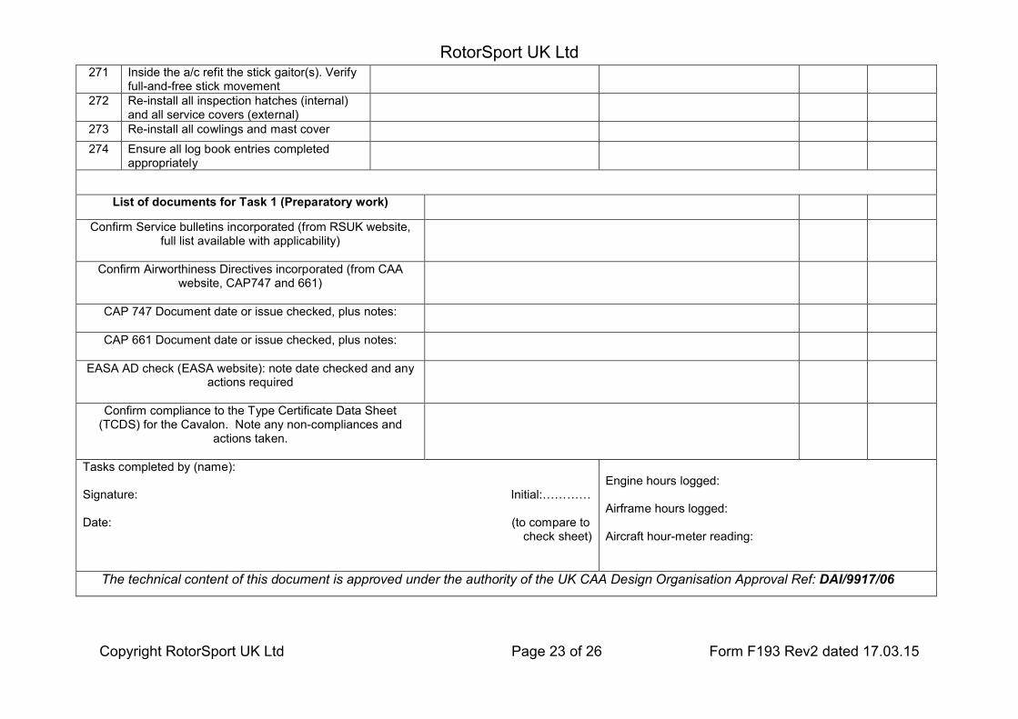
Copyright RotorSport UK Ltd Page 23 of 26 Form F193 Rev2 dated 17.03.15
271 Inside the a/c refit the stick gaitor(s). Verify full-and-free stick movement
272 Re-install all inspection hatches (internal) and all service covers (external)
273 Re-install all cowlings and mast cover
274 Ensure all log book entries completed appropriately
List of documents for Task 1 (Preparatory work)
Confirm Service bulletins incorporated (from RSUK website, full list available with applicability)
Confirm Airworthiness Directives incorporated (from CAA website, CAP747 and 661)
CAP 747 Document date or issue checked, plus notes:
CAP 661 Document date or issue checked, plus notes:
EASA AD check (EASA website): note date checked and any actions required
Confirm compliance to the Type Certificate Data Sheet (TCDS) for the Cavalon. Note any non-compliances and
actions taken.
Tasks completed by (name):
Signature: Initial:…………
Date: (to compare to check sheet)
Engine hours logged:
Airframe hours logged:
Aircraft hour-meter reading:
The technical content of this document is approved under the authority of the UK CAA Design Organisation Approval Ref: DAI/9917/06

RotorSport UK Ltd
Copyright RotorSport UK Ltd Page 24 of 26 Form F193 Rev2 dated 17.03.15
Certificate of Release to Service: The work recorded above (all pages) has been completed to my satisfaction and in that respect the aircraft is considered fit for flight.
Name:
Signature: Initial:
Date (to compare to check sheet
CAA Authorisation Ref No:
Comments:
Note to Engineer; remember to reference this worksheet and RSUK0335 within the logbooks, together with your CAA authorisation code. Work undertaken may be noted on this worksheet, or if required on another sheet (such as F093) also referenced in the logbook. Modifications undertaken must be noted with their MC approval no. Check the back pages to complete these too for modifications, service bulletins, ADs, etc.

RotorSport UK Ltd
Copyright RotorSport UK Ltd Page 25 of 26 Form F193 Rev2 dated 17.03.15
Any cosmetic damage noted on first inspecting the aircraft should be marked on this graphic and brought to the owner’s attention

RotorSport UK Ltd
Copyright RotorSport UK Ltd Page 26 of 26 Form F193 Rev2 dated 17.03.15
Appendix
Requirements for certifying signatures/initials on this worksheet
With the exception of “Permitted Pilot Maintenance” (see the relevant RSUK Aircraft Maintenance Manual and CAA publication CAP 733), all maintenance work on RSUK gyroplanes must be certified by a CAA Authorised Person (a Licenced Engineer).
Case 1: for work not involving engine controls, or flying controls, or vital structural points
The person(s) performing the work should complete the worksheet columns as below: If the person completing “Eng’r” does not have Licenced Engineer authorisation there must be a second initial by a CAA authorised person in each
adjacent “Licenced Engineer” cell, denoting acceptance of the task specified. If the person has Engineer authorisation the “Eng’r” cell should be struck out and a single entry of initials made in the Licenced Eng’r certifier cell
Case 2: for work where engine controls, or flying controls, or vital structural points are disturbed, where a duplicate inspection is required (and shown in the worksheet).
The person(s) performing the work should complete the worksheet columns as shown above and repeated below: If the person completing “Eng’r” does not have Licenced Engineer authorisation there must be a second initial by an CAA authorised person in each
adjacent “Licenced Eng’r” cell, denoting acceptance of the task specified. If the person has Licenced Engineer authorisation the “Eng’r” cell should be struck out and a single entry of initials made in the Licenced Eng’r cell
In addition to the above there is a requirement for inspection, then duplicate inspection (by an independent person) of the finished task: The licenced engineer certifying the task must enter his name, CAA authorisation number, and full signature under “1st inspection”. The independent second person must enter his name, CAA authorisation number or Pilots Licence number, and full signature under “2nd inspection”.
This second person must be suitably qualified and may be: another licenced or CAA authorised engineer a qualified gyroplane pilot. In this case the pilot must append his Pilot’s Licence number to his signature.
It is the second signatory’s responsibility to ensure he/she understands the task and what it is they are inspecting and signing for.
Verification of Initials, Signature and AuthorisationThe person performing the work must complete the “Tasks completed by” statement towards the end of the worksheet.The licenced engineer must complete and sign the “Maintenance Release” on the last page of the Worksheet.


![Repetitive Provisions (61.120) [Enmiendas]](https://img.pdfslide.us/doc/110x75/5695cf181a28ab9b028c93a4/repetitive-provisions-61120-enmiendas.jpg)