Embed Size (px)
Citation preview
Rotational Mechanical Systems
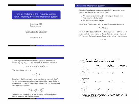
Unit 2: Modeling in the Frequency DomainPart 6: Modeling Rotational Mechanical Systems
Engineering 5821:Control Systems I
Faculty of Engineering & Applied ScienceMemorial University of Newfoundland
January 22, 2010
ENGI 5821 Unit 2, Part 6: Modeling Rotation Mechanical Systems
Rotational Mechanical Systems
Rotational mechanical systems are modelled in almost the sameway as translational systems except that...
We replace displacement, x(t) with angular displacementθ(t); Angular velocity is ω(t)
We replace force with torque
For a force F acting on a body at point P, torque is defined as,
T = FR sinφ
where R is the distance from P to the body’s axis of rotation and φis the angle the force makes to the ray from the axis of rotation toP. Hence, if the force is perpendicular to the axis of rotation then,
T = FR
Rotational Mechanical Systems Gears
A rotating body can be considered a system of particles withmasses m1, m2, m3, . . .. The moment of inertia is defined as,
J = m1R21 + m2R
22 + m3R
23 + · · ·
The total kinetic energy is,
K =1
2Jω2
Recall that the kinetic energy for a translational system is 12mv2.
So J is analagous to mass in translational motion. Also, similar tothe equation F = ma in translational systems, we can relate torqueand angular acceleration,
T (t) = Jdω
dt= J
d2θ
dt2
We define the components of our rotational system as springs,viscous dampers, and rotating masses.
ENGI 5821 Unit 2, Part 6: Modeling Rotation Mechanical Systems
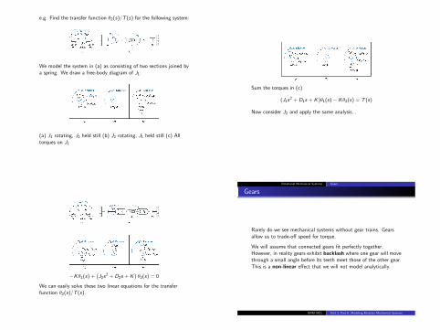
e.g. Find the transfer function θ2(s)/T (s) for the following system:
We model the system in (a) as consisting of two sections joined bya spring. We draw a free-body diagram of J1:
(a) J1 rotating, J2 held still (b) J2 rotating, J1 held still (c) Alltorques on J1
Sum the torques in (c)
(J1s2 + D1s + K )θ1(s)− Kθ2(s) = T (s)
Now consider J2 and apply the same analysis...
−Kθ1(s) +(J2s
2 + D2s + K)θ2(s) = 0
We can easily solve these two linear equations for the transferfunction θ2(s)/T (s).
Rotational Mechanical Systems Gears
Gears
Rarely do we see mechanical systems without gear trains. Gearsallow us to trade-off speed for torque.
We will assume that connected gears fit perfectly together.However, in reality gears exhibit backlash where one gear will movethrough a small angle before its teeth meet those of the other gear.This is a non-linear effect that we will not model analytically.
ENGI 5821 Unit 2, Part 6: Modeling Rotation Mechanical Systems
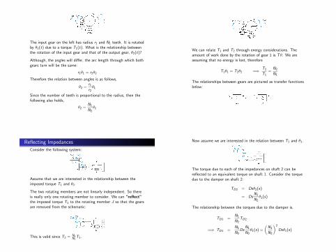
The input gear on the left has radius r1 and N1 teeth. It is rotatedby θ1(t) due to a torque T1(t). What is the relationship betweenthe rotation of the input gear and that of the output gear, θ2(t)?
Although, the angles will differ, the arc length through which bothgears turn will be the same:
r1θ1 = r2θ2
Therefore the relation between angles is as follows,
θ2 =r1r2θ1
Since the number of teeth is proportional to the radius, then thefollowing also holds,
θ2 =N1
N2θ1
We can relate T1 and T2 through energy considerations. Theamount of work done by the rotation of gear 1 is Tθ. We areassuming that no energy is lost, therefore
T1θ1 = T2θ2 =⇒ T2
T1=
N2
N1
The relationships between gears are pictured as transfer functionsbelow:
Reflecting Impedances
Consider the following system:
Assume that we are interested in the relationship between theimposed torque T1 and θ2.
The two rotating members are not linearly independent. So thereis really only one rotating member to consider. We can “reflect”the imposed torque T1 to the rotating member J so that the gearsare removed from the schematic:
This is valid since T2 = N2N1
T1.
Now assume we are interested in the relation between T1 and θ1.
The torque due to each of the impedances on shaft 2 can bereflected to an equivalent torque on shaft 1. Consider the torquedue to the damper on shaft 2:
TD2 = Dsθ2(s)
= DsN1
N2θ1(s)
The relationship between the torques due to the damper is,
TD1 =N1
N2TD2
=⇒ TD1 =N1
N2Ds
N1
N2θ1(s) =
(N1
N2
)2
Dsθ1(s)
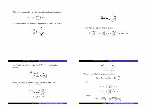
The general pattern for the reflectance of impedances is as follows:
Tdest =
(Ndest
Nsrc
)2
ZMθdest
In this manner we can reflect all impedances on shaft 2 to shaft 1:
This system can be modelled as follows,(Js2
(N1
N2
)2
+ Ds
(N1
N2
)2
+ K
(N1
N2
)2)θ1(s) = T1(s)
Rotational Mechanical Systems Gears
e.g. Find the transfer function θ2(s)/T1(s) for the followingsystem,
Since the output is defined as θ2(s) we should reflect theimpedances from shaft 1 onto shaft 2:
ENGI 5821 Unit 2, Part 6: Modeling Rotation Mechanical Systems
Rotational Mechanical Systems Gears
We can now write the equation of motion:
(Je + De + K2) θ2(s) = T1(s)N2
N1
where,
Je = J1
(N2
N1
)2
+ J2
De = D1
(N2
N1
)2
+ D2
Therefore
G (s) =θ2(s)
T1(s)=
N2/N1
Jes2 + Des + K2
ENGI 5821 Unit 2, Part 6: Modeling Rotation Mechanical Systems
Rotational Mechanical Systems Gears
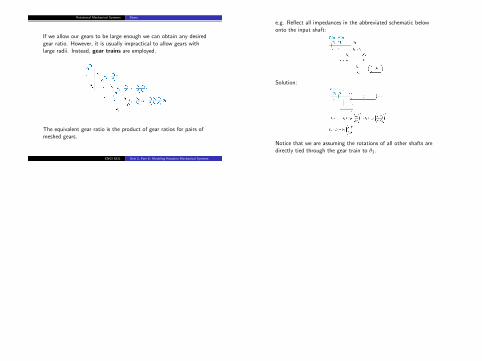
If we allow our gears to be large enough we can obtain any desiredgear ratio. However, it is usually impractical to allow gears withlarge radii. Instead, gear trains are employed.
The equivalent gear ratio is the product of gear ratios for pairs ofmeshed gears.
ENGI 5821 Unit 2, Part 6: Modeling Rotation Mechanical Systems
e.g. Reflect all impedances in the abbreviated schematic belowonto the input shaft:
Solution:
Notice that we are assuming the rotations of all other shafts aredirectly tied through the gear train to θ1.