Embed Size (px)
Citation preview
Trelleborg SeAlINg SolUTIoNS
yoUr pArTNer for SeAlINg TechNology
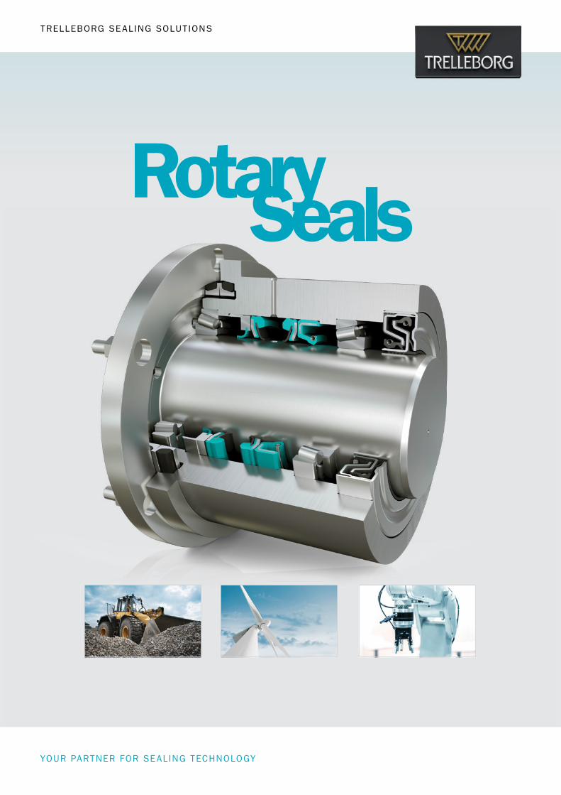
RotarySeals

2 • TRELLEBORG SEALING SOLUTIONS Latest information available at www.tss.trelleborg.com • Edition June 2018
ISO 9001:2008 ISO/TS 16949:2009
Your Partner for Sealing Technology
Trelleborg Sealing Solutions is a major international developer, manufacturer and supplier of seals, bearings and molded components in polymers. We are uniquely placed to offer dedicated design and development from our market-leading product and material portfolio: a one-stop-shop providing the best in elastomer, silicone, thermoplastic, PTFE and composite technologies for applications in aerospace, industrial and automotive industries.
With 50 years of experience, Trelleborg Sealing Solutions engineers support customers with design, prototyping, production, test and installation using state-of-the-art design tools. An international network of over 70 facilities worldwide includes over 20 manu- facturing sites, strategically-positioned research and development centers, including materials and development laboratories and locations specializing in design and applications.
Developing and formulating materials in-house, we utilize the resource of our material database, including over 2,000
proprietary compounds and a range of unique products.Trelleborg Sealing Solutions fulfills challenging service requirements, supplying standard parts in volume or a single custom-manufactured component, through our integrated logistical support, which effectively delivers over 40,000 sealing products to customers worldwide.
Facilities are certified to ISO 9001:2008 and ISO/TS 16949:2009. Trelleborg Sealing Solutions is backed by the experience and resources of Trelleborg Group, one of the world’s foremost experts in polymer technology.
The information in this brochure is intended to be for general reference purposes only and is not intended to be a specific recommendation for any individual application.
The application limits for pressure, temperature, speed and media given are maximum values determined in laboratory conditions. In application, due to the interaction of operating
parameters, maximum values may not be achieved. It is vital therefore, that customers satisfy themselves as to the suitability of product and material for each of their individual
applications. Any reliance on information is therefore at the user‘s own risk. In no event will Trelleborg Sealing Solutions be liable for any loss, damage, claim or expense directly
or indirectly arising or resulting from the use of any information provided in this brochure. While every effort is made to ensure the accuracy of information contained herewith,
Trelleborg Sealing Solutions cannot warrant the accuracy or completeness of information.
To obtain the best recommendation for a specific application, please contact your local Trelleborg Sealing Solutions marketing company.
This edition supersedes all previous brochures. This brochure or any part of it may not be reproduced without permission.
® All trademarks are the property of Trelleborg Group. The turquoise color is a registered trademark of Trelleborg Group. © 2018, Trelleborg Group. All rights reserved.
Rotary Seals
TRELLEBORG SEALING SOLUTIONS • 3Latest information available at www.tss.trelleborg.com • Edition June 2018
6 Introduction
22 Overview Seal Design
31 Radial Oil Seal
33 General Seal Description
35 Design Instructions: Shaft
37 Design Instructions: Housing Bore
38 Material Recommendations
41 Working Parameters
47 Installation Instructions
48 Standard Radial Oil Seal
49 Type TRA
57 Type TRE
64 Type TRC
67 Type TRD
69 Type TRB
73 Type TRF
75 Non Standard Radial Oil Seals
76 Type TRU – Medium Pressure Oil Seal
79 Type TRP – Medium Pressure Oil Seal
81 Type TRQ – Medium-high Pressure Oil Seal
83 Type HP20 – High Pressure Oil Seal
88 Type TRK – Medium Grease
91 Type TRG – Medium Grease
94 Turbo Seals with Hydrodynamic Sealing Aids
96 Rotary and Axial Seal Combination
98 Type TRJ/TRL
113 Cassette Seal
115 General Description
115 System 500
116 System 2000
117 System 3000
118 System 5000
119 System CLS 1500
122 Materials
123 Application
126 Installation
128 Type APJ – Combined Oil Seal
Contents
ROTARY SEALS · Rotary Seals
4 • TRELLEBORG SEALING SOLUTIONS Latest information available at www.tss.trelleborg.com • Edition June 2018
131 End Covers
133 General Description
133 Type YJ 38
137 Type YJ 39
139 Shaft Repair Kit
141 General Description
143 Installation Recommendation – Metric Sizes
145 Installation Recommendation – Inch Sizes
149 Forsheda®V-Ring
151 General Description
152 Materials
155 Installation
158 V-Ring Type A
161 V-Ring Type S
163 V-Ring Type L/LX
166 V-Ring Type RM/RME
171 V-Ring Type AX
173 GAMMA Seal
175 General Description
179 Type TBP/RB
182 Type TBR/9RB
185 Turcon®Roto L
187 General Description
191 Turcon®Varilip®PDR
193 Introduction
194 Product Range
196 Materials
198 Operating Conditions
205 Design Guidelines
207 Installation Requirements
207 Packaging
207 Storage
208 Fitting Instructions
209 Installation Recommendations
210 Size Ranges
220 Ordering Information
Rotary Seals
TRELLEBORG SEALING SOLUTIONS • 5Latest information available at www.tss.trelleborg.com • Edition June 2018
221 Turcon®and Zurcon® Roto Seals
223 Turcon®Roto Glyd Ring®
235 Turcon®Roto Glyd Ring®K
247 Turcon®Roto Glyd Ring®V
261 Zurcon®Roto Glyd Ring®S
271 Turcon® Roto Variseal
281 Turcon® Roto VL Seal®F
295 Turcon® Roto VL Seal®
307 Installation Instructions
317 Turcon®Buffer Ring with Back-pressure Relief
327 Mechanical Face Seals
329 General Description
330 Applications
331 Materials
332 Design Instructions
332 Storage Conditions
332 Installation Instructions
336 Installation Recommendations for Type DO
in Bearing and Cast Iron Steel
342 Installation Recommendations for Type DF
Bearing Steel
345 Storage Advice
347 General Quality Criteria
347 Guidelines for the Storage of Polymer Products
Based on ISO 2230
6 • TRELLEBORG SEALING SOLUTIONS Latest information available at www.tss.trelleborg.com • Edition June 2018
ROTARY SEALS · Introduction
SEALING TECHNOLOGY Trelleborg Sealing Solutions offers an outstandingly comprehensive sealing portfolio – a one-stop-shop providing the best in elastomer, silicone, thermoplastic, PTFE and composite technologies; solutions that feature in virtually every application conceivable within the aerospace, industrial and automotive industries.
A WORLDWIDE PRESENCE We are uniquely placed to offer a dedicated design and development service for sealing solutions; globally servicing, supporting and supplying customers through an unrivaled international network.
COMMITMENT – TO CUSTOMERS, NEEDS LONG-TERM Trelleborg Sealing Solutions is one of the world's foremost experts in polymer sealing technology. Using our expertise and experience, we facilitate customers in achieving cost-effective, durable solutions that match their specific business requirements.
Welcome toTrelleborg Sealing Solutions
For more information watch the Trelleborg movie on the Trelleborg website: www.tss.trelleborg.com

TRELLEBORG SEALING SOLUTIONS • 7Latest information available at www.tss.trelleborg.com • Edition June 2018
Introduction
THE TRELLEBORG GROUP
Trelleborg Coated SystemsLeading global supplier of unique customer solutions for polymer-coated fabrics deployed in a variety of industrial applications.
Trelleborg Offshore & ConstructionLeading global supplier of polymer-based critical solutions for deployment in highly demanding environments.
Trelleborg Wheel SystemsTrelleborg Wheel Systems is a leading global supplier of tires and complete wheels for agricultural and forestry machines, materials handling and construction vehicles, and two-wheeled vehicles.
Trelleborg Industrial SolutionsMarket leader in such industrial application areas as hose systems, industrial antivibration solutions and selected industrial sealing systems.
Trelleborg Sealing SolutionsOne of the world’s leading developers, manufacturers and suppliers of precision seals. It supports its aerospace, industrial and automotive customers through over 20 production facilities and more than 50 marketing companies globally.
A world leader in engineeredpolymer solutions
At Trelleborg, we believe that the benefits of our solutions stretch beyond functionality and business performance. For more information visit http://trelleborg.com/bluedimension
THE BLUE DIMENSIONTM

8 • TRELLEBORG SEALING SOLUTIONS Latest information available at www.tss.trelleborg.com • Edition June 2018
OurGlobal Resources
ROTARY SEALS · Introduction
1 R & D Center 14 Marketing Companies 1 Logistics Center SCM 10 Manufacturing Sites Damping Solutions 2 Automotive Hubs 5 Aerospace Hubs
9 Research & Development Centers
53 Marketing Companies
4 Logistics Centers
28 Manufacturing Sites
Damping Solutions
5 Automotive Hubs
9 Aerospace Hubs
Americas

TRELLEBORG SEALING SOLUTIONS • 9Latest information available at www.tss.trelleborg.com • Edition June 2018
Introduction
Europe
7 R & D Centers 22 Marketing Companies 1 Logistics Center SCM 16 Manufacturing Sites Damping Solutions 1 Automotive Hub 2 Aerospace Hubs
1 R & D Center 17 Marketing Companies 2 Logistics Centers SCM 2 Manufacturing Sites Damping Solutions 2 Automotive Hubs 2 Aerospace Hubs
Asia
82worldwidelocations
5,800employees
More than
2,000proprietary material
formulations
How local is your global seal supplier?
www.global-but-local.com
10 • TRELLEBORG SEALING SOLUTIONS Latest information available at www.tss.trelleborg.com • Edition June 2018
•AmericanVariseal•Busak+Shamban•DowtySeals•ChaseWalton•Forsheda•GNL•Impervia•Nordex•Orkot•PalmerChenard
•Polypac•SSF•SFMedical•Shamban•Silcofab•Silcotech•Skega•Stefa•Wills
WORLD RENOWNED NAMES UNITEDWe own many of the longest established and leading names within the seal industry. These include:
•Turcon® AQ Seal®
•D-A-SCompactSeal® •Turcon® Double Delta® •Turcon® Excluder® •Turcon® Glyd Ring® T •Turcon® Hatseal•Zurcon® L-Cup® •Turcite® Slydring® •Turcite® B-Slydway®
•Turcon® Stepseal® 2K•Turcon® Stepseal® V •V-Ring® •Turcon® Varilip® PDR •Turcon® Variseal® •Turcon® VL Seal® •Turcon® Wedgpak® •WillsRings® •Zurcon® Wynseal
OUR PIONEERING PRODUCTSTrelleborg Sealing Solutions is pioneering and is continuously developing innovative products.
•HiMod® •Isolast® •Orkot® •Turcite®
•Turcon®
•Turel® •Zurcon®
PROPRIETARY MATERIALSOngoing development has yielded some of the most successful sealing and bearing materials available.
ROTARY SEALS · Introduction
To design a solution for your specific needs, contact your local Trelleborg Sealing Solutions marketing company.
Decades of experience designing and manufacturing polymer solutions has led Trelleborg Sealing Solutions to develop, manufacture and supply a range of unique materials and proprietary product designs, many of which have become industry standards. Development is ongoing, ensuring that our solutions meet the changing needs of our customers, as well as the latest industry trends and regulations.
Products, Brandsand Materials

TRELLEBORG SEALING SOLUTIONS • 11Latest information available at www.tss.trelleborg.com • Edition June 2018
Introduction

12 • TRELLEBORG SEALING SOLUTIONS Latest information available at www.tss.trelleborg.com • Edition June 2018
ROTARY SEALS · Introduction
Automotive
Fluid Power - Hydraulics
Food & Beverage Chemical & ProcessingAerospace
Fluid Power - Pneumatics Machine Tools Alternative Energy
Healthcare & Medical Agriculture Construction vehicles Semiconductor
Oil & Gas Marine Sanitary & Heating
Marketsand Applications

TRELLEBORG SEALING SOLUTIONS • 13Latest information available at www.tss.trelleborg.com • Edition June 2018
Introduction
14 • TRELLEBORG SEALING SOLUTIONS Latest information available at www.tss.trelleborg.com • Edition June 2018
Filmsand Animations
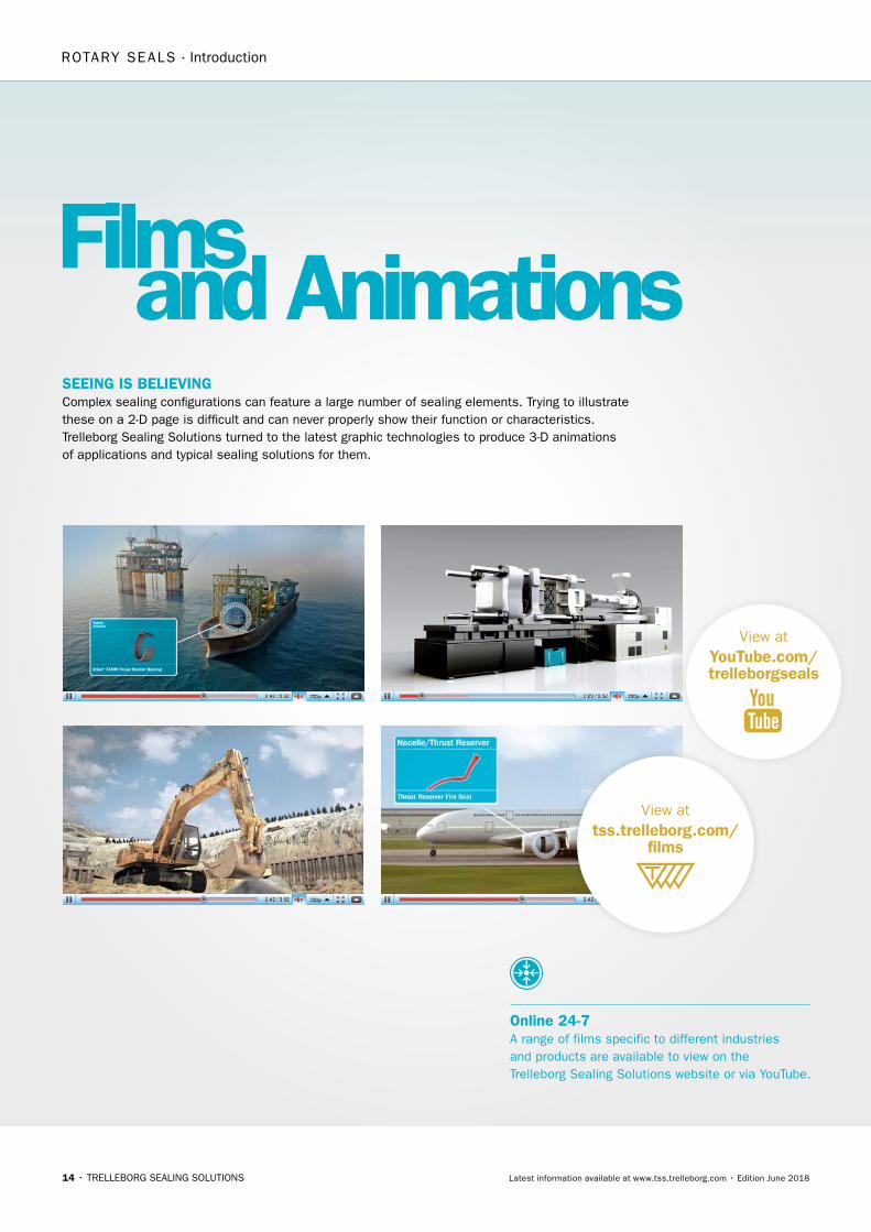
View atYouTube.com/trelleborgseals
View attss.trelleborg.com/
films
ROTARY SEALS · Introduction
Online 24-7A range of films specific to different industries and products are available to view on the Trelleborg Sealing Solutions website or via YouTube.
SEEING IS BELIEVING Complex sealing configurations can feature a large number of sealing elements. Trying to illustrate these on a 2-D page is difficult and can never properly show their function or characteristics. Trelleborg Sealing Solutions turned to the latest graphic technologies to produce 3-D animations of applications and typical sealing solutions for them.

TRELLEBORG SEALING SOLUTIONS • 15Latest information available at www.tss.trelleborg.com • Edition June 2018
Introduction

16 • TRELLEBORG SEALING SOLUTIONS Latest information available at www.tss.trelleborg.com • Edition June 2018
ROTARY SEALS · Introduction
Engineering Manufacturing AftermarketLogistics
Simplify Your BusinessService PLUSService PLUS aims at uniting various enhanced solutions across the entire value chain, simplifying the processes of engineering, logistics, manufacturing and aftermarket for the customer.
SPECIAL HANDLINGSpecial Handling bundles an assortment of individual packaging solutions together with additional services that optimize the mounting and handling of seals.
ENGINEERING SUPPORT SERVICESTrelleborg provides world-class expert support for your engineering needs, from extensive design & compound competence to leading edge product testing.
ADVANCED DELIVERY Our Advanced Delivery services simplify your stock replenishment process by managing your different vendors and stock levels – be it through a Kanban system or complete C-Part Management.
ASSEMBLYTrelleborg is willing and able to offer pre-assembled parts put together by specially trained staff, delivered directly to the customer.
QUICKSEALQuickSeal covers your short-notice needs for sealing solutions, whether you require a prototype, functional sample or a small batch rapidly.
DIGITAL TOOLSOnline resources and apps developed to make an engineer’s life easier.
www.tss.trelleborg.com
Discover our wide range of digital tools at

TRELLEBORG SEALING SOLUTIONS • 17Latest information available at www.tss.trelleborg.com • Edition June 2018
Introduction

18 • TRELLEBORG SEALING SOLUTIONS Latest information available at www.tss.trelleborg.com • Edition June 2018
+
–
+?
ONLINE TOOLS MAKE LIFE EASIERTrelleborg Sealing Solutions has developed a number of online tools that make the working life of an engineer specifying seals easier. All these industry-leading tools are available free-of-charge from the Trelleborg Sealing Solutions website at www.tss.trelleborg.com. To use these advanced services all you have to do is register on the Members Area.
There is also a continually increasing range of innovative engineering apps available for smartphones, both for iOS and Android devices. Just search for "Trelleborg" in the App Store or GooglePlay to find the tools to optimize your daily productivity.
Versatile CAD Service The CAD download facility provides thousands of drawings of a wide range of seals. It gives the option of 2- or 3-dimensional files in a range of formats to suit most commonly used CAD systems.
Materials Search and Chemical Compatibility Check These two programs allow you to find out the compatibility of sealing materials with hundreds of different media and help identify the most suitable material for your application.
DigitalServices
ROTARY SEALS · Introduction
Very good suitability
Good suitability
Limited suitability
Unsuitable
Insufficient information
TRELLEBORG SEALING SOLUTIONS • 19Latest information available at www.tss.trelleborg.com • Edition June 2018
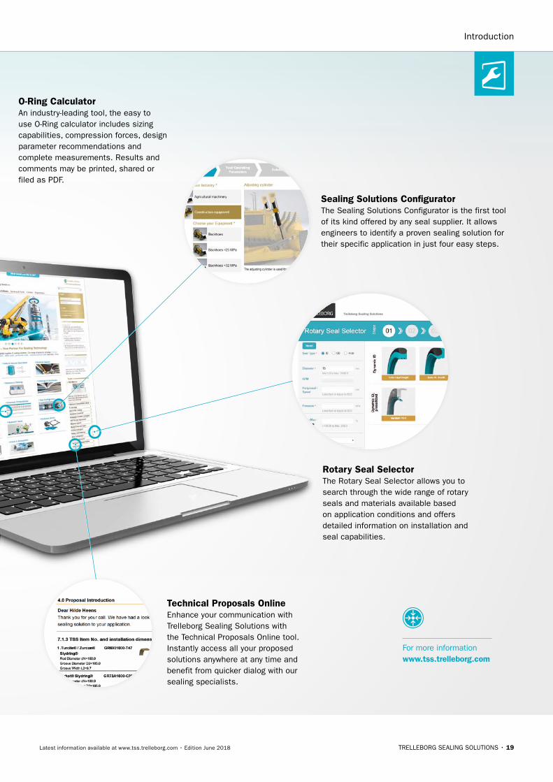
Sealing Solutions ConfiguratorThe Sealing Solutions Configurator is the first tool of its kind offered by any seal supplier. It allows engineers to identify a proven sealing solution for their specific application in just four easy steps.
O-Ring CalculatorAn industry-leading tool, the easy to use O-Ring calculator includes sizing capabilities, compression forces, design parameter recommendations and complete measurements. Results and comments may be printed, shared or filed as PDF.
Rotary Seal SelectorThe Rotary Seal Selector allows you to search through the wide range of rotary seals and materials available based on application conditions and offers detailed information on installation and seal capabilities.
Technical Proposals OnlineEnhance your communication with Trelleborg Sealing Solutions with the Technical Proposals Online tool. Instantly access all your proposed solutions anywhere at any time and benefit from quicker dialog with our sealing specialists.
Introduction
For more information www.tss.trelleborg.com

20 • TRELLEBORG SEALING SOLUTIONS Latest information available at www.tss.trelleborg.com • Edition June 2018
Mobile Appsand ServicesWe understand the needs of engineers on the go. Check out our latest mobile tools and apps, ranging from an O-Ring calculator to unit and hardness converters. Just search for "Trelleborg" in the App Store or Google Play to find the tools to optimize your daily productivity.
ISO Fits & TolerancesSimply enter the nominal
diameter and select the
tolerance classes for bore
and shaft to find the complete
ISO fits definition with all
relevant values including type
of fit, with handy graphs to
illustrate the classes by bore
and shaft.
ROTARY SEALS · Introduction
For more information www.tss.trelleborg.com
Technical Glossary This app provides definitions of more than 2,000 terms from the world of sealing technology and engineering.
Aerospace GrooveSelector This app covers two of the most important SAE aerospace groove standards for hydraulic systems, AS4716 Rev B and AS5857 Rev A, making it really easy to find the size of grooves and hardware needed.
Installation InstructionsVideos demonstrate thebest practice methods for installing seals, providing all relevant documentation within the interface, guiding you to a successful installation of Radial Oil Seals and Turcon® and Zurcon® rod and piston seals.
Unit & HardnessConverterIntuitive and very easy to use,simply select the dimension and enter the value for conversion. The app offers a wide range of engineering and scientific units for each dimension.
Available on theAPP STORE
MANY MORE APPS
available
Android App onGoogle Play

TRELLEBORG SEALING SOLUTIONS • 21Latest information available at www.tss.trelleborg.com • Edition June 2018
HydraulicCylinder CalculatorQuickly calculate areas and volumes in cylinders, extraction and retraction forces, time velocity and outflow by entering the requisite dimensions and parameters of the cylinder. In compliance with ISO 3320, ISO 3321 and ISO 4393.
Area and Volume CalculatorSpeeds up and simplifies cal-culating the area and volumes of more than 80 geometric shapes. The app supports both metric and imperial units and conveniently displays the formulas used. Fill your shape with solids or liquids, choosing from 1500 different materials, to calculate the weight.
Healthcare MaterialsView a quick and easy over-view of the compatibility of 34 materials with 35 chemical environments that are com-monly encountered in the healthcare and medical indus-tries. Select up to 20 materi-als and environments at once to produce a chart rating each material from "excellent" to "not recommended".
Sealing Materials SelectorEnter material specifications and required parameters, such as application temperature or hardness, to receive instant material proposals. The app features filters to limit searches based on chemical compatibility, institute approvals and product type and data sheets can be requested from within the interface.
in the groove Our in the groove magazine provides news, technical and product information on seals, as well as insights into the markets they are used in. The magazine is also available in print and as an interactive PDF.
Rotary SelectorBring the popular Rotary Seal Selector webtool with you! Quickly search through Trelleborg Sealing Solutions rotary seals and materials for the optimum product for your application conditions while on the move.
Introduction
O-Ring SelectorWhen a user enters installation specifications into the O-Ring Selector app, such as the bore or rod/shaft diameter, the app quickly calculates O-Ring and housing dimensions in both metric and inch.
ROTARY SEALS · Rotary Seals
22 • TRELLEBORG SEALING SOLUTIONS Latest information available at www.tss.trelleborg.com • Edition June 2018
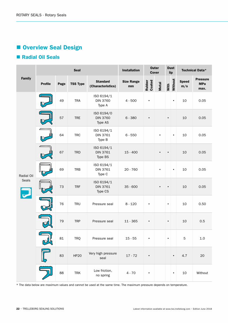
� Overview Seal Design
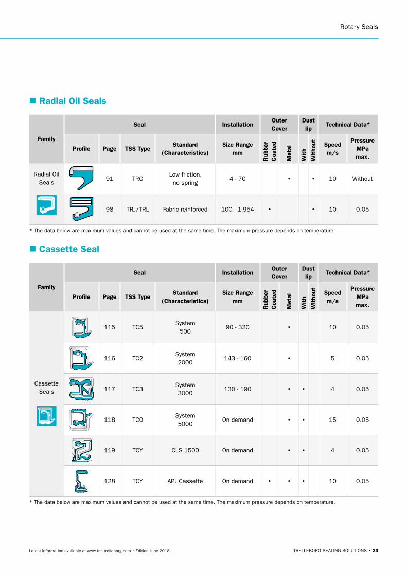
� Radial Oil Seals
Family
Seal InstallationOuter Cover
Dust lip
Technical Data*
Profile Page TSS TypeStandard
(Characteristics)Size Range
mm
Rub
ber
Coa
ted
Met
al
Wit
h
Wit
hout Speed
m/s
Pressure MPa max.
Radial Oil Seals
49 TRAISO 6194/1 DIN 3760
Type A4 - 500 • • 10 0.05
57 TREISO 6194/0 DIN 3760 Type AS
6 - 380 • • 10 0.05
64 TRCISO 6194/1 DIN 3761
Type B6 - 550 • • 10 0.05
67 TRDISO 6194/1 DIN 3761 Type BS
15 - 400 • • 10 0.05
69 TRBISO 6194/1 DIN 3761
Type C20 - 760 • • 10 0.05
73 TRFISO 6194/1 DIN 3761 Type CS
35 - 600 • • 10 0.05
76 TRU Pressure seal 8 - 120 • • 10 0.50
79 TRP Pressure seal 11 - 365 • • 10 0.5
81 TRQ Pressure seal 15 - 55 • • 5 1.0
83 HP20Very high pressure
seal 17 - 72 • • 4.7 20
88 TRKLow friction, no spring
4 - 70 • • 10 Without
* The data below are maximum values and cannot be used at the same time. The maximum pressure depends on temperature.
Rotary Seals
TRELLEBORG SEALING SOLUTIONS • 23Latest information available at www.tss.trelleborg.com • Edition June 2018
� Radial Oil Seals
Family
Seal InstallationOuter Cover
Dust lip
Technical Data*
Profile Page TSS TypeStandard
(Characteristics)Size Range
mm
Rub
ber
Coa
ted
Met
al
Wit
h
Wit
hout Speed
m/s
Pressure MPa max.
Radial Oil Seals
91 TRGLow friction, no spring
4 - 70 • • 10 Without
98 TRJ/TRL Fabric reinforced 100 - 1,954 • • 10 0.05
* The data below are maximum values and cannot be used at the same time. The maximum pressure depends on temperature.
Family
Seal InstallationOuter Cover
Dust lip
Technical Data*
Profile Page TSS TypeStandard
(Characteristics)Size Range
mm
Rub
ber
Coa
ted
Met
al
Wit
h
Wit
hout Speed
m/s
Pressure MPa max.
Cassette Seals
115 TC5System
50090 - 320 • 10 0.05
116 TC2System 2000
143 - 160 • 5 0.05
117 TC3System 3000
130 - 190 • • 4 0.05
118 TC0System 5000
On demand • • 15 0.05
119 TCY CLS 1500 On demand • • 4 0.05
128 TCY APJ Cassette On demand • • • 10 0.05
* The data below are maximum values and cannot be used at the same time. The maximum pressure depends on temperature.
� Cassette Seal
ROTARY SEALS · Rotary Seals
24 • TRELLEBORG SEALING SOLUTIONS Latest information available at www.tss.trelleborg.com • Edition June 2018
Family
Seal InstallationOuter Cover
Dust lip
Technical Data*
Profile Page TSS TypeStandard
(Characteristics)Size Range
mm
Rub
ber
Coa
ted
Met
al
Wit
h
Wit
hout Speed
m/s
Pressure MPa max.
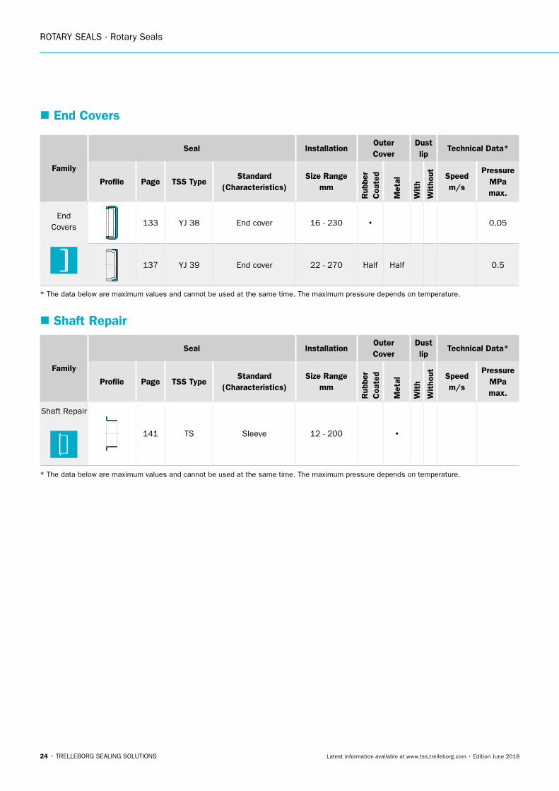
Shaft Repair
141 TS Sleeve 12 - 200 •
* The data below are maximum values and cannot be used at the same time. The maximum pressure depends on temperature.
Family
Seal InstallationOuter Cover
Dust lip
Technical Data*
Profile Page TSS TypeStandard
(Characteristics)Size Range
mm
Rub
ber
Coa
ted
Met
al
Wit
h
Wit
hout Speed
m/s
Pressure MPa max.
EndCovers 133 YJ 38 End cover 16 - 230 • 0.05
137 YJ 39 End cover 22 - 270 Half Half 0.5
* The data below are maximum values and cannot be used at the same time. The maximum pressure depends on temperature.
� End Covers
� Shaft Repair
Rotary Seals
TRELLEBORG SEALING SOLUTIONS • 25Latest information available at www.tss.trelleborg.com • Edition June 2018
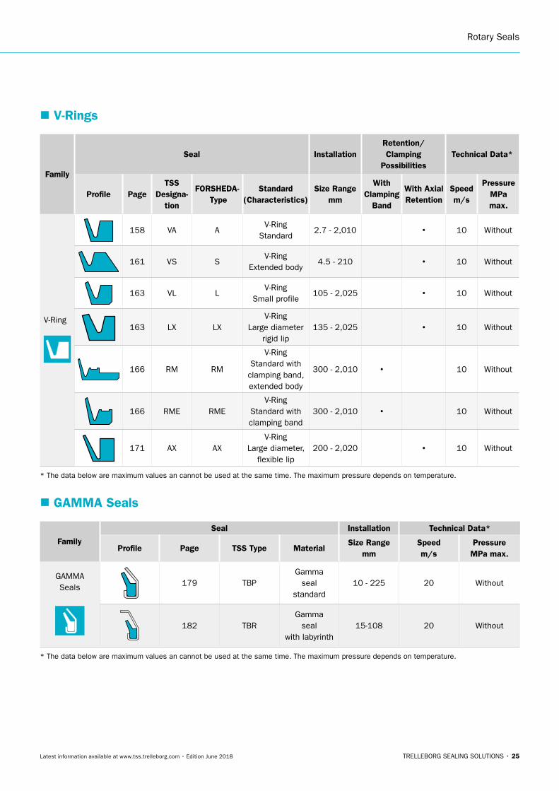
� V-Rings
Family
Seal InstallationRetention/ Clamping
PossibilitiesTechnical Data*
Profile PageTSS
Designa- tion
FORSHEDA- Type
Standard (Characteristics)
Size Range mm
With Clamping
Band
With Axial Retention
Speed m/s
Pressure MPa max.
V-Ring
158 VA AV-Ring
Standard2.7 - 2,010 • 10 Without
161 VS SV-Ring
Extended body4.5 - 210 • 10 Without
163 VL LV-Ring
Small profile105 - 2,025 • 10 Without
163 LX LXV-Ring
Large diameter rigid lip
135 - 2,025 • 10 Without
166 RM RM
V-Ring Standard with clamping band, extended body
300 - 2,010 • 10 Without
166 RME RMEV-Ring
Standard with clamping band
300 - 2,010 • 10 Without
171 AX AXV-Ring
Large diameter, flexible lip
200 - 2,020 • 10 Without
* The data below are maximum values an cannot be used at the same time. The maximum pressure depends on temperature.
� GAMMA Seals
Family
Seal Installation Technical Data*
Profile Page TSS Type MaterialSize Range
mmSpeed m/s
Pressure MPa max.
GAMMA Seals 179 TBP
Gamma seal
standard10 - 225 20 Without
182 TBRGamma
seal with labyrinth
15-108 20 Without
* The data below are maximum values an cannot be used at the same time. The maximum pressure depends on temperature.
ROTARY SEALS · Rotary Seals
26 • TRELLEBORG SEALING SOLUTIONS Latest information available at www.tss.trelleborg.com • Edition June 2018
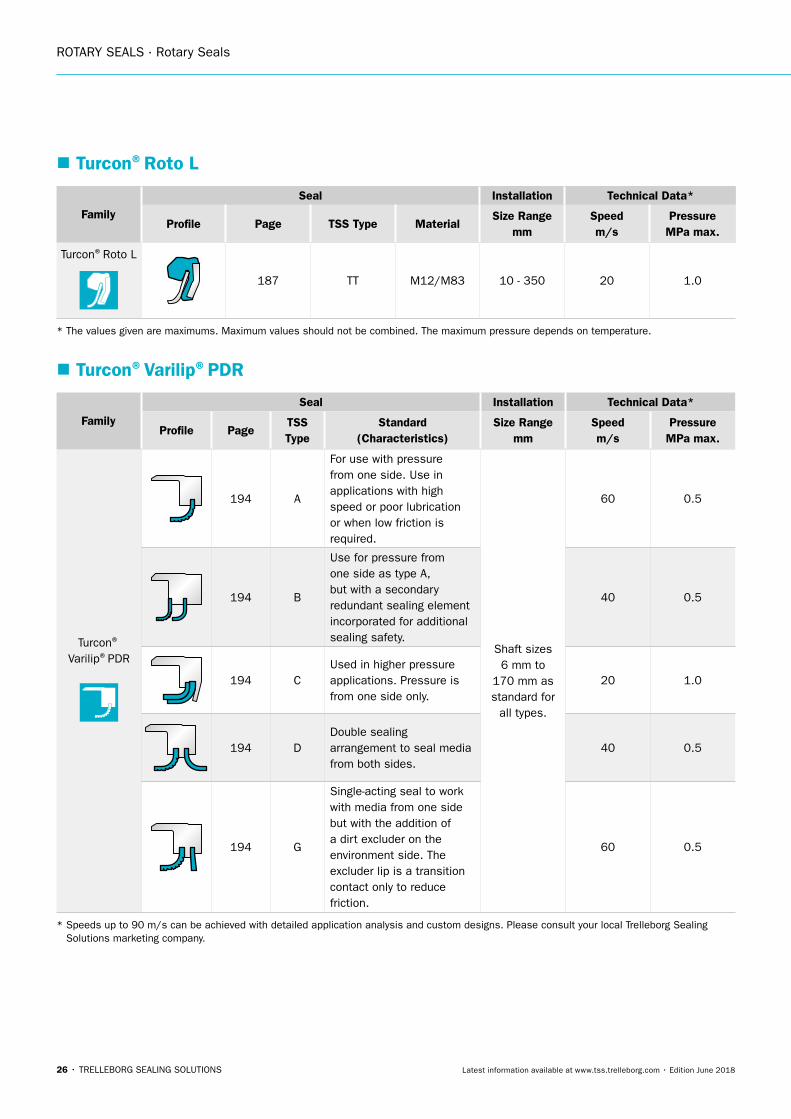
� Turcon®Roto L
Family
Seal Installation Technical Data*
Profile Page TSS Type MaterialSize Range
mmSpeed m/s
Pressure MPa max.
Turcon®Roto L
187 TT M12/M83 10 - 350 20 1.0
* The values given are maximums. Maximum values should not be combined. The maximum pressure depends on temperature.
� Turcon®Varilip®PDR
Family
Seal Installation Technical Data*
Profile PageTSS Type
Standard (Characteristics)
Size Range mm
Speed m/s
Pressure MPa max.
Turcon®
Varilip®PDR
194 A
For use with pressure from one side. Use in applications with high speed or poor lubrication or when low friction is required.
Shaft sizes 6 mm to
170 mm as standard for
all types.
60 0.5
194 B
Use for pressure from one side as type A, but with a secondary redundant sealing element incorporated for additional sealing safety.
40 0.5
194 CUsed in higher pressure applications. Pressure is from one side only.
20 1.0
194 DDouble sealing arrangement to seal media from both sides.
40 0.5
194 G
Single-acting seal to work with media from one side but with the addition of a dirt excluder on the environment side. The excluder lip is a transition contact only to reduce friction.
60 0.5
* Speeds up to 90 m/s can be achieved with detailed application analysis and custom designs. Please consult your local Trelleborg Sealing Solutions marketing company.
Rotary Seals
TRELLEBORG SEALING SOLUTIONS • 27Latest information available at www.tss.trelleborg.com • Edition June 2018
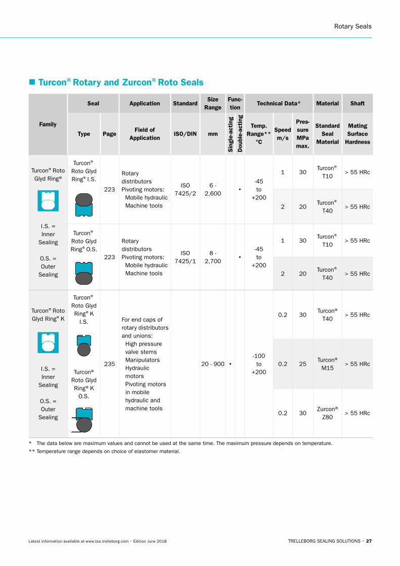
� Turcon®Rotary and Zurcon®Roto Seals
Family
Seal Application StandardSize
RangeFunc-tion
Technical Data* Material Shaft
Type PageField of
ApplicationISO/DIN mm
Sin
gle-
acti
ng
Dou
ble-
acti
ng
Temp. Range**
°C
Speedm/s
Pres- sureMPa max.
Standard Seal
Material
Mating Surface
Hardness
Turcon®Roto Glyd Ring®
I.S. = Inner
Sealing
O.S. = Outer
Sealing
Turcon® Roto Glyd Ring®I.S.
223
Rotary distributors Pivoting motors: Mobile hydraulic Machine tools
ISO 7425/2
6 - 2,600 •
-45 to
+200
1 30Turcon®
T10> 55 HRc
2 20Turcon®
T40> 55 HRc
Turcon® Roto Glyd Ring®O.S.
223
Rotary distributors Pivoting motors: Mobile hydraulic Machine tools
ISO 7425/1
8 - 2,700 •
-45 to
+200
1 30Turcon®
T10> 55 HRc
2 20Turcon®
T40> 55 HRc
Turcon®Roto Glyd Ring®K
I.S. = Inner
Sealing
O.S. = Outer
Sealing
Turcon®
Roto Glyd Ring®K
I.S.
Turcon®Roto Glyd Ring®K
O.S.
PL1
Srmax. 0.3
r1
D1
dN
d2
235
For end caps of rotary distributors and unions: High pressure valve stems
Manipulators Hydraulic motors
Pivoting motors in mobile hydraulic and machine tools
20 - 900 • -100 to
+200
0.2 30Turcon®
T40> 55 HRc
0.2 25Turcon®
M15> 55 HRc
0.2 30Zurcon®
Z80> 55 HRc
* The data below are maximum values and cannot be used at the same time. The maximum pressure depends on temperature.
** Temperature range depends on choice of elastomer material.
ROTARY SEALS · Rotary Seals
28 • TRELLEBORG SEALING SOLUTIONS Latest information available at www.tss.trelleborg.com • Edition June 2018
Family
Seal Application StandardSize
RangeFunc-tion
Technical Data* Material Shaft
Type PageField of
ApplicationISO/DIN mm
Sin
gle-
acti
ng
Dou
ble-
acti
ng
Temp. Range**
°C
Speedm/s
Pres- sureMPa max.
Standard Seal
Material
Mating Surface
Hardness
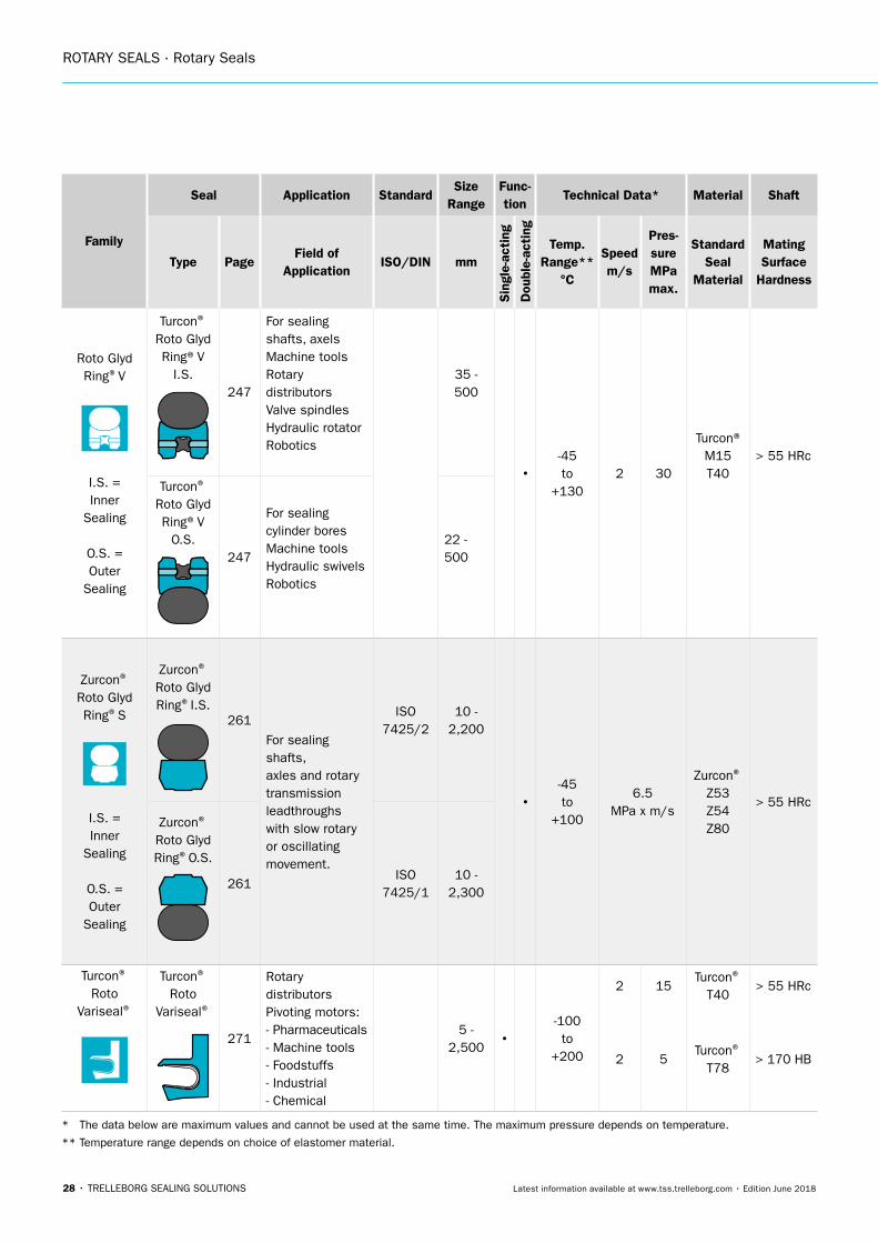
Roto Glyd Ring®V
I.S. = Inner
Sealing
O.S. = Outer
Sealing
Turcon®
Roto Glyd Ring®V
I.S.247
For sealingshafts, axelsMachine toolsRotary distributorsValve spindlesHydraulic rotatorRobotics
35 - 500
•-45 to
+1302 30
Turcon® M15 T40
> 55 HRc
Turcon®
Roto Glyd Ring®V
O.S.247
For sealingcylinder boresMachine toolsHydraulic swivelsRobotics
22 - 500
Zurcon® Roto Glyd Ring®S
I.S. = Inner
Sealing
O.S. = Outer
Sealing
Zurcon® Roto Glyd Ring®I.S.
261
For sealing shafts, axles and rotary transmission leadthroughs with slow rotary or oscillating movement.
ISO 7425/2
10 - 2,200
•-45 to
+100
6.5 MPa x m/s
Zurcon® Z53 Z54 Z80
> 55 HRc
Zurcon® Roto Glyd Ring®O.S.
261ISO
7425/110 -
2,300
Turcon® Roto
Variseal®
Turcon® Roto
Variseal®
271
Rotary distributors Pivoting motors: - Pharmaceuticals - Machine tools - Foodstuffs - Industrial - Chemical
5 - 2,500 •
-100 to
+200
2 15Turcon®
T40> 55 HRc
2 5Turcon®
T78> 170 HB
* The data below are maximum values and cannot be used at the same time. The maximum pressure depends on temperature.
** Temperature range depends on choice of elastomer material.
Rotary Seals
TRELLEBORG SEALING SOLUTIONS • 29Latest information available at www.tss.trelleborg.com • Edition June 2018
Family
Seal Application StandardSize
RangeFunc-tion
Technical Data* Material Shaft
Type PageField of
ApplicationISO/DIN mm
Sin
gle-
acti
ng
Dou
ble-
acti
ng
Temp. Range**
°C
Speedm/s
Pres- sureMPa max.
Standard Seal
Material
Mating Surface
Hardness
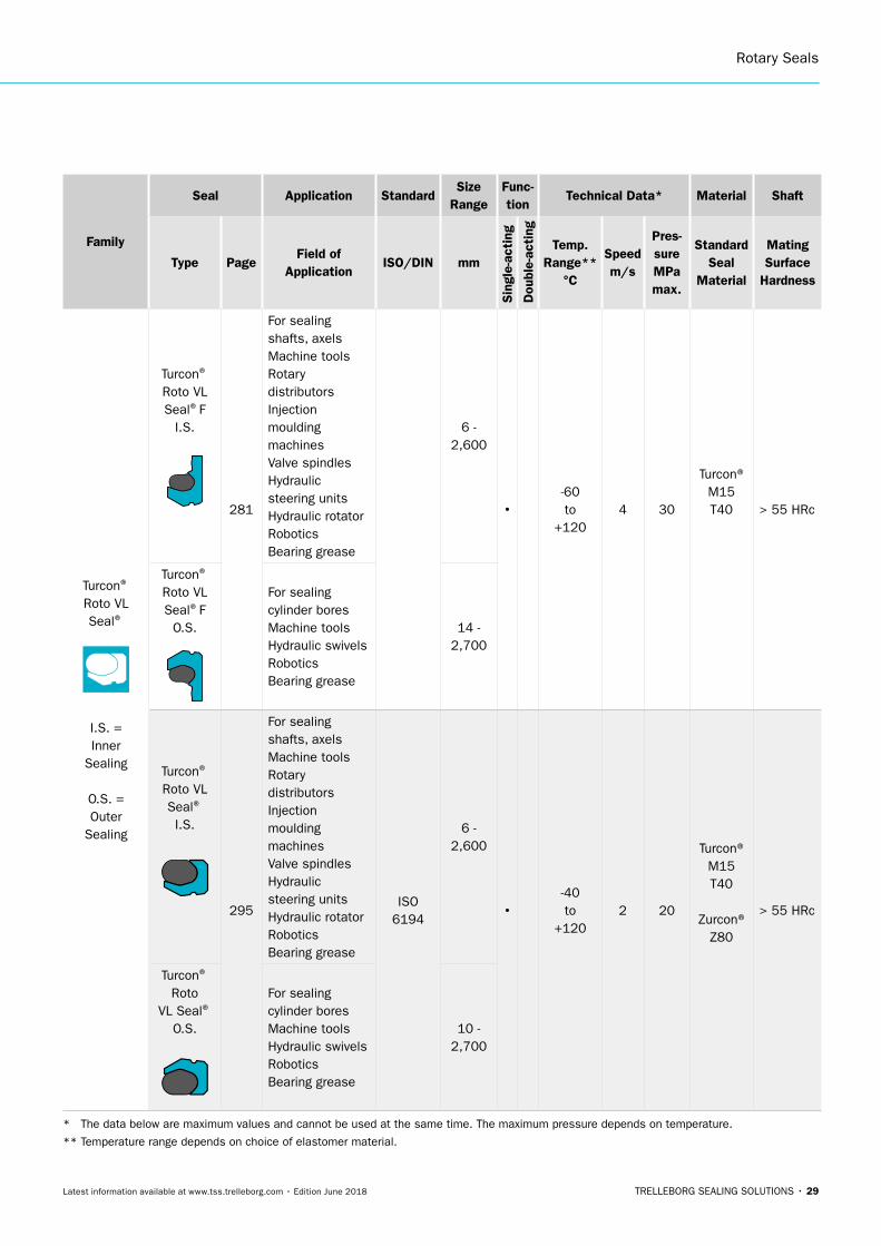
Turcon® Roto VL Seal®
I.S. = Inner
Sealing
O.S. = Outer
Sealing
Turcon®
Roto VL Seal®F
I.S.
281
For sealingshafts, axelsMachine toolsRotary distributorsInjection moulding machinesValve spindlesHydraulic steering unitsHydraulic rotatorRoboticsBearing grease
6 - 2,600
•-60 to
+1204 30
Turcon® M15 T40 > 55 HRc
Turcon®
Roto VL Seal®F
O.S.
For sealingcylinder boresMachine toolsHydraulic swivelsRoboticsBearing grease
14 - 2,700
Turcon®
Roto VL Seal®
I.S.
295
For sealingshafts, axelsMachine toolsRotary distributorsInjection moulding machinesValve spindlesHydraulic steering unitsHydraulic rotatorRoboticsBearing grease
ISO6194
6 - 2,600
•-40 to
+1202 20
Turcon® M15 T40
Zurcon®Z80
> 55 HRc
Turcon®
Roto VL Seal®
O.S.
For sealingcylinder boresMachine toolsHydraulic swivelsRoboticsBearing grease
10 - 2,700
* The data below are maximum values and cannot be used at the same time. The maximum pressure depends on temperature.
** Temperature range depends on choice of elastomer material.
ROTARY SEALS · Rotary Seals
30 • TRELLEBORG SEALING SOLUTIONS Latest information available at www.tss.trelleborg.com • Edition June 2018
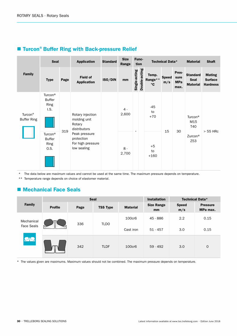
� Turcon®Buffer Ring with Back-pressure Relief
Family
Seal Application StandardSize
RangeFunc-tion
Technical Data* Material Shaft
Type PageField of
ApplicationISO/DIN mm
Sin
gle-
acti
ng
Dou
ble-
acti
ng
Temp. Range**
°C
Speedm/s
Pres- sureMPa max.
Standard Seal
Material
Mating Surface
Hardness
Turcon® Buffer Ring
Turcon®Buffer RingI.S.
319
Rotary injection molding unitRotary distributorsPeak pressure protectionFor high pressure low sealing
4 - 2,600
•
-45 to
+70
15 30
Turcon® M15 T40
Zurcon® Z53
> 55 HRcTurcon®Buffer RingO.S. 8 -
2,700
+5 to
+160
* The data below are maximum values and cannot be used at the same time. The maximum pressure depends on temperature.
** Temperature range depends on choice of elastomer material.
� Mechanical Face Seals
FamilySeal Installation Technical Data*
Profile Page TSS Type MaterialSize Range
mmSpeed m/s
Pressure MPa max.
Mechanical Face Seals
336 TLDO
100cr6 45 - 886 2.2 0.15
Cast iron 51 - 457 3.0 0.15
342 TLDF 100cr6 59 - 492 3.0 0
* The values given are maximums. Maximum values should not be combined. The maximum pressure depends on temperature.
TRELLEBORG SEALING SOLUTIONS • 31Latest information available at www.tss.trelleborg.com • Edition June 2018
Radial Oil Seal

ROTARY SEALS · Radial Oil Seal
32 • TRELLEBORG SEALING SOLUTIONS Latest information available at www.tss.trelleborg.com • Edition June 2018
Radial Oil Seal
TRELLEBORG SEALING SOLUTIONS • 33Latest information available at www.tss.trelleborg.com • Edition June 2018
� General Seal Description
GENERAL
Radial Oil Seals, also known as rotary shaft lip seals, are round sealing devices used to seal between two machine parts that rotate relative to each other. They are used to seal lubrication in and/or contamination out, or to separate dissimilar media.
SEAL DESIGN
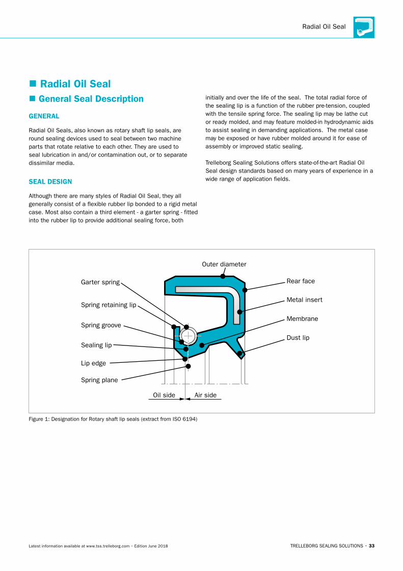
Although there are many styles of Radial Oil Seal, they all generally consist of a flexible rubber lip bonded to a rigid metal case. Most also contain a third element - a garter spring - fitted into the rubber lip to provide additional sealing force, both
initially and over the life of the seal. The total radial force of the sealing lip is a function of the rubber pre-tension, coupled with the tensile spring force. The sealing lip may be lathe cut or ready molded, and may feature molded-in hydrodynamic aids to assist sealing in demanding applications. The metal case may be exposed or have rubber molded around it for ease of assembly or improved static sealing.
Trelleborg Sealing Solutions offers state-of-the-art Radial Oil Seal design standards based on many years of experience in a wide range of application fields.
� Radial Oil Seal
Outer diameter
Rear face
Metal insert
Membrane
Dust lip
Spring retaining lip
Spring groove
Sealing lip
Spring plane
Oil side Air side
Garter spring
Lip edge
Figure 1: Designation for Rotary shaft lip seals (extract from ISO 6194)
ROTARY SEALS · Radial Oil Seal
34 • TRELLEBORG SEALING SOLUTIONS Latest information available at www.tss.trelleborg.com • Edition June 2018
METAL CASE
The metal case is normally made out of formed, cold-rolled steel sheet in accordance with DIN EN 10139. Another material, such as stainless steel or brass may be used, depending on application requirements. If the metal case is rubber-covered, the outside diameter may be either smooth or ribbed. In all cases, the seal outer diameter tolerance is in accordance with ISO 6194-1 and the bore tolerance is in accordance with ISO H8.
Table 1: Tolerance according ISO 6194-1
Nominal Outside Diameter Diametral Tolerance
d2 Metal Cased Rubber Covered
D2 < 50 +0.20 +0.30
+0.08 +0.15
50 < D2 < 80 +0.23 +0.35
+0.09 +0.20
80 < D2 < 120 +0.25 +0.35
+0.10 +0.20
120 < D2 < 180 +0.28 +0.45
+0.12 +0.25
180 < D2 < 300 +0.35 +0.45
+0.15 +0.25
300 < D2 < 530 +0.45 +0.55
+0.20 +0.30
Note: Ribbed O.D tolerances on request.
GARTER SPRING
FunctionWhen rubber is exposed to heat, pressure or chemical attack, it will gradually lose its original properties. The rubber is then said to have aged, causing the original radial force exerted by the sealing element to diminish. The function of the garter spring is to maintain the radial force during this period.
Experiments have shown that the radial force must vary with the size and type of seal. They have also clearly indicated the significance of maintaining the radial force within narrow limits during the service life of the seal. Extensive investigations in the laboratory have formed the basis for defining the radial force.
The garter spring is closely wound and carries an initial tension. The total force exerted by the spring consists of the force required to overcome the initial tension and the force due to the spring rate. The use of a garter spring with initial tension ensures that, as the sealing element wears, the total radial force from the initial tension will not change.
MaterialSpring steel is normally used. If resistance to corrosion is required, stainless steel can be substituted. Garter springs of bronze or similar materials are not recommended, since they tend to fatigue after long service life, or as a result of exposure to high temperatures. In special cases, the garter spring can be protected against damage by means of a thin rubber cover.
Radial Oil Seal
TRELLEBORG SEALING SOLUTIONS • 35Latest information available at www.tss.trelleborg.com • Edition June 2018
SURFACE FINISH, HARDNESS AND MACHINING
METHODS
The shaft design is vital for the sealing performance and ensures the maximum useful life of the seal (see Figure 4). As a basic principle, the hardness of the shaft should be higher as peripheral speeds increase. The Standard DIN 3760 specifies that the shaft must be hardened to at least 45 HRC.
As the peripheral speeds increase, the hardness must be increased, and at 10 m/s a hardness of 60 HRC is required. The choice of a suitable hardness is dependent not only on the peripheral speed but also on such factors as lubrication and the presence of abrasive particles. Poor lubrication and difficult environmental conditions require a higher shaft hardness. DIN 3760 specifies a surface roughness of Ra 0.2 - Ra 0.8 µm. Laboratory tests have however proved that the most suitable roughness is Rt = 2 μm (Ra = 0.3 μm). Rougher as well as smoother surfaces generate higher friction, resulting in increased temperature and wear. Trelleborg Sealing Solutions suggest a surface roughness of Ra 0.2 - 0.5 µm.
Measurements of friction and temperature have also shown that grinding of the shaft is the best method of machining. However, spiral grinding marks may cause a pumping effect. Therefore, plunge grinding should be used, during which even ratios between grinding wheel speed and work-piece should be avoided. Polishing of the shaft surface with a polishing cloth produces a surface which causes higher friction and increases heat generated when compared with plunge grinding. In certain cases it may be impossible to provide the necessary hardness, surface finish and corrosion resistance of the shaft. This problem can be solved by fitting a separate sleeve onto the shaft. If wear should occur, only the sleeve needs to be replaced (see information on Trelleborg Sealing Solutions “Shaft Repair Kit“).
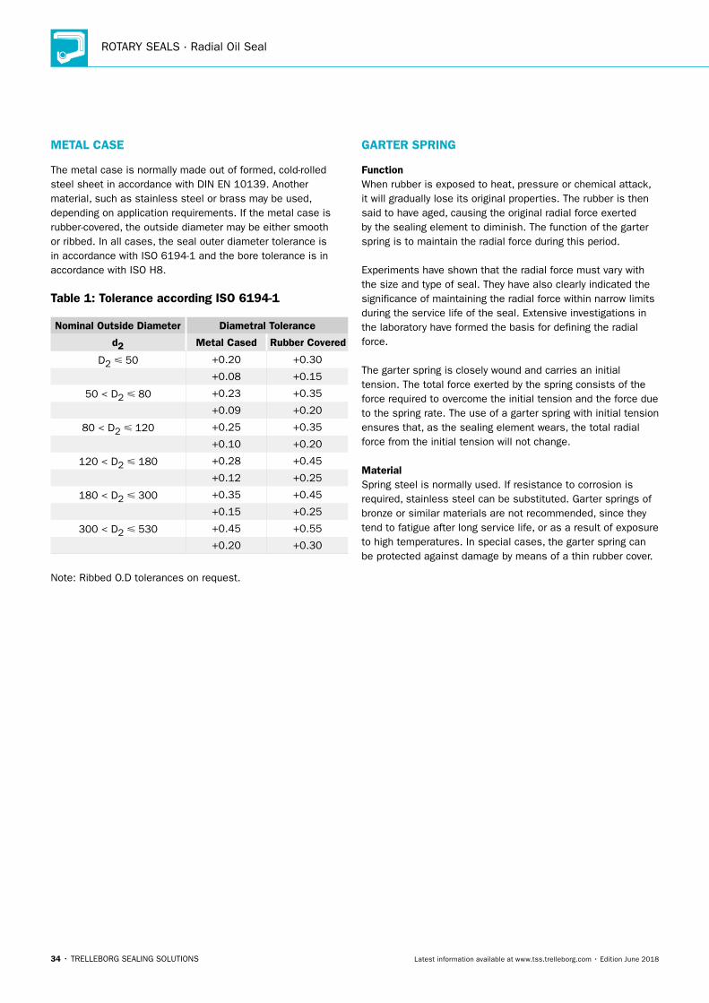
SHAFT RUN OUT
Shaft run out should as far as possible be avoided or kept within a minimum. At higher speeds there is a risk that the inertia of the sealing lip prevents it from following the shaft movement. The seal must be located next to the bearing and the bearing play should be maintained at the minimum value possible (see Figure 2).
0.4
0.3
0.2
0.1
0
Sha
ft r
un o
ut,
mm
Shaft speed, min-1
NBR-ACM-FKM
2000 4000 6000
Figure 2: Shaft run out
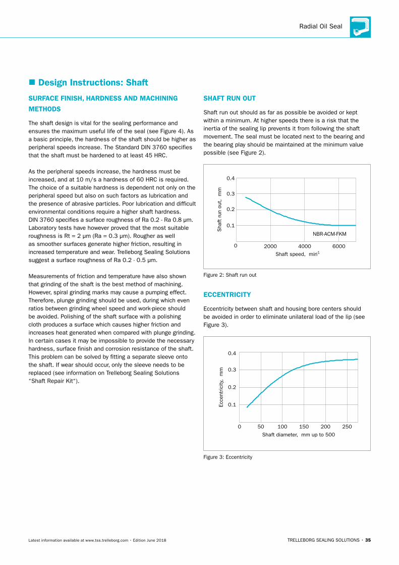
ECCENTRICITY
Eccentricity between shaft and housing bore centers should be avoided in order to eliminate unilateral load of the lip (see Figure 3).
0.4
0.3
0.2
0.1
0 50 100 150 200 250
Shaft diameter, mm up to 500
Ecce
ntric
ity, m
m
Figure 3: Eccentricity
� Design Instructions: Shaft
ROTARY SEALS · Radial Oil Seal
36 • TRELLEBORG SEALING SOLUTIONS Latest information available at www.tss.trelleborg.com • Edition June 2018
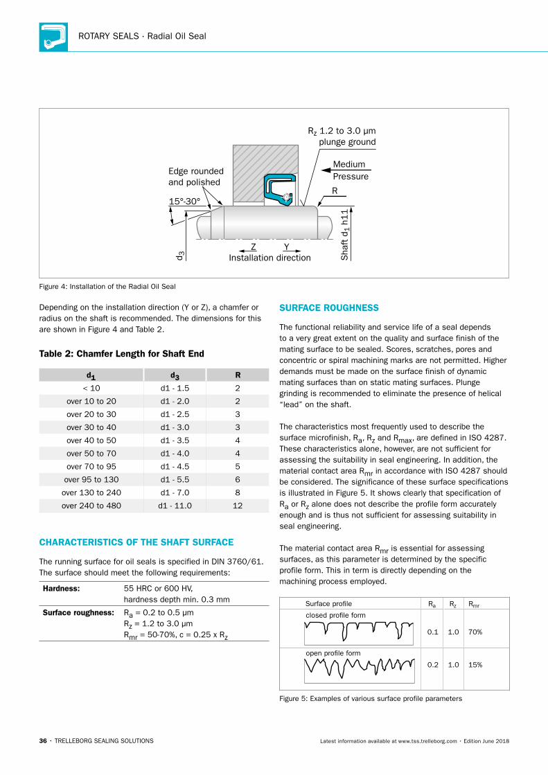
Depending on the installation direction (Y or Z), a chamfer or radius on the shaft is recommended. The dimensions for this are shown in Figure 4 and Table 2.
Table 2: Chamfer Length for Shaft End
d1 d3 R
< 10 d1 - 1.5 2
over 10 to 20 d1 - 2.0 2
over 20 to 30 d1 - 2.5 3
over 30 to 40 d1 - 3.0 3
over 40 to 50 d1 - 3.5 4
over 50 to 70 d1 - 4.0 4
over 70 to 95 d1 - 4.5 5
over 95 to 130 d1 - 5.5 6
over 130 to 240 d1 - 7.0 8
over 240 to 480 d1 - 11.0 12
CHARACTERISTICS OF THE SHAFT SURFACE
The running surface for oil seals is specified in DIN 3760/61. The surface should meet the following requirements:
Hardness: 55 HRC or 600 HV, hardness depth min. 0.3 mm
Surface roughness: Ra = 0.2 to 0.5 μmRz = 1.2 to 3.0 μmRmr = 50-70%, c = 0.25 x Rz
SURFACE ROUGHNESS
The functional reliability and service life of a seal depends to a very great extent on the quality and surface finish of the mating surface to be sealed. Scores, scratches, pores and concentric or spiral machining marks are not permitted. Higher demands must be made on the surface finish of dynamic mating surfaces than on static mating surfaces. Plunge grinding is recommended to eliminate the presence of helical “lead” on the shaft.
The characteristics most frequently used to describe the surface microfinish, Ra, Rz and Rmax, are defined in ISO 4287. These characteristics alone, however, are not sufficient for assessing the suitability in seal engineering. In addition, the material contact area Rmr in accordance with ISO 4287 should be considered. The significance of these surface specifications is illustrated in Figure 5. It shows clearly that specification of Ra or Rz alone does not describe the profile form accurately enough and is thus not sufficient for assessing suitability in seal engineering.
The material contact area Rmr is essential for assessing surfaces, as this parameter is determined by the specific profile form. This in term is directly depending on the machining process employed.
Surface pro�le
closed pro�le form
open pro�le form
RzRa
0.1 1.0 70%
Rmr
0.2 1.0 15%
Figure 5: Examples of various surface profile parameters
Edge roundedand polished
Rz 1.2 to 3.0 μmplunge ground
Installation direction
MediumPressure
d 3 Sha
ft d
1 h
11
R15°-30°
YZ
Figure 4: Installation of the Radial Oil Seal
Radial Oil Seal
TRELLEBORG SEALING SOLUTIONS • 37Latest information available at www.tss.trelleborg.com • Edition June 2018
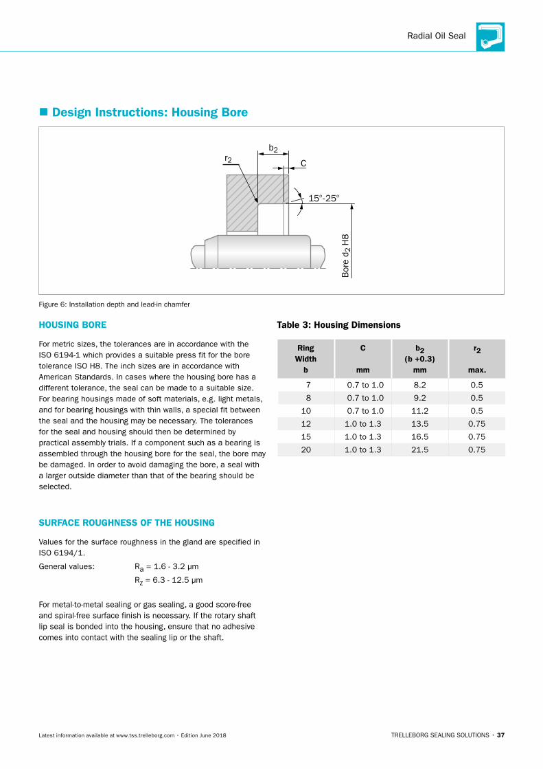
HOUSING BORE
For metric sizes, the tolerances are in accordance with the ISO 6194-1 which provides a suitable press fit for the bore tolerance ISO H8. The inch sizes are in accordance with American Standards. In cases where the housing bore has a different tolerance, the seal can be made to a suitable size. For bearing housings made of soft materials, e.g. light metals, and for bearing housings with thin walls, a special fit between the seal and the housing may be necessary. The tolerances for the seal and housing should then be determined by practical assembly trials. If a component such as a bearing is assembled through the housing bore for the seal, the bore may be damaged. In order to avoid damaging the bore, a seal with a larger outside diameter than that of the bearing should be selected.
SURFACE ROUGHNESS OF THE HOUSING
Values for the surface roughness in the gland are specified in ISO 6194/1.
General values: Ra = 1.6 - 3.2 μm
Rz = 6.3 - 12.5 μm
For metal-to-metal sealing or gas sealing, a good score-free and spiral-free surface finish is necessary. If the rotary shaft lip seal is bonded into the housing, ensure that no adhesive comes into contact with the sealing lip or the shaft.
Table 3: Housing Dimensions
Ring Width
b
C
mm
b2 (b+0.3)
mm
r2
max.
7 0.7 to 1.0 8.2 0.5
8 0.7 to 1.0 9.2 0.5
10 0.7 to 1.0 11.2 0.5
12 1.0 to 1.3 13.5 0.75
15 1.0 to 1.3 16.5 0.75
20 1.0 to 1.3 21.5 0.75
� Design Instructions: Housing Bore
Bor
e d 2
H8
b2r2
15°-25°
C
Figure 6: Installation depth and lead-in chamfer
ROTARY SEALS · Radial Oil Seal
38 • TRELLEBORG SEALING SOLUTIONS Latest information available at www.tss.trelleborg.com • Edition June 2018
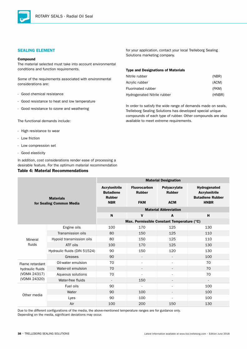
Table 4: Material Recommendations
Materials for Sealing Common Media
Material Designation
Acrylonitrile Butadiene
Rubber NBR
Fluorocarbon Rubber
FKM
Polyacrylate Rubber
ACM
Hydrogenated Acrylonitrile
Butadiene Rubber HNBR
Material Abbreviation
N V A H
Max. Permissible Constant Temperature (°C)
Mineral fluids
Engine oils 100 170 125 130
Transmission oils 80 150 125 110
Hypoid transmission oils 80 150 125 110
ATF oils 100 170 125 130
Hydraulic fluids (DIN 51524) 90 150 120 130
Greases 90 - - 100
Flame retardant hydraulic fluids (VDMA 24317) (VDMA 24320)
Oil-water emulsion 70 - - 70
Water-oil emulsion 70 - - 70
Aqueous solutions 70 - - 70
Water-free fluids - 150 - -
Other media
Fuel oils 90 - - 100
Water 90 100 - 100
Lyes 90 100 - 100
Air 100 200 150 130
Due to the different configurations of the media, the above-mentioned temperature ranges are for guidance only. Depending on the media, significant deviations may occur.
SEALING ELEMENT
CompoundThe material selected must take into account environmental conditions and function requirements.
Some of the requirements associated with environmental considerations are:
- Good chemical resistance
- Good resistance to heat and low temperature
- Good resistance to ozone and weathering
The functional demands include:
- High resistance to wear
- Low friction
- Low compression set
- Good elasticity
In addition, cost considerations render ease of processing a desirable feature. For the optimum material recommendation
for your application, contact your local Trelleborg Sealing Solutions marketing company.
Type and Designations of Materials
Nitrile rubber (NBR)
Acrylic rubber (ACM)
Fluorinated rubber (FKM)
Hydrogenated Nitrile rubber (HNBR)
In order to satisfy the wide range of demands made on seals, Trelleborg Sealing Solutions has developed special unique compounds of each type of rubber. Other compounds are also available to meet extreme requirements.
Radial Oil Seal
TRELLEBORG SEALING SOLUTIONS • 39Latest information available at www.tss.trelleborg.com • Edition June 2018
� Description of Rubber Materials
NITRILE RUBBER (NBR)
Advantages: - Good oil resistance
- Good heat resistance up to +100 °C in oil
- High tensile strength (special compounds over 20 MPa)
- High elongation at break
- Low swelling in water
Limitations: - Poor weather and ozone resistance
- Poor resistance against polar fluids (ester, ether, ketones and aniline)
- Poor resistance against chlorinated hydrocarbons (carbon tetrachloride, trichlorethylene)
- Poor resistance against aromatic fluids (e.g. benzene, toluene)
Fluids, mineral oils and, above all, high-alloyed mineral oils (hypoid oils) containing larger quantities of aromatic hydrocarbons have a high swelling effect on NBR compounds. The swelling behavior can be improved by increasing the acrylonitrile content.
However an inferior cold flexibility and resistance to compression set must be accepted. The additives in high- alloyed oils can in certain cases cause an additional interaction between the elastomer and the additive, thus influencing the elasticity.
HYDROGENATED NITRILE RUBBER (HNBR)
Advantages: - Good oil resistance, also in hypoid oils
- Good heat resistance, up to +150 °C
- Good mechanical properties
- Good weather and ozone resistance
Limitations: - Poor resistance against polar fluids (esters, ethers, ketones
and aniline)
- Poor resistance against chlorinated hydrocarbons (carbon tetrachloride, trichlorethylene)
- Poor resistance against aromatic fluids (benzene, toluene)
POLYACRYLIC RUBBER (ACM)
Advantages: - Good resistance against oils and fuels (better than Nitrile
rubber)
- Heat resistance about +50 °C better than for Nitrile rubber, +150 °C in oil and +125 °C in air
- Good weather and ozone resistance
Limitations: - Not usable in contact with water and water solutions, even
smaller quantities of water in oil
- Limited cold flexibility to about -20 °C, somewhat poorer than normal NBR
- Limited tensile strength and tear resistance, especially above +100 °C
- Poor wear resistance (considerably inferior compared to NBR)
- Poor resistance against polar and aromatic fluids and chlorinated hydrocarbons
FLUORINATED RUBBER (FKM)
Advantages: - The resistance against oils and fuels is better than for any
other rubber type
- The only highly elastic rubber material, which is resistant to aromatic and chlorinated hydrocarbons
- Excellent heat resistance, up to +200 °C
- Excellent weather and ozone resistance
- Excellent acid resistance (only inorganic acids, not suitable for organic acids e.g. acetic acid)
Limitations: - Limited cold flexibility, to approximately +20 °C to -25 °C
- Limited tensile and tear strength, especially above +100 °C
- High compression set in hot water
- Poor resistance to polar solvents
ROTARY SEALS · Radial Oil Seal
40 • TRELLEBORG SEALING SOLUTIONS Latest information available at www.tss.trelleborg.com • Edition June 2018
FLUOROSILICONE (FVMQ)
Advantages: - Very low temperature flexibility down to -60 °C
- Excellent heat resistance, up to +230 °C
- Good compatibility with most mineral oils
Advantages: - Expensive material
- Not suitable with polar fluids
FDA-COMPOUNDS
Trelleborg Sealing Solutions has engineered a set of compounds suitable to be used in rotary sealing applications like gearboxes, mixers and other equipment requiring a separation between lubricants and food or any external chemicals.
The elastomeric lip is energized by a spring and can be designed like any Radial Oil Seal in order to effectively work under pressure, with shaft eccentricities and vibrations, with axial play.
Available types of compounds are updated according to state of the art regulations like the FDA. Most available Radial Oil Seals are molded from EPDM and FKM polymers, bonded to stainless steel metal inserts and energized with special INOX springs. The engineering of these items is usually made according to customer specifications.
Radial Oil Seal
TRELLEBORG SEALING SOLUTIONS • 41Latest information available at www.tss.trelleborg.com • Edition June 2018
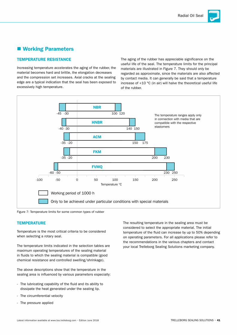
The temperature ranges apply onlyin connection with media that arecompatible with the respectiveelastomers
Working period of 1000 h
Only to be achieved under particular conditions with special materials
Temperature °C1501000 50-50-100
FVMQ250230-50-60
NBR
HNBR
ACM
FKM230200-20-35
175150-20-35
150140-30-40
120100-30-45
250200
Figure 7: Temperature limits for some common types of rubber
TEMPERATURE RESISTANCE
Increasing temperature accelerates the aging of the rubber, the material becomes hard and brittle, the elongation decreases and the compression set increases. Axial cracks at the sealing edge are a typical indication that the seal has been exposed to excessively high temperature.
The aging of the rubber has appreciable significance on the useful life of the seal. The temperature limits for the principal materials are illustrated in Figure 7. They should only be regarded as approximate, since the materials are also affected by contact media. It can generally be said that a temperature increase of +10 °C (in air) will halve the theoretical useful life of the rubber.
TEMPERATURE
Temperature is the most critical criteria to be considered when selecting a rotary seal.
The temperature limits indicated in the selection tables are maximum operating temperatures of the sealing material in fluids to which the sealing material is compatible (good chemical resistance and controlled swelling/shrinkage).
The above descriptions show that the temperature in the sealing area is influenced by various parameters especially:
- The lubricating capability of the fluid and its ability to dissipate the heat generated under the sealing lip.
- The circumferential velocity
- The pressure applied
The resulting temperature in the sealing area must be considered to select the appropriate material. The initial temperature of the fluid can increase by up to 50% depending on operating parameters. For all applications please refer to the recommendations in the various chapters and contact your local Trelleborg Sealing Solutions marketing company.
� Working Parameters
ROTARY SEALS · Radial Oil Seal
42 • TRELLEBORG SEALING SOLUTIONS Latest information available at www.tss.trelleborg.com • Edition June 2018
MEDIA
The media to be sealed influences heavily the choice of the seal and material type. Mainly liquid media need to be sealed in rotary applications. Pasty media generally restrict the use of rotary seals, especially in terms of circumferential velocity. Gaseous media require specially adapted seal designs.
Liquid media:Most of the applications relate to lubricating fluids but also hydraulic fluids based on mineral oils acc. DIN 51524 or ISO 6743 or fire resistant hydraulic fluids as well as environmentally friendly hydraulic fluids. In specific applications involving aggressive media with low lubricating capabilities must be sealed. Sealing of other fluids such as water or FDA compliant fluids require in many cases a special sealing solution and will not be covered in detail in this catalog. For specific requirements please contact your local Trelleborg Sealing Solutions marketing company. The media is the first criteria to be considered for the selection of the sealing material type. It will also influence the seal family and the profile.
The evaluation of the compatibility of the seal material with the media to be sealed is based on the analysis of the values of tensile strength, elongation, volume change and hardness change resulting from an immersion test of testing slabs. Please contact your local Trelleborg Sealing Solutions marketing company to select the optimum material for your application.
Mineral oils:Mainly used in transmissions, elastomer materials have good compatibility with mineral oils within the recommended temperature range. Some mineral oils e.g. hypoid transmission oils contain special additives which produce more demanding operating conditions e.g. temperature range and/or high pressure. For these fields testing is recommended.
Synthetic oils:For improvement of the viscosity, high temperature and/or service life, new oils with specific additives have been launched as partial or full synthetic oils. Elastomer sealing materials give the same good compatibility to synthetic mineral oils as they do to mineral oils. However, compatibility needs to be checked.
Grease:Often used for roller and plain bearings, this media requires a specially adapted sealing solution. To reduce the risk of tilting and to allow the sealing lip to open under increasing pressure, the seal is installed in the reverse direction. Another important parameter to be considered is the maximum circumferential velocity. The maximum speed must be reduced to 50% of the permitted speed in oil, due to the poor heat exchange the grease can provide.Above this limit the change from grease to oil or installation of seal with PTFE-based lip (Turcon®) should be considered.
Poor lubricating media:For those media an initial lubrication of the seal is required to avoid dry running. In such applications we recommend the radial oil seal with dust lip. The area between the lips will be used as a lubricant reservoir. Two seals in tandem Radial oil seal/Radial oil seal or Radial oil seal/GAMMA seal will provide the same result.
Aggressive media:Generally aggressive media (e.g. solvents) have poor lubricating properties and therefore we recommend Turcon®Varilip®or PDR seals. Turcon®and other PTFE materials solve the problem of chemical resistance and the metal cage can be produced out of various Stainless Steel materials.
Radial Oil Seal
TRELLEBORG SEALING SOLUTIONS • 43Latest information available at www.tss.trelleborg.com • Edition June 2018
Table 5: Recommendations for the use of standard elastomer materials and accordance with ISO VG 32 to 68 and VDMA Directive 24569
Oil Temperature < 60 °C < 80 °C < 100 °C < 120 °C
Oil Type / ISO VG 32 - 68 32 - 68 32 - 68 32 - 68
HETG
( Rapeseed )
NBR HNBR FKM
NBR HNBR FKM
- - -
- - -
HEESNBR*
HNBR* FKM*
NBR* HNBR* FKM
- -
FKM
- -
FKM
HEPG
( PAG )
NBR* HNBR* FKM*
NBR HNBR FKM**
- HNBR FKM**
- HNBR FKM**
HEPR ( PAO ) not yet specified not yet specified not yet specified not yet specified
* For dynamic application, specific test required ** Preferred peroxide cured FKM
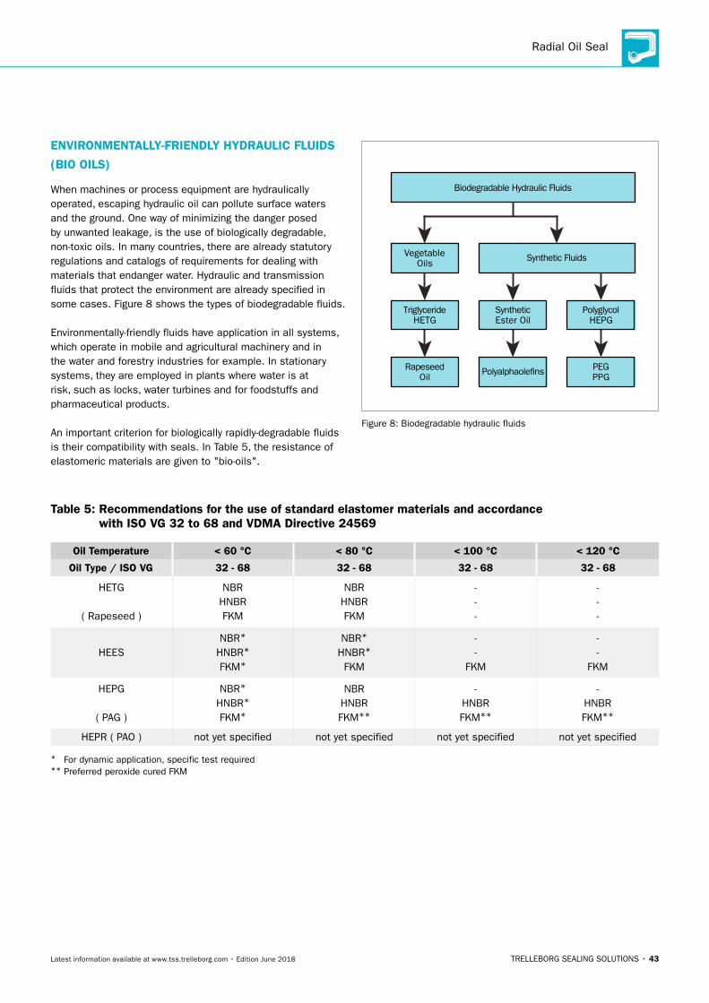
ENVIRONMENTALLY-FRIENDLY HYDRAULIC FLUIDS
(BIO OILS)
When machines or process equipment are hydraulically operated, escaping hydraulic oil can pollute surface waters and the ground. One way of minimizing the danger posed by unwanted leakage, is the use of biologically degradable, non-toxic oils. In many countries, there are already statutory regulations and catalogs of requirements for dealing with materials that endanger water. Hydraulic and transmission fluids that protect the environment are already specified in some cases. Figure 8 shows the types of biodegradable fluids.
Environmentally-friendly fluids have application in all systems, which operate in mobile and agricultural machinery and in the water and forestry industries for example. In stationary systems, they are employed in plants where water is at risk, such as locks, water turbines and for foodstuffs and pharmaceutical products.
An important criterion for biologically rapidly-degradable fluids is their compatibility with seals. In Table 5, the resistance of elastomeric materials are given to "bio-oils".
Polyalphaole�ns
Biodegradable Hydraulic Fluids
Rapeseed Oil
PEG PPG
SyntheticEster Oil
TriglycerideHETG
PolyglycolHEPG
VegetableOils
Synthetic Fluids
Figure 8: Biodegradable hydraulic fluids
ROTARY SEALS · Radial Oil Seal
44 • TRELLEBORG SEALING SOLUTIONS Latest information available at www.tss.trelleborg.com • Edition June 2018
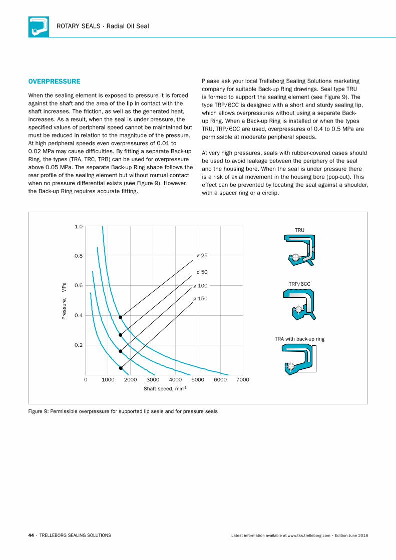
OVERPRESSURE
When the sealing element is exposed to pressure it is forced against the shaft and the area of the lip in contact with the shaft increases. The friction, as well as the generated heat, increases. As a result, when the seal is under pressure, the specified values of peripheral speed cannot be maintained but must be reduced in relation to the magnitude of the pressure. At high peripheral speeds even overpressures of 0.01 to 0.02 MPa may cause difficulties. By fitting a separate Back-up Ring, the types (TRA, TRC, TRB) can be used for overpressure above 0.05 MPa. The separate Back-up Ring shape follows the rear profile of the sealing element but without mutual contact when no pressure differential exists (see Figure 9). However, the Back-up Ring requires accurate fitting.
Please ask your local Trelleborg Sealing Solutions marketing company for suitable Back-up Ring drawings. Seal type TRU is formed to support the sealing element (see Figure 9). The type TRP/6CC is designed with a short and sturdy sealing lip, which allows overpressures without using a separate Back-up Ring. When a Back-up Ring is installed or when the types TRU, TRP/6CC are used, overpressures of 0.4 to 0.5 MPa are permissible at moderate peripheral speeds.
At very high pressures, seals with rubber-covered cases should be used to avoid leakage between the periphery of the seal and the housing bore. When the seal is under pressure there is a risk of axial movement in the housing bore (pop-out). This effect can be prevented by locating the seal against a shoulder, with a spacer ring or a circlip.
1.0
0.8
0.6
0.4
0.2
0
Pres
sure
, M
Pa
Shaft speed, min
ø 25
ø 50
ø 100
ø 150
1000 60005000400030002000 7000-1
TRP/6CC
TRU
TRA with back-up ring
Figure 9: Permissible overpressure for supported lip seals and for pressure seals
Radial Oil Seal
TRELLEBORG SEALING SOLUTIONS • 45Latest information available at www.tss.trelleborg.com • Edition June 2018
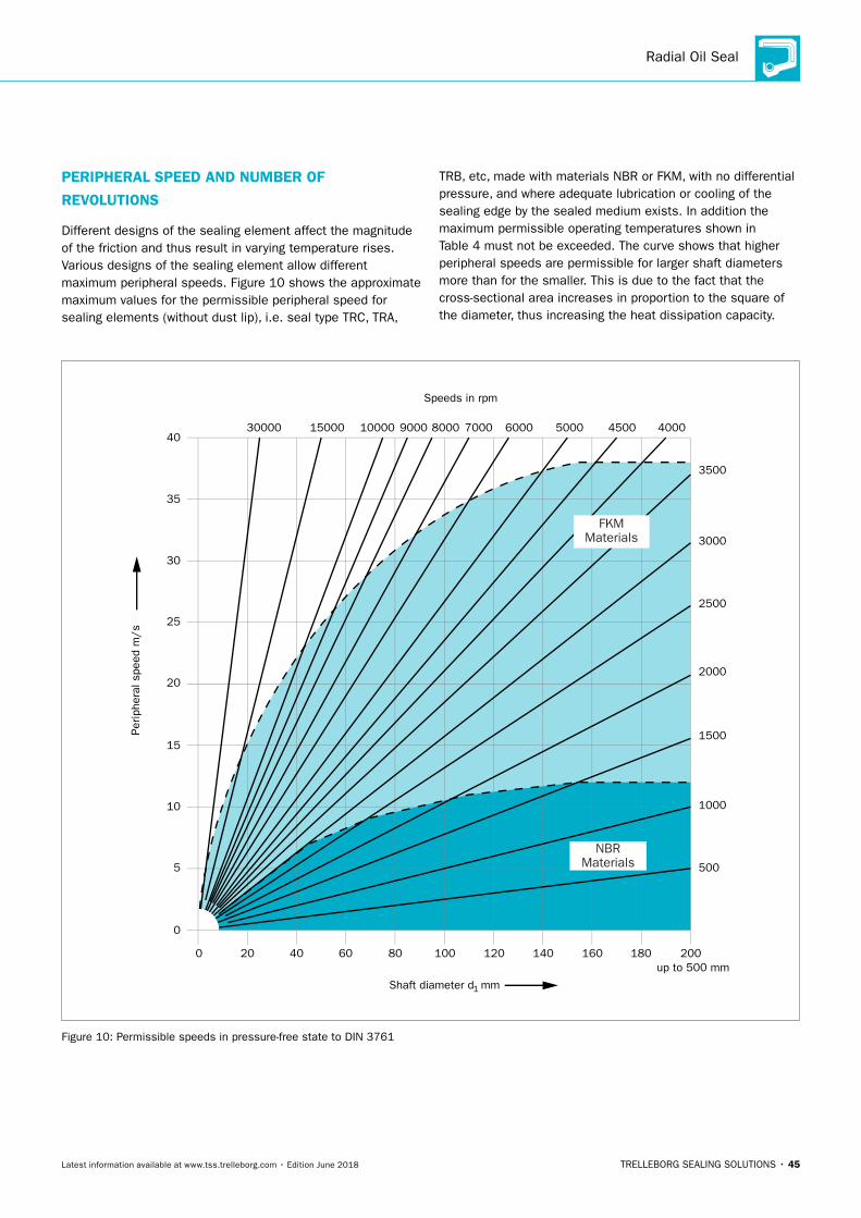
PERIPHERAL SPEED AND NUMBER OF
REVOLUTIONS
Different designs of the sealing element affect the magnitude of the friction and thus result in varying temperature rises. Various designs of the sealing element allow different maximum peripheral speeds. Figure 10 shows the approximate maximum values for the permissible peripheral speed for sealing elements (without dust lip), i.e. seal type TRC, TRA,
TRB, etc, made with materials NBR or FKM, with no differential pressure, and where adequate lubrication or cooling of the sealing edge by the sealed medium exists. In addition the maximum permissible operating temperatures shown in Table 4 must not be exceeded. The curve shows that higher peripheral speeds are permissible for larger shaft diameters more than for the smaller. This is due to the fact that the cross-sectional area increases in proportion to the square of the diameter, thus increasing the heat dissipation capacity.
NBRMaterials
FKMMaterials
Speeds in rpm
3500
2500
2000
1500
1000
500
up to 500 mm
Perip
hera
l spe
ed m
/s
40
35
30
25
20
15
10
5
0
Shaft diameter d mm1
3000
0 10080604020 160140120 200180
4000450050006000700080009000100001500030000
Figure 10: Permissible speeds in pressure-free state to DIN 3761
ROTARY SEALS · Radial Oil Seal
46 • TRELLEBORG SEALING SOLUTIONS Latest information available at www.tss.trelleborg.com • Edition June 2018
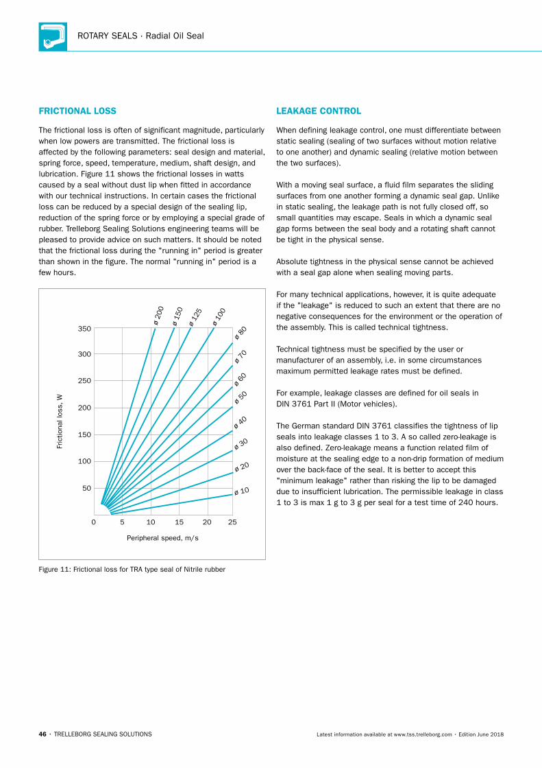
FRICTIONAL LOSS
The frictional loss is often of significant magnitude, particularly when low powers are transmitted. The frictional loss is affected by the following parameters: seal design and material, spring force, speed, temperature, medium, shaft design, and lubrication. Figure 11 shows the frictional losses in watts caused by a seal without dust lip when fitted in accordance with our technical instructions. In certain cases the frictional loss can be reduced by a special design of the sealing lip, reduction of the spring force or by employing a special grade of rubber. Trelleborg Sealing Solutions engineering teams will be pleased to provide advice on such matters. It should be noted that the frictional loss during the "running in" period is greater than shown in the figure. The normal "running in" period is a few hours.
Fric
tiona
l los
s, W
Peripheral speed, m/s
350
300
250
200
150
100
50
1510
ø 20
0
ø 15
0ø
125
ø 10
0
ø 80
ø 70
ø 60
ø 50
ø 40
ø 30
ø 20
ø 10
252050
Figure 11: Frictional loss for TRA type seal of Nitrile rubber
LEAKAGE CONTROL
When defining leakage control, one must differentiate between static sealing (sealing of two surfaces without motion relative to one another) and dynamic sealing (relative motion between the two surfaces).
With a moving seal surface, a fluid film separates the sliding surfaces from one another forming a dynamic seal gap. Unlike in static sealing, the leakage path is not fully closed off, so small quantities may escape. Seals in which a dynamic seal gap forms between the seal body and a rotating shaft cannot be tight in the physical sense.
Absolute tightness in the physical sense cannot be achieved with a seal gap alone when sealing moving parts.
For many technical applications, however, it is quite adequate if the "leakage" is reduced to such an extent that there are no negative consequences for the environment or the operation of the assembly. This is called technical tightness.
Technical tightness must be specified by the user or manufacturer of an assembly, i.e. in some circumstances maximum permitted leakage rates must be defined.
For example, leakage classes are defined for oil seals in DIN 3761 Part II (Motor vehicles).
The German standard DIN 3761 classifies the tightness of lip seals into leakage classes 1 to 3. A so called zero-leakage is also defined. Zero-leakage means a function related film of moisture at the sealing edge to a non-drip formation of medium over the back-face of the seal. It is better to accept this "minimum leakage" rather than risking the lip to be damaged due to insufficient lubrication. The permissible leakage in class 1 to 3 is max 1 g to 3 g per seal for a test time of 240 hours.
Radial Oil Seal
TRELLEBORG SEALING SOLUTIONS • 47Latest information available at www.tss.trelleborg.com • Edition June 2018
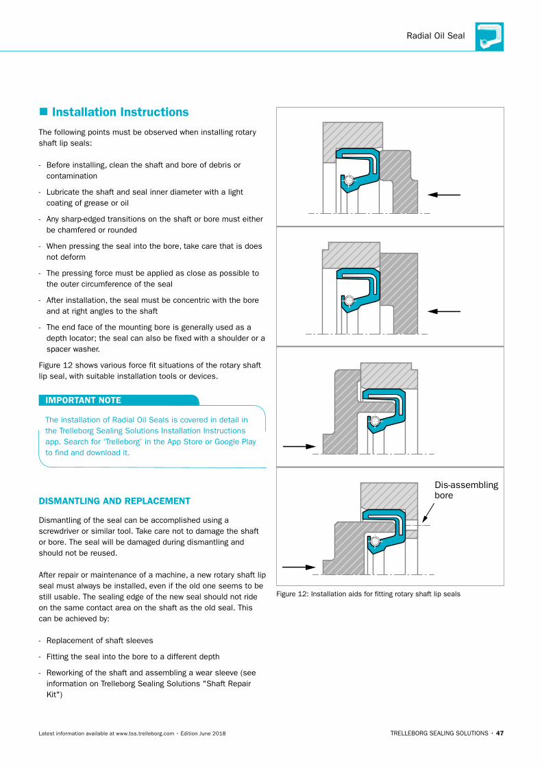
� Installation InstructionsThe following points must be observed when installing rotary shaft lip seals:
- Before installing, clean the shaft and bore of debris or contamination
- Lubricate the shaft and seal inner diameter with a light coating of grease or oil
- Any sharp-edged transitions on the shaft or bore must either be chamfered or rounded
- When pressing the seal into the bore, take care that is does not deform
- The pressing force must be applied as close as possible to the outer circumference of the seal
- After installation, the seal must be concentric with the bore and at right angles to the shaft
- The end face of the mounting bore is generally used as a depth locator; the seal can also be fixed with a shoulder or a spacer washer.
Figure 12 shows various force fit situations of the rotary shaft lip seal, with suitable installation tools or devices.
IMPORTANT NOTE
The installation of Radial Oil Seals is covered in detail in the Trelleborg Sealing Solutions Installation Instructions app. Search for ‘Trelleborg’ in the App Store or Google Play to find and download it.
DISMANTLING AND REPLACEMENT
Dismantling of the seal can be accomplished using a screwdriver or similar tool. Take care not to damage the shaft or bore. The seal will be damaged during dismantling and should not be reused.
After repair or maintenance of a machine, a new rotary shaft lip seal must always be installed, even if the old one seems to be still usable. The sealing edge of the new seal should not ride on the same contact area on the shaft as the old seal. This can be achieved by:
- Replacement of shaft sleeves
- Fitting the seal into the bore to a different depth
- Reworking of the shaft and assembling a wear sleeve (see information on Trelleborg Sealing Solutions "Shaft Repair Kit")
Dis-assemblingbore
Figure 12: Installation aids for fitting rotary shaft lip seals
ROTARY SEALS · Radial Oil Seal
48 • TRELLEBORG SEALING SOLUTIONS Latest information available at www.tss.trelleborg.com • Edition June 2018
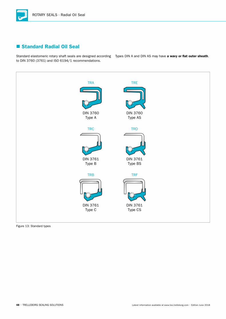
Standard elastomeric rotary shaft seals are designed according to DIN 3760 (3761) and ISO 6194/1 recommendations.
Types DIN A and DIN AS may have a wavy or flat outer sheath.
DIN 3760Type A
TRA
DIN 3761Type B
TRC
DIN 3761Type C
TRB
DIN 3760Type AS
TRE
DIN 3761Type BS
TRD
DIN 3761Type CS
TRF
Figure 13: Standard types
� Standard Radial Oil Seal
Radial Oil Seal
TRELLEBORG SEALING SOLUTIONS • 49Latest information available at www.tss.trelleborg.com • Edition June 2018
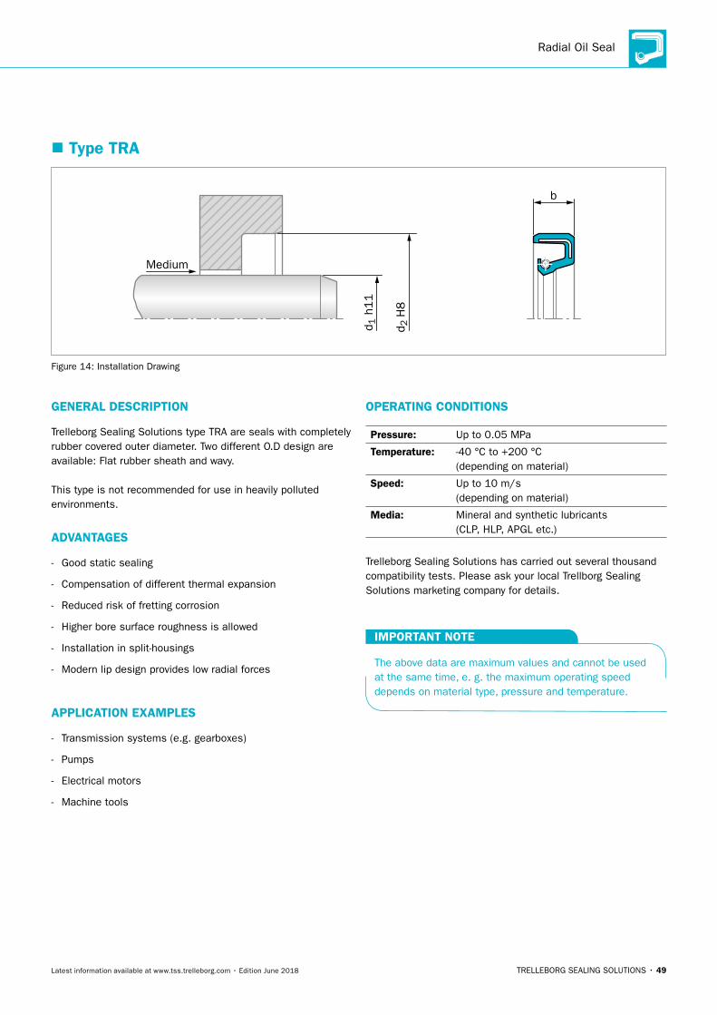
� Type TRA
b
Medium
d 2 H
8
d 1 h
11
Figure 14: Installation Drawing
GENERAL DESCRIPTION
Trelleborg Sealing Solutions type TRA are seals with completely rubber covered outer diameter. Two different O.D design are available: Flat rubber sheath and wavy.
This type is not recommended for use in heavily polluted environments.
ADVANTAGES
- Good static sealing
- Compensation of different thermal expansion
- Reduced risk of fretting corrosion
- Higher bore surface roughness is allowed
- Installation in split-housings
- Modern lip design provides low radial forces
APPLICATION EXAMPLES
- Transmission systems (e.g. gearboxes)
- Pumps
- Electrical motors
- Machine tools
OPERATING CONDITIONS
Pressure: Up to 0.05 MPa
Temperature: -40 °C to +200 °C (depending on material)
Speed: Up to 10 m/s (depending on material)
Media: Mineral and synthetic lubricants (CLP, HLP, APGL etc.)
Trelleborg Sealing Solutions has carried out several thousand compatibility tests. Please ask your local Trellborg Sealing Solutions marketing company for details.
IMPORTANT NOTE
The above data are maximum values and cannot be used at the same time, e. g. the maximum operating speed depends on material type, pressure and temperature.

ROTARY SEALS · Radial Oil Seal
50 • TRELLEBORG SEALING SOLUTIONS Latest information available at www.tss.trelleborg.com • Edition June 2018
Table 6: Materials
TSS Compound Reference Standard Compound Temperature °C Standard Metal Insert Standard Spring
N7MMR NBR (70 Shore A) -30 °C - 100 °C Carbon steel Carbon steel
4N011/4NV11 NBR (75 Shore A) -30 °C - 100 °C Carbon steel Carbon steel
VCBVR FKM (70 Shore A) -20 °C - 200 °C Carbon steel Stainless steel
4V012 FKM (75 Shore A) -20 °C - 200 °C Carbon steel Stainless steel
Special grades and other materials (ACM, EACM, EPDM, HNBR, VMQ) on request. Metal insert and spring can be supplied in different materials on request.
ORDERING EXAMPLE OIL SEAL TSS TYPE
TSS Type: A
Code: TRA
Dimensions: Shaft diameter 25 mm Housing diameter 40 mm Width 7 mm
Material: NBR
Material Code: N7MMR
Material Code (Standard)
Code
TSS Article No. -
Shaft Diameter x 10Quality Index (Standard)
TRA
Execution
00250B N7MMR
Dimension TSS Part No. Material
d1 d2 b NBR FKM
4 12 6 TRA100040
5 16 7 TRA100050
5 19 5 TRA400050
5.5 22 7 TRA000055
6 12 5.5 TRA400060
6 15 4 TRA000060
6 16 5 TRA100060
6 16 7 TRAA00060
7 17 7 TRA200070
7 22 7 TRAA00070
8 14 4 TRA700080
8 16 5 TRA100080
8 16 7 TRA200080
8 18 5 TRA300080
8 20 8 TRA800080
8 22 4 TRA500080
8 22 7 TRAA00080
9 22 7 TRAA00090
9.5 25.4 8 TRA000095
10 18 4 TRA200100
10 19 7 TRA400100
10 20 5 TRAH00100
10 22 6 TRAE00100
Dimension TSS Part No. Material
d1 d2 b NBR FKM
10 22 7 TRAA00100
10 24 7 TRAB00100
10 26 7 TRAC00100
11 19 7 TRA100110
11 26 7 TRAB00110
12 19 5 TRA000120
12 20 5 TRA200120
12 22 4 TRAF00120
12 22 7 TRAA00120
12 24 7 TRAB00120
12 25 5 TRA600120
12 26 7 TRA800120
12 28 7 TRAC00120
12 30 7 TRAD00120
12 32 7 TRAH00120
12 37 10 TRAK00120
13 25 5 TRA100130
13 26 7 TRA200130
13 30 8 TRA300130
14 22 4 TRA000140
14 22 7 TRA400140
In one of the preferred materials In other commercial materials
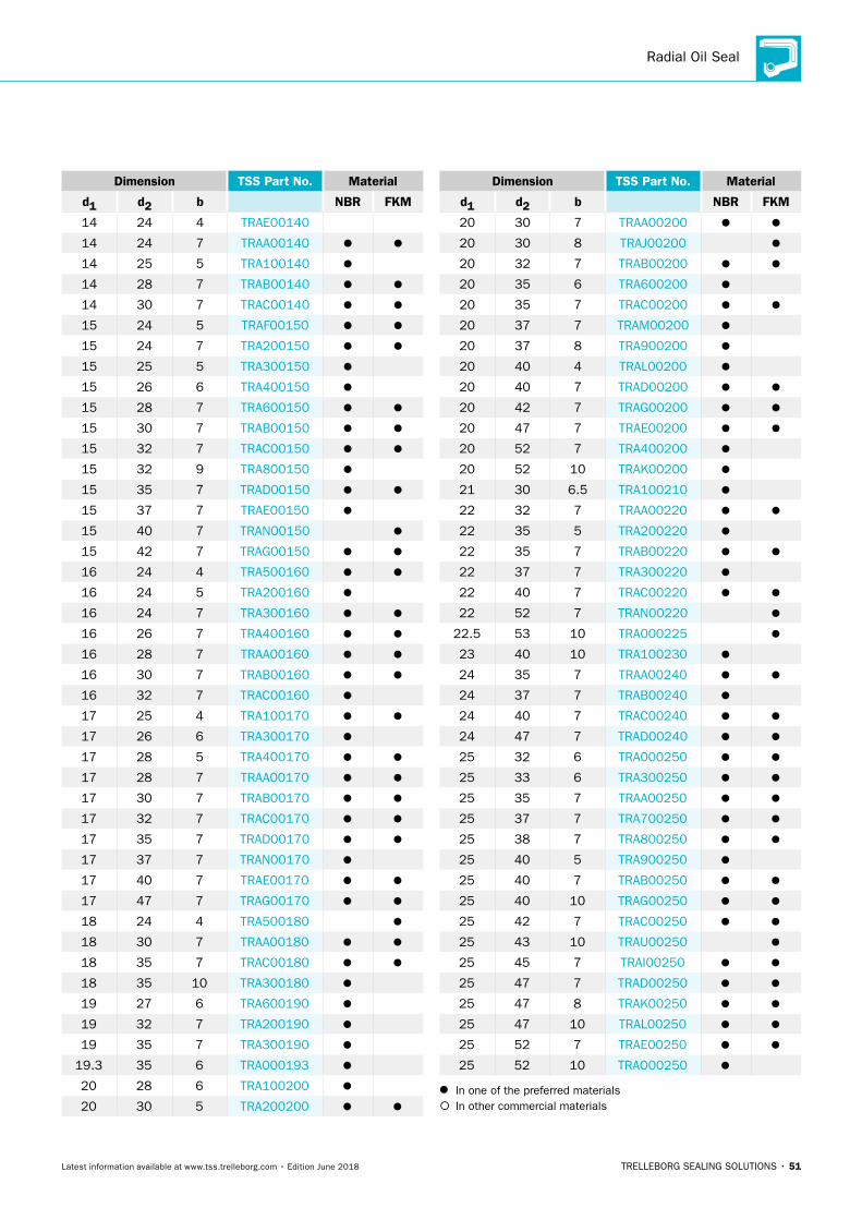
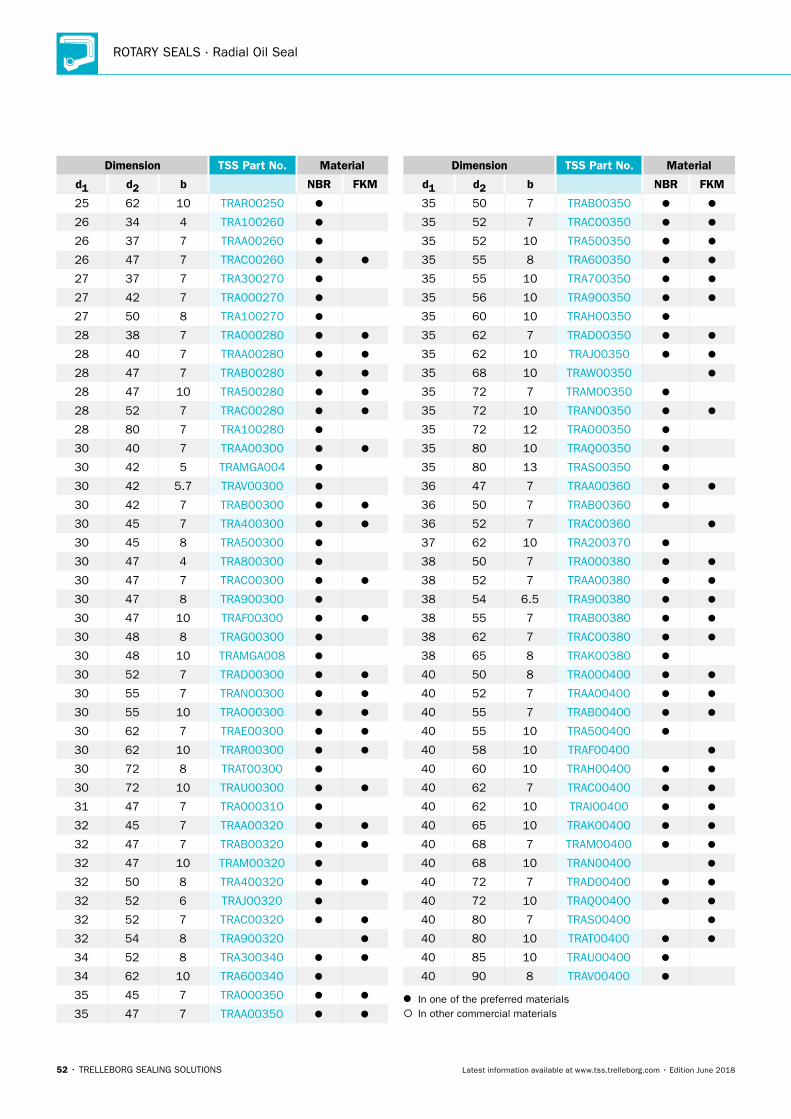
Table 7: Preferred Series / Dimension, TSS Part Numbers
Radial Oil Seal
TRELLEBORG SEALING SOLUTIONS • 51Latest information available at www.tss.trelleborg.com • Edition June 2018
Dimension TSS Part No. Material
d1 d2 b NBR FKM
14 24 4 TRAE00140
14 24 7 TRAA00140
14 25 5 TRA100140
14 28 7 TRAB00140
14 30 7 TRAC00140
15 24 5 TRAF00150
15 24 7 TRA200150
15 25 5 TRA300150
15 26 6 TRA400150
15 28 7 TRA600150
15 30 7 TRAB00150
15 32 7 TRAC00150
15 32 9 TRA800150
15 35 7 TRAD00150
15 37 7 TRAE00150
15 40 7 TRAN00150
15 42 7 TRAG00150
16 24 4 TRA500160
16 24 5 TRA200160
16 24 7 TRA300160
16 26 7 TRA400160
16 28 7 TRAA00160
16 30 7 TRAB00160
16 32 7 TRAC00160
17 25 4 TRA100170
17 26 6 TRA300170
17 28 5 TRA400170
17 28 7 TRAA00170
17 30 7 TRAB00170
17 32 7 TRAC00170
17 35 7 TRAD00170
17 37 7 TRAN00170
17 40 7 TRAE00170
17 47 7 TRAG00170
18 24 4 TRA500180
18 30 7 TRAA00180
18 35 7 TRAC00180
18 35 10 TRA300180
19 27 6 TRA600190
19 32 7 TRA200190
19 35 7 TRA300190
19.3 35 6 TRA000193
20 28 6 TRA100200
20 30 5 TRA200200
Dimension TSS Part No. Material
d1 d2 b NBR FKM
20 30 7 TRAA00200
20 30 8 TRAJ00200
20 32 7 TRAB00200
20 35 6 TRA600200
20 35 7 TRAC00200
20 37 7 TRAM00200
20 37 8 TRA900200
20 40 4 TRAL00200
20 40 7 TRAD00200
20 42 7 TRAG00200
20 47 7 TRAE00200
20 52 7 TRA400200
20 52 10 TRAK00200
21 30 6.5 TRA100210
22 32 7 TRAA00220
22 35 5 TRA200220
22 35 7 TRAB00220
22 37 7 TRA300220
22 40 7 TRAC00220
22 52 7 TRAN00220
22.5 53 10 TRA000225
23 40 10 TRA100230
24 35 7 TRAA00240
24 37 7 TRAB00240
24 40 7 TRAC00240
24 47 7 TRAD00240
25 32 6 TRA000250
25 33 6 TRA300250
25 35 7 TRAA00250
25 37 7 TRA700250
25 38 7 TRA800250
25 40 5 TRA900250
25 40 7 TRAB00250
25 40 10 TRAG00250
25 42 7 TRAC00250
25 43 10 TRAU00250
25 45 7 TRAI00250
25 47 7 TRAD00250
25 47 8 TRAK00250
25 47 10 TRAL00250
25 52 7 TRAE00250
25 52 10 TRAO00250
In one of the preferred materials In other commercial materials
ROTARY SEALS · Radial Oil Seal
52 • TRELLEBORG SEALING SOLUTIONS Latest information available at www.tss.trelleborg.com • Edition June 2018
Dimension TSS Part No. Material
d1 d2 b NBR FKM
25 62 10 TRAR00250
26 34 4 TRA100260
26 37 7 TRAA00260
26 47 7 TRAC00260
27 37 7 TRA300270
27 42 7 TRA000270
27 50 8 TRA100270
28 38 7 TRA000280
28 40 7 TRAA00280
28 47 7 TRAB00280
28 47 10 TRA500280
28 52 7 TRAC00280
28 80 7 TRA100280
30 40 7 TRAA00300
30 42 5 TRAMGA004
30 42 5.7 TRAV00300
30 42 7 TRAB00300
30 45 7 TRA400300
30 45 8 TRA500300
30 47 4 TRA800300
30 47 7 TRAC00300
30 47 8 TRA900300
30 47 10 TRAF00300
30 48 8 TRAG00300
30 48 10 TRAMGA008
30 52 7 TRAD00300
30 55 7 TRAN00300
30 55 10 TRAO00300
30 62 7 TRAE00300
30 62 10 TRAR00300
30 72 8 TRAT00300
30 72 10 TRAU00300
31 47 7 TRA000310
32 45 7 TRAA00320
32 47 7 TRAB00320
32 47 10 TRAM00320
32 50 8 TRA400320
32 52 6 TRAJ00320
32 52 7 TRAC00320
32 54 8 TRA900320
34 52 8 TRA300340
34 62 10 TRA600340
35 45 7 TRA000350
35 47 7 TRAA00350
Dimension TSS Part No. Material
d1 d2 b NBR FKM
35 50 7 TRAB00350
35 52 7 TRAC00350
35 52 10 TRA500350
35 55 8 TRA600350
35 55 10 TRA700350
35 56 10 TRA900350
35 60 10 TRAH00350
35 62 7 TRAD00350
35 62 10 TRAJ00350
35 68 10 TRAW00350
35 72 7 TRAM00350
35 72 10 TRAN00350
35 72 12 TRAO00350
35 80 10 TRAQ00350
35 80 13 TRAS00350
36 47 7 TRAA00360
36 50 7 TRAB00360
36 52 7 TRAC00360
37 62 10 TRA200370
38 50 7 TRA000380
38 52 7 TRAA00380
38 54 6.5 TRA900380
38 55 7 TRAB00380
38 62 7 TRAC00380
38 65 8 TRAK00380
40 50 8 TRA000400
40 52 7 TRAA00400
40 55 7 TRAB00400
40 55 10 TRA500400
40 58 10 TRAF00400
40 60 10 TRAH00400
40 62 7 TRAC00400
40 62 10 TRAI00400
40 65 10 TRAK00400
40 68 7 TRAM00400
40 68 10 TRAN00400
40 72 7 TRAD00400
40 72 10 TRAQ00400
40 80 7 TRAS00400
40 80 10 TRAT00400
40 85 10 TRAU00400
40 90 8 TRAV00400
In one of the preferred materials In other commercial materials
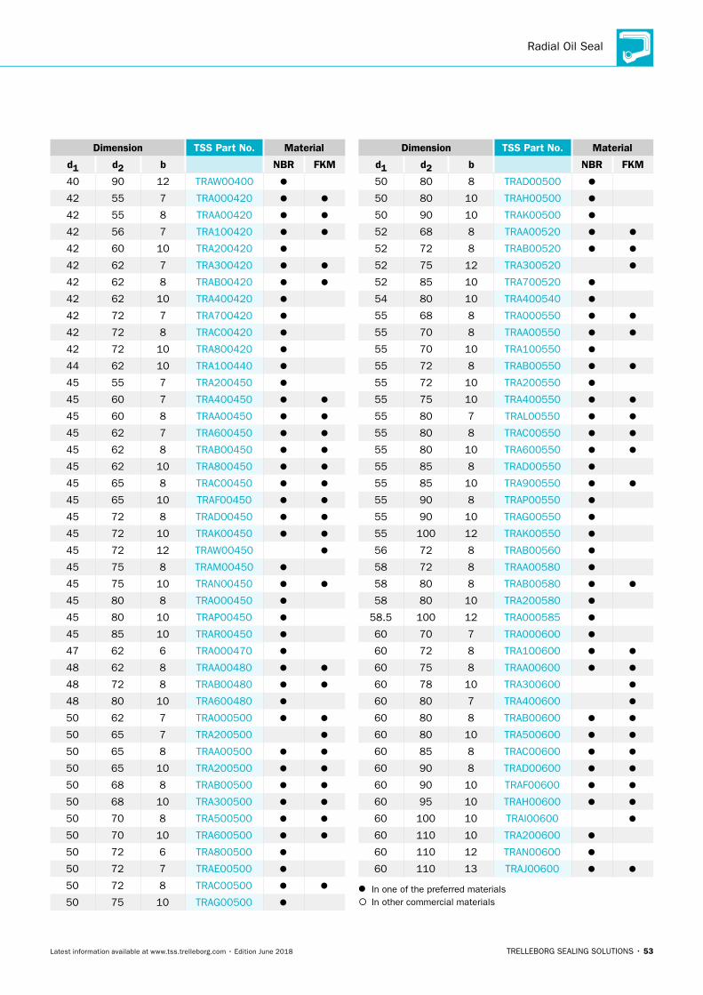
Radial Oil Seal
TRELLEBORG SEALING SOLUTIONS • 53Latest information available at www.tss.trelleborg.com • Edition June 2018
Dimension TSS Part No. Material
d1 d2 b NBR FKM
40 90 12 TRAW00400
42 55 7 TRA000420
42 55 8 TRAA00420
42 56 7 TRA100420
42 60 10 TRA200420
42 62 7 TRA300420
42 62 8 TRAB00420
42 62 10 TRA400420
42 72 7 TRA700420
42 72 8 TRAC00420
42 72 10 TRA800420
44 62 10 TRA100440
45 55 7 TRA200450
45 60 7 TRA400450
45 60 8 TRAA00450
45 62 7 TRA600450
45 62 8 TRAB00450
45 62 10 TRA800450
45 65 8 TRAC00450
45 65 10 TRAF00450
45 72 8 TRAD00450
45 72 10 TRAK00450
45 72 12 TRAW00450
45 75 8 TRAM00450
45 75 10 TRAN00450
45 80 8 TRAO00450
45 80 10 TRAP00450
45 85 10 TRAR00450
47 62 6 TRA000470
48 62 8 TRAA00480
48 72 8 TRAB00480
48 80 10 TRA600480
50 62 7 TRA000500
50 65 7 TRA200500
50 65 8 TRAA00500
50 65 10 TRA200500
50 68 8 TRAB00500
50 68 10 TRA300500
50 70 8 TRA500500
50 70 10 TRA600500
50 72 6 TRA800500
50 72 7 TRAE00500
50 72 8 TRAC00500
50 75 10 TRAG00500
Dimension TSS Part No. Material
d1 d2 b NBR FKM
50 80 8 TRAD00500
50 80 10 TRAH00500
50 90 10 TRAK00500
52 68 8 TRAA00520
52 72 8 TRAB00520
52 75 12 TRA300520
52 85 10 TRA700520
54 80 10 TRA400540
55 68 8 TRA000550
55 70 8 TRAA00550
55 70 10 TRA100550
55 72 8 TRAB00550
55 72 10 TRA200550
55 75 10 TRA400550
55 80 7 TRAL00550
55 80 8 TRAC00550
55 80 10 TRA600550
55 85 8 TRAD00550
55 85 10 TRA900550
55 90 8 TRAP00550
55 90 10 TRAG00550
55 100 12 TRAK00550
56 72 8 TRAB00560
58 72 8 TRAA00580
58 80 8 TRAB00580
58 80 10 TRA200580
58.5 100 12 TRA000585
60 70 7 TRA000600
60 72 8 TRA100600
60 75 8 TRAA00600
60 78 10 TRA300600
60 80 7 TRA400600
60 80 8 TRAB00600
60 80 10 TRA500600
60 85 8 TRAC00600
60 90 8 TRAD00600
60 90 10 TRAF00600
60 95 10 TRAH00600
60 100 10 TRAI00600
60 110 10 TRA200600
60 110 12 TRAN00600
60 110 13 TRAJ00600
In one of the preferred materials In other commercial materials
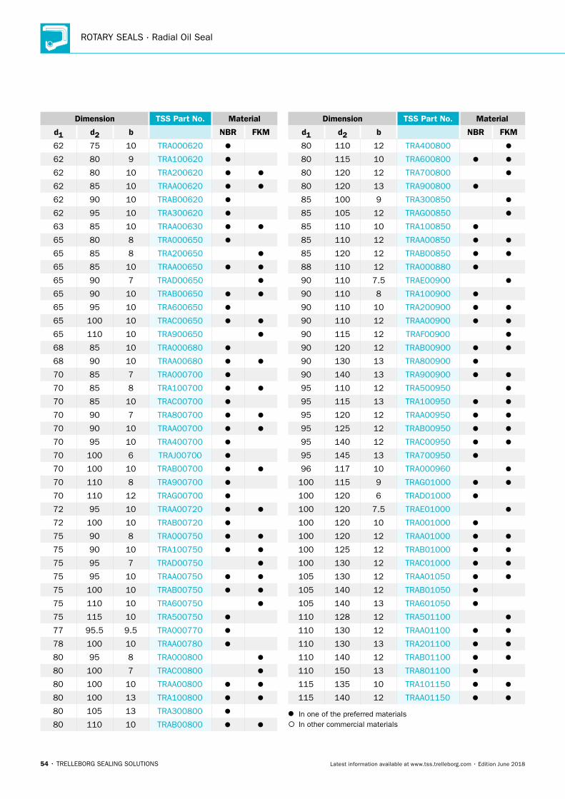
ROTARY SEALS · Radial Oil Seal
54 • TRELLEBORG SEALING SOLUTIONS Latest information available at www.tss.trelleborg.com • Edition June 2018
Dimension TSS Part No. Material
d1 d2 b NBR FKM
62 75 10 TRA000620
62 80 9 TRA100620
62 80 10 TRA200620
62 85 10 TRAA00620
62 90 10 TRAB00620
62 95 10 TRA300620
63 85 10 TRAA00630
65 80 8 TRA000650
65 85 8 TRA200650
65 85 10 TRAA00650
65 90 7 TRAD00650
65 90 10 TRAB00650
65 95 10 TRA600650
65 100 10 TRAC00650
65 110 10 TRA900650
68 85 10 TRA000680
68 90 10 TRAA00680
70 85 7 TRA000700
70 85 8 TRA100700
70 85 10 TRAC00700
70 90 7 TRA800700
70 90 10 TRAA00700
70 95 10 TRA400700
70 100 6 TRAJ00700
70 100 10 TRAB00700
70 110 8 TRA900700
70 110 12 TRAG00700
72 95 10 TRAA00720
72 100 10 TRAB00720
75 90 8 TRA000750
75 90 10 TRA100750
75 95 7 TRAD00750
75 95 10 TRAA00750
75 100 10 TRAB00750
75 110 10 TRA600750
75 115 10 TRA500750
77 95.5 9.5 TRA000770
78 100 10 TRAA00780
80 95 8 TRA000800
80 100 7 TRAC00800
80 100 10 TRAA00800
80 100 13 TRA100800
80 105 13 TRA300800
80 110 10 TRAB00800
Dimension TSS Part No. Material
d1 d2 b NBR FKM
80 110 12 TRA400800
80 115 10 TRA600800
80 120 12 TRA700800
80 120 13 TRA900800
85 100 9 TRA300850
85 105 12 TRAG00850
85 110 10 TRA100850
85 110 12 TRAA00850
85 120 12 TRAB00850
88 110 12 TRA000880
90 110 7.5 TRAE00900
90 110 8 TRA100900
90 110 10 TRA200900
90 110 12 TRAA00900
90 115 12 TRAF00900
90 120 12 TRAB00900
90 130 13 TRA800900
90 140 13 TRA900900
95 110 12 TRA500950
95 115 13 TRA100950
95 120 12 TRAA00950
95 125 12 TRAB00950
95 140 12 TRAC00950
95 145 13 TRA700950
96 117 10 TRA000960
100 115 9 TRAG01000
100 120 6 TRAD01000
100 120 7.5 TRAE01000
100 120 10 TRA001000
100 120 12 TRAA01000
100 125 12 TRAB01000
100 130 12 TRAC01000
105 130 12 TRAA01050
105 140 12 TRAB01050
105 140 13 TRA601050
110 128 12 TRA501100
110 130 12 TRAA01100
110 130 13 TRA201100
110 140 12 TRAB01100
110 150 13 TRA801100
115 135 10 TRA101150
115 140 12 TRAA01150
In one of the preferred materials In other commercial materials
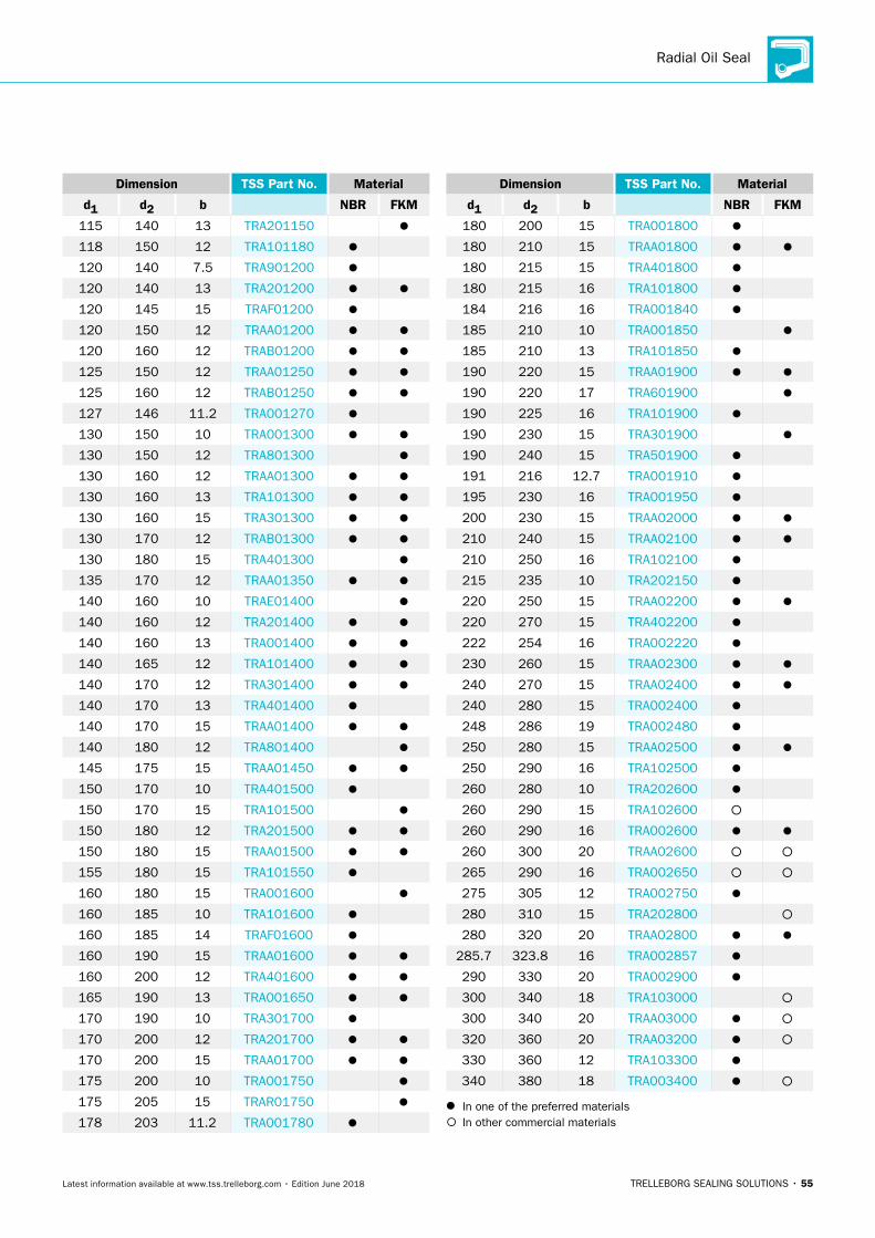
Radial Oil Seal
TRELLEBORG SEALING SOLUTIONS • 55Latest information available at www.tss.trelleborg.com • Edition June 2018
Dimension TSS Part No. Material
d1 d2 b NBR FKM
115 140 13 TRA201150
118 150 12 TRA101180
120 140 7.5 TRA901200
120 140 13 TRA201200
120 145 15 TRAF01200
120 150 12 TRAA01200
120 160 12 TRAB01200
125 150 12 TRAA01250
125 160 12 TRAB01250
127 146 11.2 TRA001270
130 150 10 TRA001300
130 150 12 TRA801300
130 160 12 TRAA01300
130 160 13 TRA101300
130 160 15 TRA301300
130 170 12 TRAB01300
130 180 15 TRA401300
135 170 12 TRAA01350
140 160 10 TRAE01400
140 160 12 TRA201400
140 160 13 TRA001400
140 165 12 TRA101400
140 170 12 TRA301400
140 170 13 TRA401400
140 170 15 TRAA01400
140 180 12 TRA801400
145 175 15 TRAA01450
150 170 10 TRA401500
150 170 15 TRA101500
150 180 12 TRA201500
150 180 15 TRAA01500
155 180 15 TRA101550
160 180 15 TRA001600
160 185 10 TRA101600
160 185 14 TRAF01600
160 190 15 TRAA01600
160 200 12 TRA401600
165 190 13 TRA001650
170 190 10 TRA301700
170 200 12 TRA201700
170 200 15 TRAA01700
175 200 10 TRA001750
175 205 15 TRAR01750
178 203 11.2 TRA001780
Dimension TSS Part No. Material
d1 d2 b NBR FKM
180 200 15 TRA001800
180 210 15 TRAA01800
180 215 15 TRA401800
180 215 16 TRA101800
184 216 16 TRA001840
185 210 10 TRA001850
185 210 13 TRA101850
190 220 15 TRAA01900
190 220 17 TRA601900
190 225 16 TRA101900
190 230 15 TRA301900
190 240 15 TRA501900
191 216 12.7 TRA001910
195 230 16 TRA001950
200 230 15 TRAA02000
210 240 15 TRAA02100
210 250 16 TRA102100
215 235 10 TRA202150
220 250 15 TRAA02200
220 270 15 TRA402200
222 254 16 TRA002220
230 260 15 TRAA02300
240 270 15 TRAA02400
240 280 15 TRA002400
248 286 19 TRA002480
250 280 15 TRAA02500
250 290 16 TRA102500
260 280 10 TRA202600
260 290 15 TRA102600
260 290 16 TRA002600
260 300 20 TRAA02600
265 290 16 TRA002650
275 305 12 TRA002750
280 310 15 TRA202800
280 320 20 TRAA02800
285.7 323.8 16 TRA002857
290 330 20 TRA002900
300 340 18 TRA103000
300 340 20 TRAA03000
320 360 20 TRAA03200
330 360 12 TRA103300
340 380 18 TRA003400
In one of the preferred materials In other commercial materials
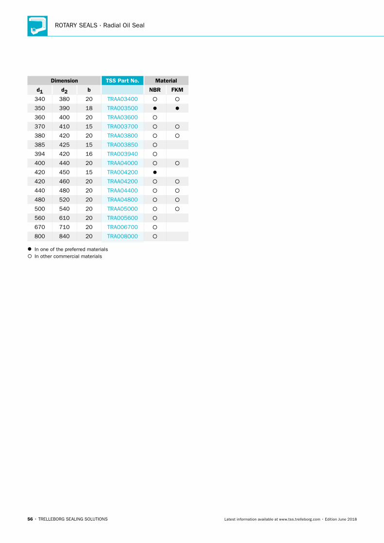
ROTARY SEALS · Radial Oil Seal
56 • TRELLEBORG SEALING SOLUTIONS Latest information available at www.tss.trelleborg.com • Edition June 2018
Dimension TSS Part No. Material
d1 d2 b NBR FKM
340 380 20 TRAA03400
350 390 18 TRA003500
360 400 20 TRAA03600
370 410 15 TRA003700
380 420 20 TRAA03800
385 425 15 TRA003850
394 420 16 TRA003940
400 440 20 TRAA04000
420 450 15 TRA004200
420 460 20 TRAA04200
440 480 20 TRAA04400
480 520 20 TRAA04800
500 540 20 TRAA05000
560 610 20 TRA005600
670 710 20 TRA006700
800 840 20 TRA008000
In one of the preferred materials In other commercial materials
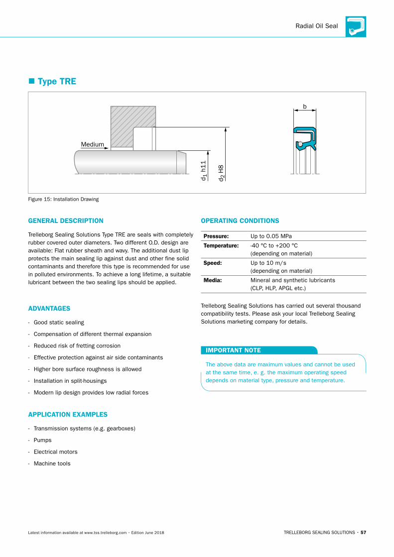
Radial Oil Seal
TRELLEBORG SEALING SOLUTIONS • 57Latest information available at www.tss.trelleborg.com • Edition June 2018
� Type TRE
b
Medium
d 2 H
8
d 1 h
11
Figure 15: Installation Drawing
GENERAL DESCRIPTION
Trelleborg Sealing Solutions Type TRE are seals with completely rubber covered outer diameters. Two different O.D. design are available: Flat rubber sheath and wavy. The additional dust lip protects the main sealing lip against dust and other fine solid contaminants and therefore this type is recommended for use in polluted environments. To achieve a long lifetime, a suitable lubricant between the two sealing lips should be applied.
ADVANTAGES
- Good static sealing
- Compensation of different thermal expansion
- Reduced risk of fretting corrosion
- Effective protection against air side contaminants
- Higher bore surface roughness is allowed
- Installation in split-housings
- Modern lip design provides low radial forces
APPLICATION EXAMPLES
- Transmission systems (e.g. gearboxes)
- Pumps
- Electrical motors
- Machine tools
OPERATING CONDITIONS
Pressure: Up to 0.05 MPa
Temperature: -40 °C to +200 °C (depending on material)
Speed: Up to 10 m/s (depending on material)
Media: Mineral and synthetic lubricants (CLP, HLP, APGL etc.)
Trelleborg Sealing Solutions has carried out several thousand compatibility tests. Please ask your local Trelleborg Sealing Solutions marketing company for details.
IMPORTANT NOTE
The above data are maximum values and cannot be used at the same time, e. g. the maximum operating speed depends on material type, pressure and temperature.
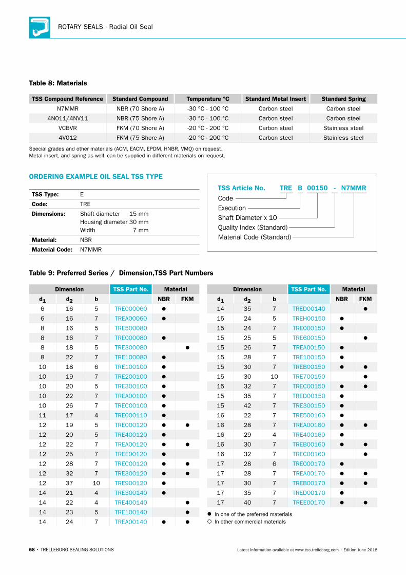
ROTARY SEALS · Radial Oil Seal
58 • TRELLEBORG SEALING SOLUTIONS Latest information available at www.tss.trelleborg.com • Edition June 2018
Table 8: Materials
TSS Compound Reference Standard Compound Temperature °C Standard Metal Insert Standard Spring
N7MMR NBR (70 Shore A) -30 °C - 100 °C Carbon steel Carbon steel
4N011/4NV11 NBR (75 Shore A) -30 °C - 100 °C Carbon steel Carbon steel
VCBVR FKM (70 Shore A) -20 °C - 200 °C Carbon steel Stainless steel
4V012 FKM (75 Shore A) -20 °C - 200 °C Carbon steel Stainless steel
Special grades and other materials (ACM, EACM, EPDM, HNBR, VMQ) on request. Metal insert, and spring as well, can be supplied in different materials on request.
ORDERING EXAMPLE OIL SEAL TSS TYPE
TSS Type: E
Code: TRE
Dimensions: Shaft diameter 15 mm Housing diameter 30 mm Width 7 mm
Material: NBR
Material Code: N7MMR
Material Code (Standard)
Code
TSS Article No. -
Shaft Diameter x 10Quality Index (Standard)
TRE
Execution
00150B N7MMR
Dimension TSS Part No. Material
d1 d2 b NBR FKM
6 16 5 TRE000060
6 16 7 TREA00060
8 16 5 TRE500080
8 16 7 TRE000080
8 18 5 TRE300080
8 22 7 TRE100080
10 18 6 TRE100100
10 19 7 TRE200100
10 20 5 TRE300100
10 22 7 TREA00100
10 26 7 TREC00100
11 17 4 TRE000110
12 19 5 TRE000120
12 20 5 TRE400120
12 22 7 TREA00120
12 25 7 TREE00120
12 28 7 TREC00120
12 32 7 TRE300120
12 37 10 TRE900120
14 21 4 TRE300140
14 22 4 TRE400140
14 23 5 TRE100140
14 24 7 TREA00140
Dimension TSS Part No. Material
d1 d2 b NBR FKM
14 35 7 TRED00140
15 24 5 TREH00150
15 24 7 TRE000150
15 25 5 TRE600150
15 26 7 TREA00150
15 28 7 TRE100150
15 30 7 TREB00150
15 30 10 TRE700150
15 32 7 TREC00150
15 35 7 TRED00150
15 42 7 TRE300150
16 22 7 TRE500160
16 28 7 TREA00160
16 29 4 TRE400160
16 30 7 TREB00160
16 32 7 TREC00160
17 28 6 TRE000170
17 28 7 TREA00170
17 30 7 TREB00170
17 35 7 TRED00170
17 40 7 TREE00170
In one of the preferred materials In other commercial materials
Table 9: Preferred Series / Dimension,TSS Part Numbers
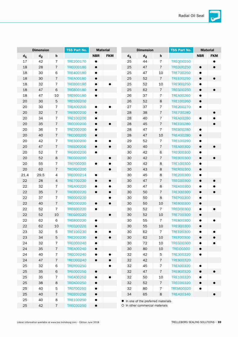
Radial Oil Seal
TRELLEBORG SEALING SOLUTIONS • 59Latest information available at www.tss.trelleborg.com • Edition June 2018
Dimension TSS Part No. Material
d1 d2 b NBR FKM
17 42 7 TRE200170
18 28 7 TRE000180
18 30 6 TRE400180
18 30 7 TREA00180
18 32 7 TREB00180
18 47 6 TRE800180
18 47 10 TRE900180
20 30 5 TRES00200
20 30 7 TREA00200
20 32 7 TREB00200
20 34 7 TRE100200
20 35 7 TREC00200
20 36 7 TRE200200
20 40 7 TRED00200
20 42 7 TRE300200
20 47 7 TREE00200
20 52 7 TRE600200
20 52 8 TREG00200
20 55 7 TREF00200
20 62 7 TRER00200
21.4 29.5 4 TRE000214
22 28 4 TRE700220
22 32 7 TREA00220
22 35 7 TREB00220
22 37 7 TRE000220
22 40 7 TREC00220
22 52 7 TRE600220
22 52 10 TREG00220
22 62 6 TRE800220
22 62 10 TREE00220
23 32 5 TRE100230
23 34 5 TRE200230
24 32 7 TRE000240
24 35 7 TREA00240
24 40 7 TREC00240
24 47 7 TRED00240
25 32 6 TRER00250
25 35 6 TRE000250
25 35 7 TREA00250
25 38 8 TREK00250
25 40 5 TREF00250
25 40 7 TREB00250
25 40 8 TRE100250
25 42 7 TREC00250
Dimension TSS Part No. Material
d1 d2 b NBR FKM
25 44 7 TREQ00250
25 47 7 TRED00250
25 47 10 TRE700250
25 52 7 TREE00250
25 52 10 TRE900250
25 62 7 TREG00250
26 37 7 TREA00260
26 52 8 TRE100260
27 37 7 TRE200270
28 38 7 TRE700280
28 40 7 TREA00280
28 45 7 TREE00280
28 47 7 TREB00280
28 47 10 TRE400280
29 52 7 TRE100290
30 40 7 TREA00300
30 42 6 TRE000300
30 42 7 TREB00300
30 42 8 TRE100300
30 43 8 TRER00300
30 45 8 TRE200300
30 47 7 TREC00300
30 47 8 TREK00300
30 50 7 TRE300300
30 50 8 TREP00300
30 50 10 TRE600300
30 52 7 TRED00300
30 52 10 TRE700300
30 55 7 TRE800300
30 55 10 TRE900300
30 62 7 TREE00300
30 62 10 TREF00300
30 72 10 TREG00300
30 80 10 TREI00300
32 42 5 TRE300320
32 42 7 TRE800320
32 45 7 TREA00320
32 47 7 TREB00320
32 50 10 TRE100320
32 52 7 TREC00320
32 80 7 TREM00320
34 65 8 TRE400340
In one of the preferred materials In other commercial materials
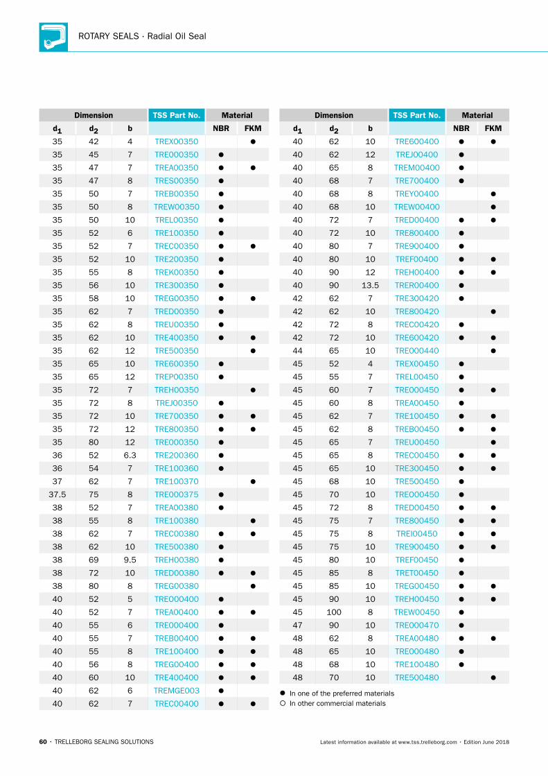
ROTARY SEALS · Radial Oil Seal
60 • TRELLEBORG SEALING SOLUTIONS Latest information available at www.tss.trelleborg.com • Edition June 2018
Dimension TSS Part No. Material
d1 d2 b NBR FKM
35 42 4 TREX00350
35 45 7 TRE000350
35 47 7 TREA00350
35 47 8 TRES00350
35 50 7 TREB00350
35 50 8 TREW00350
35 50 10 TREL00350
35 52 6 TRE100350
35 52 7 TREC00350
35 52 10 TRE200350
35 55 8 TREK00350
35 56 10 TRE300350
35 58 10 TREG00350
35 62 7 TRED00350
35 62 8 TREU00350
35 62 10 TRE400350
35 62 12 TRE500350
35 65 10 TRE600350
35 65 12 TREP00350
35 72 7 TREH00350
35 72 8 TREJ00350
35 72 10 TRE700350
35 72 12 TRE800350
35 80 12 TRE000350
36 52 6.3 TRE200360
36 54 7 TRE100360
37 62 7 TRE100370
37.5 75 8 TRE000375
38 52 7 TREA00380
38 55 8 TRE100380
38 62 7 TREC00380
38 62 10 TRE500380
38 69 9.5 TREH00380
38 72 10 TRED00380
38 80 8 TREG00380
40 52 5 TREO00400
40 52 7 TREA00400
40 55 6 TRE000400
40 55 7 TREB00400
40 55 8 TRE100400
40 56 8 TREG00400
40 60 10 TRE400400
40 62 6 TREMGE003
40 62 7 TREC00400
Dimension TSS Part No. Material
d1 d2 b NBR FKM
40 62 10 TRE600400
40 62 12 TREJ00400
40 65 8 TREM00400
40 68 7 TRE700400
40 68 8 TREY00400
40 68 10 TREW00400
40 72 7 TRED00400
40 72 10 TRE800400
40 80 7 TRE900400
40 80 10 TREF00400
40 90 12 TREH00400
40 90 13.5 TRER00400
42 62 7 TRE300420
42 62 10 TRE800420
42 72 8 TREC00420
42 72 10 TRE600420
44 65 10 TRE000440
45 52 4 TREX00450
45 55 7 TREL00450
45 60 7 TRE000450
45 60 8 TREA00450
45 62 7 TRE100450
45 62 8 TREB00450
45 65 7 TREU00450
45 65 8 TREC00450
45 65 10 TRE300450
45 68 10 TRE500450
45 70 10 TREO00450
45 72 8 TRED00450
45 75 7 TRE800450
45 75 8 TREI00450
45 75 10 TRE900450
45 80 10 TREF00450
45 85 8 TRET00450
45 85 10 TREG00450
45 90 10 TREH00450
45 100 8 TREW00450
47 90 10 TRE000470
48 62 8 TREA00480
48 65 10 TRE000480
48 68 10 TRE100480
48 70 10 TRE500480
In one of the preferred materials In other commercial materials
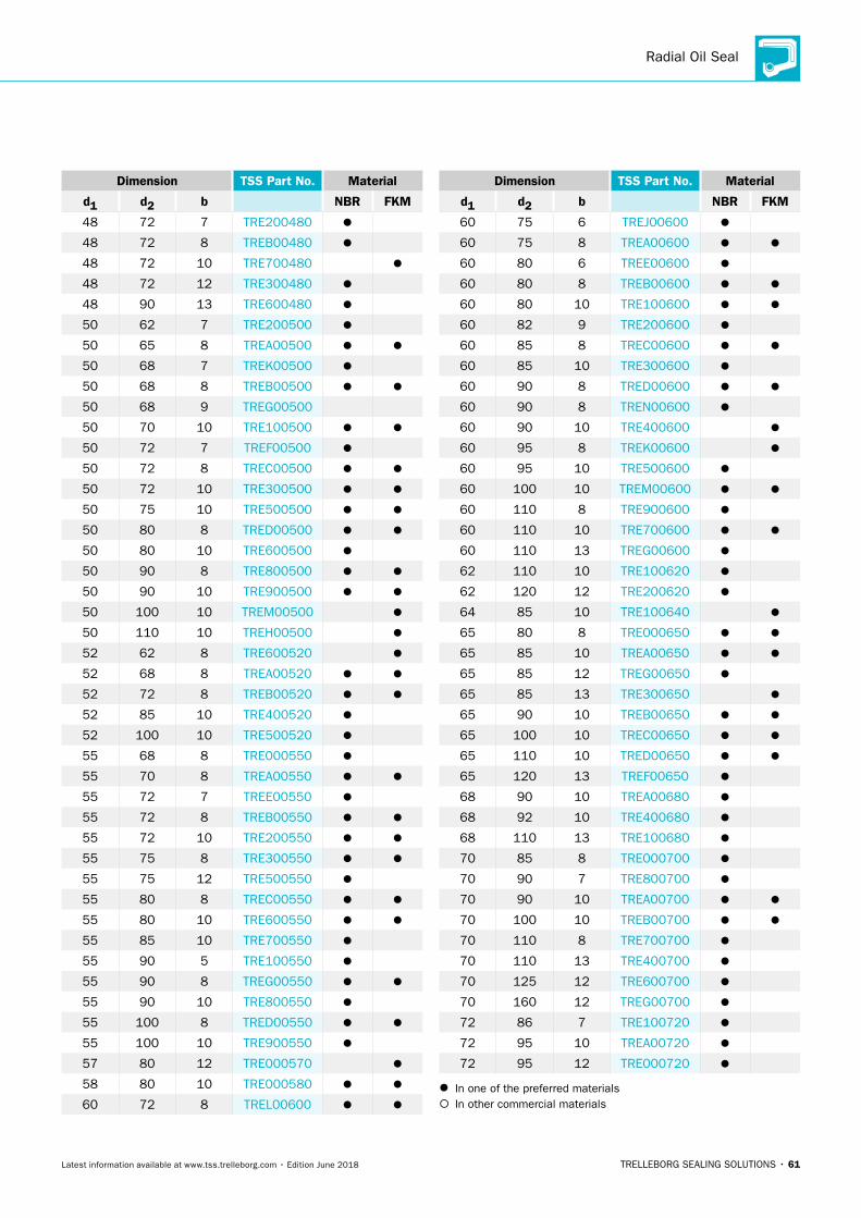
Radial Oil Seal
TRELLEBORG SEALING SOLUTIONS • 61Latest information available at www.tss.trelleborg.com • Edition June 2018
Dimension TSS Part No. Material
d1 d2 b NBR FKM
48 72 7 TRE200480
48 72 8 TREB00480
48 72 10 TRE700480
48 72 12 TRE300480
48 90 13 TRE600480
50 62 7 TRE200500
50 65 8 TREA00500
50 68 7 TREK00500
50 68 8 TREB00500
50 68 9 TREG00500
50 70 10 TRE100500
50 72 7 TREF00500
50 72 8 TREC00500
50 72 10 TRE300500
50 75 10 TRE500500
50 80 8 TRED00500
50 80 10 TRE600500
50 90 8 TRE800500
50 90 10 TRE900500
50 100 10 TREM00500
50 110 10 TREH00500
52 62 8 TRE600520
52 68 8 TREA00520
52 72 8 TREB00520
52 85 10 TRE400520
52 100 10 TRE500520
55 68 8 TRE000550
55 70 8 TREA00550
55 72 7 TREE00550
55 72 8 TREB00550
55 72 10 TRE200550
55 75 8 TRE300550
55 75 12 TRE500550
55 80 8 TREC00550
55 80 10 TRE600550
55 85 10 TRE700550
55 90 5 TRE100550
55 90 8 TREG00550
55 90 10 TRE800550
55 100 8 TRED00550
55 100 10 TRE900550
57 80 12 TRE000570
58 80 10 TRE000580
60 72 8 TREL00600
Dimension TSS Part No. Material
d1 d2 b NBR FKM
60 75 6 TREJ00600
60 75 8 TREA00600
60 80 6 TREE00600
60 80 8 TREB00600
60 80 10 TRE100600
60 82 9 TRE200600
60 85 8 TREC00600
60 85 10 TRE300600
60 90 8 TRED00600
60 90 8 TREN00600
60 90 10 TRE400600
60 95 8 TREK00600
60 95 10 TRE500600
60 100 10 TREM00600
60 110 8 TRE900600
60 110 10 TRE700600
60 110 13 TREG00600
62 110 10 TRE100620
62 120 12 TRE200620
64 85 10 TRE100640
65 80 8 TRE000650
65 85 10 TREA00650
65 85 12 TREG00650
65 85 13 TRE300650
65 90 10 TREB00650
65 100 10 TREC00650
65 110 10 TRED00650
65 120 13 TREF00650
68 90 10 TREA00680
68 92 10 TRE400680
68 110 13 TRE100680
70 85 8 TRE000700
70 90 7 TRE800700
70 90 10 TREA00700
70 100 10 TREB00700
70 110 8 TRE700700
70 110 13 TRE400700
70 125 12 TRE600700
70 160 12 TREG00700
72 86 7 TRE100720
72 95 10 TREA00720
72 95 12 TRE000720
In one of the preferred materials In other commercial materials
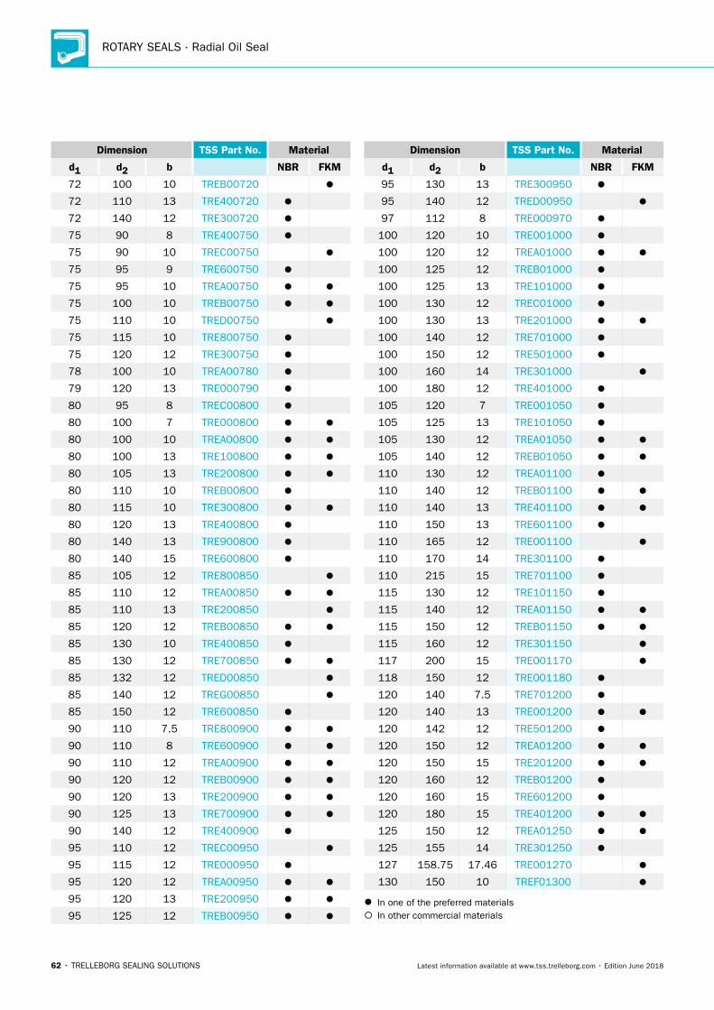
ROTARY SEALS · Radial Oil Seal
62 • TRELLEBORG SEALING SOLUTIONS Latest information available at www.tss.trelleborg.com • Edition June 2018
Dimension TSS Part No. Material
d1 d2 b NBR FKM
72 100 10 TREB00720
72 110 13 TRE400720
72 140 12 TRE300720
75 90 8 TRE400750
75 90 10 TREC00750
75 95 9 TRE600750
75 95 10 TREA00750
75 100 10 TREB00750
75 110 10 TRED00750
75 115 10 TRE800750
75 120 12 TRE300750
78 100 10 TREA00780
79 120 13 TRE000790
80 95 8 TREC00800
80 100 7 TRE000800
80 100 10 TREA00800
80 100 13 TRE100800
80 105 13 TRE200800
80 110 10 TREB00800
80 115 10 TRE300800
80 120 13 TRE400800
80 140 13 TRE900800
80 140 15 TRE600800
85 105 12 TRE800850
85 110 12 TREA00850
85 110 13 TRE200850
85 120 12 TREB00850
85 130 10 TRE400850
85 130 12 TRE700850
85 132 12 TRED00850
85 140 12 TREG00850
85 150 12 TRE600850
90 110 7.5 TRE800900
90 110 8 TRE600900
90 110 12 TREA00900
90 120 12 TREB00900
90 120 13 TRE200900
90 125 13 TRE700900
90 140 12 TRE400900
95 110 12 TREC00950
95 115 12 TRE000950
95 120 12 TREA00950
95 120 13 TRE200950
95 125 12 TREB00950
Dimension TSS Part No. Material
d1 d2 b NBR FKM
95 130 13 TRE300950
95 140 12 TRED00950
97 112 8 TRE000970
100 120 10 TRE001000
100 120 12 TREA01000
100 125 12 TREB01000
100 125 13 TRE101000
100 130 12 TREC01000
100 130 13 TRE201000
100 140 12 TRE701000
100 150 12 TRE501000
100 160 14 TRE301000
100 180 12 TRE401000
105 120 7 TRE001050
105 125 13 TRE101050
105 130 12 TREA01050
105 140 12 TREB01050
110 130 12 TREA01100
110 140 12 TREB01100
110 140 13 TRE401100
110 150 13 TRE601100
110 165 12 TRE001100
110 170 14 TRE301100
110 215 15 TRE701100
115 130 12 TRE101150
115 140 12 TREA01150
115 150 12 TREB01150
115 160 12 TRE301150
117 200 15 TRE001170
118 150 12 TRE001180
120 140 7.5 TRE701200
120 140 13 TRE001200
120 142 12 TRE501200
120 150 12 TREA01200
120 150 15 TRE201200
120 160 12 TREB01200
120 160 15 TRE601200
120 180 15 TRE401200
125 150 12 TREA01250
125 155 14 TRE301250
127 158.75 17.46 TRE001270
130 150 10 TREF01300
In one of the preferred materials In other commercial materials
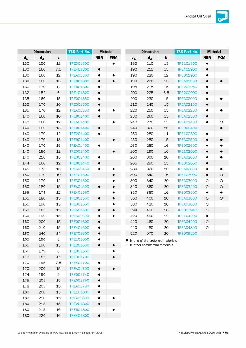
Radial Oil Seal
TRELLEBORG SEALING SOLUTIONS • 63Latest information available at www.tss.trelleborg.com • Edition June 2018
Dimension TSS Part No. Material
d1 d2 b NBR FKM
130 150 12 TRE301300
130 160 7.5 TRE401300
130 160 12 TREA01300
130 160 15 TRE001300
130 170 12 TREB01300
132 152 6 TRE101320
135 160 15 TRE001350
135 170 10 TRE301350
135 170 12 TREA01350
140 160 10 TRE801400
140 160 12 TRE601400
140 160 13 TRE001400
140 170 12 TRE201400
140 170 13 TRE901400
140 170 15 TREA01400
140 180 12 TRE501400
140 210 15 TRE301400
144 160 12 TRE001440
145 175 15 TREA01450
150 170 10 TRE101500
150 170 12 TRE301500
150 180 15 TREA01500
155 174 12 TRE401550
155 180 15 TRE001550
155 190 13 TRE301550
160 185 15 TRE601600
160 190 15 TREA01600
160 200 15 TRE001600
160 210 15 TRE401600
160 240 14 TRE701600
165 190 8 TRE101650
165 190 13 TRE201650
166 179 8 TRE001660
170 185 9.5 TRE301700
170 195 7.5 TRE401700
170 200 15 TREA01700
174 190 5 TRE001740
175 205 15 TRE001750
178 205 15 TREA01780
180 200 13 TRE101800
180 210 15 TREA01800
180 215 15 TRE201800
180 215 16 TRE501800
180 220 16 TRE401800
Dimension TSS Part No. Material
d1 d2 b NBR FKM
185 210 13 TRE101850
190 215 15 TRE401900
190 220 12 TRE001900
190 220 15 TREA01900
195 215 15 TRE201950
200 225 8.5 TRE202000
200 230 15 TREA02000
210 240 15 TREA02100
220 250 15 TREA02200
230 260 15 TREA02300
240 270 15 TREA02400
240 320 20 TRE002400
250 280 11 TRE102500
250 280 15 TREA02500
260 280 16 TRE002600
260 290 16 TRE102600
260 300 20 TREA02600
265 290 15 TRE002650
280 320 20 TREA02800
300 340 16 TRE103000
300 340 20 TREA03000
320 360 20 TREA03200
350 380 16 TRE003500
360 400 20 TREA03600
380 420 20 TREA03800
394 420 16 TRE003940
420 450 12 TRE104200
420 460 20 TREA04200
440 480 20 TREA04800
920 970 20 TRE009200
In one of the preferred materials In other commercial materials
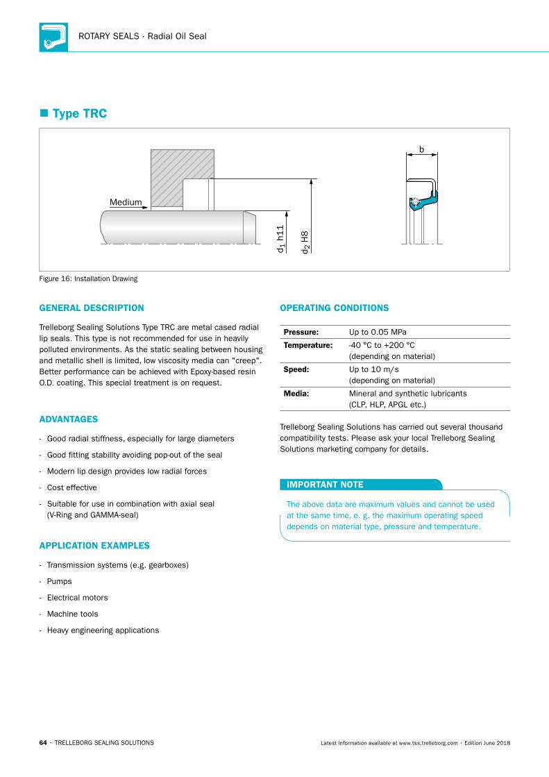
ROTARY SEALS · Radial Oil Seal
64 • TRELLEBORG SEALING SOLUTIONS Latest information available at www.tss.trelleborg.com • Edition June 2018
� Type TRC
b
Medium
d 2 H
8
d 1 h
11
Figure 16: Installation Drawing
GENERAL DESCRIPTION
Trelleborg Sealing Solutions Type TRC are metal cased radial lip seals. This type is not recommended for use in heavily polluted environments. As the static sealing between housing and metallic shell is limited, low viscosity media can "creep". Better performance can be achieved with Epoxy-based resin O.D. coating. This special treatment is on request.
ADVANTAGES
- Good radial stiffness, especially for large diameters
- Good fitting stability avoiding pop-out of the seal
- Modern lip design provides low radial forces
- Cost effective
- Suitable for use in combination with axial seal (V-Ring and GAMMA-seal)
APPLICATION EXAMPLES
- Transmission systems (e.g. gearboxes)
- Pumps
- Electrical motors
- Machine tools
- Heavy engineering applications
OPERATING CONDITIONS
Pressure: Up to 0.05 MPa
Temperature: -40 °C to +200 °C (depending on material)
Speed: Up to 10 m/s (depending on material)
Media: Mineral and synthetic lubricants (CLP, HLP, APGL etc.)
Trelleborg Sealing Solutions has carried out several thousand compatibility tests. Please ask your local Trelleborg Sealing Solutions marketing company for details.
IMPORTANT NOTE
The above data are maximum values and cannot be used at the same time, e. g. the maximum operating speed depends on material type, pressure and temperature.
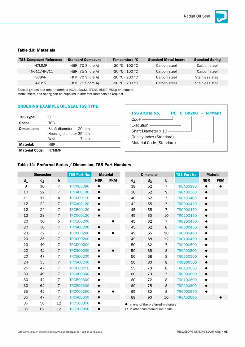
Radial Oil Seal
TRELLEBORG SEALING SOLUTIONS • 65Latest information available at www.tss.trelleborg.com • Edition June 2018
Table 10: Materials
TSS Compound Reference Standard Compound Temperature °C Standard Metal Insert Standard Spring
N7MMR NBR (70 Shore A) -30 °C - 100 °C Carbon steel Carbon steel
4N011/4NV11 NBR (75 Shore A) -30 °C - 100 °C Carbon steel Carbon steel
VCBVR FKM (70 Shore A) -20 °C - 200 °C Carbon steel Stainless steel
4V012 FKM (75 Shore A) -20 °C - 200 °C Carbon steel Stainless steel
Special grades and other materials (ACM, EACM, EPDM, HNBR, VMQ) on request. Metal insert, and spring can be supplied in different materials on request.
ORDERING EXAMPLE OIL SEAL TSS TYPE
TSS Type: C
Code: TRC
Dimensions: Shaft diameter 20 mm Housing diameter 35 mm Width 7 mm
Material: NBR
Material Code: N7MMR
Material Code (Standard)
Code
TSS Article No. -
Shaft Diameter x 10Quality Index (Standard)
TRC
Execution
00200C N7MMR
Table 11: Preferred Series / Dimension, TSS Part Numbers
Dimension TSS Part No. Material
d1 d2 b NBR FKM
8 16 7 TRC000080
10 22 7 TRCA00100
11 17 4 TRC000110
12 22 7 TRCA00120
12 24 7 TRCB00120
12 28 7 TRCC00120
20 30 5 TRC100200
20 30 7 TRCA00200
20 32 7 TRCB00200
20 35 7 TRCC00200
20 40 7 TRCD00200
20 42 7 TRC300200
20 47 7 TRCE00200
24 35 7 TRCA00240
25 47 7 TRCD00250
30 40 7 TRCA00300
30 42 7 TRCB00300
30 62 7 TRCE00300
35 45 7 TRC000350
35 47 7 TRCA00350
35 56 12 TRC500350
35 62 12 TRC700350
Dimension TSS Part No. Material
d1 d2 b NBR FKM
38 52 7 TRCA00380
38 52 9 TRC400380
40 52 7 TRCA00400
42 55 7 TRC000420
45 55 7 TRC000450
45 60 10 TRC200450
45 62 7 TRC300450
45 62 8 TRCB00450
49 65 10 TRC000490
49 68 12 TRC100490
50 62 7 TRC000500
50 65 8 TRCA00500
50 68 8 TRCB00500
50 80 8 TRCD00500
55 70 8 TRCA00550
60 70 7 TRC000600
60 72 8 TRC100600
60 75 8 TRCA00600
65 80 8 TRC000650
68 90 10 TRCA00680
In one of the preferred materials In other commercial materials
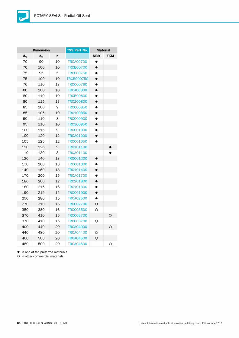
ROTARY SEALS · Radial Oil Seal
66 • TRELLEBORG SEALING SOLUTIONS Latest information available at www.tss.trelleborg.com • Edition June 2018
Dimension TSS Part No. Material
d1 d2 b NBR FKM
70 90 10 TRCA00700
70 100 10 TRCB00700
75 95 5 TRC000750
75 100 10 TRCB000750
76 110 13 TRC000760
80 100 10 TRCA00800
80 110 10 TRCB00800
80 115 13 TRC200800
85 100 9 TRC000850
85 105 10 TRC100850
90 110 8 TRC000900
95 110 10 TRC300950
100 115 9 TRC001000
100 120 12 TRCA01000
105 125 12 TRC001050
110 126 9 TRC101100
110 130 8 TRC301100
120 140 13 TRC001200
130 160 13 TRC001300
140 160 13 TRC101400
170 200 15 TRCA01700
180 200 12 TRC201800
180 215 16 TRC101800
190 215 15 TRC001900
250 280 15 TRCA02500
270 310 16 TRC002700
350 380 16 TRC003500
370 410 15 TRC003700
370 410 15 TRC003700
400 440 20 TRCA04000
440 480 20 TRCA04400
460 500 20 TRCA04600
460 500 20 TRCA04600
In one of the preferred materials In other commercial materials
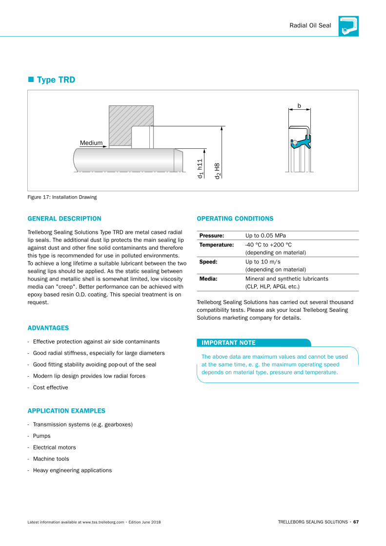
Radial Oil Seal
TRELLEBORG SEALING SOLUTIONS • 67Latest information available at www.tss.trelleborg.com • Edition June 2018
� Type TRD
b
Medium
d 2 H
8
d 1 h
11
Figure 17: Installation Drawing
GENERAL DESCRIPTION
Trelleborg Sealing Solutions Type TRD are metal cased radial lip seals. The additional dust lip protects the main sealing lip against dust and other fine solid contaminants and therefore this type is recommended for use in polluted environments. To achieve a long lifetime a suitable lubricant between the two sealing lips should be applied. As the static sealing between housing and metallic shell is somewhat limited, low viscosity media can "creep". Better performance can be achieved with epoxy based resin O.D. coating. This special treatment is on request.
ADVANTAGES
- Effective protection against air side contaminants
- Good radial stiffness, especially for large diameters
- Good fitting stability avoiding pop-out of the seal
- Modern lip design provides low radial forces
- Cost effective
APPLICATION EXAMPLES
- Transmission systems (e.g. gearboxes)
- Pumps
- Electrical motors
- Machine tools
- Heavy engineering applications
OPERATING CONDITIONS
Pressure: Up to 0.05 MPa
Temperature: -40 °C to +200 °C (depending on material)
Speed: Up to 10 m/s (depending on material)
Media: Mineral and synthetic lubricants (CLP, HLP, APGL etc.)
Trelleborg Sealing Solutions has carried out several thousand compatibility tests. Please ask your local Trelleborg Sealing Solutions marketing company for details.
IMPORTANT NOTE
The above data are maximum values and cannot be used at the same time, e. g. the maximum operating speed depends on material type, pressure and temperature.
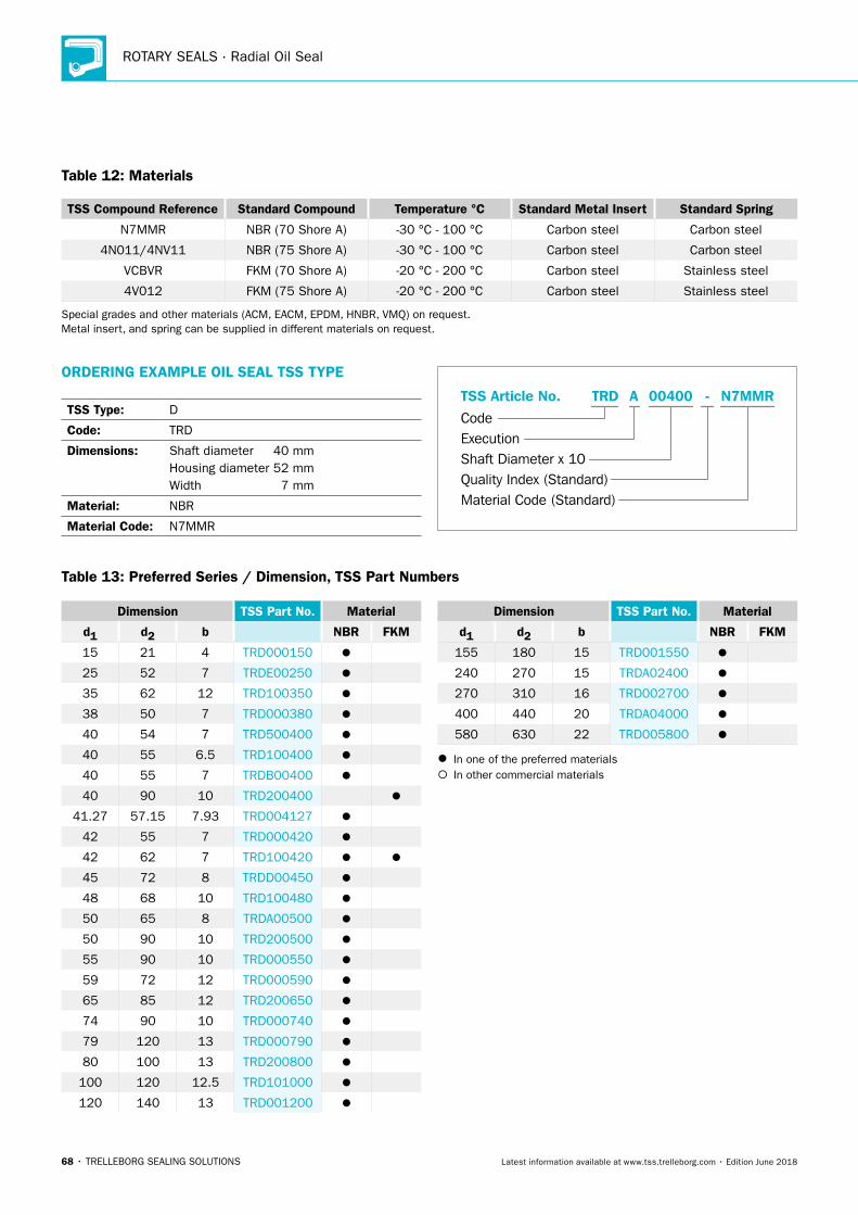
ROTARY SEALS · Radial Oil Seal
68 • TRELLEBORG SEALING SOLUTIONS Latest information available at www.tss.trelleborg.com • Edition June 2018
Table 12: Materials
TSS Compound Reference Standard Compound Temperature °C Standard Metal Insert Standard Spring
N7MMR NBR (70 Shore A) -30 °C - 100 °C Carbon steel Carbon steel
4N011/4NV11 NBR (75 Shore A) -30 °C - 100 °C Carbon steel Carbon steel
VCBVR FKM (70 Shore A) -20 °C - 200 °C Carbon steel Stainless steel
4V012 FKM (75 Shore A) -20 °C - 200 °C Carbon steel Stainless steel
Special grades and other materials (ACM, EACM, EPDM, HNBR, VMQ) on request. Metal insert, and spring can be supplied in different materials on request.
ORDERING EXAMPLE OIL SEAL TSS TYPE
TSS Type: D
Code: TRD
Dimensions: Shaft diameter 40 mm Housing diameter 52 mm Width 7 mm
Material: NBR
Material Code: N7MMR
Material Code (Standard)
Code
TSS Article No. -
Shaft Diameter x 10Quality Index (Standard)
TRD
Execution
00400A N7MMR
Dimension TSS Part No. Material
d1 d2 b NBR FKM
15 21 4 TRD000150
25 52 7 TRDE00250
35 62 12 TRD100350
38 50 7 TRD000380
40 54 7 TRD500400
40 55 6.5 TRD100400
40 55 7 TRDB00400
40 90 10 TRD200400
41.27 57.15 7.93 TRD004127
42 55 7 TRD000420
42 62 7 TRD100420
45 72 8 TRDD00450
48 68 10 TRD100480
50 65 8 TRDA00500
50 90 10 TRD200500
55 90 10 TRD000550
59 72 12 TRD000590
65 85 12 TRD200650
74 90 10 TRD000740
79 120 13 TRD000790
80 100 13 TRD200800
100 120 12.5 TRD101000
120 140 13 TRD001200
Dimension TSS Part No. Material
d1 d2 b NBR FKM
155 180 15 TRD001550
240 270 15 TRDA02400
270 310 16 TRD002700
400 440 20 TRDA04000
580 630 22 TRD005800
In one of the preferred materials In other commercial materials
Table 13: Preferred Series / Dimension, TSS Part Numbers
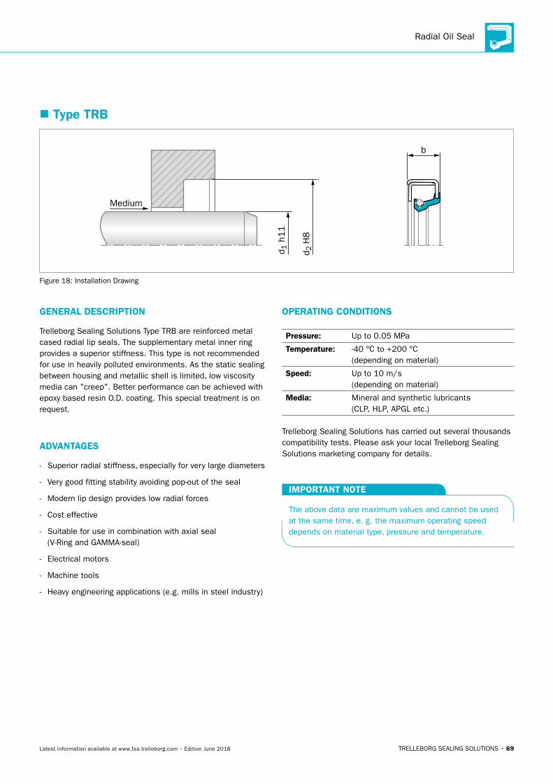
Radial Oil Seal
TRELLEBORG SEALING SOLUTIONS • 69Latest information available at www.tss.trelleborg.com • Edition June 2018
� Type TRB
b
Medium
d 2 H
8
d 1 h
11
Figure 18: Installation Drawing
GENERAL DESCRIPTION
Trelleborg Sealing Solutions Type TRB are reinforced metal cased radial lip seals. The supplementary metal inner ring provides a superior stiffness. This type is not recommended for use in heavily polluted environments. As the static sealing between housing and metallic shell is limited, low viscosity media can "creep". Better performance can be achieved with epoxy based resin O.D. coating. This special treatment is on request.
ADVANTAGES
- Superior radial stiffness, especially for very large diameters
- Very good fitting stability avoiding pop-out of the seal
- Modern lip design provides low radial forces
- Cost effective
- Suitable for use in combination with axial seal (V-Ring and GAMMA-seal)
- Electrical motors
- Machine tools
- Heavy engineering applications (e.g. mills in steel industry)
OPERATING CONDITIONS
Pressure: Up to 0.05 MPa
Temperature: -40 °C to +200 °C (depending on material)
Speed: Up to 10 m/s (depending on material)
Media: Mineral and synthetic lubricants (CLP, HLP, APGL etc.)
Trelleborg Sealing Solutions has carried out several thousands compatibility tests. Please ask your local Trelleborg Sealing Solutions marketing company for details.
IMPORTANT NOTE
The above data are maximum values and cannot be used at the same time, e. g. the maximum operating speed depends on material type, pressure and temperature.
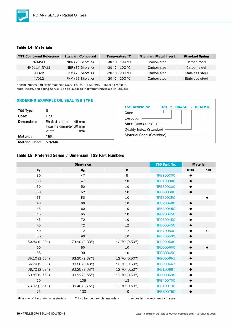
ROTARY SEALS · Radial Oil Seal
70 • TRELLEBORG SEALING SOLUTIONS Latest information available at www.tss.trelleborg.com • Edition June 2018
Table 14: Materials
TSS Compound Reference Standard Compound Temperature °C Standard Metal Insert Standard Spring
N7MMR NBR (70 Shore A) -30 °C - 100 °C Carbon steel Carbon steel
4N011/4NV11 NBR (75 Shore A) -30 °C - 100 °C Carbon steel Carbon steel
VCBVR FKM (70 Shore A) -20 °C - 200 °C Carbon steel Stainless steel
4V012 FKM (75 Shore A) -20 °C - 200 °C Carbon steel Stainless steel
Special grades and other materials (ACM, EACM, EPDM, HNBR, VMQ) on request. Metal insert, and spring as well, can be supplied in different materials on request.
ORDERING EXAMPLE OIL SEAL TSS TYPE
TSS Type: B
Code: TRB
Dimensions: Shaft diameter 45 mm Housing diameter 60 mm Width 7 mm
Material: NBR
Material Code: N7MMR
Material Code (Standard)
Code
TSS Article No. -
Shaft Diameter x 10Quality Index (Standard)
TRB
Execution
004505 N7MMR
Table 15: Preferred Series / Dimension, TSS Part Numbers
Dimension TSS Part No. Material
d1 d2 b NBR FKM
30 47 9 TRB800300
30 47 10 TRB100300
30 50 10 TRB300300
30 62 10 TRB600300
35 56 10 TRB300350
40 60 10 TRB200400
45 60 10 TRB500450
45 65 10 TRB200450
45 72 10 TRB600450
45 72 12 TRB000450
50 72 12 TRB700500
50 90 10 TRBE00500
50.80 (2.00'') 73.10 (2.88'') 12.70 (0.50'') TRB000508
60 80 10 TRB000600
65 90 10 TRBB00650
65.10 (2.56'') 92.20 (3.63'') 12.70 (0.50'') TRB000651
66.70 (2.63'') 88.50 (3.48'') 12.70 (0.50'') TRB000667
66.70 (2.63'') 92.20 (3.63'') 12.70 (0.50'') TRB100667
69.85 (2.75'') 90.12 (3.55'') 12.70 (0.50'') TRB000698
70 105 13 TRB400700
73.02 (2.87'') 95.40 (3.76'') 12.70 (0.50'') TRB100730
75 100 10 TRBB00750
In one of the preferred materials In other commercial materials Values in brackets are inch sizes.
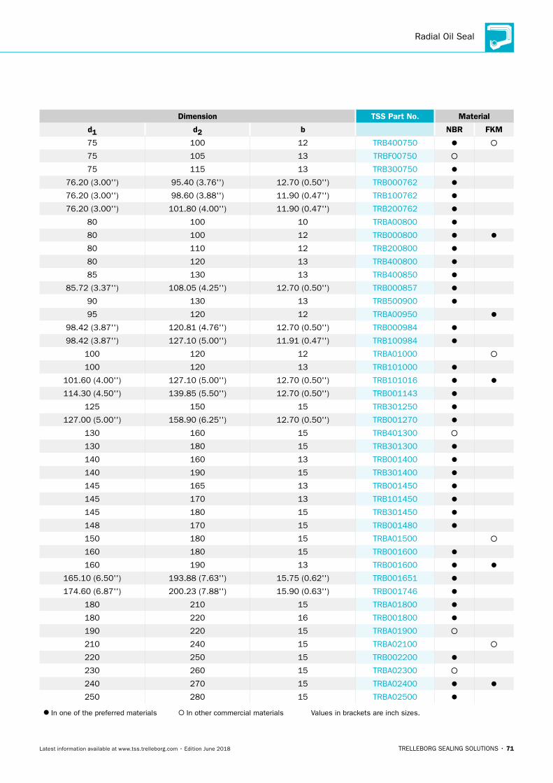
Radial Oil Seal
TRELLEBORG SEALING SOLUTIONS • 71Latest information available at www.tss.trelleborg.com • Edition June 2018
Dimension TSS Part No. Material
d1 d2 b NBR FKM
75 100 12 TRB400750
75 105 13 TRBF00750
75 115 13 TRB300750
76.20 (3.00'') 95.40 (3.76'') 12.70 (0.50'') TRB000762
76.20 (3.00'') 98.60 (3.88'') 11.90 (0.47'') TRB100762
76.20 (3.00'') 101.80 (4.00'') 11.90 (0.47'') TRB200762
80 100 10 TRBA00800
80 100 12 TRB000800
80 110 12 TRB200800
80 120 13 TRB400800
85 130 13 TRB400850
85.72 (3.37'') 108.05 (4.25'') 12.70 (0.50'') TRB000857
90 130 13 TRB500900
95 120 12 TRBA00950
98.42 (3.87'') 120.81 (4.76'') 12.70 (0.50'') TRB000984
98.42 (3.87'') 127.10 (5.00'') 11.91 (0.47'') TRB100984
100 120 12 TRBA01000
100 120 13 TRB101000
101.60 (4.00'') 127.10 (5.00'') 12.70 (0.50'') TRB101016
114.30 (4.50'') 139.85 (5.50'') 12.70 (0.50'') TRB001143
125 150 15 TRB301250
127.00 (5.00'') 158.90 (6.25'') 12.70 (0.50'') TRB001270
130 160 15 TRB401300
130 180 15 TRB301300
140 160 13 TRB001400
140 190 15 TRB301400
145 165 13 TRB001450
145 170 13 TRB101450
145 180 15 TRB301450
148 170 15 TRB001480
150 180 15 TRBA01500
160 180 15 TRB001600
160 190 13 TRB001600
165.10 (6.50'') 193.88 (7.63'') 15.75 (0.62'') TRB001651
174.60 (6.87'') 200.23 (7.88'') 15.90 (0.63'') TRB001746
180 210 15 TRBA01800
180 220 16 TRB001800
190 220 15 TRBA01900
210 240 15 TRBA02100
220 250 15 TRB002200
230 260 15 TRBA02300
240 270 15 TRBA02400
250 280 15 TRBA02500
In one of the preferred materials In other commercial materials Values in brackets are inch sizes.
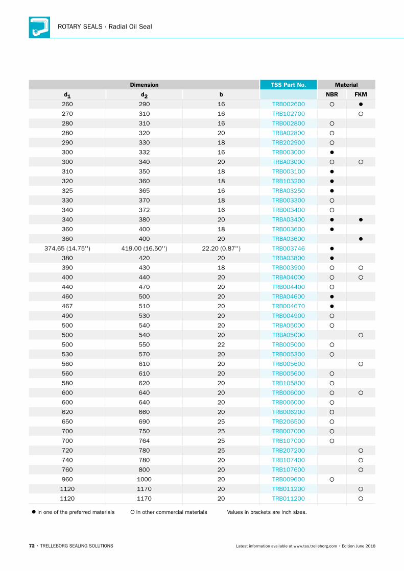
ROTARY SEALS · Radial Oil Seal
72 • TRELLEBORG SEALING SOLUTIONS Latest information available at www.tss.trelleborg.com • Edition June 2018
Dimension TSS Part No. Material
d1 d2 b NBR FKM
260 290 16 TRB002600
270 310 16 TRB102700
280 310 16 TRB002800
280 320 20 TRBA02800
290 330 18 TRB202900
300 332 16 TRB003000
300 340 20 TRBA03000
310 350 18 TRB003100
320 360 18 TRB103200
325 365 16 TRBA03250
330 370 18 TRB003300
340 372 16 TRB003400
340 380 20 TRBA03400
360 400 18 TRB003600
360 400 20 TRBA03600
374.65 (14.75'') 419.00 (16.50'') 22.20 (0.87'') TRB003746
380 420 20 TRBA03800
390 430 18 TRB003900
400 440 20 TRBA04000
440 470 20 TRB004400
460 500 20 TRBA04600
467 510 20 TRB004670
490 530 20 TRB004900
500 540 20 TRBA05000
500 540 20 TRBA05000
500 550 22 TRB005000
530 570 20 TRB005300
560 610 20 TRB005600
560 610 20 TRB005600
580 620 20 TRB105800
600 640 20 TRB006000
600 640 20 TRB006000
620 660 20 TRB006200
650 690 25 TRB206500
700 750 25 TRB007000
700 764 25 TRB107000
720 780 25 TRB207200
740 780 20 TRB107400
760 800 20 TRB107600
960 1000 20 TRB009600
1120 1170 20 TRB011200
1120 1170 20 TRB011200
In one of the preferred materials In other commercial materials Values in brackets are inch sizes.
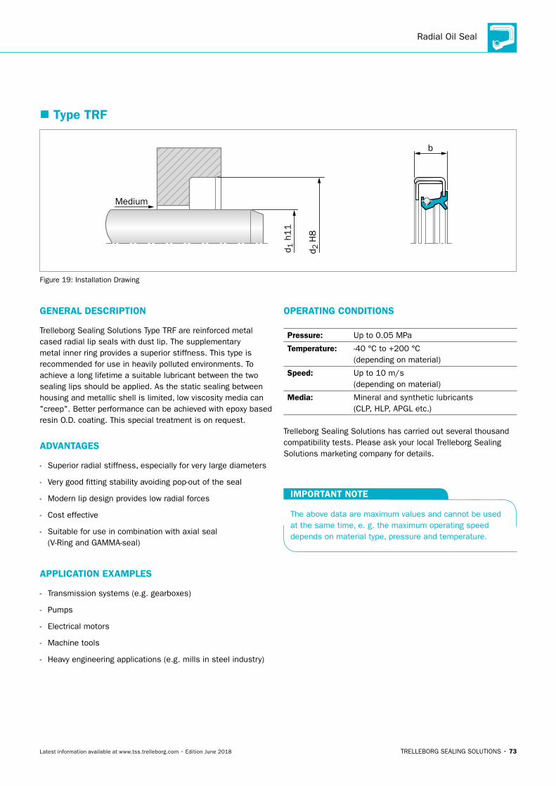
Radial Oil Seal
TRELLEBORG SEALING SOLUTIONS • 73Latest information available at www.tss.trelleborg.com • Edition June 2018
� Type TRF
b
Medium
d 2 H
8
d 1 h
11
Figure 19: Installation Drawing
GENERAL DESCRIPTION
Trelleborg Sealing Solutions Type TRF are reinforced metal cased radial lip seals with dust lip. The supplementary metal inner ring provides a superior stiffness. This type is recommended for use in heavily polluted environments. To achieve a long lifetime a suitable lubricant between the two sealing lips should be applied. As the static sealing between housing and metallic shell is limited, low viscosity media can "creep". Better performance can be achieved with epoxy based resin O.D. coating. This special treatment is on request.
ADVANTAGES
- Superior radial stiffness, especially for very large diameters
- Very good fitting stability avoiding pop-out of the seal
- Modern lip design provides low radial forces
- Cost effective
- Suitable for use in combination with axial seal (V-Ring and GAMMA-seal)
APPLICATION EXAMPLES
- Transmission systems (e.g. gearboxes)
- Pumps
- Electrical motors
- Machine tools
- Heavy engineering applications (e.g. mills in steel industry)
OPERATING CONDITIONS
Pressure: Up to 0.05 MPa
Temperature: -40 °C to +200 °C (depending on material)
Speed: Up to 10 m/s (depending on material)
Media: Mineral and synthetic lubricants (CLP, HLP, APGL etc.)
Trelleborg Sealing Solutions has carried out several thousand compatibility tests. Please ask your local Trelleborg Sealing Solutions marketing company for details.
IMPORTANT NOTE
The above data are maximum values and cannot be used at the same time, e. g. the maximum operating speed depends on material type, pressure and temperature.
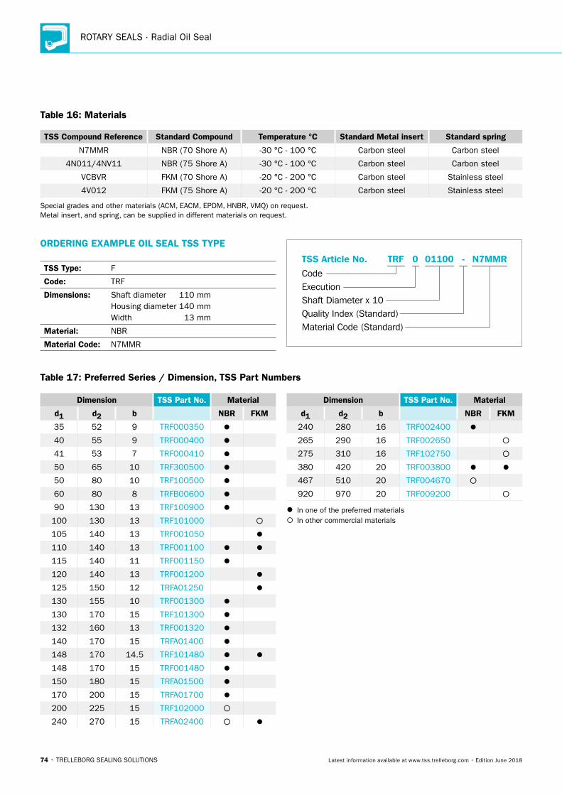
ROTARY SEALS · Radial Oil Seal
74 • TRELLEBORG SEALING SOLUTIONS Latest information available at www.tss.trelleborg.com • Edition June 2018
Table 16: Materials
TSS Compound Reference Standard Compound Temperature °C Standard Metal insert Standard spring
N7MMR NBR (70 Shore A) -30 °C - 100 °C Carbon steel Carbon steel
4N011/4NV11 NBR (75 Shore A) -30 °C - 100 °C Carbon steel Carbon steel
VCBVR FKM (70 Shore A) -20 °C - 200 °C Carbon steel Stainless steel
4V012 FKM (75 Shore A) -20 °C - 200 °C Carbon steel Stainless steel
Special grades and other materials (ACM, EACM, EPDM, HNBR, VMQ) on request. Metal insert, and spring, can be supplied in different materials on request.
ORDERING EXAMPLE OIL SEAL TSS TYPE
TSS Type: F
Code: TRF
Dimensions: Shaft diameter 110 mm Housing diameter 140 mm Width 13 mm
Material: NBR
Material Code: N7MMR
Material Code (Standard)
Code
TSS Article No. -
Shaft Diameter x 10Quality Index (Standard)
TRF
Execution
011000 N7MMR
Table 17: Preferred Series / Dimension, TSS Part Numbers
Dimension TSS Part No. Material
d1 d2 b NBR FKM
35 52 9 TRF000350
40 55 9 TRF000400
41 53 7 TRF000410
50 65 10 TRF300500
50 80 10 TRF100500
60 80 8 TRFB00600
90 130 13 TRF100900
100 130 13 TRF101000
105 140 13 TRF001050
110 140 13 TRF001100
115 140 11 TRF001150
120 140 13 TRF001200
125 150 12 TRFA01250
130 155 10 TRF001300
130 170 15 TRF101300
132 160 13 TRF001320
140 170 15 TRFA01400
148 170 14.5 TRF101480
148 170 15 TRF001480
150 180 15 TRFA01500
170 200 15 TRFA01700
200 225 15 TRF102000
240 270 15 TRFA02400
Dimension TSS Part No. Material
d1 d2 b NBR FKM
240 280 16 TRF002400
265 290 16 TRF002650
275 310 16 TRF102750
380 420 20 TRF003800
467 510 20 TRF004670
920 970 20 TRF009200
In one of the preferred materials In other commercial materials
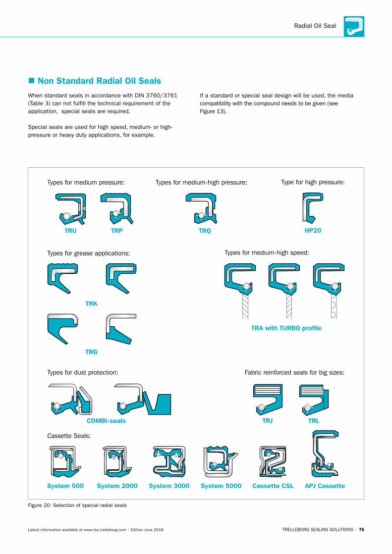
Radial Oil Seal
TRELLEBORG SEALING SOLUTIONS • 75Latest information available at www.tss.trelleborg.com • Edition June 2018
� Non Standard Radial Oil SealsWhen standard seals in accordance with DIN 3760/3761 (Table 3) can not fulfill the technical requirement of the application, special seals are required.
Special seals are used for high speed, medium- or high-pressure or heavy duty applications, for example.
If a standard or special seal design will be used, the media compatibility with the compound needs to be given (see Figure 13).
Types for medium-high speed:
TRA with TURBO profile
Types for grease applications:
TRK
TRG
Cassette Seals:
Fabric reinforced seals for big sizes:
System 500 Cassette CSLSystem 3000 System 5000
Types for medium-high pressure:
TRQ
TRJ TRL
Type for high pressure:
HP20
System 2000 APJ Cassette
Types for medium pressure:
TRU TRP
Types for dust protection:
COMBI-seals
Figure 20: Selection of special radial seals
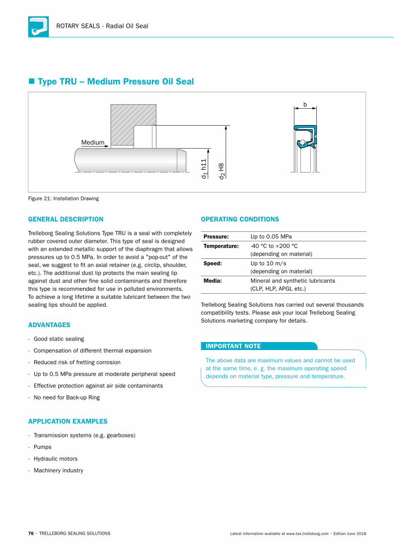
ROTARY SEALS · Radial Oil Seal
76 • TRELLEBORG SEALING SOLUTIONS Latest information available at www.tss.trelleborg.com • Edition June 2018
� Type TRU – Medium Pressure Oil Seal
b
Medium
d 2 H
8
d 1 h
11
Figure 21: Installation Drawing
GENERAL DESCRIPTION
Trelleborg Sealing Solutions Type TRU is a seal with completely rubber covered outer diameter. This type of seal is designed with an extended metallic support of the diaphragm that allows pressures up to 0.5 MPa. In order to avoid a "pop-out" of the seal, we suggest to fit an axial retainer (e.g. circlip, shoulder, etc.). The additional dust lip protects the main sealing lip against dust and other fine solid contaminants and therefore this type is recommended for use in polluted environments. To achieve a long lifetime a suitable lubricant between the two sealing lips should be applied.
ADVANTAGES
- Good static sealing
- Compensation of different thermal expansion
- Reduced risk of fretting corrosion
- Up to 0.5 MPa pressure at moderate peripheral speed
- Effective protection against air side contaminants
- No need for Back-up Ring
APPLICATION EXAMPLES
- Transmission systems (e.g. gearboxes)
- Pumps
- Hydraulic motors
- Machinery industry
OPERATING CONDITIONS
Pressure: Up to 0.05 MPa
Temperature: -40 °C to +200 °C (depending on material)
Speed: Up to 10 m/s (depending on material)
Media: Mineral and synthetic lubricants (CLP, HLP, APGL etc.)
Trelleborg Sealing Solutions has carried out several thousands compatibility tests. Please ask your local Trelleborg Sealing Solutions marketing company for details.
IMPORTANT NOTE
The above data are maximum values and cannot be used at the same time, e. g. the maximum operating speed depends on material type, pressure and temperature.
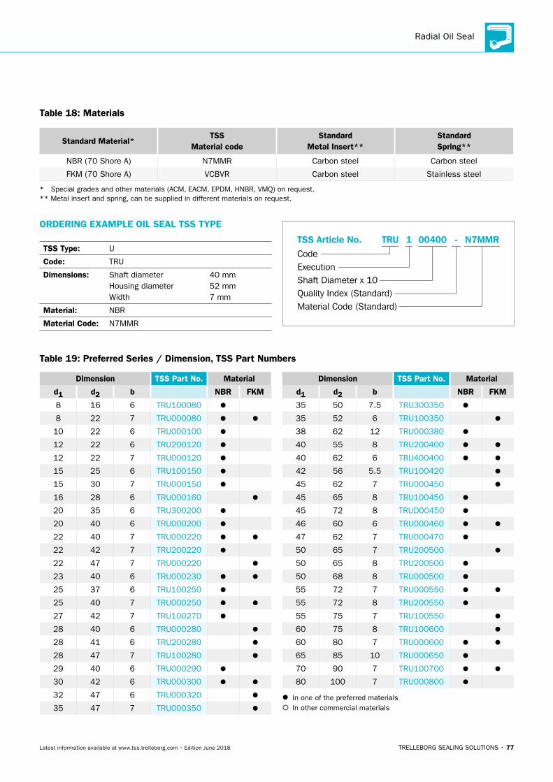
Radial Oil Seal
TRELLEBORG SEALING SOLUTIONS • 77Latest information available at www.tss.trelleborg.com • Edition June 2018
Table 18: Materials
Standard Material*TSS
Material codeStandard
Metal Insert**Standard Spring**
NBR (70 Shore A) N7MMR Carbon steel Carbon steel
FKM (70 Shore A) VCBVR Carbon steel Stainless steel
* Special grades and other materials (ACM, EACM, EPDM, HNBR, VMQ) on request. ** Metal insert and spring, can be supplied in different materials on request.
ORDERING EXAMPLE OIL SEAL TSS TYPE
TSS Type: U
Code: TRU
Dimensions: Shaft diameter 40 mm Housing diameter 52 mm Width 7 mm
Material: NBR
Material Code: N7MMR
Material Code (Standard)
Code
TSS Article No. -
Shaft Diameter x 10Quality Index (Standard)
TRU
Execution
004001 N7MMR
Dimension TSS Part No. Material
d1 d2 b NBR FKM
8 16 6 TRU100080
8 22 7 TRU000080
10 22 6 TRU000100
12 22 6 TRU200120
12 22 7 TRU000120
15 25 6 TRU100150
15 30 7 TRU000150
16 28 6 TRU000160
20 35 6 TRU300200
20 40 6 TRU000200
22 40 7 TRU000220
22 42 7 TRU200220
22 47 7 TRU000220
23 40 6 TRU000230
25 37 6 TRU100250
25 40 7 TRU000250
27 42 7 TRU100270
28 40 6 TRU000280
28 41 6 TRU200280
28 47 7 TRU100280
29 40 6 TRU000290
30 42 6 TRU000300
32 47 6 TRU000320
35 47 7 TRU000350
Dimension TSS Part No. Material
d1 d2 b NBR FKM
35 50 7.5 TRU300350
35 52 6 TRU100350
38 62 12 TRU000380
40 55 8 TRU200400
40 62 6 TRU400400
42 56 5.5 TRU100420
45 62 7 TRU000450
45 65 8 TRU100450
45 72 8 TRUD00450
46 60 6 TRU000460
47 62 7 TRU000470
50 65 7 TRU200500
50 65 8 TRU200500
50 68 8 TRU000500
55 72 7 TRU000550
55 72 8 TRU200550
55 75 7 TRU100550
60 75 8 TRU100600
60 80 7 TRU000600
65 85 10 TRU000650
70 90 7 TRU100700
80 100 7 TRU000800
In one of the preferred materials In other commercial materials
Table 19: Preferred Series / Dimension, TSS Part Numbers
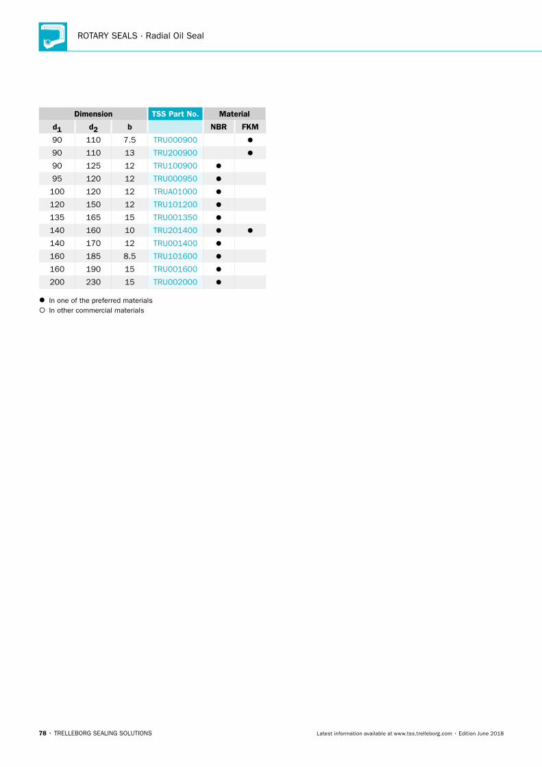
ROTARY SEALS · Radial Oil Seal
78 • TRELLEBORG SEALING SOLUTIONS Latest information available at www.tss.trelleborg.com • Edition June 2018
Dimension TSS Part No. Material
d1 d2 b NBR FKM
90 110 7.5 TRU000900
90 110 13 TRU200900
90 125 12 TRU100900
95 120 12 TRU000950
100 120 12 TRUA01000
120 150 12 TRU101200
135 165 15 TRU001350
140 160 10 TRU201400
140 170 12 TRU001400
160 185 8.5 TRU101600
160 190 15 TRU001600
200 230 15 TRU002000
In one of the preferred materials In other commercial materials
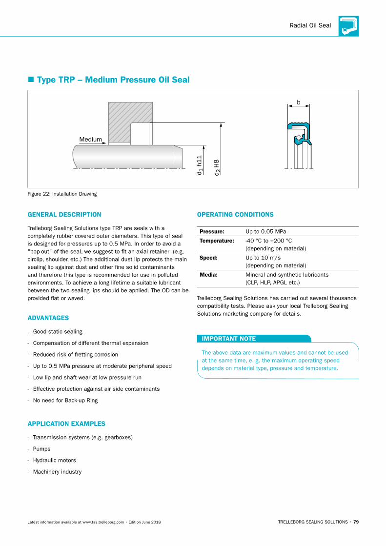
Radial Oil Seal
TRELLEBORG SEALING SOLUTIONS • 79Latest information available at www.tss.trelleborg.com • Edition June 2018
� Type TRP – Medium Pressure Oil Seal
b
Medium
d 2 H
8
d 1 h
11
Figure 22: Installation Drawing
GENERAL DESCRIPTION
Trelleborg Sealing Solutions type TRP are seals with a completely rubber covered outer diameters. This type of seal is designed for pressures up to 0.5 MPa. In order to avoid a "pop-out" of the seal, we suggest to fit an axial retainer (e.g. circlip, shoulder, etc.) The additional dust lip protects the main sealing lip against dust and other fine solid contaminants and therefore this type is recommended for use in polluted environments. To achieve a long lifetime a suitable lubricant between the two sealing lips should be applied. The OD can be provided flat or waved.
ADVANTAGES
- Good static sealing
- Compensation of different thermal expansion
- Reduced risk of fretting corrosion
- Up to 0.5 MPa pressure at moderate peripheral speed
- Low lip and shaft wear at low pressure run
- Effective protection against air side contaminants
- No need for Back-up Ring
APPLICATION EXAMPLES
- Transmission systems (e.g. gearboxes)
- Pumps
- Hydraulic motors
- Machinery industry
OPERATING CONDITIONS
Pressure: Up to 0.05 MPa
Temperature: -40 °C to +200 °C (depending on material)
Speed: Up to 10 m/s (depending on material)
Media: Mineral and synthetic lubricants (CLP, HLP, APGL etc.)
Trelleborg Sealing Solutions has carried out several thousands compatibility tests. Please ask your local Trelleborg Sealing Solutions marketing company for details.
IMPORTANT NOTE
The above data are maximum values and cannot be used at the same time, e. g. the maximum operating speed depends on material type, pressure and temperature.
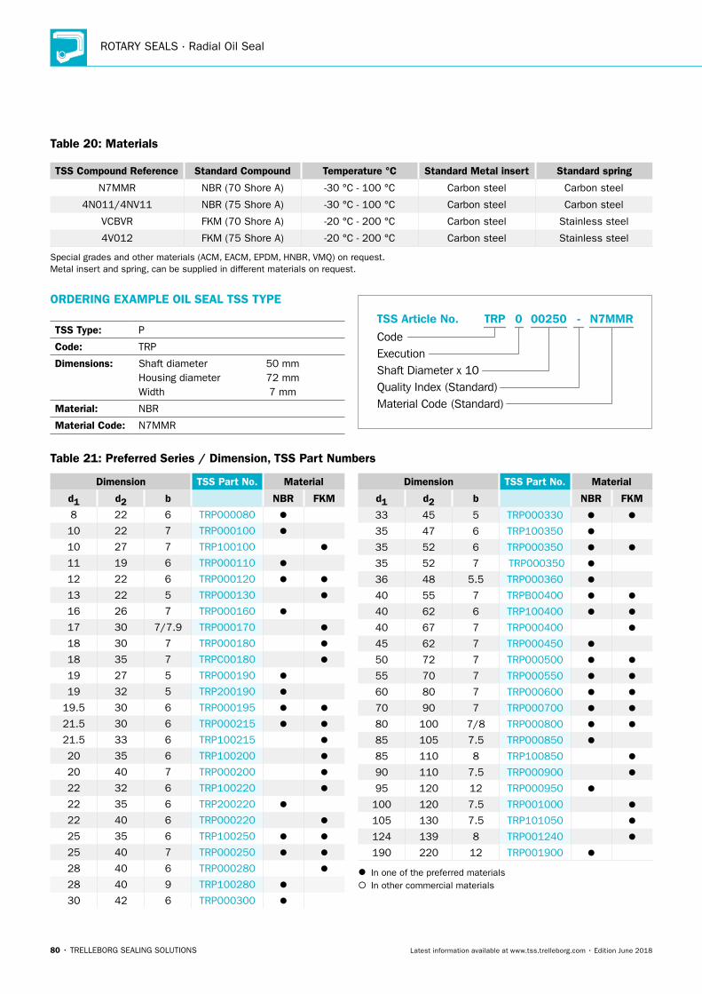
ROTARY SEALS · Radial Oil Seal
80 • TRELLEBORG SEALING SOLUTIONS Latest information available at www.tss.trelleborg.com • Edition June 2018
Table 20: Materials
TSS Compound Reference Standard Compound Temperature °C Standard Metal insert Standard spring
N7MMR NBR (70 Shore A) -30 °C - 100 °C Carbon steel Carbon steel
4N011/4NV11 NBR (75 Shore A) -30 °C - 100 °C Carbon steel Carbon steel
VCBVR FKM (70 Shore A) -20 °C - 200 °C Carbon steel Stainless steel
4V012 FKM (75 Shore A) -20 °C - 200 °C Carbon steel Stainless steel
Special grades and other materials (ACM, EACM, EPDM, HNBR, VMQ) on request. Metal insert and spring, can be supplied in different materials on request.
ORDERING EXAMPLE OIL SEAL TSS TYPE
TSS Type: P
Code: TRP
Dimensions: Shaft diameter 50 mm Housing diameter 72 mm Width 7 mm
Material: NBR
Material Code: N7MMR
Material Code (Standard)
Code
TSS Article No. -
Shaft Diameter x 10Quality Index (Standard)
TRP
Execution
002500 N7MMR
Table 21: Preferred Series / Dimension, TSS Part Numbers
Dimension TSS Part No. Material
d1 d2 b NBR FKM
8 22 6 TRP000080
10 22 7 TRP000100
10 27 7 TRP100100
11 19 6 TRP000110
12 22 6 TRP000120
13 22 5 TRP000130
16 26 7 TRP000160
17 30 7/7.9 TRP000170
18 30 7 TRP000180
18 35 7 TRPC00180
19 27 5 TRP000190
19 32 5 TRP200190
19.5 30 6 TRP000195
21.5 30 6 TRP000215
21.5 33 6 TRP100215
20 35 6 TRP100200
20 40 7 TRP000200
22 32 6 TRP100220
22 35 6 TRP200220
22 40 6 TRP000220
25 35 6 TRP100250
25 40 7 TRP000250
28 40 6 TRP000280
28 40 9 TRP100280
30 42 6 TRP000300
Dimension TSS Part No. Material
d1 d2 b NBR FKM
33 45 5 TRP000330
35 47 6 TRP100350
35 52 6 TRP000350
35 52 7 TRP000350
36 48 5.5 TRP000360
40 55 7 TRPB00400
40 62 6 TRP100400
40 67 7 TRP000400
45 62 7 TRP000450
50 72 7 TRP000500
55 70 7 TRP000550
60 80 7 TRP000600
70 90 7 TRP000700
80 100 7/8 TRP000800
85 105 7.5 TRP000850
85 110 8 TRP100850
90 110 7.5 TRP000900
95 120 12 TRP000950
100 120 7.5 TRP001000
105 130 7.5 TRP101050
124 139 8 TRP001240
190 220 12 TRP001900
In one of the preferred materials In other commercial materials
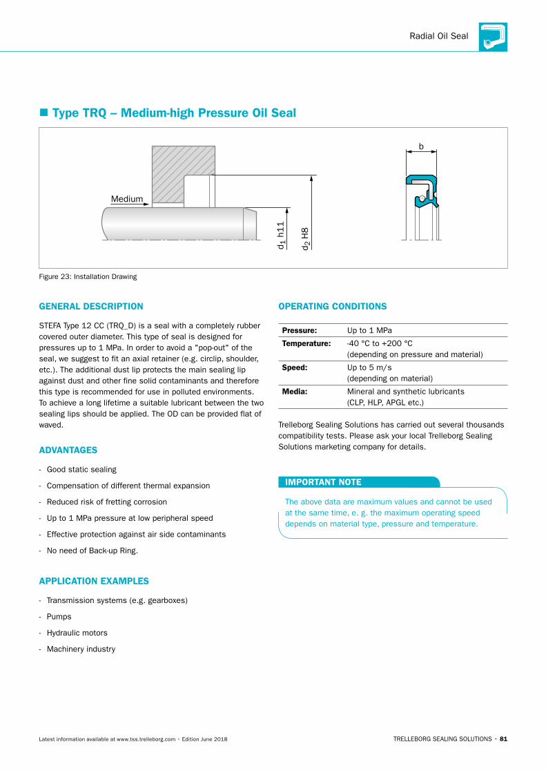
Radial Oil Seal
TRELLEBORG SEALING SOLUTIONS • 81Latest information available at www.tss.trelleborg.com • Edition June 2018
� Type TRQ – Medium-high Pressure Oil Seal
b
Medium
d 2 H
8
d 1 h
11
Figure 23: Installation Drawing
GENERAL DESCRIPTION
STEFA Type 12 CC (TRQ_D) is a seal with a completely rubber covered outer diameter. This type of seal is designed for pressures up to 1 MPa. In order to avoid a "pop-out" of the seal, we suggest to fit an axial retainer (e.g. circlip, shoulder, etc.). The additional dust lip protects the main sealing lip against dust and other fine solid contaminants and therefore this type is recommended for use in polluted environments. To achieve a long lifetime a suitable lubricant between the two sealing lips should be applied. The OD can be provided flat of waved.
ADVANTAGES
- Good static sealing
- Compensation of different thermal expansion
- Reduced risk of fretting corrosion
- Up to 1 MPa pressure at low peripheral speed
- Effective protection against air side contaminants
- No need of Back-up Ring.
APPLICATION EXAMPLES
- Transmission systems (e.g. gearboxes)
- Pumps
- Hydraulic motors
- Machinery industry
OPERATING CONDITIONS
Pressure: Up to 1 MPa
Temperature: -40 °C to +200 °C (depending on pressure and material)
Speed: Up to 5 m/s (depending on material)
Media: Mineral and synthetic lubricants (CLP, HLP, APGL etc.)
Trelleborg Sealing Solutions has carried out several thousands compatibility tests. Please ask your local Trelleborg Sealing Solutions marketing company for details.
IMPORTANT NOTE
The above data are maximum values and cannot be used at the same time, e. g. the maximum operating speed depends on material type, pressure and temperature.
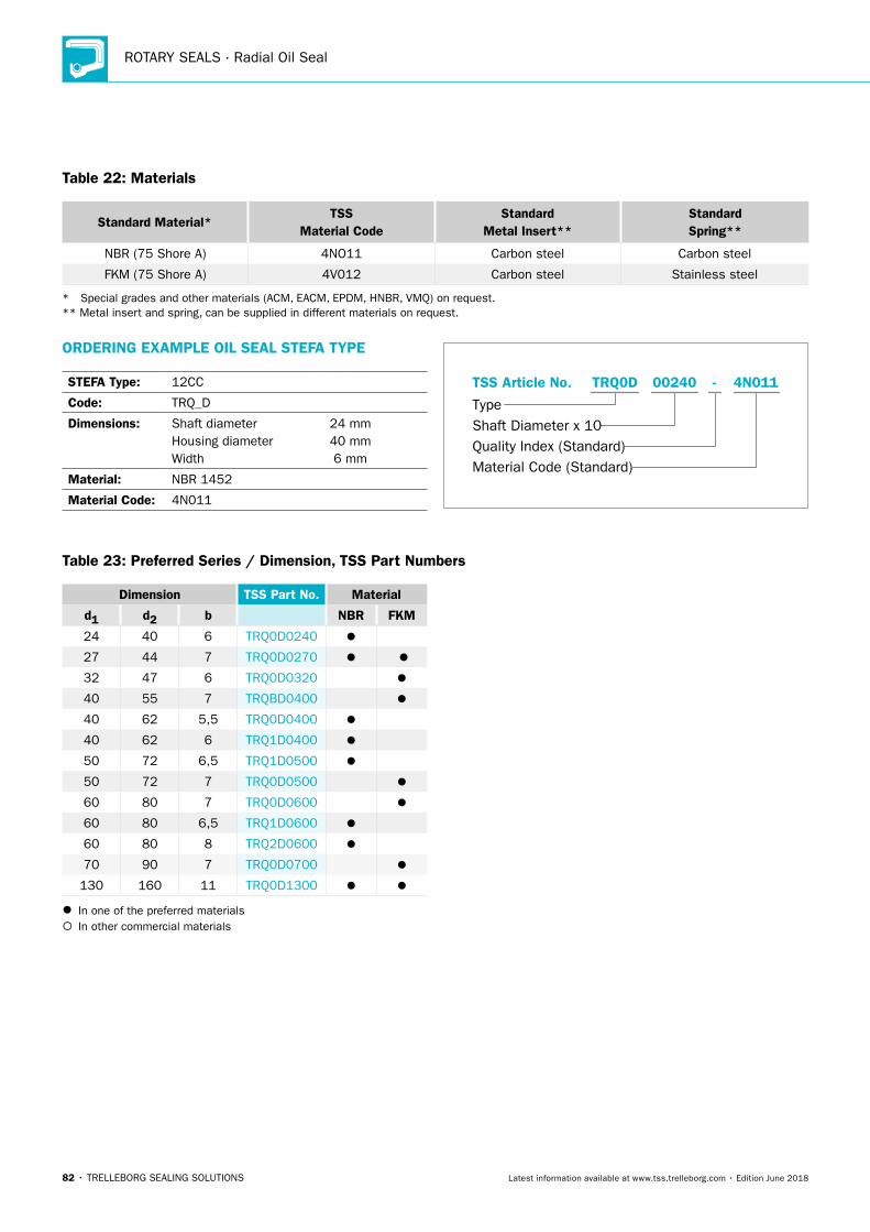
ROTARY SEALS · Radial Oil Seal
82 • TRELLEBORG SEALING SOLUTIONS Latest information available at www.tss.trelleborg.com • Edition June 2018
Table 22: Materials
Standard Material*TSS
Material CodeStandard
Metal Insert**Standard Spring**
NBR (75 Shore A) 4NO11 Carbon steel Carbon steel
FKM (75 Shore A) 4V012 Carbon steel Stainless steel
* Special grades and other materials (ACM, EACM, EPDM, HNBR, VMQ) on request. ** Metal insert and spring, can be supplied in different materials on request.
ORDERING EXAMPLE OIL SEAL STEFA TYPE
STEFA Type: 12CC
Code: TRQ_D
Dimensions: Shaft diameter 24 mm Housing diameter 40 mm Width 6 mm
Material: NBR 1452
Material Code: 4N011
Material Code (Standard)
Type
TSS Article No. 4N01100240 -
Shaft Diameter x 10Quality Index (Standard)
TRQ0D
Table 23: Preferred Series / Dimension, TSS Part Numbers
Dimension TSS Part No. Material
d1 d2 b NBR FKM
24 40 6 TRQ0D0240
27 44 7 TRQ0D0270
32 47 6 TRQ0D0320
40 55 7 TRQBD0400
40 62 5,5 TRQ0D0400
40 62 6 TRQ1D0400
50 72 6,5 TRQ1D0500
50 72 7 TRQ0D0500
60 80 7 TRQ0D0600
60 80 6,5 TRQ1D0600
60 80 8 TRQ2D0600
70 90 7 TRQ0D0700
130 160 11 TRQ0D1300
In one of the preferred materials In other commercial materials
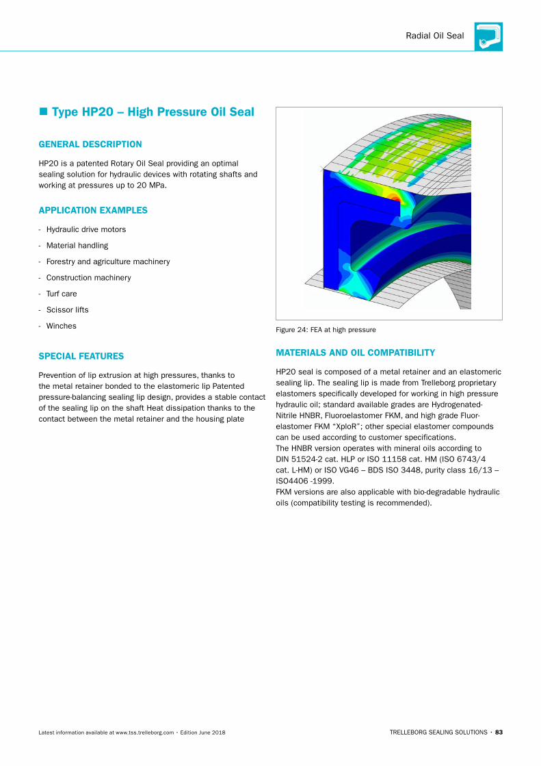
Radial Oil Seal
TRELLEBORG SEALING SOLUTIONS • 83Latest information available at www.tss.trelleborg.com • Edition June 2018
� Type HP20 – High Pressure Oil Seal
GENERAL DESCRIPTION
HP20 is a patented Rotary Oil Seal providing an optimal sealing solution for hydraulic devices with rotating shafts and working at pressures up to 20 MPa.
APPLICATION EXAMPLES
- Hydraulic drive motors
- Material handling
- Forestry and agriculture machinery
- Construction machinery
- Turf care
- Scissor lifts
- Winches
SPECIAL FEATURES
Prevention of lip extrusion at high pressures, thanks to the metal retainer bonded to the elastomeric lip Patented pressure-balancing sealing lip design, provides a stable contact of the sealing lip on the shaft Heat dissipation thanks to the contact between the metal retainer and the housing plate
Figure 24: FEA at high pressure
MATERIALS AND OIL COMPATIBILITY
HP20 seal is composed of a metal retainer and an elastomeric sealing lip. The sealing lip is made from Trelleborg proprietary elastomers specifically developed for working in high pressure hydraulic oil; standard available grades are Hydrogenated-Nitrile HNBR, Fluoroelastomer FKM, and high grade Fluor-elastomer FKM “XploR”; other special elastomer compounds can be used according to customer specifications.The HNBR version operates with mineral oils according to DIN 51524-2 cat. HLP or ISO 11158 cat. HM (ISO 6743/4 cat. L-HM) or ISO VG46 – BDS ISO 3448, purity class 16/13 – ISO4406 -1999.FKM versions are also applicable with bio-degradable hydraulic oils (compatibility testing is recommended).
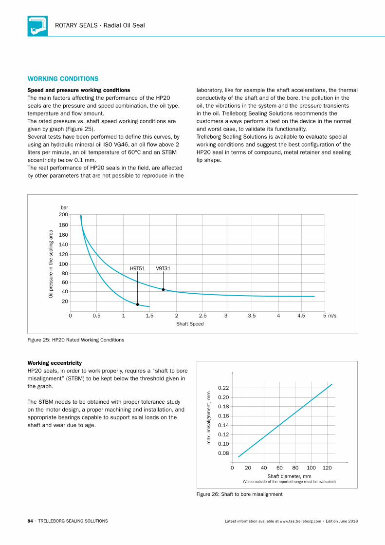
ROTARY SEALS · Radial Oil Seal
84 • TRELLEBORG SEALING SOLUTIONS Latest information available at www.tss.trelleborg.com • Edition June 2018
WORKING CONDITIONS
0
bar
20
40
60
80
100
120
140
160
180
200
0.5 1 1.5 2 2.5 3 3.5 4 4.5 5
Shaft Speed
m/s
Oil
pres
sure
in t
he s
ealin
g ar
ea
V9T31H9T51
Figure 25: HP20 Rated Working Conditions
Speed and pressure working conditionsThe main factors affecting the performance of the HP20 seals are the pressure and speed combination, the oil type, temperature and flow amount.The rated pressure vs. shaft speed working conditions are given by graph (Figure 25).Several tests have been performed to define this curves, by using an hydraulic mineral oil ISO VG46, an oil flow above 2 liters per minute, an oil temperature of 60°C and an STBM eccentricity below 0.1 mm.The real performance of HP20 seals in the field, are affected by other parameters that are not possible to reproduce in the
laboratory, like for example the shaft accelerations, the thermal conductivity of the shaft and of the bore, the pollution in the oil, the vibrations in the system and the pressure transients in the oil. Trelleborg Sealing Solutions recommends the customers always perform a test on the device in the normal and worst case, to validate its functionality.Trelleborg Sealing Solutions is available to evaluate special working conditions and suggest the best configuration of the HP20 seal in terms of compound, metal retainer and sealing lip shape.
Working eccentricityHP20 seals, in order to work properly, requires a “shaft to boremisalignment” (STBM) to be kept below the threshold given in the graph.
The STBM needs to be obtained with proper tolerance study on the motor design, a proper machining and installation, and appropriate bearings capable to support axial loads on the shaft and wear due to age.
20 40 60 80 100 1200
0.08
0.10
0.12
0.14
0.16
0.18
0.20
0.22
Shaft diameter, mm(Value outside of the reported range must be evaluated)
max
. mis
alig
nmen
t, m
m
Figure 26: Shaft to bore misalignment
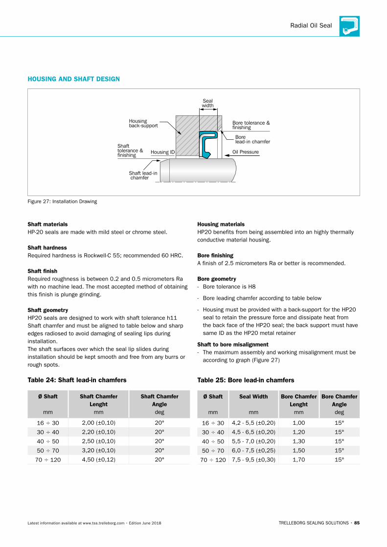
Radial Oil Seal
TRELLEBORG SEALING SOLUTIONS • 85Latest information available at www.tss.trelleborg.com • Edition June 2018
Shaft materialsHP-20 seals are made with mild steel or chrome steel.
Shaft hardnessRequired hardness is Rockwell-C 55; recommended 60 HRC.
Shaft finishRequired roughness is between 0.2 and 0.5 micrometers Ra with no machine lead. The most accepted method of obtainingthis finish is plunge grinding.
Shaft geometryHP20 seals are designed to work with shaft tolerance h11Shaft chamfer and must be aligned to table below and sharp edges radiosed to avoid damaging of sealing lips during installation.The shaft surfaces over which the seal lip slides duringinstallation should be kept smooth and free from any burrs orrough spots.
Table 24: Shaft lead-in chamfers
Ø Shaft
mm
Shaft Chamfer Lenght
mm
Shaft Chamfer Angle deg
16 30 2,00 (±0,10) 20°
30 40 2,20 (±0,10) 20°
40 50 2,50 (±0,10) 20°
50 70 3,20 (±0,10) 20°
70 120 4,50 (±0,12) 20°
Housing materialsHP20 benefits from being assembled into an highly thermally conductive material housing.
Bore finishingA finish of 2.5 micrometers Ra or better is recommended.
Bore geometry - Bore tolerance is H8
- Bore leading chamfer according to table below
- Housing must be provided with a back-support for the HP20 seal to retain the pressure force and dissipate heat from the back face of the HP20 seal; the back support must have same ID as the HP20 metal retainer
Shaft to bore misalignment - The maximum assembly and working misalignment must be
according to graph (Figure 27)
Table 25: Bore lead-in chamfers
Ø Shaft
mm
Seal Width
mm
Bore Chamfer Lenght
mm
Bore Chamfer Angledeg
16 30 4,2 - 5,5 (±0,20) 1,00 15°
30 40 4,5 - 6,5 (±0,20) 1,20 15°
40 50 5,5 - 7,0 (±0,20) 1,30 15°
50 70 6,0 - 7,5 (±0,25) 1,50 15°
70 120 7,5 - 9,5 (±0,30) 1,70 15°
HOUSING AND SHAFT DESIGN
Shaft tolerance &finishing Housing ID
Bore tolerance &finishing
Sealwidth
Shaft lead-in chamfer
Bore lead-in chamfer
Housingback-support
Oil Pressure
Figure 27: Installation Drawing
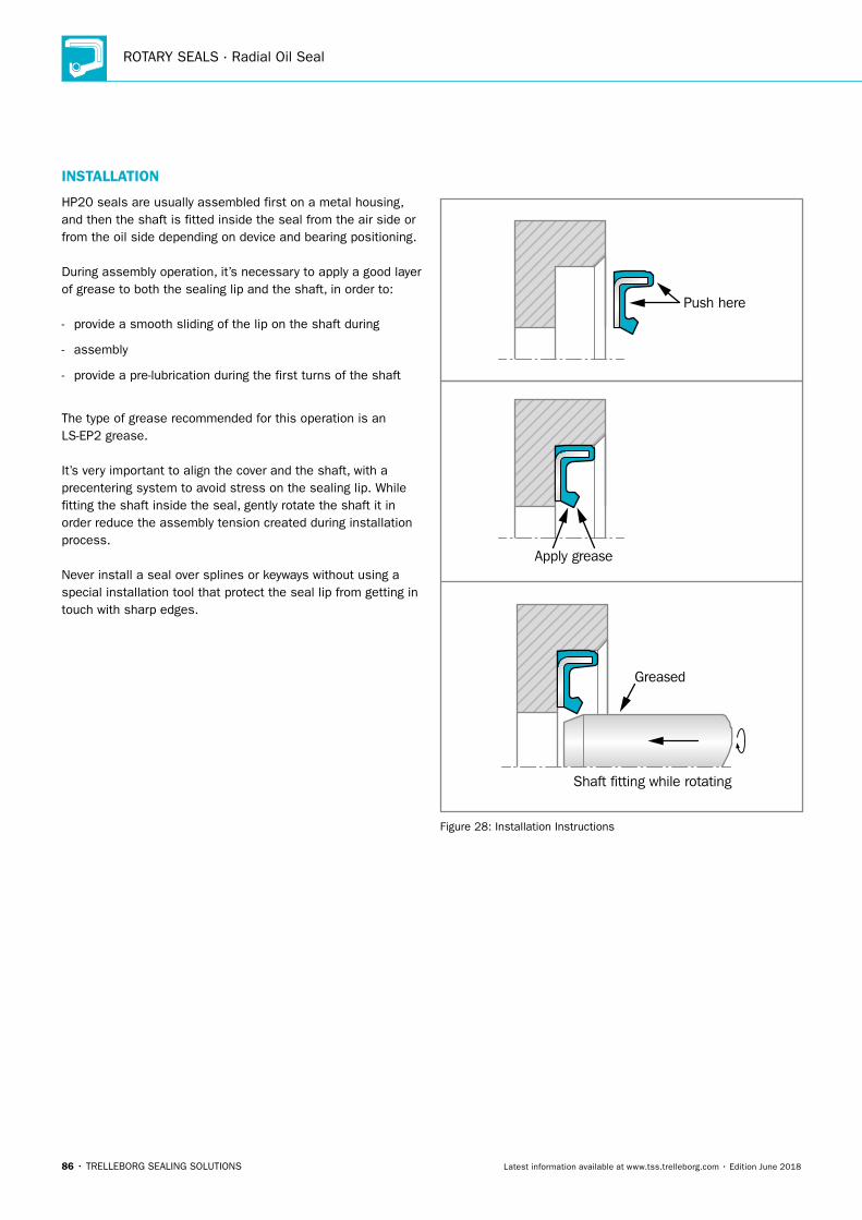
ROTARY SEALS · Radial Oil Seal
86 • TRELLEBORG SEALING SOLUTIONS Latest information available at www.tss.trelleborg.com • Edition June 2018
INSTALLATION
HP20 seals are usually assembled first on a metal housing, and then the shaft is fitted inside the seal from the air side or from the oil side depending on device and bearing positioning.
During assembly operation, it’s necessary to apply a good layer of grease to both the sealing lip and the shaft, in order to:
- provide a smooth sliding of the lip on the shaft during
- assembly
- provide a pre-lubrication during the first turns of the shaft
The type of grease recommended for this operation is an LS-EP2 grease.
It’s very important to align the cover and the shaft, with a precentering system to avoid stress on the sealing lip. While fitting the shaft inside the seal, gently rotate the shaft it in order reduce the assembly tension created during installation process.
Never install a seal over splines or keyways without using a special installation tool that protect the seal lip from getting in touch with sharp edges.
Push here
Apply grease
Greased
Shaft fitting while rotating
Figure 28: Installation Instructions
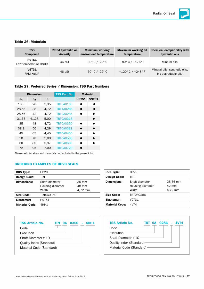
Radial Oil Seal
TRELLEBORG SEALING SOLUTIONS • 87Latest information available at www.tss.trelleborg.com • Edition June 2018
Table 26: Materials
TSS Compound
Rated hydraulic oil viscosity
Minimum working enviroment temperature
Maximum working oiltemperature
Chemical compatibility with hydraulic oils
H9T51 Low temperature HNBR
46 cSt -30° C / -22° C +80° C / +176° F Mineral oils
V9T31 FKM XploR
46 cSt -30° C / -22° C +120° C / +248° FMineral oils, synthetic oils,
bio-degradable oils
Table 27: Preferred Series / Dimension, TSS Part Numbers
Dimension TSS Part No. Material
d1 d2 b H9T51 V9T31
16,9 28 5,35 TRT0A0169
28,56 38 4,72 TRT1A0286
28,56 42 4,72 TRT0A0286
31,75 41,28 5,00 TRT0A0318
35 48 4,72 TRT0A0350
38,1 50 4,29 TRT0A0381
45 65 4,45 TRT0A0450
50 70 5,08 TRT0A0500
60 80 5,97 TRT0A0600
72 95 7,00 TRT0A0720
Please ask for sizes and materials not included in the present list.
ORDERING EXAMPLES OF HP20 SEALS
ROS Type: HP20
Design Code: TRT
Dimensions: Shaft diameter 35 mm Housing diameter 48 mm Width 4,72 mm
Size Code: TRT0A0350
Elastomer: H9T51
Material Code: 4HH1
ROS Type: HP20
Design Code: TRT
Dimensions: Shaft diameter 28,56 mm Housing diameter 42 mm Width 4,72 mm
Size Code: TRT0A0286
Elastomer: V9T31
Material Code: 4VT4
Material Code (Standard)
Code
TSS Article No. -
Shaft Diameter x 10Quality Index (Standard)
TRT
Execution
03500A 4HH1
Material Code (Standard)
Code
TSS Article No. -
Shaft Diameter x 10Quality Index (Standard)
TRT
Execution
02860A 4VT4
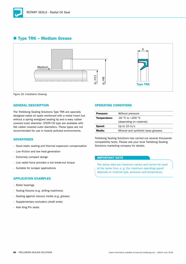
ROTARY SEALS · Radial Oil Seal
88 • TRELLEBORG SEALING SOLUTIONS Latest information available at www.tss.trelleborg.com • Edition June 2018
� Type TRK – Medium Grease
b
Medium
Type TRKd 2 H
8
d 1 h
11
Figure 29: Installation Drawing
GENERAL DESCRIPTION
The Trelleborg Sealing Solutions Type TRK are specially designed radial oil seals reinforced with a metal insert but without a spring energized sealing lip and a wavy rubber covered outer diameter. STEFA CD type are available with flat rubber covered outer diameters. These types are not recommended for use in heavily polluted environments.
ADVANTAGES
- Good static sealing and thermal expansion compensation
- Low friction and low heat generation
- Extremely compact design
- Low radial force provides a low break-out torque
- Suitable for scraper applications
APPLICATION EXAMPLES
- Roller bearings
- Tooling fixtures (e.g. drilling machines)
- Sealing against viscous media (e.g. grease)
- Supplementary excluders (shaft ends)
- Axle King Pin seals
OPERATING CONDITIONS
Pressure: Without pressure
Temperature: -40 °C to +200 °C (depending on material)
Speed: Up to 10 m/s
Media: Mineral and synthetic base greases
Trelleborg Sealing Solutions has carried out several thousands compatibility tests. Please ask your local Trelleborg Sealing Solutions marketing company for details.
IMPORTANT NOTE
The above data are maximum values and cannot be used at the same time, e. g. the maximum operating speed depends on material type, pressure and temperature.
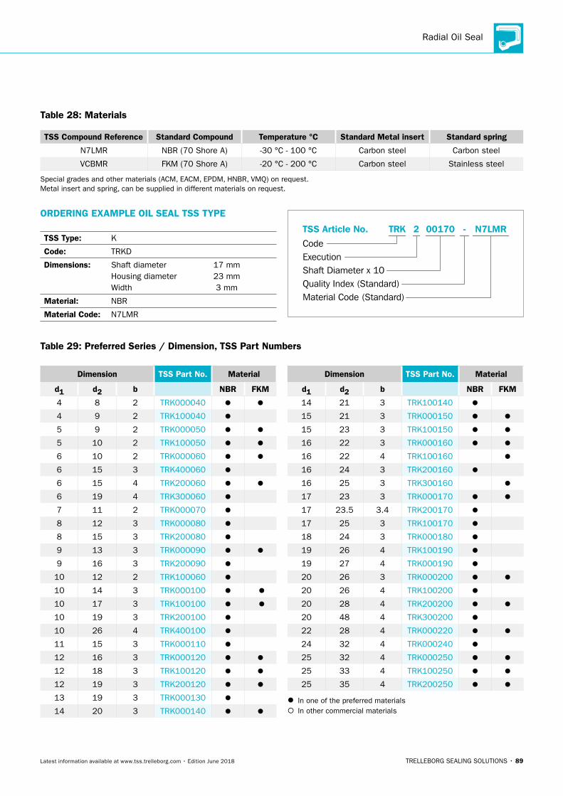
Radial Oil Seal
TRELLEBORG SEALING SOLUTIONS • 89Latest information available at www.tss.trelleborg.com • Edition June 2018
Table 28: Materials
TSS Compound Reference Standard Compound Temperature °C Standard Metal insert Standard spring
N7LMR NBR (70 Shore A) -30 °C - 100 °C Carbon steel Carbon steel
VCBMR FKM (70 Shore A) -20 °C - 200 °C Carbon steel Stainless steel
Special grades and other materials (ACM, EACM, EPDM, HNBR, VMQ) on request. Metal insert and spring, can be supplied in different materials on request.
ORDERING EXAMPLE OIL SEAL TSS TYPE
TSS Type: K
Code: TRKD
Dimensions: Shaft diameter 17 mm Housing diameter 23 mm Width 3 mm
Material: NBR
Material Code: N7LMR
Material Code (Standard)
Code
TSS Article No. -
Shaft Diameter x 10Quality Index (Standard)
TRK
Execution
001702 N7LMR
Table 29: Preferred Series / Dimension, TSS Part Numbers
Dimension TSS Part No. Material
d1 d2 b NBR FKM
4 8 2 TRK000040
4 9 2 TRK100040
5 9 2 TRK000050
5 10 2 TRK100050
6 10 2 TRK000060
6 15 3 TRK400060
6 15 4 TRK200060
6 19 4 TRK300060
7 11 2 TRK000070
8 12 3 TRK000080
8 15 3 TRK200080
9 13 3 TRK000090
9 16 3 TRK200090
10 12 2 TRK100060
10 14 3 TRK000100
10 17 3 TRK100100
10 19 3 TRK200100
10 26 4 TRK400100
11 15 3 TRK000110
12 16 3 TRK000120
12 18 3 TRK100120
12 19 3 TRK200120
13 19 3 TRK000130
14 20 3 TRK000140
Dimension TSS Part No. Material
d1 d2 b NBR FKM
14 21 3 TRK100140
15 21 3 TRK000150
15 23 3 TRK100150
16 22 3 TRK000160
16 22 4 TRK100160
16 24 3 TRK200160
16 25 3 TRK300160
17 23 3 TRK000170
17 23.5 3.4 TRK200170
17 25 3 TRK100170
18 24 3 TRK000180
19 26 4 TRK100190
19 27 4 TRK000190
20 26 3 TRK000200
20 26 4 TRK100200
20 28 4 TRK200200
20 48 4 TRK300200
22 28 4 TRK000220
24 32 4 TRK000240
25 32 4 TRK000250
25 33 4 TRK100250
25 35 4 TRK200250
In one of the preferred materials In other commercial materials
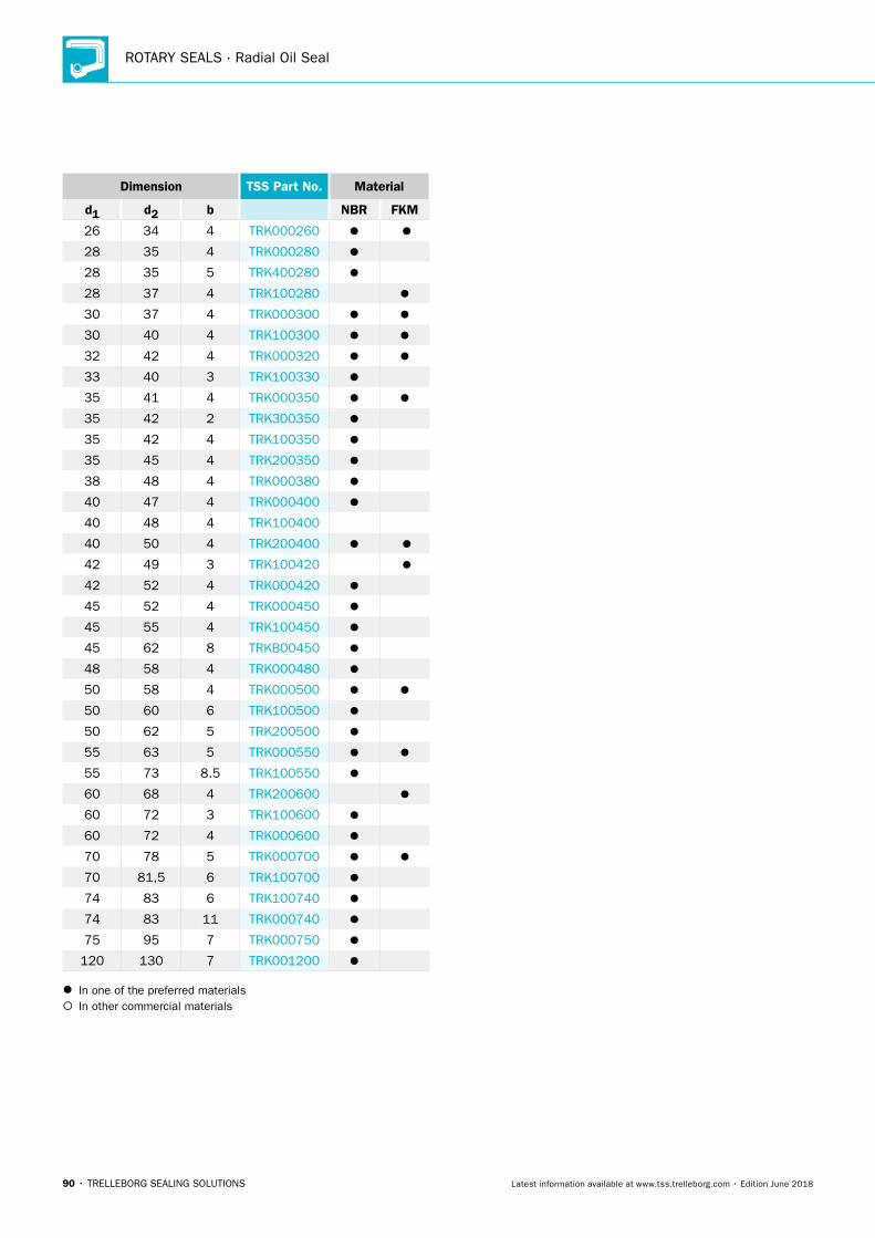
ROTARY SEALS · Radial Oil Seal
90 • TRELLEBORG SEALING SOLUTIONS Latest information available at www.tss.trelleborg.com • Edition June 2018
Dimension TSS Part No. Material
d1 d2 b NBR FKM
26 34 4 TRK000260
28 35 4 TRK000280
28 35 5 TRK400280
28 37 4 TRK100280
30 37 4 TRK000300
30 40 4 TRK100300
32 42 4 TRK000320
33 40 3 TRK100330
35 41 4 TRK000350
35 42 2 TRK300350
35 42 4 TRK100350
35 45 4 TRK200350
38 48 4 TRK000380
40 47 4 TRK000400
40 48 4 TRK100400
40 50 4 TRK200400
42 49 3 TRK100420
42 52 4 TRK000420
45 52 4 TRK000450
45 55 4 TRK100450
45 62 8 TRKB00450
48 58 4 TRK000480
50 58 4 TRK000500
50 60 6 TRK100500
50 62 5 TRK200500
55 63 5 TRK000550
55 73 8.5 TRK100550
60 68 4 TRK200600
60 72 3 TRK100600
60 72 4 TRK000600
70 78 5 TRK000700
70 81,5 6 TRK100700
74 83 6 TRK100740
74 83 11 TRK000740
75 95 7 TRK000750
120 130 7 TRK001200
In one of the preferred materials In other commercial materials
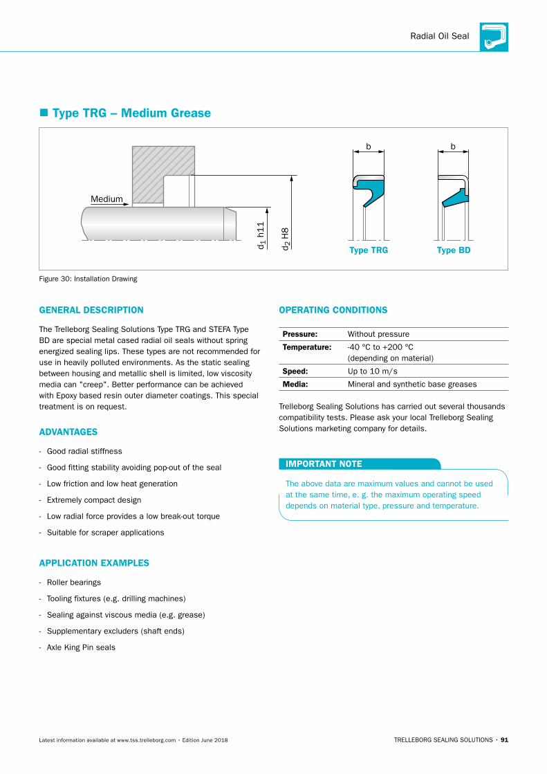
Radial Oil Seal
TRELLEBORG SEALING SOLUTIONS • 91Latest information available at www.tss.trelleborg.com • Edition June 2018
� Type TRG – Medium Grease
b b
Medium
Type TRG Type BDd 2 H
8
d 1 h
11
Figure 30: Installation Drawing
GENERAL DESCRIPTION
The Trelleborg Sealing Solutions Type TRG and STEFA Type BD are special metal cased radial oil seals without spring energized sealing lips. These types are not recommended for use in heavily polluted environments. As the static sealing between housing and metallic shell is limited, low viscosity media can "creep". Better performance can be achieved with Epoxy based resin outer diameter coatings. This special treatment is on request.
ADVANTAGES
- Good radial stiffness
- Good fitting stability avoiding pop-out of the seal
- Low friction and low heat generation
- Extremely compact design
- Low radial force provides a low break-out torque
- Suitable for scraper applications
APPLICATION EXAMPLES
- Roller bearings
- Tooling fixtures (e.g. drilling machines)
- Sealing against viscous media (e.g. grease)
- Supplementary excluders (shaft ends)
- Axle King Pin seals
OPERATING CONDITIONS
Pressure: Without pressure
Temperature: -40 °C to +200 °C (depending on material)
Speed: Up to 10 m/s
Media: Mineral and synthetic base greases
Trelleborg Sealing Solutions has carried out several thousands compatibility tests. Please ask your local Trelleborg Sealing Solutions marketing company for details.
IMPORTANT NOTE
The above data are maximum values and cannot be used at the same time, e. g. the maximum operating speed depends on material type, pressure and temperature.
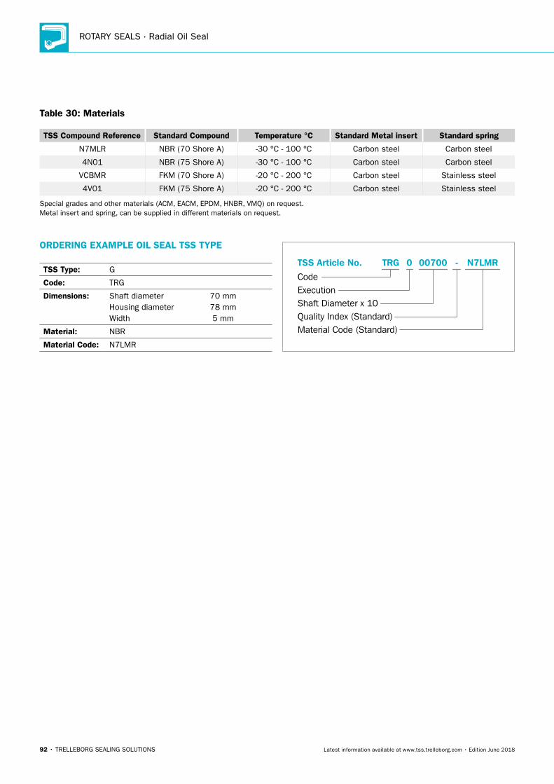
ROTARY SEALS · Radial Oil Seal
92 • TRELLEBORG SEALING SOLUTIONS Latest information available at www.tss.trelleborg.com • Edition June 2018
Table 30: Materials
TSS Compound Reference Standard Compound Temperature °C Standard Metal insert Standard spring
N7MLR NBR (70 Shore A) -30 °C - 100 °C Carbon steel Carbon steel
4N01 NBR (75 Shore A) -30 °C - 100 °C Carbon steel Carbon steel
VCBMR FKM (70 Shore A) -20 °C - 200 °C Carbon steel Stainless steel
4V01 FKM (75 Shore A) -20 °C - 200 °C Carbon steel Stainless steel
Special grades and other materials (ACM, EACM, EPDM, HNBR, VMQ) on request. Metal insert and spring, can be supplied in different materials on request.
ORDERING EXAMPLE OIL SEAL TSS TYPE
TSS Type: G
Code: TRG
Dimensions: Shaft diameter 70 mm Housing diameter 78 mm Width 5 mm
Material: NBR
Material Code: N7LMR
Material Code (Standard)
Code
TSS Article No. -
Shaft Diameter x 10Quality Index (Standard)
TRG
Execution
007000 N7LMR
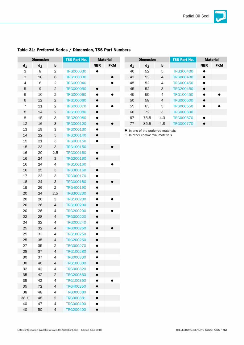
Radial Oil Seal
TRELLEBORG SEALING SOLUTIONS • 93Latest information available at www.tss.trelleborg.com • Edition June 2018
Table 31: Preferred Series / Dimension, TSS Part Numbers
Dimension TSS Part No. Material
d1 d2 b NBR FKM
3 8 2 TRG000030
3 10 6 TRG100030
4 8 2 TRG000040
5 9 2 TRG000050
6 10 2 TRG000060
6 12 2 TRG100060
7 11 2 TRG000070
8 14 2 TRG100080
8 15 3 TRG200080
12 16 3 TRG000120
13 19 3 TRG000130
14 22 3 TRG200140
15 21 3 TRG000150
15 23 3 TRG100150
16 20 2,5 TRG000160
16 24 3 TRG200160
16 24 4 TRG100160
16 25 3 TRG300160
17 23 3 TRG000170
18 24 3 TRG000180
19 26 2 TRG400190
20 24 2,5 TRG300200
20 26 3 TRG100200
20 26 4 TRG100200
20 28 4 TRG200200
22 28 4 TRG000220
24 32 4 TRG000240
25 32 4 TRG000250
25 33 4 TRG100250
25 35 4 TRG200250
27 35 2 TRG000270
28 37 4 TRG100280
30 37 4 TRG000300
30 40 4 TRG100300
32 42 4 TRG000320
35 42 2 TRG200350
35 42 4 TRG100350
35 72 4 TRG400350
38 48 4 TRG000380
38.1 48 2 TRG000381
40 47 4 TRG000400
40 50 4 TRG200400
Dimension TSS Part No. Material
d1 d2 b NBR FKM
40 52 5 TRG300400
43 53 4 TRG000430
45 52 4 TRG000450
45 52 3 TRG200450
45 55 4 TRG100450
50 58 4 TRG000500
55 63 5 TRG000550
60 72 3 TRG000600
67 75.5 4.3 TRG000670
77 85.5 4.8 TRG000770
In one of the preferred materials In other commercial materials
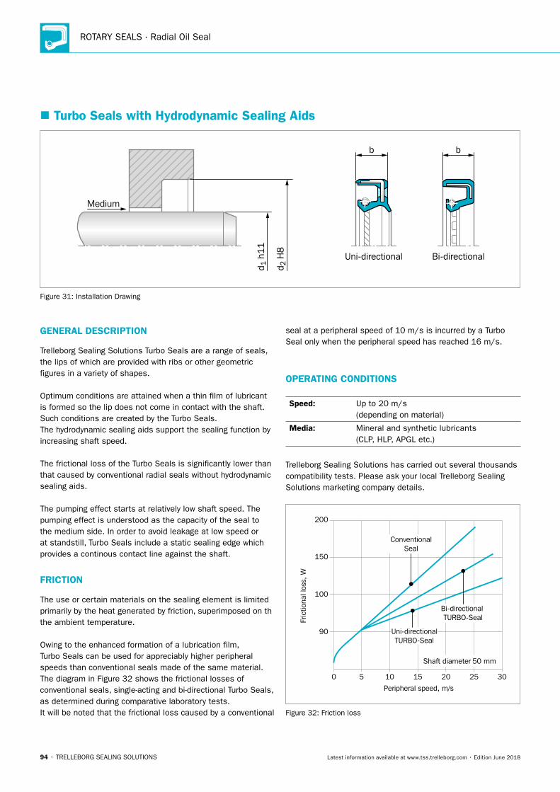
ROTARY SEALS · Radial Oil Seal
94 • TRELLEBORG SEALING SOLUTIONS Latest information available at www.tss.trelleborg.com • Edition June 2018
� Turbo Seals with Hydrodynamic Sealing Aids
b b
Medium
Uni-directional Bi-directional
d 2 H
8
d 1 h
11
Figure 31: Installation Drawing
GENERAL DESCRIPTION
Trelleborg Sealing Solutions Turbo Seals are a range of seals, the lips of which are provided with ribs or other geometric figures in a variety of shapes.
Optimum conditions are attained when a thin film of lubricant is formed so the lip does not come in contact with the shaft. Such conditions are created by the Turbo Seals.The hydrodynamic sealing aids support the sealing function by increasing shaft speed.
The frictional loss of the Turbo Seals is significantly lower than that caused by conventional radial seals without hydrodynamic sealing aids.
The pumping effect starts at relatively low shaft speed. The pumping effect is understood as the capacity of the seal to the medium side. In order to avoid leakage at low speed or at standstill, Turbo Seals include a static sealing edge which provides a continous contact line against the shaft.
FRICTION
The use or certain materials on the sealing element is limited primarily by the heat generated by friction, superimposed on th the ambient temperature.
Owing to the enhanced formation of a lubrication film, Turbo Seals can be used for appreciably higher peripheral speeds than conventional seals made of the same material. The diagram in Figure 32 shows the frictional losses of conventional seals, single-acting and bi-directional Turbo Seals, as determined during comparative laboratory tests.It will be noted that the frictional loss caused by a conventional
seal at a peripheral speed of 10 m/s is incurred by a Turbo Seal only when the peripheral speed has reached 16 m/s.
OPERATING CONDITIONS
Speed: Up to 20 m/s (depending on material)
Media: Mineral and synthetic lubricants (CLP, HLP, APGL etc.)
Trelleborg Sealing Solutions has carried out several thousands compatibility tests. Please ask your local Trelleborg Sealing Solutions marketing company details.
200
150
100
90
50 10 15 20 25 30
Peripheral speed, m/s
Shaft diameter 50 mm
ConventionalSeal
Bi-directional TURBO-Seal
Uni-directionalTURBO-Seal
Fric
tiona
l los
s, W
Figure 32: Friction loss
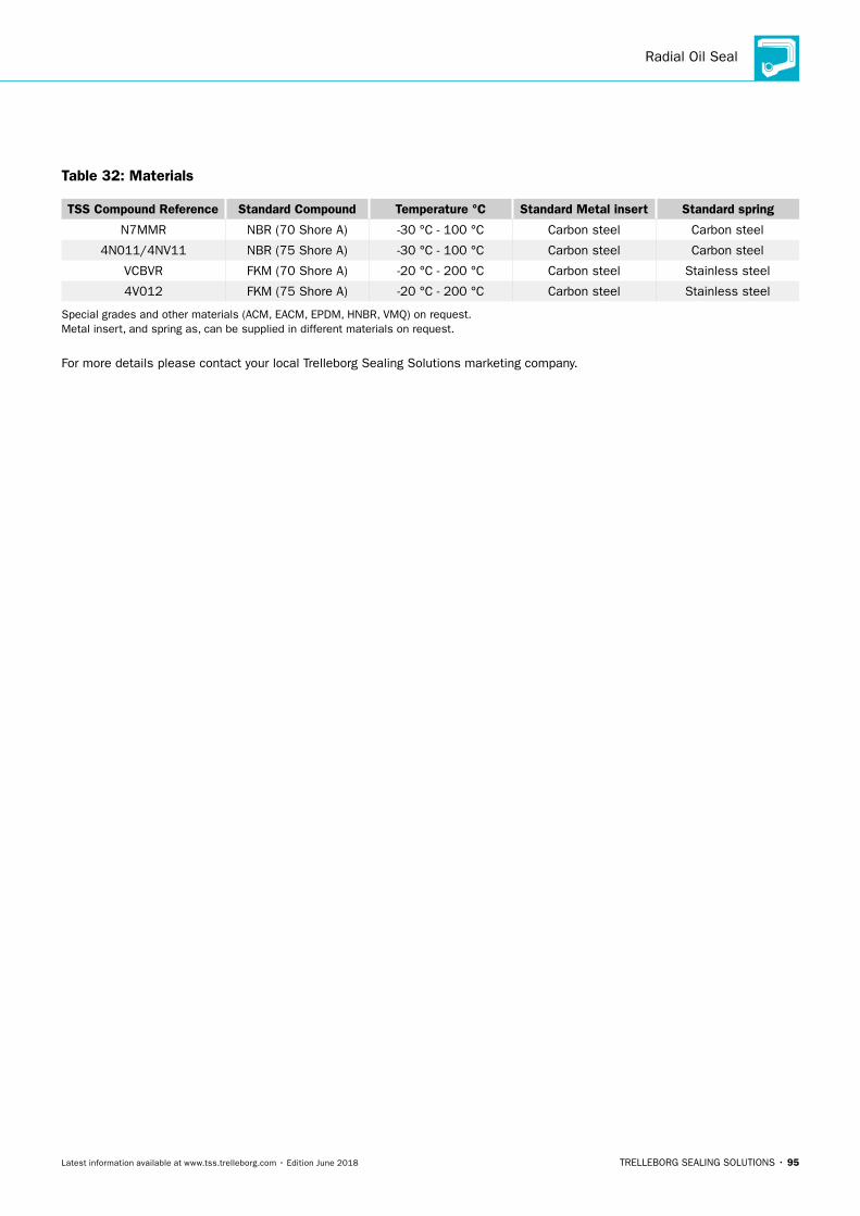
Radial Oil Seal
TRELLEBORG SEALING SOLUTIONS • 95Latest information available at www.tss.trelleborg.com • Edition June 2018
Table 32: Materials
TSS Compound Reference Standard Compound Temperature °C Standard Metal insert Standard spring
N7MMR NBR (70 Shore A) -30 °C - 100 °C Carbon steel Carbon steel
4N011/4NV11 NBR (75 Shore A) -30 °C - 100 °C Carbon steel Carbon steel
VCBVR FKM (70 Shore A) -20 °C - 200 °C Carbon steel Stainless steel
4V012 FKM (75 Shore A) -20 °C - 200 °C Carbon steel Stainless steel
Special grades and other materials (ACM, EACM, EPDM, HNBR, VMQ) on request. Metal insert, and spring as, can be supplied in different materials on request.
For more details please contact your local Trelleborg Sealing Solutions marketing company.
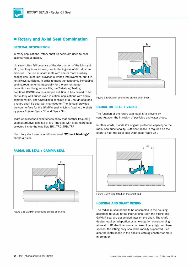
ROTARY SEALS · Radial Oil Seal
96 • TRELLEBORG SEALING SOLUTIONS Latest information available at www.tss.trelleborg.com • Edition June 2018
� Rotary and Axial Seal Combination
GENERAL DESCRIPTION
In many applications, rotary shaft lip seals are used to seal against various media.
Lip seals often fail because of the destruction of the lubricant film, resulting in rapid wear, due to the ingress of dirt, dust and moisture. The use of shaft seals with one or more auxiliary sealing lips (dust lips) provides a limited improvement, but it is not always sufficient. In order to meet the constantly increasing sealing requirements, especially for the environmental protection and long service life, the Trelleborg Sealing Solutions COMBI-seal is a simple solution. It has proved to be particularly well suited even in critical applications with heavy contamination. The COMBI-seal consists of a GAMMA seal and a rotary shaft lip seal working together. The lip seal provides the counterface for the GAMMA seal which is fixed to the shaft by press fit (see Figure 33 and Figure 34).
Years of successful experiences show that another frequently used alternative consists of a V-Ring seal with a standard seal selected inside the type list: TRC, TRD, TRB, TRF.
The rotary shaft seal should be ordered "Without Markings" on the air side.
RADIALOILSeAL+GAMMASeAL
b
Figure 33: GAMMA seal fitted on the shaft end
b
Figure 34: GAMMA seal fitted on the shaft boss
RADIALOILSeAL+V-RING
The function of the rotary axial seal is to prevent by centrifugation the intrusion of particles and water drops.
In other words, it adds it's original protection capacity to the radial seal functionality. Sufficient space is required on the shaft to host the axial seal width (see Figure 35).
B1
Figure 35: V-Ring fitted on the shaft end
HOUSING AND SHAFT DESIGN
The radial lip seal needs to be assembled in the housing according to usual fitting instructions. Both the V-Ring and GAMMA seal are assembled later on the shaft. The shaft design requires adaptation by an elongation corresponding at least to B1 (b) dimensions. In case of very high peripheral speeds, the V-Ring body should be radially supported. See also the instructions in the specific catalog chapter for more information.
Radial Oil Seal
TRELLEBORG SEALING SOLUTIONS • 97Latest information available at www.tss.trelleborg.com • Edition June 2018
PRODUCT DESCRIPTION
The combination of Radial shaft seal with V-Ring or GAMMA seals is recommended for use in heavily polluted environments.
Both the radial shaft seal and the GAMMA seal housing may also be manufactured with a different metal shell, as well as different rubber types for sealing elements. See specific paragraphs.
ADVANTAGES
- Longer service life and high function reliability
- Good IP protection for electrical motors (VDE-Norm 0470-1)
- Good protection against water splash and welding sparks
- Simple handling
- Superior total economy
- Friction loss decreases with increasing shaft speed
APPLICATION EXAMPLES
Typical applications are all equipment working in contaminated environments where dust, foreign matter and liquid splatter are present.
Some examples: - gear motors
- journal and gear transmissions
- bearing housings
- power saws
- utility vehicles
- agricultural machinery and equipment
- wheel hubs
- propeller shafts
- pumps
- hydraulic motors
- tool machinery
- equipment for steel manufacturing
- metal working machinery
OPERATING CONDITIONS
Pressure: See radial seal data
Temperature: -40 °C to +200 °C (depending on material)
Speed: Up to 10 m/s (depending on material)
Media: Mineral and synthetic oils (CLP, HLP, APGL etc.)
Trelleborg Sealing Solutions has carried out several thousands compatibility tests. Please ask your local Trelleborg Sealing Solutions marketing company for details.
IMPORTANT NOTE
The above data are maximum values and cannot be used at the same time, e. g. the maximum operating speed depends on material type, pressure and temperature.
MATERIALS
See specific chapters.
ORDERING EXAMPLE
Order components separately as per specific chapters. Order the radial oil seals "without marking".
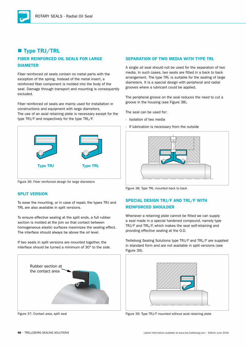
ROTARY SEALS · Radial Oil Seal
98 • TRELLEBORG SEALING SOLUTIONS Latest information available at www.tss.trelleborg.com • Edition June 2018
� Type TRJ/TRLFIBER REINFORCED OIL SEALS FOR LARGE
DIAMETER
Fiber reinforced oil seals contain no metal parts with the exception of the spring. Instead of the metal insert, a reinforced fiber component is molded into the body of the seal. Damage through transport and mounting is consequently excluded.
Fiber reinforced oil seals are mainly used for installation in constructions and equipment with large diameters.The use of an axial retaining plate is necessary except for the type TRJ/F and respectively for the type TRL/F.
Type TRJ Type TRL
Figure 36: Fiber reinforced design for large diameters
SPLIT VERSION
To ease the mounting, or in case of repair, the types TRJ and TRL are also available in split versions.
To ensure effective sealing at the split ends, a full rubber section is molded at the join so that contact between homogeneous elastic surfaces maximizes the sealing effect.The interface should always be above the oil level.
If two seals in split versions are mounted together, the interface should be turned a minimum of 30° to the side.
Rubber section atthe contact area
Figure 37: Contact area, split seal
SEPARATION OF TWO MEDIA WITH TYPE TRL
A single oil seal should not be used for the separation of two media. In such cases, two seals are fitted in a back to back arrangement. The type TRL is suitable for the sealing of large diameters. It is a special design with peripheral and radial grooves where a lubricant could be applied.
The peripheral groove on the seal reduces the need to cut a groove in the housing (see Figure 38).
The seal can be used for:
- Isolation of two media
- If lubrication is necessary from the outside
Figure 38: Type TRL mounted back to back
SPECIAL DESIGN TRJ/F AND TRL/F WITH
REINFORCED SHOULDER
Whenever a retaining plate cannot be fitted we can supply a seal made in a special hardened compound, namely type TRJ/F and TRL/F, which makes the seal self-retaining and providing effective sealing at the O.D.
Trelleborg Sealing Solutions type TRJ/F and TRL/F are supplied in standard form and are not available in split versions (see Figure 39).
Figure 39: Type TRJ/F mounted without axial retaining plate
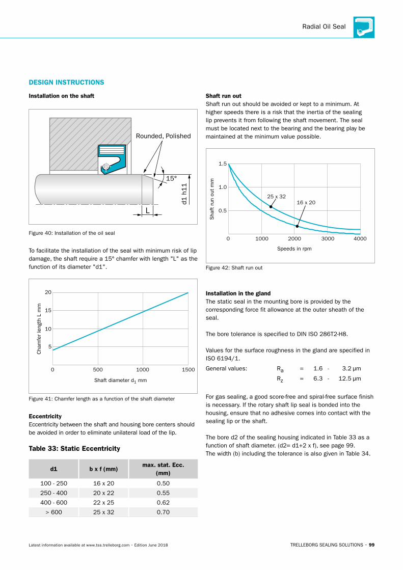
Radial Oil Seal
TRELLEBORG SEALING SOLUTIONS • 99Latest information available at www.tss.trelleborg.com • Edition June 2018
Installation on the shaft
Rounded, Polished
15°
L
d1 h
11
Figure 40: Installation of the oil seal
To facilitate the installation of the seal with minimum risk of lip damage, the shaft require a 15° chamfer with length "L" as the function of its diameter "d1".
0
10
15
20
5
Cha
mfe
r le
ngth
L m
m
Shaft diameter d1 mm
500 15001000
Figure 41: Chamfer length as a function of the shaft diameter
EccentricityEccentricity between the shaft and housing bore centers should be avoided in order to eliminate unilateral load of the lip.
Table 33: Static Eccentricity
d1 b x f (mm)max. stat. Ecc.
(mm)
100 - 250 16 x 20 0.50
250 - 400 20 x 22 0.55
400 - 600 22 x 25 0.62
> 600 25 x 32 0.70
Shaft run outShaft run out should be avoided or kept to a minimum. At higher speeds there is a risk that the inertia of the sealing lip prevents it from following the shaft movement. The seal must be located next to the bearing and the bearing play be maintained at the minimum value possible.
1.0
1.5
0.5S
haft
run
out
mm
Speeds in rpm
0 4000
25 x 3216 x 20
300020001000
Figure 42: Shaft run out
Installation in the glandThe static seal in the mounting bore is provided by the corresponding force fit allowance at the outer sheath of the seal.
The bore tolerance is specified to DIN ISO 286T2-H8.
Values for the surface roughness in the gland are specified in ISO 6194/1.
General values: Ra = 1.6 - 3.2 μm
Rz = 6.3 - 12.5 μm
For gas sealing, a good score-free and spiral-free surface finish is necessary. If the rotary shaft lip seal is bonded into the housing, ensure that no adhesive comes into contact with the sealing lip or the shaft.
The bore d2 of the sealing housing indicated in Table 33 as a function of shaft diameter. (d2= d1+2 x f), see page 99. The width (b) including the tolerance is also given in Table 34.
DESIGN INSTRUCTIONS
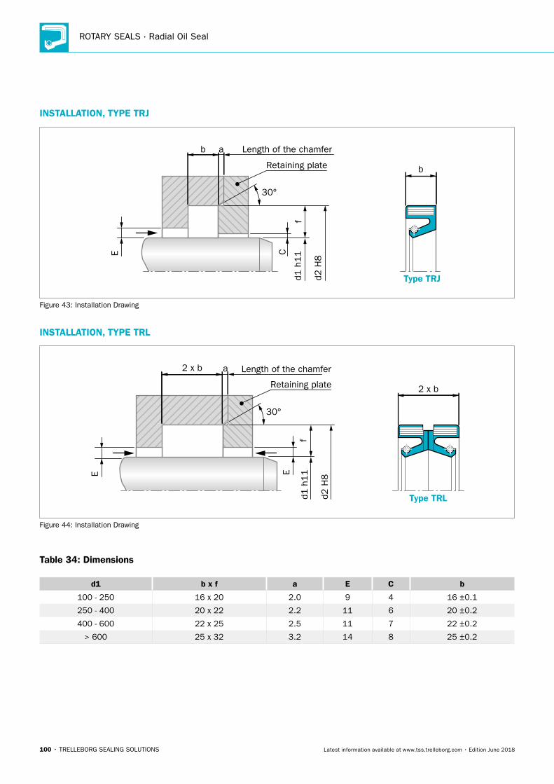
ROTARY SEALS · Radial Oil Seal
100 • TRELLEBORG SEALING SOLUTIONS Latest information available at www.tss.trelleborg.com • Edition June 2018
b
b a
f
30°
C
E
Retaining plate
Length of the chamfer
Type TRJd1 h
11
d2 H
8Figure 43: Installation Drawing
INSTALLATION, TYPE TRL
E E
2 x b
2 x b
30°
a Length of the chamfer
Type TRL
Retaining plate
fd1
h11
d2 H
8
Figure 44: Installation Drawing
Table 34: Dimensions
d1 b x f a E C b
100 - 250 16 x 20 2.0 9 4 16 ±0.1
250 - 400 20 x 22 2.2 11 6 20 ±0.2
400 - 600 22 x 25 2.5 11 7 22 ±0.2
> 600 25 x 32 3.2 14 8 25 ±0.2
INSTALLATION, TYPE TRJ
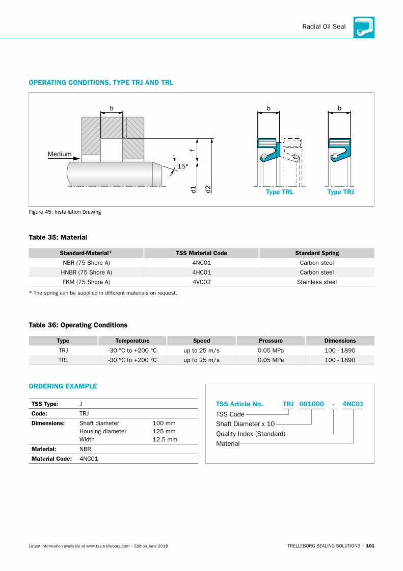
Radial Oil Seal
TRELLEBORG SEALING SOLUTIONS • 101Latest information available at www.tss.trelleborg.com • Edition June 2018
OPERATING CONDITIONS, TYPE TRJ AND TRL
d1
d2
Type TRL
15°
Medium
b
Type TRJf
bb
Figure 45: Installation Drawing
Table 35: Material
Standard-Material* TSS Material Code Standard Spring
NBR (75 Shore A) 4NC01 Carbon steel
HNBR (75 Shore A) 4HC01 Carbon steel
FKM (75 Shore A) 4VC02 Stainless steel
* The spring can be supplied in different materials on request.
Table 36: Operating Conditions
Type Temperature Speed Pressure Dimensions
TRJ -30 °C to +200 °C up to 25 m/s 0.05 MPa 100 - 1890
TRL -30 °C to +200 °C up to 25 m/s 0.05 MPa 100 - 1890
ORDERING EXAMPLE
TSS Type: J
Code: TRJ
Dimensions: Shaft diameter 100 mm Housing diameter 125 mm Width 12.5 mm
Material: NBR
Material Code: 4NC01
TSS Code
TSS Article No. 001000
Shaft Diameter x 10
Material
TRJ 4NC01-
Quality Index (Standard)
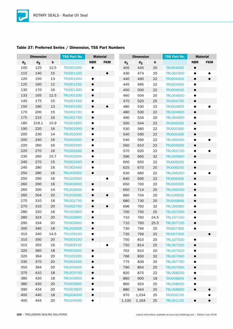
ROTARY SEALS · Radial Oil Seal
102 • TRELLEBORG SEALING SOLUTIONS Latest information available at www.tss.trelleborg.com • Edition June 2018
Table 37: Preferred Series / Dimension, TSS Part Numbers
Dimension TSS Part No. Material
d1 d2 b NBR FKM
100 125 12.5 TRJ001000
115 140 15 TRJ001150
120 150 13 TRJ001200
125 160 12 TRJ001250
130 170 16 TRJ001300
133 165 12.5 TRL001330
145 175 15 TRJ001450
150 180 13 TRJ001500
170 200 15 TRJ001700
175 215 16 TRL001750
180 218.1 15.9 TRJ001800
190 220 16 TRJ001900
200 230 14 TRL002000
200 240 16 TRJ002000
220 260 16 TRJ002200
220 270 16 TRJ202200
230 260 15.7 TRJ002300
240 270 15 TRJ002400
240 280 16 TRJ302400
250 280 16 TRL002500
250 290 16 TRJ102500
260 290 16 TRJ002600
260 300 14 TRL002600
260 304 20 TRJ102600
270 310 18 TRL002700
270 310 20 TRJ002700
280 320 16 TRJ102800
280 324 20 TRJ202800
290 334 20 TRJ002900
300 340 18 TRL003000
310 340 14.5 TRJ103100
310 350 20 TRJ003100
315 355 16 TRJ003150
320 360 18 TRJ003200
320 364 20 TRJ103200
330 370 20 TRJ003300
350 394 20 TRL003500
370 410 18 TRL003700
380 420 18 TRL003800
380 420 20 TRJ003800
390 434 20 TRJ003900
400 440 18 TRL004000
400 444 20 TRJ104000
Dimension TSS Part No. Material
d1 d2 b NBR FKM
405 445 20 TRJ004050
430 474 20 TRL004300
440 490 22 TRJ004400
445 495 22 TRJ004450
450 500 22 TRJ004500
460 504 20 TRL004600
470 520 25 TRJ004700
480 530 22 TRJ004800
480 530 22 TRL004800
490 534 20 TRL004900
500 544 22 TRJ005000
530 580 22 TRJ005300
540 590 22 TRJ005400
540 590 22 TRL005400
560 610 22 TRJ005600
570 620 22 TRL005700
596 660 32 TRL005960
600 650 22 TRJ006000
625 670 20 TRJ006250
630 680 22 TRL006300
640 690 22 TRJ006400
650 700 22 TRJ006500
650 714 25 TRL006500
660 704 20 TRJ106600
680 730 20 TRJ006800
696 760 32 TRL006960
700 750 25 TRL007000
710 760 24.5 TRL107100
710 760 25.5 TRL007100
730 794 25 TRJ007300
735 799 25 TRJ007350
750 810 25 TRL107500
750 814 25 TRL007500
762 810 20 TRL007620
766 830 32 TRL007660
775 839 25 TRL007750
790 854 25 TRL007900
820 870 22 TRL008200
860 900 18 TRJ008600
860 924 25 TRL008600
880 944 25 TRL008800
970 1,034 25 TRJ009700
1,100 1,164 25 TRL0X1100

Radial Oil Seal
TRELLEBORG SEALING SOLUTIONS • 103Latest information available at www.tss.trelleborg.com • Edition June 2018
Table 38: Further dimensions for Type TRJ/TRL
Dimensions Type
d1 d2 b f TRJ TRL
100.0 115.0 8.9 7.5
100.0 115.0 9.0 7.5
100.0 120.0 13.0 10.0
100.0 125.0 13.0 12.5
100.0 125.0 15.0 12.5
100.0 125.4 12.7 12.7
100.0 130.0 12.0 15.0
100.0 130.0 15.0 15.0
100.0 132.0 12.5 16.0
100.0 140.0 16.0 20.0
105.0 129.0 13.0 12.0
105.0 130.0 12.0 12.5
105.0 130.0 13.0 12.5
105.0 133.5 12.7 14.3
105.0 137.0 16.0 16.0
105.0 140.0 12.0 17.5
105.0 143.0 16.0 19.0
105.0 145.0 16.0 20.0
110.0 126.0 9.0 8.0
110.0 126.0 12.0 8.0
110.0 130.0 9.0 10.0
110.0 130.0 12.0 10.0
110.0 130.0 13.0 10.0
110.0 135.0 12.0 12.5
110.0 140.0 12.0 15.0
110.0 140.0 14.0 15.0
110.0 140.0 15.0 15.0
110.0 140.0 16.0 15.0
110.0 141.0 13.7 15.5
110.0 145.0 19.0 17.5
110.0 150.0 16.0 20.0
115.0 137.0 8.8 11.0
115.0 137.0 9.0 11.0
115.0 140.0 12.0 12.5
115.0 140.0 13.0 12.5
115.0 140.4 9.5 12.7
115.0 145.0 12.0 15.0
115.0 145.0 15.0 15.0
115.0 150.0 15.0 17.5
115.0 155.0 16.0 20.0
118.0 140.0 14.0 11.0
120.0 140.0 12.5 10.0
Dimensions Type
d1 d2 b f TRJ TRL
120.0 140.0 13.0 10.0
120.0 144.0 14.5 10.0
120.0 144.0 15.5 12.0
120.0 145.0 15.5 12.5
120.0 150.0 13.0 15.0
120.0 150.0 15.0 15.0
120.0 150.0 16.0 15.0
120.0 152.0 16.0 16.0
120.0 160.0 12.0 20.0
120.0 160.0 16.0 20.0
120.0 170.0 15.0 25.0
125.0 140.0 10.0 7.5
125.0 150.0 12.0 12.5
125.0 150.0 15.0 12.5
125.0 153.5 12.7 14.2
125.0 155.0 12.0 15.0
125.0 160.0 12.0 17.5
125.0 160.0 13.0 17.5
125.0 160.0 15.0 17.5
125.0 165.0 15.0 20.0
125.0 165.0 16.0 20.0
127.0 157.0 15.0 15.0
128.0 165.0 15.0 18.5
130.0 150.0 10.0 10.0
130.0 150.0 12.0 10.0
130.0 155.0 10.0 12.5
130.0 155.0 15.5 12.5
130.0 160.0 12.0 15.0
130.0 160.0 15.0 15.0
130.0 160.0 16.0 15.0
130.0 165.0 13.0 17.5
130.0 170.0 13.0 20.0
130.0 170.0 16.0 20.0
133.0 165.0 12.5 16.0
134.0 169.0 15.0 17.5
135.0 157.0 8.0 11.0
135.0 160.0 12.0 12.5
135.0 165.0 13.0 15.0
135.0 167.0 15.0 16.0
135.0 160.0 12.0 12.5
These additional dimensions available on request. Please contact Trelleborg sealing solutions.

ROTARY SEALS · Radial Oil Seal
104 • TRELLEBORG SEALING SOLUTIONS Latest information available at www.tss.trelleborg.com • Edition June 2018
Dimensions Type
d1 d2 b f TRJ TRL
135.0 165.0 13.0 15.0
135.0 167.0 15.0 16.0
135.0 160.0 12.0 12.5
135.0 165.0 13.0 15.0
135.0 167.0 15.0 16.0
135.0 170.0 12.0 17.5
135.0 170.0 13.0 17.5
135.0 170.0 16.5 17.5
135.0 175.0 16.0 20.0
136.0 160.0 10.0 12.0
138.0 180.0 15.0 21.0
139.0 155.0 10.0 8.0
139.0 169.0 14.6 15.0
140.0 155.0 10.0 7.5
140.0 160.0 13.0 10.0
140.0 165.0 15.0 12.5
140.0 168.0 21.0 14.0
140.0 170.0 15.0 15.0
140.0 180.0 12.0 20.0
140.0 180.0 15.0 20.0
140.0 180.0 16.0 20.0
140.0 190.0 15.0 25.0
143.0 165.0 10.0 11.0
144.0 180.0 15.0 18.0
145.0 170.0 13.0 12.5
145.0 170.0 15.0 12.5
145.0 180.0 12.0 17.5
145.0 180.0 14.0 17.5
149.0 179.0 13.0 15.0
149.0 180.0 16.0 15.5
150.0 172.0 12.7 11.0
150.0 180.0 12.0 15.0
150.0 180.0 13.0 15.0
150.0 180.0 14.0 15.0
150.0 180.0 15.0 15.0
150.0 185.0 15.0 17.5
150.0 188.0 16.0 19.0
150.0 190.0 16.0 20.0
150.0 190.0 20.0 20.0
152.0 180.0 14.0 14.0
152.0 190.0 19.0 19.0
154.0 180.0 12.2 13.0
155.0 175.0 10.8 10.0
155.0 180.0 12.5 12.5
Dimensions Type
d1 d2 b f TRJ TRL
155.0 180.0 15.0 12.5
155.0 190.0 13.0 17.5
156.0 195.0 15.0 19.5
159.0 200.0 16.0 20.5
160.0 188.0 21.0 14.0
160.0 190.0 15.0 15.0
160.0 190.0 16.0 15.0
160.0 200.0 16.0 20.0
165.0 190.0 15.0 12.5
165.0 195.0 15.0 15.0
165.0 200.0 15.0 17.5
165.0 203.0 19.0 19.0
165.0 205.0 16.0 20.0
168.0 200.0 16.0 16.0
169.0 200.0 12.0 15.5
169.0 201.0 12.5 16.0
170.0 192.0 10.7 11.0
170.0 195.0 14.2 12.5
170.0 200.0 12.0 15.0
170.0 200.0 15.0 15.0
170.0 205.0 18.0 17.5
170.0 210.0 16.0 20.0
170.0 220.0 15.0 25.0
170.0 223.0 20.0 26.5
174.0 214.0 16.0 20.0
175.0 200.0 15.0 12.7
175.0 205.0 15.0 15.0
175.0 215.0 15.0 20.0
175.0 215.0 16.0 20.0
180.0 200.0 15.0 10.0
180.0 205.0 12.5 12.5
180.0 210.0 12.0 15.0
180.0 210.0 15.0 15.0
180.0 212.0 16.0 16.0
180.0 215.0 15.0 17.5
180.0 216.0 21.8 18.0
180.0 220.0 13.0 20.0
180.0 220.0 16.0 20.0
180.0 230.0 16.0 25.0
182.0 215.0 16.0 16.5
185.0 210.0 13.0 12.5
185.0 215.0 15.0 15.0
These additional dimensions available on request. Please contact Trelleborg sealing solutions.
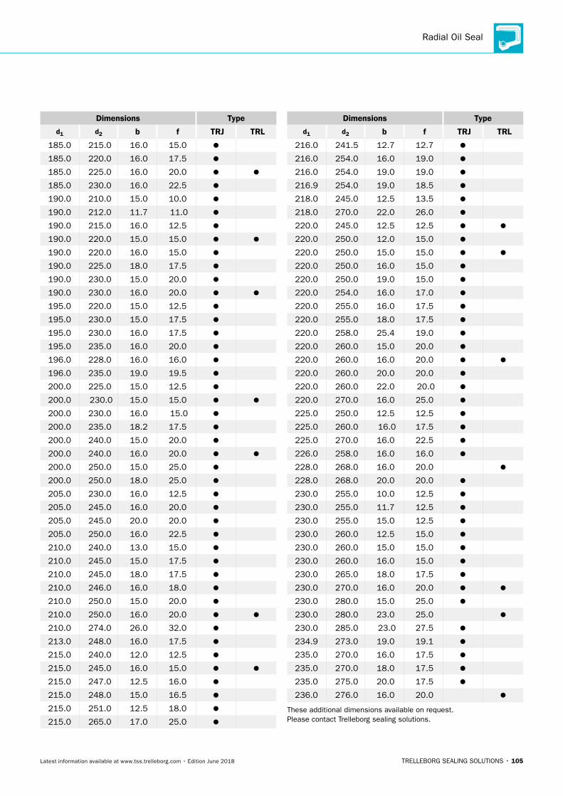
Radial Oil Seal
TRELLEBORG SEALING SOLUTIONS • 105Latest information available at www.tss.trelleborg.com • Edition June 2018
Dimensions Type
d1 d2 b f TRJ TRL
185.0 215.0 16.0 15.0
185.0 220.0 16.0 17.5
185.0 225.0 16.0 20.0
185.0 230.0 16.0 22.5
190.0 210.0 15.0 10.0
190.0 212.0 11.7 11.0
190.0 215.0 16.0 12.5
190.0 220.0 15.0 15.0
190.0 220.0 16.0 15.0
190.0 225.0 18.0 17.5
190.0 230.0 15.0 20.0
190.0 230.0 16.0 20.0
195.0 220.0 15.0 12.5
195.0 230.0 15.0 17.5
195.0 230.0 16.0 17.5
195.0 235.0 16.0 20.0
196.0 228.0 16.0 16.0
196.0 235.0 19.0 19.5
200.0 225.0 15.0 12.5
200.0 230.0 15.0 15.0
200.0 230.0 16.0 15.0
200.0 235.0 18.2 17.5
200.0 240.0 15.0 20.0
200.0 240.0 16.0 20.0
200.0 250.0 15.0 25.0
200.0 250.0 18.0 25.0
205.0 230.0 16.0 12.5
205.0 245.0 16.0 20.0
205.0 245.0 20.0 20.0
205.0 250.0 16.0 22.5
210.0 240.0 13.0 15.0
210.0 245.0 15.0 17.5
210.0 245.0 18.0 17.5
210.0 246.0 16.0 18.0
210.0 250.0 15.0 20.0
210.0 250.0 16.0 20.0
210.0 274.0 26.0 32.0
213.0 248.0 16.0 17.5
215.0 240.0 12.0 12.5
215.0 245.0 16.0 15.0
215.0 247.0 12.5 16.0
215.0 248.0 15.0 16.5
215.0 251.0 12.5 18.0
215.0 265.0 17.0 25.0
Dimensions Type
d1 d2 b f TRJ TRL
216.0 241.5 12.7 12.7
216.0 254.0 16.0 19.0
216.0 254.0 19.0 19.0
216.9 254.0 19.0 18.5
218.0 245.0 12.5 13.5
218.0 270.0 22.0 26.0
220.0 245.0 12.5 12.5
220.0 250.0 12.0 15.0
220.0 250.0 15.0 15.0
220.0 250.0 16.0 15.0
220.0 250.0 19.0 15.0
220.0 254.0 16.0 17.0
220.0 255.0 16.0 17.5
220.0 255.0 18.0 17.5
220.0 258.0 25.4 19.0
220.0 260.0 15.0 20.0
220.0 260.0 16.0 20.0
220.0 260.0 20.0 20.0
220.0 260.0 22.0 20.0
220.0 270.0 16.0 25.0
225.0 250.0 12.5 12.5
225.0 260.0 16.0 17.5
225.0 270.0 16.0 22.5
226.0 258.0 16.0 16.0
228.0 268.0 16.0 20.0
228.0 268.0 20.0 20.0
230.0 255.0 10.0 12.5
230.0 255.0 11.7 12.5
230.0 255.0 15.0 12.5
230.0 260.0 12.5 15.0
230.0 260.0 15.0 15.0
230.0 260.0 16.0 15.0
230.0 265.0 18.0 17.5
230.0 270.0 16.0 20.0
230.0 280.0 15.0 25.0
230.0 280.0 23.0 25.0
230.0 285.0 23.0 27.5
234.9 273.0 19.0 19.1
235.0 270.0 16.0 17.5
235.0 270.0 18.0 17.5
235.0 275.0 20.0 17.5
236.0 276.0 16.0 20.0
These additional dimensions available on request. Please contact Trelleborg sealing solutions.
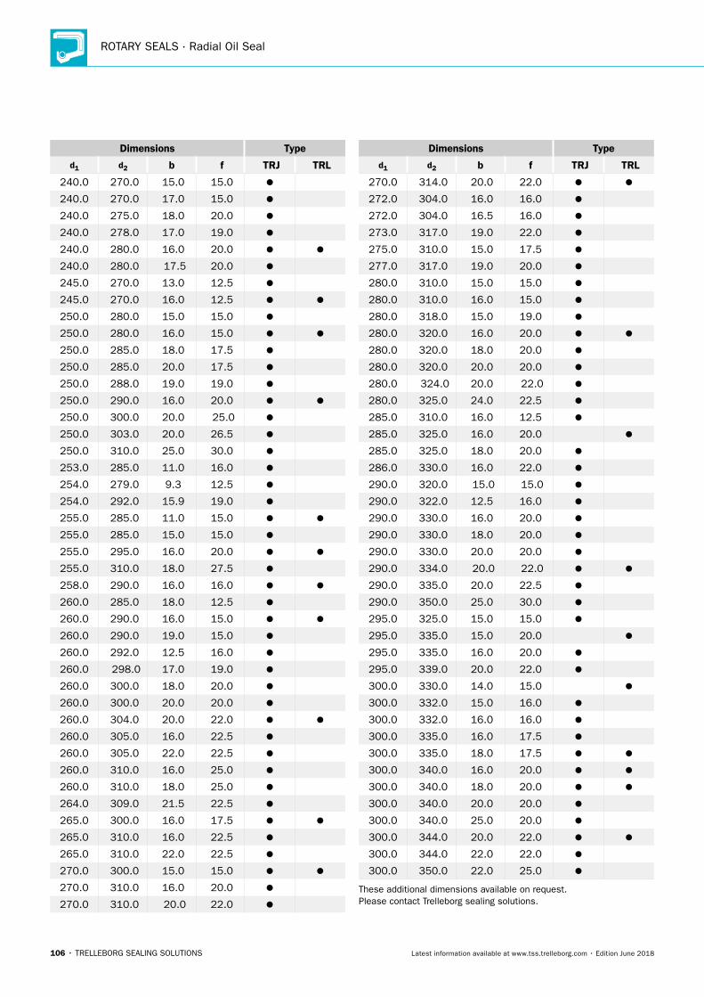
ROTARY SEALS · Radial Oil Seal
106 • TRELLEBORG SEALING SOLUTIONS Latest information available at www.tss.trelleborg.com • Edition June 2018
Dimensions Type
d1 d2 b f TRJ TRL
240.0 270.0 15.0 15.0
240.0 270.0 17.0 15.0
240.0 275.0 18.0 20.0
240.0 278.0 17.0 19.0
240.0 280.0 16.0 20.0
240.0 280.0 17.5 20.0
245.0 270.0 13.0 12.5
245.0 270.0 16.0 12.5
250.0 280.0 15.0 15.0
250.0 280.0 16.0 15.0
250.0 285.0 18.0 17.5
250.0 285.0 20.0 17.5
250.0 288.0 19.0 19.0
250.0 290.0 16.0 20.0
250.0 300.0 20.0 25.0
250.0 303.0 20.0 26.5
250.0 310.0 25.0 30.0
253.0 285.0 11.0 16.0
254.0 279.0 9.3 12.5
254.0 292.0 15.9 19.0
255.0 285.0 11.0 15.0
255.0 285.0 15.0 15.0
255.0 295.0 16.0 20.0
255.0 310.0 18.0 27.5
258.0 290.0 16.0 16.0
260.0 285.0 18.0 12.5
260.0 290.0 16.0 15.0
260.0 290.0 19.0 15.0
260.0 292.0 12.5 16.0
260.0 298.0 17.0 19.0
260.0 300.0 18.0 20.0
260.0 300.0 20.0 20.0
260.0 304.0 20.0 22.0
260.0 305.0 16.0 22.5
260.0 305.0 22.0 22.5
260.0 310.0 16.0 25.0
260.0 310.0 18.0 25.0
264.0 309.0 21.5 22.5
265.0 300.0 16.0 17.5
265.0 310.0 16.0 22.5
265.0 310.0 22.0 22.5
270.0 300.0 15.0 15.0
270.0 310.0 16.0 20.0
270.0 310.0 20.0 22.0
Dimensions Type
d1 d2 b f TRJ TRL
270.0 314.0 20.0 22.0
272.0 304.0 16.0 16.0
272.0 304.0 16.5 16.0
273.0 317.0 19.0 22.0
275.0 310.0 15.0 17.5
277.0 317.0 19.0 20.0
280.0 310.0 15.0 15.0
280.0 310.0 16.0 15.0
280.0 318.0 15.0 19.0
280.0 320.0 16.0 20.0
280.0 320.0 18.0 20.0
280.0 320.0 20.0 20.0
280.0 324.0 20.0 22.0
280.0 325.0 24.0 22.5
285.0 310.0 16.0 12.5
285.0 325.0 16.0 20.0
285.0 325.0 18.0 20.0
286.0 330.0 16.0 22.0
290.0 320.0 15.0 15.0
290.0 322.0 12.5 16.0
290.0 330.0 16.0 20.0
290.0 330.0 18.0 20.0
290.0 330.0 20.0 20.0
290.0 334.0 20.0 22.0
290.0 335.0 20.0 22.5
290.0 350.0 25.0 30.0
295.0 325.0 15.0 15.0
295.0 335.0 15.0 20.0
295.0 335.0 16.0 20.0
295.0 339.0 20.0 22.0
300.0 330.0 14.0 15.0
300.0 332.0 15.0 16.0
300.0 332.0 16.0 16.0
300.0 335.0 16.0 17.5
300.0 335.0 18.0 17.5
300.0 340.0 16.0 20.0
300.0 340.0 18.0 20.0
300.0 340.0 20.0 20.0
300.0 340.0 25.0 20.0
300.0 344.0 20.0 22.0
300.0 344.0 22.0 22.0
300.0 350.0 22.0 25.0
These additional dimensions available on request. Please contact Trelleborg sealing solutions.

Radial Oil Seal
TRELLEBORG SEALING SOLUTIONS • 107Latest information available at www.tss.trelleborg.com • Edition June 2018
Dimensions Type
d1 d2 b f TRJ TRL
300.0 350.0 25.0 25.0
300.0 360.0 25.0 30.0
300.0 364.0 25.0 32.0
300.0 370.0 18.0 35.0
305.0 340.0 15.0 17.5
305.0 349.0 20.0 22.0
305.0 355.0 15.0 25.0
305.0 362.0 19.0 28.5
310.0 350.0 17.5 20.0
310.0 350.0 18.0 20.0
310.0 354.0 20.0 22.0
310.0 355.0 24.0 22.5
310.0 370.0 28.0 30.0
314.0 355.0 20.0 20.5
315.0 347.0 13.0 16.0
315.0 355.0 18.0 20.0
315.0 359.0 20.0 22.0
315.0 360.0 20.0 22.5
315.0 365.0 20.0 25.0
315.0 380.0 29.0 32.5
317.0 361.0 20.0 22.0
320.0 350.0 15.0 15.0
320.0 355.0 16.0 17.5
320.0 360.0 18.0 20.0
320.0 360.0 20.0 20.0
320.0 364.0 20.0 22.0
323.0 363.0 16.0 20.0
325.0 365.0 16.0 20.0
325.0 365.0 20.0 20.0
325.0 369.0 22.0 20.0
325.0 369.0 20.0 22.0
325.0 375.0 22.0 25.0
328.0 372.0 20.2 22.0
330.0 370.0 18.0 20.0
330.0 370.0 20.0 20.0
330.0 374.0 19.0 22.0
330.0 374.0 20.0 22.0
330.0 374.0 22.0 22.0
335.0 375.0 18.0 20.0
335.0 379.0 20.0 22.0
335.0 400.0 35.0 32.5
338.0 382.0 20.0 22.0
340.0 370.0 15.0 15.0
340.0 370.0 18.0 15.0
Dimensions Type
d1 d2 b f TRJ TRL
340.0 370.0 20.0 15.0
340.0 372.0 16.0 16.0
340.0 373.0 16.0 16.5
340.0 378.0 16.0 19.0
340.0 380.0 18.0 20.0
340.0 380.0 20.0 20.0
340.0 384.0 20.0 22.0
340.0 400.0 28.0 30.0
345.0 389.0 20.0 22.0
345.0 395.0 20.0 25.0
346.0 390.0 20.0 22.0
348.0 380.0 16.0 16.0
350.0 380.0 16.0 15.0
350.0 390.0 15.0 20.0
350.0 390.0 16.0 20.0
350.0 390.0 18.0 20.0
350.0 390.0 20.0 20.0
350.0 394.0 20.0 22.0
350.0 394.0 22.0 22.0
350.0 405.0 20.0 27.5
355.0 379.0 20.0 12.0
355.0 385.0 16.0 15.0
355.0 394.0 20.0 19.5
355.0 410.0 25.0 27.5
360.0 390.0 18.0 15.0
360.0 400.0 16.0 20.0
360.0 400.0 18.0 20.0
360.0 400.0 20.0 20.0
360.0 404.0 20.0 22.0
360.0 410.0 22.0 25.0
362.0 400.0 20.0 19.0
362.0 406.0 19.5 22.0
362.0 406.0 20.0 22.0
362.0 406.0 22.0 22.0
363.0 418.0 20.0 27.5
365.0 405.0 18.0 20.0
365.0 409.0 20.0 22.0
370.0 410.0 15.0 20.0
370.0 410.0 18.0 20.0
370.0 410.0 20.0 20.0
370.0 414.0 19.0 22.0
370.0 414.0 20.0 22.0
These additional dimensions available on request. Please contact Trelleborg sealing solutions.
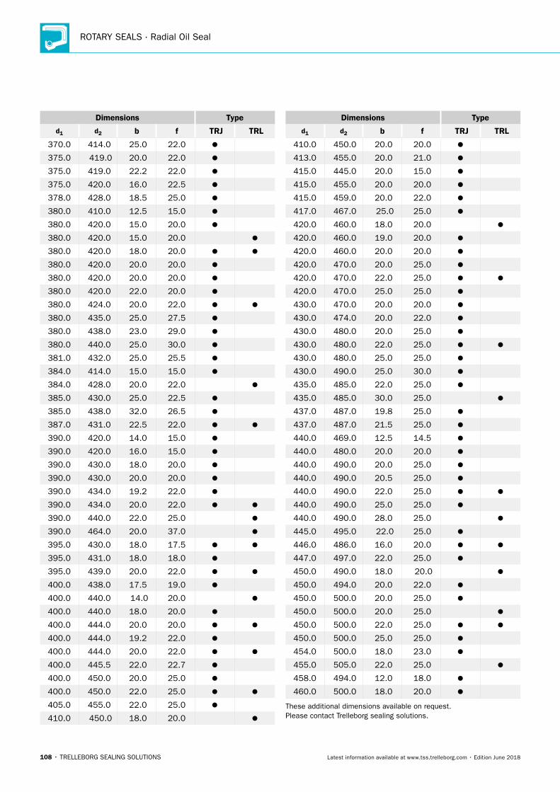
ROTARY SEALS · Radial Oil Seal
108 • TRELLEBORG SEALING SOLUTIONS Latest information available at www.tss.trelleborg.com • Edition June 2018
Dimensions Type
d1 d2 b f TRJ TRL
370.0 414.0 25.0 22.0
375.0 419.0 20.0 22.0
375.0 419.0 22.2 22.0
375.0 420.0 16.0 22.5
378.0 428.0 18.5 25.0
380.0 410.0 12.5 15.0
380.0 420.0 15.0 20.0
380.0 420.0 15.0 20.0
380.0 420.0 18.0 20.0
380.0 420.0 20.0 20.0
380.0 420.0 20.0 20.0
380.0 420.0 22.0 20.0
380.0 424.0 20.0 22.0
380.0 435.0 25.0 27.5
380.0 438.0 23.0 29.0
380.0 440.0 25.0 30.0
381.0 432.0 25.0 25.5
384.0 414.0 15.0 15.0
384.0 428.0 20.0 22.0
385.0 430.0 25.0 22.5
385.0 438.0 32.0 26.5
387.0 431.0 22.5 22.0
390.0 420.0 14.0 15.0
390.0 420.0 16.0 15.0
390.0 430.0 18.0 20.0
390.0 430.0 20.0 20.0
390.0 434.0 19.2 22.0
390.0 434.0 20.0 22.0
390.0 440.0 22.0 25.0
390.0 464.0 20.0 37.0
395.0 430.0 18.0 17.5
395.0 431.0 18.0 18.0
395.0 439.0 20.0 22.0
400.0 438.0 17.5 19.0
400.0 440.0 14.0 20.0
400.0 440.0 18.0 20.0
400.0 444.0 20.0 20.0
400.0 444.0 19.2 22.0
400.0 444.0 20.0 22.0
400.0 445.5 22.0 22.7
400.0 450.0 20.0 25.0
400.0 450.0 22.0 25.0
405.0 455.0 22.0 25.0
410.0 450.0 18.0 20.0
Dimensions Type
d1 d2 b f TRJ TRL
410.0 450.0 20.0 20.0
413.0 455.0 20.0 21.0
415.0 445.0 20.0 15.0
415.0 455.0 20.0 20.0
415.0 459.0 20.0 22.0
417.0 467.0 25.0 25.0
420.0 460.0 18.0 20.0
420.0 460.0 19.0 20.0
420.0 460.0 20.0 20.0
420.0 470.0 20.0 25.0
420.0 470.0 22.0 25.0
420.0 470.0 25.0 25.0
430.0 470.0 20.0 20.0
430.0 474.0 20.0 22.0
430.0 480.0 20.0 25.0
430.0 480.0 22.0 25.0
430.0 480.0 25.0 25.0
430.0 490.0 25.0 30.0
435.0 485.0 22.0 25.0
435.0 485.0 30.0 25.0
437.0 487.0 19.8 25.0
437.0 487.0 21.5 25.0
440.0 469.0 12.5 14.5
440.0 480.0 20.0 20.0
440.0 490.0 20.0 25.0
440.0 490.0 20.5 25.0
440.0 490.0 22.0 25.0
440.0 490.0 25.0 25.0
440.0 490.0 28.0 25.0
445.0 495.0 22.0 25.0
446.0 486.0 16.0 20.0
447.0 497.0 22.0 25.0
450.0 490.0 18.0 20.0
450.0 494.0 20.0 22.0
450.0 500.0 20.0 25.0
450.0 500.0 20.0 25.0
450.0 500.0 22.0 25.0
450.0 500.0 25.0 25.0
454.0 500.0 18.0 23.0
455.0 505.0 22.0 25.0
458.0 494.0 12.0 18.0
460.0 500.0 18.0 20.0
These additional dimensions available on request. Please contact Trelleborg sealing solutions.
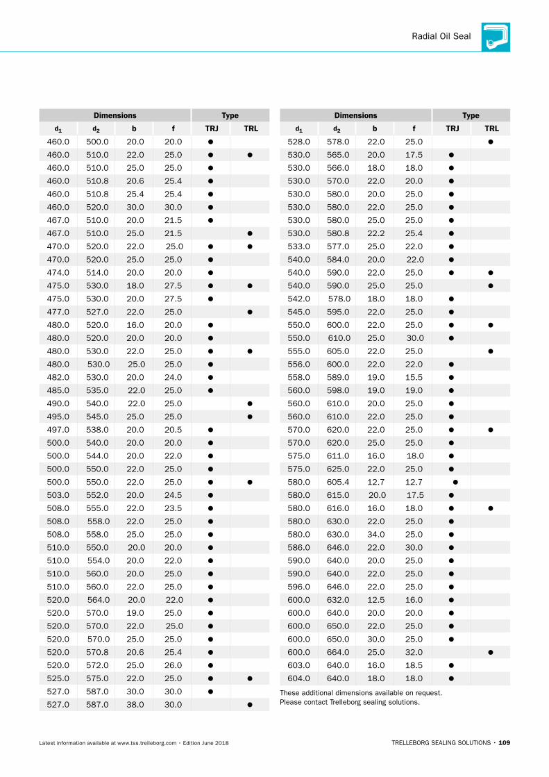
Radial Oil Seal
TRELLEBORG SEALING SOLUTIONS • 109Latest information available at www.tss.trelleborg.com • Edition June 2018
Dimensions Type
d1 d2 b f TRJ TRL
460.0 500.0 20.0 20.0
460.0 510.0 22.0 25.0
460.0 510.0 25.0 25.0
460.0 510.8 20.6 25.4
460.0 510.8 25.4 25.4
460.0 520.0 30.0 30.0
467.0 510.0 20.0 21.5
467.0 510.0 25.0 21.5
470.0 520.0 22.0 25.0
470.0 520.0 25.0 25.0
474.0 514.0 20.0 20.0
475.0 530.0 18.0 27.5
475.0 530.0 20.0 27.5
477.0 527.0 22.0 25.0
480.0 520.0 16.0 20.0
480.0 520.0 20.0 20.0
480.0 530.0 22.0 25.0
480.0 530.0 25.0 25.0
482.0 530.0 20.0 24.0
485.0 535.0 22.0 25.0
490.0 540.0 22.0 25.0
495.0 545.0 25.0 25.0
497.0 538.0 20.0 20.5
500.0 540.0 20.0 20.0
500.0 544.0 20.0 22.0
500.0 550.0 22.0 25.0
500.0 550.0 22.0 25.0
503.0 552.0 20.0 24.5
508.0 555.0 22.0 23.5
508.0 558.0 22.0 25.0
508.0 558.0 25.0 25.0
510.0 550.0 20.0 20.0
510.0 554.0 20.0 22.0
510.0 560.0 20.0 25.0
510.0 560.0 22.0 25.0
520.0 564.0 20.0 22.0
520.0 570.0 19.0 25.0
520.0 570.0 22.0 25.0
520.0 570.0 25.0 25.0
520.0 570.8 20.6 25.4
520.0 572.0 25.0 26.0
525.0 575.0 22.0 25.0
527.0 587.0 30.0 30.0
527.0 587.0 38.0 30.0
Dimensions Type
d1 d2 b f TRJ TRL
528.0 578.0 22.0 25.0
530.0 565.0 20.0 17.5
530.0 566.0 18.0 18.0
530.0 570.0 22.0 20.0
530.0 580.0 20.0 25.0
530.0 580.0 22.0 25.0
530.0 580.0 25.0 25.0
530.0 580.8 22.2 25.4
533.0 577.0 25.0 22.0
540.0 584.0 20.0 22.0
540.0 590.0 22.0 25.0
540.0 590.0 25.0 25.0
542.0 578.0 18.0 18.0
545.0 595.0 22.0 25.0
550.0 600.0 22.0 25.0
550.0 610.0 25.0 30.0
555.0 605.0 22.0 25.0
556.0 600.0 22.0 22.0
558.0 589.0 19.0 15.5
560.0 598.0 19.0 19.0
560.0 610.0 20.0 25.0
560.0 610.0 22.0 25.0
570.0 620.0 22.0 25.0
570.0 620.0 25.0 25.0
575.0 611.0 16.0 18.0
575.0 625.0 22.0 25.0
580.0 605.4 12.7 12.7
580.0 615.0 20.0 17.5
580.0 616.0 16.0 18.0
580.0 630.0 22.0 25.0
580.0 630.0 34.0 25.0
586.0 646.0 22.0 30.0
590.0 640.0 20.0 25.0
590.0 640.0 22.0 25.0
596.0 646.0 22.0 25.0
600.0 632.0 12.5 16.0
600.0 640.0 20.0 20.0
600.0 650.0 22.0 25.0
600.0 650.0 30.0 25.0
600.0 664.0 25.0 32.0
603.0 640.0 16.0 18.5
604.0 640.0 18.0 18.0
These additional dimensions available on request. Please contact Trelleborg sealing solutions.

ROTARY SEALS · Radial Oil Seal
110 • TRELLEBORG SEALING SOLUTIONS Latest information available at www.tss.trelleborg.com • Edition June 2018
Dimensions Type
d1 d2 b f TRJ TRL
610.0 660.0 22.0 25.0
614.0 659.0 20.0 22.5
615.0 665.0 24.5 25.0
615.0 679.0 24.5 32.0
620.0 670.0 22.0 25.0
620.0 684.0 25.0 32.0
625.0 689.0 25.0 32.0
640.0 680.0 20.0 20.0
650.0 689.0 19.0 19.5
650.0 690.0 20.0 20.0
650.0 700.0 22.0 25.0
650.0 714.0 25.0 32.0
650.0 720.0 28.5 35.0
660.0 710.0 22.0 25.0
660.0 724.0 25.0 32.0
660.0 724.0 28.0 32.0
665.0 729.0 25.0 32.0
670.0 714.0 22.0 22.0
670.0 735.0 25.0 32.5
680.0 730.0 20.0 25.0
681.0 744.5 25.4 31.7
685.0 749.0 25.0 32.0
686.0 740.0 25.0 27.0
700.0 764.0 25.0 32.0
710.0 760.0 20.0 25.0
710.0 770.0 30.0 30.0
710.0 774.0 25.0 32.0
715.0 779.0 25.0 32.0
720.0 760.0 18.0 20.0
730.0 794.0 25.0 32.0
735.0 793.0 25.0 29.0
740.0 780.0 18.0 20.0
740.0 790.0 20.0 25.0
744.0 794.0 25.0 25.0
744.0 808.0 25.0 32.0
750.0 780.0 18.0 15.0
750.0 789.0 19.0 19.5
750.0 810.0 30.0 30.0
750.0 814.0 25.0 32.0
760.0 800.0 20.0 20.0
760.0 820.0 30.0 30.0
762.0 803.0 25.4 20.5
762.0 825.5 25.4 31.7
765.0 825.0 26.0 30.0
Dimensions Type
d1 d2 b f TRJ TRL
770.0 845.0 27.5 37.5
775.0 839.0 25.0 32.0
775.0 839.0 31.0 32.0
777.0 841.0 25.0 32.0
780.0 820.0 18.0 20.0
780.0 844.0 25.0 32.0
786.0 836.0 25.0 25.0
790.0 850.0 30.0 30.0
790.0 854.0 25.0 32.0
800.0 860.0 30.0 30.0
800.0 864.0 25.0 32.0
800.0 870.0 30.0 35.0
810.0 860.0 25.0 25.0
810.0 870.0 25.0 30.0
810.0 874.0 25.0 32.0
820.0 884.0 25.0 32.0
832.0 870.0 19.0 19.0
840.0 904.0 25.0 32.0
850.0 914.0 25.0 32.0
860.0 920.0 25.0 30.0
860.0 924.0 25.0 32.0
870.0 934.0 25.0 32.0
880.0 944.0 25.0 32.0
889.0 970.0 21.0 40.5
890.0 954.0 25.0 32.0
898.0 960.0 30.0 31.0
900.0 960.0 30.0 30.0
910.0 966.0 25.0 28.0
920.0 984.0 25.0 32.0
935.0 999.0 25.0 32.0
940.0 995.0 25.0 27.5
940.0 1,000.0 30.0 30.0
950.0 1,000.0 25.0 25.0
950.0 1,010.0 30.0 30.0
960.0 1,024.0 25.0 32.0
1,000.0 1,050.0 25.0 25.0
1,000.0 1,064.0 25.0 32.0
1,020.0 1,084.0 25.0 32.0
1,055.0 1,119.0 25.0 32.0
1,060.0 1,124.0 25.0 32.0
1,150.0 1,214.0 25.0 32.0
1,220.0 1,284.0 25.0 32.0
These additional dimensions available on request. Please contact Trelleborg sealing solutions.
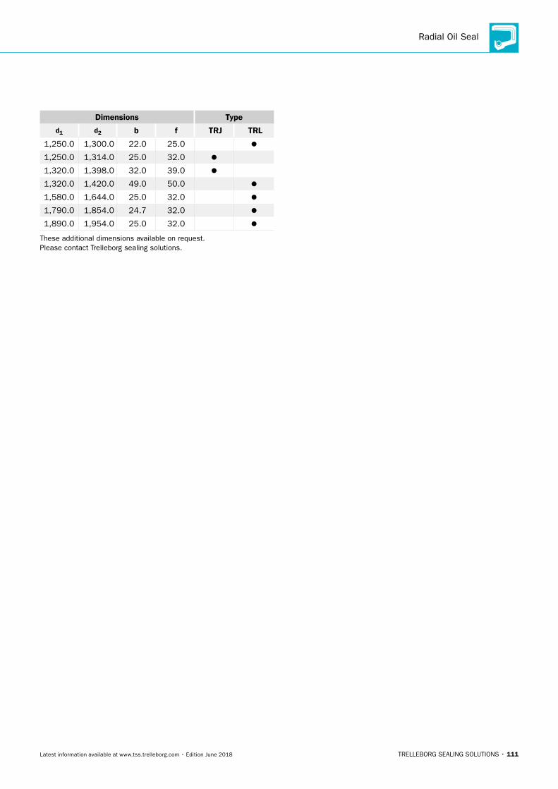
Radial Oil Seal
TRELLEBORG SEALING SOLUTIONS • 111Latest information available at www.tss.trelleborg.com • Edition June 2018
Dimensions Type
d1 d2 b f TRJ TRL
1,250.0 1,300.0 22.0 25.0
1,250.0 1,314.0 25.0 32.0
1,320.0 1,398.0 32.0 39.0
1,320.0 1,420.0 49.0 50.0
1,580.0 1,644.0 25.0 32.0
1,790.0 1,854.0 24.7 32.0
1,890.0 1,954.0 25.0 32.0
These additional dimensions available on request. Please contact Trelleborg sealing solutions.

ROTARY SEALS · Radial Oil Seal
112 • TRELLEBORG SEALING SOLUTIONS Latest information available at www.tss.trelleborg.com • Edition June 2018
TRELLEBORG SEALING SOLUTIONS • 113Latest information available at www.tss.trelleborg.com • Edition June 2018
Cassette Seal
ROTARY SEALS · Cassette Seal
114 • TRELLEBORG SEALING SOLUTIONS Latest information available at www.tss.trelleborg.com • Edition June 2018
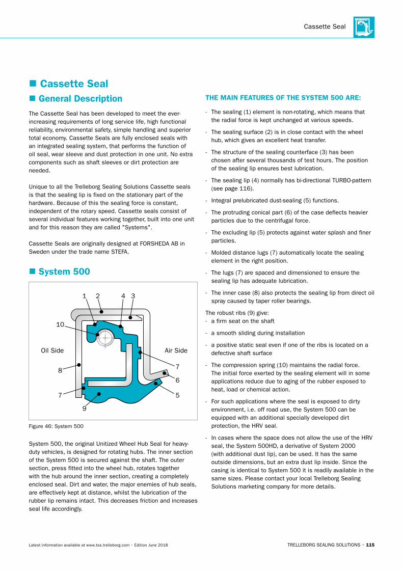
Cassette Seal
TRELLEBORG SEALING SOLUTIONS • 115Latest information available at www.tss.trelleborg.com • Edition June 2018
� Cassette Seal � General Description
The Cassette Seal has been developed to meet the ever-increasing requirements of long service life, high functional reliability, environmental safety, simple handling and superior total economy. Cassette Seals are fully enclosed seals with an integrated sealing system, that performs the function of oil seal, wear sleeve and dust protection in one unit. No extra components such as shaft sleeves or dirt protection are needed.
Unique to all the Trelleborg Sealing Solutions Cassette seals is that the sealing lip is fixed on the stationary part of the hardware. Because of this the sealing force is constant, independent of the rotary speed. Cassette seals consist of several individual features working together, built into one unit and for this reason they are called "Systems".
Cassette Seals are originally designed at FORSHEDA AB in Sweden under the trade name STEFA.
� System 500
Air SideOil Side
1 2 34
7
7
6
5
9
8
10
Figure 46: System 500
System 500, the original Unitized Wheel Hub Seal for heavy-duty vehicles, is designed for rotating hubs. The inner section of the System 500 is secured against the shaft. The outer section, press fitted into the wheel hub, rotates together with the hub around the inner section, creating a completely enclosed seal. Dirt and water, the major enemies of hub seals, are effectively kept at distance, whilst the lubrication of the rubber lip remains intact. This decreases friction and increases seal life accordingly.
THE MAIN FEATURES OF THE SYSTEM 500 ARE:
- The sealing (1) element is non-rotating, which means that the radial force is kept unchanged at various speeds.
- The sealing surface (2) is in close contact with the wheel hub, which gives an excellent heat transfer.
- The structure of the sealing counterface (3) has been chosen after several thousands of test hours. The position of the sealing lip ensures best lubrication.
- The sealing lip (4) normally has bi-directional TURBO-pattern (see page 116).
- Integral prelubricated dust-sealing (5) functions.
- The protruding conical part (6) of the case deflects heavier particles due to the centrifugal force.
- The excluding lip (5) protects against water splash and finer particles.
- Molded distance lugs (7) automatically locate the sealing element in the right position.
- The lugs (7) are spaced and dimensioned to ensure the sealing lip has adequate lubrication.
- The inner case (8) also protects the sealing lip from direct oil spray caused by taper roller bearings.
The robust ribs (9) give: - a firm seat on the shaft
- a smooth sliding during installation
- a positive static seal even if one of the ribs is located on a defective shaft surface
- The compression spring (10) maintains the radial force. The initial force exerted by the sealing element will in some applications reduce due to aging of the rubber exposed to heat, load or chemical action.
- For such applications where the seal is exposed to dirty environment, i.e. off road use, the System 500 can be equipped with an additional specially developed dirt protection, the HRV seal.
- In cases where the space does not allow the use of the HRV seal, the System 500HD, a derivative of System 2000 (with additional dust lip), can be used. It has the same outside dimensions, but an extra dust lip inside. Since the casing is identical to System 500 it is readily available in the same sizes. Please contact your local Trelleborg Sealing Solutions marketing company for more details.
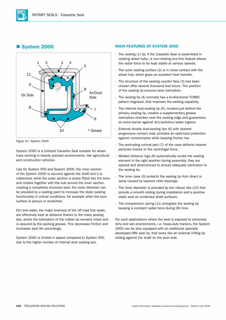
ROTARY SEALS · Cassette Seal
116 • TRELLEBORG SEALING SOLUTIONS Latest information available at www.tss.trelleborg.com • Edition June 2018
� System 2000
Air/DustSideOil Side
* Grease
1
11
9
8
3 2 45
*
* 7
8
6
10
Figure 47: System 2000
System 2000 is a Unitized Cassette Seal suitable for wheelhubs working in heavily polluted environments, like agricultural and construction vehicles.
Like for System 500 and System 3000, the inner section of the System 2000 is secured against the shaft and it is rubberized, while the outer section is press fitted into the bore, and rotates together with the hub around the inner section, creating a completely enclosed seal; the outer diameter can be provided by a sealing paint to increase the static sealing functionality in critical conditions, for example when the bore surface is porous or scratched.
Dirt and water, the major enemies of the off road hub seals, are effectively kept at distance thanks to the many sealing lips, whilst the lubrication of the rubber lip remains intact and is assured by the packing grease. This decreases friction and increases seal life accordingly.
System 2000 is limited in speed compared to System 500, due to the higher number of internal dust sealing lips.
MAIN FEATURES OF SYSTEM 2000
- The sealing (1) lip, if the Cassette Seal is assembled in rotating wheel hubs, is non-rotating and this feature allows the radial force to be kept stable at various speeds.
- The outer sealing surface (2) is in close contact with the wheel hub, which gives an excellent heat transfer.
- The structure of the sealing counter face (3) has been chosen after several thousand test hours. The position of the sealing lip ensures best lubrication.
- The sealing lip (4) normally has a bi-directional TURBO pattern engraved, that improves the sealing capability.
- The internal dust-sealing lip (5), located just behind the primary sealing lip, creates a supplementary grease lubrication chamber near the sealing edge and guarantees an extra barrier against dirt/pollution/water ingress
- External double dust-sealing lips (6) with tailored progressive contact load, provides an optimized protection against contaminants while keeping friction low.
- The protruding conical part (7) of the case deflects heavier particles thanks to the centrifugal force.
- Molded distance lugs (8) automatically locate the sealing element in the right position during assembly; they are spaced and dimensioned to ensure adequate lubrication to the sealing lip.
- The inner case (9) protects the sealing lip from direct oi spray caused by tapered roller bearings.
- The inner diameter is provided by two robust ribs (10) that provide a smooth sliding during installation and a positive static seal on scratched shaft surfaces.
- The compression spring (11) energizes the sealing lip keeping a constant radial force during life time.
For such applications where the seal is exposed to extremely dirty and wet environments, i.e. heavy-duty tractors, the System 2000 can be also equipped with an additional specially developed HRV seal lip, that looks like an external V-Ring lip sliding against the shaft on the dust side.
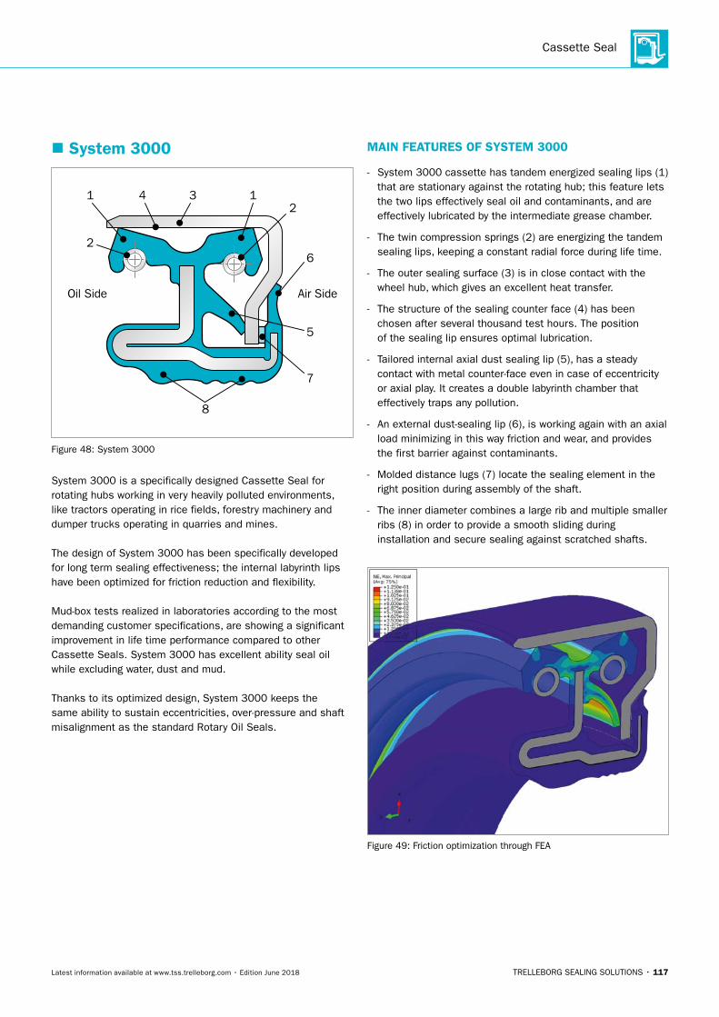
Cassette Seal
TRELLEBORG SEALING SOLUTIONS • 117Latest information available at www.tss.trelleborg.com • Edition June 2018
� System 3000
Air SideOil Side
1
2
4 3 12
5
6
7
8
Figure 48: System 3000
System 3000 is a specifically designed Cassette Seal for rotating hubs working in very heavily polluted environments, like tractors operating in rice fields, forestry machinery and dumper trucks operating in quarries and mines.
The design of System 3000 has been specifically developed for long term sealing effectiveness; the internal labyrinth lips have been optimized for friction reduction and flexibility.
Mud-box tests realized in laboratories according to the most demanding customer specifications, are showing a significant improvement in life time performance compared to other Cassette Seals. System 3000 has excellent ability seal oil while excluding water, dust and mud.
Thanks to its optimized design, System 3000 keeps the same ability to sustain eccentricities, over-pressure and shaft misalignment as the standard Rotary Oil Seals.
MAIN FEATURES OF SYSTEM 3000
- System 3000 cassette has tandem energized sealing lips (1) that are stationary against the rotating hub; this feature lets the two lips effectively seal oil and contaminants, and are effectively lubricated by the intermediate grease chamber.
- The twin compression springs (2) are energizing the tandem sealing lips, keeping a constant radial force during life time.
- The outer sealing surface (3) is in close contact with the wheel hub, which gives an excellent heat transfer.
- The structure of the sealing counter face (4) has been chosen after several thousand test hours. The position of the sealing lip ensures optimal lubrication.
- Tailored internal axial dust sealing lip (5), has a steady contact with metal counter-face even in case of eccentricity or axial play. It creates a double labyrinth chamber that effectively traps any pollution.
- An external dust-sealing lip (6), is working again with an axial load minimizing in this way friction and wear, and provides the first barrier against contaminants.
- Molded distance lugs (7) locate the sealing element in the right position during assembly of the shaft.
- The inner diameter combines a large rib and multiple smaller ribs (8) in order to provide a smooth sliding during installation and secure sealing against scratched shafts.
Figure 49: Friction optimization through FEA
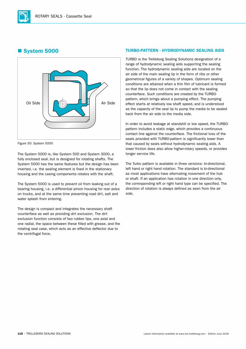
ROTARY SEALS · Cassette Seal
118 • TRELLEBORG SEALING SOLUTIONS Latest information available at www.tss.trelleborg.com • Edition June 2018
� System 5000
Air SideOil Side
Figure 50: System 5000
The System 5000 is, like System 500 and System 3000, a fully enclosed seal, but is designed for rotating shafts. The System 5000 has the same features but the design has been inverted, i.e. the sealing element is fixed in the stationary housing and the casing components rotates with the shaft.
The System 5000 is used to prevent oil from leaking out of a bearing housing, i.e. a differential pinion housing for rear axles on trucks, and at the same time preventing road dirt, salt and water splash from entering.
The design is compact and integrates the necessary shaft counterface as well as providing dirt exclusion. The dirt exclusion function consists of two rubber lips, one axial and one radial, the space between these filled with grease, and the rotating seal case, which acts as an effective deflector due to the centrifugal force.
TURBO-PATTERN - HYDRODYNAMIC SEALING AIDS
TURBO is the Trelleborg Sealing Solutions designation of a range of hydrodynamic sealing aids supporting the sealing function. The hydrodynamic sealing aids are located on the air side of the main sealing lip in the form of ribs or other geometrical figures of a variety of shapes. Optimum sealing conditions are attained when a thin film of lubricant is formed so that the lip does not come in contact with the sealing counterface. Such conditions are created by the TURBO-pattern, which brings about a pumping effect. The pumping effect starts at relatively low shaft speed, and is understood as the capacity of the seal lip to pump the media to be sealed back from the air side to the media side.
In order to avoid leakage at standstill or low speed, the TURBO-pattern includes a static edge, which provides a continuous contact line against the counterface. The frictional loss of the seals provided with TURBO-pattern is significantly lower than that caused by seals without hydrodynamic sealing aids. A lower friction does also allow higher-rotary speeds, or provides longer service life.
The Turbo pattern is available in three versions: bi-directional, left hand or right hand rotation. The standard is bi-directional as most applications have alternating movement of the hub or shaft. If an application has rotation in one direction only, the corresponding left or right hand type can be specified. The direction of rotation is always defined as seen from the air side.
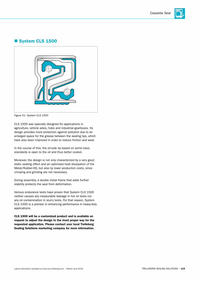
Cassette Seal
TRELLEBORG SEALING SOLUTIONS • 119Latest information available at www.tss.trelleborg.com • Edition June 2018
� System CLS 1500
Figure 51: System CLS 1500
CLS 1500 was specially designed for applications in agriculture, vehicle axles, hubs and industrial gearboxes. Its design provides more protection against pollution due to an enlarged space for the grease between the sealing lips, which have also been improved in order to reduce friction and wear.
In the course of this, the oil-side lip based on world class standards is open to the oil and thus better cooled.
Moreover, the design is not only characterized by a very good static sealing effect and an optimized heat dissipation of the Metal/Rubber-OD, but also by lower production costs, since crimping and grinding are not necessary.
During assembly, a double metal frame that adds further stability protects the seal from deformation.
Various endurance tests have proven that System CLS 1500 neither causes any measurable leakage in hot oil tests nor any oil contamination in slurry tests. For that reason, System CLS 1500 is a pioneer in enhancing performance in heavy-duty applications.
CLS 1500 will be a customized product and is available on request to adjust the design to the most proper way for the requested application. Please contact your local Trelleborg Sealing Solutions marketing company for more information.
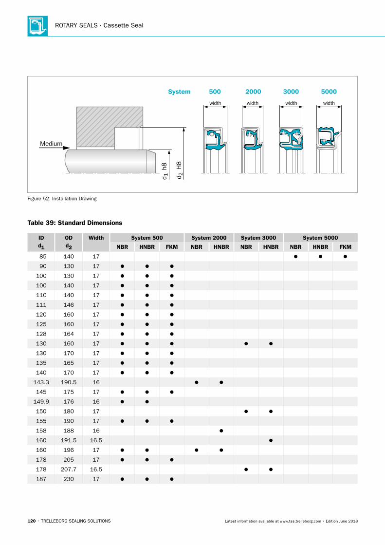
ROTARY SEALS · Cassette Seal
120 • TRELLEBORG SEALING SOLUTIONS Latest information available at www.tss.trelleborg.com • Edition June 2018
System
d 2 H
8
d 1 h
8
Medium
5000
width
3000
width
500
width
2000
width
Figure 52: Installation Drawing
Table 39: Standard Dimensions
IDd1
ODd2
Width System 500 System 2000 System 3000 System 5000
NBR HNBR FKM NBR HNBR NBR HNBR NBR HNBR FKM
85 140 17
90 130 17
100 130 17
100 140 17
110 140 17
111 146 17
120 160 17
125 160 17
128 164 17
130 160 17
130 170 17
135 165 17
140 170 17
143.3 190.5 16
145 175 17
149.9 176 16
150 180 17
155 190 17
158 188 16
160 191.5 16.5
160 196 17
178 205 17
178 207.7 16.5
187 230 17
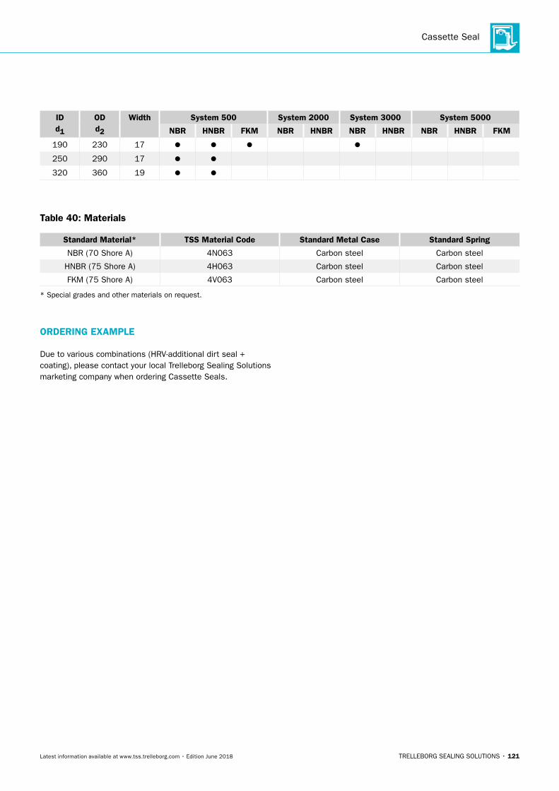
Cassette Seal
TRELLEBORG SEALING SOLUTIONS • 121Latest information available at www.tss.trelleborg.com • Edition June 2018
IDd1
ODd2
Width System 500 System 2000 System 3000 System 5000
NBR HNBR FKM NBR HNBR NBR HNBR NBR HNBR FKM
190 230 17
250 290 17
320 360 19
Table 40: Materials
Standard Material* TSS Material Code Standard Metal Case Standard Spring
NBR (70 Shore A) 4N063 Carbon steel Carbon steel
HNBR (75 Shore A) 4H063 Carbon steel Carbon steel
FKM (75 Shore A) 4V063 Carbon steel Carbon steel
* Special grades and other materials on request.
ORDERING EXAMPLE
Due to various combinations (HRV-additional dirt seal + coating), please contact your local Trelleborg Sealing Solutions marketing company when ordering Cassette Seals.
ROTARY SEALS · Cassette Seal
122 • TRELLEBORG SEALING SOLUTIONS Latest information available at www.tss.trelleborg.com • Edition June 2018
� Materials
METAL CASE
The cases are normally stamped of cold rolled steel sheet, EN 10 130 - Fe P04. The high demands on the metal cases; high surface finish, free from scratches etc., calls for production using special tools.
COMPRESSION SPRING
For the spring, spring steel SS14 1774 - DIN 17223 - is normally employed. If resistance to corrosion is required, stainless steel SS 14 2331 - DIN 1.4301 is used.
SEALING ELEMENT
The material of the sealing element must be selected according to the working conditions of the seal and the environmental conditions.
Some of the requirements associated with environmental considerations are:
- good chemical resistance
- good resistance to heat and low temperature
- good resistance to ozone and weathering
The functional demands include:
- high resistance to wear
- low friction
- low compression set
- good elasticity
In addition, cost considerations make ease of processing a desirable feature.
No material is available today, which satisfies all these requirements. The choice of material is therefore always a compromise between the relative significance of the factors involved.
Trelleborg Sealing Solutions has succeeded in developing a Nitrile Rubber compound (NBR), which exhibits good all-round properties, and for this reason is the compound most commonly used.
The materials normally used for the sealing element are:Nitrile Rubber (NBR), Hydrogenated Nitrile Rubber (HNBR) and Fluorinated Elastomers (FKM).
The additional dirt seal is normally made of Nitrile Rubber.Nitrile Rubber is the basis material for Cassette Seals, as it covers most standard application requirements for general oil- and grease resistance. It is from function and cost aspects the best choice when temperature is not excessively high.Nitrile can be used up to +125 °C in non-aggressive oils. However for long term use, or in aggressive oils, service temperature is reduced to +80 °C.
Nitrile generally has good mechanical properties and the material used for Cassette Seals is optimized for best heat and abrasion resistance.
Hydrogenated Nitrile Rubber is a further development of NBR, where the chemical double bonds in the polymer molecules are saturated with hydrogen. Since the double bonds of NBR are sensitive to heat and ozone, the HNBR will be superior to NBR in heat, ozone and weather resistance. It can generally be used up to +150 °C in non-aggressive media, however for long term use maximum service temperature is +120 °C.
The HNBR for the Cassette Seal is fully saturated and thus well suited for use in aggressive oils. The temperature should however be limited at +120 °C. As saturated HNBR cannot be vulcanized with sulfur, the material has resistance to most hypoid oils up to about +120 °C for long term use.
Low friction and high abrasion resistance are additional typical features.
Fluorinated elastomers give peak performance regarding heat and chemical resistance. They can be used up to +200 °C for long term use and are generally very resistant to oil, grease and fuels. Their ozone and weather resistance is outstanding.
Mechanical and low temperature properties are however lower compared to Nitrile. Thus Fluoroelastomers should be considered only when the material properties are fully used. Some oil additives like amines and high pH-values may damage Fluoroelastomers when used at high temperatures.
TEMPERATURE RESISTANCE
Increasing temperature accelerates the aging of rubber, the elongation decreases, and the compression set increases and finally the material becomes hard and brittle. Cracks at the sealing edge are a typical indication that the seal has been exposed to excessively high temperature. The aging of the rubber has appreciable significance on the useful life of the seal. It can generally be said that a temperature increase of +10 °C (in air) will half the theoretical useful life of the rubber.
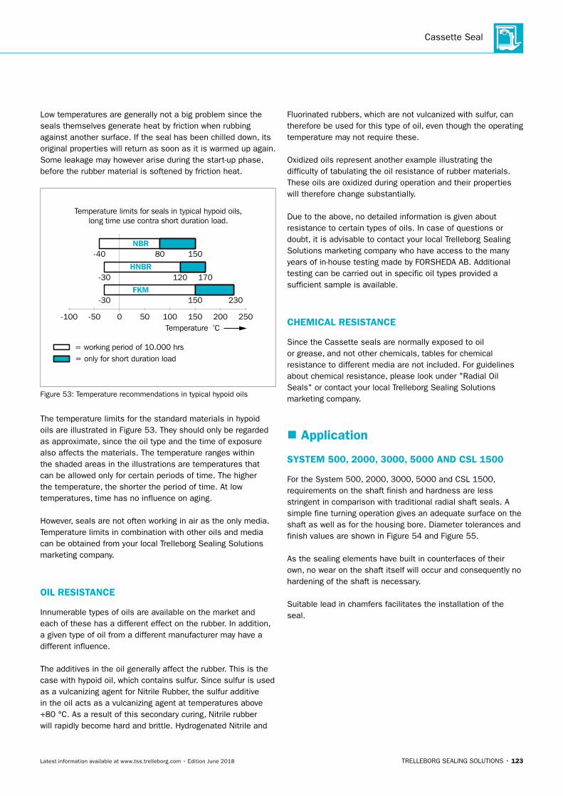
Cassette Seal
TRELLEBORG SEALING SOLUTIONS • 123Latest information available at www.tss.trelleborg.com • Edition June 2018
Low temperatures are generally not a big problem since the seals themselves generate heat by friction when rubbing against another surface. If the seal has been chilled down, its original properties will return as soon as it is warmed up again. Some leakage may however arise during the start-up phase, before the rubber material is softened by friction heat.
Temperature limits for seals in typical hypoid oils,long time use contra short duration load.
Temperature ºC
= only for short duration load= working period of 10.000 hrs
-40 80 150
170120-30
-30 150 230
25015050 100 2000-50-100
NBR
HNBR
FKM
Figure 53: Temperature recommendations in typical hypoid oils
The temperature limits for the standard materials in hypoid oils are illustrated in Figure 53. They should only be regarded as approximate, since the oil type and the time of exposure also affects the materials. The temperature ranges within the shaded areas in the illustrations are temperatures that can be allowed only for certain periods of time. The higher the temperature, the shorter the period of time. At low temperatures, time has no influence on aging.
However, seals are not often working in air as the only media. Temperature limits in combination with other oils and media can be obtained from your local Trelleborg Sealing Solutions marketing company.
OIL RESISTANCE
Innumerable types of oils are available on the market and each of these has a different effect on the rubber. In addition, a given type of oil from a different manufacturer may have a different influence.
The additives in the oil generally affect the rubber. This is the case with hypoid oil, which contains sulfur. Since sulfur is used as a vulcanizing agent for Nitrile Rubber, the sulfur additive in the oil acts as a vulcanizing agent at temperatures above +80 °C. As a result of this secondary curing, Nitrile rubber will rapidly become hard and brittle. Hydrogenated Nitrile and
Fluorinated rubbers, which are not vulcanized with sulfur, can therefore be used for this type of oil, even though the operating temperature may not require these.
Oxidized oils represent another example illustrating the difficulty of tabulating the oil resistance of rubber materials. These oils are oxidized during operation and their properties will therefore change substantially.
Due to the above, no detailed information is given about resistance to certain types of oils. In case of questions or doubt, it is advisable to contact your local Trelleborg Sealing Solutions marketing company who have access to the many years of in-house testing made by FORSHEDA AB. Additional testing can be carried out in specific oil types provided a sufficient sample is available.
CHEMICAL RESISTANCE
Since the Cassette seals are normally exposed to oil or grease, and not other chemicals, tables for chemical resistance to different media are not included. For guidelines about chemical resistance, please look under "Radial Oil Seals" or contact your local Trelleborg Sealing Solutions marketing company.
� Application
SYSTEM 500, 2000, 3000, 5000 AND CSL 1500
For the System 500, 2000, 3000, 5000 and CSL 1500, requirements on the shaft finish and hardness are less stringent in comparison with traditional radial shaft seals. A simple fine turning operation gives an adequate surface on the shaft as well as for the housing bore. Diameter tolerances and finish values are shown in Figure 54 and Figure 55.
As the sealing elements have built in counterfaces of their own, no wear on the shaft itself will occur and consequently no hardening of the shaft is necessary.
Suitable lead in chamfers facilitates the installation of the seal.
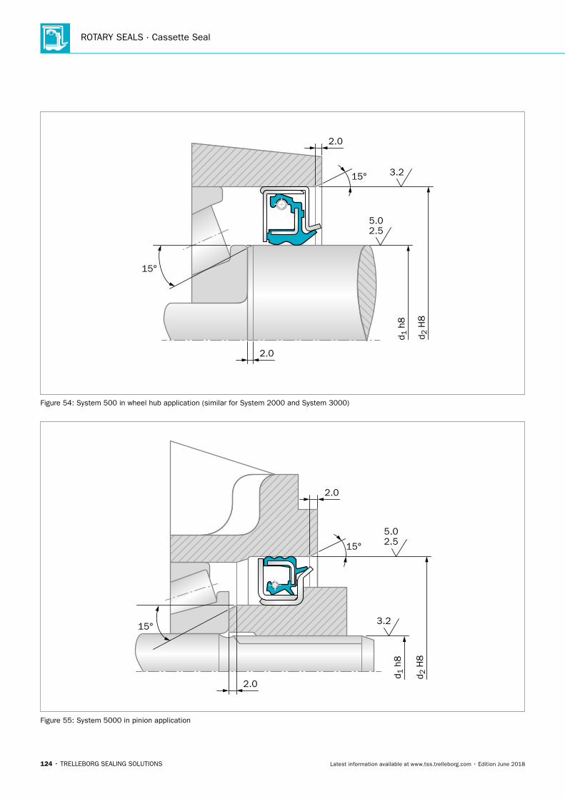
ROTARY SEALS · Cassette Seal
124 • TRELLEBORG SEALING SOLUTIONS Latest information available at www.tss.trelleborg.com • Edition June 2018
2.0
d 1 h
8
15°
15°
2.0
2.55.0
3.2
d 2 H
8
Figure 54: System 500 in wheel hub application (similar for System 2000 and System 3000)d 1
h8
2.0
2.55.0
2.0
15° 3.2
d 2 H
8
15°
Figure 55: System 5000 in pinion application
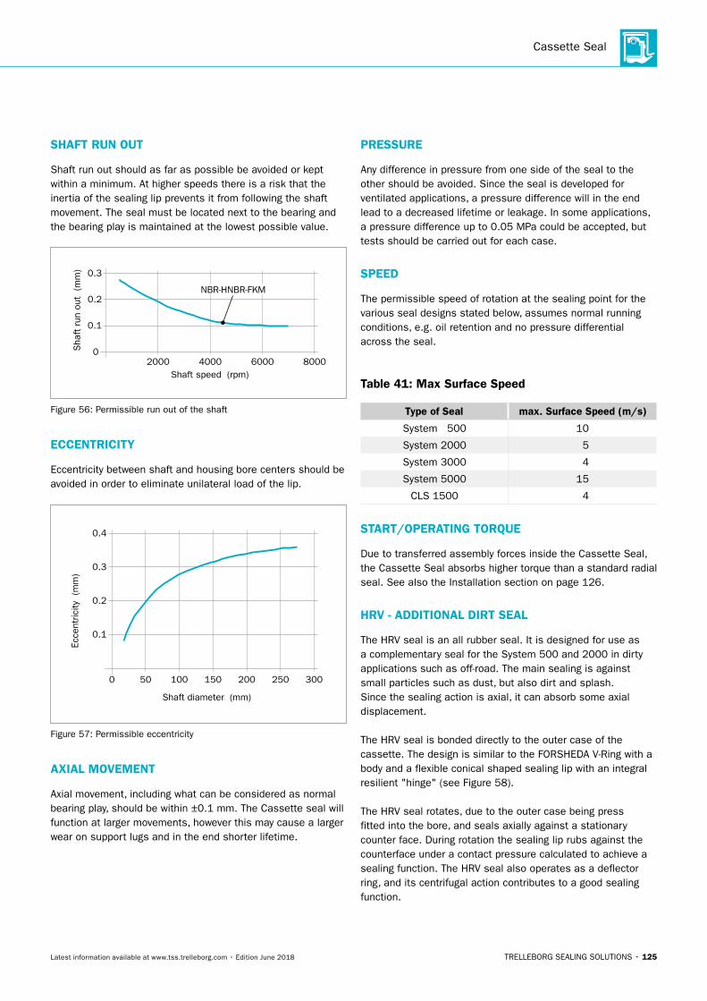
Cassette Seal
TRELLEBORG SEALING SOLUTIONS • 125Latest information available at www.tss.trelleborg.com • Edition June 2018
SHAFT RUN OUT
Shaft run out should as far as possible be avoided or kept within a minimum. At higher speeds there is a risk that the inertia of the sealing lip prevents it from following the shaft movement. The seal must be located next to the bearing and the bearing play is maintained at the lowest possible value.
Shaft speed (rpm)
02000 4000 6000 8000
0.1
0.2
0.3
Sha
ft r
un o
ut
(mm
)
NBR-HNBR-FKM
Figure 56: Permissible run out of the shaft
ECCENTRICITY
Eccentricity between shaft and housing bore centers should be avoided in order to eliminate unilateral load of the lip.
Shaft diameter (mm)
Ecce
ntric
ity (m
m)
0
0.1
0.2
0.3
0.4
50 100 150 200 250 300
Figure 57: Permissible eccentricity
AXIAL MOVEMENT
Axial movement, including what can be considered as normal bearing play, should be within ±0.1 mm. The Cassette seal will function at larger movements, however this may cause a larger wear on support lugs and in the end shorter lifetime.
PRESSURE
Any difference in pressure from one side of the seal to the other should be avoided. Since the seal is developed for ventilated applications, a pressure difference will in the end lead to a decreased lifetime or leakage. In some applications, a pressure difference up to 0.05 MPa could be accepted, but tests should be carried out for each case.
SPEED
The permissible speed of rotation at the sealing point for the various seal designs stated below, assumes normal running conditions, e.g. oil retention and no pressure differential across the seal.
Table 41: Max Surface Speed
Type of Seal max. Surface Speed (m/s)
System 500 10
System 2000 5
System 3000 4
System 5000 15
CLS 1500 4
START/OPERATING TORQUE
Due to transferred assembly forces inside the Cassette Seal, the Cassette Seal absorbs higher torque than a standard radial seal. See also the Installation section on page 126.
HRV - ADDITIONAL DIRT SEAL
The HRV seal is an all rubber seal. It is designed for use as a complementary seal for the System 500 and 2000 in dirty applications such as off-road. The main sealing is against small particles such as dust, but also dirt and splash. Since the sealing action is axial, it can absorb some axial displacement.
The HRV seal is bonded directly to the outer case of the cassette. The design is similar to the FORSHEDA V-Ring with a body and a flexible conical shaped sealing lip with an integral resilient "hinge" (see Figure 58).
The HRV seal rotates, due to the outer case being press fitted into the bore, and seals axially against a stationary counter face. During rotation the sealing lip rubs against the counterface under a contact pressure calculated to achieve a sealing function. The HRV seal also operates as a deflector ring, and its centrifugal action contributes to a good sealing function.
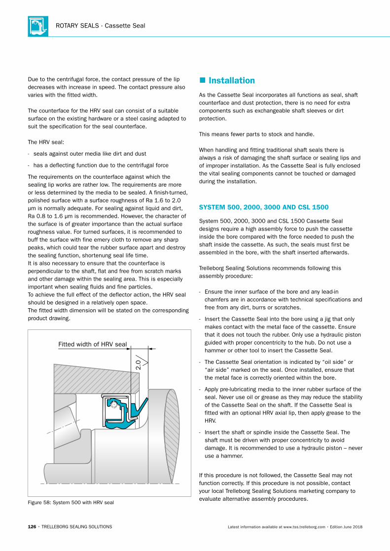
ROTARY SEALS · Cassette Seal
126 • TRELLEBORG SEALING SOLUTIONS Latest information available at www.tss.trelleborg.com • Edition June 2018
Due to the centrifugal force, the contact pressure of the lip decreases with increase in speed. The contact pressure also varies with the fitted width.
The counterface for the HRV seal can consist of a suitable surface on the existing hardware or a steel casing adapted to suit the specification for the seal counterface.
The HRV seal:
- seals against outer media like dirt and dust
- has a deflecting function due to the centrifugal force
The requirements on the counterface against which the sealing lip works are rather low. The requirements are more or less determined by the media to be sealed. A finish-turned, polished surface with a surface roughness of Ra 1.6 to 2.0 μm is normally adequate. For sealing against liquid and dirt, Ra 0.8 to 1.6 μm is recommended. However, the character of the surface is of greater importance than the actual surface roughness value. For turned surfaces, it is recommended to buff the surface with fine emery cloth to remove any sharp peaks, which could tear the rubber surface apart and destroy the sealing function, shortenung seal life time.It is also necessary to ensure that the counterface is perpendicular to the shaft, flat and free from scratch marks and other damage within the sealing area. This is especially important when sealing fluids and fine particles.To achieve the full effect of the deflector action, the HRV seal should be designed in a relatively open space.The fitted width dimension will be stated on the corresponding product drawing.
Fitted width of HRV seal
2.0
Figure 58: System 500 with HRV seal
� InstallationAs the Cassette Seal incorporates all functions as seal, shaft counterface and dust protection, there is no need for extra components such as exchangeable shaft sleeves or dirt protection.
This means fewer parts to stock and handle.
When handling and fitting traditional shaft seals there is always a risk of damaging the shaft surface or sealing lips and of improper installation. As the Cassette Seal is fully enclosed the vital sealing components cannot be touched or damaged during the installation.
SYSTEM 500, 2000, 3000 AND CSL 1500
System 500, 2000, 3000 and CSL 1500 Cassette Seal designs require a high assembly force to push the cassette inside the bore compared with the force needed to push the shaft inside the cassette. As such, the seals must first be assembled in the bore, with the shaft inserted afterwards. Trelleborg Sealing Solutions recommends following this assembly procedure:
- Ensure the inner surface of the bore and any lead-in chamfers are in accordance with technical specifications and free from any dirt, burrs or scratches.
- Insert the Cassette Seal into the bore using a jig that only makes contact with the metal face of the cassette. Ensure that it does not touch the rubber. Only use a hydraulic piston guided with proper concentricity to the hub. Do not use a hammer or other tool to insert the Cassette Seal.
- The Cassette Seal orientation is indicated by “oil side” or “air side” marked on the seal. Once installed, ensure that the metal face is correctly oriented within the bore.
- Apply pre-lubricating media to the inner rubber surface of the seal. Never use oil or grease as they may reduce the stability of the Cassette Seal on the shaft. If the Cassette Seal is fitted with an optional HRV axial lip, then apply grease to the HRV.
- Insert the shaft or spindle inside the Cassette Seal. The shaft must be driven with proper concentricity to avoid damage. It is recommended to use a hydraulic piston – never use a hammer.
If this procedure is not followed, the Cassette Seal may not function correctly. If this procedure is not possible, contact your local Trelleborg Sealing Solutions marketing company to evaluate alternative assembly procedures.
Cassette Seal
TRELLEBORG SEALING SOLUTIONS • 127Latest information available at www.tss.trelleborg.com • Edition June 2018
During the start-up phase with the new Cassette Seal, some leakage of grease and smoke formation may be observed. This is a result of the generation of frictional heat between the metal case and internal rubber support lugs, and does not influence the function and service life of the seal. When repairing or replacing a Cassette seal, always use a new seal.
SYSTEM 5000
The System 5000 seal must be installed onto a shaft or a sleeve by a special assembly tool. The seal shall be oriented with the side marked "oil side" facing the inside of the gearbox. The shaft must then be assembled so the oil side of the seal is entering the housing bore.
If the shaft is hollow, the assembly tool should be designed with a guiding column.
For pinion applications on trucks, when a separate end carrier is used, the seal is simply pressed onto the end carrier in a first step of assembling. The end carrier is then entering the splines on the pinion shaft and then a locking nut is used to drive the end carrier and the seal into the right position.
The force required to assemble a System 5000 seal onto the shaft is between 20 to 50 kN, while assembly into the housing bore requires about 1.0 kN. The value of assembly force depends on the surface structure for shaft respecting the housing bore as well as the tolerances. It is recommended to oil the outer rubber covered surface of the seal and also the housing bore, to decrease the force necessary for assembly.
During the start-up phase, eventually some leakage of grease and smoke formation may occur. This is a result of the generation of frictional heat between the metal cases and the support lugs of rubber, and does not influence on the function and service life of the seal.
If the seal is jammed or damaged in some way during installation, the seal must be replaced before start up.
If the construction is disassembled for any reason, a new seal should be installed.
Further instructions for assembling can be found on separate assembly instruction sheets available from your local Trelleborg Sealing Solutions marketing company.
DISMANTLING AND REPLACEMENT
As all the necessary functions are integrated in the Cassette Seal the complete sealing arrangement is renewed. The shaft to be sealed is unaffected by wear and once it has been cleaned and possible corrosion and dirt have been removed a new seal can be fitted again.The Cassette Seal may be provided with a sealant on the metal casing when it is installed into the housing. Take care that the sealant does not flow into the seal or is smeared onto the rubber surface, as this may impede the function of the seal. The sealant can reduce the risk of static leakage due to small imperfections on the surface.
STORAGE
As the service life of bearings and other machine parts depends on how well the seals perform, seals should be handled with caution. Unfavorable storage conditions or improper handling will most likely lead to a change of their physical properties. This can lead to a shortening of life, or failure, for example as a result of hardening or softening, cracking or other surface damages. These changes can be the result of one particular factor or a combination of factors, like oxygen, ozone, heat, light, moisture, solvents etc. Storing the seals under load can lead to permanent deformation of the elastomer. On the other hand, properly stored elastomer products retain their properties for several years.
As the sensitive sealing lips and counter faces are well protected inside the Cassette Seal casing, there is less risk of mechanical damages and influence of dirt and dust in comparison to many other seal types.
CLEANING
If cleaning of Cassette Seal is necessary, use a damp duster and allow the seals to dry off at room temperature.
Solvents, sharp-edged objects and abrasives should not be used.
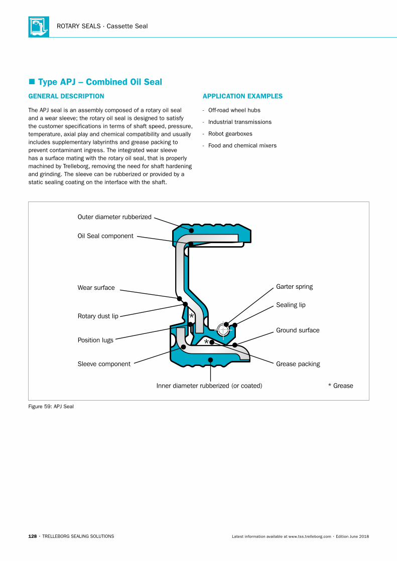
ROTARY SEALS · Cassette Seal
128 • TRELLEBORG SEALING SOLUTIONS Latest information available at www.tss.trelleborg.com • Edition June 2018
� Type APJ – Combined Oil Seal GENERAL DESCRIPTION
The APJ seal is an assembly composed of a rotary oil seal and a wear sleeve; the rotary oil seal is designed to satisfy the customer specifications in terms of shaft speed, pressure, temperature, axial play and chemical compatibility and usually includes supplementary labyrinths and grease packing to prevent contaminant ingress. The integrated wear sleeve has a surface mating with the rotary oil seal, that is properly machined by Trelleborg, removing the need for shaft hardening and grinding. The sleeve can be rubberized or provided by a static sealing coating on the interface with the shaft.
APPLICATION EXAMPLES
- Off-road wheel hubs
- Industrial transmissions
- Robot gearboxes
- Food and chemical mixers
Outer diameter rubberized
Oil Seal component
Wear surface
Rotary dust lip
Position lugs
Sleeve component
Inner diameter rubberized (or coated)
Grease packing
Sealing lip
Garter spring
Ground surface
*
*
* Grease
Figure 59: APJ Seal
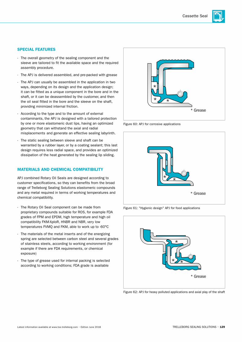
Cassette Seal
TRELLEBORG SEALING SOLUTIONS • 129Latest information available at www.tss.trelleborg.com • Edition June 2018
SPECIAL FEATURES
- The overall geometry of the sealing component and the sleeve are tailored to fit the available space and the required assembly procedure.
- The APJ is delivered assembled, and pre-packed with grease
- The APJ can usually be assembled in the application in two ways, depending on its design and the application design; it can be fitted as a unique component in the bore and in the shaft, or it can be deassembled by the customer, and then the oil seal fitted in the bore and the sleeve on the shaft, providing minimized internal friction.
- According to the type and to the amount of external contaminants, the APJ is designed with a tailored protection by one or more elastomeric dust lips, having an optimized geometry that can withstand the axial and radial misplacements and generate an effective sealing labyrinth.
- The static sealing between sleeve and shaft can be warranted by a rubber layer, or by a coating sealant; this last design requires less radial space, and provides an optimized dissipation of the heat generated by the sealing lip sliding.
MATERIALS AND CHEMICAL COMPATIBILITY
APJ combined Rotary Oil Seals are designed according to customer specifications, so they can benefits from the broad range of Trelleborg Sealing Solutions elastomeric compounds and any metal required in terms of working temperatures and chemical compatibility.
- The Rotary Oil Seal component can be made from proprietary compounds suitable for ROS, for example FDA grades of FPM and EPDM, high temperature and high oil compatibility FKM-XploR, HNBR and NBR, very low temperatures FVMQ and FKM, able to work up to -60°C
- The materials of the metal inserts and of the energizing spring are selected between carbon steel and several grades of stainless steels, according to working environment (for example if there are FDA requirements, or chemical exposure)
- The type of grease used for internal packing is selected according to working conditions; FDA grade is available
*
* *
* *
*
*
*
* Grease
* Grease
* Grease
Figure 60: APJ for corrosive applications
*
* *
* *
*
*
*
* Grease
* Grease
* Grease
Figure 61: "Hygienic design" APJ for food applications
*
* *
* *
*
*
*
* Grease
* Grease
* Grease
Figure 62: APJ for heavy polluted applications and axial play of the shaft

ROTARY SEALS · Cassette Seal
130 • TRELLEBORG SEALING SOLUTIONS Latest information available at www.tss.trelleborg.com • Edition June 2018
TRELLEBORG SEALING SOLUTIONS • 131Latest information available at www.tss.trelleborg.com • Edition June 2018
End Covers
ROTARY SEALS · End Covers
132 • TRELLEBORG SEALING SOLUTIONS Latest information available at www.tss.trelleborg.com • Edition June 2018
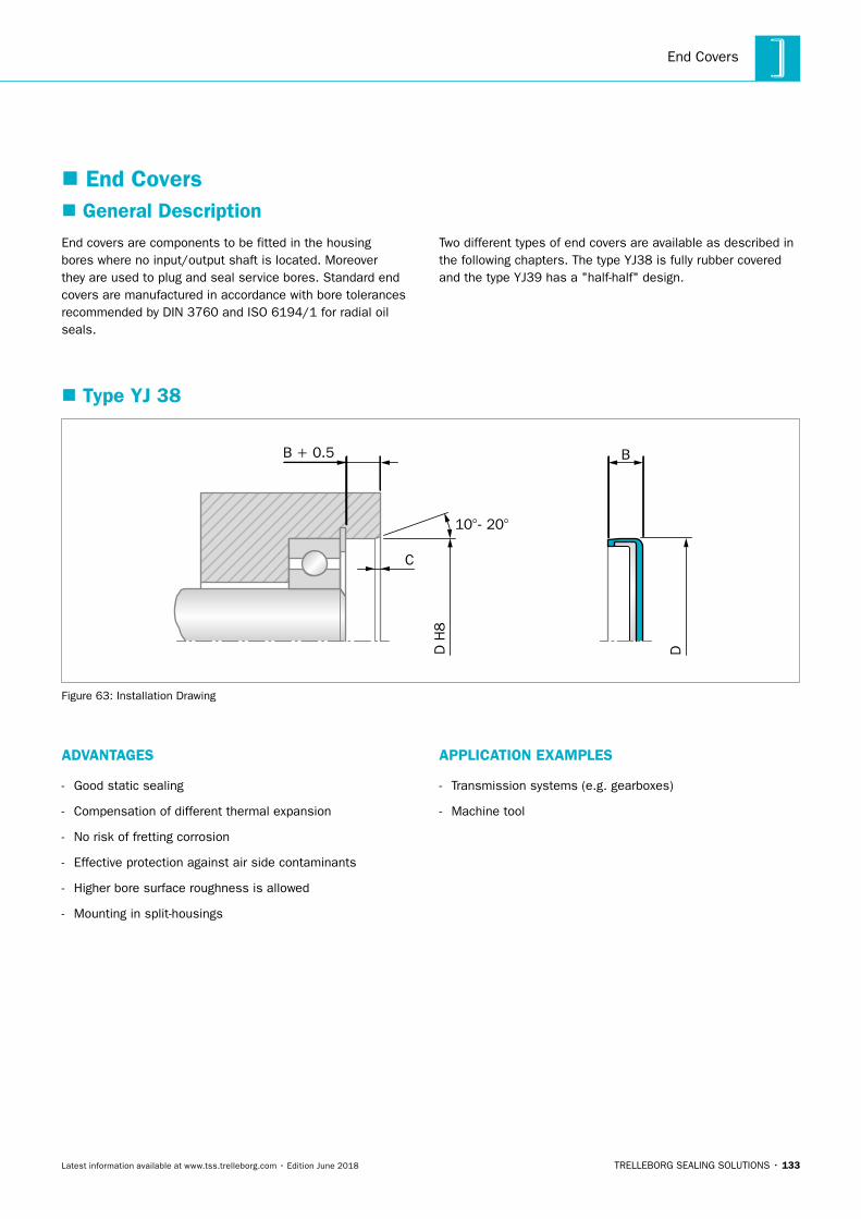
End Covers
TRELLEBORG SEALING SOLUTIONS • 133Latest information available at www.tss.trelleborg.com • Edition June 2018
� End Covers
End covers are components to be fitted in the housing bores where no input/output shaft is located. Moreover they are used to plug and seal service bores. Standard end covers are manufactured in accordance with bore tolerances recommended by DIN 3760 and ISO 6194/1 for radial oil seals.
Two different types of end covers are available as described in the following chapters. The type YJ38 is fully rubber covered and the type YJ39 has a "half-half" design.
� Type YJ 38
D H
8
C
10°- 20°
B + 0.5 B
DFigure 63: Installation Drawing
� General Description
ADVANTAGES
- Good static sealing
- Compensation of different thermal expansion
- No risk of fretting corrosion
- Effective protection against air side contaminants
- Higher bore surface roughness is allowed
- Mounting in split-housings
APPLICATION EXAMPLES
- Transmission systems (e.g. gearboxes)
- Machine tool
ROTARY SEALS · End Covers
134 • TRELLEBORG SEALING SOLUTIONS Latest information available at www.tss.trelleborg.com • Edition June 2018
OPERATING CONDITIONS
Pressure: Up to 0.05 MPa
Temperature: -40 °C to +200 °C depending on material
Media: Mineral and synthetic lubricants (CLP, HLP, APGL etc.)
Trelleborg Sealing Solutions has carried out several thousands compatibility tests. Please ask for details.
IMPORTANT NOTE
The above data are maximum values and cannot be used at the same time, e. g. the maximum operating speed depends on material type, pressure and temperature.
ORDERING EXAMPLE END COVER TSS TYPE
TSS Type: YJ
Code: YJ38
Dimensions: Housing diameter 50 mmWidth 10 mm
Material: NBR
Material Code: N7MMN
Trelleborg Sealing Solutions has carried out several thousand compatibility tests. Please ask your local Trelleborg Sealing Solutions marketing company for details.
N7MMN
Material Code (Standard)
CodeTSS Article No. -
Shaft Diameter x 10Quality Index (Standard)
YJ38
Execution
05000
Table 42: Materials
Standard Material* TSS Material Code Standard Metal Insert**
NBR (70 Shore A) N7MMN Carbon steel
NBR (75 Shore A) 4N01 Carbon steel
FKM (75 Shore A) VCBV Carbon steel
FKM (75 Shore A) 4V01 Carbon steel
* Special grades and other materials (ACM, EACM, EPDM, HNBR, VMQ) on request. ** Metal insert can also be supplied in different materials on request
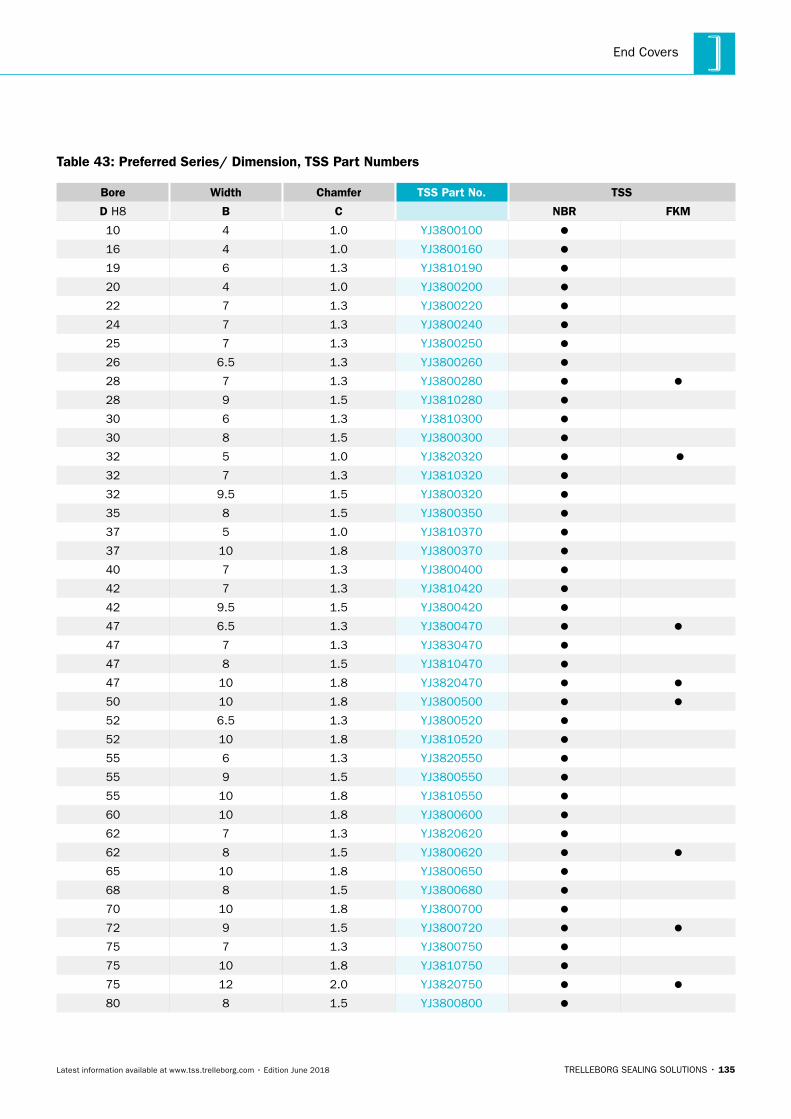
End Covers
TRELLEBORG SEALING SOLUTIONS • 135Latest information available at www.tss.trelleborg.com • Edition June 2018
Table 43: Preferred Series/ Dimension, TSS Part Numbers
Bore Width Chamfer TSS Part No. TSS
D H8 B C NBR FKM
10 4 1.0 YJ3800100
16 4 1.0 YJ3800160
19 6 1.3 YJ3810190
20 4 1.0 YJ3800200
22 7 1.3 YJ3800220
24 7 1.3 YJ3800240
25 7 1.3 YJ3800250
26 6.5 1.3 YJ3800260
28 7 1.3 YJ3800280
28 9 1.5 YJ3810280
30 6 1.3 YJ3810300
30 8 1.5 YJ3800300
32 5 1.0 YJ3820320
32 7 1.3 YJ3810320
32 9.5 1.5 YJ3800320
35 8 1.5 YJ3800350
37 5 1.0 YJ3810370
37 10 1.8 YJ3800370
40 7 1.3 YJ3800400
42 7 1.3 YJ3810420
42 9.5 1.5 YJ3800420
47 6.5 1.3 YJ3800470
47 7 1.3 YJ3830470
47 8 1.5 YJ3810470
47 10 1.8 YJ3820470
50 10 1.8 YJ3800500
52 6.5 1.3 YJ3800520
52 10 1.8 YJ3810520
55 6 1.3 YJ3820550
55 9 1.5 YJ3800550
55 10 1.8 YJ3810550
60 10 1.8 YJ3800600
62 7 1.3 YJ3820620
62 8 1.5 YJ3800620
65 10 1.8 YJ3800650
68 8 1.5 YJ3800680
70 10 1.8 YJ3800700
72 9 1.5 YJ3800720
75 7 1.3 YJ3800750
75 10 1.8 YJ3810750
75 12 2.0 YJ3820750
80 8 1.5 YJ3800800
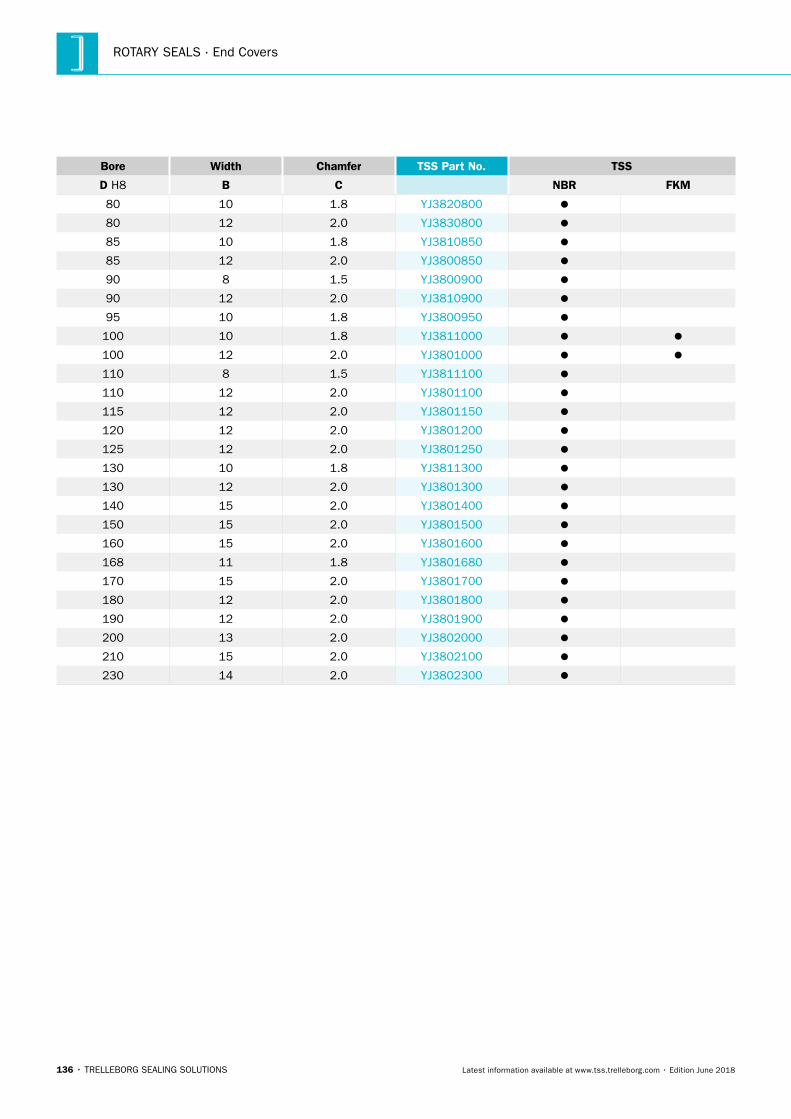
ROTARY SEALS · End Covers
136 • TRELLEBORG SEALING SOLUTIONS Latest information available at www.tss.trelleborg.com • Edition June 2018
Bore Width Chamfer TSS Part No. TSS
D H8 B C NBR FKM
80 10 1.8 YJ3820800
80 12 2.0 YJ3830800
85 10 1.8 YJ3810850
85 12 2.0 YJ3800850
90 8 1.5 YJ3800900
90 12 2.0 YJ3810900
95 10 1.8 YJ3800950
100 10 1.8 YJ3811000
100 12 2.0 YJ3801000
110 8 1.5 YJ3811100
110 12 2.0 YJ3801100
115 12 2.0 YJ3801150
120 12 2.0 YJ3801200
125 12 2.0 YJ3801250
130 10 1.8 YJ3811300
130 12 2.0 YJ3801300
140 15 2.0 YJ3801400
150 15 2.0 YJ3801500
160 15 2.0 YJ3801600
168 11 1.8 YJ3801680
170 15 2.0 YJ3801700
180 12 2.0 YJ3801800
190 12 2.0 YJ3801900
200 13 2.0 YJ3802000
210 15 2.0 YJ3802100
230 14 2.0 YJ3802300
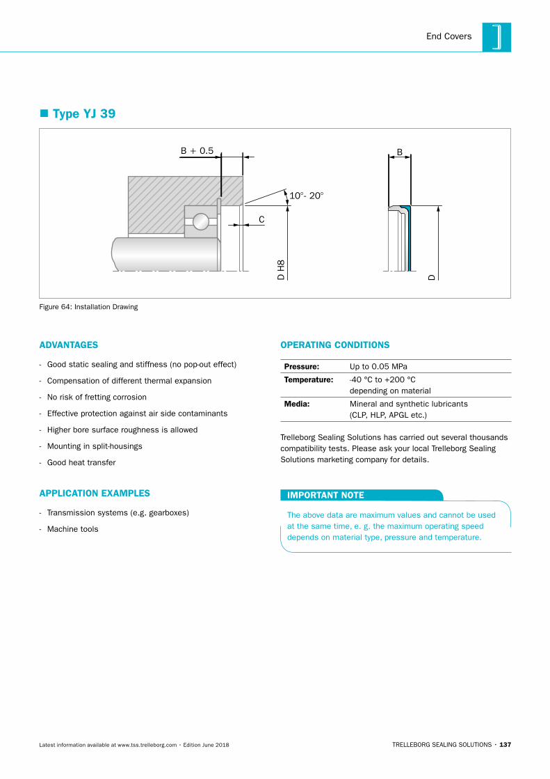
End Covers
TRELLEBORG SEALING SOLUTIONS • 137Latest information available at www.tss.trelleborg.com • Edition June 2018
� Type YJ 39
B + 0.5
C
D H
8
D
B
10°- 20°
Figure 64: Installation Drawing
ADVANTAGES
- Good static sealing and stiffness (no pop-out effect)
- Compensation of different thermal expansion
- No risk of fretting corrosion
- Effective protection against air side contaminants
- Higher bore surface roughness is allowed
- Mounting in split-housings
- Good heat transfer
APPLICATION EXAMPLES
- Transmission systems (e.g. gearboxes)
- Machine tools
OPERATING CONDITIONS
Pressure: Up to 0.05 MPa
Temperature: -40 °C to +200 °C depending on material
Media: Mineral and synthetic lubricants (CLP, HLP, APGL etc.)
Trelleborg Sealing Solutions has carried out several thousands compatibility tests. Please ask your local Trelleborg Sealing Solutions marketing company for details.
IMPORTANT NOTE
The above data are maximum values and cannot be used at the same time, e. g. the maximum operating speed depends on material type, pressure and temperature.
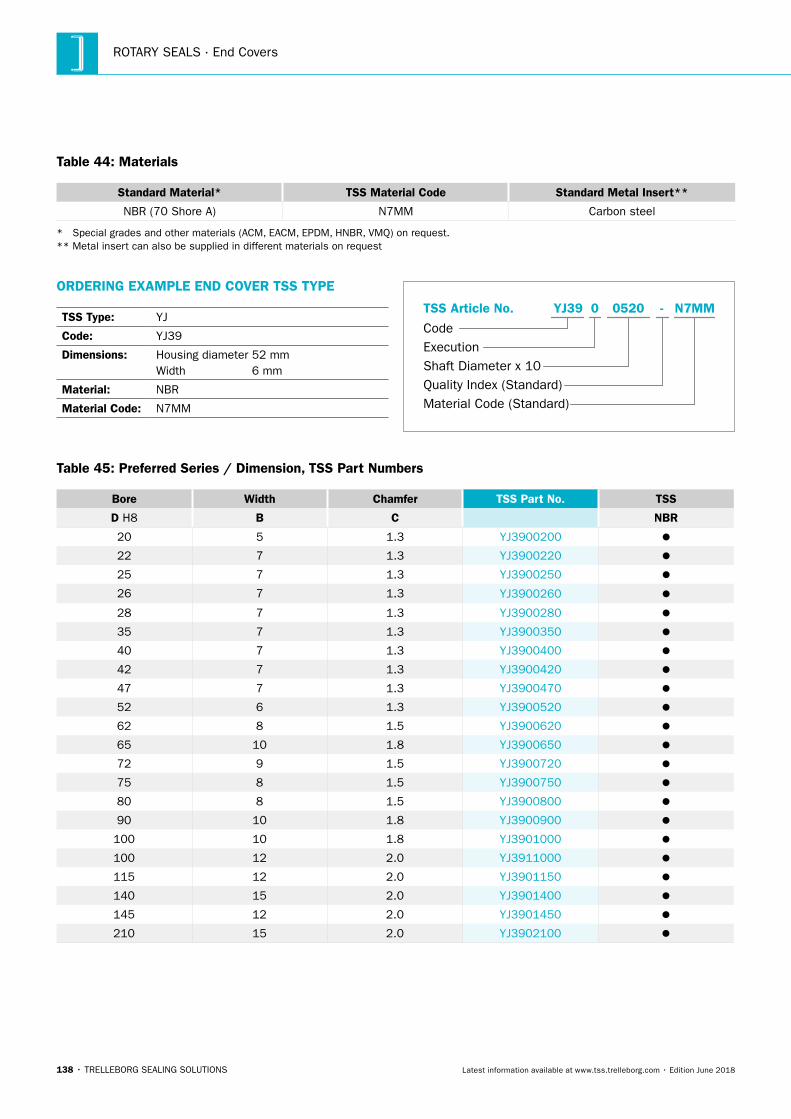
ROTARY SEALS · End Covers
138 • TRELLEBORG SEALING SOLUTIONS Latest information available at www.tss.trelleborg.com • Edition June 2018
Table 44: Materials
Standard Material* TSS Material Code Standard Metal Insert**
NBR (70 Shore A) N7MM Carbon steel
* Special grades and other materials (ACM, EACM, EPDM, HNBR, VMQ) on request. ** Metal insert can also be supplied in different materials on request
ORDERING EXAMPLE END COVER TSS TYPE
TSS Type: YJ
Code: YJ39
Dimensions: Housing diameter 52 mmWidth 6 mm
Material: NBR
Material Code: N7MM Material Code (Standard)
Code
TSS Article No. -
Shaft Diameter x 10Quality Index (Standard)
YJ39
Execution
05200 N7MM
Table 45: Preferred Series / Dimension, TSS Part Numbers
Bore Width Chamfer TSS Part No. TSS
D H8 B C NBR
20 5 1.3 YJ3900200
22 7 1.3 YJ3900220
25 7 1.3 YJ3900250
26 7 1.3 YJ3900260
28 7 1.3 YJ3900280
35 7 1.3 YJ3900350
40 7 1.3 YJ3900400
42 7 1.3 YJ3900420
47 7 1.3 YJ3900470
52 6 1.3 YJ3900520
62 8 1.5 YJ3900620
65 10 1.8 YJ3900650
72 9 1.5 YJ3900720
75 8 1.5 YJ3900750
80 8 1.5 YJ3900800
90 10 1.8 YJ3900900
100 10 1.8 YJ3901000
100 12 2.0 YJ3911000
115 12 2.0 YJ3901150
140 15 2.0 YJ3901400
145 12 2.0 YJ3901450
210 15 2.0 YJ3902100
TRELLEBORG SEALING SOLUTIONS • 139Latest information available at www.tss.trelleborg.com • Edition June 2018
Shaft Repair Kit

ROTARY SEALS · Shaft Repair Kit
140 • TRELLEBORG SEALING SOLUTIONS Latest information available at www.tss.trelleborg.com • Edition June 2018
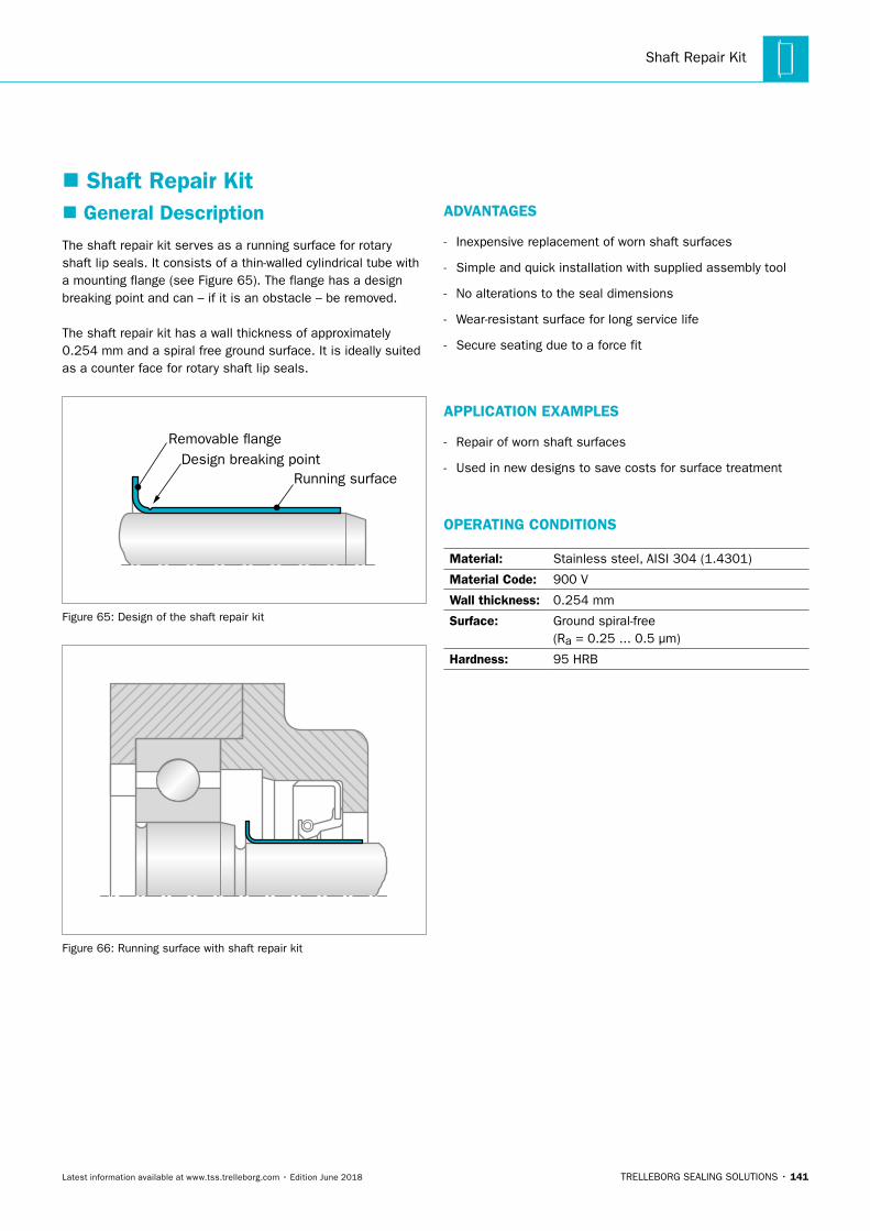
Shaft Repair Kit
TRELLEBORG SEALING SOLUTIONS • 141Latest information available at www.tss.trelleborg.com • Edition June 2018
� Shaft Repair Kit � General Description
The shaft repair kit serves as a running surface for rotary shaft lip seals. It consists of a thin-walled cylindrical tube with a mounting flange (see Figure 65). The flange has a design breaking point and can – if it is an obstacle – be removed.
The shaft repair kit has a wall thickness of approximately 0.254 mm and a spiral free ground surface. It is ideally suited as a counter face for rotary shaft lip seals.
Removable �ange
Running surfaceDesign breaking point
Figure 65: Design of the shaft repair kit
Figure 66: Running surface with shaft repair kit
ADVANTAGES
- Inexpensive replacement of worn shaft surfaces
- Simple and quick installation with supplied assembly tool
- No alterations to the seal dimensions
- Wear-resistant surface for long service life
- Secure seating due to a force fit
APPLICATION EXAMPLES
- Repair of worn shaft surfaces
- Used in new designs to save costs for surface treatment
OPERATING CONDITIONS
Material: Stainless steel, AISI 304 (1.4301)
Material Code: 900 V
Wall thickness: 0.254 mm
Surface: Ground spiral-free (Ra = 0.25 ... 0.5 μm)
Hardness: 95 HRB
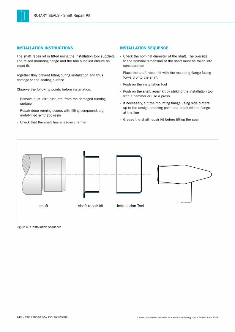
ROTARY SEALS · Shaft Repair Kit
142 • TRELLEBORG SEALING SOLUTIONS Latest information available at www.tss.trelleborg.com • Edition June 2018
INSTALLATION INSTRUCTIONS
The shaft repair kit is fitted using the installation tool supplied. The raised mounting flange and the tool supplied ensure an exact fit.
Together they prevent tilting during installation and thus damage to the sealing surface.
Observe the following points before installation:
- Remove dust, dirt, rust, etc. from the damaged running surface
- Repair deep running scores with filling compound, e.g. metal-filled synthetic resin
- Check that the shaft has a lead-in chamfer
INSTALLATION SEQUENCE
- Check the nominal diameter of the shaft. The oversize to the nominal dimension of the shaft must be taken into consideration
- Place the shaft repair kit with the mounting flange facing forward onto the shaft
- Push on the installation tool
- Push on the shaft repair kit by striking the installation tool with a hammer or use a press
- If necessary, cut the mounting flange using side cutters up to the design breaking point and break off the flange at the line
- Grease the shaft repair kit before fitting the seal
shaft installation Toolshaft repair kit
Figure 67: Installation sequence
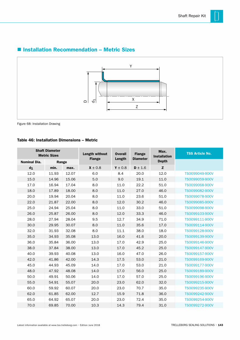
Shaft Repair Kit
TRELLEBORG SEALING SOLUTIONS • 143Latest information available at www.tss.trelleborg.com • Edition June 2018
� Installation Recommendation – Metric Sizes
D d 1
Z
Y
X
Figure 68: Installation Drawing
Table 46: Installation Dimensions – Metric
Shaft Diameter Metric Sizes Length without
FlangeOverallLength
FlangeDiameter
Max.Installation
Depth
TSS Article No.
Nominal Dia. Range
d1 min. max. X ± 0.8 Y ± 0.8 D ± 1.6 Z
12.0 11.93 12.07 6.0 8.4 20.0 12.0 TS0099049-900V
15.0 14.96 15.06 5.0 9.0 19.1 11.0 TS0099059-900V
17.0 16.94 17.04 8.0 11.0 22.2 51.0 TS0099068-900V
18.0 17.89 18.00 8.0 11.0 27.0 46.0 TS0099082-900V
20.0 19.94 20.04 8.0 11.0 23.6 51.0 TS0099078-900V
22.0 21.87 22.00 8.0 12.0 30.2 46.0 TS0099085-900V
25.0 24.94 25.04 8.0 11.0 33.0 51.0 TS0099098-900V
26.0 25.87 26.00 8.0 12.0 33.3 46.0 TS0099103-900V
28.0 27.94 28.04 9.5 12.7 34.9 71.0 TS0099111-900V
30.0 29.95 30.07 8.0 11.0 35.6 17.0 TS0099114-900V
32.0 31.93 32.08 8.0 11.1 38.0 18.0 TS0099128-900V
35.0 34.93 35.08 13.0 16.0 41.6 20.0 TS0099139-900V
36.0 35.84 36.00 13.0 17.0 42.9 25.0 TS0099146-900V
38.0 37.84 38.00 13.0 17.0 45.2 25.0 TS0099147-900V
40.0 39.93 40.08 13.0 16.0 47.0 26.0 TS0099157-900V
42.0 41.86 42.00 14.3 17.5 53.0 21.0 TS0099169-900V
45.0 44.93 45.09 14.0 17.0 53.0 21.0 TS0099177-900V
48.0 47.92 48.08 14.0 17.0 56.0 25.0 TS0099189-900V
50.0 49.91 50.06 14.0 17.0 57.0 25.0 TS0099196-900V
55.0 54.91 55.07 20.0 23.0 62.0 32.0 TS0099215-900V
60.0 59.92 60.07 20.0 23.0 70.7 35.0 TS0099235-900V
62.0 61.85 62.00 12.7 15.9 71.8 36.0 TS0099242-900V
65.0 64.92 65.07 20.0 23.0 72.4 35.0 TS0099254-900V
70.0 69.85 70.00 10.3 14.3 79.4 31.0 TS0099272-900V
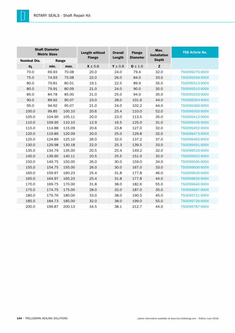
ROTARY SEALS · Shaft Repair Kit
144 • TRELLEBORG SEALING SOLUTIONS Latest information available at www.tss.trelleborg.com • Edition June 2018
Shaft Diameter Metric Sizes Length without
FlangeOverallLength
FlangeDiameter
Max.Installation
Depth
TSS Article No.
Nominal Dia. Range
d1 min. max. X ± 0.8 Y ± 0.8 D ± 1.6 Z
70.0 69.93 70.08 20.0 24.0 79.4 32.0 TS0099276-900V
75.0 74.93 75.08 22.0 26.0 84.0 33.0 TS0099294-900V
80.0 79.81 80.01 19.1 22.5 89.9 35.0 TS0099313-900V
80.0 79.91 80.09 21.0 24.0 90.0 35.0 TS0099315-900V
85.0 84.78 85.00 21.0 25.0 94.0 35.0 TS0099333-900V
90.0 89.92 90.07 23.0 28.0 101.6 44.0 TS0099354-900V
95.0 94.92 95.07 21.0 24.0 102.2 44.0 TS0099369-900V
100.0 99.85 100.10 20.6 25.4 110.0 52.0 TS0099393-900V
105.0 104.90 105.11 20.0 23.0 113.5 35.0 TS0099413-900V
110.0 109.90 110.10 12.9 16.5 125.0 31.0 TS0099435-900V
115.0 114.88 115.09 20.6 23.8 127.0 32.0 TS0099452-900V
120.0 119.89 120.09 20.0 25.0 129.8 32.0 TS0099473-900V
125.0 124.89 125.10 26.0 32.0 137.2 37.0 TS0099492-900V
130.0 129.98 130.18 22.0 25.3 139.5 33.0 TS0099491-900V
135.0 134.79 135.00 20.5 25.4 149.2 32.0 TS0099533-900V
140.0 139.90 140.11 20.5 25.5 151.0 32.0 TS0099552-900V
150.0 149.75 150.00 26.0 30.0 159.0 34.0 TS0099595-900V
155.0 154.75 155.00 26.0 30.0 167.0 33.0 TS0099606-900V
160.0 159.97 160.23 25.4 31.8 177.8 46.0 TS0099630-900V
165.0 164.97 165.23 25.4 31.8 177.8 44.0 TS0099650-900V
170.0 169.75 170.00 31.8 38.0 182.6 55.0 TS0099640-900V
175.0 174.75 175.00 28.0 32.0 187.0 35.0 TS0099687-900V
180.0 179.76 180.00 33.0 38.0 190.5 45.0 TS0099721-900V
185.0 184.73 185.00 32.0 38.0 199.0 55.0 TS0099726-900V
200.0 199.87 200.13 34.5 38.1 212.7 44.0 TS0099787-900V
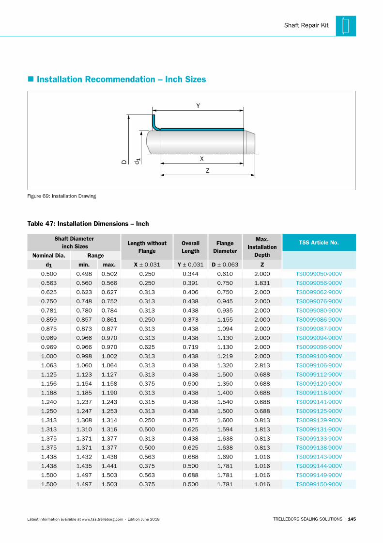
Shaft Repair Kit
TRELLEBORG SEALING SOLUTIONS • 145Latest information available at www.tss.trelleborg.com • Edition June 2018
� Installation Recommendation – Inch Sizes
Z
Y
XD d 1
Figure 69: Installation Drawing
Table 47: Installation Dimensions – Inch
Shaft Diameter inch Sizes Length without
FlangeOverallLength
FlangeDiameter
Max.Installation
Depth
TSS Article No.
Nominal Dia. Range
d1 min. max. X ± 0.031 Y ± 0.031 D ± 0.063 Z
0.500 0.498 0.502 0.250 0.344 0.610 2.000 TS0099050-900V
0.563 0.560 0.566 0.250 0.391 0.750 1.831 TS0099056-900V
0.625 0.623 0.627 0.313 0.406 0.750 2.000 TS0099062-900V
0.750 0.748 0.752 0.313 0.438 0.945 2.000 TS0099076-900V
0.781 0.780 0.784 0.313 0.438 0.935 2.000 TS0099080-900V
0.859 0.857 0.861 0.250 0.373 1.155 2.000 TS0099086-900V
0.875 0.873 0.877 0.313 0.438 1.094 2.000 TS0099087-900V
0.969 0.966 0.970 0.313 0.438 1.130 2.000 TS0099094-900V
0.969 0.966 0.970 0.625 0.719 1.130 2.000 TS0099096-900V
1.000 0.998 1.002 0.313 0.438 1.219 2.000 TS0099100-900V
1.063 1.060 1.064 0.313 0.438 1.320 2.813 TS0099106-900V
1.125 1.123 1.127 0.313 0.438 1.500 0.688 TS0099112-900V
1.156 1.154 1.158 0.375 0.500 1.350 0.688 TS0099120-900V
1.188 1.185 1.190 0.313 0.438 1.400 0.688 TS0099118-900V
1.240 1.237 1.243 0.315 0.438 1.540 0.688 TS0099141-900V
1.250 1.247 1.253 0.313 0.438 1.500 0.688 TS0099125-900V
1.313 1.308 1.314 0.250 0.375 1.600 0.813 TS0099129-900V
1.313 1.310 1.316 0.500 0.625 1.594 1.813 TS0099131-900V
1.375 1.371 1.377 0.313 0.438 1.638 0.813 TS0099133-900V
1.375 1.371 1.377 0.500 0.625 1.638 0.813 TS0099138-900V
1.438 1.432 1.438 0.563 0.688 1.690 1.016 TS0099143-900V
1.438 1.435 1.441 0.375 0.500 1.781 1.016 TS0099144-900V
1.500 1.497 1.503 0.563 0.688 1.781 1.016 TS0099149-900V
1.500 1.497 1.503 0.375 0.500 1.781 1.016 TS0099150-900V
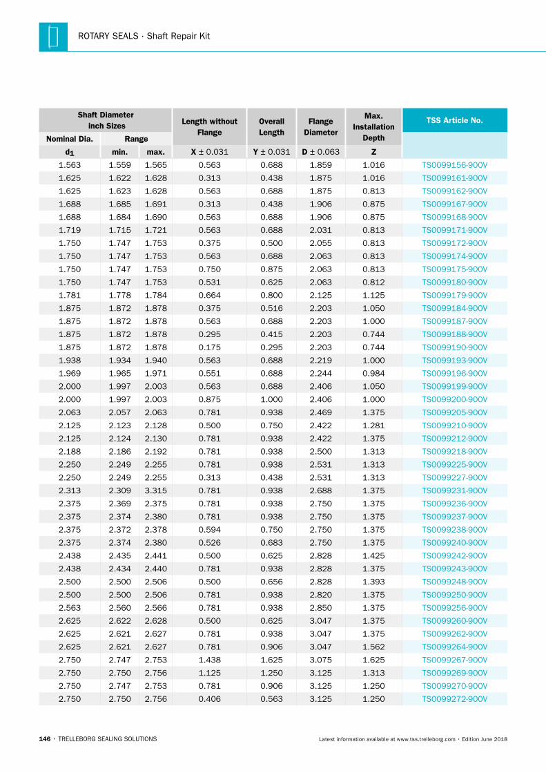
ROTARY SEALS · Shaft Repair Kit
146 • TRELLEBORG SEALING SOLUTIONS Latest information available at www.tss.trelleborg.com • Edition June 2018
Shaft Diameter inch Sizes Length without
FlangeOverallLength
FlangeDiameter
Max.Installation
Depth
TSS Article No.
Nominal Dia. Range
d1 min. max. X ± 0.031 Y ± 0.031 D ± 0.063 Z
1.563 1.559 1.565 0.563 0.688 1.859 1.016 TS0099156-900V
1.625 1.622 1.628 0.313 0.438 1.875 1.016 TS0099161-900V
1.625 1.623 1.628 0.563 0.688 1.875 0.813 TS0099162-900V
1.688 1.685 1.691 0.313 0.438 1.906 0.875 TS0099167-900V
1.688 1.684 1.690 0.563 0.688 1.906 0.875 TS0099168-900V
1.719 1.715 1.721 0.563 0.688 2.031 0.813 TS0099171-900V
1.750 1.747 1.753 0.375 0.500 2.055 0.813 TS0099172-900V
1.750 1.747 1.753 0.563 0.688 2.063 0.813 TS0099174-900V
1.750 1.747 1.753 0.750 0.875 2.063 0.813 TS0099175-900V
1.750 1.747 1.753 0.531 0.625 2.063 0.812 TS0099180-900V
1.781 1.778 1.784 0.664 0.800 2.125 1.125 TS0099179-900V
1.875 1.872 1.878 0.375 0.516 2.203 1.050 TS0099184-900V
1.875 1.872 1.878 0.563 0.688 2.203 1.000 TS0099187-900V
1.875 1.872 1.878 0.295 0.415 2.203 0.744 TS0099188-900V
1.875 1.872 1.878 0.175 0.295 2.203 0.744 TS0099190-900V
1.938 1.934 1.940 0.563 0.688 2.219 1.000 TS0099193-900V
1.969 1.965 1.971 0.551 0.688 2.244 0.984 TS0099196-900V
2.000 1.997 2.003 0.563 0.688 2.406 1.050 TS0099199-900V
2.000 1.997 2.003 0.875 1.000 2.406 1.000 TS0099200-900V
2.063 2.057 2.063 0.781 0.938 2.469 1.375 TS0099205-900V
2.125 2.123 2.128 0.500 0.750 2.422 1.281 TS0099210-900V
2.125 2.124 2.130 0.781 0.938 2.422 1.375 TS0099212-900V
2.188 2.186 2.192 0.781 0.938 2.500 1.313 TS0099218-900V
2.250 2.249 2.255 0.781 0.938 2.531 1.313 TS0099225-900V
2.250 2.249 2.255 0.313 0.438 2.531 1.313 TS0099227-900V
2.313 2.309 3.315 0.781 0.938 2.688 1.375 TS0099231-900V
2.375 2.369 2.375 0.781 0.938 2.750 1.375 TS0099236-900V
2.375 2.374 2.380 0.781 0.938 2.750 1.375 TS0099237-900V
2.375 2.372 2.378 0.594 0.750 2.750 1.375 TS0099238-900V
2.375 2.374 2.380 0.526 0.683 2.750 1.375 TS0099240-900V
2.438 2.435 2.441 0.500 0.625 2.828 1.425 TS0099242-900V
2.438 2.434 2.440 0.781 0.938 2.828 1.375 TS0099243-900V
2.500 2.500 2.506 0.500 0.656 2.828 1.393 TS0099248-900V
2.500 2.500 2.506 0.781 0.938 2.820 1.375 TS0099250-900V
2.563 2.560 2.566 0.781 0.938 2.850 1.375 TS0099256-900V
2.625 2.622 2.628 0.500 0.625 3.047 1.375 TS0099260-900V
2.625 2.621 2.627 0.781 0.938 3.047 1.375 TS0099262-900V
2.625 2.621 2.627 0.781 0.906 3.047 1.562 TS0099264-900V
2.750 2.747 2.753 1.438 1.625 3.075 1.625 TS0099267-900V
2.750 2.750 2.756 1.125 1.250 3.125 1.313 TS0099269-900V
2.750 2.747 2.753 0.781 0.906 3.125 1.250 TS0099270-900V
2.750 2.750 2.756 0.406 0.563 3.125 1.250 TS0099272-900V
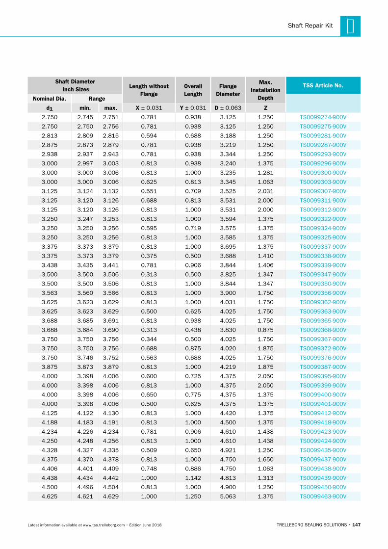
Shaft Repair Kit
TRELLEBORG SEALING SOLUTIONS • 147Latest information available at www.tss.trelleborg.com • Edition June 2018
Shaft Diameter inch Sizes Length without
FlangeOverallLength
FlangeDiameter
Max.Installation
Depth
TSS Article No.
Nominal Dia. Range
d1 min. max. X ± 0.031 Y ± 0.031 D ± 0.063 Z
2.750 2.745 2.751 0.781 0.938 3.125 1.250 TS0099274-900V
2.750 2.750 2.756 0.781 0.938 3.125 1.250 TS0099275-900V
2.813 2.809 2.815 0.594 0.688 3.188 1.250 TS0099281-900V
2.875 2.873 2.879 0.781 0.938 3.219 1.250 TS0099287-900V
2.938 2.937 2.943 0.781 0.938 3.344 1.250 TS0099293-900V
3.000 2.997 3.003 0.813 0.938 3.240 1.375 TS0099296-900V
3.000 3.000 3.006 0.813 1.000 3.235 1.281 TS0099300-900V
3.000 3.000 3.006 0.625 0.813 3.345 1.063 TS0099303-900V
3.125 3.124 3.132 0.551 0.709 3.525 2.031 TS0099307-900V
3.125 3.120 3.126 0.688 0.813 3.531 2.000 TS0099311-900V
3.125 3.120 3.126 0.813 1.000 3.531 2.000 TS0099312-900V
3.250 3.247 3.253 0.813 1.000 3.594 1.375 TS0099322-900V
3.250 3.250 3.256 0.595 0.719 3.575 1.375 TS0099324-900V
3.250 3.250 3.256 0.813 1.000 3.585 1.375 TS0099325-900V
3.375 3.373 3.379 0.813 1.000 3.695 1.375 TS0099337-900V
3.375 3.373 3.379 0.375 0.500 3.688 1.410 TS0099338-900V
3.438 3.435 3.441 0.781 0.906 3.844 1.406 TS0099339-900V
3.500 3.500 3.506 0.313 0.500 3.825 1.347 TS0099347-900V
3.500 3.500 3.506 0.813 1.000 3.844 1.347 TS0099350-900V
3.563 3.560 3.566 0.813 1.000 3.900 1.750 TS0099356-900V
3.625 3.623 3.629 0.813 1.000 4.031 1.750 TS0099362-900V
3.625 3.623 3.629 0.500 0.625 4.025 1.750 TS0099363-900V
3.688 3.685 3.691 0.813 0.938 4.025 1.750 TS0099365-900V
3.688 3.684 3.690 0.313 0.438 3.830 0.875 TS0099368-900V
3.750 3.750 3.756 0.344 0.500 4.025 1.750 TS0099367-900V
3.750 3.750 3.756 0.688 0.875 4.020 1.875 TS0099372-900V
3.750 3.746 3.752 0.563 0.688 4.025 1.750 TS0099376-900V
3.875 3.873 3.879 0.813 1.000 4.219 1.875 TS0099387-900V
4.000 3.398 4.006 0.600 0.725 4.375 2.050 TS0099395-900V
4.000 3.398 4.006 0.813 1.000 4.375 2.050 TS0099399-900V
4.000 3.398 4.006 0.650 0.775 4.375 1.375 TS0099400-900V
4.000 3.398 4.006 0.500 0.625 4.375 1.375 TS0099401-900V
4.125 4.122 4.130 0.813 1.000 4.420 1.375 TS0099412-900V
4.188 4.183 4.191 0.813 1.000 4.500 1.375 TS0099418-900V
4.234 4.226 4.234 0.781 0.906 4.610 1.438 TS0099423-900V
4.250 4.248 4.256 0.813 1.000 4.610 1.438 TS0099424-900V
4.328 4.327 4.335 0.509 0.650 4.921 1.250 TS0099435-900V
4.375 4.370 4.378 0.813 1.000 4.750 1.650 TS0099437-900V
4.406 4.401 4.409 0.748 0.886 4.750 1.063 TS0099438-900V
4.438 4.434 4.442 1.000 1.142 4.813 1.313 TS0099439-900V
4.500 4.496 4.504 0.813 1.000 4.900 1.250 TS0099450-900V
4.625 4.621 4.629 1.000 1.250 5.063 1.375 TS0099463-900V
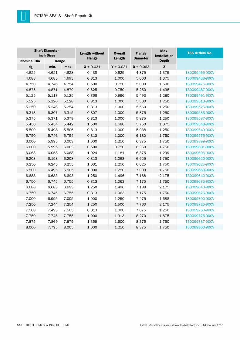
ROTARY SEALS · Shaft Repair Kit
148 • TRELLEBORG SEALING SOLUTIONS Latest information available at www.tss.trelleborg.com • Edition June 2018
Shaft Diameter inch Sizes Length without
FlangeOverallLength
FlangeDiameter
Max.Installation
Depth
TSS Article No.
Nominal Dia. Range
d1 min. max. X ± 0.031 Y ± 0.031 D ± 0.063 Z
4.625 4.621 4.628 0.438 0.625 4.875 1.375 TS0099465-900V
4.688 4.685 4.693 0.813 1.000 5.063 1.375 TS0099468-900V
4.750 4.746 4.754 0.500 0.750 5.000 1.500 TS0099475-900V
4.875 4.871 4.879 0.625 0.750 5.250 1.438 TS0099487-900V
5.125 5.117 5.125 0.866 0.996 5.493 1.280 TS0099491-900V
5.125 5.120 5.128 0.813 1.000 5.500 1.250 TS0099513-900V
5.250 5.246 5.254 0.813 1.000 5.560 1.250 TS0099525-900V
5.313 5.307 5.315 0.807 1.000 5.875 1.250 TS0099533-900V
5.375 5.371 5.379 0.813 1.000 5.875 1.250 TS0099537-900V
5.438 5.434 5.442 1.500 1.688 5.750 1.875 TS0099548-900V
5.500 5.498 5.506 0.813 1.000 5.938 1.250 TS0099549-900V
5.750 5.746 5.754 0.813 1.000 6.180 1.750 TS0099575-900V
6.000 5.995 6.003 1.000 1.250 6.375 1.750 TS0099599-900V
6.000 5.995 6.003 0.500 0.750 6.360 1.750 TS0099601-900V
6.063 6.058 6.068 1.024 1.181 6.375 1.299 TS0099605-900V
6.203 6.198 6.208 0.813 1.063 6.625 1.750 TS0099620-900V
6.250 6.245 6.255 1.031 1.250 6.625 1.750 TS0099625-900V
6.500 6.495 6.505 1.000 1.250 7.000 1.750 TS0099650-900V
6.688 6.683 6.693 1.250 1.496 7.188 2.175 TS0099640-900V
6.750 6.745 6.755 0.813 1.063 7.175 1.750 TS0099675-900V
6.688 6.683 6.693 1.250 1.496 7.188 2.175 TS0099640-900V
6.750 6.745 6.755 0.813 1.063 7.175 1.750 TS0099675-900V
7.000 6.995 7.005 1.000 1.250 7.475 1.688 TS0099700-900V
7.250 7.244 7.254 1.250 1.500 7.760 2.175 TS0099725-900V
7.500 7.495 7.505 0.813 1.000 7.875 1.250 TS0099750-900V
7.750 7.745 7.755 1.000 1.313 8.270 1.875 TS0099775-900V
7.875 7.869 7.879 1.359 1.500 8.375 1.750 TS0099787-900V
8.000 7.795 8.005 1.000 1.250 8.375 1.750 TS0099800-900V
TRELLEBORG SEALING SOLUTIONS • 149Latest information available at www.tss.trelleborg.com • Edition June 2018
Forsheda®V-Ring

ROTARY SEALS · Forsheda® V-Ring
150 • TRELLEBORG SEALING SOLUTIONS Latest information available at www.tss.trelleborg.com • Edition June 2018
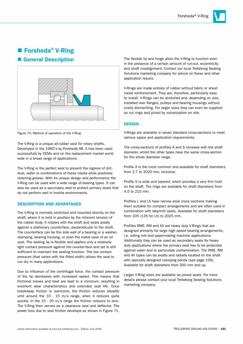
Forsheda® V-Ring
TRELLEBORG SEALING SOLUTIONS • 151Latest information available at www.tss.trelleborg.com • Edition June 2018
� Forsheda®V-Ring � General Description
Figure 70: Method of operation of the V-Ring
The V-Ring is a unique all-rubber seal for rotary shafts. Developed in the 1960's by Forsheda AB, it has been used successfully by OEMs and on the replacement market world wide in a broad range of applications.
The V-Ring is the perfect seal to prevent the ingress of dirt, dust, water or combinations of these media while positively retaining grease. With its unique design and performance the V-Ring can be used with a wide range of bearing types. It can also be used as a secondary seal to protect primary seals that do not perform well in hostile environments.
DESCRIPTION AND ADVANTAGES
The V-Ring is normally stretched and mounted directly on the shaft, where it is held in position by the inherent tension of the rubber body. It rotates with the shaft and seals axially against a stationary counterface, perpendicular to the shaft. The counterface can be the side wall of a bearing or a washer, stamping, bearing housing, or even the metal case of an oil seal. The sealing lip is flexible and applies only a relatively light contact pressure against the counter-face and yet is still sufficient to maintain the sealing function. The low contact pressure (that varies with the fitted width) allows the seal to run dry in many applications.
Due to influence of the centrifugal force, the contact pressure of the lip decreases with increased speed. This means that frictional losses and heat are kept to a minimum, resulting in excellent wear characteristics and extended seal life. Once breakaway friction is overcome, the friction reduces steadily until around the 10 - 15 m/s range, when it reduces quite quickly. In the 15 - 20 m/s range the friction reduces to zero. The V-Ring then serves as a clearance seal and deflector. The power loss due to seal friction develops as shown in Figure 71.
The flexible lip and hinge allow the V-Ring to function even in the presence of a certain amount of run-out, eccentricity and shaft misalignment. Contact our local Trelleborg Sealing Solutions marketing company for advice on these and other application issues.
V-Rings are made entirely of rubber without fabric or sheet metal reinforcement. They are, therefore, particularly easy to install. V-Rings can be stretched and, depending on size, installed over flanges, pulleys and bearing housings without costly dismantling. For larger sizes they can even be supplied as cut rings and joined by vulcanization on site.
DESIGN
V-Rings are available in seven standard cross-sections to meet various space and application requirements.
The cross-sections of profiles A and S increase with the shaft diameter, whilst the other types have the same cross-section for the whole diameter range.
Profile A is the most common and available for shaft diameters from 2.7 to 2020 mm, inclusive.
Profile S is wide and tapered, which provides a very firm hold on the shaft. The rings are available for shaft diameters from 4.5 to 210 mm.
Profiles L and LX have narrow axial cross sections making them suitable for compact arrangements and are often used in combination with labyrinth seals. Available for shaft diameters from 105 (135 for LX) to 2025 mm.
Profiles RME, RM and AX are heavy duty V-Rings that are designed primarily for large high speed bearing arrangements, i.e. rolling mill and papermaking machine applications. Additionally they can be used as secondary seals for heavy duty applications where the primary seal has to be protected against water and or particulate contamination. The RME, RM and AX types can be axially and radially located on the shaft with specially designed clamping bands (see page 156). Available for shaft diameters from 300 mm and up.
Larger V-Ring sizes are available as joined seals. For more details please contact your local Trelleborg Sealing Solutions marketing company.
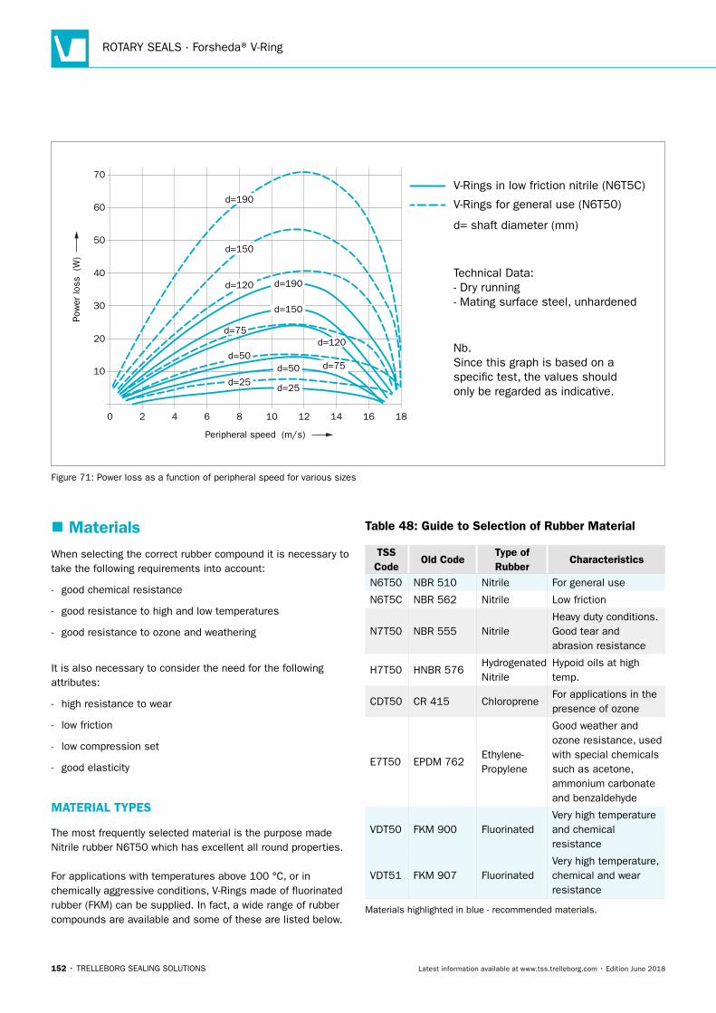
ROTARY SEALS · Forsheda® V-Ring
152 • TRELLEBORG SEALING SOLUTIONS Latest information available at www.tss.trelleborg.com • Edition June 2018
0
10
20
30
40
50
60
70
Peripheral speed (m/s)
Pow
er lo
ss
(W)
V-Rings in low friction nitrile (N6T5C)
V-Rings for general use (N6T50)
d= shaft diameter (mm)
Nb.Since this graph is based on a speci�c test, the values shouldonly be regarded as indicative.
Technical Data:- Dry running- Mating surface steel, unhardened
2 4 6 8 10 12 14 16 18
d=25
d=50
d=120
d=150
d=190
d=120
d=25
d=190
d=150
d=50d=75
d=75
Figure 71: Power loss as a function of peripheral speed for various sizes
� MaterialsWhen selecting the correct rubber compound it is necessary to take the following requirements into account:
- good chemical resistance
- good resistance to high and low temperatures
- good resistance to ozone and weathering
It is also necessary to consider the need for the following attributes:
- high resistance to wear
- low friction
- low compression set
- good elasticity
MATERIAL TYPES
The most frequently selected material is the purpose made Nitrile rubber N6T50 which has excellent all round properties.
For applications with temperatures above 100 °C, or in chemically aggressive conditions, V-Rings made of fluorinated rubber (FKM) can be supplied. In fact, a wide range of rubber compounds are available and some of these are listed below.
Table 48: Guide to Selection of Rubber Material
TSS Code
Old CodeType of Rubber
Characteristics
N6T50 NBR 510 Nitrile For general use
N6T5C NBR 562 Nitrile Low friction
N7T50 NBR 555 NitrileHeavy duty conditions.Good tear andabrasion resistance
H7T50 HNBR 576HydrogenatedNitrile
Hypoid oils at hightemp.
CDT50 CR 415 ChloropreneFor applications in thepresence of ozone
E7T50 EPDM 762Ethylene-Propylene
Good weather andozone resistance, usedwith special chemicalssuch as acetone,ammonium carbonateand benzaldehyde
VDT50 FKM 900 FluorinatedVery high temperatureand chemical resistance
VDT51 FKM 907 FluorinatedVery high temperature,chemical and wear resistance
Materials highlighted in blue - recommended materials.
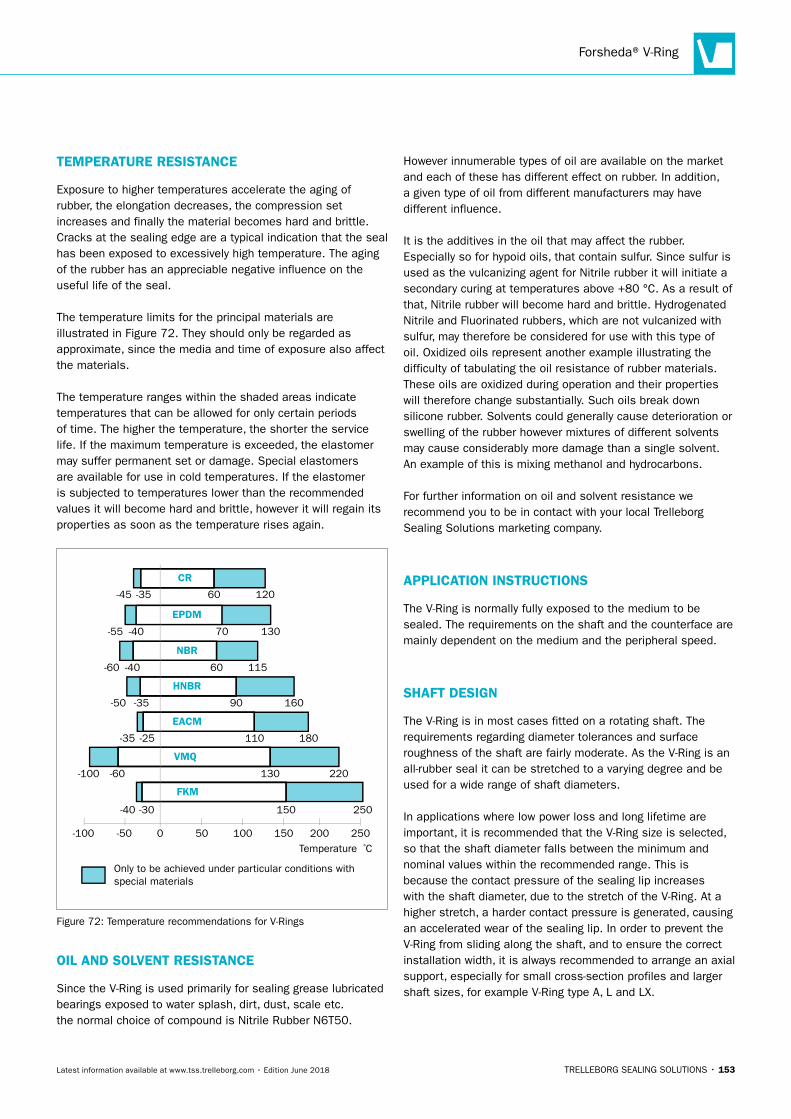
Forsheda® V-Ring
TRELLEBORG SEALING SOLUTIONS • 153Latest information available at www.tss.trelleborg.com • Edition June 2018
TEMPERATURE RESISTANCE
Exposure to higher temperatures accelerate the aging of rubber, the elongation decreases, the compression set increases and finally the material becomes hard and brittle. Cracks at the sealing edge are a typical indication that the seal has been exposed to excessively high temperature. The aging of the rubber has an appreciable negative influence on the useful life of the seal.
The temperature limits for the principal materials are illustrated in Figure 72. They should only be regarded as approximate, since the media and time of exposure also affect the materials.
The temperature ranges within the shaded areas indicate temperatures that can be allowed for only certain periods of time. The higher the temperature, the shorter the service life. If the maximum temperature is exceeded, the elastomer may suffer permanent set or damage. Special elastomers are available for use in cold temperatures. If the elastomer is subjected to temperatures lower than the recommended values it will become hard and brittle, however it will regain its properties as soon as the temperature rises again.
Temperature ºC
Only to be achieved under particular conditions with special materials
0-50-100
-40 -30 150 250
220130
180110
16090
11560
13070
12060
-60-100
-35 -25
-50 -35
-60 -40
-55 -40
-45 -35
50 100 150 200 250
CR
EPDM
NBR
HNBR
EACM
VMQ
FKM
Figure 72: Temperature recommendations for V-Rings
OIL AND SOLVENT RESISTANCE
Since the V-Ring is used primarily for sealing grease lubricated bearings exposed to water splash, dirt, dust, scale etc. the normal choice of compound is Nitrile Rubber N6T50.
However innumerable types of oil are available on the market and each of these has different effect on rubber. In addition, a given type of oil from different manufacturers may have different influence.
It is the additives in the oil that may affect the rubber. Especially so for hypoid oils, that contain sulfur. Since sulfur is used as the vulcanizing agent for Nitrile rubber it will initiate a secondary curing at temperatures above +80 °C. As a result of that, Nitrile rubber will become hard and brittle. Hydrogenated Nitrile and Fluorinated rubbers, which are not vulcanized with sulfur, may therefore be considered for use with this type of oil. Oxidized oils represent another example illustrating the difficulty of tabulating the oil resistance of rubber materials. These oils are oxidized during operation and their properties will therefore change substantially. Such oils break down silicone rubber. Solvents could generally cause deterioration or swelling of the rubber however mixtures of different solvents may cause considerably more damage than a single solvent. An example of this is mixing methanol and hydrocarbons.
For further information on oil and solvent resistance we recommend you to be in contact with your local Trelleborg Sealing Solutions marketing company.
APPLICATION INSTRUCTIONS
The V-Ring is normally fully exposed to the medium to be sealed. The requirements on the shaft and the counterface are mainly dependent on the medium and the peripheral speed.
SHAFT DESIGN
The V-Ring is in most cases fitted on a rotating shaft. The requirements regarding diameter tolerances and surface roughness of the shaft are fairly moderate. As the V-Ring is an all-rubber seal it can be stretched to a varying degree and be used for a wide range of shaft diameters.
In applications where low power loss and long lifetime are important, it is recommended that the V-Ring size is selected, so that the shaft diameter falls between the minimum and nominal values within the recommended range. This is because the contact pressure of the sealing lip increases with the shaft diameter, due to the stretch of the V-Ring. At a higher stretch, a harder contact pressure is generated, causing an accelerated wear of the sealing lip. In order to prevent the V-Ring from sliding along the shaft, and to ensure the correct installation width, it is always recommended to arrange an axial support, especially for small cross-section profiles and larger shaft sizes, for example V-Ring type A, L and LX.
ROTARY SEALS · Forsheda® V-Ring
154 • TRELLEBORG SEALING SOLUTIONS Latest information available at www.tss.trelleborg.com • Edition June 2018
The surface roughness of the shaft should in general not exceed Ra 6.3 μm. For sealing fluids and fine particles, a maximum of Ra 3.2 μm is recommended. Sharp edges and burrs, which can damage the V-Ring must be avoided.
COUNTER-FACE DESIGN
The condition of the counter-face has a great influence on the sealing function. The medium to be sealed and the peripheral speed of the shaft determine the requirements regarding surface roughness and material of the counter-face. It is important that it is smooth and flat without any sharp edges. To achieve the full effect of the flinger action, the V-Ring should always be designed in a relatively open space. Equally important is to keep the gap between the shaft and the counter-face as small as possible, in order to prevent entry of the V-Ring lip during the installation. Recommended application dimensions are given in the dimension tables.
MATERIAL AND MATERIAL HARDNESS
Cold rolled steel sheet, stainless steel or zinc plated sheet are excellent materials for the counter-face. However, the choice of material is highly dependent on the medium to be sealed.
For normal running conditions, conventional mild steel with a hardness of min. 125 HB is sufficient. For sealing against grease, oil and dry particles no further surface treatment is required. With an increase in speed and the presence of abrasive particles the hardness of the counter-face must also be increased.
The following materials are normally used :
Material Hardness HB Medium
Mild Steel 125 - 150 Water splash, sand,
dust
Grey Cast Iron 190 - 270 Water splash, sand,
dust
Sinter Bronze 100 - 160 Water, dust
Stainless Steel (Cr/Ni 18-8, C 0.1%)
150 - 200 Water
Stainless Steel (Cr/Ni 18-8, C 0.15%)
350Water and abrasive
particles
Work-hardened Acid Proof Steel
180 - 200 Chemicals
Tungsten Carbide 350 - 500 Water and scale
Forged Steel 200 - 255 Water and scale
Die-cast Aluminum 90 - 160 Water splash
SURFACE TREATMENT
When the counter-face is exposed to water or other corrosive media, it must be protected accordingly.Mild steel surfaces should either be zinc-plated and chromated, chromium plated, treated with an anticorrosion spray, or painted. The choice of treatment will depend on the overall running conditions.
Where the seal is immersed in water, stainless steel is recommended. However, due to the poor thermal conductivity of stainless steel it should not be used in dry running conditions unless the speed is slow (< 1 m/s).
SURFACE FINISH
The rate of abrasion of the V-Ring is influenced by a number of factors, one of which is the surface finish of the counter-face. The choice of surface finish will depend on the media to be sealed and the shaft speed as well. It is not only the surface finish value as such that is important, but also the surface character. For turned surfaces, it is recommended to buff the surface with fine emery cloth to remove any sharp peaks arising from the turning operation.
Surfaces with a finish that is too fine, e.g. certain cold rolled steel surfaces, may cause a suction effect between the V-Ring lip and the counter-face resulting in noise problems and uneven running (so-called stick-slip effect).
The counterface surface must be free from scratch marks and other surface damages within the sealing area. This is important when sealing fluids and fine particles are present.
GUIDE TO RECOMMENDED SURFACE FINISH
Surface Finish μm Ra
Speed m/s
Medium
0.4 - 0.8 > 10 Oil, water, scale, fiber
0.8 - 1.6 5 - 10Oil splash, grease,
water splash
1.6 - 2.0 1 - 5 Grease, dust, water splash, scale
2.0 - 2.5 < 1 Grease, dust
The surface finish should not be lower than Ra 0.05 μm.
FLATNESS
The flatness of the counter-face is of importance, especially at higher shaft speeds.The maximum permissible flatness deviation is normally defined as 0.4 mm per 100 mm.
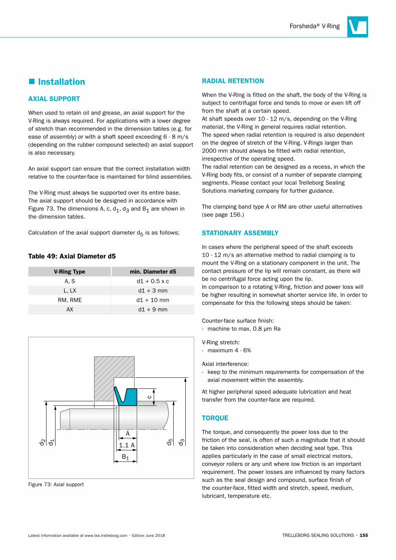
Forsheda® V-Ring
TRELLEBORG SEALING SOLUTIONS • 155Latest information available at www.tss.trelleborg.com • Edition June 2018
� Installation
AXIAL SUPPORT
When used to retain oil and grease, an axial support for the V-Ring is always required. For applications with a lower degree of stretch than recommended in the dimension tables (e.g. for ease of assembly) or with a shaft speed exceeding 6 - 8 m/s (depending on the rubber compound selected) an axial support is also necessary.
An axial support can ensure that the correct installation width relative to the counter-face is maintained for blind assemblies.
The V-Ring must always be supported over its entire base. The axial support should be designed in accordance with Figure 73. The dimensions A, c, d1, d3 and B1 are shown in the dimension tables.
Calculation of the axial support diameter d5 is as follows;
Table 49: Axial Diameter d5
V-Ring Type min. Diameter d5
A, S d1 + 0.5 x c
L, LX d1 + 3 mm
RM, RME d1 + 10 mm
AX d1 + 9 mm
A
1.1 A d 3d 2 d 5d 1
c
B1
Figure 73: Axial support
RADIAL RETENTION
When the V-Ring is fitted on the shaft, the body of the V-Ring is subject to centrifugal force and tends to move or even lift off from the shaft at a certain speed.At shaft speeds over 10 - 12 m/s, depending on the V-Ring material, the V-Ring in general requires radial retention.The speed when radial retention is required is also dependent on the degree of stretch of the V-Ring. V-Rings larger than 2000 mm should always be fitted with radial retention, irrespective of the operating speed.The radial retention can be designed as a recess, in which the V-Ring body fits, or consist of a number of separate clamping segments. Please contact your local Trelleborg Sealing Solutions marketing company for further guidance.
The clamping band type A or RM are other useful alternatives (see page 156.)
STATIONARY ASSEMBLY
In cases where the peripheral speed of the shaft exceeds 10 - 12 m/s an alternative method to radial clamping is to mount the V-Ring on a stationary component in the unit. The contact pressure of the lip will remain constant, as there will be no centrifugal force acting upon the lip.In comparison to a rotating V-Ring, friction and power loss will be higher resulting in somewhat shorter service life. In order to compensate for this the following steps should be taken:
Counter-face surface finish: - machine to max. 0.8 μm Ra
V-Ring stretch: - maximum 4 - 6%
Axial interference: - keep to the minimum requirements for compensation of the
axial movement within the assembly.
At higher peripheral speed adequate lubrication and heat transfer from the counter-face are required.
TORQUE
The torque, and consequently the power loss due to the friction of the seal, is often of such a magnitude that it should be taken into consideration when deciding seal type. This applies particularly in the case of small electrical motors, conveyor rollers or any unit where low friction is an important requirement. The power losses are influenced by many factors such as the seal design and compound, surface finish of the counter-face, fitted width and stretch, speed, medium, lubricant, temperature etc.
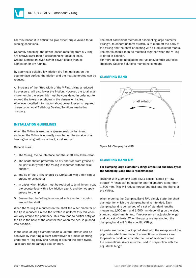
ROTARY SEALS · Forsheda® V-Ring
156 • TRELLEBORG SEALING SOLUTIONS Latest information available at www.tss.trelleborg.com • Edition June 2018
For this reason it is difficult to give exact torque values for all running conditions.
Generally speaking, the power losses resulting from a V-Ring are always lower than a corresponding radial oil seal.Grease lubrication gives higher power losses than oil lubrication or dry running.
By applying a suitable low friction dry film lubricant on the counter-face surface the friction and the heat generated can be reduced.
An increase of the fitted width of the V-Ring, giving a reduced lip pressure, will also lower the friction. However, the total axial movement in the assembly must be considered in order not to exceed the tolerances shown in the dimension tables.Whenever detailed information about power losses is required, consult your local Trelleborg Sealing Solutions marketing company.
INSTALLATION GUIDELINES
When the V-Ring is used as a grease seal/contaminant excluder, the V-Ring is normally mounted on the outside of a bearing housing, with or without, axial support.
General rules:
1. The V-Ring, the counter-face and the shaft should be clean
2. The shaft should preferably be dry and free from grease or oil, particularly when the V-Ring is mounted without axial support
3. The lip of the V-Ring should be lubricated with a thin film of grease or silicone oil
4. In cases when friction must be reduced to a minimum, coat the counter-face with a low friction agent, and do not apply grease to the lip
5. Ensure that the V-Ring is mounted with a uniform stretch around the shaft
When the V-Ring is mounted on the shaft the outer diameter of the lip is reduced. Unless the stretch is uniform this reduction will vary around the periphery. This may lead to partial entry of the lip in the bore of the counter-face when the seal is pushed into position.
In the case of large diameter seals a uniform stretch can be achieved by inserting a blunt screwdriver or a piece of string under the V-Ring body and running it around the shaft twice. Take care not to damage seal or shaft.
The most convenient method of assembling large diameter V-Ring's, to ensure uniform stretch, is to mark off the body of the V-Ring and the shaft or seating with six equidistant marks. The marks should then be matched together when the V-Ring is fitted in position.For more detailed installation instructions, contact your local Trelleborg Sealing Solutions marketing company.
CLAMPING BAND
Shaft rotation
Figure 74: Clamping band RM
CLAMPING BAND RM
For clamping large diameter V-Rings of the RM and RME types, the Clamping Band RM is recommended.
Together with Clamping Band RM a special series of "low stretch" V-Rings can be used for shaft diameters larger than 1,500 mm. This will reduce torque and facilitate the fitting of the V-Ring.
When ordering the Clamping Band RM, simply state the shaft diameter for which the clamping band is intended. Each clamping band is comprised of a set of standard lengths measuring 1,000 mm and 1,500 mm depending on the size, standard attachments and, if necessary, an adjustable length and two set of rivets. When the parts are assembled, the clamping band will fit the specific V-Ring.
All parts are made of acid-proof steel with the exception of the pop rivets, which are made of conventional stainless steel. If operation conditions dictate the use of acid-proof steel, the conventional rivets must be used in conjunction with the adjustable length.
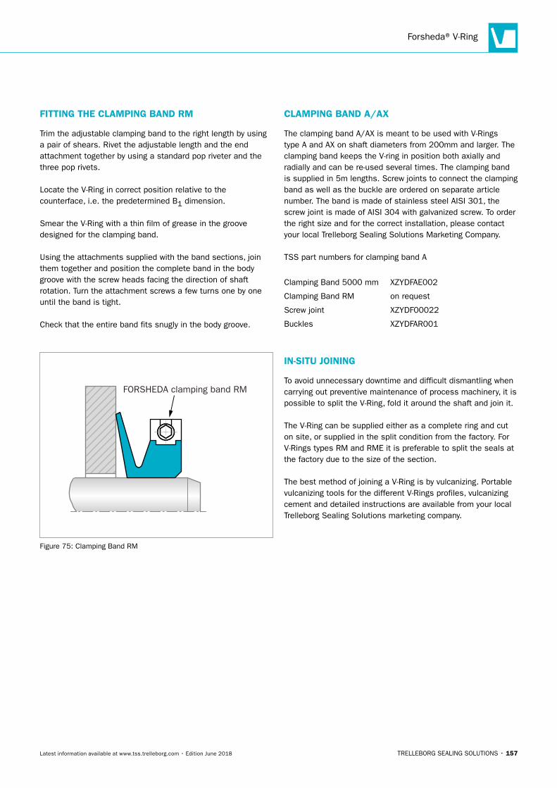
Forsheda® V-Ring
TRELLEBORG SEALING SOLUTIONS • 157Latest information available at www.tss.trelleborg.com • Edition June 2018
FITTING THE CLAMPING BAND RM
Trim the adjustable clamping band to the right length by using a pair of shears. Rivet the adjustable length and the end attachment together by using a standard pop riveter and the three pop rivets.
Locate the V-Ring in correct position relative to the counterface, i.e. the predetermined B1 dimension.
Smear the V-Ring with a thin film of grease in the groove designed for the clamping band.
Using the attachments supplied with the band sections, join them together and position the complete band in the body groove with the screw heads facing the direction of shaft rotation. Turn the attachment screws a few turns one by one until the band is tight.
Check that the entire band fits snugly in the body groove.
FORSHEDA clamping band RM
Figure 75: Clamping Band RM
CLAMPING BAND A/AX
The clamping band A/AX is meant to be used with V-Rings type A and AX on shaft diameters from 200mm and larger. The clamping band keeps the V-ring in position both axially and radially and can be re-used several times. The clamping band is supplied in 5m lengths. Screw joints to connect the clamping band as well as the buckle are ordered on separate article number. The band is made of stainless steel AISI 301, the screw joint is made of AISI 304 with galvanized screw. To order the right size and for the correct installation, please contact your local Trelleborg Sealing Solutions Marketing Company.
TSS part numbers for clamping band A
Clamping Band 5000 mm XZYDFAE002
Clamping Band RM on request
Screw joint XZYDF00022
Buckles XZYDFAR001
IN-SITU JOINING
To avoid unnecessary downtime and difficult dismantling when carrying out preventive maintenance of process machinery, it is possible to split the V-Ring, fold it around the shaft and join it.
The V-Ring can be supplied either as a complete ring and cut on site, or supplied in the split condition from the factory. For V-Rings types RM and RME it is preferable to split the seals at the factory due to the size of the section.
The best method of joining a V-Ring is by vulcanizing. Portable vulcanizing tools for the different V-Rings profiles, vulcanizing cement and detailed instructions are available from your local Trelleborg Sealing Solutions marketing company.
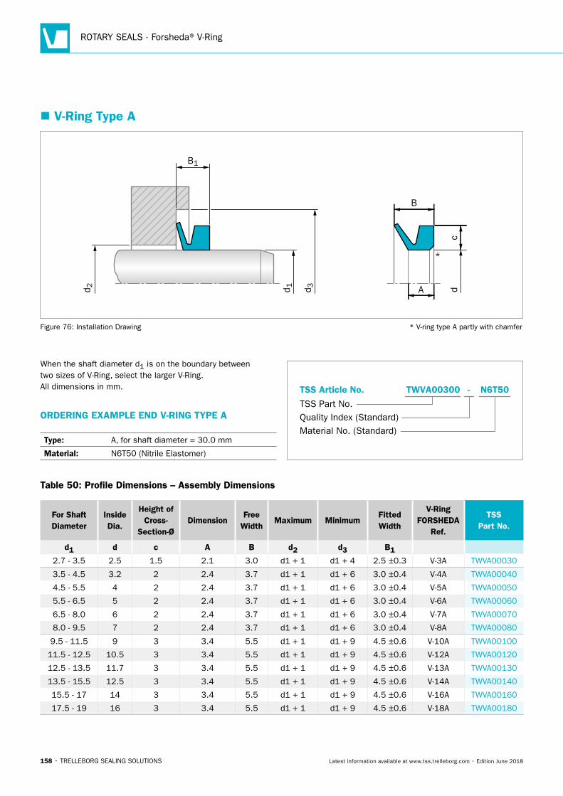
ROTARY SEALS · Forsheda® V-Ring
158 • TRELLEBORG SEALING SOLUTIONS Latest information available at www.tss.trelleborg.com • Edition June 2018
� V-Ring Type A
B
d 3d 1 dd 2
B1
A
*
c
Figure 76: Installation Drawing * V-ring type A partly with chamfer
Table 50: Profile Dimensions – Assembly Dimensions
For Shaft Diameter
Inside Dia.
Height of Cross-
Section-ØDimension
Free Width
Maximum MinimumFitted Width
V-Ring FORSHEDA
Ref.
TSS Part No.
d1 d c A B d2 d3 B12.7 - 3.5 2.5 1.5 2.1 3.0 d1 + 1 d1 + 4 2.5 ±0.3 V-3A TWVA00030
3.5 - 4.5 3.2 2 2.4 3.7 d1 + 1 d1 + 6 3.0 ±0.4 V-4A TWVA00040
4.5 - 5.5 4 2 2.4 3.7 d1 + 1 d1 + 6 3.0 ±0.4 V-5A TWVA00050
5.5 - 6.5 5 2 2.4 3.7 d1 + 1 d1 + 6 3.0 ±0.4 V-6A TWVA00060
6.5 - 8.0 6 2 2.4 3.7 d1 + 1 d1 + 6 3.0 ±0.4 V-7A TWVA00070
8.0 - 9.5 7 2 2.4 3.7 d1 + 1 d1 + 6 3.0 ±0.4 V-8A TWVA00080
9.5 - 11.5 9 3 3.4 5.5 d1 + 1 d1 + 9 4.5 ±0.6 V-10A TWVA00100
11.5 - 12.5 10.5 3 3.4 5.5 d1 + 1 d1 + 9 4.5 ±0.6 V-12A TWVA00120
12.5 - 13.5 11.7 3 3.4 5.5 d1 + 1 d1 + 9 4.5 ±0.6 V-13A TWVA00130
13.5 - 15.5 12.5 3 3.4 5.5 d1 + 1 d1 + 9 4.5 ±0.6 V-14A TWVA00140
15.5 - 17 14 3 3.4 5.5 d1 + 1 d1 + 9 4.5 ±0.6 V-16A TWVA00160
17.5 - 19 16 3 3.4 5.5 d1 + 1 d1 + 9 4.5 ±0.6 V-18A TWVA00180
When the shaft diameter d1 is on the boundary between two sizes of V-Ring, select the larger V-Ring. All dimensions in mm.
ORDERING EXAMPLE END V-RING TYPE A
Type: A, for shaft diameter = 30.0 mm
Material: N6T50 (Nitrile Elastomer)
Material No. (Standard)
TSS Part No.
TSS Article No. N6T50TWVA00300 -
Quality Index (Standard)
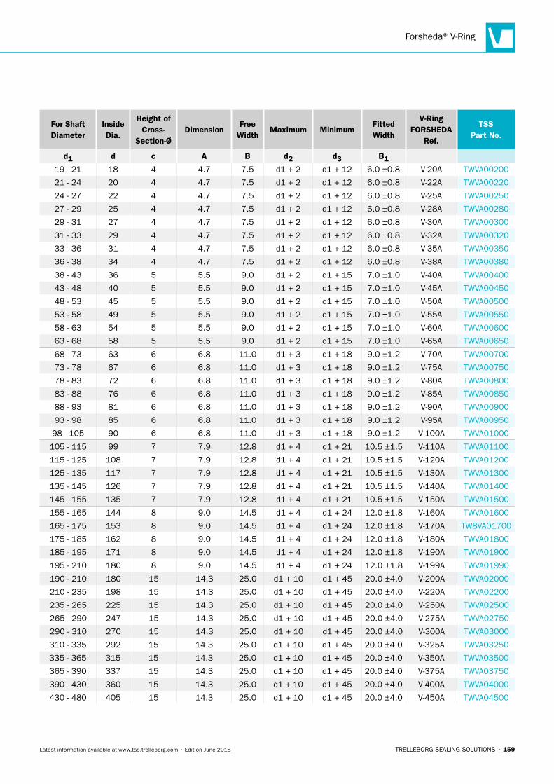
Forsheda® V-Ring
TRELLEBORG SEALING SOLUTIONS • 159Latest information available at www.tss.trelleborg.com • Edition June 2018
For Shaft Diameter
Inside Dia.
Height of Cross-
Section-ØDimension
Free Width
Maximum MinimumFitted Width
V-Ring FORSHEDA
Ref.
TSS Part No.
d1 d c A B d2 d3 B119 - 21 18 4 4.7 7.5 d1 + 2 d1 + 12 6.0 ±0.8 V-20A TWVA00200
21 - 24 20 4 4.7 7.5 d1 + 2 d1 + 12 6.0 ±0.8 V-22A TWVA00220
24 - 27 22 4 4.7 7.5 d1 + 2 d1 + 12 6.0 ±0.8 V-25A TWVA00250
27 - 29 25 4 4.7 7.5 d1 + 2 d1 + 12 6.0 ±0.8 V-28A TWVA00280
29 - 31 27 4 4.7 7.5 d1 + 2 d1 + 12 6.0 ±0.8 V-30A TWVA00300
31 - 33 29 4 4.7 7.5 d1 + 2 d1 + 12 6.0 ±0.8 V-32A TWVA00320
33 - 36 31 4 4.7 7.5 d1 + 2 d1 + 12 6.0 ±0.8 V-35A TWVA00350
36 - 38 34 4 4.7 7.5 d1 + 2 d1 + 12 6.0 ±0.8 V-38A TWVA00380
38 - 43 36 5 5.5 9.0 d1 + 2 d1 + 15 7.0 ±1.0 V-40A TWVA00400
43 - 48 40 5 5.5 9.0 d1 + 2 d1 + 15 7.0 ±1.0 V-45A TWVA00450
48 - 53 45 5 5.5 9.0 d1 + 2 d1 + 15 7.0 ±1.0 V-50A TWVA00500
53 - 58 49 5 5.5 9.0 d1 + 2 d1 + 15 7.0 ±1.0 V-55A TWVA00550
58 - 63 54 5 5.5 9.0 d1 + 2 d1 + 15 7.0 ±1.0 V-60A TWVA00600
63 - 68 58 5 5.5 9.0 d1 + 2 d1 + 15 7.0 ±1.0 V-65A TWVA00650
68 - 73 63 6 6.8 11.0 d1 + 3 d1 + 18 9.0 ±1.2 V-70A TWVA00700
73 - 78 67 6 6.8 11.0 d1 + 3 d1 + 18 9.0 ±1.2 V-75A TWVA00750
78 - 83 72 6 6.8 11.0 d1 + 3 d1 + 18 9.0 ±1.2 V-80A TWVA00800
83 - 88 76 6 6.8 11.0 d1 + 3 d1 + 18 9.0 ±1.2 V-85A TWVA00850
88 - 93 81 6 6.8 11.0 d1 + 3 d1 + 18 9.0 ±1.2 V-90A TWVA00900
93 - 98 85 6 6.8 11.0 d1 + 3 d1 + 18 9.0 ±1.2 V-95A TWVA00950
98 - 105 90 6 6.8 11.0 d1 + 3 d1 + 18 9.0 ±1.2 V-100A TWVA01000
105 - 115 99 7 7.9 12.8 d1 + 4 d1 + 21 10.5 ±1.5 V-110A TWVA01100
115 - 125 108 7 7.9 12.8 d1 + 4 d1 + 21 10.5 ±1.5 V-120A TWVA01200
125 - 135 117 7 7.9 12.8 d1 + 4 d1 + 21 10.5 ±1.5 V-130A TWVA01300
135 - 145 126 7 7.9 12.8 d1 + 4 d1 + 21 10.5 ±1.5 V-140A TWVA01400
145 - 155 135 7 7.9 12.8 d1 + 4 d1 + 21 10.5 ±1.5 V-150A TWVA01500
155 - 165 144 8 9.0 14.5 d1 + 4 d1 + 24 12.0 ±1.8 V-160A TWVA01600
165 - 175 153 8 9.0 14.5 d1 + 4 d1 + 24 12.0 ±1.8 V-170A TW8VA01700
175 - 185 162 8 9.0 14.5 d1 + 4 d1 + 24 12.0 ±1.8 V-180A TWVA01800
185 - 195 171 8 9.0 14.5 d1 + 4 d1 + 24 12.0 ±1.8 V-190A TWVA01900
195 - 210 180 8 9.0 14.5 d1 + 4 d1 + 24 12.0 ±1.8 V-199A TWVA01990
190 - 210 180 15 14.3 25.0 d1 + 10 d1 + 45 20.0 ±4.0 V-200A TWVA02000
210 - 235 198 15 14.3 25.0 d1 + 10 d1 + 45 20.0 ±4.0 V-220A TWVA02200
235 - 265 225 15 14.3 25.0 d1 + 10 d1 + 45 20.0 ±4.0 V-250A TWVA02500
265 - 290 247 15 14.3 25.0 d1 + 10 d1 + 45 20.0 ±4.0 V-275A TWVA02750
290 - 310 270 15 14.3 25.0 d1 + 10 d1 + 45 20.0 ±4.0 V-300A TWVA03000
310 - 335 292 15 14.3 25.0 d1 + 10 d1 + 45 20.0 ±4.0 V-325A TWVA03250
335 - 365 315 15 14.3 25.0 d1 + 10 d1 + 45 20.0 ±4.0 V-350A TWVA03500
365 - 390 337 15 14.3 25.0 d1 + 10 d1 + 45 20.0 ±4.0 V-375A TWVA03750
390 - 430 360 15 14.3 25.0 d1 + 10 d1 + 45 20.0 ±4.0 V-400A TWVA04000
430 - 480 405 15 14.3 25.0 d1 + 10 d1 + 45 20.0 ±4.0 V-450A TWVA04500
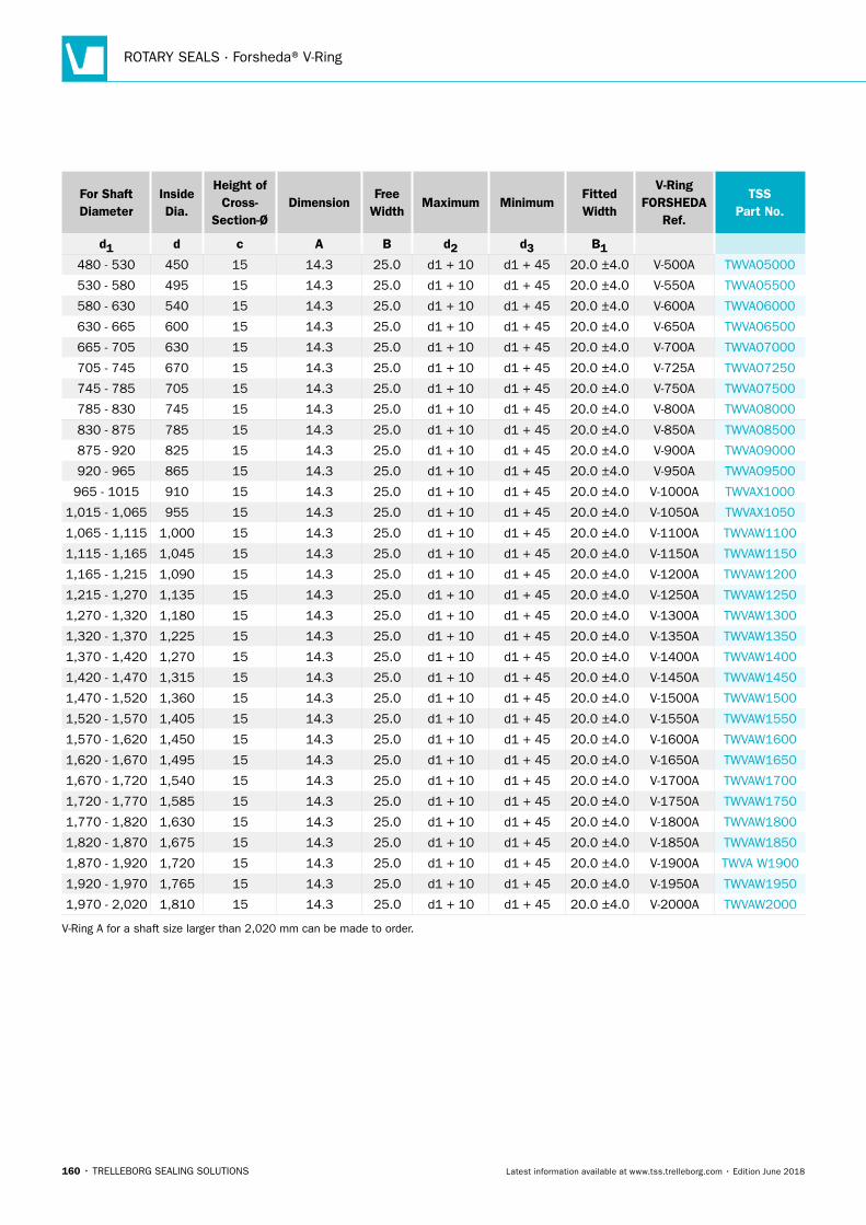
ROTARY SEALS · Forsheda® V-Ring
160 • TRELLEBORG SEALING SOLUTIONS Latest information available at www.tss.trelleborg.com • Edition June 2018
For Shaft Diameter
Inside Dia.
Height of Cross-
Section-ØDimension
Free Width
Maximum MinimumFitted Width
V-Ring FORSHEDA
Ref.
TSS Part No.
d1 d c A B d2 d3 B1480 - 530 450 15 14.3 25.0 d1 + 10 d1 + 45 20.0 ±4.0 V-500A TWVA05000
530 - 580 495 15 14.3 25.0 d1 + 10 d1 + 45 20.0 ±4.0 V-550A TWVA05500
580 - 630 540 15 14.3 25.0 d1 + 10 d1 + 45 20.0 ±4.0 V-600A TWVA06000
630 - 665 600 15 14.3 25.0 d1 + 10 d1 + 45 20.0 ±4.0 V-650A TWVA06500
665 - 705 630 15 14.3 25.0 d1 + 10 d1 + 45 20.0 ±4.0 V-700A TWVA07000
705 - 745 670 15 14.3 25.0 d1 + 10 d1 + 45 20.0 ±4.0 V-725A TWVA07250
745 - 785 705 15 14.3 25.0 d1 + 10 d1 + 45 20.0 ±4.0 V-750A TWVA07500
785 - 830 745 15 14.3 25.0 d1 + 10 d1 + 45 20.0 ±4.0 V-800A TWVA08000
830 - 875 785 15 14.3 25.0 d1 + 10 d1 + 45 20.0 ±4.0 V-850A TWVA08500
875 - 920 825 15 14.3 25.0 d1 + 10 d1 + 45 20.0 ±4.0 V-900A TWVA09000
920 - 965 865 15 14.3 25.0 d1 + 10 d1 + 45 20.0 ±4.0 V-950A TWVA09500
965 - 1015 910 15 14.3 25.0 d1 + 10 d1 + 45 20.0 ±4.0 V-1000A TWVAX1000
1,015 - 1,065 955 15 14.3 25.0 d1 + 10 d1 + 45 20.0 ±4.0 V-1050A TWVAX1050
1,065 - 1,115 1,000 15 14.3 25.0 d1 + 10 d1 + 45 20.0 ±4.0 V-1100A TWVAW1100
1,115 - 1,165 1,045 15 14.3 25.0 d1 + 10 d1 + 45 20.0 ±4.0 V-1150A TWVAW1150
1,165 - 1,215 1,090 15 14.3 25.0 d1 + 10 d1 + 45 20.0 ±4.0 V-1200A TWVAW1200
1,215 - 1,270 1,135 15 14.3 25.0 d1 + 10 d1 + 45 20.0 ±4.0 V-1250A TWVAW1250
1,270 - 1,320 1,180 15 14.3 25.0 d1 + 10 d1 + 45 20.0 ±4.0 V-1300A TWVAW1300
1,320 - 1,370 1,225 15 14.3 25.0 d1 + 10 d1 + 45 20.0 ±4.0 V-1350A TWVAW1350
1,370 - 1,420 1,270 15 14.3 25.0 d1 + 10 d1 + 45 20.0 ±4.0 V-1400A TWVAW1400
1,420 - 1,470 1,315 15 14.3 25.0 d1 + 10 d1 + 45 20.0 ±4.0 V-1450A TWVAW1450
1,470 - 1,520 1,360 15 14.3 25.0 d1 + 10 d1 + 45 20.0 ±4.0 V-1500A TWVAW1500
1,520 - 1,570 1,405 15 14.3 25.0 d1 + 10 d1 + 45 20.0 ±4.0 V-1550A TWVAW1550
1,570 - 1,620 1,450 15 14.3 25.0 d1 + 10 d1 + 45 20.0 ±4.0 V-1600A TWVAW1600
1,620 - 1,670 1,495 15 14.3 25.0 d1 + 10 d1 + 45 20.0 ±4.0 V-1650A TWVAW1650
1,670 - 1,720 1,540 15 14.3 25.0 d1 + 10 d1 + 45 20.0 ±4.0 V-1700A TWVAW1700
1,720 - 1,770 1,585 15 14.3 25.0 d1 + 10 d1 + 45 20.0 ±4.0 V-1750A TWVAW1750
1,770 - 1,820 1,630 15 14.3 25.0 d1 + 10 d1 + 45 20.0 ±4.0 V-1800A TWVAW1800
1,820 - 1,870 1,675 15 14.3 25.0 d1 + 10 d1 + 45 20.0 ±4.0 V-1850A TWVAW1850
1,870 - 1,920 1,720 15 14.3 25.0 d1 + 10 d1 + 45 20.0 ±4.0 V-1900A TWVA W1900
1,920 - 1,970 1,765 15 14.3 25.0 d1 + 10 d1 + 45 20.0 ±4.0 V-1950A TWVAW1950
1,970 - 2,020 1,810 15 14.3 25.0 d1 + 10 d1 + 45 20.0 ±4.0 V-2000A TWVAW2000
V-Ring A for a shaft size larger than 2,020 mm can be made to order.
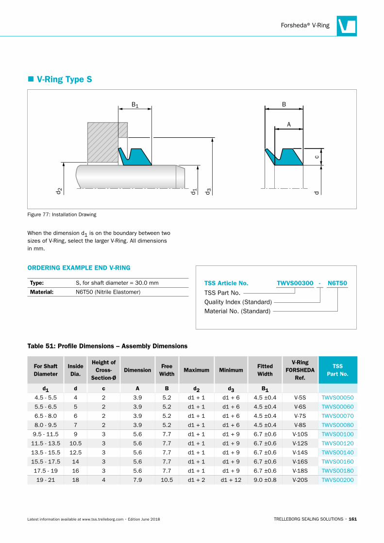
Forsheda® V-Ring
TRELLEBORG SEALING SOLUTIONS • 161Latest information available at www.tss.trelleborg.com • Edition June 2018
� V-Ring Type S
d 3d 1
B
dd 2
B1
A
c
Figure 77: Installation Drawing
When the dimension d1 is on the boundary between two sizes of V-Ring, select the larger V-Ring. All dimensions in mm.
ORDERING EXAMPLE END V-RING
Type: S, for shaft diameter = 30.0 mm
Material: N6T50 (Nitrile Elastomer)
Material No. (Standard)
TSS Part No.
TSS Article No. TWVS00300 N6T50-
Quality Index (Standard)
Table 51: Profile Dimensions – Assembly Dimensions
For Shaft Diameter
InsideDia.
Height ofCross-
Section-ØDimension
FreeWidth
Maximum MinimumFittedWidth
V-RingFORSHEDA
Ref.
TSS Part No.
d1 d c A B d2 d3 B14.5 - 5.5 4 2 3.9 5.2 d1 + 1 d1 + 6 4.5 ±0.4 V-5S TWVS00050
5.5 - 6.5 5 2 3.9 5.2 d1 + 1 d1 + 6 4.5 ±0.4 V-6S TWVS00060
6.5 - 8.0 6 2 3.9 5.2 d1 + 1 d1 + 6 4.5 ±0.4 V-7S TWVS00070
8.0 - 9.5 7 2 3.9 5.2 d1 + 1 d1 + 6 4.5 ±0.4 V-8S TWVS00080
9.5 - 11.5 9 3 5.6 7.7 d1 + 1 d1 + 9 6.7 ±0.6 V-10S TWVS00100
11.5 - 13.5 10.5 3 5.6 7.7 d1 + 1 d1 + 9 6.7 ±0.6 V-12S TWVS00120
13.5 - 15.5 12.5 3 5.6 7.7 d1 + 1 d1 + 9 6.7 ±0.6 V-14S TWVS00140
15.5 - 17.5 14 3 5.6 7.7 d1 + 1 d1 + 9 6.7 ±0.6 V-16S TWVS00160
17.5 - 19 16 3 5.6 7.7 d1 + 1 d1 + 9 6.7 ±0.6 V-18S TWVS00180
19 - 21 18 4 7.9 10.5 d1 + 2 d1 + 12 9.0 ±0.8 V-20S TWVS00200
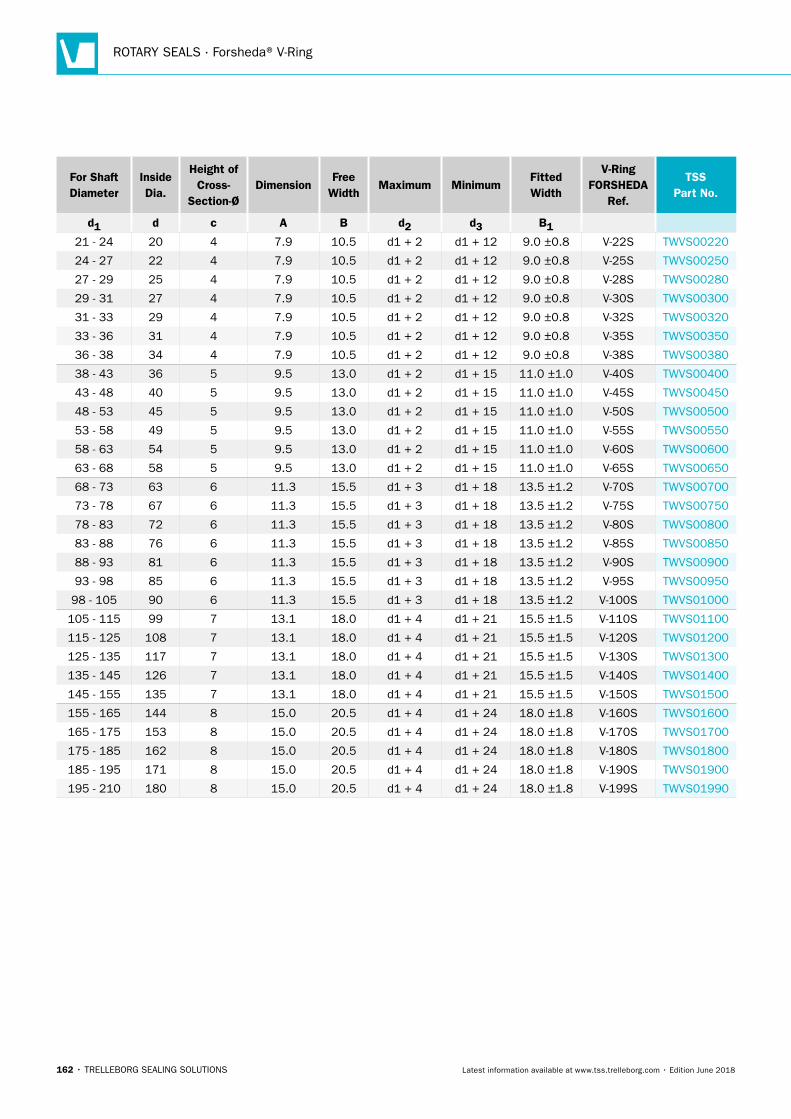
ROTARY SEALS · Forsheda® V-Ring
162 • TRELLEBORG SEALING SOLUTIONS Latest information available at www.tss.trelleborg.com • Edition June 2018
For Shaft Diameter
InsideDia.
Height ofCross-
Section-ØDimension
FreeWidth
Maximum MinimumFittedWidth
V-RingFORSHEDA
Ref.
TSS Part No.
d1 d c A B d2 d3 B121 - 24 20 4 7.9 10.5 d1 + 2 d1 + 12 9.0 ±0.8 V-22S TWVS00220
24 - 27 22 4 7.9 10.5 d1 + 2 d1 + 12 9.0 ±0.8 V-25S TWVS00250
27 - 29 25 4 7.9 10.5 d1 + 2 d1 + 12 9.0 ±0.8 V-28S TWVS00280
29 - 31 27 4 7.9 10.5 d1 + 2 d1 + 12 9.0 ±0.8 V-30S TWVS00300
31 - 33 29 4 7.9 10.5 d1 + 2 d1 + 12 9.0 ±0.8 V-32S TWVS00320
33 - 36 31 4 7.9 10.5 d1 + 2 d1 + 12 9.0 ±0.8 V-35S TWVS00350
36 - 38 34 4 7.9 10.5 d1 + 2 d1 + 12 9.0 ±0.8 V-38S TWVS00380
38 - 43 36 5 9.5 13.0 d1 + 2 d1 + 15 11.0 ±1.0 V-40S TWVS00400
43 - 48 40 5 9.5 13.0 d1 + 2 d1 + 15 11.0 ±1.0 V-45S TWVS00450
48 - 53 45 5 9.5 13.0 d1 + 2 d1 + 15 11.0 ±1.0 V-50S TWVS00500
53 - 58 49 5 9.5 13.0 d1 + 2 d1 + 15 11.0 ±1.0 V-55S TWVS00550
58 - 63 54 5 9.5 13.0 d1 + 2 d1 + 15 11.0 ±1.0 V-60S TWVS00600
63 - 68 58 5 9.5 13.0 d1 + 2 d1 + 15 11.0 ±1.0 V-65S TWVS00650
68 - 73 63 6 11.3 15.5 d1 + 3 d1 + 18 13.5 ±1.2 V-70S TWVS00700
73 - 78 67 6 11.3 15.5 d1 + 3 d1 + 18 13.5 ±1.2 V-75S TWVS00750
78 - 83 72 6 11.3 15.5 d1 + 3 d1 + 18 13.5 ±1.2 V-80S TWVS00800
83 - 88 76 6 11.3 15.5 d1 + 3 d1 + 18 13.5 ±1.2 V-85S TWVS00850
88 - 93 81 6 11.3 15.5 d1 + 3 d1 + 18 13.5 ±1.2 V-90S TWVS00900
93 - 98 85 6 11.3 15.5 d1 + 3 d1 + 18 13.5 ±1.2 V-95S TWVS00950
98 - 105 90 6 11.3 15.5 d1 + 3 d1 + 18 13.5 ±1.2 V-100S TWVS01000
105 - 115 99 7 13.1 18.0 d1 + 4 d1 + 21 15.5 ±1.5 V-110S TWVS01100
115 - 125 108 7 13.1 18.0 d1 + 4 d1 + 21 15.5 ±1.5 V-120S TWVS01200
125 - 135 117 7 13.1 18.0 d1 + 4 d1 + 21 15.5 ±1.5 V-130S TWVS01300
135 - 145 126 7 13.1 18.0 d1 + 4 d1 + 21 15.5 ±1.5 V-140S TWVS01400
145 - 155 135 7 13.1 18.0 d1 + 4 d1 + 21 15.5 ±1.5 V-150S TWVS01500
155 - 165 144 8 15.0 20.5 d1 + 4 d1 + 24 18.0 ±1.8 V-160S TWVS01600
165 - 175 153 8 15.0 20.5 d1 + 4 d1 + 24 18.0 ±1.8 V-170S TWVS01700
175 - 185 162 8 15.0 20.5 d1 + 4 d1 + 24 18.0 ±1.8 V-180S TWVS01800
185 - 195 171 8 15.0 20.5 d1 + 4 d1 + 24 18.0 ±1.8 V-190S TWVS01900
195 - 210 180 8 15.0 20.5 d1 + 4 d1 + 24 18.0 ±1.8 V-199S TWVS01990
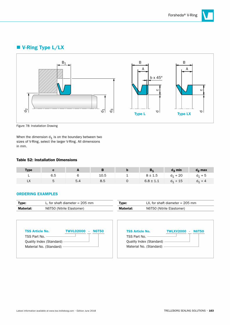
Forsheda® V-Ring
TRELLEBORG SEALING SOLUTIONS • 163Latest information available at www.tss.trelleborg.com • Edition June 2018
� V-Ring Type L/LX
Type L Type LXd 3d 1
B
d 2
B1
A
B
d
A
b x 45°
c
dc
Figure 78: Installation Drawing
When the dimension d1 is on the boundary between two sizes of V-Ring, select the larger V-Ring. All dimensions in mm.
Table 52: Installation Dimensions
Type c A B b B1 d3 min d2 max
L 6.5 6 10.5 1 8 ± 1.5 d1 + 20 d1 + 5
LX 5 5.4 8.5 0 6.8 ± 1.1 d1 + 15 d1 + 4
ORDERING EXAMPLES
Type: L, for shaft diameter = 205 mm
Material: N6T50 (Nitrile Elastomer)
Quality Index (Standard)TSS Part No.
TSS Article No. TWVL02000 N6T50-
Material No. (Standard)
Type: LX, for shaft diameter = 205 mm
Material: N6T50 (Nitrile Elastomer)
Material No. (Standard)
TSS Part No.
TSS Article No. TWLXV2000 N6T50-
Quality Index (Standard)
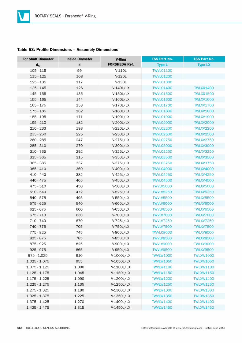
ROTARY SEALS · Forsheda® V-Ring
164 • TRELLEBORG SEALING SOLUTIONS Latest information available at www.tss.trelleborg.com • Edition June 2018
Table 53: Profile Dimensions – Assembly Dimensions
For Shaft Diameter Inside Diameter V-RingFORSHEDA Ref.
TSS Part No. TSS Part No.
d1 d Type L Type LX
105 - 115 99 V-110L TWVL01100
115 - 125 108 V-120L TWVL01200
125 - 135 117 V-130L TWVL01300
135 - 145 126 V-140L/LX TWVL01400 TWLX01400
145 - 155 135 V-150L/LX TWVL01500 TWLX01500
155 - 165 144 V-160L/LX TWVL01600 TWLXV1600
165 - 175 153 V-170L/LX TWVL01700 TWLXV1700
175 - 185 162 V-180L/LX TWVL01800 TWLXV1800
185 - 195 171 V-190L/LX TWVL01900 TWLXV1900
195 - 210 182 V-200L/LX TWVL02000 TWLXV2000
210 - 233 198 V-220L/LX TWVL02200 TWLXV2200
233 - 260 225 V-250L/LX TWVL02500 TWLXV2500
260 - 285 247 V-275L/LX TWVL02750 TWLXV2750
285 - 310 270 V-300L/LX TWVL03000 TWLXV3000
310 - 335 292 V-325L/LX TWVL03250 TWLXV3250
335 - 365 315 V-350L/LX TWVL03500 TWLXV3500
365 - 385 337 V-375L/LX TWVL03750 TWLXV3750
385 - 410 360 V-400L/LX TWVL04000 TWLXV4000
410 - 440 382 V-425L/LX TWVL04250 TWLXV4250
440 - 475 405 V-450L/LX TWVL04500 TWLXV4500
475 - 510 450 V-500L/LX TWVLV5000 TWLXV5000
510 - 540 472 V-525L/LX TWVLV5250 TWLXV5250
540 - 575 495 V-550L/LX TWVLV5500 TWLXV5500
575 - 625 540 V-600L/LX TWVLV6000 TWLXV6000
625 - 675 600 V-650L/LX TWVLV6500 TWLXV6500
675 - 710 630 V-700L/LX TWVLV7000 TWLXV7000
710 - 740 670 V-725L/LX TWVLV7250 TWLXV7250
740 - 775 705 V-750L/LX TWVLV7500 TWLXV7500
775 - 825 745 V-800L/LX TWVL08000 TWLXV8000
825 - 875 785 V-850L/LX TWVLV8500 TWLXV8500
875 - 925 825 V-900L/LX TWVLV9000 TWLXV9000
925 - 975 865 V-950L/LX TWVLV9500 TWLXV9500
975 - 1,025 910 V-1000L/LX TWVLW1000 TWLXW1000
1,025 - 1,075 955 V-1050L/LX TWVLW1050 TWLXW1050
1,075 - 1,125 1,000 V-1100L/LX TWVLW1100 TWLXW1100
1,125 - 1,175 1,045 V-1150L/LX TWVLW1150 TWLXW1150
1,175 - 1,225 1,090 V-1200L/LX TWVLW1200 TWLXW1200
1,225 - 1,275 1,135 V-1250L/LX TWVLW1250 TWLXW1250
1,275 - 1,325 1,180 V-1300L/LX TWVLW1300 TWLXW1300
1,325 - 1,375 1,225 V-1350L/LX TWVLW1350 TWLXW1350
1,375 - 1,425 1,270 V-1400L/LX TWVLW1400 TWLXW1400
1,425 - 1,475 1,315 V-1450L/LX TWVLW1450 TWLXW1450
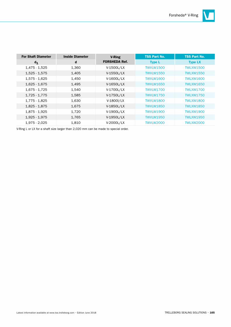
Forsheda® V-Ring
TRELLEBORG SEALING SOLUTIONS • 165Latest information available at www.tss.trelleborg.com • Edition June 2018
For Shaft Diameter Inside Diameter V-RingFORSHEDA Ref.
TSS Part No. TSS Part No.
d1 d Type L Type LX
1,475 - 1,525 1,360 V-1500L/LX TWVLW1500 TWLXW1500
1,525 - 1,575 1,405 V-1550L/LX TWVLW1550 TWLXW1550
1,575 - 1,625 1,450 V-1600L/LX TWVLW1600 TWLXW1600
1,625 - 1,675 1,495 V-1650L/LX TWVLW1650 TWLXW1650
1,675 - 1,725 1,540 V-1700L/LX TWVLW1700 TWLXW1700
1,725 - 1,775 1,585 V-1750L/LX TWVLW1750 TWLXW1750
1,775 - 1,825 1,630 V-1800l/LX TWVLW1800 TWLXW1800
1,825 - 1,875 1,675 V-1850L/LX TWVLW1850 TWLXW1850
1,875 - 1,925 1,720 V-1900L/LX TWVLW1900 TWLXW1900
1,925 - 1,975 1,765 V-1950L/LX TWVLW1950 TWLXW1950
1,975 - 2,025 1,810 V-2000L/LX TWVLW2000 TWLXW2000
V-Ring L or LX for a shaft size larger than 2,020 mm can be made to special order.
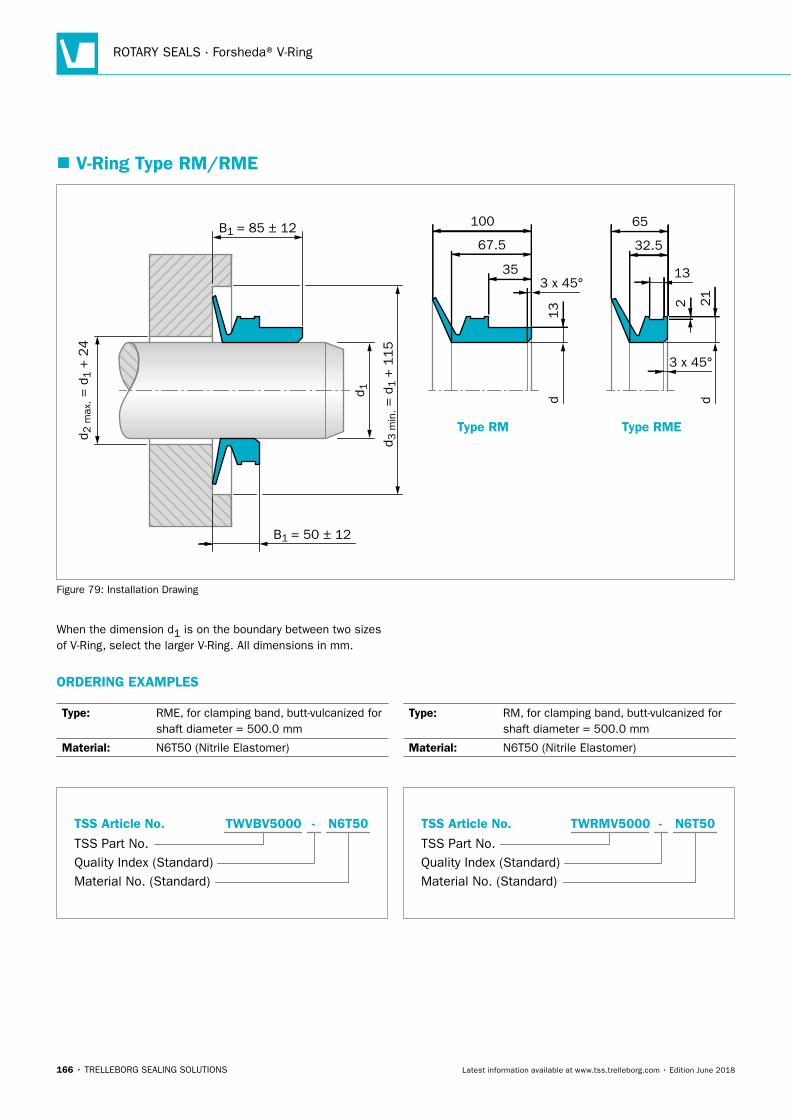
ROTARY SEALS · Forsheda® V-Ring
166 • TRELLEBORG SEALING SOLUTIONS Latest information available at www.tss.trelleborg.com • Edition June 2018
� V-Ring Type RM/RME
Type RM Type RME
100
d
67.5
353 x 45°
13
65
d
32.5
21
2
13
3 x 45°d 1
B1 = 85 ± 12
B1 = 50 ± 12
d 3 m
in. =
d1 +
115
d 2 m
ax. =
d1 +
24
Figure 79: Installation Drawing
When the dimension d1 is on the boundary between two sizes of V-Ring, select the larger V-Ring. All dimensions in mm.
ORDERING EXAMPLES
Type: RME, for clamping band, butt-vulcanized for shaft diameter = 500.0 mm
Material: N6T50 (Nitrile Elastomer)
Material No. (Standard)
TSS Part No.
TSS Article No. TWVBV5000 N6T50-
Quality Index (Standard)
Type: RM, for clamping band, butt-vulcanized for shaft diameter = 500.0 mm
Material: N6T50 (Nitrile Elastomer)
Quality Index (Standard)TSS Part No.
TSS Article No. TWRMV5000 N6T50-
Material No. (Standard)
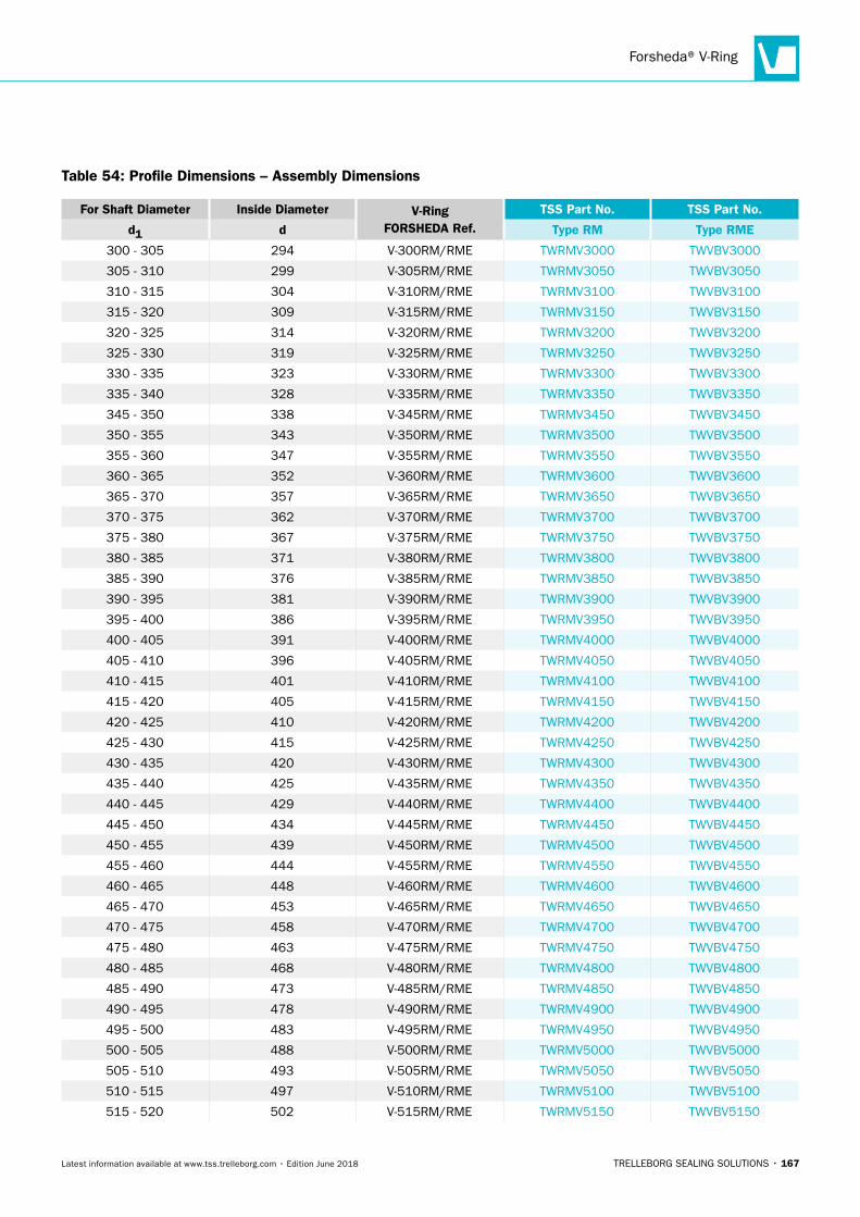
Forsheda® V-Ring
TRELLEBORG SEALING SOLUTIONS • 167Latest information available at www.tss.trelleborg.com • Edition June 2018
Table 54: Profile Dimensions – Assembly Dimensions
For Shaft Diameter Inside Diameter V-RingFORSHEDA Ref.
TSS Part No. TSS Part No.
d1 d Type RM Type RME
300 - 305 294 V-300RM/RME TWRMV3000 TWVBV3000
305 - 310 299 V-305RM/RME TWRMV3050 TWVBV3050
310 - 315 304 V-310RM/RME TWRMV3100 TWVBV3100
315 - 320 309 V-315RM/RME TWRMV3150 TWVBV3150
320 - 325 314 V-320RM/RME TWRMV3200 TWVBV3200
325 - 330 319 V-325RM/RME TWRMV3250 TWVBV3250
330 - 335 323 V-330RM/RME TWRMV3300 TWVBV3300
335 - 340 328 V-335RM/RME TWRMV3350 TWVBV3350
345 - 350 338 V-345RM/RME TWRMV3450 TWVBV3450
350 - 355 343 V-350RM/RME TWRMV3500 TWVBV3500
355 - 360 347 V-355RM/RME TWRMV3550 TWVBV3550
360 - 365 352 V-360RM/RME TWRMV3600 TWVBV3600
365 - 370 357 V-365RM/RME TWRMV3650 TWVBV3650
370 - 375 362 V-370RM/RME TWRMV3700 TWVBV3700
375 - 380 367 V-375RM/RME TWRMV3750 TWVBV3750
380 - 385 371 V-380RM/RME TWRMV3800 TWVBV3800
385 - 390 376 V-385RM/RME TWRMV3850 TWVBV3850
390 - 395 381 V-390RM/RME TWRMV3900 TWVBV3900
395 - 400 386 V-395RM/RME TWRMV3950 TWVBV3950
400 - 405 391 V-400RM/RME TWRMV4000 TWVBV4000
405 - 410 396 V-405RM/RME TWRMV4050 TWVBV4050
410 - 415 401 V-410RM/RME TWRMV4100 TWVBV4100
415 - 420 405 V-415RM/RME TWRMV4150 TWVBV4150
420 - 425 410 V-420RM/RME TWRMV4200 TWVBV4200
425 - 430 415 V-425RM/RME TWRMV4250 TWVBV4250
430 - 435 420 V-430RM/RME TWRMV4300 TWVBV4300
435 - 440 425 V-435RM/RME TWRMV4350 TWVBV4350
440 - 445 429 V-440RM/RME TWRMV4400 TWVBV4400
445 - 450 434 V-445RM/RME TWRMV4450 TWVBV4450
450 - 455 439 V-450RM/RME TWRMV4500 TWVBV4500
455 - 460 444 V-455RM/RME TWRMV4550 TWVBV4550
460 - 465 448 V-460RM/RME TWRMV4600 TWVBV4600
465 - 470 453 V-465RM/RME TWRMV4650 TWVBV4650
470 - 475 458 V-470RM/RME TWRMV4700 TWVBV4700
475 - 480 463 V-475RM/RME TWRMV4750 TWVBV4750
480 - 485 468 V-480RM/RME TWRMV4800 TWVBV4800
485 - 490 473 V-485RM/RME TWRMV4850 TWVBV4850
490 - 495 478 V-490RM/RME TWRMV4900 TWVBV4900
495 - 500 483 V-495RM/RME TWRMV4950 TWVBV4950
500 - 505 488 V-500RM/RME TWRMV5000 TWVBV5000
505 - 510 493 V-505RM/RME TWRMV5050 TWVBV5050
510 - 515 497 V-510RM/RME TWRMV5100 TWVBV5100
515 - 520 502 V-515RM/RME TWRMV5150 TWVBV5150
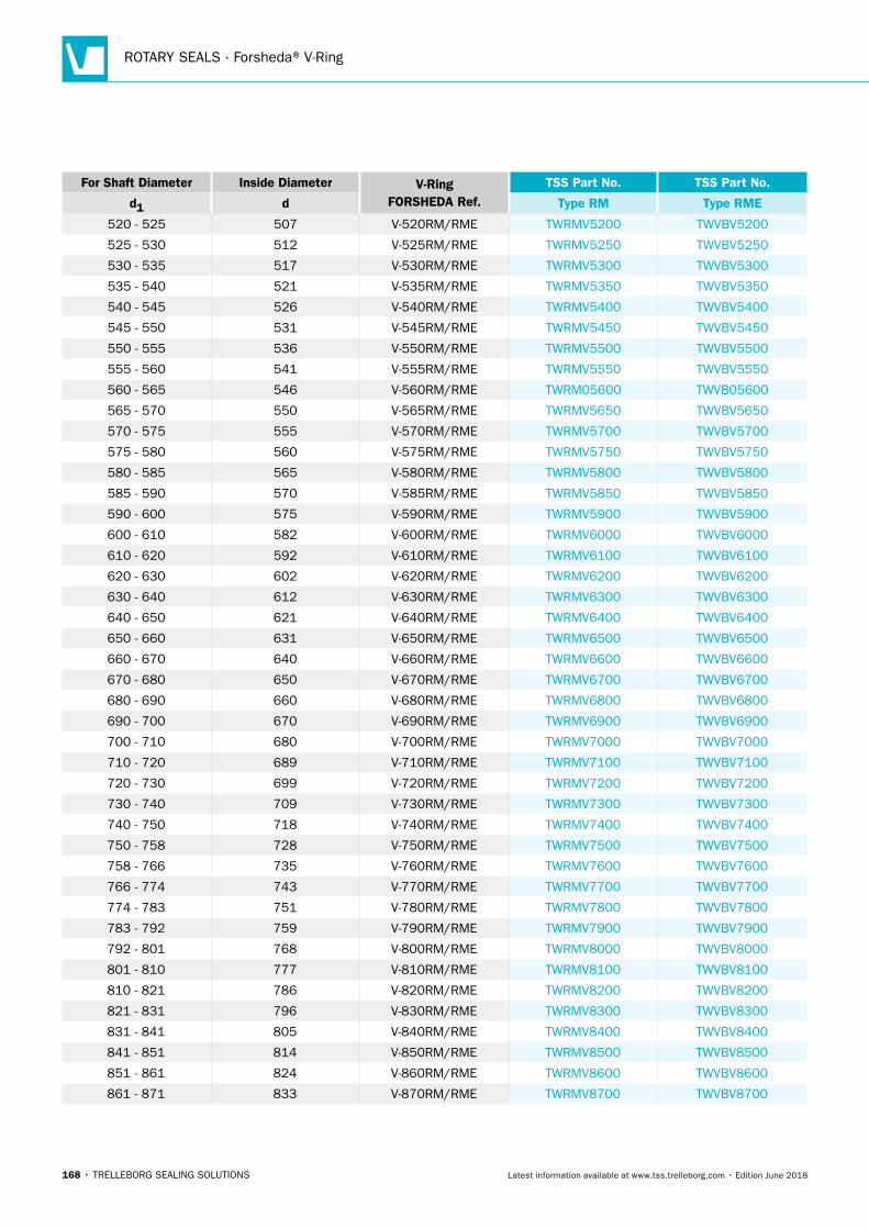
ROTARY SEALS · Forsheda® V-Ring
168 • TRELLEBORG SEALING SOLUTIONS Latest information available at www.tss.trelleborg.com • Edition June 2018
For Shaft Diameter Inside Diameter V-RingFORSHEDA Ref.
TSS Part No. TSS Part No.
d1 d Type RM Type RME
520 - 525 507 V-520RM/RME TWRMV5200 TWVBV5200
525 - 530 512 V-525RM/RME TWRMV5250 TWVBV5250
530 - 535 517 V-530RM/RME TWRMV5300 TWVBV5300
535 - 540 521 V-535RM/RME TWRMV5350 TWVBV5350
540 - 545 526 V-540RM/RME TWRMV5400 TWVBV5400
545 - 550 531 V-545RM/RME TWRMV5450 TWVBV5450
550 - 555 536 V-550RM/RME TWRMV5500 TWVBV5500
555 - 560 541 V-555RM/RME TWRMV5550 TWVBV5550
560 - 565 546 V-560RM/RME TWRM05600 TWVB05600
565 - 570 550 V-565RM/RME TWRMV5650 TWVBV5650
570 - 575 555 V-570RM/RME TWRMV5700 TWVBV5700
575 - 580 560 V-575RM/RME TWRMV5750 TWVBV5750
580 - 585 565 V-580RM/RME TWRMV5800 TWVBV5800
585 - 590 570 V-585RM/RME TWRMV5850 TWVBV5850
590 - 600 575 V-590RM/RME TWRMV5900 TWVBV5900
600 - 610 582 V-600RM/RME TWRMV6000 TWVBV6000
610 - 620 592 V-610RM/RME TWRMV6100 TWVBV6100
620 - 630 602 V-620RM/RME TWRMV6200 TWVBV6200
630 - 640 612 V-630RM/RME TWRMV6300 TWVBV6300
640 - 650 621 V-640RM/RME TWRMV6400 TWVBV6400
650 - 660 631 V-650RM/RME TWRMV6500 TWVBV6500
660 - 670 640 V-660RM/RME TWRMV6600 TWVBV6600
670 - 680 650 V-670RM/RME TWRMV6700 TWVBV6700
680 - 690 660 V-680RM/RME TWRMV6800 TWVBV6800
690 - 700 670 V-690RM/RME TWRMV6900 TWVBV6900
700 - 710 680 V-700RM/RME TWRMV7000 TWVBV7000
710 - 720 689 V-710RM/RME TWRMV7100 TWVBV7100
720 - 730 699 V-720RM/RME TWRMV7200 TWVBV7200
730 - 740 709 V-730RM/RME TWRMV7300 TWVBV7300
740 - 750 718 V-740RM/RME TWRMV7400 TWVBV7400
750 - 758 728 V-750RM/RME TWRMV7500 TWVBV7500
758 - 766 735 V-760RM/RME TWRMV7600 TWVBV7600
766 - 774 743 V-770RM/RME TWRMV7700 TWVBV7700
774 - 783 751 V-780RM/RME TWRMV7800 TWVBV7800
783 - 792 759 V-790RM/RME TWRMV7900 TWVBV7900
792 - 801 768 V-800RM/RME TWRMV8000 TWVBV8000
801 - 810 777 V-810RM/RME TWRMV8100 TWVBV8100
810 - 821 786 V-820RM/RME TWRMV8200 TWVBV8200
821 - 831 796 V-830RM/RME TWRMV8300 TWVBV8300
831 - 841 805 V-840RM/RME TWRMV8400 TWVBV8400
841 - 851 814 V-850RM/RME TWRMV8500 TWVBV8500
851 - 861 824 V-860RM/RME TWRMV8600 TWVBV8600
861 - 871 833 V-870RM/RME TWRMV8700 TWVBV8700
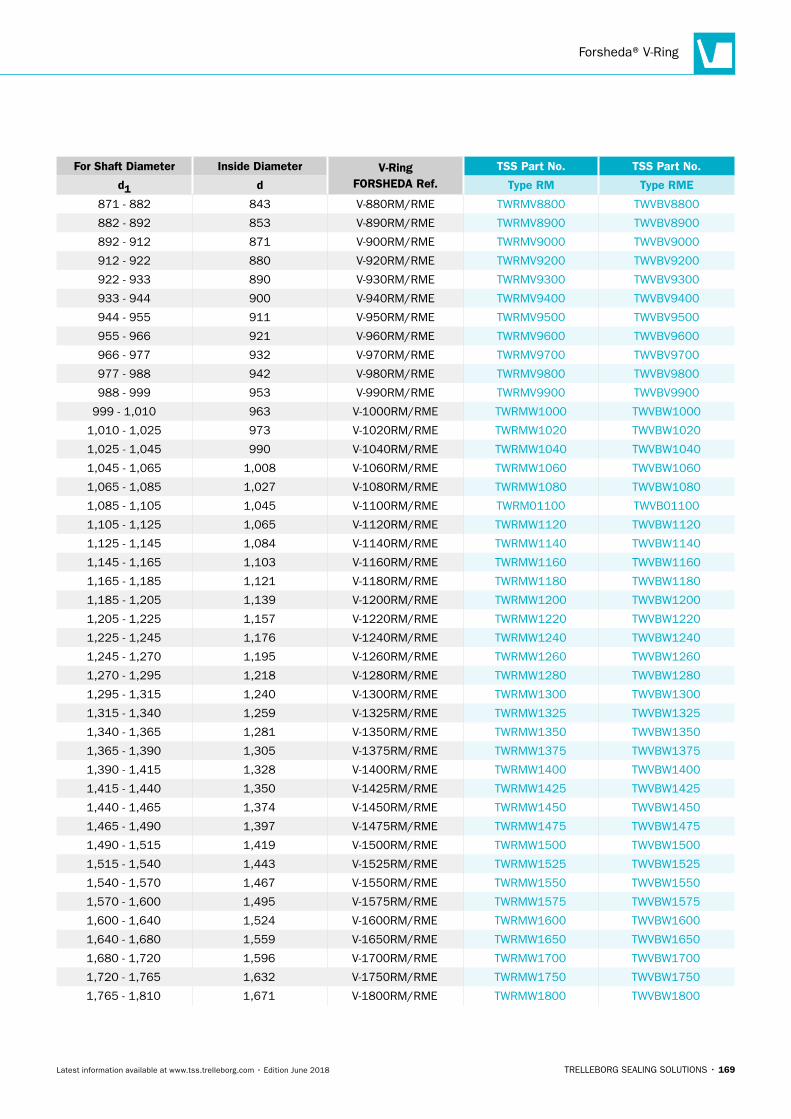
Forsheda® V-Ring
TRELLEBORG SEALING SOLUTIONS • 169Latest information available at www.tss.trelleborg.com • Edition June 2018
For Shaft Diameter Inside Diameter V-RingFORSHEDA Ref.
TSS Part No. TSS Part No.
d1 d Type RM Type RME
871 - 882 843 V-880RM/RME TWRMV8800 TWVBV8800
882 - 892 853 V-890RM/RME TWRMV8900 TWVBV8900
892 - 912 871 V-900RM/RME TWRMV9000 TWVBV9000
912 - 922 880 V-920RM/RME TWRMV9200 TWVBV9200
922 - 933 890 V-930RM/RME TWRMV9300 TWVBV9300
933 - 944 900 V-940RM/RME TWRMV9400 TWVBV9400
944 - 955 911 V-950RM/RME TWRMV9500 TWVBV9500
955 - 966 921 V-960RM/RME TWRMV9600 TWVBV9600
966 - 977 932 V-970RM/RME TWRMV9700 TWVBV9700
977 - 988 942 V-980RM/RME TWRMV9800 TWVBV9800
988 - 999 953 V-990RM/RME TWRMV9900 TWVBV9900
999 - 1,010 963 V-1000RM/RME TWRMW1000 TWVBW1000
1,010 - 1,025 973 V-1020RM/RME TWRMW1020 TWVBW1020
1,025 - 1,045 990 V-1040RM/RME TWRMW1040 TWVBW1040
1,045 - 1,065 1,008 V-1060RM/RME TWRMW1060 TWVBW1060
1,065 - 1,085 1,027 V-1080RM/RME TWRMW1080 TWVBW1080
1,085 - 1,105 1,045 V-1100RM/RME TWRM01100 TWVB01100
1,105 - 1,125 1,065 V-1120RM/RME TWRMW1120 TWVBW1120
1,125 - 1,145 1,084 V-1140RM/RME TWRMW1140 TWVBW1140
1,145 - 1,165 1,103 V-1160RM/RME TWRMW1160 TWVBW1160
1,165 - 1,185 1,121 V-1180RM/RME TWRMW1180 TWVBW1180
1,185 - 1,205 1,139 V-1200RM/RME TWRMW1200 TWVBW1200
1,205 - 1,225 1,157 V-1220RM/RME TWRMW1220 TWVBW1220
1,225 - 1,245 1,176 V-1240RM/RME TWRMW1240 TWVBW1240
1,245 - 1,270 1,195 V-1260RM/RME TWRMW1260 TWVBW1260
1,270 - 1,295 1,218 V-1280RM/RME TWRMW1280 TWVBW1280
1,295 - 1,315 1,240 V-1300RM/RME TWRMW1300 TWVBW1300
1,315 - 1,340 1,259 V-1325RM/RME TWRMW1325 TWVBW1325
1,340 - 1,365 1,281 V-1350RM/RME TWRMW1350 TWVBW1350
1,365 - 1,390 1,305 V-1375RM/RME TWRMW1375 TWVBW1375
1,390 - 1,415 1,328 V-1400RM/RME TWRMW1400 TWVBW1400
1,415 - 1,440 1,350 V-1425RM/RME TWRMW1425 TWVBW1425
1,440 - 1,465 1,374 V-1450RM/RME TWRMW1450 TWVBW1450
1,465 - 1,490 1,397 V-1475RM/RME TWRMW1475 TWVBW1475
1,490 - 1,515 1,419 V-1500RM/RME TWRMW1500 TWVBW1500
1,515 - 1,540 1,443 V-1525RM/RME TWRMW1525 TWVBW1525
1,540 - 1,570 1,467 V-1550RM/RME TWRMW1550 TWVBW1550
1,570 - 1,600 1,495 V-1575RM/RME TWRMW1575 TWVBW1575
1,600 - 1,640 1,524 V-1600RM/RME TWRMW1600 TWVBW1600
1,640 - 1,680 1,559 V-1650RM/RME TWRMW1650 TWVBW1650
1,680 - 1,720 1,596 V-1700RM/RME TWRMW1700 TWVBW1700
1,720 - 1,765 1,632 V-1750RM/RME TWRMW1750 TWVBW1750
1,765 - 1,810 1,671 V-1800RM/RME TWRMW1800 TWVBW1800
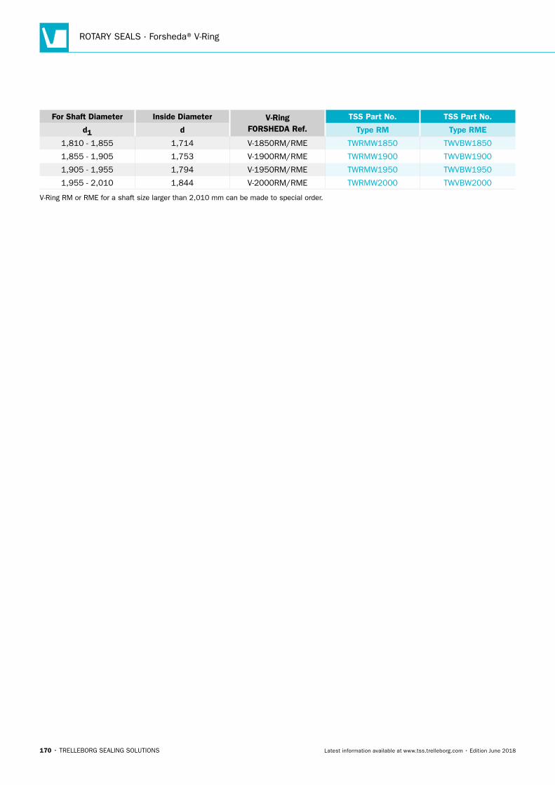
ROTARY SEALS · Forsheda® V-Ring
170 • TRELLEBORG SEALING SOLUTIONS Latest information available at www.tss.trelleborg.com • Edition June 2018
For Shaft Diameter Inside Diameter V-RingFORSHEDA Ref.
TSS Part No. TSS Part No.
d1 d Type RM Type RME
1,810 - 1,855 1,714 V-1850RM/RME TWRMW1850 TWVBW1850
1,855 - 1,905 1,753 V-1900RM/RME TWRMW1900 TWVBW1900
1,905 - 1,955 1,794 V-1950RM/RME TWRMW1950 TWVBW1950
1,955 - 2,010 1,844 V-2000RM/RME TWRMW2000 TWVBW2000
V-Ring RM or RME for a shaft size larger than 2,010 mm can be made to special order.
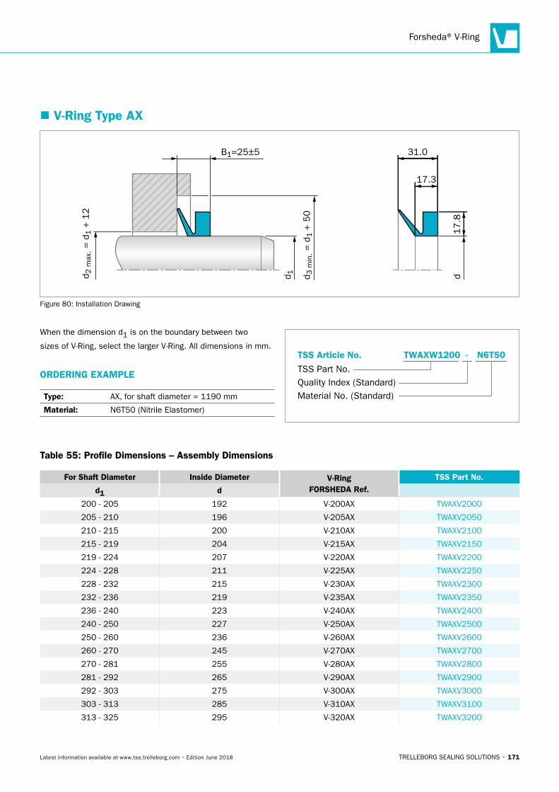
Forsheda® V-Ring
TRELLEBORG SEALING SOLUTIONS • 171Latest information available at www.tss.trelleborg.com • Edition June 2018
� V-Ring Type AX
d 1
31.0
d
17.3
17.8
B1=25±5
d 3 m
in. =
d1 +
50
d 2 m
ax. =
d1 +
12
Figure 80: Installation Drawing
When the dimension d1 is on the boundary between two
sizes of V-Ring, select the larger V-Ring. All dimensions in mm.
ORDERING EXAMPLE
Type: AX, for shaft diameter = 1190 mm
Material: N6T50 (Nitrile Elastomer)
Material No. (Standard)
TSS Part No.
TSS Article No. TWAXW1200 N6T50-
Quality Index (Standard)
Table 55: Profile Dimensions – Assembly Dimensions
For Shaft Diameter Inside Diameter V-RingFORSHEDA Ref.
TSS Part No.
d1 d
200 - 205 192 V-200AX TWAXV2000
205 - 210 196 V-205AX TWAXV2050
210 - 215 200 V-210AX TWAXV2100
215 - 219 204 V-215AX TWAXV2150
219 - 224 207 V-220AX TWAXV2200
224 - 228 211 V-225AX TWAXV2250
228 - 232 215 V-230AX TWAXV2300
232 - 236 219 V-235AX TWAXV2350
236 - 240 223 V-240AX TWAXV2400
240 - 250 227 V-250AX TWAXV2500
250 - 260 236 V-260AX TWAXV2600
260 - 270 245 V-270AX TWAXV2700
270 - 281 255 V-280AX TWAXV2800
281 - 292 265 V-290AX TWAXV2900
292 - 303 275 V-300AX TWAXV3000
303 - 313 285 V-310AX TWAXV3100
313 - 325 295 V-320AX TWAXV3200
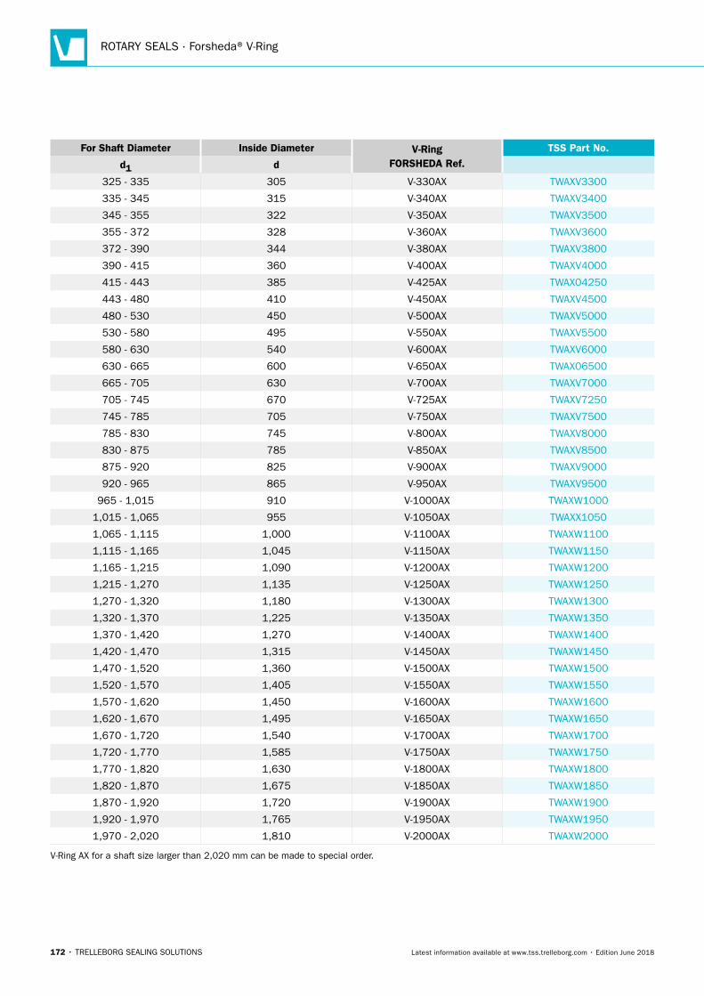
ROTARY SEALS · Forsheda® V-Ring
172 • TRELLEBORG SEALING SOLUTIONS Latest information available at www.tss.trelleborg.com • Edition June 2018
For Shaft Diameter Inside Diameter V-RingFORSHEDA Ref.
TSS Part No.
d1 d
325 - 335 305 V-330AX TWAXV3300
335 - 345 315 V-340AX TWAXV3400
345 - 355 322 V-350AX TWAXV3500
355 - 372 328 V-360AX TWAXV3600
372 - 390 344 V-380AX TWAXV3800
390 - 415 360 V-400AX TWAXV4000
415 - 443 385 V-425AX TWAX04250
443 - 480 410 V-450AX TWAXV4500
480 - 530 450 V-500AX TWAXV5000
530 - 580 495 V-550AX TWAXV5500
580 - 630 540 V-600AX TWAXV6000
630 - 665 600 V-650AX TWAX06500
665 - 705 630 V-700AX TWAXV7000
705 - 745 670 V-725AX TWAXV7250
745 - 785 705 V-750AX TWAXV7500
785 - 830 745 V-800AX TWAXV8000
830 - 875 785 V-850AX TWAXV8500
875 - 920 825 V-900AX TWAXV9000
920 - 965 865 V-950AX TWAXV9500
965 - 1,015 910 V-1000AX TWAXW1000
1,015 - 1,065 955 V-1050AX TWAXX1050
1,065 - 1,115 1,000 V-1100AX TWAXW1100
1,115 - 1,165 1,045 V-1150AX TWAXW1150
1,165 - 1,215 1,090 V-1200AX TWAXW1200
1,215 - 1,270 1,135 V-1250AX TWAXW1250
1,270 - 1,320 1,180 V-1300AX TWAXW1300
1,320 - 1,370 1,225 V-1350AX TWAXW1350
1,370 - 1,420 1,270 V-1400AX TWAXW1400
1,420 - 1,470 1,315 V-1450AX TWAXW1450
1,470 - 1,520 1,360 V-1500AX TWAXW1500
1,520 - 1,570 1,405 V-1550AX TWAXW1550
1,570 - 1,620 1,450 V-1600AX TWAXW1600
1,620 - 1,670 1,495 V-1650AX TWAXW1650
1,670 - 1,720 1,540 V-1700AX TWAXW1700
1,720 - 1,770 1,585 V-1750AX TWAXW1750
1,770 - 1,820 1,630 V-1800AX TWAXW1800
1,820 - 1,870 1,675 V-1850AX TWAXW1850
1,870 - 1,920 1,720 V-1900AX TWAXW1900
1,920 - 1,970 1,765 V-1950AX TWAXW1950
1,970 - 2,020 1,810 V-2000AX TWAXW2000
V-Ring AX for a shaft size larger than 2,020 mm can be made to special order.
TRELLEBORG SEALING SOLUTIONS • 173Latest information available at www.tss.trelleborg.com • Edition June 2018
GAMMA Seal

ROTARY SEALS · GAMMA Seal
174 • TRELLEBORG SEALING SOLUTIONS Latest information available at www.tss.trelleborg.com • Edition June 2018
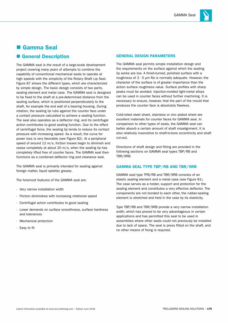
GAMMA Seal
TRELLEBORG SEALING SOLUTIONS • 175Latest information available at www.tss.trelleborg.com • Edition June 2018
� Gamma Seal � General Description
The GAMMA seal is the result of a large-scale development project covering many years of attempts to combine the capability of conventional mechanical seals to operate at high speeds with the simplicity of the Rotary Shaft Lip Seal. Figure 87 shows the different types, which are characterized by simple design. The basic design consists of two parts, sealing element and metal case. The GAMMA seal is designed to be fixed to the shaft at a pre-determined distance from the sealing surface, which is positioned perpendicularly to the shaft, for example the end wall of a bearing housing. During rotation, the sealing lip rubs against the counter face under a contact pressure calculated to achieve a sealing function. The seal also operates as a deflector ring, and its centrifugal action contributes to good sealing function. Due to the effect of centrifugal force, the sealing lip tends to reduce its contact pressure with increasing speed. As a result, the curve for power loss is very favorable (see Figure 82). At a peripheral speed of around 12 m/s, friction losses begin to diminish and cease completely at about 20 m/s, when the sealing lip has completely lifted free of counter faces. The GAMMA seal then functions as a combined deflector ring and clearance seal.
The GAMMA seal is primarily intended for sealing against foreign matter, liquid splatter, grease.
The foremost features of the GAMMA seal are:
- Very narrow installation width
- Friction diminishes with increasing rotational speed
- Centrifugal action contributes to good sealing
- Lower demands on surface smoothness, surface hardness and tolerances
- Mechanical protection
- Easy to fit
GENERAL DESIGN PARAMETERS
The GAMMA seal permits simple installation design and the requirements on the surface against which the sealing lip works are low. A finish-turned, polished surface with a roughness of 3 - 5 μm Ra is normally adequate. However, the character of the surface is of greater importance than the action surface roughness value. Surface profiles with sharp peaks must be avoided. Injection-molded light-metal alloys can be used in counter faces without further machining. It is necessary to ensure, however, that the part of the mould that produces the counter face is absolutely flawless.
Cold-rolled steel sheet, stainless or zinc plated sheet are excellent materials for counter faces for GAMMA seal. In comparison to other types of seals, the GAMMA seal can better absorb a certain amount of shaft misalignment. It is also relatively insensitive to shaft-to-bore eccentricity and shaft run-out.
Directions of shaft design and fitting are provided in the following sections on GAMMA seal types TBP/RB and TBR/9RB.
GAMMA SEAL TYPE TBP/RB AND TBR/9RB
GAMMA seal type TPB/RB and TBR/9RB consists of an elastic sealing element and a metal case (see Figure 81). The case serves as a holder, support and protection for the sealing element and constitutes a very effective deflector. The components are not bonded to each other, the rubber-sealing element is stretched and held in the case by its elasticity.
Type TBP/RB and TBR/9RB provide a very narrow installation width, which has proved to be very advantageous in certain applications and has permitted this seal to be used in assemblies where other seals could not previously be installed due to lack of space. The seal is press fitted on the shaft, and no other means of fixing is required.
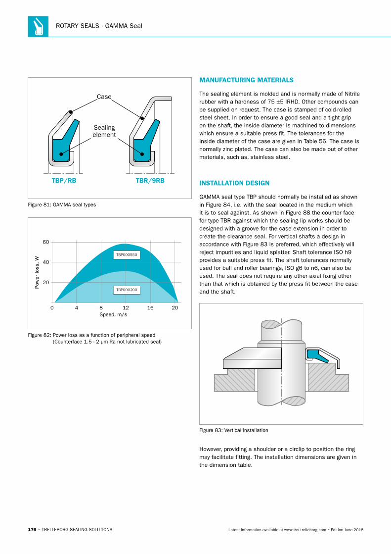
ROTARY SEALS · GAMMA Seal
176 • TRELLEBORG SEALING SOLUTIONS Latest information available at www.tss.trelleborg.com • Edition June 2018
Case
Sealing element
TBR/9RBTBP/RB
Figure 81: GAMMA seal types
0 4 8 12 16 20
20
40
60
Pow
er lo
ss, W
Speed, m/s
TBP000550
TBP000200
Figure 82: Power loss as a function of peripheral speed (Counterface 1.5 - 2 μm Ra not lubricated seal)
MANUFACTURING MATERIALS
The sealing element is molded and is normally made of Nitrile rubber with a hardness of 75 ±5 IRHD. Other compounds can be supplied on request. The case is stamped of cold-rolled steel sheet. In order to ensure a good seal and a tight grip on the shaft, the inside diameter is machined to dimensions which ensure a suitable press fit. The tolerances for the inside diameter of the case are given in Table 56. The case is normally zinc plated. The case can also be made out of other materials, such as, stainless steel.
INSTALLATION DESIGN
GAMMA seal type TBP should normally be installed as shown in Figure 84, i.e. with the seal located in the medium which it is to seal against. As shown in Figure 88 the counter face for type TBR against which the sealing lip works should be designed with a groove for the case extension in order to create the clearance seal. For vertical shafts a design in accordance with Figure 83 is preferred, which effectively will reject impurities and liquid splatter. Shaft tolerance ISO h9 provides a suitable press fit. The shaft tolerances normally used for ball and roller bearings, ISO g6 to n6, can also be used. The seal does not require any other axial fixing other than that which is obtained by the press fit between the case and the shaft.
Figure 83: Vertical installation
However, providing a shoulder or a circlip to position the ring may facilitate fitting. The installation dimensions are given in the dimension table.
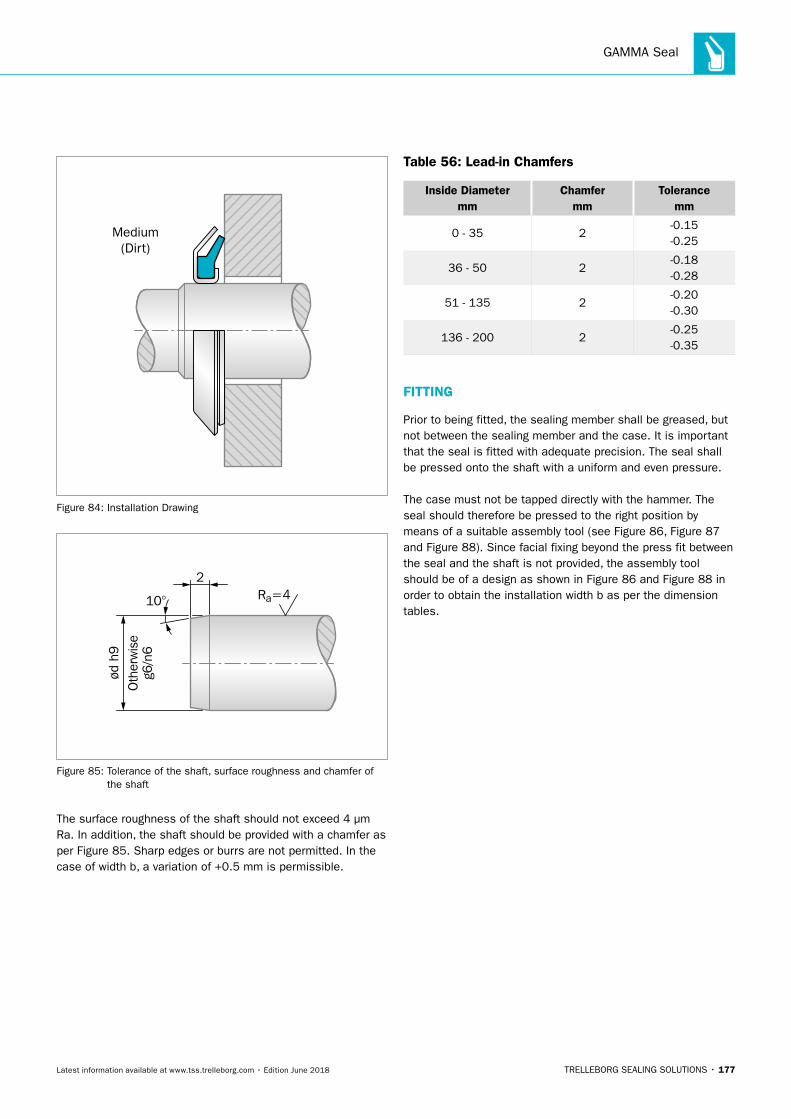
GAMMA Seal
TRELLEBORG SEALING SOLUTIONS • 177Latest information available at www.tss.trelleborg.com • Edition June 2018
Medium(Dirt)
Figure 84: Installation Drawing
ød h
9O
ther
wis
eg6
/n6
Ra=410°
2
Figure 85: Tolerance of the shaft, surface roughness and chamfer of the shaft
The surface roughness of the shaft should not exceed 4 μm Ra. In addition, the shaft should be provided with a chamfer as per Figure 85. Sharp edges or burrs are not permitted. In the case of width b, a variation of +0.5 mm is permissible.
Table 56: Lead-in Chamfers
Inside Diameter mm
Chamfer mm
Tolerance mm
0 - 35 2-0.15 -0.25
36 - 50 2-0.18 -0.28
51 - 135 2-0.20 -0.30
136 - 200 2-0.25 -0.35
FITTING
Prior to being fitted, the sealing member shall be greased, but not between the sealing member and the case. It is important that the seal is fitted with adequate precision. The seal shall be pressed onto the shaft with a uniform and even pressure.
The case must not be tapped directly with the hammer. The seal should therefore be pressed to the right position by means of a suitable assembly tool (see Figure 86, Figure 87 and Figure 88). Since facial fixing beyond the press fit between the seal and the shaft is not provided, the assembly tool should be of a design as shown in Figure 86 and Figure 88 in order to obtain the installation width b as per the dimension tables.
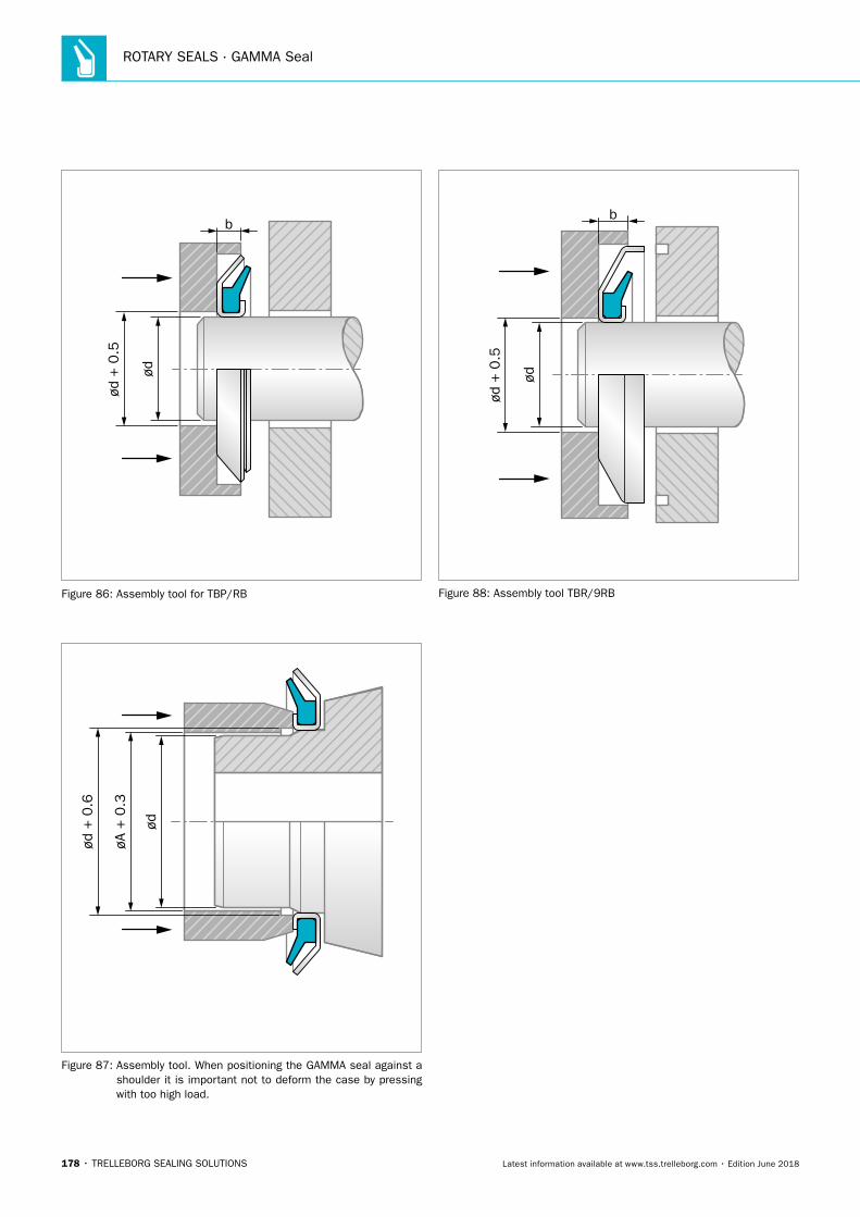
ROTARY SEALS · GAMMA Seal
178 • TRELLEBORG SEALING SOLUTIONS Latest information available at www.tss.trelleborg.com • Edition June 2018
ød
ød +
0.5
b
Figure 86: Assembly tool for TBP/RB
ød
øA +
0.3
ød +
0.6
Figure 87: Assembly tool. When positioning the GAMMA seal against a shoulder it is important not to deform the case by pressing with too high load.
ød
ød +
0.5
b
Figure 88: Assembly tool TBR/9RB
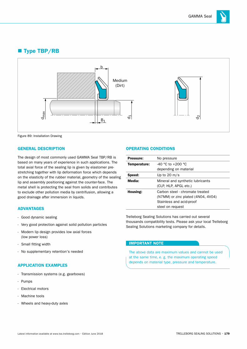
GAMMA Seal
TRELLEBORG SEALING SOLUTIONS • 179Latest information available at www.tss.trelleborg.com • Edition June 2018
� Type TBP/RB
Medium(Dirt)
d 1 d 2d max
b
B1
Figure 89: Installation Drawing
GENERAL DESCRIPTION
The design of most commonly used GAMMA Seal TBP/RB is based on many years of experience in such applications. The total axial force of the sealing lip is given by elastomer pre-stretching together with lip deformation force which depends on the elasticity of the rubber material, geometry of the sealing lip and assembly positioning against the counter-face. The metal shell is protecting the seal from solids and contributes to exclude other pollution media by centrifusion, allowing a good drainage after immersion in liquids.
ADVANTAGES
- Good dynamic sealing
- Very good protection against solid pollution particles
- Modern lip design provides low axial forces (lo w power loss)
- Small fitting width
- No supplementary retention's needed
APPLICATION EXAMPLES
- Transmission systems (e.g. gearboxes)
- Pumps
- Electrical motors
- Machine tools
- Wheels and heavy-duty axles
OPERATING CONDITIONS
Pressure: No pressure
Temperature: -40 °C to +200 °C depending on material
Speed: Up to 20 m/s
Media: Mineral and synthetic lubricants (CLP, HLP, APGL etc.)
Housing: Carbon steel - chromate treated(N7MM) or zinc plated (4N04, 4V04)Stainless and acid-proofsteel on request
Trelleborg Sealing Solutions has carried out several thousands compatibility tests. Please ask your local Trelleborg Sealing Solutions marketing company for details.
IMPORTANT NOTE
The above data are maximum values and cannot be used at the same time, e. g. the maximum operating speed depends on material type, pressure and temperature.
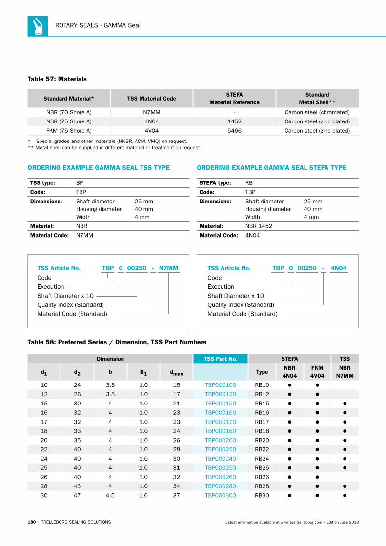
ROTARY SEALS · GAMMA Seal
180 • TRELLEBORG SEALING SOLUTIONS Latest information available at www.tss.trelleborg.com • Edition June 2018
Table 57: Materials
Standard Material* TSS Material CodeSTEFA
Material ReferenceStandard
Metal Shell**
NBR (70 Shore A) N7MM - Carbon steel (chromated)
NBR (75 Shore A) 4N04 1452 Carbon steel (zinc plated)
FKM (75 Shore A) 4V04 5466 Carbon steel (zinc plated)
* Special grades and other materials (HNBR, ACM, VMQ) on request. ** Metal shell can be supplied in different material or treatment on request.
Table 58: Preferred Series / Dimension, TSS Part Numbers
Dimension TSS Part No. STEFA TSS
d1 d2 b B1 dmax TypeNBR 4N04
FKM 4V04
NBR N7MM
10 24 3.5 1.0 15 TBP000100 RB10
12 26 3.5 1.0 17 TBP000120 RB12
15 30 4 1.0 21 TBP000150 RB15
16 32 4 1.0 23 TBP000160 RB16
17 32 4 1.0 23 TBP000170 RB17
18 33 4 1.0 24 TBP000180 RB18
20 35 4 1.0 26 TBP000200 RB20
22 40 4 1.0 28 TBP000220 RB22
24 40 4 1.0 30 TBP000240 RB24
25 40 4 1.0 31 TBP000250 RB25
26 40 4 1.0 32 TBP000260 RB26
28 43 4 1.0 34 TBP000280 RB28
30 47 4.5 1.0 37 TBP000300 RB30
ORDERING EXAMPLE GAMMA SEAL TSS TYPE
TSS type: BP
Code: TBP
Dimensions: Shaft diameter 25 mmHousing diameter 40 mmWidth 4 mm
Material: NBR
Material Code: N7MM
Material Code (Standard)
Code
TSS Article No. -
Shaft Diameter x 10Quality Index (Standard)
TBP
Execution
002500 N7MM
ORDERING EXAMPLE GAMMA SEAL STEFA TYPE
STEFA type: RB
Code: TBP
Dimensions: Shaft diameter 25 mmHousing diameter 40 mmWidth 4 mm
Material: NBR 1452
Material Code: 4N04
Material Code (Standard)
Code
TSS Article No. -
Shaft Diameter x 10Quality Index (Standard)
TBP
Execution
002500 4N04
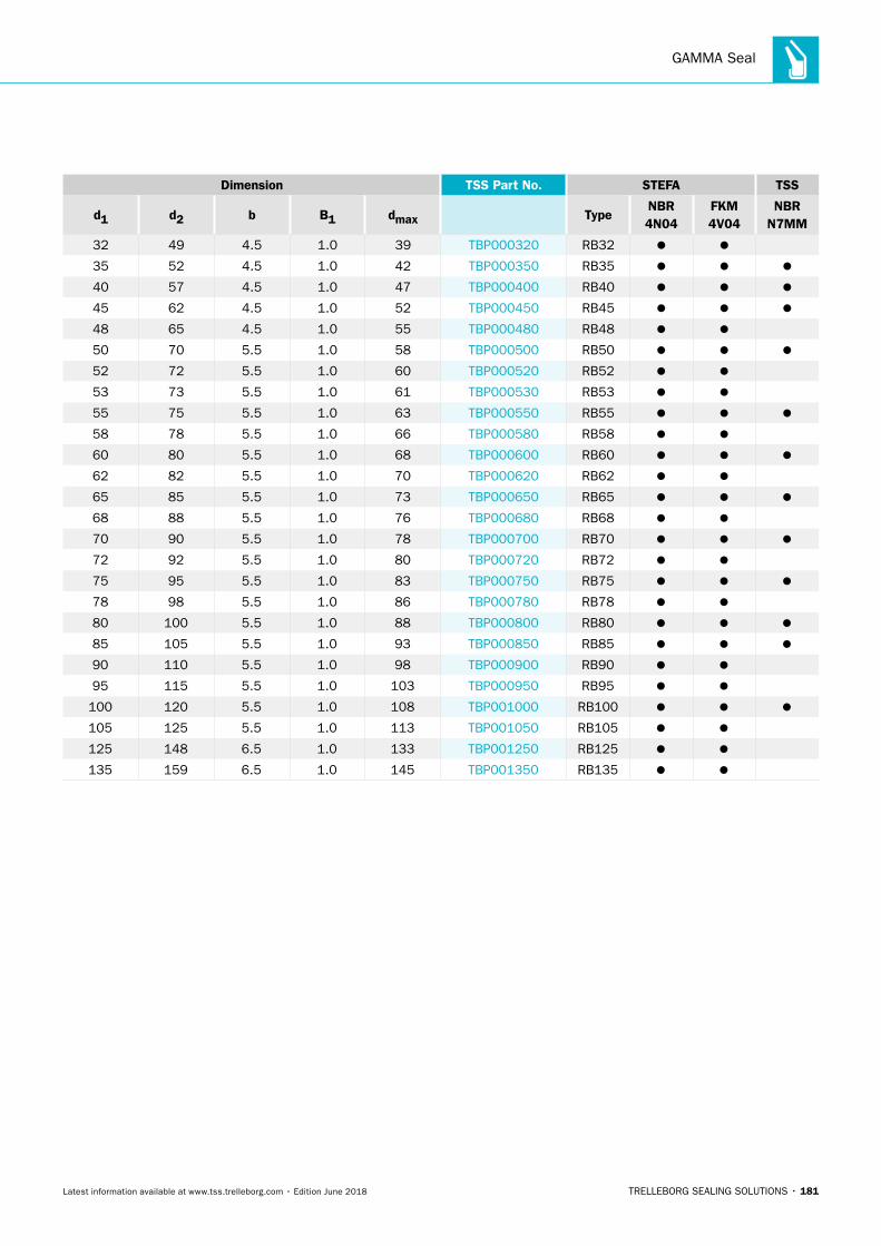
GAMMA Seal
TRELLEBORG SEALING SOLUTIONS • 181Latest information available at www.tss.trelleborg.com • Edition June 2018
Dimension TSS Part No. STEFA TSS
d1 d2 b B1 dmax TypeNBR 4N04
FKM 4V04
NBR N7MM
32 49 4.5 1.0 39 TBP000320 RB32
35 52 4.5 1.0 42 TBP000350 RB35
40 57 4.5 1.0 47 TBP000400 RB40
45 62 4.5 1.0 52 TBP000450 RB45
48 65 4.5 1.0 55 TBP000480 RB48
50 70 5.5 1.0 58 TBP000500 RB50
52 72 5.5 1.0 60 TBP000520 RB52
53 73 5.5 1.0 61 TBP000530 RB53
55 75 5.5 1.0 63 TBP000550 RB55
58 78 5.5 1.0 66 TBP000580 RB58
60 80 5.5 1.0 68 TBP000600 RB60
62 82 5.5 1.0 70 TBP000620 RB62
65 85 5.5 1.0 73 TBP000650 RB65
68 88 5.5 1.0 76 TBP000680 RB68
70 90 5.5 1.0 78 TBP000700 RB70
72 92 5.5 1.0 80 TBP000720 RB72
75 95 5.5 1.0 83 TBP000750 RB75
78 98 5.5 1.0 86 TBP000780 RB78
80 100 5.5 1.0 88 TBP000800 RB80
85 105 5.5 1.0 93 TBP000850 RB85
90 110 5.5 1.0 98 TBP000900 RB90
95 115 5.5 1.0 103 TBP000950 RB95
100 120 5.5 1.0 108 TBP001000 RB100
105 125 5.5 1.0 113 TBP001050 RB105
125 148 6.5 1.0 133 TBP001250 RB125
135 159 6.5 1.0 145 TBP001350 RB135
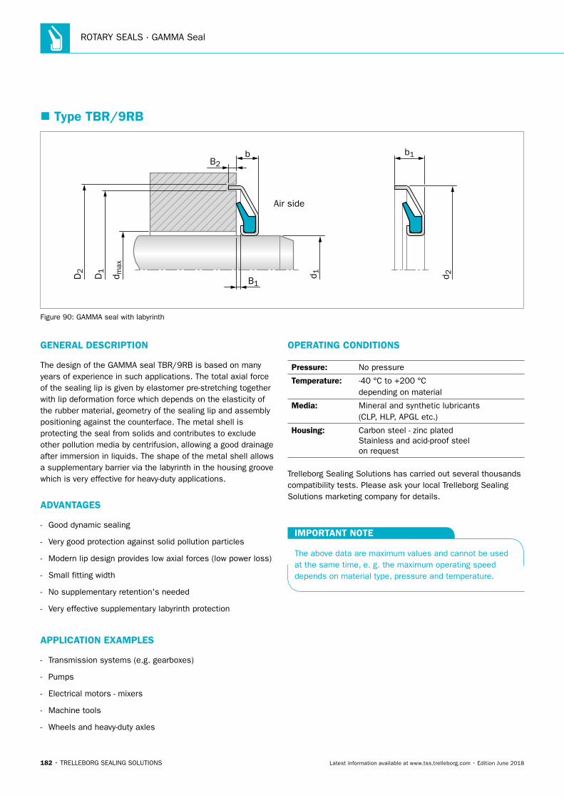
ROTARY SEALS · GAMMA Seal
182 • TRELLEBORG SEALING SOLUTIONS Latest information available at www.tss.trelleborg.com • Edition June 2018
� Type TBR/9RB
B2
d 1 d 2d max
D1
D2
b
B1
Air side
b1
Figure 90: GAMMA seal with labyrinth
GENERAL DESCRIPTION
The design of the GAMMA seal TBR/9RB is based on many years of experience in such applications. The total axial force of the sealing lip is given by elastomer pre-stretching together with lip deformation force which depends on the elasticity of the rubber material, geometry of the sealing lip and assembly positioning against the counterface. The metal shell is protecting the seal from solids and contributes to exclude other pollution media by centrifusion, allowing a good drainage after immersion in liquids. The shape of the metal shell allows a supplementary barrier via the labyrinth in the housing groove which is very effective for heavy-duty applications.
ADVANTAGES
- Good dynamic sealing
- Very good protection against solid pollution particles
- Modern lip design provides low axial forces (low power loss)
- Small fitting width
- No supplementary retention's needed
- Very effective supplementary labyrinth protection
APPLICATION EXAMPLES
- Transmission systems (e.g. gearboxes)
- Pumps
- Electrical motors - mixers
- Machine tools
- Wheels and heavy-duty axles
OPERATING CONDITIONS
Pressure: No pressure
Temperature: -40 °C to +200 °C depending on material
Media: Mineral and synthetic lubricants (CLP, HLP, APGL etc.)
Housing: Carbon steel - zinc platedStainless and acid-proof steel on request
Trelleborg Sealing Solutions has carried out several thousands compatibility tests. Please ask your local Trelleborg Sealing Solutions marketing company for details.
IMPORTANT NOTE
The above data are maximum values and cannot be used at the same time, e. g. the maximum operating speed depends on material type, pressure and temperature.
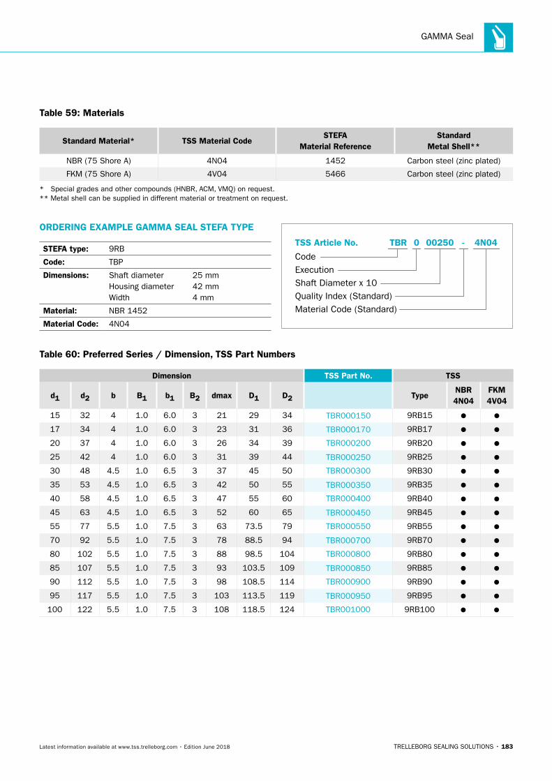
GAMMA Seal
TRELLEBORG SEALING SOLUTIONS • 183Latest information available at www.tss.trelleborg.com • Edition June 2018
Table 59: Materials
Standard Material* TSS Material CodeSTEFA
Material ReferenceStandard
Metal Shell**
NBR (75 Shore A) 4N04 1452 Carbon steel (zinc plated)
FKM (75 Shore A) 4V04 5466 Carbon steel (zinc plated)
* Special grades and other compounds (HNBR, ACM, VMQ) on request. ** Metal shell can be supplied in different material or treatment on request.
ORDERING EXAMPLE GAMMA SEAL STEFA TYPE
STEFA type: 9RB
Code: TBP
Dimensions: Shaft diameter 25 mmHousing diameter 42 mmWidth 4 mm
Material: NBR 1452
Material Code: 4N04
Material Code (Standard)
Code
TSS Article No. -
Shaft Diameter x 10Quality Index (Standard)
TBR
Execution
002500 4N04
Table 60: Preferred Series / Dimension, TSS Part Numbers
Dimension TSS Part No. TSS
d1 d2 b B1 b1 B2 dmax D1 D2 TypeNBR 4N04
FKM 4V04
15 32 4 1.0 6.0 3 21 29 34 TBR000150 9RB15
17 34 4 1.0 6.0 3 23 31 36 TBR000170 9RB17
20 37 4 1.0 6.0 3 26 34 39 TBR000200 9RB20
25 42 4 1.0 6.0 3 31 39 44 TBR000250 9RB25
30 48 4.5 1.0 6.5 3 37 45 50 TBR000300 9RB30
35 53 4.5 1.0 6.5 3 42 50 55 TBR000350 9RB35
40 58 4.5 1.0 6.5 3 47 55 60 TBR000400 9RB40
45 63 4.5 1.0 6.5 3 52 60 65 TBR000450 9RB45
55 77 5.5 1.0 7.5 3 63 73.5 79 TBR000550 9RB55
70 92 5.5 1.0 7.5 3 78 88.5 94 TBR000700 9RB70
80 102 5.5 1.0 7.5 3 88 98.5 104 TBR000800 9RB80
85 107 5.5 1.0 7.5 3 93 103.5 109 TBR000850 9RB85
90 112 5.5 1.0 7.5 3 98 108.5 114 TBR000900 9RB90
95 117 5.5 1.0 7.5 3 103 113.5 119 TBR000950 9RB95
100 122 5.5 1.0 7.5 3 108 118.5 124 TBR001000 9RB100

ROTARY SEALS · GAMMA Seal
184 • TRELLEBORG SEALING SOLUTIONS Latest information available at www.tss.trelleborg.com • Edition June 2018
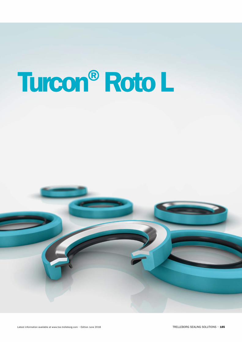
TRELLEBORG SEALING SOLUTIONS • 185Latest information available at www.tss.trelleborg.com • Edition June 2018
Turcon®Roto L

ROTARY SEALS · Turcon®Roto L
186 • TRELLEBORG SEALING SOLUTIONS Latest information available at www.tss.trelleborg.com • Edition June 2018
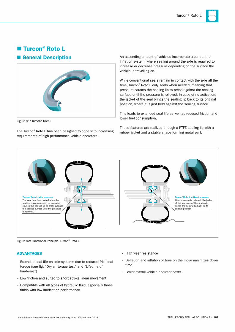
Turcon®Roto L
TRELLEBORG SEALING SOLUTIONS • 187Latest information available at www.tss.trelleborg.com • Edition June 2018
The seal is only activated when thesystem is pressurized. The pressure causes the sealing lip to press againstthe sealing surface until the pressureis relieved.
After pressure is relieved. the jacket of the seal, acting like a spring, brings the sealing lip back to its original position.
Turcon® Roto L without pressureTurcon® Roto L with pressure
Figure 92: Functional Principle Turcon®Roto L
� General Description
Figure 91: Turcon®Roto L
The Turcon®Roto L has been designed to cope with increasing requirements of high performance vehicle operators.
An ascending amount of vehicles incorporate a central tire inflation system, where sealing around the axle is required to increase or decrease pressure depending on the surface the vehicle is travelling on.
While conventional seals remain in contact with the axle all the time, Turcon®Roto L only seals when needed, meaning that pressure causes the sealing lip to press against the sealing surface until the pressure is relieved. In case of no activation, the jacket of the seal brings the sealing lip back to its original position, where it is just held against the sealing surface.
This leads to extended seal life as well as reduced friction and lower fuel consumption.
These features are realized through a PTFE sealing lip with a rubber jacket and a stable shape forming metal part.
� Turcon®Roto L
ADVANTAGES
- Extended seal life on axle systems due to reduced frictional torque (see fig. “Dry air torque test” and “Lifetime of hardware”)
- Low friction and suited to short stroke linear movement
- Compatible with all types of hydraulic fluid, especially those fluids with low lubrication performance
- High wear resistance
- Deflation and inflation of tires on the move minimizes down time
- Lower overall vehicle operator costs
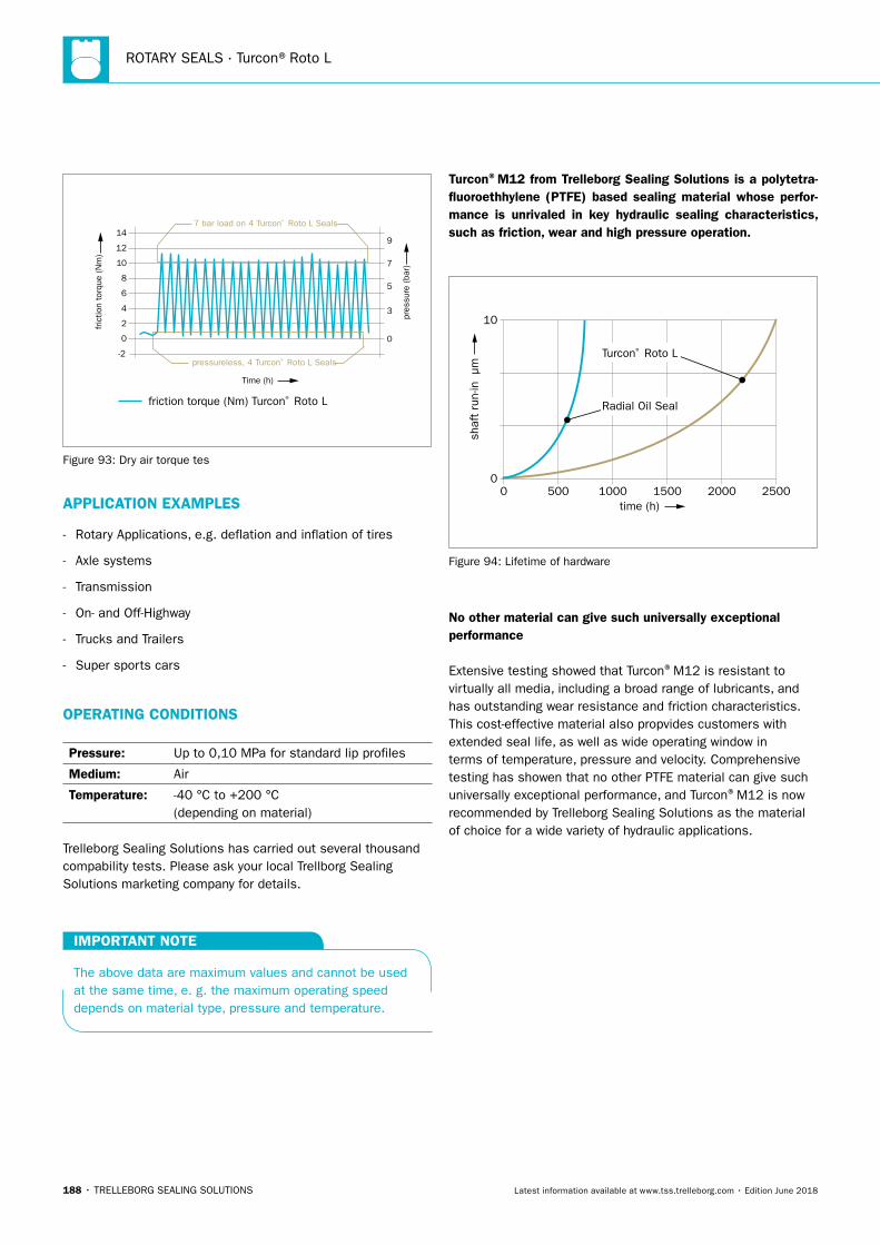
ROTARY SEALS · Turcon®Roto L
188 • TRELLEBORG SEALING SOLUTIONS Latest information available at www.tss.trelleborg.com • Edition June 2018
-2
0
2
4
6
8
10
12
14
fric
tion
torq
ue (N
m)
Time (h)
friction torque (Nm) Turcon® Roto L
7 bar load on 4 Turcon® Roto L Seals
pressureless, 4 Turcon® Roto L Seals
0
3
5
7
9
pres
sure
(ba
r)
Figure 93: Dry air torque tes
APPLICATION EXAMPLES
- Rotary Applications, e.g. deflation and inflation of tires
- Axle systems
- Transmission
- On- and Off-Highway
- Trucks and Trailers
- Super sports cars
OPERATING CONDITIONS
Pressure: Up to 0,10 MPa for standard lip profiles
Medium: Air
Temperature: -40 °C to +200 °C (depending on material)
Trelleborg Sealing Solutions has carried out several thousand compability tests. Please ask your local Trellborg Sealing Solutions marketing company for details.
IMPORTANT NOTE
The above data are maximum values and cannot be used at the same time, e. g. the maximum operating speed depends on material type, pressure and temperature.
Turcon®M12 from Trelleborg Sealing Solutions is a polytetra-fluoroethhylene (PTFE) based sealing material whose perfor-mance is unrivaled in key hydraulic sealing characteristics, such as friction, wear and high pressure operation.
time (h)0
0
10
500 1000
shaf
t ru
n-in
µm
1500 2000 2500
Radial Oil Seal
Turcon® Roto L
Figure 94: Lifetime of hardware
No other material can give such universally exceptional performance
Extensive testing showed that Turcon®M12 is resistant to virtually all media, including a broad range of lubricants, and has outstanding wear resistance and friction characteristics. This cost-effective material also propvides customers with extended seal life, as well as wide operating window in terms of temperature, pressure and velocity. Comprehensive testing has showen that no other PTFE material can give such universally exceptional performance, and Turcon®M12 is now recommended by Trelleborg Sealing Solutions as the material of choice for a wide variety of hydraulic applications.
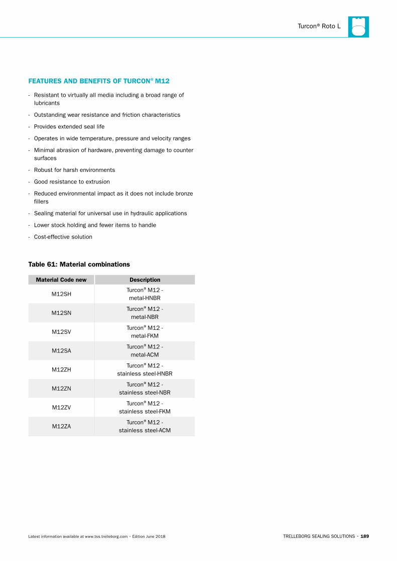
Turcon®Roto L
TRELLEBORG SEALING SOLUTIONS • 189Latest information available at www.tss.trelleborg.com • Edition June 2018
FEATURES AND BENEFITS OF TURCON®M12
- Resistant to virtually all media including a broad range of lubricants
- Outstanding wear resistance and friction characteristics
- Provides extended seal life
- Operates in wide temperature, pressure and velocity ranges
- Minimal abrasion of hardware, preventing damage to counter surfaces
- Robust for harsh environments
- Good resistance to extrusion
- Reduced environmental impact as it does not include bronze fillers
- Sealing material for universal use in hydraulic applications
- Lower stock holding and fewer items to handle
- Cost-effective solution
Table 61: Material combinations
Material Code new Description
M12SHTurcon®M12 -metal-HNBR
M12SNTurcon®M12 -
metal-NBR
M12SVTurcon®M12 -
metal-FKM
M12SATurcon®M12 -
metal-ACM
M12ZHTurcon®M12 -
stainless steel-HNBR
M12ZNTurcon®M12 -
stainless steel-NBR
M12ZVTurcon®M12 -
stainless steel-FKM
M12ZATurcon®M12 -
stainless steel-ACM

ROTARY SEALS · Turcon®Roto L
190 • TRELLEBORG SEALING SOLUTIONS Latest information available at www.tss.trelleborg.com • Edition June 2018
TRELLEBORG SEALING SOLUTIONS • 191Latest information available at www.tss.trelleborg.com • Edition June 2018
Turcon®Varilip®PDR

ROTARY SEALS · Turcon®Varilip®PDR
192 • TRELLEBORG SEALING SOLUTIONS Latest information available at www.tss.trelleborg.com • Edition June 2018
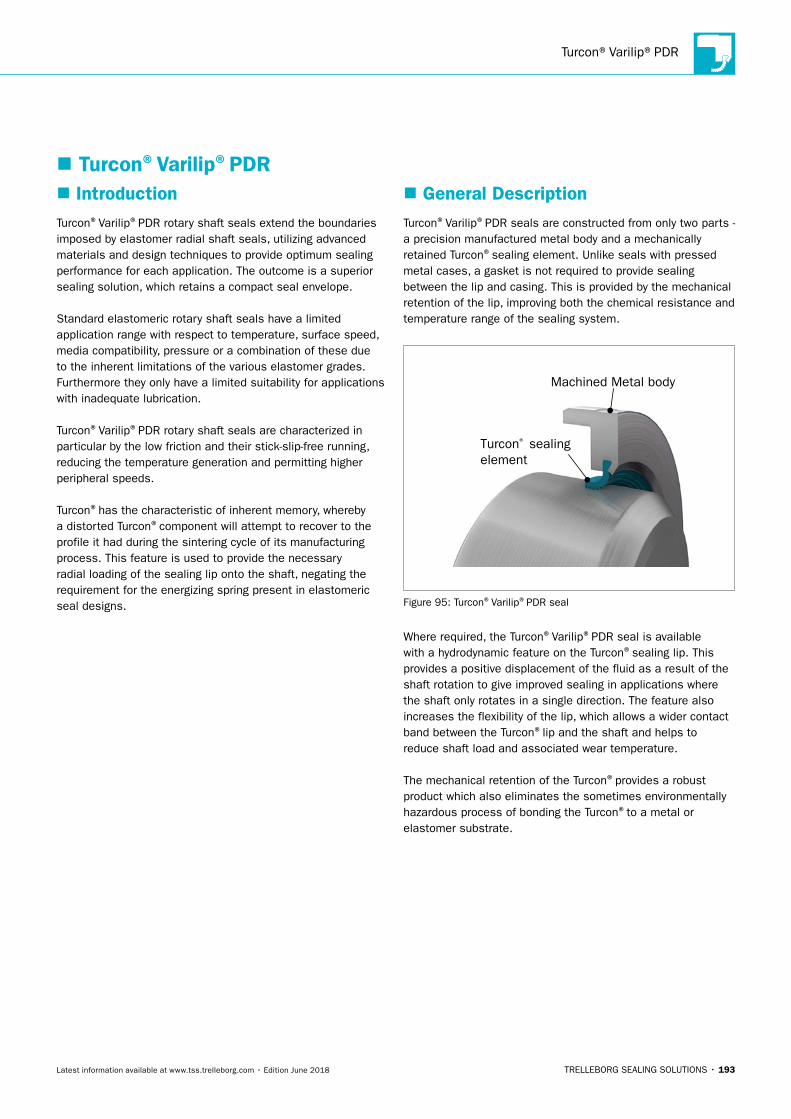
Turcon®Varilip®PDR
TRELLEBORG SEALING SOLUTIONS • 193Latest information available at www.tss.trelleborg.com • Edition June 2018
� IntroductionTurcon®Varilip®PDR rotary shaft seals extend the boundaries imposed by elastomer radial shaft seals, utilizing advanced materials and design techniques to provide optimum sealing performance for each application. The outcome is a superior sealing solution, which retains a compact seal envelope.
Standard elastomeric rotary shaft seals have a limited application range with respect to temperature, surface speed, media compatibility, pressure or a combination of these due to the inherent limitations of the various elastomer grades. Furthermore they only have a limited suitability for applications with inadequate lubrication.
Turcon®Varilip®PDR rotary shaft seals are characterized in particular by the low friction and their stick-slip-free running, reducing the temperature generation and permitting higher peripheral speeds.
Turcon®has the characteristic of inherent memory, whereby a distorted Turcon®component will attempt to recover to the profile it had during the sintering cycle of its manufacturing process. This feature is used to provide the necessary radial loading of the sealing lip onto the shaft, negating the requirement for the energizing spring present in elastomeric seal designs.
� General DescriptionTurcon®Varilip®PDR seals are constructed from only two parts - a precision manufactured metal body and a mechanically retained Turcon®sealing element. Unlike seals with pressed metal cases, a gasket is not required to provide sealing between the lip and casing. This is provided by the mechanical retention of the lip, improving both the chemical resistance and temperature range of the sealing system.
Machined Metal body
Turcon® sealingelement
Figure 95: Turcon®Varilip®PDR seal
Where required, the Turcon®Varilip®PDR seal is available with a hydrodynamic feature on the Turcon®sealing lip. This provides a positive displacement of the fluid as a result of the shaft rotation to give improved sealing in applications where the shaft only rotates in a single direction. The feature also increases the flexibility of the lip, which allows a wider contact band between the Turcon®lip and the shaft and helps to reduce shaft load and associated wear temperature.
The mechanical retention of the Turcon®provides a robust product which also eliminates the sometimes environmentally hazardous process of bonding the Turcon®to a metal or elastomer substrate.
� Turcon®Varilip®PDR
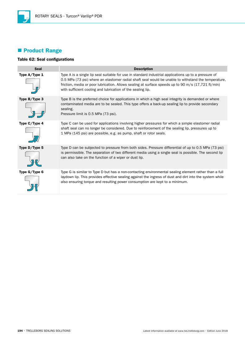
ROTARY SEALS · Turcon®Varilip®PDR
194 • TRELLEBORG SEALING SOLUTIONS Latest information available at www.tss.trelleborg.com • Edition June 2018
Table 62: Seal configurations
Seal Description
Type A/Type 1
Type A / Type 1
Type B / Type 3
Type C / Type 4
Type D / Type 5
Type G / Type 6
SealMax. Shaft
SpeedMax.
Pressurem/s ft/min
60 11,811 0.5 73
40 7,874 0.5 73
20 3,937 1.0 145
40 7,874 0.5 73
60 11,811 0.5 73
This is a single lip seal suitable for use in standard industrial applica-tions where an elastomer radial shaft seal would not be able to withstand the temperature, friction, media or poor lubrication condi-tions.
The preferred choice for applications in which high seal integrity is demanded or where contaminated media are to be sealed. This type offers a back-up sealing lip to provide secondary sealing.
Note: Secondary sealing element material is Turcon® M83 in standard seal configuration.
For use in applications involving higher pressures for which a simple elastomer radial shaft seal can no longer be considered. Due to reinforcement of the sealing lip, pressures up to 1 MPa (145 psi) are possible, e.g. as pump, shaft or rotor seals.
Note: Secondary support element material is M83 (not modifiable). Turcon® M83 is the recommended primary lip material.
For use in applications where the seal is subjected to pressure from both sides and/or applications where the seperation of two different media using a single seal is required.
Note: Secondary sealing element material is Turcon® M83 in standard seal configuration.
Similar configuration to Type D / Type 5 but has a non-contacting environmental sealing element rather than a full lay-down lip. This provides effective sealing against the ingress of external contami-nants into the system whilst also ensuring torque and resulting power consumption are kept to a minimum.
Note: Secondary dust/dirt element material is Turcon® T01 in standard seal configuration (not modifiable).
DescriptionMPa psiType A is a single lip seal suitable for use in standard industrial applications up to a pressure of
0.5 MPa (73 psi) where an elastomer radial shaft seal would be unable to withstand the temperature, friction, media or poor lubrication. Allows sealing at surface speeds up to 90 m/s (17,721 ft/min) with sufficient cooling and lubrication of the sealing lip.
Type B/Type 3Type A / Type 1
Type B / Type 3
Type C / Type 4
Type D / Type 5
Type G / Type 6
SealMax. Shaft
SpeedMax.
Pressurem/s ft/min
60 11,811 0.5 73
40 7,874 0.5 73
20 3,937 1.0 145
40 7,874 0.5 73
60 11,811 0.5 73
This is a single lip seal suitable for use in standard industrial applica-tions where an elastomer radial shaft seal would not be able to withstand the temperature, friction, media or poor lubrication condi-tions.
The preferred choice for applications in which high seal integrity is demanded or where contaminated media are to be sealed. This type offers a back-up sealing lip to provide secondary sealing.
Note: Secondary sealing element material is Turcon® M83 in standard seal configuration.
For use in applications involving higher pressures for which a simple elastomer radial shaft seal can no longer be considered. Due to reinforcement of the sealing lip, pressures up to 1 MPa (145 psi) are possible, e.g. as pump, shaft or rotor seals.
Note: Secondary support element material is M83 (not modifiable). Turcon® M83 is the recommended primary lip material.
For use in applications where the seal is subjected to pressure from both sides and/or applications where the seperation of two different media using a single seal is required.
Note: Secondary sealing element material is Turcon® M83 in standard seal configuration.
Similar configuration to Type D / Type 5 but has a non-contacting environmental sealing element rather than a full lay-down lip. This provides effective sealing against the ingress of external contami-nants into the system whilst also ensuring torque and resulting power consumption are kept to a minimum.
Note: Secondary dust/dirt element material is Turcon® T01 in standard seal configuration (not modifiable).
DescriptionMPa psi
Type B is the preferred choice for applications in which a high seal integrity is demanded or where contaminated media are to be sealed. This type offers a back-up sealing lip to provide secondary sealing. Pressure limit is 0.5 MPa (73 psi).
Type C/Type 4
Type A / Type 1
Type B / Type 3
Type C / Type 4
Type D / Type 5
Type G / Type 6
SealMax. Shaft
SpeedMax.
Pressurem/s ft/min
60 11,811 0.5 73
40 7,874 0.5 73
20 3,937 1.0 145
40 7,874 0.5 73
60 11,811 0.5 73
This is a single lip seal suitable for use in standard industrial applica-tions where an elastomer radial shaft seal would not be able to withstand the temperature, friction, media or poor lubrication condi-tions.
The preferred choice for applications in which high seal integrity is demanded or where contaminated media are to be sealed. This type offers a back-up sealing lip to provide secondary sealing.
Note: Secondary sealing element material is Turcon® M83 in standard seal configuration.
For use in applications involving higher pressures for which a simple elastomer radial shaft seal can no longer be considered. Due to reinforcement of the sealing lip, pressures up to 1 MPa (145 psi) are possible, e.g. as pump, shaft or rotor seals.
Note: Secondary support element material is M83 (not modifiable). Turcon® M83 is the recommended primary lip material.
For use in applications where the seal is subjected to pressure from both sides and/or applications where the seperation of two different media using a single seal is required.
Note: Secondary sealing element material is Turcon® M83 in standard seal configuration.
Similar configuration to Type D / Type 5 but has a non-contacting environmental sealing element rather than a full lay-down lip. This provides effective sealing against the ingress of external contami-nants into the system whilst also ensuring torque and resulting power consumption are kept to a minimum.
Note: Secondary dust/dirt element material is Turcon® T01 in standard seal configuration (not modifiable).
DescriptionMPa psi
Type C can be used for applications involving higher pressures for which a simple elastomer radial shaft seal can no longer be considered. Due to reinforcement of the sealing lip, pressures up to 1 MPa (145 psi) are possible, e.g. as pump, shaft or rotor seals.
Type D/Type 5
Type A / Type 1
Type B / Type 3
Type C / Type 4
Type D / Type 5
Type G / Type 6
SealMax. Shaft
SpeedMax.
Pressurem/s ft/min
60 11,811 0.5 73
40 7,874 0.5 73
20 3,937 1.0 145
40 7,874 0.5 73
60 11,811 0.5 73
This is a single lip seal suitable for use in standard industrial applica-tions where an elastomer radial shaft seal would not be able to withstand the temperature, friction, media or poor lubrication condi-tions.
The preferred choice for applications in which high seal integrity is demanded or where contaminated media are to be sealed. This type offers a back-up sealing lip to provide secondary sealing.
Note: Secondary sealing element material is Turcon® M83 in standard seal configuration.
For use in applications involving higher pressures for which a simple elastomer radial shaft seal can no longer be considered. Due to reinforcement of the sealing lip, pressures up to 1 MPa (145 psi) are possible, e.g. as pump, shaft or rotor seals.
Note: Secondary support element material is M83 (not modifiable). Turcon® M83 is the recommended primary lip material.
For use in applications where the seal is subjected to pressure from both sides and/or applications where the seperation of two different media using a single seal is required.
Note: Secondary sealing element material is Turcon® M83 in standard seal configuration.
Similar configuration to Type D / Type 5 but has a non-contacting environmental sealing element rather than a full lay-down lip. This provides effective sealing against the ingress of external contami-nants into the system whilst also ensuring torque and resulting power consumption are kept to a minimum.
Note: Secondary dust/dirt element material is Turcon® T01 in standard seal configuration (not modifiable).
DescriptionMPa psi
Type D can be subjected to pressure from both sides. Pressure differential of up to 0.5 MPa (73 psi) is permissible. The separation of two different media using a single seal is possible. The second lip can also take on the function of a wiper or dust lip.
Type G/Type 6
Type A / Type 1
Type B / Type 3
Type C / Type 4
Type D / Type 5
Type G / Type 6
SealMax. Shaft
SpeedMax.
Pressurem/s ft/min
60 11,811 0.5 73
40 7,874 0.5 73
20 3,937 1.0 145
40 7,874 0.5 73
60 11,811 0.5 73
This is a single lip seal suitable for use in standard industrial applica-tions where an elastomer radial shaft seal would not be able to withstand the temperature, friction, media or poor lubrication condi-tions.
The preferred choice for applications in which high seal integrity is demanded or where contaminated media are to be sealed. This type offers a back-up sealing lip to provide secondary sealing.
Note: Secondary sealing element material is Turcon® M83 in standard seal configuration.
For use in applications involving higher pressures for which a simple elastomer radial shaft seal can no longer be considered. Due to reinforcement of the sealing lip, pressures up to 1 MPa (145 psi) are possible, e.g. as pump, shaft or rotor seals.
Note: Secondary support element material is M83 (not modifiable). Turcon® M83 is the recommended primary lip material.
For use in applications where the seal is subjected to pressure from both sides and/or applications where the seperation of two different media using a single seal is required.
Note: Secondary sealing element material is Turcon® M83 in standard seal configuration.
Similar configuration to Type D / Type 5 but has a non-contacting environmental sealing element rather than a full lay-down lip. This provides effective sealing against the ingress of external contami-nants into the system whilst also ensuring torque and resulting power consumption are kept to a minimum.
Note: Secondary dust/dirt element material is Turcon® T01 in standard seal configuration (not modifiable).
DescriptionMPa psi
Type G is similar to Type D but has a non-contacting environmental sealing element rather than a full laydown lip. This provides effective sealing against the ingress of dust and dirt into the system while also ensuring torque and resulting power consumption are kept to a minimum.
� Product Range
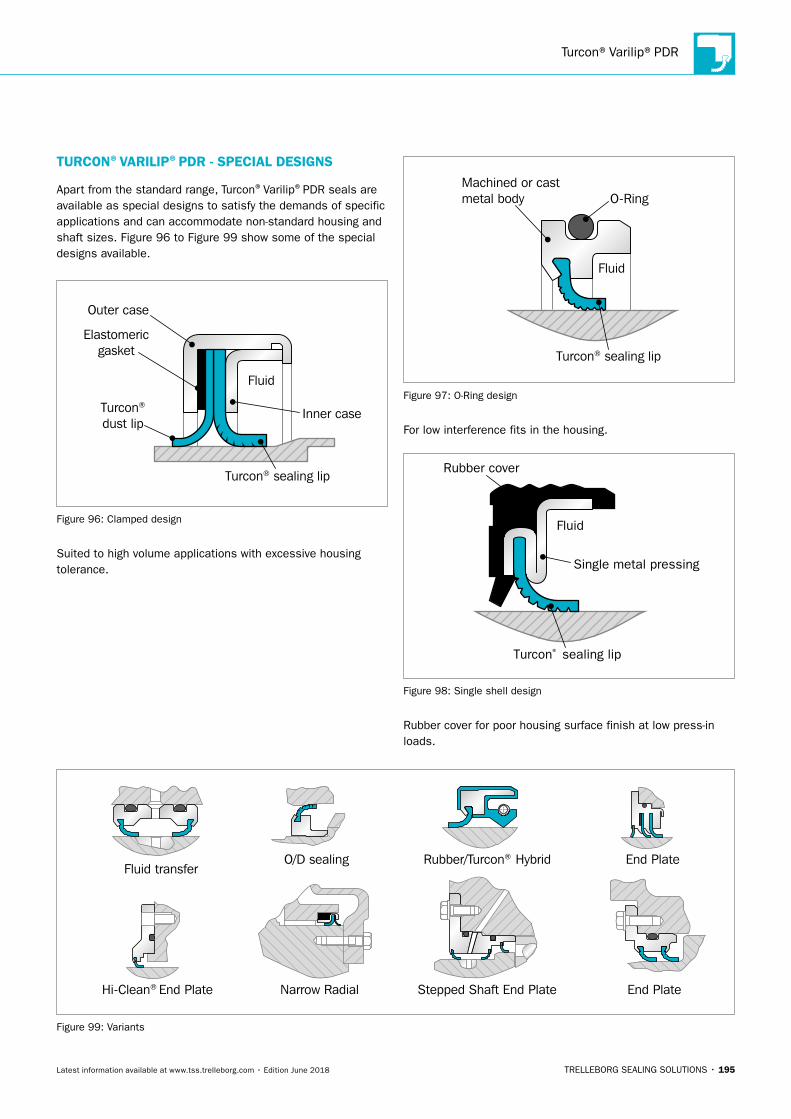
Turcon®Varilip®PDR
TRELLEBORG SEALING SOLUTIONS • 195Latest information available at www.tss.trelleborg.com • Edition June 2018
Stepped Shaft End PlateNarrow RadialHi-Clean® End Plate
Rubber/Turcon® HybridFluid transfer
O/D sealing End Plate
End Plate
Figure 99: Variants
TURCON®VARILIP®PDR - SPECIAL DESIGNS
Apart from the standard range, Turcon®Varilip®PDR seals are available as special designs to satisfy the demands of specific applications and can accommodate non-standard housing and shaft sizes. Figure 96 to Figure 99 show some of the special designs available.
Inner case
Outer case
Elastomericgasket
Fluid
Turcon® sealing lip
Turcon®
dust lip
Figure 96: Clamped design
Suited to high volume applications with excessive housing tolerance.
Fluid
Machined or cast metal body O-Ring
Turcon® sealing lip
Figure 97: O-Ring design
For low interference fits in the housing.
Fluid
Single metal pressing
Rubber cover
Turcon® sealing lip
Figure 98: Single shell design
Rubber cover for poor housing surface finish at low press-in loads.
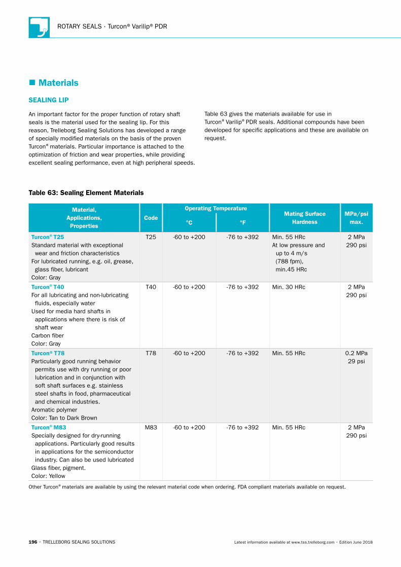
ROTARY SEALS · Turcon®Varilip®PDR
196 • TRELLEBORG SEALING SOLUTIONS Latest information available at www.tss.trelleborg.com • Edition June 2018
� Materials
SEALING LIP
An important factor for the proper function of rotary shaft seals is the material used for the sealing lip. For this reason, Trelleborg Sealing Solutions has developed a range of specially modified materials on the basis of the proven Turcon®materials. Particular importance is attached to the optimization of friction and wear properties, while providing excellent sealing performance, even at high peripheral speeds.
Table 63 gives the materials available for use in Turcon®Varilip®PDR seals. Additional compounds have been developed for specific applications and these are available on request.
Table 63: Sealing Element Materials
Material, Applications, Properties
Code
Operating TemperatureMating Surface
HardnessMPa/psi
max.°C °F
Turcon®T25Standard material with exceptional wear and friction characteristicsFor lubricated running, e.g. oil, grease, glass fiber, lubricantColor: Gray
T25 -60 to +200 -76 to +392 Min. 55 HRcAt low pressure and up to 4 m/s (788 fpm), min.45 HRc
2 MPa290 psi
Turcon®T40For all lubricating and non-lubricating fluids, especially waterUsed for media hard shafts in applications where there is risk of shaft wearCarbon fiberColor: Gray
T40 -60 to +200 -76 to +392 Min. 30 HRc 2 MPa290 psi
Turcon®T78Particularly good running behavior permits use with dry running or poor lubrication and in conjunction with soft shaft surfaces e.g. stainless steel shafts in food, pharmaceutical and chemical industries.Aromatic polymerColor: Tan to Dark Brown
T78 -60 to +200 -76 to +392 Min. 55 HRc 0.2 MPa29 psi
Turcon®M83Specially designed for dry-running applications. Particularly good results in applications for the semiconductor industry. Can also be used lubricatedGlass fiber, pigment.Color: Yellow
M83 -60 to +200 -76 to +392 Min. 55 HRc 2 MPa290 psi
Other Turcon®materials are available by using the relevant material code when ordering. FDA compliant materials available on request.
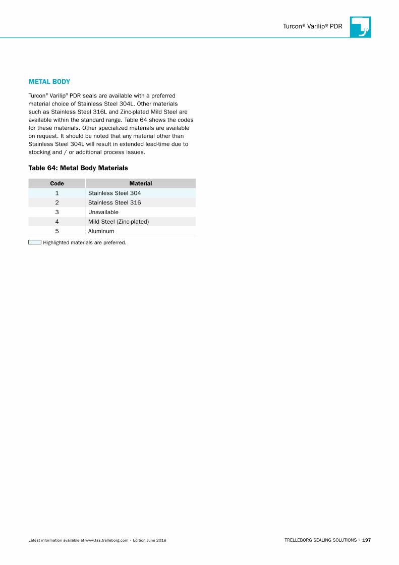
Turcon®Varilip®PDR
TRELLEBORG SEALING SOLUTIONS • 197Latest information available at www.tss.trelleborg.com • Edition June 2018
METAL BODY
Turcon®Varilip®PDR seals are available with a preferred material choice of Stainless Steel 304L. Other materials such as Stainless Steel 316L and Zinc-plated Mild Steel are available within the standard range. Table 64 shows the codes for these materials. Other specialized materials are available on request. It should be noted that any material other than Stainless Steel 304L will result in extended lead-time due to stocking and / or additional process issues.
Table 64: Metal Body Materials
Code Material
1 Stainless Steel 304
2 Stainless Steel 316
3 Unavailable
4 Mild Steel (Zinc-plated)
5 Aluminum
Highlighted materials are preferred.
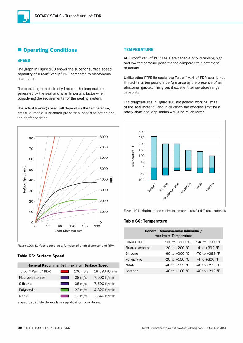
ROTARY SEALS · Turcon®Varilip®PDR
198 • TRELLEBORG SEALING SOLUTIONS Latest information available at www.tss.trelleborg.com • Edition June 2018
� Operating Conditions
SPEED
The graph in Figure 100 shows the superior surface speed capability of Turcon®Varilip®PDR compared to elastomeric shaft seals.
The operating speed directly impacts the temperature generated by the seal and is an important factor when considering the requirements for the sealing system.
The actual limiting speed will depend on the temperature, pressure, media, lubrication properties, heat dissipation and the shaft condition.
0
80
10
20
30
40
50
70
60
1000
00
2000
3000
4000
5000
6000
8000
7000
40 80Shaft Diameter mm
RPM
Sur
face
Spe
ed m
/s
120 160 200
Figure 100: Surface speed as a function of shaft diameter and RPM
Table 65: Surface Speed
General Recommended maximum Surface Speed
Turcon®Varilip®PDR 100 m/s 19,680 ft/min
Fluoroelastomer 38 m/s 7,500 ft/min
Silicone 38 m/s 7,500 ft/min
Polyacrylic 22 m/s 4,320 ft/min
Nitrile 12 m/s 2.340 ft/min
Speed capability depends on application conditions.
TEMPERATURE
All Turcon®Varilip®PDR seals are capable of outstanding high and low temperature performance compared to elastomeric materials.
Unlike other PTFE lip seals, the Turcon®Varilip®PDR seal is not limited in its temperature performance by the presence of an elastomer gasket. This gives it excellent temperature range capability.
The temperatures in Figure 101 are general working limits of the seal material, and in all cases the effective limit for a rotary shaft seal application would be much lower.
Turc
on®
Silic
one
Fluor
oelast
omer
Polya
cryli
c
Nitri
le
Leat
her
Tem
pera
ture
º C
-100
50
100
150
200
250
300
-50
0
Figure 101: Maximum and minimum temperatures for different materials
Table 66: Temperature
General Recommended minimum / maximum Temperature
Filled PTFE -100 to +260 °C -148 to +500 °F
Fluoroelastomer -20 to +200 °C -4 to +392 °F
Silicone -60 to +200 °C -76 to +392 °F
Polyacrylic -20 to +150 °C -4 to +300 °F
Nitrile -40 to +135 °C -40 to +275 °F
Leather -40 to +100 °C -40 to +212 °F
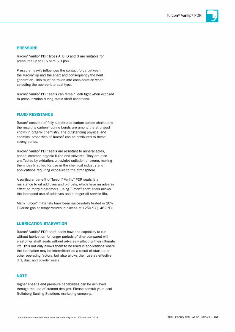
Turcon®Varilip®PDR
TRELLEBORG SEALING SOLUTIONS • 199Latest information available at www.tss.trelleborg.com • Edition June 2018
PRESSURE
Turcon®Varilip®PDR Types A, B, D and G are suitable for pressures up to 0.5 MPa (73 psi).
Pressure heavily influences the contact force between the Turcon®lip and the shaft and consequently the heat generation. This must be taken into consideration when selecting the appropriate seal type.
Turcon®Varilip®PDR seals can remain leak tight when exposed to pressurization during static shaft conditions.
FLUID RESISTANCE
Turcon®consists of fully substituted carbon-carbon chains and the resulting carbon-fluorine bonds are among the strongest known in organic chemistry. The outstanding physical and chemical properties of Turcon®can be attributed to these strong bonds.
Turcon®Varilip®PDR seals are resistant to mineral acids, bases, common organic fluids and solvents. They are also unaffected by oxidation, ultraviolet radiation or ozone, making them ideally suited for use in the chemical industry and applications requiring exposure to the atmosphere.
A particular benefit of Turcon®Varilip®PDR seals is a resistance to oil additives and biofuels, which have an adverse effect on many elastomers. Using Turcon®shaft seals allows the increased use of additives and a longer oil service life.
Many Turcon®materials have been successfully tested in 20% Fluorine gas at temperatures in excess of +250 °C (+482 °F).
LUBRICATION STARVATION
Turcon®Varilip®PDR shaft seals have the capability to run without lubrication for longer periods of time compared with elastomer shaft seals without adversely affecting their ultimate life. This not only allows them to be used in applications where the lubrication may be intermittent as a result of start up or other operating factors, but also allows their use as effective dirt, dust and powder seals.
NOTE
Higher speeds and pressure capabilities can be achieved through the use of custom designs. Please consult your local Trelleborg Sealing Solutions marketing company.
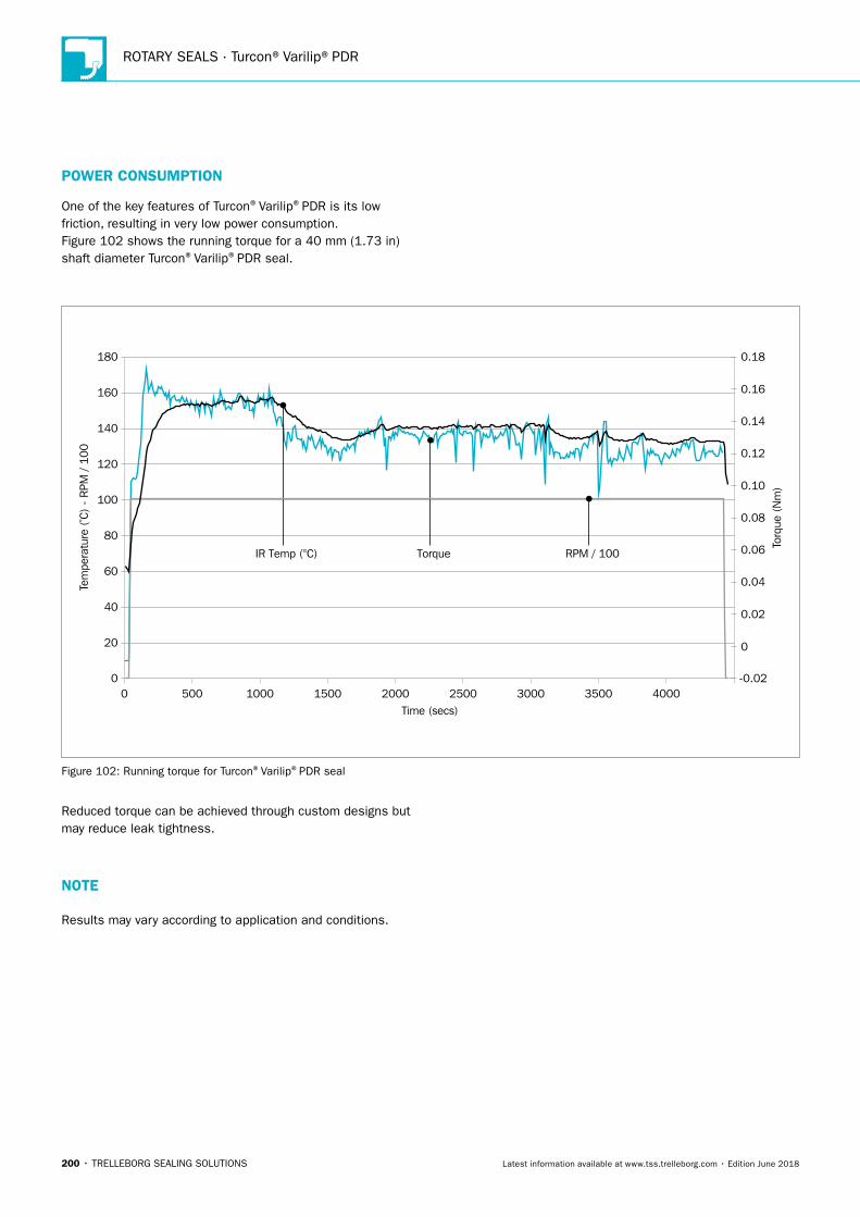
ROTARY SEALS · Turcon®Varilip®PDR
200 • TRELLEBORG SEALING SOLUTIONS Latest information available at www.tss.trelleborg.com • Edition June 2018
POWER CONSUMPTION
One of the key features of Turcon®Varilip®PDR is its low friction, resulting in very low power consumption.Figure 102 shows the running torque for a 40 mm (1.73 in) shaft diameter Turcon®Varilip®PDR seal.
Tem
pera
ture
(º C
) -
RPM
/ 10
0
Time (secs)
Torq
ue (
Nm
)
IR Temp (°C) RPM / 100 Torque
0
0
0 500 1000 1500 2000 2500 3000 3500 4000
20
40
60
80
100
120
140
160
180
0.02
0.06
0.08
0.10
0.12
0.14
0.16
0.18
-0.02
0.04
Figure 102: Running torque for Turcon®Varilip®PDR seal
Reduced torque can be achieved through custom designs but may reduce leak tightness.
NOTE
Results may vary according to application and conditions.
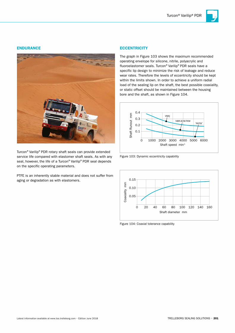
Turcon®Varilip®PDR
TRELLEBORG SEALING SOLUTIONS • 201Latest information available at www.tss.trelleborg.com • Edition June 2018
ENDURANCE
Turcon®Varilip®PDR rotary shaft seals can provide extended service life compared with elastomer shaft seals. As with any seal, however, the life of a Turcon®Varilip®PDR seal depends on the specific operating parameters.
PTFE is an inherently stable material and does not suffer from aging or degradation as with elastomers.
ECCENTRICITY
The graph in Figure 103 shows the maximum recommended operating envelope for silicone, nitrile, polyacrylic and fluoroelastomer seals. Turcon®Varilip®PDR seals have a specific lip design to minimize the risk of leakage and reduce wear rates. Therefore the levels of eccentricity should be kept within the limits shown. In order to achieve a uniform radial load of the sealing lip on the shaft, the best possible coaxiality, or static offset should be maintained between the housing bore and the shaft, as shown in Figure 104.
0
0.1
0.2
0.3
0.4
1000 2000Shaft speed min-1
Sha
ft R
unou
t m
m
VMQ
3000 4000 5000 6000
NBR-ACM-FKMVarilip®
Figure 103: Dynamic eccentricity capability
0
0.05
0.10
0.15
20 40 60 80 100 120 140 160
Shaft diameter mm
Coa
xial
ity m
m
Figure 104: Coaxial tolerance capability
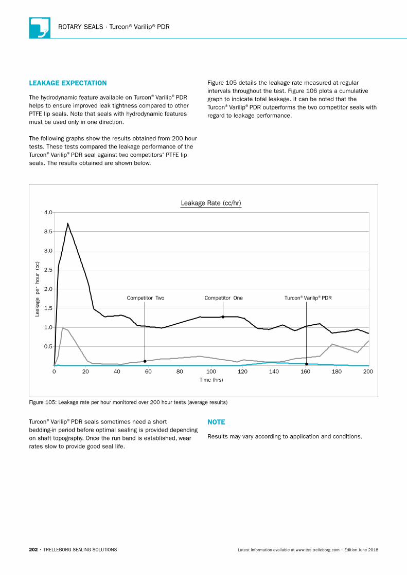
ROTARY SEALS · Turcon®Varilip®PDR
202 • TRELLEBORG SEALING SOLUTIONS Latest information available at www.tss.trelleborg.com • Edition June 2018
LEAKAGE EXPECTATION
The hydrodynamic feature available on Turcon®Varilip®PDR helps to ensure improved leak tightness compared to other PTFE lip seals. Note that seals with hydrodynamic features must be used only in one direction.
The following graphs show the results obtained from 200 hour tests. These tests compared the leakage performance of the Turcon®Varilip®PDR seal against two competitors' PTFE lip seals. The results obtained are shown below.
Figure 105 details the leakage rate measured at regular intervals throughout the test. Figure 106 plots a cumulative graph to indicate total leakage. It can be noted that the Turcon®Varilip®PDR outperforms the two competitor seals with regard to leakage performance.
Leak
age
per
hour
(cc
)
Competitor One Competitor Two Turcon® Varilip® PDR
Leakage Rate (cc/hr)
Time (hrs)
0
0.5
1.0
1.5
2.0
2.5
3.0
3.5
4.0
20 40 60 80 100 120 140 160 180 200
Figure 105: Leakage rate per hour monitored over 200 hour tests (average results)
Turcon®Varilip®PDR seals sometimes need a short bedding-in period before optimal sealing is provided depending on shaft topography. Once the run band is established, wear rates slow to provide good seal life.
NOTE
Results may vary according to application and conditions.
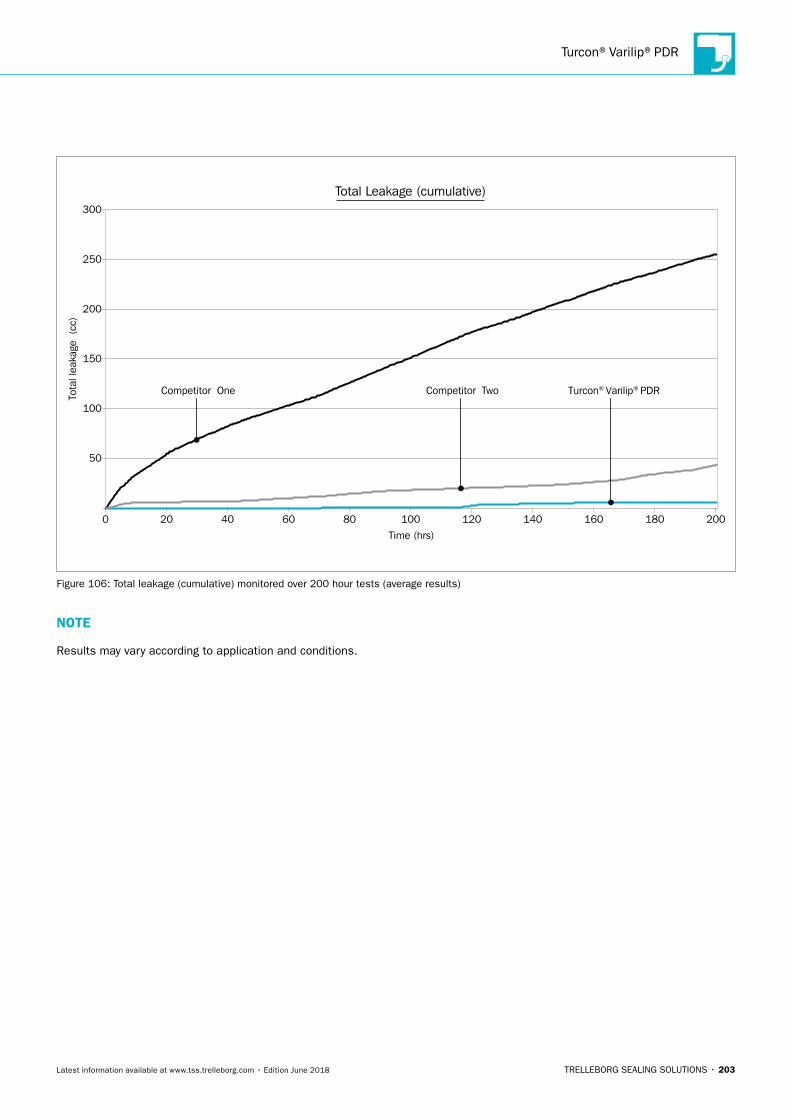
Turcon®Varilip®PDR
TRELLEBORG SEALING SOLUTIONS • 203Latest information available at www.tss.trelleborg.com • Edition June 2018
Tota
l lea
kage
(cc
)
Competitor One Competitor Two Turcon® Varilip® PDR
Total Leakage (cumulative)
Time (hrs)
0
50
100
150
200
250
300
20 40 60 80 100 120 140 160 180 200
Figure 106: Total leakage (cumulative) monitored over 200 hour tests (average results)
NOTE
Results may vary according to application and conditions.
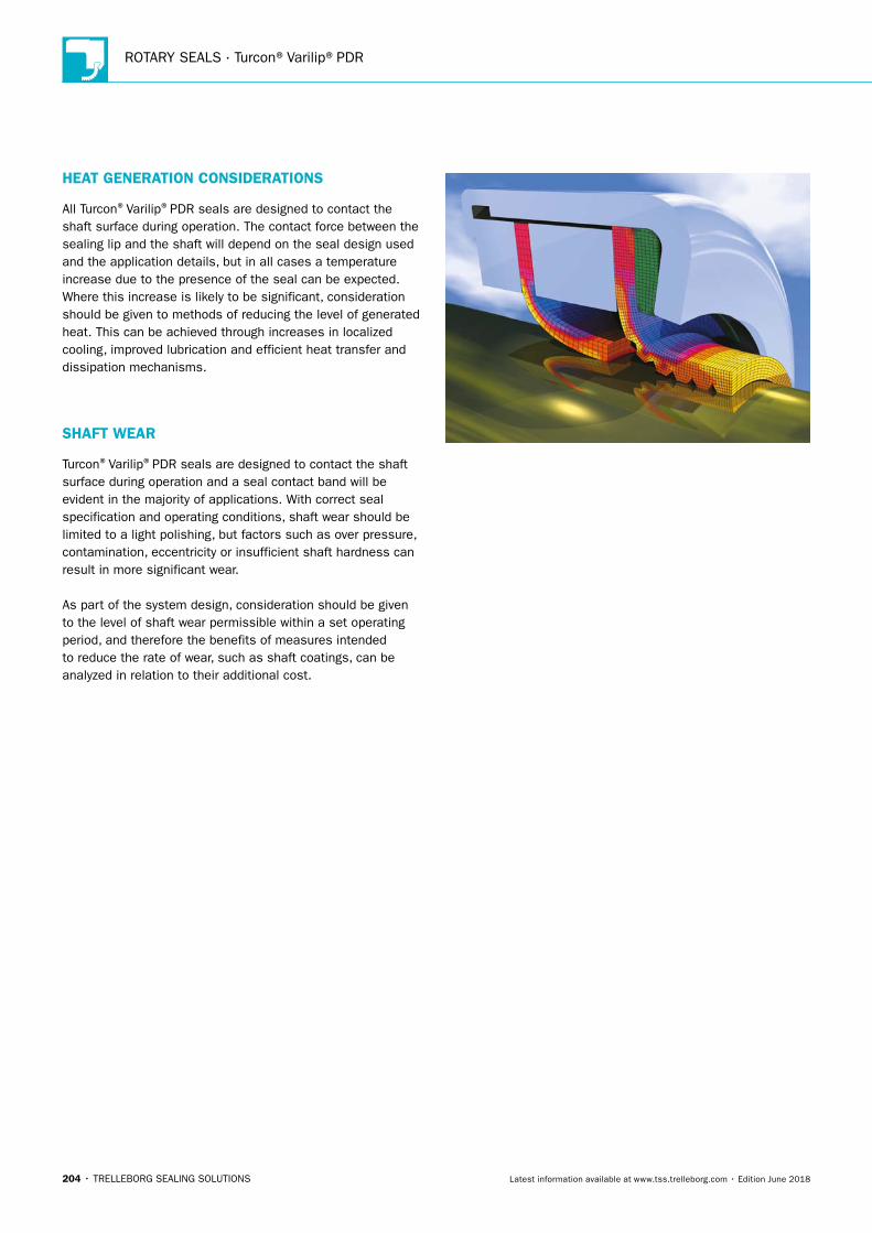
ROTARY SEALS · Turcon®Varilip®PDR
204 • TRELLEBORG SEALING SOLUTIONS Latest information available at www.tss.trelleborg.com • Edition June 2018
HEAT GENERATION CONSIDERATIONS
All Turcon®Varilip®PDR seals are designed to contact the shaft surface during operation. The contact force between the sealing lip and the shaft will depend on the seal design used and the application details, but in all cases a temperature increase due to the presence of the seal can be expected. Where this increase is likely to be significant, consideration should be given to methods of reducing the level of generated heat. This can be achieved through increases in localized cooling, improved lubrication and efficient heat transfer and dissipation mechanisms.
SHAFT WEAR
Turcon®Varilip®PDR seals are designed to contact the shaft surface during operation and a seal contact band will be evident in the majority of applications. With correct seal specification and operating conditions, shaft wear should be limited to a light polishing, but factors such as over pressure, contamination, eccentricity or insufficient shaft hardness can result in more significant wear.
As part of the system design, consideration should be given to the level of shaft wear permissible within a set operating period, and therefore the benefits of measures intended to reduce the rate of wear, such as shaft coatings, can be analyzed in relation to their additional cost.
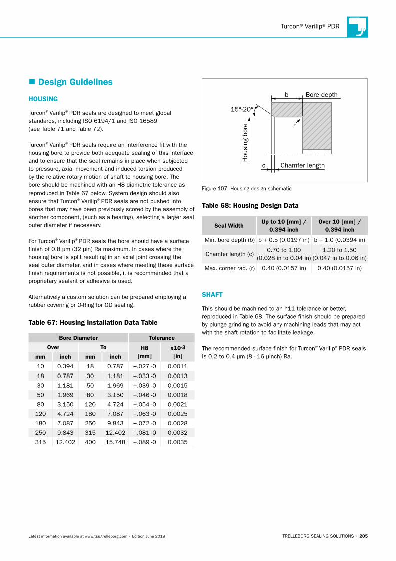
Turcon®Varilip®PDR
TRELLEBORG SEALING SOLUTIONS • 205Latest information available at www.tss.trelleborg.com • Edition June 2018
� Design Guidelines
HOUSING
Turcon®Varilip®PDR seals are designed to meet global standards, including ISO 6194/1 and ISO 16589 (see Table 71 and Table 72).
Turcon®Varilip®PDR seals require an interference fit with the housing bore to provide both adequate sealing of this interface and to ensure that the seal remains in place when subjected to pressure, axial movement and induced torsion produced by the relative rotary motion of shaft to housing bore. The bore should be machined with an H8 diametric tolerance as reproduced in Table 67 below. System design should also ensure that Turcon®Varilip®PDR seals are not pushed into bores that may have been previously scored by the assembly of another component, (such as a bearing), selecting a larger seal outer diameter if necessary.
For Turcon®Varilip®PDR seals the bore should have a surface finish of 0.8 μm (32 μin) Ra maximum. In cases where the housing bore is split resulting in an axial joint crossing the seal outer diameter, and in cases where meeting these surface finish requirements is not possible, it is recommended that a proprietary sealant or adhesive is used.
Alternatively a custom solution can be prepared employing a rubber covering or O-Ring for OD sealing.
Table 67: Housing Installation Data Table
Bore Diameter Tolerance
Over To H8 [mm]
x10-3
[in]mm inch mm inch
10 0.394 18 0.787 +.027 -0 0.0011
18 0.787 30 1.181 +.033 -0 0.0013
30 1.181 50 1.969 +.039 -0 0.0015
50 1.969 80 3.150 +.046 -0 0.0018
80 3.150 120 4.724 +.054 -0 0.0021
120 4.724 180 7.087 +.063 -0 0.0025
180 7.087 250 9.843 +.072 -0 0.0028
250 9.843 315 12.402 +.081 -0 0.0032
315 12.402 400 15.748 +.089 -0 0.0035
Chamfer length
Hou
sing
bor
e
c
b
r
Bore depth
15°-20°
Figure 107: Housing design schematic
Table 68: Housing Design Data
Seal WidthUp to 10 [mm] /
0.394 inchOver 10 [mm] /
0.394 inch
Min. bore depth (b) b + 0.5 (0.0197 in) b + 1.0 (0.0394 in)
Chamfer length (c)0.70 to 1.00
(0.028 in to 0.04 in)1.20 to 1.50
(0.047 in to 0.06 in)
Max. corner rad. (r) 0.40 (0.0157 in) 0.40 (0.0157 in)
SHAFT
This should be machined to an h11 tolerance or better, reproduced in Table 68. The surface finish should be prepared by plunge grinding to avoid any machining leads that may act with the shaft rotation to facilitate leakage.
The recommended surface finish for Turcon®Varilip®PDR seals is 0.2 to 0.4 μm (8 - 16 μinch) Ra.
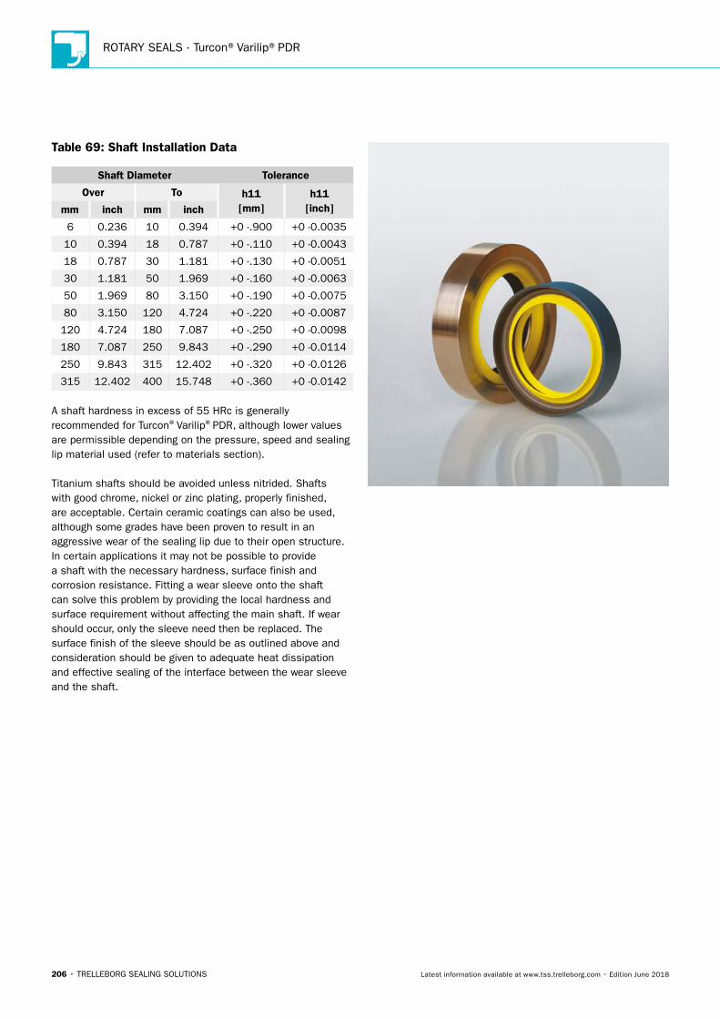
ROTARY SEALS · Turcon®Varilip®PDR
206 • TRELLEBORG SEALING SOLUTIONS Latest information available at www.tss.trelleborg.com • Edition June 2018
Table 69: Shaft Installation Data
Shaft Diameter Tolerance
Over To h11 [mm]
h11 [inch]mm inch mm inch
6 0.236 10 0.394 +0 -.900 +0 -0.0035
10 0.394 18 0.787 +0 -.110 +0 -0.0043
18 0.787 30 1.181 +0 -.130 +0 -0.0051
30 1.181 50 1.969 +0 -.160 +0 -0.0063
50 1.969 80 3.150 +0 -.190 +0 -0.0075
80 3.150 120 4.724 +0 -.220 +0 -0.0087
120 4.724 180 7.087 +0 -.250 +0 -0.0098
180 7.087 250 9.843 +0 -.290 +0 -0.0114
250 9.843 315 12.402 +0 -.320 +0 -0.0126
315 12.402 400 15.748 +0 -.360 +0 -0.0142
A shaft hardness in excess of 55 HRc is generally recommended for Turcon®Varilip®PDR, although lower values are permissible depending on the pressure, speed and sealing lip material used (refer to materials section).
Titanium shafts should be avoided unless nitrided. Shafts with good chrome, nickel or zinc plating, properly finished, are acceptable. Certain ceramic coatings can also be used, although some grades have been proven to result in an aggressive wear of the sealing lip due to their open structure. In certain applications it may not be possible to provide a shaft with the necessary hardness, surface finish and corrosion resistance. Fitting a wear sleeve onto the shaft can solve this problem by providing the local hardness and surface requirement without affecting the main shaft. If wear should occur, only the sleeve need then be replaced. The surface finish of the sleeve should be as outlined above and consideration should be given to adequate heat dissipation and effective sealing of the interface between the wear sleeve and the shaft.
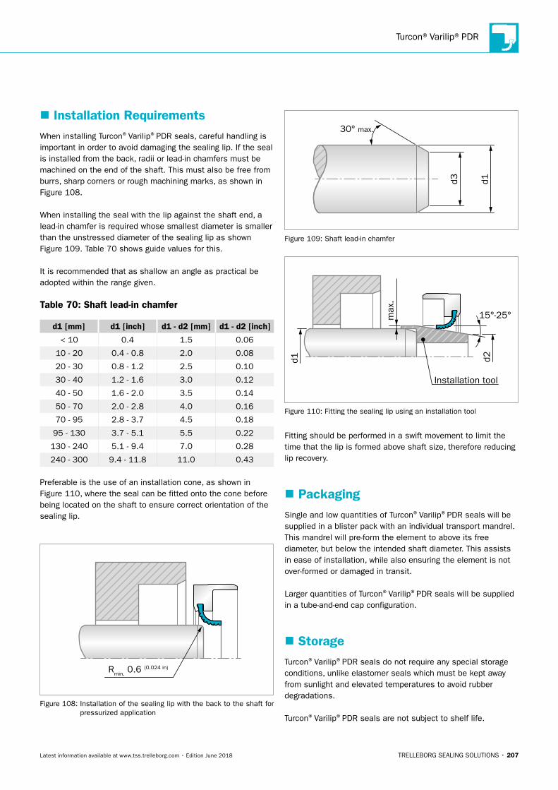
Turcon®Varilip®PDR
TRELLEBORG SEALING SOLUTIONS • 207Latest information available at www.tss.trelleborg.com • Edition June 2018
� Installation RequirementsWhen installing Turcon®Varilip®PDR seals, careful handling is important in order to avoid damaging the sealing lip. If the seal is installed from the back, radii or lead-in chamfers must be machined on the end of the shaft. This must also be free from burrs, sharp corners or rough machining marks, as shown in Figure 108.
When installing the seal with the lip against the shaft end, a lead-in chamfer is required whose smallest diameter is smaller than the unstressed diameter of the sealing lip as shown Figure 109. Table 70 shows guide values for this.
It is recommended that as shallow an angle as practical be adopted within the range given.
Table 70: Shaft lead-in chamfer
d1 [mm] d1 [inch] d1 - d2 [mm] d1 - d2 [inch]
< 10 0.4 1.5 0.06
10 - 20 0.4 - 0.8 2.0 0.08
20 - 30 0.8 - 1.2 2.5 0.10
30 - 40 1.2 - 1.6 3.0 0.12
40 - 50 1.6 - 2.0 3.5 0.14
50 - 70 2.0 - 2.8 4.0 0.16
70 - 95 2.8 - 3.7 4.5 0.18
95 - 130 3.7 - 5.1 5.5 0.22
130 - 240 5.1 - 9.4 7.0 0.28
240 - 300 9.4 - 11.8 11.0 0.43
Preferable is the use of an installation cone, as shown in Figure 110, where the seal can be fitted onto the cone before being located on the shaft to ensure correct orientation of the sealing lip.
Rmin. 0.6 (0.024 in)
Figure 108: Installation of the sealing lip with the back to the shaft for pressurized application
d3 d1
30° max.
Figure 109: Shaft lead-in chamfer
Installation tool
d2d1
max
.
15°-25°
Figure 110: Fitting the sealing lip using an installation tool
Fitting should be performed in a swift movement to limit the time that the lip is formed above shaft size, therefore reducing lip recovery.
� PackagingSingle and low quantities of Turcon®Varilip®PDR seals will be supplied in a blister pack with an individual transport mandrel. This mandrel will pre-form the element to above its free diameter, but below the intended shaft diameter. This assists in ease of installation, while also ensuring the element is not over-formed or damaged in transit.
Larger quantities of Turcon®Varilip®PDR seals will be supplied in a tube-and-end cap configuration.
� StorageTurcon®Varilip®PDR seals do not require any special storage conditions, unlike elastomer seals which must be kept away from sunlight and elevated temperatures to avoid rubber degradations.
Turcon®Varilip®PDR seals are not subject to shelf life.
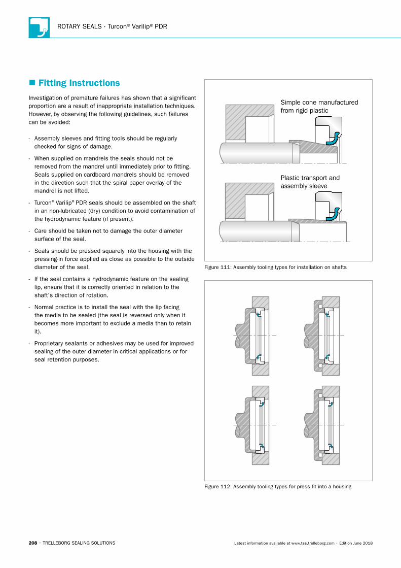
ROTARY SEALS · Turcon®Varilip®PDR
208 • TRELLEBORG SEALING SOLUTIONS Latest information available at www.tss.trelleborg.com • Edition June 2018
� Fitting InstructionsInvestigation of premature failures has shown that a significant proportion are a result of inappropriate installation techniques. However, by observing the following guidelines, such failures can be avoided:
- Assembly sleeves and fitting tools should be regularly checked for signs of damage.
- When supplied on mandrels the seals should not be removed from the mandrel until immediately prior to fitting. Seals supplied on cardboard mandrels should be removed in the direction such that the spiral paper overlay of the mandrel is not lifted.
- Turcon®Varilip®PDR seals should be assembled on the shaft in an non-lubricated (dry) condition to avoid contamination of the hydrodynamic feature (if present).
- Care should be taken not to damage the outer diameter surface of the seal.
- Seals should be pressed squarely into the housing with the pressing-in force applied as close as possible to the outside diameter of the seal.
- If the seal contains a hydrodynamic feature on the sealing lip, ensure that it is correctly oriented in relation to the shaft's direction of rotation.
- Normal practice is to install the seal with the lip facing the media to be sealed (the seal is reversed only when it becomes more important to exclude a media than to retain it).
- Proprietary sealants or adhesives may be used for improved sealing of the outer diameter in critical applications or for seal retention purposes.
Plastic transport andassembly sleeve
Simple cone manufacturedfrom rigid plastic
Figure 111: Assembly tooling types for installation on shafts
Figure 112: Assembly tooling types for press fit into a housing
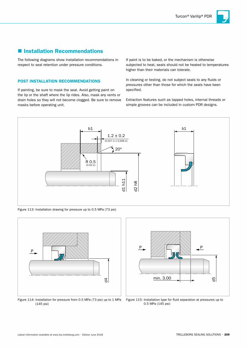
Turcon®Varilip®PDR
TRELLEBORG SEALING SOLUTIONS • 209Latest information available at www.tss.trelleborg.com • Edition June 2018
The following diagrams show installation recommendations in respect to seal retention under pressure conditions.
POST INSTALLATION RECOMMENDATIONS
If painting, be sure to mask the seal. Avoid getting paint on the lip or the shaft where the lip rides. Also, mask any vents or drain holes so they will not become clogged. Be sure to remove masks before operating unit.
If paint is to be baked, or the mechanism is otherwise subjected to heat, seals should not be heated to temperatures higher than their materials can tolerate.
In cleaning or testing, do not subject seals to any fluids or pressures other than those for which the seals have been specified.
Extraction features such as tapped holes, internal threads or simple grooves can be included in custom PDR designs.
� Installation Recommendations
d1 h
11
d2 h
8
20°
1.2 ± 0.2
b1 b1
(0.047 in ± 0.008 in)
(0.02 in)R 0.5
Figure 113: Installation drawing for pressure up to 0.5 MPa (73 psi)
P
d4
Figure 114: Installation for pressure from 0.5 MPa (73 psi) up to 1 MPa (145 psi)
d5
PP
min. 3.00
Figure 115: Installation type for fluid separation at pressures up to 0.5 MPa (145 psi)
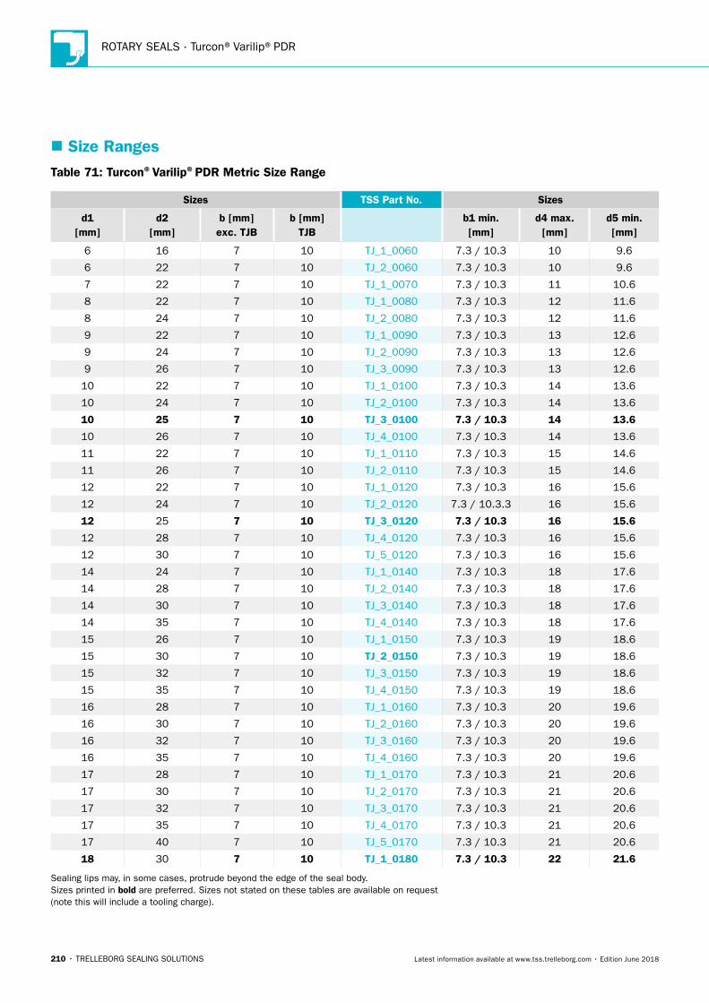
ROTARY SEALS · Turcon®Varilip®PDR
210 • TRELLEBORG SEALING SOLUTIONS Latest information available at www.tss.trelleborg.com • Edition June 2018
� Size RangesTable 71: Turcon®Varilip®PDR Metric Size Range
Sizes TSS Part No. Sizes
d1 [mm]
d2 [mm]
b [mm] exc. TJB
b [mm] TJB
b1 min. [mm]
d4 max. [mm]
d5 min. [mm]
6 16 7 10 TJ_1_0060 7.3 / 10.3 10 9.6
6 22 7 10 TJ_2_0060 7.3 / 10.3 10 9.6
7 22 7 10 TJ_1_0070 7.3 / 10.3 11 10.6
8 22 7 10 TJ_1_0080 7.3 / 10.3 12 11.6
8 24 7 10 TJ_2_0080 7.3 / 10.3 12 11.6
9 22 7 10 TJ_1_0090 7.3 / 10.3 13 12.6
9 24 7 10 TJ_2_0090 7.3 / 10.3 13 12.6
9 26 7 10 TJ_3_0090 7.3 / 10.3 13 12.6
10 22 7 10 TJ_1_0100 7.3 / 10.3 14 13.6
10 24 7 10 TJ_2_0100 7.3 / 10.3 14 13.6
10 25 7 10 TJ_3_0100 7.3 / 10.3 14 13.6
10 26 7 10 TJ_4_0100 7.3 / 10.3 14 13.6
11 22 7 10 TJ_1_0110 7.3 / 10.3 15 14.6
11 26 7 10 TJ_2_0110 7.3 / 10.3 15 14.6
12 22 7 10 TJ_1_0120 7.3 / 10.3 16 15.6
12 24 7 10 TJ_2_0120 7.3 / 10.3.3 16 15.6
12 25 7 10 TJ_3_0120 7.3 / 10.3 16 15.6
12 28 7 10 TJ_4_0120 7.3 / 10.3 16 15.6
12 30 7 10 TJ_5_0120 7.3 / 10.3 16 15.6
14 24 7 10 TJ_1_0140 7.3 / 10.3 18 17.6
14 28 7 10 TJ_2_0140 7.3 / 10.3 18 17.6
14 30 7 10 TJ_3_0140 7.3 / 10.3 18 17.6
14 35 7 10 TJ_4_0140 7.3 / 10.3 18 17.6
15 26 7 10 TJ_1_0150 7.3 / 10.3 19 18.6
15 30 7 10 TJ_2_0150 7.3 / 10.3 19 18.6
15 32 7 10 TJ_3_0150 7.3 / 10.3 19 18.6
15 35 7 10 TJ_4_0150 7.3 / 10.3 19 18.6
16 28 7 10 TJ_1_0160 7.3 / 10.3 20 19.6
16 30 7 10 TJ_2_0160 7.3 / 10.3 20 19.6
16 32 7 10 TJ_3_0160 7.3 / 10.3 20 19.6
16 35 7 10 TJ_4_0160 7.3 / 10.3 20 19.6
17 28 7 10 TJ_1_0170 7.3 / 10.3 21 20.6
17 30 7 10 TJ_2_0170 7.3 / 10.3 21 20.6
17 32 7 10 TJ_3_0170 7.3 / 10.3 21 20.6
17 35 7 10 TJ_4_0170 7.3 / 10.3 21 20.6
17 40 7 10 TJ_5_0170 7.3 / 10.3 21 20.6
18 30 7 10 TJ_1_0180 7.3 / 10.3 22 21.6
Sealing lips may, in some cases, protrude beyond the edge of the seal body. Sizes printed in bold are preferred. Sizes not stated on these tables are available on request (note this will include a tooling charge).
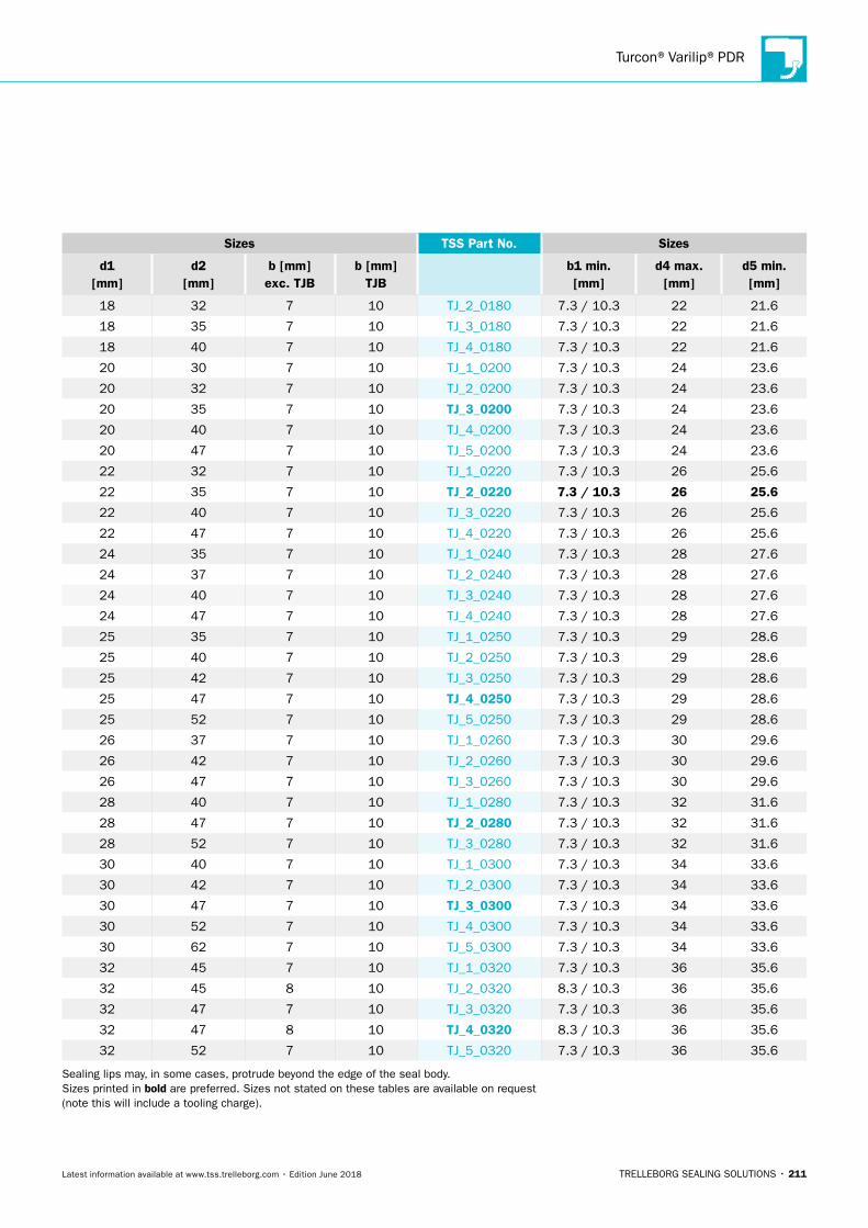
Turcon®Varilip®PDR
TRELLEBORG SEALING SOLUTIONS • 211Latest information available at www.tss.trelleborg.com • Edition June 2018
Sizes TSS Part No. Sizes
d1 [mm]
d2 [mm]
b [mm] exc. TJB
b [mm] TJB
b1 min. [mm]
d4 max. [mm]
d5 min. [mm]
18 32 7 10 TJ_2_0180 7.3 / 10.3 22 21.6
18 35 7 10 TJ_3_0180 7.3 / 10.3 22 21.6
18 40 7 10 TJ_4_0180 7.3 / 10.3 22 21.6
20 30 7 10 TJ_1_0200 7.3 / 10.3 24 23.6
20 32 7 10 TJ_2_0200 7.3 / 10.3 24 23.6
20 35 7 10 TJ_3_0200 7.3 / 10.3 24 23.6
20 40 7 10 TJ_4_0200 7.3 / 10.3 24 23.6
20 47 7 10 TJ_5_0200 7.3 / 10.3 24 23.6
22 32 7 10 TJ_1_0220 7.3 / 10.3 26 25.6
22 35 7 10 TJ_2_0220 7.3 / 10.3 26 25.6
22 40 7 10 TJ_3_0220 7.3 / 10.3 26 25.6
22 47 7 10 TJ_4_0220 7.3 / 10.3 26 25.6
24 35 7 10 TJ_1_0240 7.3 / 10.3 28 27.6
24 37 7 10 TJ_2_0240 7.3 / 10.3 28 27.6
24 40 7 10 TJ_3_0240 7.3 / 10.3 28 27.6
24 47 7 10 TJ_4_0240 7.3 / 10.3 28 27.6
25 35 7 10 TJ_1_0250 7.3 / 10.3 29 28.6
25 40 7 10 TJ_2_0250 7.3 / 10.3 29 28.6
25 42 7 10 TJ_3_0250 7.3 / 10.3 29 28.6
25 47 7 10 TJ_4_0250 7.3 / 10.3 29 28.6
25 52 7 10 TJ_5_0250 7.3 / 10.3 29 28.6
26 37 7 10 TJ_1_0260 7.3 / 10.3 30 29.6
26 42 7 10 TJ_2_0260 7.3 / 10.3 30 29.6
26 47 7 10 TJ_3_0260 7.3 / 10.3 30 29.6
28 40 7 10 TJ_1_0280 7.3 / 10.3 32 31.6
28 47 7 10 TJ_2_0280 7.3 / 10.3 32 31.6
28 52 7 10 TJ_3_0280 7.3 / 10.3 32 31.6
30 40 7 10 TJ_1_0300 7.3 / 10.3 34 33.6
30 42 7 10 TJ_2_0300 7.3 / 10.3 34 33.6
30 47 7 10 TJ_3_0300 7.3 / 10.3 34 33.6
30 52 7 10 TJ_4_0300 7.3 / 10.3 34 33.6
30 62 7 10 TJ_5_0300 7.3 / 10.3 34 33.6
32 45 7 10 TJ_1_0320 7.3 / 10.3 36 35.6
32 45 8 10 TJ_2_0320 8.3 / 10.3 36 35.6
32 47 7 10 TJ_3_0320 7.3 / 10.3 36 35.6
32 47 8 10 TJ_4_0320 8.3 / 10.3 36 35.6
32 52 7 10 TJ_5_0320 7.3 / 10.3 36 35.6
Sealing lips may, in some cases, protrude beyond the edge of the seal body. Sizes printed in bold are preferred. Sizes not stated on these tables are available on request (note this will include a tooling charge).
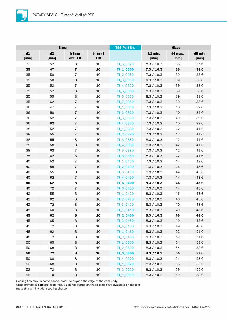
ROTARY SEALS · Turcon®Varilip®PDR
212 • TRELLEBORG SEALING SOLUTIONS Latest information available at www.tss.trelleborg.com • Edition June 2018
Sizes TSS Part No. Sizes
d1 [mm]
d2 [mm]
b [mm] exc. TJB
b [mm] TJB
b1 min. [mm]
d4 max. [mm]
d5 min. [mm]
32 52 8 10 TJ_6_0320 8.3 / 10.3 36 35.6
35 47 7 10 TJ_1_0350 7.3 / 10.3 39 38.6
35 50 7 10 TJ_2_0350 7.3 / 10.3 39 38.6
35 50 8 10 TJ_3_0350 8.3 / 10.3 39 38.6
35 52 7 10 TJ_4_0350 7.3 / 10.3 39 38.6
35 52 8 10 TJ_5_0350 8.3 / 10.3 39 38.6
35 55 8 10 TJ_6_0350 8.3 / 10.3 39 38.6
35 62 7 10 TJ_7_0350 7.3 / 10.3 39 38.6
36 47 7 10 TJ_1_0360 7.3 / 10.3 40 39.6
36 50 7 10 TJ_2_0360 7.3 / 10.3 40 39.6
36 52 7 10 TJ_3_0360 7.3 / 10.3 40 39.6
36 62 7 10 TJ_4_0360 7.3 / 10.3 40 39.6
38 52 7 10 TJ_1_0380 7.3 / 10.3 42 41.6
38 55 7 10 TJ_2_0380 7.3 / 10.3 42 41.6
38 55 8 10 TJ_3_0380 8.3 / 10.3 42 41.6
38 58 8 10 TJ_4_0380 8.3 / 10.3 42 41.6
38 62 7 10 TJ_5_0380 7.3 / 10.3 42 41.6
38 62 8 10 TJ_6_0380 8.3 / 10.3 42 41.6
40 52 7 10 TJ_1_0400 7.3 / 10.3 44 43.6
40 55 7 10 TJ_2_0400 7.3 / 10.3 44 43.6
40 55 8 10 TJ_3_0400 8.3 / 10.3 44 43.6
40 62 7 10 TJ_4_0400 7.3 / 10.3 44 43.6
40 62 8 10 TJ_5_0400 8.3 / 10.3 44 43.6
40 72 7 10 TJ_6_0400 7.3 / 10.3 44 43.6
42 55 8 10 TJ_1_0420 8.3 / 10.3 46 45.6
42 62 8 10 TJ_2_0420 8.3 / 10.3 46 45.6
42 72 8 10 TJ_3_0420 8.3 / 10.3 49 48.6
45 60 8 10 TJ_1_0450 8.3 / 10.3 49 48.6
45 62 8 10 TJ_2_0450 8.3 / 10.3 49 48.6
45 65 8 10 TJ_3_0450 8.3 / 10.3 49 48.6
45 72 8 10 TJ_4_0450 8.3 / 10.3 49 48.6
48 62 8 10 TJ_1_0480 8.3 / 10.3 52 51.6
48 72 8 10 TJ_2_0480 8.3 / 10.3 52 51.6
50 65 8 10 TJ_1_0500 8.3 / 10.3 54 53.6
50 68 8 10 TJ_2_0500 8.3 / 10.3 54 53.6
50 72 8 10 TJ_3_0500 8.3 / 10.3 54 53.6
50 80 8 10 TJ_4_0500 8.3 / 10.3 54 53.6
52 68 8 10 TJ_1_0520 8.3 / 10.3 56 55.6
52 72 8 10 TJ_2_0520 8.3 / 10.3 59 55.6
55 70 8 10 TJ_1_0550 8.3 / 10.3 59 58.6
Sealing lips may, in some cases, protrude beyond the edge of the seal body. Sizes printed in bold are preferred. Sizes not stated on these tables are available on request (note this will include a tooling charge).
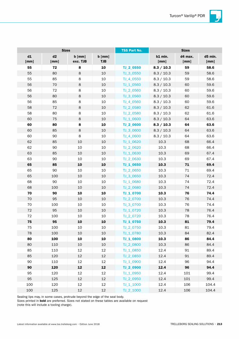
Turcon®Varilip®PDR
TRELLEBORG SEALING SOLUTIONS • 213Latest information available at www.tss.trelleborg.com • Edition June 2018
Sizes TSS Part No. Sizes
d1 [mm]
d2 [mm]
b [mm] exc. TJB
b [mm] TJB
b1 min. [mm]
d4 max. [mm]
d5 min. [mm]
55 72 8 10 TJ_2_0550 8.3 / 10.3 59 58.6
55 80 8 10 TJ_3_0550 8.3 / 10.3 59 58.6
55 85 8 10 TJ_4_0550 8.3 / 10.3 59 58.6
56 70 8 10 TJ_1_0560 8.3 / 10.3 60 59.6
56 72 8 10 TJ_2_0560 8.3 / 10.3 60 59.6
56 80 8 10 TJ_3_0560 8.3 / 10.3 60 59.6
56 85 8 10 TJ_4_0560 8.3 / 10.3 60 59.6
58 72 8 10 TJ_2_0580 8.3 / 10.3 62 61.6
58 80 8 10 TJ_2_0580 8.3 / 10.3 62 61.6
60 75 8 10 TJ_1_0600 8.3 / 10.3 64 63.6
60 80 8 10 TJ_2_0600 8.3 / 10.3 64 63.6
60 85 8 10 TJ_3_0600 8.3 / 10.3 64 63.6
60 90 8 10 TJ_4_0600 8.3 / 10.3 64 63.6
62 85 10 10 TJ_1_0620 10.3 68 66.4
62 90 10 10 TJ_2_0620 10.3 68 66.4
63 85 10 10 TJ_1_0630 10.3 69 67.4
63 90 10 10 TJ_2_0630 10.3 69 67.4
65 85 10 10 TJ_1_0650 10.3 71 69.4
65 90 10 10 TJ_2_0650 10.3 71 69.4
65 100 10 10 TJ_3_0650 10.3 74 72.4
68 90 10 10 TJ_1_0680 10.3 74 72.4
68 100 10 10 TJ_2_0680 10.3 74 72.4
70 90 10 10 TJ_1_0700 10.3 76 74.4
70 95 10 10 TJ_2_0700 10.3 76 74.4
70 100 10 10 TJ_3_0700 10.3 76 74.4
72 95 10 10 TJ_1_0720 10.3 78 76.4
72 100 10 10 TJ_2_0720 10.3 78 76.4
75 95 10 10 TJ_1_0750 10.3 81 79.4
75 100 10 10 TJ_2_0750 10.3 81 79.4
78 100 10 10 TJ_1_0780 10.3 84 82.4
80 100 10 10 TJ_1_0800 10.3 86 84.4
80 110 10 10 TJ_2_0800 10.3 86 84.4
85 110 12 12 TJ_1_0850 12.4 91 89.4
85 120 12 12 TJ_2_0850 12.4 91 89.4
90 110 12 12 TJ_1_0900 12.4 96 94.4
90 120 12 12 TJ_2_0900 12.4 96 94.4
95 120 12 12 TJ_1_0950 12.4 101 99.4
95 125 12 12 TJ_2_0950 12.4 101 99.4
100 120 12 12 TJ_1_1000 12.4 106 104.4
100 125 12 12 TJ_2_1000 12.4 106 104.4
Sealing lips may, in some cases, protrude beyond the edge of the seal body. Sizes printed in bold are preferred. Sizes not stated on these tables are available on request (note this will include a tooling charge).
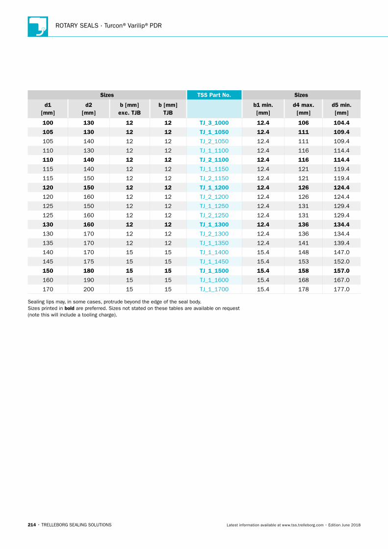
ROTARY SEALS · Turcon®Varilip®PDR
214 • TRELLEBORG SEALING SOLUTIONS Latest information available at www.tss.trelleborg.com • Edition June 2018
Sizes TSS Part No. Sizes
d1 [mm]
d2 [mm]
b [mm] exc. TJB
b [mm] TJB
b1 min. [mm]
d4 max. [mm]
d5 min. [mm]
100 130 12 12 TJ_3_1000 12.4 106 104.4
105 130 12 12 TJ_1_1050 12.4 111 109.4
105 140 12 12 TJ_2_1050 12.4 111 109.4
110 130 12 12 TJ_1_1100 12.4 116 114.4
110 140 12 12 TJ_2_1100 12.4 116 114.4
115 140 12 12 TJ_1_1150 12.4 121 119.4
115 150 12 12 TJ_2_1150 12.4 121 119.4
120 150 12 12 TJ_1_1200 12.4 126 124.4
120 160 12 12 TJ_2_1200 12.4 126 124.4
125 150 12 12 TJ_1_1250 12.4 131 129.4
125 160 12 12 TJ_2_1250 12.4 131 129.4
130 160 12 12 TJ_1_1300 12.4 136 134.4
130 170 12 12 TJ_2_1300 12.4 136 134.4
135 170 12 12 TJ_1_1350 12.4 141 139.4
140 170 15 15 TJ_1_1400 15.4 148 147.0
145 175 15 15 TJ_1_1450 15.4 153 152.0
150 180 15 15 TJ_1_1500 15.4 158 157.0
160 190 15 15 TJ_1_1600 15.4 168 167.0
170 200 15 15 TJ_1_1700 15.4 178 177.0
Sealing lips may, in some cases, protrude beyond the edge of the seal body. Sizes printed in bold are preferred. Sizes not stated on these tables are available on request (note this will include a tooling charge).
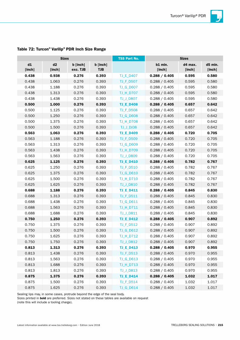
Turcon®Varilip®PDR
TRELLEBORG SEALING SOLUTIONS • 215Latest information available at www.tss.trelleborg.com • Edition June 2018
Table 72: Turcon®Varilip®PDR Inch Size Range
Sizes TSS Part No. Sizes
d1 [inch]
d2 [inch]
b [inch]exc. TJB
b [inch] TJB
b1 min. [inch]
d4 max. [inch]
d5 min. [inch]
0.438 0.938 0.276 0.393 TJ_E_D407 0.288 / 0.405 0.595 0.580
0.438 1.063 0.276 0.393 TJ_F_D507 0.288 / 0.405 0.595 0.580
0.438 1.188 0.276 0.393 TJ_G_D607 0.288 / 0.405 0.595 0.580
0.438 1.313 0.276 0.393 TJ_H_D707 0.288 / 0.405 0.595 0.580
0.438 1.438 0.276 0.393 TJ_J_D807 0.288 / 0.405 0.595 0.580
0.500 1.000 0.276 0.393 TJ_E_D408 0.288 / 0.405 0.657 0.642
0.500 1.125 0.276 0.393 TJ_F_D508 0.288 / 0.405 0.657 0.642
0.500 1.250 0.276 0.393 TJ_G_D608 0.288 / 0.405 0.657 0.642
0.500 1.375 0.276 0.393 TJ_H_D708 0.288 / 0.405 0.657 0.642
0.500 1.500 0.276 0.393 TJ_J_D(08 0.288 / 0.405 0.657 0.642
0.563 1.063 0.276 0.393 TJ_E_D409 0.288 / 0.405 0.720 0.705
0.563 1.188 0.276 0.393 TJ_F_D509 0.288 / 0.405 0.720 0.705
0.563 1.313 0.276 0.393 TJ_G_D609 0.288 / 0.405 0.720 0.705
0.563 1.438 0.276 0.393 TJ_H_D709 0.288 / 0.405 0.720 0.705
0.563 1.563 0.276 0.393 TJ_J_D809 0.288 / 0.405 0.720 0.705
0.625 1.125 0.276 0.393 TJ_E_D410 0.288 / 0.405 0.782 0.767
0.625 1.250 0.276 0.393 TJ_F_D510 0.288 / 0.405 0.782 0.767
0.625 1.375 0.276 0.393 TJ_G_D610 0.288 / 0.405 0.782 0.767
0.625 1.500 0.276 0.393 TJ_H_D710 0.288 / 0.405 0.782 0.767
0.625 1.625 0.276 0.393 TJ_J_D810 0.288 / 0.405 0.782 0.767
0.688 1.188 0.276 0.393 TJ_E_D411 0.288 / 0.405 0.845 0.830
0.688 1.313 0.276 0.393 TJ_F_D511 0.288 / 0.405 0.845 0.830
0.688 1.438 0.276 0.393 TJ_G_D611 0.288 / 0.405 0.845 0.830
0.688 1.563 0.276 0.393 TJ_H_D711 0.288 / 0.405 0.845 0.830
0.688 1.688 0.276 0.393 TJ_J_D811 0.288 / 0.405 0.845 0.830
0.750 1.250 0.276 0.393 TJ_E_D412 0.288 / 0.405 0.907 0.892
0.750 1.375 0.276 0.393 TJ_F_D512 0.288 / 0.405 0.907 0.892
0.750 1.500 0.276 0.393 TJ_G_D612 0.288 / 0.405 0.907 0.892
0.750 1.625 0.276 0.393 TJ_H_D712 0.288 / 0.405 0.907 0.892
0.750 1.750 0.276 0.393 TJ_J_D812 0.288 / 0.405 0.907 0.892
0.813 1.313 0.276 0.393 TJ_E_D413 0.288 / 0.405 0.970 0.955
0.813 1.438 0.276 0.393 TJ_F_D513 0.288 / 0.405 0.970 0.955
0.813 1.563 0.276 0.393 TJ_G_D613 0.288 / 0.405 0.970 0.955
0.813 1.688 0.276 0.393 TJ_H_D713 0.288 / 0.405 0.970 0.955
0.813 1.813 0.276 0.393 TJ_J_D813 0.288 / 0.405 0.970 0.955
0.875 1.375 0.276 0.393 TJ_E_D414 0.288 / 0.405 1.032 1.017
0.875 1.500 0.276 0.393 TJ_F_D514 0.288 / 0.405 1.032 1.017
0.875 1.625 0.276 0.393 TJ_G_D614 0.288 / 0.405 1.032 1.017
Sealing lips may, in some cases, protrude beyond the edge of the seal body. Sizes printed in bold are preferred. Sizes not stated on these tables are available on request (note this will include a tooling charge).
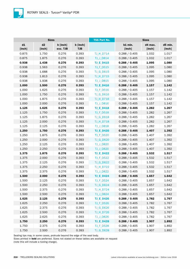
ROTARY SEALS · Turcon®Varilip®PDR
216 • TRELLEBORG SEALING SOLUTIONS Latest information available at www.tss.trelleborg.com • Edition June 2018
Sizes TSS Part No. Sizes
d1 [inch]
d2 [inch]
b [inch]exc. TJB
b [inch] TJB
b1 min. [inch]
d4 max. [inch]
d5 min. [inch]
0.875 1.750 0.276 0.393 TJ_H_D714 0.288 / 0.405 1.032 1.017
0.875 1.875 0.276 0.393 TJ_J_D814 0.288 / 0.405 1.032 1.017
0.938 1.438 0.276 0.393 TJ_E_D415 0.288 / 0.405 1.095 1.080
0.938 1.563 0.276 0.393 TJ_F_D515 0.288 / 0.405 1.095 1.080
0.938 1.688 0.276 0.393 TJ_G_D615 0.288 / 0.405 1.095 1.080
0.938 1.813 0.276 0.393 TJ_H_D715 0.288 / 0.405 1.095 1.080
0.938 1.938 0.276 0.393 TJ_J_D815 0.288 / 0.405 1.095 1.080
1.000 1.500 0.276 0.393 TJ_E_D416 0.288 / 0.405 1.157 1.142
1.000 1.625 0.276 0.393 TJ_F_D516 0.288 / 0.405 1.157 1.142
1.000 1.750 0.276 0.393 TJ_G_D616 0.288 / 0.405 1.157 1.142
1.000 1.875 0.276 0.393 TJ_H_D716 0.288 / 0.405 1.157 1.142
1.000 2.000 0.276 0.393 TJ_J_D816 0.288 / 0.405 1.157 1.142
1.125 1.625 0.276 0.393 TJ_E_D418 0.288 / 0.405 1.282 1.267
1.125 1.750 0.276 0.393 TJ_F_D518 0.288 / 0.405 1.282 1.267
1.125 1.875 0.276 0.393 TJ_G_D618 0.288 / 0.405 1.282 1.267
1.125 2.000 0.276 0.393 TJ_H_D718 0.288 / 0.405 1.282 1.267
1.125 2.125 0.276 0.393 TJ_J_D818 0.288 / 0.405 1.282 1.267
1.250 1.750 0.276 0.393 TJ_E_D420 0.288 / 0.405 1.407 1.392
1.250 1.875 0.276 0.393 TJ_F_D520 0.288 / 0.405 1.407 1.392
1.250 2.000 0.276 0.393 TJ_G_D620 0.288 / 0.405 1.407 1.392
1.250 2.125 0.276 0.393 TJ_J_D820 0.288 / 0.405 1.407 1.392
1.250 2.250 0.276 0.393 TJ_J_D820 0.288 / 0.405 1.407 1.392
1.375 1.875 0.276 0.393 TJ_E_D422 0.288 / 0.405 1.532 1.517
1.375 2.000 0.276 0.393 TJ_F_D522 0.288 / 0.405 1.532 1.517
1.375 2.125 0.276 0.393 TJ_G_D622 0.288 / 0.405 1.532 1.517
1.375 2.250 0.276 0.393 TJ_H_D722 0.288 / 0.405 1.532 1.517
1.375 2.375 0.276 0.393 TJ_J_D822 0.288 / 0.405 1.532 1.517
1.500 2.000 0.276 0.393 TJ_E_D424 0.288 / 0.405 1.657 1.642
1.500 2.125 0.276 0.393 TJ_F_D524 0.288 / 0.405 1.657 1.642
1.500 2.250 0.276 0.393 TJ_G_D624 0.288 / 0.405 1.657 1.642
1.500 2.375 0.276 0.393 TJ_H_D724 0.288 / 0.405 1.657 1.642
1.500 2.500 0.276 0.393 TJ_J_D824 0.288 / 0.405 1.657 1.642
1.625 2.125 0.276 0.393 TJ_E_D426 0.288 / 0.405 1.782 1.767
1.625 2.250 0.276 0.393 TJ_F_D526 0.288 / 0.405 1.782 1.767
1.625 2.375 0.276 0.393 TJ_G_D626 0.288 / 0.405 1.782 1.767
1.625 2.500 0.276 0.393 TJ_H_D726 0.288 / 0.405 1.782 1.767
1.625 2.625 0.276 0.393 TJ_J_D826 0.288 / 0.405 1.782 1.767
1.750 2.250 0.276 0.393 TJ_E_D428 0.288 / 0.405 1.907 1.892
1.750 2.375 0.276 0.393 TJ_F_D528 0.288 / 0.405 1.907 1.892
1.750 2.500 0.276 0.393 TJ_G_D628 0.288 / 0.405 1.907 1.892
Sealing lips may, in some cases, protrude beyond the edge of the seal body. Sizes printed in bold are preferred. Sizes not stated on these tables are available on request (note this will include a tooling charge).
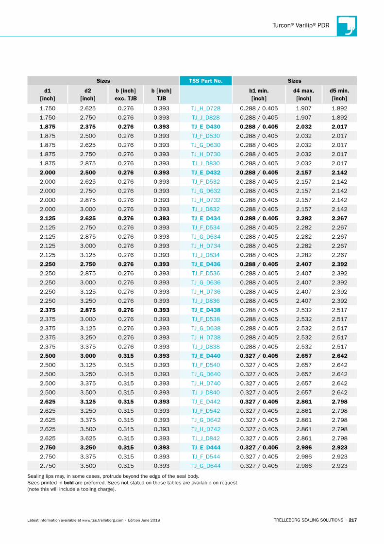
Turcon®Varilip®PDR
TRELLEBORG SEALING SOLUTIONS • 217Latest information available at www.tss.trelleborg.com • Edition June 2018
Sizes TSS Part No. Sizes
d1 [inch]
d2 [inch]
b [inch]exc. TJB
b [inch] TJB
b1 min. [inch]
d4 max. [inch]
d5 min. [inch]
1.750 2.625 0.276 0.393 TJ_H_D728 0.288 / 0.405 1.907 1.892
1.750 2.750 0.276 0.393 TJ_J_D828 0.288 / 0.405 1.907 1.892
1.875 2.375 0.276 0.393 TJ_E_D430 0.288 / 0.405 2.032 2.017
1.875 2.500 0.276 0.393 TJ_F_D530 0.288 / 0.405 2.032 2.017
1.875 2.625 0.276 0.393 TJ_G_D630 0.288 / 0.405 2.032 2.017
1.875 2.750 0.276 0.393 TJ_H_D730 0.288 / 0.405 2.032 2.017
1.875 2.875 0.276 0.393 TJ_J_D830 0.288 / 0.405 2.032 2.017
2.000 2.500 0.276 0.393 TJ_E_D432 0.288 / 0.405 2.157 2.142
2.000 2.625 0.276 0.393 TJ_F_D532 0.288 / 0.405 2.157 2.142
2.000 2.750 0.276 0.393 TJ_G_D632 0.288 / 0.405 2.157 2.142
2.000 2.875 0.276 0.393 TJ_H_D732 0.288 / 0.405 2.157 2.142
2.000 3.000 0.276 0.393 TJ_J_D832 0.288 / 0.405 2.157 2.142
2.125 2.625 0.276 0.393 TJ_E_D434 0.288 / 0.405 2.282 2.267
2.125 2.750 0.276 0.393 TJ_F_D534 0.288 / 0.405 2.282 2.267
2.125 2.875 0.276 0.393 TJ_G_D634 0.288 / 0.405 2.282 2.267
2.125 3.000 0.276 0.393 TJ_H_D734 0.288 / 0.405 2.282 2.267
2.125 3.125 0.276 0.393 TJ_J_D834 0.288 / 0.405 2.282 2.267
2.250 2.750 0.276 0.393 TJ_E_D436 0.288 / 0.405 2.407 2.392
2.250 2.875 0.276 0.393 TJ_F_D536 0.288 / 0.405 2.407 2.392
2.250 3.000 0.276 0.393 TJ_G_D636 0.288 / 0.405 2.407 2.392
2.250 3.125 0.276 0.393 TJ_H_D736 0.288 / 0.405 2.407 2.392
2.250 3.250 0.276 0.393 TJ_J_D836 0.288 / 0.405 2.407 2.392
2.375 2.875 0.276 0.393 TJ_E_D438 0.288 / 0.405 2.532 2.517
2.375 3.000 0.276 0.393 TJ_F_D538 0.288 / 0.405 2.532 2.517
2.375 3.125 0.276 0.393 TJ_G_D638 0.288 / 0.405 2.532 2.517
2.375 3.250 0.276 0.393 TJ_H_D738 0.288 / 0.405 2.532 2.517
2.375 3.375 0.276 0.393 TJ_J_D838 0.288 / 0.405 2.532 2.517
2.500 3.000 0.315 0.393 TJ_E_D440 0.327 / 0.405 2.657 2.642
2.500 3.125 0.315 0.393 TJ_F_D540 0.327 / 0.405 2.657 2.642
2.500 3.250 0.315 0.393 TJ_G_D640 0.327 / 0.405 2.657 2.642
2.500 3.375 0.315 0.393 TJ_H_D740 0.327 / 0.405 2.657 2.642
2.500 3.500 0.315 0.393 TJ_J_D840 0.327 / 0.405 2.657 2.642
2.625 3.125 0.315 0.393 TJ_E_D442 0.327 / 0.405 2.861 2.798
2.625 3.250 0.315 0.393 TJ_F_D542 0.327 / 0.405 2.861 2.798
2.625 3.375 0.315 0.393 TJ_G_D642 0.327 / 0.405 2.861 2.798
2.625 3.500 0.315 0.393 TJ_H_D742 0.327 / 0.405 2.861 2.798
2.625 3.625 0.315 0.393 TJ_J_D842 0.327 / 0.405 2.861 2.798
2.750 3.250 0.315 0.393 TJ_E_D444 0.327 / 0.405 2.986 2.923
2.750 3.375 0.315 0.393 TJ_F_D544 0.327 / 0.405 2.986 2.923
2.750 3.500 0.315 0.393 TJ_G_D644 0.327 / 0.405 2.986 2.923
Sealing lips may, in some cases, protrude beyond the edge of the seal body. Sizes printed in bold are preferred. Sizes not stated on these tables are available on request (note this will include a tooling charge).
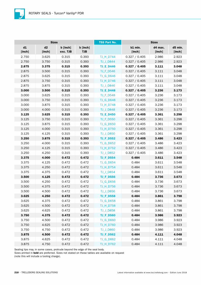
ROTARY SEALS · Turcon®Varilip®PDR
218 • TRELLEBORG SEALING SOLUTIONS Latest information available at www.tss.trelleborg.com • Edition June 2018
Sizes TSS Part No. Sizes
d1 [inch]
d2 [inch]
b [inch]exc. TJB
b [inch] TJB
b1 min. [inch]
d4 max. [inch]
d5 min. [inch]
2.750 3.625 0.315 0.393 TJ_H_D744 0.327 / 0.405 2.986 2.923
2.750 3.750 0.315 0.393 TJ_J_D844 0.327 / 0.405 2.986 2.923
2.875 3.375 0.315 0.393 TJ_E_D446 0.327 / 0.405 3.111 3.048
2.875 3.500 0.315 0.393 TJ_F_D546 0.327 / 0.405 3.111 3.048
2.875 3.625 0.315 0.393 TJ_G_D646 0.327 / 0.405 3.111 3.048
2.875 3.750 0.315 0.393 TJ_H_D746 0.327 / 0.405 3.111 3.048
2.875 3.875 0.315 0.393 TJ_J_D846 0.327 / 0.405 3.111 3.048
3.000 3.500 0.315 0.393 TJ_E_D448 0.327 / 0.405 3.236 3.173
3.000 3.625 0.315 0.393 TJ_F_D548 0.327 / 0.405 3.236 3.173
3.000 3.750 0.315 0.393 TJ_G_D648 0.327 / 0.405 3.236 3.173
3.000 3.875 0.315 0.393 TJ_H_D748 0.327 / 0.405 3.236 3.173
3.000 4.000 0.315 0.393 TJ_J_D848 0.327 / 0.405 3.236 3.173
3.125 3.625 0.315 0.393 TJ_E_D450 0.327 / 0.405 3.361 3.298
3.125 3.750 0.315 0.393 TJ_F_D550 0.327 / 0.405 3.361 3.298
3.125 3.875 0.315 0.393 TJ_G_D650 0.327 / 0.405 3.361 3.298
3.125 4.000 0.315 0.393 TJ_H_D750 0.327 / 0.405 3.361 3.298
3.125 4.125 0.315 0.393 TJ_J_D850 0.327 / 0.405 3.361 3.298
3.250 3.875 0.315 0.393 TJ_F_D552 0.327 / 0.405 3.486 3.423
3.250 4.000 0.315 0.393 TJ_G_D652 0.327 / 0.405 3.486 3.423
3.250 4.125 0.315 0.393 TJ_H_D752 0.327 / 0.405 3.486 3.423
3.250 4.250 0.315 0.393 TJ_J_D852 0.327 / 0.405 3.486 3.423
3.375 4.000 0.472 0.472 TJ_F_D554 0.484 3.611 3.548
3.375 4.125 0.472 0.472 TJ_G_D654 0.484 3.611 3.548
3.375 4.250 0.472 0.472 TJ_H_D754 0.484 3.611 3.548
3.375 4.375 0.472 0.472 TJ_J_D854 0.484 3.611 3.548
3.500 4.125 0.472 0.472 TJ_F_D556 0.484 3.736 3.673
3.500 4.250 0.472 0.472 TJ_G_D656 0.484 3.736 3.673
3.500 4.375 0.472 0.472 TJ_H_D756 0.484 3.736 3.673
3.500 4.500 0.472 0.472 TJ_J_D856 0.484 3.736 3.673
3.625 4.250 0.472 0.472 TJ_F_D558 0.484 3.861 3.798
3.625 4.375 0.472 0.472 TJ_G_D658 0.484 3.861 3.798
3.625 4.500 0.472 0.472 TJ_H_D758 0.484 3.861 3.798
3.625 4.625 0.472 0.472 TJ_J_D858 0.484 3.861 3.798
3.750 4.375 0.472 0.472 TJ_F_D560 0.484 3.986 3.923
3.750 4.500 0.472 0.472 TJ_G_D660 0.484 3.986 3.923
3.750 4.625 0.472 0.472 TJ_H_D760 0.484 3.986 3.923
3.750 4.750 0.472 0.472 TJ_J_D860 0.484 3.986 3.923
3.875 4.500 0.472 0.472 TJ_F_D562 0.484 4.111 4.048
3.875 4.625 0.472 0.472 TJ_G_D662 0.484 4.111 4.048
3.875 4.750 0.472 0.472 TJ_H_D762 0.484 4.111 4.048
Sealing lips may, in some cases, protrude beyond the edge of the seal body. Sizes printed in bold are preferred. Sizes not stated on these tables are available on request (note this will include a tooling charge).
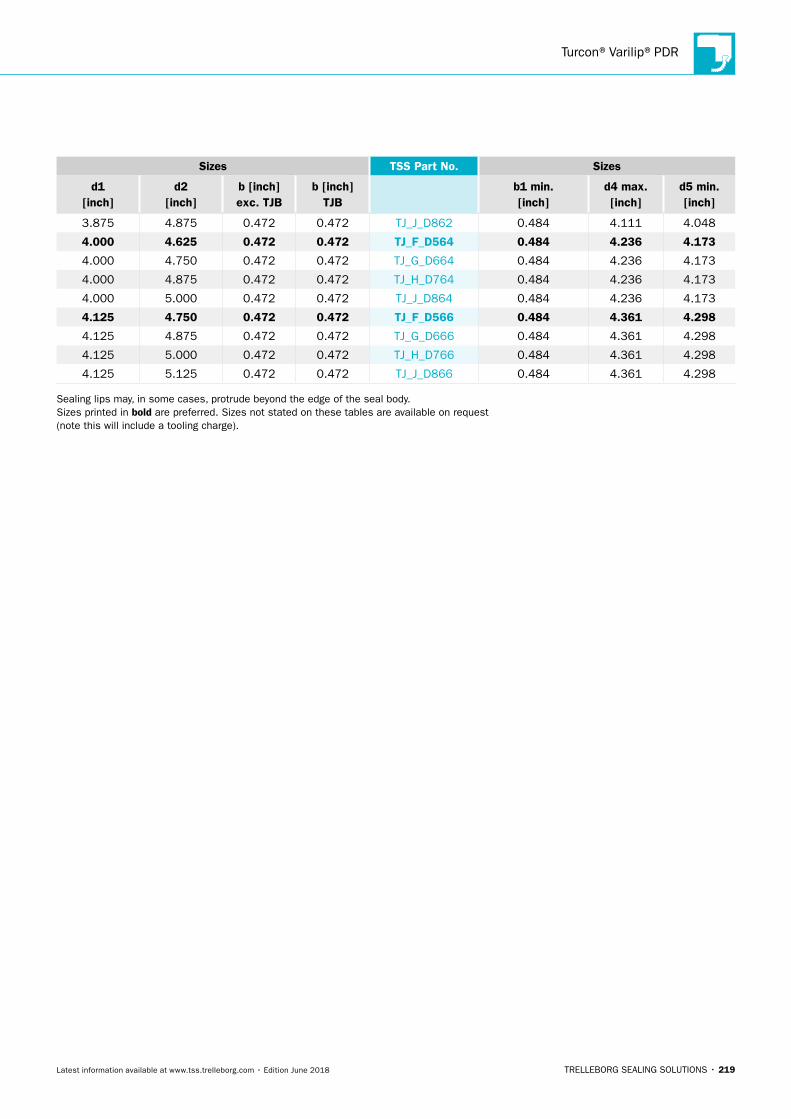
Turcon®Varilip®PDR
TRELLEBORG SEALING SOLUTIONS • 219Latest information available at www.tss.trelleborg.com • Edition June 2018
Sizes TSS Part No. Sizes
d1 [inch]
d2 [inch]
b [inch]exc. TJB
b [inch] TJB
b1 min. [inch]
d4 max. [inch]
d5 min. [inch]
3.875 4.875 0.472 0.472 TJ_J_D862 0.484 4.111 4.048
4.000 4.625 0.472 0.472 TJ_F_D564 0.484 4.236 4.173
4.000 4.750 0.472 0.472 TJ_G_D664 0.484 4.236 4.173
4.000 4.875 0.472 0.472 TJ_H_D764 0.484 4.236 4.173
4.000 5.000 0.472 0.472 TJ_J_D864 0.484 4.236 4.173
4.125 4.750 0.472 0.472 TJ_F_D566 0.484 4.361 4.298
4.125 4.875 0.472 0.472 TJ_G_D666 0.484 4.361 4.298
4.125 5.000 0.472 0.472 TJ_H_D766 0.484 4.361 4.298
4.125 5.125 0.472 0.472 TJ_J_D866 0.484 4.361 4.298
Sealing lips may, in some cases, protrude beyond the edge of the seal body. Sizes printed in bold are preferred. Sizes not stated on these tables are available on request (note this will include a tooling charge).
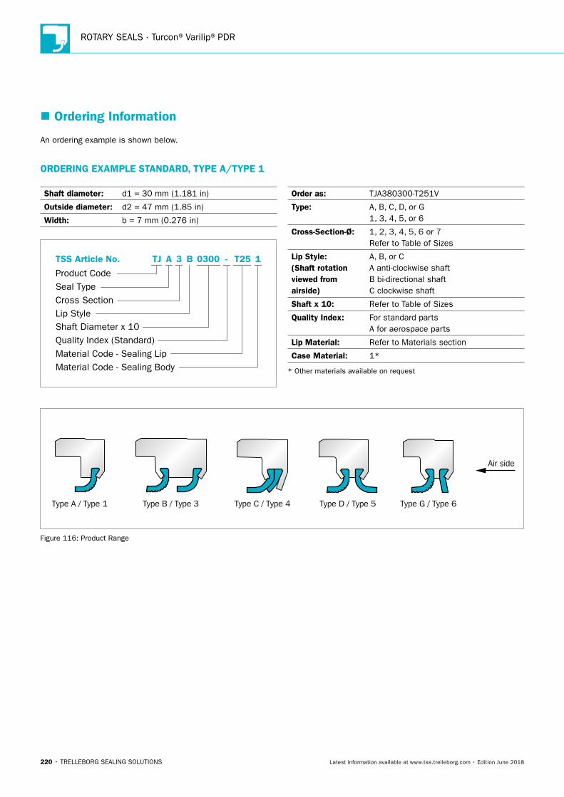
ROTARY SEALS · Turcon®Varilip®PDR
220 • TRELLEBORG SEALING SOLUTIONS Latest information available at www.tss.trelleborg.com • Edition June 2018
� Ordering Information
An ordering example is shown below.
ORDERING EXAMPLE STANDARD, TYPE A/TYPE 1
Shaft diameter : d1 = 30 mm (1.181 in)
Outside diameter: d2 = 47 mm (1.85 in)
Width: b = 7 mm (0.276 in)
Cross Section
Product Code
TSS Article No.
Seal Type
Lip Style
Quality Index (Standard)Shaft Diameter x 10
Material Code - Sealing BodyMaterial Code - Sealing Lip
TJ A 3 B 1T25-0300
Order as: TJA380300-T251V
Type: A, B, C, D, or G 1, 3, 4, 5, or 6
Cross-Section-Ø: 1, 2, 3, 4, 5, 6 or 7 Refer to Table of Sizes
Lip Style: (Shaft rotation viewed from airside)
A, B, or C A anti-clockwise shaft B bi-directional shaft C clockwise shaft
Shaft x 10: Refer to Table of Sizes
Quality Index: For standard parts A for aerospace parts
Lip Material: Refer to Materials section
Case Material: 1*
* Other materials available on request
Type A / Type 1 Type B / Type 3 Type C / Type 4 Type D / Type 5 Type G / Type 6
Air side
Figure 116: Product Range
TRELLEBORG SEALING SOLUTIONS • 221Latest information available at www.tss.trelleborg.com • Edition June 2018
Turcon®and Zurcon®Roto Seals
222 • TRELLEBORG SEALING SOLUTIONS Latest information available at www.tss.trelleborg.com • Edition June 2018
ROTARY SEALS · Turcon®and Zurcon®Roto Seals
TRELLEBORG SEALING SOLUTIONS • 223Latest information available at www.tss.trelleborg.com • Edition June 2018
Turcon®Roto Glyd Ring®

ROTARY SEALS · Turcon®Roto Glyd Ring®
224 • TRELLEBORG SEALING SOLUTIONS Latest information available at www.tss.trelleborg.com • Edition June 2018
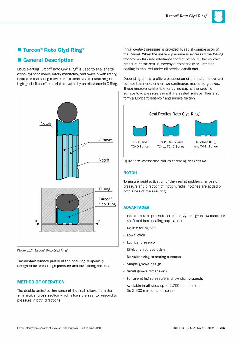
Turcon®Roto Glyd Ring®
TRELLEBORG SEALING SOLUTIONS • 225Latest information available at www.tss.trelleborg.com • Edition June 2018
� Turcon®Roto Glyd Ring®
� General DescriptionDouble-acting Turcon®Roto Glyd Ring®is used to seal shafts, axles, cylinder bores, rotary manifolds, and swivels with rotary, helical or oscillating movement. It consists of a seal ring in high-grade Turcon®material activated by an elastomeric O-Ring.
Notch
Notch
Turcon® Seal Ring
O-Ring
Grooves
PP
Figure 117: Turcon®Roto Glyd Ring®
The contact surface profile of the seal ring is specially designed for use at high-pressure and low sliding speeds.
METHOD OF OPERATION
The double acting performance of the seal follows from the symmetrical cross section which allows the seal to respond to pressure in both directions.
Initial contact pressure is provided by radial compression of the O-Ring. When the system pressure is increased the O-Ring transforms this into additional contact pressure, the contact pressure of the seal is thereby automatically adjusted so sealing is ensured under all service conditions.
Depending on the profile cross-section of the seal, the contact surface has none, one or two continuous machined grooves. These improve seal efficiency by increasing the specific surface load pressure against the sealed surface. They also form a lubricant reservoir and reduce friction.
Seal Pro�les Roto Glyd Ring®
TG30 andTG40 Series
TG31, TG32 andTG41, TG42 Series
All other TG3_ and TG4_ Series
Figure 118: Crosssection profiles depending on Series No.
NOTCH
To assure rapid activation of the seal at sudden changes of pressure and direction of motion, radial notches are added on both sides of the seal ring.
ADVANTAGES
- Initial contact pressure of Roto Glyd Ring®is available for shaft and bore sealing applications
- Double-acting seal
- Low friction
- Lubricant reservoir
- Stick-slip free operation
- No vulcanizing to mating surfaces
- Simple groove design
- Small groove dimensions
- For use at high-pressure and low sliding-speeds
- Available in all sizes up to 2.700 mm diameter (to 2.600 mm for shaft seals)
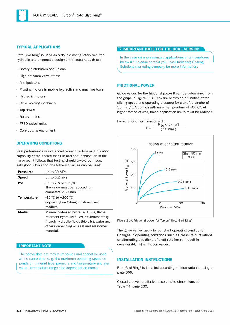
ROTARY SEALS · Turcon®Roto Glyd Ring®
226 • TRELLEBORG SEALING SOLUTIONS Latest information available at www.tss.trelleborg.com • Edition June 2018
TYPICAL APPLICATIONS
Roto Glyd Ring®is used as a double acting rotary seal for hydraulic and pneumatic equipment in sectors such as:
- Rotary distributors and unions
- High pressure valve stems
- Manipulators
- Pivoting motors in mobile hydraulics and machine tools
- Hydraulic motors
- Blow molding machines
- Top drives
- Rotary tables
- FPSO swivel units
- Core cutting equipment
OPERATING CONDITIONS
Seal performance is influenced by such factors as lubrication capability of the sealed medium and heat dissipation in the hardware. It follows that testing should always be made.With good lubrication, the following values can be used:
Pressure: Up to 30 MPa
Speed: Up to 0.2 m/s
PV: Up to 2.5 MPa m/s The value must be reduced for diameters < 50 mm.
Temperature: -45 °C to +200 °C* depending on O-Ring elastomer and medium
Media: Mineral oil-based hydraulic fluids, flame retardant hydraulic fluids, environmentally-friendly hydraulic fluids (bio-oils), water and others depending on seal and elastomer material.
IMPORTANT NOTE
The above data are maximum values and cannot be used at the same time, e. g. the maximum operating speed de-pends on material type, pressure and temperature and gap value. Temperature range also dependant on media.
*) IMPORTANT NOTE FOR THE BORE VERSION
In the case on unpressurized applications in temperatures below 0 °C please contact your local Trelleborg Sealing Solutions marketing company for more information.
FRICTIONAL POWER
Guide values for the frictional power P can be determined from the graph in Figure 119. They are shown as a function of the sliding speed and operating pressure for a shaft diameter of 50 mm / 1.968 inch with an oil temperature of +60 C°. At higher temperatures, these application limits must be reduced.
Formula for other diameters d:
P = P50 x (d) [W]
( 50 mm )Fr
ictio
nal P
ower
P5
0 (W
)
Friction at constant rotation
0
100
200
300
400
10Pressure MPa
20 30
1 m/s
0.5 m/s
0.25 m/s
0.15 m/s
Shaft 50 mm60 ºC
Figure 119: Frictional power for Turcon®Roto Glyd Ring®
The guide values apply for constant operating conditions. Changes in operating conditions such as pressure fluctuations or alternating directions of shaft rotation can result in considerably higher friction values.
INSTALLATION INSTRUCTIONS
Roto Glyd Ring®is installed according to information starting at page 309.
Closed groove installation according to dimensions at Table 74, page 230.
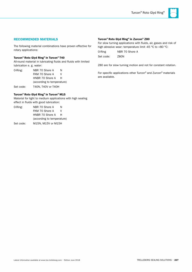
Turcon®Roto Glyd Ring®
TRELLEBORG SEALING SOLUTIONS • 227Latest information available at www.tss.trelleborg.com • Edition June 2018
RECOMMENDED MATERIALS
The following material combinations have proven effective for rotary applications:
Turcon®Roto Glyd Ring®in Turcon®T40All-round material in lubricating fluids and fluids with limited lubrication e. g. water:
O-Ring: NBR 70 Shore A N FKM 70 Shore A V HNBR 70 Shore A H (according to temperature)
Set code: T40N, T40V or T40H
Turcon®Roto Glyd Ring®in Turcon®M15Material for light to medium applications with high sealing effect in fluids with good lubrication:
O-Ring: NBR 70 Shore A N FKM 70 Shore A V HNBR 70 Shore A H (according to temperature)
Set code: M15N, M15V or M15H
Turcon®Roto Glyd Ring®in Zurcon®Z80For slow turning applications with fluids, air, gases and risk of high abrasive wear; temperature limit -45 °C to +80 °C:
O-Ring NBR 70 Shore A
Set code: Z80N
Z80 are for slow turning motion and not for constant rotation.
For specific applications other Turcon®and Zurcon®materials are available.
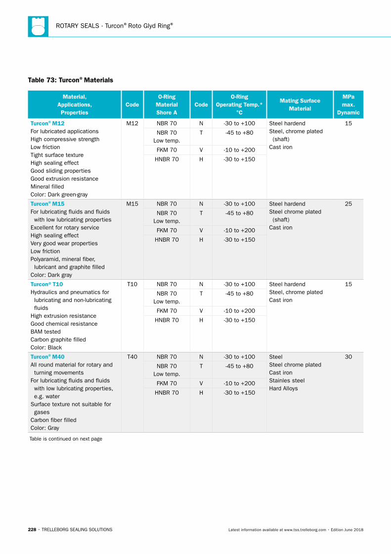
ROTARY SEALS · Turcon®Roto Glyd Ring®
228 • TRELLEBORG SEALING SOLUTIONS Latest information available at www.tss.trelleborg.com • Edition June 2018
Table 73: Turcon®Materials
Material, Applications, Properties
CodeO-Ring
Material Shore A
CodeO-Ring
Operating Temp.* °C
Mating Surface Material
MPa max.
Dynamic
Turcon®M12For lubricated applicationsHigh compressive strengthLow frictionTight surface textureHigh sealing effectGood sliding propertiesGood extrusion resistanceMineral filledColor: Dark green-gray
M12 NBR 70 N -30 to +100 Steel hardendSteel, chrome plated (shaft)Cast iron
15
NBR 70 Low temp.
T -45 to +80
FKM 70 V -10 to +200
HNBR 70 H -30 to +150
Turcon®M15For lubricating fluids and fluids with low lubricating propertiesExcellent for rotary serviceHigh sealing effectVery good wear propertiesLow frictionPolyaramid, mineral fiber, lubricant and graphite filledColor: Dark gray
M15 NBR 70 N -30 to +100 Steel hardendSteel chrome plated (shaft)Cast iron
25
NBR 70 Low temp.
T -45 to +80
FKM 70 V -10 to +200
HNBR 70 H -30 to +150
Turcon®T10Hydraulics and pneumatics for lubricating and non-lubricating fluidsHigh extrusion resistanceGood chemical resistanceBAM testedCarbon graphite filledColor: Black
T10 NBR 70 N -30 to +100 Steel hardendSteel, chrome plated Cast iron
15
NBR 70 Low temp.
T -45 to +80
FKM 70 V -10 to +200
HNBR 70 H -30 to +150
Turcon®M40All round material for rotary and turning movementsFor lubricating fluids and fluids with low lubricating properties, e.g. waterSurface texture not suitable for gasesCarbon fiber filledColor: Gray
T40 NBR 70 N -30 to +100 SteelSteel chrome platedCast ironStainles steelHard Alloys
30
NBR 70 Low temp.
T -45 to +80
FKM 70 V -10 to +200
HNBR 70 H -30 to +150
Table is continued on next page

Turcon®Roto Glyd Ring®
TRELLEBORG SEALING SOLUTIONS • 229Latest information available at www.tss.trelleborg.com • Edition June 2018
Material, Applications, Properties
CodeO-Ring
Material Shore A
CodeO-Ring
Operating Temp.* °C
Mating Surface Material
MPa max.
Dynamic
Zurcon®Z80For lubricating fluids and fluids with low lubricating properties, e.g. water, air and gases at low pressureGood abrasion resistanceGood chemical resistanceNot for contant rotationMax. working temperature +80 °CUltra high molecular weight polyethyleneColor: White to off-white
Z80 NBR 70 N -30 to +80 SteelSteel chrome platedStainles steelCeramic coating
20
FKM 70 T -10 to +80
* The O-Ring operation temperature is only valid in mineral hydraulic oil. BAM: Approved by "Bundesanstalt Materialprüfung, Germany".
Highlighted materials are recommended.
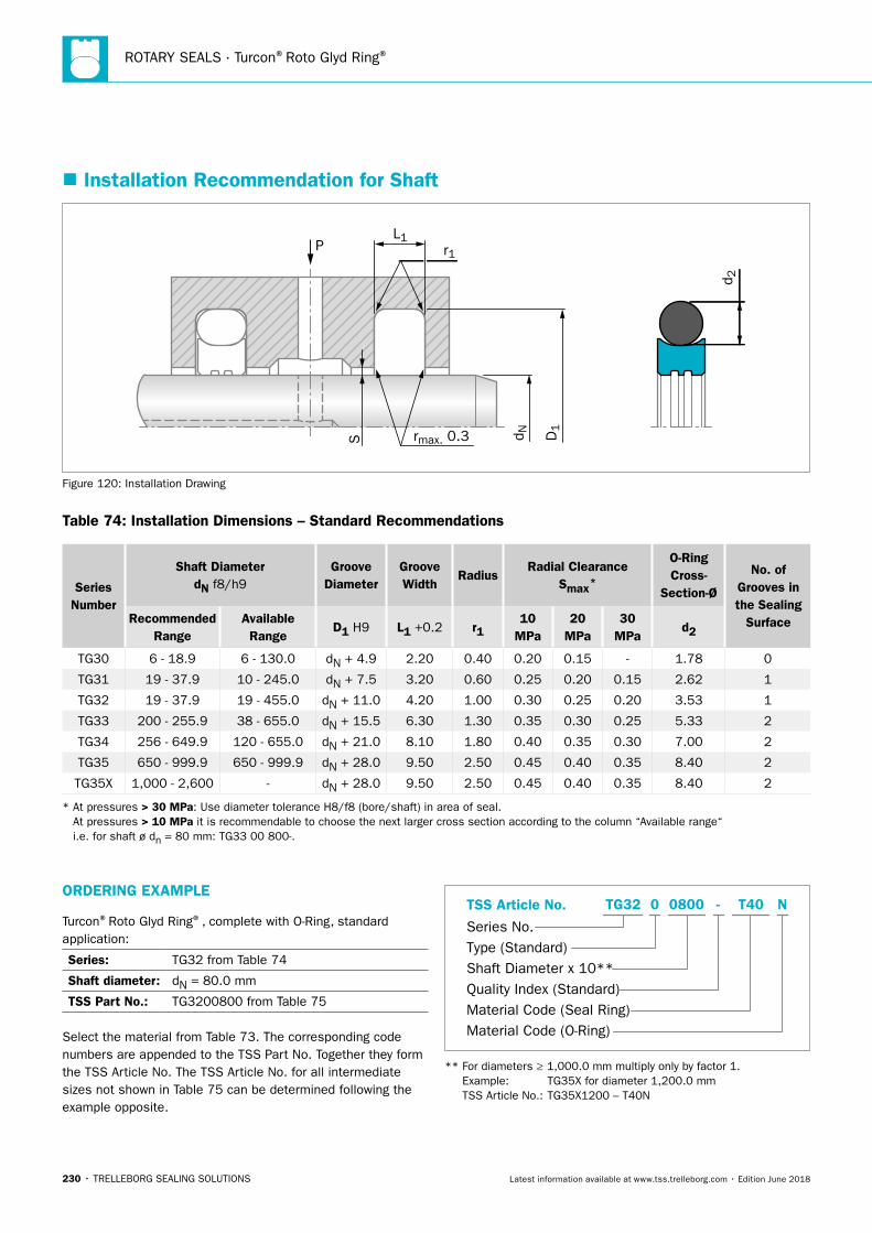
ROTARY SEALS · Turcon®Roto Glyd Ring®
230 • TRELLEBORG SEALING SOLUTIONS Latest information available at www.tss.trelleborg.com • Edition June 2018
� Installation Recommendation for Shaft
PL1
S rmax. 0.3
r1
D1
d N
d 2
Figure 120: Installation Drawing
Table 74: Installation Dimensions – Standard Recommendations
Series Number
Shaft DiameterdN f8/h9
Groove Diameter
Groove Width
RadiusRadial Clearance
Smax*
O-Ring Cross-
Section-Ø
No. of Grooves in the Sealing
SurfaceRecommended Range
Available Range
D1 H9 L1 +0.2 r110
MPa20
MPa30
MPad2
TG30 6 - 18.9 6 - 130.0 dN + 4.9 2.20 0.40 0.20 0.15 - 1.78 0
TG31 19 - 37.9 10 - 245.0 dN + 7.5 3.20 0.60 0.25 0.20 0.15 2.62 1
TG32 19 - 37.9 19 - 455.0 dN + 11.0 4.20 1.00 0.30 0.25 0.20 3.53 1
TG33 200 - 255.9 38 - 655.0 dN + 15.5 6.30 1.30 0.35 0.30 0.25 5.33 2
TG34 256 - 649.9 120 - 655.0 dN + 21.0 8.10 1.80 0.40 0.35 0.30 7.00 2
TG35 650 - 999.9 650 - 999.9 dN + 28.0 9.50 2.50 0.45 0.40 0.35 8.40 2
TG35X 1,000 - 2,600 - dN + 28.0 9.50 2.50 0.45 0.40 0.35 8.40 2
* At pressures > 30 MPa: Use diameter tolerance H8/f8 (bore/shaft) in area of seal. At pressures > 10 MPa it is recommendable to choose the next larger cross section according to the column “Available range“ i.e. for shaft ø dn = 80 mm: TG33 00 800-.
ORDERING EXAMPLE
Turcon®Roto Glyd Ring®, complete with O-Ring, standard application:
Series: TG32 from Table 74
Shaft diameter: dN = 80.0 mm
TSS Part No.: TG3200800 from Table 75
Select the material from Table 73. The corresponding code numbers are appended to the TSS Part No. Together they form the TSS Article No. The TSS Article No. for all intermediate sizes not shown in Table 75 can be determined following the example opposite.
TSS Article No.
Series No.Type (Standard)Shaft Diameter x 10**Quality Index (Standard)Material Code (Seal Ring)Material Code (O-Ring)
-TG32 0 0800 T40 N
** For diameters ≥ 1,000.0 mm multiply only by factor 1. Example: TG35X for diameter 1,200.0 mm TSS Article No.: TG35X1200 – T40N
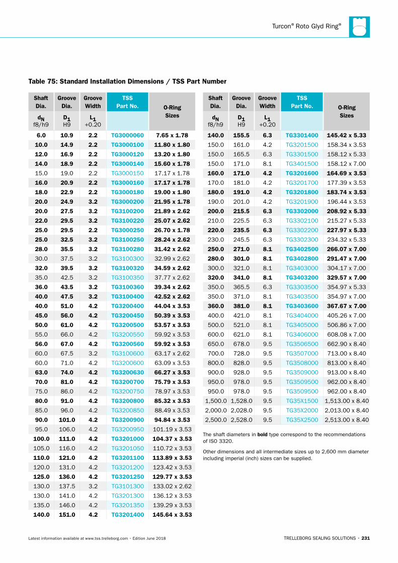
Turcon®Roto Glyd Ring®
TRELLEBORG SEALING SOLUTIONS • 231Latest information available at www.tss.trelleborg.com • Edition June 2018
Table 75: Standard Installation Dimensions / TSS Part Number
Shaft Dia.
Groove Dia.
Groove Width
TSS Part No. O-Ring
SizesdN f8/h9
D1 H9
L1 +0.20
6.0 10.9 2.2 TG3000060 7.65 x 1.78
10.0 14.9 2.2 TG3000100 11.80 x 1.80
12.0 16.9 2.2 TG3000120 13.20 x 1.80
14.0 18.9 2.2 TG3000140 15.60 x 1.78
15.0 19.0 2.2 TG3000150 17.17 x 1.78
16.0 20.9 2.2 TG3000160 17.17 x 1.78
18.0 22.9 2.2 TG3000180 19.00 x 1.80
20.0 24.9 3.2 TG3000200 21.95 x 1.78
20.0 27.5 3.2 TG3100200 21.89 x 2.62
22.0 29.5 3.2 TG3100220 25.07 x 2.62
25.0 29.5 2.2 TG3000250 26.70 x 1.78
25.0 32.5 3.2 TG3100250 28.24 x 2.62
28.0 35.5 3.2 TG3100280 31.42 x 2.62
30.0 37.5 3.2 TG3100300 32.99 x 2.62
32.0 39.5 3.2 TG3100320 34.59 x 2.62
35.0 42.5 3.2 TG3100350 37.77 x 2.62
36.0 43.5 3.2 TG3100360 39.34 x 2.62
40.0 47.5 3.2 TG3100400 42.52 x 2.62
40.0 51.0 4.2 TG3200400 44.04 x 3.53
45.0 56.0 4.2 TG3200450 50.39 x 3.53
50.0 61.0 4.2 TG3200500 53.57 x 3.53
55.0 66.0 4.2 TG3200550 59.92 x 3.53
56.0 67.0 4.2 TG3200560 59.92 x 3.53
60.0 67.5 3.2 TG3100600 63.17 x 2.62
60.0 71.0 4.2 TG3200600 63.09 x 3.53
63.0 74.0 4.2 TG3200630 66.27 x 3.53
70.0 81.0 4.2 TG3200700 75.79 x 3.53
75.0 86.0 4.2 TG3200750 78.97 x 3.53
80.0 91.0 4.2 TG3200800 85.32 x 3.53
85.0 96.0 4.2 TG3200850 88.49 x 3.53
90.0 101.0 4.2 TG3200900 94.84 x 3.53
95.0 106.0 4.2 TG3200950 101.19 x 3.53
100.0 111.0 4.2 TG3201000 104.37 x 3.53
105.0 116.0 4.2 TG3201050 110.72 x 3.53
110.0 121.0 4.2 TG3201100 113.89 x 3.53
120.0 131.0 4.2 TG3201200 123.42 x 3.53
125.0 136.0 4.2 TG3201250 129.77 x 3.53
130.0 137.5 3.2 TG3101300 133.02 x 2.62
130.0 141.0 4.2 TG3201300 136.12 x 3.53
135.0 146.0 4.2 TG3201350 139.29 x 3.53
140.0 151.0 4.2 TG3201400 145.64 x 3.53
Shaft Dia.
Groove Dia.
Groove Width
TSS Part No. O-Ring
SizesdN f8/h9
D1 H9
L1 +0.20
140.0 155.5 6.3 TG3301400 145.42 x 5.33
150.0 161.0 4.2 TG3201500 158.34 x 3.53
150.0 165.5 6.3 TG3301500 158.12 x 5.33
150.0 171.0 8.1 TG3401500 158.12 x 7.00
160.0 171.0 4.2 TG3201600 164.69 x 3.53
170.0 181.0 4.2 TG3201700 177.39 x 3.53
180.0 191.0 4.2 TG3201800 183.74 x 3.53
190.0 201.0 4.2 TG3201900 196.44 x 3.53
200.0 215.5 6.3 TG3302000 208.92 x 5.33
210.0 225.5 6.3 TG3302100 215.27 x 5.33
220.0 235.5 6.3 TG3302200 227.97 x 5.33
230.0 245.5 6.3 TG3302300 234.32 x 5.33
250.0 271.0 8.1 TG3402500 266.07 x 7.00
280.0 301.0 8.1 TG3402800 291.47 x 7.00
300.0 321.0 8.1 TG3403000 304.17 x 7.00
320.0 341.0 8.1 TG3403200 329.57 x 7.00
350.0 365.5 6.3 TG3303500 354.97 x 5.33
350.0 371.0 8.1 TG3403500 354.97 x 7.00
360.0 381.0 8.1 TG3403600 367.67 x 7.00
400.0 421.0 8.1 TG3404000 405.26 x 7.00
500.0 521.0 8.1 TG3405000 506.86 x 7.00
600.0 621.0 8.1 TG3406000 608.08 x 7.00
650.0 678.0 9.5 TG3506500 662.90 x 8.40
700.0 728.0 9.5 TG3507000 713.00 x 8.40
800.0 828.0 9.5 TG3508000 813.00 x 8.40
900.0 928.0 9.5 TG3509000 913.00 x 8.40
950.0 978.0 9.5 TG3509500 962.00 x 8.40
950.0 978.0 9.5 TG3509500 962.00 x 8.40
1,500.0 1,528.0 9.5 TG35X1500 1,513.00 x 8.40
2,000.0 2,028.0 9.5 TG35X2000 2,013.00 x 8.40
2,500.0 2,528.0 9.5 TG35X2500 2,513.00 x 8.40
The shaft diameters in bold type correspond to the recommendations of ISO 3320.
Other dimensions and all intermediate sizes up to 2,600 mm diameter including imperial (inch) sizes can be supplied.
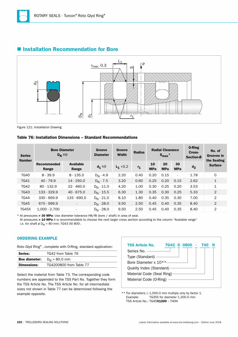
ROTARY SEALS · Turcon®Roto Glyd Ring®
232 • TRELLEBORG SEALING SOLUTIONS Latest information available at www.tss.trelleborg.com • Edition June 2018
� Installation Recommendation for Bore
P
S
L1rmax. 0.3
r1
d 2
DN
d 1
Figure 121: Installation Drawing
Table 76: Installation Dimensions – Standard Recommendations
Series Number
Bore DiameterDN H9
Groove Diameter
Groove Width
RadiusRadial Clearance
Smax*
O-Ring Cross-
Section-Ø
No. of Grooves in the Sealing
SurfaceRecommended Range
Available
Ranged1 h9 L1 +0.2 r1
10 MPa
20 MPa
30 MPa
d2
TG40 8 - 39.9 8 - 135.0 DN - 4.9 2.20 0.40 0.20 0.15 - 1.78 0
TG41 40 - 79.9 14 - 250.0 DN - 7.5 3.20 0.60 0.25 0.20 0.15 2.62 1
TG42 80 - 132.9 22 - 460.0 DN - 11.0 4.20 1.00 0.30 0.25 0.20 3.53 1
TG43 133 - 329.9 40 - 675.0 DN - 15.5 6.30 1.30 0.35 0.30 0.25 5.33 2
TG44 330 - 669.9 133 - 690.0 DN - 21.0 8.10 1.80 0.40 0.35 0.30 7.00 2
TG45 670 - 999.9 - DN - 28.0 9.50 2.50 0.45 0.40 0.35 8.40 2
TG45X 1,000 - 2,700 - DN - 28.0 9.50 2.50 0.45 0.40 0.35 8.40 2
* At pressures > 30 MPa: Use diameter tolerance H8/f8 (bore / shaft) in area of seal. At pressures > 10 MPa it is recommendable to choose the next larger cross section according to the column “Available range“ i.e. for shaft ø DN = 80 mm: TG43 00 800-.
ORDERING EXAMPLE
Roto Glyd Ring®, complete with O-Ring, standard application:
Series: TG42 from Table 76
Boe diameter: DN = 80.0 mm
Dimensions: TG4200800 from Table 77
Select the material from Table 73. The corresponding code numbers are appended to the TSS Part No. Together they form the TSS Article No. The TSS Article No. for all intermediate sizes not shown in Table 77 can be determined following the example opposite.
TSS Article No.
Series No.Type (Standard)Bore Diameter x 10**Quality Index (Standard)Material Code (Seal Ring)Material Code (O-Ring)
-TG42 0 0800 T40 N
** For diameters ≥ 1,000.0 mm multiply only by factor 1. Example: TG35X for diameter 1,200.0 mm TSS Article No.: TG45X1200 – T40N
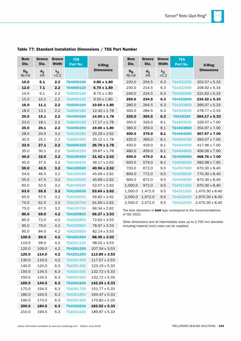
Turcon®Roto Glyd Ring®
TRELLEBORG SEALING SOLUTIONS • 233Latest information available at www.tss.trelleborg.com • Edition June 2018
Table 77: Standard Installation Dimensions / TSS Part Number
Bore Dia.
Groove Dia.
Groove Width
TSS Part No. O-Ring
DimensionsDN f8/h9
d1 H9
L1 +0.2
10.0 5.1 2.2 TG4000100 4.80 x 1.80
12.0 7.1 2.2 TG4000120 6.70 x 1.80
14.0 9.1 2.2 TG4000140 8.75 x 1.80
15.0 10.1 2.2 TG4000150 9.50 x 1.80
16.0 11.1 2.2 TG4000160 10.60 x 1.80
18.0 13.1 2.2 TG4000180 12.42 x 1.78
20.0 15.1 2.2 TG4000200 14.00 x 1.78
23.0 18.1 2.2 TG4000230 17.17 x 1.78
25.0 20.1 2.2 TG4000250 19.00 x 1.80
28.0 20.5 3.2 TG4100280 20.29 x 2.62
30.0 25.1 2.2 TG4000300 25.12 x 1.78
32.0 27.1 2.2 TG4000320 26.70 x 1.78
35.0 30.1 2.2 TG4000350 29.87 x 1.78
40.0 32.5 3.2 TG4100400 31.42 x 2.62
45.0 37.5 3.2 TG4100450 36.17 x 2.62
50.0 42.5 3.2 TG4100500 40.94 x 2.62
54.0 46.5 3.2 TG4100540 45.69 x 2.62
55.0 47.5 3.2 TG4100550 45.69 x 2.62
60.0 52.5 3.2 TG4100600 52.07 x 2.62
63.0 55.5 3.2 TG4100630 53.64 x 2.62
65.0 57.5 3.2 TG4100650 56.82 x 2.62
70.0 62.5 3.2 TG4100700 61.60 x 2.62
75.0 67.5 3.2 TG4100750 66.34 x 2.62
80.0 69.0 4.2 TG4200800 66.27 x 3.53
85.0 72.0 4.2 TG4200850 72.62 x 3.53
90.0 79.0 4.2 TG4200900 78.97 x 3.53
95.0 84.0 4.2 TG4200950 82.14 x 3.53
100.0 89.0 4.2 TG4201000 88.49 x 3.53
110.0 99.0 4.2 TG4201100 98.02 x 3.53
120.0 109.0 4.2 TG4201200 107.54 x 3.53
125.0 114.0 4.2 TG4201250 113.89 x 3.53
130.0 119.0 4.2 TG4201300 117.07 x 3.53
140.0 124.5 6.3 TG4301400 123.19 x 5.33
150.0 134.5 6.3 TG4301500 132.72 x 5.33
150.0 134.5 6.3 TG4301500 132.72 x 5.33
160.0 144.5 6.3 TG4301600 142.24 x 5.33
170.0 154.5 6.3 TG4301700 151.77 x 5.33
180.0 164.5 6.3 TG4301800 164.47 x 5.33
190.0 174.5 6.3 TG4301900 170.82 x 5.33
200.0 184.5 6.3 TG4302000 183.52 x 5.33
210.0 194.5 6.3 TG4302100 189.87 x 5.33
Bore Dia.
Groove Dia.
Groove Width
TSS Part No. O-Ring
DimensionsDN f8/h9
d1 H9
L1 +0.2
220.0 204.5 6.3 TG4302200 202.57 x 5.33
230.0 214.5 6.3 TG4302300 208.92 x 5.33
240.0 224.5 6.3 TG4302400 221.62 x 5.33
250.0 234.5 6.3 TG4302500 234.32 x 5.33
280.0 264.5 6.3 TG4302800 266.07 x 5.33
300.0 284.5 6.3 TG4303000 278.77 x 5.33
320.0 304.5 6.3 TG430320 304.17 x 5.33
350.0 329.0 8.1 TG4403500 329.57 x 7.00
380.0 359.0 8.1 TG4403800 354.97 x 7.00
400.0 379.0 8.1 TG4404000 367.67 x 7.00
420.0 399.0 8.1 TG4404200 393.07 x 7.00
450.0 429.0 8.1 TG4404500 417.96 x 7.00
480.0 459.0 8.1 TG4404800 456.06 x 7.00
500.0 479.0 8.1 TG4405000 468.76 x 7.00
600.0 579.0 8.1 TG4406000 582.68 x 7.00
700.0 672.0 9.5 TG4507000 670.30 x 8.40
800.0 772.0 9.5 TG4508000 770.30 x 8.40
900.0 872.0 9.5 TG4509000 870.30 x 8.40
1,000.0 972.0 9.5 TG45X1000 970.30 x 8.40
1,500.0 1,472.0 9.5 TG45X1500 1,470.30 x 8.40
2,000.0 1,972.0 9.5 TG45X2000 1,970.30 x 8.40
2,500.0 2,472.0 9.5 TG45X2500 2,470.30 x 8.40
The bore diameters in bold type correspond to the recommendations of ISO 3320.
Other dimensions and all intermediate sizes up to 2,700 mm diameter including imperial (inch) sizes can be supplied.

ROTARY SEALS · Turcon®Roto Glyd Ring®
234 • TRELLEBORG SEALING SOLUTIONS Latest information available at www.tss.trelleborg.com • Edition June 2018
TRELLEBORG SEALING SOLUTIONS • 235Latest information available at www.tss.trelleborg.com • Edition June 2018
Turcon®RotoGlyd Ring®K

ROTARY SEALS · Turcon®Roto Glyd Ring®K
236 • TRELLEBORG SEALING SOLUTIONS Latest information available at www.tss.trelleborg.com • Edition June 2018
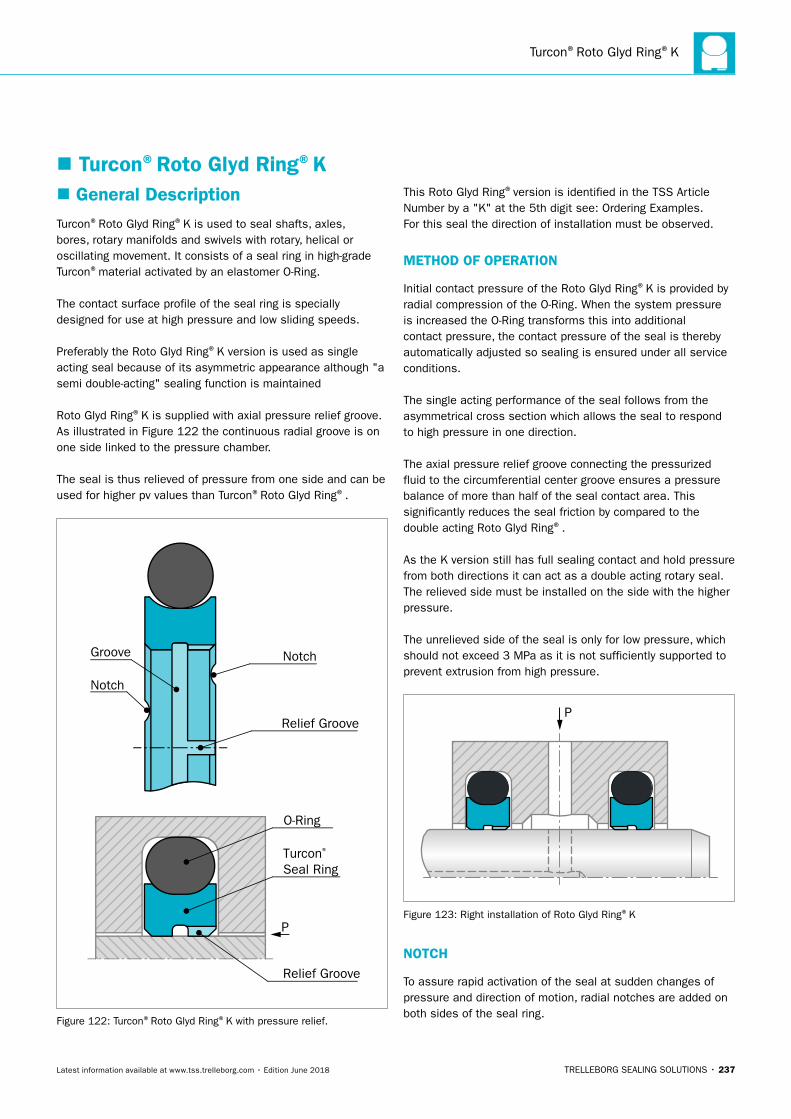
Turcon®Roto Glyd Ring®K
TRELLEBORG SEALING SOLUTIONS • 237Latest information available at www.tss.trelleborg.com • Edition June 2018
� General DescriptionTurcon®Roto Glyd Ring®K is used to seal shafts, axles, bores, rotary manifolds and swivels with rotary, helical or oscillating movement. It consists of a seal ring in high-grade Turcon®material activated by an elastomer O-Ring.
The contact surface profile of the seal ring is specially designed for use at high pressure and low sliding speeds.
Preferably the Roto Glyd Ring®K version is used as single acting seal because of its asymmetric appearance although "a semi double-acting" sealing function is maintained
Roto Glyd Ring®K is supplied with axial pressure relief groove. As illustrated in Figure 122 the continuous radial groove is on one side linked to the pressure chamber.
The seal is thus relieved of pressure from one side and can be used for higher pv values than Turcon®Roto Glyd Ring®.
Notch
Relief Groove
Turcon® Seal Ring
O-Ring
Notch
Groove
Relief Groove
P
Figure 122: Turcon®Roto Glyd Ring®K with pressure relief.
This Roto Glyd Ring®version is identified in the TSS Article Number by a "K" at the 5th digit see: Ordering Examples.For this seal the direction of installation must be observed.
METHOD OF OPERATION
Initial contact pressure of the Roto Glyd Ring®K is provided by radial compression of the O-Ring. When the system pressure is increased the O-Ring transforms this into additional contact pressure, the contact pressure of the seal is thereby automatically adjusted so sealing is ensured under all service conditions.
The single acting performance of the seal follows from the asymmetrical cross section which allows the seal to respond to high pressure in one direction.
The axial pressure relief groove connecting the pressurized fluid to the circumferential center groove ensures a pressure balance of more than half of the seal contact area. This significantly reduces the seal friction by compared to the double acting Roto Glyd Ring®.
As the K version still has full sealing contact and hold pressure from both directions it can act as a double acting rotary seal. The relieved side must be installed on the side with the higher pressure.
The unrelieved side of the seal is only for low pressure, which should not exceed 3 MPa as it is not sufficiently supported to prevent extrusion from high pressure.
P
Figure 123: Right installation of Roto Glyd Ring®K
NOTCH
To assure rapid activation of the seal at sudden changes of pressure and direction of motion, radial notches are added on both sides of the seal ring.
� Turcon®Roto Glyd Ring®K
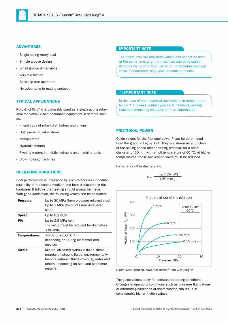
ROTARY SEALS · Turcon®Roto Glyd Ring®K
238 • TRELLEBORG SEALING SOLUTIONS Latest information available at www.tss.trelleborg.com • Edition June 2018
ADVANTAGES
- Single acting rotary seal
- Simple groove design
- Small groove dimensions
- Very low friction
- Stick-slip free operation
- No vulcanizing to mating surfaces
TYPICAL APPLICATIONS
Roto Glyd Ring®K is preferably used as a single-acting rotary seal for hydraulic and pneumatic equipment in sectors such as:
- In end caps of rotary distributors and unions
- High pressure valve stems
- Manipulators
- Hydraulic motors
- Pivoting motors in mobile hydraulic and machine tools
- Blow molding machines
OPERATING CONDITIONS
Seal performance is influenced by such factors as lubrication capability of the sealed medium and heat dissipation in the hardware. It follows that testing should always be made.With good lubrication, the following values can be assumed:
Pressure: Up to 30 MPa (from pressure relieved side) Up to 3 MPa (from pressure unrelieved side)
Speed: Up to 0.2 m/s
PV: Up to 2.5 MPa m/s The value must be reduced for diameters < 50 mm.
Temperatures: -45 °C to +200 °C *) depending on O-Ring elastomer and medium
Media: Mineral oil-based hydraulic fluids, flame- retardant hydraulic fluids, environmentally friendly hydraulic fluids (bio-oils), water and others, depending on seal and elastomer material..
IMPORTANT NOTE
The above data are maximum values and cannot be used at the same time, e. g. the maximum operating speed depends on material type, pressure, temperature and gap value. Temperature range also depends on media.
*) IMPORTANT NOTE
In the case of unpressurized applications in temperatures below 0 °C please contact your local Trelleborg Sealing Solutions marketing company for more information.
FRICTIONAL POWER
Guide values for the frictional power P can be determined from the graph in Figure 124. They are shown as a function of the sliding speed and operating pressure for a shaft diameter of 50 mm with an oil temperature of 60 °C. At higher temperatures, these application limits must be reduced.
Formula for other diameters d:
P = P50 x (d) [W]
( 50 mm )
Fric
tiona
l Pow
er P
50 (W
)
Friction at constant rotation
0
100
200
300
400
10Pressure MPa
20 30
1 m/s
0.5 m/s
0.25 m/s
0.15 m/s
Shaft 50 mm60 ºC
Figure 124: Frictional power for Turcon®Roto Glyd Ring®K
The guide values apply for constant operating conditions. Changes in operating conditions such as pressure fluctuations or alternating directions of shaft rotation can result in considerably higher friction values.
Turcon®Roto Glyd Ring®K
TRELLEBORG SEALING SOLUTIONS • 239Latest information available at www.tss.trelleborg.com • Edition June 2018
INSTALLATION INSTRUCTIONS
Roto Glyd Ring®is installed according to information at page 309.
Closed groove installation according to dimensions at Table 79 on page 242.
RECOMMENDED MATERIALS
The following material combinations have proven effective for rotary applications:
Turcon®Roto Glyd Ring®K in Turcon®T40All-round material in lubricating fluids and fluids with limited lubrication e. g. water:
O-Ring: NBR 70 Shore A N FKM 70 Shore A V HNBR 70 Shore A H (according to temperature)
Set code: T40N, T40V or T40H
Turcon®Roto Glyd Ring®K in Turcon®M15Material with high sealing effect for light to medium applications in fluids with good lubrication:
O-Ring: NBR 70 Shore A N FKM 70 Shore A V HNBR 70 Shore A H (according to temperature)
Set code: M15N, M15V or M15H
Turcon®Roto Glyd Ring®K in Zurcon®Z80For slow turning applications with fluid, air, gases and risk of high abrasive wear; temperature limit -45 °C to +80 °C:
O-Ring NBR 70 Shore A
Set code: Z80N
Z80 are for slow turning motion and not for constant rotation.
For specific applications other Turcon®and Zurcon®materials are available.
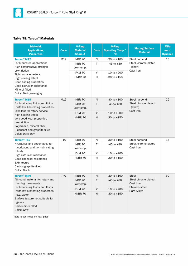
ROTARY SEALS · Turcon®Roto Glyd Ring®K
240 • TRELLEBORG SEALING SOLUTIONS Latest information available at www.tss.trelleborg.com • Edition June 2018
Table 78: Turcon®Materials
Material, Applications, Properties
CodeO-Ring
Material Shore A
CodeO-Ring
Operating Temp.* °C
Mating Surface Material
MPa max.
Dynamic
Turcon®M12For lubricated applicationsHigh compressive strengthLow frictionTight surface textureHigh sealing effectGood sliding propertiesGood extrusion resistanceMineral filledColor: Dark green-gray
M12 NBR 70 N -30 to +100 Steel hardendSteel, chrome plated (shaft)Cast iron
15
NBR 70 Low temp.
T -45 to +80
FKM 70 V -10 to +200
HNBR 70 H -30 to +150
Turcon®M15For lubricating fluids and fluids with low lubricating propertiesExcellent for rotary serviceHigh sealing effectVery good wear propertiesLow frictionPolyaramid, mineral fiber, lubricant and graphite filledColor: Dark gray
M15 NBR 70 N -30 to +100 Steel hardendSteel chrome plated (shaft)Cast iron
25
NBR 70 Low temp.
T -45 to +80
FKM 70 V -10 to +200
HNBR 70 H -30 to +150
Turcon®T10Hydraulics and pneumatics for lubricating and non-lubricating fluidsHigh extrusion resistanceGood chemical resistanceBAM testedCarbon graphite filledColor: Black
T10 NBR 70 N -30 to +100 Steel hardendSteel, chrome plated Cast iron
15
NBR 70 Low temp.
T -45 to +80
FKM 70 V -10 to +200
HNBR 70 H -30 to +150
Turcon®M40All round material for rotary and turning movementsFor lubricating fluids and fluids with low lubricating properties, e.g. waterSurface texture not suitable for gasesCarbon fiber filledColor: Gray
T40 NBR 70 N -30 to +100 SteelSteel chrome platedCast ironStainles steelHard Alloys
30
NBR 70 Low temp.
T -45 to +80
FKM 70 V -10 to +200
HNBR 70 H -30 to +150
Table is continued on next page
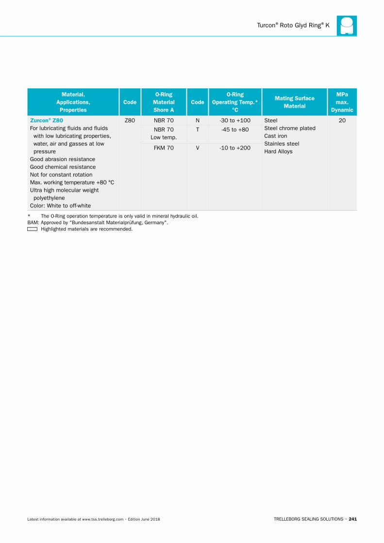
Turcon®Roto Glyd Ring®K
TRELLEBORG SEALING SOLUTIONS • 241Latest information available at www.tss.trelleborg.com • Edition June 2018
Material, Applications, Properties
CodeO-Ring
Material Shore A
CodeO-Ring
Operating Temp.* °C
Mating Surface Material
MPa max.
Dynamic
Zurcon®Z80For lubricating fluids and fluids with low lubricating properties, water, air and gasses at low pressureGood abrasion resistanceGood chemical resistanceNot for constant rotationMax. working temperature +80 °C Ultra high molecular weight polyethyleneColor: White to off-white
Z80 NBR 70 N -30 to +100 SteelSteel chrome platedCast ironStainles steelHard Alloys
20
NBR 70 Low temp.
T -45 to +80
FKM 70 V -10 to +200
* The O-Ring operation temperature is only valid in mineral hydraulic oil. BAM: Approved by "Bundesanstalt Materialprüfung, Germany".
Highlighted materials are recommended.
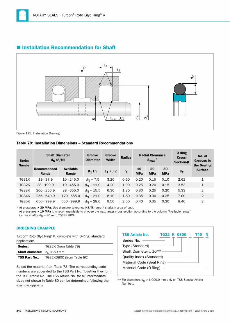
ROTARY SEALS · Turcon®Roto Glyd Ring®K
242 • TRELLEBORG SEALING SOLUTIONS Latest information available at www.tss.trelleborg.com • Edition June 2018
� Installation Recommendation for Shaft
PL1
S rmax. 0.3
r1
D1
d N
d 2
Figure 125: Installation Drawing
Table 79: Installation Dimensions – Standard Recommendations
Series Number
Shaft DiameterdN f8/h9
Groove Diameter
Groove Width
RadiusRadial Clearance
Smax*
O-Ring Cross-
Section-Ø
No. of Grooves in the Sealing
SurfaceRecommended Range
Available Range
D1 H9 L1 +0.2 r110
MPa20
MPa30
MPad2
TG31K 19 - 37.9 10 - 245.0 dN + 7.5 3.20 0.60 0.20 0.15 0.10 2.62 1
TG32K 38 - 199.9 19 - 455.0 dN + 11.0 4.20 1.00 0.25 0.20 0.15 3.53 1
TG33K 200 - 255.9 38 - 655.0 dN + 15.5 6.30 1.30 0.30 0.25 0.20 5.33 2
TG34K 256 - 649.9 120 - 655.0 dN + 21.0 8.10 1.80 0.35 0.30 0.25 7.00 2
TG35K 650 - 999.9 650 - 999.9 dN + 28.0 9.50 2.50 0.40 0.35 0.30 8.40 2
* At pressures > 30 MPa: Use diameter tolerance H8/f8 (bore / shaft) in area of seal. At pressures > 10 MPa it is recommendable to choose the next larger cross section according to the column “Available range“ i.e. for shaft ø dN = 80 mm: TG33K 800-.
ORDERING EXAMPLE
Turcon®Roto Glyd Ring®K, complete with O-Ring, standard application:
Series: TG32K (from Table 79)
Shaft diameter: dN = 80 mm
TSS Part No.: TG32K0800 (from Table 80)
Select the material from Table 78. The corresponding code numbers are appended to the TSS Part No. Together they form the TSS Article No. The TSS Article No. for all intermediate sizes not shown in Table 80 can be determined following the example opposite.
TSS Article No.
Series No.Type (Standard)Shaft Diameter x 10**Quality Index (Standard)Material Code (Seal Ring)Material Code (O-Ring)
-TG32 K 0800 T40 N
** For diameters dN ≥ 1,000.0 mm only on TSS Special Article Number..
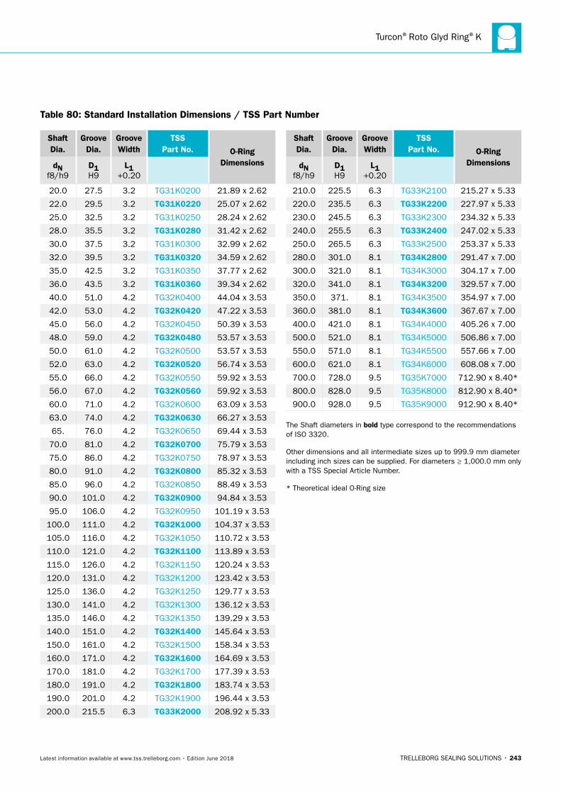
Turcon®Roto Glyd Ring®K
TRELLEBORG SEALING SOLUTIONS • 243Latest information available at www.tss.trelleborg.com • Edition June 2018
Shaft Dia.
Groove Dia.
Groove Width
TSS Part No. O-Ring
DimensionsdN f8/h9
D1 H9
L1 +0.20
20.0 27.5 3.2 TG31K0200 21.89 x 2.62
22.0 29.5 3.2 TG31K0220 25.07 x 2.62
25.0 32.5 3.2 TG31K0250 28.24 x 2.62
28.0 35.5 3.2 TG31K0280 31.42 x 2.62
30.0 37.5 3.2 TG31K0300 32.99 x 2.62
32.0 39.5 3.2 TG31K0320 34.59 x 2.62
35.0 42.5 3.2 TG31K0350 37.77 x 2.62
36.0 43.5 3.2 TG31K0360 39.34 x 2.62
40.0 51.0 4.2 TG32K0400 44.04 x 3.53
42.0 53.0 4.2 TG32K0420 47.22 x 3.53
45.0 56.0 4.2 TG32K0450 50.39 x 3.53
48.0 59.0 4.2 TG32K0480 53.57 x 3.53
50.0 61.0 4.2 TG32K0500 53.57 x 3.53
52.0 63.0 4.2 TG32K0520 56.74 x 3.53
55.0 66.0 4.2 TG32K0550 59.92 x 3.53
56.0 67.0 4.2 TG32K0560 59.92 x 3.53
60.0 71.0 4.2 TG32K0600 63.09 x 3.53
63.0 74.0 4.2 TG32K0630 66.27 x 3.53
65. 76.0 4.2 TG32K0650 69.44 x 3.53
70.0 81.0 4.2 TG32K0700 75.79 x 3.53
75.0 86.0 4.2 TG32K0750 78.97 x 3.53
80.0 91.0 4.2 TG32K0800 85.32 x 3.53
85.0 96.0 4.2 TG32K0850 88.49 x 3.53
90.0 101.0 4.2 TG32K0900 94.84 x 3.53
95.0 106.0 4.2 TG32K0950 101.19 x 3.53
100.0 111.0 4.2 TG32K1000 104.37 x 3.53
105.0 116.0 4.2 TG32K1050 110.72 x 3.53
110.0 121.0 4.2 TG32K1100 113.89 x 3.53
115.0 126.0 4.2 TG32K1150 120.24 x 3.53
120.0 131.0 4.2 TG32K1200 123.42 x 3.53
125.0 136.0 4.2 TG32K1250 129.77 x 3.53
130.0 141.0 4.2 TG32K1300 136.12 x 3.53
135.0 146.0 4.2 TG32K1350 139.29 x 3.53
140.0 151.0 4.2 TG32K1400 145.64 x 3.53
150.0 161.0 4.2 TG32K1500 158.34 x 3.53
160.0 171.0 4.2 TG32K1600 164.69 x 3.53
170.0 181.0 4.2 TG32K1700 177.39 x 3.53
180.0 191.0 4.2 TG32K1800 183.74 x 3.53
190.0 201.0 4.2 TG32K1900 196.44 x 3.53
200.0 215.5 6.3 TG33K2000 208.92 x 5.33
Shaft Dia.
Groove Dia.
Groove Width
TSS Part No. O-Ring
DimensionsdN f8/h9
D1 H9
L1 +0.20
210.0 225.5 6.3 TG33K2100 215.27 x 5.33
220.0 235.5 6.3 TG33K2200 227.97 x 5.33
230.0 245.5 6.3 TG33K2300 234.32 x 5.33
240.0 255.5 6.3 TG33K2400 247.02 x 5.33
250.0 265.5 6.3 TG33K2500 253.37 x 5.33
280.0 301.0 8.1 TG34K2800 291.47 x 7.00
300.0 321.0 8.1 TG34K3000 304.17 x 7.00
320.0 341.0 8.1 TG34K3200 329.57 x 7.00
350.0 371. 8.1 TG34K3500 354.97 x 7.00
360.0 381.0 8.1 TG34K3600 367.67 x 7.00
400.0 421.0 8.1 TG34K4000 405.26 x 7.00
500.0 521.0 8.1 TG34K5000 506.86 x 7.00
550.0 571.0 8.1 TG34K5500 557.66 x 7.00
600.0 621.0 8.1 TG34K6000 608.08 x 7.00
700.0 728.0 9.5 TG35K7000 712.90 x 8.40*
800.0 828.0 9.5 TG35K8000 812.90 x 8.40*
900.0 928.0 9.5 TG35K9000 912.90 x 8.40*
The Shaft diameters in bold type correspond to the recommendations of ISO 3320.
Other dimensions and all intermediate sizes up to 999.9 mm diameter including inch sizes can be supplied. For diameters ≥ 1,000.0 mm only with a TSS Special Article Number.
* Theoretical ideal O-Ring size
Table 80: Standard Installation Dimensions / TSS Part Number
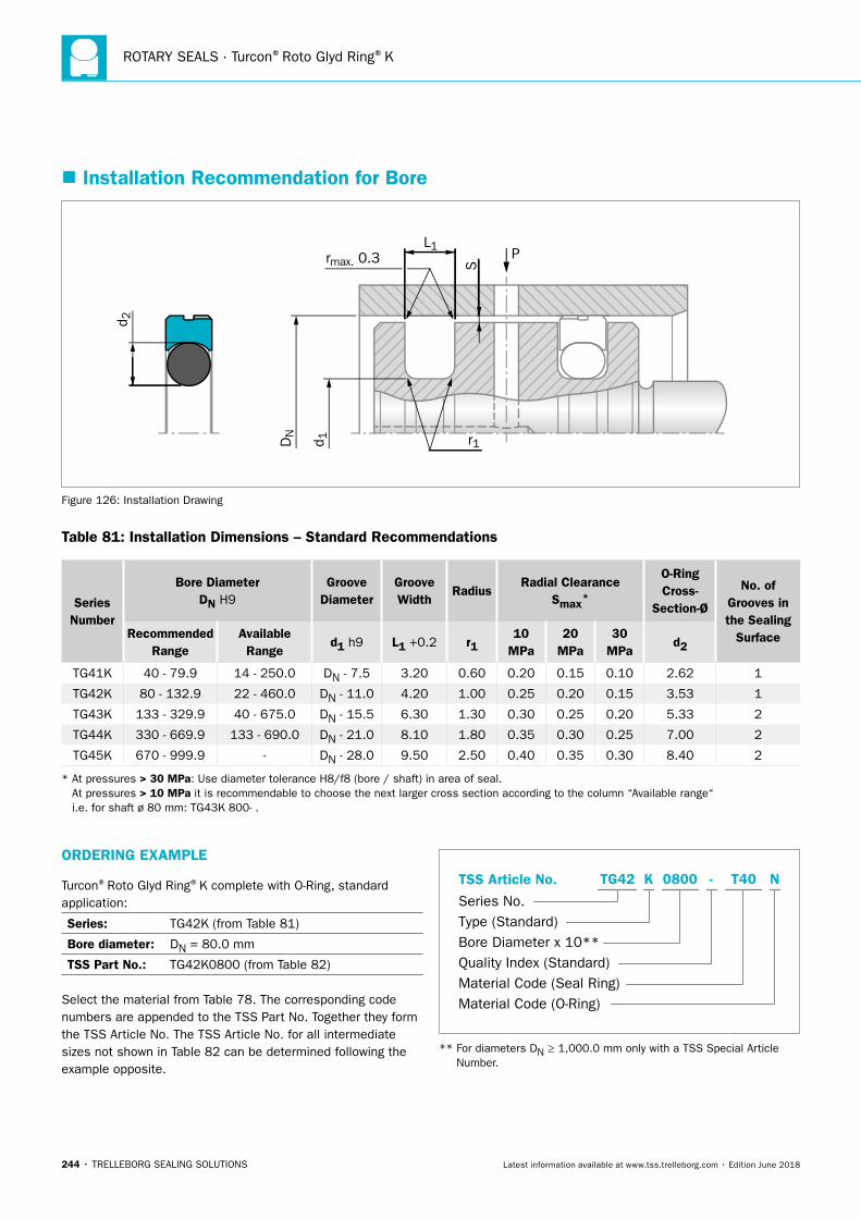
ROTARY SEALS · Turcon®Roto Glyd Ring®K
244 • TRELLEBORG SEALING SOLUTIONS Latest information available at www.tss.trelleborg.com • Edition June 2018
� Installation Recommendation for Bore
Figure 121 Installation Drawing
P
r1
S
L1rmax. 0.3
d 2
DN
d 1
Figure 126: Installation Drawing
Table 81: Installation Dimensions – Standard Recommendations
Series Number
Bore DiameterDN H9
Groove Diameter
Groove Width
RadiusRadial Clearance
Smax*
O-Ring Cross-
Section-Ø
No. of Grooves in the Sealing
SurfaceRecommended Range
Available Range
d1 h9 L1 +0.2 r110
MPa20
MPa30
MPad2
TG41K 40 - 79.9 14 - 250.0 DN - 7.5 3.20 0.60 0.20 0.15 0.10 2.62 1
TG42K 80 - 132.9 22 - 460.0 DN - 11.0 4.20 1.00 0.25 0.20 0.15 3.53 1
TG43K 133 - 329.9 40 - 675.0 DN - 15.5 6.30 1.30 0.30 0.25 0.20 5.33 2
TG44K 330 - 669.9 133 - 690.0 DN - 21.0 8.10 1.80 0.35 0.30 0.25 7.00 2
TG45K 670 - 999.9 - DN - 28.0 9.50 2.50 0.40 0.35 0.30 8.40 2
* At pressures > 30 MPa: Use diameter tolerance H8/f8 (bore / shaft) in area of seal. At pressures > 10 MPa it is recommendable to choose the next larger cross section according to the column “Available range“ i.e. for shaft ø 80 mm: TG43K 800- .
ORDERING EXAMPLE
Turcon®Roto Glyd Ring®K complete with O-Ring, standard application:
Series: TG42K (from Table 81)
Bore diameter: DN = 80.0 mm
TSS Part No.: TG42K0800 (from Table 82)
Select the material from Table 78. The corresponding code numbers are appended to the TSS Part No. Together they form the TSS Article No. The TSS Article No. for all intermediate sizes not shown in Table 82 can be determined following the example opposite.
TSS Article No.
Series No.Type (Standard)Bore Diameter x 10**Quality Index (Standard)Material Code (Seal Ring)Material Code (O-Ring)
-TG42 K 0800 T40 N
** For diameters DN ≥ 1,000.0 mm only with a TSS Special Article Number.
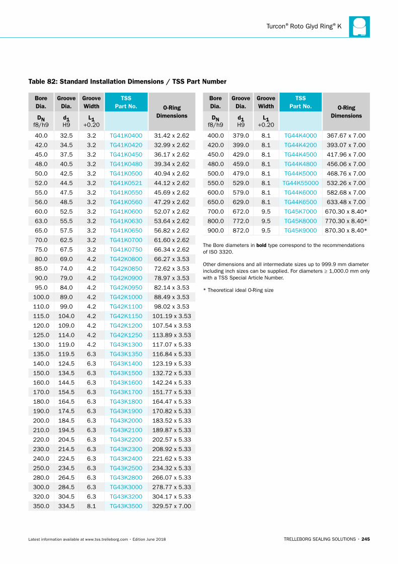
Turcon®Roto Glyd Ring®K
TRELLEBORG SEALING SOLUTIONS • 245Latest information available at www.tss.trelleborg.com • Edition June 2018
Bore Dia.
Groove Dia.
Groove Width
TSS Part No. O-Ring
DimensionsDN f8/h9
d1 H9
L1 +0.20
40.0 32.5 3.2 TG41K0400 31.42 x 2.62
42.0 34.5 3.2 TG41K0420 32.99 x 2.62
45.0 37.5 3.2 TG41K0450 36.17 x 2.62
48.0 40.5 3.2 TG41K0480 39.34 x 2.62
50.0 42.5 3.2 TG41K0500 40.94 x 2.62
52.0 44.5 3.2 TG41K0521 44.12 x 2.62
55.0 47.5 3.2 TG41K0550 45.69 x 2.62
56.0 48.5 3.2 TG41K0560 47.29 x 2.62
60.0 52.5 3.2 TG41K0600 52.07 x 2.62
63.0 55.5 3.2 TG41K0630 53.64 x 2.62
65.0 57.5 3.2 TG41K0650 56.82 x 2.62
70.0 62.5 3.2 TG41K0700 61.60 x 2.62
75.0 67.5 3.2 TG41K0750 66.34 x 2.62
80.0 69.0 4.2 TG42K0800 66.27 x 3.53
85.0 74.0 4.2 TG42K0850 72.62 x 3.53
90.0 79.0 4.2 TG42K0900 78.97 x 3.53
95.0 84.0 4.2 TG42K0950 82.14 x 3.53
100.0 89.0 4.2 TG42K1000 88.49 x 3.53
110.0 99.0 4.2 TG42K1100 98.02 x 3.53
115.0 104.0 4.2 TG42K1150 101.19 x 3.53
120.0 109.0 4.2 TG42K1200 107.54 x 3.53
125.0 114.0 4.2 TG42K1250 113.89 x 3.53
130.0 119.0 4.2 TG43K1300 117.07 x 5.33
135.0 119.5 6.3 TG43K1350 116.84 x 5.33
140.0 124.5 6.3 TG43K1400 123.19 x 5.33
150.0 134.5 6.3 TG43K1500 132.72 x 5.33
160.0 144.5 6.3 TG43K1600 142.24 x 5.33
170.0 154.5 6.3 TG43K1700 151.77 x 5.33
180.0 164.5 6.3 TG43K1800 164.47 x 5.33
190.0 174.5 6.3 TG43K1900 170.82 x 5.33
200.0 184.5 6.3 TG43K2000 183.52 x 5.33
210.0 194.5 6.3 TG43K2100 189.87 x 5.33
220.0 204.5 6.3 TG43K2200 202.57 x 5.33
230.0 214.5 6.3 TG43K2300 208.92 x 5.33
240.0 224.5 6.3 TG43K2400 221.62 x 5.33
250.0 234.5 6.3 TG43K2500 234.32 x 5.33
280.0 264.5 6.3 TG43K2800 266.07 x 5.33
300.0 284.5 6.3 TG43K3000 278.77 x 5.33
320.0 304.5 6.3 TG43K3200 304.17 x 5.33
350.0 334.5 8.1 TG43K3500 329.57 x 7.00
Bore Dia.
Groove Dia.
Groove Width
TSS Part No. O-Ring
DimensionsDN f8/h9
d1 H9
L1 +0.20
400.0 379.0 8.1 TG44K4000 367.67 x 7.00
420.0 399.0 8.1 TG44K4200 393.07 x 7.00
450.0 429.0 8.1 TG44K4500 417.96 x 7.00
480.0 459.0 8.1 TG44K4800 456.06 x 7.00
500.0 479.0 8.1 TG44K5000 468.76 x 7.00
550.0 529.0 8.1 TG44K55000 532.26 x 7.00
600.0 579.0 8.1 TG44K6000 582.68 x 7.00
650.0 629.0 8.1 TG44K6500 633.48 x 7.00
700.0 672.0 9.5 TG45K7000 670.30 x 8.40*
800.0 772.0 9.5 TG45K8000 770.30 x 8.40*
900.0 872.0 9.5 TG45K9000 870.30 x 8.40*
The Bore diameters in bold type correspond to the recommendations of ISO 3320.
Other dimensions and all intermediate sizes up to 999.9 mm diameter including inch sizes can be supplied. For diameters ≥ 1,000.0 mm only with a TSS Special Article Number.
* Theoretical ideal O-Ring size
Table 82: Standard Installation Dimensions / TSS Part Number

ROTARY SEALS · Turcon®Roto Glyd Ring®K
246 • TRELLEBORG SEALING SOLUTIONS Latest information available at www.tss.trelleborg.com • Edition June 2018
TRELLEBORG SEALING SOLUTIONS • 247Latest information available at www.tss.trelleborg.com • Edition June 2018
Turcon®Roto Glyd Ring®V

ROTARY SEALS · Turcon®Roto Glyd Ring®V
248 • TRELLEBORG SEALING SOLUTIONS Latest information available at www.tss.trelleborg.com • Edition June 2018
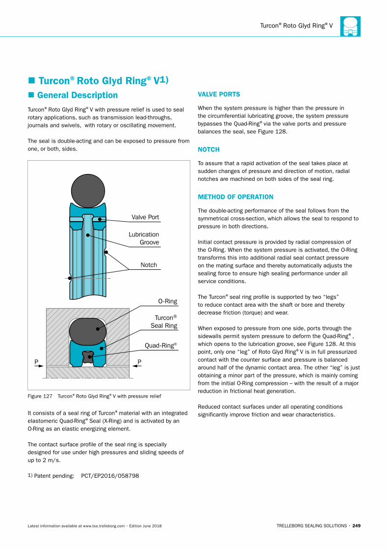
Turcon®Roto Glyd Ring®V
TRELLEBORG SEALING SOLUTIONS • 249Latest information available at www.tss.trelleborg.com • Edition June 2018
� Turcon®Roto Glyd Ring®V1)
� General DescriptionTurcon®Roto Glyd Ring®V with pressure relief is used to seal rotary applications, such as transmission lead-throughs, journals and swivels, with rotary or oscillating movement.
The seal is double-acting and can be exposed to pressure from one, or both, sides.
P P
Valve Port
LubricationGroove
Notch
O-Ring
Turcon®
Seal Ring
Quad-Ring®
Figure 127 Turcon®Roto Glyd Ring®V with pressure relief
It consists of a seal ring of Turcon®material with an integrated elastomeric Quad-Ring®Seal (X-Ring) and is activated by an O-Ring as an elastic energizing element.
The contact surface profile of the seal ring is specially designed for use under high pressures and sliding speeds of up to 2 m/s.
1) Patent pending: PCT/EP2016/058798
VALVE PORTS
When the system pressure is higher than the pressure in the circumferential lubricating groove, the system pressure bypasses the Quad-Ring®via the valve ports and pressure balances the seal, see Figure 128.
NOTCH
To assure that a rapid activation of the seal takes place at sudden changes of pressure and direction of motion, radial notches are machined on both sides of the seal ring.
METHOD OF OPERATION
The double-acting performance of the seal follows from the symmetrical cross-section, which allows the seal to respond to pressure in both directions.
Initial contact pressure is provided by radial compression of the O-Ring. When the system pressure is activated, the O-Ring transforms this into additional radial seal contact pressure on the mating surface and thereby automatically adjusts the sealing force to ensure high sealing performance under all service conditions.
The Turcon®seal ring profile is supported by two “legs” to reduce contact area with the shaft or bore and thereby decrease friction (torque) and wear.
When exposed to pressure from one side, ports through the sidewalls permit system pressure to deform the Quad-Ring®, which opens to the lubrication groove, see Figure 128. At this point, only one “leg” of Roto Glyd Ring®V is in full pressurized contact with the counter surface and pressure is balanced around half of the dynamic contact area. The other “leg” is just obtaining a minor part of the pressure, which is mainly coming from the initial O-Ring compression – with the result of a major reduction in frictional heat generation.
Reduced contact surfaces under all operating conditions significantly improve friction and wear characteristics.
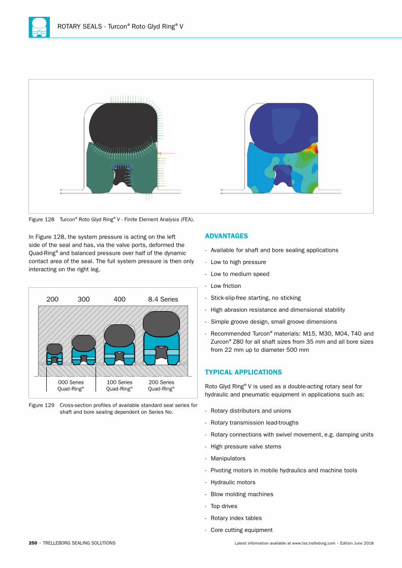
ROTARY SEALS · Turcon®Roto Glyd Ring®V
250 • TRELLEBORG SEALING SOLUTIONS Latest information available at www.tss.trelleborg.com • Edition June 2018
Figure 128 Turcon®Roto Glyd Ring®V - Finite Element Analysis (FEA).
In Figure 128, the system pressure is acting on the left side of the seal and has, via the valve ports, deformed the Quad-Ring®and balanced pressure over half of the dynamic contact area of the seal. The full system pressure is then only interacting on the right leg.
200 300 400 8.4 Series
000 SeriesQuad-Ring®
100 SeriesQuad-Ring®
200 SeriesQuad-Ring®
Figure 129 Cross-section profiles of available standard seal series for shaft and bore sealing dependent on Series No.
ADVANTAGES
- Available for shaft and bore sealing applications
- Low to high pressure
- Low to medium speed
- Low friction
- Stick-slip-free starting, no sticking
- High abrasion resistance and dimensional stability
- Simple groove design, small groove dimensions
- Recommended Turcon®materials: M15, M30, M04, T40 and Zurcon®Z80 for all shaft sizes from 35 mm and all bore sizes from 22 mm up to diameter 500 mm
TYPICAL APPLICATIONS
Roto Glyd Ring®V is used as a double-acting rotary seal for hydraulic and pneumatic equipment in applications such as:
- Rotary distributors and unions
- Rotary transmission lead-troughs
- Rotary connections with swivel movement, e.g. damping units
- High pressure valve stems
- Manipulators
- Pivoting motors in mobile hydraulics and machine tools
- Hydraulic motors
- Blow molding machines
- Top drives
- Rotary index tables
- Core cutting equipment
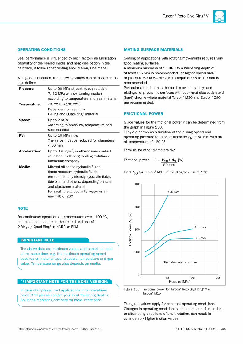
Turcon®Roto Glyd Ring®V
TRELLEBORG SEALING SOLUTIONS • 251Latest information available at www.tss.trelleborg.com • Edition June 2018
OPERATING CONDITIONS
Seal performance is influenced by such factors as lubrication capability of the sealed media and heat dissipation in the hardware, it follows that testing should always be made.
With good lubrication, the following values can be assumed as a guideline:
Pressure: Up to 20 MPa at continuous rotationTo 30 MPa at slow turning motionAccording to temperature and seal material
Temperature: -45 °C to +130 °C1)
Dependent on seal ring, O-Ring and Quad-Ring®material
Speed: Up to 2 m/sAccording to pressure, temperature and seal material
PV: Up to 10 MPa m/s The value must be reduced for diameters < 50 mm
Acceleration: Up to 0.9 m/s2, in other cases contact your local Trelleborg Sealing Solutions marketing company.
Media: Mineral oil-based hydraulic fluids, flame-retardant hydraulic fluids, environmentally friendly hydraulic fluids (bio-oils) and others, depending on seal and elastomer materialFor sealing e.g. coolants, water or air use T40 or Z80
NOTE
For continuous operation at temperatures over +100 °C, pressure and speed must be limited and use of O-Rings / Quad-Ring®in HNBR or FKM
IMPORTANT NOTE
The above data are maximum values and cannot be used at the same time, e.g. the maximum operating speed depends on material type, pressure, temperature and gap value. Temperature range also depends on media.
*) IMPORTANT NOTE FOR THE BORE VERSION:
In case of unpressurized applications in temperatures below 0 °C please contact your local Trelleborg Sealing Solutions marketing company for more information.
MATING SURFACE MATERIALS
Sealing of applications with rotating movements requires very good mating surfaces. A minimum hardness of 55 HRC to a hardening depth of at least 0.5 mm is recommended - at higher speed and/or pressure 60 to 64 HRC and a depth of 0.5 to 1.0 mm is recommended.Particular attention must be paid to avoid coatings and plating’s, e.g. ceramic surfaces with poor heat dissipation and (hard) chrome where material Turcon®M30 and Zurcon®Z80 are recommended.
FRICTIONAL POWER
Guide values for the frictional power P can be determined from the graph in Figure 130.They are shown as a function of the sliding speed and operating pressure for a shaft diameter dN of 50 mm with an oil temperature of +60 C°.
Formula for other diameters dN:
Frictional power P = P50 x dN [W] 50 mm
Find P50 for Turcon®M15 in the diagram Figure 130
0
100
200
300
400
0 10 20 30
1.0 m/s
2.0 m/s
Fric
tiona
l Pow
er P
50 (
W)
Pressure (MPa)
Shaft diameter Ø50 mm
0.6 m/s
Figure 130 Frictional power for Turcon®Roto Glyd Ring®V in Turcon®M15
The guide values apply for constant operating conditions. Changes in operating condition, such as pressure fluctuations or alternating directions of shaft rotation, can result in considerably higher friction values.
ROTARY SEALS · Turcon®Roto Glyd Ring®V
252 • TRELLEBORG SEALING SOLUTIONS Latest information available at www.tss.trelleborg.com • Edition June 2018
RECOMMENDED MATERIALS
The following material combinations have proven effective for applications with high pressure and medium rotary speed:
Roto Glyd Ring®V in Turcon®M15Standard material for Roto Glyd Ring®V.For applications where high sealing efficiency, low friction and good wear resistance are important.
O-Ring: NBR 70 Shore A N FKM 70 Shore A V (Choice of O-Ring / Quad-Ring®
depends on media and temperature)
Set code: M15N or M15V
Roto Glyd Ring®V in Turcon®M30A material that combines high sealing performance, low friction, long service life with good wear and extrusion resistance.Suitable for hard and softer mating surfaces
O-Ring: NBR 70 Shore A N FKM 70 Shore A V (Choice of O-Ring / Quad-Ring®
depends on media and temperature)
Set code: M30N or M30V
Roto Glyd Ring®V in Turcon®M04An improved carbon-filled material for linear and rotary applications which can run on softer mating surfaces.
O-Ring: NBR 70 Shore A N FKM 70 Shore A V (Choice of O-Ring / Quad-Ring®
depends on media and temperature)
Set code: M04N or M04V
Roto Glyd Ring®V in Turcon®T40Preferred for fluid applications where service life and wear resistance are more important than 100% sealing performance.For fluids with high and low lubricating properties.Preferred material for water based fluids
O-Ring: NBR 70 Shore A N FKM 70 Shore A V (Choice of O-Ring / Quad-Ring®
depends on media and temperature)
Set code: T40N or T40V
For specific applications, other material combinations are available.
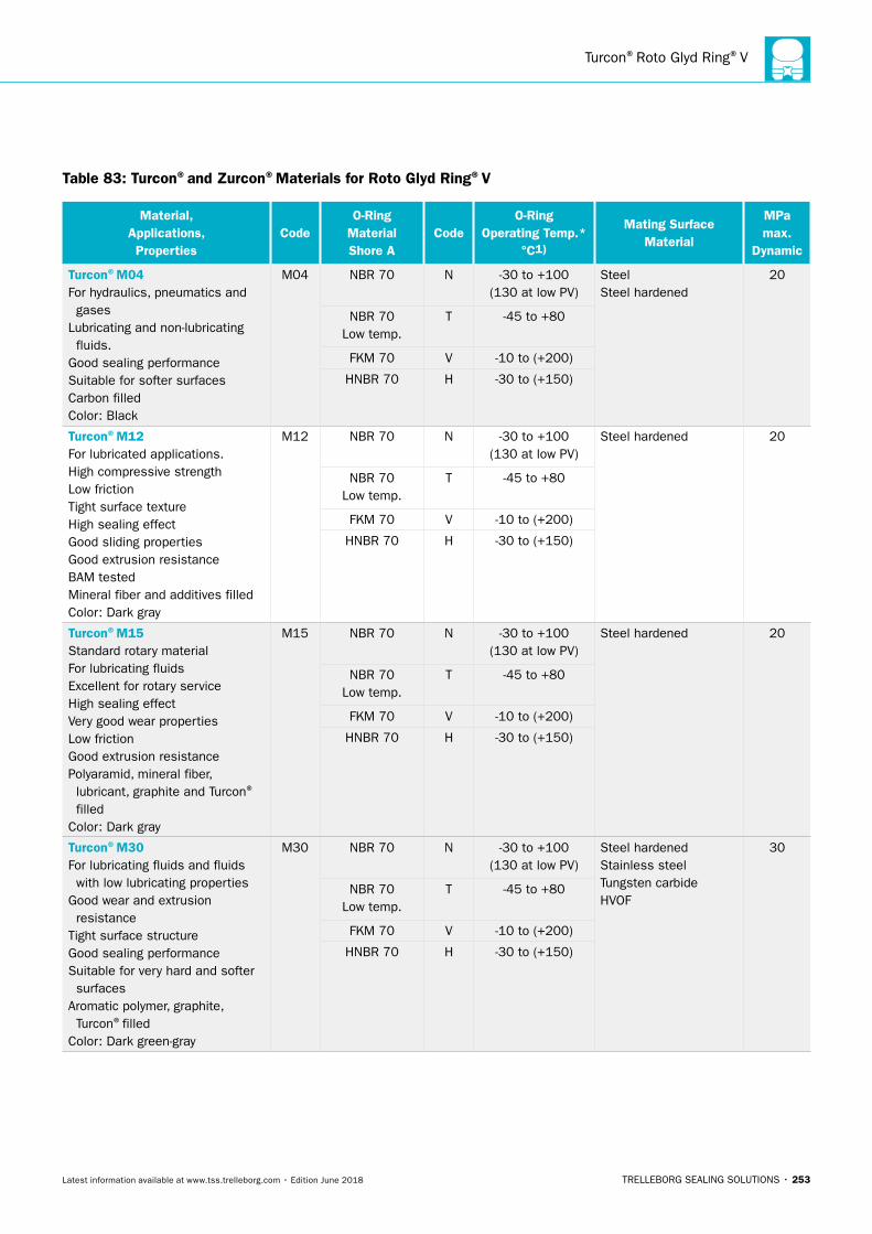
Turcon®Roto Glyd Ring®V
TRELLEBORG SEALING SOLUTIONS • 253Latest information available at www.tss.trelleborg.com • Edition June 2018
Table 83: Turcon®and Zurcon®Materials for Roto Glyd Ring®V
Material, Applications, Properties
CodeO-Ring
Material Shore A
CodeO-Ring
Operating Temp.* °C1)
Mating Surface Material
MPa max.
Dynamic
Turcon®M04For hydraulics, pneumatics and gasesLubricating and non-lubricating fluids. Good sealing performanceSuitable for softer surfacesCarbon filledColor: Black
M04 NBR 70 N -30 to +100(130 at low PV)
SteelSteel hardened
20
NBR 70 Low temp.
T -45 to +80
FKM 70 V -10 to (+200)
HNBR 70 H -30 to (+150)
Turcon®M12For lubricated applications.High compressive strengthLow frictionTight surface textureHigh sealing effectGood sliding propertiesGood extrusion resistanceBAM testedMineral fiber and additives filledColor: Dark gray
M12 NBR 70 N -30 to +100(130 at low PV)
Steel hardened 20
NBR 70 Low temp.
T -45 to +80
FKM 70 V -10 to (+200)
HNBR 70 H -30 to (+150)
Turcon®M15Standard rotary materialFor lubricating fluidsExcellent for rotary serviceHigh sealing effectVery good wear propertiesLow frictionGood extrusion resistancePolyaramid, mineral fiber, lubricant, graphite and Turcon® filledColor: Dark gray
M15 NBR 70 N -30 to +100(130 at low PV)
Steel hardened 20
NBR 70 Low temp.
T -45 to +80
FKM 70 V -10 to (+200)
HNBR 70 H -30 to (+150)
Turcon®M30For lubricating fluids and fluids with low lubricating propertiesGood wear and extrusion resistanceTight surface structureGood sealing performanceSuitable for very hard and softer surfacesAromatic polymer, graphite, Turcon®filledColor: Dark green-gray
M30 NBR 70 N -30 to +100(130 at low PV)
Steel hardenedStainless steelTungsten carbideHVOF
30
NBR 70Low temp.
T -45 to +80
FKM 70 V -10 to (+200)
HNBR 70 H -30 to (+150)
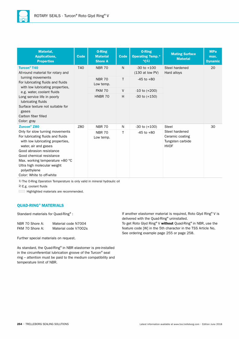
ROTARY SEALS · Turcon®Roto Glyd Ring®V
254 • TRELLEBORG SEALING SOLUTIONS Latest information available at www.tss.trelleborg.com • Edition June 2018
Material, Applications, Properties
CodeO-Ring
Material Shore A
CodeO-Ring
Operating Temp.* °C1)
Mating Surface Material
MPa max.
Dynamic
Turcon®T40All-round material for rotary and turning movementsFor lubricating fluids and fluids with low lubricating properties, e.g. water, coolant fluidsLong service life in poorly lubricating fluidsSurface texture not suitable for gasesCarbon fiber filledColor: gray
T40 NBR 70 N -30 to +100(130 at low PV)
Steel hardenedHard alloys
20
NBR 70Low temp.
T -45 to +80
FKM 70 V -10 to (+200)
HNBR 70 H -30 to (+150)
Zurcon®Z80Only for slow turning movementsFor lubricating fluids and fluids with low lubricating properties, water, air and gasesGood abrasion resistanceGood chemical resistanceMax. working temperature +80 °CUltra high molecular weight polyethyleneColor: White to off-white
Z80 NBR 70 N -30 to (+100) SteelSteel hardenedCeramic coatingTungsten carbideHVOF
30
NBR 70Low temp.
T -45 to +80
1) The O-Ring Operation Temperature is only valid in mineral hydraulic oil2) E.g. coolant fluids
Highlighted materials are recommended.
QUAD-RING®MATERIALS
Standard materials for Quad-Ring®:
NBR 70 Shore A: Material code N7004FKM 70 Shore A: Material code V7002s
Further special materials on request.
As standard, the Quad-Ring®in NBR elastomer is pre-installed in the circumferential lubrication groove of the Turcon®seal ring – attention must be paid to the medium compatibility and temperature limit of NBR.
If another elastomer material is required, Roto Glyd Ring®V is delivered with the Quad-Ring®uninstalled.To get Roto Glyd Ring®V without Quad-Ring®in NBR, use the feature code [W] in the 5th character in the TSS Article No, See ordering example page 255 or page 258.
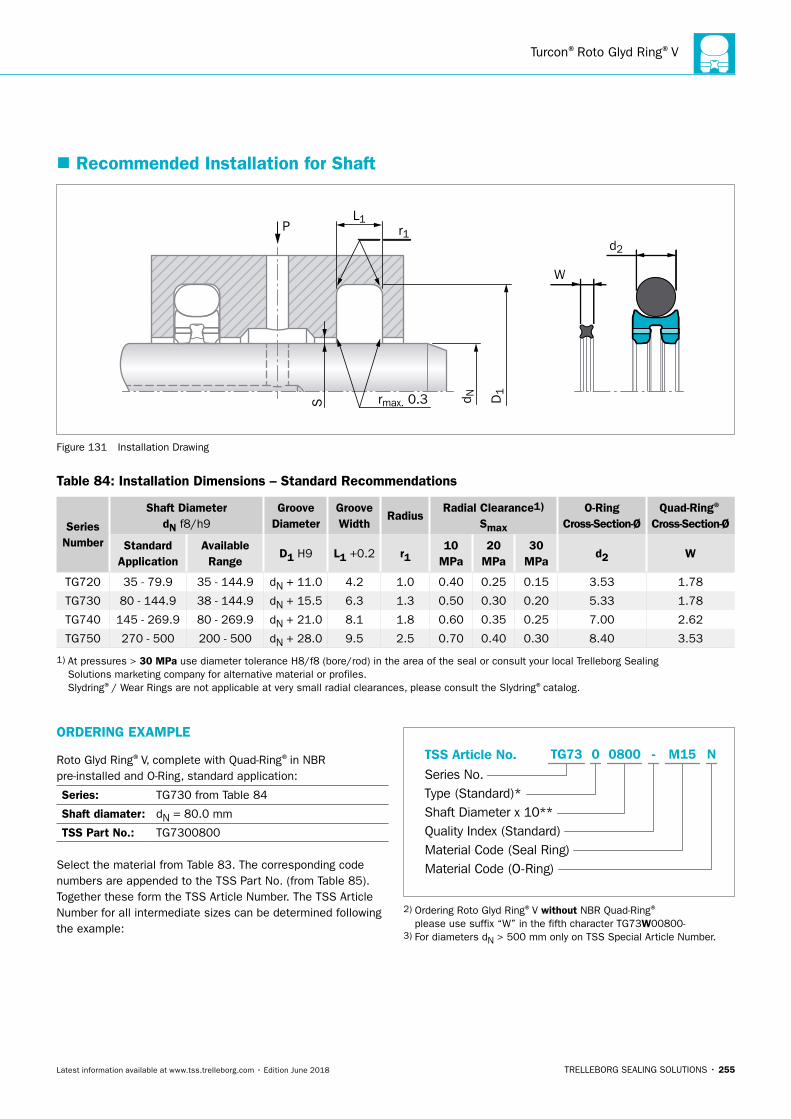
Turcon®Roto Glyd Ring®V
TRELLEBORG SEALING SOLUTIONS • 255Latest information available at www.tss.trelleborg.com • Edition June 2018
ORDERING EXAMPLE
Roto Glyd Ring®V, complete with Quad-Ring®in NBR pre-installed and O-Ring, standard application:
Series: TG730 from Table 84
Shaft diamater: dN = 80.0 mm
TSS Part No.: TG7300800
Select the material from Table 83. The corresponding code numbers are appended to the TSS Part No. (from Table 85). Together these form the TSS Article Number. The TSS Article Number for all intermediate sizes can be determined following the example:
TSS Article No.Series No.Type (Standard)*Shaft Diameter x 10**Quality Index (Standard)Material Code (Seal Ring)Material Code (O-Ring)
-TG73 0 0800 M15 N
2) Ordering Roto Glyd Ring®V without NBR Quad-Ring® please use suffix “W” in the fifth character TG73W00800- 3) For diameters dN > 500 mm only on TSS Special Article Number.
� Recommended Installation for Shaft
PL1
S rmax. 0.3
r1
D1
d N
d2
W
Figure 131 Installation Drawing
Table 84: Installation Dimensions – Standard Recommendations
Series Number
Shaft DiameterdN f8/h9
Groove Diameter
Groove Width
RadiusRadial Clearance1)
Smax
O-Ring Cross-Section-Ø
Quad-Ring®
Cross-Section-Ø
Standard Application
Available Range
D1 H9 L1 +0.2 r110
MPa20
MPa30
MPad2 W
TG720 35 - 79.9 35 - 144.9 dN + 11.0 4.2 1.0 0.40 0.25 0.15 3.53 1.78
TG730 80 - 144.9 38 - 144.9 dN + 15.5 6.3 1.3 0.50 0.30 0.20 5.33 1.78
TG740 145 - 269.9 80 - 269.9 dN + 21.0 8.1 1.8 0.60 0.35 0.25 7.00 2.62
TG750 270 - 500 200 - 500 dN + 28.0 9.5 2.5 0.70 0.40 0.30 8.40 3.53
1) At pressures > 30 MPa use diameter tolerance H8/f8 (bore/rod) in the area of the seal or consult your local Trelleborg Sealing Solutions marketing company for alternative material or profiles. Slydring®/ Wear Rings are not applicable at very small radial clearances, please consult the Slydring®catalog.
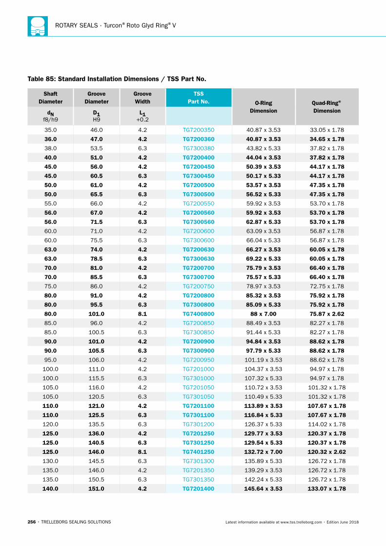
ROTARY SEALS · Turcon®Roto Glyd Ring®V
256 • TRELLEBORG SEALING SOLUTIONS Latest information available at www.tss.trelleborg.com • Edition June 2018
Shaft Diameter
Groove Diameter
Groove Width
TSS Part No. O-Ring
DimensionQuad-Ring®
DimensiondN f8/h9
D1 H9
L1 +0.2
35.0 46.0 4.2 TG7200350 40.87 x 3.53 33.05 x 1.78
36.0 47.0 4.2 TG7200360 40.87 x 3.53 34.65 x 1.78
38.0 53.5 6.3 TG7300380 43.82 x 5.33 37.82 x 1.78
40.0 51.0 4.2 TG7200400 44.04 x 3.53 37.82 x 1.78
45.0 56.0 4.2 TG7200450 50.39 x 3.53 44.17 x 1.78
45.0 60.5 6.3 TG7300450 50.17 x 5.33 44.17 x 1.78
50.0 61.0 4.2 TG7200500 53.57 x 3.53 47.35 x 1.78
50.0 65.5 6.3 TG7300500 56.52 x 5.33 47.35 x 1.78
55.0 66.0 4.2 TG7200550 59.92 x 3.53 53.70 x 1.78
56.0 67.0 4.2 TG7200560 59.92 x 3.53 53.70 x 1.78
56.0 71.5 6.3 TG7300560 62.87 x 5.33 53.70 x 1.78
60.0 71.0 4.2 TG7200600 63.09 x 3.53 56.87 x 1.78
60.0 75.5 6.3 TG7300600 66.04 x 5.33 56.87 x 1.78
63.0 74.0 4.2 TG7200630 66.27 x 3.53 60.05 x 1.78
63.0 78.5 6.3 TG7300630 69.22 x 5.33 60.05 x 1.78
70.0 81.0 4.2 TG7200700 75.79 x 3.53 66.40 x 1.78
70.0 85.5 6.3 TG7300700 75.57 x 5.33 66.40 x 1.78
75.0 86.0 4.2 TG7200750 78.97 x 3.53 72.75 x 1.78
80.0 91.0 4.2 TG7200800 85.32 x 3.53 75.92 x 1.78
80.0 95.5 6.3 TG7300800 85.09 x 5.33 75.92 x 1.78
80.0 101.0 8.1 TG7400800 88 x 7.00 75.87 x 2.62
85.0 96.0 4.2 TG7200850 88.49 x 3.53 82.27 x 1.78
85.0 100.5 6.3 TG7300850 91.44 x 5.33 82.27 x 1.78
90.0 101.0 4.2 TG7200900 94.84 x 3.53 88.62 x 1.78
90.0 105.5 6.3 TG7300900 97.79 x 5.33 88.62 x 1.78
95.0 106.0 4.2 TG7200950 101.19 x 3.53 88.62 x 1.78
100.0 111.0 4.2 TG7201000 104.37 x 3.53 94.97 x 1.78
100.0 115.5 6.3 TG7301000 107.32 x 5.33 94.97 x 1.78
105.0 116.0 4.2 TG7201050 110.72 x 3.53 101.32 x 1.78
105.0 120.5 6.3 TG7301050 110.49 x 5.33 101.32 x 1.78
110.0 121.0 4.2 TG7201100 113.89 x 3.53 107.67 x 1.78
110.0 125.5 6.3 TG7301100 116.84 x 5.33 107.67 x 1.78
120.0 135.5 6.3 TG7301200 126.37 x 5.33 114.02 x 1.78
125.0 136.0 4.2 TG7201250 129.77 x 3.53 120.37 x 1.78
125.0 140.5 6.3 TG7301250 129.54 x 5.33 120.37 x 1.78
125.0 146.0 8.1 TG7401250 132.72 x 7.00 120.32 x 2.62
130.0 145.5 6.3 TG7301300 135.89 x 5.33 126.72 x 1.78
135.0 146.0 4.2 TG7201350 139.29 x 3.53 126.72 x 1.78
135.0 150.5 6.3 TG7301350 142.24 x 5.33 126.72 x 1.78
140.0 151.0 4.2 TG7201400 145.64 x 3.53 133.07 x 1.78
Table 85: Standard Installation Dimensions / TSS Part No.
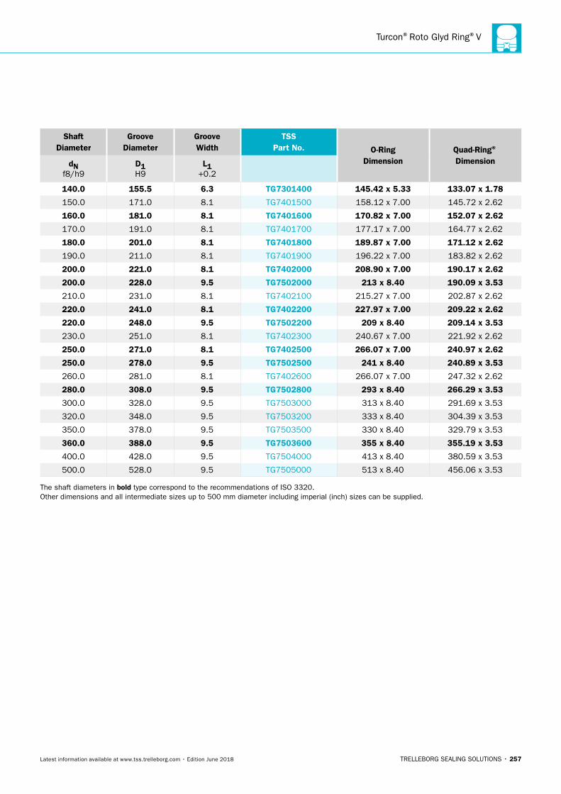
Turcon®Roto Glyd Ring®V
TRELLEBORG SEALING SOLUTIONS • 257Latest information available at www.tss.trelleborg.com • Edition June 2018
Shaft Diameter
Groove Diameter
Groove Width
TSS Part No. O-Ring
DimensionQuad-Ring®
DimensiondN f8/h9
D1 H9
L1 +0.2
140.0 155.5 6.3 TG7301400 145.42 x 5.33 133.07 x 1.78
150.0 171.0 8.1 TG7401500 158.12 x 7.00 145.72 x 2.62
160.0 181.0 8.1 TG7401600 170.82 x 7.00 152.07 x 2.62
170.0 191.0 8.1 TG7401700 177.17 x 7.00 164.77 x 2.62
180.0 201.0 8.1 TG7401800 189.87 x 7.00 171.12 x 2.62
190.0 211.0 8.1 TG7401900 196.22 x 7.00 183.82 x 2.62
200.0 221.0 8.1 TG7402000 208.90 x 7.00 190.17 x 2.62
200.0 228.0 9.5 TG7502000 213 x 8.40 190.09 x 3.53
210.0 231.0 8.1 TG7402100 215.27 x 7.00 202.87 x 2.62
220.0 241.0 8.1 TG7402200 227.97 x 7.00 209.22 x 2.62
220.0 248.0 9.5 TG7502200 209 x 8.40 209.14 x 3.53
230.0 251.0 8.1 TG7402300 240.67 x 7.00 221.92 x 2.62
250.0 271.0 8.1 TG7402500 266.07 x 7.00 240.97 x 2.62
250.0 278.0 9.5 TG7502500 241 x 8.40 240.89 x 3.53
260.0 281.0 8.1 TG7402600 266.07 x 7.00 247.32 x 2.62
280.0 308.0 9.5 TG7502800 293 x 8.40 266.29 x 3.53
300.0 328.0 9.5 TG7503000 313 x 8.40 291.69 x 3.53
320.0 348.0 9.5 TG7503200 333 x 8.40 304.39 x 3.53
350.0 378.0 9.5 TG7503500 330 x 8.40 329.79 x 3.53
360.0 388.0 9.5 TG7503600 355 x 8.40 355.19 x 3.53
400.0 428.0 9.5 TG7504000 413 x 8.40 380.59 x 3.53
500.0 528.0 9.5 TG7505000 513 x 8.40 456.06 x 3.53
The shaft diameters in bold type correspond to the recommendations of ISO 3320. Other dimensions and all intermediate sizes up to 500 mm diameter including imperial (inch) sizes can be supplied.
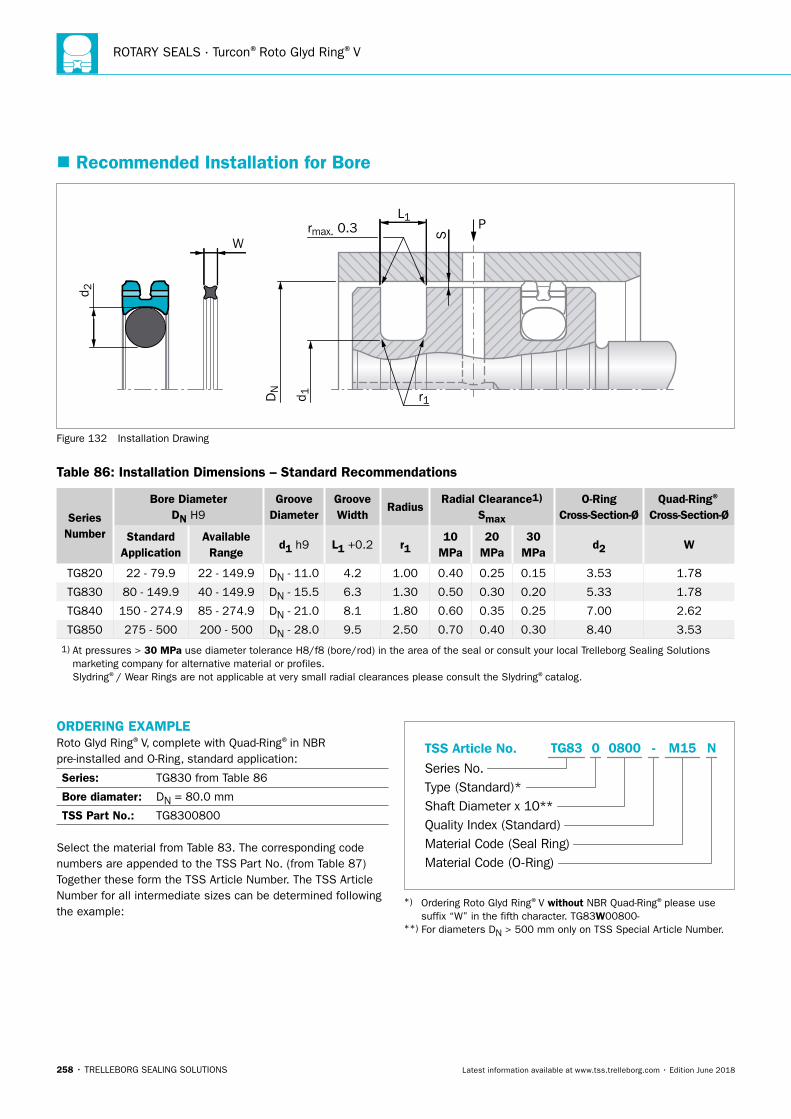
ROTARY SEALS · Turcon®Roto Glyd Ring®V
258 • TRELLEBORG SEALING SOLUTIONS Latest information available at www.tss.trelleborg.com • Edition June 2018
� Recommended Installation for Bore
P
d 2
S
L1rmax. 0.3
r1DN
d 1
W
Figure 132 Installation Drawing
Table 86: Installation Dimensions – Standard Recommendations
Series Number
Bore DiameterDN H9
Groove Diameter
Groove Width
RadiusRadial Clearance1)
Smax
O-Ring Cross-Section-Ø
Quad-Ring® Cross-Section-Ø
Standard Application
Available Range
d1 h9 L1 +0.2 r110
MPa20
MPa30
MPad2 W
TG820 22 - 79.9 22 - 149.9 DN - 11.0 4.2 1.00 0.40 0.25 0.15 3.53 1.78
TG830 80 - 149.9 40 - 149.9 DN - 15.5 6.3 1.30 0.50 0.30 0.20 5.33 1.78
TG840 150 - 274.9 85 - 274.9 DN - 21.0 8.1 1.80 0.60 0.35 0.25 7.00 2.62
TG850 275 - 500 200 - 500 DN - 28.0 9.5 2.50 0.70 0.40 0.30 8.40 3.53
1) At pressures > 30 MPa use diameter tolerance H8/f8 (bore/rod) in the area of the seal or consult your local Trelleborg Sealing Solutions marketing company for alternative material or profiles. Slydring®/ Wear Rings are not applicable at very small radial clearances please consult the Slydring®catalog.
ORDERING EXAMPLERoto Glyd Ring®V, complete with Quad-Ring®in NBR pre-installed and O-Ring, standard application:
Series: TG830 from Table 86
Bore diamater: DN = 80.0 mm
TSS Part No.: TG8300800
Select the material from Table 83. The corresponding code numbers are appended to the TSS Part No. (from Table 87) Together these form the TSS Article Number. The TSS Article Number for all intermediate sizes can be determined following the example:
TSS Article No.Series No.Type (Standard)*Shaft Diameter x 10**Quality Index (Standard)Material Code (Seal Ring)Material Code (O-Ring)
-TG83 0 0800 M15 N
*) Ordering Roto Glyd Ring®V without NBR Quad-Ring®please use suffix “W” in the fifth character. TG83W00800- **) For diameters DN > 500 mm only on TSS Special Article Number.
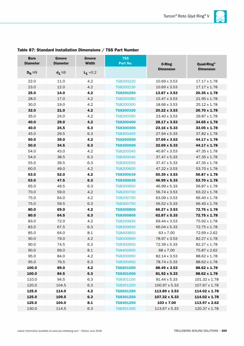
Turcon®Roto Glyd Ring®V
TRELLEBORG SEALING SOLUTIONS • 259Latest information available at www.tss.trelleborg.com • Edition June 2018
Table 87: Standard Installation Dimensions / TSS Part Number
BoreDiameter
Groove Diameter
Groove Width
TSS Part No. O-Ring
DimensionQuad-Ring®
DimensionDN H9 d1 h9 L1 +0.2
22.0 11.0 4.2 TG8200220 10.69 x 3.53 17.17 x 1.78
23.0 12.0 4.2 TG8200230 10.69 x 3.53 17.17 x 1.78
25.0 14.0 4.2 TG8200250 13.87 x 3.53 20.35 x 1.78
28.0 17.0 4.2 TG8200280 15.47 x 3.53 21.95 x 1.78
30.0 19.0 4.2 TG8200300 18.66 x 3.53 25.12 x 1.78
32.0 21.0 4.2 TG8200320 20.22 x 3.53 26.70 x 1.78
35.0 24.0 4.2 TG8200350 23.40 x 3.53 29.87 x 1.78
40.0 29.0 4.2 TG8200400 28.17 x 3.53 34.65 x 1.78
40.0 24.5 6.3 TG8300400 23.16 x 5.33 33.05 x 1.78
45.0 29.5 6.3 TG8300450 27.94 x 5.33 37.82 x 1.78
50.0 39.0 4.2 TG8200500 37.69 x 3.53 44.17 x 1.78
50.0 34.5 6.3 TG8300500 32.69 x 5.33 44.17 x 1.78
54.0 43.0 4.2 TG8200540 40.87 x 3.53 47.35 x 1.78
54.0 38.5 6.3 TG8300540 37.47 x 5.33 47.35 x 1.78
55.0 39.5 6.3 TG8300550 37.47 x 5.33 47.35 x 1.78
60.0 49.0 4.2 TG8200600 47.22 x 3.53 53.70 x 1.78
63.0 52.0 4.2 TG8200630 50.39 x 3.53 56.87 x 1.78
63.0 47.5 6.3 TG8300630 46.99 x 5.33 53.70 x 1.78
65.0 49.5 6.3 TG8300650 46.99 x 5.33 56.87 x 1.78
70.0 59.0 4.2 TG8200700 56.74 x 3.53 63.22 x 1.78
75.0 64.0 4.2 TG8200750 63.09 x 3.53 66.40 x 1.78
75.0 59.5 6.3 TG8300750 56.52 x 5.33 66.40 x 1.78
80.0 69.0 4.2 TG8200800 66.27 x 3.53 72.75 x 1.78
80.0 64.5 6.3 TG8300800 62.87 x 5.33 72.75 x 1.78
83.0 72.0 4.2 TG8200830 69.44 x 3.53 75.92 x 1.78
83.0 67.5 6.3 TG8300830 66.04 x 5.33 72.75 x 1.78
85.0 64.0 8.1 TG8400850 63 x 7.00 72.69 x 2.62
90.0 79.0 4.2 TG8200900 78.97 x 3.53 82.27 x 1.78
90.0 74.5 6.3 TG8300900 72.39 x 5.33 82.27 x 1.78
90.0 69.0 8.1 TG8400900 68 x 7.00 75.87 x 2.62
95.0 84.0 4.2 TG8200950 82.14 x 3.53 88.62 x 1.78
95.0 79.5 6.3 TG8300950 78.74 x 5.33 88.62 x 1.78
100.0 89.0 4.2 TG8201000 88.49 x 3.53 88.62 x 1.78
100.0 84.5 6.3 TG8301000 81.92 x 5.33 88.62 x 1.78
110.0 94.5 6.3 TG8301100 91.44 x 5.33 101.32 x 1.78
120.0 104.5 6.3 TG8301200 100.97 x 5.33 107.67 x 1.78
125.0 114.0 4.2 TG8201250 113.89 x 3.53 114.02 x 1.78
125.0 109.5 6.3 TG8301250 107.32 x 5.33 114.02 x 1.78
125.0 104.0 8.1 TG8401250 103 x 7.00 113.97 x 2.62
130.0 114.5 6.3 TG8301300 113.67 x 5.33 120.37 x 1.78
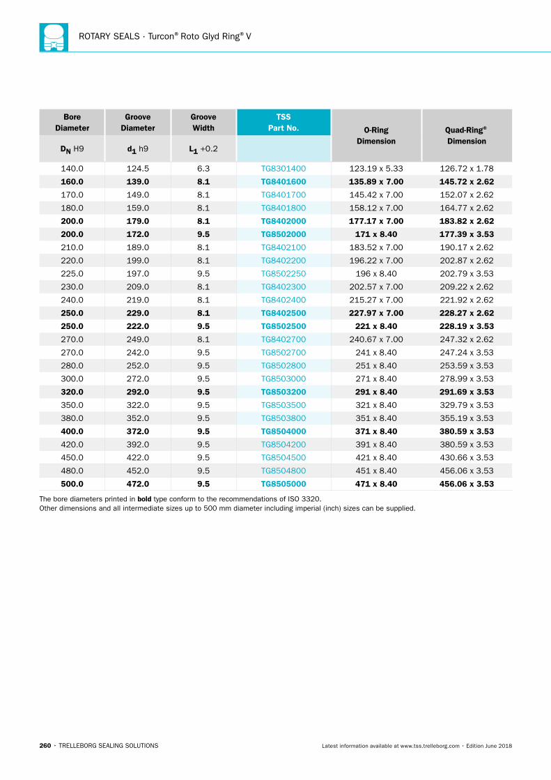
ROTARY SEALS · Turcon®Roto Glyd Ring®V
260 • TRELLEBORG SEALING SOLUTIONS Latest information available at www.tss.trelleborg.com • Edition June 2018
BoreDiameter
Groove Diameter
Groove Width
TSS Part No. O-Ring
DimensionQuad-Ring®
DimensionDN H9 d1 h9 L1 +0.2
140.0 124.5 6.3 TG8301400 123.19 x 5.33 126.72 x 1.78
160.0 139.0 8.1 TG8401600 135.89 x 7.00 145.72 x 2.62
170.0 149.0 8.1 TG8401700 145.42 x 7.00 152.07 x 2.62
180.0 159.0 8.1 TG8401800 158.12 x 7.00 164.77 x 2.62
200.0 179.0 8.1 TG8402000 177.17 x 7.00 183.82 x 2.62
200.0 172.0 9.5 TG8502000 171 x 8.40 177.39 x 3.53
210.0 189.0 8.1 TG8402100 183.52 x 7.00 190.17 x 2.62
220.0 199.0 8.1 TG8402200 196.22 x 7.00 202.87 x 2.62
225.0 197.0 9.5 TG8502250 196 x 8.40 202.79 x 3.53
230.0 209.0 8.1 TG8402300 202.57 x 7.00 209.22 x 2.62
240.0 219.0 8.1 TG8402400 215.27 x 7.00 221.92 x 2.62
250.0 229.0 8.1 TG8402500 227.97 x 7.00 228.27 x 2.62
250.0 222.0 9.5 TG8502500 221 x 8.40 228.19 x 3.53
270.0 249.0 8.1 TG8402700 240.67 x 7.00 247.32 x 2.62
270.0 242.0 9.5 TG8502700 241 x 8.40 247.24 x 3.53
280.0 252.0 9.5 TG8502800 251 x 8.40 253.59 x 3.53
300.0 272.0 9.5 TG8503000 271 x 8.40 278.99 x 3.53
320.0 292.0 9.5 TG8503200 291 x 8.40 291.69 x 3.53
350.0 322.0 9.5 TG8503500 321 x 8.40 329.79 x 3.53
380.0 352.0 9.5 TG8503800 351 x 8.40 355.19 x 3.53
400.0 372.0 9.5 TG8504000 371 x 8.40 380.59 x 3.53
420.0 392.0 9.5 TG8504200 391 x 8.40 380.59 x 3.53
450.0 422.0 9.5 TG8504500 421 x 8.40 430.66 x 3.53
480.0 452.0 9.5 TG8504800 451 x 8.40 456.06 x 3.53
500.0 472.0 9.5 TG8505000 471 x 8.40 456.06 x 3.53
The bore diameters printed in bold type conform to the recommendations of ISO 3320. Other dimensions and all intermediate sizes up to 500 mm diameter including imperial (inch) sizes can be supplied.
TRELLEBORG SEALING SOLUTIONS • 261Latest information available at www.tss.trelleborg.com • Edition June 2018
Zurcon®Roto Glyd Ring®S

ROTARY SEALS · Zurcon®Roto Glyd Ring®S
262 • TRELLEBORG SEALING SOLUTIONS Latest information available at www.tss.trelleborg.com • Edition June 2018
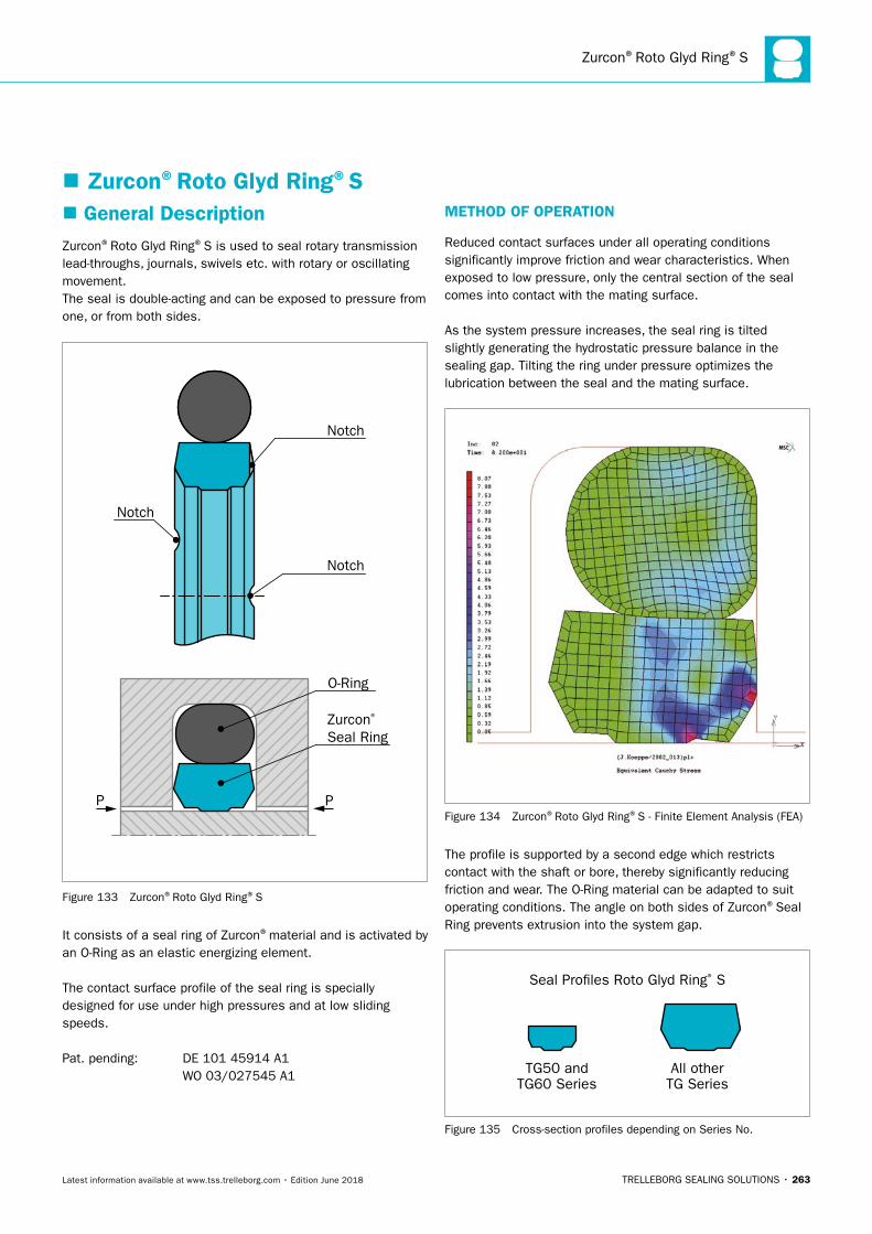
Zurcon®Roto Glyd Ring®S
TRELLEBORG SEALING SOLUTIONS • 263Latest information available at www.tss.trelleborg.com • Edition June 2018
� Zurcon®Roto Glyd Ring®S � General Description
Zurcon®Roto Glyd Ring®S is used to seal rotary transmission lead-throughs, journals, swivels etc. with rotary or oscillating movement.The seal is double-acting and can be exposed to pressure from one, or from both sides.
Notch
Notch
Notch
Zurcon® Seal Ring
O-Ring
PP
Figure 133 Zurcon®Roto Glyd Ring®S
It consists of a seal ring of Zurcon®material and is activated by an O-Ring as an elastic energizing element.
The contact surface profile of the seal ring is specially designed for use under high pressures and at low sliding speeds.
Pat. pending: DE 101 45914 A1 WO 03/027545 A1
METHOD OF OPERATION
Reduced contact surfaces under all operating conditions significantly improve friction and wear characteristics. When exposed to low pressure, only the central section of the seal comes into contact with the mating surface.
As the system pressure increases, the seal ring is tilted slightly generating the hydrostatic pressure balance in the sealing gap. Tilting the ring under pressure optimizes the lubrication between the seal and the mating surface.
Figure 134 Zurcon®Roto Glyd Ring®S - Finite Element Analysis (FEA)
The profile is supported by a second edge which restricts contact with the shaft or bore, thereby significantly reducing friction and wear. The O-Ring material can be adapted to suit operating conditions. The angle on both sides of Zurcon®Seal Ring prevents extrusion into the system gap.
Seal Pro�les Roto Glyd Ring® S
TG50 andTG60 Series
All otherTG Series
Figure 135 Cross-section profiles depending on Series No.
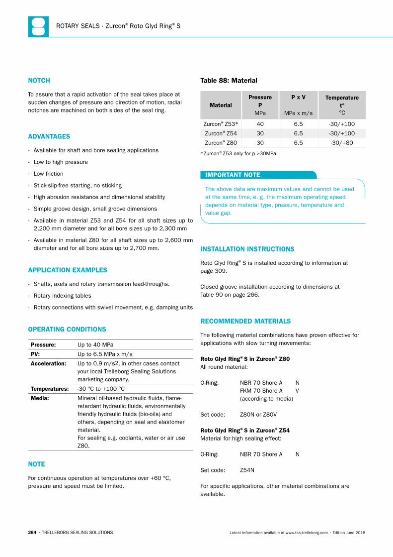
ROTARY SEALS · Zurcon®Roto Glyd Ring®S
264 • TRELLEBORG SEALING SOLUTIONS Latest information available at www.tss.trelleborg.com • Edition June 2018
NOTCH
To assure that a rapid activation of the seal takes place at sudden changes of pressure and direction of motion, radial notches are machined on both sides of the seal ring.
ADVANTAGES
- Available for shaft and bore sealing applications
- Low to high pressure
- Low friction
- Stick-slip-free starting, no sticking
- High abrasion resistance and dimensional stability
- Simple groove design, small groove dimensions
- Available in material Z53 and Z54 for all shaft sizes up to 2,200 mm diameter and for all bore sizes up to 2,300 mm
- Available in material Z80 for all shaft sizes up to 2,600 mm diameter and for all bore sizes up to 2,700 mm.
APPLICATION EXAMPLES
- Shafts, axels and rotary transmission lead-throughs.
- Rotary indexing tables
- Rotary connections with swivel movement, e.g. damping units
OPERATING CONDITIONS
Pressure: Up to 40 MPa
PV: Up to 6.5 MPa x m/s
Acceleration: Up to 0.9 m/s2, in other cases contact your local Trelleborg Sealing Solutions marketing company.
Temperatures: -30 °C to +100 °C
Media: Mineral oil-based hydraulic fluids, flame-retardant hydraulic fluids, environmentally friendly hydraulic fluids (bio-oils) and others, depending on seal and elastomer material. For sealing e.g. coolants, water or air use Z80.
NOTE
For continuous operation at temperatures over +60 °C, pressure and speed must be limited.
Table 88: Material
MaterialPressure
P MPa
P x V
MPa x m/s
Temperature t° °C
Zurcon®Z53* 40 6.5 -30/+100
Zurcon®Z54 30 6.5 -30/+100
Zurcon®Z80 30 6.5 -30/+80
*Zurcon®Z53 only for p >30MPa
IMPORTANT NOTE
The above data are maximum values and cannot be used at the same time, e. g. the maximum operating speed depends on material type, pressure, temperature and value gap.
INSTALLATION INSTRUCTIONS
Roto Glyd Ring®S is installed according to information at page 309.
Closed groove installation according to dimensions at Table 90 on page 266.
RECOMMENDED MATERIALS
The following material combinations have proven effective for applications with slow turning movements:
Roto Glyd Ring®S in Zurcon®Z80All round material:
O-Ring: NBR 70 Shore A N FKM 70 Shore A V (according to media)
Set code: Z80N or Z80V
Roto Glyd Ring®S in Zurcon®Z54Material for high sealing effect:
O-Ring: NBR 70 Shore A N
Set code: Z54N
For specific applications, other material combinations are available.
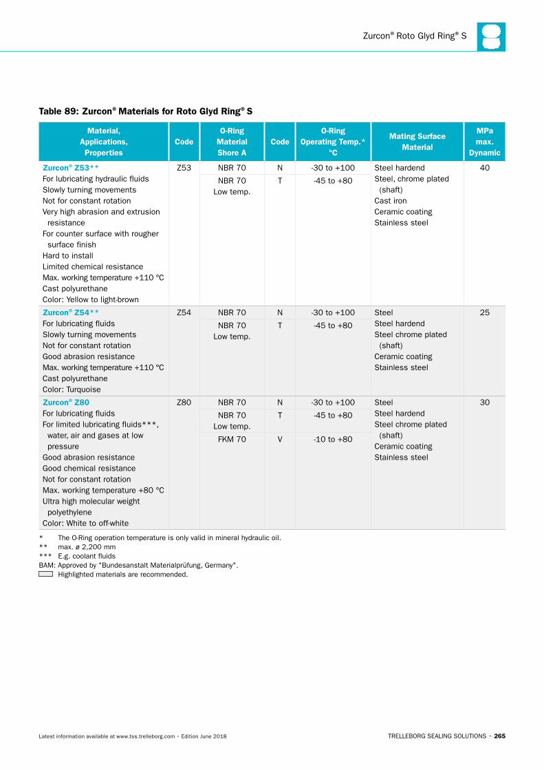
Zurcon®Roto Glyd Ring®S
TRELLEBORG SEALING SOLUTIONS • 265Latest information available at www.tss.trelleborg.com • Edition June 2018
Table 89: Zurcon®Materials for Roto Glyd Ring®S
Material, Applications, Properties
CodeO-Ring
Material Shore A
CodeO-Ring
Operating Temp.* °C
Mating Surface Material
MPa max.
Dynamic
Zurcon®Z53**For lubricating hydraulic fluidsSlowly turning movementsNot for constant rotationVery high abrasion and extrusion resistanceFor counter surface with rougher surface finishHard to installLimited chemical resistanceMax. working temperature +110 °CCast polyurethaneColor: Yellow to light-brown
Z53 NBR 70 N -30 to +100 Steel hardendSteel, chrome plated (shaft)Cast ironCeramic coatingStainless steel
40
NBR 70 Low temp.
T -45 to +80
Zurcon®Z54**For lubricating fluidsSlowly turning movementsNot for constant rotationGood abrasion resistanceMax. working temperature +110 °CCast polyurethaneColor: Turquoise
Z54 NBR 70 N -30 to +100 SteelSteel hardendSteel chrome plated (shaft)Ceramic coatingStainless steel
25
NBR 70 Low temp.
T -45 to +80
Zurcon®Z80For lubricating fluidsFor limited lubricating fluids***, water, air and gases at low pressureGood abrasion resistanceGood chemical resistance Not for constant rotationMax. working temperature +80 °CUltra high molecular weight polyethyleneColor: White to off-white
Z80 NBR 70 N -30 to +100 SteelSteel hardendSteel chrome plated (shaft)Ceramic coatingStainless steel
30
NBR 70 Low temp.
T -45 to +80
FKM 70 V -10 to +80
* The O-Ring operation temperature is only valid in mineral hydraulic oil. ** max. ø 2,200 mm *** E.g. coolant fluids BAM: Approved by "Bundesanstalt Materialprüfung, Germany".
Highlighted materials are recommended.
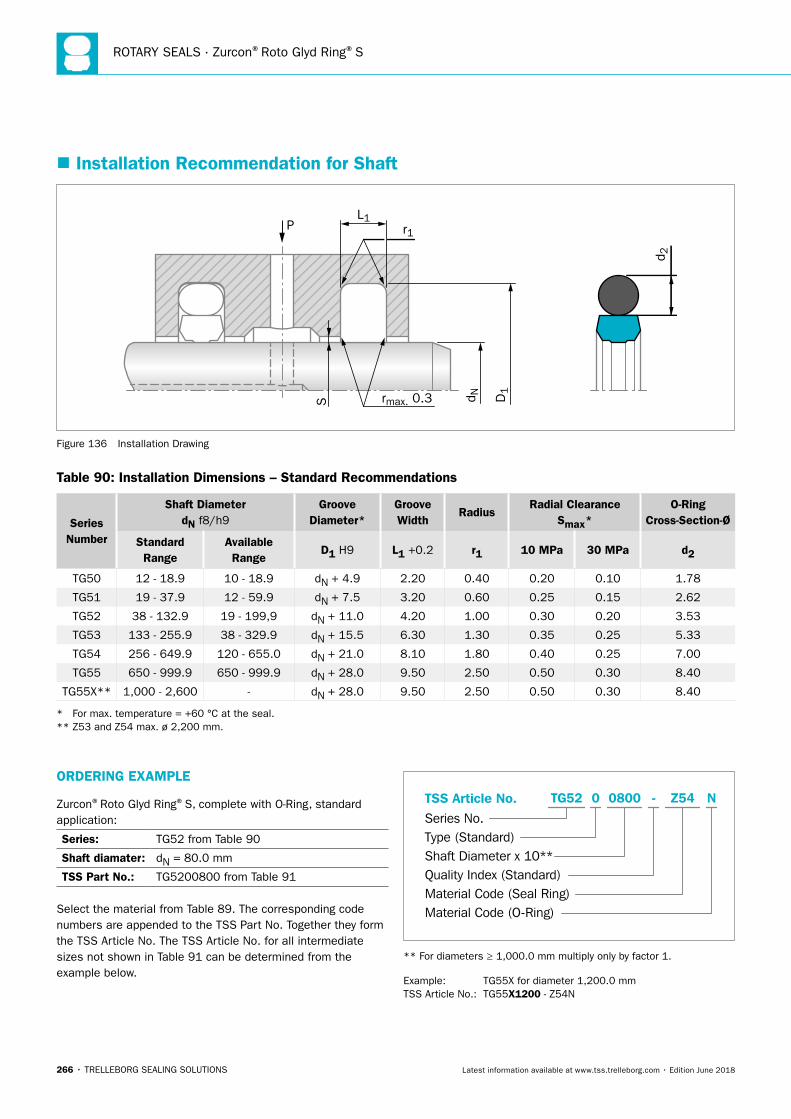
ROTARY SEALS · Zurcon®Roto Glyd Ring®S
266 • TRELLEBORG SEALING SOLUTIONS Latest information available at www.tss.trelleborg.com • Edition June 2018
ORDERING EXAMPLE
Zurcon®Roto Glyd Ring®S, complete with O-Ring, standard application:
Series: TG52 from Table 90
Shaft diamater: dN = 80.0 mm
TSS Part No.: TG5200800 from Table 91
Select the material from Table 89. The corresponding code numbers are appended to the TSS Part No. Together they form the TSS Article No. The TSS Article No. for all intermediate sizes not shown in Table 91 can be determined from the example below.
TSS Article No.Series No.Type (Standard)Shaft Diameter x 10**Quality Index (Standard)Material Code (Seal Ring)Material Code (O-Ring)
-TG52 0 0800 Z54 N
** For diameters ≥ 1,000.0 mm multiply only by factor 1.
Example: TG55X for diameter 1,200.0 mm TSS Article No.: TG55X1200 - Z54N
� Installation Recommendation for Shaft
PL1
S rmax. 0.3
r1
D1
d N
d 2
Figure 136 Installation Drawing
Table 90: Installation Dimensions – Standard Recommendations
Series Number
Shaft DiameterdN f8/h9
Groove Diameter*
Groove Width
RadiusRadial Clearance
Smax*O-Ring
Cross-Section-Ø
StandardRange
AvailableRange
D1 H9 L1 +0.2 r1 10 MPa 30 MPa d2
TG50 12 - 18.9 10 - 18.9 dN + 4.9 2.20 0.40 0.20 0.10 1.78
TG51 19 - 37.9 12 - 59.9 dN + 7.5 3.20 0.60 0.25 0.15 2.62
TG52 38 - 132.9 19 - 199,9 dN + 11.0 4.20 1.00 0.30 0.20 3.53
TG53 133 - 255.9 38 - 329.9 dN + 15.5 6.30 1.30 0.35 0.25 5.33
TG54 256 - 649.9 120 - 655.0 dN + 21.0 8.10 1.80 0.40 0.25 7.00
TG55 650 - 999.9 650 - 999.9 dN + 28.0 9.50 2.50 0.50 0.30 8.40
TG55X** 1,000 - 2,600 - dN + 28.0 9.50 2.50 0.50 0.30 8.40
* For max. temperature = +60 °C at the seal. ** Z53 and Z54 max. ø 2,200 mm.
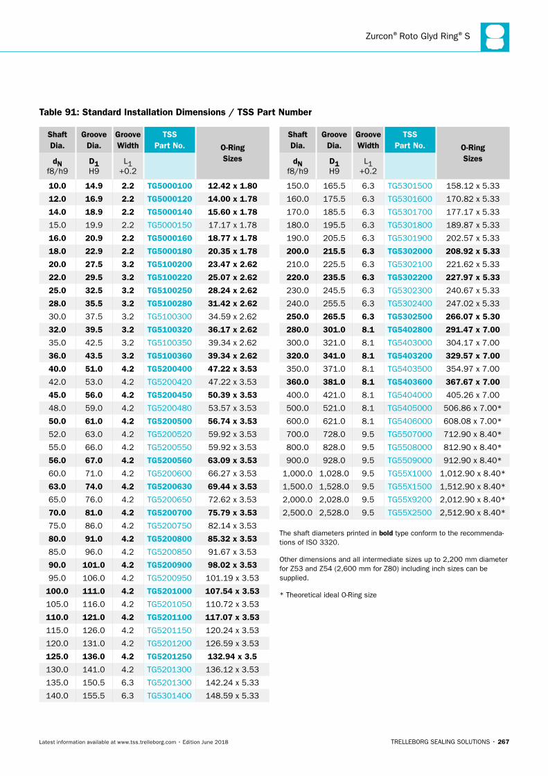
Zurcon®Roto Glyd Ring®S
TRELLEBORG SEALING SOLUTIONS • 267Latest information available at www.tss.trelleborg.com • Edition June 2018
Shaft Dia.
Groove Dia.
Groove Width
TSS Part No. O-Ring
SizesdN f8/h9
D1 H9
L1 +0.2
10.0 14.9 2.2 TG5000100 12.42 x 1.80
12.0 16.9 2.2 TG5000120 14.00 x 1.78
14.0 18.9 2.2 TG5000140 15.60 x 1.78
15.0 19.9 2.2 TG5000150 17.17 x 1.78
16.0 20.9 2.2 TG5000160 18.77 x 1.78
18.0 22.9 2.2 TG5000180 20.35 x 1.78
20.0 27.5 3.2 TG5100200 23.47 x 2.62
22.0 29.5 3.2 TG5100220 25.07 x 2.62
25.0 32.5 3.2 TG5100250 28.24 x 2.62
28.0 35.5 3.2 TG5100280 31.42 x 2.62
30.0 37.5 3.2 TG5100300 34.59 x 2.62
32.0 39.5 3.2 TG5100320 36.17 x 2.62
35.0 42.5 3.2 TG5100350 39.34 x 2.62
36.0 43.5 3.2 TG5100360 39.34 x 2.62
40.0 51.0 4.2 TG5200400 47.22 x 3.53
42.0 53.0 4.2 TG5200420 47.22 x 3.53
45.0 56.0 4.2 TG5200450 50.39 x 3.53
48.0 59.0 4.2 TG5200480 53.57 x 3.53
50.0 61.0 4.2 TG5200500 56.74 x 3.53
52.0 63.0 4.2 TG5200520 59.92 x 3.53
55.0 66.0 4.2 TG5200550 59.92 x 3.53
56.0 67.0 4.2 TG5200560 63.09 x 3.53
60.0 71.0 4.2 TG5200600 66.27 x 3.53
63.0 74.0 4.2 TG5200630 69.44 x 3.53
65.0 76.0 4.2 TG5200650 72.62 x 3.53
70.0 81.0 4.2 TG5200700 75.79 x 3.53
75.0 86.0 4.2 TG5200750 82.14 x 3.53
80.0 91.0 4.2 TG5200800 85.32 x 3.53
85.0 96.0 4.2 TG5200850 91.67 x 3.53
90.0 101.0 4.2 TG5200900 98.02 x 3.53
95.0 106.0 4.2 TG5200950 101.19 x 3.53
100.0 111.0 4.2 TG5201000 107.54 x 3.53
105.0 116.0 4.2 TG5201050 110.72 x 3.53
110.0 121.0 4.2 TG5201100 117.07 x 3.53
115.0 126.0 4.2 TG5201150 120.24 x 3.53
120.0 131.0 4.2 TG5201200 126.59 x 3.53
125.0 136.0 4.2 TG5201250 132.94 x 3.5
130.0 141.0 4.2 TG5201300 136.12 x 3.53
135.0 150.5 6.3 TG5201300 142.24 x 5.33
140.0 155.5 6.3 TG5301400 148.59 x 5.33
Shaft Dia.
Groove Dia.
Groove Width
TSS Part No. O-Ring
SizesdN f8/h9
D1 H9
L1 +0.2
150.0 165.5 6.3 TG5301500 158.12 x 5.33
160.0 175.5 6.3 TG5301600 170.82 x 5.33
170.0 185.5 6.3 TG5301700 177.17 x 5.33
180.0 195.5 6.3 TG5301800 189.87 x 5.33
190.0 205.5 6.3 TG5301900 202.57 x 5.33
200.0 215.5 6.3 TG5302000 208.92 x 5.33
210.0 225.5 6.3 TG5302100 221.62 x 5.33
220.0 235.5 6.3 TG5302200 227.97 x 5.33
230.0 245.5 6.3 TG5302300 240.67 x 5.33
240.0 255.5 6.3 TG5302400 247.02 x 5.33
250.0 265.5 6.3 TG5302500 266.07 x 5.30
280.0 301.0 8.1 TG5402800 291.47 x 7.00
300.0 321.0 8.1 TG5403000 304.17 x 7.00
320.0 341.0 8.1 TG5403200 329.57 x 7.00
350.0 371.0 8.1 TG5403500 354.97 x 7.00
360.0 381.0 8.1 TG5403600 367.67 x 7.00
400.0 421.0 8.1 TG5404000 405.26 x 7.00
500.0 521.0 8.1 TG5405000 506.86 x 7.00*
600.0 621.0 8.1 TG5406000 608.08 x 7.00*
700.0 728.0 9.5 TG5507000 712.90 x 8.40*
800.0 828.0 9.5 TG5508000 812.90 x 8.40*
900.0 928.0 9.5 TG5509000 912.90 x 8.40*
1,000.0 1,028.0 9.5 TG55X1000 1,012.90 x 8.40*
1,500.0 1,528.0 9.5 TG55X1500 1,512.90 x 8.40*
2,000.0 2,028.0 9.5 TG55X9200 2,012.90 x 8.40*
2,500.0 2,528.0 9.5 TG55X2500 2,512.90 x 8.40*
The shaft diameters printed in bold type conform to the recommenda-tions of ISO 3320.
Other dimensions and all intermediate sizes up to 2,200 mm diameter for Z53 and Z54 (2,600 mm for Z80) including inch sizes can be supplied.
* Theoretical ideal O-Ring size
Table 91: Standard Installation Dimensions / TSS Part Number
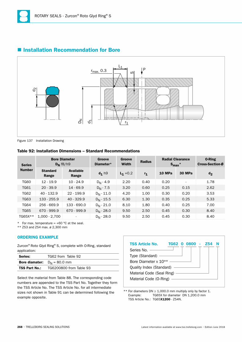
ROTARY SEALS · Zurcon®Roto Glyd Ring®S
268 • TRELLEBORG SEALING SOLUTIONS Latest information available at www.tss.trelleborg.com • Edition June 2018
ORDERING EXAMPLE
Zurcon®Roto Glyd Ring®S, complete with O-Ring, standard application:
Series: TG62 from Table 92
Bore diamater: DN = 80.0 mm
TSS Part No.: TG6200800 from Table 93
Select the material from Table 88. The corresponding code numbers are appended to the TSS Part No. Together they form the TSS Article No. The TSS Article No. for all intermediate sizes not shown in Table 91 can be determined following the example opposite.
TSS Article No.Series No.Type (Standard)Bore Diameter x 10**Quality Index (Standard)Material Code (Seal Ring)Material Code (O-Ring)
-TG62 0 0800 Z54 N
** For diameters DN ≥ 1,000.0 mm multiply only by factor 1. Example: TG65X for diameter DN 1,200.0 mm TSS Article No.: TG65X1200 - Z54N.
� Installation Recommendation for Bore
P
S
L1rmax. 0.3
r1
d 2
DN
d 1
Figure 137 Installation Drawing
Table 92: Installation Dimensions – Standard Recommendations
Series Number
Bore DiameterDN f8/h9
Groove Diameter*
Groove Width
RadiusRadial Clearance
Smax*O-Ring
Cross-Section-Ø
StandardRange
AvailableRange
d1 h9 L1 +0.2 r1 10 MPa 30 MPa d2
TG60 12 - 19.9 10 - 24.9 DN - 4.9 2.20 0.40 0.20 - 1.78
TG61 20 - 39.9 14 - 69.9 DN - 7.5 3.20 0.60 0.25 0.15 2.62
TG62 40 - 132.9 22 - 199.9 DN - 11.0 4.20 1.00 0.30 0.20 3.53
TG63 133 - 255.9 40 - 329.9 DN - 15.5 6.30 1.30 0.35 0.25 5.33
TG64 256 - 669.9 133 - 690.0 DN - 21.0 8.10 1.80 0.40 0.25 7.00
TG65 670 - 999.9 670 - 999.9 DN - 28.0 9.50 2.50 0.45 0.30 8.40
TG65X** 1,000 - 2,700 - DN - 28.0 9.50 2.50 0.45 0.30 8.40
* For max. temperature = +60 °C at the seal. ** Z53 and Z54 max. ø 2,300 mm
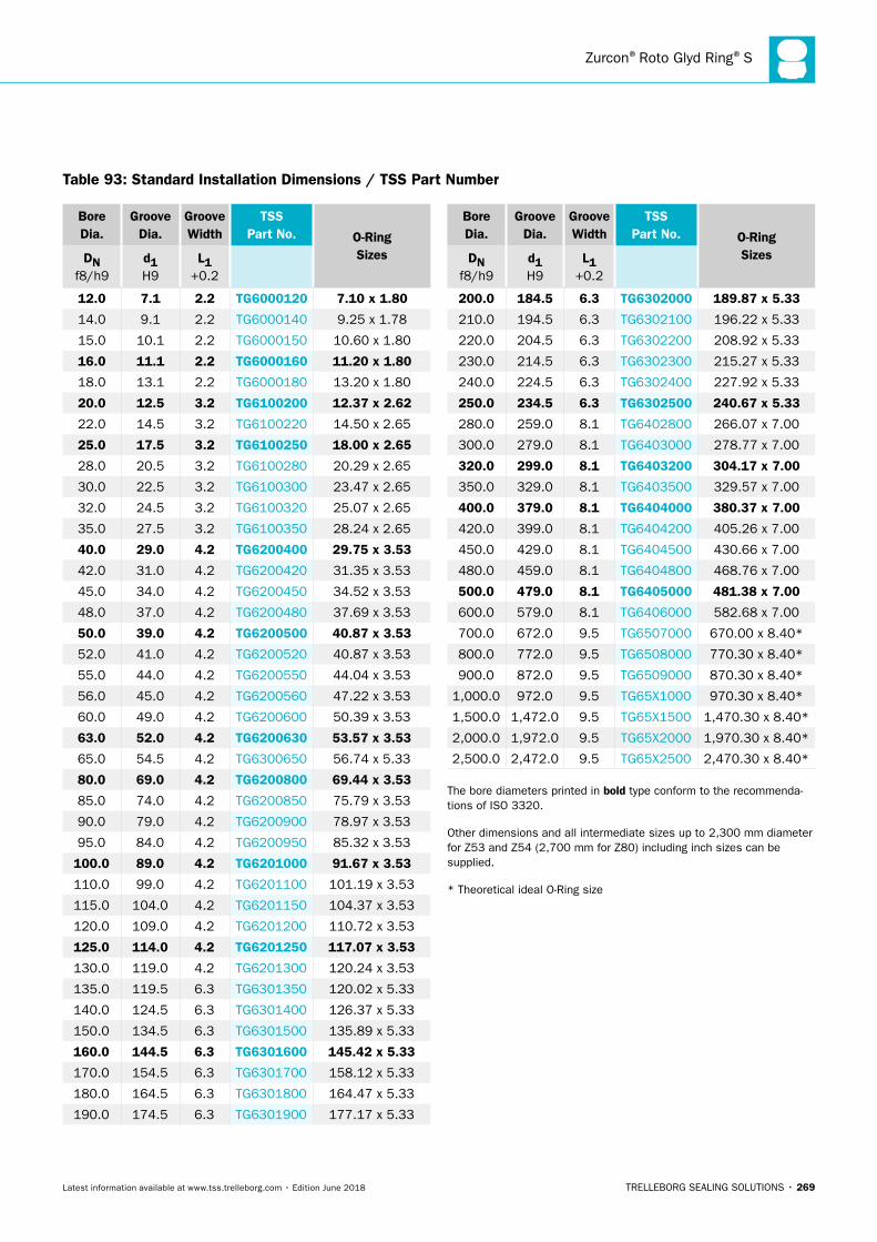
Zurcon®Roto Glyd Ring®S
TRELLEBORG SEALING SOLUTIONS • 269Latest information available at www.tss.trelleborg.com • Edition June 2018
Bore Dia.
Groove Dia.
Groove Width
TSS Part No. O-Ring
SizesDN f8/h9
d1 H9
L1 +0.2
12.0 7.1 2.2 TG6000120 7.10 x 1.80
14.0 9.1 2.2 TG6000140 9.25 x 1.78
15.0 10.1 2.2 TG6000150 10.60 x 1.80
16.0 11.1 2.2 TG6000160 11.20 x 1.80
18.0 13.1 2.2 TG6000180 13.20 x 1.80
20.0 12.5 3.2 TG6100200 12.37 x 2.62
22.0 14.5 3.2 TG6100220 14.50 x 2.65
25.0 17.5 3.2 TG6100250 18.00 x 2.65
28.0 20.5 3.2 TG6100280 20.29 x 2.65
30.0 22.5 3.2 TG6100300 23.47 x 2.65
32.0 24.5 3.2 TG6100320 25.07 x 2.65
35.0 27.5 3.2 TG6100350 28.24 x 2.65
40.0 29.0 4.2 TG6200400 29.75 x 3.53
42.0 31.0 4.2 TG6200420 31.35 x 3.53
45.0 34.0 4.2 TG6200450 34.52 x 3.53
48.0 37.0 4.2 TG6200480 37.69 x 3.53
50.0 39.0 4.2 TG6200500 40.87 x 3.53
52.0 41.0 4.2 TG6200520 40.87 x 3.53
55.0 44.0 4.2 TG6200550 44.04 x 3.53
56.0 45.0 4.2 TG6200560 47.22 x 3.53
60.0 49.0 4.2 TG6200600 50.39 x 3.53
63.0 52.0 4.2 TG6200630 53.57 x 3.53
65.0 54.5 4.2 TG6300650 56.74 x 5.33
80.0 69.0 4.2 TG6200800 69.44 x 3.53
85.0 74.0 4.2 TG6200850 75.79 x 3.53
90.0 79.0 4.2 TG6200900 78.97 x 3.53
95.0 84.0 4.2 TG6200950 85.32 x 3.53
100.0 89.0 4.2 TG6201000 91.67 x 3.53
110.0 99.0 4.2 TG6201100 101.19 x 3.53
115.0 104.0 4.2 TG6201150 104.37 x 3.53
120.0 109.0 4.2 TG6201200 110.72 x 3.53
125.0 114.0 4.2 TG6201250 117.07 x 3.53
130.0 119.0 4.2 TG6201300 120.24 x 3.53
135.0 119.5 6.3 TG6301350 120.02 x 5.33
140.0 124.5 6.3 TG6301400 126.37 x 5.33
150.0 134.5 6.3 TG6301500 135.89 x 5.33
160.0 144.5 6.3 TG6301600 145.42 x 5.33
170.0 154.5 6.3 TG6301700 158.12 x 5.33
180.0 164.5 6.3 TG6301800 164.47 x 5.33
190.0 174.5 6.3 TG6301900 177.17 x 5.33
Bore Dia.
Groove Dia.
Groove Width
TSS Part No. O-Ring
SizesDN f8/h9
d1 H9
L1 +0.2
200.0 184.5 6.3 TG6302000 189.87 x 5.33
210.0 194.5 6.3 TG6302100 196.22 x 5.33
220.0 204.5 6.3 TG6302200 208.92 x 5.33
230.0 214.5 6.3 TG6302300 215.27 x 5.33
240.0 224.5 6.3 TG6302400 227.92 x 5.33
250.0 234.5 6.3 TG6302500 240.67 x 5.33
280.0 259.0 8.1 TG6402800 266.07 x 7.00
300.0 279.0 8.1 TG6403000 278.77 x 7.00
320.0 299.0 8.1 TG6403200 304.17 x 7.00
350.0 329.0 8.1 TG6403500 329.57 x 7.00
400.0 379.0 8.1 TG6404000 380.37 x 7.00
420.0 399.0 8.1 TG6404200 405.26 x 7.00
450.0 429.0 8.1 TG6404500 430.66 x 7.00
480.0 459.0 8.1 TG6404800 468.76 x 7.00
500.0 479.0 8.1 TG6405000 481.38 x 7.00
600.0 579.0 8.1 TG6406000 582.68 x 7.00
700.0 672.0 9.5 TG6507000 670.00 x 8.40*
800.0 772.0 9.5 TG6508000 770.30 x 8.40*
900.0 872.0 9.5 TG6509000 870.30 x 8.40*
1,000.0 972.0 9.5 TG65X1000 970.30 x 8.40*
1,500.0 1,472.0 9.5 TG65X1500 1,470.30 x 8.40*
2,000.0 1,972.0 9.5 TG65X2000 1,970.30 x 8.40*
2,500.0 2,472.0 9.5 TG65X2500 2,470.30 x 8.40*
The bore diameters printed in bold type conform to the recommenda-tions of ISO 3320.
Other dimensions and all intermediate sizes up to 2,300 mm diameter for Z53 and Z54 (2,700 mm for Z80) including inch sizes can be supplied.
* Theoretical ideal O-Ring size
Table 93: Standard Installation Dimensions / TSS Part Number

ROTARY SEALS · Zurcon®Roto Glyd Ring®S
270 • TRELLEBORG SEALING SOLUTIONS Latest information available at www.tss.trelleborg.com • Edition June 2018
TRELLEBORG SEALING SOLUTIONS • 271Latest information available at www.tss.trelleborg.com • Edition June 2018
Turcon®Roto Variseal

ROTARY SEALS · Turcon® Roto Variseal®
272 • TRELLEBORG SEALING SOLUTIONS Latest information available at www.tss.trelleborg.com • Edition June 2018
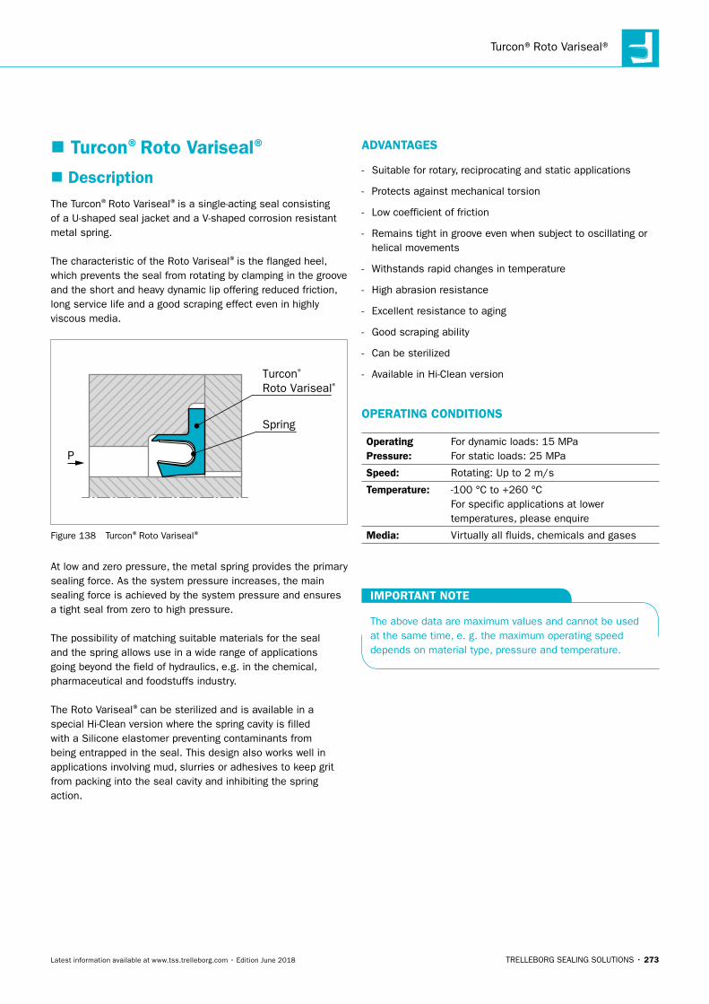
Turcon®Roto Variseal®
TRELLEBORG SEALING SOLUTIONS • 273Latest information available at www.tss.trelleborg.com • Edition June 2018
� Turcon®Roto Variseal®
� DescriptionThe Turcon®Roto Variseal®is a single-acting seal consisting of a U-shaped seal jacket and a V-shaped corrosion resistant metal spring.
The characteristic of the Roto Variseal®is the flanged heel, which prevents the seal from rotating by clamping in the groove and the short and heavy dynamic lip offering reduced friction, long service life and a good scraping effect even in highly viscous media.
P
Turcon® Roto Variseal®
Spring
Figure 138 Turcon®Roto Variseal®
At low and zero pressure, the metal spring provides the primary sealing force. As the system pressure increases, the main sealing force is achieved by the system pressure and ensures a tight seal from zero to high pressure.
The possibility of matching suitable materials for the seal and the spring allows use in a wide range of applications going beyond the field of hydraulics, e.g. in the chemical, pharmaceutical and foodstuffs industry.
The Roto Variseal®can be sterilized and is available in a special Hi-Clean version where the spring cavity is filled with a Silicone elastomer preventing contaminants from being entrapped in the seal. This design also works well in applications involving mud, slurries or adhesives to keep grit from packing into the seal cavity and inhibiting the spring action.
ADVANTAGES
- Suitable for rotary, reciprocating and static applications
- Protects against mechanical torsion
- Low coefficient of friction
- Remains tight in groove even when subject to oscillating or helical movements
- Withstands rapid changes in temperature
- High abrasion resistance
- Excellent resistance to aging
- Good scraping ability
- Can be sterilized
- Available in Hi-Clean version
OPERATING CONDITIONS
Operating Pressure:
For dynamic loads: 15 MPaFor static loads: 25 MPa
Speed: Rotating: Up to 2 m/s
Temperature: -100 °C to +260 °CFor specific applications at lower temperatures, please enquire
Media: Virtually all fluids, chemicals and gases
IMPORTANT NOTE
The above data are maximum values and cannot be used at the same time, e. g. the maximum operating speed depends on material type, pressure and temperature.
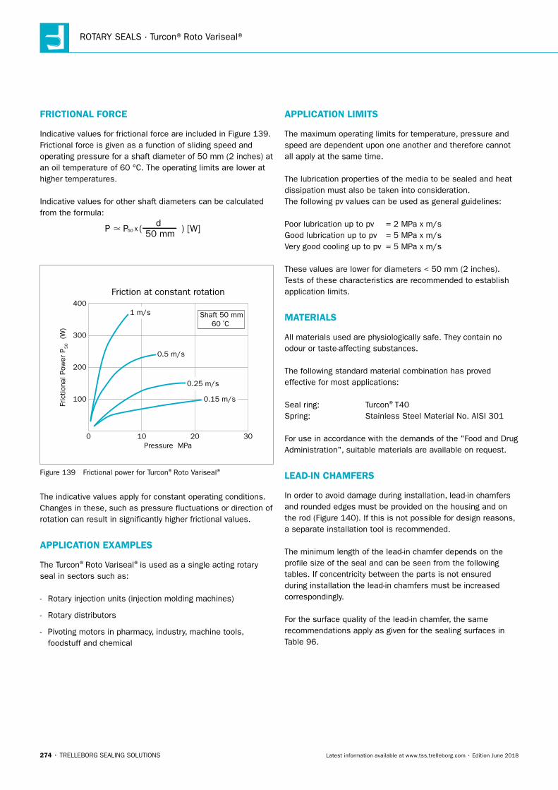
ROTARY SEALS · Turcon®Roto Variseal®
274 • TRELLEBORG SEALING SOLUTIONS Latest information available at www.tss.trelleborg.com • Edition June 2018
FRICTIONAL FORCE
Indicative values for frictional force are included in Figure 139. Frictional force is given as a function of sliding speed and operating pressure for a shaft diameter of 50 mm (2 inches) at an oil temperature of 60 °C. The operating limits are lower at higher temperatures.
Indicative values for other shaft diameters can be calculated from the formula:
P � P50 x ( ) [W]d50 mm
Fric
tiona
l Pow
er P
50 (W
)
Friction at constant rotation
0
100
200
300
400
10Pressure MPa
20 30
1 m/s
0.5 m/s
0.25 m/s
0.15 m/s
Shaft 50 mm60 ºC
Figure 139 Frictional power for Turcon®Roto Variseal®
The indicative values apply for constant operating conditions. Changes in these, such as pressure fluctuations or direction of rotation can result in significantly higher frictional values.
APPLICATION EXAMPLES
The Turcon®Roto Variseal®is used as a single acting rotary seal in sectors such as:
- Rotary injection units (injection molding machines)
- Rotary distributors
- Pivoting motors in pharmacy, industry, machine tools, foodstuff and chemical
APPLICATION LIMITS
The maximum operating limits for temperature, pressure and speed are dependent upon one another and therefore cannot all apply at the same time.
The lubrication properties of the media to be sealed and heat dissipation must also be taken into consideration.The following pv values can be used as general guidelines:
Poor lubrication up to pv = 2 MPa x m/s Good lubrication up to pv = 5 MPa x m/s Very good cooling up to pv = 5 MPa x m/s
These values are lower for diameters < 50 mm (2 inches). Tests of these characteristics are recommended to establish application limits.
MATERIALS
All materials used are physiologically safe. They contain no odour or taste-affecting substances.
The following standard material combination has proved effective for most applications:
Seal ring: Turcon®T40Spring: Stainless Steel Material No. AISI 301
For use in accordance with the demands of the "Food and Drug Administration", suitable materials are available on request.
LEAD-IN CHAMFERS
In order to avoid damage during installation, lead-in chamfers and rounded edges must be provided on the housing and on the rod (Figure 140). If this is not possible for design reasons, a separate installation tool is recommended.
The minimum length of the lead-in chamfer depends on the profile size of the seal and can be seen from the following tables. If concentricity between the parts is not ensured during installation the lead-in chamfers must be increased correspondingly.
For the surface quality of the lead-in chamfer, the same recommendations apply as given for the sealing surfaces in Table 96.
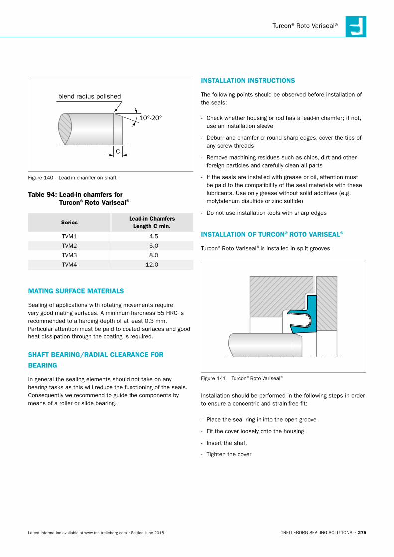
Turcon®Roto Variseal®
TRELLEBORG SEALING SOLUTIONS • 275Latest information available at www.tss.trelleborg.com • Edition June 2018
C
blend radius polished
10°-20°
Figure 140 Lead-in chamfer on shaft
Table 94: Lead-in chamfers for Turcon®Roto Variseal®
SeriesLead-in Chamfers
Length C min.
TVM1 4.5
TVM2 5.0
TVM3 8.0
TVM4 12.0
MATING SURFACE MATERIALS
Sealing of applications with rotating movements require very good mating surfaces. A minimum hardness 55 HRC is recommended to a harding depth of at least 0.3 mm.Particular attention must be paid to coated surfaces and good heat dissipation through the coating is required.
SHAFT BEARING/RADIAL CLEARANCE FOR
BEARING
In general the sealing elements should not take on any bearing tasks as this will reduce the functioning of the seals. Consequently we recommend to guide the components by means of a roller or slide bearing.
INSTALLATION INSTRUCTIONS
The following points should be observed before installation of the seals:
- Check whether housing or rod has a lead-in chamfer; if not, use an installation sleeve
- Deburr and chamfer or round sharp edges, cover the tips of any screw threads
- Remove machining residues such as chips, dirt and other foreign particles and carefully clean all parts
- If the seals are installed with grease or oil, attention must be paid to the compatibility of the seal materials with these lubricants. Use only grease without solid additives (e.g. molybdenum disulfide or zinc sulfide)
- Do not use installation tools with sharp edges
INSTALLATION OF TURCON®ROTO VARISEAL®
Turcon®Roto Variseal®is installed in split grooves.
Figure 141 Turcon®Roto Variseal®
Installation should be performed in the following steps in order to ensure a concentric and strain-free fit:
- Place the seal ring in into the open groove
- Fit the cover loosely onto the housing
- Insert the shaft
- Tighten the cover
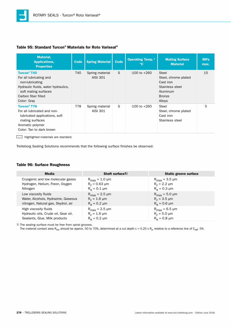
ROTARY SEALS · Turcon®Roto Variseal®
276 • TRELLEBORG SEALING SOLUTIONS Latest information available at www.tss.trelleborg.com • Edition June 2018
Table 95: Standard Turcon®Materials for Roto Variseal®
Material, Applications, Properties
Code Spring Material CodeOperating Temp.*
°CMating Surface
MaterialMPa max.
Turcon®T40For all lubricating and non-lubricatingHydraulic fluids, water hydraulics, soft mating surfacesCarbon fiber filledColor: Gray
T40 Spring material AISI 301
S -100 to +260 SteelSteel, chrome platedCast ironStainless steelAluminumBronzeAlloys
15
Turcon®T78For all lubricated and non- lubricated applications, soft mating surfacesAromatic polymerColor: Tan to dark brown
T78 Spring material AISI 301
S -100 to +260 SteelSteel, chrome platedCast ironStainless steel
5
Highlighted materials are standard.
Trelleborg Sealing Solutions recommends that the following surface finishes be observed:
Table 96: Surface Roughness
Media Shaft surface1) Static groove surface
Cryogenic and low molecular gases Hydrogen, Helium, Freon, Oxygen Nitrogen
Rmax = 1.0 μm Rz = 0.63 μm Ra = 0.1 μm
Rmax = 3.5 μm Rz = 2.2 μm Ra = 0.3 μm
Low viscosity fluids Water, Alcohols, Hydrazine, Gaseous nitrogen, Natural gas, Skydrol, air
Rmax = 2.5 μm Rz = 1.6 μm Ra = 0.2 μm
Rmax = 5.0 μm Rz = 3.5 μm Ra = 0.6 μm
High viscosity fluids Hydraulic oils, Crude oil, Gear oil, Sealants, Glue, Milk products
Rmax = 2.5 μm Rz = 1.6 μm Ra = 0.2 μm
Rmax = 6.5 μm Rz = 5.0 μm Ra = 0.8 μm
1) The sealing surface must be free from spiral grooves. The material contact area Rmr should be approx. 50 to 70%, determined at a cut depth c = 0.25 x Rz, relative to a reference line of Cref. 5%.
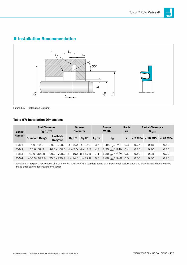
Turcon®Roto Variseal®
TRELLEBORG SEALING SOLUTIONS • 277Latest information available at www.tss.trelleborg.com • Edition June 2018
� Installation Recommendation
r
kD2
d N
S
D1
30°
L1L2
Figure 142 Installation Drawing
Table 97: Installation Dimensions
Series Number
Rod DiameterdN f8/h9
Groove Diameter
Groove Width
Radi-us
Radial ClearanceSmax
Standard RangeAvailable Range1) D1 H9 D2 H10 L1 min L2 r < 2 MPa < 10 MPa < 20 MPa
TVM1 5.0 - 19.9 20.0 - 200.0 d + 5.0 d + 9.0 3.6 0.85 +0 / -0.1 0.3 0.25 0.15 0.10
TVM2 20.0 - 39.9 10.0 - 400.0 d + 7.0 d + 12.5 4.8 1.35 +0 / -0.15 0.4 0.35 0.20 0.15
TVM3 40.0 - 399.9 20.0 - 700.0 d + 10.5 d + 17.5 7.1 1.80 +0 / -0.20 0.5 0.50 0.25 0.20
TVM4 400.0 - 999.9 35.0 - 999.9 d + 14.0 d + 22.0 9.5 2.80 +0 / -0.20 0.5 0.60 0.30 0.25
1) Available on request. Application of a seal series outside of the standard range can impair seal performance and stability and should only be made after careful testing and evaluation.
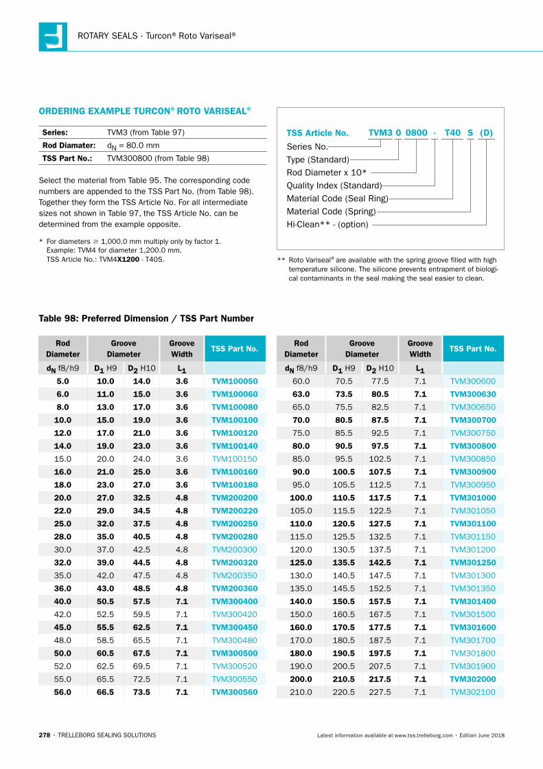
ROTARY SEALS · Turcon®Roto Variseal®
278 • TRELLEBORG SEALING SOLUTIONS Latest information available at www.tss.trelleborg.com • Edition June 2018
Rod Diameter
Groove Diameter
Groove Width
TSS Part No.
dN f8/h9 D1 H9 D2 H10 L15.0 10.0 14.0 3.6 TVM100050
6.0 11.0 15.0 3.6 TVM100060
8.0 13.0 17.0 3.6 TVM100080
10.0 15.0 19.0 3.6 TVM100100
12.0 17.0 21.0 3.6 TVM100120
14.0 19.0 23.0 3.6 TVM100140
15.0 20.0 24.0 3.6 TVM100150
16.0 21.0 25.0 3.6 TVM100160
18.0 23.0 27.0 3.6 TVM100180
20.0 27.0 32.5 4.8 TVM200200
22.0 29.0 34.5 4.8 TVM200220
25.0 32.0 37.5 4.8 TVM200250
28.0 35.0 40.5 4.8 TVM200280
30.0 37.0 42.5 4.8 TVM200300
32.0 39.0 44.5 4.8 TVM200320
35.0 42.0 47.5 4.8 TVM200350
36.0 43.0 48.5 4.8 TVM200360
40.0 50.5 57.5 7.1 TVM300400
42.0 52.5 59.5 7.1 TVM300420
45.0 55.5 62.5 7.1 TVM300450
48.0 58.5 65.5 7.1 TVM300480
50.0 60.5 67.5 7.1 TVM300500
52.0 62.5 69.5 7.1 TVM300520
55.0 65.5 72.5 7.1 TVM300550
56.0 66.5 73.5 7.1 TVM300560
Rod Diameter
Groove Diameter
Groove Width
TSS Part No.
dN f8/h9 D1 H9 D2 H10 L160.0 70.5 77.5 7.1 TVM300600
63.0 73.5 80.5 7.1 TVM300630
65.0 75.5 82.5 7.1 TVM300650
70.0 80.5 87.5 7.1 TVM300700
75.0 85.5 92.5 7.1 TVM300750
80.0 90.5 97.5 7.1 TVM300800
85.0 95.5 102.5 7.1 TVM300850
90.0 100.5 107.5 7.1 TVM300900
95.0 105.5 112.5 7.1 TVM300950
100.0 110.5 117.5 7.1 TVM301000
105.0 115.5 122.5 7.1 TVM301050
110.0 120.5 127.5 7.1 TVM301100
115.0 125.5 132.5 7.1 TVM301150
120.0 130.5 137.5 7.1 TVM301200
125.0 135.5 142.5 7.1 TVM301250
130.0 140.5 147.5 7.1 TVM301300
135.0 145.5 152.5 7.1 TVM301350
140.0 150.5 157.5 7.1 TVM301400
150.0 160.5 167.5 7.1 TVM301500
160.0 170.5 177.5 7.1 TVM301600
170.0 180.5 187.5 7.1 TVM301700
180.0 190.5 197.5 7.1 TVM301800
190.0 200.5 207.5 7.1 TVM301900
200.0 210.5 217.5 7.1 TVM302000
210.0 220.5 227.5 7.1 TVM302100
ORDERING EXAMPLE TURCON®ROTO VARISEAL®
Series: TVM3 (from Table 97)
Rod Diamater: dN = 80.0 mm
TSS Part No.: TVM300800 (from Table 98)
Select the material from Table 95. The corresponding code numbers are appended to the TSS Part No. (from Table 98). Together they form the TSS Article No. For all intermediate sizes not shown in Table 97, the TSS Article No. can be determined from the example opposite.
* For diameters 1,000.0 mm multiply only by factor 1. Example: TVM4 for diameter 1,200.0 mm. TSS Article No.: TVM4X1200 - T40S.
TSS Article No.
Series No.Type (Standard)Rod Diameter x 10*Quality Index (Standard)Material Code (Seal Ring)Material Code (Spring)Hi-Clean** - (option)
-TVM3 0 0800 T40 S (D)
** Roto Variseal®are available with the spring groove filled with high temperature silicone. The silicone prevents entrapment of biologi- cal contaminants in the seal making the seal easier to clean.
Table 98: Preferred Dimension / TSS Part Number
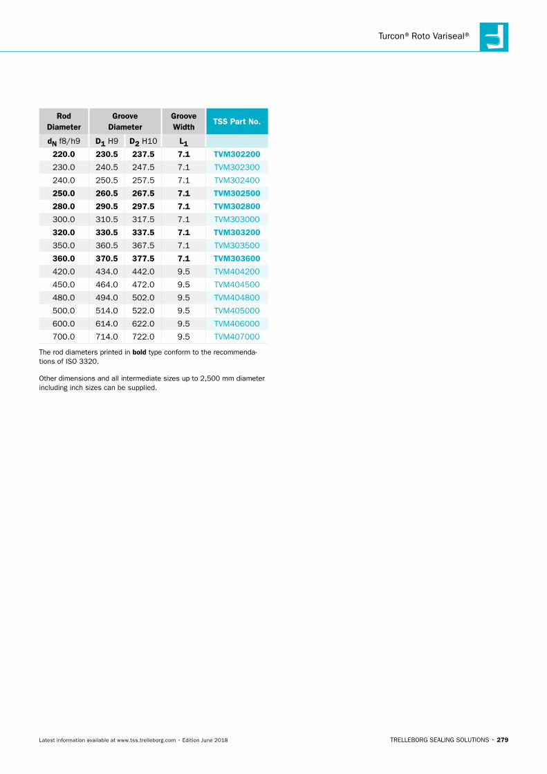
Turcon®Roto Variseal®
TRELLEBORG SEALING SOLUTIONS • 279Latest information available at www.tss.trelleborg.com • Edition June 2018
Rod Diameter
Groove Diameter
Groove Width
TSS Part No.
dN f8/h9 D1 H9 D2 H10 L1220.0 230.5 237.5 7.1 TVM302200
230.0 240.5 247.5 7.1 TVM302300
240.0 250.5 257.5 7.1 TVM302400
250.0 260.5 267.5 7.1 TVM302500
280.0 290.5 297.5 7.1 TVM302800
300.0 310.5 317.5 7.1 TVM303000
320.0 330.5 337.5 7.1 TVM303200
350.0 360.5 367.5 7.1 TVM303500
360.0 370.5 377.5 7.1 TVM303600
420.0 434.0 442.0 9.5 TVM404200
450.0 464.0 472.0 9.5 TVM404500
480.0 494.0 502.0 9.5 TVM404800
500.0 514.0 522.0 9.5 TVM405000
600.0 614.0 622.0 9.5 TVM406000
700.0 714.0 722.0 9.5 TVM407000
The rod diameters printed in bold type conform to the recommenda-tions of ISO 3320.
Other dimensions and all intermediate sizes up to 2,500 mm diameter including inch sizes can be supplied.

ROTARY SEALS · Turcon®Roto Variseal®
280 • TRELLEBORG SEALING SOLUTIONS Latest information available at www.tss.trelleborg.com • Edition June 2018
TRELLEBORG SEALING SOLUTIONS • 281Latest information available at www.tss.trelleborg.com • Edition June 2018
Turcon®Roto VL Seal®F

ROTARY SEALS · Turcon® Roto VL Seal® F
282 • TRELLEBORG SEALING SOLUTIONS Latest information available at www.tss.trelleborg.com • Edition June 2018
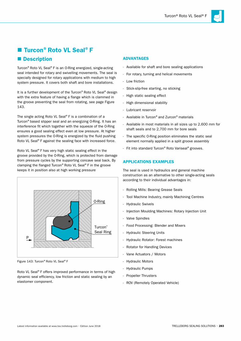
Turcon®Roto VL Seal®F
TRELLEBORG SEALING SOLUTIONS • 283Latest information available at www.tss.trelleborg.com • Edition June 2018
� DescriptionTurcon®Roto VL Seal®F is an O-Ring energized, single-acting seal intended for rotary and swivelling movements. The seal is specially designed for rotary applications with medium to high system pressure. It covers both shaft and bore installations.
It is a further development of the Turcon®Roto VL Seal®design with the extra feature of having a flange which is clammed in the groove preventing the seal from rotating, see page Figure 143.
The single acting Roto VL Seal®F is a combination of a Turcon®based slipper seal and an energizing O-Ring. It has an interference fit which together with the squeeze of the O-Ring ensures a good sealing effect even at low pressure. At higher system pressures the O-Ring is energized by the fluid pushing Roto VL Seal®F against the sealing face with increased force.
Roto VL Seal®F has very high static sealing effect in the groove provided by the O-Ring, which is protected from damage from pressure cycles by the supporting concave seal back. By clamping the flanged Turcon®Roto VL Seal®F in the groove keeps it in position also at high working pressure
P
Turcon® Seal Ring
O-Ring
Figure 143: Turcon®Roto VL Seal®F
Roto VL Seal®F offers improved performance in terms of high dynamic seal efficiency, low friction and static sealing by an elastomer component.
ADVANTAGES
- Available for shaft and bore sealing applications
- For rotary, turning and helical movements
- Low friction
- Stick-slip-free starting, no sticking
- High static sealing effect
- High dimensional stability
- Lubricant reservoir
- Available in Turcon®and Zurcon®materials
- Available in most materials in all sizes up to 2,600 mm for shaft seals and to 2,700 mm for bore seals
- The specific O-Ring position eliminates the static seal element normally applied in a split groove assembly
- Fit into standard Turcon®Roto Variseal®grooves.
APPLICATIONS EXAMPLES
The seal is used in hydraulics and general machine construction as an alternative to other single-acting seals according to their individual advantages in:
- Rolling Mills: Bearing Grease Seals
- Tool Machine Industry, mainly Machining Centres
- Hydraulic Swivels
- Injection Moulding Machines: Rotary Injection Unit
- Valve Spindles
- Food Processing: Blender and Mixers
- Hydraulic Steering Units
- Hydraulic Rotator: Forest machines
- Rotator for Handling Devices
- Vane Actuators / Motors
- Hydraulic Motors
- Hydraulic Pumps
- Propeller Thrusters
- ROV (Remotely Operated Vehicle)
� Turcon®Roto VL Seal®F
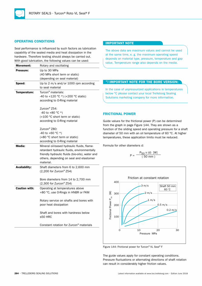
ROTARY SEALS · Turcon®Roto VL Seal®F
284 • TRELLEBORG SEALING SOLUTIONS Latest information available at www.tss.trelleborg.com • Edition June 2018
OPERATING CONDITIONS
Seal performance is influenced by such factors as lubrication capability of the sealed media and heat dissipation in the hardware. Therefore testing should always be carried out.With good lubrication, the following values can be used:
Movement: Rotary and oscillating
Pressure: Up to 30 MPa (40 MPa short term or static) (depending on seal material)
Speed: Up to 2 m/s and/or 1000 rpm according to seal material
Temperature: Turcon®materials: -40 to +120 °C *) (+200 °C static) according to O-Ring material Zurcon®Z54: -40 to +80 °C *) (+100 °C short term or static) according to O-Ring material Zurcon®Z80: -40 to +60 °C *) (+80 °C short term or static) according to O-Ring material
Media: Mineral oil-based hydraulic fluids, flame-retardant hydraulic fluids, environmentally friendly hydraulic fluids (bio-oils), water and others, depending on seal and elastomer material.
Availability: Shaft diameters from 6 to 2,600 mm (2,200 for Zurcon®Z54) Bore diameters from 14 to 2,700 mm (2,300 for Zurcon®Z54)
Caution with: Operating at temperatures above +80 °C, use O-Rings in HNBR or FKM Rotary service on shafts and bores with poor heat dissipation Shaft and bores with hardness below s50 HRC Constant rotation for Zurcon®materials
IMPORTANT NOTE
The above data are maximum values and cannot be used at the same time, e. g. the maximum operating speed depends on material type, pressure, temperature and gap value. Temperature range also depends on the media.
*) IMPORTANT NOTE FOR THE BORE VERSION:
In the case of unpressurized applications in temperatures below °C please contact your local Trelleborg Sealing Solutions marketing company for more information.
FRICTIONAL POWER
Guide values for the frictional power (P) can be determined from the graph in page Figure 144. They are shown as a function of the sliding speed and operating pressure for a shaft diameter of 50 mm with an oil temperature of 60 °C. At higher temperatures, these application limits must be reduced.
Formula for other diameters d:
P = P50 x (d) [W]
( 50 mm )
Fric
tiona
l Pow
er P
50 (W
)
Friction at constant rotation
0
100
200
300
400
10Pressure MPa
20 30
Shaft 50 mm60 ºC
3 m/s
1 m/s
0.2 m/s
2 m/s
0.5 m/s
Figure 144: Frictional power for Turcon®VL Seal®F
The guide values apply for constant operating conditions. Pressure fluctuations or alternating directions of shaft rotation can result in considerably higher friction values.
Turcon®Roto VL Seal®F
TRELLEBORG SEALING SOLUTIONS • 285Latest information available at www.tss.trelleborg.com • Edition June 2018
INSTALLATION INSTRUCTIONS
Roto VL Seal®F is installed according to information at page 309.
O-RING SIZE
O-Rings for Roto VL Seal®F are selected to suit the groove diameter:
For shaft seals the O-Ring should have OD equal to or smaller than groove diameter, for bore seals the O-Ring should have ID equal to or smaller than groove diameter.
RECOMMENDED MATERIALS
The following material combinations have proven effective for rotary applications:
Turcon®Roto VL Seal®F in Turcon®T40All-round material choice in oil hydraulics, water and other fluids with limited lubrication:
O-Ring: NBR 70 Shore A N
FKM 70 Shore A V
HNBR 70 Shore A H
Set code: T40N, T40V or T40H
Turcon®Roto VL Seal®F in Turcon®in M15 Material with high sealing effect for light to medium applications in fluids with good lubrication:
O-Ring: NBR 70 Shore A N
FKM 70 Shore A V
HNBR 70 Shore A H
Set code: M15N, M15V or M15H
Applications where high resistance to abrasive wear is required Zurcon®Z54 and Z80 are recommended.
Z54 and Z80 are for slow turning motion and not for constant rotation.
For specific applications other Turcon®and Zurcon®materials are available.
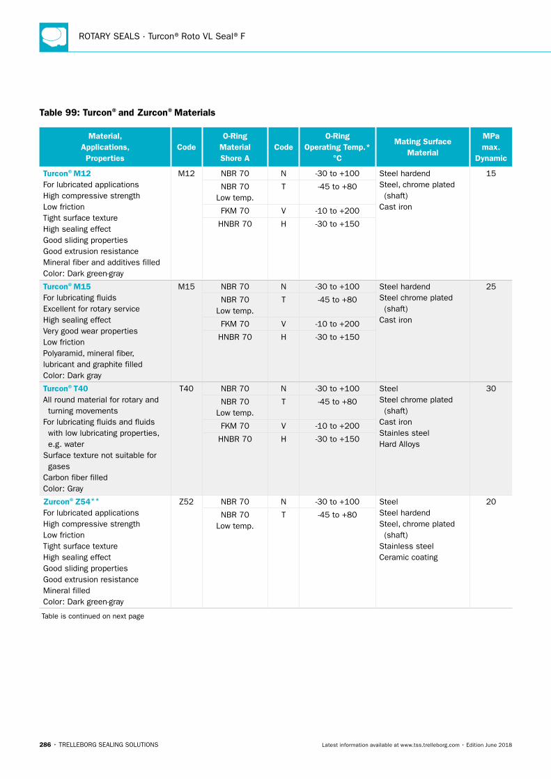
ROTARY SEALS · Turcon®Roto VL Seal®F
286 • TRELLEBORG SEALING SOLUTIONS Latest information available at www.tss.trelleborg.com • Edition June 2018
Table 99: Turcon®and Zurcon®Materials
Material, Applications, Properties
CodeO-Ring
Material Shore A
CodeO-Ring
Operating Temp.* °C
Mating Surface Material
MPa max.
Dynamic
Turcon®M12For lubricated applicationsHigh compressive strengthLow frictionTight surface textureHigh sealing effectGood sliding propertiesGood extrusion resistanceMineral fiber and additives filledColor: Dark green-gray
M12 NBR 70 N -30 to +100 Steel hardendSteel, chrome plated (shaft)Cast iron
15
NBR 70 Low temp.
T -45 to +80
FKM 70 V -10 to +200
HNBR 70 H -30 to +150
Turcon®M15For lubricating fluidsExcellent for rotary serviceHigh sealing effectVery good wear propertiesLow frictionPolyaramid, mineral fiber, lubricant and graphite filledColor: Dark gray
M15 NBR 70 N -30 to +100 Steel hardendSteel chrome plated (shaft)Cast iron
25
NBR 70 Low temp.
T -45 to +80
FKM 70 V -10 to +200
HNBR 70 H -30 to +150
Turcon®T40All round material for rotary and turning movementsFor lubricating fluids and fluids with low lubricating properties, e.g. waterSurface texture not suitable for gasesCarbon fiber filledColor: Gray
T40 NBR 70 N -30 to +100 SteelSteel chrome plated (shaft)Cast ironStainles steelHard Alloys
30
NBR 70 Low temp.
T -45 to +80
FKM 70 V -10 to +200
HNBR 70 H -30 to +150
Zurcon®Z54**
For lubricated applicationsHigh compressive strengthLow frictionTight surface textureHigh sealing effectGood sliding propertiesGood extrusion resistanceMineral filledColor: Dark green-gray
Z52 NBR 70 N -30 to +100 SteelSteel hardendSteel, chrome plated (shaft)Stainless steelCeramic coating
20
NBR 70 Low temp.
T -45 to +80
Table is continued on next page
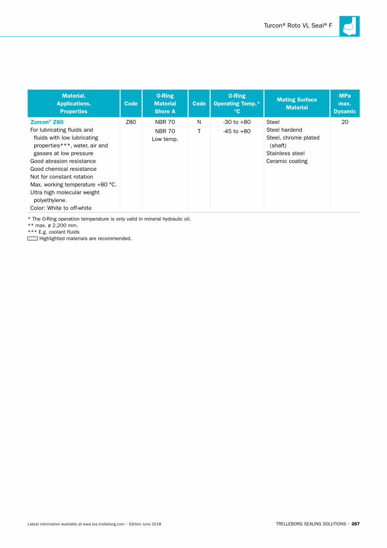
Turcon®Roto VL Seal®F
TRELLEBORG SEALING SOLUTIONS • 287Latest information available at www.tss.trelleborg.com • Edition June 2018
Material, Applications, Properties
CodeO-Ring
Material Shore A
CodeO-Ring
Operating Temp.* °C
Mating Surface Material
MPa max.
Dynamic
Zurcon®Z80For lubricating fluids and fluids with low lubricating properties***, water, air and gasses at low pressureGood abrasion resistanceGood chemical resistanceNot for constant rotationMax. working temperature +80 °C.Ultra high molecular weight polyethylene.Color: White to off-white
Z80 NBR 70 N -30 to +80 SteelSteel hardendSteel, chrome plated (shaft)Stainless steelCeramic coating
20
NBR 70 Low temp.
T -45 to +80
* The O-Ring operation temperature is only valid in mineral hydraulic oil. ** max. ø 2,200 mm. *** E.g. coolant fluids
Highlighted materials are recommended.
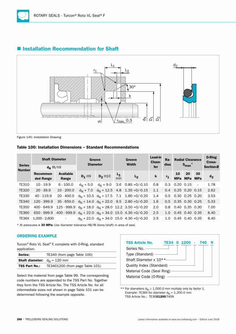
ROTARY SEALS · Turcon®Roto VL Seal®F
288 • TRELLEBORG SEALING SOLUTIONS Latest information available at www.tss.trelleborg.com • Edition June 2018
� Installation Recommendation for Shaft
D1
D2
d N
L1
rmax. 0.3
r1
30°
L2
kS
d2
Figure 145: Installation Drawing
Table 100: Installation Dimensions – Standard Recommendations
Series Number
Shaft Diameter Groove Diameter
Groove Width
Lead-in Cham-
fer
Ra-dius
Radial ClearanceSmax*
O-Ring Cross-
Section-ØdN f8/h9
Recommen-ded Range
Available Range
D1 H9 D2 H10L1 min
L2 k r110
MPa20
MPa30
MPad2
TE310 10 - 19.9 6 - 100.0 dN + 5.0 dN + 9.0 3.6 0.85 +0/-0.10 0.8 0.3 0.20 0.15 - 1.78
TE320 20 - 39.9 10 - 200.0 dN + 7.0 dN + 12.5 4.8 1.35 +0/-0.15 1.1 0.4 0.25 0.20 0.15 2.62
TE330 40 - 119.9 20 - 400.0 dN + 10.5 dN + 17.5 7.1 1.80 +0/-0.20 1.4 0.5 0.30 0.25 0.20 3.53
TE340 120 - 399.9 35 - 650.0 dN + 14.0 dN + 22.0 9.5 2.80 +0/-0.20 1.6 0.5 0.35 0.30 0.25 5.33
TE350 400 - 649.9 125 - 999.9 dN + 18.0 dN + 28.0 12.2 3.50 +0/-0.20 2.0 0.8 0.40 0.35 0.30 7.00
TE360 650 - 999.9 400 - 999.9 dN + 22.0 dN + 34.0 15.0 4.30 +0/-0.20 2.5 1.0 0.45 0.40 0.35 8.40
TE36X 1,000 - 2,600 - dN + 22.0 dN + 34.0 15.0 4.30 +0/-0.20 2.5 1.0 0.45 0.40 0.35 8.40
* At pressures > 30 MPa: Use diameter tolerance H8/f8 (bore/shaft) in area of seal.
ORDERING EXAMPLE
Turcon®Roto VL Seal®F, complete with O-Ring, standard application:
Series: TE340 (from page Table 100)
Shaft diameter: dN = 120 mm
TSS Part No.: TE3401200 (from page Table 101)
Select the material from page Table 99. The corresponding code numbers are appended to the TSS Part No. Together they form the TSS Article No. The TSS Article No. for all intermediate sizes not shown in page Table 101 can be determined following the example opposite.
TSS Article No.
Series No.Type (Standard)Shaft Diameter x 10**Quality Index (Standard)Material Code (Seal Ring)Material Code (O-Ring)
-TE34 0 1200 T40 N
** For diameters dN ≥ 1,000.0 mm multiply only by factor 1. Example: TE36X for diameter dN = 1,200.0 mm TSS Article No.: TE36X1200-T40N
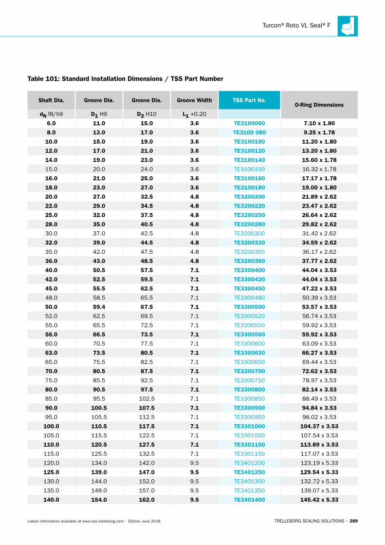
Turcon®Roto VL Seal®F
TRELLEBORG SEALING SOLUTIONS • 289Latest information available at www.tss.trelleborg.com • Edition June 2018
Shaft Dia. Groove Dia. Groove Dia. Groove Width TSS Part No.O-Ring Dimensions
dN f8/h9 D1 H9 D2 H10 L1 +0.20
6.0 11.0 15.0 3.6 TE3100060 7.10 x 1.80
8.0 13.0 17.0 3.6 TE3100 080 9.25 x 1.78
10.0 15.0 19.0 3.6 TE3100100 11.20 x 1.80
12.0 17.0 21.0 3.6 TE3100120 13.20 x 1.80
14.0 19.0 23.0 3.6 TE3100140 15.60 x 1.78
15.0 20.0 24.0 3.6 TE3100150 16.32 x 1.78
16.0 21.0 25.0 3.6 TE3100160 17.17 x 1.78
18.0 23.0 27.0 3.6 TE3100180 19.00 x 1.80
20.0 27.0 32.5 4.8 TE3200200 21.89 x 2.62
22.0 29.0 34.5 4.8 TE3200220 23.47 x 2.62
25.0 32.0 37.5 4.8 TE3200250 26.64 x 2.62
28.0 35.0 40.5 4.8 TE3200280 29.82 x 2.62
30.0 37.0 42.5 4.8 TE3200300 31.42 x 2.62
32.0 39.0 44.5 4.8 TE3200320 34.59 x 2.62
35.0 42.0 47.5 4.8 TE3200350 36.17 x 2.62
36.0 43.0 48.5 4.8 TE3200360 37.77 x 2.62
40.0 50.5 57.5 7.1 TE3300400 44.04 x 3.53
42.0 52.5 59.5 7.1 TE3300420 44.04 x 3.53
45.0 55.5 62.5 7.1 TE3300450 47.22 x 3.53
48.0 58.5 65.5 7.1 TE3300480 50.39 x 3.53
50.0 59.4 67.5 7.1 TE3300500 53.57 x 3.53
52.0 62.5 69.5 7.1 TE3300520 56.74 x 3.53
55.0 65.5 72.5 7.1 TE3300550 59.92 x 3.53
56.0 66.5 73.5 7.1 TE3300560 59.92 x 3.53
60.0 70.5 77.5 7.1 TE3300600 63.09 x 3.53
63.0 73.5 80.5 7.1 TE3300630 66.27 x 3.53
65.0 75.5 82.5 7.1 TE3300650 69.44 x 3.53
70.0 80.5 87.5 7.1 TE3300700 72.62 x 3.53
75.0 85.5 92.5 7.1 TE3300750 78.97 x 3.53
80.0 90.5 97.5 7.1 TE3300800 82.14 x 3.53
85.0 95.5 102.5 7.1 TE3300850 88.49 x 3.53
90.0 100.5 107.5 7.1 TE3300900 94.84 x 3.53
95.0 105.5 112.5 7.1 TE3300950 98.02 x 3.53
100.0 110.5 117.5 7.1 TE3301000 104.37 x 3.53
105.0 115.5 122.5 7.1 TE3301050 107.54 x 3.53
110.0 120.5 127.5 7.1 TE3301100 113.89 x 3.53
115.0 125.5 132.5 7.1 TE3301150 117.07 x 3.53
120.0 134.0 142.0 9.5 TE3401200 123.19 x 5.33
125.0 139.0 147.0 9.5 TE3401250 129.54 x 5.33
130.0 144.0 152.0 9.5 TE3401300 132.72 x 5.33
135.0 149.0 157.0 9.5 TE3401350 139.07 x 5.33
140.0 154.0 162.0 9.5 TE3401400 145.42 x 5.33
Table 101: Standard Installation Dimensions / TSS Part Number
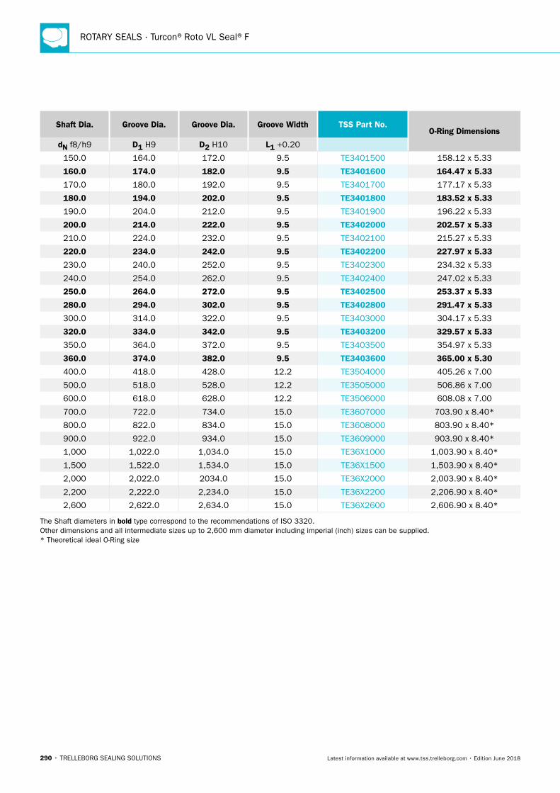
ROTARY SEALS · Turcon®Roto VL Seal®F
290 • TRELLEBORG SEALING SOLUTIONS Latest information available at www.tss.trelleborg.com • Edition June 2018
Shaft Dia. Groove Dia. Groove Dia. Groove Width TSS Part No.O-Ring Dimensions
dN f8/h9 D1 H9 D2 H10 L1 +0.20
150.0 164.0 172.0 9.5 TE3401500 158.12 x 5.33
160.0 174.0 182.0 9.5 TE3401600 164.47 x 5.33
170.0 180.0 192.0 9.5 TE3401700 177.17 x 5.33
180.0 194.0 202.0 9.5 TE3401800 183.52 x 5.33
190.0 204.0 212.0 9.5 TE3401900 196.22 x 5.33
200.0 214.0 222.0 9.5 TE3402000 202.57 x 5.33
210.0 224.0 232.0 9.5 TE3402100 215.27 x 5.33
220.0 234.0 242.0 9.5 TE3402200 227.97 x 5.33
230.0 240.0 252.0 9.5 TE3402300 234.32 x 5.33
240.0 254.0 262.0 9.5 TE3402400 247.02 x 5.33
250.0 264.0 272.0 9.5 TE3402500 253.37 x 5.33
280.0 294.0 302.0 9.5 TE3402800 291.47 x 5.33
300.0 314.0 322.0 9.5 TE3403000 304.17 x 5.33
320.0 334.0 342.0 9.5 TE3403200 329.57 x 5.33
350.0 364.0 372.0 9.5 TE3403500 354.97 x 5.33
360.0 374.0 382.0 9.5 TE3403600 365.00 x 5.30
400.0 418.0 428.0 12.2 TE3504000 405.26 x 7.00
500.0 518.0 528.0 12.2 TE3505000 506.86 x 7.00
600.0 618.0 628.0 12.2 TE3506000 608.08 x 7.00
700.0 722.0 734.0 15.0 TE3607000 703.90 x 8.40*
800.0 822.0 834.0 15.0 TE3608000 803.90 x 8.40*
900.0 922.0 934.0 15.0 TE3609000 903.90 x 8.40*
1,000 1,022.0 1,034.0 15.0 TE36X1000 1,003.90 x 8.40*
1,500 1,522.0 1,534.0 15.0 TE36X1500 1,503.90 x 8.40*
2,000 2,022.0 2034.0 15.0 TE36X2000 2,003.90 x 8.40*
2,200 2,222.0 2,234.0 15.0 TE36X2200 2,206.90 x 8.40*
2,600 2,622.0 2,634.0 15.0 TE36X2600 2,606.90 x 8.40*
The Shaft diameters in bold type correspond to the recommendations of ISO 3320. Other dimensions and all intermediate sizes up to 2,600 mm diameter including imperial (inch) sizes can be supplied. * Theoretical ideal O-Ring size
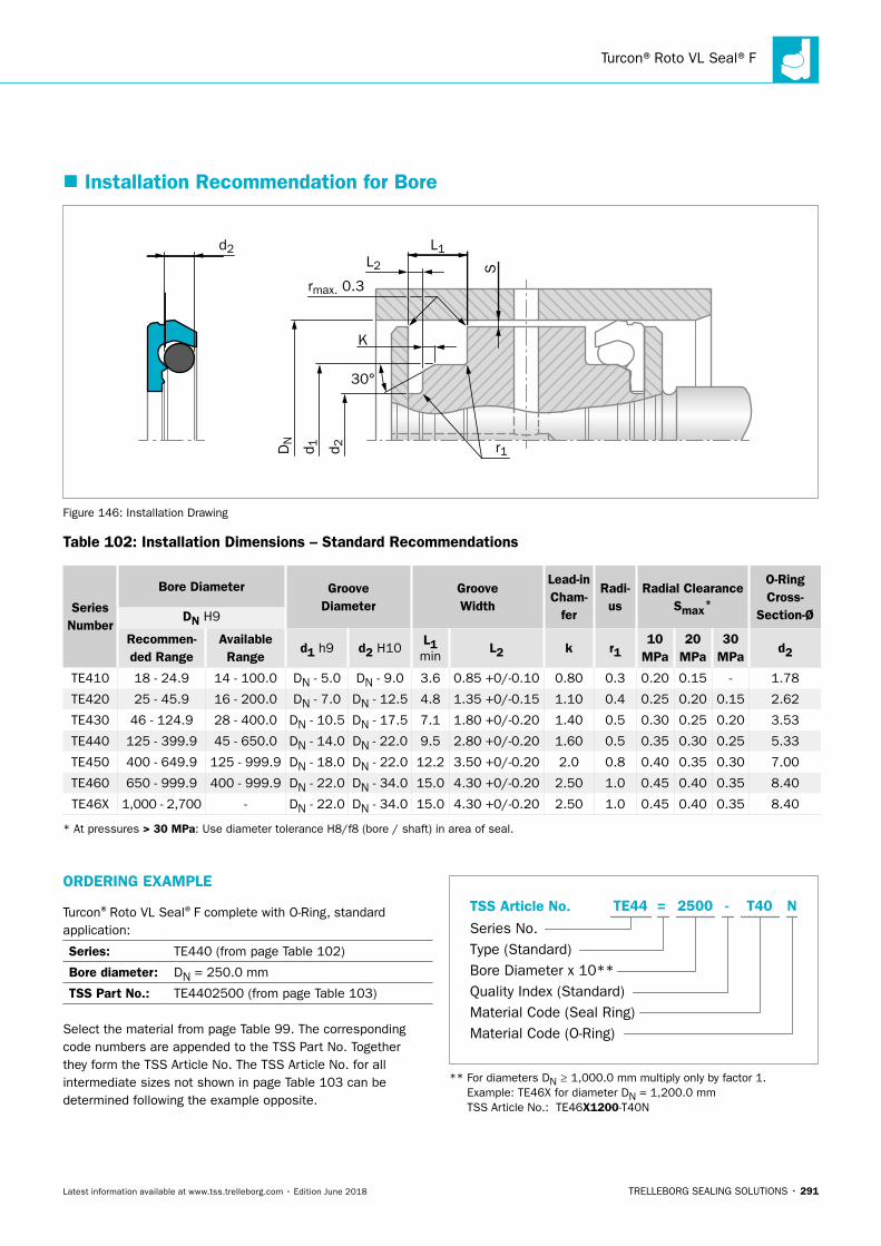
Turcon®Roto VL Seal®F
TRELLEBORG SEALING SOLUTIONS • 291Latest information available at www.tss.trelleborg.com • Edition June 2018
� Installation Recommendation for Bore
S
L1L2
rmax. 0.3D
N
d 1 d 2
30°
K
r1
d2
Figure 146: Installation Drawing
Table 102: Installation Dimensions – Standard Recommendations
Series Number
Bore Diameter Groove Diameter
Groove Width
Lead-in Cham-
fer
Radi-us
Radial ClearanceSmax*
O-Ring Cross-
Section-ØDN H9
Recommen-ded Range
Available Range
d1 h9 d2 H10L1 min
L2 k r110
MPa20
MPa30
MPad2
TE410 18 - 24.9 14 - 100.0 DN - 5.0 DN - 9.0 3.6 0.85 +0/-0.10 0.80 0.3 0.20 0.15 - 1.78
TE420 25 - 45.9 16 - 200.0 DN - 7.0 DN - 12.5 4.8 1.35 +0/-0.15 1.10 0.4 0.25 0.20 0.15 2.62
TE430 46 - 124.9 28 - 400.0 DN - 10.5 DN - 17.5 7.1 1.80 +0/-0.20 1.40 0.5 0.30 0.25 0.20 3.53
TE440 125 - 399.9 45 - 650.0 DN - 14.0 DN - 22.0 9.5 2.80 +0/-0.20 1.60 0.5 0.35 0.30 0.25 5.33
TE450 400 - 649.9 125 - 999.9 DN - 18.0 DN - 22.0 12.2 3.50 +0/-0.20 2.0 0.8 0.40 0.35 0.30 7.00
TE460 650 - 999.9 400 - 999.9 DN - 22.0 DN - 34.0 15.0 4.30 +0/-0.20 2.50 1.0 0.45 0.40 0.35 8.40
TE46X 1,000 - 2,700 - DN - 22.0 DN - 34.0 15.0 4.30 +0/-0.20 2.50 1.0 0.45 0.40 0.35 8.40
* At pressures > 30 MPa: Use diameter tolerance H8/f8 (bore / shaft) in area of seal.
ORDERING EXAMPLE
Turcon®Roto VL Seal®F complete with O-Ring, standard application:
Series: TE440 (from page Table 102)
Bore diameter: DN = 250.0 mm
TSS Part No.: TE4402500 (from page Table 103)
Select the material from page Table 99. The corresponding code numbers are appended to the TSS Part No. Together they form the TSS Article No. The TSS Article No. for all intermediate sizes not shown in page Table 103 can be determined following the example opposite.
TSS Article No.
Series No.Type (Standard)Bore Diameter x 10**Quality Index (Standard)Material Code (Seal Ring)Material Code (O-Ring)
-TE44 = 2500 T40 N
** For diameters DN ≥ 1,000.0 mm multiply only by factor 1. Example: TE46X for diameter DN = 1,200.0 mm TSS Article No.: TE46X1200-T40N
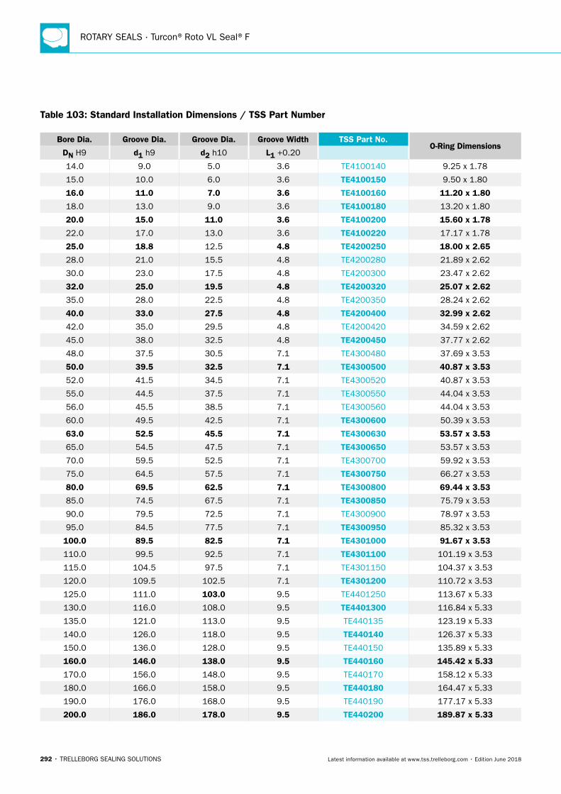
ROTARY SEALS · Turcon®Roto VL Seal®F
292 • TRELLEBORG SEALING SOLUTIONS Latest information available at www.tss.trelleborg.com • Edition June 2018
Table 103: Standard Installation Dimensions / TSS Part Number
Bore Dia. Groove Dia. Groove Dia. Groove Width TSS Part No.O-Ring Dimensions
DN H9 d1 h9 d2 h10 L1 +0.20
14.0 9.0 5.0 3.6 TE4100140 9.25 x 1.78
15.0 10.0 6.0 3.6 TE4100150 9.50 x 1.80
16.0 11.0 7.0 3.6 TE4100160 11.20 x 1.80
18.0 13.0 9.0 3.6 TE4100180 13.20 x 1.80
20.0 15.0 11.0 3.6 TE4100200 15.60 x 1.78
22.0 17.0 13.0 3.6 TE4100220 17.17 x 1.78
25.0 18.8 12.5 4.8 TE4200250 18.00 x 2.65
28.0 21.0 15.5 4.8 TE4200280 21.89 x 2.62
30.0 23.0 17.5 4.8 TE4200300 23.47 x 2.62
32.0 25.0 19.5 4.8 TE4200320 25.07 x 2.62
35.0 28.0 22.5 4.8 TE4200350 28.24 x 2.62
40.0 33.0 27.5 4.8 TE4200400 32.99 x 2.62
42.0 35.0 29.5 4.8 TE4200420 34.59 x 2.62
45.0 38.0 32.5 4.8 TE4200450 37.77 x 2.62
48.0 37.5 30.5 7.1 TE4300480 37.69 x 3.53
50.0 39.5 32.5 7.1 TE4300500 40.87 x 3.53
52.0 41.5 34.5 7.1 TE4300520 40.87 x 3.53
55.0 44.5 37.5 7.1 TE4300550 44.04 x 3.53
56.0 45.5 38.5 7.1 TE4300560 44.04 x 3.53
60.0 49.5 42.5 7.1 TE4300600 50.39 x 3.53
63.0 52.5 45.5 7.1 TE4300630 53.57 x 3.53
65.0 54.5 47.5 7.1 TE4300650 53.57 x 3.53
70.0 59.5 52.5 7.1 TE4300700 59.92 x 3.53
75.0 64.5 57.5 7.1 TE4300750 66.27 x 3.53
80.0 69.5 62.5 7.1 TE4300800 69.44 x 3.53
85.0 74.5 67.5 7.1 TE4300850 75.79 x 3.53
90.0 79.5 72.5 7.1 TE4300900 78.97 x 3.53
95.0 84.5 77.5 7.1 TE4300950 85.32 x 3.53
100.0 89.5 82.5 7.1 TE4301000 91.67 x 3.53
110.0 99.5 92.5 7.1 TE4301100 101.19 x 3.53
115.0 104.5 97.5 7.1 TE4301150 104.37 x 3.53
120.0 109.5 102.5 7.1 TE4301200 110.72 x 3.53
125.0 111.0 103.0 9.5 TE4401250 113.67 x 5.33
130.0 116.0 108.0 9.5 TE4401300 116.84 x 5.33
135.0 121.0 113.0 9.5 TE440135 123.19 x 5.33
140.0 126.0 118.0 9.5 TE440140 126.37 x 5.33
150.0 136.0 128.0 9.5 TE440150 135.89 x 5.33
160.0 146.0 138.0 9.5 TE440160 145.42 x 5.33
170.0 156.0 148.0 9.5 TE440170 158.12 x 5.33
180.0 166.0 158.0 9.5 TE440180 164.47 x 5.33
190.0 176.0 168.0 9.5 TE440190 177.17 x 5.33
200.0 186.0 178.0 9.5 TE440200 189.87 x 5.33
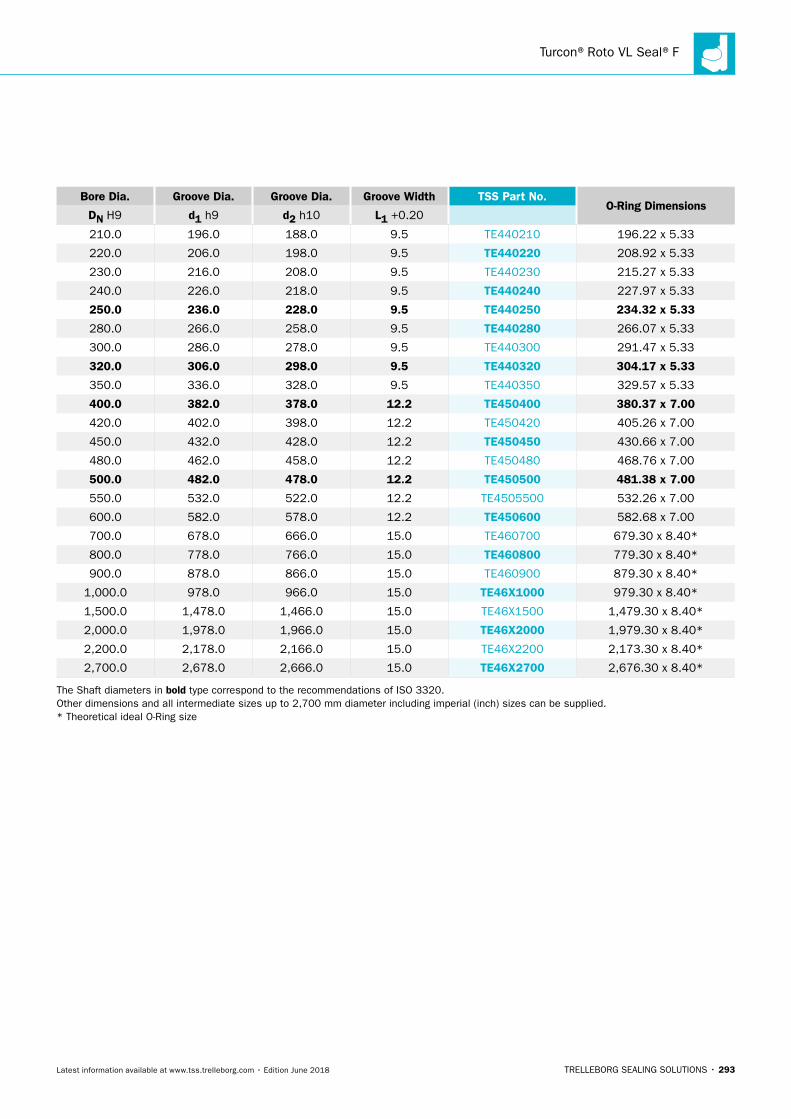
Turcon®Roto VL Seal®F
TRELLEBORG SEALING SOLUTIONS • 293Latest information available at www.tss.trelleborg.com • Edition June 2018
Bore Dia. Groove Dia. Groove Dia. Groove Width TSS Part No.O-Ring Dimensions
DN H9 d1 h9 d2 h10 L1 +0.20
210.0 196.0 188.0 9.5 TE440210 196.22 x 5.33
220.0 206.0 198.0 9.5 TE440220 208.92 x 5.33
230.0 216.0 208.0 9.5 TE440230 215.27 x 5.33
240.0 226.0 218.0 9.5 TE440240 227.97 x 5.33
250.0 236.0 228.0 9.5 TE440250 234.32 x 5.33
280.0 266.0 258.0 9.5 TE440280 266.07 x 5.33
300.0 286.0 278.0 9.5 TE440300 291.47 x 5.33
320.0 306.0 298.0 9.5 TE440320 304.17 x 5.33
350.0 336.0 328.0 9.5 TE440350 329.57 x 5.33
400.0 382.0 378.0 12.2 TE450400 380.37 x 7.00
420.0 402.0 398.0 12.2 TE450420 405.26 x 7.00
450.0 432.0 428.0 12.2 TE450450 430.66 x 7.00
480.0 462.0 458.0 12.2 TE450480 468.76 x 7.00
500.0 482.0 478.0 12.2 TE450500 481.38 x 7.00
550.0 532.0 522.0 12.2 TE4505500 532.26 x 7.00
600.0 582.0 578.0 12.2 TE450600 582.68 x 7.00
700.0 678.0 666.0 15.0 TE460700 679.30 x 8.40*
800.0 778.0 766.0 15.0 TE460800 779.30 x 8.40*
900.0 878.0 866.0 15.0 TE460900 879.30 x 8.40*
1,000.0 978.0 966.0 15.0 TE46X1000 979.30 x 8.40*
1,500.0 1,478.0 1,466.0 15.0 TE46X1500 1,479.30 x 8.40*
2,000.0 1,978.0 1,966.0 15.0 TE46X2000 1,979.30 x 8.40*
2,200.0 2,178.0 2,166.0 15.0 TE46X2200 2,173.30 x 8.40*
2,700.0 2,678.0 2,666.0 15.0 TE46X2700 2,676.30 x 8.40*
The Shaft diameters in bold type correspond to the recommendations of ISO 3320. Other dimensions and all intermediate sizes up to 2,700 mm diameter including imperial (inch) sizes can be supplied. * Theoretical ideal O-Ring size

ROTARY SEALS · Turcon®Roto VL Seal®F
294 • TRELLEBORG SEALING SOLUTIONS Latest information available at www.tss.trelleborg.com • Edition June 2018
TRELLEBORG SEALING SOLUTIONS • 295Latest information available at www.tss.trelleborg.com • Edition June 2018
Turcon®Roto VL Seal®

ROTARY SEALS · Turcon® Roto VL Seal®
296 • TRELLEBORG SEALING SOLUTIONS Latest information available at www.tss.trelleborg.com • Edition June 2018
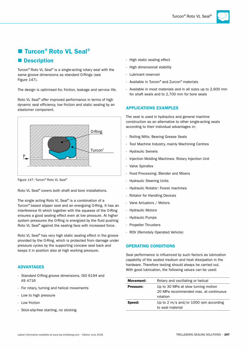
Turcon®Roto VL Seal®
TRELLEBORG SEALING SOLUTIONS • 297Latest information available at www.tss.trelleborg.com • Edition June 2018
� DescriptionTurcon®Roto VL Seal®is a single-acting rotary seal with the same groove dimensions as standard O-Rings (see Figure 147).
The design is optimised for, friction, leakage and service life.
Roto VL Seal®offer improved performance in terms of high dynamic seal efficiency, low friction and static sealing by an elastomer component.
PTurcon®
O-Ring
Figure 147: Turcon®Roto VL Seal®
Roto VL Seal®covers both shaft and bore installations.
The single acting Roto VL Seal®is a combination of a Turcon®based slipper seal and an energizing O-Ring. It has an interference fit which together with the squeeze of the O-Ring ensures a good sealing effect even at low pressure. At higher system pressures the O-Ring is energized by the fluid pushing Roto VL Seal®against the sealing face with increased force.
Roto VL Seal®has very high static sealing effect in the groove provided by the O-Ring, which is protected from damage under pressure cycles by the supporting concave seal back and keeps it in position also at high working pressure.
ADVANTAGES
- Standard O-Ring groove dimensions, ISO 6194 and AS 4716
- For rotary, turning and helical movements
- Low to high pressure
- Low friction
- Stick-slip-free starting, no sticking
- High static sealing effect
- High dimensional stability
- Lubricant reservoir
- Available in Turcon®and Zurcon®materials
- Available in most materials and in all sizes up to 2,600 mm for shaft seals and to 2,700 mm for bore seals
APPLICATIONS EXAMPLES
The seal is used in hydraulics and general machine construction as an alternative to other single-acting seals according to their individual advantages in:
- Rolling Mills: Bearing Grease Seals
- Tool Machine Industry, mainly Machining Centres
- Hydraulic Swivels
- Injection Molding Machines: Rotary Injection Unit
- Valve Spindles
- Food Processing: Blender and Mixers
- Hydraulic Steering Units
- Hydraulic Rotator: Forest machines
- Rotator for Handling Devices
- Vane Actuators / Motors
- Hydraulic Motors
- Hydraulic Pumps
- Propeller Thrusters
- ROV (Remotely Operated Vehicle)
OPERATING CONDITIONS
Seal performance is influenced by such factors as lubrication capability of the sealed medium and heat dissipation in the hardware. Therefore testing should always be carried out.With good lubrication, the following values can be used:
Movement: Rotary and oscillating or helical
Pressure: Up to 30 MPa at slow turning motion 20 MPa recommended max. at continuous rotation
Speed: Up to 2 m/s and/or 1000 rpm according to seal material
� Turcon®Roto VL Seal®
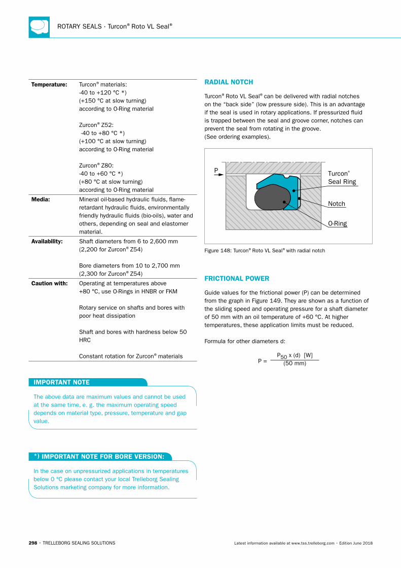
ROTARY SEALS · Turcon®Roto VL Seal®
298 • TRELLEBORG SEALING SOLUTIONS Latest information available at www.tss.trelleborg.com • Edition June 2018
Temperature: Turcon®materials: -40 to +120 °C *) (+150 °C at slow turning) according to O-Ring material Zurcon®Z52: -40 to +80 °C *) (+100 °C at slow turning) according to O-Ring material Zurcon®Z80: -40 to +60 °C *) (+80 °C at slow turning) according to O-Ring material
Media: Mineral oil-based hydraulic fluids, flame-retardant hydraulic fluids, environmentally friendly hydraulic fluids (bio-oils), water and others, depending on seal and elastomer material.
Availability: Shaft diameters from 6 to 2,600 mm (2,200 for Zurcon®Z54) Bore diameters from 10 to 2,700 mm (2,300 for Zurcon®Z54)
Caution with: Operating at temperatures above +80 °C, use O-Rings in HNBR or FKM Rotary service on shafts and bores with poor heat dissipation Shaft and bores with hardness below 50 HRC Constant rotation for Zurcon®materials
IMPORTANT NOTE
The above data are maximum values and cannot be used at the same time, e. g. the maximum operating speed depends on material type, pressure, temperature and gap value.
*) IMPORTANT NOTE FOR BORE VERSION:
In the case on unpressurized applications in temperatures below 0 °C please contact your local Trelleborg Sealing Solutions marketing company for more information.
RADIAL NOTCH
Turcon®Roto VL Seal®can be delivered with radial notches on the “back side” (low pressure side). This is an advantage if the seal is used in rotary applications. If pressurized fluid is trapped between the seal and groove corner, notches can prevent the seal from rotating in the groove. (See ordering examples).
P Turcon® Seal Ring
Notch
O-Ring
Figure 148: Turcon®Roto VL Seal®with radial notch
FRICTIONAL POWER
Guide values for the frictional power (P) can be determined from the graph in Figure 149. They are shown as a function of the sliding speed and operating pressure for a shaft diameter of 50 mm with an oil temperature of +60 °C. At higher temperatures, these application limits must be reduced.
Formula for other diameters d:
P = P50 x (d) [W]
(50 mm)
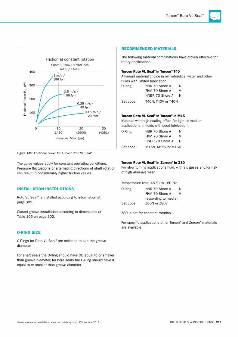
Turcon®Roto VL Seal®
TRELLEBORG SEALING SOLUTIONS • 299Latest information available at www.tss.trelleborg.com • Edition June 2018
Fric
tiona
l Pow
er P
50
(W)
Friction at constant rotation
0
100
200
300
400
10(1450) (2900) (4351)
Pressure MPa (psi)
20 30
1 m/s /196 fpm
0.5 m/s /98 fpm
0.25 m/s /49 fpm
0.15 m/s /29 fpm
Shaft 50 mm / 1.968 inch60 ºC / 140 ºF
Figure 149: Frictional power for Turcon®Roto VL Seal®
The guide values apply for constant operating conditions. Pressure fluctuations or alternating directions of shaft rotation can result in considerably higher friction values.
INSTALLATION INSTRUCTIONS
Roto VL Seal®is installed according to information at page 309.
Closed groove installation according to dimensions at Table 105 on page 302.
O-RING SIZE
O-Rings for Roto VL Seal®are selected to suit the groove diameter.
For shaft seals the O-Ring should have OD equal to or smaller than groove diameter, for bore seals the O-Ring should have ID equal to or smaller than groove diameter.
RECOMMENDED MATERIALS
The following material combinations have proven effective for rotary applications:
Turcon Roto VL Seal®in Turcon®T40All-round material choice in oil hydraulics, water and other fluids with limited lubrication:O-Ring: NBR 70 Shore A N FKM 70 Shore A V HNBR 70 Shore A H
Set code: T40N, T40V or T40H
Turcon Roto VL Seal®in Turcon®in M15Material with high sealing effect for light to medium applications in fluids with good lubrication:
O-Ring: NBR 70 Shore A N FKM 70 Shore A V HNBR 70 Shore A H
Set code: M15N, M15V or M15H
Turcon Roto VL Seal®in Zurcon®in Z80For slow turning applications fluid, with air, gases and/or risk of high abrasive wear.
Temperature limit -45 °C to +80 °C:
O-Ring: NBR 70 Shore A N FKM 70 Shore A V (according to media) Set code: Z80N or Z80V
Z80 is not for constant rotation.
For specific applications other Turcon®and Zurcon®materials are available.
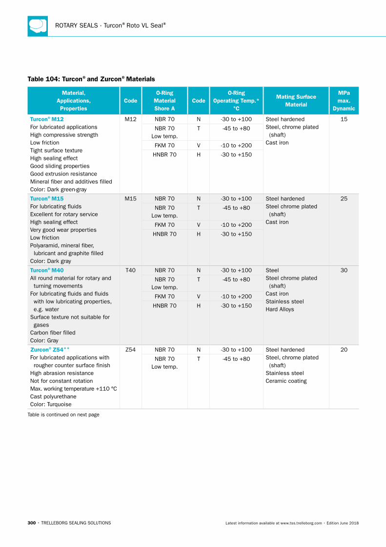
ROTARY SEALS · Turcon®Roto VL Seal®
300 • TRELLEBORG SEALING SOLUTIONS Latest information available at www.tss.trelleborg.com • Edition June 2018
Table 104: Turcon®and Zurcon®Materials
Material, Applications, Properties
CodeO-Ring
Material Shore A
CodeO-Ring
Operating Temp.* °C
Mating Surface Material
MPa max.
Dynamic
Turcon®M12For lubricated applicationsHigh compressive strengthLow frictionTight surface textureHigh sealing effectGood sliding propertiesGood extrusion resistanceMineral fiber and additives filledColor: Dark green-gray
M12 NBR 70 N -30 to +100 Steel hardenedSteel, chrome plated (shaft)Cast iron
15
NBR 70 Low temp.
T -45 to +80
FKM 70 V -10 to +200
HNBR 70 H -30 to +150
Turcon®M15For lubricating fluidsExcellent for rotary serviceHigh sealing effectVery good wear propertiesLow frictionPolyaramid, mineral fiber, lubricant and graphite filledColor: Dark gray
M15 NBR 70 N -30 to +100 Steel hardenedSteel chrome plated (shaft)Cast iron
25
NBR 70 Low temp.
T -45 to +80
FKM 70 V -10 to +200
HNBR 70 H -30 to +150
Turcon®M40All round material for rotary and turning movementsFor lubricating fluids and fluids with low lubricating properties, e.g. waterSurface texture not suitable for gasesCarbon fiber filledColor: Gray
T40 NBR 70 N -30 to +100 SteelSteel chrome plated (shaft)Cast ironStainless steelHard Alloys
30
NBR 70 Low temp.
T -45 to +80
FKM 70 V -10 to +200
HNBR 70 H -30 to +150
Zurcon®Z54**
For lubricated applications with rougher counter surface finishHigh abrasion resistanceNot for constant rotationMax. working temperature +110 °CCast polyurethaneColor: Turquoise
Z54 NBR 70 N -30 to +100 Steel hardenedSteel, chrome plated (shaft)Stainless steelCeramic coating
20
NBR 70 Low temp.
T -45 to +80
Table is continued on next page
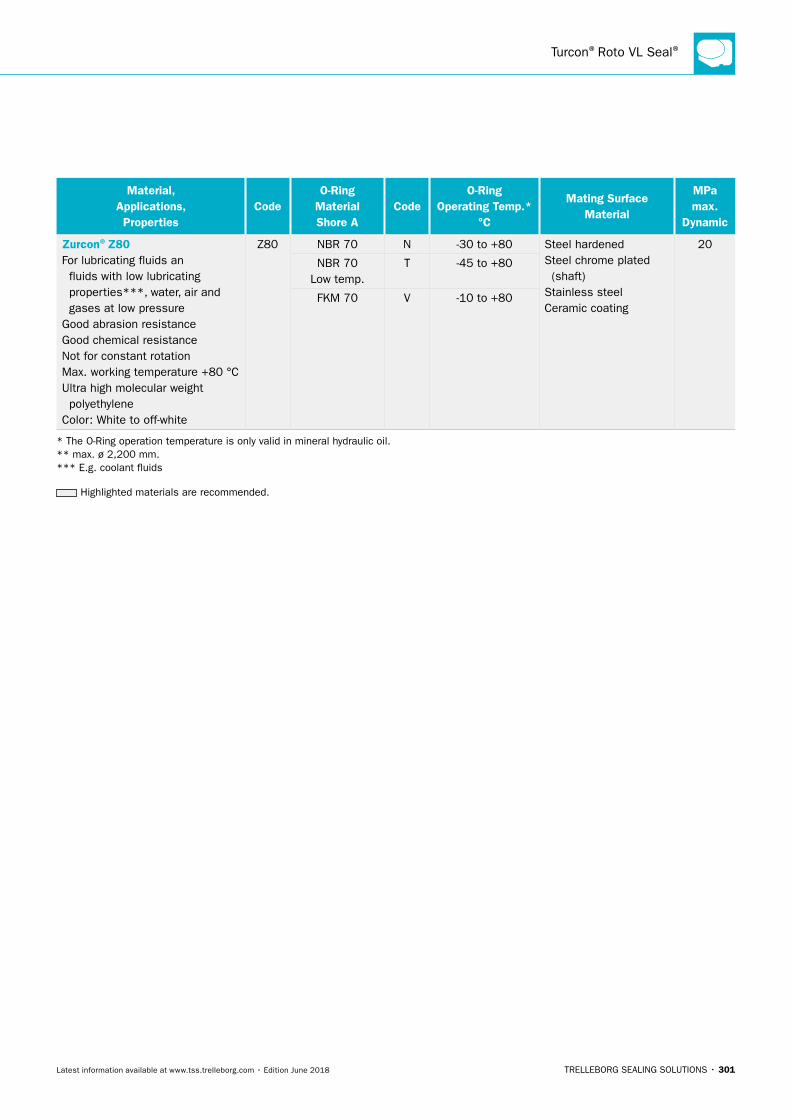
Turcon®Roto VL Seal®
TRELLEBORG SEALING SOLUTIONS • 301Latest information available at www.tss.trelleborg.com • Edition June 2018
Material, Applications, Properties
CodeO-Ring
Material Shore A
CodeO-Ring
Operating Temp.* °C
Mating Surface Material
MPa max.
Dynamic
Zurcon®Z80For lubricating fluids an fluids with low lubricating properties***, water, air and gases at low pressureGood abrasion resistanceGood chemical resistanceNot for constant rotationMax. working temperature +80 °CUltra high molecular weight polyethyleneColor: White to off-white
Z80 NBR 70 N -30 to +80 Steel hardenedSteel chrome plated (shaft)Stainless steelCeramic coating
20
NBR 70 Low temp.
T -45 to +80
FKM 70 V -10 to +80
* The O-Ring operation temperature is only valid in mineral hydraulic oil. ** max. ø 2,200 mm. *** E.g. coolant fluids
Highlighted materials are recommended.
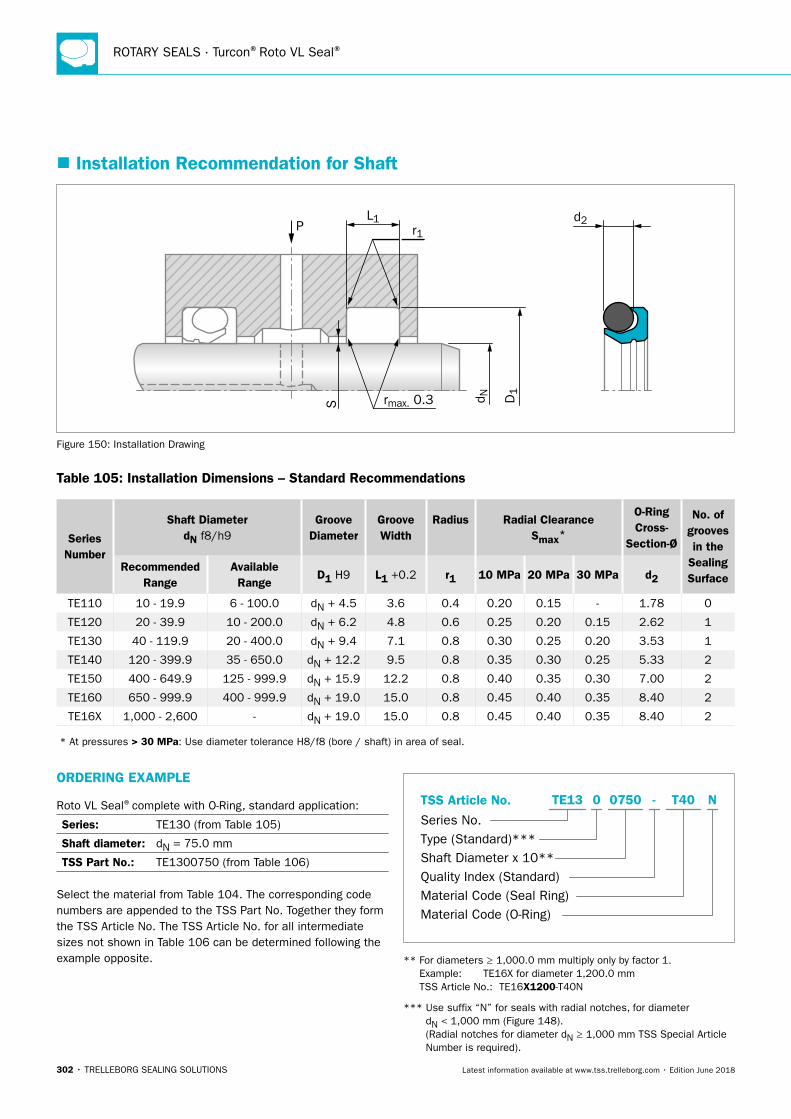
ROTARY SEALS · Turcon®Roto VL Seal®
302 • TRELLEBORG SEALING SOLUTIONS Latest information available at www.tss.trelleborg.com • Edition June 2018
� Installation Recommendation for Shaft
PL1
S rmax. 0.3
d2r1
D1
d N
Figure 150: Installation Drawing
Table 105: Installation Dimensions – Standard Recommendations
Series Number
Shaft DiameterdN f8/h9
Groove Diameter
Groove Width
Radius Radial ClearanceSmax*
O-Ring Cross-
Section-Ø
No. of grooves in the
Sealing Surface
Recommended Range
Available Range
D1 H9 L1 +0.2 r1 10 MPa 20 MPa 30 MPa d2
TE110 10 - 19.9 6 - 100.0 dN + 4.5 3.6 0.4 0.20 0.15 - 1.78 0
TE120 20 - 39.9 10 - 200.0 dN + 6.2 4.8 0.6 0.25 0.20 0.15 2.62 1
TE130 40 - 119.9 20 - 400.0 dN + 9.4 7.1 0.8 0.30 0.25 0.20 3.53 1
TE140 120 - 399.9 35 - 650.0 dN + 12.2 9.5 0.8 0.35 0.30 0.25 5.33 2
TE150 400 - 649.9 125 - 999.9 dN + 15.9 12.2 0.8 0.40 0.35 0.30 7.00 2
TE160 650 - 999.9 400 - 999.9 dN + 19.0 15.0 0.8 0.45 0.40 0.35 8.40 2
TE16X 1,000 - 2,600 - dN + 19.0 15.0 0.8 0.45 0.40 0.35 8.40 2
* At pressures > 30 MPa: Use diameter tolerance H8/f8 (bore / shaft) in area of seal.
ORDERING EXAMPLE
Roto VL Seal®complete with O-Ring, standard application:
Series: TE130 (from Table 105)
Shaft diameter: dN = 75.0 mm
TSS Part No.: TE1300750 (from Table 106)
Select the material from Table 104. The corresponding code numbers are appended to the TSS Part No. Together they form the TSS Article No. The TSS Article No. for all intermediate sizes not shown in Table 106 can be determined following the example opposite.
TSS Article No.
Series No.Type (Standard)***Shaft Diameter x 10**Quality Index (Standard)Material Code (Seal Ring)Material Code (O-Ring)
-TE13 0 0750 T40 N
** For diameters ≥ 1,000.0 mm multiply only by factor 1. Example: TE16X for diameter 1,200.0 mm TSS Article No.: TE16X1200-T40N
*** Use suffix “N” for seals with radial notches, for diameter dN < 1,000 mm (Figure 148). (Radial notches for diameter dN ≥ 1,000 mm TSS Special Article Number is required).
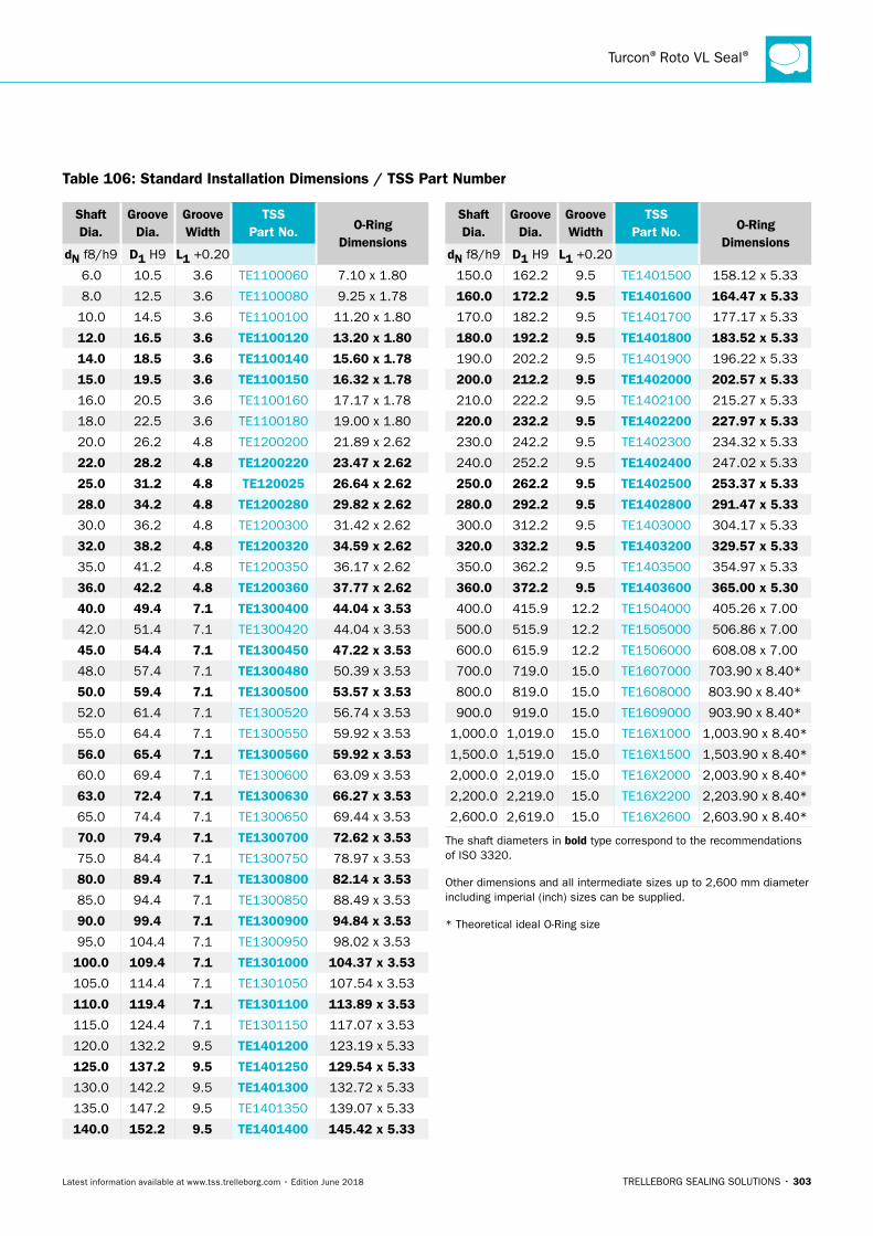
Turcon®Roto VL Seal®
TRELLEBORG SEALING SOLUTIONS • 303Latest information available at www.tss.trelleborg.com • Edition June 2018
Shaft Dia.
Groove Dia.
Groove Width
TSS Part No. O-Ring
DimensionsdN f8/h9 D1 H9 L1 +0.20
6.0 10.5 3.6 TE1100060 7.10 x 1.80
8.0 12.5 3.6 TE1100080 9.25 x 1.78
10.0 14.5 3.6 TE1100100 11.20 x 1.80
12.0 16.5 3.6 TE1100120 13.20 x 1.80
14.0 18.5 3.6 TE1100140 15.60 x 1.78
15.0 19.5 3.6 TE1100150 16.32 x 1.78
16.0 20.5 3.6 TE1100160 17.17 x 1.78
18.0 22.5 3.6 TE1100180 19.00 x 1.80
20.0 26.2 4.8 TE1200200 21.89 x 2.62
22.0 28.2 4.8 TE1200220 23.47 x 2.62
25.0 31.2 4.8 TE120025 26.64 x 2.62
28.0 34.2 4.8 TE1200280 29.82 x 2.62
30.0 36.2 4.8 TE1200300 31.42 x 2.62
32.0 38.2 4.8 TE1200320 34.59 x 2.62
35.0 41.2 4.8 TE1200350 36.17 x 2.62
36.0 42.2 4.8 TE1200360 37.77 x 2.62
40.0 49.4 7.1 TE1300400 44.04 x 3.53
42.0 51.4 7.1 TE1300420 44.04 x 3.53
45.0 54.4 7.1 TE1300450 47.22 x 3.53
48.0 57.4 7.1 TE1300480 50.39 x 3.53
50.0 59.4 7.1 TE1300500 53.57 x 3.53
52.0 61.4 7.1 TE1300520 56.74 x 3.53
55.0 64.4 7.1 TE1300550 59.92 x 3.53
56.0 65.4 7.1 TE1300560 59.92 x 3.53
60.0 69.4 7.1 TE1300600 63.09 x 3.53
63.0 72.4 7.1 TE1300630 66.27 x 3.53
65.0 74.4 7.1 TE1300650 69.44 x 3.53
70.0 79.4 7.1 TE1300700 72.62 x 3.53
75.0 84.4 7.1 TE1300750 78.97 x 3.53
80.0 89.4 7.1 TE1300800 82.14 x 3.53
85.0 94.4 7.1 TE1300850 88.49 x 3.53
90.0 99.4 7.1 TE1300900 94.84 x 3.53
95.0 104.4 7.1 TE1300950 98.02 x 3.53
100.0 109.4 7.1 TE1301000 104.37 x 3.53
105.0 114.4 7.1 TE1301050 107.54 x 3.53
110.0 119.4 7.1 TE1301100 113.89 x 3.53
115.0 124.4 7.1 TE1301150 117.07 x 3.53
120.0 132.2 9.5 TE1401200 123.19 x 5.33
125.0 137.2 9.5 TE1401250 129.54 x 5.33
130.0 142.2 9.5 TE1401300 132.72 x 5.33
135.0 147.2 9.5 TE1401350 139.07 x 5.33
140.0 152.2 9.5 TE1401400 145.42 x 5.33
Shaft Dia.
Groove Dia.
Groove Width
TSS Part No. O-Ring
DimensionsdN f8/h9 D1 H9 L1 +0.20
150.0 162.2 9.5 TE1401500 158.12 x 5.33
160.0 172.2 9.5 TE1401600 164.47 x 5.33
170.0 182.2 9.5 TE1401700 177.17 x 5.33
180.0 192.2 9.5 TE1401800 183.52 x 5.33
190.0 202.2 9.5 TE1401900 196.22 x 5.33
200.0 212.2 9.5 TE1402000 202.57 x 5.33
210.0 222.2 9.5 TE1402100 215.27 x 5.33
220.0 232.2 9.5 TE1402200 227.97 x 5.33
230.0 242.2 9.5 TE1402300 234.32 x 5.33
240.0 252.2 9.5 TE1402400 247.02 x 5.33
250.0 262.2 9.5 TE1402500 253.37 x 5.33
280.0 292.2 9.5 TE1402800 291.47 x 5.33
300.0 312.2 9.5 TE1403000 304.17 x 5.33
320.0 332.2 9.5 TE1403200 329.57 x 5.33
350.0 362.2 9.5 TE1403500 354.97 x 5.33
360.0 372.2 9.5 TE1403600 365.00 x 5.30
400.0 415.9 12.2 TE1504000 405.26 x 7.00
500.0 515.9 12.2 TE1505000 506.86 x 7.00
600.0 615.9 12.2 TE1506000 608.08 x 7.00
700.0 719.0 15.0 TE1607000 703.90 x 8.40*
800.0 819.0 15.0 TE1608000 803.90 x 8.40*
900.0 919.0 15.0 TE1609000 903.90 x 8.40*
1,000.0 1,019.0 15.0 TE16X1000 1,003.90 x 8.40*
1,500.0 1,519.0 15.0 TE16X1500 1,503.90 x 8.40*
2,000.0 2,019.0 15.0 TE16X2000 2,003.90 x 8.40*
2,200.0 2,219.0 15.0 TE16X2200 2,203.90 x 8.40*
2,600.0 2,619.0 15.0 TE16X2600 2,603.90 x 8.40*
The shaft diameters in bold type correspond to the recommendations of ISO 3320.
Other dimensions and all intermediate sizes up to 2,600 mm diameter including imperial (inch) sizes can be supplied.
* Theoretical ideal O-Ring size
Table 106: Standard Installation Dimensions / TSS Part Number
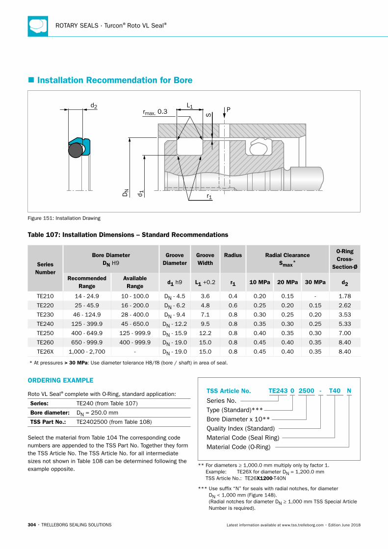
ROTARY SEALS · Turcon®Roto VL Seal®
304 • TRELLEBORG SEALING SOLUTIONS Latest information available at www.tss.trelleborg.com • Edition June 2018
� Installation Recommendation for Bore
P
S
L1rmax. 0.3
r1DN
d 1
d2
Figure 151: Installation Drawing
Table 107: Installation Dimensions – Standard Recommendations
Series Number
Bore DiameterDN H9
Groove Diameter
Groove Width
Radius Radial ClearanceSmax*
O-Ring Cross-
Section-Ø
Recommended Range
Available Range
d1 h9 L1 +0.2 r1 10 MPa 20 MPa 30 MPa d2
TE210 14 - 24.9 10 - 100.0 DN - 4.5 3.6 0.4 0.20 0.15 - 1.78
TE220 25 - 45.9 16 - 200.0 DN - 6.2 4.8 0.6 0.25 0.20 0.15 2.62
TE230 46 - 124.9 28 - 400.0 DN - 9.4 7.1 0.8 0.30 0.25 0.20 3.53
TE240 125 - 399.9 45 - 650.0 DN - 12.2 9.5 0.8 0.35 0.30 0.25 5.33
TE250 400 - 649.9 125 - 999.9 DN - 15.9 12.2 0.8 0.40 0.35 0.30 7.00
TE260 650 - 999.9 400 - 999.9 DN - 19.0 15.0 0.8 0.45 0.40 0.35 8.40
TE26X 1,000 - 2,700 - DN - 19.0 15.0 0.8 0.45 0.40 0.35 8.40
* At pressures > 30 MPa: Use diameter tolerance H8/f8 (bore / shaft) in area of seal.
ORDERING EXAMPLE
Roto VL Seal®complete with O-Ring, standard application:
Series: TE240 (from Table 107)
Bore diameter: DN = 250.0 mm
TSS Part No.: TE2402500 (from Table 108)
Select the material from Table 104 The corresponding code numbers are appended to the TSS Part No. Together they form the TSS Article No. The TSS Article No. for all intermediate sizes not shown in Table 108 can be determined following the example opposite.
TSS Article No.
Series No.Type (Standard)***Bore Diameter x 10**Quality Index (Standard)Material Code (Seal Ring)Material Code (O-Ring)
-TE243 0 2500 T40 N
** For diameters ≥ 1,000.0 mm multiply only by factor 1. Example: TE26X for diameter DN = 1,200.0 mm TSS Article No.: TE26X1200-T40N
*** Use suffix “N” for seals with radial notches, for diameter DN < 1,000 mm (Figure 148). (Radial notches for diameter DN ≥ 1,000 mm TSS Special Article Number is required).
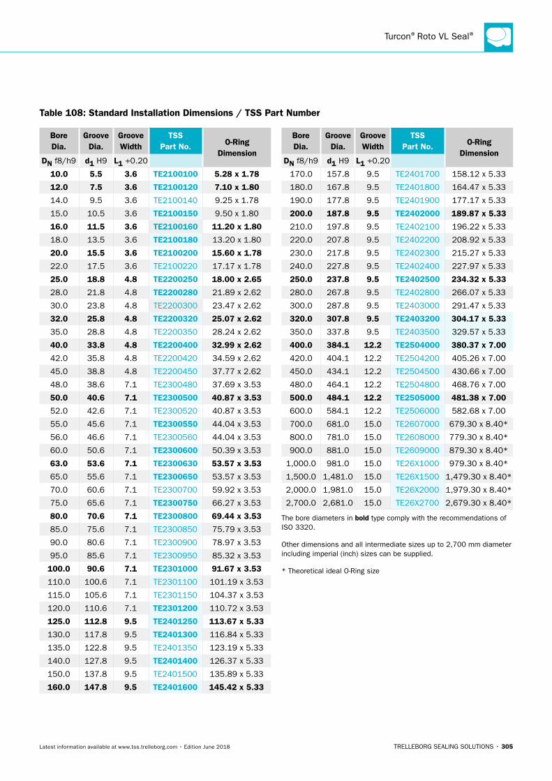
Turcon®Roto VL Seal®
TRELLEBORG SEALING SOLUTIONS • 305Latest information available at www.tss.trelleborg.com • Edition June 2018
Bore Dia.
Groove Dia.
Groove Width
TSS Part No. O-Ring
DimensionDN f8/h9 d1 H9 L1 +0.20
10.0 5.5 3.6 TE2100100 5.28 x 1.78
12.0 7.5 3.6 TE2100120 7.10 x 1.80
14.0 9.5 3.6 TE2100140 9.25 x 1.78
15.0 10.5 3.6 TE2100150 9.50 x 1.80
16.0 11.5 3.6 TE2100160 11.20 x 1.80
18.0 13.5 3.6 TE2100180 13.20 x 1.80
20.0 15.5 3.6 TE2100200 15.60 x 1.78
22.0 17.5 3.6 TE2100220 17.17 x 1.78
25.0 18.8 4.8 TE2200250 18.00 x 2.65
28.0 21.8 4.8 TE2200280 21.89 x 2.62
30.0 23.8 4.8 TE2200300 23.47 x 2.62
32.0 25.8 4.8 TE2200320 25.07 x 2.62
35.0 28.8 4.8 TE2200350 28.24 x 2.62
40.0 33.8 4.8 TE2200400 32.99 x 2.62
42.0 35.8 4.8 TE2200420 34.59 x 2.62
45.0 38.8 4.8 TE2200450 37.77 x 2.62
48.0 38.6 7.1 TE2300480 37.69 x 3.53
50.0 40.6 7.1 TE2300500 40.87 x 3.53
52.0 42.6 7.1 TE2300520 40.87 x 3.53
55.0 45.6 7.1 TE2300550 44.04 x 3.53
56.0 46.6 7.1 TE2300560 44.04 x 3.53
60.0 50.6 7.1 TE2300600 50.39 x 3.53
63.0 53.6 7.1 TE2300630 53.57 x 3.53
65.0 55.6 7.1 TE2300650 53.57 x 3.53
70.0 60.6 7.1 TE2300700 59.92 x 3.53
75.0 65.6 7.1 TE2300750 66.27 x 3.53
80.0 70.6 7.1 TE2300800 69.44 x 3.53
85.0 75.6 7.1 TE2300850 75.79 x 3.53
90.0 80.6 7.1 TE2300900 78.97 x 3.53
95.0 85.6 7.1 TE2300950 85.32 x 3.53
100.0 90.6 7.1 TE2301000 91.67 x 3.53
110.0 100.6 7.1 TE2301100 101.19 x 3.53
115.0 105.6 7.1 TE2301150 104.37 x 3.53
120.0 110.6 7.1 TE2301200 110.72 x 3.53
125.0 112.8 9.5 TE2401250 113.67 x 5.33
130.0 117.8 9.5 TE2401300 116.84 x 5.33
135.0 122.8 9.5 TE2401350 123.19 x 5.33
140.0 127.8 9.5 TE2401400 126.37 x 5.33
150.0 137.8 9.5 TE2401500 135.89 x 5.33
160.0 147.8 9.5 TE2401600 145.42 x 5.33
Bore Dia.
Groove Dia.
Groove Width
TSS Part No. O-Ring
DimensionDN f8/h9 d1 H9 L1 +0.20
170.0 157.8 9.5 TE2401700 158.12 x 5.33
180.0 167.8 9.5 TE2401800 164.47 x 5.33
190.0 177.8 9.5 TE2401900 177.17 x 5.33
200.0 187.8 9.5 TE2402000 189.87 x 5.33
210.0 197.8 9.5 TE2402100 196.22 x 5.33
220.0 207.8 9.5 TE2402200 208.92 x 5.33
230.0 217.8 9.5 TE2402300 215.27 x 5.33
240.0 227.8 9.5 TE2402400 227.97 x 5.33
250.0 237.8 9.5 TE2402500 234.32 x 5.33
280.0 267.8 9.5 TE2402800 266.07 x 5.33
300.0 287.8 9.5 TE2403000 291.47 x 5.33
320.0 307.8 9.5 TE2403200 304.17 x 5.33
350.0 337.8 9.5 TE2403500 329.57 x 5.33
400.0 384.1 12.2 TE2504000 380.37 x 7.00
420.0 404.1 12.2 TE2504200 405.26 x 7.00
450.0 434.1 12.2 TE2504500 430.66 x 7.00
480.0 464.1 12.2 TE2504800 468.76 x 7.00
500.0 484.1 12.2 TE2505000 481.38 x 7.00
600.0 584.1 12.2 TE2506000 582.68 x 7.00
700.0 681.0 15.0 TE2607000 679.30 x 8.40*
800.0 781.0 15.0 TE2608000 779.30 x 8.40*
900.0 881.0 15.0 TE2609000 879.30 x 8.40*
1,000.0 981.0 15.0 TE26X1000 979.30 x 8.40*
1,500.0 1,481.0 15.0 TE26X1500 1,479.30 x 8.40*
2,000.0 1,981.0 15.0 TE26X2000 1,979.30 x 8.40*
2,700.0 2,681.0 15.0 TE26X2700 2,679.30 x 8.40*
The bore diameters in bold type comply with the recommendations of ISO 3320.
Other dimensions and all intermediate sizes up to 2,700 mm diameter including imperial (inch) sizes can be supplied.
* Theoretical ideal O-Ring size
Table 108: Standard Installation Dimensions / TSS Part Number

ROTARY SEALS · Turcon®Roto VL Seal®
306 • TRELLEBORG SEALING SOLUTIONS Latest information available at www.tss.trelleborg.com • Edition June 2018
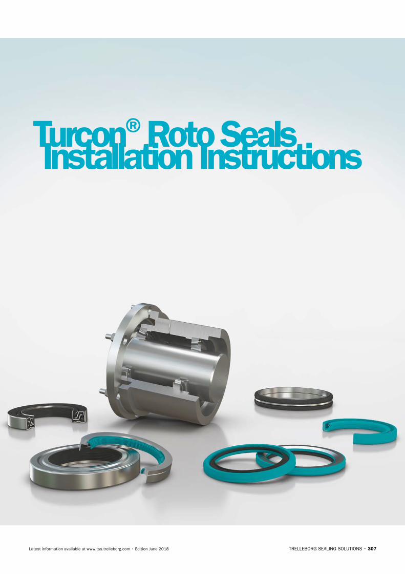
TRELLEBORG SEALING SOLUTIONS • 307Latest information available at www.tss.trelleborg.com • Edition June 2018
Turcon®Roto SealsInstallation Instructions

ROTARY SEALS · Turcon®Roto Seals – Installation Instructions
308 • TRELLEBORG SEALING SOLUTIONS Latest information available at www.tss.trelleborg.com • Edition June 2018
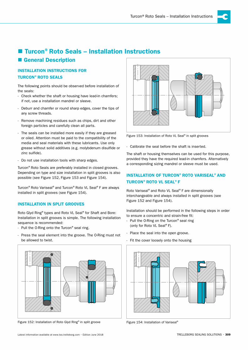
Turcon®Roto Seals – Installation Instructions
TRELLEBORG SEALING SOLUTIONS • 309Latest information available at www.tss.trelleborg.com • Edition June 2018
� General Description
INSTALLATION INSTRUCTIONS FOR
TURCON®ROTO SEALS
The following points should be observed before installation of the seals: - Check whether the shaft or housing have lead-in chamfers;
if not, use a installation mandrel or sleeve.
- Deburr and chamfer or round sharp edges, cover the tips of any screw threads.
- Remove machining residues such as chips, dirt and other foreign particles and carefully clean all parts.
- The seals can be installed more easily if they are greased or oiled. Attention must be paid to the compatibility of the media and seal materials with these lubricants. Use only grease without solid additives (e.g. molybdenum disulfide or zinc sulfide).
- Do not use installation tools with sharp edges.
Turcon®Roto Seals are preferably installed in closed grooves. Depending on type and size installation in split grooves is also possible (see Figure 152, Figure 153 and Figure 154).
Turcon®Roto Variseal®and Turcon®Roto VL Seal®F are always installed in split grooves (see Figure 154).
INSTALLATION IN SPLIT GROOVES
Roto Glyd Ring®types and Roto VL Seal®for Shaft and Bore:Installation in split grooves is simple. The following installation sequence is recommended: - Pull the O-Ring onto the Turcon®seal ring.
- Press the seal element into the groove. The O-Ring must not be allowed to twist.
Figure 152: Installation of Roto Glyd Ring®in split groove
Figure 153: Installation of Roto VL Seal®in split grooves
- Calibrate the seal before the shaft is inserted.
The shaft or housing themselves can be used for this purpose, provided they have the required lead-in chamfers. Alternatively a corresponding sizing mandrel or sleeve must be used.
INSTALLATION OF TURCON®ROTO VARISEAL®AND
TURCON®ROTO VL SEAL®F
Roto Variseal®and Roto VL Seal®F are dimensionally interchangeable and always installed in split grooves (see Figure 152 and Figure 154).
Installation should be performed in the following steps in order to ensure a concentric and strain-free fit: - Pull the O-Ring on the Turcon®seal ring
(only for Roto VL Seal®F).
- Place the seal into the open groove.
- Fit the cover loosely onto the housing
Figure 154: Installation of Variseal®
� Turcon®Roto Seals – Installation Instructions
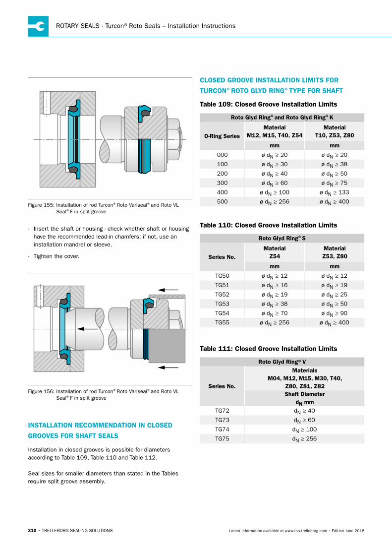
ROTARY SEALS · Turcon®Roto Seals – Installation Instructions
310 • TRELLEBORG SEALING SOLUTIONS Latest information available at www.tss.trelleborg.com • Edition June 2018
Figure 155: Installation of rod Turcon®Roto Variseal®and Roto VL Seal®F in split groove
- Insert the shaft or housing - check whether shaft or housing have the recommended lead-in chamfers; if not, use an installation mandrel or sleeve.
- Tighten the cover.
Figure 156: Installation of rod Turcon®Roto Variseal®and Roto VL Seal®F in split groove
INSTALLATION RECOMMENDATION IN CLOSED
GROOVES FOR SHAFT SEALS
Installation in closed grooves is possible for diameters according to Table 109, Table 110 and Table 112.
Seal sizes for smaller diameters than stated in the Tables require split groove assembly.
CLOSED GROOVE INSTALLATION LIMITS FOR
TURCON®ROTO GLYD RING®TYPE FOR SHAFT
Table 109: Closed Groove Installation Limits
Roto Glyd Ring®and Roto Glyd Ring®K
O-Ring Series Material
M12, M15, T40, Z54Material
T10, Z53, Z80
mm mm
000 ø dN ≥ 20 ø dN ≥ 20
100 ø dN ≥ 30 ø dN ≥ 38
200 ø dN ≥ 40 ø dN ≥ 50
300 ø dN ≥ 60 ø dN ≥ 75
400 ø dN ≥ 100 ø dN ≥ 133
500 ø dN ≥ 256 ø dN ≥ 400
Table 110: Closed Groove Installation Limits
Roto Glyd Ring®S
Series No. Material
Z54Material Z53, Z80
mm mm
TG50 ø dN ≥ 12 ø dN ≥ 12
TG51 ø dN ≥ 16 ø dN ≥ 19
TG52 ø dN ≥ 19 ø dN ≥ 25
TG53 ø dN ≥ 38 ø dN ≥ 50
TG54 ø dN ≥ 70 ø dN ≥ 90
TG55 ø dN ≥ 256 ø dN ≥ 400
Table 111: Closed Groove Installation Limits
Roto Glyd Ring®V
Series No.
MaterialsM04, M12, M15, M30, T40,
Z80, Z81, Z82Shaft Diameter
dN mmTG72 dN ≥ 40
TG73 dN ≥ 60
TG74 dN ≥ 100
TG75 dN ≥ 256
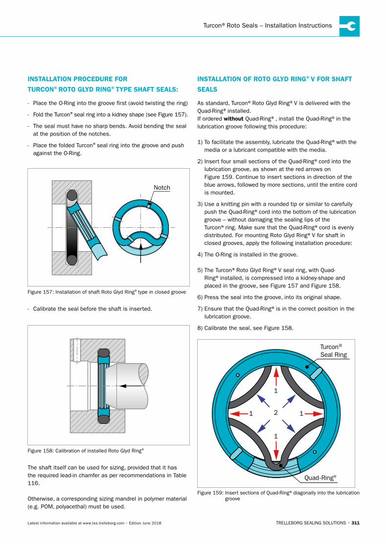
Turcon®Roto Seals – Installation Instructions
TRELLEBORG SEALING SOLUTIONS • 311Latest information available at www.tss.trelleborg.com • Edition June 2018
INSTALLATION PROCEDURE FOR
TURCON®ROTO GLYD RING®TYPE SHAFT SEALS:
- Place the O-Ring into the groove first (avoid twisting the ring)
- Fold the Turcon®seal ring into a kidney shape (see Figure 157).
- The seal must have no sharp bends. Avoid bending the seal at the position of the notches.
- Place the folded Turcon®seal ring into the groove and push against the O-Ring.
Notch
Figure 157: Installation of shaft Roto Glyd Ring®type in closed groove
- Calibrate the seal before the shaft is inserted.
Figure 158: Calibration of installed Roto Glyd Ring®
The shaft itself can be used for sizing, provided that it has the required lead-in chamfer as per recommendations in Table 116.
Otherwise, a corresponding sizing mandrel in polymer material (e.g. POM, polyacethal) must be used.
INSTALLATION OF ROTO GLYD RING®V FOR SHAFT
SEALS
As standard, Turcon®Roto Glyd Ring®V is delivered with the Quad-Ring®installed.If ordered without Quad-Ring®, install the Quad-Ring®in the lubrication groove following this procedure:
1) To facilitate the assembly, lubricate the Quad-Ring®with the media or a lubricant compatible with the media.
2) Insert four small sections of the Quad-Ring®cord into the lubrication groove, as shown at the red arrows on Figure 159. Continue to insert sections in direction of the blue arrows, followed by more sections, until the entire cord is mounted.
3) Use a knitting pin with a rounded tip or similar to carefully push the Quad-Ring®cord into the bottom of the lubrication groove – without damaging the sealing lips of the Turcon®ring. Make sure that the Quad-Ring®cord is evenly distributed. For mounting Roto Glyd Ring®V for shaft in closed grooves, apply the following installation procedure:
4) The O-Ring is installed in the groove.
5) The Turcon®Roto Glyd Ring®V seal ring, with Quad-Ring®installed, is compressed into a kidney-shape and placed in the groove, see Figure 157 and Figure 158.
6) Press the seal into the groove, into its original shape.
7) Ensure that the Quad-Ring®is in the correct position in the lubrication groove.
8) Calibrate the seal, see Figure 158.
Turcon® Seal Ring
Quad-Ring®
1
1
11 2
Figure 159: Insert sections of Quad-Ring®diagonally into the lubrication groove
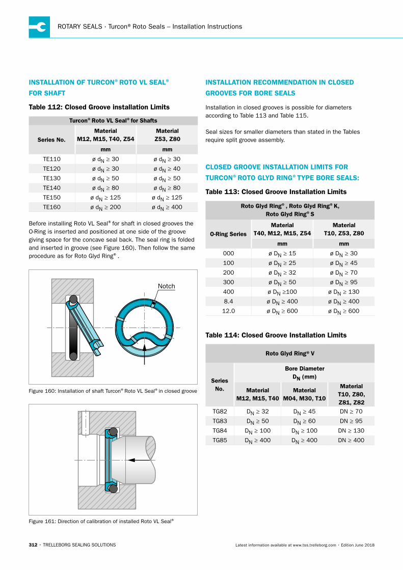
ROTARY SEALS · Turcon®Roto Seals – Installation Instructions
312 • TRELLEBORG SEALING SOLUTIONS Latest information available at www.tss.trelleborg.com • Edition June 2018
INSTALLATION OF TURCON®ROTO VL SEAL®
FOR SHAFT
Table 112: Closed Groove installation Limits
Turcon®Roto VL Seal®for Shafts
Series No. Material
M12, M15, T40, Z54Material Z53, Z80
mm mm
TE110 ø dN ≥ 30 ø dN ≥ 30
TE120 ø dN ≥ 30 ø dN ≥ 40
TE130 ø dN ≥ 50 ø dN ≥ 50
TE140 ø dN ≥ 80 ø dN ≥ 80
TE150 ø dN ≥ 125 ø dN ≥ 125
TE160 ø dN ≥ 200 ø dN ≥ 400
Before installing Roto VL Seal®for shaft in closed grooves the O-Ring is inserted and positioned at one side of the groove giving space for the concave seal back. The seal ring is folded and inserted in groove (see Figure 160). Then follow the same procedure as for Roto Glyd Ring®.
Notch
Figure 160: Installation of shaft Turcon®Roto VL Seal®in closed groove
Figure 161: Direction of calibration of installed Roto VL Seal®
INSTALLATION RECOMMENDATION IN CLOSED
GROOVES FOR BORE SEALS
Installation in closed grooves is possible for diameters according to Table 113 and Table 115.
Seal sizes for smaller diameters than stated in the Tables require split groove assembly.
CLOSED GROOVE INSTALLATION LIMITS FOR
TURCON®ROTO GLYD RING®TYPE BORE SEALS:
Table 113: Closed Groove Installation Limits
Roto Glyd Ring®, Roto Glyd Ring®K, Roto Glyd Ring®S
O-Ring SeriesMaterial
T40, M12, M15, Z54Material
T10, Z53, Z80
mm mm
000 ø DN ≥ 15 ø DN ≥ 30
100 ø DN ≥ 25 ø DN ≥ 45
200 ø DN ≥ 32 ø DN ≥ 70
300 ø DN ≥ 50 ø DN ≥ 95
400 ø DN ≥100 ø DN ≥ 130
8.4 ø DN ≥ 400 ø DN ≥ 400
12.0 ø DN ≥ 600 ø DN ≥ 600
Table 114: Closed Groove Installation Limits
Roto Glyd Ring®V
Series No.
Bore DiameterDN (mm)
MaterialM12, M15, T40
MaterialM04, M30, T10
MaterialT10, Z80, Z81, Z82
TG82 DN ≥ 32 DN ≥ 45 DN ≥ 70
TG83 DN ≥ 50 DN ≥ 60 DN ≥ 95
TG84 DN ≥ 100 DN ≥ 100 DN ≥ 130
TG85 DN ≥ 400 DN ≥ 400 DN ≥ 400
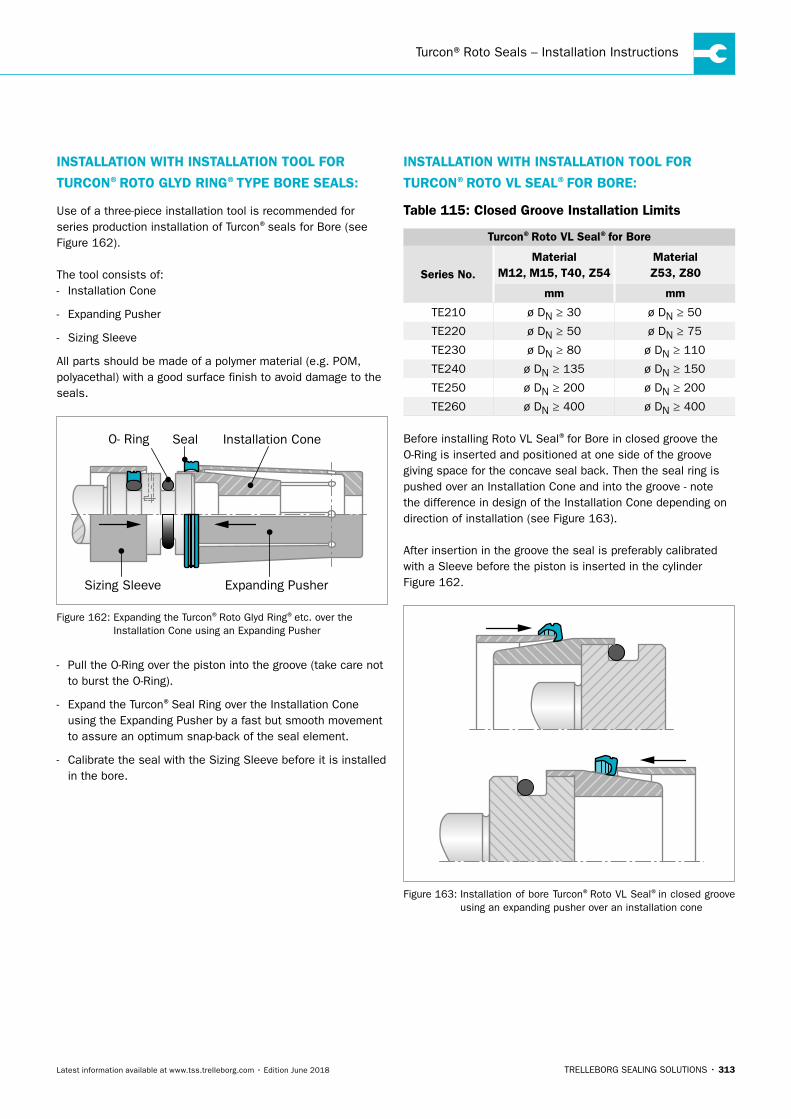
Turcon®Roto Seals – Installation Instructions
TRELLEBORG SEALING SOLUTIONS • 313Latest information available at www.tss.trelleborg.com • Edition June 2018
INSTALLATION WITH INSTALLATION TOOL FOR
TURCON®ROTO GLYD RING®TYPE BORE SEALS:
Use of a three-piece installation tool is recommended for series production installation of Turcon®seals for Bore (see Figure 162).
The tool consists of: - Installation Cone
- Expanding Pusher
- Sizing Sleeve
All parts should be made of a polymer material (e.g. POM, polyacethal) with a good surface finish to avoid damage to the seals.
Figure 131 Installation Cone using an Expanding Pusher
Installation Cone
Expanding PusherSizing Sleeve
SealO- Ring
Figure 162: Expanding the Turcon®Roto Glyd Ring®etc. over the Installation Cone using an Expanding Pusher
- Pull the O-Ring over the piston into the groove (take care not to burst the O-Ring).
- Expand the Turcon®Seal Ring over the Installation Cone using the Expanding Pusher by a fast but smooth movement to assure an optimum snap-back of the seal element.
- Calibrate the seal with the Sizing Sleeve before it is installed in the bore.
INSTALLATION WITH INSTALLATION TOOL FOR
TURCON®ROTO VL SEAL®FOR BORE:
Table 115: Closed Groove Installation Limits
Turcon®Roto VL Seal®for Bore
Series No.Material
M12, M15, T40, Z54Material Z53, Z80
mm mm
TE210 ø DN ≥ 30 ø DN ≥ 50
TE220 ø DN ≥ 50 ø DN ≥ 75
TE230 ø DN ≥ 80 ø DN ≥ 110
TE240 ø DN ≥ 135 ø DN ≥ 150
TE250 ø DN ≥ 200 ø DN ≥ 200
TE260 ø DN ≥ 400 ø DN ≥ 400
Before installing Roto VL Seal®for Bore in closed groove the O-Ring is inserted and positioned at one side of the groove giving space for the concave seal back. Then the seal ring is pushed over an Installation Cone and into the groove - note the difference in design of the Installation Cone depending on direction of installation (see Figure 163).
After insertion in the groove the seal is preferably calibrated with a Sleeve before the piston is inserted in the cylinder Figure 162.
Figure 163: Installation of bore Turcon®Roto VL Seal®in closed groove using an expanding pusher over an installation cone
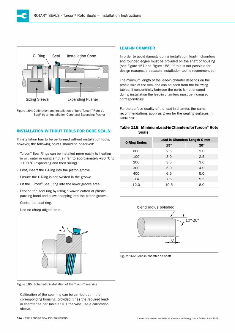
ROTARY SEALS · Turcon®Roto Seals – Installation Instructions
314 • TRELLEBORG SEALING SOLUTIONS Latest information available at www.tss.trelleborg.com • Edition June 2018
Figure 131 by an Installation Cone and Expanding Pusher
Installation Cone
Expanding PusherSizing Sleeve
SealO- Ring
Figure 164: Calibration and installation of bore Turcon®Roto VL Seal®by an Installation Cone and Expanding Pusher
INSTALLATION WITHOUT TOOLS FOR BORE SEALS
If installation has to be performed without installation tools, however, the following points should be observed:
- Turcon®Seal Rings can be installed more easily by heating in oil, water or using a hot air fan to approximately +80 °C to +100 °C (expanding and then sizing).
- First, insert the O-Ring into the piston groove.
- Ensure the O-Ring is not twisted in the groove.
- Fit the Turcon®Seal Ring into the lower groove area.
- Expand the seal ring by using a woven cotton or plastic packing band and allow snapping into the piston groove.
- Centre the seal ring.
- Use no sharp edged tools .
Figure 165: Schematic installation of the Turcon®seal ring
- Calibration of the seal ring can be carried out in the corresponding housing, provided it has the required lead-in chamfer as per Table 116. Otherwise use a calibration sleeve.
LEAD-IN CHAMFER
In order to avoid damage during installation, lead-in chamfers and rounded edges must be provided on the shaft or housing (see Figure 157 and Figure 158). If this is not possible for design reasons, a separate installation tool is recommended.
The minimum length of the lead-in chamfer depends on the profile size of the seal and can be seen from the following tables. If concentricity between the parts is not ensured during installation the lead-in chamfers must be increased correspondingly.
For the surface quality of the lead-in chamfer, the same recommendations apply as given for the sealing surfaces in Table 116.
Table 116: Minimum Lead-in Chamfers for Turcon®Roto Seals
O-Ring SeriesLead-in Chamfers Length C mm
15° 20°
000 2.5 2.0
100 3.0 2.5
200 3.5 3.0
300 5.0 4.0
400 6.5 5.0
8.4 7.5 5.5
12.0 10.5 8.0
C
blend radius polished
10°-20°
Figure 166: Lead-in chamfer on shaft
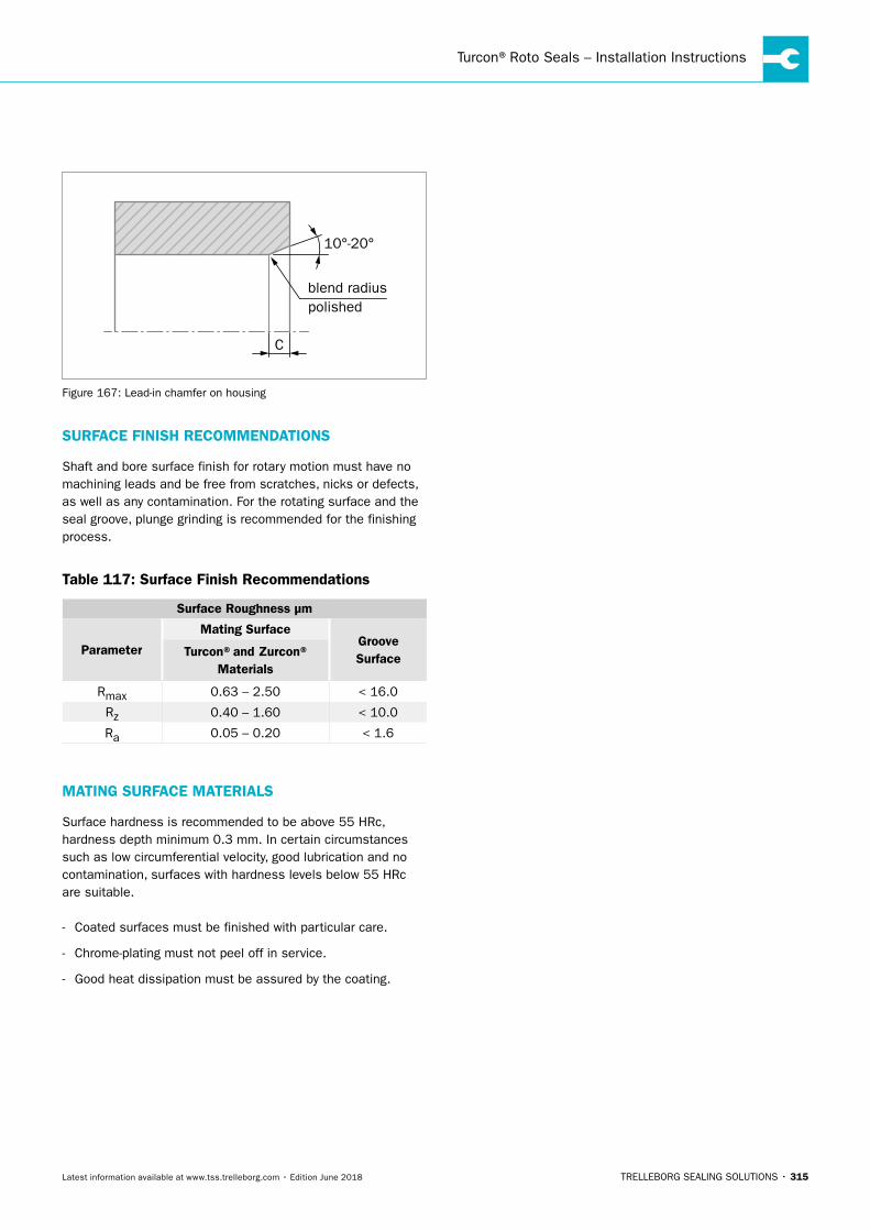
Turcon®Roto Seals – Installation Instructions
TRELLEBORG SEALING SOLUTIONS • 315Latest information available at www.tss.trelleborg.com • Edition June 2018
C
blend radiuspolished
10°-20°
Figure 167: Lead-in chamfer on housing
SURFACE FINISH RECOMMENDATIONS
Shaft and bore surface finish for rotary motion must have no machining leads and be free from scratches, nicks or defects, as well as any contamination. For the rotating surface and the seal groove, plunge grinding is recommended for the finishing process.
Table 117: Surface Finish Recommendations
Surface Roughness μm
Parameter
Mating SurfaceGroove SurfaceTurcon®and Zurcon®
Materials
Rmax 0.63 – 2.50 < 16.0
Rz 0.40 – 1.60 < 10.0
Ra 0.05 – 0.20 < 1.6
MATING SURFACE MATERIALS
Surface hardness is recommended to be above 55 HRc, hardness depth minimum 0.3 mm. In certain circumstances such as low circumferential velocity, good lubrication and no contamination, surfaces with hardness levels below 55 HRc are suitable.
- Coated surfaces must be finished with particular care.
- Chrome-plating must not peel off in service.
- Good heat dissipation must be assured by the coating.
ROTARY SEALS · Turcon®Roto Seals – Installation Instructions
316 • TRELLEBORG SEALING SOLUTIONS Latest information available at www.tss.trelleborg.com • Edition June 2018
TRELLEBORG SEALING SOLUTIONS • 317Latest information available at www.tss.trelleborg.com • Edition June 2018
Turcon®Buffer Ringwith Back-pressure Relief

ROTARY SEALS · Turcon®Buffer Ring with Back-pressure Relief
318 • TRELLEBORG SEALING SOLUTIONS Latest information available at www.tss.trelleborg.com • Edition June 2018
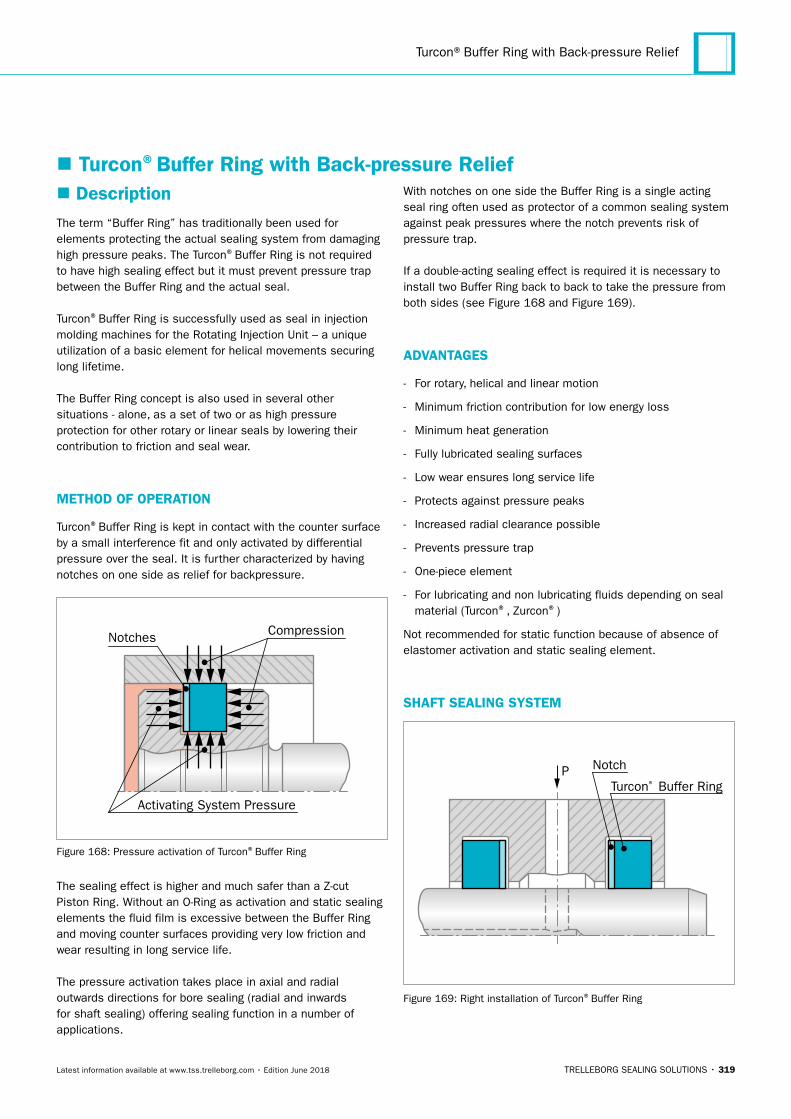
Turcon®Buffer Ring with Back-pressure Relief
TRELLEBORG SEALING SOLUTIONS • 319Latest information available at www.tss.trelleborg.com • Edition June 2018
� Description The term “Buffer Ring” has traditionally been used for elements protecting the actual sealing system from damaging high pressure peaks. The Turcon®Buffer Ring is not required to have high sealing effect but it must prevent pressure trap between the Buffer Ring and the actual seal.
Turcon®Buffer Ring is successfully used as seal in injection molding machines for the Rotating Injection Unit – a unique utilization of a basic element for helical movements securing long lifetime.
The Buffer Ring concept is also used in several other situations - alone, as a set of two or as high pressure protection for other rotary or linear seals by lowering their contribution to friction and seal wear.
METHOD OF OPERATION
Turcon®Buffer Ring is kept in contact with the counter surface by a small interference fit and only activated by differential pressure over the seal. It is further characterized by having notches on one side as relief for backpressure.
CompressionNotches
Activating System Pressure
Figure 168: Pressure activation of Turcon®Buffer Ring
The sealing effect is higher and much safer than a Z-cut Piston Ring. Without an O-Ring as activation and static sealing elements the fluid film is excessive between the Buffer Ring and moving counter surfaces providing very low friction and wear resulting in long service life.
The pressure activation takes place in axial and radial outwards directions for bore sealing (radial and inwards for shaft sealing) offering sealing function in a number of applications.
With notches on one side the Buffer Ring is a single acting seal ring often used as protector of a common sealing system against peak pressures where the notch prevents risk of pressure trap.
If a double-acting sealing effect is required it is necessary to install two Buffer Ring back to back to take the pressure from both sides (see Figure 168 and Figure 169).
ADVANTAGES
- For rotary, helical and linear motion
- Minimum friction contribution for low energy loss
- Minimum heat generation
- Fully lubricated sealing surfaces
- Low wear ensures long service life
- Protects against pressure peaks
- Increased radial clearance possible
- Prevents pressure trap
- One-piece element
- For lubricating and non lubricating fluids depending on seal material (Turcon®, Zurcon®)
Not recommended for static function because of absence of elastomer activation and static sealing element.
SHAFT SEALING SYSTEM
PTurcon® Buffer Ring
Notch
Figure 169: Right installation of Turcon®Buffer Ring
� Turcon®Buffer Ring with Back-pressure Relief
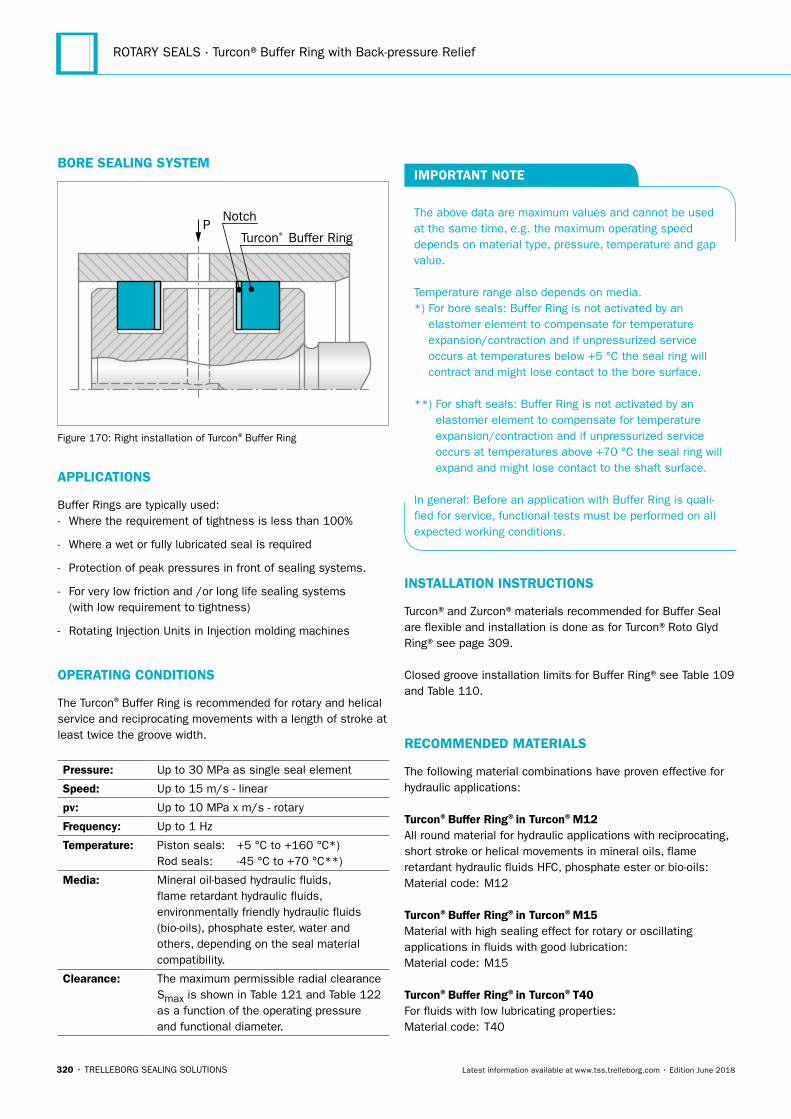
ROTARY SEALS · Turcon®Buffer Ring with Back-pressure Relief
320 • TRELLEBORG SEALING SOLUTIONS Latest information available at www.tss.trelleborg.com • Edition June 2018
BORE SEALING SYSTEM
PTurcon® Buffer Ring
Notch
Figure 170: Right installation of Turcon®Buffer Ring
APPLICATIONS
Buffer Rings are typically used: - Where the requirement of tightness is less than 100%
- Where a wet or fully lubricated seal is required
- Protection of peak pressures in front of sealing systems.
- For very low friction and /or long life sealing systems (with low requirement to tightness)
- Rotating Injection Units in Injection molding machines
OPERATING CONDITIONS
The Turcon®Buffer Ring is recommended for rotary and helical service and reciprocating movements with a length of stroke at least twice the groove width.
Pressure: Up to 30 MPa as single seal element
Speed: Up to 15 m/s - linear
pv: Up to 10 MPa x m/s - rotary
Frequency: Up to 1 Hz
Temperature: Piston seals: +5 °C to +160 °C*)Rod seals: -45 °C to +70 °C**)
Media: Mineral oil-based hydraulic fluids, flame retardant hydraulic fluids, environmentally friendly hydraulic fluids (bio-oils), phosphate ester, water and others, depending on the seal material compatibility.
Clearance: The maximum permissible radial clearance Smax is shown in Table 121 and Table 122 as a function of the operating pressure and functional diameter.
IMPORTANT NOTE
The above data are maximum values and cannot be used at the same time, e.g. the maximum operating speed depends on material type, pressure, temperature and gap value.
Temperature range also depends on media.*) For bore seals: Buffer Ring is not activated by an
elastomer element to compensate for temperature expansion/contraction and if unpressurized service occurs at temperatures below +5 °C the seal ring will contract and might lose contact to the bore surface.
**) For shaft seals: Buffer Ring is not activated by an elastomer element to compensate for temperature expansion/contraction and if unpressurized service occurs at temperatures above +70 °C the seal ring will expand and might lose contact to the shaft surface.
In general: Before an application with Buffer Ring is quali-fied for service, functional tests must be performed on all expected working conditions.
INSTALLATION INSTRUCTIONS
Turcon®and Zurcon®materials recommended for Buffer Seal are flexible and installation is done as for Turcon®Roto Glyd Ring®see page 309.
Closed groove installation limits for Buffer Ring®see Table 109 and Table 110.
RECOMMENDED MATERIALS
The following material combinations have proven effective for hydraulic applications:
Turcon®Buffer Ring®in Turcon®M12All round material for hydraulic applications with reciprocating, short stroke or helical movements in mineral oils, flame retardant hydraulic fluids HFC, phosphate ester or bio-oils:Material code: M12
Turcon®Buffer Ring®in Turcon®M15Material with high sealing effect for rotary or oscillating applications in fluids with good lubrication:Material code: M15
Turcon®Buffer Ring®in Turcon®T40For fluids with low lubricating properties:Material code: T40
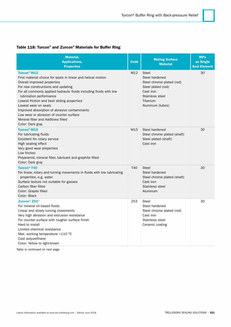
Turcon®Buffer Ring with Back-pressure Relief
TRELLEBORG SEALING SOLUTIONS • 321Latest information available at www.tss.trelleborg.com • Edition June 2018
Table 118: Turcon®and Zurcon®Materials for Buffer Ring
Material, Applications, Properties
CodeMating Surface
Material
MPa as Single
Seal Element
Turcon®M12First material choice for seals in linear and helical motionOverall improved propertiesFor new constructions and updatingFor all commonly applied hydraulic fluids including fluids with low lubrication performanceLowest friction and best sliding propertiesLowest wear on sealsImproved absorption of abrasive contaminantsLow wear or abrasion of counter surfaceMineral fiber and Additives filledColor: Dark gray
M12 SteelSteel hardenedSteel chrome plated (rod)Steel plated (rod)Cast ironStainless steelTitaniumAluminum (tubes)
30
Turcon®M15For lubricating fluids Excellent for rotary serviceHigh sealing effectVery good wear propertiesLow frictionPolyaramid, mineral fiber, lubricant and graphite filledColor: Dark gray
M15 Steel hardenedSteel chrome plated (shaft)Steel plated (shaft)Cast iron
30
Turcon®T40For linear, rotary and turning movements in fluids with low lubricating properties, e.g. waterSurface texture not suitable for gassesCarbon fiber filledColor: Grayite filledColor: Black
T40 SteelSteel hardenedSteel chrome plated (shaft)Cast ironStainless steelAluminum
30
Zurcon®Z53*
For mineral oil based fluidsLinear and slowly turning movementsVery high abrasion and extrusion resistanceFor counter surface with rougher surface finishHard to installLimited chemical resistanceMax. working temperature +110 °CCast polyurethaneColor: Yellow to light-brown
Z53 SteelSteel hardenedSteel chrome plated (rod)Cast ironStainless steelCeramic coating
30
Table is continued on next page
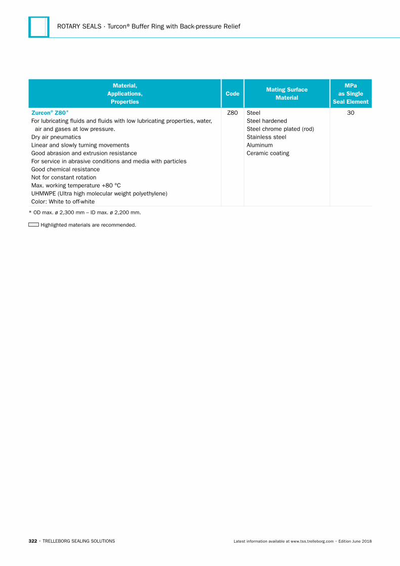
ROTARY SEALS · Turcon®Buffer Ring with Back-pressure Relief
322 • TRELLEBORG SEALING SOLUTIONS Latest information available at www.tss.trelleborg.com • Edition June 2018
Material, Applications, Properties
CodeMating Surface
Material
MPa as Single
Seal Element
Zurcon®Z80*
For lubricating fluids and fluids with low lubricating properties, water, air and gases at low pressure.Dry air pneumaticsLinear and slowly turning movementsGood abrasion and extrusion resistanceFor service in abrasive conditions and media with particlesGood chemical resistanceNot for constant rotationMax. working temperature +80 °CUHMWPE (Ultra high molecular weight polyethylene)Color: White to off-white
Z80 SteelSteel hardenedSteel chrome plated (rod)Stainless steelAluminumCeramic coating
30
* OD max. ø 2,300 mm – ID max. ø 2,200 mm.
Highlighted materials are recommended.
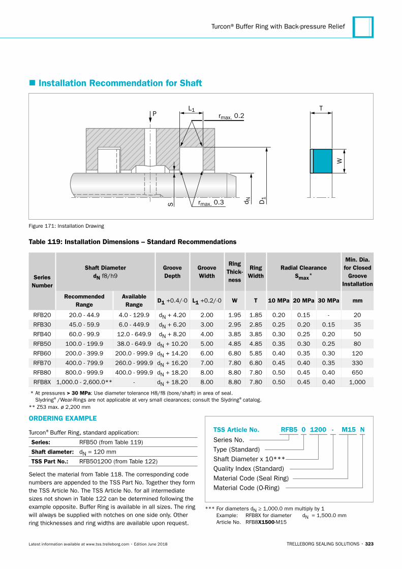
Turcon®Buffer Ring with Back-pressure Relief
TRELLEBORG SEALING SOLUTIONS • 323Latest information available at www.tss.trelleborg.com • Edition June 2018
� Installation Recommendation for Shaft
PL1
S rmax. 0.3
T
W
d N D1
rmax. 0.2
Figure 171: Installation Drawing
Table 119: Installation Dimensions – Standard Recommendations
Series Number
Shaft DiameterdN f8/h9
Groove Depth
Groove Width
Ring Thick- ness
Ring Width
Radial ClearanceSmax*
Min. Dia. for Closed
Groove Installation
Recommended Range
Available Range
D1 +0.4/-0 L1 +0.2/-0 W T 10 MPa 20 MPa 30 MPa mm
RFB20 20.0 - 44.9 4.0 - 129.9 dN + 4.20 2.00 1.95 1.85 0.20 0.15 - 20
RFB30 45.0 - 59.9 6.0 - 449.9 dN + 6.20 3.00 2.95 2.85 0.25 0.20 0.15 35
RFB40 60.0 - 99.9 12.0 - 649.9 dN + 8.20 4.00 3.85 3.85 0.30 0.25 0.20 50
RFB50 100.0 - 199.9 38.0 - 649.9 dN + 10.20 5.00 4.85 4.85 0.35 0.30 0.25 80
RFB60 200.0 - 399.9 200.0 - 999.9 dN + 14.20 6.00 6.80 5.85 0.40 0.35 0.30 120
RFB70 400.0 - 799.9 260.0 - 999.9 dN + 16.20 7.00 7.80 6.80 0.45 0.40 0.35 330
RFB80 800.0 - 999.9 400.0 - 999.9 dN + 18.20 8.00 8.80 7.80 0.50 0.45 0.40 650
RFB8X 1,000.0 - 2,600.0** - dN + 18.20 8.00 8.80 7.80 0.50 0.45 0.40 1,000
* At pressures > 30 MPa: Use diameter tolerance H8/f8 (bore/shaft) in area of seal. Slydring®/Wear-Rings are not applicable at very small clearances; consult the Slydring®catalog.
** Z53 max. ø 2,200 mm
ORDERING EXAMPLE
Turcon®Buffer Ring, standard application:
Series: RFB50 (from Table 119)
Shaft diameter: dN = 120 mm
TSS Part No.: RFB501200 (from Table 122)
Select the material from Table 118. The corresponding code numbers are appended to the TSS Part No. Together they form the TSS Article No. The TSS Article No. for all intermediate sizes not shown in Table 122 can be determined following the example opposite. Buffer Ring is available in all sizes. The ring will always be supplied with notches on one side only. Other ring thicknesses and ring widths are available upon request.
TSS Article No.
Series No.Type (Standard)Shaft Diameter x 10***Quality Index (Standard)Material Code (Seal Ring)Material Code (O-Ring)
-RFB5 0 1200 M15 N
*** For diameters dN ≥ 1,000.0 mm multiply by 1 Example: RFB8X for diameter dN = 1,500.0 mm Article No. RFB8X1500-M15
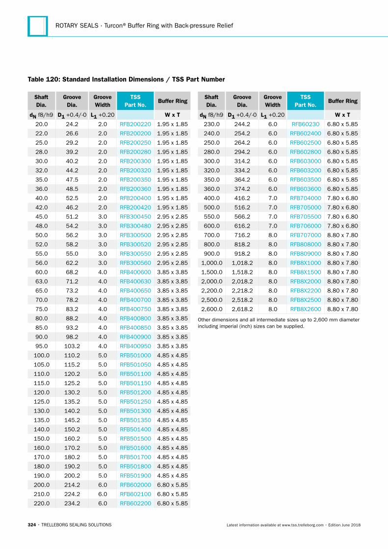
ROTARY SEALS · Turcon®Buffer Ring with Back-pressure Relief
324 • TRELLEBORG SEALING SOLUTIONS Latest information available at www.tss.trelleborg.com • Edition June 2018
Shaft Dia.
Groove Dia.
Groove Width
TSS Part No.
Buffer Ring
dN f8/h9 D1 +0.4/-0 L1 +0.20 W x T
20.0 24.2 2.0 RFB200220 1.95 x 1.85
22.0 26.6 2.0 RFB200200 1.95 x 1.85
25.0 29.2 2.0 RFB200250 1.95 x 1.85
28.0 39.2 2.0 RFB200280 1.95 x 1.85
30.0 40.2 2.0 RFB200300 1.95 x 1.85
32.0 44.2 2.0 RFB200320 1.95 x 1.85
35.0 47.5 2.0 RFB200350 1.95 x 1.85
36.0 48.5 2.0 RFB200360 1.95 x 1.85
40.0 52.5 2.0 RFB200400 1.95 x 1.85
42.0 46.2 2.0 RFB200420 1.95 x 1.85
45.0 51.2 3.0 RFB300450 2.95 x 2.85
48.0 54.2 3.0 RFB300480 2.95 x 2.85
50.0 56.2 3.0 RFB300500 2.95 x 2.85
52.0 58.2 3.0 RFB300520 2.95 x 2.85
55.0 55.0 3.0 RFB300550 2.95 x 2.85
56.0 62.2 3.0 RFB300560 2.95 x 2.85
60.0 68.2 4.0 RFB400600 3.85 x 3.85
63.0 71.2 4.0 RFB400630 3.85 x 3.85
65.0 73.2 4.0 RFB400650 3.85 x 3.85
70.0 78.2 4.0 RFB400700 3.85 x 3.85
75.0 83.2 4.0 RFB400750 3.85 x 3.85
80.0 88.2 4.0 RFB400800 3.85 x 3.85
85.0 93.2 4.0 RFB400850 3.85 x 3.85
90.0 98.2 4.0 RFB400900 3.85 x 3.85
95.0 103.2 4.0 RFB400950 3.85 x 3.85
100.0 110.2 5.0 RFB501000 4.85 x 4.85
105.0 115.2 5.0 RFB501050 4.85 x 4.85
110.0 120.2 5.0 RFB501100 4.85 x 4.85
115.0 125.2 5.0 RFB501150 4.85 x 4.85
120.0 130.2 5.0 RFB501200 4.85 x 4.85
125.0 135.2 5.0 RFB501250 4.85 x 4.85
130.0 140.2 5.0 RFB501300 4.85 x 4.85
135.0 145.2 5.0 RFB501350 4.85 x 4.85
140.0 150.2 5.0 RFB501400 4.85 x 4.85
150.0 160.2 5.0 RFB501500 4.85 x 4.85
160.0 170.2 5.0 RFB501600 4.85 x 4.85
170.0 180.2 5.0 RFB501700 4.85 x 4.85
180.0 190.2 5.0 RFB501800 4.85 x 4.85
190.0 200.2 5.0 RFB501900 4.85 x 4.85
200.0 214.2 6.0 RFB602000 6.80 x 5.85
210.0 224.2 6.0 RFB602100 6.80 x 5.85
220.0 234.2 6.0 RFB602200 6.80 x 5.85
Shaft Dia.
Groove Dia.
Groove Width
TSS Part No.
Buffer Ring
dN f8/h9 D1 +0.4/-0 L1 +0.20 W x T
230.0 244.2 6.0 RFB60230 6.80 x 5.85
240.0 254.2 6.0 RFB602400 6.80 x 5.85
250.0 264.2 6.0 RFB602500 6.80 x 5.85
280.0 294.2 6.0 RFB602800 6.80 x 5.85
300.0 314.2 6.0 RFB603000 6.80 x 5.85
320.0 334.2 6.0 RFB603200 6.80 x 5.85
350.0 364.2 6.0 RFB603500 6.80 x 5.85
360.0 374.2 6.0 RFB603600 6.80 x 5.85
400.0 416.2 7.0 RFB704000 7.80 x 6.80
500.0 516.2 7.0 RFB705000 7.80 x 6.80
550.0 566.2 7.0 RFB705500 7.80 x 6.80
600.0 616.2 7.0 RFB706000 7.80 x 6.80
700.0 716.2 8.0 RFB707000 8.80 x 7.80
800.0 818.2 8.0 RFB808000 8.80 x 7.80
900.0 918.2 8.0 RFB809000 8.80 x 7.80
1,000.0 1,018.2 8.0 RFB8X1000 8.80 x 7.80
1,500.0 1,518.2 8.0 RFB8X1500 8.80 x 7.80
2,000.0 2,018.2 8.0 RFB8X2000 8.80 x 7.80
2,200.0 2,218.2 8.0 RFB8X2200 8.80 x 7.80
2,500.0 2,518.2 8.0 RFB8X2500 8.80 x 7.80
2,600.0 2,618.2 8.0 RFB8X2600 8.80 x 7.80
Other dimensions and all intermediate sizes up to 2,600 mm diameter including imperial (inch) sizes can be supplied.
Table 120: Standard Installation Dimensions / TSS Part Number
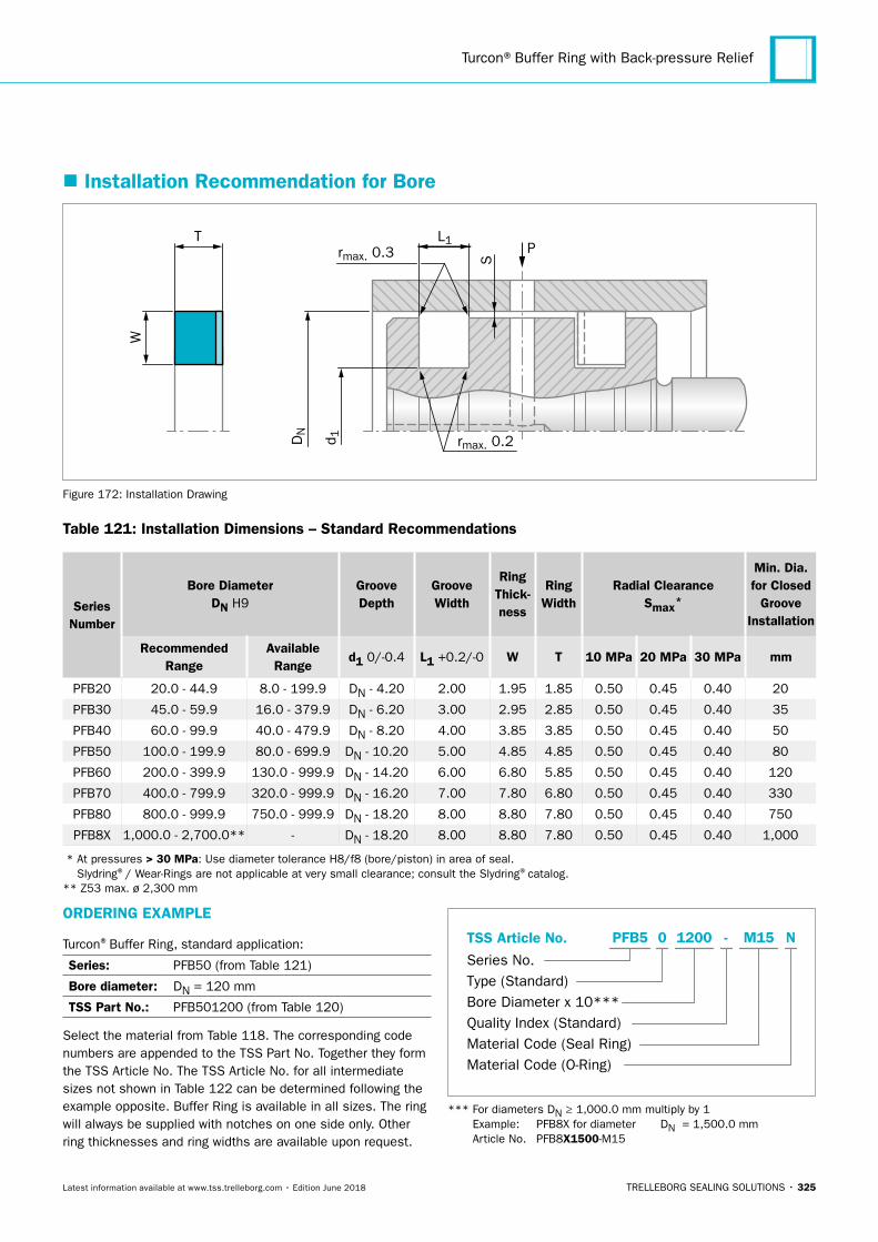
Turcon®Buffer Ring with Back-pressure Relief
TRELLEBORG SEALING SOLUTIONS • 325Latest information available at www.tss.trelleborg.com • Edition June 2018
� Installation Recommendation for Bore
PT
W
S
L1rmax. 0.3
DN
d 1 rmax. 0.2
Figure 172: Installation Drawing
Table 121: Installation Dimensions – Standard Recommendations
Series Number
Bore DiameterDN H9
Groove Depth
Groove Width
Ring Thick- ness
Ring Width
Radial ClearanceSmax*
Min. Dia. for Closed
Groove Installation
Recommended Range
Available Range
d1 0/-0.4 L1 +0.2/-0 W T 10 MPa 20 MPa 30 MPa mm
PFB20 20.0 - 44.9 8.0 - 199.9 DN - 4.20 2.00 1.95 1.85 0.50 0.45 0.40 20
PFB30 45.0 - 59.9 16.0 - 379.9 DN - 6.20 3.00 2.95 2.85 0.50 0.45 0.40 35
PFB40 60.0 - 99.9 40.0 - 479.9 DN - 8.20 4.00 3.85 3.85 0.50 0.45 0.40 50
PFB50 100.0 - 199.9 80.0 - 699.9 DN - 10.20 5.00 4.85 4.85 0.50 0.45 0.40 80
PFB60 200.0 - 399.9 130.0 - 999.9 DN - 14.20 6.00 6.80 5.85 0.50 0.45 0.40 120
PFB70 400.0 - 799.9 320.0 - 999.9 DN - 16.20 7.00 7.80 6.80 0.50 0.45 0.40 330
PFB80 800.0 - 999.9 750.0 - 999.9 DN - 18.20 8.00 8.80 7.80 0.50 0.45 0.40 750
PFB8X 1,000.0 - 2,700.0** - DN - 18.20 8.00 8.80 7.80 0.50 0.45 0.40 1,000
* At pressures > 30 MPa: Use diameter tolerance H8/f8 (bore/piston) in area of seal. Slydring®/ Wear-Rings are not applicable at very small clearance; consult the Slydring®catalog.
** Z53 max. ø 2,300 mm
ORDERING EXAMPLE
Turcon®Buffer Ring, standard application:
Series: PFB50 (from Table 121)
Bore diameter: DN = 120 mm
TSS Part No.: PFB501200 (from Table 120)
Select the material from Table 118. The corresponding code numbers are appended to the TSS Part No. Together they form the TSS Article No. The TSS Article No. for all intermediate sizes not shown in Table 122 can be determined following the example opposite. Buffer Ring is available in all sizes. The ring will always be supplied with notches on one side only. Other ring thicknesses and ring widths are available upon request.
TSS Article No.
Series No.Type (Standard)Bore Diameter x 10***Quality Index (Standard)Material Code (Seal Ring)Material Code (O-Ring)
-PFB5 0 1200 M15 N
*** For diameters DN ≥ 1,000.0 mm multiply by 1 Example: PFB8X for diameter DN = 1,500.0 mm Article No. PFB8X1500-M15
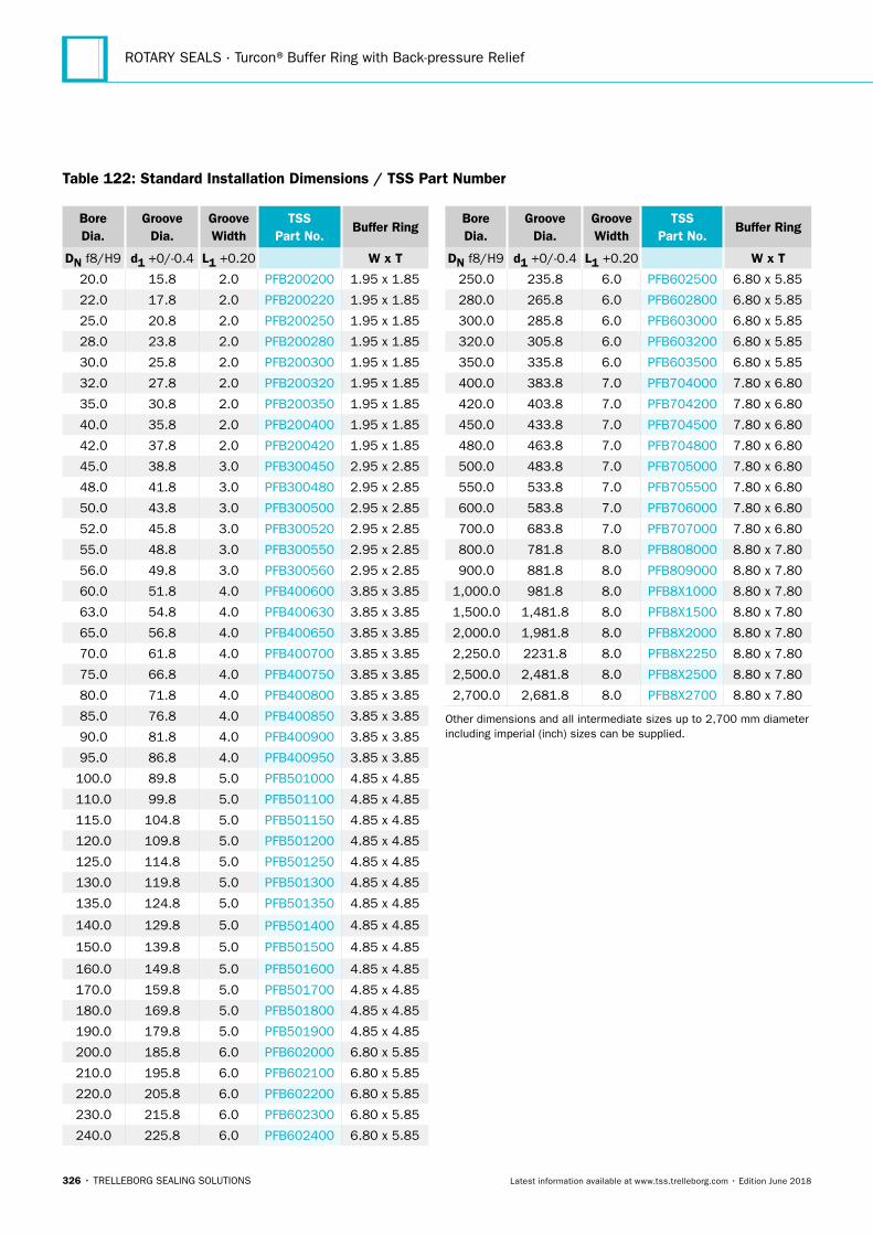
ROTARY SEALS · Turcon®Buffer Ring with Back-pressure Relief
326 • TRELLEBORG SEALING SOLUTIONS Latest information available at www.tss.trelleborg.com • Edition June 2018
Bore Dia.
Groove Dia.
Groove Width
TSS Part No.
Buffer Ring
DN f8/H9 d1 +0/-0.4 L1 +0.20 W x T
20.0 15.8 2.0 PFB200200 1.95 x 1.85
22.0 17.8 2.0 PFB200220 1.95 x 1.85
25.0 20.8 2.0 PFB200250 1.95 x 1.85
28.0 23.8 2.0 PFB200280 1.95 x 1.85
30.0 25.8 2.0 PFB200300 1.95 x 1.85
32.0 27.8 2.0 PFB200320 1.95 x 1.85
35.0 30.8 2.0 PFB200350 1.95 x 1.85
40.0 35.8 2.0 PFB200400 1.95 x 1.85
42.0 37.8 2.0 PFB200420 1.95 x 1.85
45.0 38.8 3.0 PFB300450 2.95 x 2.85
48.0 41.8 3.0 PFB300480 2.95 x 2.85
50.0 43.8 3.0 PFB300500 2.95 x 2.85
52.0 45.8 3.0 PFB300520 2.95 x 2.85
55.0 48.8 3.0 PFB300550 2.95 x 2.85
56.0 49.8 3.0 PFB300560 2.95 x 2.85
60.0 51.8 4.0 PFB400600 3.85 x 3.85
63.0 54.8 4.0 PFB400630 3.85 x 3.85
65.0 56.8 4.0 PFB400650 3.85 x 3.85
70.0 61.8 4.0 PFB400700 3.85 x 3.85
75.0 66.8 4.0 PFB400750 3.85 x 3.85
80.0 71.8 4.0 PFB400800 3.85 x 3.85
85.0 76.8 4.0 PFB400850 3.85 x 3.85
90.0 81.8 4.0 PFB400900 3.85 x 3.85
95.0 86.8 4.0 PFB400950 3.85 x 3.85
100.0 89.8 5.0 PFB501000 4.85 x 4.85
110.0 99.8 5.0 PFB501100 4.85 x 4.85
115.0 104.8 5.0 PFB501150 4.85 x 4.85
120.0 109.8 5.0 PFB501200 4.85 x 4.85
125.0 114.8 5.0 PFB501250 4.85 x 4.85
130.0 119.8 5.0 PFB501300 4.85 x 4.85
135.0 124.8 5.0 PFB501350 4.85 x 4.85
140.0 129.8 5.0 PFB501400 4.85 x 4.85
150.0 139.8 5.0 PFB501500 4.85 x 4.85
160.0 149.8 5.0 PFB501600 4.85 x 4.85
170.0 159.8 5.0 PFB501700 4.85 x 4.85
180.0 169.8 5.0 PFB501800 4.85 x 4.85
190.0 179.8 5.0 PFB501900 4.85 x 4.85
200.0 185.8 6.0 PFB602000 6.80 x 5.85
210.0 195.8 6.0 PFB602100 6.80 x 5.85
220.0 205.8 6.0 PFB602200 6.80 x 5.85
230.0 215.8 6.0 PFB602300 6.80 x 5.85
240.0 225.8 6.0 PFB602400 6.80 x 5.85
Bore Dia.
Groove Dia.
Groove Width
TSS Part No.
Buffer Ring
DN f8/H9 d1 +0/-0.4 L1 +0.20 W x T
250.0 235.8 6.0 PFB602500 6.80 x 5.85
280.0 265.8 6.0 PFB602800 6.80 x 5.85
300.0 285.8 6.0 PFB603000 6.80 x 5.85
320.0 305.8 6.0 PFB603200 6.80 x 5.85
350.0 335.8 6.0 PFB603500 6.80 x 5.85
400.0 383.8 7.0 PFB704000 7.80 x 6.80
420.0 403.8 7.0 PFB704200 7.80 x 6.80
450.0 433.8 7.0 PFB704500 7.80 x 6.80
480.0 463.8 7.0 PFB704800 7.80 x 6.80
500.0 483.8 7.0 PFB705000 7.80 x 6.80
550.0 533.8 7.0 PFB705500 7.80 x 6.80
600.0 583.8 7.0 PFB706000 7.80 x 6.80
700.0 683.8 7.0 PFB707000 7.80 x 6.80
800.0 781.8 8.0 PFB808000 8.80 x 7.80
900.0 881.8 8.0 PFB809000 8.80 x 7.80
1,000.0 981.8 8.0 PFB8X1000 8.80 x 7.80
1,500.0 1,481.8 8.0 PFB8X1500 8.80 x 7.80
2,000.0 1,981.8 8.0 PFB8X2000 8.80 x 7.80
2,250.0 2231.8 8.0 PFB8X2250 8.80 x 7.80
2,500.0 2,481.8 8.0 PFB8X2500 8.80 x 7.80
2,700.0 2,681.8 8.0 PFB8X2700 8.80 x 7.80
Other dimensions and all intermediate sizes up to 2,700 mm diameter including imperial (inch) sizes can be supplied.
Table 122: Standard Installation Dimensions / TSS Part Number
TRELLEBORG SEALING SOLUTIONS • 327Latest information available at www.tss.trelleborg.com • Edition June 2018
Mechanical Face Seals
ROTARY SEALS · Mechanical Face Seals
328 • TRELLEBORG SEALING SOLUTIONS Latest information available at www.tss.trelleborg.com • Edition June 2018
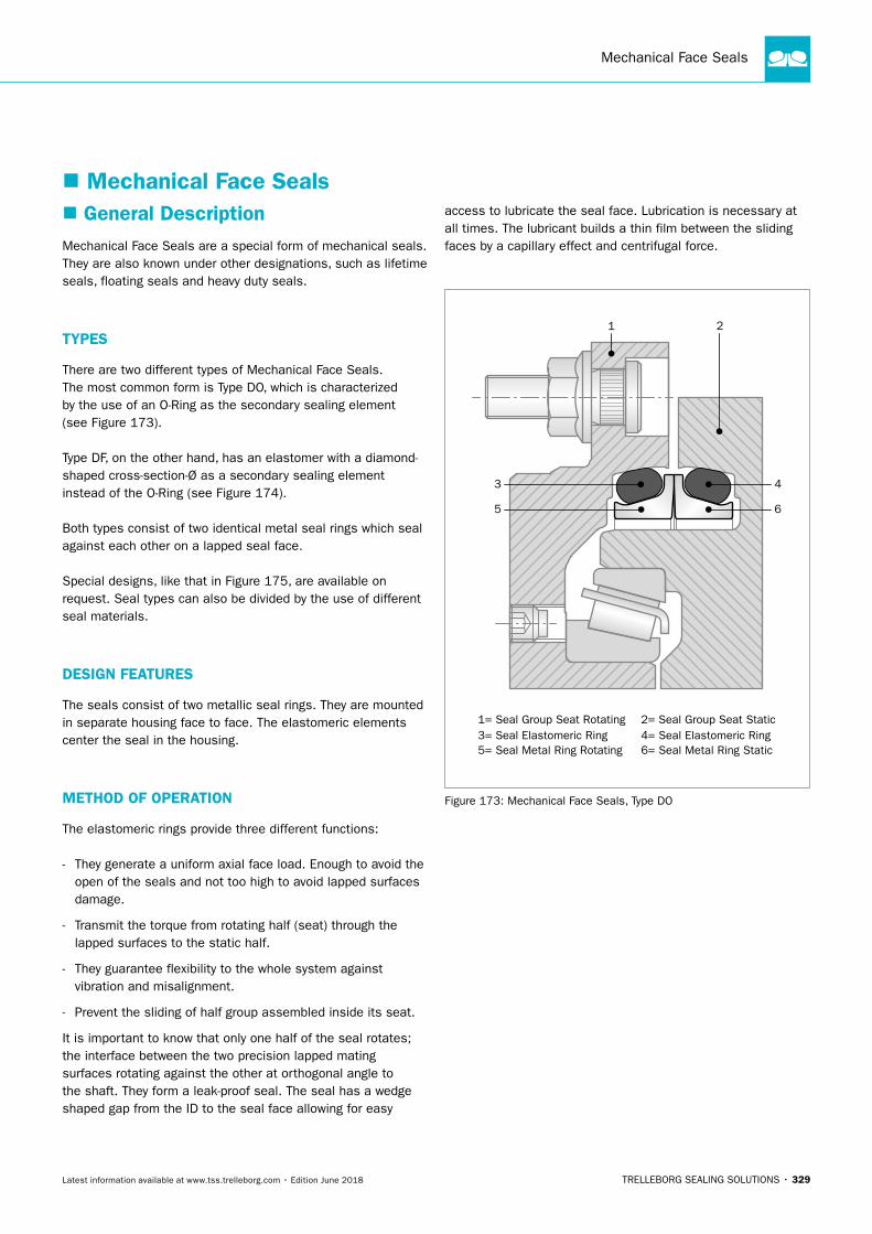
Mechanical Face Seals
TRELLEBORG SEALING SOLUTIONS • 329Latest information available at www.tss.trelleborg.com • Edition June 2018
� General DescriptionMechanical Face Seals are a special form of mechanical seals. They are also known under other designations, such as lifetime seals, floating seals and heavy duty seals.
TYPES
There are two different types of Mechanical Face Seals. The most common form is Type DO, which is characterized by the use of an O-Ring as the secondary sealing element (see Figure 173).
Type DF, on the other hand, has an elastomer with a diamond-shaped cross-section-Ø as a secondary sealing element instead of the O-Ring (see Figure 174).
Both types consist of two identical metal seal rings which seal against each other on a lapped seal face.
Special designs, like that in Figure 175, are available on request. Seal types can also be divided by the use of different seal materials.
DESIGN FEATURES
The seals consist of two metallic seal rings. They are mounted in separate housing face to face. The elastomeric elements center the seal in the housing.
METHOD OF OPERATION
The elastomeric rings provide three different functions:
- They generate a uniform axial face load. Enough to avoid the open of the seals and not too high to avoid lapped surfaces damage.
- Transmit the torque from rotating half (seat) through the lapped surfaces to the static half.
- They guarantee flexibility to the whole system against vibration and misalignment.
- Prevent the sliding of half group assembled inside its seat.
It is important to know that only one half of the seal rotates; the interface between the two precision lapped mating surfaces rotating against the other at orthogonal angle to the shaft. They form a leak-proof seal. The seal has a wedge shaped gap from the ID to the seal face allowing for easy
access to lubricate the seal face. Lubrication is necessary at all times. The lubricant builds a thin film between the sliding faces by a capillary effect and centrifugal force.
1= Seal Group Seat Rotating
5= Seal Metal Ring Rotating
2= Seal Group Seat Static4= Seal Elastomeric Ring3= Seal Elastomeric Ring6= Seal Metal Ring Static
5 6
21
3 4
Figure 173: Mechanical Face Seals, Type DO
� Mechanical Face Seals
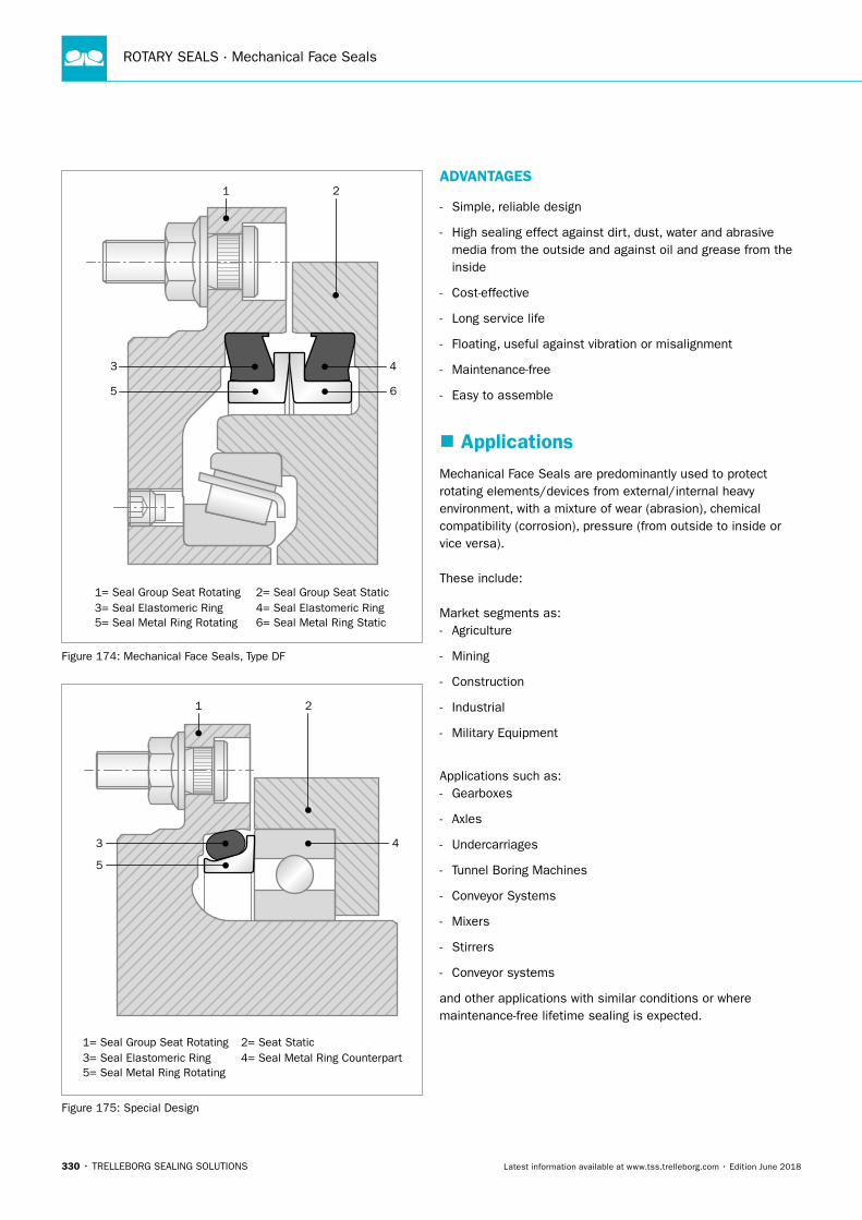
ROTARY SEALS · Mechanical Face Seals
330 • TRELLEBORG SEALING SOLUTIONS Latest information available at www.tss.trelleborg.com • Edition June 2018
1= Seal Group Seat Rotating
5= Seal Metal Ring Rotating
2= Seal Group Seat Static4= Seal Elastomeric Ring3= Seal Elastomeric Ring6= Seal Metal Ring Static
21
5
3
6
4
Figure 174: Mechanical Face Seals, Type DF
1= Seal Group Seat Rotating
5= Seal Metal Ring Rotating
2= Seat Static4= Seal Metal Ring Counterpart3= Seal Elastomeric Ring
21
5
3 4
Figure 175: Special Design
ADVANTAGES
- Simple, reliable design
- High sealing effect against dirt, dust, water and abrasive media from the outside and against oil and grease from the inside
- Cost-effective
- Long service life
- Floating, useful against vibration or misalignment
- Maintenance-free
- Easy to assemble
� ApplicationsMechanical Face Seals are predominantly used to protect rotating elements/devices from external/internal heavy environment, with a mixture of wear (abrasion), chemical compatibility (corrosion), pressure (from outside to inside or vice versa).
These include:
Market segments as: - Agriculture
- Mining
- Construction
- Industrial
- Military Equipment
Applications such as: - Gearboxes
- Axles
- Undercarriages
- Tunnel Boring Machines
- Conveyor Systems
- Mixers
- Stirrers
- Conveyor systems
and other applications with similar conditions or where maintenance-free lifetime sealing is expected.
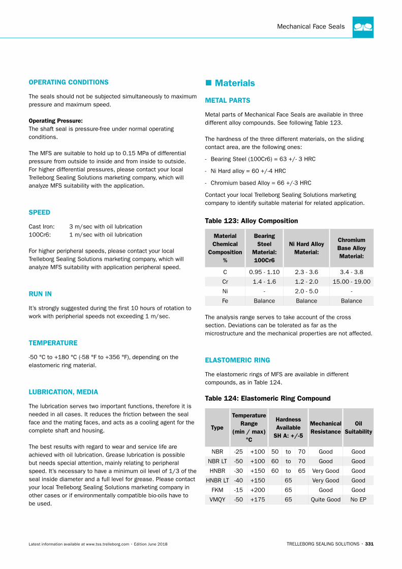
Mechanical Face Seals
TRELLEBORG SEALING SOLUTIONS • 331Latest information available at www.tss.trelleborg.com • Edition June 2018
OPERATING CONDITIONS
The seals should not be subjected simultaneously to maximum pressure and maximum speed.
Operating Pressure: The shaft seal is pressure-free under normal operating conditions.
The MFS are suitable to hold up to 0.15 MPa of differential pressure from outside to inside and from inside to outside. For higher differential pressures, please contact your local Trelleborg Sealing Solutions marketing company, which will analyze MFS suitability with the application.
SPEED
Cast Iron: 3 m/sec with oil lubrication100Cr6: 1 m/sec with oil lubrication
For higher peripheral speeds, please contact your local Trelleborg Sealing Solutions marketing company, which will analyze MFS suitability with application peripheral speed.
RUN IN
It’s strongly suggested during the first 10 hours of rotation to work with peripherial speeds not exceeding 1 m/sec.
TEMPERATURE
-50 °C to +180 °C (-58 °F to +356 °F), depending on the elastomeric ring material.
LUBRICATION, MEDIA
The lubrication serves two important functions, therefore it is needed in all cases. It reduces the friction between the seal face and the mating faces, and acts as a cooling agent for the complete shaft and housing.
The best results with regard to wear and service life are achieved with oil lubrication. Grease lubrication is possible but needs special attention, mainly relating to peripheral speed. It’s necessary to have a minimum oil level of 1/3 of the seal inside diameter and a full level for grease. Please contact your local Trelleborg Sealing Solutions marketing company in other cases or if environmentally compatible bio-oils have to be used.
� Materials
METAL PARTS
Metal parts of Mechanical Face Seals are available in three different alloy compounds. See following Table 123.
The hardness of the three different materials, on the sliding contact area, are the following ones:
- Bearing Steel (100Cr6) = 63 +/- 3 HRC
- Ni Hard alloy = 60 +/-4 HRC
- Chromium based Alloy = 66 +/-3 HRC
Contact your local Trelleborg Sealing Solutions marketing company to identify suitable material for related application.
Table 123: Alloy Composition
Material Chemical
Composition %
Bearing Steel
Material: 100Cr6
Ni Hard Alloy Material:
Chromium Base Alloy Material:
C 0.95 - 1.10 2.3 - 3.6 3.4 - 3.8
Cr 1.4 - 1.6 1.2 - 2.0 15.00 - 19.00
Ni - 2.0 - 5.0 -
Fe Balance Balance Balance
The analysis range serves to take account of the cross section. Deviations can be tolerated as far as the microstructure and the mechanical properties are not affected.
ELASTOMERIC RING
The elastomeric rings of MFS are available in different compounds, as in Table 124.
Table 124: Elastomeric Ring Compound
Type
Temperature Range
(min / max) °C
Hardness Available SHA:+/-5
Mechanical Resistance
Oil Suitability
NBR -25 +100 50 to 70 Good Good
NBR LT -50 +100 60 to 70 Good Good
HNBR -30 +150 60 to 65 Very Good Good
HNBR LT -40 +150 65 Very Good Good
FKM -15 +200 65 Good Good
VMQY -50 +175 65 Quite Good No EP
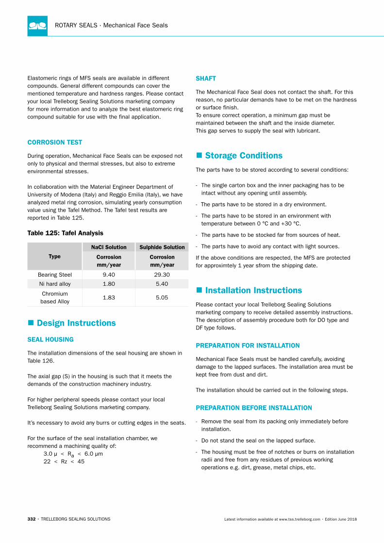
ROTARY SEALS · Mechanical Face Seals
332 • TRELLEBORG SEALING SOLUTIONS Latest information available at www.tss.trelleborg.com • Edition June 2018
Elastomeric rings of MFS seals are available in different compounds. General different compounds can cover the mentioned temperature and hardness ranges. Please contact your local Trelleborg Sealing Solutions marketing company for more information and to analyze the best elastomeric ring compound suitable for use with the final application.
CORROSION TEST
During operation, Mechanical Face Seals can be exposed not only to physical and thermal stresses, but also to extreme environmental stresses.
In collaboration with the Material Engineer Department of University of Modena (Italy) and Reggio Emilia (Italy), we have analyzed metal ring corrosion, simulating yearly consumption value using the Tafel Method. The Tafel test results are reported in Table 125.
Table 125: Tafel Analysis
Type
NaCl Solution Sulphide Solution
Corrosion mm/year
Corrosion mm/year
Bearing Steel 9.40 29.30
Ni hard alloy 1.80 5.40
Chromium based Alloy
1.83 5.05
� Design Instructions
SEAL HOUSING
The installation dimensions of the seal housing are shown in Table 126.
The axial gap (S) in the housing is such that it meets the demands of the construction machinery industry.
For higher peripheral speeds please contact your local Trelleborg Sealing Solutions marketing company.
It’s necessary to avoid any burrs or cutting edges in the seats.
For the surface of the seal installation chamber, we recommend a machining quality of: 3.0 µ < Ra < 6.0 µm 22 < Rz < 45
SHAFT
The Mechanical Face Seal does not contact the shaft. For this reason, no particular demands have to be met on the hardness or surface finish.To ensure correct operation, a minimum gap must be maintained between the shaft and the inside diameter. This gap serves to supply the seal with lubricant.
� Storage ConditionsThe parts have to be stored according to several conditions:
- The single carton box and the inner packaging has to be intact without any opening until assembly.
- The parts have to be stored in a dry environment.
- The parts have to be stored in an environment with temperature between 0 °C and +30 °C.
- The parts have to be stocked far from sources of heat.
- The parts have to avoid any contact with light sources.
If the above conditions are respected, the MFS are protected for approximtely 1 year sfrom the shipping date.
� Installation InstructionsPlease contact your local Trelleborg Sealing Solutions marketing company to receive detailed assembly instructions. The description of assembly procedure both for DO type and DF type follows.
PREPARATION FOR INSTALLATION
Mechanical Face Seals must be handled carefully, avoiding damage to the lapped surfaces. The installation area must be kept free from dust and dirt.
The installation should be carried out in the following steps.
PREPARATION BEFORE INSTALLATION
- Remove the seal from its packing only immediately before installation.
- Do not stand the seal on the lapped surface.
- The housing must be free of notches or burrs on installation radii and free from any residues of previous working operations e.g. dirt, grease, metal chips, etc.
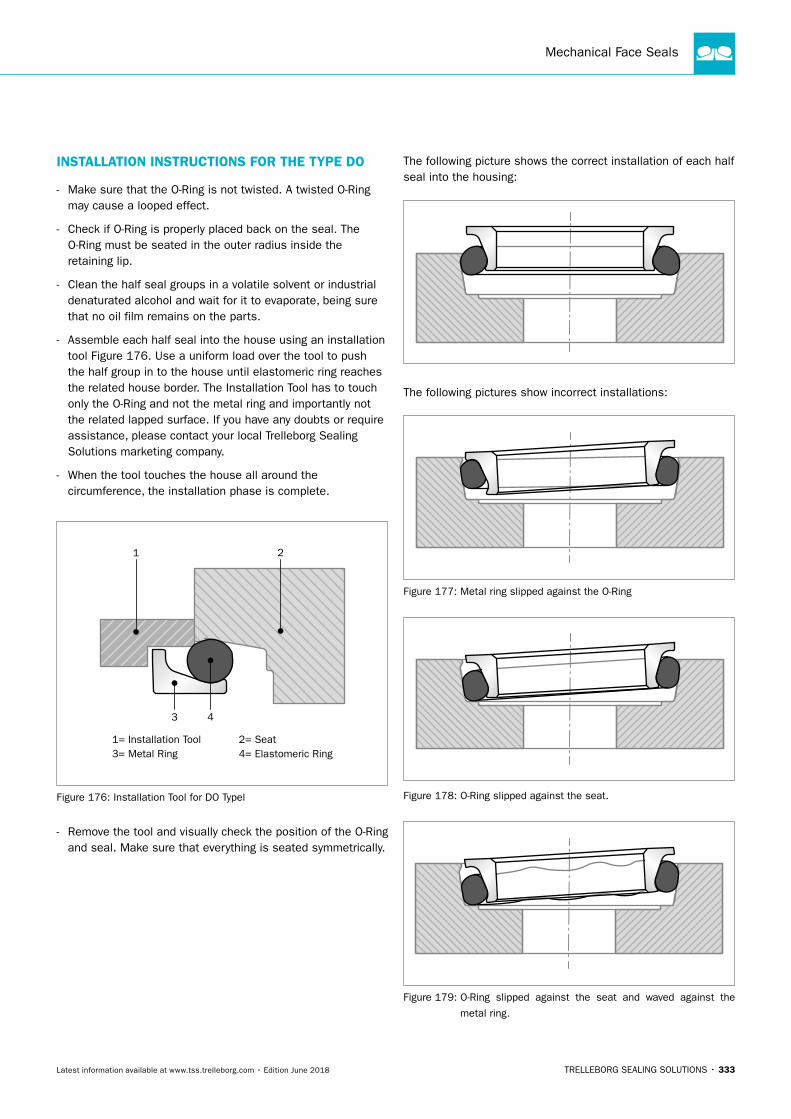
Mechanical Face Seals
TRELLEBORG SEALING SOLUTIONS • 333Latest information available at www.tss.trelleborg.com • Edition June 2018
INSTALLATION INSTRUCTIONS FOR THE TYPE DO
- Make sure that the O-Ring is not twisted. A twisted O-Ring may cause a looped effect.
- Check if O-Ring is properly placed back on the seal. The O-Ring must be seated in the outer radius inside the retaining lip.
- Clean the half seal groups in a volatile solvent or industrial denaturated alcohol and wait for it to evaporate, being sure that no oil film remains on the parts.
- Assemble each half seal into the house using an installation tool Figure 176. Use a uniform load over the tool to push the half group in to the house until elastomeric ring reaches the related house border. The Installation Tool has to touch only the O-Ring and not the metal ring and importantly not the related lapped surface. If you have any doubts or require assistance, please contact your local Trelleborg Sealing Solutions marketing company.
- When the tool touches the house all around the circumference, the installation phase is complete.
1= Installation Tool 2= Seat 4= Elastomeric Ring3= Metal Ring
21
3 4
Figure 176: Installation Tool for DO Typel
- Remove the tool and visually check the position of the O-Ring and seal. Make sure that everything is seated symmetrically.
The following picture shows the correct installation of each half seal into the housing:
The following pictures show incorrect installations:
Figure 177: Metal ring slipped against the O-Ring
Figure 178: O-Ring slipped against the seat.
Figure 179: O-Ring slipped against the seat and waved against the
metal ring.
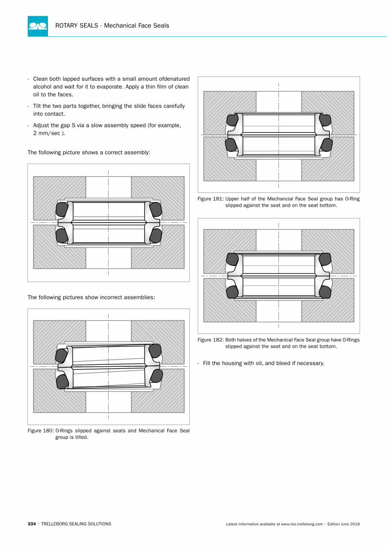
ROTARY SEALS · Mechanical Face Seals
334 • TRELLEBORG SEALING SOLUTIONS Latest information available at www.tss.trelleborg.com • Edition June 2018
- Clean both lapped surfaces with a small amount ofdenatured alcohol and wait for it to evaporate. Apply a thin film of clean oil to the faces.
- Tilt the two parts together, bringing the slide faces carefully into contact.
- Adjust the gap S via a slow assembly speed (for example, 2 mm/sec ).
The following picture shows a correct assembly:
The following pictures show incorrect assemblies:
Figure 180: O-Rings slipped against seats and Mechanical Face Seal group is tilted.
Figure 181: Upper half of the Mechancial Face Seal group has O-Ring slipped against the seat and on the seat bottom.
Figure 182: Both halves of the Mechanical Face Seal group have O-Rings slipped against the seat and on the seat bottom.
- Fill the housing with oil, and bleed if necessary.
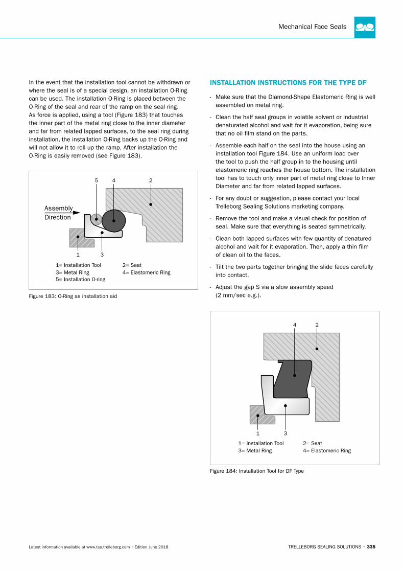
Mechanical Face Seals
TRELLEBORG SEALING SOLUTIONS • 335Latest information available at www.tss.trelleborg.com • Edition June 2018
In the event that the installation tool cannot be withdrawn or where the seal is of a special design, an installation O-Ring can be used. The installation O-Ring is placed between the O-Ring of the seal and rear of the ramp on the seal ring. As force is applied, using a tool (Figure 183) that touches the inner part of the metal ring close to the inner diameter and far from related lapped surfaces, to the seal ring during installation, the installation O-Ring backs up the O-Ring and will not allow it to roll up the ramp. After installation the O-Ring is easily removed (see Figure 183).
1= Installation Tool
5= Installation O-ring
2= Seat4= Elastomeric Ring3= Metal Ring
5 2
1 3
4
AssemblyDirection
Figure 183: O-Ring as installation aid
INSTALLATION INSTRUCTIONS FOR THE TYPE DF
- Make sure that the Diamond-Shape Elastomeric Ring is well assembled on metal ring.
- Clean the half seal groups in volatile solvent or industrial denaturated alcohol and wait for it evaporation, being sure that no oil film stand on the parts.
- Assemble each half on the seal into the house using an installation tool Figure 184. Use an uniform load over the tool to push the half group in to the housing until elastomeric ring reaches the house bottom. The installation tool has to touch only inner part of metal ring close to Inner Diameter and far from related lapped surfaces.
- For any doubt or suggestion, please contact your local Trelleborg Sealing Solutions marketing company.
- Remove the tool and make a visual check for position of seal. Make sure that everything is seated symmetrically.
- Clean both lapped surfaces with few quantity of denatured alcohol and wait for it evaporation. Then, apply a thin film of clean oil to the faces.
- Tilt the two parts together bringing the slide faces carefully into contact.
- Adjust the gap S via a slow assembly speed (2 mm/sec e.g.).
1= Installation Tool 2= Seat 4= Elastomeric Ring3= Metal Ring
2
1 3
4
Figure 184: Installation Tool for DF Type
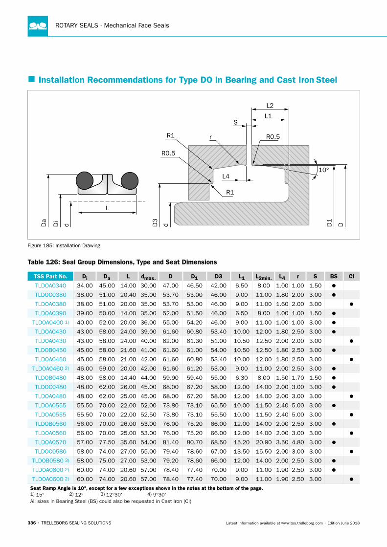
ROTARY SEALS · Mechanical Face Seals
336 • TRELLEBORG SEALING SOLUTIONS Latest information available at www.tss.trelleborg.com • Edition June 2018
� Installation Recommendations for Type DO in Bearing and Cast Iron Steel
DD1
dD3
Da
Di
d
L
10°
R1
L4
R1
L2
L1
R0.5
R0.5
S
r
Figure 185: Installation Drawing
Table 126: Seal Group Dimensions, Type and Seat Dimensions
TSS Part No. Di Da L dmax. D D1 D3 L1 L2min. L4 r S BS CI
TLDOA0340 34.00 45.00 14.00 30.00 47.00 46.50 42.00 6.50 8.00 1.00 1.00 1.50
TLDOC0380 38.00 51.00 20.40 35.00 53.70 53.00 46.00 9.00 11.00 1.80 2.00 3.00
TLDOA0380 38.00 51.00 20.00 35.00 53.70 53.00 46.00 9.00 11.00 1.60 2.00 3.00
TLDOA0390 39.00 50.00 14.00 35.00 52.00 51.50 46.00 6.50 8.00 1.00 1.00 1.50
TLDOA0400 1) 40.00 52.00 20.00 36.00 55.00 54.20 46.00 9.00 11.00 1.00 1.00 3.00
TLDOA0430 43.00 58.00 24.00 39.00 61.60 60.80 53.40 10.00 12.00 1.80 2.50 3.00
TLDOA0430 43.00 58.00 24.00 40.00 62.00 61.30 51.00 10.50 12.50 2.00 2.00 3.00
TLDOB0450 45.00 58.00 21.60 41.00 61.60 61.00 54.00 10.50 12.50 1.80 2.50 3.00
TLDOA0450 45.00 58.00 21.00 42.00 61.60 60.80 53.40 10.00 12.00 1.80 2.50 3.00
TLDOA0460 2) 46.00 59.00 20.00 42.00 61.60 61.20 53.00 9.00 11.00 2.00 2.50 3.00
TLDOB0480 48.00 58.00 14.40 44.00 59.90 59.40 55.00 6.30 8.00 1.50 1.70 1.50
TLDOC0480 48.00 62.00 26.00 45.00 68.00 67.20 58.00 12.00 14.00 2.00 3.00 3.00
TLDOA0480 48.00 62.00 25.00 45.00 68.00 67.20 58.00 12.00 14.00 2.00 3.00 3.00
TLDOA0555 55.50 70.00 22.00 52.00 73.80 73.10 65.50 10.00 11.50 2.40 5.00 3.00
TLDOA0555 55.50 70.00 22.00 52.50 73.80 73.10 55.50 10.00 11.50 2.40 5.00 3.00
TLDOB0560 56.00 70.00 26.00 53.00 76.00 75.20 66.00 12.00 14.00 2.00 2.50 3.00
TLDOA0560 56.00 70.00 25.00 53.00 76.00 75.20 66.00 12.00 14.00 2.00 3.00 3.00
TLDOA0570 57.00 77.50 35.60 54.00 81.40 80.70 68.50 15.20 20.90 3.50 4.80 3.00
TLDOC0580 58.00 74.00 27.00 55.00 79.40 78.60 67.00 13.50 15.50 2.00 3.00 3.00
TLDOB0580 3) 58.00 75.00 27.00 53.00 79.20 78.60 66.00 12.00 14.00 2.00 2.50 3.00
TLDOA0600 2) 60.00 74.00 20.60 57.00 78.40 77.40 70.00 9.00 11.00 1.90 2.50 3.00
TLDOA0600 2) 60.00 74.00 20.60 57.00 78.40 77.40 70.00 9.00 11.00 1.90 2.50 3.00
Seat Ramp Angle is 10°, except for a few exceptions shown in the notes at the bottom of the page. 1) 15° 2) 12° 3) 12°30' 4) 9°30' All sizes in Bearing Steel (BS) could also be requested in Cast Iron (CI)
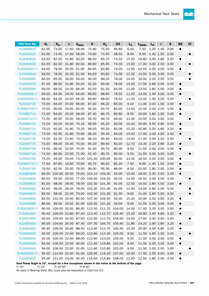
Mechanical Face Seals
TRELLEBORG SEALING SOLUTIONS • 337Latest information available at www.tss.trelleborg.com • Edition June 2018
TSS Part No. Di Da L dmax. D D1 D3 L1 L2min. L4 r S BS CI
TLDOB0610 61.00 73.00 17.60 58.00 75.80 75.50 66.80 6.50 7.50 1.00 1.40 3.00
TLDOA0610 61.00 73.00 17.60 58.00 75.80 75.50 68.50 8.00 9.50 1.40 1.50 2.00
TLDOB0635 63.50 82.50 31.80 60.50 86.50 85.70 73.50 15.20 16.80 3.50 4.80 3.20
TLDOA0635 63.50 82.50 31.80 60.50 86.80 85.90 74.00 15.00 17.00 3.00 2.50 3.00
TLDOA0640 2) 64.00 78.00 25.00 61.00 84.60 83.80 74.00 12.50 14.50 2.00 3.00 3.00
TLDOA0640 64.00 78.00 25.00 61.00 84.60 83.60 74.00 12.50 14.50 2.00 3.00 3.00
TLDOA0660 66.00 85.00 28.00 63.00 90.00 89.20 78.00 14.00 16.00 2.00 3.00 3.00
TLDOA0675 67.50 86.50 31.80 64.00 91.00 90.00 78.00 14.50 17.00 2.80 5.00 3.00
TLDOB0690 69.00 89.00 24.00 66.00 92.50 91.50 83.00 11.00 13.50 2.80 5.00 3.00
TLDOA0690 2) 69.00 84.00 24.00 66.00 89.60 88.60 78.50 11.00 13.00 1.90 3.00 3.00
TLDOA0690 2) 69.00 84.00 24.00 66.00 89.60 88.60 78.50 11.00 13.00 1.90 3.00 3.00
TLDOA0700 70.00 84.00 20.00 66.00 87.00 86.20 80.00 9.10 11.00 2.00 1.00 3.00
TLDOB0700 2) 70.00 90.00 29.00 65.00 95.50 94.70 84.00 13.50 15.50 2.00 3.00 3.00
TLDOB0710 71.00 84.00 20.00 68.00 87.40 86.70 80.80 8.50 10.00 1.80 2.00 3.00
TLDOA0710 2) 71.00 90.00 29.00 68.00 95.50 94.70 84.00 13.50 15.50 2.00 3.00 3.00
TLDOA0725 72.50 92.00 35.60 70.10 96.00 95.20 83.00 15.20 20.90 3.50 4.80 3.00
TLDOA0731 73.10 92.00 31.80 70.10 96.00 95.20 83.00 15.20 16.80 3.50 4.80 3.20
TLDOB0730 73.00 92.00 31.80 70.00 96.20 95.40 84.00 15.00 17.00 3.00 4.00 3.00
TLDOA0730 73.00 92.00 31.80 70.00 96.20 95.40 84.00 15.00 17.00 3.00 2.50 3.00
TLDOA0735 73.50 88.50 20.40 70.00 90.20 89.40 82.00 12.70 14.30 2.20 2.80 3.20
TLDOB0740 74.00 86.50 22.50 70.00 91.40 90.70 80.00 9.50 11.50 2.00 3.00 3.00
TLDOA0740 74.00 86.60 22.00 71.00 91.40 90.70 80.00 9.50 11.50 2.00 3.00 3.00
TLDOA0750 75.00 94.00 29.00 73.00 101.40 100.60 89.00 14.50 16.50 2.00 3.00 3.00
TLDOA0775 1) 77.50 87.60 13.60 75.90 90.70 90.20 85.20 7.50 8.00 1.40 1.50 3.00
TLDOA0795 79.50 92.50 20.00 76.00 96.00 95.30 88.00 8.50 10.50 1.80 2.00 3.00
TLDOB0800 80.00 100.00 30.00 76.00 104.10 103.30 93.00 15.00 18.00 2.30 2.50 3.00
TLDOA0800 80.50 99.50 29.00 77.00 105.00 104.20 92.00 14.50 16.50 2.00 3.00 3.00
TLDOA0810 81.00 98.00 28.00 78.00 102.30 101.30 91.00 12.50 14.50 2.80 5.00 3.00
TLDOA0810 81.00 98.00 28.00 78.00 102.30 101.30 91.00 12.50 14.50 2.80 5.00 3.00
TLDOA0820 82.00 98.00 22.00 79.00 102.30 101.30 91.00 9.00 11.00 2.80 5.00 3.00
TLDOA0825 82.50 102.00 35.60 80.50 107.30 106.50 94.30 15.20 20.90 3.50 4.80 3.20
TLDOA0860 86.00 99.00 20.00 81.00 102.00 101.20 94.00 9.00 11.50 2.00 3.00 3.00
TLDOC0900 2) 90.00 109.00 32.00 86.00 112.50 111.70 104.00 14.50 17.00 3.20 3.00 3.00
TLDOA0904 90.40 109.50 31.80 87.40 113.40 112.70 100.40 15.20 16.80 3.50 4.80 3.20
TLDOC0900 90.50 109.00 32.00 87.00 112.50 111.70 104.00 14.50 17.00 3.20 3.00 3.00
TLDOB0900 90.00 104.60 26.00 87.40 107.30 106.70 100.40 11.80 14.20 2.90 2.80 3.20
TLDOB0904 90.40 109.50 35.60 88.50 113.40 112.70 100.40 15.20 20.90 3.50 4.80 3.20
TLDOA0920 92.00 109.00 22.00 89.00 113.80 113.40 105.00 9.50 11.50 1.80 2.50 3.00
TLDOB0920 92.00 109.50 22.00 88.00 113.80 113.00 105.00 9.50 11.50 2.00 3.00 3.00
TLDOB0940 94.00 106.50 23.00 90.00 111.60 110.80 102.00 9.50 11.50 2.00 3.00 3.00
TLDOA0940 94.00 106.50 22.00 91.00 111.60 110.80 102.00 9.50 11.50 2.00 2.50 3.00
TLDOC0950 2) 95.00 114.00 32.00 91.00 120.00 119.20 107.00 15.00 17.00 2.50 3.00 3.00
TLDOA0950 95.00 111.00 24.00 92.00 115.60 114.80 108.00 11.00 12.50 1.80 2.00 3.00
Seat Ramp Angle is 10°, except for a few exceptions shown in the notes at the bottom of the page. 1) 15° 2) 12° 3) 12°30' 4) 9°30' All sizes in Bearing Steel (BS) could also be requested in Cast Iron (CI)
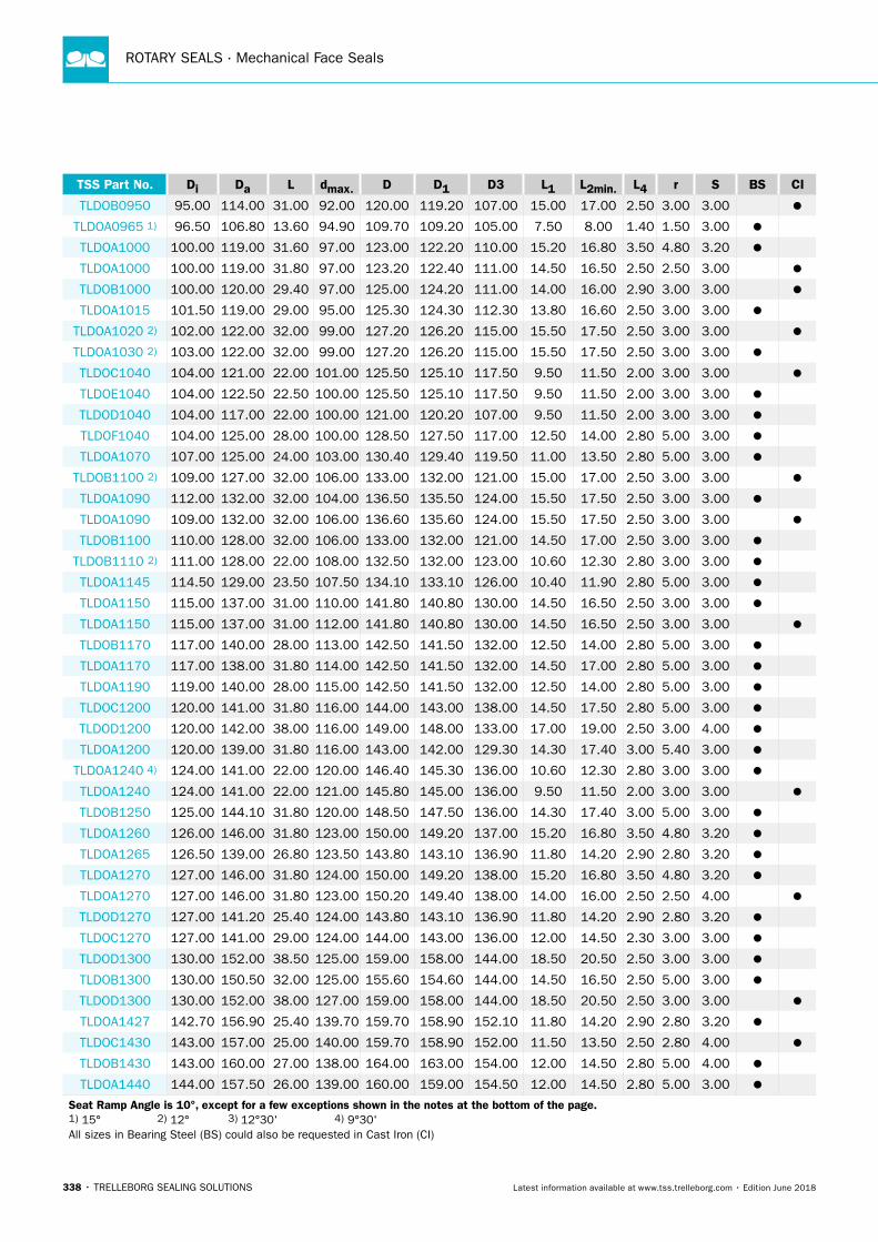
ROTARY SEALS · Mechanical Face Seals
338 • TRELLEBORG SEALING SOLUTIONS Latest information available at www.tss.trelleborg.com • Edition June 2018
TSS Part No. Di Da L dmax. D D1 D3 L1 L2min. L4 r S BS CI
TLDOB0950 95.00 114.00 31.00 92.00 120.00 119.20 107.00 15.00 17.00 2.50 3.00 3.00
TLDOA0965 1) 96.50 106.80 13.60 94.90 109.70 109.20 105.00 7.50 8.00 1.40 1.50 3.00
TLDOA1000 100.00 119.00 31.60 97.00 123.00 122.20 110.00 15.20 16.80 3.50 4.80 3.20
TLDOA1000 100.00 119.00 31.80 97.00 123.20 122.40 111.00 14.50 16.50 2.50 2.50 3.00
TLDOB1000 100.00 120.00 29.40 97.00 125.00 124.20 111.00 14.00 16.00 2.90 3.00 3.00
TLDOA1015 101.50 119.00 29.00 95.00 125.30 124.30 112.30 13.80 16.60 2.50 3.00 3.00
TLDOA1020 2) 102.00 122.00 32.00 99.00 127.20 126.20 115.00 15.50 17.50 2.50 3.00 3.00
TLDOA1030 2) 103.00 122.00 32.00 99.00 127.20 126.20 115.00 15.50 17.50 2.50 3.00 3.00
TLDOC1040 104.00 121.00 22.00 101.00 125.50 125.10 117.50 9.50 11.50 2.00 3.00 3.00
TLDOE1040 104.00 122.50 22.50 100.00 125.50 125.10 117.50 9.50 11.50 2.00 3.00 3.00
TLDOD1040 104.00 117.00 22.00 100.00 121.00 120.20 107.00 9.50 11.50 2.00 3.00 3.00
TLDOF1040 104.00 125.00 28.00 100.00 128.50 127.50 117.00 12.50 14.00 2.80 5.00 3.00
TLDOA1070 107.00 125.00 24.00 103.00 130.40 129.40 119.50 11.00 13.50 2.80 5.00 3.00
TLDOB1100 2) 109.00 127.00 32.00 106.00 133.00 132.00 121.00 15.00 17.00 2.50 3.00 3.00
TLDOA1090 112.00 132.00 32.00 104.00 136.50 135.50 124.00 15.50 17.50 2.50 3.00 3.00
TLDOA1090 109.00 132.00 32.00 106.00 136.60 135.60 124.00 15.50 17.50 2.50 3.00 3.00
TLDOB1100 110.00 128.00 32.00 106.00 133.00 132.00 121.00 14.50 17.00 2.50 3.00 3.00
TLDOB1110 2) 111.00 128.00 22.00 108.00 132.50 132.00 123.00 10.60 12.30 2.80 3.00 3.00
TLDOA1145 114.50 129.00 23.50 107.50 134.10 133.10 126.00 10.40 11.90 2.80 5.00 3.00
TLDOA1150 115.00 137.00 31.00 110.00 141.80 140.80 130.00 14.50 16.50 2.50 3.00 3.00
TLDOA1150 115.00 137.00 31.00 112.00 141.80 140.80 130.00 14.50 16.50 2.50 3.00 3.00
TLDOB1170 117.00 140.00 28.00 113.00 142.50 141.50 132.00 12.50 14.00 2.80 5.00 3.00
TLDOA1170 117.00 138.00 31.80 114.00 142.50 141.50 132.00 14.50 17.00 2.80 5.00 3.00
TLDOA1190 119.00 140.00 28.00 115.00 142.50 141.50 132.00 12.50 14.00 2.80 5.00 3.00
TLDOC1200 120.00 141.00 31.80 116.00 144.00 143.00 138.00 14.50 17.50 2.80 5.00 3.00
TLDOD1200 120.00 142.00 38.00 116.00 149.00 148.00 133.00 17.00 19.00 2.50 3.00 4.00
TLDOA1200 120.00 139.00 31.80 116.00 143.00 142.00 129.30 14.30 17.40 3.00 5.40 3.00
TLDOA1240 4) 124.00 141.00 22.00 120.00 146.40 145.30 136.00 10.60 12.30 2.80 3.00 3.00
TLDOA1240 124.00 141.00 22.00 121.00 145.80 145.00 136.00 9.50 11.50 2.00 3.00 3.00
TLDOB1250 125.00 144.10 31.80 120.00 148.50 147.50 136.00 14.30 17.40 3.00 5.00 3.00
TLDOA1260 126.00 146.00 31.80 123.00 150.00 149.20 137.00 15.20 16.80 3.50 4.80 3.20
TLDOA1265 126.50 139.00 26.80 123.50 143.80 143.10 136.90 11.80 14.20 2.90 2.80 3.20
TLDOA1270 127.00 146.00 31.80 124.00 150.00 149.20 138.00 15.20 16.80 3.50 4.80 3.20
TLDOA1270 127.00 146.00 31.80 123.00 150.20 149.40 138.00 14.00 16.00 2.50 2.50 4.00
TLDOD1270 127.00 141.20 25.40 124.00 143.80 143.10 136.90 11.80 14.20 2.90 2.80 3.20
TLDOC1270 127.00 141.00 29.00 124.00 144.00 143.00 136.00 12.00 14.50 2.30 3.00 3.00
TLDOD1300 130.00 152.00 38.50 125.00 159.00 158.00 144.00 18.50 20.50 2.50 3.00 3.00
TLDOB1300 130.00 150.50 32.00 125.00 155.60 154.60 144.00 14.50 16.50 2.50 5.00 3.00
TLDOD1300 130.00 152.00 38.00 127.00 159.00 158.00 144.00 18.50 20.50 2.50 3.00 3.00
TLDOA1427 142.70 156.90 25.40 139.70 159.70 158.90 152.10 11.80 14.20 2.90 2.80 3.20
TLDOC1430 143.00 157.00 25.00 140.00 159.70 158.90 152.00 11.50 13.50 2.50 2.80 4.00
TLDOB1430 143.00 160.00 27.00 138.00 164.00 163.00 154.00 12.00 14.50 2.80 5.00 4.00
TLDOA1440 144.00 157.50 26.00 139.00 160.00 159.00 154.50 12.00 14.50 2.80 5.00 3.00
Seat Ramp Angle is 10°, except for a few exceptions shown in the notes at the bottom of the page. 1) 15° 2) 12° 3) 12°30' 4) 9°30' All sizes in Bearing Steel (BS) could also be requested in Cast Iron (CI)
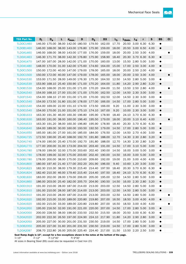
Mechanical Face Seals
TRELLEBORG SEALING SOLUTIONS • 339Latest information available at www.tss.trelleborg.com • Edition June 2018
TSS Part No. Di Da L dmax. D D1 D3 L1 L2min. L4 r S BS CI
TLDOC1460 146.00 175.00 38.00 142.00 180.50 179.50 162.00 17.70 20.50 3.00 6.30 6.30
TLDOB1460 146.00 168.00 38.00 143.00 176.80 175.90 159.00 18.00 20.50 3.00 6.50 4.00
TLDOA1460 146.00 168.00 38.00 143.00 177.00 176.00 159.00 18.00 20.00 2.50 3.00 4.00
TLDOA1463 146.30 171.70 38.00 142.30 176.80 175.90 158.90 18.40 20.30 3.70 6.30 6.30
TLDOA1470 147.00 167.00 28.00 142.00 171.00 170.00 160.00 13.00 15.50 2.80 5.00 3.00
TLDOA1480 148.00 170.00 31.00 142.00 175.60 174.60 164.00 15.00 17.00 2.50 3.00 4.00
TLDOC1500 150.00 172.00 40.00 147.00 179.00 178.00 165.00 18.00 20.00 2.50 2.00 4.00
TLDOC1500 150.00 172.00 40.00 147.00 179.00 178.00 165.00 18.00 20.00 2.50 3.00 4.00
TLDOA1530 153.00 171.50 28.00 149.00 176.30 175.30 164.50 12.50 14.50 2.80 5.00 3.00
TLDOA1539 153.90 168.10 25.40 150.90 171.00 170.20 164.00 11.80 14.20 2.90 2.80 3.20
TLDOB1530 154.00 168.00 25.00 151.00 171.00 170.20 164.00 11.50 13.50 2.50 2.80 4.00
TLDOA1540 154.00 168.10 27.00 151.00 171.00 170.00 162.50 12.00 14.50 2.30 3.00 3.00
TLDOF1540 154.00 168.10 27.00 151.00 171.00 170.00 162.50 12.00 14.50 2.30 3.00 3.00
TLDOC1540 154.00 173.50 31.80 151.00 178.00 177.00 166.00 14.50 17.00 2.80 5.00 3.00
TLDOD1540 154.00 169.00 22.00 151.10 174.50 173.50 166.00 9.20 11.00 2.30 3.00 3.00
TLDOE1540 154.00 170.00 21.00 151.00 175.10 174.10 167.00 9.20 10.00 2.30 3.00 3.00
TLDOB1633 163.30 191.30 46.00 160.30 196.80 195.90 178.90 18.40 24.10 3.70 6.30 6.30
TLDOB1630 163.00 191.00 38.00 160.00 196.40 195.50 179.00 18.00 20.00 3.10 6.40 4.00
TLDOA1633 163.30 191.20 38.00 160.30 196.80 195.90 178.90 18.40 20.30 3.70 6.30 6.30
TLDOA1640 164.00 189.00 30.00 160.00 193.50 192.50 179.00 14.50 17.00 2.80 5.00 3.00
TLDOA1650 165.00 181.00 27.00 161.00 185.00 184.00 176.50 12.00 14.50 2.70 4.00 3.00
TLDOA1725 172.50 190.00 25.40 168.00 192.70 191.80 188.00 12.70 14.30 2.30 2.80 3.20
TLDOA1740 174.00 190.00 25.40 170.00 192.70 191.80 188.00 12.70 14.30 2.30 2.80 3.20
TLDOA1770 177.00 200.00 31.00 173.00 204.50 203.40 191.00 14.50 17.00 3.10 5.00 3.00
TLDOA1780 178.00 199.00 32.00 175.00 203.60 202.40 190.00 14.50 16.00 3.00 5.00 3.00
TLDOC1780 178.00 199.00 32.00 175.00 203.60 202.40 190.00 14.50 16.00 3.00 5.00 3.00
TLDOB1780 178.00 200.00 38.00 175.00 210.60 209.60 192.00 19.00 21.00 3.00 4.00 4.00
TLDOA1800 180.00 197.40 21.40 177.00 202.20 201.90 196.00 9.40 10.60 1.20 3.00 3.00
TLDOA1823 182.30 210.30 38.00 179.30 215.40 214.40 197.50 18.40 20.30 3.70 6.30 6.30
TLDOA1824 182.40 210.30 46.00 179.40 215.40 214.40 197.50 18.40 24.10 3.70 6.30 6.30
TLDOB1830 183.00 202.00 28.00 179.00 206.00 205.00 195.00 12.50 14.50 2.80 5.00 3.00
TLDOA1860 186.00 203.00 25.40 182.00 205.70 204.90 190.50 14.50 16.00 2.30 2.80 3.20
TLDOD1910 191.00 210.00 28.00 187.00 214.00 213.00 203.00 12.50 14.50 2.80 5.00 3.00
TLDOA1910 191.00 210.00 28.00 187.00 214.00 213.00 203.00 12.50 14.50 2.80 5.00 3.00
TLDOA1910 191.00 210.00 28.00 187.00 214.00 213.00 203.00 12.50 14.50 2.80 5.00 3.00
TLDOA1920 192.00 215.00 33.00 189.00 220.80 219.80 207.00 16.50 18.50 3.00 4.00 4.00
TLDOA1920 192.00 215.00 33.00 189.00 220.80 219.80 207.00 16.50 18.50 3.00 4.00 4.00
TLDOA1950 195.00 216.50 32.00 191.00 221.00 220.00 207.00 14.50 17.00 2.80 5.00 3.00
TLDOA2000 200.00 228.50 38.00 196.00 233.50 232.50 215.50 18.00 20.50 3.00 6.30 6.30
TLDOA2020 202.00 222.30 26.50 197.00 224.90 224.10 217.90 11.80 14.20 2.90 2.80 3.00
TLDOA2050 205.00 227.00 30.00 201.00 231.50 230.50 219.00 14.50 17.00 2.80 5.00 3.00
TLDOB2050 205.00 227.00 31.60 201.00 231.50 230.50 219.00 14.50 17.00 2.80 5.00 3.00
TLDOA2087 208.70 222.80 26.00 205.00 225.40 224.40 217.00 11.50 13.50 2.20 2.50 3.00
Seat Ramp Angle is 10°, except for a few exceptions shown in the notes at the bottom of the page. 1) 15° 2) 12° 3) 12°30' 4) 9°30' All sizes in Bearing Steel (BS) could also be requested in Cast Iron (CI)
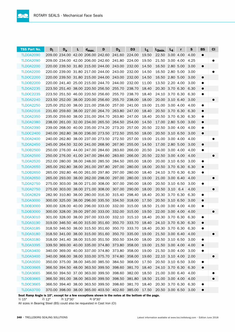
ROTARY SEALS · Mechanical Face Seals
340 • TRELLEBORG SEALING SOLUTIONS Latest information available at www.tss.trelleborg.com • Edition June 2018
TSS Part No. Di Da L dmax. D D1 D3 L1 L2min. L4 r S BS CI
TLDOA2090 209.00 234.00 42.00 206.00 242.60 241.60 224.00 19.50 22.50 3.00 4.00 4.00
TLDOA2090 209.00 234.00 42.00 206.00 242.60 241.80 224.00 19.50 21.50 3.00 4.00 4.25
TLDOA2200 220.00 239.50 31.80 215.00 244.00 243.00 232.00 14.50 16.50 2.80 5.00 3.00
TLDOA2200 220.00 239.00 31.80 217.00 244.00 243.00 232.00 14.50 16.50 2.80 5.00 3.00
TLDOC2200 220.00 239.50 31.80 215.00 244.00 243.00 232.00 14.50 16.50 2.80 5.00 3.00
TLDOB2200 220.00 241.40 25.00 215.00 244.70 244.00 232.00 11.00 13.50 2.20 4.00 3.00
TLDOA2235 223.50 251.40 38.00 220.50 256.50 255.70 238.70 18.40 20.30 3.70 6.30 6.30
TLDOC2235 223.50 251.50 46.00 220.50 256.60 255.70 238.70 18.40 24.10 3.70 6.30 6.30
TLDOA2240 223.50 252.00 38.00 220.00 256.60 255.70 238.00 18.00 20.00 3.10 6.40 3.00
TLDOA2250 225.00 252.00 38.00 221.00 258.00 257.00 241.00 19.00 21.00 3.00 4.00 4.00
TLDOA2316 231.60 259.60 38.00 227.00 264.70 263.80 247.00 18.40 20.50 3.70 6.30 6.30
TLDOA2350 235.00 259.60 38.00 231.00 264.70 263.80 247.00 18.40 20.50 3.70 6.30 6.30
TLDOA2380 238.00 261.00 32.00 234.00 265.50 264.50 254.00 14.50 17.00 2.80 5.00 3.00
TLDOA2390 239.00 268.00 40.00 235.00 274.20 273.20 257.00 20.50 22.50 3.00 4.00 4.00
TLDOC2400 240.00 262.80 38.00 236.00 273.50 272.50 255.50 18.00 20.50 3.10 6.50 3.00
TLDOA2400 240.00 262.80 38.00 237.00 273.50 272.50 257.00 19.00 21.00 3.00 4.00 4.00
TLDOA2450 245.00 264.50 32.00 241.00 268.90 267.90 255.00 14.50 17.00 2.80 5.00 3.00
TLDOB2500 250.00 276.00 44.00 247.00 284.60 283.60 266.00 20.50 24.00 3.00 4.00 4.00
TLDOA2500 250.00 276.00 41.00 247.00 284.60 283.60 266.00 20.50 22.50 3.00 4.00 4.00
TLDOA2520 252.00 280.00 38.00 248.00 285.50 284.50 265.00 18.00 20.00 3.10 6.50 3.00
TLDOA2650 265.00 292.80 38.00 261.00 297.80 297.00 280.00 18.00 20.50 3.70 6.30 6.30
TLDOB2650 265.00 292.80 46.00 261.00 297.80 297.00 280.00 18.40 24.10 3.70 6.30 6.30
TLDOA2650 265.00 293.00 38.00 262.00 298.00 297.00 280.00 19.00 21.00 3.00 6.40 4.00
TLDOA2750 275.00 303.00 38.00 271.00 308.00 307.00 290.00 18.00 20.50 3.10 6.50 3.00
TLDOA2750 275.00 303.00 38.00 271.00 308.00 307.00 290.00 18.00 20.50 3.10 6.4 4.00
TLDOA2829 282.90 310.80 38.00 280.00 316.30 315.40 298.40 18.40 20.30 3.70 6.30 6.30
TLDOA3000 300.00 325.00 38.00 296.00 335.50 334.50 318.00 17.50 20.50 3.10 6.50 3.00
TLDOB3000 300.00 328.00 40.00 296.00 333.00 332.00 315.00 18.50 21.00 3.00 4.00 4.00
TLDOB3000 300.00 328.00 39.00 297.00 333.00 332.00 315.00 19.50 22.00 3.00 4.00 4.00
TLDOA3010 301.00 328.00 38.00 297.00 333.00 332.10 315.10 18.40 20.30 3.70 6.30 6.30
TLDOA3190 319.00 346.50 46.00 315.00 351.60 350.70 333.70 18.40 24.10 3.70 6.30 6.30
TLDOA3185 318.50 346.50 38.00 315.50 351.60 350.70 333.70 18.40 20.30 3.70 6.30 6.30
TLDOA3180 318.50 341.00 38.00 315.00 351.60 350.70 335.00 19.00 21.50 3.00 6.40 4.00
TLDOA3180 318.00 341.40 38.00 315.00 351.50 350.50 334.00 18.00 20.50 3.10 6.50 3.00
TLDOA3395 339.50 369.00 40.00 335.00 374.80 373.80 358.00 19.00 21.50 3.00 4.00 4.00
TLDOA3400 340.00 369.00 40.00 337.00 374.80 373.80 358.00 19.00 21.50 3.00 4.00 3.00
TLDOA3400 340.00 368.00 38.00 333.00 375.70 374.80 358.00 19.60 22.10 3.10 4.00 2.00
TLDOA3500 350.00 375.00 38.00 345.00 385.50 384.50 368.00 17.50 20.50 3.10 6.50 3.00
TLDOD3665 366.50 394.50 48.00 363.50 399.50 398.60 381.70 18.40 24.10 3.70 6.30 6.30
TLDOA3665 366.50 394.50 37.00 363.00 399.50 398.60 382.00 18.50 21.00 3.00 6.40 4.00
TLDOB3665 366.50 391.00 38.00 363.00 399.50 398.50 381.80 18.50 21.00 3.00 4.00 4.00
TLDOC3665 366.50 394.40 38.00 363.50 399.50 398.60 381.70 18.40 20.30 3.70 6.30 6.30
TLDOA3700 370.00 398.00 38.00 365.00 403.50 402.60 385.00 17.50 20.50 3.00 6.50 3.00
Seat Ramp Angle is 10°, except for a few exceptions shown in the notes at the bottom of the page. 1) 15° 2) 12° 3) 12°30' 4) 9°30' All sizes in Bearing Steel (BS) could also be requested in Cast Iron (CI)
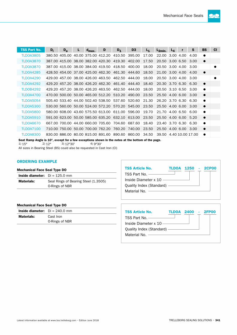
Mechanical Face Seals
TRELLEBORG SEALING SOLUTIONS • 341Latest information available at www.tss.trelleborg.com • Edition June 2018
TSS Part No. Di Da L dmax. D D1 D3 L1 L2min. L4 r S BS CI
TLDOA3805 380.50 405.00 40.00 375.00 412.20 410.50 395.00 17.00 22.00 3.00 4.00 4.00
TLDOA3870 387.00 415.00 38.00 382.00 420.30 419.30 402.00 17.50 20.50 3.00 6.50 3.00
TLDOA3870 387.00 415.00 38.00 384.00 419.50 418.50 400.00 18.00 20.50 3.00 4.00 3.00
TLDOA4285 428.50 454.00 37.00 425.00 462.30 461.30 444.60 18.50 21.00 3.00 4.00 4.00
TLDOA4290 429.00 457.00 38.00 426.00 463.50 462.50 444.00 18.00 20.50 3.00 4.00 3.00
TLDOA4292 429.20 457.20 38.00 426.20 462.30 461.40 444.40 18.40 20.30 3.70 6.30 6.30
TLDOB4292 429.20 457.20 38.00 426.20 463.50 462.50 444.00 18.00 20.50 3.10 6.50 3.00
TLDOA4700 470.00 500.00 50.00 465.00 512.20 510.20 490.00 23.50 25.50 4.00 6.00 3.00
TLDOA5054 505.40 533.40 44.00 502.40 538.50 537.60 520.60 21.30 26.20 3.70 6.30 6.30
TLDOA5300 530.00 560.00 50.00 524.00 572.20 570.20 545.00 23.50 25.50 4.00 6.00 3.00
TLDOA5800 580.00 608.00 43.60 575.50 613.00 611.00 596.00 19.70 21.70 4.00 6.50 6.00
TLDOA5910 591.00 623.00 50.00 585.00 635.20 632.10 613.00 23.50 25.50 4.00 6.00 5.20
TLDOA6670 667.00 700.00 44.00 660.00 705.60 704.60 687.60 18.40 23.40 3.70 6.30 6.30
TLDOA7100 710.00 750.00 50.00 700.00 762.20 760.20 740.00 23.50 25.50 4.00 6.00 3.00
TLDOA8300 830.00 886.00 80.00 815.00 891.60 890.60 860.00 34.50 39.50 4.40 10.00 17.00
Seat Ramp Angle is 10°, except for a few exceptions shown in the notes at the bottom of the page. 1) 15° 2) 12° 3) 12°30' 4) 9°30' All sizes in Bearing Steel (BS) could also be requested in Cast Iron (CI)
ORDERING EXAMPLE
Mechanical Face Seal Type DO
Inside diameter: Di = 125.0 mm
Materials: Seal Rings of Bearing Steel (1.3505) O-Rings of NBR
Mechanical Face Seal Type DO
Inside diameter: Di = 240.0 mm
Materials: Cast Iron O-Rings of NBR
Quality Index (Standard)
TSS Part No.
TSS Article No. TLDOA - 2CP001250
Inside Diameter x 10
Material No.
Quality Index (Standard)
TSS Part No.
TSS Article No. TLDOA - 2FP002400
Inside Diameter x 10
Material No.
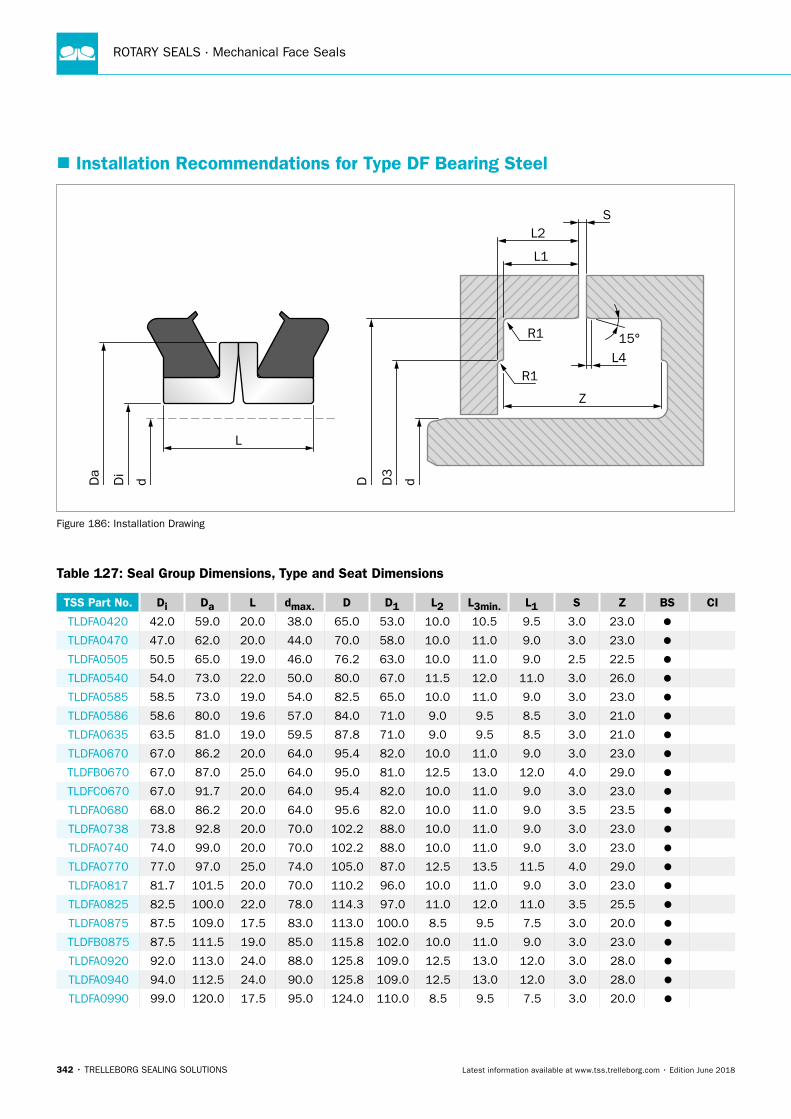
ROTARY SEALS · Mechanical Face Seals
342 • TRELLEBORG SEALING SOLUTIONS Latest information available at www.tss.trelleborg.com • Edition June 2018
� Installation Recommendations for Type DF Bearing Steel
Da
d dDi
D3
D
15°
S
L4R1
R1
L2
L1
Z
L
Figure 186: Installation Drawing
Table 127: Seal Group Dimensions, Type and Seat Dimensions
TSS Part No. Di Da L dmax. D D1 L2 L3min. L1 S Z BS CI
TLDFA0420 42.0 59.0 20.0 38.0 65.0 53.0 10.0 10.5 9.5 3.0 23.0
TLDFA0470 47.0 62.0 20.0 44.0 70.0 58.0 10.0 11.0 9.0 3.0 23.0
TLDFA0505 50.5 65.0 19.0 46.0 76.2 63.0 10.0 11.0 9.0 2.5 22.5
TLDFA0540 54.0 73.0 22.0 50.0 80.0 67.0 11.5 12.0 11.0 3.0 26.0
TLDFA0585 58.5 73.0 19.0 54.0 82.5 65.0 10.0 11.0 9.0 3.0 23.0
TLDFA0586 58.6 80.0 19.6 57.0 84.0 71.0 9.0 9.5 8.5 3.0 21.0
TLDFA0635 63.5 81.0 19.0 59.5 87.8 71.0 9.0 9.5 8.5 3.0 21.0
TLDFA0670 67.0 86.2 20.0 64.0 95.4 82.0 10.0 11.0 9.0 3.0 23.0
TLDFB0670 67.0 87.0 25.0 64.0 95.0 81.0 12.5 13.0 12.0 4.0 29.0
TLDFC0670 67.0 91.7 20.0 64.0 95.4 82.0 10.0 11.0 9.0 3.0 23.0
TLDFA0680 68.0 86.2 20.0 64.0 95.6 82.0 10.0 11.0 9.0 3.5 23.5
TLDFA0738 73.8 92.8 20.0 70.0 102.2 88.0 10.0 11.0 9.0 3.0 23.0
TLDFA0740 74.0 99.0 20.0 70.0 102.2 88.0 10.0 11.0 9.0 3.0 23.0
TLDFA0770 77.0 97.0 25.0 74.0 105.0 87.0 12.5 13.5 11.5 4.0 29.0
TLDFA0817 81.7 101.5 20.0 70.0 110.2 96.0 10.0 11.0 9.0 3.0 23.0
TLDFA0825 82.5 100.0 22.0 78.0 114.3 97.0 11.0 12.0 11.0 3.5 25.5
TLDFA0875 87.5 109.0 17.5 83.0 113.0 100.0 8.5 9.5 7.5 3.0 20.0
TLDFB0875 87.5 111.5 19.0 85.0 115.8 102.0 10.0 11.0 9.0 3.0 23.0
TLDFA0920 92.0 113.0 24.0 88.0 125.8 109.0 12.5 13.0 12.0 3.0 28.0
TLDFA0940 94.0 112.5 24.0 90.0 125.8 109.0 12.5 13.0 12.0 3.0 28.0
TLDFA0990 99.0 120.0 17.5 95.0 124.0 110.0 8.5 9.5 7.5 3.0 20.0
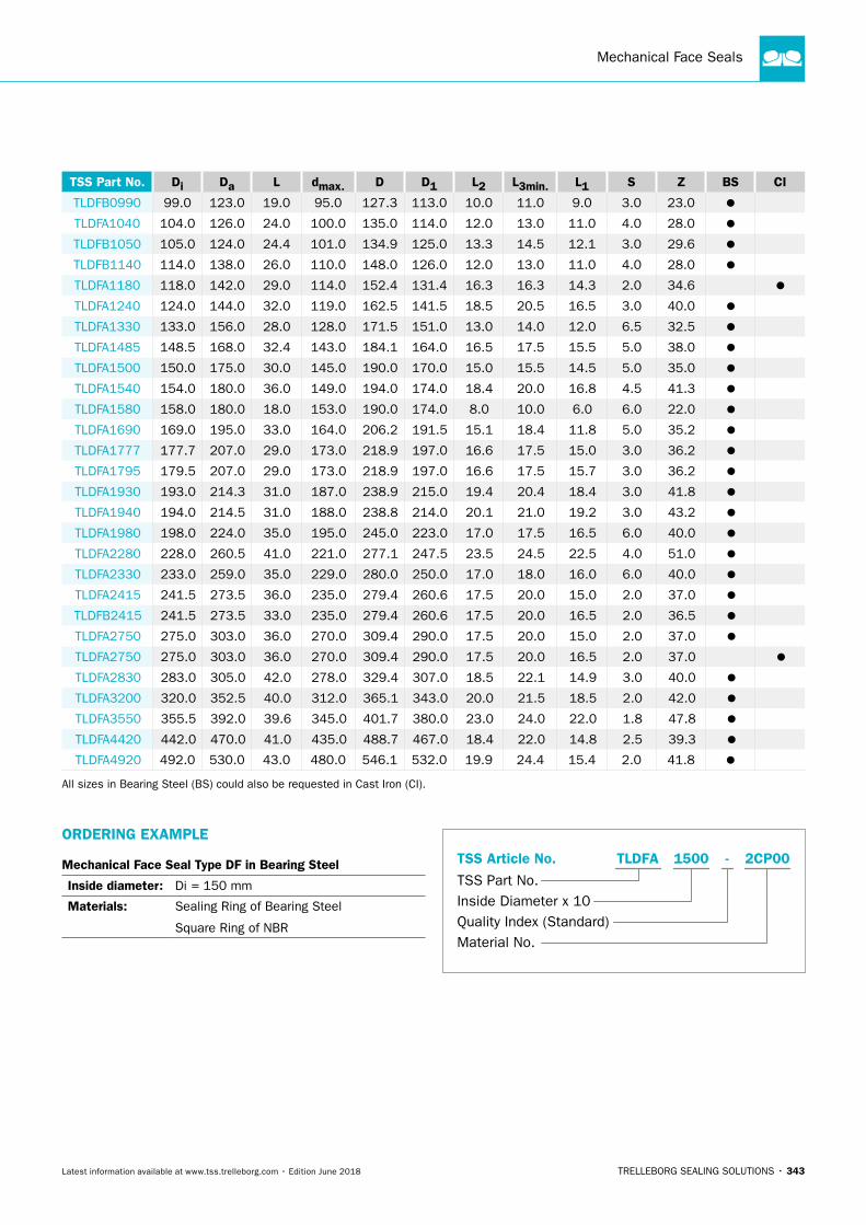
Mechanical Face Seals
TRELLEBORG SEALING SOLUTIONS • 343Latest information available at www.tss.trelleborg.com • Edition June 2018
TSS Part No. Di Da L dmax. D D1 L2 L3min. L1 S Z BS CI
TLDFB0990 99.0 123.0 19.0 95.0 127.3 113.0 10.0 11.0 9.0 3.0 23.0
TLDFA1040 104.0 126.0 24.0 100.0 135.0 114.0 12.0 13.0 11.0 4.0 28.0
TLDFB1050 105.0 124.0 24.4 101.0 134.9 125.0 13.3 14.5 12.1 3.0 29.6
TLDFB1140 114.0 138.0 26.0 110.0 148.0 126.0 12.0 13.0 11.0 4.0 28.0
TLDFA1180 118.0 142.0 29.0 114.0 152.4 131.4 16.3 16.3 14.3 2.0 34.6
TLDFA1240 124.0 144.0 32.0 119.0 162.5 141.5 18.5 20.5 16.5 3.0 40.0
TLDFA1330 133.0 156.0 28.0 128.0 171.5 151.0 13.0 14.0 12.0 6.5 32.5
TLDFA1485 148.5 168.0 32.4 143.0 184.1 164.0 16.5 17.5 15.5 5.0 38.0
TLDFA1500 150.0 175.0 30.0 145.0 190.0 170.0 15.0 15.5 14.5 5.0 35.0
TLDFA1540 154.0 180.0 36.0 149.0 194.0 174.0 18.4 20.0 16.8 4.5 41.3
TLDFA1580 158.0 180.0 18.0 153.0 190.0 174.0 8.0 10.0 6.0 6.0 22.0
TLDFA1690 169.0 195.0 33.0 164.0 206.2 191.5 15.1 18.4 11.8 5.0 35.2
TLDFA1777 177.7 207.0 29.0 173.0 218.9 197.0 16.6 17.5 15.0 3.0 36.2
TLDFA1795 179.5 207.0 29.0 173.0 218.9 197.0 16.6 17.5 15.7 3.0 36.2
TLDFA1930 193.0 214.3 31.0 187.0 238.9 215.0 19.4 20.4 18.4 3.0 41.8
TLDFA1940 194.0 214.5 31.0 188.0 238.8 214.0 20.1 21.0 19.2 3.0 43.2
TLDFA1980 198.0 224.0 35.0 195.0 245.0 223.0 17.0 17.5 16.5 6.0 40.0
TLDFA2280 228.0 260.5 41.0 221.0 277.1 247.5 23.5 24.5 22.5 4.0 51.0
TLDFA2330 233.0 259.0 35.0 229.0 280.0 250.0 17.0 18.0 16.0 6.0 40.0
TLDFA2415 241.5 273.5 36.0 235.0 279.4 260.6 17.5 20.0 15.0 2.0 37.0
TLDFB2415 241.5 273.5 33.0 235.0 279.4 260.6 17.5 20.0 16.5 2.0 36.5
TLDFA2750 275.0 303.0 36.0 270.0 309.4 290.0 17.5 20.0 15.0 2.0 37.0
TLDFA2750 275.0 303.0 36.0 270.0 309.4 290.0 17.5 20.0 16.5 2.0 37.0
TLDFA2830 283.0 305.0 42.0 278.0 329.4 307.0 18.5 22.1 14.9 3.0 40.0
TLDFA3200 320.0 352.5 40.0 312.0 365.1 343.0 20.0 21.5 18.5 2.0 42.0
TLDFA3550 355.5 392.0 39.6 345.0 401.7 380.0 23.0 24.0 22.0 1.8 47.8
TLDFA4420 442.0 470.0 41.0 435.0 488.7 467.0 18.4 22.0 14.8 2.5 39.3
TLDFA4920 492.0 530.0 43.0 480.0 546.1 532.0 19.9 24.4 15.4 2.0 41.8
All sizes in Bearing Steel (BS) could also be requested in Cast Iron (CI).
ORDERING EXAMPLE
Mechanical Face Seal Type DF in Bearing Steel
Inside diameter: Di = 150 mm
Materials: Sealing Ring of Bearing Steel
Square Ring of NBR
Quality Index (Standard)
TSS Part No.
TSS Article No. TLDFA - 2CP001500
Inside Diameter x 10
Material No.

ROTARY SEALS · Mechanical Face Seals
344 • TRELLEBORG SEALING SOLUTIONS Latest information available at www.tss.trelleborg.com • Edition June 2018

TRELLEBORG SEALING SOLUTIONS • 345Latest information available at www.tss.trelleborg.com • Edition June 2018
StorageAdvice
ROTARY SEALS · Storage Advice
346 • TRELLEBORG SEALING SOLUTIONS Latest information available at www.tss.trelleborg.com • Edition June 2018
Storage Advice
TRELLEBORG SEALING SOLUTIONS • 347Latest information available at www.tss.trelleborg.com • Edition June 2018
The cost-effective use of seals and bearings is highly influenced by the quality criteria applied in production. Seals and bearings from Trelleborg Sealing Solutions are continuously monitored according to strict quality standards from material acquisition through to delivery.
Certification of our production plants in accordance with international standards QS 9000/ISO 9000 meets the specific requirements for quality control and management of purchasing, production and marketing functions.
Our quality policy is consistently controlled by strict procedures and guidelines which are implemented within all strategic areas of the company.
All testing of materials and products is performed in accordance with accepted test standards and specifications, e.g. random sample testing in accordance with ISO 2859-1:2004-01 AQL 1,0 general inspection level II, normal inspection.
Inspection specifications correspond to standards applicable to individual product groups (e.g. for O-Rings: ISO 3601).Our sealing materials are produced free of chlorofluorinated hydrocarbons and carcinogenic elements.
� Guidelines for the Storage of Polymer Products Based on ISO 2230
Many polymer products and components are stored for long periods of time before being put into service, so it is important they are stored in conditions that minimize unwanted changes in properties. Such changes may result from degradation, in which case they may include excessive hardening, softening, cracking, crazing and other surface effects. Other changes may be caused by deformation, contamination or mechanical damage.
PackagingUnless otherwise specified in the appropriate product specification, rubber products should be enclosed in individual sealed envelopes. The packaging should be carried out in an atmosphere in which the relative humidity is less than 70%, or if polyurethanes are being packed, less than 65%. Where there is serious risk of ingress of moisture (e.g. rubber-metal-bonded parts), aluminum foil/paper/polyethylene laminate or other similar means of protection should be used to ensure protection from ingress of moisture.
TemperatureThe storage temperature should be below +25 °C and the products should be stored away from direct sources of heat such as boilers, radiators and direct sunlight. If the storage temperature is below +15 °C, care should be exercised during handling of stored products, as they may have stiffened and have become susceptible to distortion if not handled carefully.
HumidityThe relative humidity should be such that, given in the variations of temperature in storage, condensation does not occur. In all cases, the relative humidity of the atmosphere in storage should be less than 70%, or if polyurethanes are being stored, less than 65%.
LightRubber should be protected from light sources, in particular direct sunlight or intense light having a high ultra-violet content. It is advisable that any windows of storage rooms be covered with a red or orange coating or screen.
RadiationPrecautions should be taken to protect stored products from all sources of ionizing radiation likely to cause damage to the products.
OzoneOzone has a particularly harmful effect on rubber. Storage rooms should not contain any equipment that is capable of generating ozone, such as mercury vapor lamps or highvoltage electrical equipment giving rise to electric sparks or electrical discharges. Combustion gases and organic vapors should also be excluded, as they may give rise to ozone via photo-chemical processes. When equipment such as a fork-lift truck is used to handle large rubber products, care needs to be taken to ensure this equipment is not a source of pollution that may affect the rubber. Combustion gases should be considered separately. While they are responsible for generating ground-level ozone, they may also contain unburned fuel which, by condensing on rubber products, can cause additional deterioration.
� General Quality Criteria
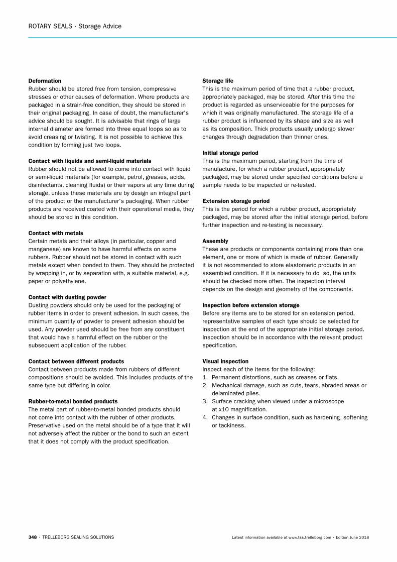
ROTARY SEALS · Storage Advice
348 • TRELLEBORG SEALING SOLUTIONS Latest information available at www.tss.trelleborg.com • Edition June 2018
DeformationRubber should be stored free from tension, compressive stresses or other causes of deformation. Where products are packaged in a strain-free condition, they should be stored in their original packaging. In case of doubt, the manufacturer's advice should be sought. It is advisable that rings of large internal diameter are formed into three equal loops so as to avoid creasing or twisting. It is not possible to achieve this condition by forming just two loops.
Contact with liquids and semi-liquid materialsRubber should not be allowed to come into contact with liquid or semi-liquid materials (for example, petrol, greases, acids, disinfectants, cleaning fluids) or their vapors at any time during storage, unless these materials are by design an integral part of the product or the manufacturer's packaging. When rubber products are received coated with their operational media, they should be stored in this condition.
Contact with metalsCertain metals and their alloys (in particular, copper and manganese) are known to have harmful effects on some rubbers. Rubber should not be stored in contact with such metals except when bonded to them. They should be protected by wrapping in, or by separation with, a suitable material, e.g. paper or polyethylene.
Contact with dusting powderDusting powders should only be used for the packaging of rubber items in order to prevent adhesion. In such cases, the minimum quantity of powder to prevent adhesion should be used. Any powder used should be free from any constituent that would have a harmful effect on the rubber or the subsequent application of the rubber.
Contact between different productsContact between products made from rubbers of different compositions should be avoided. This includes products of the same type but differing in color.
Rubber-to-metal bonded productsThe metal part of rubber-to-metal bonded products should not come into contact with the rubber of other products. Preservative used on the metal should be of a type that it will not adversely affect the rubber or the bond to such an extent that it does not comply with the product specification.
Storage lifeThis is the maximum period of time that a rubber product, appropriately packaged, may be stored. After this time the product is regarded as unserviceable for the purposes for which it was originally manufactured. The storage life of a rubber product is influenced by its shape and size as well as its composition. Thick products usually undergo slower changes through degradation than thinner ones.
Initial storage periodThis is the maximum period, starting from the time of manufacture, for which a rubber product, appropriately packaged, may be stored under specified conditions before a sample needs to be inspected or re-tested.
Extension storage periodThis is the period for which a rubber product, appropriately packaged, may be stored after the initial storage period, before further inspection and re-testing is necessary.
AssemblyThese are products or components containing more than one element, one or more of which is made of rubber. Generally it is not recommended to store elastomeric products in an assembled condition. If it is necessary to do so, the units should be checked more often. The inspection interval depends on the design and geometry of the components.
Inspection before extension storageBefore any items are to be stored for an extension period, representative samples of each type should be selected for inspection at the end of the appropriate initial storage period. Inspection should be in accordance with the relevant product specification.
Visual inspectionInspect each of the items for the following:1. Permanent distortions, such as creases or flats.2. Mechanical damage, such as cuts, tears, abraded areas or
delaminated plies.3. Surface cracking when viewed under a microscope
at x10 magnification.4. Changes in surface condition, such as hardening, softening
or tackiness.
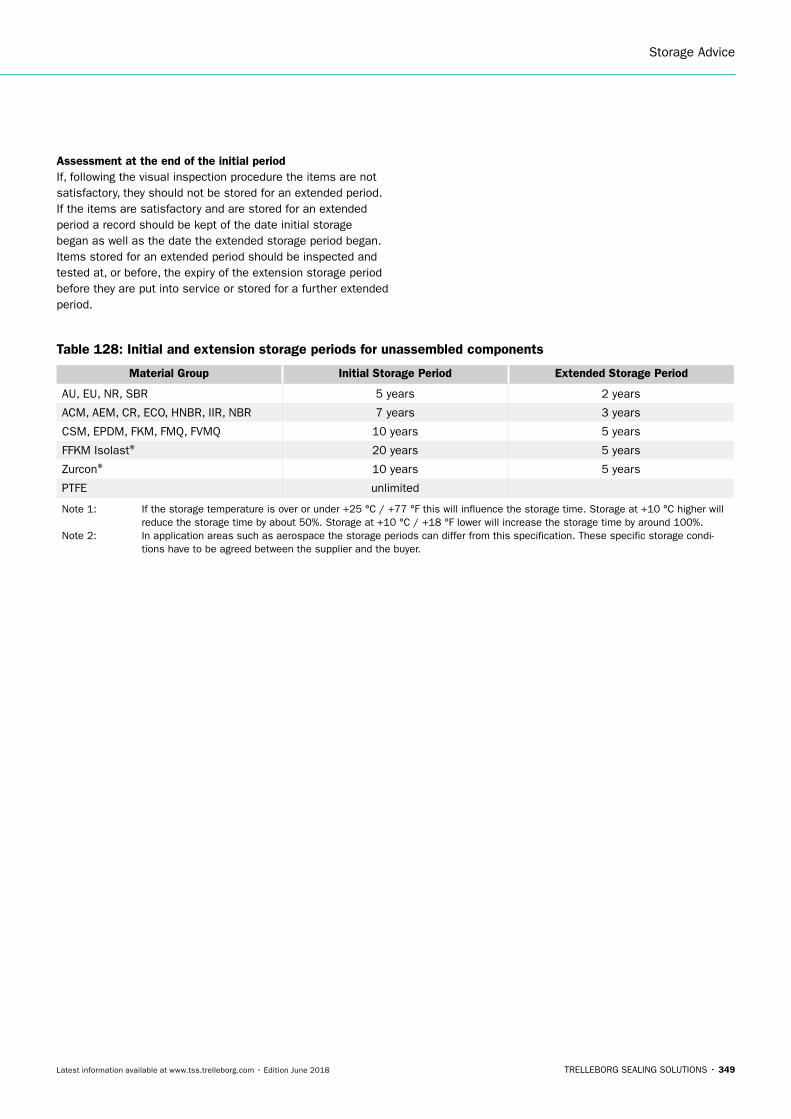
Storage Advice
TRELLEBORG SEALING SOLUTIONS • 349Latest information available at www.tss.trelleborg.com • Edition June 2018
Assessment at the end of the initial periodIf, following the visual inspection procedure the items are not satisfactory, they should not be stored for an extended period. If the items are satisfactory and are stored for an extended period a record should be kept of the date initial storage began as well as the date the extended storage period began. Items stored for an extended period should be inspected and tested at, or before, the expiry of the extension storage period before they are put into service or stored for a further extended period.
Table 128: Initial and extension storage periods for unassembled components
Material Group Initial Storage Period Extended Storage Period
AU, EU, NR, SBR 5 years 2 years
ACM, AEM, CR, ECO, HNBR, IIR, NBR 7 years 3 years
CSM, EPDM, FKM, FMQ, FVMQ 10 years 5 years
FFKM Isolast® 20 years 5 years
Zurcon® 10 years 5 years
PTFE unlimited
Note 1: If the storage temperature is over or under +25 °C / +77 °F this will influence the storage time. Storage at +10 °C higher will reduce the storage time by about 50%. Storage at +10 °C / +18 °F lower will increase the storage time by around 100%.
Note 2: In application areas such as aerospace the storage periods can differ from this specification. These specific storage condi-tions have to be agreed between the supplier and the buyer.
Trelleborg SeAlINg SolUTIoNS
yoUr pArTNer for SeAlINg TechNology
RotarySeals
facebook.com/TrelleborgSealingSolutions
twitter.com/TrelleborgSeals
youtube.com/TrelleborgSeals
linkedin.com/company/trelleborg-sealing-solutions
If you’d like to talk to Trelleborg Sealing Solutions, find your local contact at: www.tss.trelleborg.com/worldwide
Version no. 99
GB
TCATXE0
61
8
www.TSS.Trelleborg.com
Trelleborg is a world leader in engineered polymer solutions that seal, damp and protect critical applications in demanding environments. Its innovative solutions accelerate
performance for customers in a sustainable way.
Trelleborg Sealing Solutions is a leading developer, manufacturer and supplier of precision seals, bearings and custom-molded polymer components. It focuses on meeting the most demanding needs of aerospace, automotive and
general industrial customers with innovative solutions.
Copyright ©
20
18 Trelleborg A
B (publ). A
ll rights reserved. Information and related m
aterials are subject to change without notice.