Embed Size (px)
Citation preview
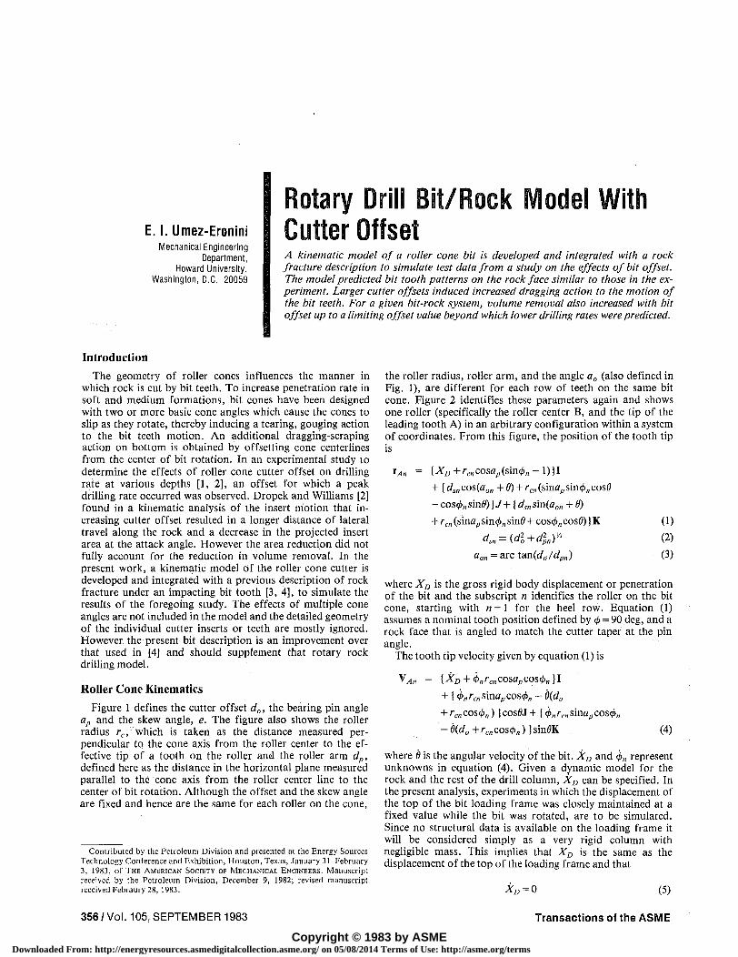
E. I. Umez-Eronini Mechanical Engineering
Department, Howard University,
Washington, D.C. 20059
Rotary Drill Bit/Rock Model With Cutter Offset A kinematic model of a roller cone bit is developed and integrated with a rock fracture description to simulate test data from a study on the effects of bit offset. The model predicted bit tooth patterns on the rock face similar to those in the experiment. Larger cutter offsets induced increased dragging action to the motion of the bit teeth. For a given bit-rock system, volume removal also increased with bit offset up to a limiting offset value beyond which lower drilling rates were predicted.
Introduction
The geometry of roller cones influences the manner in which rock is cut by bit teeth. To increase penetration rate in soft and medium formations, bit cones have been designed with two or more basic cone angles which cause the cones to slip as they rotate, thereby inducing a tearing, gouging action to the bit teeth motion. An additional dragging-scraping action on bottom is obtained by offsetting cone centerlines from the center of bit rotation. In an experimental study to determine the effects of roller cone cutter offset on drilling rate at various depths [1, 2], an offset for which a peak drilling rate occurred was observed. Dropek and Williams [2] found in a kinematic analysis of the insert motion that increasing cutter offset resulted in a longer distance of lateral travel along the rock and a decrease in the projected insert area at the attack angle. However the area reduction did not fully account for the reduction in volume removal. In the present work, a kinematic model of the roller cone cutter is developed and integrated with a previous description of rock fracture under an impacting bit tooth [3, 4], to simulate the results of the foregoing study. The effects of multiple cone angles are not included in the model and the detailed geometry of the individual cutter inserts or teeth are mostly ignored. However the present bit description is an improvement over that used in [4] and should supplement that rotary rock drilling model.
Roller Cone Kinematics
Figure 1 defines the cutter offset d0, the bearing pin angle ap and the skew angle, e. The figure also shows the roller radius rc, which is taken as the distance measured perpendicular to the cone axis from the roller center to the effective tip of a tooth on the roller and the roller arm dp, defined here as the distance in the horizontal plane measured parallel to the cone axis from the roller center line to the center of bit rotation. Although the offset and the skew angle are fixed and hence are the same for each roller on the cone,
Contributed by the Petroleum Division and presented at the Energy Sources Technology Conference and Exhibition, Houston, Texas, January 31-February 3, 1983, of THE AMERICAN SOCIETY OF MECHANICAL ENGINEERS. Manuscript
received by the Petroleum Division, December 9, 1982; revised manuscript received Febraury 28, 1983.
the roller radius, roller arm, and the angle a0 (also defined in Fig. 1), are different for each row of teeth on the same bit cone. Figure 2 identifies these parameters again and shows one roller (specifically the roller center B, and the tip of the leading tooth A) in an arbitrary configuration within a system of coordinates. From this figure, the position of the tooth tip is
IA„ = {XD+rcncosap(sin<l>„-l)}l
+ [ds„cos(aon +6) + rcn(smaps'm(j)ncos8
-cos(t>„sind))J+ [dsnsm(aon +0)
+ rm (sinap sin<£„ sin0 + cos$„ cos0)) K (1) dsn = (dl+dln)'
A (2) aon=avcta.n(d0/dpn) (3)
where XD is the gross rigid body displacement or penetration of the bit and the subscript n identifies the roller on the bit cone, starting with n=\ for the heel row. Equation (1) assumes a nominal tooth position defined by </> = 90 deg, and a rock face that is angled to match the cutter taper at the pin angle.
The tooth tip velocity given by equation (1) is
VA„ = {XD + j>„rc„cosapcos<j>n)l + {4>„rc„svt\apcos<j>„ - 0(do
+ rcncos<l>„) )cos0J + (</>„/-c„sinapcos</>„ - 6{d0 + rcn cos</>„)) sin0K (4)
where 0 is the angular velocity of the bit. XD and 4>„ represent unknowns in equation (4). Given a dynamic model for the rock and the rest of the drill column, XD can be specified. In the present analysis, experiments in which the displacement of the top of the bit loading frame was closely maintained at a fixed value while the bit was rotated, are to be simulated. Since no structural data is available on the loading frame it will be considered simply as a very rigid column with negligible mass. This implies that XD is the same as the displacement of the top of the loading frame and that
Xn = 0 (5)
356 / Vol. 105, SEPTEMBER 1983 Transactions of the ASME
Copyright © 1983 by ASMEDownloaded From: http://energyresources.asmedigitalcollection.asme.org/ on 05/08/2014 Terms of Use: http://asme.org/terms
OFFSET, d
Fig. 1 Cutter offset and pin angle definition
To determine 0„, the following conditions are imposed on equation (4):
Fig. 2 Coordinate system and instantaneous tooth forces
(a) the angular velocity of the cone is determined only by the heel roller;
(b) the leading tooth on the heel roller is free to slip in the horizontal plane only in the direction parallel to the cone axis.
These conditions imply
<j>n = </> for all n
and
(6)
Nomenclature
B„ ;#„,,
B0 = c, = cv = ET = En = E/c =
EfS =
1 an
Fdn -F = * sn
Hn =
I =
J =
K =
Ka \Kd =
p" :
R = "V An =
lateral travel distance of tooth tip; maximum Bn within tooth period minimum tooth contact length constant of fragment surface area constant of crater volume threshold energy energy input in normal tooth penetration fracture energy (per unit area) in compression fracture energy (per unit area and unit shear deformation) axial bit tooth force lateral drag tooth force lateral bit tooth force projected fracture length in normal penetration unit vector in X-coordinate direction (Fig. 2) unit vector in y-coordinate direction (Fig. 2) unit vector in Z-coordinate direction (Fig. 2) load-penetration slope, axial load; lateral drag force available rotary power at bit tooth projected chip surface length; maximum Q„ within tooth period heel circle radius, defined in Fig. 1 tooth tip velocity vector
Van = rate of penetration of tooth tip Vdn = tooth tip drag speed V0„ = crater volume X-D — rigid body displacement of entire bit
X„,max = maximum tooth penetration bearing pin angle effective tooth flat length cutter offset cone roller arm, defined in Fig. 1 cutter skew angle unit vector in x'-coordinate direction (Fig. 2) unit vector in .y'-coordinate direction (Fig. 2) unit vector in z' -coordinate direction (Fig. 2) roller cone row number, n = 1 for heel row tooth tip position vector roller radius, tooth tip to cone axis characteristic length in normal penetration effective tooth flat width penetration of trailing tooth tooth included angle exponent in stored elastic energy function angular displacement of bit energy use rate in normal penetration angular displacement of cone roller angle between row teeth
ap = b =
••pn
e
i =
k' =
s = w =
X/in =
7 9
A
<t>tn
Journal of Energy Resources Technology SEPTEMBER 1983, Vol. 105 / 357
Downloaded From: http://energyresources.asmedigitalcollection.asme.org/ on 05/08/2014 Terms of Use: http://asme.org/terms
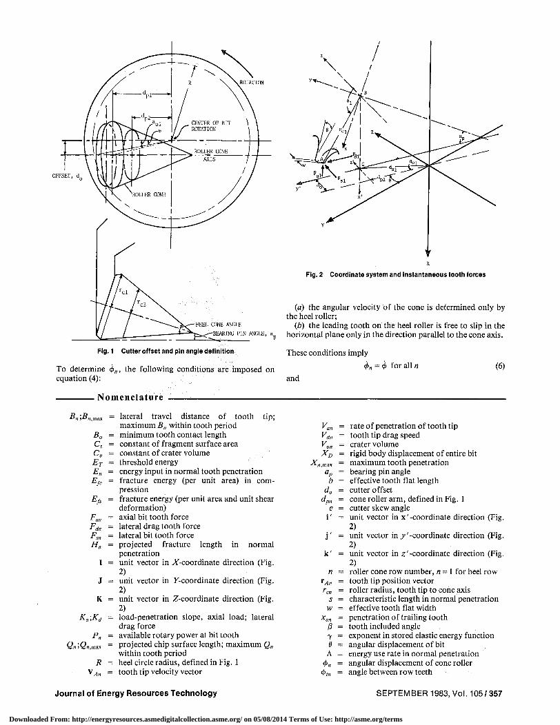
(a) (e)
.Fig. 3 Bit·tooth patterns from experiment at 68.947 MN/m2 mudpressure (2.54·mm penetration) after Oropek and Williams [1) - (a) offset= O. mm, (b) offset = 3.175 mm, (e) offset = 4.648 mm, (d) offset =6.096mm
(7). ( dp1 ).t/>= +sinap ()rei sint/> I
The second condition was motivated by observations on aplate sprocket physical model of the roller cone cutter.
In terms of the x'y'Z I coordinates, the leading tooth tipvelocity for the heel row is
VAl = ( ¢rcl cosapcost/>I l i' + {(¢sinap
- iJ)rcl COSt/>1 - do iJ Jj' + Ok' (8)
It is assumed that the trailing tooth becomes the leading toothwhen it penetrates the rock face. The condition for this eventis
power available at the tooth is given by
Pn=Fsn (rensinapsint/>n +dpn ) iJ- Fdn (rcncost/>n +do) iJ (10)
Since a detailed description of the loading frame has not beenmade, the thrust component of the total power will beignored1 and the rotary power will be considered the availablepower at the tooth. Assuming that the tooth action is made upof independent indentation and fragmentation sequences withthe fragmentation determined by the rotary power [4], theaxial force can be described separately from the lateral forces.Using the model developed in [3], the axial force is given by
xan = (XD +rencosap[sin(t/>n -t/>tn)-lll >0
where t/>tn is the angle between teeth on the roller.
Rock Model
(9)
(lla)
Figure 2 shows the forces acting on a leading tooth in thex'y'z' coordinate system. In terms of these forces, the rotary ~is quantity is usually negligible relative to the rotary power.
358/ Vol. 105, SEPTEMBER 1983 Transactions of the ASME
Downloaded From: http://energyresources.asmedigitalcollection.asme.org/ on 05/08/2014 Terms of Use: http://asme.org/terms
dt H =
Vm;En<ET
F V "" "" ;E„>Er
(116)
bE •fc
dt F V (lie)
Van = <t>rcn cosapcos<£„ (llcO
The lateral force Fs„ and the axial force Fa„ are assumed to be components of a reactive force in the x' — z' plane and are related by
Fsn=Fan/tan/3 (12)
The instantaneous chip fragmentation direction is considered the z' axis. Prior to threshold energy input, the potential chip surface length Q„, is proportional to the tooth penetration
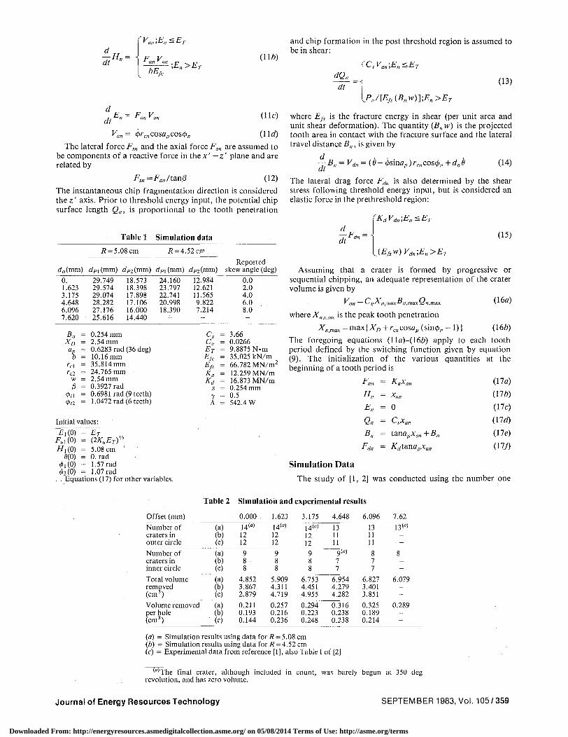
Table 1 Simulation data
rf0(mm) 0. 1.623 3.175 4.648 6.096 7.620
B0 = XD =
Op = b =
rc\ = rC2 =
w = (3 =
0(1 = 0(2 =
# = 5.08 cm
ofpi(mm) dp2(mm) 29.749 18.573 29.574 18.398 29.074 17.898 28.282 17.106 27.176 16.000 25.616 14.440
0.254 mm 2.54 mm 0.6283 rad (36 deg) 10.16mm 35.814mm 24.765 mm 2.54 mm 0.3927 rad 0.6981 rad (9 teeth) 1.0472 rad (6 teeth)
Initial values:
£,(0) = Fa ,(0) = i / , (0) =
8(0) = 0,(0) = 02(0) =
ET {2KaET)Vl
5.08 cm 0. rad 1.57 rad 1.07 rad
# = 4.52 cm
dpi (mm) 24.160 23.797 22.741 20.998 18.390
~
dn(mm) 12.984 12.621 11.565 9.822 7.214 -
Q cu ET E/c Efs Ka Kd
s y A
Reported skew angle (deg)
0.0 2.0 4.0 6.0 8.0 -
= 3.66 = 0.0266 = 9.8875 N.m = 35.025 kN/m = 66.782 MN/m2
= 12.259 MN/m = 16.873 MN/m = 0.254 mm = 0.5 = 542.4 W
and chip formation in the post threshold region is assumed to be in shear:
dQn
dt
CsVa„',E„ <ET
P„/[Efi{B„w)];E„>ET
(13)
where Ejs is the fracture energy in shear (per unit area and unit shear deformation). The quantity (B,,w) is the projected tooth area in contact with the fracture surface and the lateral travel distance B„, is given by
—B„ = Vd„ = (6- j>smap)rc„cos<£„ + d06 dt
(14)
The lateral drag force Fd„ is also determined by the shear stress following threshold energy input, but is considered an elastic force in the prethreshold region:
d
1tFd"~
KdVdn\En<ET
(Efsw)Vd„;E„>ET
(15)
Assuming that a crater is formed by progressive or sequential chipping, an adequate representation of the crater volume is given by
V on — ^ v-A- n ,max^*n, max Qnj (16a)
^«,max =max(ArD +rc„cosap (sin<£„ - 1)) (166)
The foregoing equations (lla)-(166) apply to each tooth period defined by the switching function given by equation (9). The initialization of the various quantities at the beginning of a tooth period is
F * an H„
En
Qn
Bn
Fdn
ft-a^an
~ Xatl
= 0
— i^sXan
= t<mapxan+B0
= Kdtanapxan
(17a)
(176)
(17c)
(lid)
(lie)
(17/)
Equations (17) for other variables.
Simulation Data
The study of [1, 2] was conducted using the number one
Table 2 Simulation and experimental results
Offset (mm)
Number of craters in outer circle
Number of craters in inner circle
Total volume removed (cm3)
Volume removed per hole (cm3)
(a) (b) (c)
(a) (b) (c)
(a) (b) (c)
(a) (b) (c)
0.000
14"" 12 12
9 8 8
4.852 3.867 2.879
0.211 0.193 0.144
1.623
14<a)
12 12
9 8 8
5.909 4.311 4.719
0.257 0.216 0.236
3.175
14"" 12 12 9 8 8
6.753 4.451 4.955
0.294 0.223 0.248
4.648
13 11 11
9(0)
7 7
6.954 4.279 4.282
0.316 0.238 0.238
6.096
13 11 11
8 7 7
6.827 3.401 3.851
0.325 0.189 0.214
7.62
13""
8
6.079
0.289
(a) = Simulation results using data for R - 5.08 cm (b) = Simulation results using data for R = 4.52 cm (c) = Experimental data from reference [1], also Table I of [2]
'"'The final crater, although included in count, was barely begun at 350 deg revolution, and has zero volume.
Journal of Energy Resources Technology SEPTEMBER 1983, Vol. 105/359
Downloaded From: http://energyresources.asmedigitalcollection.asme.org/ on 05/08/2014 Terms of Use: http://asme.org/terms
Offset = 3.175 mm
© • • •
KM: ^
©i^ p ;©-© •©•••
© • •
s: ©
..©i. • t . . - . - * - * - . - ^ - . . . . . . . . . • > . - ) - .
o -s.eao -4,088 -s.aee -2.000 -i.eee a. aea i.aea 2.090 3, aea 4.see s.eee
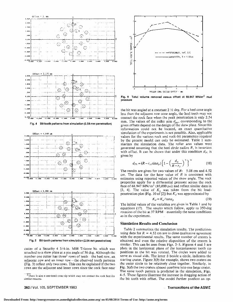
Fig. 4 Bit-tooth patterns from simulation (2.54-mm penetration)
Offset = 4.648 mm
i . eeo
• see
0.00a
- . 5 8 3
- i . s e e
-1 .S00
-2 .808
-2 .500
•©•! ©£<# ;©'¥ ©-0-
...0. ©' ©I .0.
•©- ...©...
; .e«9 - 4 .000 -3 .aea -z.t z.eae 3.1
2 . ( 3 8
2.000
1 . ( 8 *
1 .000
.109
0.000
- . 0 0 0
- 1 . 0 4 1
- 1 . 1 0 0
-2 .000
Offset * 6.096 mm
-2 .MB
•j©~ .©..i® r...@i
^B* • 0
•©;
...©..
-0-
©i:©l^.: ..©..
- i . a o * - 4 ,aae - s . e e a -2 .eae
Fig. 5 Bit-tooth patterns from simulation (2.54-mm penetration)
cutter of a Security 4 3/4-in. M88 Tricone bit which was attached to a skew plate at a pin angle of 36 deg. Although the number one cutter has three2 rows of teeth - the heel row, an adjacent row and an inner row- the observed tooth patterns (Fig. 3) reflect only two rows. This can be explained if the two rows are the adjacent and inner rows since the rock face near
There is also a one-tooth cone tip which may not contact the rock face for similar reasons.
—•EXPERIMENT, Ref. [ 1 ]
— SIMULATION, R = 4 . 5 2 a n
2 3 4
ROLLER CONE CUTTER OFFSET - mm
Fig. 6 Total volume removed versus offset at 68.947 MN/m mud pressure
the bit was angled at a constant 2 Vi deg. For a heel cone angle less than the adjacent row cone angle, the heel teeth may not contact the rock face when the peak penetration is only 2.54 mm. The values of the roller arm dp„, corresponding to the given offsets depend on the design of the skew plate. Since this information could not be located, an exact quantitative simulation of the experiments is not possible. Also, applicable values for the various rock and rock-bit parameters required by the present model can only be estimated. Table 1 summarizes the simulation data. The roller arm values were generated assuming that the heel circle radius R, is invariant with offset. It can be shown that under this condition dPX is given by
dn=(R-rclsmap)\\-(-^-) ] ' (18)
The results are given for two values of R: 5.08 cm and 4.52 cm. The data for the later value of R is consistent with estimates using reported values of the skew angle. The rock properties apply for a differential pressure across the rock face of 68.947 MN/m2 (10,000 psi) and reflect similar data in [3, 4]. The value of Ka was taken from the bit load-penetration plot (Fig. 10 of [2]) but Kd was approximated by
Kd=Ka/tanap (19)
The initial values of the variables are given in Table 1 and by equations (17). The results which follow, apply to 350-deg rotation of the bit at 37 RPM - essentially the same conditions as in the experiment.
Simulation Results and Conclusion
Table 2 summarizes the simulation results. The predictions using data for R = 4.52 cm are in close qualitative agreement with the experimental results. The same number of craters is obtained and even the relative disposition of the craters is similar. This can be seen from Figs. 3-5. Figures 4 and 5 are plots in the horizontal plane of the instantaneous tooth tip positions as the bit was rotated. The circles were added to serve as visual aids. The letter S beside a circle, indicates the starting crater. Figure 3(b) for example, shows two craters on the outer circle to be relatively close together. Similarly, in Fig. 3(d) the two craters almost combine into one large crater. The same tooth pattern is predicted in the simulation, Figs. 4-5. These figures illustrate the increase in dragging action of the bit teeth with offset. The model further predicts an op-
360/Vol. 105, SEPTEMBER 1983 Transactions of the ASME
Downloaded From: http://energyresources.asmedigitalcollection.asme.org/ on 05/08/2014 Terms of Use: http://asme.org/terms

timum cutter offset under the given conditions. This is shown in Fig. 6. The predicted optimum offset based on the total volume removed, is close to the experimental value but is higher when the basis is the volume removed per hole (Table 2). Such differences could be due in part to mismatch in the simulation data and the geometry of the real system. The present roller cone bit representation provides an adequate description of the essential effects of cutter offset observed in the study [1,2].
Acknowledgments
This material is based upon work supported by the National Science Foundation under Grant No. CME-
Proceedings of the Second International Offshore Mechanics and Artie Engineering Symposium, eds., J. S. Chung, V. J. Lunardini (see JERT Mar. 1983 issue for the List of Papers).
Partial topics covered: small computer and microprocessor control in simulation, hardware design, instrumentation and operation for the real offshore and arctic environment; TLP and guyed tower technology (theory and design); pipeline coating, submarine pipeline design and analysis, Northsea pipelaying, and full-scale pipeline burst test; pipeline-wave-soil interactions, buckling; cable dynamics; new-generation dynamic positioning; single-point mooring; recent OTEC design activities; ice mechanics, ice breaking, ice-structure interactions; permafrost; man-made arctic island design and much more.
1983 Bk. No. 100155 828 pp. $100.00 ASME Mem. $80.00
Proceedings of The First Offshore Mechanics/Article Engineering/Deepsea Systems Symposium, eds., J. S. Chung (see JERT Dec. 1982 issue for the List of Papers).
Vol. I Offshore Mechanics: Offshore Platforms; Hydrodynamics; Fatigue and Struc
ture Mechanics Ocean Margin Drilling: Deep Sea Drilling: Advanced Ocean Drilling Energy From the Ocean: Wave Energy: Thermal Energy
Vol. II Offshore Mechanics: Submarine Pipelines/Pipelaying; Marine Riser Design and
Cable System; Offshore Systems; Offshore Systems/Terminals Artie Engineering: Field Ice Mechanics; Ice Forces; Arctic Operations Engineer
ing; Permafrost Engineering
1982 Vol.1 Bk. No. 100147 246 pp. $45.00 ASME Mem. $22.50 1982 Vol.11 Bk. No. 100148 289 pp. $45.00 ASME Mem. $22.50
Pipeline Engineering Symposium, ed., K. Chickering (see JERT June 1983 issue for the List of Papers).
The technology presented in this volume on driling centers around the well bore. Papers cover the characteristics of special drilling fluids (i.e., foams) and measurement techniques for detecting gas or solids. Also presented are discussions of bit and tubular design and performance. Of special interest is material on turbodrilling, a technique used successfully in the USSR which may open new opportunities in the U.S.
1983 Bk. No. 100157 100 pp. $24.00 ASME Mem. $12.00
International Wind Energy Symposium, ed., A. N. Finlayson (see JERT June 1983 issue for the List of Papers).
The 30 articles in this volume are a result of the work of the recently formed Wind Enegy Subcommittee of ASME. It is hoped that these studies will increase the effective, efficient use of wind energy. This volume endeavors to assist the wind power energy industry by providing a forum for the open discussion of industry accomplishments and problems.
1982 Bk. No. 100153 349 pp. $60.00 ASME Mem. $48.00
8106443. The author would like to acknowledge the assistance of Mr. Jim Langford with data on the Tricone bit.
References
1 Dropek, R. K., and C. R. Williams, "A Study to Determine the Optimum Bit Offset at Various Drilling Depths," Report prepared by Terra Tek, Inc., for the U.S. Department of Energy, Oct. 1978.
2 Dropek, R. K., and C. R. Williams, "A Study to Determine Roller Cone Cutter Offset Effects at Various Drilling Depths," ASME Paper No. 78-Pet-23.
3 Eronini, I. E., "On Dynamic Fracture of Rock Under Bit Impact Loads," ASME JOURNAL OF ENERGY RESOURCES TECHNOLOGY, Vol. 104, 1982, pp.
105-107. 4 Eronini, I. E., et al., "A Dynamic Model for Rotary Rock Drilling,"
ASME JOURNAL OF ENERGY RESOURCES TECHNOLOGY, Vol. 104, 1982, pp.
108-120.
Industrial Pollution Control Symposium, ed., J. H. Chou (see JERT June 1983 issue for the List of Papers).
A wide range of insights is presented, in a study of pollution control in all aspects of energy production and use, by authorities from academia, industry and government. Papers range from law to technology, from acoustical ag-glomerators to electrostatic precipitators, from noise abatement to waste-heat recovery.
1983 Bk. No. 100156 Approx. 208 pp. $40.00 ASME Mem. $20.00
ANSI/ASEM B31.3—1980 Edition, Chemical Plant and Petroleum Refinery Piping (With Addenda up to the 1983 Edition)
Bk. No. AX3780 $75.00 ASME Mem. $60.00
Enhanced Recovery and Rotating Equipment: A Workbook For Petroleum Engineers, ed., K. B. Thayer
1980 Bk. No. 100135 79 pp. $25.00 ASME Mem. $12.50
OED Vol. 9 Ocean Engineering for OTEC, eds., O. M. Griffin, J. G. Giannotti
1980 Bk. No. 100129 87 pp. $14.00 ASME Mem. $7.00
Ocean Thermal Energy Conversion, ed., O. M. Griffin, 1978, Bk. No. G00139, 106 pp.
Deepwater Mooring and Drilling, ed., Y K. Lou, Bk. No. G00163, 1979, 212 pp.
Emerging Energy Technology, eds., W. B. Bradley, Z. L. Shuck, R. S., Sheridan, 1978, Bk. No. G00141, 128 pp.
Mining Technology for Energy Resources: Advances for the 80's, ed., A. H., Jones, Bk. No. G00140, 80 pp.
Please order by book number and tile and remit to:
ASME Order Department P.O. Box 3199 Grand Central Station New York, NY 10163
Other Publication of Interest:
Annual Review of U.S. Congress in Rock Mechanics: Rock Mass Characterization
For a free copy of this publication, write to:
U.S. National Committee for Rock Mechanics National Research Council 2101 Constitution Ave., NW Washington, DC 20418
Readers of the JOURNAL OF ENERGY RESOURCES TECHNOLOGY (JERT) Will be Interested in:
Journal of Energy Resources Technology SEPTEMBER 1983, Vol. 105/361
Downloaded From: http://energyresources.asmedigitalcollection.asme.org/ on 05/08/2014 Terms of Use: http://asme.org/terms