Embed Size (px)
Citation preview

Reference Manual00809-0100-4026, Rev JA
June 2015
Rosemount® 5400 SeriesSuperior Performance Two-Wire Non-Contacting Radar Level Transmitter

Reference Manual 00809-0100-4026, Rev JA
ContentsJune 2015
Contents
1Section 1: Introduction1.1 Manual overview . . . . . . . . . . . . . . . . . . . . . . . . . . . . . . . . . . . . . . . . . . . . . . . . . . . . . . . 1
1.2 Service support. . . . . . . . . . . . . . . . . . . . . . . . . . . . . . . . . . . . . . . . . . . . . . . . . . . . . . . . . 3
1.3 Product recycling/disposal . . . . . . . . . . . . . . . . . . . . . . . . . . . . . . . . . . . . . . . . . . . . . . . 4
1.4 Safety messages . . . . . . . . . . . . . . . . . . . . . . . . . . . . . . . . . . . . . . . . . . . . . . . . . . . . . . . . 4
2Section 2: Transmitter Overview2.1 Theory of operation . . . . . . . . . . . . . . . . . . . . . . . . . . . . . . . . . . . . . . . . . . . . . . . . . . . . . 7
2.2 Application examples . . . . . . . . . . . . . . . . . . . . . . . . . . . . . . . . . . . . . . . . . . . . . . . . . . . 8
2.3 System architecture. . . . . . . . . . . . . . . . . . . . . . . . . . . . . . . . . . . . . . . . . . . . . . . . . . . .10
2.4 Process characteristics . . . . . . . . . . . . . . . . . . . . . . . . . . . . . . . . . . . . . . . . . . . . . . . . .12
2.5 Components of the transmitter . . . . . . . . . . . . . . . . . . . . . . . . . . . . . . . . . . . . . . . . .14
2.6 Antenna selection guide/measuring range . . . . . . . . . . . . . . . . . . . . . . . . . . . . . . . .15
3Section 3: Mechanical Installation3.1 Safety messages . . . . . . . . . . . . . . . . . . . . . . . . . . . . . . . . . . . . . . . . . . . . . . . . . . . . . . .19
3.2 Installation procedure . . . . . . . . . . . . . . . . . . . . . . . . . . . . . . . . . . . . . . . . . . . . . . . . . .21
3.3 Mounting considerations . . . . . . . . . . . . . . . . . . . . . . . . . . . . . . . . . . . . . . . . . . . . . . .22
3.3.1 Mounting location . . . . . . . . . . . . . . . . . . . . . . . . . . . . . . . . . . . . . . . . . . . . . . .22
3.3.2 Special considerations in solids applications . . . . . . . . . . . . . . . . . . . . . . . . .24
3.3.3 Mounting in pipes . . . . . . . . . . . . . . . . . . . . . . . . . . . . . . . . . . . . . . . . . . . . . . . .25
3.3.4 Condensation conditions . . . . . . . . . . . . . . . . . . . . . . . . . . . . . . . . . . . . . . . . .26
3.3.5 Nozzle considerations . . . . . . . . . . . . . . . . . . . . . . . . . . . . . . . . . . . . . . . . . . . .27
3.3.6 Nozzle recommendations and requirements . . . . . . . . . . . . . . . . . . . . . . . .30
3.3.7 Service space . . . . . . . . . . . . . . . . . . . . . . . . . . . . . . . . . . . . . . . . . . . . . . . . . . . .32
3.3.8 Beam width . . . . . . . . . . . . . . . . . . . . . . . . . . . . . . . . . . . . . . . . . . . . . . . . . . . . .33
3.3.9 Vessel characteristics . . . . . . . . . . . . . . . . . . . . . . . . . . . . . . . . . . . . . . . . . . . . .35
3.3.10Disturbing objects . . . . . . . . . . . . . . . . . . . . . . . . . . . . . . . . . . . . . . . . . . . . . . .35
3.3.11Valves . . . . . . . . . . . . . . . . . . . . . . . . . . . . . . . . . . . . . . . . . . . . . . . . . . . . . . . . . .35
3.4 Mounting . . . . . . . . . . . . . . . . . . . . . . . . . . . . . . . . . . . . . . . . . . . . . . . . . . . . . . . . . . . . .36
3.4.1 Cone antenna flange connection. . . . . . . . . . . . . . . . . . . . . . . . . . . . . . . . . . .36
3.4.2 Process seal antenna . . . . . . . . . . . . . . . . . . . . . . . . . . . . . . . . . . . . . . . . . . . . .37
3.4.3 Rod antenna threaded connection . . . . . . . . . . . . . . . . . . . . . . . . . . . . . . . . .38
3.4.4 Rod antenna flanged connection. . . . . . . . . . . . . . . . . . . . . . . . . . . . . . . . . . .39
3.4.5 Tri Clamp tank connection . . . . . . . . . . . . . . . . . . . . . . . . . . . . . . . . . . . . . . . .40
iiiContents

Reference Manual00809-0100-4026, Rev JA
ContentsJune 2015
3.4.6 Bracket mounting on wall . . . . . . . . . . . . . . . . . . . . . . . . . . . . . . . . . . . . . . . . .41
3.4.7 Bracket mounting on pipe. . . . . . . . . . . . . . . . . . . . . . . . . . . . . . . . . . . . . . . . .42
4Section 4: Electrical Installation4.1 Safety messages . . . . . . . . . . . . . . . . . . . . . . . . . . . . . . . . . . . . . . . . . . . . . . . . . . . . . . .43
4.2 Wiring and power supply requirements. . . . . . . . . . . . . . . . . . . . . . . . . . . . . . . . . . .44
4.3 Cable/conduit entries . . . . . . . . . . . . . . . . . . . . . . . . . . . . . . . . . . . . . . . . . . . . . . . . . .45
4.3.1 Conduit electrical connector wiring (using minifast®) . . . . . . . . . . . . . . . .45
4.4 Grounding . . . . . . . . . . . . . . . . . . . . . . . . . . . . . . . . . . . . . . . . . . . . . . . . . . . . . . . . . . . .46
4.5 Cable selection . . . . . . . . . . . . . . . . . . . . . . . . . . . . . . . . . . . . . . . . . . . . . . . . . . . . . . . .46
4.6 Hazardous areas . . . . . . . . . . . . . . . . . . . . . . . . . . . . . . . . . . . . . . . . . . . . . . . . . . . . . . .47
4.7 External circuit breaker . . . . . . . . . . . . . . . . . . . . . . . . . . . . . . . . . . . . . . . . . . . . . . . . .47
4.7.1 Connecting the transmitter . . . . . . . . . . . . . . . . . . . . . . . . . . . . . . . . . . . . . . .47
4.8 HART. . . . . . . . . . . . . . . . . . . . . . . . . . . . . . . . . . . . . . . . . . . . . . . . . . . . . . . . . . . . . . . . .49
4.8.1 Power requirements. . . . . . . . . . . . . . . . . . . . . . . . . . . . . . . . . . . . . . . . . . . . . .49
4.8.2 Load limitations. . . . . . . . . . . . . . . . . . . . . . . . . . . . . . . . . . . . . . . . . . . . . . . . . .49
4.8.3 Non-intrinsically safe power supply. . . . . . . . . . . . . . . . . . . . . . . . . . . . . . . . .51
4.8.4 Intrinsically safe power supply . . . . . . . . . . . . . . . . . . . . . . . . . . . . . . . . . . . . .52
4.8.5 Type N approvals: non-sparking / energy-limited power supply . . . . . . . .53
4.8.6 Transient protection terminal block . . . . . . . . . . . . . . . . . . . . . . . . . . . . . . . .54
4.9 FOUNDATION fieldbus. . . . . . . . . . . . . . . . . . . . . . . . . . . . . . . . . . . . . . . . . . . . . . . . . . . .55
4.9.1 Power requirements. . . . . . . . . . . . . . . . . . . . . . . . . . . . . . . . . . . . . . . . . . . . . .55
4.9.2 Non-intrinsically safe power supply. . . . . . . . . . . . . . . . . . . . . . . . . . . . . . . . .57
4.9.3 Intrinsically safe power supply . . . . . . . . . . . . . . . . . . . . . . . . . . . . . . . . . . . . .58
4.9.4 Type N approvals: non-sparking / energy-limited power supply . . . . . . . .59
4.10HART to Modbus Converter (HMC) . . . . . . . . . . . . . . . . . . . . . . . . . . . . . . . . . . . . . .60
4.10.1Connecting the transmitter . . . . . . . . . . . . . . . . . . . . . . . . . . . . . . . . . . . . . . .60
4.10.2Connection terminals . . . . . . . . . . . . . . . . . . . . . . . . . . . . . . . . . . . . . . . . . . . .62
4.10.3RS-485 bus. . . . . . . . . . . . . . . . . . . . . . . . . . . . . . . . . . . . . . . . . . . . . . . . . . . . . .63
4.10.4Installation cases . . . . . . . . . . . . . . . . . . . . . . . . . . . . . . . . . . . . . . . . . . . . . . . .63
4.10.5External HART devices (slaves). . . . . . . . . . . . . . . . . . . . . . . . . . . . . . . . . . . . .65
4.11Establish HART communication . . . . . . . . . . . . . . . . . . . . . . . . . . . . . . . . . . . . . . . . .66
4.11.1Connect to the MA/MB terminals . . . . . . . . . . . . . . . . . . . . . . . . . . . . . . . . . .66
4.11.2Connect to the HART terminals . . . . . . . . . . . . . . . . . . . . . . . . . . . . . . . . . . . .68
4.12Optional devices . . . . . . . . . . . . . . . . . . . . . . . . . . . . . . . . . . . . . . . . . . . . . . . . . . . . . .69
4.12.1Tri-Loop™ HART to analog converter . . . . . . . . . . . . . . . . . . . . . . . . . . . . . . .69
4.12.2751 Field Signal Indicator . . . . . . . . . . . . . . . . . . . . . . . . . . . . . . . . . . . . . . . . .70
4.12.3Smart Wireless THUM™ Adapter . . . . . . . . . . . . . . . . . . . . . . . . . . . . . . . . . . .71
iv Contents
Reference Manual 00809-0100-4026, Rev JA
ContentsJune 2015
5Section 5: Basic Configuration/Start-up5.1 Safety messages . . . . . . . . . . . . . . . . . . . . . . . . . . . . . . . . . . . . . . . . . . . . . . . . . . . . . . .73
5.2 Overview . . . . . . . . . . . . . . . . . . . . . . . . . . . . . . . . . . . . . . . . . . . . . . . . . . . . . . . . . . . . .74
5.2.1 Basic configuration parameters . . . . . . . . . . . . . . . . . . . . . . . . . . . . . . . . . . . .74
5.2.2 Configuration tools . . . . . . . . . . . . . . . . . . . . . . . . . . . . . . . . . . . . . . . . . . . . . .74
5.3 Basic configuration parameters. . . . . . . . . . . . . . . . . . . . . . . . . . . . . . . . . . . . . . . . . .75
5.3.1 Measurement units . . . . . . . . . . . . . . . . . . . . . . . . . . . . . . . . . . . . . . . . . . . . . .75
5.3.2 Tank geometry . . . . . . . . . . . . . . . . . . . . . . . . . . . . . . . . . . . . . . . . . . . . . . . . . .75
5.3.3 Process conditions . . . . . . . . . . . . . . . . . . . . . . . . . . . . . . . . . . . . . . . . . . . . . . .77
5.3.4 Volume configuration . . . . . . . . . . . . . . . . . . . . . . . . . . . . . . . . . . . . . . . . . . . .78
5.3.5 Analog output (HART) . . . . . . . . . . . . . . . . . . . . . . . . . . . . . . . . . . . . . . . . . . . .81
5.3.6 Level and distance calibration . . . . . . . . . . . . . . . . . . . . . . . . . . . . . . . . . . . . .82
5.3.7 Echo tuning . . . . . . . . . . . . . . . . . . . . . . . . . . . . . . . . . . . . . . . . . . . . . . . . . . . . .83
5.3.8 ATC . . . . . . . . . . . . . . . . . . . . . . . . . . . . . . . . . . . . . . . . . . . . . . . . . . . . . . . . . . . .84
5.4 Basic configuration using RRM . . . . . . . . . . . . . . . . . . . . . . . . . . . . . . . . . . . . . . . . . .84
5.4.1 System requirements. . . . . . . . . . . . . . . . . . . . . . . . . . . . . . . . . . . . . . . . . . . . .84
5.4.2 Help in RRM . . . . . . . . . . . . . . . . . . . . . . . . . . . . . . . . . . . . . . . . . . . . . . . . . . . . .85
5.4.3 Installing the RRM software for HART communication . . . . . . . . . . . . . . . .85
5.4.4 Specifying the COM port . . . . . . . . . . . . . . . . . . . . . . . . . . . . . . . . . . . . . . . . . .87
5.4.5 To set the COM port buffers . . . . . . . . . . . . . . . . . . . . . . . . . . . . . . . . . . . . . . .88
5.4.6 Specifying measurement units. . . . . . . . . . . . . . . . . . . . . . . . . . . . . . . . . . . . .88
5.4.7 Installing the RRM software for FOUNDATION fieldbus . . . . . . . . . . . . . . . . . .88
5.4.8 Specifying measurement units. . . . . . . . . . . . . . . . . . . . . . . . . . . . . . . . . . . . .90
5.4.9 Using the Setup functions . . . . . . . . . . . . . . . . . . . . . . . . . . . . . . . . . . . . . . . . .91
5.4.10Guided setup . . . . . . . . . . . . . . . . . . . . . . . . . . . . . . . . . . . . . . . . . . . . . . . . . . . .92
5.4.11Using the Setup functions. . . . . . . . . . . . . . . . . . . . . . . . . . . . . . . . . . . . . . . 100
5.5 Configuration using a Field Communicator . . . . . . . . . . . . . . . . . . . . . . . . . . . . . 101
5.7 Basic configuration using AMS Suite. . . . . . . . . . . . . . . . . . . . . . . . . . . . . . . . . . . . 105
5.8 Configuration using DeltaV . . . . . . . . . . . . . . . . . . . . . . . . . . . . . . . . . . . . . . . . . . . 106
5.8.1 Advanced configuration . . . . . . . . . . . . . . . . . . . . . . . . . . . . . . . . . . . . . . . . 111
5.9 FOUNDATION fieldbus overview . . . . . . . . . . . . . . . . . . . . . . . . . . . . . . . . . . . . . . . . . 112
5.9.1 Assigning device tag and node address . . . . . . . . . . . . . . . . . . . . . . . . . . . 113
5.9.2 Foundation fieldbus block operation . . . . . . . . . . . . . . . . . . . . . . . . . . . . . 113
5.10Application examples . . . . . . . . . . . . . . . . . . . . . . . . . . . . . . . . . . . . . . . . . . . . . . . . 115
5.10.1Radar level transmitter - level value . . . . . . . . . . . . . . . . . . . . . . . . . . . . . . 115
5.10.2Radar level transmitter - level value in percent (%). . . . . . . . . . . . . . . . . . 116
5.11Tri-Loop™ HART to Analog Converter . . . . . . . . . . . . . . . . . . . . . . . . . . . . . . . . . . 117
5.12HART multidrop configuration . . . . . . . . . . . . . . . . . . . . . . . . . . . . . . . . . . . . . . . . 119
vContents
Reference Manual00809-0100-4026, Rev JA
ContentsJune 2015
6Section 6: Operation6.1 Safety messages . . . . . . . . . . . . . . . . . . . . . . . . . . . . . . . . . . . . . . . . . . . . . . . . . . . . . 121
6.2 Viewing measurement data . . . . . . . . . . . . . . . . . . . . . . . . . . . . . . . . . . . . . . . . . . . 122
6.2.1 Using the display panel . . . . . . . . . . . . . . . . . . . . . . . . . . . . . . . . . . . . . . . . . 122
6.2.2 Specifying display panel variables . . . . . . . . . . . . . . . . . . . . . . . . . . . . . . . . 122
6.2.3 Viewing measurement data in RRM . . . . . . . . . . . . . . . . . . . . . . . . . . . . . . 126
6.2.4 Viewing measurement data in AMS Suite and DeltaV . . . . . . . . . . . . . . . 127
6.3 LCD display error messages . . . . . . . . . . . . . . . . . . . . . . . . . . . . . . . . . . . . . . . . . . . 128
6.4 LED error messages . . . . . . . . . . . . . . . . . . . . . . . . . . . . . . . . . . . . . . . . . . . . . . . . . . 129
7Section 7: Service and Troubleshooting7.1 Safety messages . . . . . . . . . . . . . . . . . . . . . . . . . . . . . . . . . . . . . . . . . . . . . . . . . . . . . 131
7.2 Troubleshooting overview . . . . . . . . . . . . . . . . . . . . . . . . . . . . . . . . . . . . . . . . . . . . 133
7.3 Service overview. . . . . . . . . . . . . . . . . . . . . . . . . . . . . . . . . . . . . . . . . . . . . . . . . . . . . 134
7.3.1 Analyzing the measurement signal . . . . . . . . . . . . . . . . . . . . . . . . . . . . . . . 134
7.3.2 Surface pulse not found. . . . . . . . . . . . . . . . . . . . . . . . . . . . . . . . . . . . . . . . . 135
7.3.3 Registration of false echoes . . . . . . . . . . . . . . . . . . . . . . . . . . . . . . . . . . . . . 137
7.3.4 Using the Echo Curve Analyzer. . . . . . . . . . . . . . . . . . . . . . . . . . . . . . . . . . . 139
7.3.5 Using the Echo Curve Analyzer with a Field Communicator . . . . . . . . . . 142
7.4 Analog output calibration. . . . . . . . . . . . . . . . . . . . . . . . . . . . . . . . . . . . . . . . . . . . . 144
7.5 Logging measurement data. . . . . . . . . . . . . . . . . . . . . . . . . . . . . . . . . . . . . . . . . . . 145
7.6 Backing up the transmitter configuration . . . . . . . . . . . . . . . . . . . . . . . . . . . . . . . 146
7.7 Diagnostics . . . . . . . . . . . . . . . . . . . . . . . . . . . . . . . . . . . . . . . . . . . . . . . . . . . . . . . . . 147
7.8 Configuration report . . . . . . . . . . . . . . . . . . . . . . . . . . . . . . . . . . . . . . . . . . . . . . . . . 149
7.9 Viewing input and holding registers . . . . . . . . . . . . . . . . . . . . . . . . . . . . . . . . . . . . 150
7.10Reset to factory settings. . . . . . . . . . . . . . . . . . . . . . . . . . . . . . . . . . . . . . . . . . . . . . 151
7.11Surface search . . . . . . . . . . . . . . . . . . . . . . . . . . . . . . . . . . . . . . . . . . . . . . . . . . . . . . 152
7.12Using the Simulation Mode . . . . . . . . . . . . . . . . . . . . . . . . . . . . . . . . . . . . . . . . . . . 153
7.13Write protecting a transmitter . . . . . . . . . . . . . . . . . . . . . . . . . . . . . . . . . . . . . . . . 154
7.14Diagnostic messages . . . . . . . . . . . . . . . . . . . . . . . . . . . . . . . . . . . . . . . . . . . . . . . . 155
7.14.1Troubleshooting . . . . . . . . . . . . . . . . . . . . . . . . . . . . . . . . . . . . . . . . . . . . . . . 155
7.14.2Device status . . . . . . . . . . . . . . . . . . . . . . . . . . . . . . . . . . . . . . . . . . . . . . . . . . 155
7.14.3Errors. . . . . . . . . . . . . . . . . . . . . . . . . . . . . . . . . . . . . . . . . . . . . . . . . . . . . . . . . 156
7.14.4Warnings . . . . . . . . . . . . . . . . . . . . . . . . . . . . . . . . . . . . . . . . . . . . . . . . . . . . . 157
7.14.5Measurement status . . . . . . . . . . . . . . . . . . . . . . . . . . . . . . . . . . . . . . . . . . . 157
7.14.6Volume calculation status. . . . . . . . . . . . . . . . . . . . . . . . . . . . . . . . . . . . . . . 159
7.14.7Analog Output status. . . . . . . . . . . . . . . . . . . . . . . . . . . . . . . . . . . . . . . . . . . 160
7.14.8Application errors . . . . . . . . . . . . . . . . . . . . . . . . . . . . . . . . . . . . . . . . . . . . . . 161
vi Contents
Reference Manual 00809-0100-4026, Rev JA
ContentsJune 2015
7.15Troubleshooting . . . . . . . . . . . . . . . . . . . . . . . . . . . . . . . . . . . . . . . . . . . . . . . . . . . . 165
7.15.1Resource block . . . . . . . . . . . . . . . . . . . . . . . . . . . . . . . . . . . . . . . . . . . . . . . . 166
7.15.2Transducer block . . . . . . . . . . . . . . . . . . . . . . . . . . . . . . . . . . . . . . . . . . . . . . 167
7.15.3Analog Input (AI) function block . . . . . . . . . . . . . . . . . . . . . . . . . . . . . . . . . 167
8Section 8: Safety Instrumented Systems (4-20 mA Only)8.1 Safety messages . . . . . . . . . . . . . . . . . . . . . . . . . . . . . . . . . . . . . . . . . . . . . . . . . . . . . 169
8.2 Overview . . . . . . . . . . . . . . . . . . . . . . . . . . . . . . . . . . . . . . . . . . . . . . . . . . . . . . . . . . . 170
8.2.1 Applicable models . . . . . . . . . . . . . . . . . . . . . . . . . . . . . . . . . . . . . . . . . . . . . 170
8.2.2 Skill level of personnel . . . . . . . . . . . . . . . . . . . . . . . . . . . . . . . . . . . . . . . . . . 171
8.3 Functional specifications . . . . . . . . . . . . . . . . . . . . . . . . . . . . . . . . . . . . . . . . . . . . . 171
8.4 Installation. . . . . . . . . . . . . . . . . . . . . . . . . . . . . . . . . . . . . . . . . . . . . . . . . . . . . . . . . . 171
8.5 Configuration . . . . . . . . . . . . . . . . . . . . . . . . . . . . . . . . . . . . . . . . . . . . . . . . . . . . . . . 173
8.5.1 Damping. . . . . . . . . . . . . . . . . . . . . . . . . . . . . . . . . . . . . . . . . . . . . . . . . . . . . . 173
8.5.2 Alarm and saturation levels. . . . . . . . . . . . . . . . . . . . . . . . . . . . . . . . . . . . . . 173
8.5.3 Amplitude threshold . . . . . . . . . . . . . . . . . . . . . . . . . . . . . . . . . . . . . . . . . . . 174
8.5.4 Write protection . . . . . . . . . . . . . . . . . . . . . . . . . . . . . . . . . . . . . . . . . . . . . . . 174
8.5.5 Site acceptance . . . . . . . . . . . . . . . . . . . . . . . . . . . . . . . . . . . . . . . . . . . . . . . . 174
8.6 Operation and maintenance . . . . . . . . . . . . . . . . . . . . . . . . . . . . . . . . . . . . . . . . . . 174
8.6.1 General . . . . . . . . . . . . . . . . . . . . . . . . . . . . . . . . . . . . . . . . . . . . . . . . . . . . . . . 174
8.6.2 Inspection. . . . . . . . . . . . . . . . . . . . . . . . . . . . . . . . . . . . . . . . . . . . . . . . . . . . . 175
8.7 References. . . . . . . . . . . . . . . . . . . . . . . . . . . . . . . . . . . . . . . . . . . . . . . . . . . . . . . . . . 176
8.7.1 Specifications . . . . . . . . . . . . . . . . . . . . . . . . . . . . . . . . . . . . . . . . . . . . . . . . . 176
8.7.2 Failure rate data . . . . . . . . . . . . . . . . . . . . . . . . . . . . . . . . . . . . . . . . . . . . . . . 176
8.7.3 Useful lifetime . . . . . . . . . . . . . . . . . . . . . . . . . . . . . . . . . . . . . . . . . . . . . . . . . 176
8.8 Spare parts. . . . . . . . . . . . . . . . . . . . . . . . . . . . . . . . . . . . . . . . . . . . . . . . . . . . . . . . . . 176
8.9 Terms and definitions . . . . . . . . . . . . . . . . . . . . . . . . . . . . . . . . . . . . . . . . . . . . . . . . 176
AAppendix A: Reference DataA.1 Functional specifications . . . . . . . . . . . . . . . . . . . . . . . . . . . . . . . . . . . . . . . . . . . . . 179
A.1.1 General . . . . . . . . . . . . . . . . . . . . . . . . . . . . . . . . . . . . . . . . . . . . . . . . . . . . . . . 179
A.1.2 4-20 mA HART® (output option code H) . . . . . . . . . . . . . . . . . . . . . . . . . . 180
A.1.3 Foundation™ fieldbus (output option code F) . . . . . . . . . . . . . . . . . . . . . 183
A.1.4 Rosemount 2410 Tank Hub connectivity (output option code U) . . . . . . . . . . . . . . . . . . . . . . . . . . . . . . . . . . . . . . . . . 184
A.1.5 RS-485 with Modbus communication (output option code M) . . . . . . . . . . . . . . . . . . . . . . . . . . . . . . . . . . . . . . . . . 185
A.1.6 Display and configuration . . . . . . . . . . . . . . . . . . . . . . . . . . . . . . . . . . . . . . . 187
A.1.7 Diagnostics . . . . . . . . . . . . . . . . . . . . . . . . . . . . . . . . . . . . . . . . . . . . . . . . . . . 188
viiContents
Reference Manual00809-0100-4026, Rev JA
ContentsJune 2015
A.1.8 Temperature limits. . . . . . . . . . . . . . . . . . . . . . . . . . . . . . . . . . . . . . . . . . . . . 189
A.2 Performance specifications . . . . . . . . . . . . . . . . . . . . . . . . . . . . . . . . . . . . . . . . . . . 191
A.2.1 General . . . . . . . . . . . . . . . . . . . . . . . . . . . . . . . . . . . . . . . . . . . . . . . . . . . . . . . 191
A.2.2 Measuring range . . . . . . . . . . . . . . . . . . . . . . . . . . . . . . . . . . . . . . . . . . . . . . . 192
A.2.3 Environment . . . . . . . . . . . . . . . . . . . . . . . . . . . . . . . . . . . . . . . . . . . . . . . . . . 197
A.3 Physical specifications . . . . . . . . . . . . . . . . . . . . . . . . . . . . . . . . . . . . . . . . . . . . . . . . 198
A.3.1 Material selection . . . . . . . . . . . . . . . . . . . . . . . . . . . . . . . . . . . . . . . . . . . . . . 198
A.3.2 Housing and closure. . . . . . . . . . . . . . . . . . . . . . . . . . . . . . . . . . . . . . . . . . . . 198
A.3.3 Engineered solutions . . . . . . . . . . . . . . . . . . . . . . . . . . . . . . . . . . . . . . . . . . . 199
A.3.4 Tank connection and antennas . . . . . . . . . . . . . . . . . . . . . . . . . . . . . . . . . . 199
A.4 Dimensional drawings and mechanical properties . . . . . . . . . . . . . . . . . . . . . . . 202
A.4.1 Rosemount 5402 and 5401 with SST Cone Antenna (Model Code: 2S-8S). . . . . . . . . . . . . . . . . . . . . . . . . . . . . . . . . . . . . . . . . . . . 202
A.4.2 Rosemount 5402 and 5401 with Protective Plate Cone Antenna (Model Code: 2H-8H, 2M-8M, and 2N-8N) . . . . . . . . . . . . . . . . . . . . . . . . 203
A.4.3 Rosemount 5401 with Rod Antenna (Model Code: 1R-4R). . . . . . . . . . . 204
A.4.4 Rosemount 5402 with Process Seal Antenna (Model Code: 2P-4P) . . . . . . . . . . . . . . . . . . . . . . . . . . . . . . . . . . . . . . . . . . . 205
A.4.5 Bracket mounting (Model Code: BR). . . . . . . . . . . . . . . . . . . . . . . . . . . . . . 206
A.4.6 Process connections. . . . . . . . . . . . . . . . . . . . . . . . . . . . . . . . . . . . . . . . . . . . 207
A.5 Ordering information . . . . . . . . . . . . . . . . . . . . . . . . . . . . . . . . . . . . . . . . . . . . . . . . 208
BAppendix B: Product CertificationsB.1 Safety messages . . . . . . . . . . . . . . . . . . . . . . . . . . . . . . . . . . . . . . . . . . . . . . . . . . . . . 219
B.2 European Directive information . . . . . . . . . . . . . . . . . . . . . . . . . . . . . . . . . . . . . . . 221
B.3 FCC and ICC . . . . . . . . . . . . . . . . . . . . . . . . . . . . . . . . . . . . . . . . . . . . . . . . . . . . . . . . . 221
B.4 Safety Instrumented Systems (SIS) . . . . . . . . . . . . . . . . . . . . . . . . . . . . . . . . . . . . . 221
B.5 Hazardous locations certifications . . . . . . . . . . . . . . . . . . . . . . . . . . . . . . . . . . . . . 222
B.5.1 North-American certifications . . . . . . . . . . . . . . . . . . . . . . . . . . . . . . . . . . . 222
B.5.2 Canadian Standards Association (CSA) Approvals . . . . . . . . . . . . . . . . . . 223
B.5.3 European certifications . . . . . . . . . . . . . . . . . . . . . . . . . . . . . . . . . . . . . . . . . 224
B.5.4 IECEx Approval. . . . . . . . . . . . . . . . . . . . . . . . . . . . . . . . . . . . . . . . . . . . . . . . . 226
B.5.5 Technical Regulations Customs Union (EAC) certifications . . . . . . . . . . 228
B.5.6 Brazilian certifications . . . . . . . . . . . . . . . . . . . . . . . . . . . . . . . . . . . . . . . . . . 230
B.5.7 Chinese certifications. . . . . . . . . . . . . . . . . . . . . . . . . . . . . . . . . . . . . . . . . . . 231
B.5.8 Japanese certifications . . . . . . . . . . . . . . . . . . . . . . . . . . . . . . . . . . . . . . . . . . 232
B.5.9 Korean certifications . . . . . . . . . . . . . . . . . . . . . . . . . . . . . . . . . . . . . . . . . . . 233
B.5.10Other certifications . . . . . . . . . . . . . . . . . . . . . . . . . . . . . . . . . . . . . . . . . . . . 234
B.5.11Canadian Registration Number (CRN) . . . . . . . . . . . . . . . . . . . . . . . . . . . . 235
viii Contents
Reference Manual 00809-0100-4026, Rev JA
ContentsJune 2015
B.6 Approval drawings . . . . . . . . . . . . . . . . . . . . . . . . . . . . . . . . . . . . . . . . . . . . . . . . . . . 236
CAppendix C: Advanced ConfigurationC.1 Tank geometry . . . . . . . . . . . . . . . . . . . . . . . . . . . . . . . . . . . . . . . . . . . . . . . . . . . . . . 243
C.1.1 Distance offset (G) . . . . . . . . . . . . . . . . . . . . . . . . . . . . . . . . . . . . . . . . . . . . . 243
C.1.2 Minimum level offset (C) . . . . . . . . . . . . . . . . . . . . . . . . . . . . . . . . . . . . . . . . 244
C.1.3 Hold off distance. . . . . . . . . . . . . . . . . . . . . . . . . . . . . . . . . . . . . . . . . . . . . . . 244
C.1.4 Calibration distance . . . . . . . . . . . . . . . . . . . . . . . . . . . . . . . . . . . . . . . . . . . . 244
C.2 Advanced analog output settings . . . . . . . . . . . . . . . . . . . . . . . . . . . . . . . . . . . . . . 245
C.3 Advanced transmitter settings . . . . . . . . . . . . . . . . . . . . . . . . . . . . . . . . . . . . . . . . 245
C.3.1 Antenna type . . . . . . . . . . . . . . . . . . . . . . . . . . . . . . . . . . . . . . . . . . . . . . . . . . 245
C.3.2 Empty tank handling . . . . . . . . . . . . . . . . . . . . . . . . . . . . . . . . . . . . . . . . . . . 245
C.3.3 Full tank handling . . . . . . . . . . . . . . . . . . . . . . . . . . . . . . . . . . . . . . . . . . . . . . 247
C.3.4 Double bounce . . . . . . . . . . . . . . . . . . . . . . . . . . . . . . . . . . . . . . . . . . . . . . . . 247
C.3.5 Surface echo tracking . . . . . . . . . . . . . . . . . . . . . . . . . . . . . . . . . . . . . . . . . . 248
C.3.6 Filter settings . . . . . . . . . . . . . . . . . . . . . . . . . . . . . . . . . . . . . . . . . . . . . . . . . . 249
C.4 Advanced functions in RRM . . . . . . . . . . . . . . . . . . . . . . . . . . . . . . . . . . . . . . . . . . . 249
C.4.1 Empty tank handling . . . . . . . . . . . . . . . . . . . . . . . . . . . . . . . . . . . . . . . . . . . 249
C.4.2 Full tank handling . . . . . . . . . . . . . . . . . . . . . . . . . . . . . . . . . . . . . . . . . . . . . . 253
C.4.3 Double bounce . . . . . . . . . . . . . . . . . . . . . . . . . . . . . . . . . . . . . . . . . . . . . . . . 254
C.4.4 Surface echo tracking . . . . . . . . . . . . . . . . . . . . . . . . . . . . . . . . . . . . . . . . . . 255
C.4.5 Hold off setting . . . . . . . . . . . . . . . . . . . . . . . . . . . . . . . . . . . . . . . . . . . . . . . . 256
C.5 Signal Quality Metrics (SQM) . . . . . . . . . . . . . . . . . . . . . . . . . . . . . . . . . . . . . . . . . . 257
C.5.1 Available diagnostics measurements . . . . . . . . . . . . . . . . . . . . . . . . . . . . . 257
C.5.2 How to verify if Signal Quality Metrics is supported . . . . . . . . . . . . . . . . . 258
C.5.3 View Signal Quality Metrics values in RRM . . . . . . . . . . . . . . . . . . . . . . . . . 259
DAppendix D: Performing Proof TestD.1 Performing proof test . . . . . . . . . . . . . . . . . . . . . . . . . . . . . . . . . . . . . . . . . . . . . . . . 261
D.2 Field Communicator . . . . . . . . . . . . . . . . . . . . . . . . . . . . . . . . . . . . . . . . . . . . . . . . . 261
D.3 RRM. . . . . . . . . . . . . . . . . . . . . . . . . . . . . . . . . . . . . . . . . . . . . . . . . . . . . . . . . . . . . . . . 263
D.4 AMS Suite. . . . . . . . . . . . . . . . . . . . . . . . . . . . . . . . . . . . . . . . . . . . . . . . . . . . . . . . . . . 265
EAppendix E: Level Transducer BlockE.1 Overview . . . . . . . . . . . . . . . . . . . . . . . . . . . . . . . . . . . . . . . . . . . . . . . . . . . . . . . . . . . 267
E.1.1 Definition . . . . . . . . . . . . . . . . . . . . . . . . . . . . . . . . . . . . . . . . . . . . . . . . . . . . . 267
E.1.2 Channel definitions . . . . . . . . . . . . . . . . . . . . . . . . . . . . . . . . . . . . . . . . . . . . 267
E.2 Parameters and descriptions . . . . . . . . . . . . . . . . . . . . . . . . . . . . . . . . . . . . . . . . . . 268
ixContents
Reference Manual00809-0100-4026, Rev JA
ContentsJune 2015
E.3 Supported units . . . . . . . . . . . . . . . . . . . . . . . . . . . . . . . . . . . . . . . . . . . . . . . . . . . . . 273
E.3.1 Unit codes . . . . . . . . . . . . . . . . . . . . . . . . . . . . . . . . . . . . . . . . . . . . . . . . . . . . 273
E.4 Diagnostics device errors . . . . . . . . . . . . . . . . . . . . . . . . . . . . . . . . . . . . . . . . . . . . . 274
FAppendix F: Register Transducer BlockF.1 Overview . . . . . . . . . . . . . . . . . . . . . . . . . . . . . . . . . . . . . . . . . . . . . . . . . . . . . . . . . . . 275
F.1.1 Register access transducer block parameters . . . . . . . . . . . . . . . . . . . . . . 276
GAppendix G: Advanced Configuration Transducer BlockG.1 Overview . . . . . . . . . . . . . . . . . . . . . . . . . . . . . . . . . . . . . . . . . . . . . . . . . . . . . . . . . . . 279
G.1.1 Advanced configuration transducer block parameters . . . . . . . . . . . . . . 279
HAppendix H: Resource BlockH.1 Overview . . . . . . . . . . . . . . . . . . . . . . . . . . . . . . . . . . . . . . . . . . . . . . . . . . . . . . . . . . . 283
H.2 Parameters and descriptions . . . . . . . . . . . . . . . . . . . . . . . . . . . . . . . . . . . . . . . . . . 283
H.2.1 PlantWeb® alerts . . . . . . . . . . . . . . . . . . . . . . . . . . . . . . . . . . . . . . . . . . . . . . 288
H.2.2 Alarm priority. . . . . . . . . . . . . . . . . . . . . . . . . . . . . . . . . . . . . . . . . . . . . . . . . . 291
H.2.3 Recommended actions for PlantWeb alerts . . . . . . . . . . . . . . . . . . . . . . . 292
IAppendix I: Analog-Input BlockI.1 Simulation . . . . . . . . . . . . . . . . . . . . . . . . . . . . . . . . . . . . . . . . . . . . . . . . . . . . . . . . . . 298
I.2 Damping . . . . . . . . . . . . . . . . . . . . . . . . . . . . . . . . . . . . . . . . . . . . . . . . . . . . . . . . . . . 299
I.3 Signal conversion . . . . . . . . . . . . . . . . . . . . . . . . . . . . . . . . . . . . . . . . . . . . . . . . . . . . 299
I.4 Block errors . . . . . . . . . . . . . . . . . . . . . . . . . . . . . . . . . . . . . . . . . . . . . . . . . . . . . . . . . 300
I.5 Modes. . . . . . . . . . . . . . . . . . . . . . . . . . . . . . . . . . . . . . . . . . . . . . . . . . . . . . . . . . . . . . 300
I.6 Alarm detection . . . . . . . . . . . . . . . . . . . . . . . . . . . . . . . . . . . . . . . . . . . . . . . . . . . . . 301
I.6.1 Status handling . . . . . . . . . . . . . . . . . . . . . . . . . . . . . . . . . . . . . . . . . . . . . . . . 302
I.7 Configure the AI block. . . . . . . . . . . . . . . . . . . . . . . . . . . . . . . . . . . . . . . . . . . . . . . . 303
x Contents
xi
Reference Manual 00809-0100-4026, Rev JA June 2015
Rosemount 5400 Series
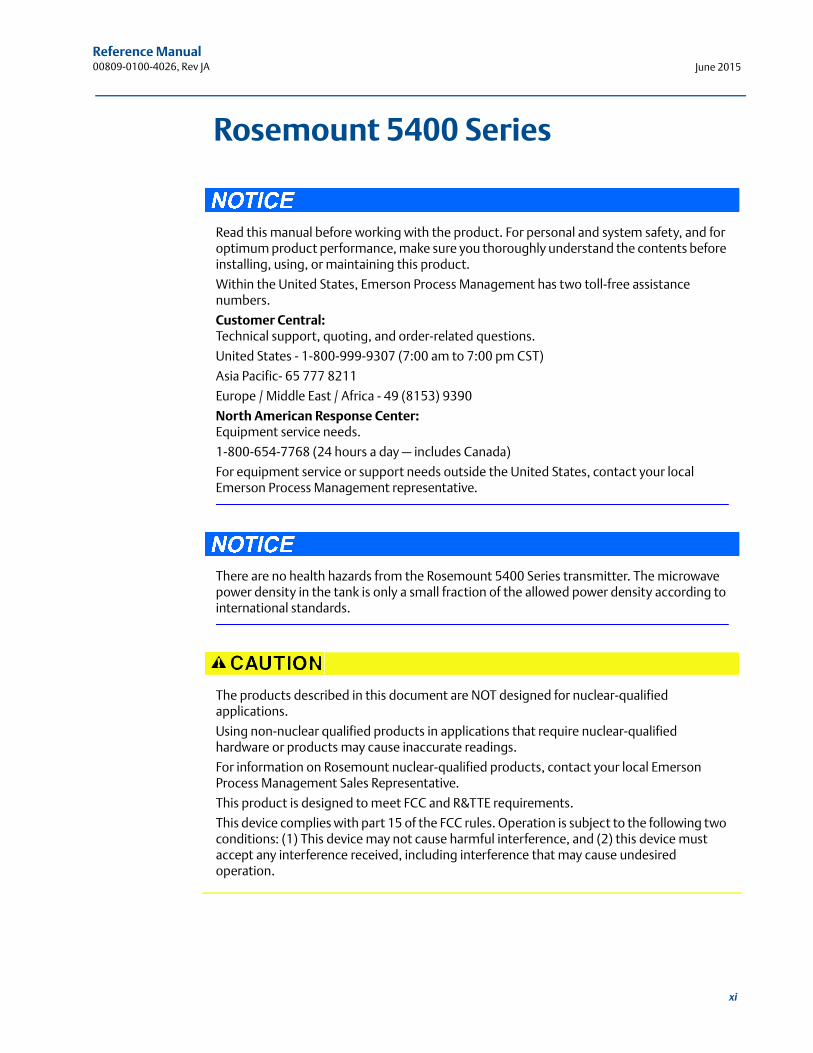
Read this manual before working with the product. For personal and system safety, and for optimum product performance, make sure you thoroughly understand the contents before installing, using, or maintaining this product.
Within the United States, Emerson Process Management has two toll-free assistance numbers.
Customer Central:Technical support, quoting, and order-related questions.
United States - 1-800-999-9307 (7:00 am to 7:00 pm CST)
Asia Pacific- 65 777 8211
Europe / Middle East / Africa - 49 (8153) 9390
North American Response Center:Equipment service needs.
1-800-654-7768 (24 hours a day — includes Canada)
For equipment service or support needs outside the United States, contact your local Emerson Process Management representative.
There are no health hazards from the Rosemount 5400 Series transmitter. The microwave power density in the tank is only a small fraction of the allowed power density according to international standards.
The products described in this document are NOT designed for nuclear-qualified applications.
Using non-nuclear qualified products in applications that require nuclear-qualified hardware or products may cause inaccurate readings.
For information on Rosemount nuclear-qualified products, contact your local Emerson Process Management Sales Representative.
This product is designed to meet FCC and R&TTE requirements.
This device complies with part 15 of the FCC rules. Operation is subject to the following two conditions: (1) This device may not cause harmful interference, and (2) this device must accept any interference received, including interference that may cause undesired operation.

xii
Reference Manual00809-0100-4026, Rev JAJune 2015
Reference Manual 00809-0100-4026, Rev JA
Section 1: IntroductionJune 2015
Section 1 Introduction
Manual overview . . . . . . . . . . . . . . . . . . . . . . . . . . . . . . . . . . . . . . . . . . . . . . . . . . . . . . . . . . . . page 1Service support . . . . . . . . . . . . . . . . . . . . . . . . . . . . . . . . . . . . . . . . . . . . . . . . . . . . . . . . . . . . . page 3Product recycling/disposal . . . . . . . . . . . . . . . . . . . . . . . . . . . . . . . . . . . . . . . . . . . . . . . . . . . page 4Safety messages . . . . . . . . . . . . . . . . . . . . . . . . . . . . . . . . . . . . . . . . . . . . . . . . . . . . . . . . . . . . page 4
1.1 Manual overview
The sections in this manual provide installation, configuration, and maintenance information for the Rosemount 5400 Series Radar Level Transmitter. The sections are organized as follows:
Section 2: Transmitter Overview
Theory of operation
Description of the transmitter
Process and vessel characteristics
Section 3: Mechanical Installation
Installation procedure
Mounting considerations
Mounting
Section 4: Electrical Installation
Cable/conduit entries
Grounding
Cable selection
Hazardous areas
External circuit breaker
Power requirements
Connecting the transmitter
Non-intrinsically safe power supply
Intrinsically safe power supply
Optional devices
1Introduction
Reference Manual00809-0100-4026, Rev JA
Section 1: IntroductionJune 2015
2 Introduction
Section 5: Basic Configuration/Start-up
Configuration instructions
Configuration using the Rosemount Radar Master (RRM) software
Configuration using a Field Communicator
Configuration using AMS® Suite
Configuration using DeltaV™
FOUNDATIONTM fieldbus overview
Section 6: Operation
Viewing measurement data with a display panel
Viewing measurement data in RRM
Viewing measurement data in AMS Suite and DeltaV
Section 7: Service and Troubleshooting
Troubleshooting
Error and warning codes
Communication errors
Section 8: Safety Instrumented Systems (4-20 mA Only)
Functional specifications
Installation
Configuration
Operation and maintenance
Spare parts
Appendix A: Reference Data
Specifications
Dimensional drawings and mechanical properties
Process connections
Ordering information
Appendix B: Product Certifications
European ATEX Directive information
FM approvals
CSA approvals
IECEx approvals
TIIS approval
NEPSI approvals
INMETRO approvals
Approval drawings
Reference Manual 00809-0100-4026, Rev JA
Section 1: IntroductionJune 2015
Appendix C: Advanced Configuration
Advanced tank geometry
Advanced transmitter settings
Advanced functions in RRM
Signal Quality Metrics (SQM)
Appendix D: Performing Proof Test
Describes the process of performing proof test
Appendix E: Level Transducer Block
Describes the operation and parameters of the Level Transducer Block
Appendix F: Register Transducer Block
Describes the operation and parameters of the Register Transducer Block
Appendix G: Advanced Configuration Transducer Block
Describes the operation and parameters of the Advanced Configurations Transducer Block
Appendix H: Resource Block
Describes the operation and parameters of the Resource Block
Appendix I: Analog-Input Block
Describes the operation and parameters of the Analog-Input function block
1.2 Service support
To expedite the return process outside of the United States, contact the nearest Emerson Process Management representative.
Within the United States, call the Emerson Process Management Instrument and Valves Response Center using the 1-800-654-RSMT (7768) toll-free number. This center, available 24 hours a day, will assist you with any needed information or materials.
The center will ask for product model and serial numbers, and will provide a Return Material Authorization (RMA) number. The center will also ask for the process material to which the product was last exposed.
Individuals who handle products exposed to a hazardous substance can avoid injury if they are informed of and understand the hazard. If the product being returned was exposed to a hazardous substance as defined by Occupational Safety and Health Administration (OSHA), a copy of the required Material Safety Data Sheet (MSDS) for each hazardous substance identified must be included with the returned goods.
3Introduction
Reference Manual00809-0100-4026, Rev JA
Section 1: IntroductionJune 2015
4 Introduction
Emerson Process Management Instrument and Valves Response Center representatives will explain the additional information and procedures necessary to return goods exposed to hazardous substances.
1.3 Product recycling/disposal
Recycling of equipment and packaging should be taken into consideration and disposed of in accordance with local and national legislation/regulations.
1.4 Safety messages
Procedures and instructions in this manual may require special precautions to ensure the safety of the personnel performing the operations. Information that raises potential safety issues is indicated by a warning symbol ( ). Refer to the safety messages listed at the beginning of each section before performing an operation preceded by this symbol.
Reference Manual 00809-0100-4026, Rev JA
Section 1: IntroductionJune 2015
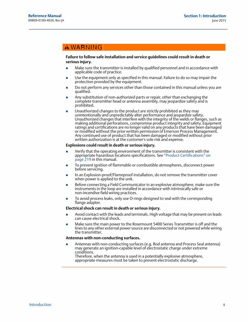
Failure to follow safe installation and service guidelines could result in death or serious injury.
Make sure the transmitter is installed by qualified personnel and in accordance with applicable code of practice.
Use the equipment only as specified in this manual. Failure to do so may impair the protection provided by the equipment.
Do not perform any services other than those contained in this manual unless you are qualified.
Any substitution of non-authorized parts or repair, other than exchanging the complete transmitter head or antenna assembly, may jeopardize safety and is prohibited.
Unauthorized changes to the product are strictly prohibited as they may unintentionally and unpredictably alter performance and jeopardize safety. Unauthorized changes that interfere with the integrity of the welds or flanges, such as making additional perforations, compromise product integrity and safety. Equipment ratings and certifications are no longer valid on any products that have been damaged or modified without the prior written permission of Emerson Process Management. Any continued use of product that has been damaged or modified without prior written authorization is at the customer's sole risk and expense.
Explosions could result in death or serious injury.
Verify that the operating environment of the transmitter is consistent with the appropriate hazardous locations specifications. See “Product Certifications” on page 219 in this manual.
To prevent ignition of flammable or combustible atmospheres, disconnect power before servicing.
In an Explosion-proof/Flameproof installation, do not remove the transmitter cover when power is applied to the unit.
Before connecting a Field Communicator in an explosive atmosphere, make sure the instruments in the loop are installed in accordance with intrinsically safe or non-incendive field wiring practices.
To avoid process leaks, only use O-rings designed to seal with the corresponding flange adapter.
Electrical shock can result in death or serious injury.
Avoid contact with the leads and terminals. High voltage that may be present on leads can cause electrical shock.
Make sure the main power to the Rosemount 5400 Series Transmitter is off and the lines to any other external power source are disconnected or not powered while wiring the transmitter.
Antennas with non-conducting surfaces.
Antennas with non-conducting surfaces (e.g. Rod antenna and Process Seal antenna) may generate an ignition-capable level of electrostatic charge under extreme conditions.Therefore, when the antenna is used in a potentially explosive atmosphere, appropriate measures must be taken to prevent electrostatic discharge.
5Introduction

Reference Manual00809-0100-4026, Rev JA
Section 1: IntroductionJune 2015
6 Introduction
Reference Manual 00809-0100-4026, Rev JA
Section 2: Transmitter OverviewJune 2015
Section 2 Transmitter Overview
Theory of operation . . . . . . . . . . . . . . . . . . . . . . . . . . . . . . . . . . . . . . . . . . . . . . . . . . . . . . . . . page 7Application examples . . . . . . . . . . . . . . . . . . . . . . . . . . . . . . . . . . . . . . . . . . . . . . . . . . . . . . . . page 8System architecture . . . . . . . . . . . . . . . . . . . . . . . . . . . . . . . . . . . . . . . . . . . . . . . . . . . . . . . . . page 10Process characteristics . . . . . . . . . . . . . . . . . . . . . . . . . . . . . . . . . . . . . . . . . . . . . . . . . . . . . . . page 12Components of the transmitter . . . . . . . . . . . . . . . . . . . . . . . . . . . . . . . . . . . . . . . . . . . . . . . page 14Antenna selection guide/measuring range . . . . . . . . . . . . . . . . . . . . . . . . . . . . . . . . . . . . . page 15
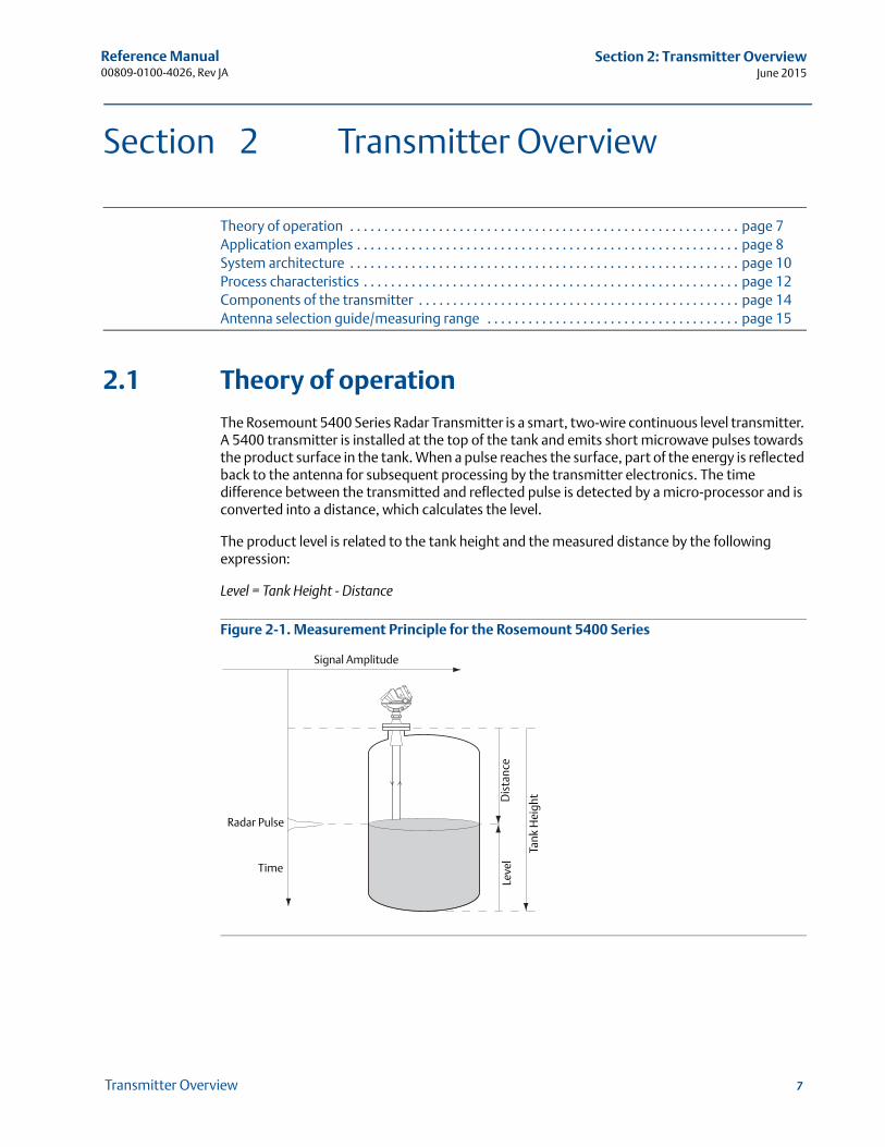
2.1 Theory of operation
The Rosemount 5400 Series Radar Transmitter is a smart, two-wire continuous level transmitter. A 5400 transmitter is installed at the top of the tank and emits short microwave pulses towards the product surface in the tank. When a pulse reaches the surface, part of the energy is reflected back to the antenna for subsequent processing by the transmitter electronics. The time difference between the transmitted and reflected pulse is detected by a micro-processor and is converted into a distance, which calculates the level.
The product level is related to the tank height and the measured distance by the following expression:
Level = Tank Height - Distance
Figure 2-1. Measurement Principle for the Rosemount 5400 Series
Time
Leve
lD
ista
nce
Tank
Hei
ght
Signal Amplitude
Radar Pulse
7Transmitter Overview
Reference Manual00809-0100-4026, Rev JA
Section 2: Transmitter OverviewJune 2015
8 Transmitter Overview
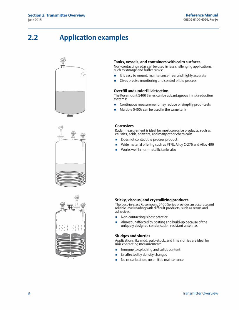
2.2 Application examples
Tanks, vessels, and containers with calm surfacesNon-contacting radar can be used in less challenging applications, such as storage and buffer tanks:
It is easy to mount, maintenance-free, and highly accurate Gives precise monitoring and control of the process
Overfill and underfill detectionThe Rosemount 5400 Series can be advantageous in risk reduction systems:
Continuous measurement may reduce or simplify proof-tests Multiple 5400s can be used in the same tank
CorrosivesRadar measurement is ideal for most corrosive products, such as caustics, acids, solvents, and many other chemicals:
Does not contact the process product Wide material offering such as PTFE, Alloy C-276 and Alloy 400 Works well in non-metallic tanks also
Sticky, viscous, and crystallizing productsThe best-in-class Rosemount 5400 Series provides an accurate and reliable level reading with difficult products, such as resins and adhesives:
Non-contacting is best practice Almost unaffected by coating and build-up because of the
uniquely designed condensation resistant antennas
Sludges and slurriesApplications like mud, pulp-stock, and lime slurries are ideal for non-contacting measurement:
Immune to splashing and solids content Unaffected by density changes No re-calibration, no or little maintenance
Reference Manual 00809-0100-4026, Rev JA
Section 2: Transmitter OverviewJune 2015
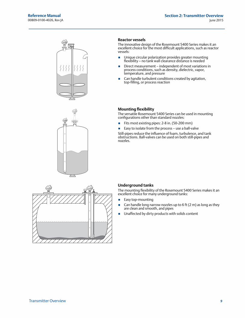
Reactor vesselsThe innovative design of the Rosemount 5400 Series makes it an excellent choice for the most difficult applications, such as reactor vessels:
Unique circular polarization provides greater mounting flexibility – no tank wall clearance distance is needed
Direct measurement – independent of most variations in process conditions, such as density, dielectric, vapor, temperature, and pressure
Can handle turbulent conditions created by agitation, top-filling, or process reaction
Mounting flexibilityThe versatile Rosemount 5400 Series can be used in mounting configurations other than standard nozzles:
Fits most existing pipes: 2-8 in. (50-200 mm) Easy to isolate from the process – use a ball-valveStill-pipes reduce the influence of foam, turbulence, and tank obstructions. Ball-valves can be used on both still-pipes and nozzles.
Underground tanksThe mounting flexibility of the Rosemount 5400 Series makes it an excellent choice for many underground tanks:
Easy top-mounting Can handle long narrow nozzles up to 6 ft (2 m) as long as they
are clean and smooth, and pipes Unaffected by dirty products with solids content
9Transmitter Overview
Reference Manual00809-0100-4026, Rev JA
Section 2: Transmitter OverviewJune 2015
10 Transmitter Overview
2.3 System architecture
The Rosemount 5400 Series Radar Transmitter is loop-powered, and uses the same two wires for power supply and output signal. The output is a 4-20 mA analog signal superimposed with a digital HART®, FOUNDATION™ fieldbus or Modbus® signal.
By using the optional HART Tri-Loop™, the HART signal can be converted up to three additional 4-20 mA analog signals.
With the HART protocol, multidrop configuration is possible. In this case, communication is restricted to digital, since current is fixed to the 4 mA minimum value.
The transmitter can be connected to a Rosemount 751 Field Signal Indicator, or it can be equipped with an integral display.
The transmitter can easily be configured using a Field Communicator or a PC with the Rosemount Radar Master (RRM) software. Rosemount 5400 Series transmitters can also be configured with the AMS® Suite and DeltaV™ software, and other tools that support Electronic Device Description Language (EDDL) functionality.
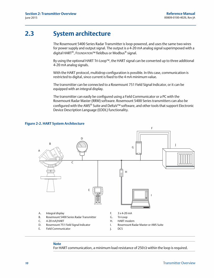
Figure 2-2. HART System Architecture
NoteFor HART communication, a minimum load resistance of 250 within the loop is required.
A
B
D
E
G
F
J
H
I
A. Integral displayB. Rosemount 5400 Series Radar TransmitterC. 4-20 mA/HARTD. Rosemount 751 Field Signal IndicatorE. Field Communicator
F. 3 x 4-20 mAG. Tri-LoopH. HART modemI. Rosemount Radar Master or AMS SuiteJ. DCS
C
Reference Manual 00809-0100-4026, Rev JA
Section 2: Transmitter OverviewJune 2015
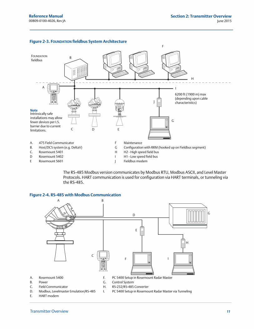
Figure 2-3. FOUNDATION fieldbus System Architecture
The RS-485 Modbus version communicates by Modbus RTU, Modbus ASCII, and Level Master Protocols. HART communication is used for configuration via HART terminals, or tunneling via the RS-485.
Figure 2-4. RS-485 with Modbus Communication
FOUNDATION fieldbus
NoteIntrinsically safe installations may allow fewer devices per I.S. barrier due to current limitations.
B
F
A
C D E
J
I
6200 ft (1900 m) max (depending upon cable characteristics)
G
H
A. 475 Field CommunicatorB. Host/DCS system (e.g. DeltaV)C. Rosemount 5401D Rosemount 5402E Rosemount 5601
F MaintenanceG Configuration with RRM (hooked up on Fieldbus segment)H H2 - High speed field busI H1 - Low speed field busJ Fieldbus modem
A
E
B
D G
H
F IC
A. Rosemount 5400B. PowerC. Field CommunicatorD. Modbus, Levelmaster Emulation/RS-485E. HART modem
F. PC 5400 Setup in Rosemount Radar MasterG. Control SystemH. RS-232/RS-485 ConverterI. PC 5400 Setup in Rosemount Radar Master via Tunneling
11Transmitter Overview
Reference Manual00809-0100-4026, Rev JA
Section 2: Transmitter OverviewJune 2015
12 Transmitter Overview
2.4 Process characteristics
Dielectric constant
A key parameter for measurement performance is reflectivity. A high dielectric constant of the media provides better reflection and enables a longer measuring range.
Foam
Rosemount 5400 Series Radar Transmitter measurement in foamy applications depends on the foam properties; light and airy or dense and heavy, high or low dielectrics, etc. If the foam is conductive and creamy, the transmitter may measure the surface of the foam. If the foam is less conductive, the microwaves may penetrate the foam and measure the liquid surface.
Turbulence
A calm surface gives better reflection than a turbulent surface. For turbulent applications, the maximum range of the radar transmitters is reduced. The range depends on the frequency, the antenna size, the dielectric of the material, and the degree of turbulence. Consult Tables 2-2 and 2-3 on page 16 for the expected maximum range with the variables listed.
Temperature/pressure/density and vapor
Temperature, pressure, product density, and vapor generally have no impact on measurements.
Condensation
For applications where heavy condensation and vapors may occur, the low frequency version Rosemount 5401 is recommended.
Tank characteristics
The conditions inside the tank have a significant impact on measurement performance. For more information see “Vessel characteristics” on page 35.
Solid surface
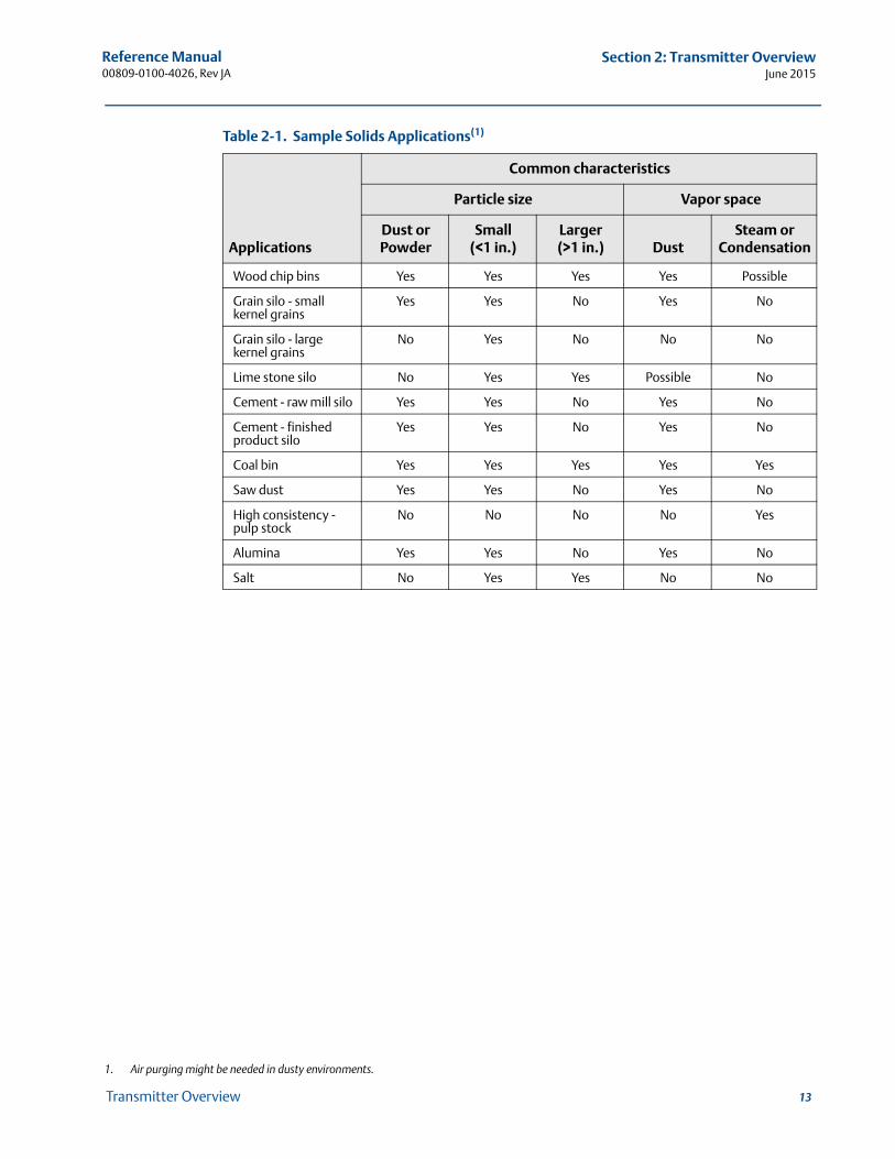
The surface of solid materials is rarely flat or horizontal. The angle of repose, or surface inclination, will change as the vessel fills and empties. There is often a lot of dust during the fill cycle. The dielectric value of many solids is fairly low. See Table 2-1 on page 2-13 for common solids characteristics.
For solids applications, the high frequency version Rosemount 5402 with 4 inch cone antenna is available.
Reference Manual 00809-0100-4026, Rev JA
Section 2: Transmitter OverviewJune 2015
Table 2-1. Sample Solids Applications(1)
Applications
Common characteristics
Particle size Vapor space
Dust or Powder
Small (<1 in.)
Larger (>1 in.) Dust
Steam or Condensation
Wood chip bins Yes Yes Yes Yes Possible
Grain silo - small kernel grains
Yes Yes No Yes No
Grain silo - large kernel grains
No Yes No No No
Lime stone silo No Yes Yes Possible No
Cement - raw mill silo Yes Yes No Yes No
Cement - finished product silo
Yes Yes No Yes No
Coal bin Yes Yes Yes Yes Yes
Saw dust Yes Yes No Yes No
High consistency - pulp stock
No No No No Yes
Alumina Yes Yes No Yes No
Salt No Yes Yes No No
1. Air purging might be needed in dusty environments.
13Transmitter Overview
Reference Manual00809-0100-4026, Rev JA
Section 2: Transmitter OverviewJune 2015
14 Transmitter Overview
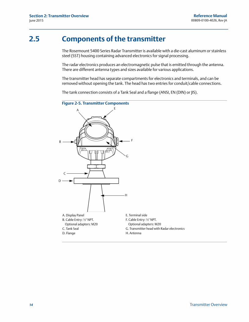
2.5 Components of the transmitter
The Rosemount 5400 Series Radar Transmitter is available with a die-cast aluminum or stainless steel (SST) housing containing advanced electronics for signal processing.
The radar electronics produces an electromagnetic pulse that is emitted through the antenna. There are different antenna types and sizes available for various applications.
The transmitter head has separate compartments for electronics and terminals, and can be removed without opening the tank. The head has two entries for conduit/cable connections.
The tank connection consists of a Tank Seal and a flange (ANSI, EN (DIN) or JIS).
Figure 2-5. Transmitter Components
B
G
H
A E
F
D
C
A. Display PanelB. Cable Entry: ½" NPT.
Optional adapters: M20C. Tank SealD. Flange
E. Terminal sideF. Cable Entry: ½" NPT.
Optional adapters: M20G. Transmitter head with Radar electronicsH. Antenna
Reference Manual 00809-0100-4026, Rev JA
Section 2: Transmitter OverviewJune 2015
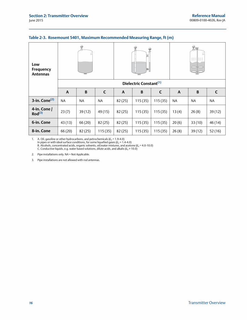
2.6 Antenna selection guide/measuring range
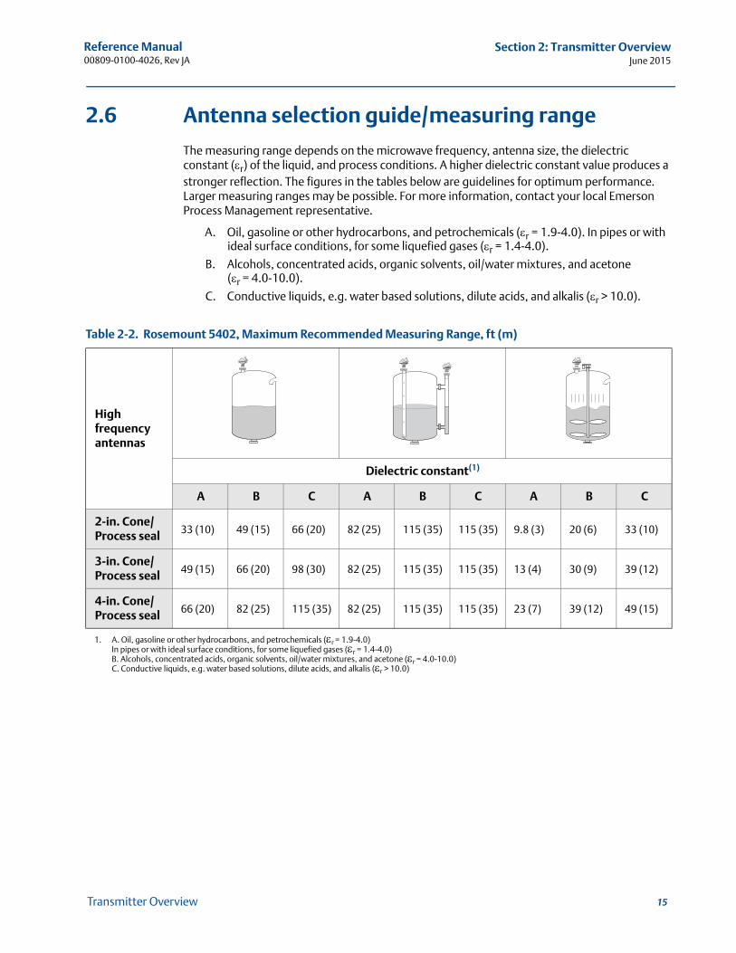
The measuring range depends on the microwave frequency, antenna size, the dielectric constant (r) of the liquid, and process conditions. A higher dielectric constant value produces a stronger reflection. The figures in the tables below are guidelines for optimum performance. Larger measuring ranges may be possible. For more information, contact your local Emerson Process Management representative.
A. Oil, gasoline or other hydrocarbons, and petrochemicals (r = 1.9-4.0). In pipes or with ideal surface conditions, for some liquefied gases (r = 1.4-4.0).
B. Alcohols, concentrated acids, organic solvents, oil/water mixtures, and acetone (r = 4.0-10.0).
C. Conductive liquids, e.g. water based solutions, dilute acids, and alkalis (r > 10.0).
Table 2-2. Rosemount 5402, Maximum Recommended Measuring Range, ft (m)
High frequency antennas
Dielectric constant(1)
1. A. Oil, gasoline or other hydrocarbons, and petrochemicals (r = 1.9-4.0)In pipes or with ideal surface conditions, for some liquefied gases (r = 1.4-4.0)B. Alcohols, concentrated acids, organic solvents, oil/water mixtures, and acetone (r = 4.0-10.0)C. Conductive liquids, e.g. water based solutions, dilute acids, and alkalis (r > 10.0)
A B C A B C A B C
2-in. Cone/Process seal 33 (10) 49 (15) 66 (20) 82 (25) 115 (35) 115 (35) 9.8 (3) 20 (6) 33 (10)
3-in. Cone/Process seal 49 (15) 66 (20) 98 (30) 82 (25) 115 (35) 115 (35) 13 (4) 30 (9) 39 (12)
4-in. Cone/Process seal 66 (20) 82 (25) 115 (35) 82 (25) 115 (35) 115 (35) 23 (7) 39 (12) 49 (15)
15Transmitter Overview
Reference Manual00809-0100-4026, Rev JA
Section 2: Transmitter OverviewJune 2015
16 Transmitter Overview
Table 2-3. Rosemount 5401, Maximum Recommended Measuring Range, ft (m)
Low Frequency Antennas
Dielectric Constant(1)
1. A. Oil, gasoline or other hydrocarbons, and petrochemicals (r = 1.9-4.0)In pipes or with ideal surface conditions, for some liquefied gases (r = 1.4-4.0)B. Alcohols, concentrated acids, organic solvents, oil/water mixtures, and acetone (r = 4.0-10.0)C. Conductive liquids, e.g. water based solutions, dilute acids, and alkalis (r > 10.0)
A B C A B C A B C
3-in. Cone(2)
2. Pipe installations only. NA = Not Applicable.
NA NA NA 82 (25) 115 (35) 115 (35) NA NA NA
4-in. Cone / Rod(3)
3. Pipe installations are not allowed with rod antennas.
23 (7) 39 (12) 49 (15) 82 (25) 115 (35) 115 (35) 13 (4) 26 (8) 39 (12)
6-in. Cone 43 (13) 66 (20) 82 (25) 82 (25) 115 (35) 115 (35) 20 (6) 33 (10) 46 (14)
8-in. Cone 66 (20) 82 (25) 115 (35) 82 (25) 115 (35) 115 (35) 26 (8) 39 (12) 52 (16)
Reference Manual 00809-0100-4026, Rev JA
Section 2: Transmitter OverviewJune 2015
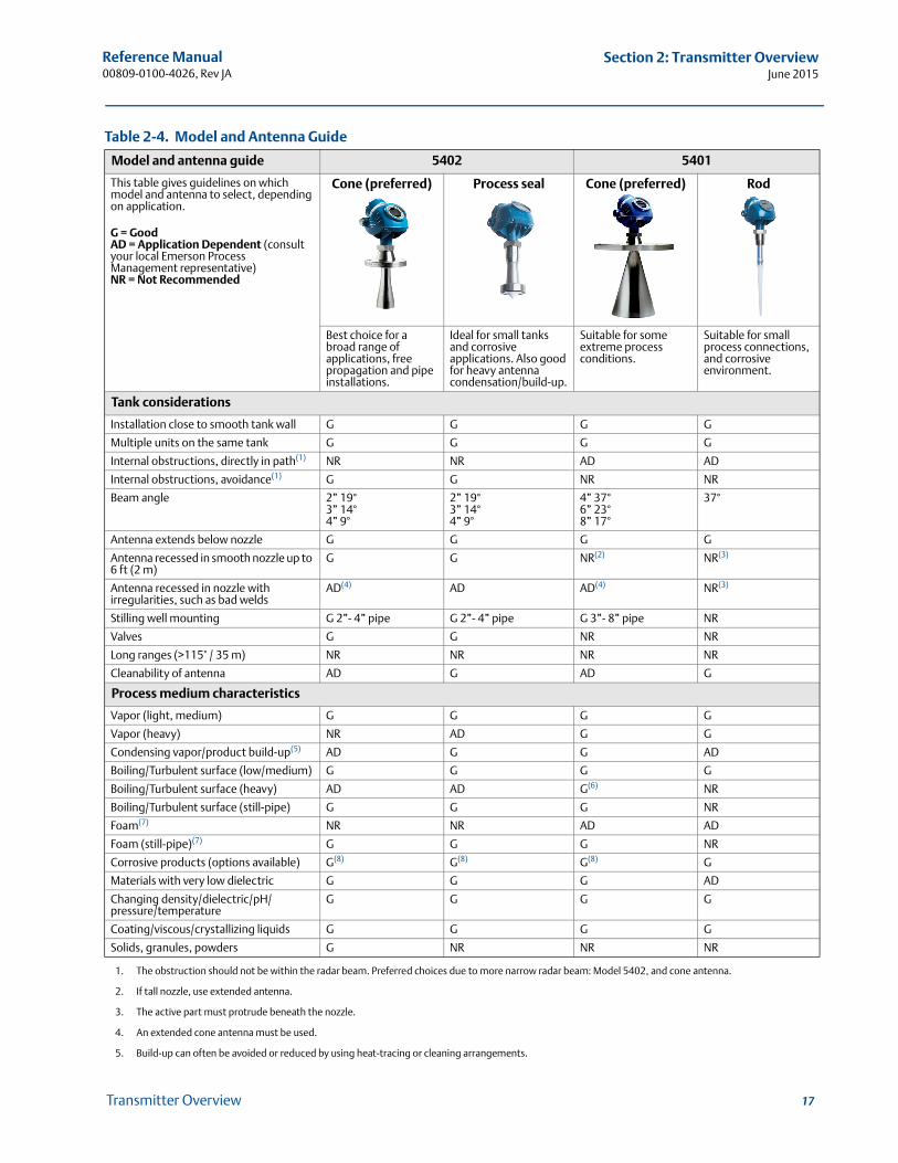
Table 2-4. Model and Antenna Guide
Model and antenna guide 5402 5401
This table gives guidelines on which model and antenna to select, depending on application.
G = GoodAD = Application Dependent (consult your local Emerson Process Management representative)NR = Not Recommended
Cone (preferred) Process seal Cone (preferred) Rod
Best choice for a broad range of applications, free propagation and pipe installations.
Ideal for small tanks and corrosive applications. Also good for heavy antenna condensation/build-up.
Suitable for some extreme process conditions.
Suitable for small process connections, and corrosive environment.
Tank considerations
Installation close to smooth tank wall G G G G
Multiple units on the same tank G G G G
Internal obstructions, directly in path(1) NR NR AD AD
Internal obstructions, avoidance(1)
1. The obstruction should not be within the radar beam. Preferred choices due to more narrow radar beam: Model 5402, and cone antenna.
G G NR NR
Beam angle 2” 19°3” 14°4” 9°
2” 19°3” 14°4” 9°
4” 37°6” 23°8” 17°
37°
Antenna extends below nozzle G G G G
Antenna recessed in smooth nozzle up to 6 ft (2 m)
G G NR(2)
2. If tall nozzle, use extended antenna.
NR(3)
3. The active part must protrude beneath the nozzle.
Antenna recessed in nozzle with irregularities, such as bad welds
AD(4)
4. An extended cone antenna must be used.
AD AD(4) NR(3)
Stilling well mounting G 2”- 4” pipe G 2”- 4” pipe G 3”- 8” pipe NR
Valves G G NR NR
Long ranges (>115’ / 35 m) NR NR NR NR
Cleanability of antenna AD G AD G
Process medium characteristics
Vapor (light, medium) G G G G
Vapor (heavy) NR AD G G
Condensing vapor/product build-up(5)
5. Build-up can often be avoided or reduced by using heat-tracing or cleaning arrangements.
AD G G AD
Boiling/Turbulent surface (low/medium) G G G G
Boiling/Turbulent surface (heavy) AD AD G(6) NR
Boiling/Turbulent surface (still-pipe) G G G NR
Foam(7) NR NR AD AD
Foam (still-pipe)(7) G G G NR
Corrosive products (options available) G(8) G(8) G(8) G
Materials with very low dielectric G G G AD
Changing density/dielectric/pH/ pressure/temperature
G G G G
Coating/viscous/crystallizing liquids G G G G
Solids, granules, powders G NR NR NR
17Transmitter Overview

Reference Manual00809-0100-4026, Rev JA
Section 2: Transmitter OverviewJune 2015
18 Transmitter Overview
6. Use a 6 or 8 in. (150-200 mm) cone antenna.
7. Foam can either reflect, be invisible, or absorb the radar signal. Pipe mounting is advantageous since it reduces the foaming tendency.
8. Other wetted material options include Alloy C-276 and Alloy 400. See the Rosemount 5400 Series Product Data Sheet (Document No. 00813-0100-4026) for details.

Reference Manual 00809-0100-4026, Rev JA
Section 3: Mechanical InstallationJune 2015
Section 3 Mechanical Installation
Safety messages . . . . . . . . . . . . . . . . . . . . . . . . . . . . . . . . . . . . . . . . . . . . . . . . . . . . . . . . . . . . page 19Installation procedure . . . . . . . . . . . . . . . . . . . . . . . . . . . . . . . . . . . . . . . . . . . . . . . . . . . . . . . page 21Mounting considerations . . . . . . . . . . . . . . . . . . . . . . . . . . . . . . . . . . . . . . . . . . . . . . . . . . . . page 22Mounting . . . . . . . . . . . . . . . . . . . . . . . . . . . . . . . . . . . . . . . . . . . . . . . . . . . . . . . . . . . . . . . . . . page 36
3.1 Safety messages
Procedures and instructions in this section may require special precautions to ensure the safety of the personnel performing the operations. Information that raises potential safety issues is indicated by a warning symbol ( ). Refer to the following safety messages before performing an operation preceded by this symbol.
19Mechanical Installation

Reference Manual00809-0100-4026, Rev JA
Section 3: Mechanical InstallationJune 2015
Failure to follow safe installation and service guidelines could result in death or serious injury.
Make sure only qualified personnel perform installation or service. Use the equipment only as specified in this manual. Failure to do so may impair the
protection provided by the equipment. Any substitution of non-recognized spare parts may jeopardize safety. Repair, e.g.
substitution of components etc. may also jeopardize safety and is under no circumstances allowed.
Process leaks could result in death or serious injury.
Make sure that the transmitter is handled carefully. If the Process Seal is damaged, gas might escape from the tank if the transmitter head is removed from the antenna.
Explosions could result in death or serious injury.
Verify that the operating environment of the transmitter is consistent with the appropriate hazardous locations specifications.
In an Explosion-proof/Flameproof installation, do not remove the transmitter cover when power is applied to the unit.
Before connecting a Field Communicator in an explosive atmosphere, make sure the instruments in the loop are installed in accordance with intrinsically safe or non-incendive field wiring practices.
Electrical shock can result in death or serious injury.
Avoid contact with the leads and terminals. High voltage that may be present on leads can cause electrical shock.
Make sure the main power to the Rosemount 5400 Series Transmitter is off and the lines to any other external power source are disconnected or not powered while wiring the transmitter.
Antennas with non-conducting surfaces.
Antennas with non-conducting surfaces (e.g. Rod antenna and Process Seal antenna) may generate an ignition-capable level of electrostatic charge under extreme conditions.Therefore, when the antenna is used in a potentially explosive atmosphere, appropriate measures must be taken to prevent electrostatic discharge.
20 Mechanical Installation
Reference Manual 00809-0100-4026, Rev JA
Section 3: Mechanical InstallationJune 2015
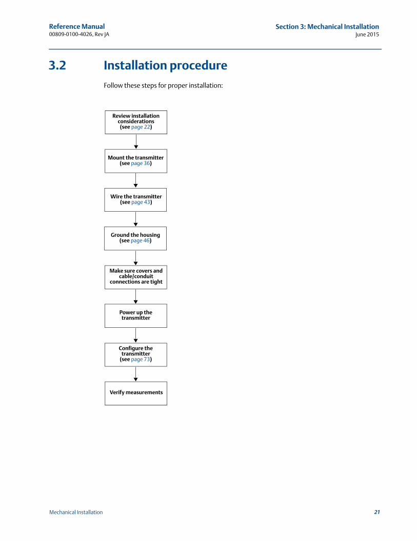
3.2 Installation procedure
Follow these steps for proper installation:
Review installation considerations(see page 22)
Mount the transmitter(see page 36)
Wire the transmitter(see page 43)
Make sure covers and cable/conduit
connections are tight
Power up the transmitter
Configure the transmitter
(see page 73)
Verify measurements
Ground the housing (see page 46)
21Mechanical Installation
Reference Manual00809-0100-4026, Rev JA
Section 3: Mechanical InstallationJune 2015
3.3 Mounting considerations
Before installing a Rosemount 5400 Series Transmitter, consider specific mounting requirements, vessel, and process characteristics.
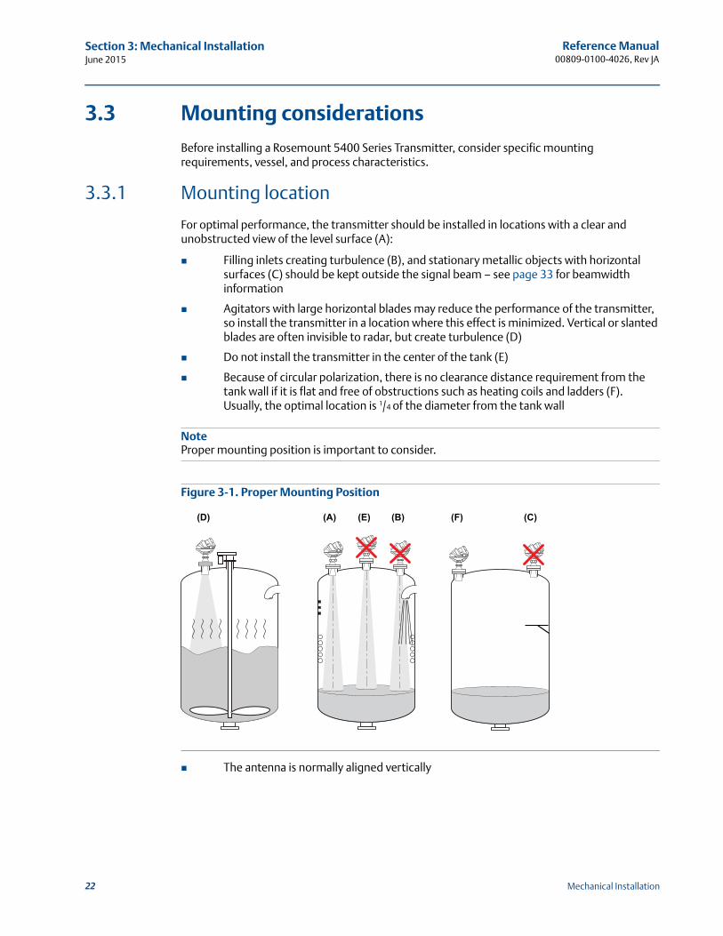
3.3.1 Mounting location
For optimal performance, the transmitter should be installed in locations with a clear and unobstructed view of the level surface (A):
Filling inlets creating turbulence (B), and stationary metallic objects with horizontal surfaces (C) should be kept outside the signal beam – see page 33 for beamwidth information
Agitators with large horizontal blades may reduce the performance of the transmitter, so install the transmitter in a location where this effect is minimized. Vertical or slanted blades are often invisible to radar, but create turbulence (D)
Do not install the transmitter in the center of the tank (E)
Because of circular polarization, there is no clearance distance requirement from the tank wall if it is flat and free of obstructions such as heating coils and ladders (F). Usually, the optimal location is 1/4 of the diameter from the tank wall
NoteProper mounting position is important to consider.
Figure 3-1. Proper Mounting Position
The antenna is normally aligned vertically
(D) (A) (E) (B) (F) (C)
22 Mechanical Installation
Reference Manual 00809-0100-4026, Rev JA
Section 3: Mechanical InstallationJune 2015
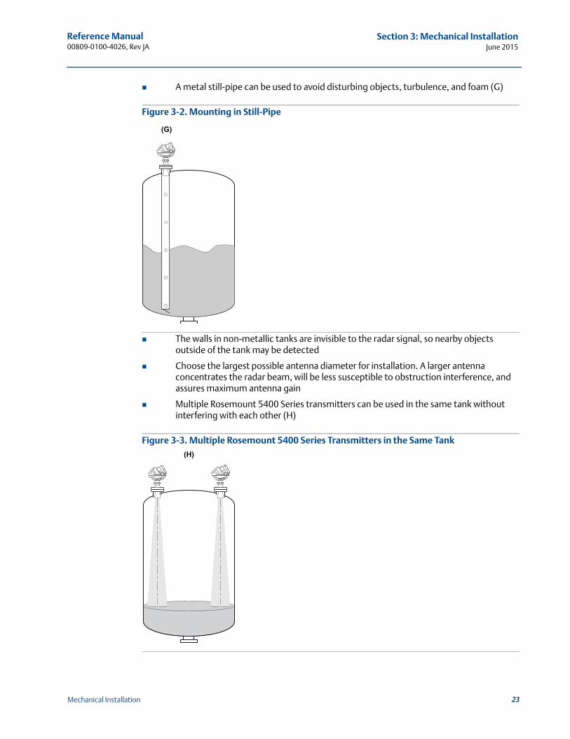
A metal still-pipe can be used to avoid disturbing objects, turbulence, and foam (G)
Figure 3-2. Mounting in Still-Pipe
The walls in non-metallic tanks are invisible to the radar signal, so nearby objects outside of the tank may be detected
Choose the largest possible antenna diameter for installation. A larger antenna concentrates the radar beam, will be less susceptible to obstruction interference, and assures maximum antenna gain
Multiple Rosemount 5400 Series transmitters can be used in the same tank without interfering with each other (H)
Figure 3-3. Multiple Rosemount 5400 Series Transmitters in the Same Tank
(G)
(H)
23Mechanical Installation
Reference Manual00809-0100-4026, Rev JA
Section 3: Mechanical InstallationJune 2015
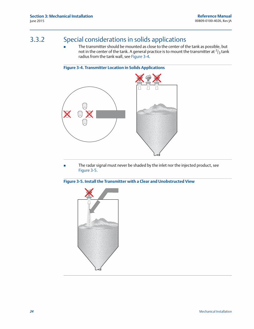
3.3.2 Special considerations in solids applications The transmitter should be mounted as close to the center of the tank as possible, but
not in the center of the tank. A general practice is to mount the transmitter at 2/3 tank radius from the tank wall, see Figure 3-4.
Figure 3-4. Transmitter Location in Solids Applications
The radar signal must never be shaded by the inlet nor the injected product, see Figure 3-5.
Figure 3-5. Install the Transmitter with a Clear and Unobstructed View
24 Mechanical Installation
Reference Manual 00809-0100-4026, Rev JA
Section 3: Mechanical InstallationJune 2015
3.3.3 Mounting in pipes
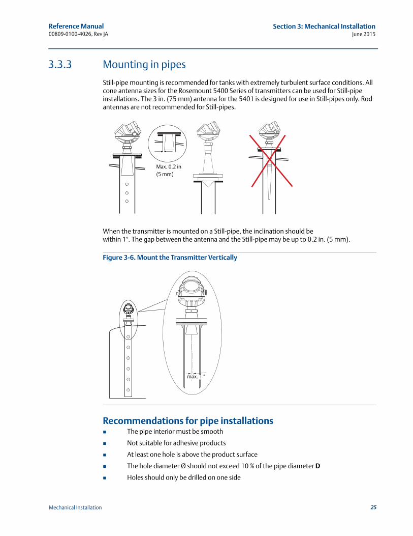
Still-pipe mounting is recommended for tanks with extremely turbulent surface conditions. All cone antenna sizes for the Rosemount 5400 Series of transmitters can be used for Still-pipe installations. The 3 in. (75 mm) antenna for the 5401 is designed for use in Still-pipes only. Rod antennas are not recommended for Still-pipes.
When the transmitter is mounted on a Still-pipe, the inclination should be within 1°. The gap between the antenna and the Still-pipe may be up to 0.2 in. (5 mm).
Figure 3-6. Mount the Transmitter Vertically
Recommendations for pipe installations The pipe interior must be smooth
Not suitable for adhesive products
At least one hole is above the product surface
The hole diameter Ø should not exceed 10 % of the pipe diameter D
Holes should only be drilled on one side
Max. 0.2 in (5 mm)
max. 1 °
25Mechanical Installation
Reference Manual00809-0100-4026, Rev JA
Section 3: Mechanical InstallationJune 2015
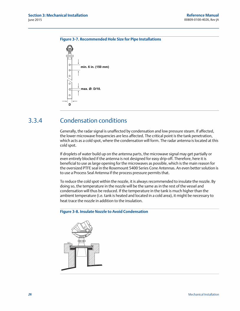
Figure 3-7. Recommended Hole Size for Pipe Installations
3.3.4 Condensation conditions
Generally, the radar signal is unaffected by condensation and low pressure steam. If affected, the lower microwave frequencies are less affected. The critical point is the tank penetration, which acts as a cold spot, where the condensation will form. The radar antenna is located at this cold spot.
If droplets of water build up on the antenna parts, the microwave signal may get partially or even entirely blocked if the antenna is not designed for easy drip-off. Therefore, here it is beneficial to use as large opening for the microwaves as possible, which is the main reason for the oversized PTFE seal in the Rosemount 5400 Series Cone Antennas. An even better solution is to use a Process Seal Antenna if the process pressure permits that.
To reduce the cold spot within the nozzle, it is always recommended to insulate the nozzle. By doing so, the temperature in the nozzle will be the same as in the rest of the vessel and condensation will thus be reduced. If the temperature in the tank is much higher than the ambient temperature (i.e. tank is heated and located in a cold area), it might be necessary to heat trace the nozzle in addition to the insulation.
Figure 3-8. Insulate Nozzle to Avoid Condensation
min. 6 in. (150 mm)
max. Ø: D/10.
D
26 Mechanical Installation
Reference Manual 00809-0100-4026, Rev JA
Section 3: Mechanical InstallationJune 2015
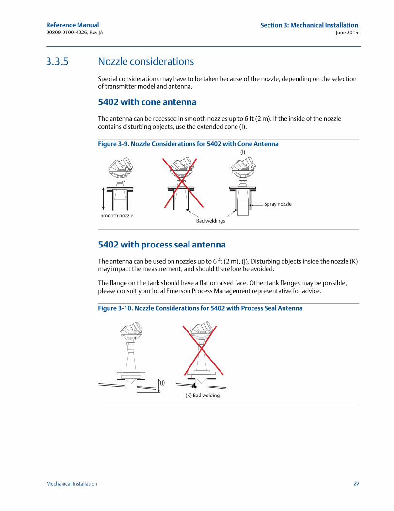
3.3.5 Nozzle considerations
Special considerations may have to be taken because of the nozzle, depending on the selection of transmitter model and antenna.
5402 with cone antenna
The antenna can be recessed in smooth nozzles up to 6 ft (2 m). If the inside of the nozzle contains disturbing objects, use the extended cone (I).
Figure 3-9. Nozzle Considerations for 5402 with Cone Antenna
5402 with process seal antenna
The antenna can be used on nozzles up to 6 ft (2 m), (J). Disturbing objects inside the nozzle (K) may impact the measurement, and should therefore be avoided.
The flange on the tank should have a flat or raised face. Other tank flanges may be possible, please consult your local Emerson Process Management representative for advice.
Figure 3-10. Nozzle Considerations for 5402 with Process Seal Antenna
Spray nozzle
(I)
Smooth nozzleBad weldings
(K) Bad welding
(J)
27Mechanical Installation
Reference Manual00809-0100-4026, Rev JA
Section 3: Mechanical InstallationJune 2015
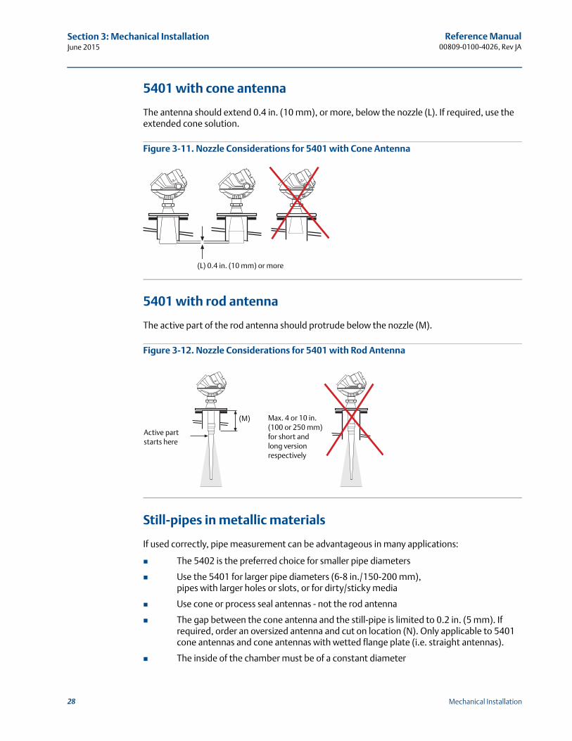
5401 with cone antenna
The antenna should extend 0.4 in. (10 mm), or more, below the nozzle (L). If required, use the extended cone solution.
Figure 3-11. Nozzle Considerations for 5401 with Cone Antenna
5401 with rod antenna
The active part of the rod antenna should protrude below the nozzle (M).
Figure 3-12. Nozzle Considerations for 5401 with Rod Antenna
Still-pipes in metallic materials
If used correctly, pipe measurement can be advantageous in many applications:
The 5402 is the preferred choice for smaller pipe diameters
Use the 5401 for larger pipe diameters (6-8 in./150-200 mm), pipes with larger holes or slots, or for dirty/sticky media
Use cone or process seal antennas - not the rod antenna
The gap between the cone antenna and the still-pipe is limited to 0.2 in. (5 mm). If required, order an oversized antenna and cut on location (N). Only applicable to 5401 cone antennas and cone antennas with wetted flange plate (i.e. straight antennas).
The inside of the chamber must be of a constant diameter
(L) 0.4 in. (10 mm) or more
Active part starts here
(M) Max. 4 or 10 in. (100 or 250 mm) for short and long version respectively
28 Mechanical Installation
Reference Manual 00809-0100-4026, Rev JA
Section 3: Mechanical InstallationJune 2015
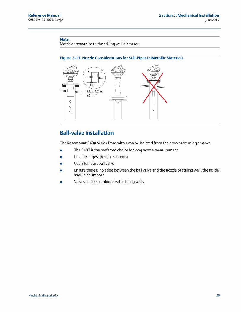
NoteMatch antenna size to the stilling well diameter.
Figure 3-13. Nozzle Considerations for Still-Pipes in Metallic Materials
Ball-valve installation
The Rosemount 5400 Series Transmitter can be isolated from the process by using a valve:
The 5402 is the preferred choice for long nozzle measurement
Use the largest possible antenna
Use a full-port ball valve
Ensure there is no edge between the ball valve and the nozzle or stilling well, the inside should be smooth
Valves can be combined with stilling wells
(N)
Max. 0.2 in. (5 mm)
29Mechanical Installation
Reference Manual00809-0100-4026, Rev JA
Section 3: Mechanical InstallationJune 2015
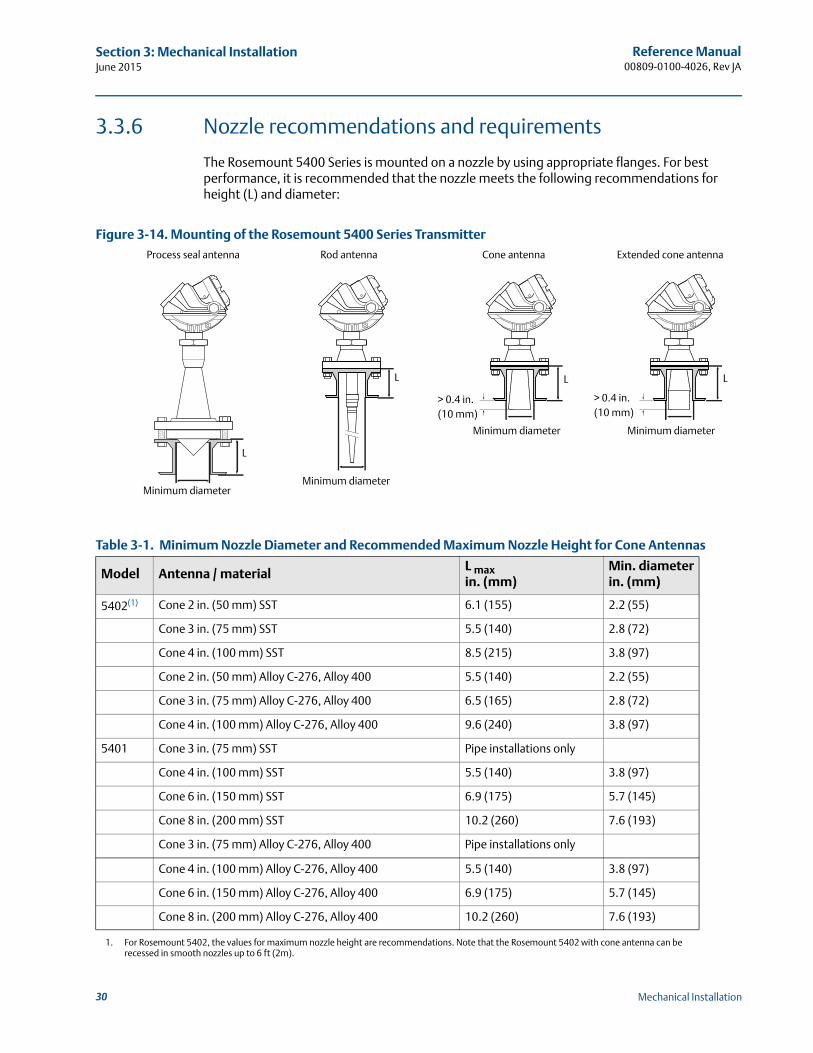
3.3.6 Nozzle recommendations and requirements
The Rosemount 5400 Series is mounted on a nozzle by using appropriate flanges. For best performance, it is recommended that the nozzle meets the following recommendations for height (L) and diameter:
Figure 3-14. Mounting of the Rosemount 5400 Series Transmitter
Table 3-1. Minimum Nozzle Diameter and Recommended Maximum Nozzle Height for Cone Antennas
Model Antenna / materialL max in. (mm)
Min. diameterin. (mm)
5402(1)
1. For Rosemount 5402, the values for maximum nozzle height are recommendations. Note that the Rosemount 5402 with cone antenna can be recessed in smooth nozzles up to 6 ft (2m).
Cone 2 in. (50 mm) SST 6.1 (155) 2.2 (55)
Cone 3 in. (75 mm) SST 5.5 (140) 2.8 (72)
Cone 4 in. (100 mm) SST 8.5 (215) 3.8 (97)
Cone 2 in. (50 mm) Alloy C-276, Alloy 400 5.5 (140) 2.2 (55)
Cone 3 in. (75 mm) Alloy C-276, Alloy 400 6.5 (165) 2.8 (72)
Cone 4 in. (100 mm) Alloy C-276, Alloy 400 9.6 (240) 3.8 (97)
5401 Cone 3 in. (75 mm) SST Pipe installations only
Cone 4 in. (100 mm) SST 5.5 (140) 3.8 (97)
Cone 6 in. (150 mm) SST 6.9 (175) 5.7 (145)
Cone 8 in. (200 mm) SST 10.2 (260) 7.6 (193)
Cone 3 in. (75 mm) Alloy C-276, Alloy 400 Pipe installations only
Cone 4 in. (100 mm) Alloy C-276, Alloy 400 5.5 (140) 3.8 (97)
Cone 6 in. (150 mm) Alloy C-276, Alloy 400 6.9 (175) 5.7 (145)
Cone 8 in. (200 mm) Alloy C-276, Alloy 400 10.2 (260) 7.6 (193)
L
Minimum diameter
> 0.4 in.(10 mm)
Minimum diameter
L
L
Minimum diameter
Minimum diameter
L
Process seal antenna Rod antenna Cone antenna Extended cone antenna
> 0.4 in.(10 mm)
30 Mechanical Installation
Reference Manual 00809-0100-4026, Rev JA
Section 3: Mechanical InstallationJune 2015
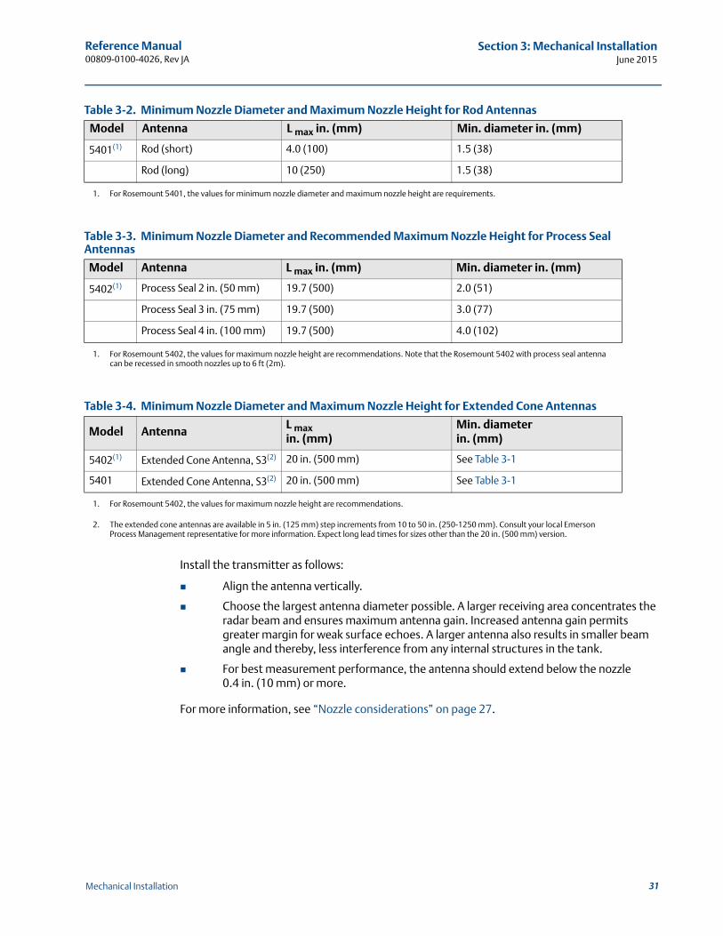
Table 3-2. Minimum Nozzle Diameter and Maximum Nozzle Height for Rod Antennas
Table 3-3. Minimum Nozzle Diameter and Recommended Maximum Nozzle Height for Process Seal Antennas
Table 3-4. Minimum Nozzle Diameter and Maximum Nozzle Height for Extended Cone Antennas
Install the transmitter as follows:
Align the antenna vertically.
Choose the largest antenna diameter possible. A larger receiving area concentrates the radar beam and ensures maximum antenna gain. Increased antenna gain permits greater margin for weak surface echoes. A larger antenna also results in smaller beam angle and thereby, less interference from any internal structures in the tank.
For best measurement performance, the antenna should extend below the nozzle 0.4 in. (10 mm) or more.
For more information, see “Nozzle considerations” on page 27.
Model Antenna L max in. (mm) Min. diameter in. (mm)
5401(1)
1. For Rosemount 5401, the values for minimum nozzle diameter and maximum nozzle height are requirements.
Rod (short) 4.0 (100) 1.5 (38)
Rod (long) 10 (250) 1.5 (38)
Model Antenna L max in. (mm) Min. diameter in. (mm)
5402(1)
1. For Rosemount 5402, the values for maximum nozzle height are recommendations. Note that the Rosemount 5402 with process seal antenna can be recessed in smooth nozzles up to 6 ft (2m).
Process Seal 2 in. (50 mm) 19.7 (500) 2.0 (51)
Process Seal 3 in. (75 mm) 19.7 (500) 3.0 (77)
Process Seal 4 in. (100 mm) 19.7 (500) 4.0 (102)
Model AntennaL max in. (mm)
Min. diameter in. (mm)
5402(1)
1. For Rosemount 5402, the values for maximum nozzle height are recommendations.
Extended Cone Antenna, S3(2)
2. The extended cone antennas are available in 5 in. (125 mm) step increments from 10 to 50 in. (250-1250 mm). Consult your local Emerson Process Management representative for more information. Expect long lead times for sizes other than the 20 in. (500 mm) version.
20 in. (500 mm) See Table 3-1
5401 Extended Cone Antenna, S3(2) 20 in. (500 mm) See Table 3-1
31Mechanical Installation
Reference Manual00809-0100-4026, Rev JA
Section 3: Mechanical InstallationJune 2015
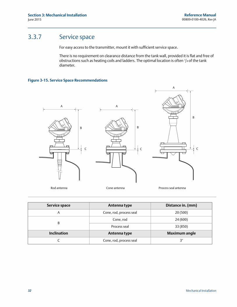
3.3.7 Service space
For easy access to the transmitter, mount it with sufficient service space.
There is no requirement on clearance distance from the tank wall, provided it is flat and free of obstructions such as heating coils and ladders. The optimal location is often 1/4 of the tank diameter.
Figure 3-15. Service Space Recommendations
Service space Antenna type Distance in. (mm)
A Cone, rod, process seal 20 (500)
BCone, rod 24 (600)
Process seal 33 (850)
Inclination Antenna type Maximum angle
C Cone, rod, process seal 3°
A
B
C
Rod antenna Cone antenna
A
B
CC
B
A
Process seal antenna
32 Mechanical Installation
Reference Manual 00809-0100-4026, Rev JA
Section 3: Mechanical InstallationJune 2015
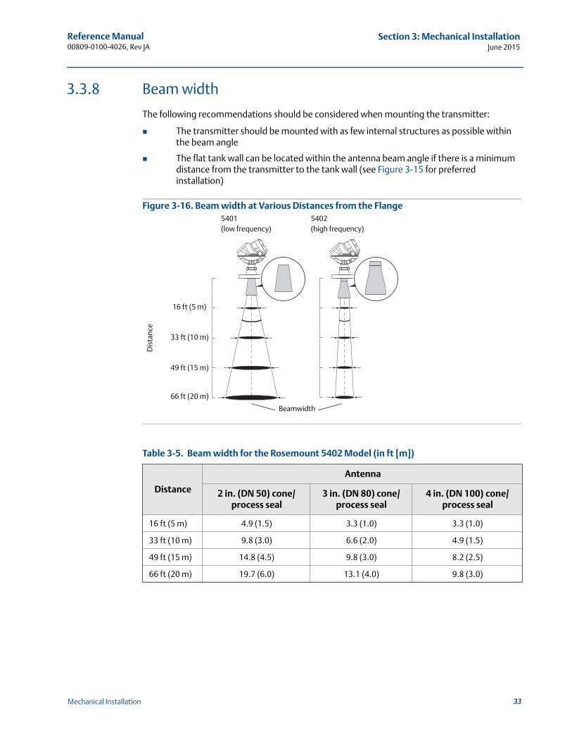
3.3.8 Beam width
The following recommendations should be considered when mounting the transmitter:
The transmitter should be mounted with as few internal structures as possible within the beam angle
The flat tank wall can be located within the antenna beam angle if there is a minimum distance from the transmitter to the tank wall (see Figure 3-15 for preferred installation)
Figure 3-16. Beam width at Various Distances from the Flange
Table 3-5. Beam width for the Rosemount 5402 Model (in ft [m])
Distance
Antenna
2 in. (DN 50) cone/process seal
3 in. (DN 80) cone/process seal
4 in. (DN 100) cone/process seal
16 ft (5 m) 4.9 (1.5) 3.3 (1.0) 3.3 (1.0)
33 ft (10 m) 9.8 (3.0) 6.6 (2.0) 4.9 (1.5)
49 ft (15 m) 14.8 (4.5) 9.8 (3.0) 8.2 (2.5)
66 ft (20 m) 19.7 (6.0) 13.1 (4.0) 9.8 (3.0)
Dis
tanc
e
5401(low frequency)
5402(high frequency)
16 ft (5 m)
33 ft (10 m)
49 ft (15 m)
66 ft (20 m)
Beamwidth
33Mechanical Installation
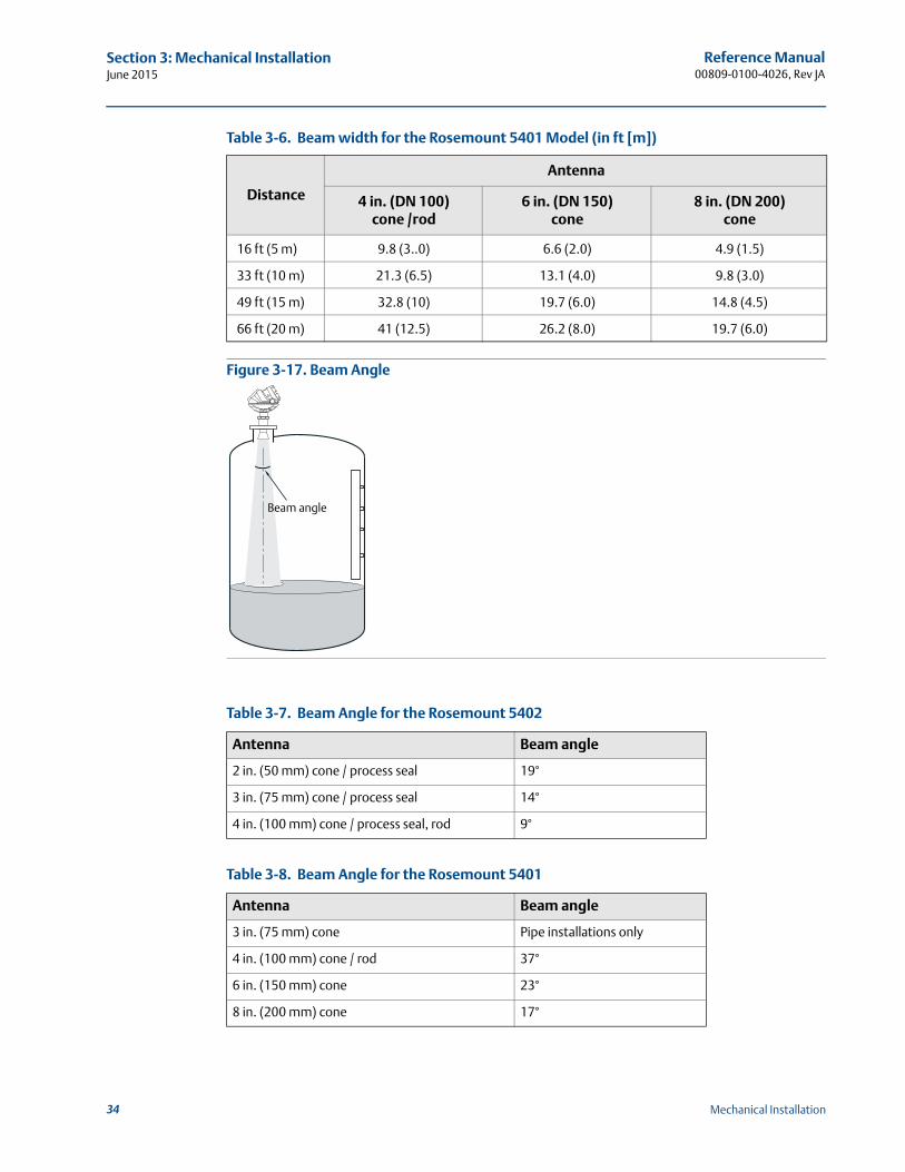
Reference Manual00809-0100-4026, Rev JA
Section 3: Mechanical InstallationJune 2015
Table 3-6. Beam width for the Rosemount 5401 Model (in ft [m])
Figure 3-17. Beam Angle
Table 3-7. Beam Angle for the Rosemount 5402
Table 3-8. Beam Angle for the Rosemount 5401
Distance
Antenna
4 in. (DN 100) cone /rod
6 in. (DN 150) cone
8 in. (DN 200) cone
16 ft (5 m) 9.8 (3..0) 6.6 (2.0) 4.9 (1.5)
33 ft (10 m) 21.3 (6.5) 13.1 (4.0) 9.8 (3.0)
49 ft (15 m) 32.8 (10) 19.7 (6.0) 14.8 (4.5)
66 ft (20 m) 41 (12.5) 26.2 (8.0) 19.7 (6.0)
Antenna Beam angle
2 in. (50 mm) cone / process seal 19°
3 in. (75 mm) cone / process seal 14°
4 in. (100 mm) cone / process seal, rod 9°
Antenna Beam angle
3 in. (75 mm) cone Pipe installations only
4 in. (100 mm) cone / rod 37°
6 in. (150 mm) cone 23°
8 in. (200 mm) cone 17°
Beam angle
34 Mechanical Installation
Reference Manual 00809-0100-4026, Rev JA
Section 3: Mechanical InstallationJune 2015
3.3.9 Vessel characteristics
Heating coils, agitators and other objects in the tank may lead to disturbing echoes and noise in the measurement signal. Vertical structures cause minimal effect since the radar signal is scattered rather than directed back to the antenna.
The shape of the tank bottom affects the measurement signal when the product surface is close to the tank bottom. The Rosemount 5400 Series has built-in functions which optimize measurement performance for various bottom shapes (see “Tank type and tank bottom type” on page 76).
3.3.10 Disturbing objects
The Rosemount 5400 Series transmitter should be mounted so that objects such as heating coils, ladders, etc. are not in the radar signal path. These objects may cause false echoes resulting in reduced measurement performance. However, the transmitter has built-in functions designed to reduce the influence from disturbing objects where such objects cannot be totally avoided.
The Rosemount 5402 has a narrower radar beam that is particularly suitable in installations with tall or narrow nozzles, or nozzles close to the tank wall. It may also be used to avoid disturbing objects in the tank.
3.3.11 Valves
The Rosemount 5400 Series transmitter can be isolated from the process by using a valve:
Use a full-port ball valve.
The 5402 is the required and the Process Seal Antenna is the preferred choice, since it does not require a spool piece. The cone antenna can also be used.
Ensure there is no edge between the ball valve and the nozzle/pipe, the inside should be smooth.
Valves can be combined with stilling wells.
35Mechanical Installation
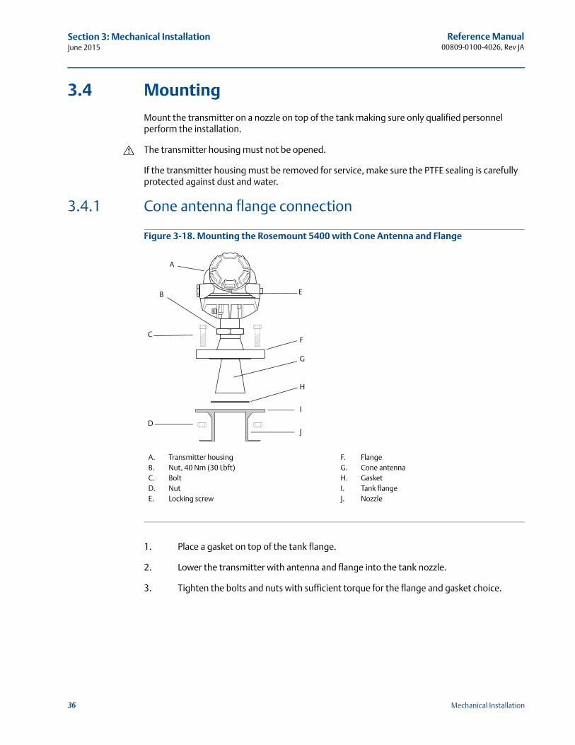
Reference Manual00809-0100-4026, Rev JA
Section 3: Mechanical InstallationJune 2015
3.4 Mounting
Mount the transmitter on a nozzle on top of the tank making sure only qualified personnel perform the installation.
The transmitter housing must not be opened.
If the transmitter housing must be removed for service, make sure the PTFE sealing is carefully protected against dust and water.
3.4.1 Cone antenna flange connection
Figure 3-18. Mounting the Rosemount 5400 with Cone Antenna and Flange
1. Place a gasket on top of the tank flange.
2. Lower the transmitter with antenna and flange into the tank nozzle.
3. Tighten the bolts and nuts with sufficient torque for the flange and gasket choice.
A
C
H
F
I
G
DJ
EB
A. Transmitter housingB. Nut, 40 Nm (30 Lbft)C. BoltD. NutE. Locking screw
F. FlangeG. Cone antennaH. GasketI. Tank flangeJ. Nozzle
36 Mechanical Installation
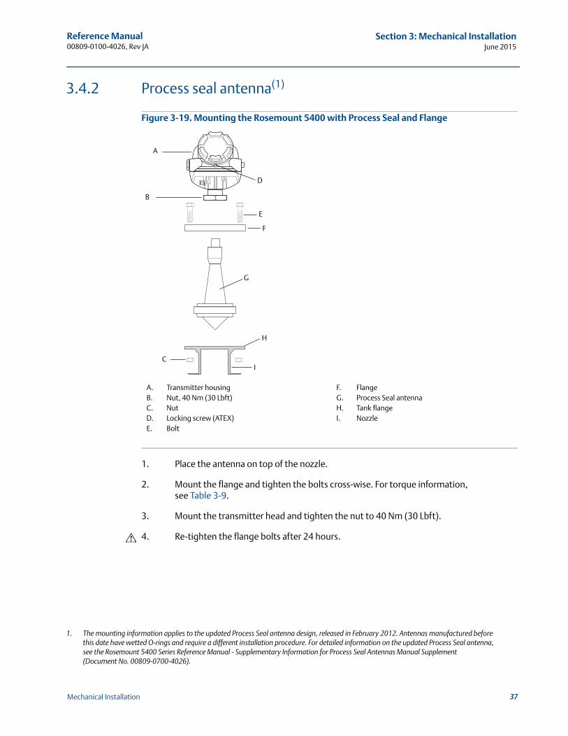
Reference Manual 00809-0100-4026, Rev JA
Section 3: Mechanical InstallationJune 2015
3.4.2 Process seal antenna(1)
Figure 3-19. Mounting the Rosemount 5400 with Process Seal and Flange
1. Place the antenna on top of the nozzle.
2. Mount the flange and tighten the bolts cross-wise. For torque information, see Table 3-9.
3. Mount the transmitter head and tighten the nut to 40 Nm (30 Lbft).
4. Re-tighten the flange bolts after 24 hours.
1. The mounting information applies to the updated Process Seal antenna design, released in February 2012. Antennas manufactured before this date have wetted O-rings and require a different installation procedure. For detailed information on the updated Process Seal antenna, see the Rosemount 5400 Series Reference Manual - Supplementary Information for Process Seal Antennas Manual Supplement (Document No. 00809-0700-4026).
E
F
A
B
D
G
H
IC
A. Transmitter housingB. Nut, 40 Nm (30 Lbft)C. NutD. Locking screw (ATEX)E. Bolt
F. FlangeG. Process Seal antennaH. Tank flangeI. Nozzle
37Mechanical Installation
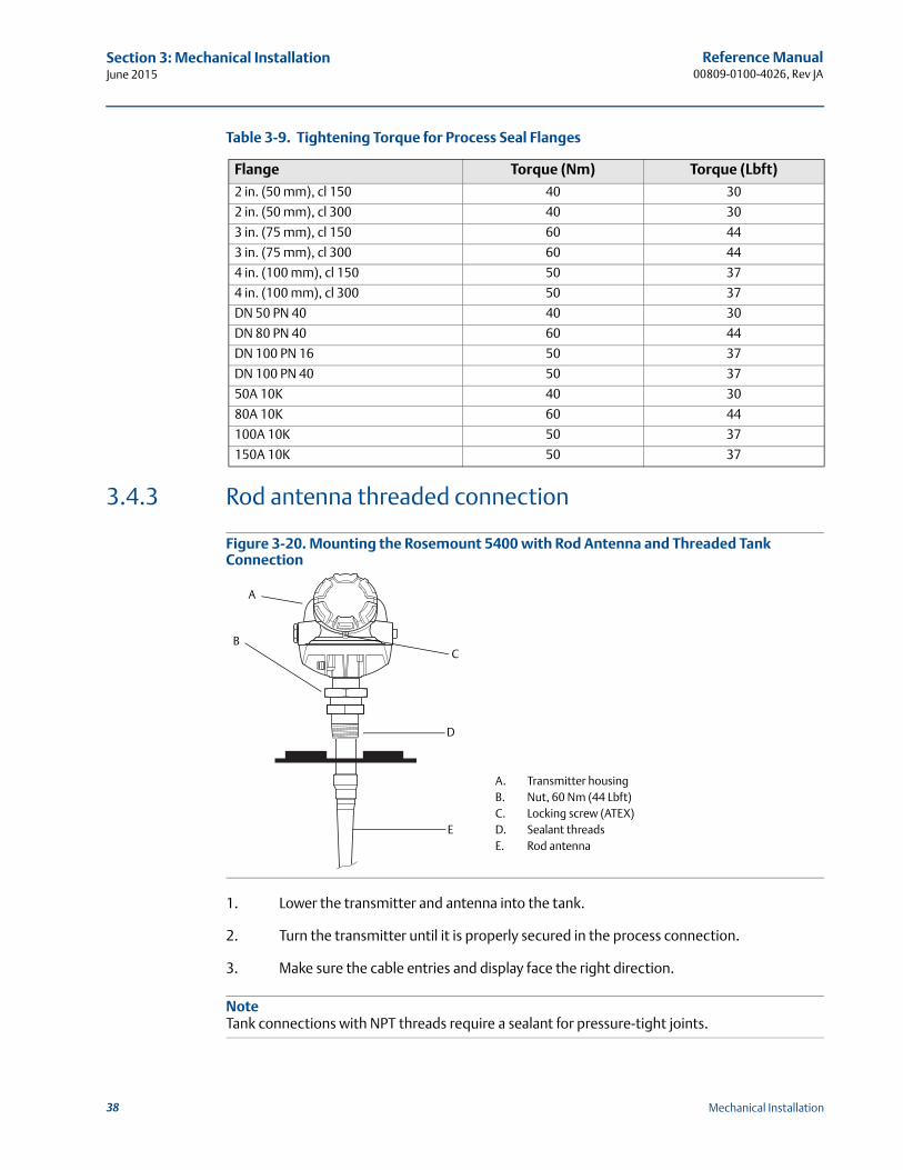
Reference Manual00809-0100-4026, Rev JA
Section 3: Mechanical InstallationJune 2015
Table 3-9. Tightening Torque for Process Seal Flanges
3.4.3 Rod antenna threaded connection
Figure 3-20. Mounting the Rosemount 5400 with Rod Antenna and Threaded Tank Connection
1. Lower the transmitter and antenna into the tank.
2. Turn the transmitter until it is properly secured in the process connection.
3. Make sure the cable entries and display face the right direction.
NoteTank connections with NPT threads require a sealant for pressure-tight joints.
Flange Torque (Nm) Torque (Lbft)
2 in. (50 mm), cl 150 40 30
2 in. (50 mm), cl 300 40 30
3 in. (75 mm), cl 150 60 44
3 in. (75 mm), cl 300 60 44
4 in. (100 mm), cl 150 50 37
4 in. (100 mm), cl 300 50 37
DN 50 PN 40 40 30
DN 80 PN 40 60 44
DN 100 PN 16 50 37
DN 100 PN 40 50 37
50A 10K 40 30
80A 10K 60 44
100A 10K 50 37
150A 10K 50 37
A. Transmitter housingB. Nut, 60 Nm (44 Lbft)C. Locking screw (ATEX)D. Sealant threadsE. Rod antenna
E
D
C
A
B
38 Mechanical Installation
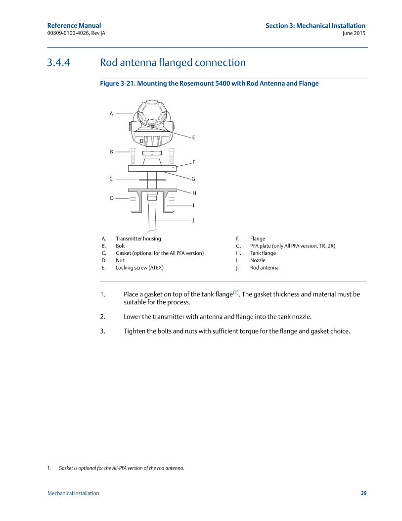
Reference Manual 00809-0100-4026, Rev JA
Section 3: Mechanical InstallationJune 2015
3.4.4 Rod antenna flanged connection
Figure 3-21. Mounting the Rosemount 5400 with Rod Antenna and Flange
1. Place a gasket on top of the tank flange(1). The gasket thickness and material must be suitable for the process.
2. Lower the transmitter with antenna and flange into the tank nozzle.
3. Tighten the bolts and nuts with sufficient torque for the flange and gasket choice.
1. Gasket is optional for the All-PFA version of the rod antenna.
C
F
H
J
G
A
B
D
E
I
A. Transmitter housingB. BoltC. Gasket (optional for the All PFA version)D. NutE. Locking screw (ATEX)
F. FlangeG. PFA plate (only All PFA version, 1R, 2R)H. Tank flangeI. NozzleJ. Rod antenna
39Mechanical Installation
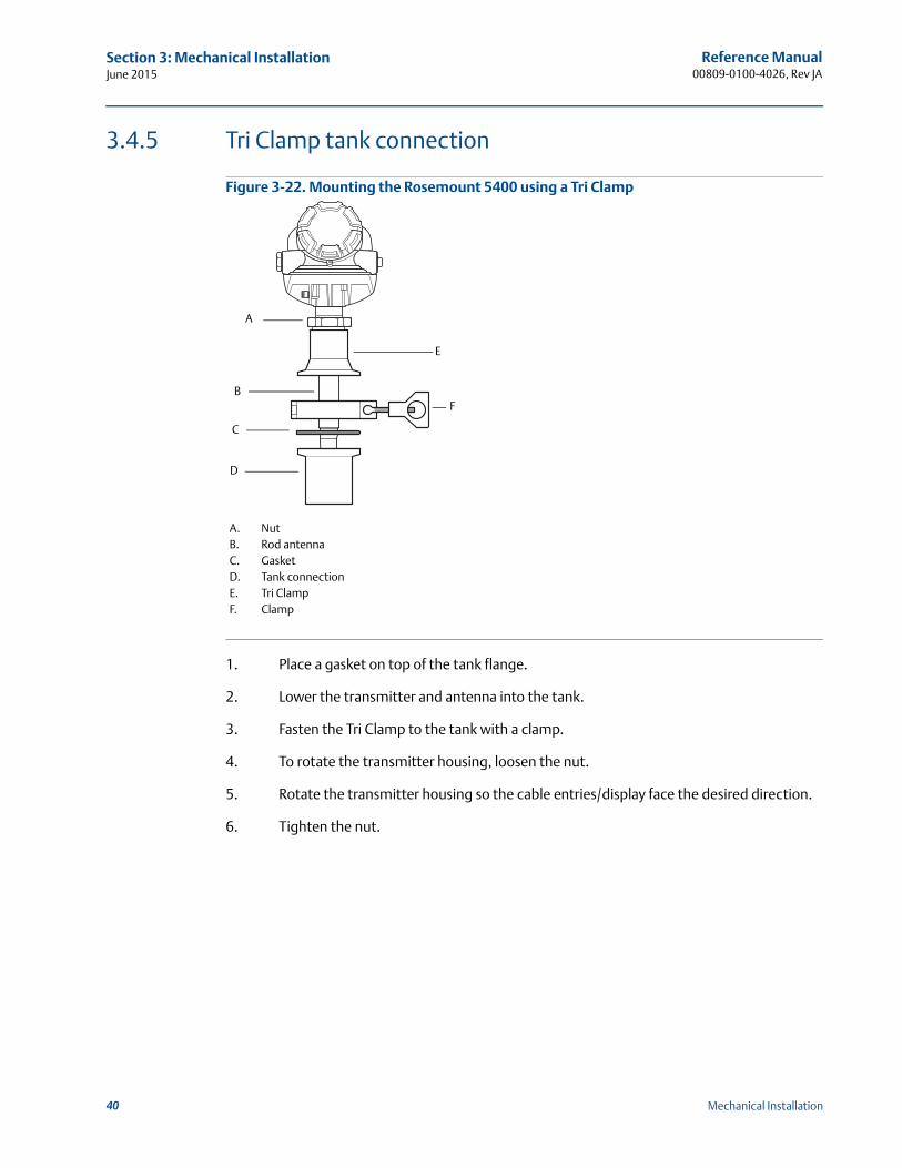
Reference Manual00809-0100-4026, Rev JA
Section 3: Mechanical InstallationJune 2015
3.4.5 Tri Clamp tank connection
Figure 3-22. Mounting the Rosemount 5400 using a Tri Clamp
1. Place a gasket on top of the tank flange.
2. Lower the transmitter and antenna into the tank.
3. Fasten the Tri Clamp to the tank with a clamp.
4. To rotate the transmitter housing, loosen the nut.
5. Rotate the transmitter housing so the cable entries/display face the desired direction.
6. Tighten the nut.
C
B
A
D
E
F
A. NutB. Rod antennaC. GasketD. Tank connectionE. Tri ClampF. Clamp
40 Mechanical Installation
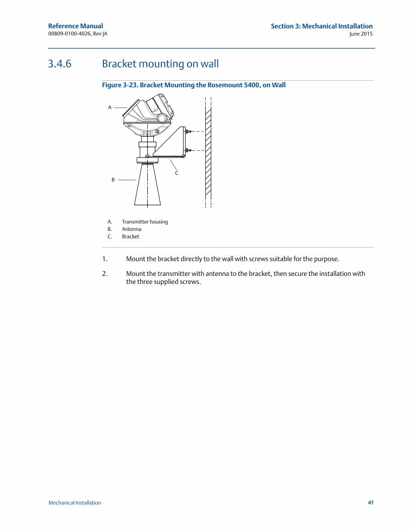
Reference Manual 00809-0100-4026, Rev JA
Section 3: Mechanical InstallationJune 2015
3.4.6 Bracket mounting on wall
Figure 3-23. Bracket Mounting the Rosemount 5400, on Wall
1. Mount the bracket directly to the wall with screws suitable for the purpose.
2. Mount the transmitter with antenna to the bracket, then secure the installation with the three supplied screws.
A
CB
A. Transmitter housingB. AntennaC. Bracket
41Mechanical Installation
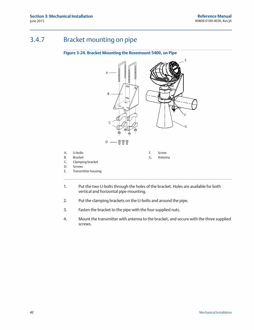
Reference Manual00809-0100-4026, Rev JA
Section 3: Mechanical InstallationJune 2015
3.4.7 Bracket mounting on pipe
Figure 3-24. Bracket Mounting the Rosemount 5400, on Pipe
1. Put the two U-bolts through the holes of the bracket. Holes are available for both vertical and horizontal pipe mounting.
2. Put the clamping brackets on the U-bolts and around the pipe.
3. Fasten the bracket to the pipe with the four supplied nuts.
4. Mount the transmitter with antenna to the bracket, and secure with the three supplied screws.
CG
E
B
A
D
F
A. U-boltsB. BracketC. Clamping bracketD. ScrewsE. Transmitter housing
F. ScrewG. Antenna
42 Mechanical Installation

Reference Manual 00809-0100-4026, Rev JA
Section 4: Electrical InstallationJune 2015
Section 4 Electrical Installation
Safety messages . . . . . . . . . . . . . . . . . . . . . . . . . . . . . . . . . . . . . . . . . . . . . . . . . . . . . . . . . . . . page 43Wiring and power supply requirements . . . . . . . . . . . . . . . . . . . . . . . . . . . . . . . . . . . . . . . . page 44Cable/conduit entries . . . . . . . . . . . . . . . . . . . . . . . . . . . . . . . . . . . . . . . . . . . . . . . . . . . . . . . page 45Grounding . . . . . . . . . . . . . . . . . . . . . . . . . . . . . . . . . . . . . . . . . . . . . . . . . . . . . . . . . . . . . . . . . page 46Cable selection . . . . . . . . . . . . . . . . . . . . . . . . . . . . . . . . . . . . . . . . . . . . . . . . . . . . . . . . . . . . . page 46Hazardous areas . . . . . . . . . . . . . . . . . . . . . . . . . . . . . . . . . . . . . . . . . . . . . . . . . . . . . . . . . . . . page 47External circuit breaker . . . . . . . . . . . . . . . . . . . . . . . . . . . . . . . . . . . . . . . . . . . . . . . . . . . . . . page 47HART . . . . . . . . . . . . . . . . . . . . . . . . . . . . . . . . . . . . . . . . . . . . . . . . . . . . . . . . . . . . . . . . . . . . . . page 49FOUNDATION fieldbus . . . . . . . . . . . . . . . . . . . . . . . . . . . . . . . . . . . . . . . . . . . . . . . . . . . . . . . . . page 55HART to Modbus Converter (HMC) . . . . . . . . . . . . . . . . . . . . . . . . . . . . . . . . . . . . . . . . . . . . page 60Establish HART communication . . . . . . . . . . . . . . . . . . . . . . . . . . . . . . . . . . . . . . . . . . . . . . . page 66Optional devices . . . . . . . . . . . . . . . . . . . . . . . . . . . . . . . . . . . . . . . . . . . . . . . . . . . . . . . . . . . . page 69
4.1 Safety messages
Procedures and instructions in this section may require special precautions to ensure the safety of the personnel performing the operations. Information that raises potential safety issues is indicated by a warning symbol ( ). Refer to the following safety messages before performing an operation preceded by this symbol.
43Electrical Installation

Reference Manual00809-0100-4026, Rev JA
Section 4: Electrical InstallationJune 2015
Additional warnings or restrictions may apply depending on type of Hazardous approval. See Appendix B: Product Certifications for details.
4.2 Wiring and power supply requirements
Wiring and power supply requirements can be dependent upon the approval certification. As with all FOUNDATION™ fieldbus requirements, a conditioned power supply and terminating resistors are required for proper operation.
Failure to follow safe installation and service guidelines could result in death or serious injury.
Make sure only qualified personnel perform installation or service. Use the equipment only as specified in this manual. Failure to do so may impair the
protection provided by the equipment. Any substitution of non-recognized spare parts may jeopardize safety. Repair, e.g.
substitution of components etc. may also jeopardize safety and is under no circumstances allowed.
Do not perform any service other than those contained in this manual unless you are qualified.
Process leaks could result in death or serious injury.
Make sure that the transmitter is handled carefully. If the process seal is damaged, gas might escape from the tank if the transmitter head is removed from the antenna.
Explosions could result in death or serious injury.
Verify that the operating environment of the transmitter is consistent with the appropriate hazardous locations specifications.
In an Explosion-proof/Flameproof installation, do not remove the transmitter cover when power is applied to the unit.
Before connecting a Field Communicator in an explosive atmosphere, make sure the instruments in the loop are installed in accordance with intrinsically safe or non-incendive field wiring practices.
Electrical shock can result in death or serious injury.
Avoid contact with the leads and terminals. High voltage that may be present on leads can cause electrical shock.
Make sure the main power to the Rosemount 5400 Series Transmitter is off and the lines to any other external power source are disconnected or not powered while wiring the transmitter.
High voltage that may be present on leads could cause electrical shock.
Avoid contact with leads and terminals. Make sure the main power to the Rosemount 5400 Transmitter is off and the lines to
any other external power source are disconnected or not powered while wiring the gauge.
Antennas with non-conducting surfaces.
Antennas with non-conducting surfaces (e.g. rod antenna and process seal antenna) may generate an ignition-capable level of electrostatic charge under extreme conditions.Therefore, when the antenna is used in a potentially explosive atmosphere, appropriate measures must be taken to prevent electrostatic discharge.
44 Electrical Installation
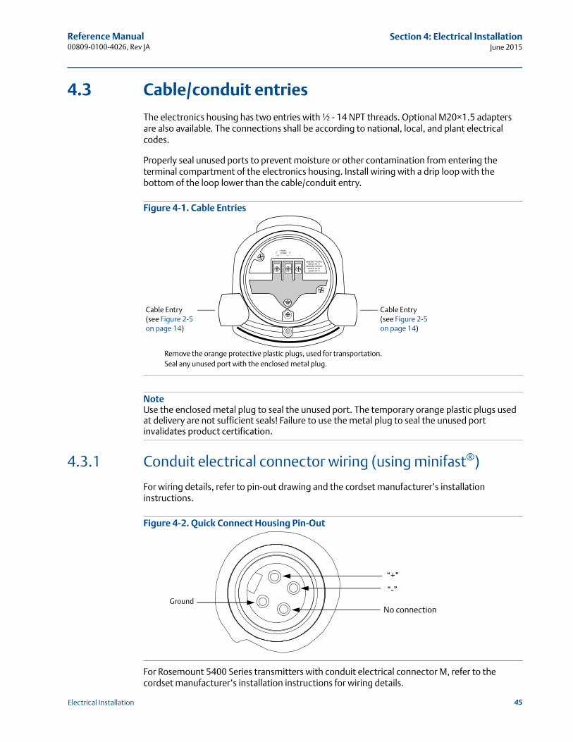
Reference Manual 00809-0100-4026, Rev JA
Section 4: Electrical InstallationJune 2015
4.3 Cable/conduit entries
The electronics housing has two entries with ½ - 14 NPT threads. Optional M20×1.5 adapters are also available. The connections shall be according to national, local, and plant electrical codes.
Properly seal unused ports to prevent moisture or other contamination from entering the terminal compartment of the electronics housing. Install wiring with a drip loop with the bottom of the loop lower than the cable/conduit entry.
Figure 4-1. Cable Entries
NoteUse the enclosed metal plug to seal the unused port. The temporary orange plastic plugs used at delivery are not sufficient seals! Failure to use the metal plug to seal the unused port invalidates product certification.
4.3.1 Conduit electrical connector wiring (using minifast®)
For wiring details, refer to pin-out drawing and the cordset manufacturer’s installation instructions.
Figure 4-2. Quick Connect Housing Pin-Out
For Rosemount 5400 Series transmitters with conduit electrical connector M, refer to the cordset manufacturer’s installation instructions for wiring details.
Remove the orange protective plastic plugs, used for transportation.Seal any unused port with the enclosed metal plug.
Cable Entry(see Figure 2-5 on page 14)
Cable Entry (see Figure 2-5 on page 14)
“+”
“-”
No connectionGround
45Electrical Installation
Reference Manual00809-0100-4026, Rev JA
Section 4: Electrical InstallationJune 2015
4.4 Grounding
When wiring the transmitters, the grounding should be completed such that:
The loop is grounded at the power supply.
When transmitters are installed on metal tanks, ensure there is a metal-to-metal connection between the device and the tank.
If the tank is non-metallic, the housing must be grounded to an earth ground that is separate from the power supply. The external ground terminal may be used for this purpose.
If the tank is cathodically protected, the housing must be grounded to an earth ground that is outside of the cathodic protection system ground. Use the external terminal for this purpose.
When transient protection terminal block is used, the ground wire should be separate from the signal wire. Use the external ground terminal.
Make sure grounding is done (including IS ground inside Terminal compartment) according to Hazardous Locations Certifications, national and local electrical codes.
The most effective transmitter housing grounding method is a direct connection to earth ground with minimal (< 1 ) impedance.
NoteGrounding the transmitter housing using the threaded conduit connection may not provide a sufficient ground. The transient protection terminal block will not provide transient protection unless the transmitter housing is properly grounded. Use the above guidelines to ground the transmitter housing. Do not run transient protection ground wire with signal wiring; the ground wire may carry excessive current if a lightning strike occurs.
NoteAfter installation and commissioning, make sure that no ground currents exist from high ground potential differences in the installation.
4.5 Cable selection
Use shielded twisted pair wiring for the Rosemount 5400 Series. The cables must be suitable for the supply voltage and approved for use in hazardous areas, where applicable. For instance, in the U.S., explosion-proof conduits must be used in the vicinity of the vessel. For the ATEX flameproof approval version of the Rosemount 5400 Series, suitable conduits with sealing device or flameproof cable glands must be used depending on local requirements.
Use 18 AWG to 12 AWG wiring to minimize the voltage drop to the transmitter.
For Modbus® units (RS-485 bus), the following rules apply:
2 cables are used for communication: 24 AWG shielded twisted pair wiring is recommended to get an impedance of 120
2 cables are used for power: AWG 16-18 cables must be used
46 Electrical Installation

Reference Manual 00809-0100-4026, Rev JA
Section 4: Electrical InstallationJune 2015
NoteAvoid running instrument cable next to power cables in cable trays or near heavy electrical equipment.
It is important that the instrument cable shield be:- trimmed close and insulated from touching the transmitter housing- continuously connected throughout the segment- connected to a good earth ground at the power supply end
4.6 Hazardous areas
When the Rosemount 5400 Series transmitter is installed in a hazardous area, all national and local regulations and specifications in applicable certificates must be observed.
4.7 External circuit breaker
For compliance with Low Voltage Directive 2006/95/EC, an external circuit breaker should be installed.
4.7.1 Connecting the transmitter
The Rosemount 5400 Series accepts power supplies ranging from 16 Vdc to 42.4 Vdc. It uses 4-20 mA power superimposed with a HART® signal.
To connect the transmitter:
1. Verify that the power supply is disconnected.
2. Remove the terminal block cover (see Figure 4-3).
3. Pull the cable through the cable gland/conduit. For explosion-proof/ flameproof installations, only use cable glands or conduit entry devices certified explosion-proof or flameproof. Install the wiring with a drip loop where the bottom of the loop must be lower than the cable/conduit entry.
4. To connect the wires, see the illustrations on the following pages.
5. Remove the orange protective plastic plugs used for transportation. Seal any unused port with the enclosed metal plug.
6. Mount the cover and make sure it is fully engaged to meet explosion-proof requirements (adapters are required if M20 glands are used). For ATEX, IECEx, NEPSI, INMETRO, and TIIS installations, lock the cover with the locking screw.
7. Connect the power supply.
NoteUse PTFE tape or other sealant at the NPT threads in the cable entries.
47Electrical Installation
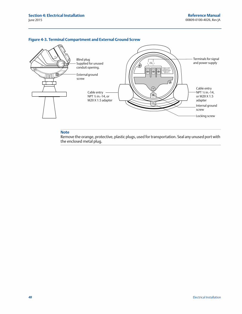
Reference Manual00809-0100-4026, Rev JA
Section 4: Electrical InstallationJune 2015
Figure 4-3. Terminal Compartment and External Ground Screw
NoteRemove the orange, protective, plastic plugs, used for transportation. Seal any unused port with the enclosed metal plug.
Cable entryNPT ½ in.-14, or M20 X 1.5 adapter
External ground screw
Blind plugSupplied for unused conduit opening.
Terminals for signal and power supply
Cable entryNPT ½ in.-14, or M20 X 1.5 adapter
Locking screw
Internal ground screw
48 Electrical Installation
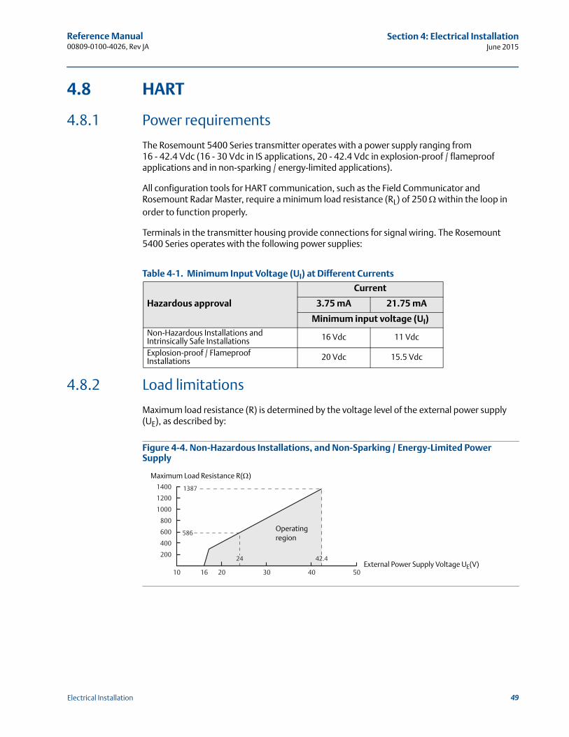
Reference Manual 00809-0100-4026, Rev JA
Section 4: Electrical InstallationJune 2015
4.8 HART
4.8.1 Power requirements
The Rosemount 5400 Series transmitter operates with a power supply ranging from 16 - 42.4 Vdc (16 - 30 Vdc in IS applications, 20 - 42.4 Vdc in explosion-proof / flameproof applications and in non-sparking / energy-limited applications).
All configuration tools for HART communication, such as the Field Communicator and Rosemount Radar Master, require a minimum load resistance (RL) of 250 within the loop in order to function properly.
Terminals in the transmitter housing provide connections for signal wiring. The Rosemount 5400 Series operates with the following power supplies:
Table 4-1. Minimum Input Voltage (UI) at Different Currents
4.8.2 Load limitations
Maximum load resistance (R) is determined by the voltage level of the external power supply (UE), as described by:
Figure 4-4. Non-Hazardous Installations, and Non-Sparking / Energy-Limited Power Supply
Hazardous approval
Current
3.75 mA 21.75 mA
Minimum input voltage (UI)
Non-Hazardous Installations and Intrinsically Safe Installations 16 Vdc 11 Vdc
Explosion-proof / Flameproof Installations 20 Vdc 15.5 Vdc
10 2016 30
200
400
600
800
1000
1200
1400
40 50
42.424
586
1387
External Power Supply Voltage UE(V)
Maximum Load Resistance R()
Operating region
49Electrical Installation
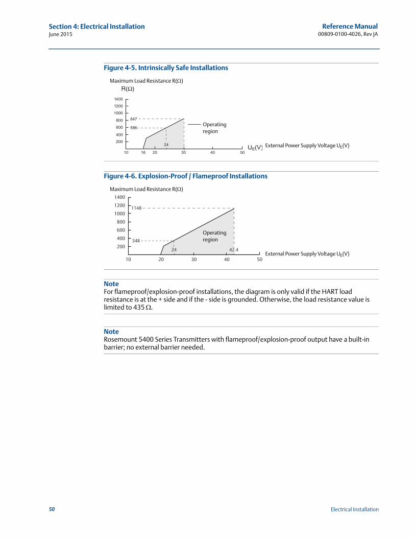
Reference Manual00809-0100-4026, Rev JA
Section 4: Electrical InstallationJune 2015
Figure 4-5. Intrinsically Safe Installations
Figure 4-6. Explosion-Proof / Flameproof Installations
NoteFor flameproof/explosion-proof installations, the diagram is only valid if the HART load resistance is at the + side and if the - side is grounded. Otherwise, the load resistance value is limited to 435 .
NoteRosemount 5400 Series Transmitters with flameproof/explosion-proof output have a built-in barrier; no external barrier needed.
External Power Supply Voltage UE(V)
Maximum Load Resistance R()
Operating region
10 20 30
200
400
600
800
1000
1200
1400
40 50
24 42.4
1148
348
External Power Supply Voltage UE(V)
Maximum Load Resistance R()
Operating region
50 Electrical Installation
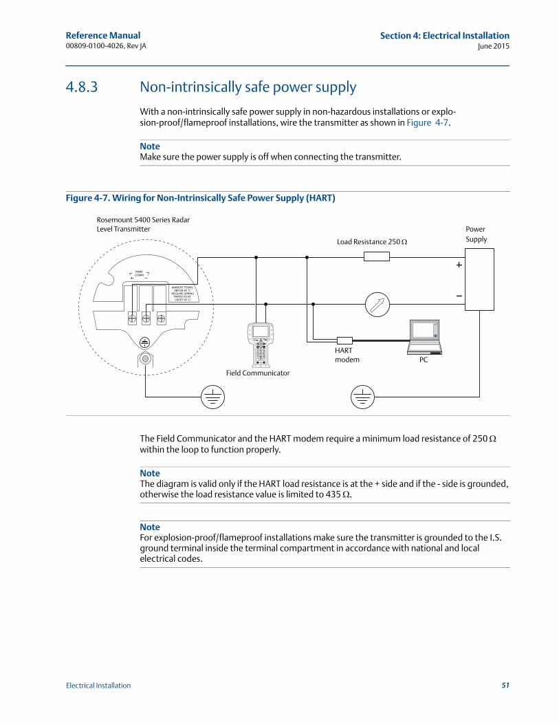
Reference Manual 00809-0100-4026, Rev JA
Section 4: Electrical InstallationJune 2015
4.8.3 Non-intrinsically safe power supply
With a non-intrinsically safe power supply in non-hazardous installations or explo-sion-proof/flameproof installations, wire the transmitter as shown in Figure 4-7.
NoteMake sure the power supply is off when connecting the transmitter.
Figure 4-7. Wiring for Non-Intrinsically Safe Power Supply (HART)
The Field Communicator and the HART modem require a minimum load resistance of 250 within the loop to function properly.
NoteThe diagram is valid only if the HART load resistance is at the + side and if the - side is grounded, otherwise the load resistance value is limited to 435 .
NoteFor explosion-proof/flameproof installations make sure the transmitter is grounded to the I.S. ground terminal inside the terminal compartment in accordance with national and local electrical codes.
Rosemount 5400 Series Radar Level Transmitter
Field Communicator
HARTmodem
Load Resistance 250
PowerSupply
PC
51Electrical Installation
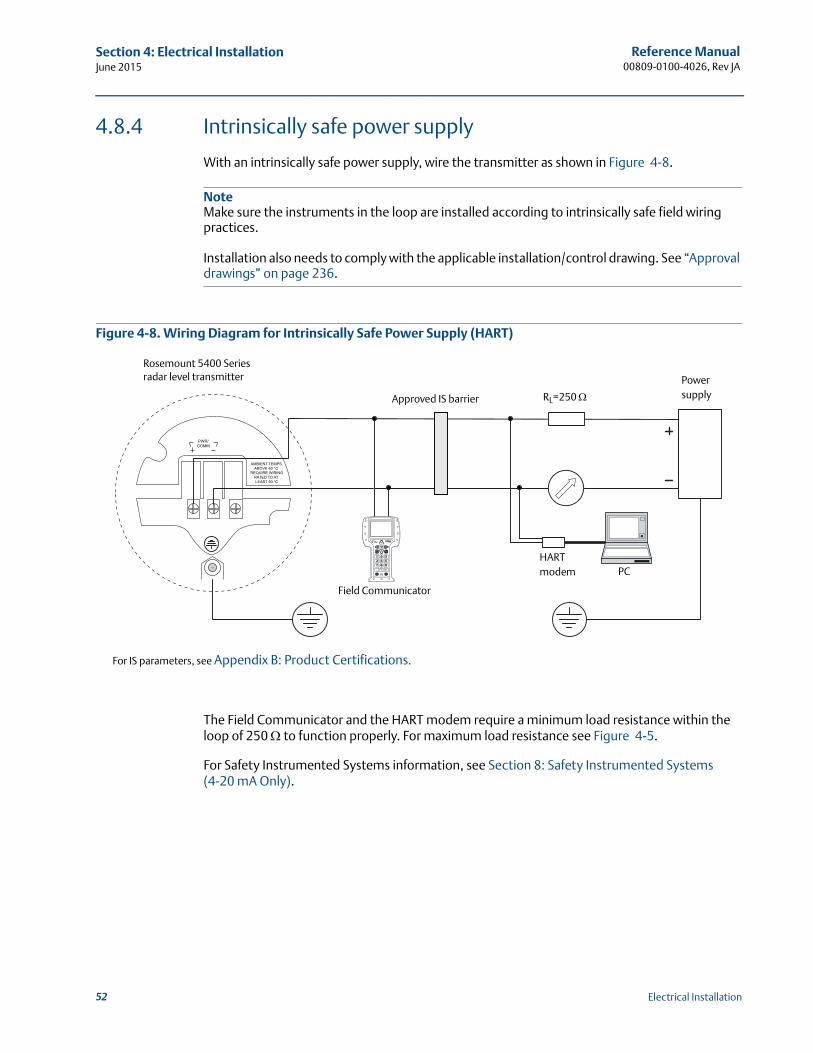
Reference Manual00809-0100-4026, Rev JA
Section 4: Electrical InstallationJune 2015
4.8.4 Intrinsically safe power supply
With an intrinsically safe power supply, wire the transmitter as shown in Figure 4-8.
NoteMake sure the instruments in the loop are installed according to intrinsically safe field wiring practices.
Installation also needs to comply with the applicable installation/control drawing. See “Approval drawings” on page 236.
Figure 4-8. Wiring Diagram for Intrinsically Safe Power Supply (HART)
The Field Communicator and the HART modem require a minimum load resistance within the loop of 250 to function properly. For maximum load resistance see Figure 4-5.
For Safety Instrumented Systems information, see Section 8: Safety Instrumented Systems (4-20 mA Only).
For IS parameters, see Appendix B: Product Certifications.
Rosemount 5400 Series radar level transmitter
Approved IS barrier RL=250
Powersupply
Field Communicator
HARTmodem PC
52 Electrical Installation
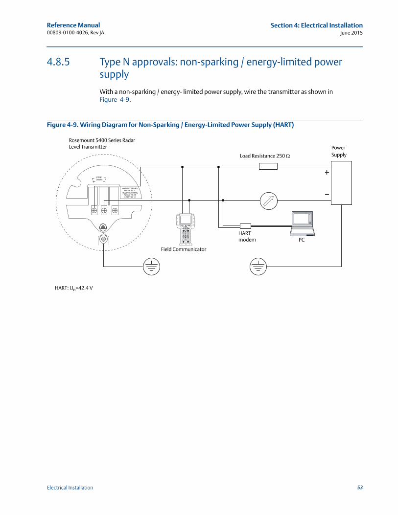
Reference Manual 00809-0100-4026, Rev JA
Section 4: Electrical InstallationJune 2015
4.8.5 Type N approvals: non-sparking / energy-limited power supply
With a non-sparking / energy- limited power supply, wire the transmitter as shown in Figure 4-9.
Figure 4-9. Wiring Diagram for Non-Sparking / Energy-Limited Power Supply (HART)
Rosemount 5400 Series Radar Level Transmitter
Field Communicator
HARTmodem
Load Resistance 250
PowerSupply
PC
HART: Un=42.4 V
53Electrical Installation
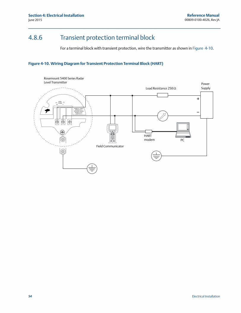
Reference Manual00809-0100-4026, Rev JA
Section 4: Electrical InstallationJune 2015
4.8.6 Transient protection terminal block
For a terminal block with transient protection, wire the transmitter as shown in Figure 4-10.
Figure 4-10. Wiring Diagram for Transient Protection Terminal Block (HART)
Rosemount 5400 Series Radar Level Transmitter
Field Communicator
Load Resistance 250
HARTmodem PC
PowerSupply
54 Electrical Installation
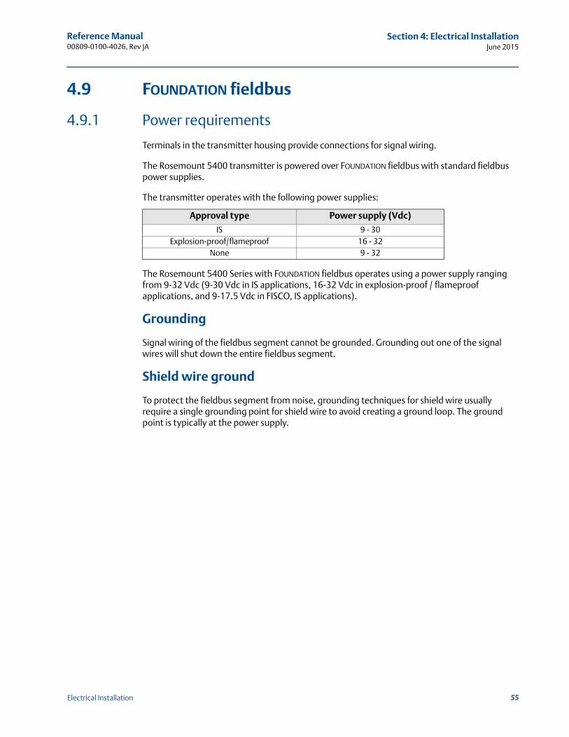
Reference Manual 00809-0100-4026, Rev JA
Section 4: Electrical InstallationJune 2015
4.9 FOUNDATION fieldbus
4.9.1 Power requirements
Terminals in the transmitter housing provide connections for signal wiring.
The Rosemount 5400 transmitter is powered over FOUNDATION fieldbus with standard fieldbus power supplies.
The transmitter operates with the following power supplies:
The Rosemount 5400 Series with FOUNDATION fieldbus operates using a power supply ranging from 9-32 Vdc (9-30 Vdc in IS applications, 16-32 Vdc in explosion-proof / flameproof applications, and 9-17.5 Vdc in FISCO, IS applications).
Grounding
Signal wiring of the fieldbus segment cannot be grounded. Grounding out one of the signal wires will shut down the entire fieldbus segment.
Shield wire ground
To protect the fieldbus segment from noise, grounding techniques for shield wire usually require a single grounding point for shield wire to avoid creating a ground loop. The ground point is typically at the power supply.
Approval type Power supply (Vdc)
IS 9 - 30Explosion-proof/flameproof 16 - 32
None 9 - 32
55Electrical Installation
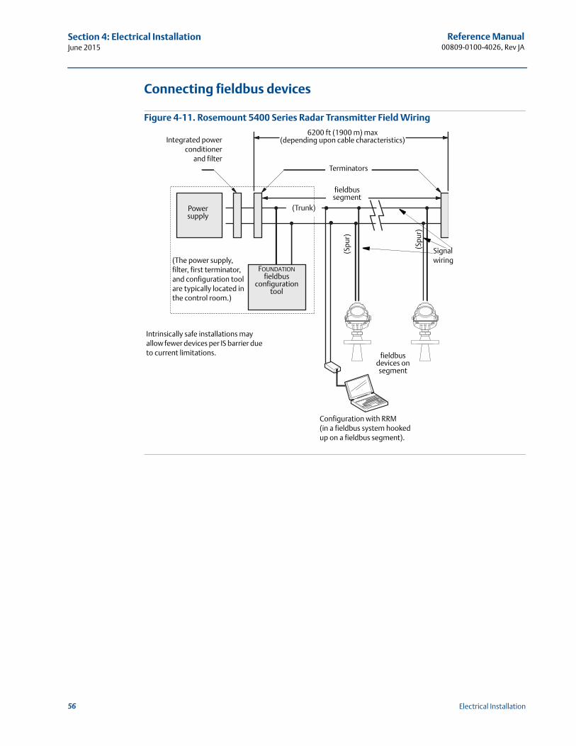
Reference Manual00809-0100-4026, Rev JA
Section 4: Electrical InstallationJune 2015
Connecting fieldbus devices
Figure 4-11. Rosemount 5400 Series Radar Transmitter Field Wiring
Signal wiring
Power supply
FOUNDATION fieldbus
configuration tool
Terminators
6200 ft (1900 m) max(depending upon cable characteristics)Integrated power
conditionerand filter
(Trunk)
(Spu
r)
(Spu
r)
(The power supply, filter, first terminator, and configuration tool are typically located in the control room.)
fieldbus segment
fieldbus devices on segment
Intrinsically safe installations may allow fewer devices per IS barrier due to current limitations.
Configuration with RRM(in a fieldbus system hooked up on a fieldbus segment).
56 Electrical Installation
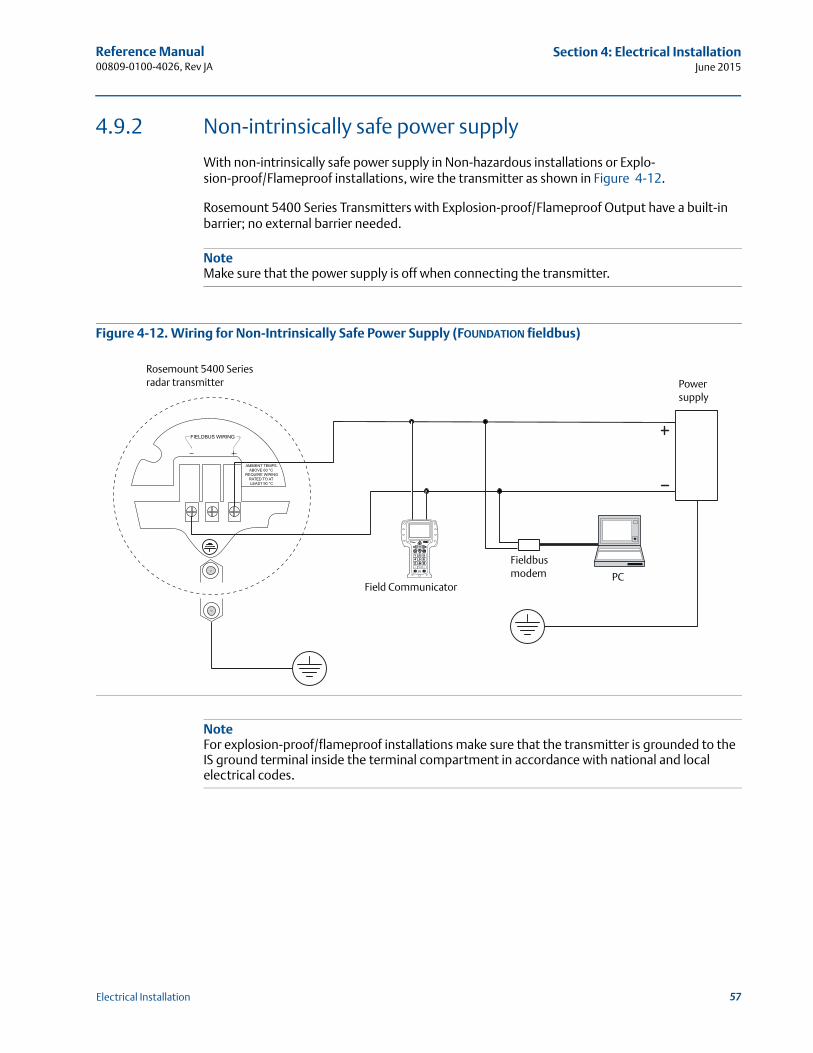
Reference Manual 00809-0100-4026, Rev JA
Section 4: Electrical InstallationJune 2015
4.9.2 Non-intrinsically safe power supply
With non-intrinsically safe power supply in Non-hazardous installations or Explo-sion-proof/Flameproof installations, wire the transmitter as shown in Figure 4-12.
Rosemount 5400 Series Transmitters with Explosion-proof/Flameproof Output have a built-in barrier; no external barrier needed.
NoteMake sure that the power supply is off when connecting the transmitter.
Figure 4-12. Wiring for Non-Intrinsically Safe Power Supply (FOUNDATION fieldbus)
NoteFor explosion-proof/flameproof installations make sure that the transmitter is grounded to the IS ground terminal inside the terminal compartment in accordance with national and local electrical codes.
Rosemount 5400 Series radar transmitter
Field Communicator
Fieldbus modem PC
Power supply
57Electrical Installation
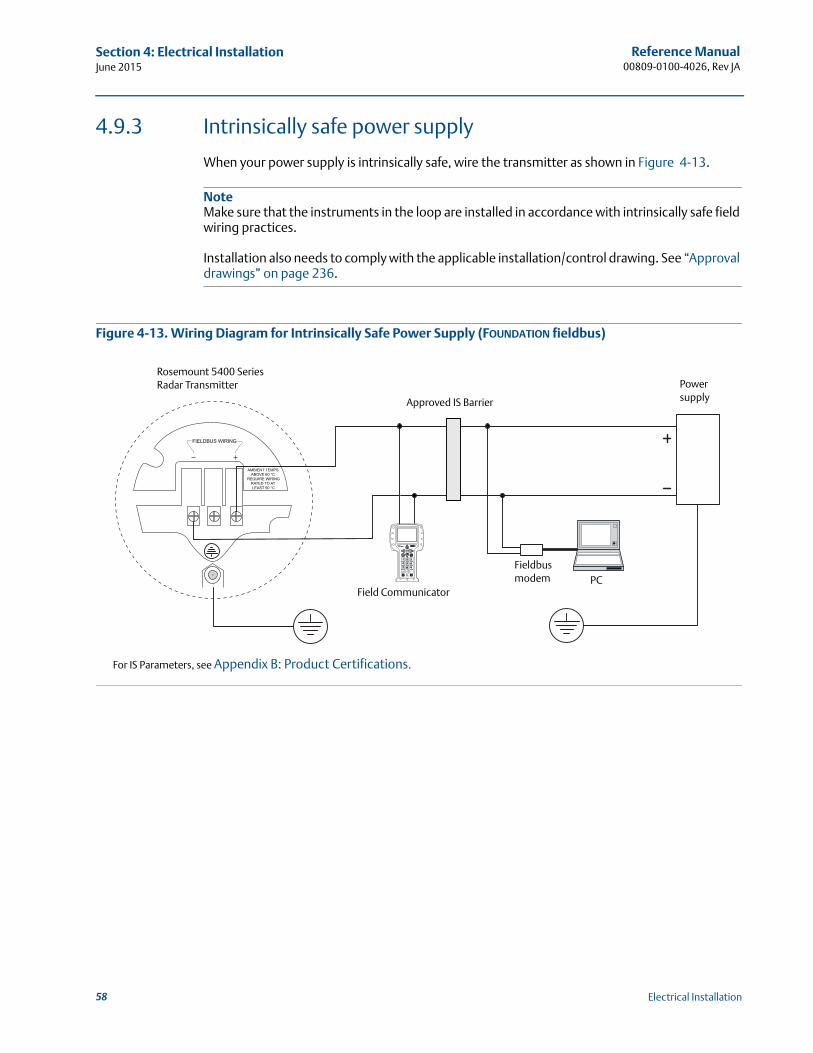
Reference Manual00809-0100-4026, Rev JA
Section 4: Electrical InstallationJune 2015
4.9.3 Intrinsically safe power supply
When your power supply is intrinsically safe, wire the transmitter as shown in Figure 4-13.
NoteMake sure that the instruments in the loop are installed in accordance with intrinsically safe field wiring practices.
Installation also needs to comply with the applicable installation/control drawing. See “Approval drawings” on page 236.
Figure 4-13. Wiring Diagram for Intrinsically Safe Power Supply (FOUNDATION fieldbus)
Rosemount 5400 Series Radar Transmitter
For IS Parameters, see Appendix B: Product Certifications.
Approved IS Barrier
Field Communicator
Fieldbus modem PC
Power supply
58 Electrical Installation
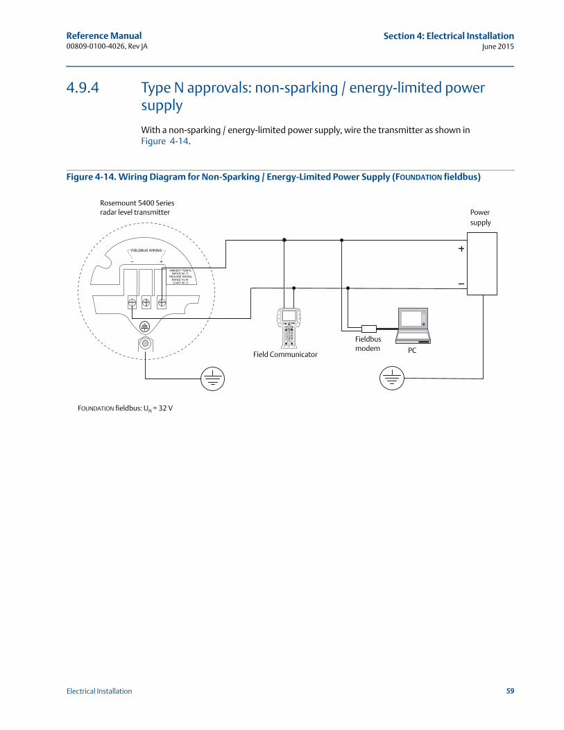
Reference Manual 00809-0100-4026, Rev JA
Section 4: Electrical InstallationJune 2015
4.9.4 Type N approvals: non-sparking / energy-limited power supply
With a non-sparking / energy-limited power supply, wire the transmitter as shown in Figure 4-14.
Figure 4-14. Wiring Diagram for Non-Sparking / Energy-Limited Power Supply (FOUNDATION fieldbus)
Rosemount 5400 Series radar level transmitter
FOUNDATION fieldbus: Un = 32 V
Powersupply
PCField Communicator
Fieldbusmodem
59Electrical Installation
Reference Manual00809-0100-4026, Rev JA
Section 4: Electrical InstallationJune 2015
4.10 HART to Modbus Converter (HMC)
The Rosemount 5400 Series RS-485 with Modbus communication transmitter version operates using a power supply ranging from 8-30 Vdc (max. rating). See the Rosemount 5300/5400 Series with HART to Modbus Converter Manual Supplement (Document No. 00809-0500-4530) for details.
Power consumption:
< 0.5 W (with HART address = 1)< 1.2 W (incl. four HART slaves)
4.10.1 Connecting the transmitter
1. Disconnect/shut off the electrical power to transmitter head and then open the instrument cover. Do not remove the cover in an explosive atmosphere with a live circuit.
2. Pull the cable through the cable gland/conduit. For the RS-485 bus, use shielded twisted pair wiring, preferably with an impedance of 120 (typically 24 AWG) in order to comply with the EIA-485 standard and EMC regulations. The maximum cable length is 4000 ft (1200 m).
3. Make sure that the transmitter housing is grounded, then connect wires according to Figure 4-15 and Table 4-2. Connect the lead that originates from the “A” line from the RS-485 bus to the terminal marked MB, and the lead that originates from the “B” line to the terminal marked MA.
4. If it is the last transmitter on the bus, connect the 120 termination resistor.
5. Connect the leads from the positive side of the power supply to the terminal marked POWER +, and the leads from the negative side of the power supply to the terminal marked POWER -. The power supply cables must be suitable for the supply voltage and ambient temperature, and approved for use in hazardous areas, where applicable.
6. Attach and tighten the housing cover. Tighten the cable gland, then plug and seal any unused terminals, and connect the power supply.
NoteRosemount 5400 Series transmitters with flameproof/explosion-proof output have a built-in barrier; no external barrier needed.
60 Electrical Installation
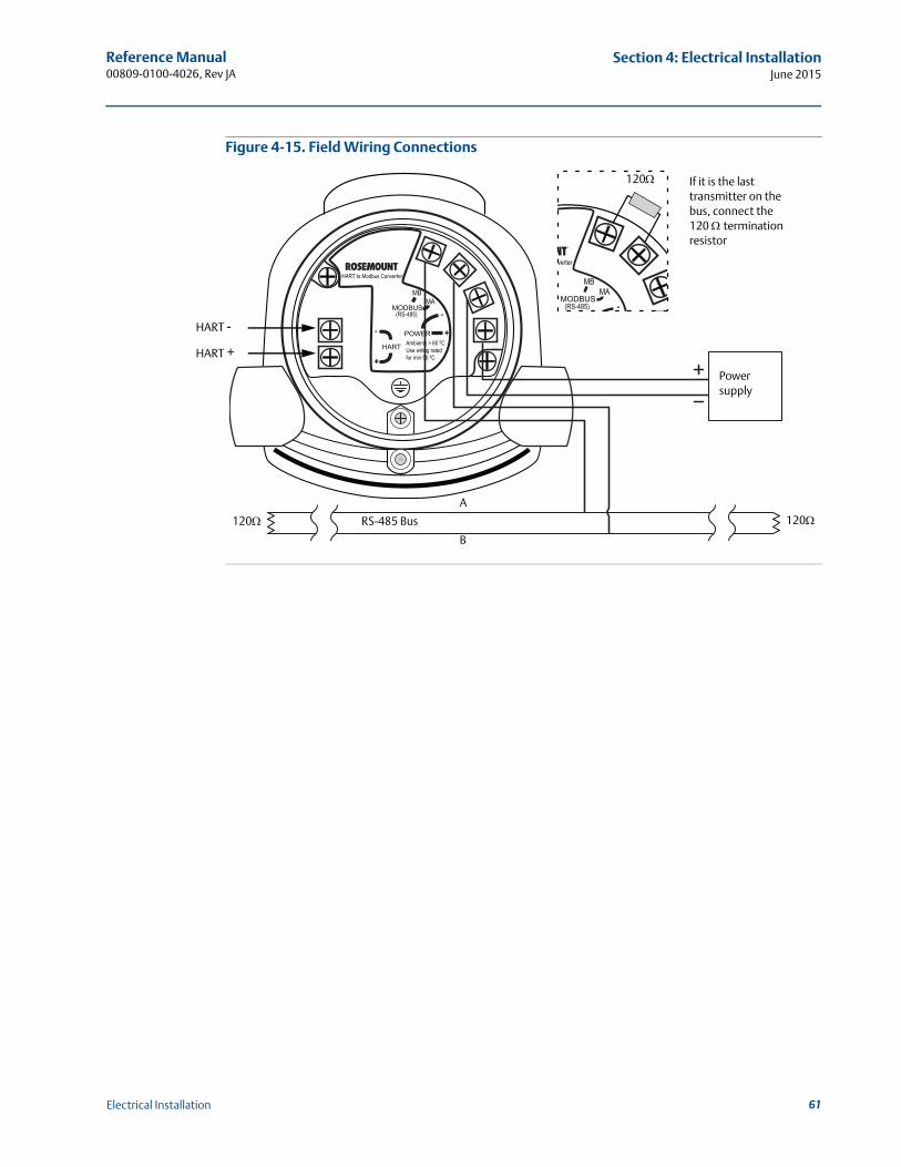
Reference Manual 00809-0100-4026, Rev JA
Section 4: Electrical InstallationJune 2015
Figure 4-15. Field Wiring Connections
MODBUS
POWER
HART
(RS-485)
HART to Modbus Converter
MBMA
-
- +
+
Ambients > 60 ºCUse wiring ratedfor min 90 ºC
RS-485 Bus
B
A
Power supply
HART +
HART -
120120
If it is the last transmitter on the bus, connect the 120 termination resistor
MODBUS(RS-485)
verter
MBMA
-
120
61Electrical Installation
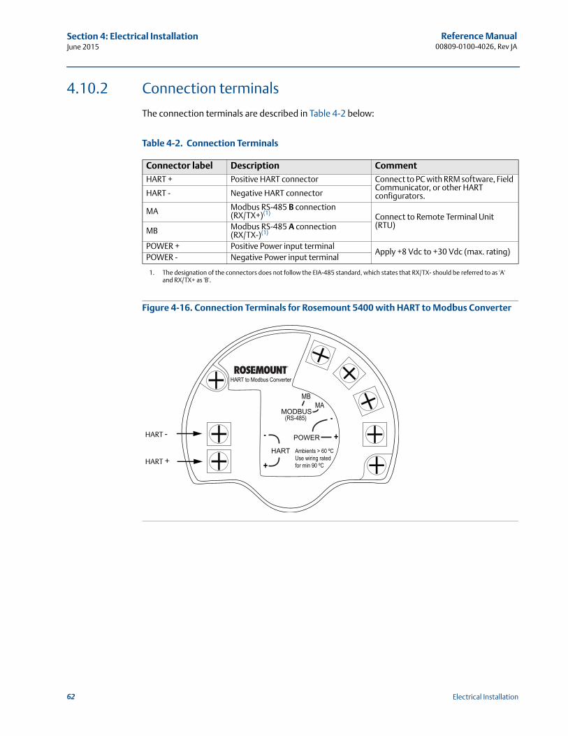
Reference Manual00809-0100-4026, Rev JA
Section 4: Electrical InstallationJune 2015
4.10.2 Connection terminals
The connection terminals are described in Table 4-2 below:
Table 4-2. Connection Terminals
Figure 4-16. Connection Terminals for Rosemount 5400 with HART to Modbus Converter
Connector label Description CommentHART + Positive HART connector Connect to PC with RRM software, Field
Communicator, or other HART configurators.HART - Negative HART connector
MA Modbus RS-485 B connection (RX/TX+)(1)
1. The designation of the connectors does not follow the EIA-485 standard, which states that RX/TX- should be referred to as 'A' and RX/TX+ as 'B'.
Connect to Remote Terminal Unit (RTU)
MB Modbus RS-485 A connection (RX/TX-)(1)
POWER + Positive Power input terminalApply +8 Vdc to +30 Vdc (max. rating)
POWER - Negative Power input terminal
MODBUS
POWER
HART
(RS-485)
HART to Modbus Converter
MBMA
Ambients > 60 ºCUse wiring ratedfor min 90 ºC
-
- +
+HART +
HART -
62 Electrical Installation
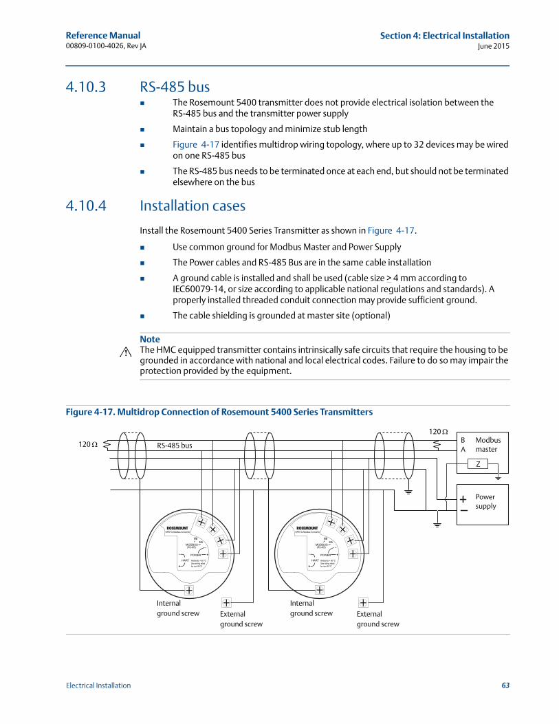
Reference Manual 00809-0100-4026, Rev JA
Section 4: Electrical InstallationJune 2015
4.10.3 RS-485 bus The Rosemount 5400 transmitter does not provide electrical isolation between the
RS-485 bus and the transmitter power supply
Maintain a bus topology and minimize stub length
Figure 4-17 identifies multidrop wiring topology, where up to 32 devices may be wired on one RS-485 bus
The RS-485 bus needs to be terminated once at each end, but should not be terminated elsewhere on the bus
4.10.4 Installation cases
Install the Rosemount 5400 Series Transmitter as shown in Figure 4-17.
Use common ground for Modbus Master and Power Supply
The Power cables and RS-485 Bus are in the same cable installation
A ground cable is installed and shall be used (cable size > 4 mm according to IEC60079-14, or size according to applicable national regulations and standards). A properly installed threaded conduit connection may provide sufficient ground.
The cable shielding is grounded at master site (optional)
NoteThe HMC equipped transmitter contains intrinsically safe circuits that require the housing to be grounded in accordance with national and local electrical codes. Failure to do so may impair the protection provided by the equipment.
Figure 4-17. Multidrop Connection of Rosemount 5400 Series Transmitters
MODBUS
POWER
HART
(RS-485)
HART to Modbus Converter
MBMA
-
- +
+
MODBUS
POWER
HART
(RS-485)
HART to Modbus Converter
MBMA
-
- +
+Ambients > 60 ºCUse wiring ratedfor min 90 ºC
Ambients > 60 ºCUse wiring ratedfor min 90 ºC
Power supply
120
120 RS-485 busBA
Modbus master
Z
Externalground screw
Internalground screw External
ground screw
Internalground screw
63Electrical Installation
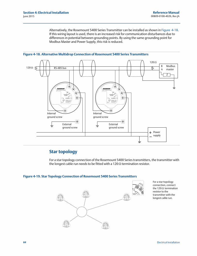
Reference Manual00809-0100-4026, Rev JA
Section 4: Electrical InstallationJune 2015
Alternatively, the Rosemount 5400 Series Transmitter can be installed as shown in Figure 4-18. If this wiring layout is used, there is an increased risk for communication disturbances due to differences in potential between grounding points. By using the same grounding point for Modbus Master and Power Supply, this risk is reduced.
Figure 4-18. Alternative Multidrop Connection of Rosemount 5400 Series Transmitters
Star topology
For a star topology connection of the Rosemount 5400 Series transmitters, the transmitter with the longest cable run needs to be fitted with a 120 termination resistor.
Figure 4-19. Star Topology Connection of Rosemount 5400 Series Transmitters
MODBUS
POWER
HART
(RS-485)
HART to Modbus Converter
MBMA
-
- +
+
MODBUS
POWER
HART
(RS-485)
HART to Modbus Converter
MBMA
-
- +
+Ambients > 60 ºCUse wiring ratedfor min 90 ºC
Ambients > 60 ºCUse wiring ratedfor min 90 ºC
Power supply
120
120 RS-485 busBA
Modbus master
Z
External ground screw
External ground screw
Internalground screw
Internalground screw
MODBUS
POWER
HART
(RS-485)
HART to Modbus Converter
MBMA
-
- +
+
MODBUS
POWER
HART
(RS-485)
HART to Modbus Converter
MBMA
-
- +
+
MODBUS
POWER
HART
(RS-485)
HART to Modbus Converter
MBMA
-
- +
+
MODBUS
POWER
HART
(RS-485)
HART to Modbus Converter
MBMA
-
- +
+
MODBUS
POWER
HART
(RS-485)
HART to Modbus Converter
MBMA
-
- +
+
MODBUS(RS-485)
verter
MBMA
-
Ambients > 60 ºCUse wiring ratedfor min 90 ºC
Ambients > 60 ºCUse wiring ratedfor min 90 ºC
Ambients > 60 ºCUse wiring ratedfor min 90 ºC
Ambients > 60 ºCUse wiring ratedfor min 90 ºC
Ambients > 60 ºCUse wiring ratedfor min 90 ºC
For a star topology connection, connect the 120 termination resistor to the transmitter with the longest cable run.
64 Electrical Installation
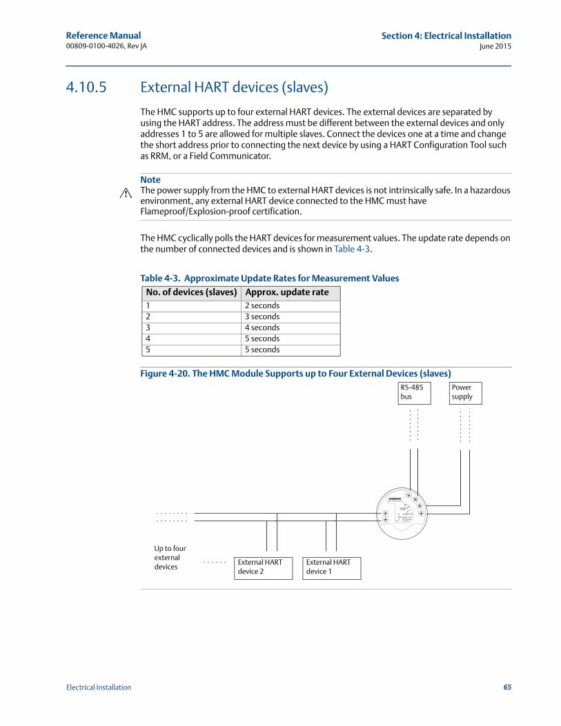
Reference Manual 00809-0100-4026, Rev JA
Section 4: Electrical InstallationJune 2015
4.10.5 External HART devices (slaves)
The HMC supports up to four external HART devices. The external devices are separated by using the HART address. The address must be different between the external devices and only addresses 1 to 5 are allowed for multiple slaves. Connect the devices one at a time and change the short address prior to connecting the next device by using a HART Configuration Tool such as RRM, or a Field Communicator.
NoteThe power supply from the HMC to external HART devices is not intrinsically safe. In a hazardous environment, any external HART device connected to the HMC must have Flameproof/Explosion-proof certification.
The HMC cyclically polls the HART devices for measurement values. The update rate depends on the number of connected devices and is shown in Table 4-3.
Table 4-3. Approximate Update Rates for Measurement Values
Figure 4-20. The HMC Module Supports up to Four External Devices (slaves)
No. of devices (slaves) Approx. update rate1 2 seconds2 3 seconds3 4 seconds4 5 seconds5 5 seconds
MODBUS
POWER
HART
(RS-485)
HART to Modbus Converter
MBMA
-
- +
+Ambients > 60 ºCUse wiring ratedfor min 90 ºC
Power supply
RS-485 bus
Up to four external devices
External HART device 2
External HART device 1
65Electrical Installation
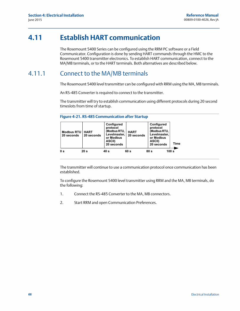
Reference Manual00809-0100-4026, Rev JA
Section 4: Electrical InstallationJune 2015
4.11 Establish HART communication
The Rosemount 5400 Series can be configured using the RRM PC software or a Field Communicator. Configuration is done by sending HART commands through the HMC to the Rosemount 5400 transmitter electronics. To establish HART communication, connect to the MA/MB terminals, or to the HART terminals. Both alternatives are described below.
4.11.1 Connect to the MA/MB terminals
The Rosemount 5400 level transmitter can be configured with RRM using the MA, MB terminals.
An RS-485 Converter is required to connect to the transmitter.
The transmitter will try to establish communication using different protocols during 20 second timeslots from time of startup.
Figure 4-21. RS-485 Communication after Startup
The transmitter will continue to use a communication protocol once communication has been established.
To configure the Rosemount 5400 level transmitter using RRM and the MA, MB terminals, do the following:
1. Connect the RS-485 Converter to the MA, MB connectors.
2. Start RRM and open Communication Preferences.
HART20 seconds
Modbus RTU20 seconds
Configured protocol (Modbus RTU, Levelmaster, or Modbus ASCII)20 seconds
HART20 seconds
Time
0 s 20 s 40 s 60 s 80 s 100 s
Configured protocol (Modbus RTU, Levelmaster, or Modbus ASCII)20 seconds
66 Electrical Installation
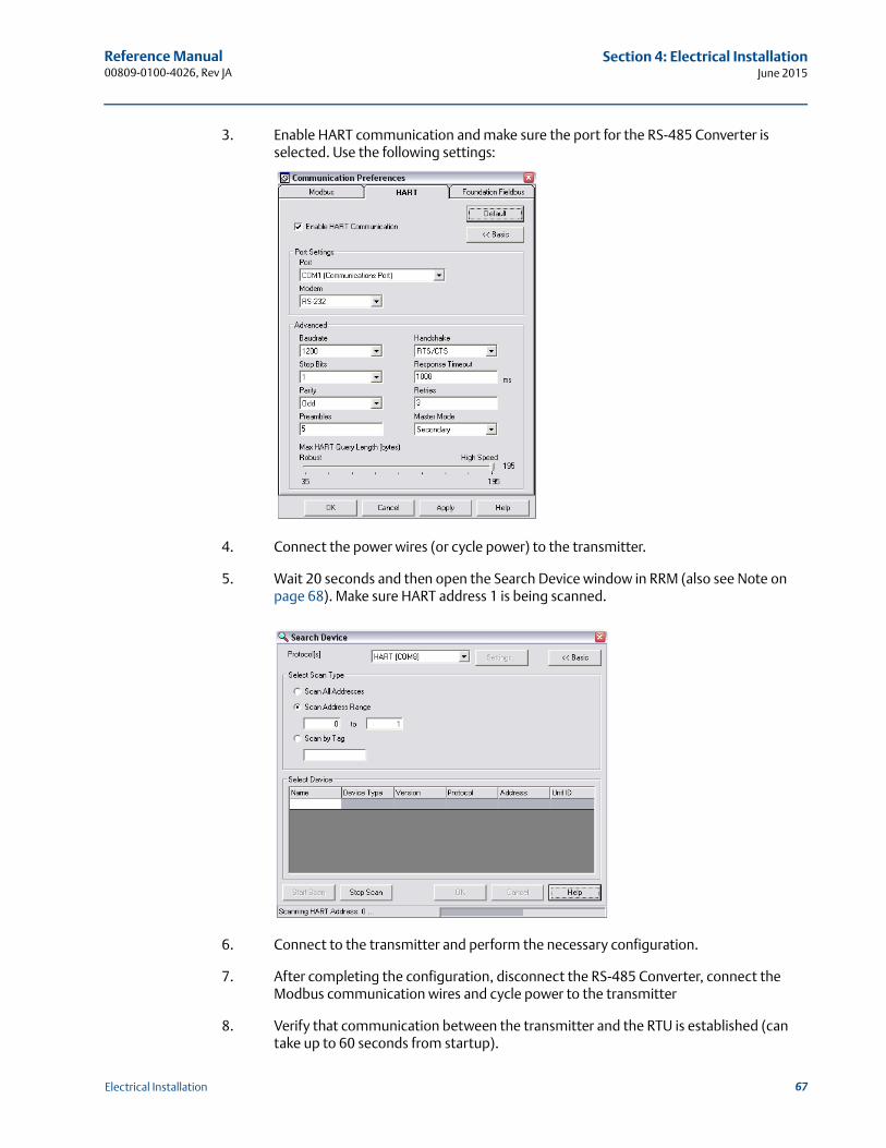
Reference Manual 00809-0100-4026, Rev JA
Section 4: Electrical InstallationJune 2015
3. Enable HART communication and make sure the port for the RS-485 Converter is selected. Use the following settings:
4. Connect the power wires (or cycle power) to the transmitter.
5. Wait 20 seconds and then open the Search Device window in RRM (also see Note on page 68). Make sure HART address 1 is being scanned.
6. Connect to the transmitter and perform the necessary configuration.
7. After completing the configuration, disconnect the RS-485 Converter, connect the Modbus communication wires and cycle power to the transmitter
8. Verify that communication between the transmitter and the RTU is established (can take up to 60 seconds from startup).
67Electrical Installation
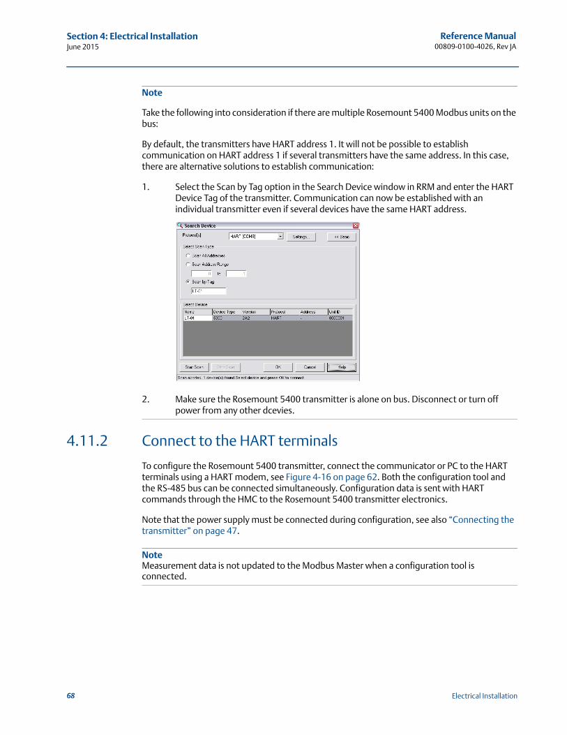
Reference Manual00809-0100-4026, Rev JA
Section 4: Electrical InstallationJune 2015
Note
Take the following into consideration if there are multiple Rosemount 5400 Modbus units on the bus:
By default, the transmitters have HART address 1. It will not be possible to establish communication on HART address 1 if several transmitters have the same address. In this case, there are alternative solutions to establish communication:
1. Select the Scan by Tag option in the Search Device window in RRM and enter the HART Device Tag of the transmitter. Communication can now be established with an individual transmitter even if several devices have the same HART address.
2. Make sure the Rosemount 5400 transmitter is alone on bus. Disconnect or turn off power from any other dcevies.
4.11.2 Connect to the HART terminals
To configure the Rosemount 5400 transmitter, connect the communicator or PC to the HART terminals using a HART modem, see Figure 4-16 on page 62. Both the configuration tool and the RS-485 bus can be connected simultaneously. Configuration data is sent with HART commands through the HMC to the Rosemount 5400 transmitter electronics.
Note that the power supply must be connected during configuration, see also “Connecting the transmitter” on page 47.
NoteMeasurement data is not updated to the Modbus Master when a configuration tool is connected.
68 Electrical Installation
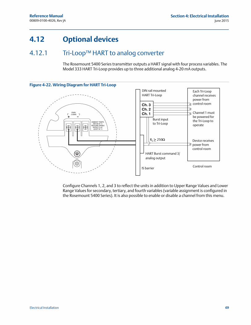
Reference Manual 00809-0100-4026, Rev JA
Section 4: Electrical InstallationJune 2015
4.12 Optional devices
4.12.1 Tri-Loop™ HART to analog converter
The Rosemount 5400 Series transmitter outputs a HART signal with four process variables. The Model 333 HART Tri-Loop provides up to three additional analog 4-20 mA outputs.
Figure 4-22. Wiring Diagram for HART Tri-Loop
Configure Channels 1, 2, and 3 to reflect the units in addition to Upper Range Values and Lower Range Values for secondary, tertiary, and fourth variables (variable assignment is configured in the Rosemount 5400 Series). It is also possible to enable or disable a channel from this menu.
Ch. 3Ch. 2Ch. 1
Each Tri-Loop channel receives power from control room
Channel 1 must be powered for the Tri-Loop to operate
Device receives power from control room
RL 250
HART Burst command 3/analog output
IS barrier
DIN rail mountedHART Tri-Loop
Control room
Burst input to Tri-Loop
69Electrical Installation
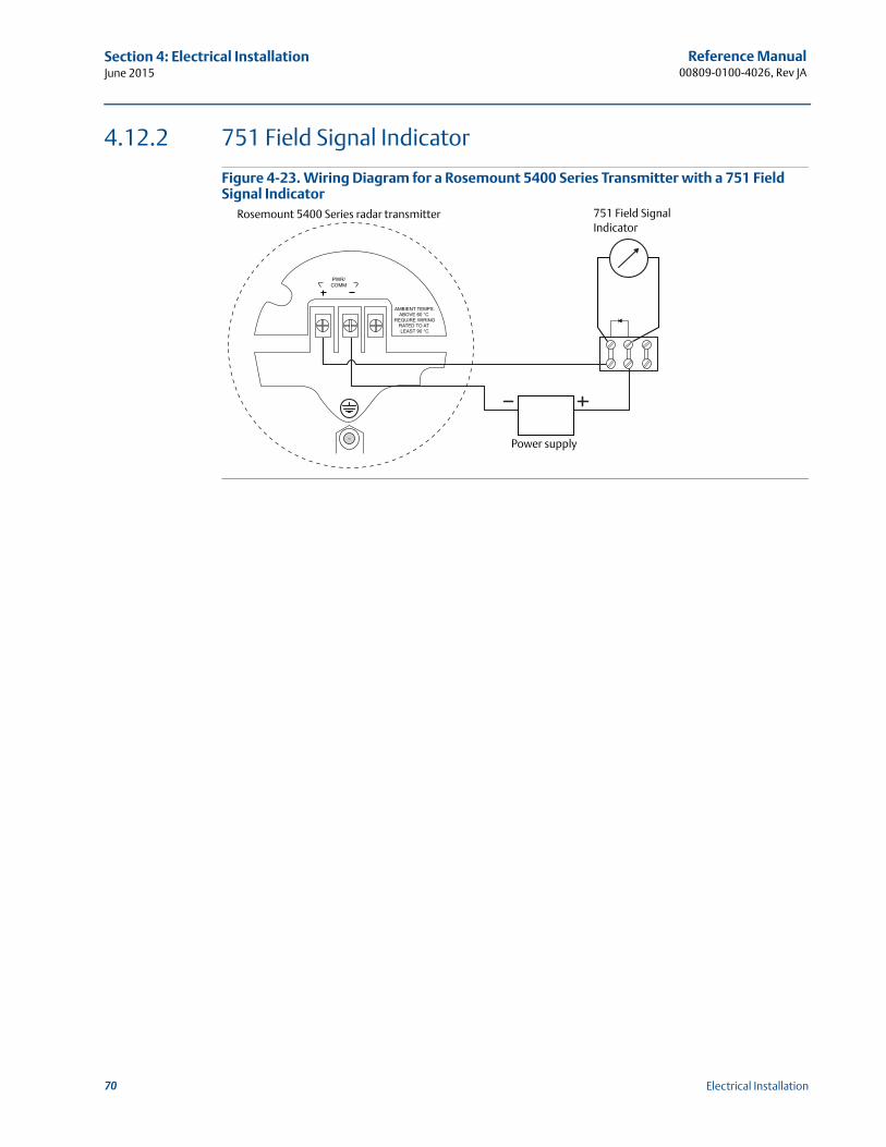
Reference Manual00809-0100-4026, Rev JA
Section 4: Electrical InstallationJune 2015
4.12.2 751 Field Signal Indicator
Figure 4-23. Wiring Diagram for a Rosemount 5400 Series Transmitter with a 751 Field Signal Indicator
Power supply
Rosemount 5400 Series radar transmitter 751 Field Signal Indicator
70 Electrical Installation
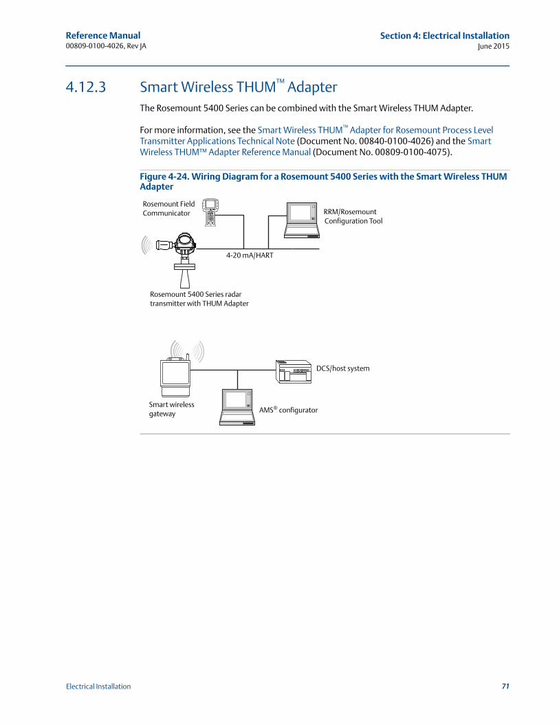
Reference Manual 00809-0100-4026, Rev JA
Section 4: Electrical InstallationJune 2015
4.12.3 Smart Wireless THUM™ AdapterThe Rosemount 5400 Series can be combined with the Smart Wireless THUM Adapter.
For more information, see the Smart Wireless THUM™ Adapter for Rosemount Process Level Transmitter Applications Technical Note (Document No. 00840-0100-4026) and the Smart Wireless THUM™ Adapter Reference Manual (Document No. 00809-0100-4075).
Figure 4-24. Wiring Diagram for a Rosemount 5400 Series with the Smart Wireless THUM Adapter
Rosemount 5400 Series radar transmitter with THUM Adapter
Rosemount Field Communicator RRM/Rosemount
Configuration Tool
4-20 mA/HART
Smart wireless gateway AMS® configurator
DCS/host system
71Electrical Installation

72
Reference Manual00809-0100-4026, Rev JA
Section 4: Electrical InstallationJune 2015
Electrical Installation
Reference Manual 00809-0100-4026, Rev JA
Section 5: Basic Configuration/Start-upJune 2015
Section 5 Basic Configuration/Start-up
Safety messages . . . . . . . . . . . . . . . . . . . . . . . . . . . . . . . . . . . . . . . . . . . . . . . . . . . . . . . . . . . . page 73Overview . . . . . . . . . . . . . . . . . . . . . . . . . . . . . . . . . . . . . . . . . . . . . . . . . . . . . . . . . . . . . . . . . . page 74Basic configuration parameters . . . . . . . . . . . . . . . . . . . . . . . . . . . . . . . . . . . . . . . . . . . . . . . page 75Basic configuration using RRM . . . . . . . . . . . . . . . . . . . . . . . . . . . . . . . . . . . . . . . . . . . . . . . . page 84Configuration using a Field Communicator . . . . . . . . . . . . . . . . . . . . . . . . . . . . . . . . . . . . . page 101Basic configuration using AMS Suite . . . . . . . . . . . . . . . . . . . . . . . . . . . . . . . . . . . . . . . . . . . page 105Configuration using DeltaV . . . . . . . . . . . . . . . . . . . . . . . . . . . . . . . . . . . . . . . . . . . . . . . . . . page 106FOUNDATION fieldbus overview . . . . . . . . . . . . . . . . . . . . . . . . . . . . . . . . . . . . . . . . . . . . . . . . page 112Application examples . . . . . . . . . . . . . . . . . . . . . . . . . . . . . . . . . . . . . . . . . . . . . . . . . . . . . . . page 115Tri-Loop™ HART to Analog Converter . . . . . . . . . . . . . . . . . . . . . . . . . . . . . . . . . . . . . . . . . . page 117HART multidrop configuration . . . . . . . . . . . . . . . . . . . . . . . . . . . . . . . . . . . . . . . . . . . . . . . . page 119
5.1 Safety messages
Procedures and instructions in this section may require special precautions to ensure the safety of the personnel performing the operations. Information that raises potential safety issues is
indicated by a warning symbol ( ). Refer to the safety messages listed at the beginning of each section before performing an operation preceded by this symbol.
Explosions could result in death or serious injury.
Verify that the operating environment of the gauge is consistent with the appropriate hazardous locations certifications.
Before connecting a Field Communicator in an explosive atmosphere, make sure the instruments in the loop are installed in accordance with intrinsically safe or non-incendive field wiring practices.
Do not remove the gauge cover in explosive atmospheres when the circuit is alive.
All connection head covers must be fully engaged to meet explosion-proof requirements.
Failure to follow safe installation and servicing guidelines could result in death or serious injury.
Make sure only qualified personnel perform the installation.
Use the equipment only as specified in this manual. Failure to do so may impair the protection provided by the equipment.
Do not perform any service other than those contained in this manual unless you are qualified.
73Basic Configuration/Start-up
Reference Manual00809-0100-4026, Rev JA
Section 5: Basic Configuration/Start-upJune 2015
5.2 Overview
The configuration of a Rosemount 5400 Series Transmitter is normally a simple and straightfor-ward task. If the transmitter is pre-configured at the factory according to ordering specifications in the Configuration Data Sheet, no further basic configuration is required, unless tank conditions have changed.
The Rosemount 5400 Series supports a set of advanced configuration options that can be used to handle special tank conditions and applications. For further information on advanced configuration options, see Appendix C: Advanced Configuration.
5.2.1 Basic configuration parameters
The basic configuration includes parameters for a standard configuration which is sufficient in most cases. The basic configuration comprises the following items:
Measurement Units
Tank Configuration- Tank Geometry- Environment- Volume
Analog Output
Echo Tuning: see page 83 for more information on the Amplitude Threshold Curve (ATC), and “Echo tuning” on page 83 for more information on False Echo Registration
5.2.2 Configuration tools
There are several tools available for basic configuration of a Rosemount 5400 Series transmitter:
RRM. Note that RRM is required for advanced configuration features. See “Basic configuration using RRM” on page 84 for information on using RRM to configure the Rosemount 5400 Series.
Rosemount Field Communicator.See “Configuration using a Field Communicator” on page 101 for the Field Communicator Menu Tree.
DTM (compliant with version 1.2 of the FDT®/DTM™ specification) is also available supporting configuration in, for instance, Yokogawa Fieldmate/PRM, E+H FieldCareTM, and PACTwareTM
AMS® Suite software (for HART®).See “Basic configuration using AMS Suite” on page 105 for information on configuring AMS Suite.
DeltaVTM (only for FOUNDATION™ fieldbus).See “Configuration using DeltaV” on page 106 for information on configuring the Rosemount 5400 Series transmitter using DeltaV.
Other tools that support EDDL functionality.
RRM is a user-friendly, Windows™ based software package that includes waveform plots, offline/online configuration Wizard, logging, and extensive online help.
74 Basic Configuration/Start-up
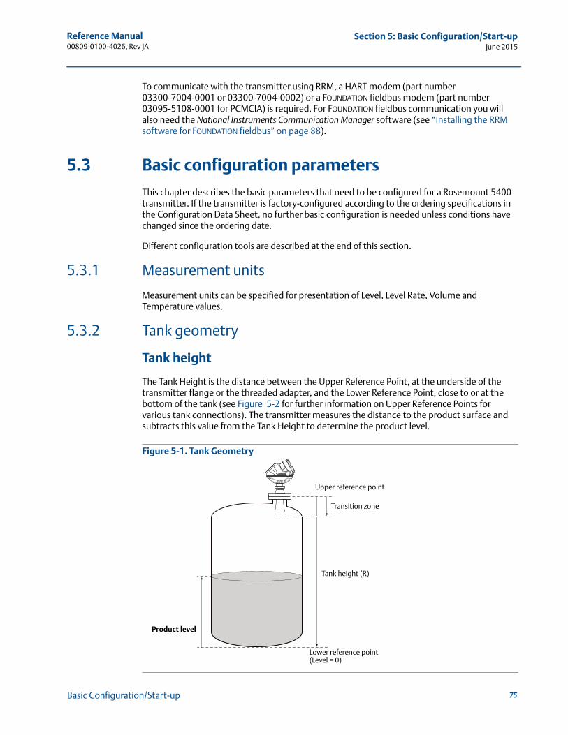
Reference Manual 00809-0100-4026, Rev JA
Section 5: Basic Configuration/Start-upJune 2015
To communicate with the transmitter using RRM, a HART modem (part number 03300-7004-0001 or 03300-7004-0002) or a FOUNDATION fieldbus modem (part number 03095-5108-0001 for PCMCIA) is required. For FOUNDATION fieldbus communication you will also need the National Instruments Communication Manager software (see “Installing the RRM software for FOUNDATION fieldbus” on page 88).
5.3 Basic configuration parameters
This chapter describes the basic parameters that need to be configured for a Rosemount 5400 transmitter. If the transmitter is factory-configured according to the ordering specifications in the Configuration Data Sheet, no further basic configuration is needed unless conditions have changed since the ordering date.
Different configuration tools are described at the end of this section.
5.3.1 Measurement units
Measurement units can be specified for presentation of Level, Level Rate, Volume and Temperature values.
5.3.2 Tank geometry
Tank height
The Tank Height is the distance between the Upper Reference Point, at the underside of the transmitter flange or the threaded adapter, and the Lower Reference Point, close to or at the bottom of the tank (see Figure 5-2 for further information on Upper Reference Points for various tank connections). The transmitter measures the distance to the product surface and subtracts this value from the Tank Height to determine the product level.
Figure 5-1. Tank Geometry
Tank height (R)
Product level
Upper reference point
Lower reference point(Level = 0)
Transition zone
75Basic Configuration/Start-up
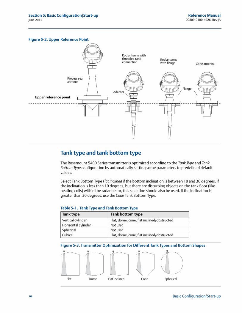
Reference Manual00809-0100-4026, Rev JA
Section 5: Basic Configuration/Start-upJune 2015
Figure 5-2. Upper Reference Point
Tank type and tank bottom type
The Rosemount 5400 Series transmitter is optimized according to the Tank Type and Tank Bottom Type configuration by automatically setting some parameters to predefined default values.
Select Tank Bottom Type Flat Inclined if the bottom inclination is between 10 and 30 degrees. If the inclination is less than 10 degrees, but there are disturbing objects on the tank floor (like heating coils) within the radar beam, this selection should also be used. If the inclination is greater than 30 degrees, use the Cone Tank Bottom Type.
Table 5-1. Tank Type and Tank Bottom Type
Figure 5-3. Transmitter Optimization for Different Tank Types and Bottom Shapes
Tank type Tank bottom type
Vertical cylinder Flat, dome, cone, flat inclined/obstructedHorizontal cylinder Not usedSpherical Not usedCubical Flat, dome, cone, flat inclined/obstructed
Cone antennaRod antenna with flange
Rod antenna with threaded tank connection
Upper reference point
AdapterFlange
Process seal antenna
Flat Dome ConeFlat inclined Spherical
76 Basic Configuration/Start-up
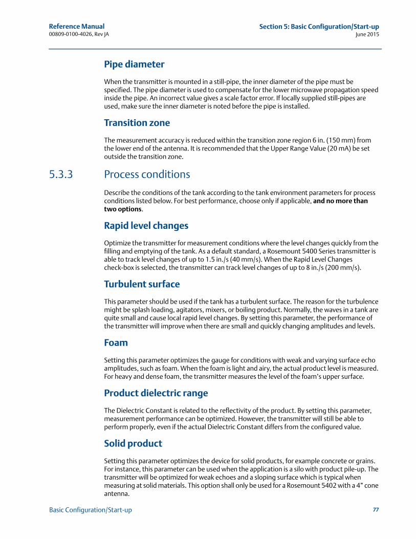
Reference Manual 00809-0100-4026, Rev JA
Section 5: Basic Configuration/Start-upJune 2015
Pipe diameter
When the transmitter is mounted in a still-pipe, the inner diameter of the pipe must be specified. The pipe diameter is used to compensate for the lower microwave propagation speed inside the pipe. An incorrect value gives a scale factor error. If locally supplied still-pipes are used, make sure the inner diameter is noted before the pipe is installed.
Transition zone
The measurement accuracy is reduced within the transition zone region 6 in. (150 mm) from the lower end of the antenna. It is recommended that the Upper Range Value (20 mA) be set outside the transition zone.
5.3.3 Process conditions
Describe the conditions of the tank according to the tank environment parameters for process conditions listed below. For best performance, choose only if applicable, and no more than two options.
Rapid level changes
Optimize the transmitter for measurement conditions where the level changes quickly from the filling and emptying of the tank. As a default standard, a Rosemount 5400 Series transmitter is able to track level changes of up to 1.5 in./s (40 mm/s). When the Rapid Level Changes check-box is selected, the transmitter can track level changes of up to 8 in./s (200 mm/s).
Turbulent surface
This parameter should be used if the tank has a turbulent surface. The reason for the turbulence might be splash loading, agitators, mixers, or boiling product. Normally, the waves in a tank are quite small and cause local rapid level changes. By setting this parameter, the performance of the transmitter will improve when there are small and quickly changing amplitudes and levels.
Foam
Setting this parameter optimizes the gauge for conditions with weak and varying surface echo amplitudes, such as foam. When the foam is light and airy, the actual product level is measured. For heavy and dense foam, the transmitter measures the level of the foam’s upper surface.
Product dielectric range
The Dielectric Constant is related to the reflectivity of the product. By setting this parameter, measurement performance can be optimized. However, the transmitter will still be able to perform properly, even if the actual Dielectric Constant differs from the configured value.
Solid product
Setting this parameter optimizes the device for solid products, for example concrete or grains. For instance, this parameter can be used when the application is a silo with product pile-up. The transmitter will be optimized for weak echoes and a sloping surface which is typical when measuring at solid materials. This option shall only be used for a Rosemount 5402 with a 4” cone antenna.
77Basic Configuration/Start-up
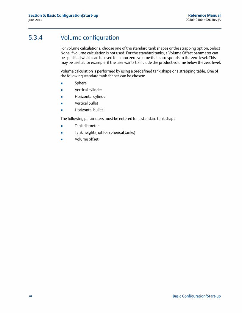
Reference Manual00809-0100-4026, Rev JA
Section 5: Basic Configuration/Start-upJune 2015
5.3.4 Volume configuration
For volume calculations, choose one of the standard tank shapes or the strapping option. Select None if volume calculation is not used. For the standard tanks, a Volume Offset parameter can be specified which can be used for a non-zero volume that corresponds to the zero level. This may be useful, for example, if the user wants to include the product volume below the zero level.
Volume calculation is performed by using a predefined tank shape or a strapping table. One of the following standard tank shapes can be chosen:
Sphere
Vertical cylinder
Horizontal cylinder
Vertical bullet
Horizontal bullet
The following parameters must be entered for a standard tank shape:
Tank diameter
Tank height (not for spherical tanks)
Volume offset
78 Basic Configuration/Start-up
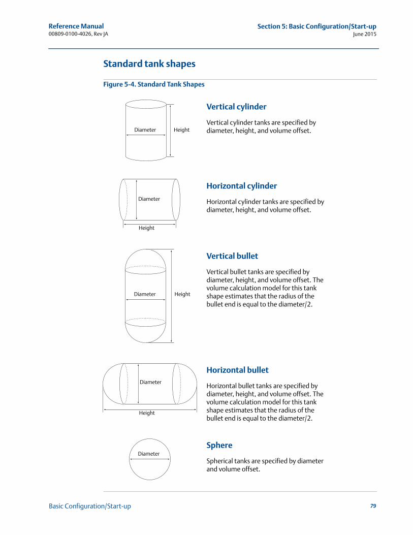
Reference Manual 00809-0100-4026, Rev JA
Section 5: Basic Configuration/Start-upJune 2015
Standard tank shapes
Figure 5-4. Standard Tank Shapes
Vertical cylinder
Vertical cylinder tanks are specified by diameter, height, and volume offset.
Horizontal cylinder
Horizontal cylinder tanks are specified by diameter, height, and volume offset.
Vertical bullet
Vertical bullet tanks are specified by diameter, height, and volume offset. The volume calculation model for this tank shape estimates that the radius of the bullet end is equal to the diameter/2.
Horizontal bullet
Horizontal bullet tanks are specified by diameter, height, and volume offset. The volume calculation model for this tank shape estimates that the radius of the bullet end is equal to the diameter/2.
Sphere
Spherical tanks are specified by diameter and volume offset.
Diameter Height
Diameter
Height
Diameter Height
Diameter
Height
Diameter
79Basic Configuration/Start-up
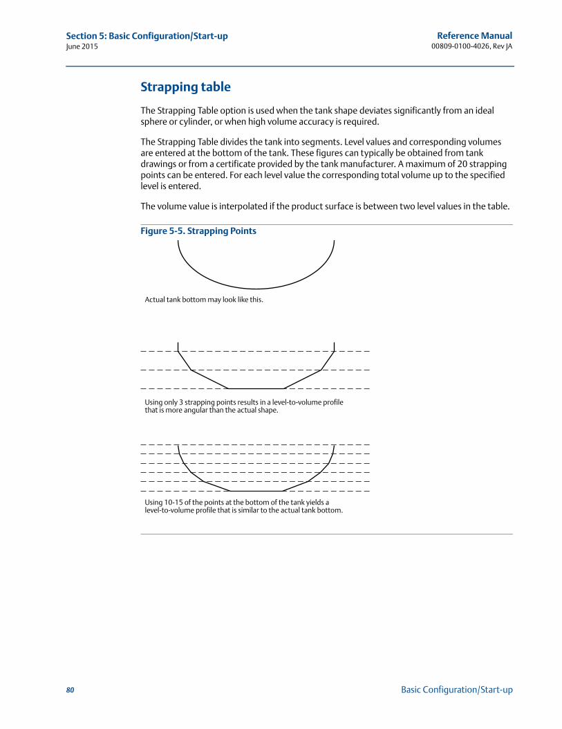
Reference Manual00809-0100-4026, Rev JA
Section 5: Basic Configuration/Start-upJune 2015
Strapping table
The Strapping Table option is used when the tank shape deviates significantly from an ideal sphere or cylinder, or when high volume accuracy is required.
The Strapping Table divides the tank into segments. Level values and corresponding volumes are entered at the bottom of the tank. These figures can typically be obtained from tank drawings or from a certificate provided by the tank manufacturer. A maximum of 20 strapping points can be entered. For each level value the corresponding total volume up to the specified level is entered.
The volume value is interpolated if the product surface is between two level values in the table.
Figure 5-5. Strapping Points
Actual tank bottom may look like this.
Using only 3 strapping points results in a level-to-volume profile that is more angular than the actual shape.
Using 10-15 of the points at the bottom of the tank yields a level-to-volume profile that is similar to the actual tank bottom.
80 Basic Configuration/Start-up
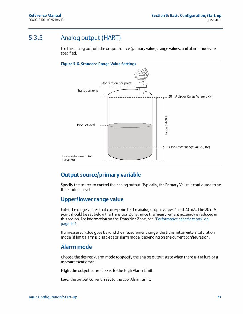
Reference Manual 00809-0100-4026, Rev JA
Section 5: Basic Configuration/Start-upJune 2015
5.3.5 Analog output (HART)
For the analog output, the output source (primary value), range values, and alarm mode are specified.
Figure 5-6. Standard Range Value Settings
Output source/primary variable
Specify the source to control the analog output. Typically, the Primary Value is configured to be the Product Level.
Upper/lower range value
Enter the range values that correspond to the analog output values 4 and 20 mA. The 20 mA point should be set below the Transition Zone, since the measurement accuracy is reduced in this region. For information on the Transition Zone, see “Performance specifications” on page 191.
If a measured value goes beyond the measurement range, the transmitter enters saturation mode (if limit alarm is disabled) or alarm mode, depending on the current configuration.
Alarm mode
Choose the desired Alarm mode to specify the analog output state when there is a failure or a measurement error.
High: the output current is set to the High Alarm Limit.
Low: the output current is set to the Low Alarm Limit.
20 mA Upper Range Value (URV)
Product level
4 mA Lower Range Value (LRV)
Rang
e 0-
100
%
Lower reference point(Level=0)
Upper reference point
Transition zone
81Basic Configuration/Start-up
Reference Manual00809-0100-4026, Rev JA
Section 5: Basic Configuration/Start-upJune 2015
Freeze Current: the output current is set to the last valid value at the time when the error occurs.
Default settings for alarm mode:
Measurement errors: Output current = High
Measured value out of range: transmitter enters saturation mode (if Limit Alarm is disabled)
Table 5-2. Analog Output: Standard Alarm Value vs. Saturation Value
In saturation mode, if the primary variable is not in low alarm mode, the minimum output is 3.9 mA. If the primary variable is not in high alarm mode, the maximum output is 20.8 mA.
Table 5-3. Analog Output: NAMUR-compliant Alarm Value vs. Saturation Value
5.3.6 Level and distance calibration
Level and distance calibration may be necessary when using a nozzle or pipe or if there are disturbances in the near zone caused by a physical object.
Non-metallic (e.g. plastic) vessels and installation geometry may introduce an offset for the zero reference point. This offset may be up to ± 25 mm. The offset can be compensated for using Distance Calibration.
When calibrating the transmitter, it is important that the product surface is calm and that the tank is not being filled or emptied.
A complete calibration is performed in two steps:
1. Calibrate the distance measurement by adjusting the Calibration Offset parameter.
2. Calibrate the level measurement by adjusting the Tank Height.
Level 4–20 mA saturation value 4–20 mA alarm value
Low 3.9 mA 3.75 mA
High 20.8 mA 21.75 mA
Level 4–20 mA saturation value 4–20 mA alarm value
High 20.5 mA 22.5 mA
82 Basic Configuration/Start-up
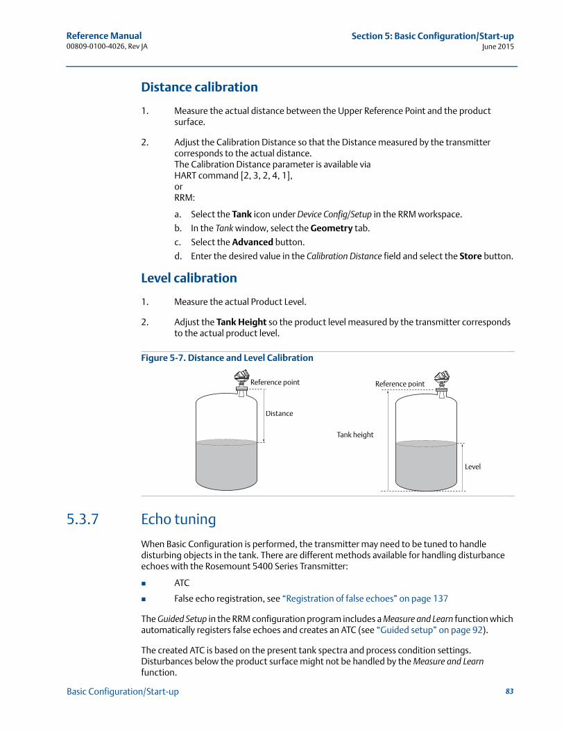
Reference Manual 00809-0100-4026, Rev JA
Section 5: Basic Configuration/Start-upJune 2015
Distance calibration
1. Measure the actual distance between the Upper Reference Point and the product surface.
2. Adjust the Calibration Distance so that the Distance measured by the transmitter corresponds to the actual distance. The Calibration Distance parameter is available via HART command [2, 3, 2, 4, 1],orRRM:
a. Select the Tank icon under Device Config/Setup in the RRM workspace.
b. In the Tank window, select the Geometry tab.
c. Select the Advanced button.
d. Enter the desired value in the Calibration Distance field and select the Store button.
Level calibration
1. Measure the actual Product Level.
2. Adjust the Tank Height so the product level measured by the transmitter corresponds to the actual product level.
Figure 5-7. Distance and Level Calibration
5.3.7 Echo tuning
When Basic Configuration is performed, the transmitter may need to be tuned to handle disturbing objects in the tank. There are different methods available for handling disturbance echoes with the Rosemount 5400 Series Transmitter:
ATC
False echo registration, see “Registration of false echoes” on page 137
The Guided Setup in the RRM configuration program includes a Measure and Learn function which automatically registers false echoes and creates an ATC (see “Guided setup” on page 92).
The created ATC is based on the present tank spectra and process condition settings. Disturbances below the product surface might not be handled by the Measure and Learn function.
Reference point
Distance
Reference point
Tank height
Level
83Basic Configuration/Start-up
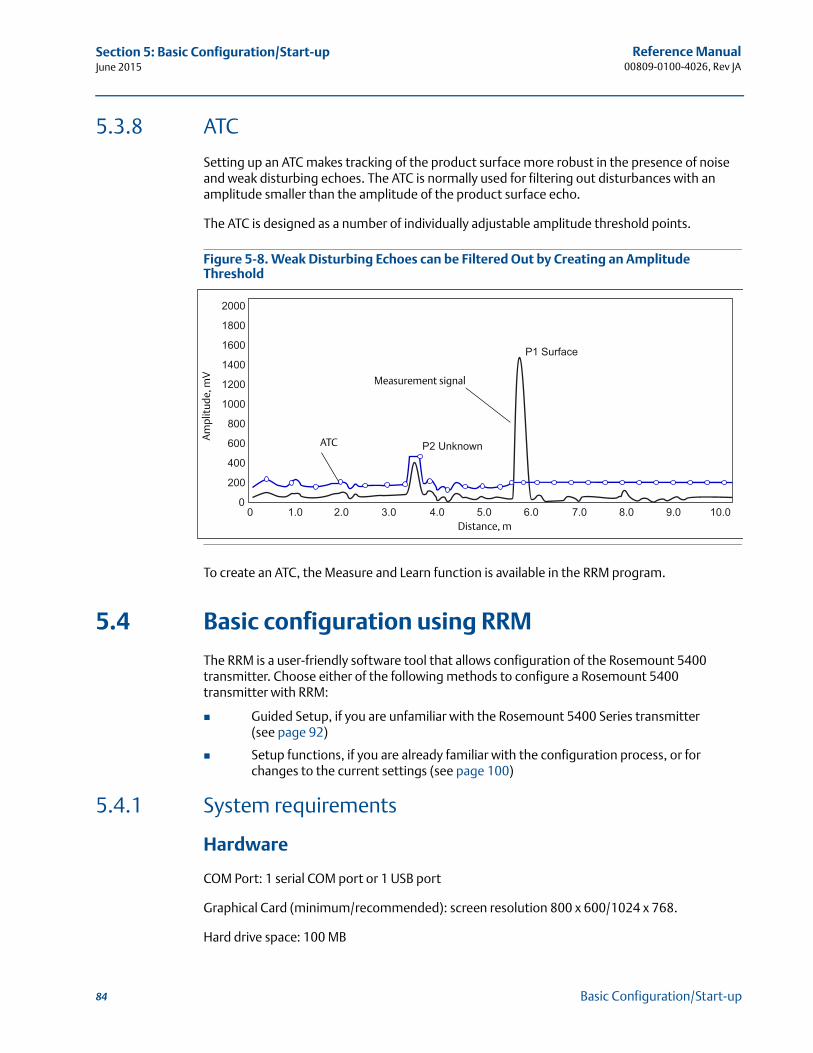
Reference Manual00809-0100-4026, Rev JA
Section 5: Basic Configuration/Start-upJune 2015
5.3.8 ATC
Setting up an ATC makes tracking of the product surface more robust in the presence of noise and weak disturbing echoes. The ATC is normally used for filtering out disturbances with an amplitude smaller than the amplitude of the product surface echo.
The ATC is designed as a number of individually adjustable amplitude threshold points.
Figure 5-8. Weak Disturbing Echoes can be Filtered Out by Creating an Amplitude Threshold
To create an ATC, the Measure and Learn function is available in the RRM program.
5.4 Basic configuration using RRM
The RRM is a user-friendly software tool that allows configuration of the Rosemount 5400 transmitter. Choose either of the following methods to configure a Rosemount 5400 transmitter with RRM:
Guided Setup, if you are unfamiliar with the Rosemount 5400 Series transmitter (see page 92)
Setup functions, if you are already familiar with the configuration process, or for changes to the current settings (see page 100)
5.4.1 System requirements
Hardware
COM Port: 1 serial COM port or 1 USB port
Graphical Card (minimum/recommended): screen resolution 800 x 600/1024 x 768.
Hard drive space: 100 MB
ATC
Measurement signal
Am
plit
ude,
mV
Distance, m
84 Basic Configuration/Start-up
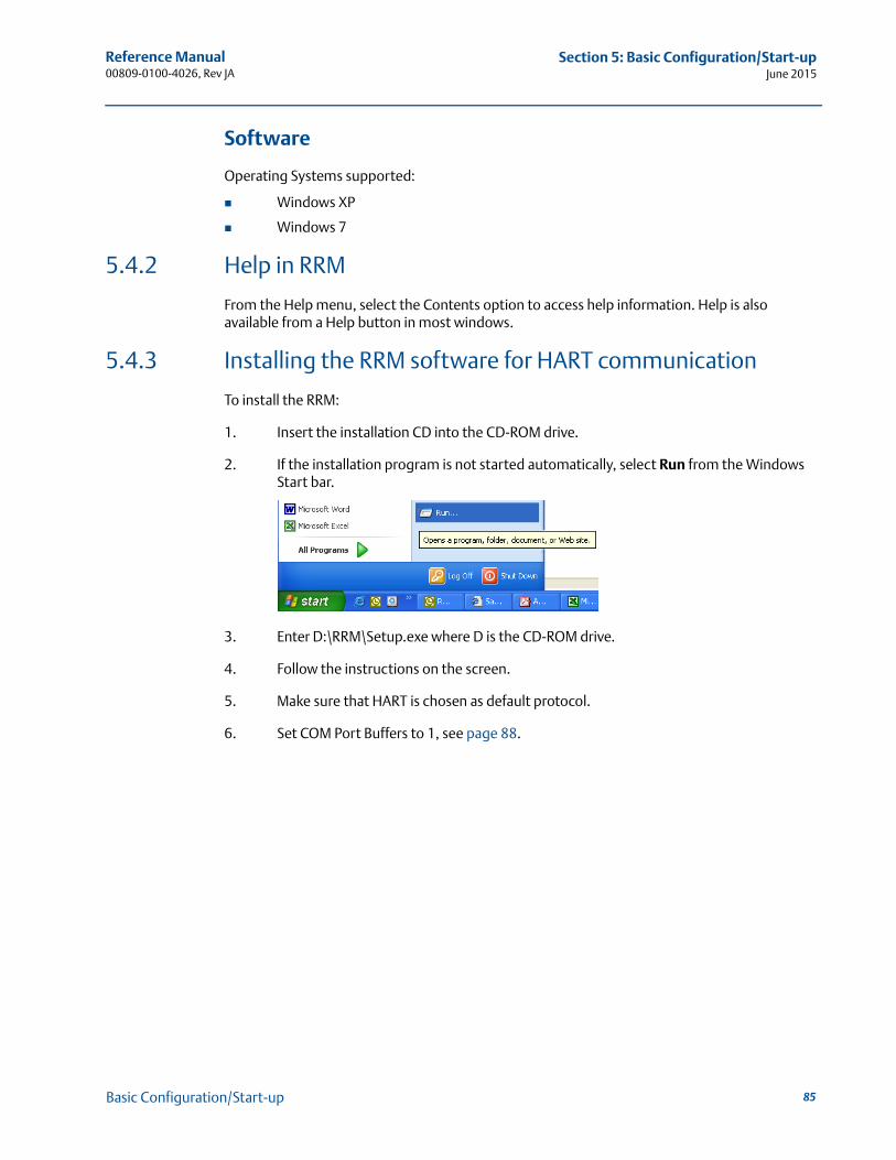
Reference Manual 00809-0100-4026, Rev JA
Section 5: Basic Configuration/Start-upJune 2015
Software
Operating Systems supported:
Windows XP
Windows 7
5.4.2 Help in RRM
From the Help menu, select the Contents option to access help information. Help is also available from a Help button in most windows.
5.4.3 Installing the RRM software for HART communication
To install the RRM:
1. Insert the installation CD into the CD-ROM drive.
2. If the installation program is not started automatically, select Run from the Windows Start bar.
3. Enter D:\RRM\Setup.exe where D is the CD-ROM drive.
4. Follow the instructions on the screen.
5. Make sure that HART is chosen as default protocol.
6. Set COM Port Buffers to 1, see page 88.
85Basic Configuration/Start-up
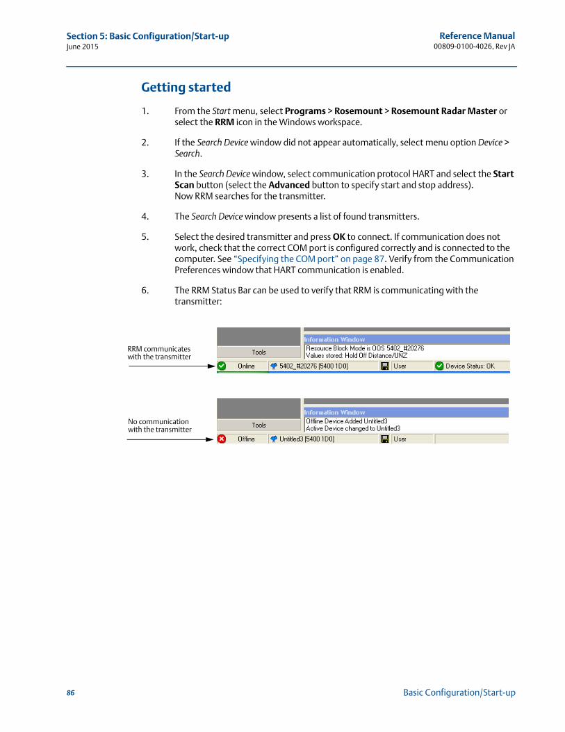
Reference Manual00809-0100-4026, Rev JA
Section 5: Basic Configuration/Start-upJune 2015
Getting started
1. From the Start menu, select Programs > Rosemount > Rosemount Radar Master or select the RRM icon in the Windows workspace.
2. If the Search Device window did not appear automatically, select menu option Device > Search.
3. In the Search Device window, select communication protocol HART and select the Start Scan button (select the Advanced button to specify start and stop address).Now RRM searches for the transmitter.
4. The Search Device window presents a list of found transmitters.
5. Select the desired transmitter and press OK to connect. If communication does not work, check that the correct COM port is configured correctly and is connected to the computer. See “Specifying the COM port” on page 87. Verify from the Communication Preferences window that HART communication is enabled.
6. The RRM Status Bar can be used to verify that RRM is communicating with the transmitter:
RRM communicates with the transmitter
No communication with the transmitter
86 Basic Configuration/Start-up
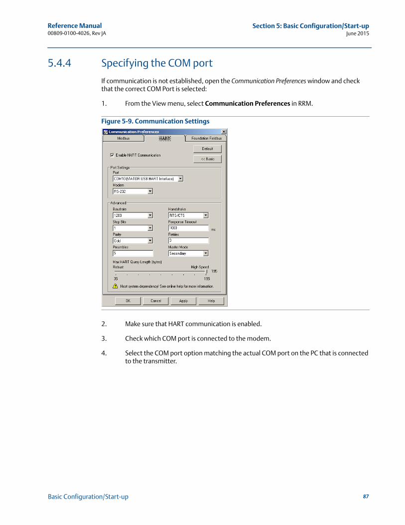
Reference Manual 00809-0100-4026, Rev JA
Section 5: Basic Configuration/Start-upJune 2015
5.4.4 Specifying the COM port
If communication is not established, open the Communication Preferences window and check that the correct COM Port is selected:
1. From the View menu, select Communication Preferences in RRM.
Figure 5-9. Communication Settings
2. Make sure that HART communication is enabled.
3. Check which COM port is connected to the modem.
4. Select the COM port option matching the actual COM port on the PC that is connected to the transmitter.
87Basic Configuration/Start-up
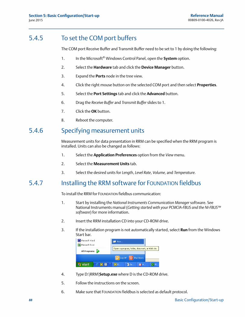
Reference Manual00809-0100-4026, Rev JA
Section 5: Basic Configuration/Start-upJune 2015
5.4.5 To set the COM port buffers
The COM port Receive Buffer and Transmit Buffer need to be set to 1 by doing the following:
1. In the Microsoft® Windows Control Panel, open the System option.
2. Select the Hardware tab and click the Device Manager button.
3. Expand the Ports node in the tree view.
4. Click the right mouse button on the selected COM port and then select Properties.
5. Select the Port Settings tab and click the Advanced button.
6. Drag the Receive Buffer and Transmit Buffer slides to 1.
7. Click the OK button.
8. Reboot the computer.
5.4.6 Specifying measurement units
Measurement units for data presentation in RRM can be specified when the RRM program is installed. Units can also be changed as follows:
1. Select the Application Preferences option from the View menu.
2. Select the Measurement Units tab.
3. Select the desired units for Length, Level Rate, Volume, and Temperature.
5.4.7 Installing the RRM software for FOUNDATION fieldbus
To install the RRM for FOUNDATION fieldbus communication:
1. Start by installing the National Instruments Communication Manager software. See National Instruments manual (Getting started with your PCMCIA-FBUS and the NI-FBUS™ software) for more information.
2. Insert the RRM installation CD into your CD-ROM drive.
3. If the installation program is not automatically started, select Run from the Windows Start bar.
4. Type D:\RRM\Setup.exe where D is the CD-ROM drive.
5. Follow the instructions on the screen.
6. Make sure that FOUNDATION fieldbus is selected as default protocol.
88 Basic Configuration/Start-up
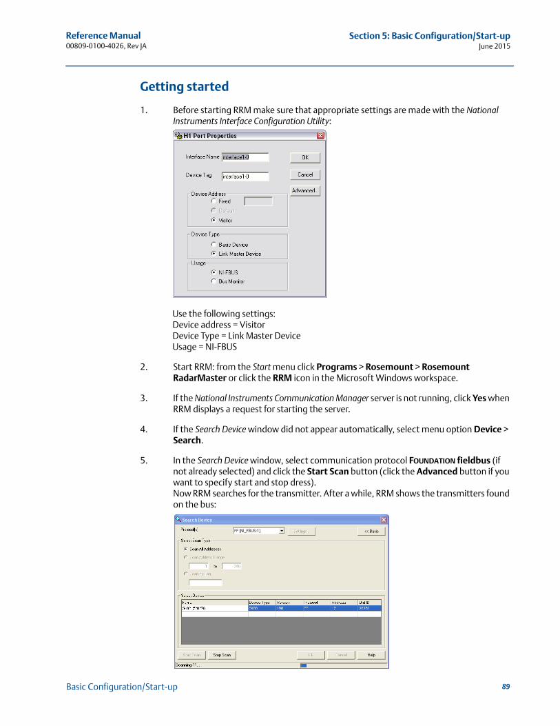
Reference Manual 00809-0100-4026, Rev JA
Section 5: Basic Configuration/Start-upJune 2015
Getting started
1. Before starting RRM make sure that appropriate settings are made with the National Instruments Interface Configuration Utility:
Use the following settings:Device address = VisitorDevice Type = Link Master DeviceUsage = NI-FBUS
2. Start RRM: from the Start menu click Programs > Rosemount > Rosemount RadarMaster or click the RRM icon in the Microsoft Windows workspace.
3. If the National Instruments Communication Manager server is not running, click Yes when RRM displays a request for starting the server.
4. If the Search Device window did not appear automatically, select menu option Device > Search.
5. In the Search Device window, select communication protocol FOUNDATION fieldbus (if not already selected) and click the Start Scan button (click the Advanced button if you want to specify start and stop dress).Now RRM searches for the transmitter. After a while, RRM shows the transmitters found on the bus:
89Basic Configuration/Start-up
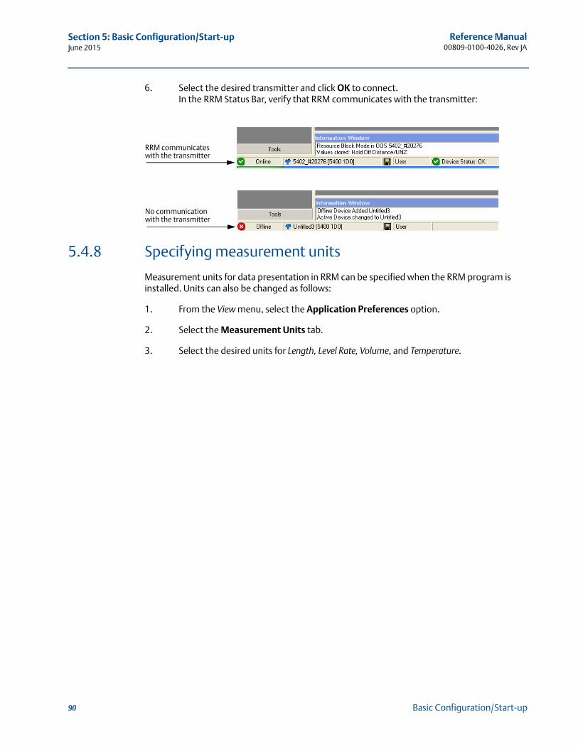
Reference Manual00809-0100-4026, Rev JA
Section 5: Basic Configuration/Start-upJune 2015
6. Select the desired transmitter and click OK to connect. In the RRM Status Bar, verify that RRM communicates with the transmitter:
5.4.8 Specifying measurement units
Measurement units for data presentation in RRM can be specified when the RRM program is installed. Units can also be changed as follows:
1. From the View menu, select the Application Preferences option.
2. Select the Measurement Units tab.
3. Select the desired units for Length, Level Rate, Volume, and Temperature.
RRM communicates with the transmitter
No communication with the transmitter
90 Basic Configuration/Start-up
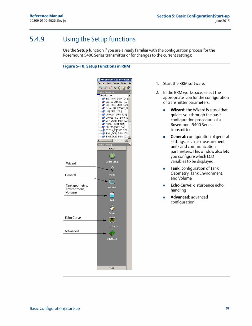
Reference Manual 00809-0100-4026, Rev JA
Section 5: Basic Configuration/Start-upJune 2015
5.4.9 Using the Setup functions
Use the Setup function if you are already familiar with the configuration process for the Rosemount 5400 Series transmitter or for changes to the current settings:
Figure 5-10. Setup Functions in RRM
1. Start the RRM software.
2. In the RRM workspace, select the appropriate icon for the configuration of transmitter parameters:
Wizard: the Wizard is a tool that guides you through the basic configuration procedure of a Rosemount 5400 Series transmitter
General: configuration of general settings, such as measurement units and communication parameters. This window also lets you configure which LCD variables to be displayed.
Tank: configuration of Tank Geometry, Tank Environment, and Volume
Echo Curve: disturbance echo handling
Advanced: advanced configuration
General
Echo Curve
Advanced
Wizard
Tank geometry, Environment, Volume
91Basic Configuration/Start-up
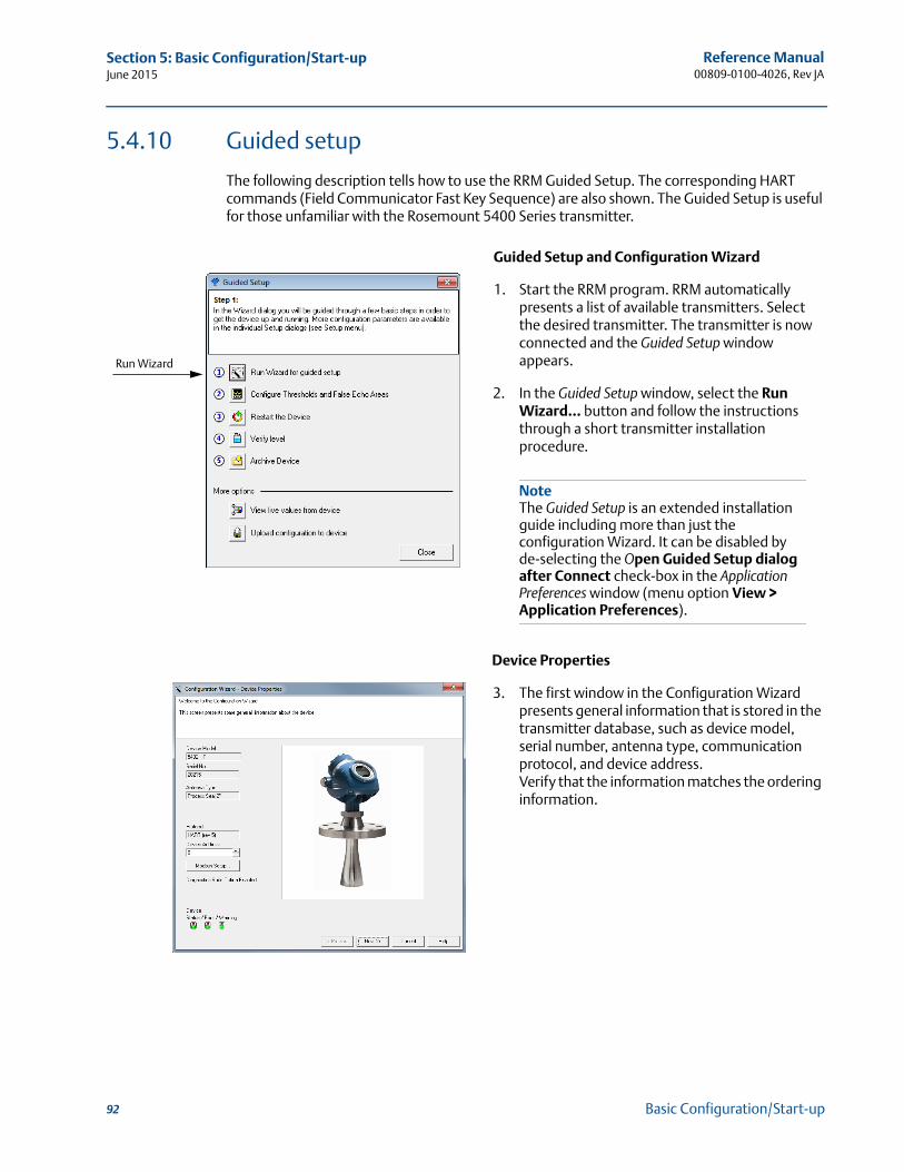
Reference Manual00809-0100-4026, Rev JA
Section 5: Basic Configuration/Start-upJune 2015
5.4.10 Guided setup
The following description tells how to use the RRM Guided Setup. The corresponding HART commands (Field Communicator Fast Key Sequence) are also shown. The Guided Setup is useful for those unfamiliar with the Rosemount 5400 Series transmitter.
Guided Setup and Configuration Wizard
1. Start the RRM program. RRM automatically presents a list of available transmitters. Select the desired transmitter. The transmitter is now connected and the Guided Setup window appears.
2. In the Guided Setup window, select the Run Wizard... button and follow the instructions through a short transmitter installation procedure.
Device Properties
3. The first window in the Configuration Wizard presents general information that is stored in the transmitter database, such as device model, serial number, antenna type, communication protocol, and device address.Verify that the information matches the ordering information.
Run Wizard
NoteThe Guided Setup is an extended installation guide including more than just the configuration Wizard. It can be disabled by de-selecting the Open Guided Setup dialog after Connect check-box in the Application Preferences window (menu option View > Application Preferences).
92 Basic Configuration/Start-up
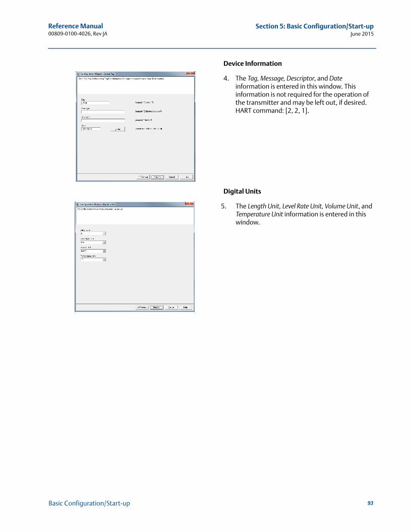
Reference Manual 00809-0100-4026, Rev JA
Section 5: Basic Configuration/Start-upJune 2015
Device Information
4. The Tag, Message, Descriptor, and Date information is entered in this window. This information is not required for the operation of the transmitter and may be left out, if desired.HART command: [2, 2, 1].
Digital Units
5. The Length Unit, Level Rate Unit, Volume Unit, and Temperature Unit information is entered in this window.
93Basic Configuration/Start-up
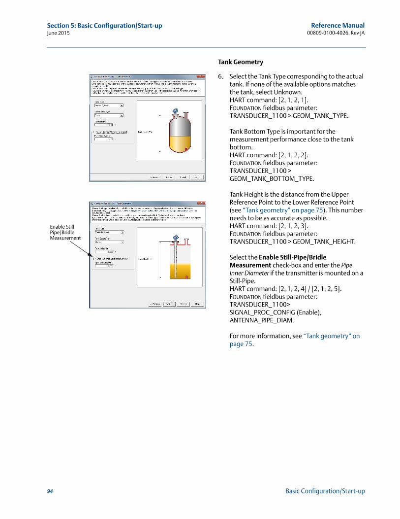
Reference Manual00809-0100-4026, Rev JA
Section 5: Basic Configuration/Start-upJune 2015
Tank Geometry
6. Select the Tank Type corresponding to the actual tank. If none of the available options matches the tank, select Unknown. HART command: [2, 1, 2, 1].FOUNDATION fieldbus parameter: TRANSDUCER_1100 > GEOM_TANK_TYPE.
Tank Bottom Type is important for the measurement performance close to the tank bottom.HART command: [2, 1, 2, 2].FOUNDATION fieldbus parameter: TRANSDUCER_1100 > GEOM_TANK_BOTTOM_TYPE.
Tank Height is the distance from the Upper Reference Point to the Lower Reference Point (see “Tank geometry” on page 75). This number needs to be as accurate as possible.HART command: [2, 1, 2, 3].FOUNDATION fieldbus parameter: TRANSDUCER_1100 > GEOM_TANK_HEIGHT.
Select the Enable Still-Pipe/Bridle Measurement check-box and enter the Pipe Inner Diameter if the transmitter is mounted on a Still-Pipe. HART command: [2, 1, 2, 4] / [2, 1, 2, 5].FOUNDATION fieldbus parameter: TRANSDUCER_1100>SIGNAL_PROC_CONFIG (Enable), ANTENNA_PIPE_DIAM.
For more information, see “Tank geometry” on page 75.
Enable Still Pipe/Bridle Measurement
94 Basic Configuration/Start-up
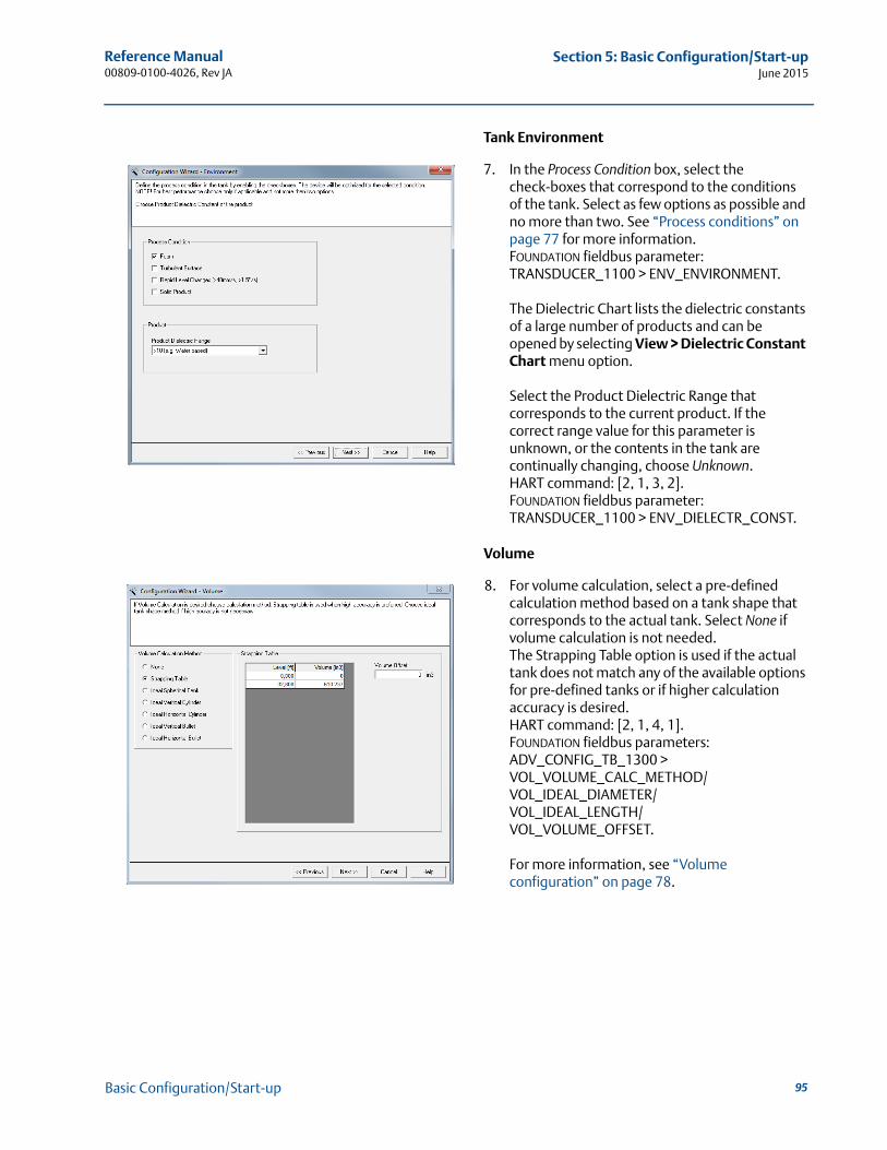
Reference Manual 00809-0100-4026, Rev JA
Section 5: Basic Configuration/Start-upJune 2015
Tank Environment
7. In the Process Condition box, select the check-boxes that correspond to the conditions of the tank. Select as few options as possible and no more than two. See “Process conditions” on page 77 for more information.FOUNDATION fieldbus parameter: TRANSDUCER_1100 > ENV_ENVIRONMENT.
The Dielectric Chart lists the dielectric constants of a large number of products and can be opened by selecting View > Dielectric Constant Chart menu option.
Select the Product Dielectric Range that corresponds to the current product. If the correct range value for this parameter is unknown, or the contents in the tank are continually changing, choose Unknown.HART command: [2, 1, 3, 2].FOUNDATION fieldbus parameter: TRANSDUCER_1100 > ENV_DIELECTR_CONST.
Volume
8. For volume calculation, select a pre-defined calculation method based on a tank shape that corresponds to the actual tank. Select None if volume calculation is not needed.The Strapping Table option is used if the actual tank does not match any of the available options for pre-defined tanks or if higher calculation accuracy is desired.HART command: [2, 1, 4, 1].FOUNDATION fieldbus parameters: ADV_CONFIG_TB_1300 >VOL_VOLUME_CALC_METHOD/VOL_IDEAL_DIAMETER/VOL_IDEAL_LENGTH/VOL_VOLUME_OFFSET.
For more information, see “Volume configuration” on page 78.
95Basic Configuration/Start-up
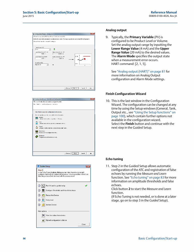
Reference Manual00809-0100-4026, Rev JA
Section 5: Basic Configuration/Start-upJune 2015
Analog output
9. Typically, the Primary Variable (PV) is configured to be Product Level or Volume.Set the analog output range by inputting the Lower Range Value (4 mA) and the Upper Range Value (20 mA) to the desired values. The Alarm Mode specifies the output state when a measurement error occurs.HART command: [2, 1, 5].
See “Analog output (HART)” on page 81 for more information on Analog Output configuration and Alarm Mode settings.
Finish Configuration Wizard
10. This is the last window in the Configuration Wizard. The configuration can be changed at any time by using the Setup windows (General, Tank, Output etc., see “Using the Setup functions” on page 100), which contain further options not available in the configuration wizard.Select the Finish button and continue with the next step in the Guided Setup.
Echo tuning
11. Step 2 in the Guided Setup allows automatic configuration of the ATC and registration of false echoes by running the Measure and Learn function. See “Echo tuning” on page 83 for more information on amplitude thresholds and false echoes.Click button 2 to start the Measure and Learn function.(If Echo Tuning is not needed, or is done at a later stage, go on to step 3 in the Guided Setup).
96 Basic Configuration/Start-up
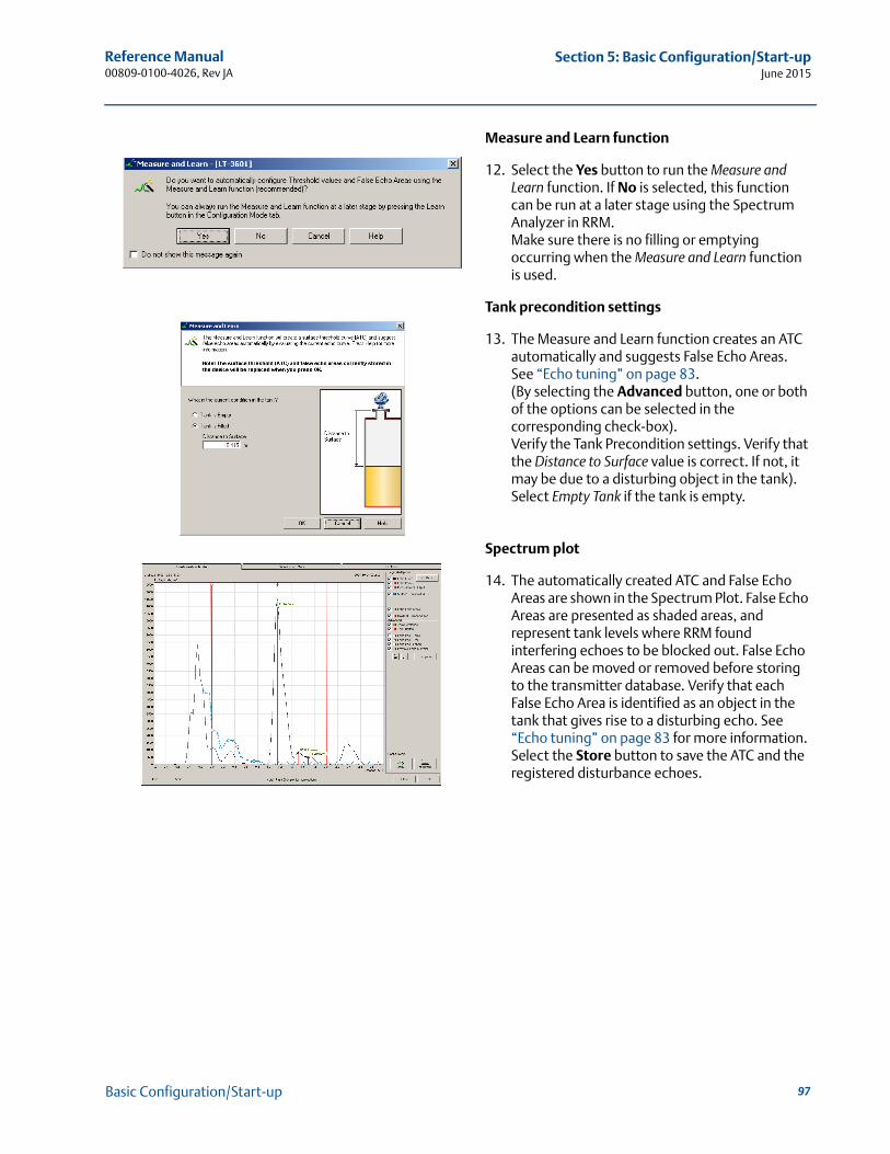
Reference Manual 00809-0100-4026, Rev JA
Section 5: Basic Configuration/Start-upJune 2015
Measure and Learn function
12. Select the Yes button to run the Measure and Learn function. If No is selected, this function can be run at a later stage using the Spectrum Analyzer in RRM.Make sure there is no filling or emptying occurring when the Measure and Learn function is used.
Tank precondition settings
13. The Measure and Learn function creates an ATC automatically and suggests False Echo Areas. See “Echo tuning” on page 83. (By selecting the Advanced button, one or both of the options can be selected in the corresponding check-box).Verify the Tank Precondition settings. Verify that the Distance to Surface value is correct. If not, it may be due to a disturbing object in the tank). Select Empty Tank if the tank is empty.
Spectrum plot
14. The automatically created ATC and False Echo Areas are shown in the Spectrum Plot. False Echo Areas are presented as shaded areas, and represent tank levels where RRM found interfering echoes to be blocked out. False Echo Areas can be moved or removed before storing to the transmitter database. Verify that each False Echo Area is identified as an object in the tank that gives rise to a disturbing echo. See “Echo tuning” on page 83 for more information.Select the Store button to save the ATC and the registered disturbance echoes.
97Basic Configuration/Start-up
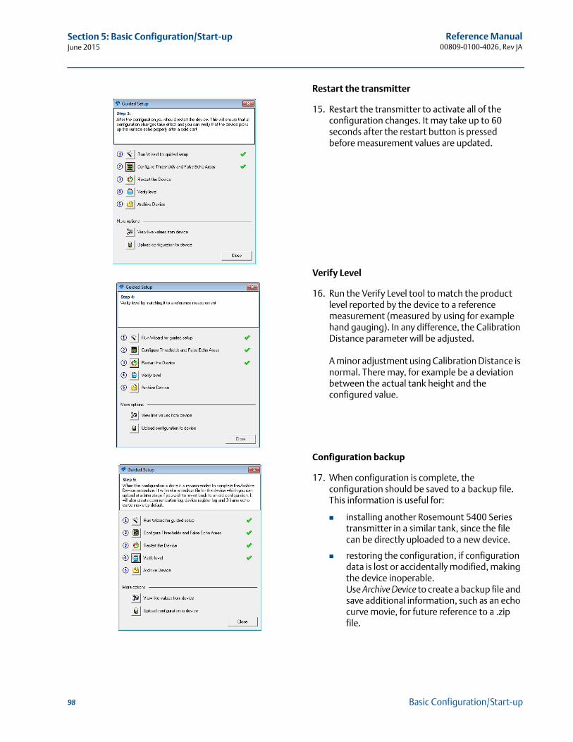
Reference Manual00809-0100-4026, Rev JA
Section 5: Basic Configuration/Start-upJune 2015
Restart the transmitter
15. Restart the transmitter to activate all of the configuration changes. It may take up to 60 seconds after the restart button is pressed before measurement values are updated.
Verify Level
16. Run the Verify Level tool to match the product level reported by the device to a reference measurement (measured by using for example hand gauging). In any difference, the Calibration Distance parameter will be adjusted.
A minor adjustment using Calibration Distance is normal. There may, for example be a deviation between the actual tank height and the configured value.
Configuration backup
17. When configuration is complete, the configuration should be saved to a backup file.This information is useful for:
installing another Rosemount 5400 Series transmitter in a similar tank, since the file can be directly uploaded to a new device.
restoring the configuration, if configuration data is lost or accidentally modified, making the device inoperable.Use Archive Device to create a backup file and save additional information, such as an echo curve movie, for future reference to a .zip file.
98 Basic Configuration/Start-up
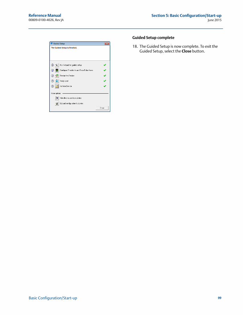
Reference Manual 00809-0100-4026, Rev JA
Section 5: Basic Configuration/Start-upJune 2015
Guided Setup complete
18. The Guided Setup is now complete. To exit the Guided Setup, select the Close button.
99Basic Configuration/Start-up
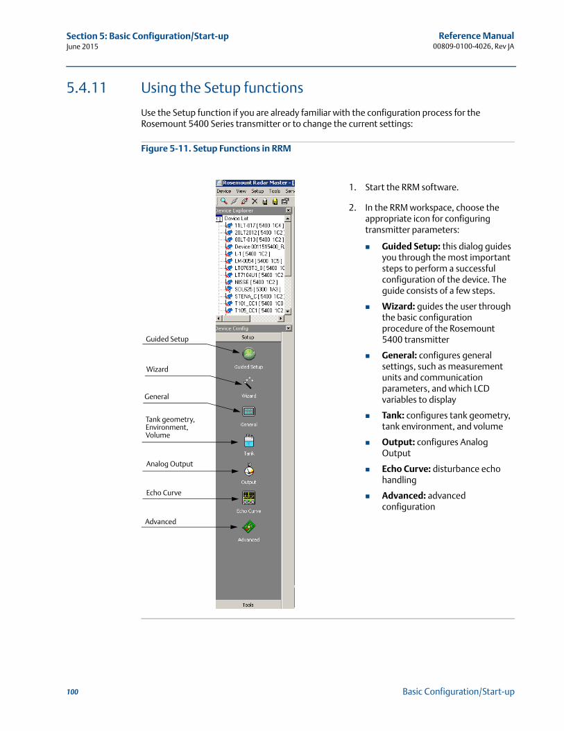
Reference Manual00809-0100-4026, Rev JA
Section 5: Basic Configuration/Start-upJune 2015
5.4.11 Using the Setup functions
Use the Setup function if you are already familiar with the configuration process for the Rosemount 5400 Series transmitter or to change the current settings:
Figure 5-11. Setup Functions in RRM
1. Start the RRM software.
2. In the RRM workspace, choose the appropriate icon for configuring transmitter parameters:
Guided Setup: this dialog guides you through the most important steps to perform a successful configuration of the device. The guide consists of a few steps.
Wizard: guides the user through the basic configuration procedure of the Rosemount 5400 transmitter
General: configures general settings, such as measurement units and communication parameters, and which LCD variables to display
Tank: configures tank geometry, tank environment, and volume
Output: configures Analog Output
Echo Curve: disturbance echo handling
Advanced: advanced configuration
General
Echo Curve
Advanced
Wizard
Analog Output
Tank geometry, Environment, Volume
Guided Setup
100 Basic Configuration/Start-up
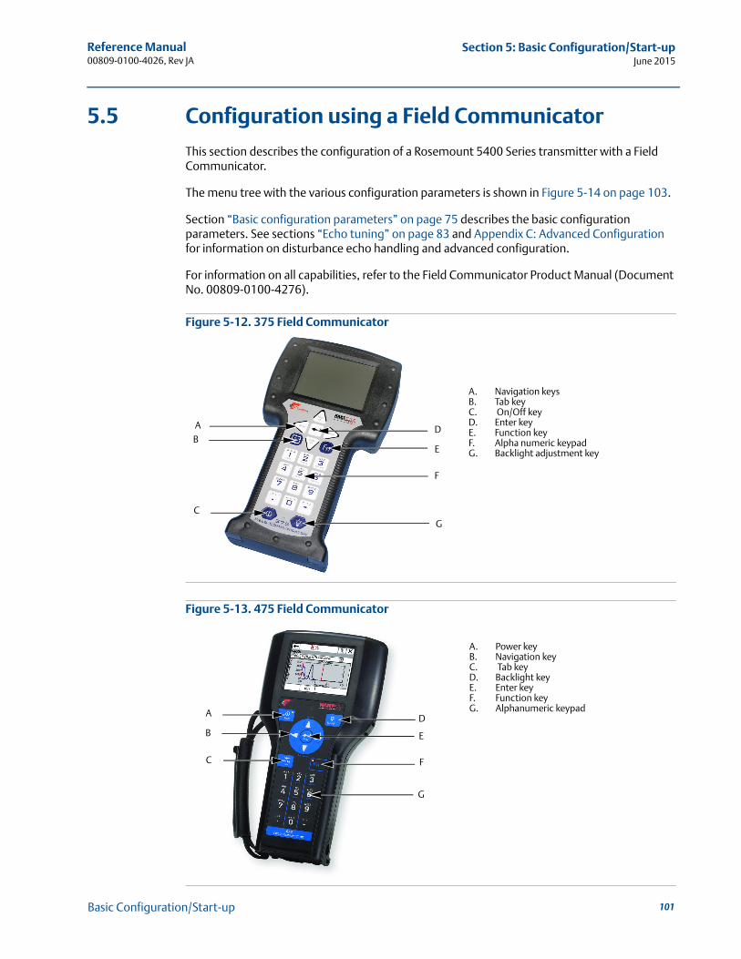
Reference Manual 00809-0100-4026, Rev JA
Section 5: Basic Configuration/Start-upJune 2015
5.5 Configuration using a Field Communicator
This section describes the configuration of a Rosemount 5400 Series transmitter with a Field Communicator.
The menu tree with the various configuration parameters is shown in Figure 5-14 on page 103.
Section “Basic configuration parameters” on page 75 describes the basic configuration parameters. See sections “Echo tuning” on page 83 and Appendix C: Advanced Configuration for information on disturbance echo handling and advanced configuration.
For information on all capabilities, refer to the Field Communicator Product Manual (Document No. 00809-0100-4276).
Figure 5-12. 375 Field Communicator
Figure 5-13. 475 Field Communicator
E
A
G
DB
C
F
A. Navigation keysB. Tab keyC. On/Off keyD. Enter keyE. Function keyF. Alpha numeric keypadG. Backlight adjustment key
B
C
E
F
G
DA
A. Power keyB. Navigation keyC. Tab keyD. Backlight keyE. Enter keyF. Function keyG. Alphanumeric keypad
101Basic Configuration/Start-up
Reference Manual00809-0100-4026, Rev JA
Section 5: Basic Configuration/Start-upJune 2015
To make a basic setup of the transmitter, do the following:
1. Check that the desired Measurement Units are selected. HART command: [2, 1, 1, 5].
2. Enter configuration parameters for the following:
Device info. HART command: [2, 2, 1]
Geometry. HART command: [2, 1, 2]
Environment. HART command: [2, 1, 3]
Volume. HART command: [2, 1, 4]
Analog Out. HART command: [2, 1, 5]
3. Run Measure and Learn. HART command: [2, 1, 6, 2]. This function creates an ATC.
4. Restart the transmitter. HART command: [2, 1, 6, 4].
To view the Echo Curve and adjust threshold settings, see “Using the Echo Curve Analyzer” on page 139.
102 Basic Configuration/Start-up
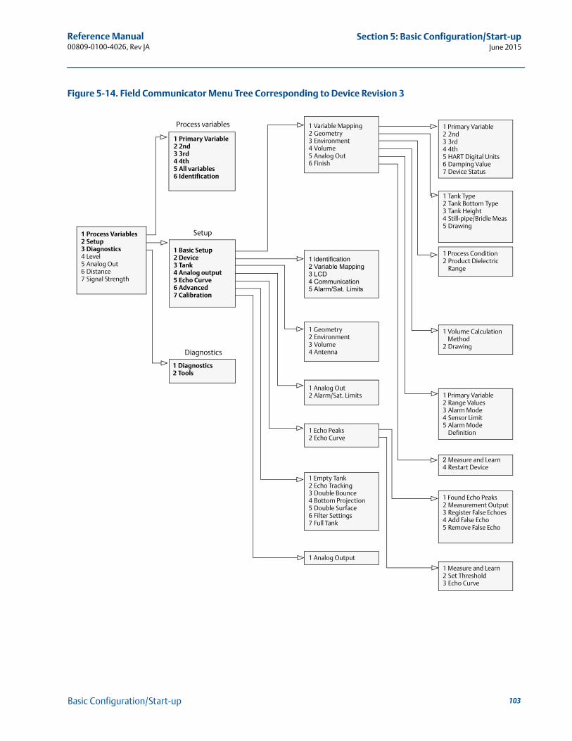
Reference Manual 00809-0100-4026, Rev JA
Section 5: Basic Configuration/Start-upJune 2015
Figure 5-14. Field Communicator Menu Tree Corresponding to Device Revision 3
Process variables
1 Process Variables2 Setup3 Diagnostics4 Level5 Analog Out6 Distance7 Signal Strength
1 Primary Variable2 2nd3 3rd4 4th5 All variables6 Identification
1 Basic Setup2 Device3 Tank4 Analog output5 Echo Curve6 Advanced7 Calibration
1 Diagnostics2 Tools
1 Variable Mapping2 Geometry3 Environment4 Volume5 Analog Out6 Finish
1 Identification2 Variable Mapping3 LCD4 Communication5 Alarm/Sat. Limits
1 Geometry2 Environment3 Volume4 Antenna
1 Analog Out2 Alarm/Sat. Limits
1 Echo Peaks2 Echo Curve
1 Empty Tank2 Echo Tracking3 Double Bounce4 Bottom Projection5 Double Surface6 Filter Settings7 Full Tank
1 Analog Output
Setup
Diagnostics
1 Primary Variable2 2nd3 3rd4 4th5 HART Digital Units6 Damping Value7 Device Status
1 Tank Type2 Tank Bottom Type3 Tank Height4 Still-pipe/Bridle Meas5 Drawing
1 Process Condition2 Product Dielectric
Range
1 Volume Calculation Method
2 Drawing
1 Primary Variable2 Range Values3 Alarm Mode4 Sensor Limit5 Alarm Mode
Definition
2 Measure and Learn4 Restart Device
1 Found Echo Peaks2 Measurement Output3 Register False Echoes4 Add False Echo5 Remove False Echo
1 Measure and Learn2 Set Threshold3 Echo Curve
103Basic Configuration/Start-up
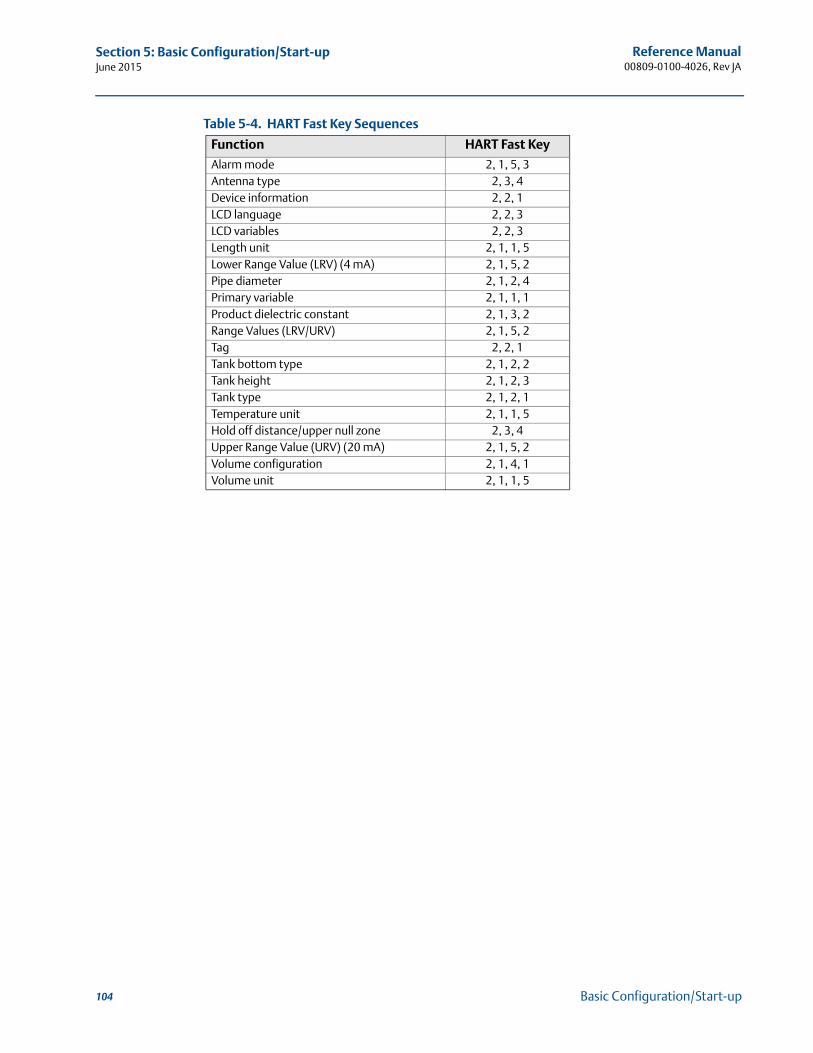
Reference Manual00809-0100-4026, Rev JA
Section 5: Basic Configuration/Start-upJune 2015
Table 5-4. HART Fast Key Sequences
Function HART Fast Key
Alarm mode 2, 1, 5, 3Antenna type 2, 3, 4Device information 2, 2, 1LCD language 2, 2, 3LCD variables 2, 2, 3Length unit 2, 1, 1, 5Lower Range Value (LRV) (4 mA) 2, 1, 5, 2Pipe diameter 2, 1, 2, 4Primary variable 2, 1, 1, 1Product dielectric constant 2, 1, 3, 2Range Values (LRV/URV) 2, 1, 5, 2Tag 2, 2, 1Tank bottom type 2, 1, 2, 2Tank height 2, 1, 2, 3Tank type 2, 1, 2, 1Temperature unit 2, 1, 1, 5Hold off distance/upper null zone 2, 3, 4Upper Range Value (URV) (20 mA) 2, 1, 5, 2Volume configuration 2, 1, 4, 1Volume unit 2, 1, 1, 5
104 Basic Configuration/Start-up
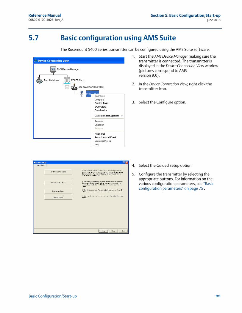
Reference Manual 00809-0100-4026, Rev JA
Section 5: Basic Configuration/Start-upJune 2015
5.7 Basic configuration using AMS Suite
The Rosemount 5400 Series transmitter can be configured using the AMS Suite software:
1. Start the AMS Device Manager making sure the transmitter is connected. The transmitter is displayed in the Device Connection View window (pictures correspond to AMS version 9.0).
2. In the Device Connection View, right click the transmitter icon.
3. Select the Configure option.
4. Select the Guided Setup option.
5. Configure the transmitter by selecting the appropriate buttons. For information on the various configuration parameters, see “Basic configuration parameters” on page 75 .
105Basic Configuration/Start-up
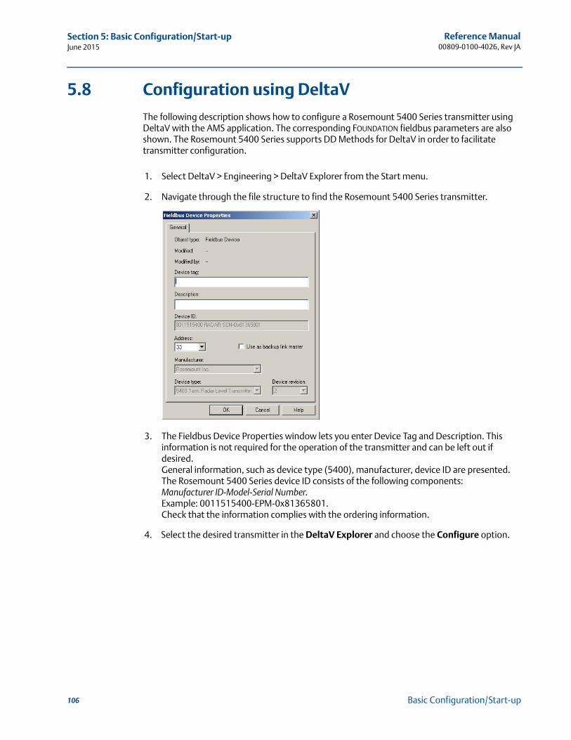
Reference Manual00809-0100-4026, Rev JA
Section 5: Basic Configuration/Start-upJune 2015
5.8 Configuration using DeltaV
The following description shows how to configure a Rosemount 5400 Series transmitter using DeltaV with the AMS application. The corresponding FOUNDATION fieldbus parameters are also shown. The Rosemount 5400 Series supports DD Methods for DeltaV in order to facilitate transmitter configuration.
1. Select DeltaV > Engineering > DeltaV Explorer from the Start menu.
2. Navigate through the file structure to find the Rosemount 5400 Series transmitter.
3. The Fieldbus Device Properties window lets you enter Device Tag and Description. This information is not required for the operation of the transmitter and can be left out if desired.General information, such as device type (5400), manufacturer, device ID are presented. The Rosemount 5400 Series device ID consists of the following components:Manufacturer ID-Model-Serial Number. Example: 0011515400-EPM-0x81365801.Check that the information complies with the ordering information.
4. Select the desired transmitter in the DeltaV Explorer and choose the Configure option.
106 Basic Configuration/Start-up
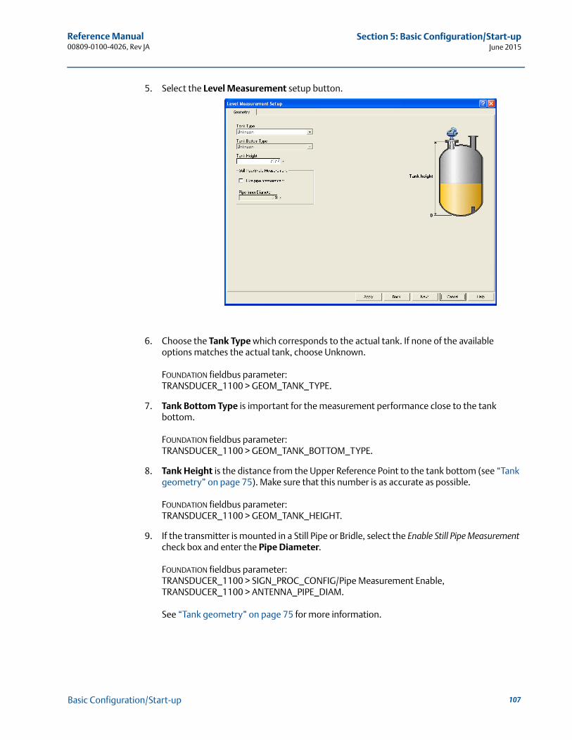
Reference Manual 00809-0100-4026, Rev JA
Section 5: Basic Configuration/Start-upJune 2015
5. Select the Level Measurement setup button.
6. Choose the Tank Type which corresponds to the actual tank. If none of the available options matches the actual tank, choose Unknown.
FOUNDATION fieldbus parameter: TRANSDUCER_1100 > GEOM_TANK_TYPE.
7. Tank Bottom Type is important for the measurement performance close to the tank bottom.
FOUNDATION fieldbus parameter: TRANSDUCER_1100 > GEOM_TANK_BOTTOM_TYPE.
8. Tank Height is the distance from the Upper Reference Point to the tank bottom (see “Tank geometry” on page 75). Make sure that this number is as accurate as possible.
FOUNDATION fieldbus parameter: TRANSDUCER_1100 > GEOM_TANK_HEIGHT.
9. If the transmitter is mounted in a Still Pipe or Bridle, select the Enable Still Pipe Measurement check box and enter the Pipe Diameter.
FOUNDATION fieldbus parameter: TRANSDUCER_1100 > SIGN_PROC_CONFIG/Pipe Measurement Enable,TRANSDUCER_1100 > ANTENNA_PIPE_DIAM.
See “Tank geometry” on page 75 for more information.
107Basic Configuration/Start-up
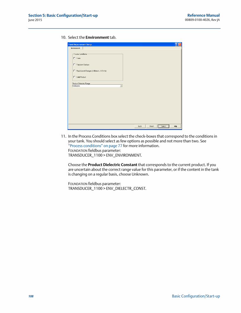
Reference Manual00809-0100-4026, Rev JA
Section 5: Basic Configuration/Start-upJune 2015
10. Select the Environment tab.
11. In the Process Conditions box select the check-boxes that correspond to the conditions in your tank. You should select as few options as possible and not more than two. See “Process conditions” on page 77 for more information.FOUNDATION fieldbus parameter: TRANSDUCER_1100 > ENV_ENVIRONMENT.
Choose the Product Dielectric Constant that corresponds to the current product. If you are uncertain about the correct range value for this parameter, or if the content in the tank is changing on a regular basis, choose Unknown.
FOUNDATION fieldbus parameter: TRANSDUCER_1100 > ENV_DIELECTR_CONST.
108 Basic Configuration/Start-up
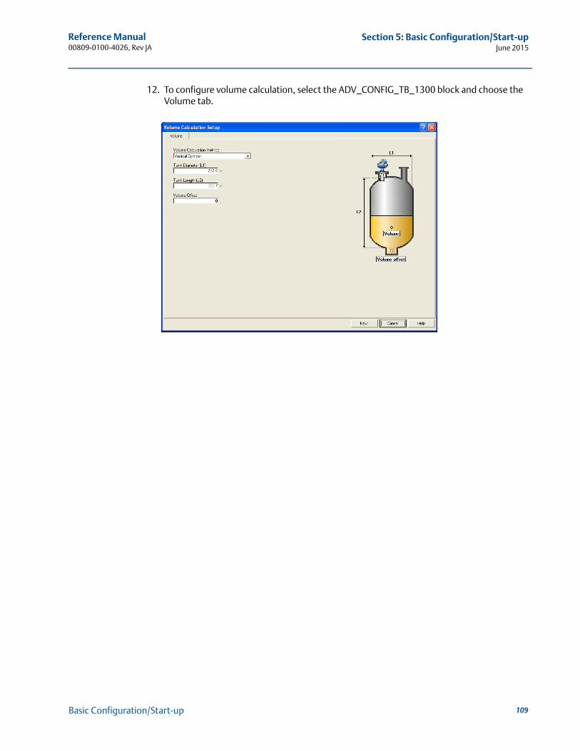
Reference Manual 00809-0100-4026, Rev JA
Section 5: Basic Configuration/Start-upJune 2015
12. To configure volume calculation, select the ADV_CONFIG_TB_1300 block and choose the Volume tab.
109Basic Configuration/Start-up
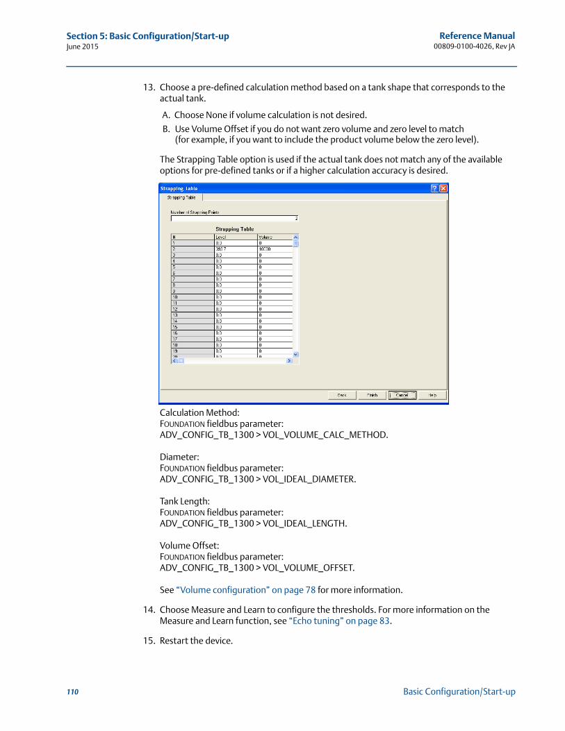
Reference Manual00809-0100-4026, Rev JA
Section 5: Basic Configuration/Start-upJune 2015
13. Choose a pre-defined calculation method based on a tank shape that corresponds to the actual tank.
A. Choose None if volume calculation is not desired.
B. Use Volume Offset if you do not want zero volume and zero level to match (for example, if you want to include the product volume below the zero level).
The Strapping Table option is used if the actual tank does not match any of the available options for pre-defined tanks or if a higher calculation accuracy is desired.
Calculation Method:FOUNDATION fieldbus parameter: ADV_CONFIG_TB_1300 > VOL_VOLUME_CALC_METHOD.
Diameter:FOUNDATION fieldbus parameter: ADV_CONFIG_TB_1300 > VOL_IDEAL_DIAMETER.
Tank Length:FOUNDATION fieldbus parameter: ADV_CONFIG_TB_1300 > VOL_IDEAL_LENGTH.
Volume Offset:FOUNDATION fieldbus parameter: ADV_CONFIG_TB_1300 > VOL_VOLUME_OFFSET.
See “Volume configuration” on page 78 for more information.
14. Choose Measure and Learn to configure the thresholds. For more information on the Measure and Learn function, see “Echo tuning” on page 83.
15. Restart the device.
110 Basic Configuration/Start-up
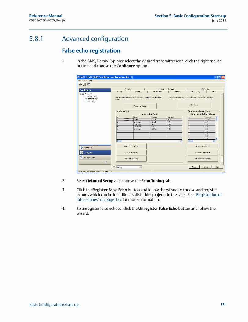
Reference Manual 00809-0100-4026, Rev JA
Section 5: Basic Configuration/Start-upJune 2015
5.8.1 Advanced configuration
False echo registration
1. In the AMS/DeltaV Explorer select the desired transmitter icon, click the right mouse button and choose the Configure option.
2. Select Manual Setup and choose the Echo Tuning tab.
3. Click the Register False Echo button and follow the wizard to choose and register echoes which can be identified as disturbing objects in the tank. See “Registration of false echoes” on page 137 for more information.
4. To unregister false echoes, click the Unregister False Echo button and follow the wizard.
111Basic Configuration/Start-up
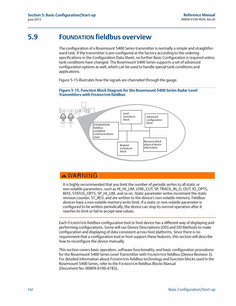
Reference Manual00809-0100-4026, Rev JA
Section 5: Basic Configuration/Start-upJune 2015
5.9 FOUNDATION fieldbus overview
The configuration of a Rosemount 5400 Series transmitter is normally a simple and straightfor-ward task. If the transmitter is pre-configured at the factory according to the ordering specifications in the Configuration Data Sheet, no further Basic Configuration is required unless tank conditions have changed. The Rosemount 5400 Series supports a set of advanced configuration options as well, which can be used to handle special tank conditions and applications.
Figure 5-15 illustrates how the signals are channeled through the gauge.
Figure 5-15. Function Block Diagram for the Rosemount 5400 Series Radar Level Transmitters with FOUNDATION fieldbus
Each FOUNDATION fieldbus configuration tool or host device has a different way of displaying and performing configurations. Some will use Device Descriptions (DD) and DD Methods to make configuration and displaying of data consistent across host platforms. Since there is no requirement that a configuration tool or host support these features, this section will describe how to reconfigure the device manually.
This section covers basic operation, software functionality, and basic configuration procedures for the Rosemount 5400 Series Level Transmitter with FOUNDATION fieldbus (Device Revision 3). For detailed information about FOUNDATION fieldbus technology and function blocks used in the Rosemount 5400 Series, refer to the FOUNDATION fieldbus Blocks Manual (Document No. 00809-0100-4783).
It is highly recommended that you limit the number of periodic writes to all static or non-volatile parameters, such as HI_HI_LIM, LOW_CUT, SP, TRACK_IN_D, OUT, IO_OPTS, BIAS, STATUS_OPTS, SP_HI_LIM, and so on. Static parameter writes increment the static revision counter, ST_REV, and are written to the device's non-volatile memory. Fieldbus devices have a non-volatile memory write limit. If a static or non-volatile parameter is configured to be written periodically, the device can stop its normal operation after it reaches its limit or fail to accept new values.
FOUNDATION fieldbuscompliantcommunicationsstack
Level transducer block
Register transducer block
Resource block physical device information
Advanced configuration block
112 Basic Configuration/Start-up
Reference Manual 00809-0100-4026, Rev JA
Section 5: Basic Configuration/Start-upJune 2015
5.9.1 Assigning device tag and node address
A Rosemount 5400 Series transmitter is shipped with a blank tag and a temporary address (unless specifically ordered with both) to allow a host to automatically assign an address and a tag. If the tag or address need to be changed, use the features of the configuration tool. The tool basically does the following:
1. Changes the address to a temporary address (248-251).
2. Changes the tag to a new value.
3. Changes the address to a new address.
When the transmitter is at a temporary address, only the tag and address can be changed or written to. The resource, transducer, and function blocks are all disabled.
5.9.2 FOUNDATION fieldbus block operation
Function blocks within the fieldbus device perform the various functions required for process control. Function blocks perform process control functions, such as Analog Input (AI) functions, as well as Proportional/Integral/Derivative (PID) functions. The standard function blocks provide a common structure for defining function block inputs, outputs, control parameters, events, alarms, and modes, and combining them into a process that can be implemented within a single device or over the fieldbus network. This simplifies the identification of characteristics that are common to function blocks.
In addition to function blocks, fieldbus devices contain two other block types to support the function blocks. These are the Resource block and the Transducer block.
Resource blocks contain the hardware-specific characteristics associated with a device; they have no input or output parameters. The algorithm within a resource block monitors and controls the general operation of the physical device hardware. There is only one resource block defined for a device.
Transducer blocks connect function blocks to local input/output functions. They read sensor hardware and write to effector (actuator) hardware.
Level transducer block
The Level Transducer block contains transmitter information including diagnostics and the ability to configure, set to factory defaults and restarting the transmitter.
Register transducer block
The Register Transducer block allows a service engineer to access all database registers in the device.
Advanced configuration transducer block
The advanced configuration transducer block contains functions such as amplitude threshold settings for filtering of disturbing echoes and noise, simulation of measurement values and strapping table for volume measurements.
113Basic Configuration/Start-up
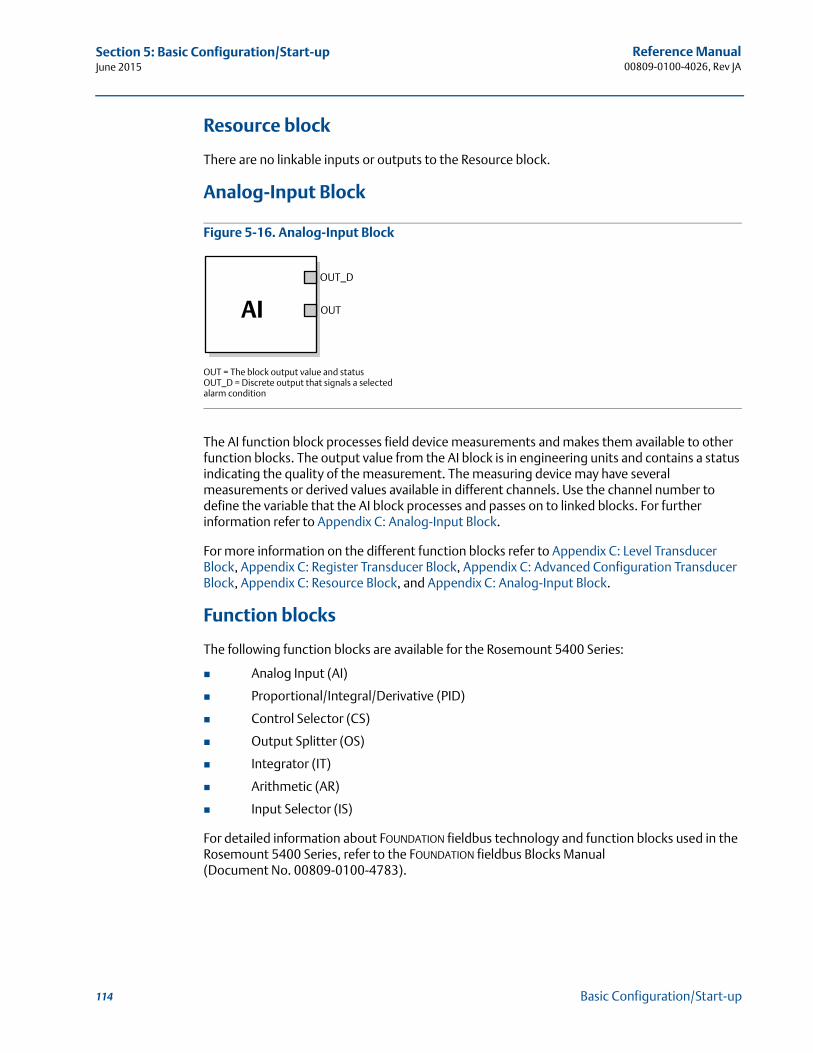
Reference Manual00809-0100-4026, Rev JA
Section 5: Basic Configuration/Start-upJune 2015
Resource block
There are no linkable inputs or outputs to the Resource block.
Analog-Input Block
Figure 5-16. Analog-Input Block
The AI function block processes field device measurements and makes them available to other function blocks. The output value from the AI block is in engineering units and contains a status indicating the quality of the measurement. The measuring device may have several measurements or derived values available in different channels. Use the channel number to define the variable that the AI block processes and passes on to linked blocks. For further information refer to Appendix C: Analog-Input Block.
For more information on the different function blocks refer to Appendix C: Level Transducer Block, Appendix C: Register Transducer Block, Appendix C: Advanced Configuration Transducer Block, Appendix C: Resource Block, and Appendix C: Analog-Input Block.
Function blocks
The following function blocks are available for the Rosemount 5400 Series:
Analog Input (AI)
Proportional/Integral/Derivative (PID)
Control Selector (CS)
Output Splitter (OS)
Integrator (IT)
Arithmetic (AR)
Input Selector (IS)
For detailed information about FOUNDATION fieldbus technology and function blocks used in the Rosemount 5400 Series, refer to the FOUNDATION fieldbus Blocks Manual (Document No. 00809-0100-4783).
OUT = The block output value and statusOUT_D = Discrete output that signals a selected alarm condition
OUT_D
OUTAI
114 Basic Configuration/Start-up
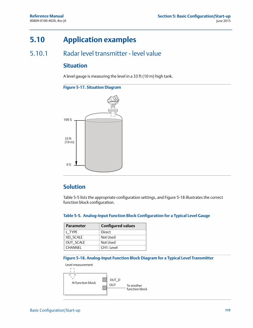
Reference Manual 00809-0100-4026, Rev JA
Section 5: Basic Configuration/Start-upJune 2015
5.10 Application examples
5.10.1 Radar level transmitter - level value
Situation
A level gauge is measuring the level in a 33 ft (10 m) high tank.
Figure 5-17. Situation Diagram
Solution
Table 5-5 lists the appropriate configuration settings, and Figure 5-18 illustrates the correct function block configuration.
Table 5-5. Analog-Input Function Block Configuration for a Typical Level Gauge
Figure 5-18. Analog-Input Function Block Diagram for a Typical Level Transmitter
Parameter Configured values
L_TYPE DirectXD_SCALE Not UsedOUT_SCALE Not UsedCHANNEL CH1: Level
33 ft(10 m)
100 %
0 %
Level measurement
To another function block
OUT_D
OUTAI function block
115Basic Configuration/Start-up
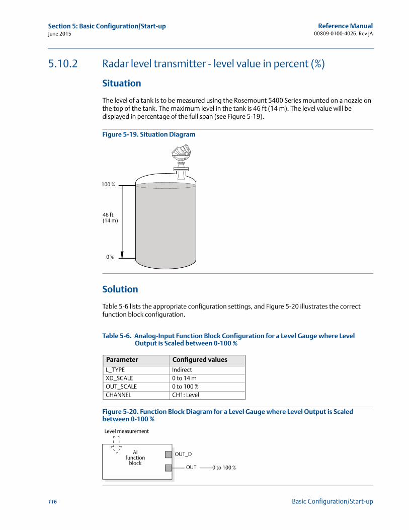
Reference Manual00809-0100-4026, Rev JA
Section 5: Basic Configuration/Start-upJune 2015
5.10.2 Radar level transmitter - level value in percent (%)
Situation
The level of a tank is to be measured using the Rosemount 5400 Series mounted on a nozzle on the top of the tank. The maximum level in the tank is 46 ft (14 m). The level value will be displayed in percentage of the full span (see Figure 5-19).
Figure 5-19. Situation Diagram
Solution
Table 5-6 lists the appropriate configuration settings, and Figure 5-20 illustrates the correct function block configuration.
Table 5-6. Analog-Input Function Block Configuration for a Level Gauge where Level Output is Scaled between 0-100 %
Figure 5-20. Function Block Diagram for a Level Gauge where Level Output is Scaled between 0-100 %
Parameter Configured values
L_TYPE IndirectXD_SCALE 0 to 14 mOUT_SCALE 0 to 100 %CHANNEL CH1: Level
46 ft(14 m)
100 %
0 %
Level measurement
AI function
block
OUT_D
OUT 0 to 100 %
116 Basic Configuration/Start-up
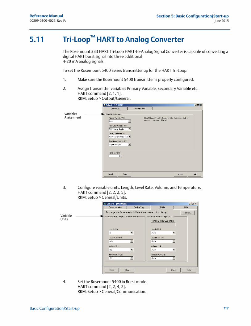
Reference Manual 00809-0100-4026, Rev JA
Section 5: Basic Configuration/Start-upJune 2015
5.11 Tri-Loop™ HART to Analog Converter
The Rosemount 333 HART Tri-Loop HART-to-Analog Signal Converter is capable of converting a digital HART burst signal into three additional 4-20 mA analog signals.
To set the Rosemount 5400 Series transmitter up for the HART Tri-Loop:
1. Make sure the Rosemount 5400 transmitter is properly configured.
2. Assign transmitter variables Primary Variable, Secondary Variable etc.HART command [2, 1, 1].RRM: Setup > Output/General.
3. Configure variable units: Length, Level Rate, Volume, and Temperature. HART command [2, 2, 2, 5].RRM: Setup > General/Units.
4. Set the Rosemount 5400 in Burst mode.HART command [2, 2, 4, 2].RRM: Setup > General/Communication.
Variables Assignment
Variable Units
117Basic Configuration/Start-up
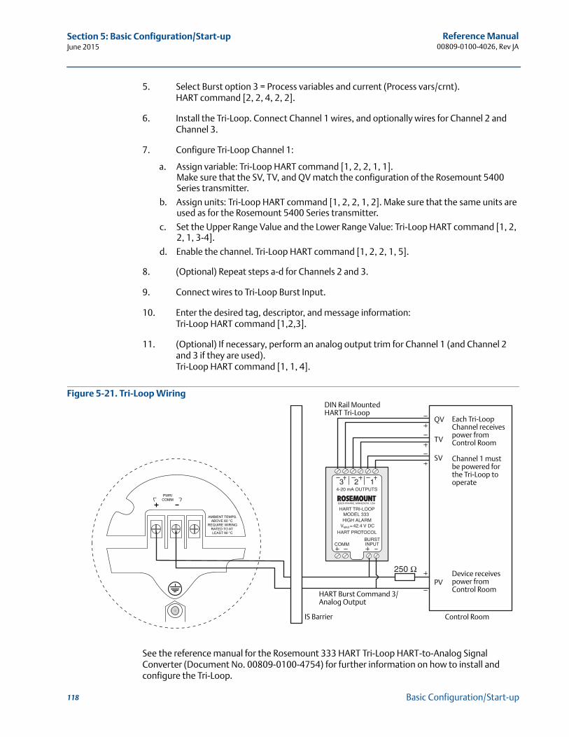
Reference Manual00809-0100-4026, Rev JA
Section 5: Basic Configuration/Start-upJune 2015
5. Select Burst option 3 = Process variables and current (Process vars/crnt).HART command [2, 2, 4, 2, 2].
6. Install the Tri-Loop. Connect Channel 1 wires, and optionally wires for Channel 2 and Channel 3.
7. Configure Tri-Loop Channel 1:
a. Assign variable: Tri-Loop HART command [1, 2, 2, 1, 1].Make sure that the SV, TV, and QV match the configuration of the Rosemount 5400 Series transmitter.
b. Assign units: Tri-Loop HART command [1, 2, 2, 1, 2]. Make sure that the same units are used as for the Rosemount 5400 Series transmitter.
c. Set the Upper Range Value and the Lower Range Value: Tri-Loop HART command [1, 2, 2, 1, 3-4].
d. Enable the channel. Tri-Loop HART command [1, 2, 2, 1, 5].
8. (Optional) Repeat steps a-d for Channels 2 and 3.
9. Connect wires to Tri-Loop Burst Input.
10. Enter the desired tag, descriptor, and message information:Tri-Loop HART command [1,2,3].
11. (Optional) If necessary, perform an analog output trim for Channel 1 (and Channel 2 and 3 if they are used).Tri-Loop HART command [1, 1, 4].
Figure 5-21. Tri-Loop Wiring
See the reference manual for the Rosemount 333 HART Tri-Loop HART-to-Analog Signal Converter (Document No. 00809-0100-4754) for further information on how to install and configure the Tri-Loop.
Each Tri-Loop Channel receives power from Control Room
Channel 1 must be powered for the Tri-Loop to operate
Device receives power from Control Room
HART Burst Command 3/Analog Output
IS Barrier
DIN Rail MountedHART Tri-Loop
Control Room
QV
TV
SV
PV
118 Basic Configuration/Start-up
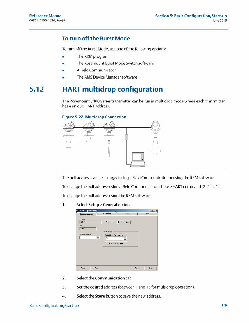
Reference Manual 00809-0100-4026, Rev JA
Section 5: Basic Configuration/Start-upJune 2015
To turn off the Burst Mode
To turn off the Burst Mode, use one of the following options:
The RRM program
The Rosemount Burst Mode Switch software
A Field Communicator
The AMS Device Manager software
5.12 HART multidrop configuration
The Rosemount 5400 Series transmitter can be run in multidrop mode where each transmitter has a unique HART address.
Figure 5-22. Multidrop Connection
The poll address can be changed using a Field Communicator or using the RRM software.
To change the poll address using a Field Communicator, choose HART command [2, 2, 4, 1].
To change the poll address using the RRM software:
1. Select Setup > General option.
2. Select the Communication tab.
3. Set the desired address (between 1 and 15 for multidrop operation).
4. Select the Store button to save the new address.
119Basic Configuration/Start-up

120
Reference Manual00809-0100-4026, Rev JA
Section 5: Basic Configuration/Start-upJune 2015
Basic Configuration/Start-up
Reference Manual 00809-0100-4026, Rev JA
Section 6: OperationJune 2015
Section 6 Operation
Safety messages . . . . . . . . . . . . . . . . . . . . . . . . . . . . . . . . . . . . . . . . . . . . . . . . . . . . . . . . . . . . page 121Viewing measurement data . . . . . . . . . . . . . . . . . . . . . . . . . . . . . . . . . . . . . . . . . . . . . . . . . . page 122LCD display error messages . . . . . . . . . . . . . . . . . . . . . . . . . . . . . . . . . . . . . . . . . . . . . . . . . . page 128LED error messages . . . . . . . . . . . . . . . . . . . . . . . . . . . . . . . . . . . . . . . . . . . . . . . . . . . . . . . . . page 129
6.1 Safety messagesProcedures and instructions in this manual may require special precautions to ensure the safety of the personnel performing the operations. Information that raises potential safety issues is indicated by a warning symbol ( ). Refer to the safety messages listed at the beginning of each section before performing an operation preceded by this symbol.
Failure to follow these installation guidelines could result in death or serious injury.
Make sure only qualified personnel perform the installation. Use the equipment only as specified in this manual. Failure to do so may impair the
protection provided by the equipment.Explosions could result in death or serious injury.
Verify that the operating environment of the transmitter is consistent with the appropriate hazardous locations certifications.
Before connecting a Field Communicator in an explosive atmosphere, make sure the instruments in the loop are installed in accordance with intrinsically safe or non-incendive field wiring practices.
Electrical shock could cause death or serious injury.
Use extreme caution when making contact with the leads and terminals.Antennas with non-conducting surfaces.
Antennas with non-conducting surfaces (e.g. Rod antenna and Process Seal antenna) may generate an ignition-capable level of electrostatic charge under extreme conditions. Therefore, when the antenna is used in a potentially explosive atmosphere, appropriate measures must be taken to prevent electrostatic discharge.
Any substitution of non-authorized parts or repair, other than exchanging the complete transmitter head or antenna assembly, may jeopardize safety and is prohibited.Unauthorized changes to the product are strictly prohibited as they may unintentionally and unpredictably alter performance and jeopardize safety. Unauthorized changes that interfere with the integrity of the welds or flanges, such as making additional perforations, compromise product integrity and safety. Equipment ratings and certifications are no longer valid on any products that have been damaged or modified without the prior written permission of Emerson Process Management. Any continued use of product that has been damaged or modified without prior written authorization is at the customer's sole risk and expense.
121Operation
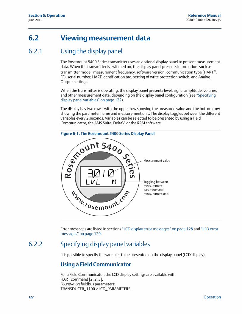
Reference Manual00809-0100-4026, Rev JA
Section 6: OperationJune 2015
6.2 Viewing measurement data
6.2.1 Using the display panel
The Rosemount 5400 Series transmitter uses an optional display panel to present measurement data. When the transmitter is switched on, the display panel presents information, such as transmitter model, measurement frequency, software version, communication type (HART®, FF), serial number, HART identification tag, setting of write protection switch, and Analog Output settings.
When the transmitter is operating, the display panel presents level, signal amplitude, volume, and other measurement data, depending on the display panel configuration (see “Specifying display panel variables” on page 122).
The display has two rows, with the upper row showing the measured value and the bottom row showing the parameter name and measurement unit. The display toggles between the different variables every 2 seconds. Variables can be selected to be presented by using a Field Communicator, the AMS Suite, DeltaV, or the RRM software.
Figure 6-1. The Rosemount 5400 Series Display Panel
Error messages are listed in sections “LCD display error messages” on page 128 and “LED error messages” on page 129.
6.2.2 Specifying display panel variables
It is possible to specify the variables to be presented on the display panel (LCD display).
Using a Field Communicator
For a Field Communicator, the LCD display settings are available with HART command [2, 2, 3].FOUNDATION fieldbus parameters:TRANSDUCER_1100 > LCD_PARAMETERS.
Toggling between measurement parameter and measurement unit
Measurement value
122 Operation
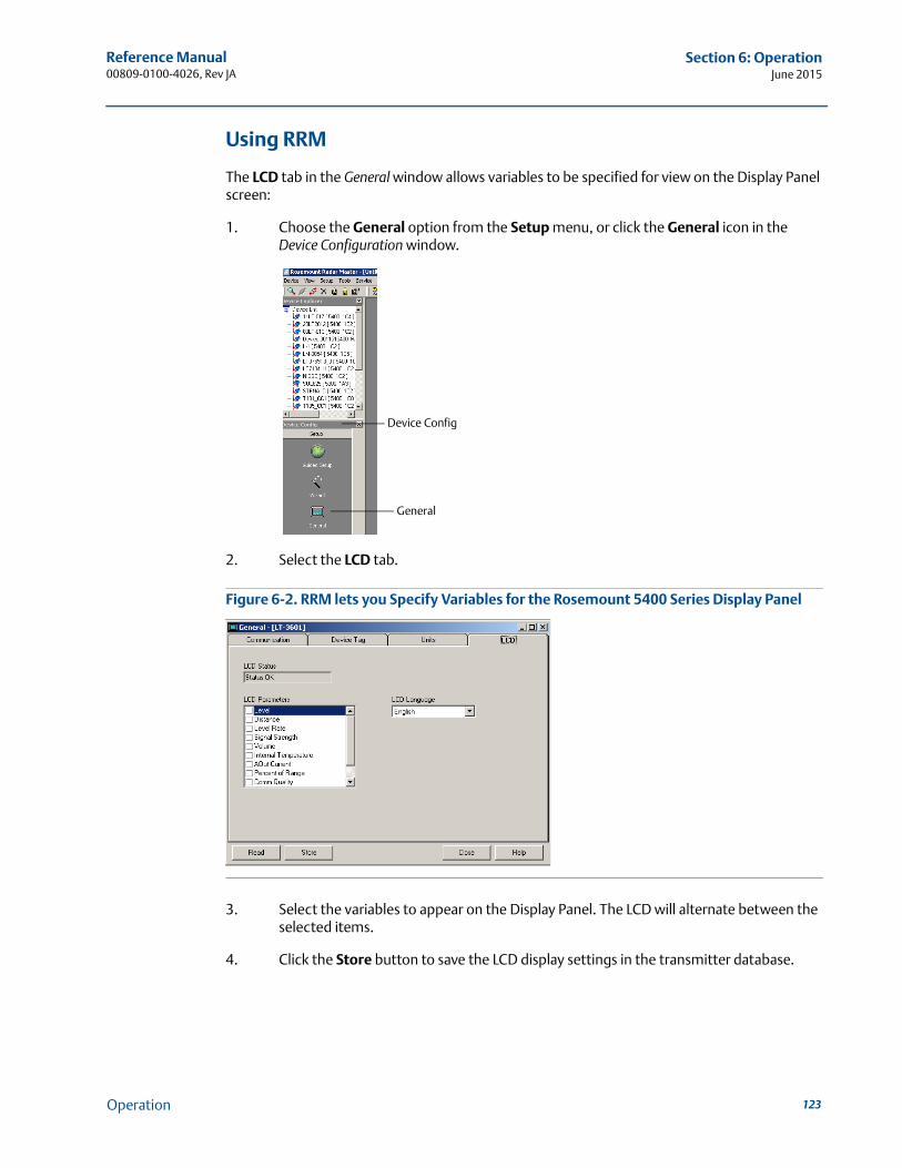
Reference Manual 00809-0100-4026, Rev JA
Section 6: OperationJune 2015
Using RRM
The LCD tab in the General window allows variables to be specified for view on the Display Panel screen:
1. Choose the General option from the Setup menu, or click the General icon in the Device Configuration window.
2. Select the LCD tab.
Figure 6-2. RRM lets you Specify Variables for the Rosemount 5400 Series Display Panel
3. Select the variables to appear on the Display Panel. The LCD will alternate between the selected items.
4. Click the Store button to save the LCD display settings in the transmitter database.
Device Config
General
123Operation
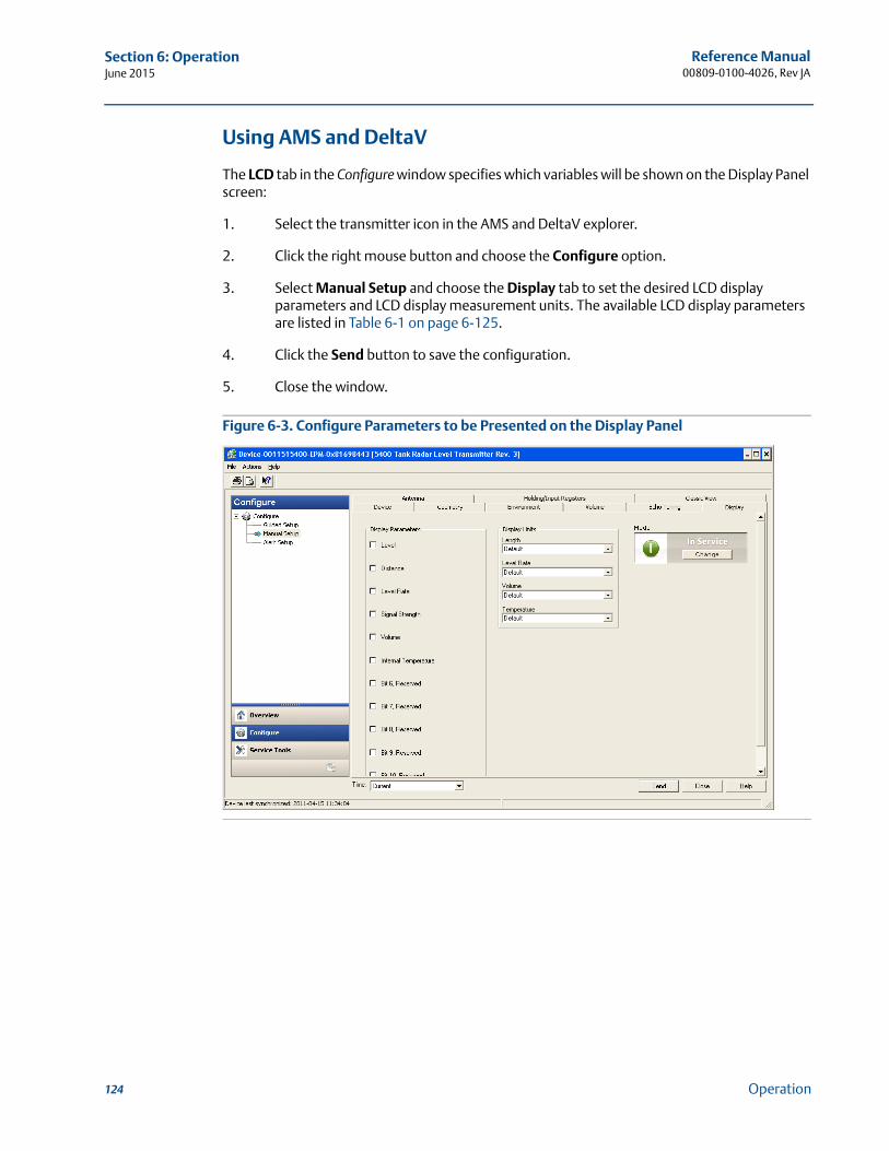
Reference Manual00809-0100-4026, Rev JA
Section 6: OperationJune 2015
Using AMS and DeltaV
The LCD tab in the Configure window specifies which variables will be shown on the Display Panel screen:
1. Select the transmitter icon in the AMS and DeltaV explorer.
2. Click the right mouse button and choose the Configure option.
3. Select Manual Setup and choose the Display tab to set the desired LCD display parameters and LCD display measurement units. The available LCD display parameters are listed in Table 6-1 on page 6-125.
4. Click the Send button to save the configuration.
5. Close the window.
Figure 6-3. Configure Parameters to be Presented on the Display Panel
124 Operation
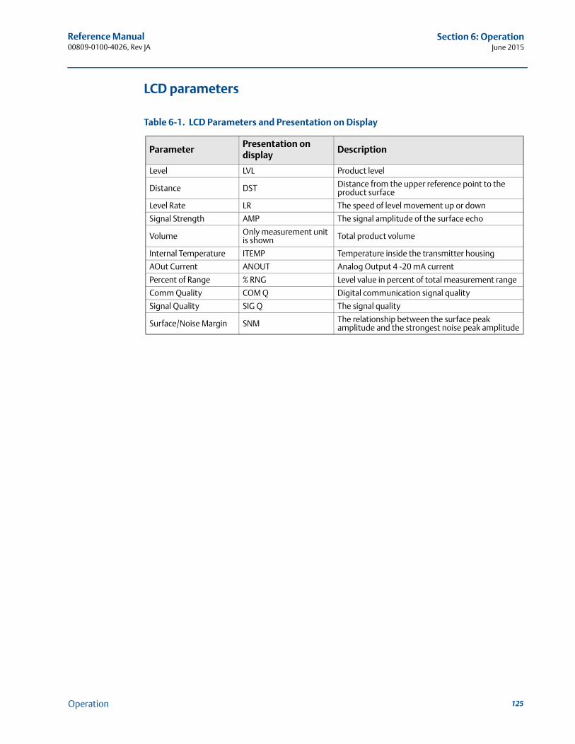
Reference Manual 00809-0100-4026, Rev JA
Section 6: OperationJune 2015
LCD parameters
Table 6-1. LCD Parameters and Presentation on Display
ParameterPresentation on display
Description
Level LVL Product level
Distance DST Distance from the upper reference point to the product surface
Level Rate LR The speed of level movement up or down
Signal Strength AMP The signal amplitude of the surface echo
Volume Only measurement unit is shown Total product volume
Internal Temperature ITEMP Temperature inside the transmitter housing
AOut Current ANOUT Analog Output 4 -20 mA current
Percent of Range % RNG Level value in percent of total measurement range
Comm Quality COM Q Digital communication signal quality
Signal Quality SIG Q The signal quality
Surface/Noise Margin SNM The relationship between the surface peak amplitude and the strongest noise peak amplitude
125Operation
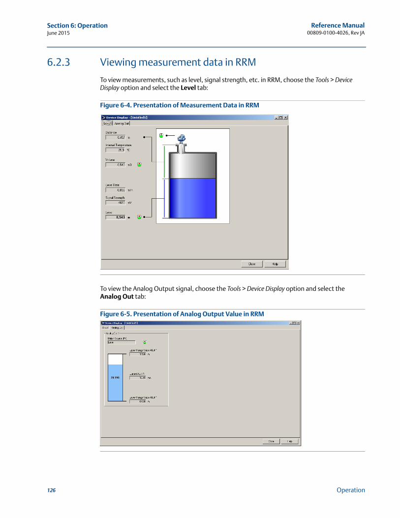
Reference Manual00809-0100-4026, Rev JA
Section 6: OperationJune 2015
6.2.3 Viewing measurement data in RRM
To view measurements, such as level, signal strength, etc. in RRM, choose the Tools > Device Display option and select the Level tab:
Figure 6-4. Presentation of Measurement Data in RRM
To view the Analog Output signal, choose the Tools > Device Display option and select the Analog Out tab:
Figure 6-5. Presentation of Analog Output Value in RRM
126 Operation
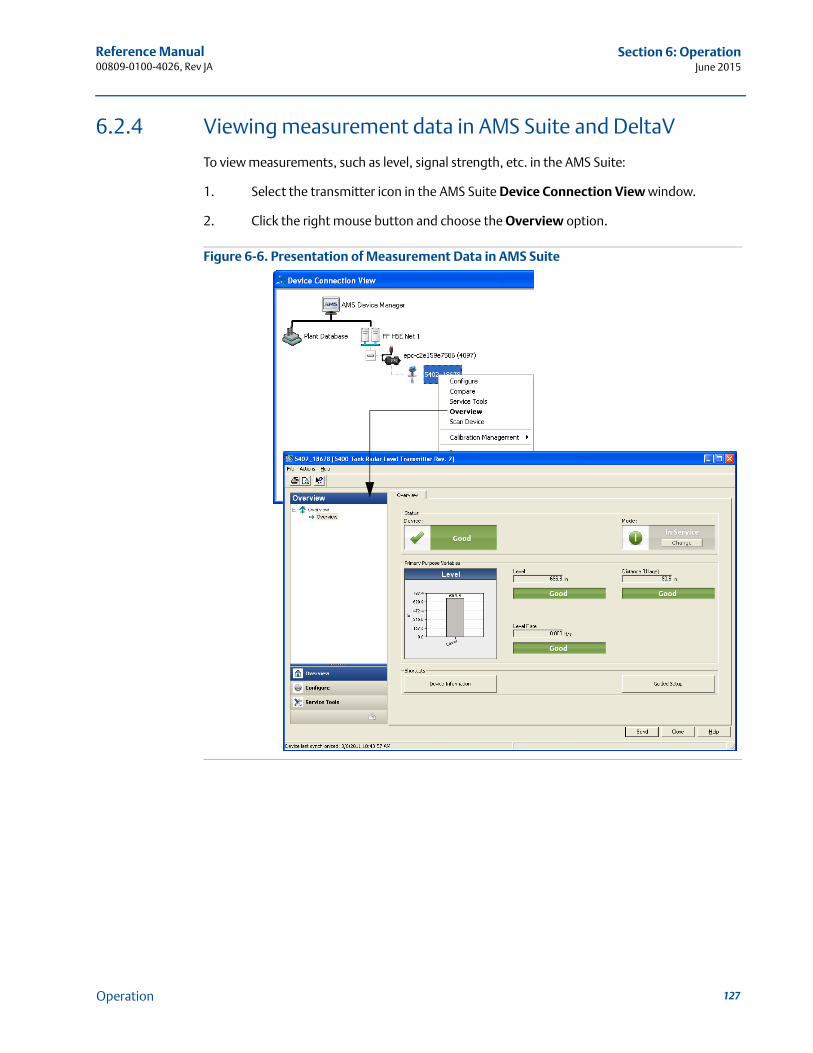
Reference Manual 00809-0100-4026, Rev JA
Section 6: OperationJune 2015
6.2.4 Viewing measurement data in AMS Suite and DeltaV
To view measurements, such as level, signal strength, etc. in the AMS Suite:
1. Select the transmitter icon in the AMS Suite Device Connection View window.
2. Click the right mouse button and choose the Overview option.
Figure 6-6. Presentation of Measurement Data in AMS Suite
127Operation
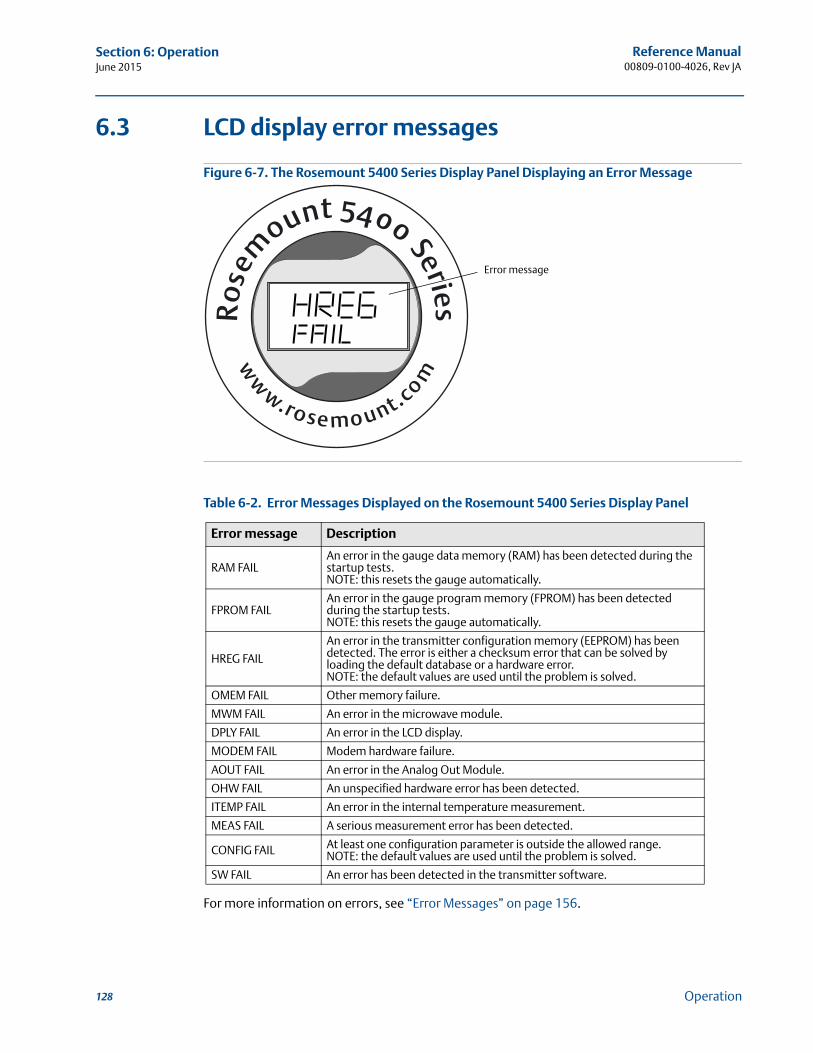
Reference Manual00809-0100-4026, Rev JA
Section 6: OperationJune 2015
6.3 LCD display error messages
Figure 6-7. The Rosemount 5400 Series Display Panel Displaying an Error Message
Table 6-2. Error Messages Displayed on the Rosemount 5400 Series Display Panel
For more information on errors, see “Error Messages” on page 156.
Error message Description
RAM FAILAn error in the gauge data memory (RAM) has been detected during the startup tests. NOTE: this resets the gauge automatically.
FPROM FAILAn error in the gauge program memory (FPROM) has been detected during the startup tests. NOTE: this resets the gauge automatically.
HREG FAIL
An error in the transmitter configuration memory (EEPROM) has been detected. The error is either a checksum error that can be solved by loading the default database or a hardware error.NOTE: the default values are used until the problem is solved.
OMEM FAIL Other memory failure.
MWM FAIL An error in the microwave module.
DPLY FAIL An error in the LCD display.
MODEM FAIL Modem hardware failure.
AOUT FAIL An error in the Analog Out Module.
OHW FAIL An unspecified hardware error has been detected.
ITEMP FAIL An error in the internal temperature measurement.
MEAS FAIL A serious measurement error has been detected.
CONFIG FAIL At least one configuration parameter is outside the allowed range. NOTE: the default values are used until the problem is solved.
SW FAIL An error has been detected in the transmitter software.
Error message
128 Operation
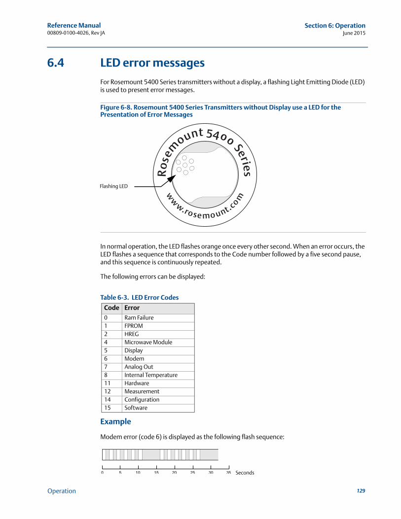
Reference Manual 00809-0100-4026, Rev JA
Section 6: OperationJune 2015
6.4 LED error messages
For Rosemount 5400 Series transmitters without a display, a flashing Light Emitting Diode (LED) is used to present error messages.
Figure 6-8. Rosemount 5400 Series Transmitters without Display use a LED for the Presentation of Error Messages
In normal operation, the LED flashes orange once every other second. When an error occurs, the LED flashes a sequence that corresponds to the Code number followed by a five second pause, and this sequence is continuously repeated.
The following errors can be displayed:
Table 6-3. LED Error Codes
Example
Modem error (code 6) is displayed as the following flash sequence:
Code Error
0 Ram Failure1 FPROM2 HREG4 Microwave Module5 Display6 Modem7 Analog Out8 Internal Temperature11 Hardware12 Measurement14 Configuration15 Software
Flashing LED
Seconds
129Operation

130
Reference Manual00809-0100-4026, Rev JA
Section 6: OperationJune 2015
Operation
Reference Manual 00809-0100-4026, Rev JA
Section 7: Service and TroubleshootingJune 2015
Section 7 Service and Troubleshooting
Safety messages . . . . . . . . . . . . . . . . . . . . . . . . . . . . . . . . . . . . . . . . . . . . . . . . . . . . . . . . . . . . page 131Troubleshooting overview . . . . . . . . . . . . . . . . . . . . . . . . . . . . . . . . . . . . . . . . . . . . . . . . . . . page 133Service overview . . . . . . . . . . . . . . . . . . . . . . . . . . . . . . . . . . . . . . . . . . . . . . . . . . . . . . . . . . . . page 134Analog output calibration . . . . . . . . . . . . . . . . . . . . . . . . . . . . . . . . . . . . . . . . . . . . . . . . . . . . page 144Logging measurement data . . . . . . . . . . . . . . . . . . . . . . . . . . . . . . . . . . . . . . . . . . . . . . . . . . page 145Backing up the transmitter configuration . . . . . . . . . . . . . . . . . . . . . . . . . . . . . . . . . . . . . . page 146Diagnostics . . . . . . . . . . . . . . . . . . . . . . . . . . . . . . . . . . . . . . . . . . . . . . . . . . . . . . . . . . . . . . . . page 147Configuration report . . . . . . . . . . . . . . . . . . . . . . . . . . . . . . . . . . . . . . . . . . . . . . . . . . . . . . . . page 149Viewing input and holding registers . . . . . . . . . . . . . . . . . . . . . . . . . . . . . . . . . . . . . . . . . . . page 150Reset to factory settings . . . . . . . . . . . . . . . . . . . . . . . . . . . . . . . . . . . . . . . . . . . . . . . . . . . . . page 151Surface search . . . . . . . . . . . . . . . . . . . . . . . . . . . . . . . . . . . . . . . . . . . . . . . . . . . . . . . . . . . . . . page 152Using the Simulation Mode . . . . . . . . . . . . . . . . . . . . . . . . . . . . . . . . . . . . . . . . . . . . . . . . . . page 153Write protecting a transmitter . . . . . . . . . . . . . . . . . . . . . . . . . . . . . . . . . . . . . . . . . . . . . . . . page 154Diagnostic messages . . . . . . . . . . . . . . . . . . . . . . . . . . . . . . . . . . . . . . . . . . . . . . . . . . . . . . . . page 155Troubleshooting . . . . . . . . . . . . . . . . . . . . . . . . . . . . . . . . . . . . . . . . . . . . . . . . . . . . . . . . . . . . page 165
7.1 Safety messages
Procedures and instructions in this manual may require special precautions to ensure the safety of the personnel performing the operations. Information that raises potential safety issues is indicated by a warning symbol ( ). Refer to the safety messages listed at the beginning of each section before performing an operation preceded by this symbol.
NoteThe antenna seal assembly should under no circumstances be disassembled.
131Service and Troubleshooting
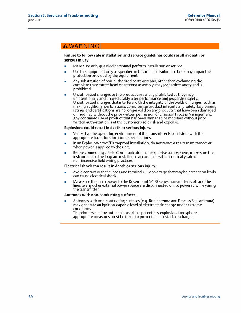
Reference Manual00809-0100-4026, Rev JA
Section 7: Service and TroubleshootingJune 2015
Failure to follow safe installation and service guidelines could result in death or serious injury.
Make sure only qualified personnel perform installation or service. Use the equipment only as specified in this manual. Failure to do so may impair the
protection provided by the equipment. Any substitution of non-authorized parts or repair, other than exchanging the
complete transmitter head or antenna assembly, may jeopardize safety and is prohibited.
Unauthorized changes to the product are strictly prohibited as they may unintentionally and unpredictably alter performance and jeopardize safety. Unauthorized changes that interfere with the integrity of the welds or flanges, such as making additional perforations, compromise product integrity and safety. Equipment ratings and certifications are no longer valid on any products that have been damaged or modified without the prior written permission of Emerson Process Management. Any continued use of product that has been damaged or modified without prior written authorization is at the customer's sole risk and expense.
Explosions could result in death or serious injury.
Verify that the operating environment of the transmitter is consistent with the appropriate hazardous locations specifications.
In an Explosion-proof/Flameproof installation, do not remove the transmitter cover when power is applied to the unit.
Before connecting a Field Communicator in an explosive atmosphere, make sure the instruments in the loop are installed in accordance with intrinsically safe or non-incendive field wiring practices.
Electrical shock can result in death or serious injury.
Avoid contact with the leads and terminals. High voltage that may be present on leads can cause electrical shock.
Make sure the main power to the Rosemount 5400 Series transmitter is off and the lines to any other external power source are disconnected or not powered while wiring the transmitter.
Antennas with non-conducting surfaces.
Antennas with non-conducting surfaces (e.g. Rod antenna and Process Seal antenna) may generate an ignition-capable level of electrostatic charge under extreme conditions.Therefore, when the antenna is used in a potentially explosive atmosphere, appropriate measures must be taken to prevent electrostatic discharge.
132 Service and Troubleshooting
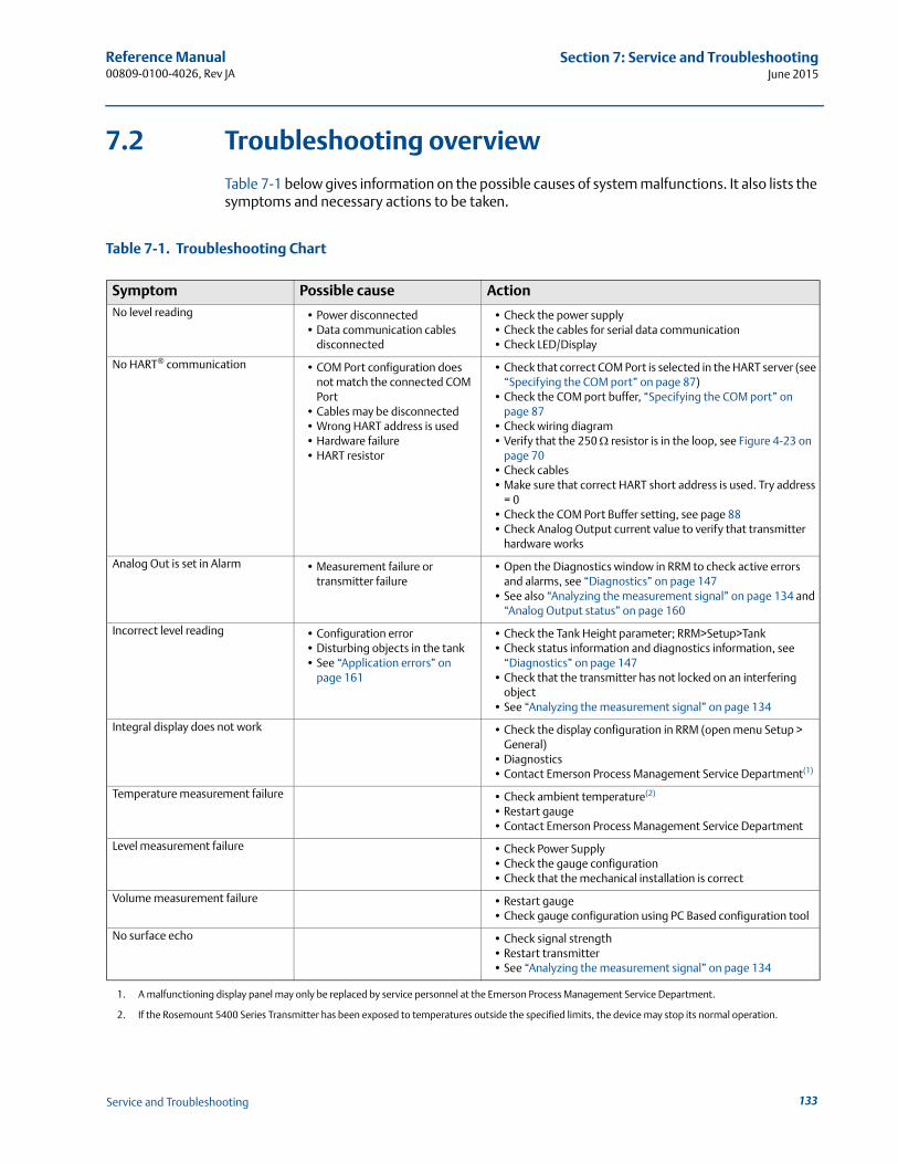
Reference Manual 00809-0100-4026, Rev JA
Section 7: Service and TroubleshootingJune 2015
7.2 Troubleshooting overview
Table 7-1 below gives information on the possible causes of system malfunctions. It also lists the symptoms and necessary actions to be taken.
Table 7-1. Troubleshooting Chart
Symptom Possible cause ActionNo level reading • Power disconnected
• Data communication cables disconnected
• Check the power supply• Check the cables for serial data communication• Check LED/Display
No HART® communication • COM Port configuration does not match the connected COM Port
• Cables may be disconnected• Wrong HART address is used• Hardware failure• HART resistor
• Check that correct COM Port is selected in the HART server (see “Specifying the COM port” on page 87)
• Check the COM port buffer, “Specifying the COM port” on page 87
• Check wiring diagram• Verify that the 250 resistor is in the loop, see Figure 4-23 on
page 70• Check cables• Make sure that correct HART short address is used. Try address
= 0• Check the COM Port Buffer setting, see page 88• Check Analog Output current value to verify that transmitter
hardware works
Analog Out is set in Alarm • Measurement failure or transmitter failure
• Open the Diagnostics window in RRM to check active errors and alarms, see “Diagnostics” on page 147
• See also “Analyzing the measurement signal” on page 134 and “Analog Output status” on page 160
Incorrect level reading • Configuration error• Disturbing objects in the tank• See “Application errors” on
page 161
• Check the Tank Height parameter; RRM>Setup>Tank• Check status information and diagnostics information, see
“Diagnostics” on page 147• Check that the transmitter has not locked on an interfering
object• See “Analyzing the measurement signal” on page 134
Integral display does not work • Check the display configuration in RRM (open menu Setup > General)
• Diagnostics• Contact Emerson Process Management Service Department(1)
1. A malfunctioning display panel may only be replaced by service personnel at the Emerson Process Management Service Department.
Temperature measurement failure • Check ambient temperature(2)
• Restart gauge• Contact Emerson Process Management Service Department
2. If the Rosemount 5400 Series Transmitter has been exposed to temperatures outside the specified limits, the device may stop its normal operation.
Level measurement failure • Check Power Supply• Check the gauge configuration• Check that the mechanical installation is correct
Volume measurement failure • Restart gauge• Check gauge configuration using PC Based configuration tool
No surface echo • Check signal strength• Restart transmitter• See “Analyzing the measurement signal” on page 134
133Service and Troubleshooting
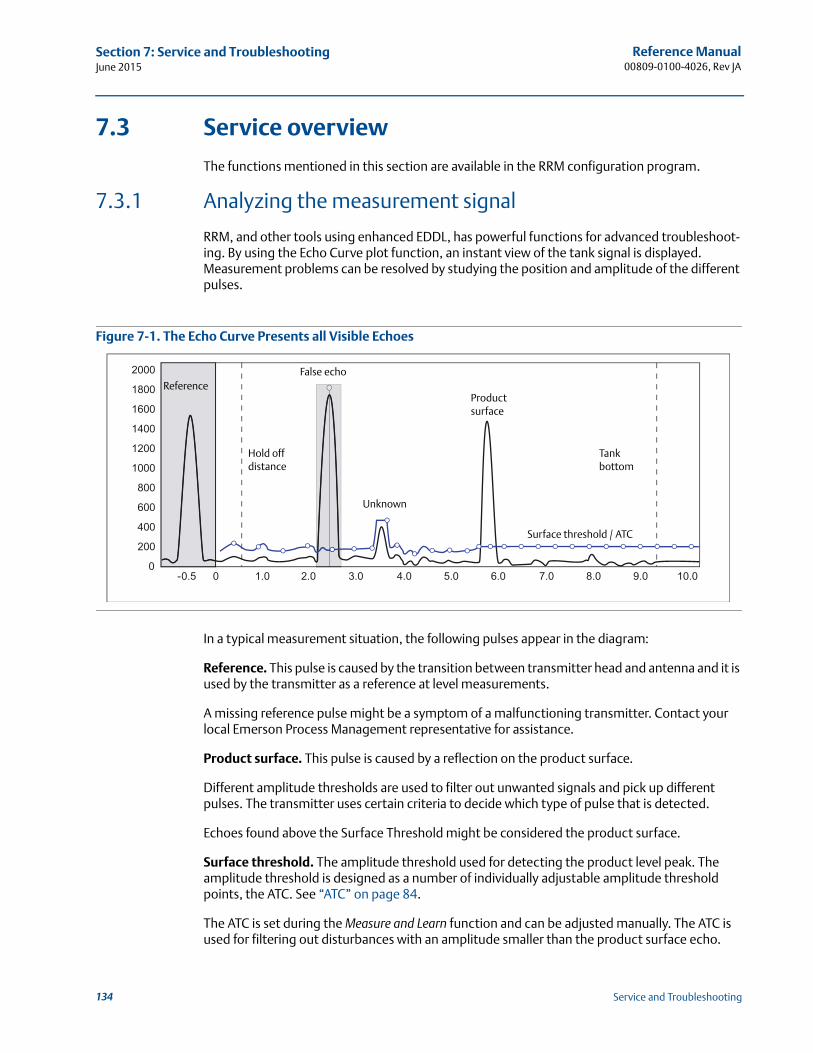
Reference Manual00809-0100-4026, Rev JA
Section 7: Service and TroubleshootingJune 2015
7.3 Service overview
The functions mentioned in this section are available in the RRM configuration program.
7.3.1 Analyzing the measurement signal
RRM, and other tools using enhanced EDDL, has powerful functions for advanced troubleshoot-ing. By using the Echo Curve plot function, an instant view of the tank signal is displayed. Measurement problems can be resolved by studying the position and amplitude of the different pulses.
Figure 7-1. The Echo Curve Presents all Visible Echoes
In a typical measurement situation, the following pulses appear in the diagram:
Reference. This pulse is caused by the transition between transmitter head and antenna and it is used by the transmitter as a reference at level measurements.
A missing reference pulse might be a symptom of a malfunctioning transmitter. Contact your local Emerson Process Management representative for assistance.
Product surface. This pulse is caused by a reflection on the product surface.
Different amplitude thresholds are used to filter out unwanted signals and pick up different pulses. The transmitter uses certain criteria to decide which type of pulse that is detected.
Echoes found above the Surface Threshold might be considered the product surface.
Surface threshold. The amplitude threshold used for detecting the product level peak. The amplitude threshold is designed as a number of individually adjustable amplitude threshold points, the ATC. See “ATC” on page 84.
The ATC is set during the Measure and Learn function and can be adjusted manually. The ATC is used for filtering out disturbances with an amplitude smaller than the product surface echo.
ReferenceProduct surface
Unknown
Hold off distance
Tank bottom
False echo
Surface threshold / ATC
134 Service and Troubleshooting
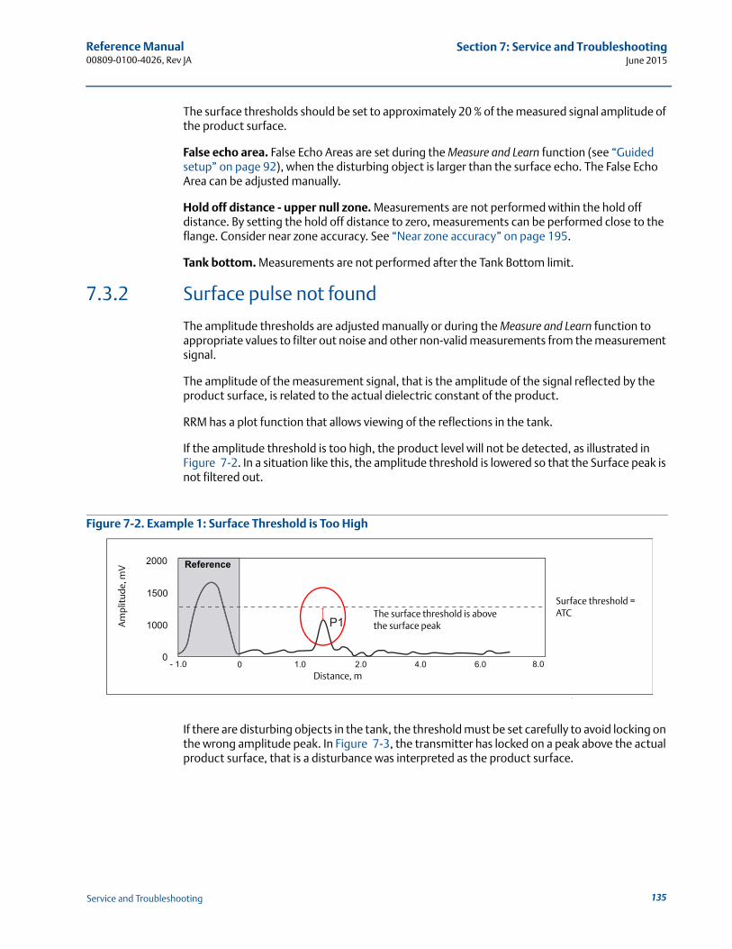
Reference Manual 00809-0100-4026, Rev JA
Section 7: Service and TroubleshootingJune 2015
The surface thresholds should be set to approximately 20 % of the measured signal amplitude of the product surface.
False echo area. False Echo Areas are set during the Measure and Learn function (see “Guided setup” on page 92), when the disturbing object is larger than the surface echo. The False Echo Area can be adjusted manually.
Hold off distance - upper null zone. Measurements are not performed within the hold off distance. By setting the hold off distance to zero, measurements can be performed close to the flange. Consider near zone accuracy. See “Near zone accuracy” on page 195.
Tank bottom. Measurements are not performed after the Tank Bottom limit.
7.3.2 Surface pulse not found
The amplitude thresholds are adjusted manually or during the Measure and Learn function to appropriate values to filter out noise and other non-valid measurements from the measurement signal.
The amplitude of the measurement signal, that is the amplitude of the signal reflected by the product surface, is related to the actual dielectric constant of the product.
RRM has a plot function that allows viewing of the reflections in the tank.
If the amplitude threshold is too high, the product level will not be detected, as illustrated in Figure 7-2. In a situation like this, the amplitude threshold is lowered so that the Surface peak is not filtered out.
Figure 7-2. Example 1: Surface Threshold is Too High
If there are disturbing objects in the tank, the threshold must be set carefully to avoid locking on the wrong amplitude peak. In Figure 7-3, the transmitter has locked on a peak above the actual product surface, that is a disturbance was interpreted as the product surface.
Am
plit
ude,
mV
The surface threshold is above the surface peak
Surface threshold =ATC
Distance, m
Reference
135Service and Troubleshooting
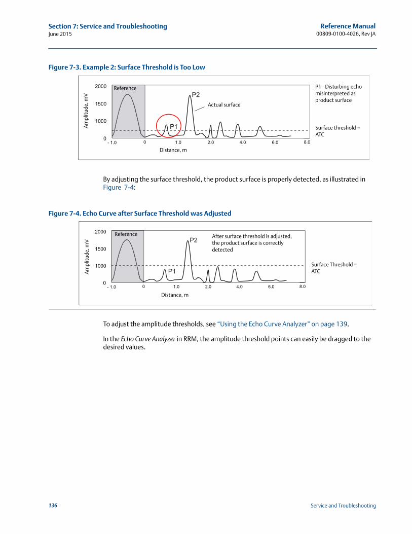
Reference Manual00809-0100-4026, Rev JA
Section 7: Service and TroubleshootingJune 2015
Figure 7-3. Example 2: Surface Threshold is Too Low
By adjusting the surface threshold, the product surface is properly detected, as illustrated in Figure 7-4:
Figure 7-4. Echo Curve after Surface Threshold was Adjusted
To adjust the amplitude thresholds, see “Using the Echo Curve Analyzer” on page 139.
In the Echo Curve Analyzer in RRM, the amplitude threshold points can easily be dragged to the desired values.
Am
plit
ude,
mV
Actual surface
Surface threshold =ATC
Distance, m
P1 - Disturbing echo misinterpreted as product surface
ReferenceA
mpl
itud
e, m
V
Distance, m
After surface threshold is adjusted, the product surface is correctly detected
Surface Threshold =ATC
Reference
136 Service and Troubleshooting
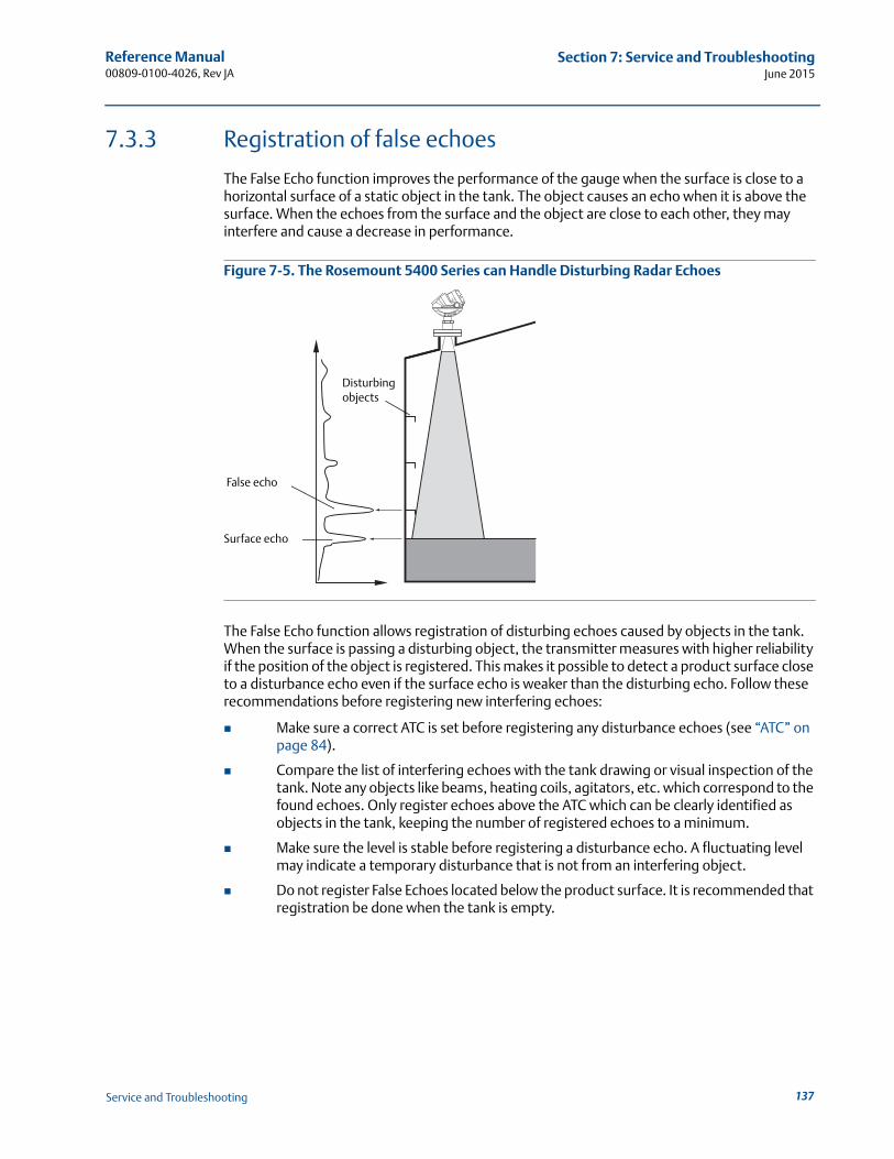
Reference Manual 00809-0100-4026, Rev JA
Section 7: Service and TroubleshootingJune 2015
7.3.3 Registration of false echoes
The False Echo function improves the performance of the gauge when the surface is close to a horizontal surface of a static object in the tank. The object causes an echo when it is above the surface. When the echoes from the surface and the object are close to each other, they may interfere and cause a decrease in performance.
Figure 7-5. The Rosemount 5400 Series can Handle Disturbing Radar Echoes
The False Echo function allows registration of disturbing echoes caused by objects in the tank. When the surface is passing a disturbing object, the transmitter measures with higher reliability if the position of the object is registered. This makes it possible to detect a product surface close to a disturbance echo even if the surface echo is weaker than the disturbing echo. Follow these recommendations before registering new interfering echoes:
Make sure a correct ATC is set before registering any disturbance echoes (see “ATC” on page 84).
Compare the list of interfering echoes with the tank drawing or visual inspection of the tank. Note any objects like beams, heating coils, agitators, etc. which correspond to the found echoes. Only register echoes above the ATC which can be clearly identified as objects in the tank, keeping the number of registered echoes to a minimum.
Make sure the level is stable before registering a disturbance echo. A fluctuating level may indicate a temporary disturbance that is not from an interfering object.
Do not register False Echoes located below the product surface. It is recommended that registration be done when the tank is empty.
False echo
Surface echo
Disturbing objects
137Service and Troubleshooting
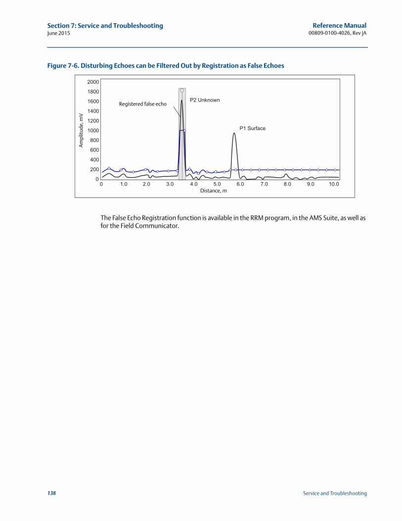
Reference Manual00809-0100-4026, Rev JA
Section 7: Service and TroubleshootingJune 2015
Figure 7-6. Disturbing Echoes can be Filtered Out by Registration as False Echoes
The False Echo Registration function is available in the RRM program, in the AMS Suite, as well as for the Field Communicator.
Registered false echo
Am
plit
ude,
mV
Distance, m
138 Service and Troubleshooting
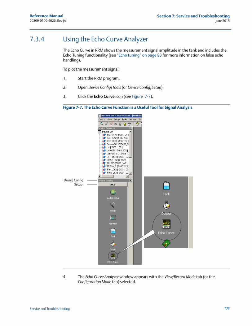
Reference Manual 00809-0100-4026, Rev JA
Section 7: Service and TroubleshootingJune 2015
7.3.4 Using the Echo Curve Analyzer
The Echo Curve in RRM shows the measurement signal amplitude in the tank and includes the Echo Tuning functionality (see “Echo tuning” on page 83 for more information on false echo handling).
To plot the measurement signal:
1. Start the RRM program.
2. Open Device Config/Tools (or Device Config/Setup).
3. Click the Echo Curve icon (see Figure 7-7).
Figure 7-7. The Echo Curve Function is a Useful Tool for Signal Analysis
4. The Echo Curve Analyzer window appears with the View/Record Mode tab (or the Configuration Mode tab) selected.
Device ConfigSetup
139Service and Troubleshooting
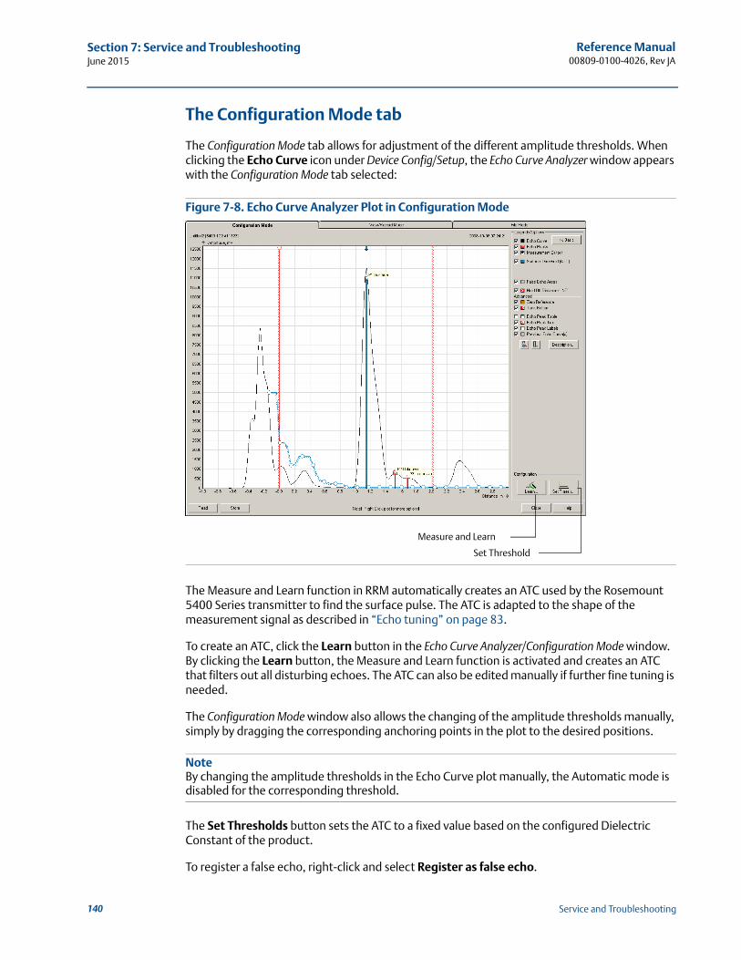
Reference Manual00809-0100-4026, Rev JA
Section 7: Service and TroubleshootingJune 2015
The Configuration Mode tab
The Configuration Mode tab allows for adjustment of the different amplitude thresholds. When clicking the Echo Curve icon under Device Config/Setup, the Echo Curve Analyzer window appears with the Configuration Mode tab selected:
Figure 7-8. Echo Curve Analyzer Plot in Configuration Mode
The Measure and Learn function in RRM automatically creates an ATC used by the Rosemount 5400 Series transmitter to find the surface pulse. The ATC is adapted to the shape of the measurement signal as described in “Echo tuning” on page 83.
To create an ATC, click the Learn button in the Echo Curve Analyzer/Configuration Mode window. By clicking the Learn button, the Measure and Learn function is activated and creates an ATC that filters out all disturbing echoes. The ATC can also be edited manually if further fine tuning is needed.
The Configuration Mode window also allows the changing of the amplitude thresholds manually, simply by dragging the corresponding anchoring points in the plot to the desired positions.
NoteBy changing the amplitude thresholds in the Echo Curve plot manually, the Automatic mode is disabled for the corresponding threshold.
The Set Thresholds button sets the ATC to a fixed value based on the configured Dielectric Constant of the product.
To register a false echo, right-click and select Register as false echo.
Set Threshold
Measure and Learn
140 Service and Troubleshooting
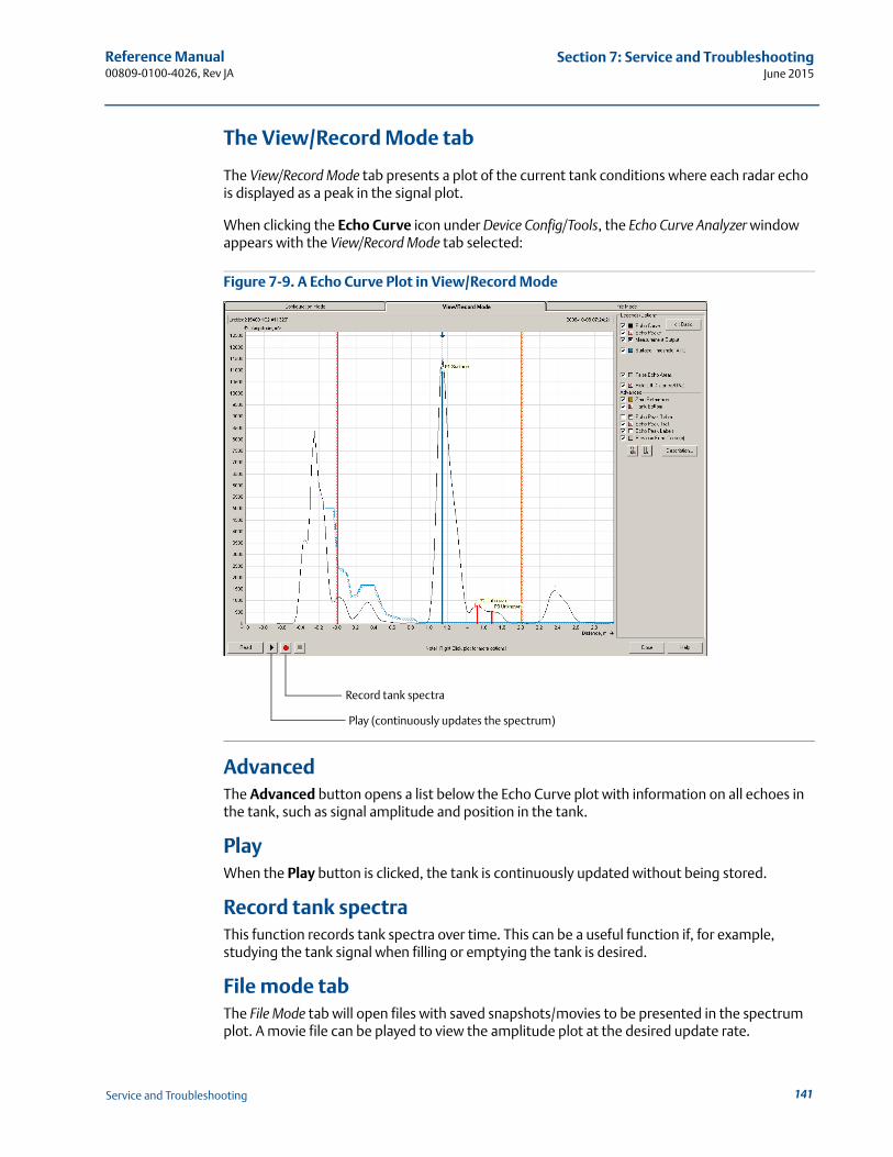
Reference Manual 00809-0100-4026, Rev JA
Section 7: Service and TroubleshootingJune 2015
The View/Record Mode tab
The View/Record Mode tab presents a plot of the current tank conditions where each radar echo is displayed as a peak in the signal plot.
When clicking the Echo Curve icon under Device Config/Tools, the Echo Curve Analyzer window appears with the View/Record Mode tab selected:
Figure 7-9. A Echo Curve Plot in View/Record Mode
AdvancedThe Advanced button opens a list below the Echo Curve plot with information on all echoes in the tank, such as signal amplitude and position in the tank.
PlayWhen the Play button is clicked, the tank is continuously updated without being stored.
Record tank spectraThis function records tank spectra over time. This can be a useful function if, for example, studying the tank signal when filling or emptying the tank is desired.
File mode tabThe File Mode tab will open files with saved snapshots/movies to be presented in the spectrum plot. A movie file can be played to view the amplitude plot at the desired update rate.
Record tank spectra
Play (continuously updates the spectrum)
141Service and Troubleshooting
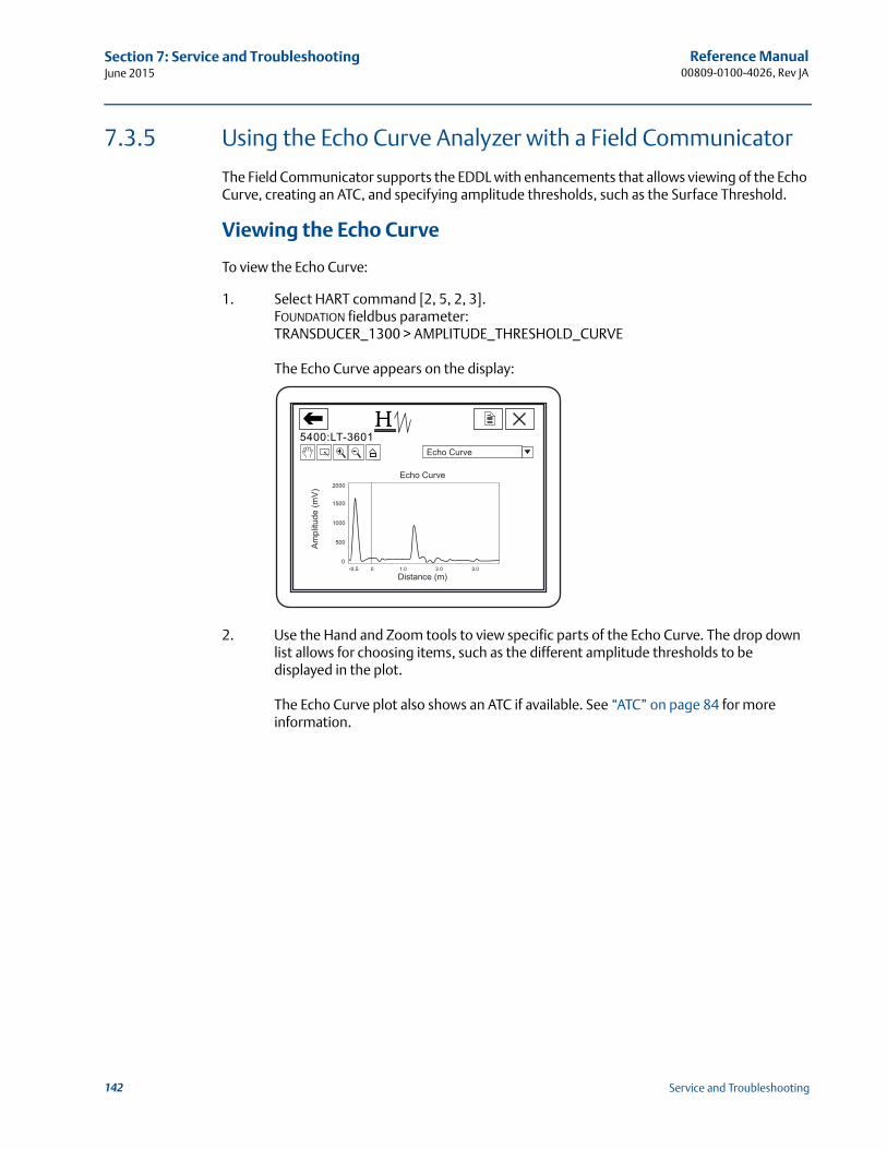
Reference Manual00809-0100-4026, Rev JA
Section 7: Service and TroubleshootingJune 2015
7.3.5 Using the Echo Curve Analyzer with a Field Communicator
The Field Communicator supports the EDDL with enhancements that allows viewing of the Echo Curve, creating an ATC, and specifying amplitude thresholds, such as the Surface Threshold.
Viewing the Echo Curve
To view the Echo Curve:
1. Select HART command [2, 5, 2, 3].FOUNDATION fieldbus parameter:TRANSDUCER_1300 > AMPLITUDE_THRESHOLD_CURVE
The Echo Curve appears on the display:
2. Use the Hand and Zoom tools to view specific parts of the Echo Curve. The drop down list allows for choosing items, such as the different amplitude thresholds to be displayed in the plot.
The Echo Curve plot also shows an ATC if available. See “ATC” on page 84 for more information.
142 Service and Troubleshooting
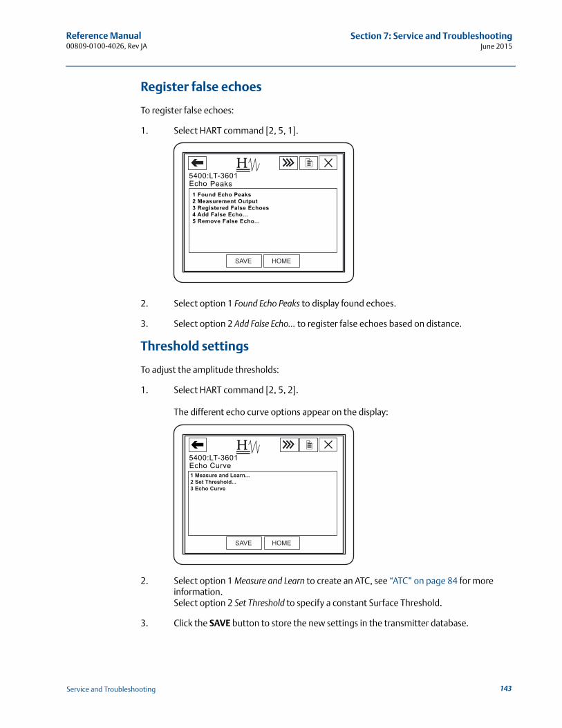
Reference Manual 00809-0100-4026, Rev JA
Section 7: Service and TroubleshootingJune 2015
Register false echoes
To register false echoes:
1. Select HART command [2, 5, 1].
2. Select option 1 Found Echo Peaks to display found echoes.
3. Select option 2 Add False Echo... to register false echoes based on distance.
Threshold settings
To adjust the amplitude thresholds:
1. Select HART command [2, 5, 2].
The different echo curve options appear on the display:
2. Select option 1 Measure and Learn to create an ATC, see “ATC” on page 84 for more information.Select option 2 Set Threshold to specify a constant Surface Threshold.
3. Click the SAVE button to store the new settings in the transmitter database.
1 Found Echo Peaks2 Measurement Output3 Registered False Echoes4 Add False Echo...5 Remove False Echo...
Peaks
143Service and Troubleshooting
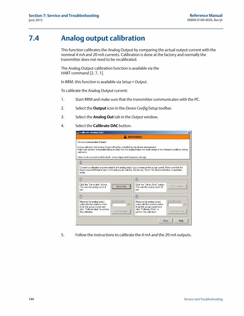
Reference Manual00809-0100-4026, Rev JA
Section 7: Service and TroubleshootingJune 2015
7.4 Analog output calibration
This function calibrates the Analog Output by comparing the actual output current with the nominal 4 mA and 20 mA currents. Calibration is done at the factory and normally the transmitter does not need to be recalibrated.
The Analog Output calibration function is available via theHART command [2, 7, 1].
In RRM, this function is available via Setup > Output.
To calibrate the Analog Output current:
1. Start RRM and make sure that the transmitter communicates with the PC.
2. Select the Output icon in the Device Config/Setup toolbar.
3. Select the Analog Out tab in the Output window.
4. Select the Calibrate DAC button.
5. Follow the instructions to calibrate the 4 mA and the 20 mA outputs.
144 Service and Troubleshooting
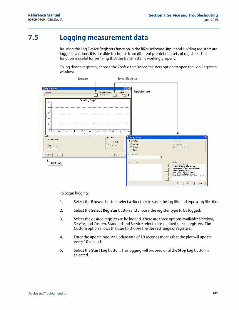
Reference Manual 00809-0100-4026, Rev JA
Section 7: Service and TroubleshootingJune 2015
7.5 Logging measurement data
By using the Log Device Registers function in the RRM software, Input and Holding registers are logged over time. It is possible to choose from different pre-defined sets of registers. This function is useful for verifying that the transmitter is working properly.
To log device registers, choose the Tools > Log Device Registers option to open the Log Registers window:
To begin logging:
1. Select the Browse button, select a directory to store the log file, and type a log file title.
2. Select the Select Register button and choose the register type to be logged.
3. Select the desired registers to be logged. There are three options available: Standard, Service, and Custom. Standard and Service refer to pre-defined sets of registers. The Custom option allows the user to choose the desired range of registers.
4. Enter the update rate. An update rate of 10 seconds means that the plot will update every 10 seconds.
5. Select the Start Log button. The logging will proceed until the Stop Log button is selected.
Start Log
Browse Select Register
Update rate
145Service and Troubleshooting
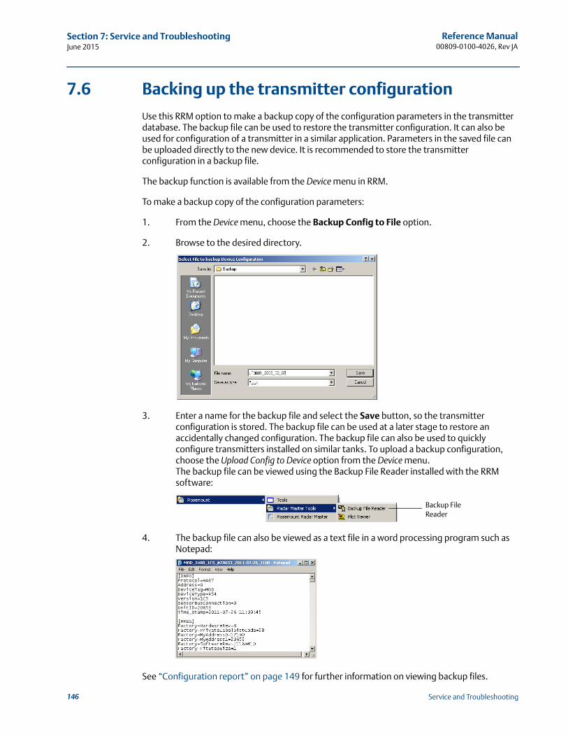
Reference Manual00809-0100-4026, Rev JA
Section 7: Service and TroubleshootingJune 2015
7.6 Backing up the transmitter configuration
Use this RRM option to make a backup copy of the configuration parameters in the transmitter database. The backup file can be used to restore the transmitter configuration. It can also be used for configuration of a transmitter in a similar application. Parameters in the saved file can be uploaded directly to the new device. It is recommended to store the transmitter configuration in a backup file.
The backup function is available from the Device menu in RRM.
To make a backup copy of the configuration parameters:
1. From the Device menu, choose the Backup Config to File option.
2. Browse to the desired directory.
3. Enter a name for the backup file and select the Save button, so the transmitter configuration is stored. The backup file can be used at a later stage to restore an accidentally changed configuration. The backup file can also be used to quickly configure transmitters installed on similar tanks. To upload a backup configuration, choose the Upload Config to Device option from the Device menu.The backup file can be viewed using the Backup File Reader installed with the RRM software:
4. The backup file can also be viewed as a text file in a word processing program such as Notepad:
See “Configuration report” on page 149 for further information on viewing backup files.
Backup File Reader
146 Service and Troubleshooting
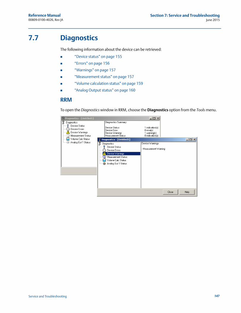
Reference Manual 00809-0100-4026, Rev JA
Section 7: Service and TroubleshootingJune 2015
7.7 Diagnostics
The following information about the device can be retrieved:
“Device status” on page 155
“Errors” on page 156
“Warnings” on page 157
“Measurement status” on page 157
“Volume calculation status” on page 159
“Analog Output status” on page 160
RRM
To open the Diagnostics window in RRM, choose the Diagnostics option from the Tools menu.
147Service and Troubleshooting
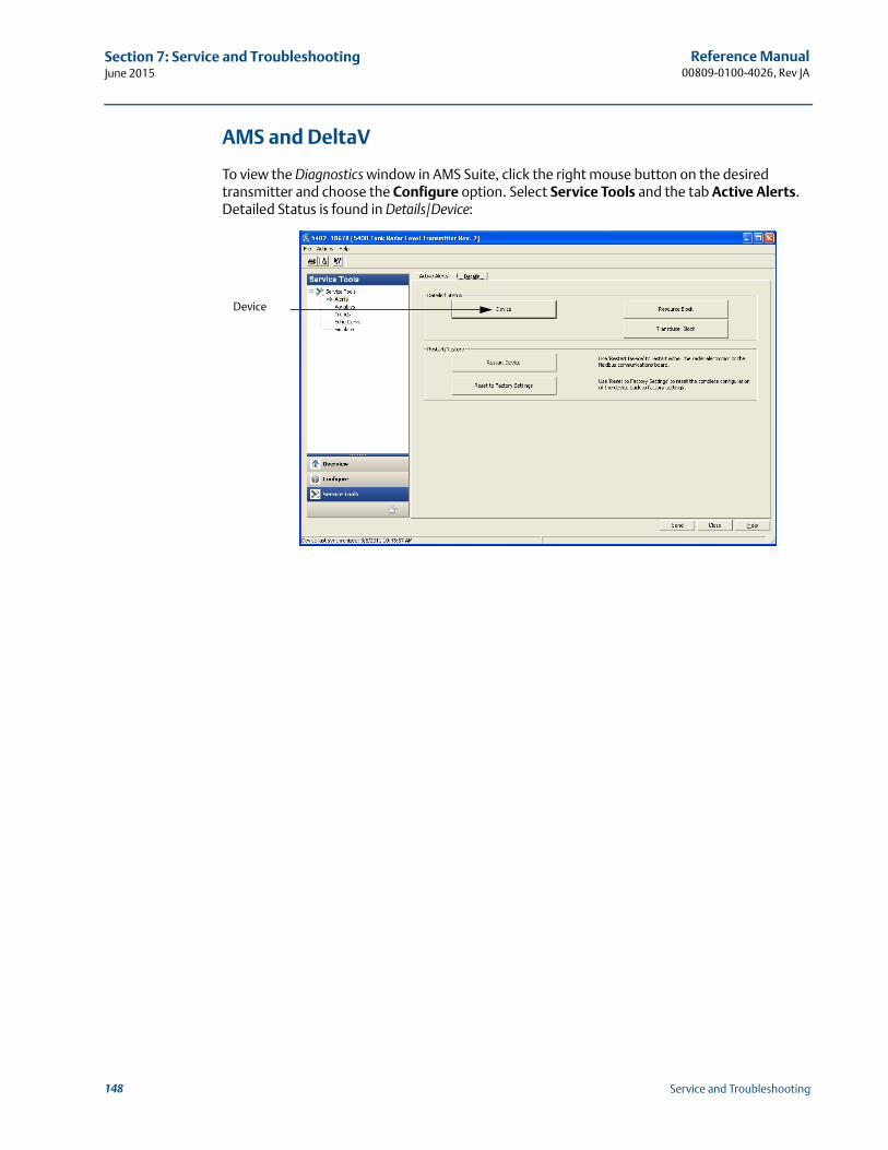
Reference Manual00809-0100-4026, Rev JA
Section 7: Service and TroubleshootingJune 2015
AMS and DeltaV
To view the Diagnostics window in AMS Suite, click the right mouse button on the desired transmitter and choose the Configure option. Select Service Tools and the tab Active Alerts. Detailed Status is found in Details/Device:
Device
148 Service and Troubleshooting
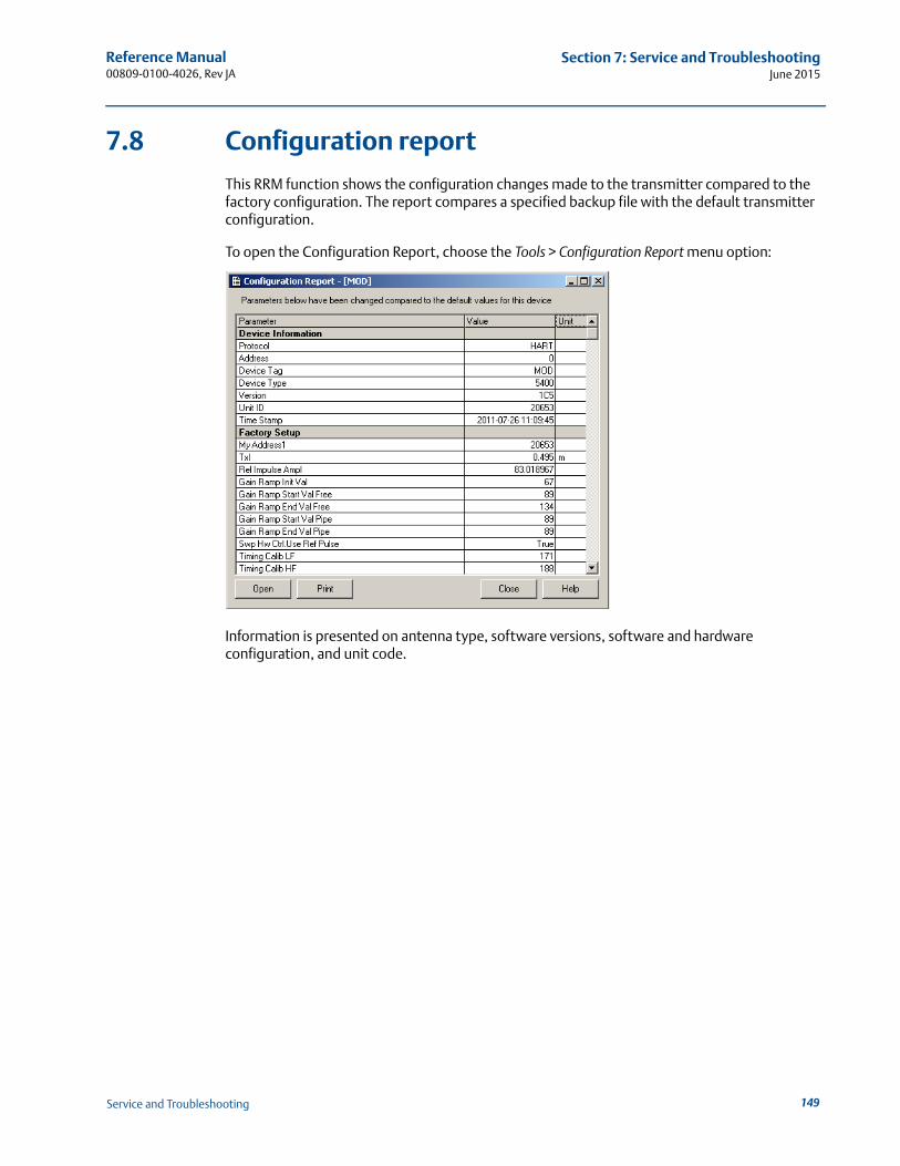
Reference Manual 00809-0100-4026, Rev JA
Section 7: Service and TroubleshootingJune 2015
7.8 Configuration report
This RRM function shows the configuration changes made to the transmitter compared to the factory configuration. The report compares a specified backup file with the default transmitter configuration.
To open the Configuration Report, choose the Tools > Configuration Report menu option:
Information is presented on antenna type, software versions, software and hardware configuration, and unit code.
149Service and Troubleshooting
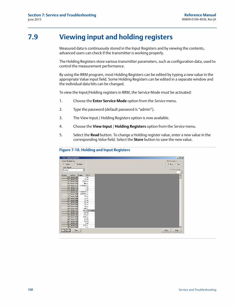
Reference Manual00809-0100-4026, Rev JA
Section 7: Service and TroubleshootingJune 2015
7.9 Viewing input and holding registers
Measured data is continuously stored in the Input Registers and by viewing the contents, advanced users can check if the transmitter is working properly.
The Holding Registers store various transmitter parameters, such as configuration data, used to control the measurement performance.
By using the RRM program, most Holding Registers can be edited by typing a new value in the appropriate Value input field. Some Holding Registers can be edited in a separate window and the individual data bits can be changed.
To view the Input/Holding registers in RRM, the Service Mode must be activated:
1. Choose the Enter Service Mode option from the Service menu.
2. Type the password (default password is “admin”).
3. The View Input / Holding Registers option is now available.
4. Choose the View Input / Holding Registers option from the Service menu.
5. Select the Read button. To change a Holding register value, enter a new value in the corresponding Value field. Select the Store button to save the new value.
Figure 7-10. Holding and Input Registers
150 Service and Troubleshooting
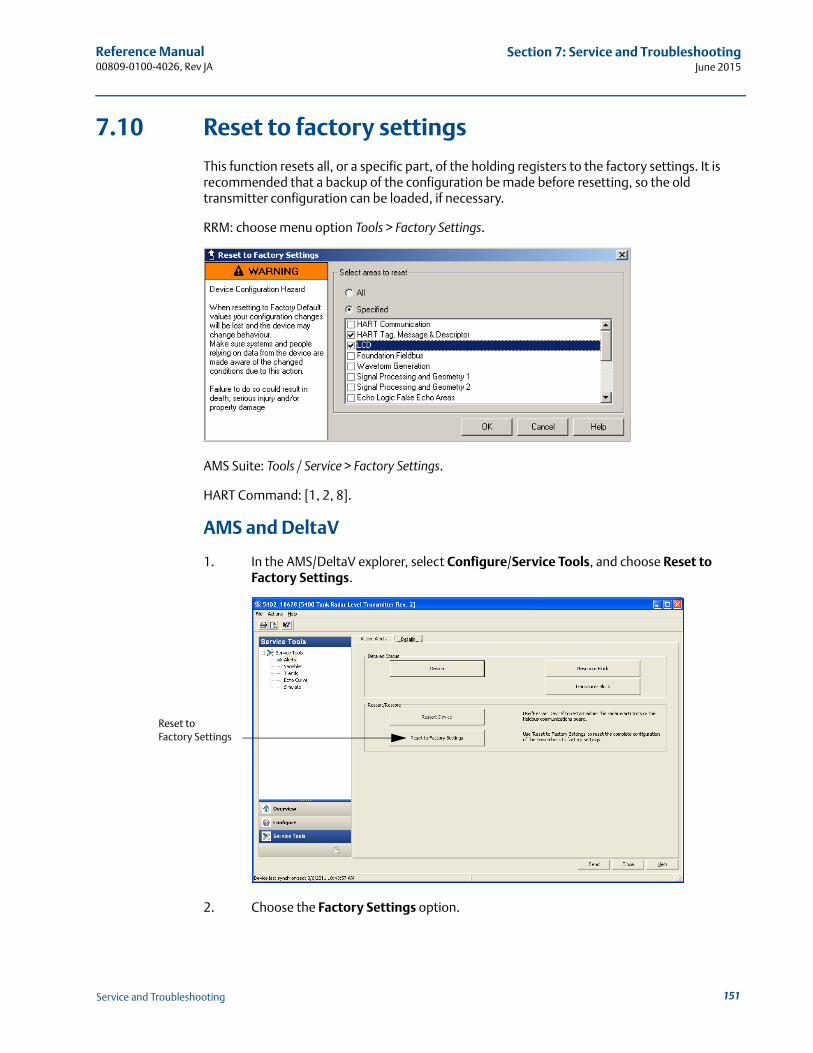
Reference Manual 00809-0100-4026, Rev JA
Section 7: Service and TroubleshootingJune 2015
7.10 Reset to factory settings
This function resets all, or a specific part, of the holding registers to the factory settings. It is recommended that a backup of the configuration be made before resetting, so the old transmitter configuration can be loaded, if necessary.
RRM: choose menu option Tools > Factory Settings.
AMS Suite: Tools / Service > Factory Settings.
HART Command: [1, 2, 8].
AMS and DeltaV
1. In the AMS/DeltaV explorer, select Configure/Service Tools, and choose Reset to Factory Settings.
2. Choose the Factory Settings option.
Reset to Factory Settings
151Service and Troubleshooting
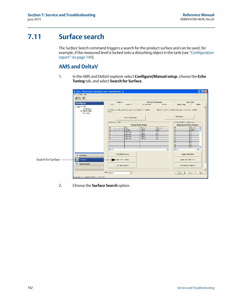
Reference Manual00809-0100-4026, Rev JA
Section 7: Service and TroubleshootingJune 2015
7.11 Surface search
The Surface Search command triggers a search for the product surface and can be used, for example, if the measured level is locked onto a disturbing object in the tank (see “Configuration report” on page 149).
AMS and DeltaV
1. In the AMS and DeltaV explorer select Configure/Manual setup, choose the Echo Tuning tab, and select Search for Surface.
2. Choose the Surface Search option.
Search for Surface
152 Service and Troubleshooting
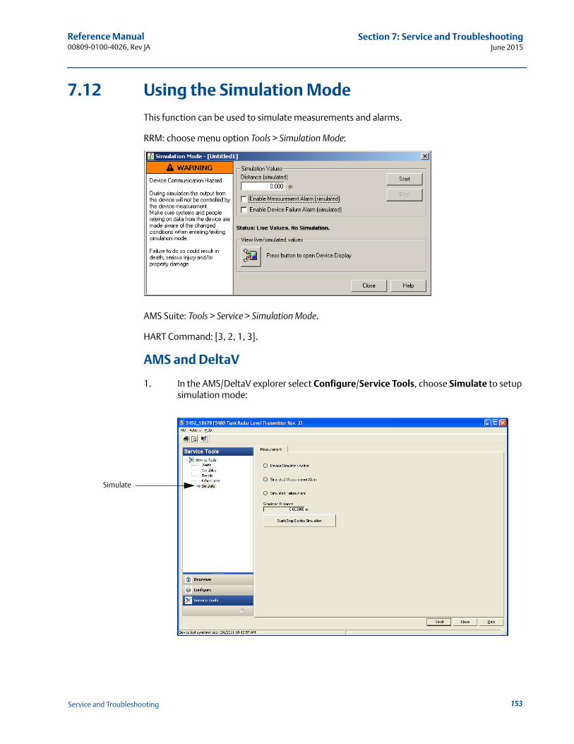
Reference Manual 00809-0100-4026, Rev JA
Section 7: Service and TroubleshootingJune 2015
7.12 Using the Simulation Mode
This function can be used to simulate measurements and alarms.
RRM: choose menu option Tools > Simulation Mode:
AMS Suite: Tools > Service > Simulation Mode.
HART Command: [3, 2, 1, 3].
AMS and DeltaV
1. In the AMS/DeltaV explorer select Configure/Service Tools, choose Simulate to setup simulation mode:
Simulate
153Service and Troubleshooting
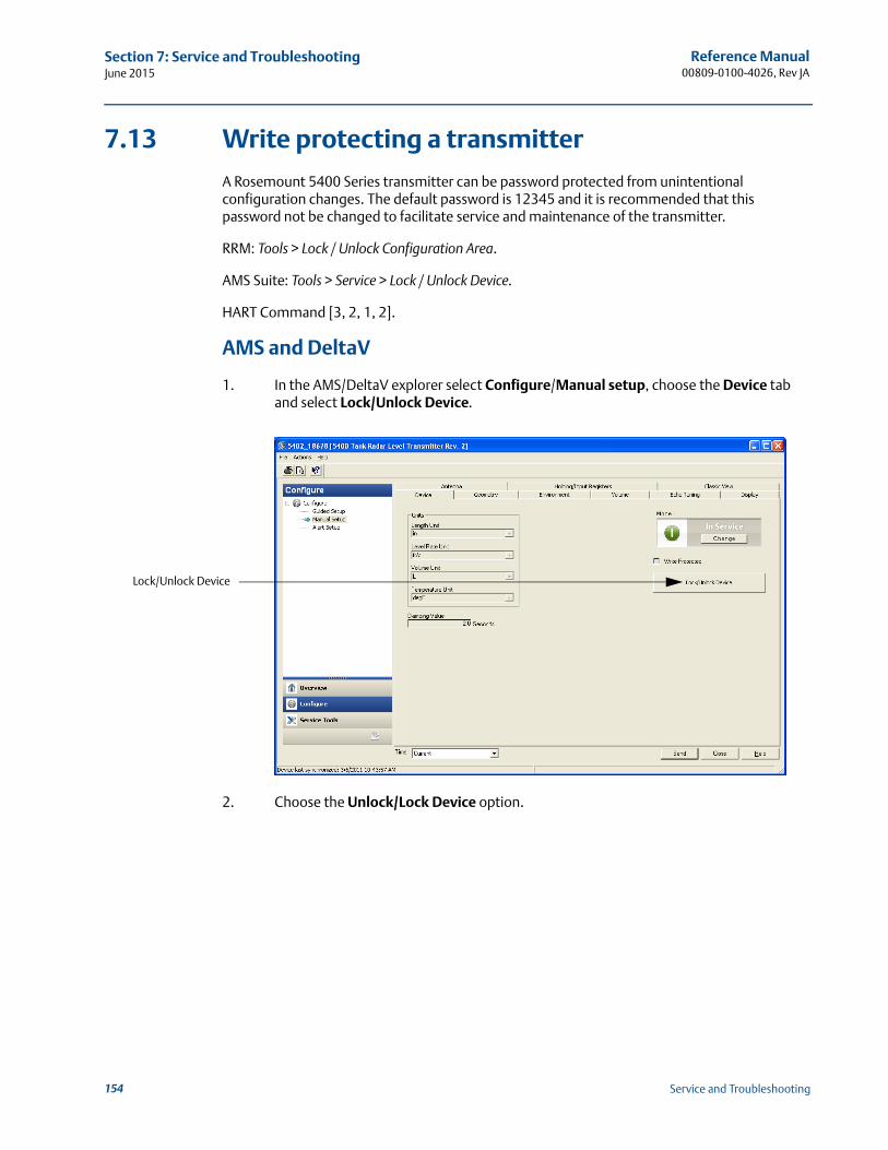
Reference Manual00809-0100-4026, Rev JA
Section 7: Service and TroubleshootingJune 2015
7.13 Write protecting a transmitter
A Rosemount 5400 Series transmitter can be password protected from unintentional configuration changes. The default password is 12345 and it is recommended that this password not be changed to facilitate service and maintenance of the transmitter.
RRM: Tools > Lock / Unlock Configuration Area.
AMS Suite: Tools > Service > Lock / Unlock Device.
HART Command [3, 2, 1, 2].
AMS and DeltaV
1. In the AMS/DeltaV explorer select Configure/Manual setup, choose the Device tab and select Lock/Unlock Device.
2. Choose the Unlock/Lock Device option.
Lock/Unlock Device
154 Service and Troubleshooting
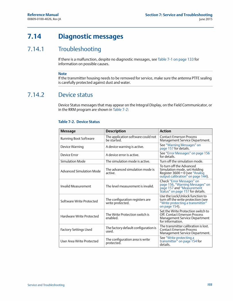
Reference Manual 00809-0100-4026, Rev JA
Section 7: Service and TroubleshootingJune 2015
7.14 Diagnostic messages
7.14.1 Troubleshooting
If there is a malfunction, despite no diagnostic messages, see Table 7-1 on page 133 for information on possible causes.
NoteIf the transmitter housing needs to be removed for service, make sure the antenna PTFE sealing is carefully protected against dust and water.
7.14.2 Device status
Device Status messages that may appear on the Integral Display, on the Field Communicator, or in the RRM program are shown in Table 7-2:
Table 7-2. Device Status
Message Description Action
Running Boot Software The application software could not be started.
Contact Emerson Process Management Service Department.
Device Warning A device warning is active. See “Warning Messages” on page 157 for details.
Device Error A device error is active. See “Error Messages” on page 156 for details.
Simulation Mode The simulation mode is active. Turn off the simulation mode.
Advanced Simulation Mode The advanced simulation mode is active.
To turn off the Advanced Simulation mode, set Holding Register 3600 = 0 (see “Analog output calibration” on page 144).
Invalid Measurement The level measurement is invalid.
Check “Error Messages” on page 156, “Warning Messages” on page 157 and “Measurement Status” on page 157 for details.
Software Write Protected The configuration registers are write protected.
Use the Lock/Unlock function to turn off the write protection (see “Write protecting a transmitter” on page 154).
Hardware Write Protected The Write Protection switch is enabled.
Set the Write Protection switch to Off. Contact Emerson Process Management Service Department for information.
Factory Settings Used The factory default configuration is used.
The transmitter calibration is lost. Contact Emerson Process Management Service Department.
User Area Write Protected The configuration area is write protected.
See “Write protecting a transmitter” on page 154 for details.
155Service and Troubleshooting
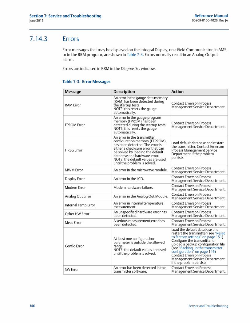
Reference Manual00809-0100-4026, Rev JA
Section 7: Service and TroubleshootingJune 2015
7.14.3 Errors
Error messages that may be displayed on the Integral Display, on a Field Communicator, in AMS, or in the RRM program, are shown in Table 7-3. Errors normally result in an Analog Output alarm.
Errors are indicated in RRM in the Diagnostics window.
Table 7-3. Error Messages
Message Description Action
RAM Error
An error in the gauge data memory (RAM) has been detected during the startup tests. NOTE: this resets the gauge automatically.
Contact Emerson Process Management Service Department.
FPROM Error
An error in the gauge program memory (FPROM) has been detected during the startup tests. NOTE: this resets the gauge automatically.
Contact Emerson Process Management Service Department.
HREG Error
An error in the transmitter configuration memory (EEPROM) has been detected. The error is either a checksum error that can be solved by loading the default database or a hardware error.NOTE: the default values are used until the problem is solved.
Load default database and restart the transmitter. Contact Emerson Process Management Service Department if the problem persists.
MWM Error An error in the microwave module. Contact Emerson Process Management Service Department.
Display Error An error in the LCD. Contact Emerson Process Management Service Department.
Modem Error Modem hardware failure. Contact Emerson Process Management Service Department.
Analog Out Error An error in the Analog Out Module. Contact Emerson Process Management Service Department.
Internal Temp Error An error in internal temperature measurement.
Contact Emerson Process Management Service Department.
Other HW Error An unspecified hardware error has been detected.
Contact Emerson Process Management Service Department.
Meas Error A serious measurement error has been detected.
Contact Emerson Process Management Service Department.
Config Error
At least one configuration parameter is outside the allowed range. NOTE: the default values are used until the problem is solved.
Load the default database and restart the transmitter (see “Reset to factory settings” on page 151)Configure the transmitter or upload a backup configuration file (see “Backing up the transmitter configuration” on page 146)Contact Emerson Process Management Service Department if the problem persists
SW Error An error has been detected in the transmitter software.
Contact Emerson Process Management Service Department.
156 Service and Troubleshooting
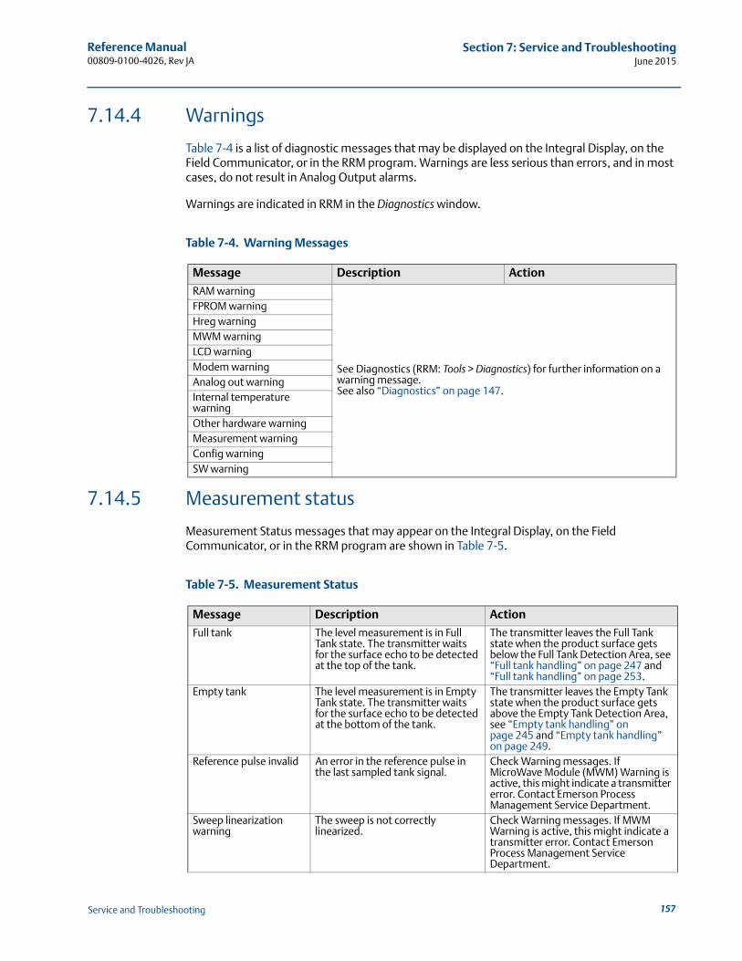
Reference Manual 00809-0100-4026, Rev JA
Section 7: Service and TroubleshootingJune 2015
7.14.4 Warnings
Table 7-4 is a list of diagnostic messages that may be displayed on the Integral Display, on the Field Communicator, or in the RRM program. Warnings are less serious than errors, and in most cases, do not result in Analog Output alarms.
Warnings are indicated in RRM in the Diagnostics window.
Table 7-4. Warning Messages
7.14.5 Measurement status
Measurement Status messages that may appear on the Integral Display, on the Field Communicator, or in the RRM program are shown in Table 7-5.
Table 7-5. Measurement Status
Message Description Action
RAM warning
See Diagnostics (RRM: Tools > Diagnostics) for further information on a warning message. See also “Diagnostics” on page 147.
FPROM warningHreg warningMWM warningLCD warningModem warningAnalog out warningInternal temperature warningOther hardware warningMeasurement warningConfig warningSW warning
Message Description Action
Full tank The level measurement is in Full Tank state. The transmitter waits for the surface echo to be detected at the top of the tank.
The transmitter leaves the Full Tank state when the product surface gets below the Full Tank Detection Area, see “Full tank handling” on page 247 and “Full tank handling” on page 253.
Empty tank The level measurement is in Empty Tank state. The transmitter waits for the surface echo to be detected at the bottom of the tank.
The transmitter leaves the Empty Tank state when the product surface gets above the Empty Tank Detection Area, see “Empty tank handling” on page 245 and “Empty tank handling” on page 249.
Reference pulse invalid An error in the reference pulse in the last sampled tank signal.
Check Warning messages. If MicroWave Module (MWM) Warning is active, this might indicate a transmitter error. Contact Emerson Process Management Service Department.
Sweep linearization warning
The sweep is not correctly linearized.
Check Warning messages. If MWM Warning is active, this might indicate a transmitter error. Contact Emerson Process Management Service Department.
157Service and Troubleshooting
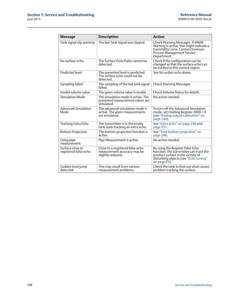
Reference Manual00809-0100-4026, Rev JA
Section 7: Service and TroubleshootingJune 2015
Tank signal clip warning The last Tank Signal was clipped. Check Warning Messages. If MWM Warning is active, this might indicate a transmitter error. Contact Emerson Process Management Service Department.
No surface echo The Surface Echo Pulse cannot be detected.
Check if the configuration can be changed so that the surface echo can be tracked in this current region.
Predicted level The presented level is predicted. The surface echo could not be detected.
See No surface echo above.
Sampling failed The sampling of the last tank signal failed.
Check Warning Messages.
Invalid volume value The given volume value is invalid. Check Volume Status for details.Simulation Mode The simulation mode is active. The
presented measurement values are simulated.
No action needed.
Advanced Simulation Mode
The advanced simulation mode is active. The given measurements are simulated.
To turn off the Advanced Simulation mode, set Holding Register 3600 = 0 (see “Analog output calibration” on page 144).
Tracking Extra Echo The transmitter is in the empty tank state tracking an extra echo.
See “Extra echo” on page 246 and page 251.
Bottom Projection The bottom projection function is active.
See “Tank bottom projection” on page 246.
Using pipe measurement
Pipe Measurement is active. No action needed.
Surface close to registered false echo.
Close to a registered false echo measurement accuracy may be slightly reduced.
By using the Register False Echo function, the transmitter can track the product surface in the vicinity of disturbing objects (see “Echo tuning” on page 83).
Sudden level jump detected.
This may result from various measurement problems.
Check the tank to find out what causes problem tracking the surface.
Message Description Action
158 Service and Troubleshooting
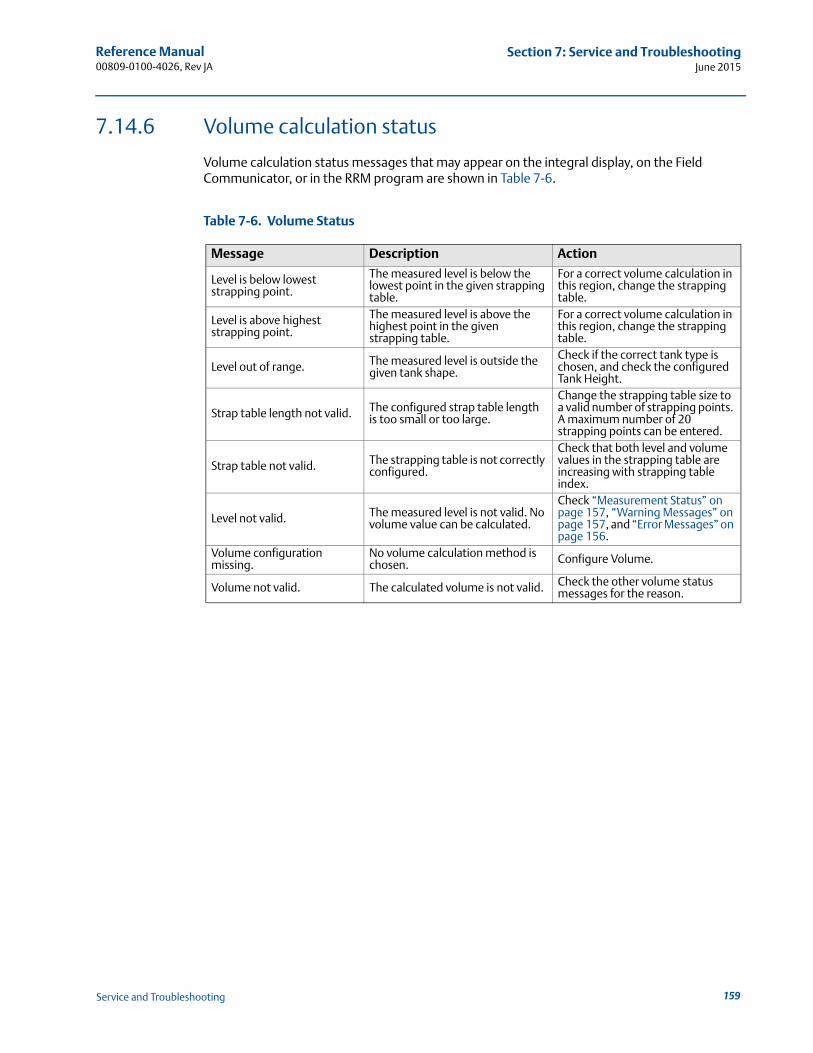
Reference Manual 00809-0100-4026, Rev JA
Section 7: Service and TroubleshootingJune 2015
7.14.6 Volume calculation status
Volume calculation status messages that may appear on the integral display, on the Field Communicator, or in the RRM program are shown in Table 7-6.
Table 7-6. Volume Status
Message Description Action
Level is below lowest strapping point.
The measured level is below the lowest point in the given strapping table.
For a correct volume calculation in this region, change the strapping table.
Level is above highest strapping point.
The measured level is above the highest point in the given strapping table.
For a correct volume calculation in this region, change the strapping table.
Level out of range. The measured level is outside the given tank shape.
Check if the correct tank type is chosen, and check the configured Tank Height.
Strap table length not valid. The configured strap table length is too small or too large.
Change the strapping table size to a valid number of strapping points. A maximum number of 20 strapping points can be entered.
Strap table not valid. The strapping table is not correctly configured.
Check that both level and volume values in the strapping table are increasing with strapping table index.
Level not valid. The measured level is not valid. No volume value can be calculated.
Check “Measurement Status” on page 157, “Warning Messages” on page 157, and “Error Messages” on page 156.
Volume configuration missing.
No volume calculation method is chosen. Configure Volume.
Volume not valid. The calculated volume is not valid. Check the other volume status messages for the reason.
159Service and Troubleshooting
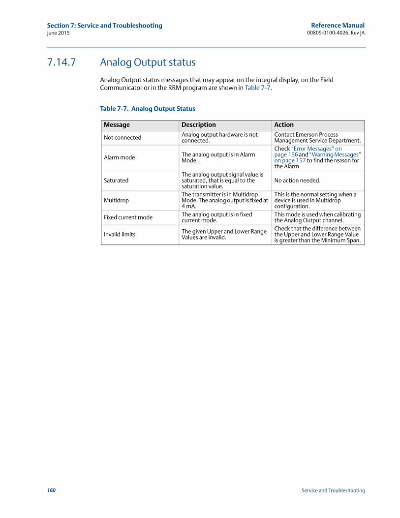
Reference Manual00809-0100-4026, Rev JA
Section 7: Service and TroubleshootingJune 2015
7.14.7 Analog Output status
Analog Output status messages that may appear on the integral display, on the Field Communicator or in the RRM program are shown in Table 7-7.
Table 7-7. Analog Output Status
Message Description Action
Not connected Analog output hardware is not connected.
Contact Emerson Process Management Service Department.
Alarm mode The analog output is in Alarm Mode.
Check “Error Messages” on page 156 and “Warning Messages” on page 157 to find the reason for the Alarm.
SaturatedThe analog output signal value is saturated, that is equal to the saturation value.
No action needed.
MultidropThe transmitter is in Multidrop Mode. The analog output is fixed at 4 mA.
This is the normal setting when a device is used in Multidrop configuration.
Fixed current mode The analog output is in fixed current mode.
This mode is used when calibrating the Analog Output channel.
Invalid limits The given Upper and Lower Range Values are invalid.
Check that the difference between the Upper and Lower Range Value is greater than the Minimum Span.
160 Service and Troubleshooting
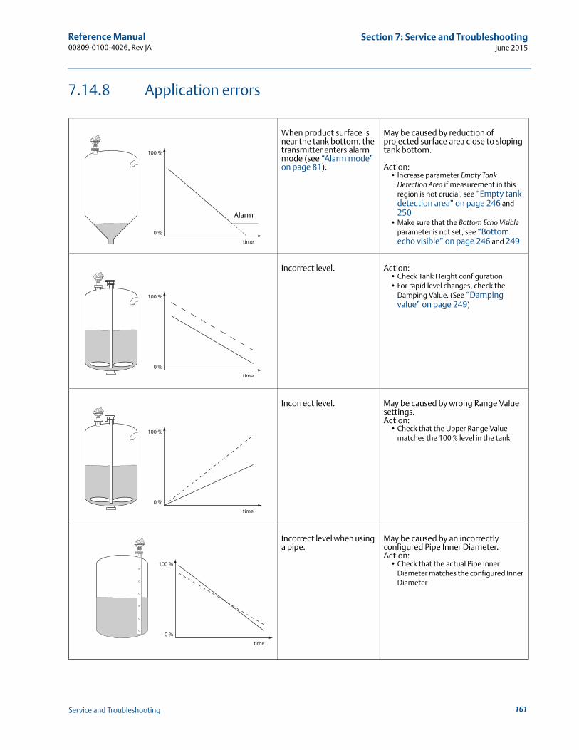
Reference Manual 00809-0100-4026, Rev JA
Section 7: Service and TroubleshootingJune 2015
7.14.8 Application errors
When product surface is near the tank bottom, the transmitter enters alarm mode (see “Alarm mode” on page 81).
May be caused by reduction of projected surface area close to sloping tank bottom.
Action:• Increase parameter Empty Tank
Detection Area if measurement in this region is not crucial, see “Empty tank detection area” on page 246 and 250
• Make sure that the Bottom Echo Visible parameter is not set, see “Bottom echo visible” on page 246 and 249
Incorrect level. Action:• Check Tank Height configuration• For rapid level changes, check the
Damping Value. (See “Damping value” on page 249)
Incorrect level. May be caused by wrong Range Value settings.Action:
• Check that the Upper Range Value matches the 100 % level in the tank
Incorrect level when using a pipe.
May be caused by an incorrectly configured Pipe Inner Diameter.Action:
• Check that the actual Pipe Inner Diameter matches the configured Inner Diameter
Alarm
161Service and Troubleshooting
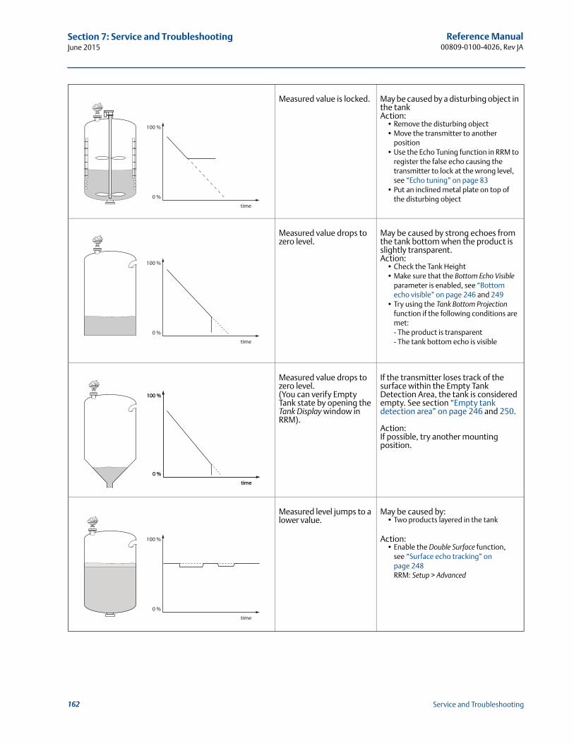
Reference Manual00809-0100-4026, Rev JA
Section 7: Service and TroubleshootingJune 2015
Measured value is locked. May be caused by a disturbing object in the tankAction:
• Remove the disturbing object • Move the transmitter to another
position• Use the Echo Tuning function in RRM to
register the false echo causing the transmitter to lock at the wrong level, see “Echo tuning” on page 83
• Put an inclined metal plate on top of the disturbing object
Measured value drops to zero level.
May be caused by strong echoes from the tank bottom when the product is slightly transparent.Action:
• Check the Tank Height• Make sure that the Bottom Echo Visible
parameter is enabled, see “Bottom echo visible” on page 246 and 249
• Try using the Tank Bottom Projection function if the following conditions are met:- The product is transparent- The tank bottom echo is visible
Measured value drops to zero level.(You can verify Empty Tank state by opening the Tank Display window in RRM).
If the transmitter loses track of the surface within the Empty Tank Detection Area, the tank is considered empty. See section “Empty tank detection area” on page 246 and 250.
Action: If possible, try another mounting position.
Measured level jumps to a lower value.
May be caused by:• Two products layered in the tank
Action:• Enable the Double Surface function,
see “Surface echo tracking” on page 248RRM: Setup > Advanced
162 Service and Troubleshooting
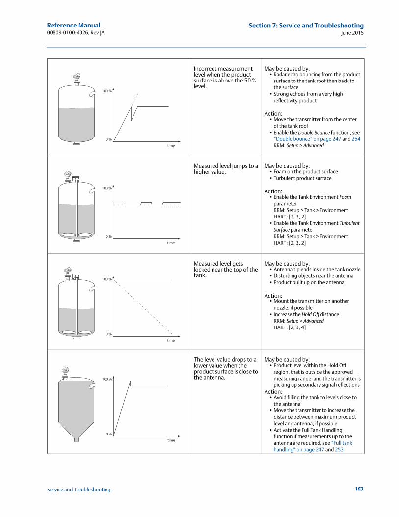
Reference Manual 00809-0100-4026, Rev JA
Section 7: Service and TroubleshootingJune 2015
Incorrect measurement level when the product surface is above the 50 % level.
May be caused by:• Radar echo bouncing from the product
surface to the tank roof then back to the surface
• Strong echoes from a very high reflectivity product
Action:• Move the transmitter from the center
of the tank roof• Enable the Double Bounce function, see
“Double bounce” on page 247 and 254RRM: Setup > Advanced
Measured level jumps to a higher value.
May be caused by:• Foam on the product surface• Turbulent product surface
Action:• Enable the Tank Environment Foam
parameterRRM: Setup > Tank > EnvironmentHART: [2, 3, 2]
• Enable the Tank Environment Turbulent Surface parameterRRM: Setup > Tank > EnvironmentHART: [2, 3, 2]
Measured level gets locked near the top of the tank.
May be caused by:• Antenna tip ends inside the tank nozzle• Disturbing objects near the antenna• Product built up on the antenna
Action:• Mount the transmitter on another
nozzle, if possible• Increase the Hold Off distance
RRM: Setup > AdvancedHART: [2, 3, 4]
The level value drops to a lower value when the product surface is close to the antenna.
May be caused by:• Product level within the Hold Off
region, that is outside the approved measuring range, and the transmitter is picking up secondary signal reflections
Action:• Avoid filling the tank to levels close to
the antenna• Move the transmitter to increase the
distance between maximum product level and antenna, if possible
• Activate the Full Tank Handling function if measurements up to the antenna are required, see “Full tank handling” on page 247 and 253
163Service and Troubleshooting
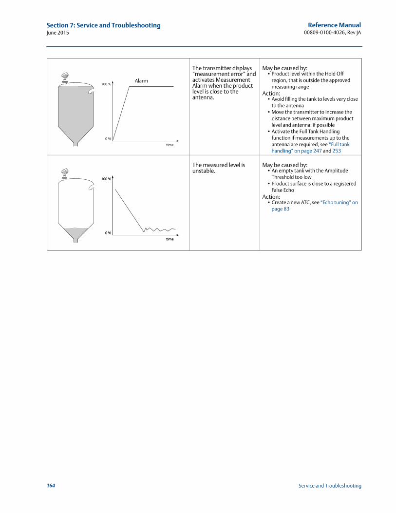
Reference Manual00809-0100-4026, Rev JA
Section 7: Service and TroubleshootingJune 2015
The transmitter displays “measurement error” and activates Measurement Alarm when the product level is close to the antenna.
May be caused by:• Product level within the Hold Off
region, that is outside the approved measuring range
Action:• Avoid filling the tank to levels very close
to the antenna• Move the transmitter to increase the
distance between maximum product level and antenna, if possible
• Activate the Full Tank Handling function if measurements up to the antenna are required, see “Full tank handling” on page 247 and 253
The measured level is unstable.
May be caused by: • An empty tank with the Amplitude
Threshold too low• Product surface is close to a registered
False EchoAction:
• Create a new ATC, see “Echo tuning” on page 83
Alarm
164 Service and Troubleshooting
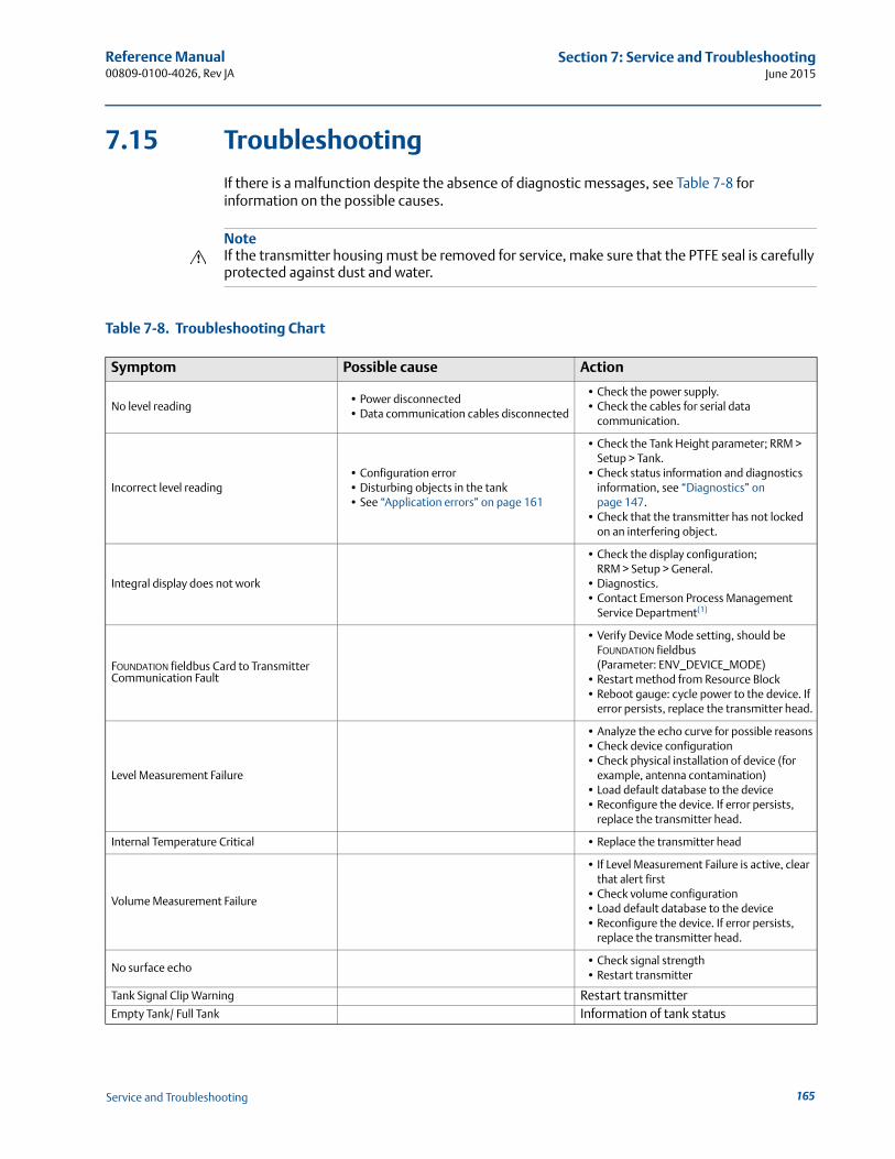
Reference Manual 00809-0100-4026, Rev JA
Section 7: Service and TroubleshootingJune 2015
7.15 Troubleshooting
If there is a malfunction despite the absence of diagnostic messages, see Table 7-8 for information on the possible causes.
NoteIf the transmitter housing must be removed for service, make sure that the PTFE seal is carefully protected against dust and water.
Table 7-8. Troubleshooting Chart
Symptom Possible cause Action
No level reading• Power disconnected• Data communication cables disconnected
• Check the power supply.• Check the cables for serial data
communication.
Incorrect level reading• Configuration error• Disturbing objects in the tank• See “Application errors” on page 161
• Check the Tank Height parameter; RRM > Setup > Tank.
• Check status information and diagnostics information, see “Diagnostics” on page 147.
• Check that the transmitter has not locked on an interfering object.
Integral display does not work
• Check the display configuration; RRM > Setup > General.
• Diagnostics.• Contact Emerson Process Management
Service Department(1)
FOUNDATION fieldbus Card to Transmitter Communication Fault
• Verify Device Mode setting, should be FOUNDATION fieldbus (Parameter: ENV_DEVICE_MODE)
• Restart method from Resource Block• Reboot gauge: cycle power to the device. If
error persists, replace the transmitter head.
Level Measurement Failure
• Analyze the echo curve for possible reasons• Check device configuration• Check physical installation of device (for
example, antenna contamination)• Load default database to the device• Reconfigure the device. If error persists,
replace the transmitter head.
Internal Temperature Critical • Replace the transmitter head
Volume Measurement Failure
• If Level Measurement Failure is active, clear that alert first
• Check volume configuration• Load default database to the device• Reconfigure the device. If error persists,
replace the transmitter head.
No surface echo• Check signal strength• Restart transmitter
Tank Signal Clip Warning Restart transmitterEmpty Tank/ Full Tank Information of tank status
165Service and Troubleshooting
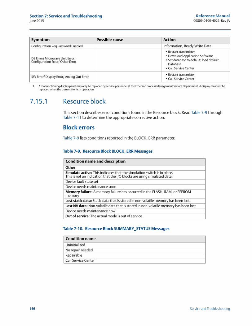
Reference Manual00809-0100-4026, Rev JA
Section 7: Service and TroubleshootingJune 2015
7.15.1 Resource block
This section describes error conditions found in the Resource block. Read Table 7-9 through Table 7-11 to determine the appropriate corrective action.
Block errors
Table 7-9 lists conditions reported in the BLOCK_ERR parameter.
Table 7-9. Resource Block BLOCK_ERR Messages
Table 7-10. Resource Block SUMMARY_STATUS Messages
Configuration Reg Password Enabled Information, Ready Write Data
DB Error/ Microwave Unit Error/ Configuration Error/ Other Error
• Restart transmitter• Download Application Software• Set database to default; load default
Database • Call Service Center
SW Error/ Display Error/ Analog Out Error• Restart transmitter• Call Service Center
1. A malfunctioning display panel may only be replaced by service personnel at the Emerson Process Management Service Department. A display must not be replaced when the transmitter is in operation.
Condition name and description
OtherSimulate active: This indicates that the simulation switch is in place. This is not an indication that the I/O blocks are using simulated data.Device fault state setDevice needs maintenance soonMemory failure: A memory failure has occurred in the FLASH, RAM, or EEPROM memoryLost static data: Static data that is stored in non-volatile memory has been lostLost NV data: Non-volatile data that is stored in non-volatile memory has been lostDevice needs maintenance nowOut of service: The actual mode is out of service
Condition name
UninitializedNo repair neededRepairableCall Service Center
Symptom Possible cause Action
166 Service and Troubleshooting
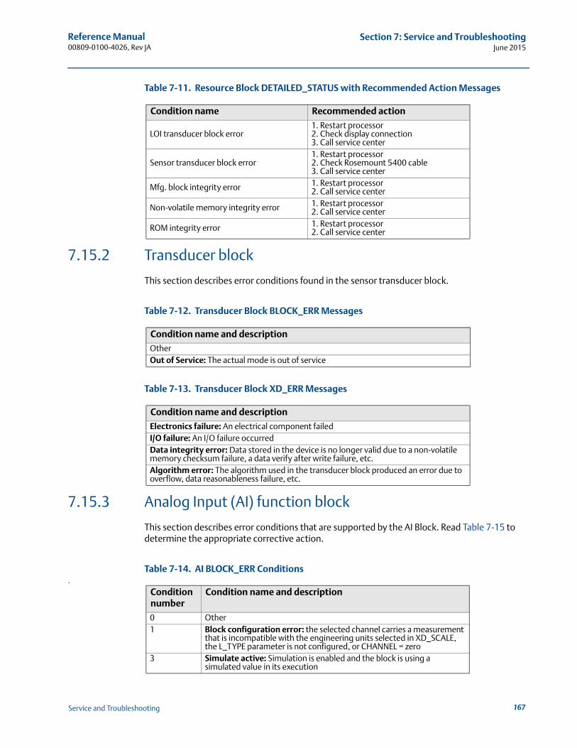
Reference Manual 00809-0100-4026, Rev JA
Section 7: Service and TroubleshootingJune 2015
Table 7-11. Resource Block DETAILED_STATUS with Recommended Action Messages
7.15.2 Transducer block
This section describes error conditions found in the sensor transducer block.
Table 7-12. Transducer Block BLOCK_ERR Messages
Table 7-13. Transducer Block XD_ERR Messages
7.15.3 Analog Input (AI) function block
This section describes error conditions that are supported by the AI Block. Read Table 7-15 to determine the appropriate corrective action.
Table 7-14. AI BLOCK_ERR Conditions.
Condition name Recommended action
LOI transducer block error1. Restart processor2. Check display connection3. Call service center
Sensor transducer block error1. Restart processor2. Check Rosemount 5400 cable3. Call service center
Mfg. block integrity error 1. Restart processor2. Call service center
Non-volatile memory integrity error 1. Restart processor2. Call service center
ROM integrity error 1. Restart processor2. Call service center
Condition name and description
OtherOut of Service: The actual mode is out of service
Condition name and description
Electronics failure: An electrical component failedI/O failure: An I/O failure occurredData integrity error: Data stored in the device is no longer valid due to a non-volatile memory checksum failure, a data verify after write failure, etc.Algorithm error: The algorithm used in the transducer block produced an error due to overflow, data reasonableness failure, etc.
Condition number
Condition name and description
0 Other1 Block configuration error: the selected channel carries a measurement
that is incompatible with the engineering units selected in XD_SCALE, the L_TYPE parameter is not configured, or CHANNEL = zero
3 Simulate active: Simulation is enabled and the block is using a simulated value in its execution
167Service and Troubleshooting
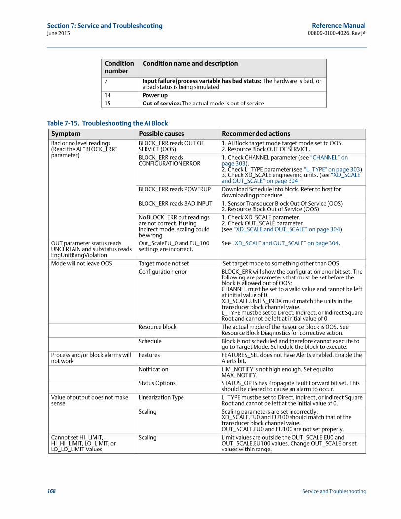
Reference Manual00809-0100-4026, Rev JA
Section 7: Service and TroubleshootingJune 2015
Table 7-15. Troubleshooting the AI Block
7 Input failure/process variable has bad status: The hardware is bad, or a bad status is being simulated
14 Power up15 Out of service: The actual mode is out of service
Symptom Possible causes Recommended actions
Bad or no level readings(Read the AI “BLOCK_ERR” parameter)
BLOCK_ERR reads OUT OF SERVICE (OOS)
1. AI Block target mode target mode set to OOS.2. Resource Block OUT OF SERVICE.
BLOCK_ERR reads CONFIGURATION ERROR
1. Check CHANNEL parameter (see “CHANNEL” on page 303).2. Check L_TYPE parameter (see “L_TYPE” on page 303)3. Check XD_SCALE engineering units. (see “XD_SCALE and OUT_SCALE” on page 304
BLOCK_ERR reads POWERUP Download Schedule into block. Refer to host for downloading procedure.
BLOCK_ERR reads BAD INPUT 1. Sensor Transducer Block Out Of Service (OOS)2. Resource Block Out of Service (OOS)
No BLOCK_ERR but readings are not correct. If using Indirect mode, scaling could be wrong
1. Check XD_SCALE parameter.2. Check OUT_SCALE parameter. (see “XD_SCALE and OUT_SCALE” on page 304)
OUT parameter status reads UNCERTAIN and substatus reads EngUnitRangViolation
Out_ScaleEU_0 and EU_100 settings are incorrect.
See “XD_SCALE and OUT_SCALE” on page 304.
Mode will not leave OOS Target mode not set Set target mode to something other than OOS.Configuration error BLOCK_ERR will show the configuration error bit set. The
following are parameters that must be set before the block is allowed out of OOS:CHANNEL must be set to a valid value and cannot be left at initial value of 0.XD_SCALE.UNITS_INDX must match the units in the transducer block channel value.L_TYPE must be set to Direct, Indirect, or Indirect Square Root and cannot be left at initial value of 0.
Resource block The actual mode of the Resource block is OOS. See Resource Block Diagnostics for corrective action.
Schedule Block is not scheduled and therefore cannot execute to go to Target Mode. Schedule the block to execute.
Process and/or block alarms will not work
Features FEATURES_SEL does not have Alerts enabled. Enable the Alerts bit.
Notification LIM_NOTIFY is not high enough. Set equal to MAX_NOTIFY.
Status Options STATUS_OPTS has Propagate Fault Forward bit set. This should be cleared to cause an alarm to occur.
Value of output does not make sense
Linearization Type L_TYPE must be set to Direct, Indirect, or Indirect Square Root and cannot be left at the initial value of 0.
Scaling Scaling parameters are set incorrectly:XD_SCALE.EU0 and EU100 should match that of the transducer block channel value.OUT_SCALE.EU0 and EU100 are not set properly.
Cannot set HI_LIMIT, HI_HI_LIMIT, LO_LIMIT, or LO_LO_LIMIT Values
Scaling Limit values are outside the OUT_SCALE.EU0 and OUT_SCALE.EU100 values. Change OUT_SCALE or set values within range.
Condition number
Condition name and description
168 Service and Troubleshooting

Reference Manual 00809-0100-4026, Rev JA
Section 8: Safety Instrumented Systems (4-20 mA Only)June 2015
Section 8 Safety Instrumented Systems (4-20 mA Only)
Safety messages . . . . . . . . . . . . . . . . . . . . . . . . . . . . . . . . . . . . . . . . . . . . . . . . . . . . . . . . . . . . page 169Overview . . . . . . . . . . . . . . . . . . . . . . . . . . . . . . . . . . . . . . . . . . . . . . . . . . . . . . . . . . . . . . . . . . page 170Functional specifications . . . . . . . . . . . . . . . . . . . . . . . . . . . . . . . . . . . . . . . . . . . . . . . . . . . . . page 171Installation . . . . . . . . . . . . . . . . . . . . . . . . . . . . . . . . . . . . . . . . . . . . . . . . . . . . . . . . . . . . . . . . . page 171Configuration . . . . . . . . . . . . . . . . . . . . . . . . . . . . . . . . . . . . . . . . . . . . . . . . . . . . . . . . . . . . . . page 173Operation and maintenance . . . . . . . . . . . . . . . . . . . . . . . . . . . . . . . . . . . . . . . . . . . . . . . . . . page 174References . . . . . . . . . . . . . . . . . . . . . . . . . . . . . . . . . . . . . . . . . . . . . . . . . . . . . . . . . . . . . . . . . page 176Spare parts . . . . . . . . . . . . . . . . . . . . . . . . . . . . . . . . . . . . . . . . . . . . . . . . . . . . . . . . . . . . . . . . . page 176Terms and definitions . . . . . . . . . . . . . . . . . . . . . . . . . . . . . . . . . . . . . . . . . . . . . . . . . . . . . . . page 176
8.1 Safety messages
Procedures and instructions in this section may require special precautions to ensure the safety of the personnel performing the operations. Information that raises potential safety issues is indicated by a warning symbol ( ). Refer to the following safety messages before performing an operation preceded by this symbol.
Failure to follow these installation guidelines could result in death or serious injury.
Make sure only qualified personnel perform the installation. Use the equipment only as specified in this manual. Failure to do so may impair the
protection provided by the equipment.Explosions could result in death or serious injury.
Verify that the operating environment of the transmitter is consistent with the appropriate hazardous locations specifications.
Before connecting a Field Communicator in an explosive atmosphere, make sure the instruments in the loop are installed in accordance with intrinsically safe or non-incendive field wiring practices.
Electrical shock can result in death or serious injury.
Use extreme caution when making contact with the leads and terminals.Antennas with non-conducting surfaces.
Antennas with non-conducting surfaces (e.g. rod antenna and process seal antenna) may generate an ignition-capable level of electrostatic charge under extreme conditions. Therefore, when the antenna is used in a potentially explosive atmosphere, appropriate measures must be taken to prevent electrostatic discharge.
169Safety Instrumented Systems (4-20 mA Only)
Reference Manual00809-0100-4026, Rev JA
Section 8: Safety Instrumented Systems (4-20 mA Only)June 2015
8.2 Overview
The following section applies to the 4-20 mA Rosemount 5400 Series with QS Prior-Use Certificate of FMEDA data transmitter used in Safety Instrumented Systems (SIS) applications. The 5400 QS Prior Use option with analog output provides overfill and empty tank protection to improve the system safety. The transmitter is classified as a Type B device. It contains self-diag-nostics and is programmed to send its output to either a high or low failure state upon internal detection of a failure.
An independent third party approval of the FMEDA (detailed performance assessment) was conducted by SP (Technical Research Institute of Sweden) according to IEC 61508:2010. The FMEDA is performed to determine failure rates, calculate the Safe Failure Fraction (SFF), and the average Probability of Failure on Demand (PFDAVG). The hardware assessment is one of the steps taken to achieve functional safety per IEC 61508 / IEC 61511. It provides the failure rate data suitable for prior-use assessment.
NoteRefer to the Rosemount 5400 Series FMEDA(1) report for failure rate data, additional details, and assumptions regarding the failure rate analysis.
8.2.1 Applicable models
Table 8-1 lists the versions of the Rosemount 5400 Series transmitter that have been considered for the hardware assessment, to which this section applies.
Table 8-1. Rosemount 5400 Series QS Option Model Codes
To identify a 5400 QS Prior Use transmitter, verify the option code QS in the model code, on the label affixed to the outside of the transmitter head.
Any substitution of non-authorized parts or repair, other than exchanging the complete transmitter head or antenna assembly, may jeopardize safety and is prohibited.
Unauthorized changes to the product are strictly prohibited as they may unintentionally and unpredictably alter performance and jeopardize safety. Unauthorized changes that interfere with the integrity of the welds or flanges, such as making additional perforations, compromise product integrity and safety. Equipment ratings and certifications are no longer valid on any products that have been damaged or modified without the prior written permission of Emerson Process Management. Any continued use of product that has been damaged or modified without the written authorization is at the customer’s sole risk and expense.
1. The Rosemount 5400 Series FMEDA report is accessible at www.emersonprocess.com/rosemount/safety/PriorUse.htm.
QS option model codes1 Model 5401xHxxxxxxxxxxxxQS(1)
1. Not available with option code C4 or C8.
2 Model 5402xHxxxxxxxxxxxxQS(1)
170 Safety Instrumented Systems (4-20 mA Only)
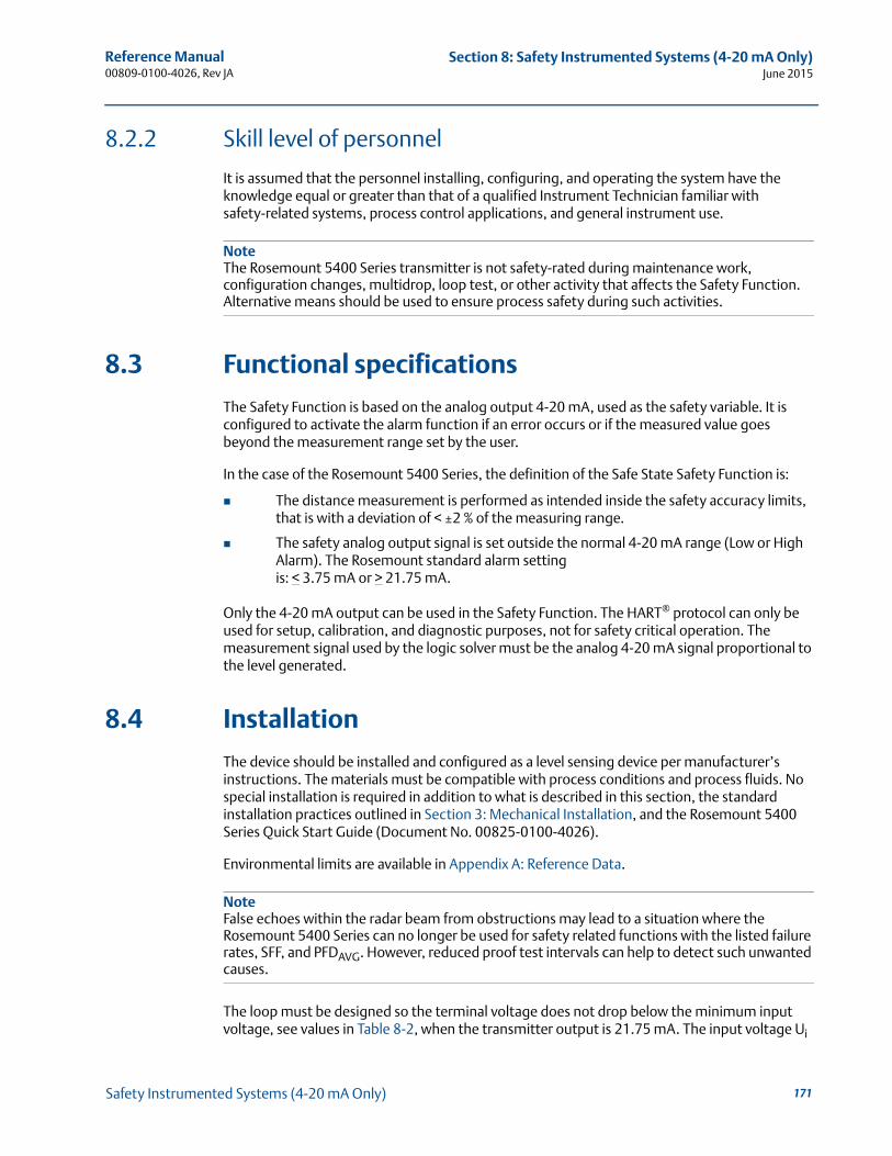
Reference Manual 00809-0100-4026, Rev JA
Section 8: Safety Instrumented Systems (4-20 mA Only)June 2015
8.2.2 Skill level of personnel
It is assumed that the personnel installing, configuring, and operating the system have the knowledge equal or greater than that of a qualified Instrument Technician familiar with safety-related systems, process control applications, and general instrument use.
NoteThe Rosemount 5400 Series transmitter is not safety-rated during maintenance work, configuration changes, multidrop, loop test, or other activity that affects the Safety Function. Alternative means should be used to ensure process safety during such activities.
8.3 Functional specifications
The Safety Function is based on the analog output 4-20 mA, used as the safety variable. It is configured to activate the alarm function if an error occurs or if the measured value goes beyond the measurement range set by the user.
In the case of the Rosemount 5400 Series, the definition of the Safe State Safety Function is:
The distance measurement is performed as intended inside the safety accuracy limits, that is with a deviation of < ±2 % of the measuring range.
The safety analog output signal is set outside the normal 4-20 mA range (Low or High Alarm). The Rosemount standard alarm setting is: < 3.75 mA or > 21.75 mA.
Only the 4-20 mA output can be used in the Safety Function. The HART® protocol can only be used for setup, calibration, and diagnostic purposes, not for safety critical operation. The measurement signal used by the logic solver must be the analog 4-20 mA signal proportional to the level generated.
8.4 Installation
The device should be installed and configured as a level sensing device per manufacturer’s instructions. The materials must be compatible with process conditions and process fluids. No special installation is required in addition to what is described in this section, the standard installation practices outlined in Section 3: Mechanical Installation, and the Rosemount 5400 Series Quick Start Guide (Document No. 00825-0100-4026).
Environmental limits are available in Appendix A: Reference Data.
NoteFalse echoes within the radar beam from obstructions may lead to a situation where the Rosemount 5400 Series can no longer be used for safety related functions with the listed failure rates, SFF, and PFDAVG. However, reduced proof test intervals can help to detect such unwanted causes.
The loop must be designed so the terminal voltage does not drop below the minimum input voltage, see values in Table 8-2, when the transmitter output is 21.75 mA. The input voltage Ui
171Safety Instrumented Systems (4-20 mA Only)
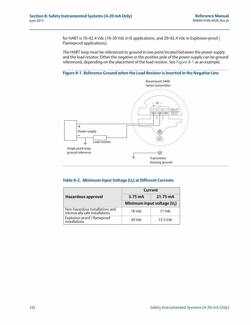
Reference Manual00809-0100-4026, Rev JA
Section 8: Safety Instrumented Systems (4-20 mA Only)June 2015
for HART is 16-42.4 Vdc (16-30 Vdc in IS applications, and 20-42.4 Vdc in Explosion-proof / Flameproof applications).
The HART loop must be referenced to ground in one point located between the power supply and the load resistor. Either the negative or the positive pole of the power supply can be ground referenced, depending on the placement of the load resistor. See Figure 8-1 as an example.
Figure 8-1. Reference Ground when the Load Resistor is Inserted in the Negative Line
Table 8-2. Minimum Input Voltage (Ui) at Different Currents
Hazardous approval
Current
3.75 mA 21.75 mA
Minimum input voltage (Ui)Non-hazardous Installations and intrinsically safe installations 16 Vdc 11 Vdc
Explosion-proof / flameproof installations 20 Vdc 15.5 Vdc
Power supply
Load resistor
Single point loop ground reference
Rosemount 5400 Series transmitter
Transmitter housing ground
172 Safety Instrumented Systems (4-20 mA Only)
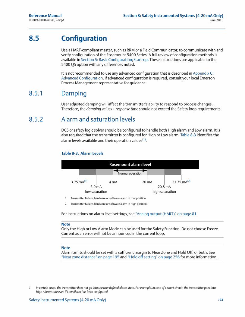
Reference Manual 00809-0100-4026, Rev JA
Section 8: Safety Instrumented Systems (4-20 mA Only)June 2015
8.5 Configuration
Use a HART-compliant master, such as RRM or a Field Communicator, to communicate with and verify configuration of the Rosemount 5400 Series. A full review of configuration methods is available in Section 5: Basic Configuration/Start-up. These instructions are applicable to the 5400 QS option with any differences noted.
It is not recommended to use any advanced configuration that is described in Appendix C: Advanced Configuration. If advanced configuration is required, consult your local Emerson Process Management representative for guidance.
8.5.1 Damping
User adjusted damping will affect the transmitter’s ability to respond to process changes. Therefore, the damping values + response time should not exceed the Safety loop requirements.
8.5.2 Alarm and saturation levels
DCS or safety logic solver should be configured to handle both High alarm and Low alarm. It is also required that the transmitter is configured for High or Low alarm. Table 8-3 identifies the alarm levels available and their operation values(1).
Table 8-3. Alarm Levels
For instructions on alarm level settings, see “Analog output (HART)” on page 81.
NoteOnly the High or Low Alarm Mode can be used for the Safety Function. Do not choose Freeze Current as an error will not be announced in the current loop.
NoteAlarm Limits should be set with a sufficient margin to Near Zone and Hold Off, or both. See “Near zone distance” on page 195 and “Hold off setting” on page 256 for more information.
1. In certain cases, the transmitter does not go into the user defined alarm state. For example, in case of a short circuit, the transmitter goes into High Alarm state even if Low Alarm has been configured.
Rosemount alarm level
Normal operation
3.75 mA(1)
1. Transmitter Failure, hardware or software alarm in Low position.
4 mA 20 mA 21.75 mA(2)
2. Transmitter Failure, hardware or software alarm in High position.
3.9 mA 20.8 mAlow saturation high saturation
173Safety Instrumented Systems (4-20 mA Only)
Reference Manual00809-0100-4026, Rev JA
Section 8: Safety Instrumented Systems (4-20 mA Only)June 2015
8.5.3 Amplitude threshold
For amplitude thresholds, verify that:
the Amplitude Threshold is at least 50 % greater than the amplitude of disturbances. For example, if the amplitude of disturbance is 1000 mV, the Amplitude Threshold should be at least 1500 mV.
the Amplitude Threshold has an amplitude of at least 100 mV
the Amplitude Threshold is set to 20-50 % of the signal amplitude of the product surface
Amplitude Thresholds should be verified with the measured product in the tank. It is not recommended to register any false echo areas. For more information on Amplitude Thresholds, see “Echo tuning” on page 83, “ATC” on page 84, and “Analyzing the measurement signal” on page 134.
8.5.4 Write protection
A Rosemount 5400 Series transmitter can be protected from unintentional configuration changes by a password protected function. It is recommended to use write protection described in “Write protecting a transmitter” on page 154.
8.5.5 Site acceptance
After the installation and configuration, proper operation of the transmitter should be verified. A site acceptance test is therefore recommended. The proof test outlined in this section can be used for this. Note that re-verification of the transmitter operation is recommended if the configuration is changed.
8.6 Operation and maintenance
8.6.1 General
The Rosemount 5400 Series QS option must be tested at regular intervals to confirm that the overfill and empty tank protection function result in the desired system response. The required proof test intervals are dependent on the configuration of the transmitter and the process environment. It is the responsibility of the operator/owner of the system to determine the sufficient time interval and verify it is followed. See the FMEDA(1) report for additional details or references.
If the overfill and empty tank protection function cannot be tested by a controlled filling to the response height, suitable simulation of the level must be used to make the level sensor respond.
The following proof test is recommended. If an error is found in the safety functionality, the measuring system must be switched out of service and the process held in a safe state by means of other measures. Proof test results and corrective actions taken must be documented at www.emersonprocess.com/rosemount/safety.
1. The Rosemount 5400 Series FMEDA report is accessible at www.emersonprocess.com/rosemount/safety/PriorUse.htm.
174 Safety Instrumented Systems (4-20 mA Only)
Reference Manual 00809-0100-4026, Rev JA
Section 8: Safety Instrumented Systems (4-20 mA Only)June 2015
Proof test
This test detects approximately 95 % of the possible Dangerous Undetected (DU) failures of the transmitter. Instructions for performing the proof test with the Field Communicator, Rosemount Radar Master, or AMS, are available in Appendix D: Performing Proof Test.Note that prior to conducting the test, the echo curve should be inspected to ensure that no disturbing echoes affecting the measurement performance are present in the tank.
Required Tools: HART host/communicator and mA meter.
1. Bypass the logic solver or take other appropriate actions to avoid false trip.
2. Disable write protection if the function is enabled.
3. Using Loop Test, enter the mA value representing a high alarm current output and verify that the analog current reaches that value using the mA meter.This step tests for compliance voltage problems, such as low loop power supply voltage or increased wiring resistance.
4. Using Loop Test, enter the mA value representing a low alarm current output and verify that the analog current reaches that value using the reference meter.This step tests for possible quiescent current related failures.
5. Perform a two-point calibration check of the transmitter by adjusting the product level in two points in the measuring range(1). Verify that the current output corresponds to the level input values using a known reference measurement.This step verifies that the analog output is correct in the operating range and that the Primary Variable is properly configured.
6. Enable write protection.
7. Restore the loop to full operation.
8. Remove the bypass from the safety logic solver or otherwise restore normal operation.
9. Document the test result for future reference.
For troubleshooting the transmitter, see Section 7: Service and Troubleshooting.
8.6.2 Inspection
Visual inspection
It is recommended to inspect the antenna for possible build up or clogging.
Special tools
Not required.
1. For best performance, use the 4-20 mA range points as calibration points.
175Safety Instrumented Systems (4-20 mA Only)
Reference Manual00809-0100-4026, Rev JA
Section 8: Safety Instrumented Systems (4-20 mA Only)June 2015
Product repair
The Rosemount 5400 Series is repairable by major component replacement. All failures detected by the transmitter diagnostics or by the proof test must be reported. Feedback can be submitted electronically at www.emersonprocess.com/rosemount/safety (Contact Us).
8.7 References
8.7.1 Specifications
The Rosemount 5400 Series must be operated in accordance with the functional and performance specifications provided in Appendix A: Reference Data.
8.7.2 Failure rate data
The FMEDA report includes failure rates and common cause Beta factor estimates. The full report is accessible at www.emersonprocess.com/rosemount/safety/PriorUse.htm.
8.7.3 Useful lifetime
The established failure rates of electrical components apply within the useful lifetime, which should be based on experience. According to IEC 61508-2, 7.4.7.4, note 3, the useful lifetime often lies within a range of 8 to 12 years for transmitters.
8.8 Spare parts
Additional spare parts are available in Appendix A: Reference Data.
8.9 Terms and definitions
FMEDA
Failure Modes, Effects and Diagnostic Analysis
HART
Highway Addressable Remote Transducer
PFDAVG
Average Probability of Failure on Demand
SFF
Safe Failure Fraction
176 Safety Instrumented Systems (4-20 mA Only)
Reference Manual 00809-0100-4026, Rev JA
Section 8: Safety Instrumented Systems (4-20 mA Only)June 2015
SIF
Safety Instrumented Function
SIL
Safety Integrity Level, discrete level (one out of a possible four) for specifying the safety integrity requirements of the safety functions to be allocated to the E/E/PE safety-related systems, where Safety Integrity Level 4 has the highest level of safety integrity, and Safety Integrity Level 1 has the lowest.
SIS
Safety Instrumented System – Implementation of one or more Safety Instrumented Functions. A SIS is composed of any combination of sensor(s), logic solver(s), and final element(s).
Type B device
Complex device (using microcontrollers or programmable logic)
177Safety Instrumented Systems (4-20 mA Only)

178
Reference Manual00809-0100-4026, Rev JA
Section 8: Safety Instrumented Systems (4-20 mA Only)June 2015
Safety Instrumented Systems (4-20 mA Only)
Reference Manual 00809-0100-4026, Rev JA
Appendix A: Reference dataJune 2015
Appendix A Reference Data
Functional specifications . . . . . . . . . . . . . . . . . . . . . . . . . . . . . . . . . . . . . . . . . . . . . . . . . . . . . page 179Performance specifications . . . . . . . . . . . . . . . . . . . . . . . . . . . . . . . . . . . . . . . . . . . . . . . . . . page 191Physical specifications . . . . . . . . . . . . . . . . . . . . . . . . . . . . . . . . . . . . . . . . . . . . . . . . . . . . . . . page 198Dimensional drawings and mechanical properties . . . . . . . . . . . . . . . . . . . . . . . . . . . . . . . page 202Ordering information . . . . . . . . . . . . . . . . . . . . . . . . . . . . . . . . . . . . . . . . . . . . . . . . . . . . . . . . page 208
A.1 Functional specifications
A.1.1 General
Field of liquid application
Ideal for liquids and slurries in tanks, vessels, containers, reactor vessels, and underground tanks. Applications with sticky, viscous, corrosive, condensing, and crystallizing product.
Model 5402, best choice for a broad range of applications and suitable for mounting in valves and bridles/stilling wells
Model 5401, suitable for some extreme process conditions such as condensing vapors, product build-up, and heavy turbulence
Field of solids application Model 5402 with 4 inch cone antenna for a broad range of solids applications.
Measurement principle
Pulsed, free propagating radar. Low frequency (model 5401, 6 GHz) and high frequency (model 5402, 26 GHz). (see “Theory of operation” on page 7 for details)
Microwave output power
< 1 mW
Internal power consumption
< 50 mW in normal operation
Humidity
0 - 100% relative humidity, non-condensing
Start-up time
< 40 s
179Reference Data
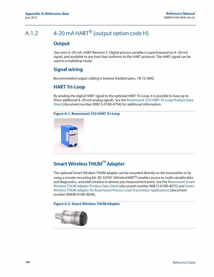
Reference Manual00809-0100-4026, Rev JA
Appendix A: Reference dataJune 2015
A.1.2 4-20 mA HART® (output option code H)
Output
Two-wire 4–20 mA, HART Revision 5. Digital process variable is superimposed on 4–20 mA signal, and available to any host that conforms to the HART protocol. The HART signal can be used in a multidrop mode.
Signal wiring
Recommended output cabling is twisted shielded pairs, 18-12 AWG
HART Tri-Loop
By sending the digital HART signal to the optional HART Tri-Loop, it is possible to have up to three additional 4–20 mA analog signals. See the Rosemount 333 HART Tri-Loop Product Data Sheet (document number 00813-0100-4754) for additional information.
Figure A-1. Rosemount 333 HART Tri-Loop
Smart Wireless THUM™ Adapter
The optional Smart Wireless THUM adapter can be mounted directly on the transmitter or by using a remote mounting kit. IEC 62591 (WirelessHART®) enables access to multi-variable data and diagnostics, and adds wireless to almost any measurement point. See the Rosemount Smart Wireless THUM Adapter Product Data Sheet (document number 00813-0100-4075) and Smart Wireless THUM Adapter for Rosemount Process Level Transmitter Applications (document number 00840-0100-4026).
Figure A-2. Smart Wireless THUM Adapter
180 Reference Data
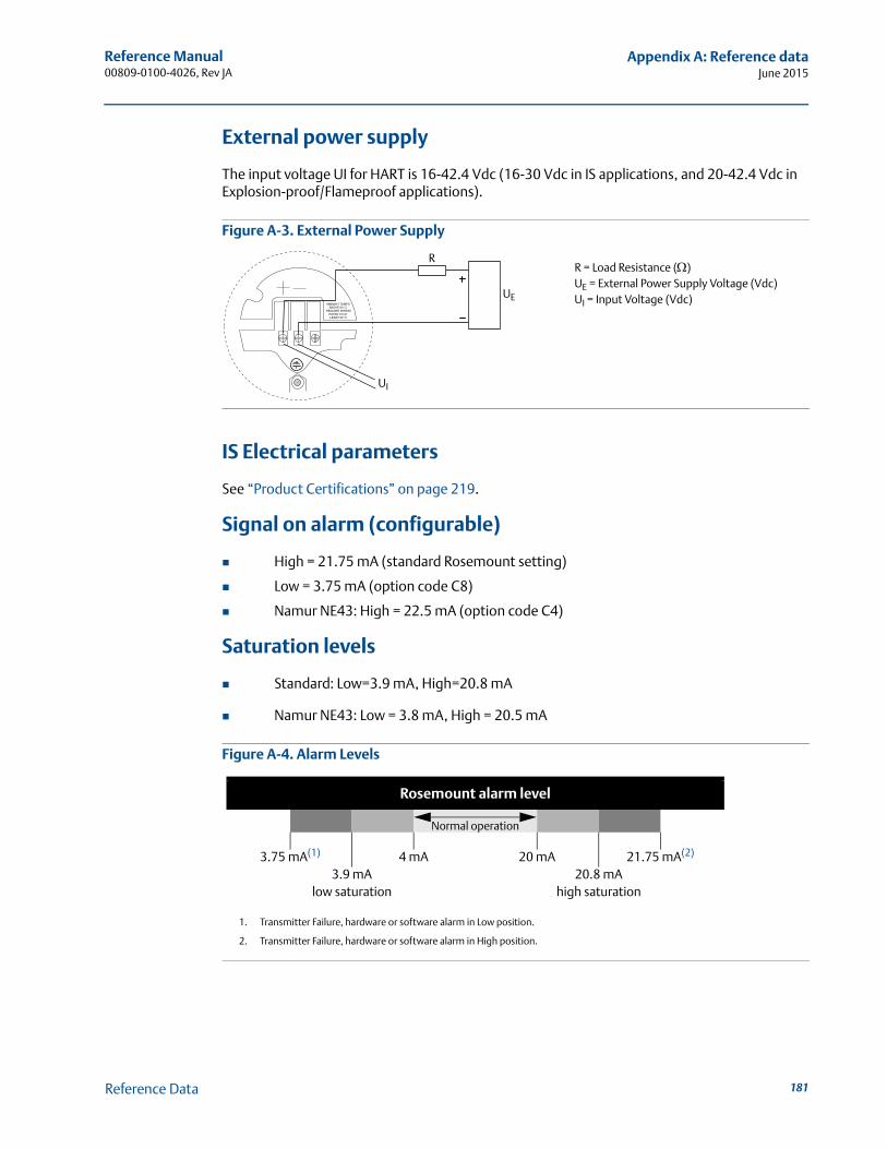
Reference Manual 00809-0100-4026, Rev JA
Appendix A: Reference dataJune 2015
External power supply
The input voltage UI for HART is 16-42.4 Vdc (16-30 Vdc in IS applications, and 20-42.4 Vdc in Explosion-proof/Flameproof applications).
Figure A-3. External Power Supply
IS Electrical parameters
See “Product Certifications” on page 219.
Signal on alarm (configurable)
High = 21.75 mA (standard Rosemount setting)
Low = 3.75 mA (option code C8)
Namur NE43: High = 22.5 mA (option code C4)
Saturation levels
Standard: Low=3.9 mA, High=20.8 mA
Namur NE43: Low = 3.8 mA, High = 20.5 mA
Figure A-4. Alarm Levels
R = Load Resistance ()UE = External Power Supply Voltage (Vdc)UI = Input Voltage (Vdc)
UI
R
UE
Rosemount alarm level
Normal operation
3.75 mA(1)
1. Transmitter Failure, hardware or software alarm in Low position.
4 mA 20 mA 21.75 mA(2)
2. Transmitter Failure, hardware or software alarm in High position.
3.9 mA 20.8 mAlow saturation high saturation
181Reference Data
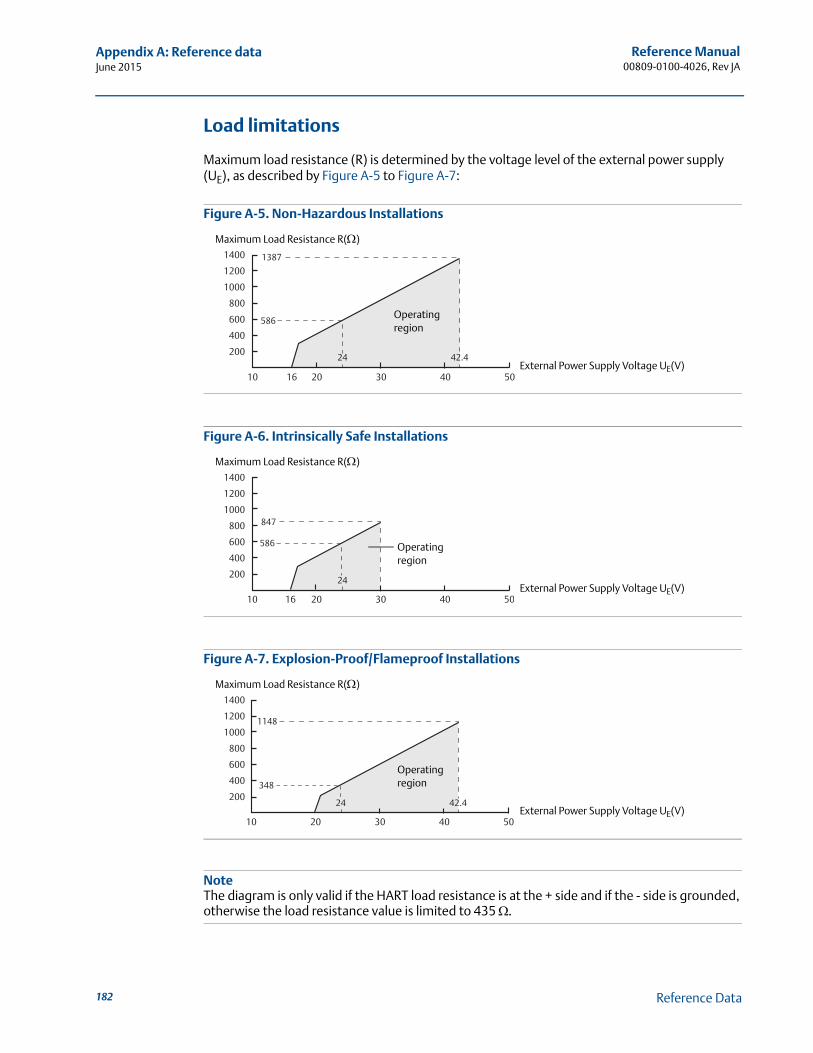
Reference Manual00809-0100-4026, Rev JA
Appendix A: Reference dataJune 2015
Load limitations
Maximum load resistance (R) is determined by the voltage level of the external power supply (UE), as described by Figure A-5 to Figure A-7:
Figure A-5. Non-Hazardous Installations
Figure A-6. Intrinsically Safe Installations
Figure A-7. Explosion-Proof/Flameproof Installations
NoteThe diagram is only valid if the HART load resistance is at the + side and if the - side is grounded, otherwise the load resistance value is limited to 435 .
10 2016 30
200
400
600
800
1000
1200
1400
40 50
42.424
586
1387
External Power Supply Voltage UE(V)
Maximum Load Resistance R()
Operating region
10 2016 30
200
400
600
800
1000
1200
1400
40 50
24
586
847
External Power Supply Voltage UE(V)
Maximum Load Resistance R()
Operating region
10 20 30
200
400
600
800
1000
1200
1400
40 50
24 42.4
1148
348
External Power Supply Voltage UE(V)
Maximum Load Resistance R()
Operating region
182 Reference Data
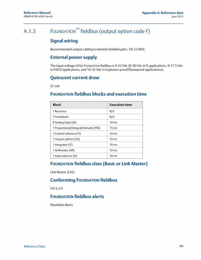
Reference Manual 00809-0100-4026, Rev JA
Appendix A: Reference dataJune 2015
A.1.3 FOUNDATION™ fieldbus (output option code F)
Signal wiring
Recommended output cabling is twisted shielded pairs, 18-12 AWG
External power supply
The input voltage UI for FOUNDATION fieldbus is 9-32 Vdc (9-30 Vdc in IS applications, 9-17.5 Vdc in FISCO applications, and 16-32 Vdc in Explosion-proof/flameproof applications).
Quiescent current draw
21 mA
FOUNDATION fieldbus blocks and execution time
FOUNDATION fieldbus class (Basic or Link Master)
Link Master (LAS)
Conforming FOUNDATION fieldbus
ITK 5.2.0
FOUNDATION fieldbus alerts
PlantWeb Alerts
Block Execution time
1 Resource N/A
3 Transducer N/A
6 Analog input (AI) 10 ms
1 Proportional/Integral/Derivate (PID) 15 ms
1 Control selector (CS) 10 ms
1 Output splitter (OS) 10 ms
1 Integrator (IT) 10 ms
1 Arithmetic (AR) 10 ms
1 Input selector (IS) 10 ms
183Reference Data
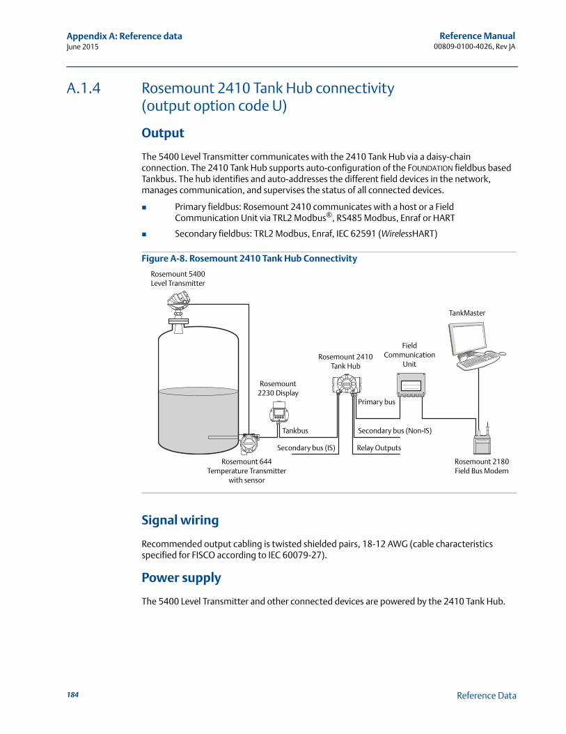
Reference Manual00809-0100-4026, Rev JA
Appendix A: Reference dataJune 2015
A.1.4 Rosemount 2410 Tank Hub connectivity (output option code U)
Output
The 5400 Level Transmitter communicates with the 2410 Tank Hub via a daisy-chain connection. The 2410 Tank Hub supports auto-configuration of the FOUNDATION fieldbus based Tankbus. The hub identifies and auto-addresses the different field devices in the network, manages communication, and supervises the status of all connected devices.
Primary fieldbus: Rosemount 2410 communicates with a host or a Field Communication Unit via TRL2 Modbus®, RS485 Modbus, Enraf or HART
Secondary fieldbus: TRL2 Modbus, Enraf, IEC 62591 (WirelessHART)
Figure A-8. Rosemount 2410 Tank Hub Connectivity
Signal wiring
Recommended output cabling is twisted shielded pairs, 18-12 AWG (cable characteristics specified for FISCO according to IEC 60079-27).
Power supply
The 5400 Level Transmitter and other connected devices are powered by the 2410 Tank Hub.
TankMaster
Rosemount 2410 Tank Hub
Field Communication
Unit
Rosemount 5400 Level Transmitter
Rosemount 644 Temperature Transmitter
with sensor
Tankbus Secondary bus (Non-IS)
Relay OutputsSecondary bus (IS)
Rosemount 2180 Field Bus Modem
Primary bus
Rosemount 2230 Display
184 Reference Data
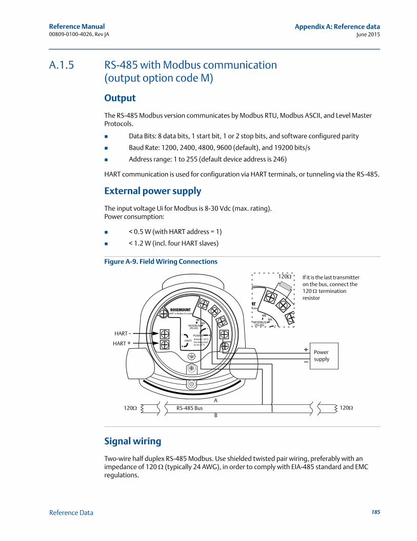
Reference Manual 00809-0100-4026, Rev JA
Appendix A: Reference dataJune 2015
A.1.5 RS-485 with Modbus communication (output option code M)
Output
The RS-485 Modbus version communicates by Modbus RTU, Modbus ASCII, and Level Master Protocols.
Data Bits: 8 data bits, 1 start bit, 1 or 2 stop bits, and software configured parity
Baud Rate: 1200, 2400, 4800, 9600 (default), and 19200 bits/s
Address range: 1 to 255 (default device address is 246)
HART communication is used for configuration via HART terminals, or tunneling via the RS-485.
External power supply
The input voltage Ui for Modbus is 8-30 Vdc (max. rating).Power consumption:
< 0.5 W (with HART address = 1)
< 1.2 W (incl. four HART slaves)
Figure A-9. Field Wiring Connections
Signal wiring
Two-wire half duplex RS-485 Modbus. Use shielded twisted pair wiring, preferably with an impedance of 120 (typically 24 AWG), in order to comply with EIA-485 standard and EMC regulations.
MODBUS
POWER
HART
(RS-485)
HART to Modbus Converter
MBMA
-
- +
+
Ambients > 60 ºCUse wiring ratedfor min 90 ºC
RS-485 BusB
A
Power supply
HART +HART -
120120
If it is the last transmitter on the bus, connect the 120 termination resistor
MODBUS(RS-485)
verter
MBMA
-
120
185Reference Data

Reference Manual00809-0100-4026, Rev JA
Appendix A: Reference dataJune 2015
Ground (common mode) voltage limit
± 7 V
Bus termination
Standard RS-485 bus termination per EIA-485
186 Reference Data
Reference Manual 00809-0100-4026, Rev JA
Appendix A: Reference dataJune 2015
A.1.6 Display and configuration
Integral display (option code M1)
5-digit integral display. The process variables listed in “Output variables” on page 188 can be presented. If more than one variable is chosen, carousel toggling of data is used. The display also shows diagnostics and error information.
Remote display
Data can be read remotely by using the Rosemount 751 Field Signal Indicator (see Product Data Sheet, document number 00813-0100-4378) for 4-20 mA / HART, or Rosemount 752 Remote Indicator for FOUNDATION fieldbus (see Product Data Sheet, document number 00813-0100-4377).
Configuration tools
Emerson Field Communicator (e.g. 375/475 Field Communicator), Rosemount Radar Master (RRM) software package (included with delivery of transmitter), Emerson AMS® Device Manager or any other EDDL or enhanced-EDDL host, or DeltaV™ or any other DD (Device Description) compatible host systems. Certificates are available from all major host system vendors.
NoteDTM (compliant with version 1.2 of the FDT®/DTM™ specification) supporting configuration in for instance Yokogawa Fieldmate/PRM, E+H FieldCare™, and PACTware™.
NoteTo communicate using RRM or AMS Device Manager, a HART modem is required. The HART modem is available as an RS232 or USB version (see Table A-9 on page 217).
NoteThe transmitter can be pre-configured by selecting option code C1 (see page 211), and sending a complete Configuration Data Sheet (CDS). The CDS is available from www.rosemount.com.
Output units
Level and distance: ft, in., m, cm, or mm
Volume: ft3, in.3, US gals, Imp gals, barrels, yd3, m3, or liters
Level rate: ft/s, m/s
Temperature: °F, °C
187Reference Data
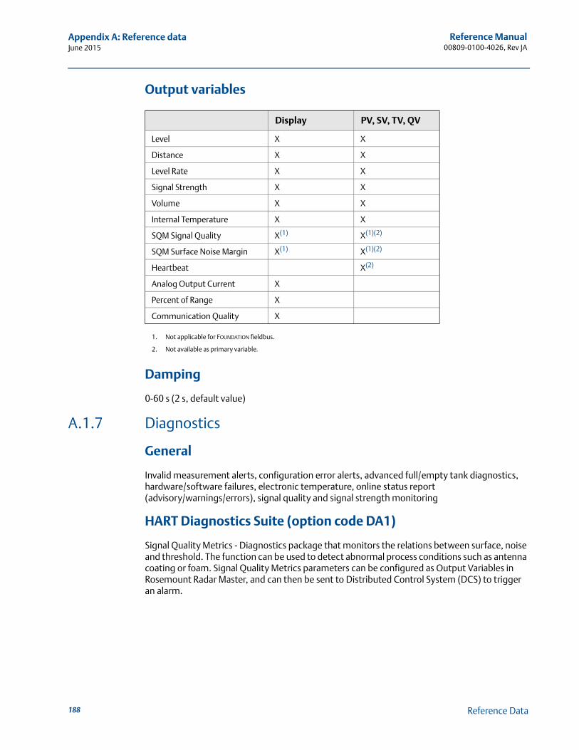
Reference Manual00809-0100-4026, Rev JA
Appendix A: Reference dataJune 2015
Output variables
Damping
0-60 s (2 s, default value)
A.1.7 Diagnostics
General
Invalid measurement alerts, configuration error alerts, advanced full/empty tank diagnostics, hardware/software failures, electronic temperature, online status report (advisory/warnings/errors), signal quality and signal strength monitoring
HART Diagnostics Suite (option code DA1)
Signal Quality Metrics - Diagnostics package that monitors the relations between surface, noise and threshold. The function can be used to detect abnormal process conditions such as antenna coating or foam. Signal Quality Metrics parameters can be configured as Output Variables in Rosemount Radar Master, and can then be sent to Distributed Control System (DCS) to trigger an alarm.
Display PV, SV, TV, QV
Level X X
Distance X X
Level Rate X X
Signal Strength X X
Volume X X
Internal Temperature X X
SQM Signal Quality X(1)
1. Not applicable for FOUNDATION fieldbus.
X(1)(2)
2. Not available as primary variable.
SQM Surface Noise Margin X(1) X(1)(2)
Heartbeat X(2)
Analog Output Current X
Percent of Range X
Communication Quality X
188 Reference Data
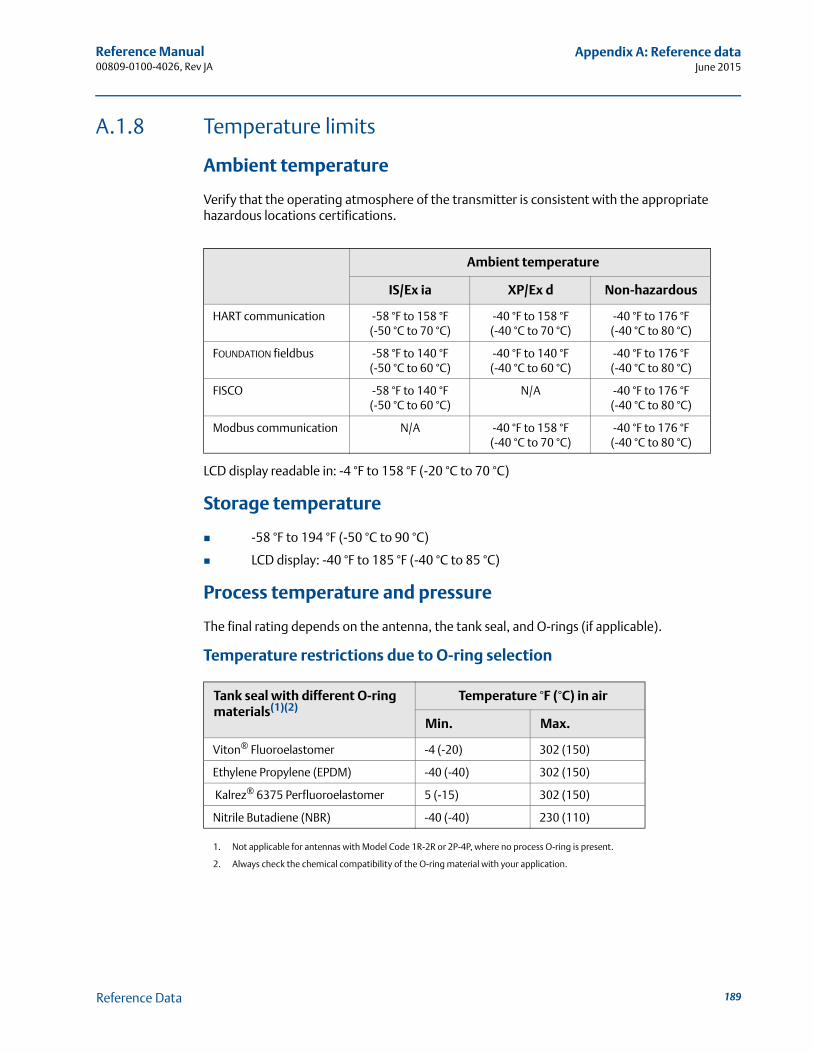
Reference Manual 00809-0100-4026, Rev JA
Appendix A: Reference dataJune 2015
A.1.8 Temperature limits
Ambient temperature
Verify that the operating atmosphere of the transmitter is consistent with the appropriate hazardous locations certifications.
LCD display readable in: -4 °F to 158 °F (-20 °C to 70 °C)
Storage temperature
-58 °F to 194 °F (-50 °C to 90 °C)
LCD display: -40 °F to 185 °F (-40 °C to 85 °C)
Process temperature and pressure
The final rating depends on the antenna, the tank seal, and O-rings (if applicable).
Temperature restrictions due to O-ring selection
Ambient temperature
IS/Ex ia XP/Ex d Non-hazardous
HART communication -58 °F to 158 °F(-50 °C to 70 °C)
-40 °F to 158 °F(-40 °C to 70 °C)
-40 °F to 176 °F(-40 °C to 80 °C)
FOUNDATION fieldbus -58 °F to 140 °F(-50 °C to 60 °C)
-40 °F to 140 °F(-40 °C to 60 °C)
-40 °F to 176 °F(-40 °C to 80 °C)
FISCO -58 °F to 140 °F(-50 °C to 60 °C)
N/A -40 °F to 176 °F(-40 °C to 80 °C)
Modbus communication N/A -40 °F to 158 °F(-40 °C to 70 °C)
-40 °F to 176 °F(-40 °C to 80 °C)
Tank seal with different O-ring materials(1)(2)
1. Not applicable for antennas with Model Code 1R-2R or 2P-4P, where no process O-ring is present.
2. Always check the chemical compatibility of the O-ring material with your application.
Temperature °F (°C) in air
Min. Max.
Viton® Fluoroelastomer -4 (-20) 302 (150)
Ethylene Propylene (EPDM) -40 (-40) 302 (150)
Kalrez® 6375 Perfluoroelastomer 5 (-15) 302 (150)
Nitrile Butadiene (NBR) -40 (-40) 230 (110)
189Reference Data
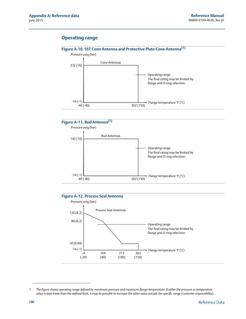
Reference Manual00809-0100-4026, Rev JA
Appendix A: Reference dataJune 2015
Operating range
Figure A-10. SST Cone Antenna and Protective Plate Cone Antenna(1)
Figure A-11. Rod Antenna(1)
Figure A-12. Process Seal Antenna
1. The figure shows operating range defined by maximum pressure and maximum flange temperature. If either the pressure or temperature value is kept lower than the defined limit, it may be possible to increase the other value outside the specific range (customer responsibility).
Pressure psig (bar)
Flange temperature °F (°C)-40 (-40) 302 (150)
Cone Antennas
-14 (-1)
232 (16)
Operating rangeThe final rating may be limited by flange and O-ring selection.
Pressure psig (bar)
Flange temperature °F (°C)-40 (-40) 302 (150)
Rod Antennas
-14 (-1)
145 (10)
Operating rangeThe final rating may be limited by flange and O-ring selection.
Pressure psig (bar)
Flange temperature °F (°C)-4
(-20)302
(150)
Process Seal Antennas
-14 (-1)
120 (8.2)
Operating rangeThe final rating may be limited by flange and O-ring selection.
104(40)
212(100)
10 (0.69)
90 (6.2)
190 Reference Data
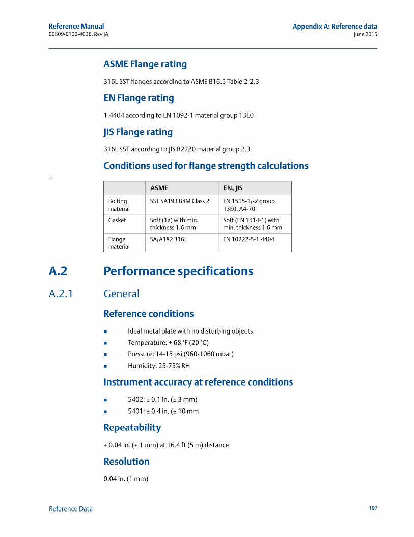
Reference Manual 00809-0100-4026, Rev JA
Appendix A: Reference dataJune 2015
ASME Flange rating
316L SST flanges according to ASME B16.5 Table 2-2.3
EN Flange rating
1.4404 according to EN 1092-1 material group 13E0
JIS Flange rating
316L SST according to JIS B2220 material group 2.3
Conditions used for flange strength calculations.
A.2 Performance specifications
A.2.1 General
Reference conditions
Ideal metal plate with no disturbing objects.
Temperature: + 68 °F (20 °C)
Pressure: 14-15 psi (960-1060 mbar)
Humidity: 25-75% RH
Instrument accuracy at reference conditions
5402: ± 0.1 in. (± 3 mm)
5401: ± 0.4 in. (± 10 mm
Repeatability
± 0.04 in. (± 1 mm) at 16.4 ft (5 m) distance
Resolution
0.04 in. (1 mm)
ASME EN, JIS
Bolting material
SST SA193 B8M Class 2 EN 1515-1/-2 group 13E0, A4-70
Gasket Soft (1a) with min. thickness 1.6 mm
Soft (EN 1514-1) with min. thickness 1.6 mm
Flange material
SA/A182 316L EN 10222-5-1.4404
191Reference Data
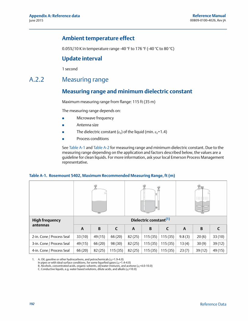
Reference Manual00809-0100-4026, Rev JA
Appendix A: Reference dataJune 2015
Ambient temperature effect
0.05%/10 K in temperature range -40 °F to 176 °F (-40 °C to 80 °C)
Update interval
1 second
A.2.2 Measuring range
Measuring range and minimum dielectric constant
Maximum measuring range from flange: 115 ft (35 m)
The measuring range depends on:
Microwave frequency
Antenna size
The dielectric constant (r) of the liquid (min. r=1.4)
Process conditions
See Table A-1 and Table A-2 for measuring range and minimum dielectric constant. Due to the measuring range depending on the application and factors described below, the values are a guideline for clean liquids. For more information, ask your local Emerson Process Management representative.
Table A-1. Rosemount 5402, Maximum Recommended Measuring Range, ft (m)
High frequency antennas
Dielectric constant(1)
1. A. Oil, gasoline or other hydrocarbons, and petrochemicals (r=1.9-4.0)In pipes or with ideal surface conditions, for some liquefied gases (r=1.4-4.0)B. Alcohols, concentrated acids, organic solvents, oil/water mixtures, and acetone (r=4.0-10.0)C. Conductive liquids, e.g. water based solutions, dilute acids, and alkalis (r>10.0)
A B C A B C A B C
2-in. Cone / Process Seal 33 (10) 49 (15) 66 (20) 82 (25) 115 (35) 115 (35) 9.8 (3) 20 (6) 33 (10)
3-in. Cone / Process Seal 49 (15) 66 (20) 98 (30) 82 (25) 115 (35) 115 (35) 13 (4) 30 (9) 39 (12)
4-in. Cone / Process Seal 66 (20) 82 (25) 115 (35) 82 (25) 115 (35) 115 (35) 23 (7) 39 (12) 49 (15)
192 Reference Data
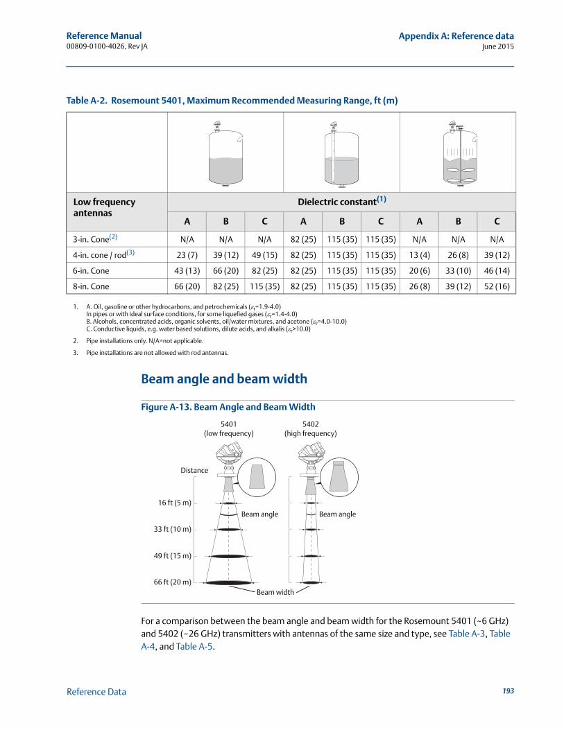
Reference Manual 00809-0100-4026, Rev JA
Appendix A: Reference dataJune 2015
Beam angle and beam width
Figure A-13. Beam Angle and Beam Width
For a comparison between the beam angle and beam width for the Rosemount 5401 (~6 GHz) and 5402 (~26 GHz) transmitters with antennas of the same size and type, see Table A-3, Table A-4, and Table A-5.
Table A-2. Rosemount 5401, Maximum Recommended Measuring Range, ft (m)
Low frequency antennas
Dielectric constant(1)
1. A. Oil, gasoline or other hydrocarbons, and petrochemicals (r=1.9-4.0)In pipes or with ideal surface conditions, for some liquefied gases (r=1.4-4.0)B. Alcohols, concentrated acids, organic solvents, oil/water mixtures, and acetone (r=4.0-10.0)C. Conductive liquids, e.g. water based solutions, dilute acids, and alkalis (r>10.0)
A B C A B C A B C
3-in. Cone(2)
2. Pipe installations only. N/A=not applicable.
N/A N/A N/A 82 (25) 115 (35) 115 (35) N/A N/A N/A
4-in. cone / rod(3)
3. Pipe installations are not allowed with rod antennas.
23 (7) 39 (12) 49 (15) 82 (25) 115 (35) 115 (35) 13 (4) 26 (8) 39 (12)
6-in. Cone 43 (13) 66 (20) 82 (25) 82 (25) 115 (35) 115 (35) 20 (6) 33 (10) 46 (14)
8-in. Cone 66 (20) 82 (25) 115 (35) 82 (25) 115 (35) 115 (35) 26 (8) 39 (12) 52 (16)
5401(low frequency)
16 ft (5 m)
5402(high frequency)
Distance
33 ft (10 m)
49 ft (15 m)
66 ft (20 m)
Beam angle Beam angle
Beam width
193Reference Data
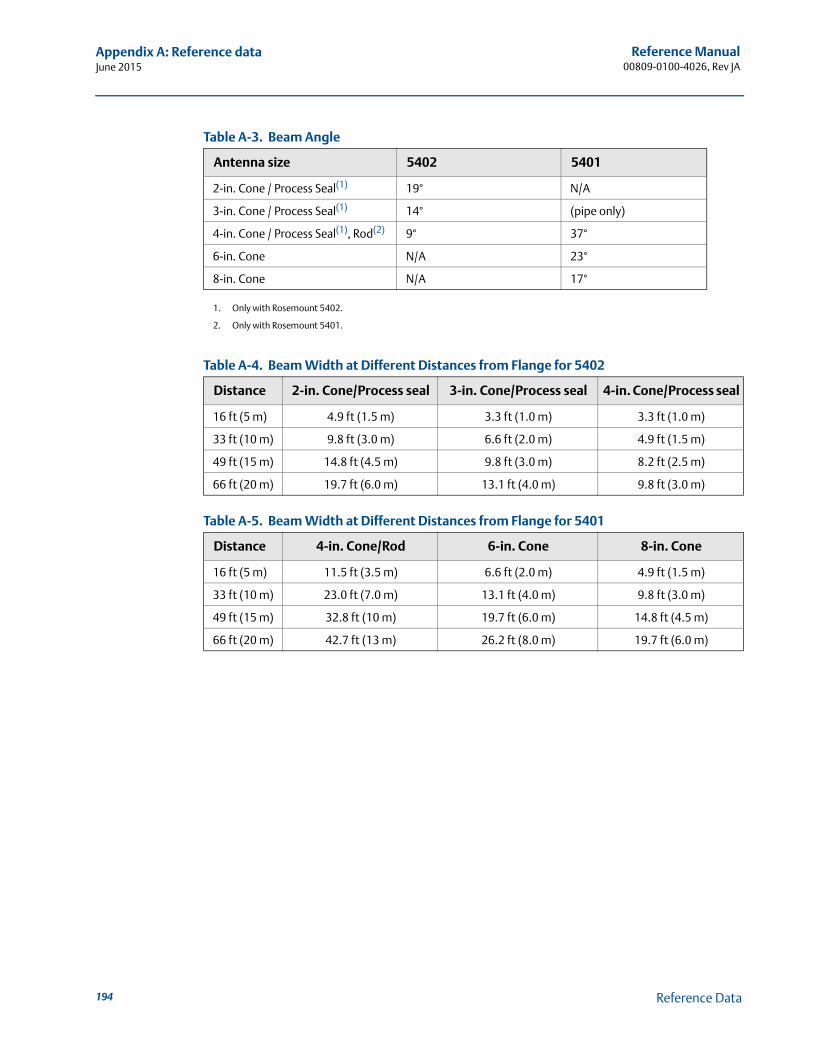
Reference Manual00809-0100-4026, Rev JA
Appendix A: Reference dataJune 2015
Table A-3. Beam Angle
Antenna size 5402 5401
2-in. Cone / Process Seal(1)
1. Only with Rosemount 5402.
19° N/A
3-in. Cone / Process Seal(1) 14° (pipe only)
4-in. Cone / Process Seal(1), Rod(2)
2. Only with Rosemount 5401.
9° 37°
6-in. Cone N/A 23°
8-in. Cone N/A 17°
Table A-4. Beam Width at Different Distances from Flange for 5402
Distance 2-in. Cone/Process seal 3-in. Cone/Process seal 4-in. Cone/Process seal
16 ft (5 m) 4.9 ft (1.5 m) 3.3 ft (1.0 m) 3.3 ft (1.0 m)
33 ft (10 m) 9.8 ft (3.0 m) 6.6 ft (2.0 m) 4.9 ft (1.5 m)
49 ft (15 m) 14.8 ft (4.5 m) 9.8 ft (3.0 m) 8.2 ft (2.5 m)
66 ft (20 m) 19.7 ft (6.0 m) 13.1 ft (4.0 m) 9.8 ft (3.0 m)
Table A-5. Beam Width at Different Distances from Flange for 5401
Distance 4-in. Cone/Rod 6-in. Cone 8-in. Cone
16 ft (5 m) 11.5 ft (3.5 m) 6.6 ft (2.0 m) 4.9 ft (1.5 m)
33 ft (10 m) 23.0 ft (7.0 m) 13.1 ft (4.0 m) 9.8 ft (3.0 m)
49 ft (15 m) 32.8 ft (10 m) 19.7 ft (6.0 m) 14.8 ft (4.5 m)
66 ft (20 m) 42.7 ft (13 m) 26.2 ft (8.0 m) 19.7 ft (6.0 m)
194 Reference Data
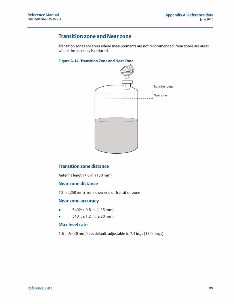
Reference Manual 00809-0100-4026, Rev JA
Appendix A: Reference dataJune 2015
Transition zone and Near zone
Transition zones are areas where measurements are not recommended. Near zones are areas where the accuracy is reduced.
Figure A-14. Transition Zone and Near Zone
Transition zone distance
Antenna length + 6 in. (150 mm)
Near zone distance
10 in. (250 mm) from lower end of Transition zone
Near zone accuracy
5402: ± 0.6 in. (± 15 mm)
5401: ± 1.2 in. (± 30 mm)
Max level rate
1.6 in./s (40 mm/s) as default, adjustable to 7.1 in./s (180 mm/s)
Transition zone
Near zone
195Reference Data
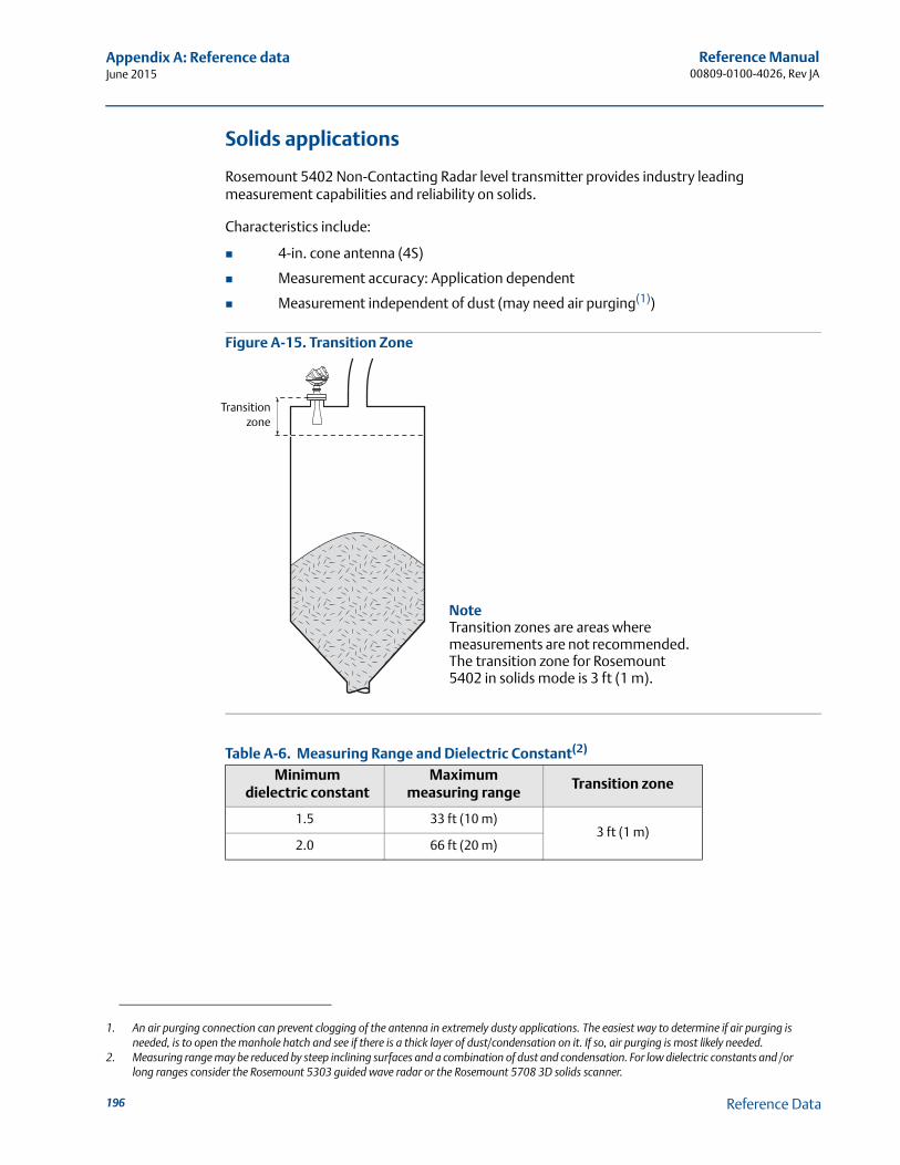
Reference Manual00809-0100-4026, Rev JA
Appendix A: Reference dataJune 2015
Solids applications
Rosemount 5402 Non-Contacting Radar level transmitter provides industry leading measurement capabilities and reliability on solids.
Characteristics include:
4-in. cone antenna (4S)
Measurement accuracy: Application dependent
Measurement independent of dust (may need air purging(1))
Figure A-15. Transition Zone
Table A-6. Measuring Range and Dielectric Constant(2)
1. An air purging connection can prevent clogging of the antenna in extremely dusty applications. The easiest way to determine if air purging is needed, is to open the manhole hatch and see if there is a thick layer of dust/condensation on it. If so, air purging is most likely needed.
Minimum dielectric constant
Maximum measuring range
Transition zone
1.5 33 ft (10 m)3 ft (1 m)
2.0 66 ft (20 m)
2. Measuring range may be reduced by steep inclining surfaces and a combination of dust and condensation. For low dielectric constants and /or long ranges consider the Rosemount 5303 guided wave radar or the Rosemount 5708 3D solids scanner.
Transitionzone
NoteTransition zones are areas where measurements are not recommended. The transition zone for Rosemount 5402 in solids mode is 3 ft (1 m).
196 Reference Data

Reference Manual 00809-0100-4026, Rev JA
Appendix A: Reference dataJune 2015
A.2.3 Environment
Vibration resistance(1)
Aluminum housing: IEC 60770-1 Level 1
SST housing: IACS E10
Electromagnetic compatibility(1)
Emission and immunity: EMC directive 204/108/EC. EN 61326-1:2006(2).
NAMUR recommendations NE21(2).
Built-in lightning protection
EN 61326, IEC 61000-4-5, level 2kV (6kV with T1 terminal block)
Pressure Equipment Directive (PED)
Complies with 97/23/EC article 3.3
Radio approvals(3)(4)
FCC part 15C (1998)(5), R&TTE (EU directive 99/5/EC), and IC (RSS210-5)
1. The device may also comply with other standards. Consult your local Emerson Process Management representative.2. Additional deviations at strong electromagnetic fields (NAMUR NE21) at specific frequencies are less than ± 1.6 in. (40 mm).3. Only a limited selection is presented. Contact your local Emerson Process Management representative for more information.4. For Japan: “Install device on tanks or pipes made of metal”.5. For 5402: “This device is authorized for use in tank-mounted applications, including metal tanks as well as concrete, plastic, glass, and other
non-conductive tanks.” No specific restrictions are stated for the 5401.
197Reference Data
Reference Manual00809-0100-4026, Rev JA
Appendix A: Reference dataJune 2015
A.3 Physical specifications
A.3.1 Material selection
Emerson provides a variety of Rosemount product with various product options and configurations including materials of construction that can be expected to perform well in a wide range of applications. The Rosemount product information presented is intended as a guide for the purchaser to make an appropriate selection for the application. It is the purchaser’s sole responsibility to make a careful analysis of all process parameters (such as all chemical components, temperature, pressure, flow rate, abrasives, contaminants, etc.), when specifying product, materials, options and components for the particular application. Emerson Process Management is not in a position to evaluate or guarantee the compatibility of the process fluid or other process parameters with the product, options, configuration or materials of construction selected.
A.3.2 Housing and closure
Product
Rosemount 5400 Series, Non-Contacting Radar
Type
Dual compartment (terminal compartment and the electronics are completely separated). Two entries for conduit or cable connections. The transmitter housing can be rotated in any direction.
Electrical connection
½ - 14 NPT for cable glands or conduit entries. Optional: M20 x 1.5 conduit / cable adapter, M12 4-pin male eurofast® connector or A size Mini 4-pin male minifast® connector. Recommended output cabling is twisted shielded pairs, 18-12 AWG.
Housing material
Polyurethane-covered Aluminum, or Stainless Steel Grade CF8M (ASTM A743)
Ingress protection
Type 4X, IP66, IP67
Factory sealed
Yes
Weight
Aluminum transmitter head: 4.4 lb (2 kg)
Stainless steel transmitter head: 10.8 lb (4.9 kg)
198 Reference Data
Reference Manual 00809-0100-4026, Rev JA
Appendix A: Reference dataJune 2015
A.3.3 Engineered solutions
When standard model codes are not sufficient to fulfill requirements, please consult the factory to explore possible Engineered Solutions. This is typically, but not exclusively, related to the choice of wetted materials or the design of a process connection. These Engineered Solutions are part of the expanded offerings and may be subject to additional delivery lead time. For ordering, factory will supply a special R-labeled numeric option code that should be added at the end of the standard model string. See example model string below.
Example Model String: 5402-A-H-1-E5-45-PV-CA-M1C1-R1234
A.3.4 Tank connection and antennas
Tank connection
The tank connection consists of a tank seal, a flange, Tri Clamp, or NPT thread.
Certain models of tank connections have a tank connection design with a protective plate of the same material as the antenna. This is to prevent the 316L / EN1.4404 stainless steel flange from being exposed to the tank atmosphere. See “Dimensional drawings and mechanical properties” on page 202.
Flange dimensions
Follows ASME B16.5, JIS B2220, and EN 1092-1 standards. For more information, see “Standard flanges” on page 207.
Antennas
Cone, Process Seal, and Rod Antenna. Cone antennas can be ordered in different materials. Extended cone antennas are available in SST 316L.
5402 Cone Antenna
Suitable for stilling-well/bridle installation
Can be recessed in smooth nozzles
Cone extensions are available
Suitable for solids applications (only 4 inch cone antenna)
5402 Process Seal Antenna
Ideal for small tanks and corrosive applications
Suitable for applications with heavy condensation/build-up
5401 Cone Antenna
Suitable for applications with heavy condensation/build-up
Cone extensions are available
5401 Rod Antenna
Suitable for small process connections and corrosive environments
Two versions: all PFA and PFA+SST
199Reference Data
Reference Manual00809-0100-4026, Rev JA
Appendix A: Reference dataJune 2015
Antenna dimensions
Cone antenna: See “Rosemount 5402 and 5401 with SST Cone Antenna (Model Code: 2S-8S)” on page 202 and “Rosemount 5402 and 5401 with Protective Plate Cone Antenna (Model Code: 2H-8H, 2M-8M, and 2N-8N)” on page 203.
Rod antenna: See “Rosemount 5401 with Rod Antenna (Model Code: 1R-4R)” on page 204.
Process Seal Antenna: See “Rosemount 5402 with Process Seal Antenna (Model Code: 2P-4P)” on page 205.
Material exposed to tank atmosphere
Cone Antenna
316 / 316 L SST (EN 1.4404) or Alloy 400 (UNS NO4400) or Alloy C-276 (UNS N10276). Alloy 400 and Alloy C-276 antennas have a protective plate design
PTFE fluoropolymer
O-ring material
Rod Antenna, two versions
All-PFA(1) fluoropolymer
PFA(1) fluoropolymer, 316 / 316 L SST (EN 1.4404) and O-ring material
Process Seal Antenna
PTFE fluoropolymer
1. PFA is a fluoropolymer with properties similar to PTFE.
200 Reference Data
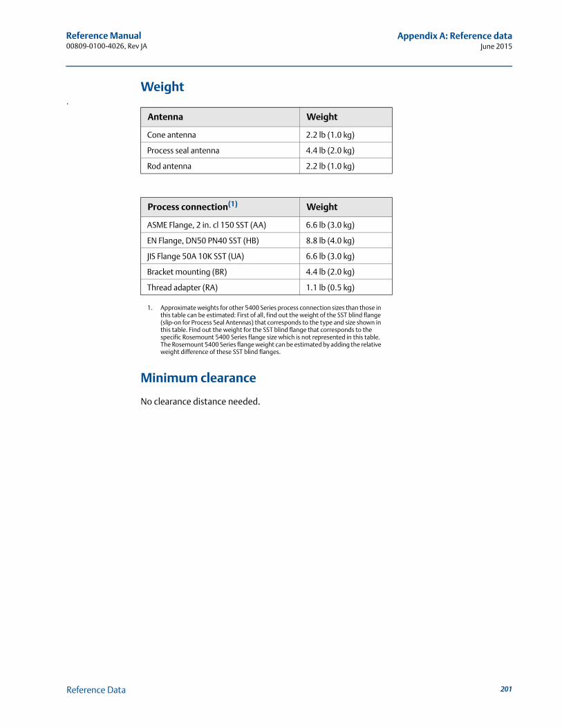
Reference Manual 00809-0100-4026, Rev JA
Appendix A: Reference dataJune 2015
Weight.
Minimum clearance
No clearance distance needed.
Antenna Weight
Cone antenna 2.2 lb (1.0 kg)
Process seal antenna 4.4 lb (2.0 kg)
Rod antenna 2.2 lb (1.0 kg)
Process connection(1)
1. Approximate weights for other 5400 Series process connection sizes than those in this table can be estimated: First of all, find out the weight of the SST blind flange (slip-on for Process Seal Antennas) that corresponds to the type and size shown in this table. Find out the weight for the SST blind flange that corresponds to the specific Rosemount 5400 Series flange size which is not represented in this table. The Rosemount 5400 Series flange weight can be estimated by adding the relative weight difference of these SST blind flanges.
Weight
ASME Flange, 2 in. cl 150 SST (AA) 6.6 lb (3.0 kg)
EN Flange, DN50 PN40 SST (HB) 8.8 lb (4.0 kg)
JIS Flange 50A 10K SST (UA) 6.6 lb (3.0 kg)
Bracket mounting (BR) 4.4 lb (2.0 kg)
Thread adapter (RA) 1.1 lb (0.5 kg)
201Reference Data
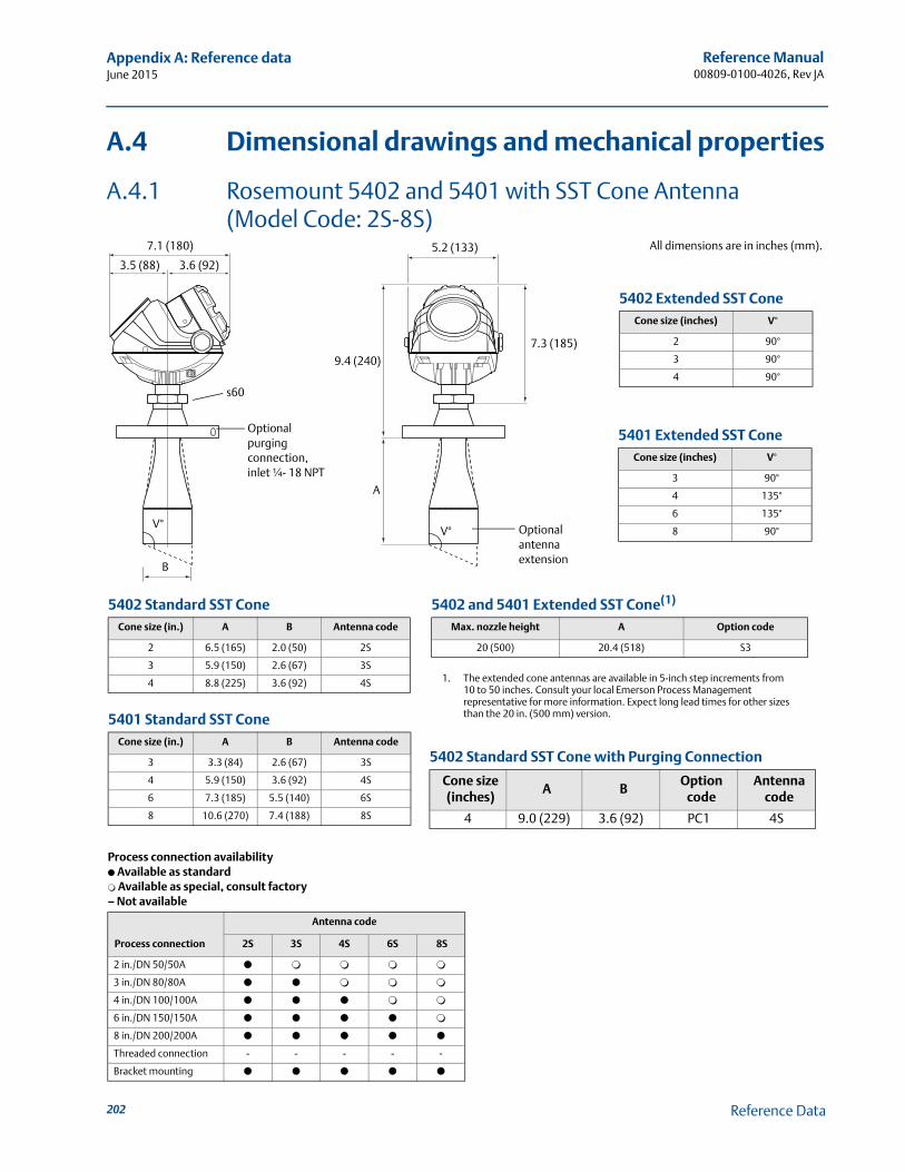
Reference Manual00809-0100-4026, Rev JA
Appendix A: Reference dataJune 2015
A.4 Dimensional drawings and mechanical properties
A.4.1 Rosemount 5402 and 5401 with SST Cone Antenna (Model Code: 2S-8S)
7.1 (180)
3.5 (88) 3.6 (92)
s60
B
V°
5.2 (133)
9.4 (240)
A
7.3 (185)
V° Optional antenna extension
All dimensions are in inches (mm).
Process connection availability● Available as standard❍ Available as special, consult factory– Not available
Process connection
Antenna code
2S 3S 4S 6S 8S
2 in./DN 50/50A ● ❍ ❍ ❍ ❍
3 in./DN 80/80A ● ● ❍ ❍ ❍
4 in./DN 100/100A ● ● ● ❍ ❍
6 in./DN 150/150A ● ● ● ● ❍
8 in./DN 200/200A ● ● ● ● ●
Threaded connection - - - - -
Bracket mounting ● ● ● ● ●
5402 Standard SST ConeCone size (in.) A B Antenna code
2 6.5 (165) 2.0 (50) 2S
3 5.9 (150) 2.6 (67) 3S
4 8.8 (225) 3.6 (92) 4S
5401 Standard SST ConeCone size (in.) A B Antenna code
3 3.3 (84) 2.6 (67) 3S
4 5.9 (150) 3.6 (92) 4S
6 7.3 (185) 5.5 (140) 6S
8 10.6 (270) 7.4 (188) 8S
5402 and 5401 Extended SST Cone(1)
1. The extended cone antennas are available in 5-inch step increments from 10 to 50 inches. Consult your local Emerson Process Management representative for more information. Expect long lead times for other sizes than the 20 in. (500 mm) version.
Max. nozzle height A Option code
20 (500) 20.4 (518) S3
5402 Extended SST ConeCone size (inches) V°
2 90°
3 90°
4 90°
5401 Extended SST ConeCone size (inches) V°
3 90°
4 135°
6 135°
8 90°
5402 Standard SST Cone with Purging Connection
Cone size (inches)
A BOption
codeAntenna
code
4 9.0 (229) 3.6 (92) PC1 4S
Optional purging connection, inlet ¼- 18 NPT
202 Reference Data
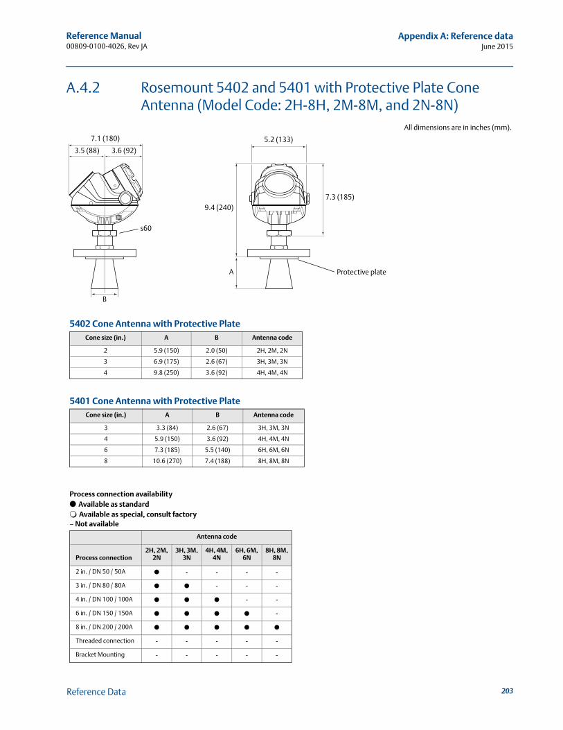
Reference Manual 00809-0100-4026, Rev JA
Appendix A: Reference dataJune 2015
A.4.2 Rosemount 5402 and 5401 with Protective Plate Cone Antenna (Model Code: 2H-8H, 2M-8M, and 2N-8N)
7.1 (180)
3.5 (88) 3.6 (92)
s60
B
5.2 (133)
9.4 (240)
A
7.3 (185)
All dimensions are in inches (mm).
Protective plate
5402 Cone Antenna with Protective PlateCone size (in.) A B Antenna code
2 5.9 (150) 2.0 (50) 2H, 2M, 2N
3 6.9 (175) 2.6 (67) 3H, 3M, 3N
4 9.8 (250) 3.6 (92) 4H, 4M, 4N
Process connection availability● Available as standard❍ Available as special, consult factory– Not available
Antenna code
Process connection2H, 2M,
2N3H, 3M,
3N4H, 4M,
4N6H, 6M,
6N8H, 8M,
8N
2 in. / DN 50 / 50A ● - - - -
3 in. / DN 80 / 80A ● ● - - -
4 in. / DN 100 / 100A ● ● ● - -
6 in. / DN 150 / 150A ● ● ● ● -
8 in. / DN 200 / 200A ● ● ● ● ●
Threaded connection - - - - -
Bracket Mounting - - - - -
5401 Cone Antenna with Protective PlateCone size (in.) A B Antenna code
3 3.3 (84) 2.6 (67) 3H, 3M, 3N
4 5.9 (150) 3.6 (92) 4H, 4M, 4N
6 7.3 (185) 5.5 (140) 6H, 6M, 6N
8 10.6 (270) 7.4 (188) 8H, 8M, 8N
203Reference Data
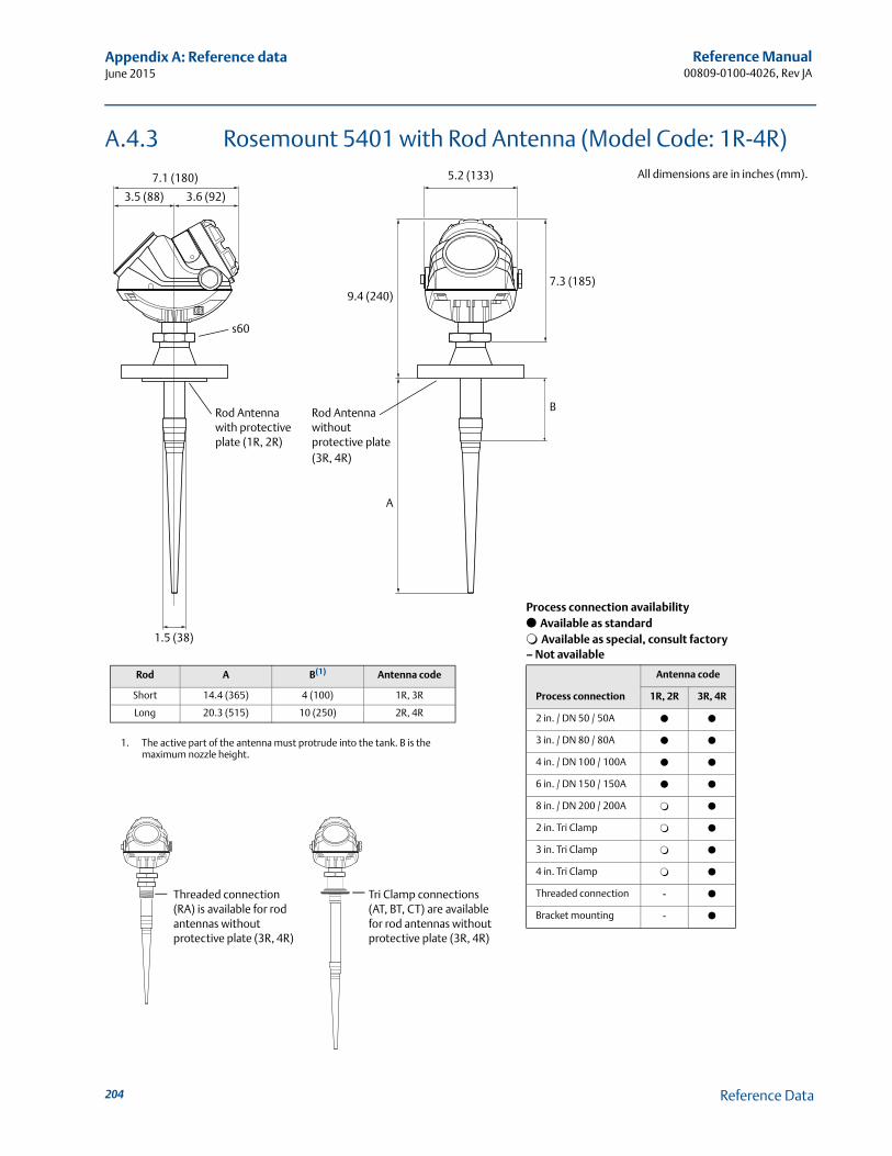
Reference Manual00809-0100-4026, Rev JA
Appendix A: Reference dataJune 2015
A.4.3 Rosemount 5401 with Rod Antenna (Model Code: 1R-4R)
7.1 (180)
3.5 (88) 3.6 (92)
s60
5.2 (133)
9.4 (240)7.3 (185)
All dimensions are in inches (mm).
Rod Antenna with protective plate (1R, 2R)
Rod Antenna without protective plate(3R, 4R)
B
A
1.5 (38)
Tri Clamp connections (AT, BT, CT) are available for rod antennas without protective plate (3R, 4R)
Rod A B(1)
1. The active part of the antenna must protrude into the tank. B is the maximum nozzle height.
Antenna code
Short 14.4 (365) 4 (100) 1R, 3R
Long 20.3 (515) 10 (250) 2R, 4R
Process connection availability● Available as standard❍ Available as special, consult factory– Not available
Process connection
Antenna code
1R, 2R 3R, 4R
2 in. / DN 50 / 50A ● ●
3 in. / DN 80 / 80A ● ●
4 in. / DN 100 / 100A ● ●
6 in. / DN 150 / 150A ● ●
8 in. / DN 200 / 200A ❍ ●
2 in. Tri Clamp ❍ ●
3 in. Tri Clamp ❍ ●
4 in. Tri Clamp ❍ ●
Threaded connection - ●
Bracket mounting - ●
Threaded connection (RA) is available for rod antennas without protective plate (3R, 4R)
204 Reference Data
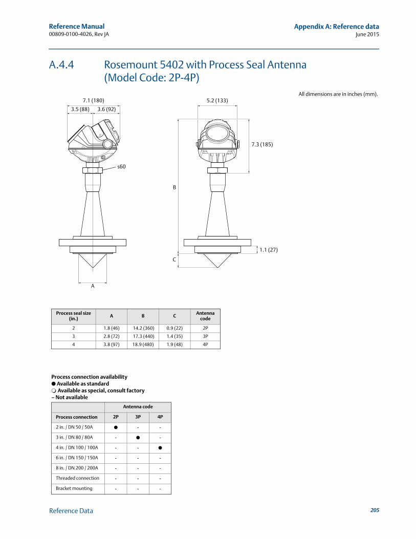
Reference Manual 00809-0100-4026, Rev JA
Appendix A: Reference dataJune 2015
A.4.4 Rosemount 5402 with Process Seal Antenna (Model Code: 2P-4P)
All dimensions are in inches (mm).7.1 (180)
3.5 (88) 3.6 (92)
s60
A
B
C
5.2 (133)
7.3 (185)
1.1 (27)
Process seal size (in.) A B C Antenna
code
2 1.8 (46) 14.2 (360) 0.9 (22) 2P
3 2.8 (72) 17.3 (440) 1.4 (35) 3P
4 3.8 (97) 18.9 (480) 1.9 (48) 4P
Process connection availability● Available as standard❍ Available as special, consult factory– Not available
Antenna code
Process connection 2P 3P 4P
2 in. / DN 50 / 50A ● - -
3 in. / DN 80 / 80A - ● -
4 in. / DN 100 / 100A - - ●
6 in. / DN 150 / 150A - - -
8 in. / DN 200 / 200A - - -
Threaded connection - - -
Bracket mounting - - -
205Reference Data
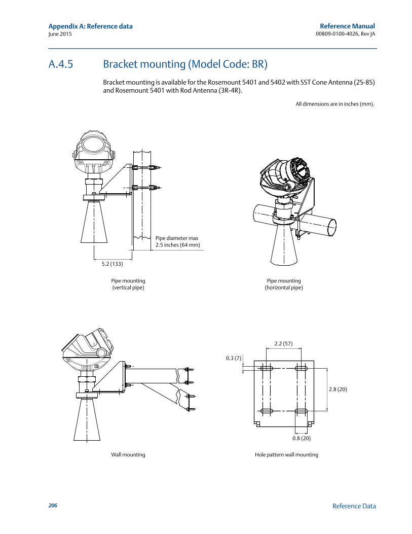
Reference Manual00809-0100-4026, Rev JA
Appendix A: Reference dataJune 2015
A.4.5 Bracket mounting (Model Code: BR)
Bracket mounting is available for the Rosemount 5401 and 5402 with SST Cone Antenna (2S-8S) and Rosemount 5401 with Rod Antenna (3R-4R).
All dimensions are in inches (mm).
Pipe mounting(vertical pipe)
Pipe mounting(horizontal pipe)
Pipe diameter max 2.5 inches (64 mm)
5.2 (133)
Wall mounting Hole pattern wall mounting
0.3 (7)
2.2 (57)
0.8 (20)
2.8 (20)
206 Reference Data

Reference Manual 00809-0100-4026, Rev JA
Appendix A: Reference dataJune 2015
A.4.6 Process connections
Standard flanges
Cone and Rod antennas (model code: 2S-8S and 1R-4R)
Cone antennas with protective plate (model code: 2H-8H, 2M-8M, and 2N-8N)
Process Seal Antennas
Designation Mating standard Face style(1)
1. Face gasket surface is serrated per mating standard.
Face surface finish Material
ASME ASME B16.5 0.06 in. raised face Ra = 125-250 μin 316/316L
EN EN 1092-1 2 mm raised face (Type B1) Ra = 3.2-12.5 μm EN 1.4404
JIS JIS B2220 2 mm raised face Ra = 3.2-6.3 μm EN 1.4404
Designation Mating standardFace style including protective plate
Plate surface finish Material
ASME ASME B16.5 Raised face Ra = 3.2-6.3 μm 316/316L
EN EN 1092-1 Raised face Ra = 3.2-6.3 μm EN 1.4404
JIS JIS B2220 Raised face Ra = 3.2-6.3 μm EN 1.4404
Designation Standard Style Material
ASME ASME B16.5 Slip-on 316/316L
EN EN 1092-1 Slip-on (Type 01) EN 1.4404
JIS JIS B2220 Slip-on plate (SOP) EN 1.4404
207Reference Data
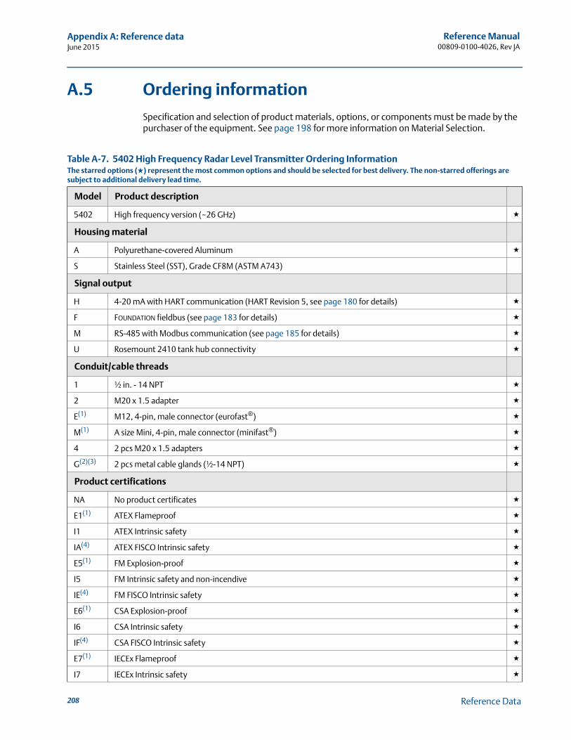
Reference Manual00809-0100-4026, Rev JA
Appendix A: Reference dataJune 2015
A.5 Ordering information
Specification and selection of product materials, options, or components must be made by the purchaser of the equipment. See page 198 for more information on Material Selection.
Table A-7. 5402 High Frequency Radar Level Transmitter Ordering InformationThe starred options (★) represent the most common options and should be selected for best delivery. The non-starred offerings are subject to additional delivery lead time.
Model Product description
5402 High frequency version (~26 GHz) ★
Housing material
A Polyurethane-covered Aluminum ★
S Stainless Steel (SST), Grade CF8M (ASTM A743)
Signal output
H 4-20 mA with HART communication (HART Revision 5, see page 180 for details) ★
F FOUNDATION fieldbus (see page 183 for details) ★
M RS-485 with Modbus communication (see page 185 for details) ★
U Rosemount 2410 tank hub connectivity ★
Conduit/cable threads
1 ½ in. - 14 NPT ★
2 M20 x 1.5 adapter ★
E(1) M12, 4-pin, male connector (eurofast®) ★
M(1) A size Mini, 4-pin, male connector (minifast®) ★
4 2 pcs M20 x 1.5 adapters ★
G(2)(3) 2 pcs metal cable glands (½-14 NPT) ★
Product certifications
NA No product certificates ★
E1(1) ATEX Flameproof ★
I1 ATEX Intrinsic safety ★
IA(4) ATEX FISCO Intrinsic safety ★
E5(1) FM Explosion-proof ★
I5 FM Intrinsic safety and non-incendive ★
IE(4) FM FISCO Intrinsic safety ★
E6(1) CSA Explosion-proof ★
I6 CSA Intrinsic safety ★
IF(4) CSA FISCO Intrinsic safety ★
E7(1) IECEx Flameproof ★
I7 IECEx Intrinsic safety ★
208 Reference Data
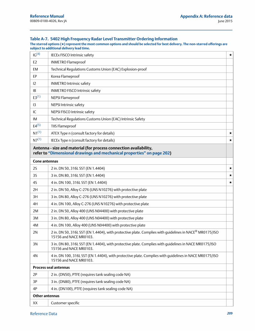
Reference Manual 00809-0100-4026, Rev JA
Appendix A: Reference dataJune 2015
IG(4) IECEx FISCO Intrinsic safety ★
E2 INMETRO Flameproof
EM Technical Regulations Customs Union (EAC) Explosion-proof
EP Korea Flameproof
I2 INMETRO Intrinsic safety
IB INMETRO FISCO Intrinsic safety
E3(1) NEPSI Flameproof
I3 NEPSI Intrinsic safety
IC NEPSI FISCO Intrinsic safety
IM Technical Regulations Customs Union (EAC) Intrinsic Safety
E4(5) TIIS Flameproof
N1(1) ATEX Type n (consult factory for details) ★
N7(1) IECEx Type n (consult factory for details) ★
Antenna - size and material (for process connection availability,refer to “Dimensional drawings and mechanical properties” on page 202)
Cone antennas
2S 2 in. DN 50, 316L SST (EN 1.4404) ★
3S 3 in. DN 80, 316L SST (EN 1.4404) ★
4S 4 in. DN 100, 316L SST (EN 1.4404) ★
2H 2 in. DN 50, Alloy C-276 (UNS N10276) with protective plate
3H 3 in. DN 80, Alloy C-276 (UNS N10276) with protective plate
4H 4 in. DN 100, Alloy C-276 (UNS N10276) with protective plate
2M 2 in. DN 50, Alloy 400 (UNS N04400) with protective plate
3M 3 in. DN 80, Alloy 400 (UNS N04400) with protective plate
4M 4 in. DN 100, Alloy 400 (UNS N04400) with protective plate
2N 2 in. DN 50, 316L SST (EN 1.4404), with protective plate. Complies with guidelines in NACE® MR0175/ISO 15156 and NACE MR0103.
3N 3 in. DN 80, 316L SST (EN 1.4404), with protective plate. Complies with guidelines in NACE MR0175/ISO 15156 and NACE MR0103.
4N 4 in. DN 100, 316L SST (EN 1.4404), with protective plate. Complies with guidelines in NACE MR0175/ISO 15156 and NACE MR0103.
Process seal antennas
2P 2 in. (DN50), PTFE (requires tank sealing code NA)
3P 3 in. (DN80), PTFE (requires tank sealing code NA)
4P 4 in. (DN100), PTFE (requires tank sealing code NA)
Other antennas
XX Customer specific
Table A-7. 5402 High Frequency Radar Level Transmitter Ordering InformationThe starred options (★) represent the most common options and should be selected for best delivery. The non-starred offerings are subject to additional delivery lead time.
209Reference Data
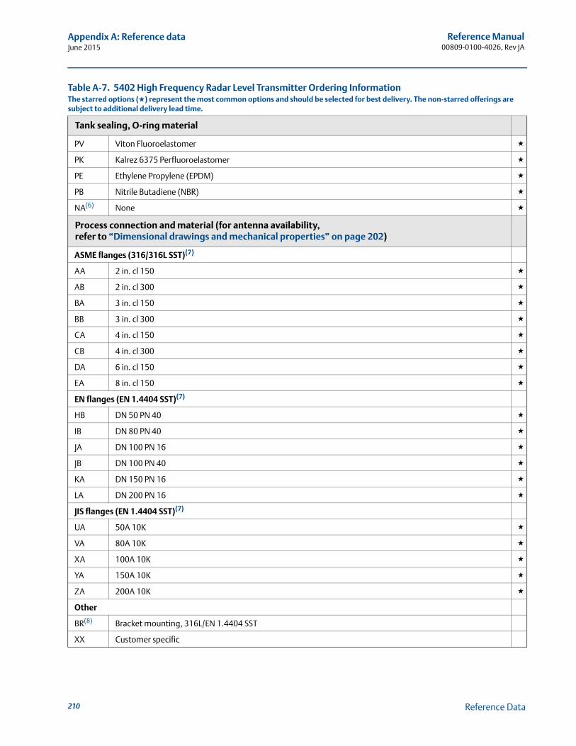
Reference Manual00809-0100-4026, Rev JA
Appendix A: Reference dataJune 2015
Tank sealing, O-ring material
PV Viton Fluoroelastomer ★
PK Kalrez 6375 Perfluoroelastomer ★
PE Ethylene Propylene (EPDM) ★
PB Nitrile Butadiene (NBR) ★
NA(6) None ★
Process connection and material (for antenna availability,refer to “Dimensional drawings and mechanical properties” on page 202)
ASME flanges (316/316L SST)(7)
AA 2 in. cl 150 ★
AB 2 in. cl 300 ★
BA 3 in. cl 150 ★
BB 3 in. cl 300 ★
CA 4 in. cl 150 ★
CB 4 in. cl 300 ★
DA 6 in. cl 150 ★
EA 8 in. cl 150 ★
EN flanges (EN 1.4404 SST)(7)
HB DN 50 PN 40 ★
IB DN 80 PN 40 ★
JA DN 100 PN 16 ★
JB DN 100 PN 40 ★
KA DN 150 PN 16 ★
LA DN 200 PN 16 ★
JIS flanges (EN 1.4404 SST)(7)
UA 50A 10K ★
VA 80A 10K ★
XA 100A 10K ★
YA 150A 10K ★
ZA 200A 10K ★
Other
BR(8) Bracket mounting, 316L/EN 1.4404 SST
XX Customer specific
Table A-7. 5402 High Frequency Radar Level Transmitter Ordering InformationThe starred options (★) represent the most common options and should be selected for best delivery. The non-starred offerings are subject to additional delivery lead time.
210 Reference Data
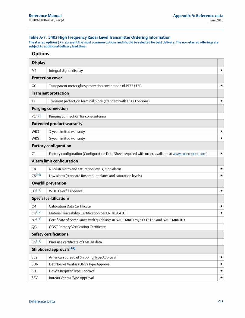
Reference Manual 00809-0100-4026, Rev JA
Appendix A: Reference dataJune 2015
Options
Display
M1 Integral digital display ★
Protection cover
GC Transparent meter glass protection cover made of PTFE / FEP ★
Transient protection
T1 Transient protection terminal block (standard with FISCO options) ★
Purging connection
PC1(9) Purging connection for cone antenna
Extended product warranty
WR3 3-year limited warranty ★
WR5 5-year limited warranty ★
Factory configuration
C1 Factory configuration (Configuration Data Sheet required with order, available at www.rosemount.com) ★
Alarm limit configuration
C4 NAMUR alarm and saturation levels, high alarm ★
C8(10) Low alarm (standard Rosemount alarm and saturation levels) ★
Overfill prevention
U1(11) WHG Overfill approval ★
Special certifications
Q4 Calibration Data Certificate ★
Q8(12) Material Traceability Certification per EN 10204 3.1 ★
N2(13) Certificate of compliance with guidelines in NACE MR0175/ISO 15156 and NACE MR0103
QG GOST Primary Verification Certificate
Safety certifications
QS(11) Prior use certificate of FMEDA data
Shipboard approvals(14)
SBS American Bureau of Shipping Type Approval ★
SDN Det Norske Veritas (DNV) Type Approval ★
SLL Lloyd's Register Type Approval ★
SBV Bureau Veritas Type Approval ★
Table A-7. 5402 High Frequency Radar Level Transmitter Ordering InformationThe starred options (★) represent the most common options and should be selected for best delivery. The non-starred offerings are subject to additional delivery lead time.
211Reference Data
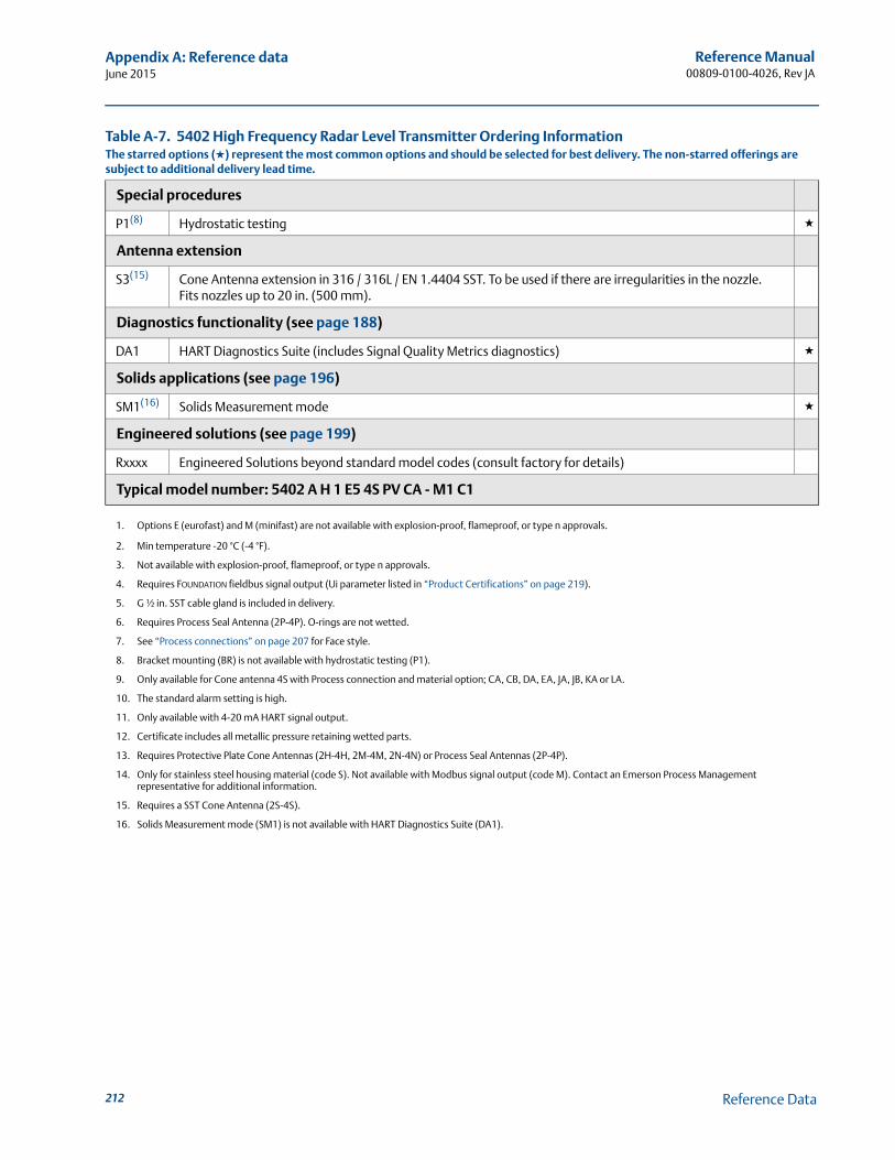
Reference Manual00809-0100-4026, Rev JA
Appendix A: Reference dataJune 2015
Special procedures
P1(8) Hydrostatic testing ★
Antenna extension
S3(15) Cone Antenna extension in 316 / 316L / EN 1.4404 SST. To be used if there are irregularities in the nozzle. Fits nozzles up to 20 in. (500 mm).
Diagnostics functionality (see page 188)
DA1 HART Diagnostics Suite (includes Signal Quality Metrics diagnostics) ★
Solids applications (see page 196)
SM1(16) Solids Measurement mode ★
Engineered solutions (see page 199)
Rxxxx Engineered Solutions beyond standard model codes (consult factory for details)
Typical model number: 5402 A H 1 E5 4S PV CA - M1 C1
1. Options E (eurofast) and M (minifast) are not available with explosion-proof, flameproof, or type n approvals.
2. Min temperature -20 °C (-4 °F).
3. Not available with explosion-proof, flameproof, or type n approvals.
4. Requires FOUNDATION fieldbus signal output (Ui parameter listed in “Product Certifications” on page 219).
5. G ½ in. SST cable gland is included in delivery.
6. Requires Process Seal Antenna (2P-4P). O-rings are not wetted.
7. See “Process connections” on page 207 for Face style.
8. Bracket mounting (BR) is not available with hydrostatic testing (P1).
9. Only available for Cone antenna 4S with Process connection and material option; CA, CB, DA, EA, JA, JB, KA or LA.
10. The standard alarm setting is high.
11. Only available with 4-20 mA HART signal output.
12. Certificate includes all metallic pressure retaining wetted parts.
13. Requires Protective Plate Cone Antennas (2H-4H, 2M-4M, 2N-4N) or Process Seal Antennas (2P-4P).
14. Only for stainless steel housing material (code S). Not available with Modbus signal output (code M). Contact an Emerson Process Management representative for additional information.
15. Requires a SST Cone Antenna (2S-4S).
16. Solids Measurement mode (SM1) is not available with HART Diagnostics Suite (DA1).
Table A-7. 5402 High Frequency Radar Level Transmitter Ordering InformationThe starred options (★) represent the most common options and should be selected for best delivery. The non-starred offerings are subject to additional delivery lead time.
212 Reference Data
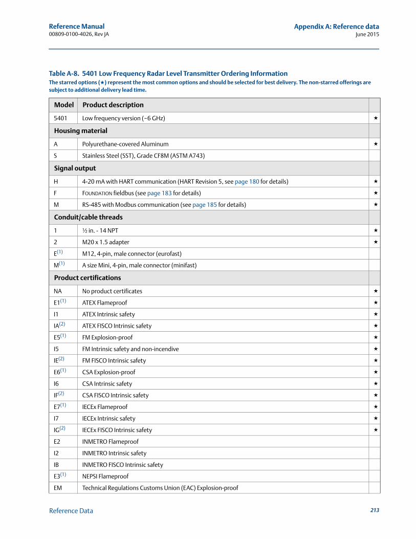
Reference Manual 00809-0100-4026, Rev JA
Appendix A: Reference dataJune 2015
Table A-8. 5401 Low Frequency Radar Level Transmitter Ordering InformationThe starred options (★) represent the most common options and should be selected for best delivery. The non-starred offerings are subject to additional delivery lead time.
Model Product description
5401 Low frequency version (~6 GHz) ★
Housing material
A Polyurethane-covered Aluminum ★
S Stainless Steel (SST), Grade CF8M (ASTM A743)
Signal output
H 4-20 mA with HART communication (HART Revision 5, see page 180 for details) ★
F FOUNDATION fieldbus (see page 183 for details) ★
M RS-485 with Modbus communication (see page 185 for details) ★
Conduit/cable threads
1 ½ in. - 14 NPT ★
2 M20 x 1.5 adapter ★
E(1) M12, 4-pin, male connector (eurofast)
M(1) A size Mini, 4-pin, male connector (minifast)
Product certifications
NA No product certificates ★
E1(1) ATEX Flameproof ★
I1 ATEX Intrinsic safety ★
IA(2) ATEX FISCO Intrinsic safety ★
E5(1) FM Explosion-proof ★
I5 FM Intrinsic safety and non-incendive ★
IE(2) FM FISCO Intrinsic safety ★
E6(1) CSA Explosion-proof ★
I6 CSA Intrinsic safety ★
IF(2) CSA FISCO Intrinsic safety ★
E7(1) IECEx Flameproof ★
I7 IECEx Intrinsic safety ★
IG(2) IECEx FISCO Intrinsic safety ★
E2 INMETRO Flameproof
I2 INMETRO Intrinsic safety
IB INMETRO FISCO Intrinsic safety
E3(1) NEPSI Flameproof
EM Technical Regulations Customs Union (EAC) Explosion-proof
213Reference Data
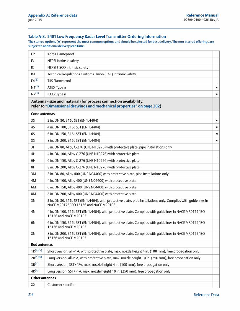
Reference Manual00809-0100-4026, Rev JA
Appendix A: Reference dataJune 2015
EP Korea Flameproof
I3 NEPSI Intrinsic safety
IC NEPSI FISCO Intrinsic safety
IM Technical Regulations Customs Union (EAC) Intrinsic Safety
E4(3) TIIS Flameproof
N1(1) ATEX Type n ★
N7(1) IECEx Type n ★
Antenna - size and material (for process connection availability,refer to “Dimensional drawings and mechanical properties” on page 202)
Cone antennas
3S 3 in. DN 80, 316L SST (EN 1.4404) ★
4S 4 in. DN 100, 316L SST (EN 1.4404) ★
6S 6 in. DN 150, 316L SST (EN 1.4404) ★
8S 8 in. DN 200, 316L SST (EN 1.4404) ★
3H 3 in. DN 80, Alloy C-276 (UNS N10276) with protective plate, pipe installations only
4H 4 in. DN 100, Alloy C-276 (UNS N10276) with protective plate
6H 6 in. DN 150, Alloy C-276 (UNS N10276) with protective plate
8H 8 in. DN 200, Alloy C-276 (UNS N10276) with protective plate
3M 3 in. DN 80, Alloy 400 (UNS N04400) with protective plate, pipe installations only
4M 4 in. DN 100, Alloy 400 (UNS N04400) with protective plate
6M 6 in. DN 150, Alloy 400 (UNS N04400) with protective plate
8M 8 in. DN 200, Alloy 400 (UNS N04400) with protective plate
3N 3 in. DN 80, 316L SST (EN 1.4404), with protective plate, pipe installations only. Complies with guidelines in NACE MR0175/ISO 15156 and NACE MR0103.
4N 4 in. DN 100, 316L SST (EN 1.4404), with protective plate. Complies with guidelines in NACE MR0175/ISO 15156 and NACE MR0103.
6N 6 in. DN 150, 316L SST (EN 1.4404), with protective plate. Complies with guidelines in NACE MR0175/ISO 15156 and NACE MR0103.
8N 8 in. DN 200, 316L SST (EN 1.4404), with protective plate. Complies with guidelines in NACE MR0175/ISO 15156 and NACE MR0103.
Rod antennas
1R(4)(5) Short version, all-PFA, with protective plate, max. nozzle height 4 in. (100 mm), free propagation only
2R(4)(5) Long version, all-PFA, with protective plate, max. nozzle height 10 in. (250 mm), free propagation only
3R(4) Short version, SST+PFA, max. nozzle height 4 in. (100 mm), free propagation only
4R(4) Long version, SST+PFA, max. nozzle height 10 in. (250 mm), free propagation only
Other antennas
XX Customer specific
Table A-8. 5401 Low Frequency Radar Level Transmitter Ordering InformationThe starred options (★) represent the most common options and should be selected for best delivery. The non-starred offerings are subject to additional delivery lead time.
214 Reference Data
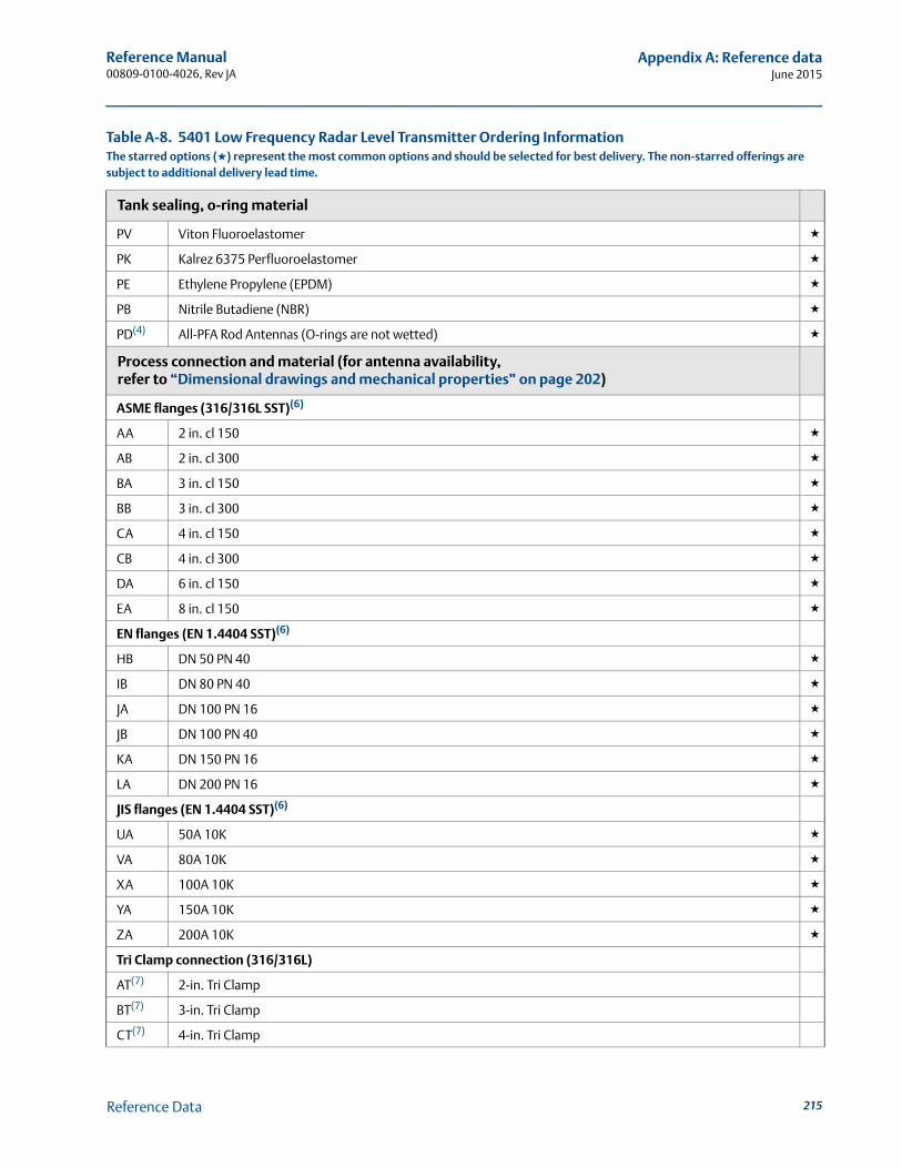
Reference Manual 00809-0100-4026, Rev JA
Appendix A: Reference dataJune 2015
Tank sealing, o-ring material
PV Viton Fluoroelastomer ★
PK Kalrez 6375 Perfluoroelastomer ★
PE Ethylene Propylene (EPDM) ★
PB Nitrile Butadiene (NBR) ★
PD(4) All-PFA Rod Antennas (O-rings are not wetted) ★
Process connection and material (for antenna availability,refer to “Dimensional drawings and mechanical properties” on page 202)
ASME flanges (316/316L SST)(6)
AA 2 in. cl 150 ★
AB 2 in. cl 300 ★
BA 3 in. cl 150 ★
BB 3 in. cl 300 ★
CA 4 in. cl 150 ★
CB 4 in. cl 300 ★
DA 6 in. cl 150 ★
EA 8 in. cl 150 ★
EN flanges (EN 1.4404 SST)(6)
HB DN 50 PN 40 ★
IB DN 80 PN 40 ★
JA DN 100 PN 16 ★
JB DN 100 PN 40 ★
KA DN 150 PN 16 ★
LA DN 200 PN 16 ★
JIS flanges (EN 1.4404 SST)(6)
UA 50A 10K ★
VA 80A 10K ★
XA 100A 10K ★
YA 150A 10K ★
ZA 200A 10K ★
Tri Clamp connection (316/316L)
AT(7) 2-in. Tri Clamp
BT(7) 3-in. Tri Clamp
CT(7) 4-in. Tri Clamp
Table A-8. 5401 Low Frequency Radar Level Transmitter Ordering InformationThe starred options (★) represent the most common options and should be selected for best delivery. The non-starred offerings are subject to additional delivery lead time.
215Reference Data
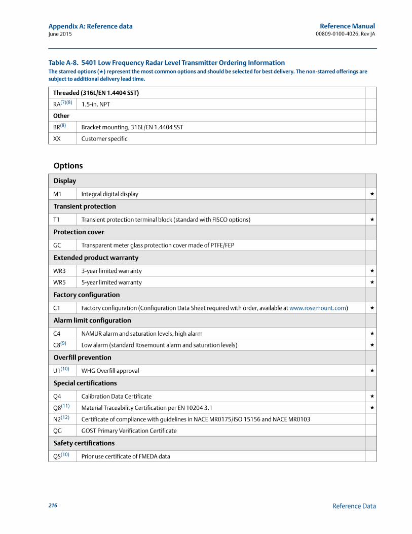
Reference Manual00809-0100-4026, Rev JA
Appendix A: Reference dataJune 2015
Threaded (316L/EN 1.4404 SST)
RA(7)(8) 1.5-in. NPT
Other
BR(8) Bracket mounting, 316L/EN 1.4404 SST
XX Customer specific
Options
Display
M1 Integral digital display ★
Transient protection
T1 Transient protection terminal block (standard with FISCO options) ★
Protection cover
GC Transparent meter glass protection cover made of PTFE/FEP
Extended product warranty
WR3 3-year limited warranty ★
WR5 5-year limited warranty ★
Factory configuration
C1 Factory configuration (Configuration Data Sheet required with order, available at www.rosemount.com) ★
Alarm limit configuration
C4 NAMUR alarm and saturation levels, high alarm ★
C8(9) Low alarm (standard Rosemount alarm and saturation levels) ★
Overfill prevention
U1(10) WHG Overfill approval ★
Special certifications
Q4 Calibration Data Certificate ★
Q8(11) Material Traceability Certification per EN 10204 3.1 ★
N2(12) Certificate of compliance with guidelines in NACE MR0175/ISO 15156 and NACE MR0103
QG GOST Primary Verification Certificate
Safety certifications
QS(10) Prior use certificate of FMEDA data
Table A-8. 5401 Low Frequency Radar Level Transmitter Ordering InformationThe starred options (★) represent the most common options and should be selected for best delivery. The non-starred offerings are subject to additional delivery lead time.
216 Reference Data
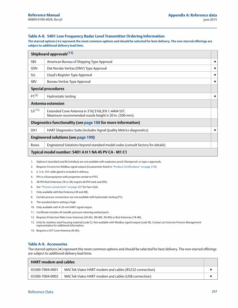
Reference Manual 00809-0100-4026, Rev JA
Appendix A: Reference dataJune 2015
Shipboard approvals(13)
SBS American Bureau of Shipping Type Approval ★
SDN Det Norske Veritas (DNV) Type Approval ★
SLL Lloyd's Register Type Approval ★
SBV Bureau Veritas Type Approval ★
Special procedures
P1(8) Hydrostatic testing ★
Antenna extension
S3(14) Extended Cone Antenna in 316/316L/EN 1.4404 SST. Maximum recommended nozzle height is 20 in. (500 mm).
Diagnostics functionality (see page 188 for more information)
DA1 HART Diagnostics Suite (includes Signal Quality Metrics diagnostics) ★
Engineered solutions (see page 199)
Rxxxx Engineered Solutions beyond standard model codes (consult factory for details)
Typical model number: 5401 A H 1 NA 4S PV CA - M1 C1
1. Options E (eurofast) and M (minifast) are not available with explosion-proof, flameproof, or type n approvals.
2. Requires FOUNDATION fieldbus signal output (Ui parameter listed in “Product Certifications” on page 219).
3. G ½ in. SST cable gland is included in delivery.
4. PFA is a fluoropolymer with properties similar to PTFE.
5. All-PFA Rod Antennas (1R or 2R) require all-PFA tank seal (PD).
6. See “Process connections” on page 207 for Face style.
7. Only available with Rod Antenna (3R and 4R).
8. Certain process connections are not available with hydrostatic testing (P1).
9. The standard alarm setting is high.
10. Only available with 4-20 mA HART signal output.
11. Certificate includes all metallic pressure retaining wetted parts.
12. Requires Protective Plate Cone Antennas (3H-8H, 3M-8M, 3N-8N) or Rod Antennas (1R-4R).
13. Only for stainless steel housing material (code S). Not available with Modbus signal output (code M). Contact an Emerson Process Management representative for additional information.
14. Requires a SST Cone Antenna (4S-8S).
Table A-9. AccessoriesThe starred options (★) represent the most common options and should be selected for best delivery. The non-starred offerings are subject to additional delivery lead time.
HART modem and cables
03300-7004-0001 MACTek Viator HART modem and cables (RS232 connection) ★
03300-7004-0002 MACTek Viator HART modem and cables (USB connection) ★
Table A-8. 5401 Low Frequency Radar Level Transmitter Ordering InformationThe starred options (★) represent the most common options and should be selected for best delivery. The non-starred offerings are subject to additional delivery lead time.
217Reference Data

Reference Manual00809-0100-4026, Rev JA
Appendix A: Reference dataJune 2015
218 Reference Data

Reference Manual 00809-0100-4026, Rev JA
Appendix B: Product certificationsJune 2015
Appendix B Product Certifications
Safety messages . . . . . . . . . . . . . . . . . . . . . . . . . . . . . . . . . . . . . . . . . . . . . . . . . . . . . . . . . . . . page 219European Directive information . . . . . . . . . . . . . . . . . . . . . . . . . . . . . . . . . . . . . . . . . . . . . . . page 221FCC and ICC . . . . . . . . . . . . . . . . . . . . . . . . . . . . . . . . . . . . . . . . . . . . . . . . . . . . . . . . . . . . . . . . page 221Safety Instrumented Systems (SIS) . . . . . . . . . . . . . . . . . . . . . . . . . . . . . . . . . . . . . . . . . . . . page 221Hazardous locations certifications . . . . . . . . . . . . . . . . . . . . . . . . . . . . . . . . . . . . . . . . . . . . page 222Approval drawings . . . . . . . . . . . . . . . . . . . . . . . . . . . . . . . . . . . . . . . . . . . . . . . . . . . . . . . . . . page 236
B.1 Safety messages
Procedures and instructions in this section may require special precautions to ensure the safety of the personnel performing the operations. Information that raises potential safety issues is
indicated by a warning symbol ( ). Refer to the following safety messages before performing an operation preceded by this symbol.
Explosions could result in death or serious injury.
Verify that the operating environment of the transmitter is consistent with the appropriate hazardous locations specifications.
To prevent ignition of flammable or combustible atmospheres, disconnect power before servicing.
Before connecting a Field Communicator in an explosive atmosphere, make sure the instruments in the loop are installed in accordance with intrinsically safe or non-incendive field wiring practices.
To avoid process leaks, only use O-rings designed to seal with the corresponding flange adapter.
Electrical shock can result in death or serious injury.
Avoid contact with the leads and terminals. High voltage that may be present on leads can cause electrical shock.
Make sure the main power to the Rosemount 5400 Series transmitter is off and the lines to any other external power source are disconnected or not powered while wiring the transmitter.
Antennas with non-conducting surfaces.
Antennas with non-conducting surfaces (e.g. rod antenna and process seal antenna) may generate an ignition-capable level of electrostatic charge under extreme conditions.Therefore, when the antenna is used in a potentially explosive atmosphere, appropriate measures must be taken to prevent electrostatic discharge.
219Product Certifications
Reference Manual00809-0100-4026, Rev JA
Appendix B: Product certificationsJune 2015
Failure to follow safe installation and service guidelines could result in death or serious injury.
Make sure the transmitter is installed by qualified personnel and in accordance with applicable code of practice.
Use the equipment only as specified in this manual. Failure to do so may impair the protection provided by the equipment.
Do not perform any services other than those contained in this manual unless you are qualified.
Any substitution of non-recognized spare parts may jeopardize safety.
Unauthorized changes to the product are strictly prohibited as they may unintentionally and unpredictably alter performance and jeopardize safety. Unauthorized changes that interfere with the integrity of the welds or flanges, such as making additional perforations, compromise product integrity and safety. Equipment ratings and certifications are no longer valid on any products that have been damaged or modified without the prior written permission of Emerson Process Management. Any continued use of product that has been damaged or modified without prior written authorization is at the customer's sole risk and expense.
220 Product Certifications

Reference Manual 00809-0100-4026, Rev JA
Appendix B: Product certificationsJune 2015
B.2 European Directive information
The EC declaration of conformity for all applicable European directives for this product can be found on the Rosemount website at www.rosemount.com.
A hard copy may be obtained by contacting our local sales representative.
B.3 FCC and ICC
This device complies with Part 15 of the FCC Rules and with Industry Canada license-exempt RSS standard(s). Operation is subject to the following two conditions: (1) This device may not cause interference, and (2) this device must accept any interference received, including interference that may cause undesired operation.
Le présent appareil est conforme aux CNR d'Industrie Canada applicables aux appareils radio exempts de licence. L'exploitation est autorisée aux deux conditions suivantes: (1) l'appareil ne doit pas produire de brouillage, et (2) l'utilisateur de l'appareil doit accepter tout brouillage radioélectrique subi, même si le brouillage est susceptible d'en compromettre le fonctionnement.
B.4 Safety Instrumented Systems (SIS)(1)
The Rosemount 5400 Series has been evaluated by a third party, the SP (Technical Research Institute of Sweden), against hardware requirements according to IEC 61508. With a FMEDA (Failure Modes, Effects and Diagnostics Analysis) report with a Safe Failure Fraction (SFF) above 80%, 5400 is suitable in SIS according to the Prior Use methodology. For more information, go to: http://www.rosemount.com/safety. To order the certificate of FMEDA data, use option code QS.
Changes or modifications to this equipment not expressly approved by Rosemount Inc. may void the FCC authorization to operate this equipment.
Les changements ou les modifications apportés à l'équipement qui n'est pas expressément approuvé par Rosemount Inc pourraient annuler l'autorité de l'utilisateur à utiliser cet équipement.
1. Not available for solids applications.
221Product Certifications
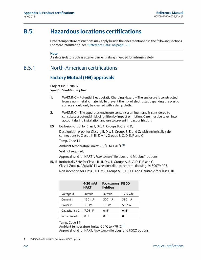
Reference Manual00809-0100-4026, Rev JA
Appendix B: Product certificationsJune 2015
B.5 Hazardous locations certifications
Other temperature restrictions may apply beside the ones mentioned in the following sections. For more information, see “Reference Data” on page 179.
NoteA safety isolator such as a zener barrier is always needed for intrinsic safety.
B.5.1 North-American certifications
Factory Mutual (FM) approvals
Project ID: 3020497Specific Conditions of Use:
1. WARNING – Potential Electrostatic Charging Hazard – The enclosure is constructed from a non-metallic material. To prevent the risk of electrostatic sparking the plastic surface should only be cleaned with a damp cloth.
2. WARNING – The apparatus enclosure contains aluminum and is considered to constitute a potential risk of ignition by impact or friction. Care must be taken into account during installation and use to prevent impact or friction.
E5 Explosion-proof for Class I, Div. 1, Groups B, C, and D;
Dust ignition proof for Class II/III, Div. 1, Groups E, F, and G; with intrinsically safe connections to Class I, II, III, Div. 1, Groups B, C, D, E, F, and G.
Temp. Code T4
Ambient temperature limits: -50 °C to +70 °C(1).
Seal not required.
Approval valid for HART®, FOUNDATION™ fieldbus, and Modbus® options.
I5, IE Intrinsically Safe for Class I, II, III, Div. 1, Groups A, B, C, D, E, F, and G,Class I, Zone 0, AEx ia IIC T4 when installed per control drawing: 9150079-905.
Non-incendive for Class I, II, Div.2, Groups A, B, C, D, F, and G suitable for Class II, III.
Temp. Code T4Ambient temperature limits: -50 °C to +70 °C(1)
Approval valid for HART, FOUNDATION fieldbus, and FISCO options.
1. +60 °C with FOUNDATION fieldbus or FISCO option.
4-20 mA/HART
FOUNDATION fieldbus
FISCO
Voltage Ui 30 Vdc 30 Vdc 17.5 Vdc
Current Ii 130 mA 300 mA 380 mA
Power Pi 1.0 W 1.3 W 5.32 W
Capacitance Ci 7.26 nF 0 nF 0 nF
Inductance Li 0 H 0 H 0 H
222 Product Certifications
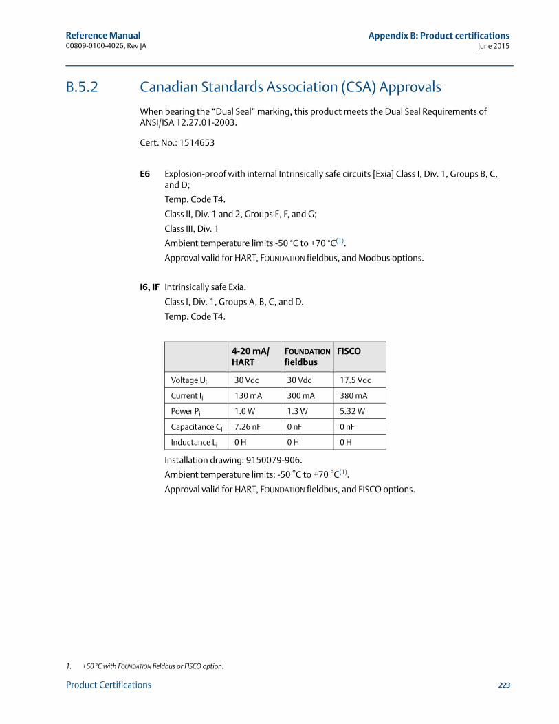
Reference Manual 00809-0100-4026, Rev JA
Appendix B: Product certificationsJune 2015
B.5.2 Canadian Standards Association (CSA) Approvals
When bearing the “Dual Seal” marking, this product meets the Dual Seal Requirements of ANSI/ISA 12.27.01-2003.
Cert. No.: 1514653
E6 Explosion-proof with internal Intrinsically safe circuits [Exia] Class I, Div. 1, Groups B, C, and D;
Temp. Code T4.
Class II, Div. 1 and 2, Groups E, F, and G;
Class III, Div. 1
Ambient temperature limits -50 °C to +70 °C(1).
Approval valid for HART, FOUNDATION fieldbus, and Modbus options.
I6, IF Intrinsically safe Exia.
Class I, Div. 1, Groups A, B, C, and D.
Temp. Code T4.
Installation drawing: 9150079-906.
Ambient temperature limits: -50 °C to +70 °C(1).
Approval valid for HART, FOUNDATION fieldbus, and FISCO options.
1. +60 °C with FOUNDATION fieldbus or FISCO option.
4-20 mA/HART
FOUNDATION fieldbus
FISCO
Voltage Ui 30 Vdc 30 Vdc 17.5 Vdc
Current Ii 130 mA 300 mA 380 mA
Power Pi 1.0 W 1.3 W 5.32 W
Capacitance Ci 7.26 nF 0 nF 0 nF
Inductance Li 0 H 0 H 0 H
223Product Certifications
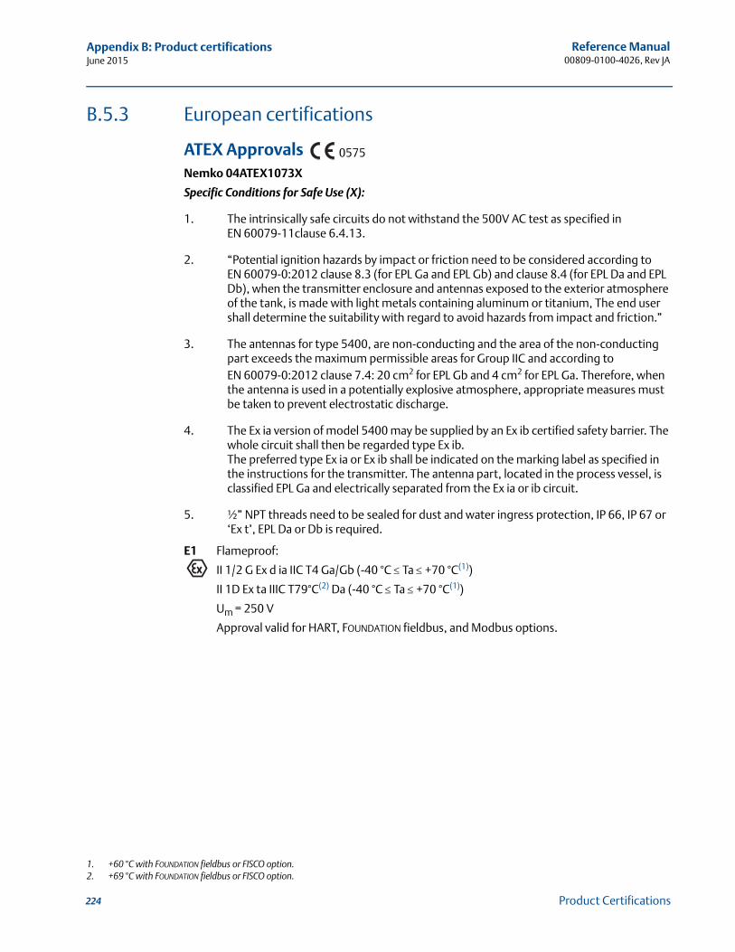
Reference Manual00809-0100-4026, Rev JA
Appendix B: Product certificationsJune 2015
B.5.3 European certifications
ATEX ApprovalsNemko 04ATEX1073X
Specific Conditions for Safe Use (X):
1. The intrinsically safe circuits do not withstand the 500V AC test as specified in EN 60079-11clause 6.4.13.
2. “Potential ignition hazards by impact or friction need to be considered according to EN 60079-0:2012 clause 8.3 (for EPL Ga and EPL Gb) and clause 8.4 (for EPL Da and EPL Db), when the transmitter enclosure and antennas exposed to the exterior atmosphere of the tank, is made with light metals containing aluminum or titanium, The end user shall determine the suitability with regard to avoid hazards from impact and friction.”
3. The antennas for type 5400, are non-conducting and the area of the non-conducting part exceeds the maximum permissible areas for Group IIC and according to EN 60079-0:2012 clause 7.4: 20 cm2 for EPL Gb and 4 cm2 for EPL Ga. Therefore, when the antenna is used in a potentially explosive atmosphere, appropriate measures must be taken to prevent electrostatic discharge.
4. The Ex ia version of model 5400 may be supplied by an Ex ib certified safety barrier. The whole circuit shall then be regarded type Ex ib. The preferred type Ex ia or Ex ib shall be indicated on the marking label as specified in the instructions for the transmitter. The antenna part, located in the process vessel, is classified EPL Ga and electrically separated from the Ex ia or ib circuit.
5. ½” NPT threads need to be sealed for dust and water ingress protection, IP 66, IP 67 or ‘Ex t’, EPL Da or Db is required.
E1 Flameproof:
II 1/2 G Ex d ia IIC T4 Ga/Gb (-40 °C Ta +70 °C(1))
II 1D Ex ta IIIC T79°C(2) Da (-40 °C Ta +70 °C(1))
Um = 250 V
Approval valid for HART, FOUNDATION fieldbus, and Modbus options.
1. +60 °C with FOUNDATION fieldbus or FISCO option.2. +69 °C with FOUNDATION fieldbus or FISCO option.
0575
224 Product Certifications
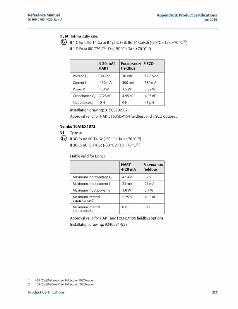
Reference Manual 00809-0100-4026, Rev JA
Appendix B: Product certificationsJune 2015
I1, IA Intrinsically safe:
II 1 G Ex ia IIC T4 Ga or II 1/2 G Ex ib IIC T4 Ga/Gb (-50 °C Ta +70 °C(1))
II 1 D Ex ta IIIC T79°C(2) Da (-50 °C Ta +70 °C(1))
Installation drawing: 9150079-907.
Approval valid for HART, FOUNDATION fieldbus, and FISCO options.
Nemko 10ATEX1072
N1 Type n:
II 3G Ex nA IIC T4 Gc (-50 °C Ta +70 °C(1))
II 3G Ex nL IIC T4 Gc (-50 °C Ta +70 °C(1))
(Table valid for Ex nL)
Approval valid for HART and FOUNDATION fieldbus options.
Installation drawing: 9240031-958
1. +60 °C with FOUNDATION fieldbus or FISCO option.2. +69 °C with FOUNDATION fieldbus or FISCO option.
4-20 mA/HART
FOUNDATION fieldbus
FISCO
Voltage Ui 30 Vdc 30 Vdc 17.5 Vdc
Current Ii 130 mA 300 mA 380 mA
Power Pi 1.0 W 1.5 W 5.32 W
Capacitance Ci 7.26 nF 4.95 nF 4.95 nF
Inductance Li 0 H 0 H <1 μH
HART 4-20 mA
FOUNDATION fieldbus
Maximum input voltage Ui 42.4 V 32 V
Maximum input current Ii 23 mA 21 mA
Maximum input power Pi 1.0 W 0.7 W
Maximum internal capacitance Ci
7.25 nF 4.95 nF
Maximum internal inductance Li
0 H 0 H
225Product Certifications
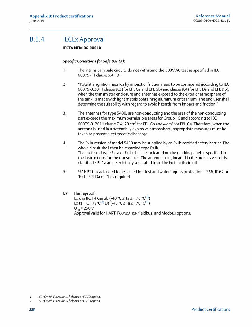
Reference Manual00809-0100-4026, Rev JA
Appendix B: Product certificationsJune 2015
B.5.4 IECEx ApprovalIECEx NEM 06.0001X
Specific Conditions for Safe Use (X):
1. The intrinsically safe circuits do not withstand the 500V AC test as specified in IEC 60079-11 clause 6.4.13.
2. “Potential ignition hazards by impact or friction need to be considered according to IEC 60079-0:2011 clause 8.3 (for EPL Ga and EPL Gb) and clause 8.4 (for EPL Da and EPL Db), when the transmitter enclosure and antennas exposed to the exterior atmosphere of the tank, is made with light metals containing aluminum or titanium, The end user shall determine the suitability with regard to avoid hazards from impact and friction.”
3. The antennas for type 5400, are non-conducting and the area of the non-conducting part exceeds the maximum permissible areas for Group IIC and according to IEC 60079-0 .2011 clause 7.4: 20 cm² for EPL Gb and 4 cm² for EPL Ga. Therefore, when the antenna is used in a potentially explosive atmosphere, appropriate measures must be taken to prevent electrostatic discharge.
4. The Ex ia version of model 5400 may be supplied by an Ex ib certified safety barrier. The whole circuit shall then be regarded type Ex ib. The preferred type Ex ia or Ex ib shall be indicated on the marking label as specified in the instructions for the transmitter. The antenna part, located in the process vessel, is classified EPL Ga and electrically separated from the Ex ia or ib circuit.
5. ½” NPT threads need to be sealed for dust and water ingress protection, IP 66, IP 67 or ‘Ex t’, EPL Da or Db is required.
E7 Flameproof:Ex d ia IIC T4 Ga/Gb (-40 °C Ta +70 °C(1))Ex ta IIIC T79°C(2) Da (-40 °C Ta +70 °C(1))Um = 250 VApproval valid for HART, FOUNDATION fieldbus, and Modbus options.
1. +60 °C with FOUNDATION fieldbus or FISCO option.2. +69 °C with FOUNDATION fieldbus or FISCO option.
226 Product Certifications
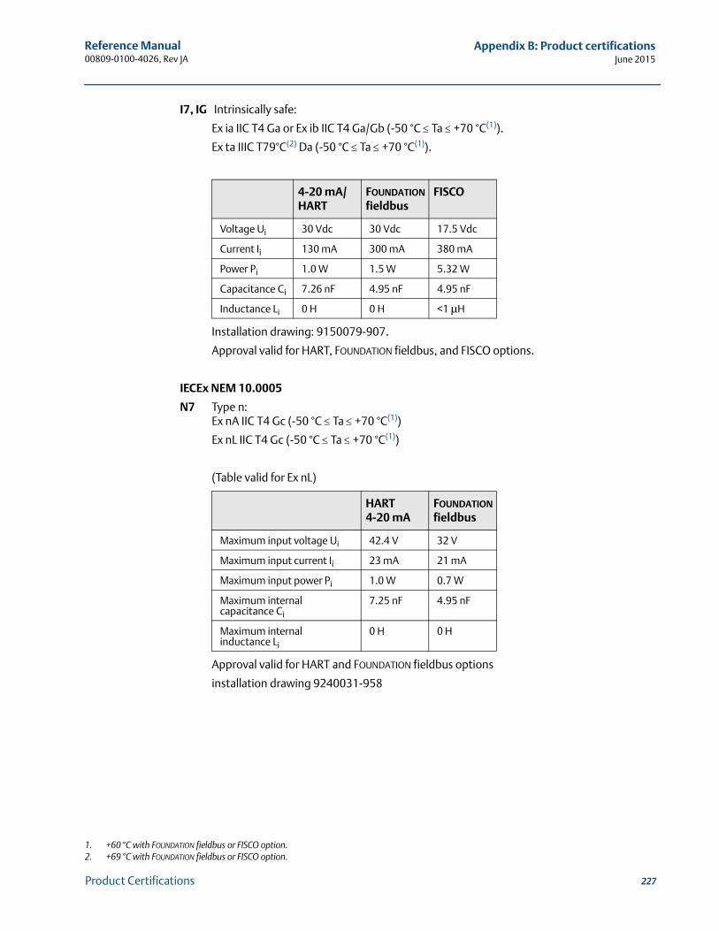
Reference Manual 00809-0100-4026, Rev JA
Appendix B: Product certificationsJune 2015
I7, IG Intrinsically safe:
Ex ia IIC T4 Ga or Ex ib IIC T4 Ga/Gb (-50 °C Ta +70 °C(1)).
Ex ta IIIC T79°C(2) Da (-50 °C Ta +70 °C(1)).
Installation drawing: 9150079-907.
Approval valid for HART, FOUNDATION fieldbus, and FISCO options.
IECEx NEM 10.0005
N7 Type n:Ex nA IIC T4 Gc (-50 °C Ta +70 °C(1))
Ex nL IIC T4 Gc (-50 °C Ta +70 °C(1))
(Table valid for Ex nL)
Approval valid for HART and FOUNDATION fieldbus options
installation drawing 9240031-958
1. +60 °C with FOUNDATION fieldbus or FISCO option.2. +69 °C with FOUNDATION fieldbus or FISCO option.
4-20 mA/HART
FOUNDATION fieldbus
FISCO
Voltage Ui 30 Vdc 30 Vdc 17.5 Vdc
Current Ii 130 mA 300 mA 380 mA
Power Pi 1.0 W 1.5 W 5.32 W
Capacitance Ci 7.26 nF 4.95 nF 4.95 nF
Inductance Li 0 H 0 H <1 μH
HART 4-20 mA
FOUNDATION fieldbus
Maximum input voltage Ui 42.4 V 32 V
Maximum input current Ii 23 mA 21 mA
Maximum input power Pi 1.0 W 0.7 W
Maximum internal capacitance Ci
7.25 nF 4.95 nF
Maximum internal inductance Li
0 H 0 H
227Product Certifications
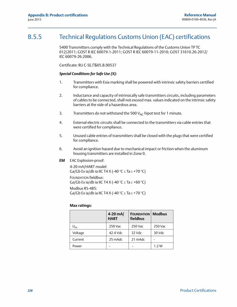
Reference Manual00809-0100-4026, Rev JA
Appendix B: Product certificationsJune 2015
B.5.5 Technical Regulations Customs Union (EAC) certifications
5400 Transmitters comply with the Technical Regulations of the Customs Union TP TC 012/2011; GOST R IEC 60079-1-2011; GOST R IEC 60079-11-2010; GOST 31610.26-2012/IEC 60079-26:2006.
Certificate: RU C-SE.ГБ05.B.00537
Special Conditions for Safe Use (X):
1. Transmitters with Exia marking shall be powered with intrinsic safety barriers certified for compliance.
2. Inductance and capacity of intrinsically safe transmitters circuits, including parameters of cables to be connected, shall not exceed max. values indicated on the intrinsic safety barriers at the side of a hazardous area.
3. Transmitters do not withstand the 500 VAC hipot test for 1 minute.
4. External electric circuits shall be connected to the transmitters via cable entries that were certified for compliance.
5. Unused cable entries of transmitters shall be closed with the plugs that were certified for compliance.
6. Avoid an ignition hazard due to mechanical impact or friction when the aluminum housing transmitters are installed in Zone 0.
EM EAC Explosion-proof:
4-20 mA/HART model:Ga/Gb Ex ia/db ia IIC T4 X (-40 °C Ta +70 °C)
FOUNDATION fieldbus:Ga/Gb Ex ia/db ia IIC T4 X (-40 °C Ta +60 °C)
Modbus RS-485:Ga/Gb Ex ia/db ia IIC T4 X (-40 °C Ta +70 °C)
Max ratings:
4-20 mA/HART
FOUNDATION fieldbus
Modbus
Um 250 Vac 250 Vac 250 Vac
Voltage 42.4 Vdc 32 Vdc 30 Vdc
Current 25 mAdc 21 mAdc -
Power - - 1.2 W
228 Product Certifications
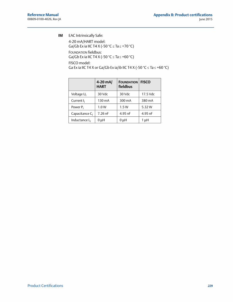
Reference Manual 00809-0100-4026, Rev JA
Appendix B: Product certificationsJune 2015
IM EAC Intrinsically Safe:
4-20 mA/HART model:Ga/Gb Ex ia IIC T4 X (-50 °C Ta +70 °C)
FOUNDATION fieldbus:Ga/Gb Ex ia IIC T4 X (-50 °C Ta +60 °C)
FISCO model:Ga Ex ia IIC T4 X or Ga/Gb Ex ia/ib IIC T4 X (-50 °C Ta +60 °C)
4-20 mA/HART
FOUNDATION fieldbus
FISCO
Voltage Ui 30 Vdc 30 Vdc 17.5 Vdc
Current Ii 130 mA 300 mA 380 mA
Power Pi 1.0 W 1.5 W 5.32 W
Capacitance Ci 7.26 nF 4.95 nF 4.95 nF
Inductance Li 0 μH 0 μH 1 μH
229Product Certifications
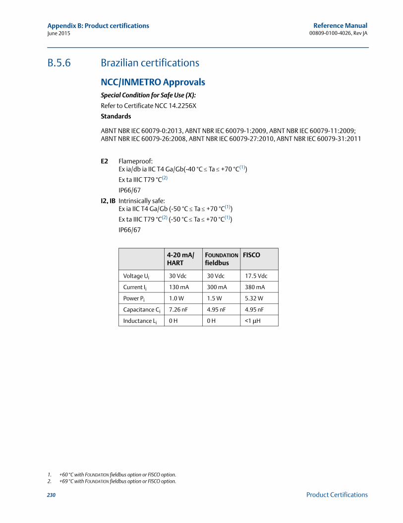
Reference Manual00809-0100-4026, Rev JA
Appendix B: Product certificationsJune 2015
B.5.6 Brazilian certifications
NCC/INMETRO ApprovalsSpecial Condition for Safe Use (X):
Refer to Certificate NCC 14.2256X
Standards
ABNT NBR IEC 60079-0:2013, ABNT NBR IEC 60079-1:2009, ABNT NBR IEC 60079-11:2009; ABNT NBR IEC 60079-26:2008, ABNT NBR IEC 60079-27:2010, ABNT NBR IEC 60079-31:2011
E2 Flameproof:Ex ia/db ia IIC T4 Ga/Gb(-40 °C Ta +70 °C(1))
Ex ta IIIC T79 °C(2)
IP66/67
I2, IB Intrinsically safe:Ex ia IIC T4 Ga/Gb (-50 °C Ta +70 °C(1))
Ex ta IIIC T79 °C(2) (-50 °C Ta +70 °C(1))
IP66/67
1. +60 °C with FOUNDATION fieldbus option or FISCO option.2. +69 °C with FOUNDATION fieldbus option or FISCO option.
4-20 mA/HART
FOUNDATION fieldbus
FISCO
Voltage Ui 30 Vdc 30 Vdc 17.5 Vdc
Current Ii 130 mA 300 mA 380 mA
Power Pi 1.0 W 1.5 W 5.32 W
Capacitance Ci 7.26 nF 4.95 nF 4.95 nF
Inductance Li 0 H 0 H <1 μH
230 Product Certifications
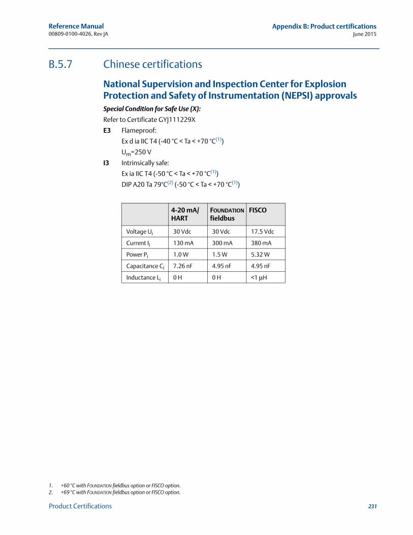
Reference Manual 00809-0100-4026, Rev JA
Appendix B: Product certificationsJune 2015
B.5.7 Chinese certifications
National Supervision and Inspection Center for Explosion Protection and Safety of Instrumentation (NEPSI) approvalsSpecial Condition for Safe Use (X):
Refer to Certificate GYJ111229X
E3 Flameproof:
Ex d ia IIC T4 (-40 °C < Ta < +70 °C(1))
Um=250 V
I3 Intrinsically safe:
Ex ia IIC T4 (-50 °C < Ta < +70 °C(1))
DIP A20 Ta 79°C(2) (-50 °C < Ta < +70 °C(1))
1. +60 °C with FOUNDATION fieldbus option or FISCO option.2. +69 °C with FOUNDATION fieldbus option or FISCO option.
4-20 mA/HART
FOUNDATION fieldbus
FISCO
Voltage Ui 30 Vdc 30 Vdc 17.5 Vdc
Current Ii 130 mA 300 mA 380 mA
Power Pi 1.0 W 1.5 W 5.32 W
Capacitance Ci 7.26 nF 4.95 nF 4.95 nF
Inductance Li 0 H 0 H <1 μH
231Product Certifications

Reference Manual00809-0100-4026, Rev JA
Appendix B: Product certificationsJune 2015
B.5.8 Japanese certifications
Technology Institution of Industrial Safety (TIIS) ApprovalSpecial Condition for Safe Use (X):
Refer to certificate TC20109-TC20111 (4-20 mA HART) and TC20244-TC20246 FOUNDATION fieldbus)
E4(1) Flameproof: 4-20 mA HART model:Transmitter: Ex d [ia] IIC T4x-20 ~ +60 °CDC 20 - 42.4 VUm = 250 VUo = 22.2 VIo = 177 mAPo = 0.985 WAntennas: Ex ia IIC T4X
FOUNDATION fieldbus model:Transmitter: Ex d [ia] IIC T4x-20 ~ +60 °CDC 16 - 32 VUm = 250 VUo = 22.2 VIo = 177.5 mAPo = 0.985 WAntennas: Ex ia IIC T4XInstallation drawing: 05400-00375.Approval valid for HART and FOUNDATION fieldbus options.
1. Not available for solids applications.
232 Product Certifications
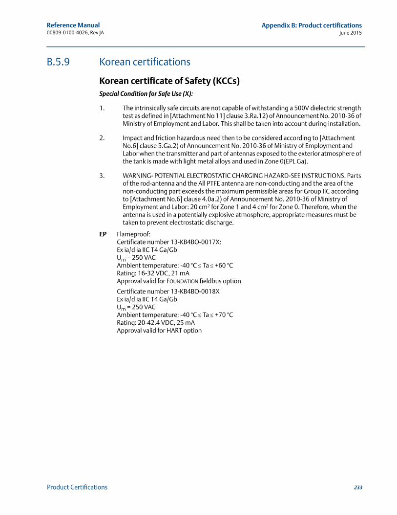
Reference Manual 00809-0100-4026, Rev JA
Appendix B: Product certificationsJune 2015
B.5.9 Korean certifications
Korean certificate of Safety (KCCs)Special Condition for Safe Use (X):
1. The intrinsically safe circuits are not capable of withstanding a 500V dielectric strength test as defined in [Attachment No 11] clause 3.Ra.12) of Announcement No. 2010-36 of Ministry of Employment and Labor. This shall be taken into account during installation.
2. Impact and friction hazardous need then to be considered according to [Attachment No.6] clause 5.Ga.2) of Announcement No. 2010-36 of Ministry of Employment and Labor when the transmitter and part of antennas exposed to the exterior atmosphere of the tank is made with light metal alloys and used in Zone 0(EPL Ga).
3. WARNING- POTENTIAL ELECTROSTATIC CHARGING HAZARD-SEE INSTRUCTIONS. Parts of the rod-antenna and the All PTFE antenna are non-conducting and the area of the non-conducting part exceeds the maximum permissible areas for Group IIC according to [Attachment No.6] clause 4.0a.2) of Announcement No. 2010-36 of Ministry of Employment and Labor: 20 cm² for Zone 1 and 4 cm² for Zone 0. Therefore, when the antenna is used in a potentially explosive atmosphere, appropriate measures must be taken to prevent electrostatic discharge.
EP Flameproof:Certificate number 13-KB4BO-0017X:Ex ia/d ia IIC T4 Ga/GbUm = 250 VACAmbient temperature: -40 °C Ta +60 °CRating: 16-32 VDC, 21 mAApproval valid for FOUNDATION fieldbus option
Certificate number 13-KB4BO-0018XEx ia/d ia IIC T4 Ga/GbUm = 250 VACAmbient temperature: -40 °C Ta +70 °CRating: 20-42.4 VDC, 25 mAApproval valid for HART option
233Product Certifications
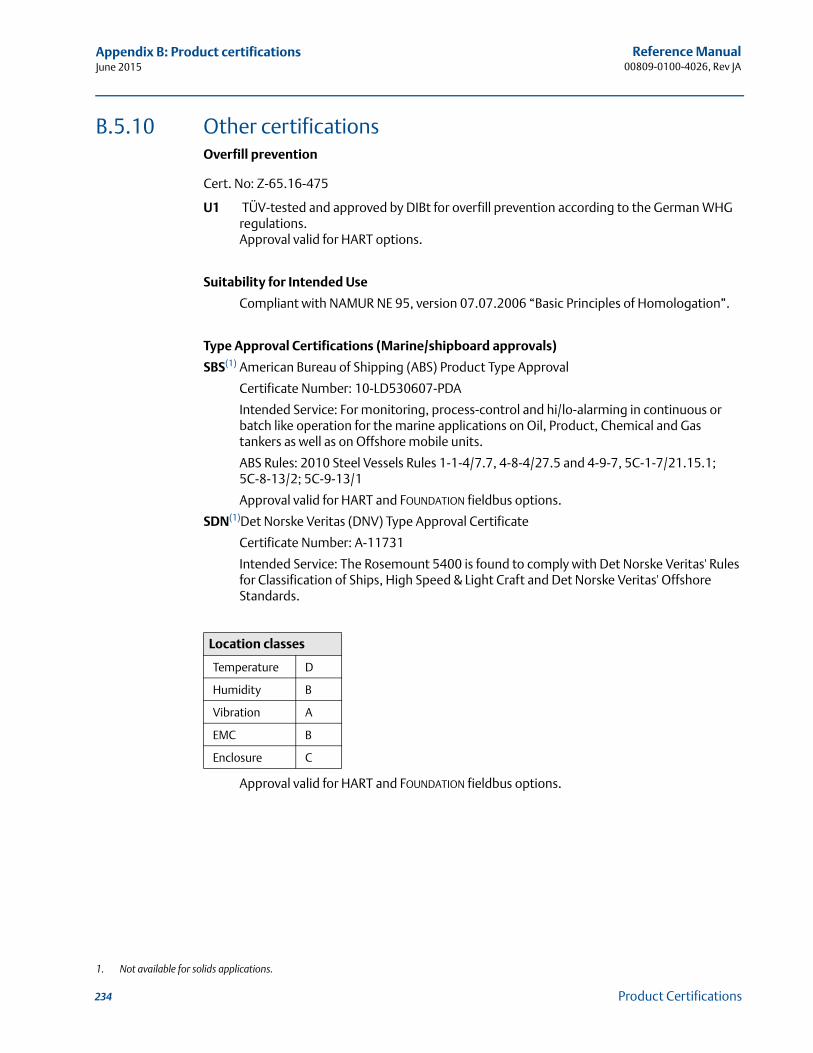
Reference Manual00809-0100-4026, Rev JA
Appendix B: Product certificationsJune 2015
B.5.10 Other certificationsOverfill prevention
Cert. No: Z-65.16-475
U1 TÜV-tested and approved by DIBt for overfill prevention according to the German WHG regulations.Approval valid for HART options.
Suitability for Intended Use
Compliant with NAMUR NE 95, version 07.07.2006 “Basic Principles of Homologation”.
Type Approval Certifications (Marine/shipboard approvals)
SBS(1) American Bureau of Shipping (ABS) Product Type Approval
Certificate Number: 10-LD530607-PDA
Intended Service: For monitoring, process-control and hi/lo-alarming in continuous or batch like operation for the marine applications on Oil, Product, Chemical and Gas tankers as well as on Offshore mobile units.
ABS Rules: 2010 Steel Vessels Rules 1-1-4/7.7, 4-8-4/27.5 and 4-9-7, 5C-1-7/21.15.1; 5C-8-13/2; 5C-9-13/1
Approval valid for HART and FOUNDATION fieldbus options.
SDN(1)Det Norske Veritas (DNV) Type Approval Certificate
Certificate Number: A-11731
Intended Service: The Rosemount 5400 is found to comply with Det Norske Veritas' Rules for Classification of Ships, High Speed & Light Craft and Det Norske Veritas' Offshore Standards.
Approval valid for HART and FOUNDATION fieldbus options.
1. Not available for solids applications.
Location classes
Temperature D
Humidity B
Vibration A
EMC B
Enclosure C
234 Product Certifications

Reference Manual 00809-0100-4026, Rev JA
Appendix B: Product certificationsJune 2015
SLL(1) Lloyd's Register Type Approval Certificate
Certificate Number: 09/00034
Application: For use in environmental categories ENV1, ENV2, ENV3 and ENV5 as defined in Lloyd's Register Test Specification No. 1: 2002.
Approval valid for HART and FOUNDATION fieldbus options.
SBV(1) Bureau Veritas Type Approval Certificate
Certificate Number: 22379/A0 BV
Requirements: BUREAU VERITAS Rules for the Classification of Steel Ships
Application: Approval valid for ships intended to be granted with the following additional class notations: AUT-UMS, AUT-CCS, AUT-PORT and AUT-IMS.
Approval valid for HART and FOUNDATION fieldbus options.
B.5.11 Canadian Registration Number (CRN)Cert No: 0F06878.2
The product design has been accepted and registered for use in Canada.
1. Not available for solids applications.
235Product Certifications
Reference Manual00809-0100-4026, Rev JA
Appendix B: Product certificationsJune 2015
B.6 Approval drawings
This section contains a FM Approvals system control drawing and Canadian Standards Association and IECEx/ATEX/TIIS installation drawings. You must follow the installation guidelines presented in order to maintain certified ratings for installed transmitters.
This section contains the following drawings:
Rosemount drawing 9150 079-905:System control drawing for hazardous location installation of intrinsically safe FM approved apparatus.
Rosemount drawing 9150 079-906:System control drawing for hazardous location installation of CSA approved apparatus.
Rosemount drawing 9150 079-907:Installation drawing for hazardous location installation of ATEX and IECEx approved apparatus.
Rosemount drawing 9240031-958:Installation drawing Ex n Rosemount 5400 Series
TIIS drawing TIIS-R-IS 05400-00375:Installation drawing for hazardous location installation of TIIS approved apparatus.
236 Product Certifications
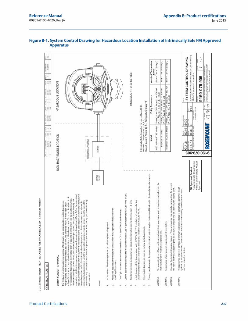
237
Reference Manual 00809-0100-4026, Rev JA
Appendix B: Product certificationsJune 2015
Product Certifications
Figure B-1. System Control Drawing for Hazardous Location Installation of Intrinsically Safe FM Approved Apparatus
FM A
ppro
ved
Prod
uct
No
revi
sion
s to
this
dra
win
gw
ithou
t prio
r Fac
tory
Mut
ual
App
rova
l.
SME-
3446
0346
1
ISS
UE
CH
. OR
DE
R N
oW
EEK
ISS
UE
CH
. OR
DE
R N
oW
EEK
ISS
UE
CH
. OR
DE
R N
oW
EEK
ISS
UE
CH
. OR
DE
R N
oW
EEK
A3O
RIG
INA
L SI
ZE
GU
-LN
0346
5400
GU
-PO
6P
DF
9150 079-905
9150
079
-905
0346
SYST
EM C
ON
TRO
L D
RA
WIN
Gfo
r haz
ardo
us lo
catio
n in
stal
latio
n of
Intri
nsic
ally
Saf
e FM
app
rove
d ap
para
tus
71
/ 1
ISSU
ED B
Y
APPR
OVE
D B
Y
WEE
K
WEE
K
PR
OD
UC
T C
OD
E
DO
C. T
YPE
FILE
TITL
E
DW
G N
O.
ISS
UE
SHEE
T
SCAL
E
1:1
1 ST
AN
GLE
FIN
ISH
, UN
LESS
OTH
ERW
ISE
STAT
ED:
ALL
DIM
ENSI
ON
S AR
E IN
MIL
LIM
ETR
ES.
The
cop
yrig
ht/o
wne
rshi
p of
this
doc
umen
t is
and
will
rem
ain
ours
.T
he d
ocum
ent m
ust n
ot b
e us
ed w
ithou
t our
aut
horiz
atio
n or
bro
ught
to t
he k
now
ledg
e of
a th
ird p
arty
. Con
trave
ntio
n w
ill be
pro
secu
ted.
Ro
sem
ou
nt
Tan
k R
ad
ar
AB
, S
wed
en
ASSO
CIAT
ED A
PPAR
ATU
S
BARR
IER
POW
ERSU
PPLY
HAZ
ARD
OU
S LO
CATI
ON
NO
N-H
AZAR
DO
US
LOCA
TIO
NEN
TITY
CO
NC
EPT
APP
RO
VAL
The
Enti
ty c
on
cep
t allo
ws
inte
rco
nn
ecti
on
of i
ntri
nsi
cally
saf
e ap
par
atu
s to
ass
oci
ated
ap
par
atu
s n
ot s
pec
ifica
lly e
xam
ined
in c
om
bin
atio
n a
s a
syst
em. T
he
app
rove
d v
alu
es o
f max
. op
en c
ircu
it
volt
age
(Vo
c o
r Vt)
an
d m
ax. s
ho
rt c
ircu
it c
urr
ent (
Isc
or I
t) a
nd
max
. pow
er (
Voc
x Is
c /
4) o
r (V
t x It
/ 4
), fo
r th
e as
soci
ated
ap
par
atu
s m
ust
be
less
than
or e
qu
al to
the
max
imu
m s
afe
inp
ut v
olt
age
(Vm
ax),
max
imu
m s
afe
inp
ut c
urr
ent (
Imax
), an
d m
axim
um
saf
e in
pu
t pow
er (P
max
) of t
he
intr
insi
cally
saf
e ap
par
atu
s. In
ad
dit
ion
, th
e ap
pro
ved
max
. allo
wab
le c
on
nec
ted
cap
acit
ance
(Ca
or C
o) o
f th
e as
soci
ated
ap
par
atu
s m
ust
be
gre
ater
than
the
sum
of t
he
inte
rco
nn
ecti
ng
cab
le c
apac
itan
ce a
nd
the
un
pro
tect
ed
inte
rnal
cap
acit
ance
(Ci)
of t
he
intr
insi
cally
saf
e ap
par
atu
s, an
d th
e th
e ap
pro
ved
max
. allo
wab
le
con
nec
ted
ind
uct
ance
(La
or L
o) o
f th
e as
soci
ated
ap
par
atu
s m
ust
be
gre
ater
than
the
sum
of t
he
inte
rco
nn
ecti
ng
cab
le in
du
ctan
ce a
nd
the
un
pro
tect
ed in
tern
al in
du
ctan
ce (L
i) o
f th
e in
trin
sica
llysa
fe a
pp
arat
us.
No
tes:
1.
No
revi
sio
n to
this
dra
win
g w
ith
ou
t pri
or F
acto
ry M
utu
al a
pp
rova
l.
2.
Ass
oci
ated
ap
par
atu
s m
anu
fact
ure
r's in
stal
lati
on
dra
win
g m
ust
be
follo
wed
wh
en
in
stal
ling
this
pro
du
ct.
3.
Du
st-T
igh
t sea
l mu
st b
e u
sed
wh
en in
stal
led
in C
lass
II a
nd
Cla
ss II
I env
iro
nm
ents
.
4.
Co
ntr
ol e
qu
ipm
ent c
on
nec
ted
to th
e b
arri
er m
ust
no
t use
or g
ener
ate
mo
re th
an 2
50 V
rms
or V
dc.
5.
Resi
stan
ce b
etw
een
Intr
insi
cally
Saf
e G
rou
nd
an
d E
arth
Gro
un
d m
ust
be
less
than
1.0
oh
m.
6.
Inst
alla
tio
ns
sho
uld
be
in a
cco
rdan
ce w
ith
AN
SI/I
SA-R
P12.
6 "I
nst
alla
tio
n o
f In
trin
sica
lly S
afe
Sy
stem
s fo
r Haz
ard
ou
s Lo
cati
on
s" a
nd
the
Nat
ion
al E
lect
ric
Co
de
(AN
SI/N
FPA
70)
.
7.
The
asso
ciat
ed a
pp
arat
us
mu
st b
e Fa
cto
ry M
utu
al A
pp
rove
d.
8.
Co
nn
ect s
up
ply
wir
es to
the
app
rop
riat
e te
rmin
als
as in
dic
ated
on
the
term
inal
blo
ck a
nd
in th
e in
stal
lati
on
do
cum
ents
.
RO
SEM
OU
NT
5400
SER
IES
Intri
nsic
ally
Safe
Appa
ratu
sfo
ruse
inC
lass
I,II,I
II,D
ivis
ion
1,G
roup
sA,
B,C
,D,E
,F,G
,C
lass
I,Zo
ne0,
AEx
iaIIC
T4,T
empe
ratu
reC
lass
T4:
Mod
elEn
tity
Para
met
ers
Am
bien
tTem
pera
ture
Lim
its4-
20m
A/H
ART
ISM
odel
Vmax
(Ui)
<=30
V,Im
ax(Ii
)<=
130
mA
Pi<
=1W
,Ci=
7.2
6 nF
,Li=
0 u
H
-50
<=Ta
<=70
deg
C
Fiel
dbus
ISM
odel
Vmax
(Ui)
<=30
V,Im
ax(Ii
)<=
300
mA
Pi<=
1.3W
,Ci=
0,Li
=0
uH-5
0<=
Ta<=
60de
gC
Fiel
dbus
FIS
CO
ISM
odel
Vmax
(Ui)
<=17
.5V
, Im
ax(Ii
) <=
380
mA
Pi<=
5.32
W,C
i=0,
Li=
0uH
-50
<=Ta
<=60
deg
C
2SM
E-51
3405
263
SME-
5513
0644
4SM
E-58
7907
51 5
SME-
7120
1144
SME-
7473
1242
7SM
E-76
5514
09
WA
RNIN
G :
To
pre
ven
t ig
nit
ion
of f
lam
mab
le o
r co
mb
ust
ible
atm
osp
her
es, r
ead
, u
nd
erst
and
an
d a
dh
ere
to t
he
man
ufa
ctu
rer's
live
mai
nte
nan
ce p
roce
du
res.
WA
RNIN
G:
Sub
stit
uti
on
of c
om
po
nen
ts m
ay im
pai
r In
trin
sic
Safe
ty.
WA
RNIN
G:
Pote
nti
al E
lect
rost
atic
Ch
arg
ing
Haz
ard
– T
he
encl
osu
re is
a n
on
-met
allic
co
nst
ruct
ion
. To
pre
ven
t
th
e ri
sk o
f ele
ctro
stat
ic s
par
kin
g t
he
pla
stic
su
rfac
e sh
ou
ld o
nly
be
clea
ned
wit
h a
dam
p c
loth
.
WA
RNIN
G:
The
app
arat
us
encl
osu
re c
on
tain
s al
um
inu
m a
nd
is c
on
sid
ered
to c
on
stit
ute
a p
ote
nti
al ri
sk o
f
ig
nit
ion
by
imp
act
or f
rict
ion
. Car
e m
ust
be
take
n in
to a
cco
un
t d
uri
ng
inst
alla
tio
n a
nd
use
to
pre
ven
t im
pac
t o
r fri
ctio
n.
6
03-2
1 E
lect
roni
c M
aste
r -
PRIN
TE
D C
OPI
ES
AR
E U
NC
ON
TR
OL
LE
D -
Ros
emou
nt P
ropr
iety
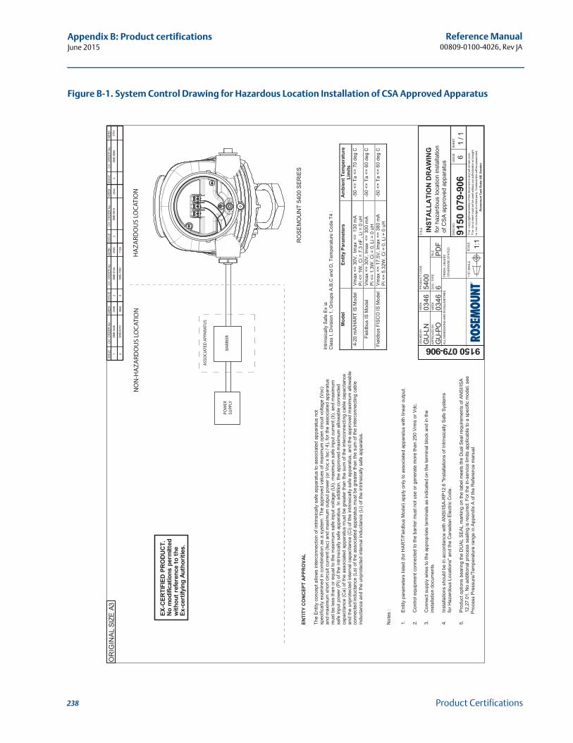
238
Reference Manual00809-0100-4026, Rev JA
Appendix B: Product certificationsJune 2015
Product Certifications
Figure B-1. System Control Drawing for Hazardous Location Installation of CSA Approved Apparatus
SME-
3445
0346
1
ISS
UE
CH
. OR
DE
R N
oW
EEK
ISS
UE
CH
. OR
DE
R N
oW
EEK
ISS
UE
CH
. OR
DE
R N
oW
EEK
ISS
UE
CH
. OR
DE
R N
oW
EEK
A3O
RIG
INA
L SI
ZE
GU
-LN
0346
5400
GU
-PO
6P
DF
9150 079-906
9150
079
-906
0346
INST
ALL
ATI
ON
DR
AW
ING
for h
azar
dous
loca
tion
inst
alla
tion
of C
SA
app
rove
d ap
para
tus
61
/ 1
ISSU
ED B
Y
APPR
OVE
D B
Y
WEE
K
WEE
K
PR
OD
UC
T C
OD
E
DO
C. T
YPE
FILE
TITL
E
DW
G N
O.
ISS
UE
SHEE
T
SCAL
E
1:1
1 ST
AN
GLE
FIN
ISH
, UN
LESS
OTH
ERW
ISE
STAT
ED:
ALL
DIM
ENSI
ON
S AR
E IN
MIL
LIM
ETR
ES.
The
cop
yrig
ht/o
wne
rshi
p of
this
doc
umen
t is
and
will
rem
ain
ours
.T
he d
ocum
ent m
ust n
ot b
e us
ed w
ithou
t our
aut
horiz
atio
n or
bro
ught
to t
he k
now
ledg
e of
a th
ird p
arty
. Con
trave
ntio
n w
ill be
pro
secu
ted.
Ro
sem
ou
nt
Tan
k R
ad
ar
AB
, S
wed
en
ASS
OC
IATE
D A
PPA
RATU
S
BA
RRIE
RPO
WER
SUPP
LY
HA
ZA
RDO
US
LOC
ATIO
N
NO
N-H
AZ
ARD
OU
S LO
CAT
ION
RO
SEM
OU
NT
5400
SER
IES
Intri
nsic
ally
Saf
e Ex
ia
C
lass
I, D
ivis
ion
1, G
roup
s A
,B,C
and
D, T
empe
ratu
re C
ode
T4 :
Mod
el
Entit
y Pa
ram
eter
s A
mbi
ent T
empe
ratu
re
Lim
its
4-20
mA/
HAR
T IS
Mod
el
Vmax
<=
30V,
Imax
<=
130
mA
P
i <=
1W, C
i = 7
.3 n
F, L
i = 0
uH
-5
0 <=
Ta
<= 7
0 de
g C
Fiel
dbus
IS M
odel
Vm
ax <
= 30
V, Im
ax <
= 30
0 m
A Pi
<=
1.3W
, Ci =
0, L
i = 0
uH
-5
0 <=
Ta
<= 6
0 de
g C
Fiel
dbus
FIS
CO
IS M
odel
V
max
<=
17.5
V, I
max
<=
380
mA
Pi
<=
5.32
W, C
i = 0
, Li =
0 u
H
-50
<= T
a <=
60
deg
C
2SM
E-51
3405
263
SME-
5514
0644
SME-
5880
0751
4
EX-C
ERTI
FIED
PR
OD
UC
T.N
o m
odifi
catio
ns p
erm
itted
with
out r
efer
ence
to th
eEx
-cer
tifyi
ng A
utho
ritie
s.
5SM
E-60
1908
406
SME-
7063
1123
ENTI
TY C
ON
CEP
T A
PPR
OVA
L Th
e En
tity
conc
ept a
llow
s in
terc
onne
ctio
n of
intri
nsic
ally
saf
e ap
para
tus
to a
ssoc
iate
d ap
para
tus
not
spec
ifica
lly e
xam
ined
in c
ombi
natio
n as
a s
yste
m. T
he a
ppro
ved
valu
es o
f max
imum
ope
n ci
rcui
t vol
tage
(Voc
)
and
max
imum
sho
rt ci
rcui
t cur
rent
(Isc
) and
max
imum
out
put p
ower
(or V
oc x
Isc
/ 4),
for t
he a
ssoc
iate
d ap
para
tus
mus
t be
less
than
or e
qual
to th
e m
axim
um s
afe
inpu
t vol
tage
(Ui),
max
imum
saf
e in
put c
urre
nt (I
i), a
nd m
axim
um
sa
fe in
put p
ower
(Pi)
of th
e in
trins
ical
ly s
afe
appa
ratu
s. In
add
ition
, the
app
rove
d m
axim
um a
llow
able
con
nect
ed
capa
cita
nce
(Ca)
of t
he a
ssoc
iate
d ap
para
tus
mus
t be
grea
ter t
han
the
sum
of t
he in
terc
onne
ctin
g ca
ble
capa
cita
nce
and
the
unpr
otec
ted
inte
rnal
cap
acita
nce
(Ci)
of th
e in
trins
ical
ly s
afe
appa
ratu
s, a
nd th
e ap
prov
ed m
axim
um a
llow
able
c
onne
cted
indu
ctan
ce (L
a) o
f the
ass
ocia
ted
appa
ratu
s m
ust b
e gr
eate
r tha
n th
e su
m o
f the
inte
rcon
nect
ing
cabl
e
indu
ctan
ce a
nd th
e un
prot
ecte
d in
tern
al in
duct
ance
(Li)
of th
e in
trins
ical
ly s
afe
appa
ratu
s.
N
otes
:
1.
E
ntity
par
amet
ers
liste
d (fo
r HA
RT/
Fiel
dbus
Mod
el) a
pply
onl
y to
ass
ocia
ted
appa
ratu
s w
ith li
near
out
put.
2.
C
ontro
l equ
ipm
ent c
onne
cted
to th
e ba
rrier
mus
t not
use
or g
ener
ate
mor
e th
an 2
50 V
rms
or V
dc.
3.
C
onne
ct s
uppl
y w
ires
to th
e ap
prop
riate
term
inal
s as
indi
cate
d on
the
term
inal
blo
ck a
nd in
the
in
stal
latio
n do
cum
ents
.
4.
In
stal
latio
ns s
houl
d be
in a
ccor
danc
e w
ith A
NS
I/IS
A-R
P12
.6 "I
nsta
llatio
ns o
f Int
rinsi
cally
Saf
e S
yste
ms
fo
r Haz
ardo
us L
ocat
ions
" and
the
Can
adia
n E
lect
ric C
ode.
5.
P
rodu
ct o
ptio
ns b
earin
g th
e D
UA
L S
EA
L m
arki
ng o
n th
e la
bel m
eets
the
Dua
l Sea
l req
uire
men
ts o
f AN
SI/I
SA
12.2
7.01
. No
addi
tiona
l pro
cess
sea
ling
is re
quire
d. F
or th
e in
-ser
vice
lim
its a
pplic
able
to a
spe
cific
mod
el, s
ee
Pro
cess
Pre
ssur
e/Te
mpe
ratu
re ra
nge
in A
ppen
dix
A o
f the
Ref
eren
ce m
anua
l.
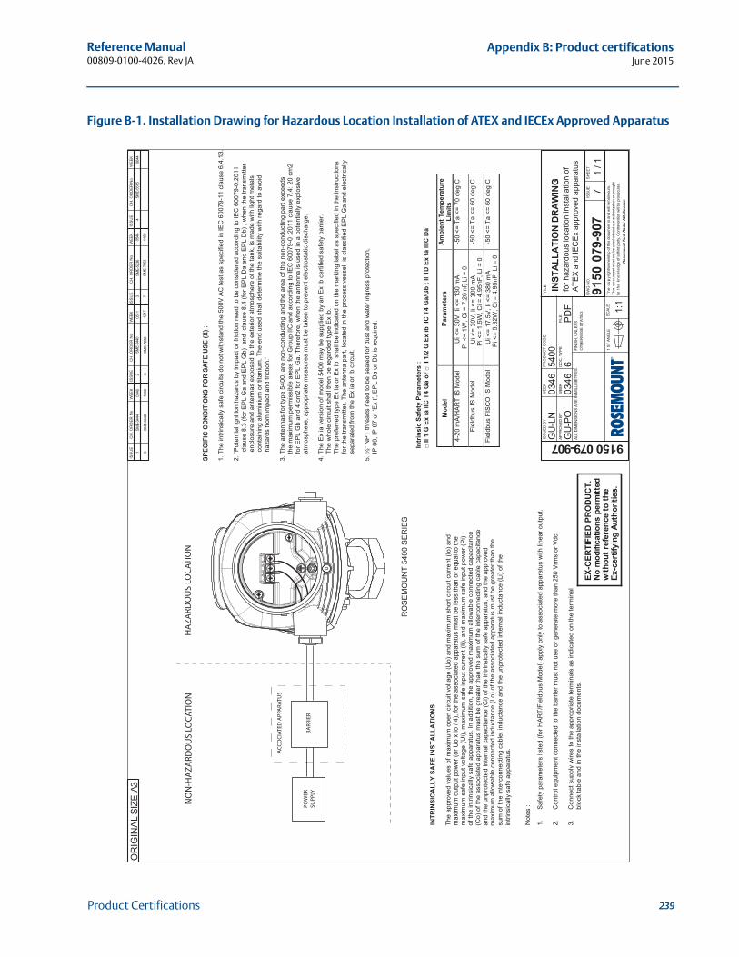
239
Reference Manual 00809-0100-4026, Rev JA
Appendix B: Product certificationsJune 2015
Product Certifications
Figure B-1. Installation Drawing for Hazardous Location Installation of ATEX and IECEx Approved ApparatusSM
E-34
44
03
46
1
ISS
UE
CH
. OR
DE
R N
oW
EEK
ISS
UE
CH
. OR
DE
R N
oW
EEK
ISS
UE
CH
. OR
DE
R N
oW
EEK
ISS
UE
CH
. OR
DE
R N
oW
EEK
A3O
RIG
INA
L SI
ZE
GU
-LN
0346
5400
GU
-PO
6P
DF
9150 079-907
9150
079
-907
0346
INST
ALL
ATI
ON
DR
AW
ING
for h
azar
dous
loca
tion
inst
alla
tion
of
ATE
X a
nd IE
CE
x ap
prov
ed a
ppar
atus
71
/ 1
ISSU
ED B
Y
APPR
OVE
D B
Y
WEE
K
WEE
K
PR
OD
UC
T C
OD
E
DO
C. T
YPE
FILE
TITL
E
DW
G N
O.
ISS
UE
SHEE
T
SCAL
E
1:1
1 ST
AN
GLE
FIN
ISH
, UN
LESS
OTH
ERW
ISE
STAT
ED:
ALL
DIM
ENSI
ON
S AR
E IN
MIL
LIM
ETR
ES.
The
cop
yrig
ht/o
wne
rshi
p of
this
doc
umen
t is
and
will
rem
ain
ours
.T
he d
ocum
ent m
ust n
ot b
e us
ed w
ithou
t our
aut
horiz
atio
n or
bro
ught
to t
he k
now
ledg
e of
a th
ird p
arty
. Con
trave
ntio
n w
ill be
pro
secu
ted.
Ro
sem
ou
nt
Tan
k R
ad
ar
AB
, S
wed
en
AC
CO
CIA
TED
APP
ARA
TUS
BA
RRIE
RPO
WER
SUPP
LY
HA
ZA
RDO
US
LOC
ATIO
N
NO
N-H
AZ
ARD
OU
S LO
CAT
ION
RO
SEM
OU
NT
5400
SER
IES
EX-C
ERTI
FIED
PR
OD
UC
T.N
o m
odifi
catio
ns p
erm
itted
with
out r
efer
ence
to th
eEx
-cer
tifyi
ng A
utho
ritie
s.
Intr
insi
c Sa
fety
Par
amet
ers
:
Mod
el
Para
met
ers
A
mie
nt T
empe
ratu
re
Lim
its
4-20
mA/
HA
RT
IS M
odel
U
i <=
30V
, Ii <
= 13
0 m
A
Pi
<=
1W, C
i = 7
.26
nF, L
i = 0
-50
<= T
a <=
70
deg
C
Fiel
dbus
IS M
odel
Pi <
= 1.
5W, C
i = 4
.95n
F, L
i = 0
-50
<= T
a <=
60
deg
C
Fiel
dbus
FIS
CO
IS M
odel
Pi
<=
5.32
W, C
i = 4
.95n
F, L
i = 0
-50
<= T
a <=
60
deg
C
Ui <
= 30
V, I
i <=
300
mA
Ui <
= 17
.5V
, Ii <
= 38
0 m
A
SME-
6440
205
113
SME-
5236
0548
4SM
E-55
1506
44
5SM
E-64
4010
486
SME-
7230
1217
7SM
E-76
5314
09
INTR
INSI
CA
LLY
SAFE
INST
ALL
ATI
ON
S
The
appr
oved
val
ues
of m
axim
um o
pen
circ
uit v
olta
ge (U
o) a
nd m
axim
um s
hort
circ
uit c
urre
nt (I
o) a
nd
m
axim
um o
utpu
t pow
er (o
r Uo
x Io
/ 4)
, for
the
asso
ciat
ed a
ppar
atus
mus
t be
less
than
or e
qual
to th
e
m
axim
um s
afe
inpu
t vol
tage
(Ui),
max
imum
saf
e in
put c
urre
nt (I
i), a
nd m
axim
um s
afe
inpu
t pow
er (P
i)
of th
e in
trins
ical
ly s
afe
appa
ratu
s. In
add
ition
, the
app
rove
d m
axim
um a
llow
able
con
nect
ed c
apac
itanc
e (C
o) o
f the
ass
ocia
ted
appa
ratu
s m
ust b
e gr
eate
r tha
n th
e su
m o
f the
inte
rcon
nect
ing
cabl
e ca
paci
tanc
e an
d th
e un
prot
ecte
d in
tern
al c
apac
itanc
e (C
i) of
the
intri
nsic
ally
saf
e ap
para
tus,
and
the
appr
oved
max
imum
allo
wab
le c
onne
cted
indu
ctan
ce (L
o) o
f the
ass
ocia
ted
appa
ratu
s m
ust b
e gr
eate
r tha
n th
e
sum
of t
he in
terc
onne
ctin
g ca
ble
indu
ctan
ce a
nd th
e un
prot
ecte
d in
tern
al in
duct
ance
(Li)
of th
e in
trins
ical
ly s
afe
appa
ratu
s.
N
otes
:
1.
S
afet
y pa
ram
eter
s lis
ted
(for H
AR
T/Fi
eldb
us M
odel
) app
ly o
nly
to a
ssoc
iate
d ap
para
tus
with
line
ar o
utpu
t. 2.
Con
trol e
quip
men
t con
nect
ed to
the
barri
er m
ust n
ot u
se o
r gen
erat
e m
ore
than
250
Vrm
s or
Vdc
.
3.
C
onne
ct s
uppl
y w
ires
to th
e ap
prop
riate
term
inal
s as
indi
cate
d on
the
term
inal
bl
ock
tabl
e an
d in
the
inst
alla
tion
docu
men
ts.
SPEC
IFIC
CO
ND
ITIO
NS
FOR
SA
FE U
SE (X
) :
1. T
he in
trins
ical
ly s
afe
circ
uits
do
not w
ithst
and
the
500V
AC
test
as
spec
ified
in IE
C 6
0079
-11
clau
se 6
.4.1
3.
2. “P
oten
tial i
gniti
on h
azar
ds b
y im
pact
or f
rictio
n ne
ed to
be
cons
ider
ed a
ccor
ding
to IE
C 6
0079
-0:2
011
c
laus
e 8.
3 (fo
r EP
L G
a an
d E
PL
Gb)
and
cla
use
8.4
(for E
PL
Da
and
EP
L D
b) ,
whe
n th
e tra
nsm
itter
enc
losu
re a
nd a
nten
nas
expo
sed
to th
e ex
terio
r atm
osph
ere
of th
e ta
nk, i
s m
ade
with
ligh
t met
als
c
onta
inin
g al
umin
ium
or t
itani
um. T
he e
nd u
sed
shal
l det
erm
ine
the
suita
bilit
y w
ith re
gard
to a
void
haz
ards
from
impa
ct a
nd fr
ictio
n.”
3. T
he a
nten
nas
for t
ype
5400
, are
non
-con
duct
ing
and
the
area
of t
he n
on-c
ondu
ctin
g pa
rt ex
ceed
s
the
max
imum
per
mis
sibl
e ar
eas
for G
roup
IIC
and
acc
ordi
ng to
IEC
600
79-0
.201
1 cl
ause
7.4
: 20
cm2
fo
r EP
L G
b an
d 4
cm2
for E
PL
Ga.
The
refo
re, w
hen
the
ante
nna
is u
sed
in a
pot
entia
lly e
xplo
sive
atm
osph
ere,
app
ropr
iate
mea
sure
s m
ust b
e ta
ken
to p
reve
nt e
lect
rost
atic
dis
char
ge.
4. T
he E
x ia
ver
sion
of m
odel
540
0 m
ay b
e su
pplie
d by
an
Ex
ib c
ertif
ied
safe
ty b
arrie
r.
The
who
le c
ircui
t sha
ll th
en b
e re
gard
ed ty
pe E
x ib
.
The
pre
ferr
ed ty
pe E
x ia
or E
x ib
sha
ll be
indi
cate
d on
the
mar
king
labe
l as
spec
ified
in th
e in
stru
ctio
ns
fo
r the
tran
smitt
er. T
he a
nten
na p
art,
loca
ted
in th
e pr
oces
s ve
ssel
, is
clas
sifie
d E
PL
Ga
and
elec
trica
lly
s
epar
ated
from
the
Ex
ia o
r ib
circ
uit.
5. ½
” NP
T th
read
s ne
ed to
be
seal
ed fo
r dus
t and
wat
er in
gres
s pr
otec
tion,
IP 6
6, IP
67
or ‘E
x t’,
EP
L D
a or
Db
is re
quire
d.
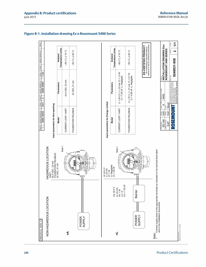
240
Reference Manual00809-0100-4026, Rev JA
Appendix B: Product certificationsJune 2015
Product Certifications
Figure B-1. Installation drawing Ex n Rosemount 5400 Series
OR
IGIN
AL
SIZE
A3
2011
-06-
28 1
4:34
92
4003
1-95
8_I0
2_P0
1_A
3.D
OC
X
ISSU
E M
OD
IF. O
RD
ER N
O.
WEE
K
ISSU
E M
OD
IF. O
RD
ER N
O.
WEE
K
ISSU
E M
OD
IF. O
RD
ER N
O.
WEE
K
1 S
ME
-585
9 10
41
2 S
ME
-686
4 11
26
ISSU
ED B
Y
WEE
K
DO
C. T
YPE
PR
OD
UC
T C
OD
E TI
TLE
EE-V
M
1041
6
5400
IN
STA
LLA
TIO
N D
RA
WIN
G E
xn
RO
SEM
OU
NT
5400
SER
IES
APP
RO
VED
BY
W
EEK
FI
LE
EA
P
1041
W
ord
The
copy
right
/ow
ners
hip
of th
is d
ocum
ent i
s an
d w
ill re
mai
n ou
rs. T
he d
ocum
ent m
ust n
ot
be u
sed
with
out o
ur a
utho
rizat
ion
or b
roug
ht
to th
e kn
owle
dge
of a
third
par
ty.
Con
trave
ntio
n w
ill b
e pr
osec
uted
. R
osem
ou
nt
Tan
k R
ad
ar
AB
, S
wed
en
DO
C N
O.
ISSU
E PA
GE
9240
031-
958
2 1/
1
N
ON
-HA
ZAR
DO
US
LO
CA
TIO
N
HA
ZAR
DO
US
LO
CA
TIO
N
HA
RT:
42
.4 V
DC
, 23
mA
FO
UN
DA
TIO
N F
IELD
BU
S:
32 V
DC
, 21
mA
Not
e 1
nA
Ui:
42.4
V
Ii:
23
mA
P
i: 1
W
Li: N
eglig
ible
Uo:
42.
4 V
C
i: 7.
25 n
F nL
Io
: 23
mA
N
ote
1
Po:
1 W
Lo >
0
C
o >
7.25
nF
N
otes
: 1
Con
nect
sup
ply
wire
s to
the
appr
opria
te te
rmin
als
as in
dica
ted
on th
e te
rmin
al b
lock
labe
l an
d in
the
inst
alla
tion
docu
men
ts.
Inpu
t par
amet
ers
for N
on-s
park
ing
Mod
el
Para
met
ers
Am
bien
t Te
mpe
ratu
re L
imits
CU
RR
EN
T LO
OP
/ H
AR
T
42.4
VD
C, 2
3 m
A,
–5
0 ≤
T a ≤
70
°C
FO
UN
DA
TIO
N F
IELD
BU
S
32
VD
C, 2
1 m
A
–5
0 ≤
T a ≤
60
°C
In
put p
aram
eter
s fo
r Ene
rgy
Lim
ited
M
odel
Pa
ram
eter
s A
mbi
ent
Tem
pera
ture
Lim
its
C
UR
RE
NT
LOO
P /
HA
RT
U
i = 4
2.4
V, I i
= 2
3 m
A, P
i = 1
.0 W
C
i = 7
.25
nF, L
i: N
eglig
ible
–5
0 ≤
T a ≤
70
°C
FO
UN
DA
TIO
N F
IELD
BU
S
U
i = 3
2 V
, Ii =
21
mA
, Pi =
0.7
W
Ci =
4.9
5 nF
, Li:
Neg
ligib
le
–5
0 ≤
T a ≤
60
°C
PO
WE
R
SU
PP
LY
EX-C
ERTI
FIED
PR
OD
UC
T N
o m
odifi
catio
ns p
erm
itted
with
out
refe
renc
e to
the
Ex-
certi
fyin
g A
utho
ritie
s.
PO
WE
R
SU
PP
LY
Bar
rier
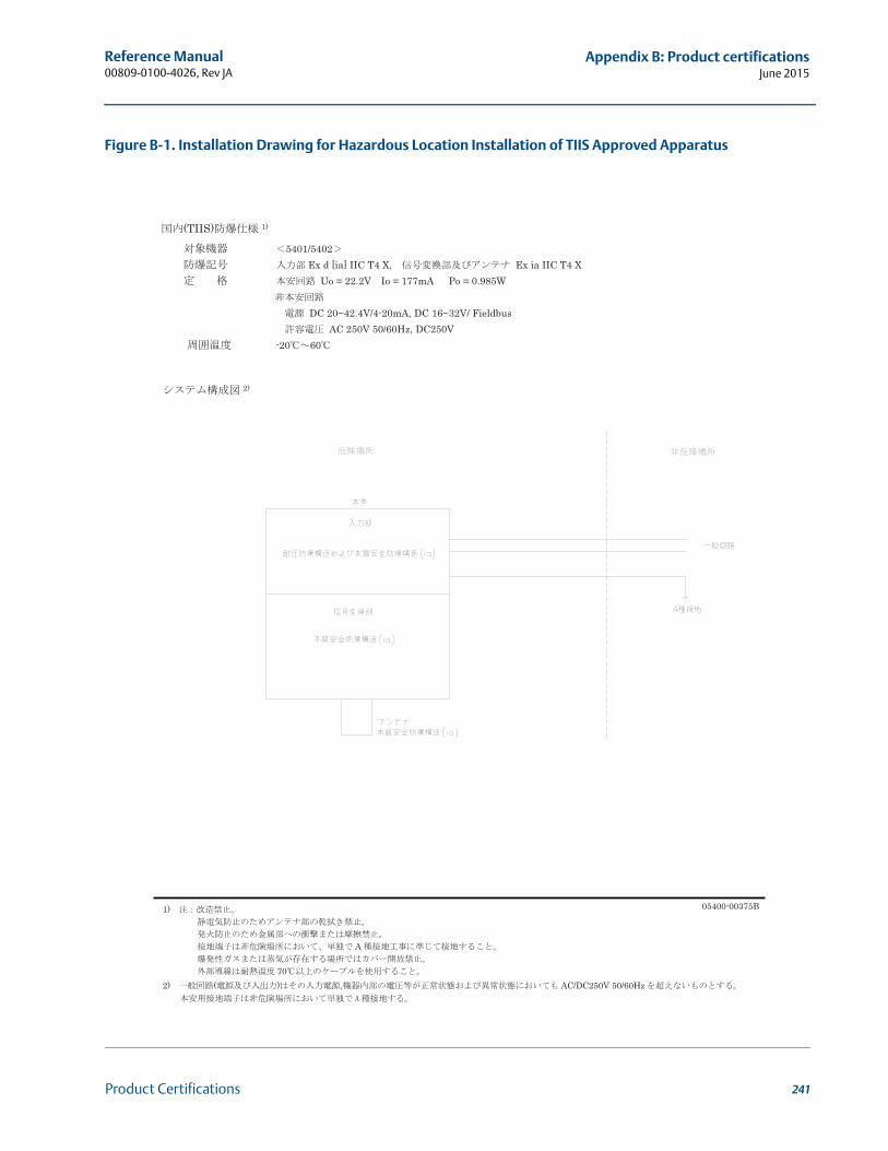
241
Reference Manual 00809-0100-4026, Rev JA
Appendix B: Product certificationsJune 2015
Product Certifications
Figure B-1. Installation Drawing for Hazardous Location Installation of TIIS Approved Apparatus
(TIIS) 1) 5401/5402
Ex d [ia] IIC T4 X, Ex ia IIC T4 X Uo = 22.2V Io = 177mA Po = 0.985W
DC 20~42.4V/4-20mA, DC 16~32V/ Fieldbus
AC 250V 50/60Hz, DC250V -20 60
1) 05400-00375B
A
70 2) ( ) , AC/DC250V 50/60Hz
2)

242
Reference Manual00809-0100-4026, Rev JA
Appendix B: Product certificationsJune 2015
Product Certifications
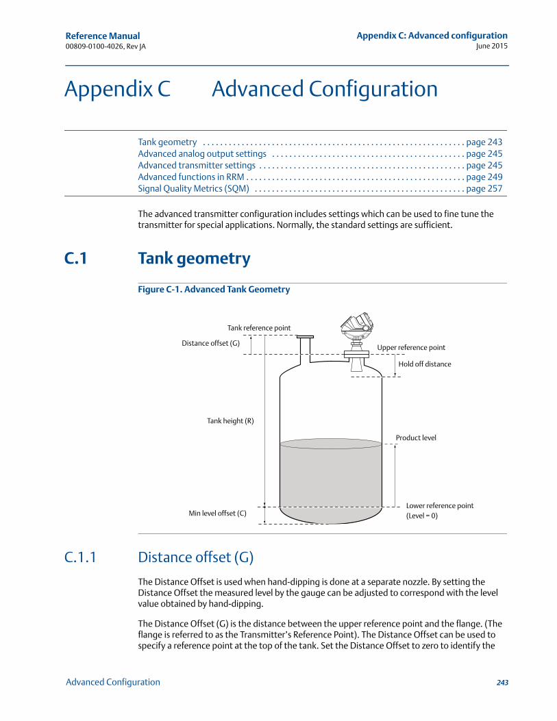
Reference Manual 00809-0100-4026, Rev JA
Appendix C: Advanced configurationJune 2015
Appendix C Advanced Configuration
Tank geometry . . . . . . . . . . . . . . . . . . . . . . . . . . . . . . . . . . . . . . . . . . . . . . . . . . . . . . . . . . . . . page 243Advanced analog output settings . . . . . . . . . . . . . . . . . . . . . . . . . . . . . . . . . . . . . . . . . . . . . page 245Advanced transmitter settings . . . . . . . . . . . . . . . . . . . . . . . . . . . . . . . . . . . . . . . . . . . . . . . . page 245Advanced functions in RRM . . . . . . . . . . . . . . . . . . . . . . . . . . . . . . . . . . . . . . . . . . . . . . . . . . . page 249Signal Quality Metrics (SQM) . . . . . . . . . . . . . . . . . . . . . . . . . . . . . . . . . . . . . . . . . . . . . . . . . page 257
The advanced transmitter configuration includes settings which can be used to fine tune the transmitter for special applications. Normally, the standard settings are sufficient.
C.1 Tank geometry
Figure C-1. Advanced Tank Geometry
C.1.1 Distance offset (G)
The Distance Offset is used when hand-dipping is done at a separate nozzle. By setting the Distance Offset the measured level by the gauge can be adjusted to correspond with the level value obtained by hand-dipping.
The Distance Offset (G) is the distance between the upper reference point and the flange. (The flange is referred to as the Transmitter’s Reference Point). The Distance Offset can be used to specify a reference point at the top of the tank. Set the Distance Offset to zero to identify the
Tank height (R)
Product level
Tank reference point
Distance offset (G)
Min level offset (C)
Upper reference point
Hold off distance
Lower reference point(Level = 0)
243Advanced Configuration
Reference Manual00809-0100-4026, Rev JA
Appendix C: Advanced configurationJune 2015
lower side of the device flange as the upper reference point. The Distance Offset is defined as positive if an upper reference point above the Upper Reference Point is used.
C.1.2 Minimum level offset (C)
The Minimum Level Offset (C) defines a lower null zone which extends the measurement range beyond the Lower Reference Point to the tank bottom. The Minimum Level Offset is the distance between the Lower Reference Point (Level = 0) and the minimum accepted level at the tank bottom. Set the Minimum Level Offset to zero to use the tank bottom as the Lower Reference Point. This case corresponds to the standard tank geometry configuration.
Note that the tank height must be measured to the Lower Reference Point regardless if it is located at the tank bottom, or at an elevated point.
C.1.3 Hold off distance
This parameter should only be changed if there are disturbing objects close to the antenna. No valid measurements are possible above the Hold Off Distance. By increasing the Hold Off Distance, the measuring range is reduced. See “Hold off setting” on page 256 for more information.
C.1.4 Calibration distance
The Calibration Distance is defaulted to zero. It is used to adjust the transmitter so measured levels match hand-dipped or otherwise known product levels. Normally, a minor adjustment is necessary. There may, for example, be a deviation between the actual tank height and the value from tank drawings, which are usually stored in the transmitter database.
Non-metallic (for example, plastic) vessels and installation geometry may introduce an offset for the zero reference point. This offset may be up to ± 10 mm. The offset can be compensated for using Calibration Distance.
244 Advanced Configuration
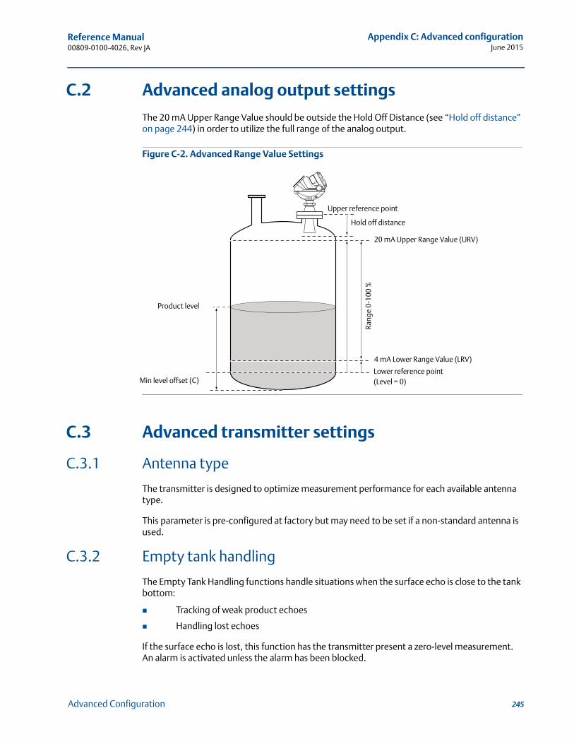
Reference Manual 00809-0100-4026, Rev JA
Appendix C: Advanced configurationJune 2015
C.2 Advanced analog output settings
The 20 mA Upper Range Value should be outside the Hold Off Distance (see “Hold off distance” on page 244) in order to utilize the full range of the analog output.
Figure C-2. Advanced Range Value Settings
C.3 Advanced transmitter settings
C.3.1 Antenna type
The transmitter is designed to optimize measurement performance for each available antenna type.
This parameter is pre-configured at factory but may need to be set if a non-standard antenna is used.
C.3.2 Empty tank handling
The Empty Tank Handling functions handle situations when the surface echo is close to the tank bottom:
Tracking of weak product echoes
Handling lost echoes
If the surface echo is lost, this function has the transmitter present a zero-level measurement. An alarm is activated unless the alarm has been blocked.
20 mA Upper Range Value (URV)
Product level
4 mA Lower Range Value (LRV)Ra
nge
0-10
0 %
Upper reference point
Min level offset (C)
Hold off distance
Lower reference point(Level = 0)
245Advanced Configuration
Reference Manual00809-0100-4026, Rev JA
Appendix C: Advanced configurationJune 2015
Empty tank detection area
The Empty Tank Detection Area is the range within a lower limit of 16 in. (400 mm) and a higher limit of 39 in. (1000 mm) above the tank bottom. If the surface echo is lost in this region, the tank is considered empty (the device enters Empty Tank State) and the transmitter presents a zero level reading.
If the tank is empty, the transmitter searches double the Empty Tank Detection Area for the product surface. When a new echo is found, it is considered to be the product surface.
It is important that there are no disturbances in this area, but if there are, they may need to be filtered out.
This function requires the Bottom Echo Visible function to be disabled. The current Empty Tank Detection Area value is shown in Advanced Setup in RRM and can be adjusted manually, if required. See “Empty tank detection area” on page 250.
Bottom echo visible
Only set this parameter if the bottom echo is visible. Setting this parameter will use the bottom echo as a disturbance echo to facilitate tracking of weak surface echoes close to the tank bottom.
Check that the gauge detects the tank bottom when the tank is empty before activating this function. See “Bottom echo visible” on page 249.
Tank bottom projection
This function handles situations close to the tank bottom and may enhance measurement performance in the tank bottom region. In this region, the signal from the actual tank bottom may be significantly stronger than the measurement signal from the product surface, in some situations.
Extra echo
Extra Echo Detection is used for tanks with domed or conical bottom types and when there is no strong echo from the tank bottom when the tank is empty and an echo beneath the actual tank bottom can sometimes be seen. See “Extra echo function” on page 251.
Level alarm is not set when tank is empty
If the echo from the product is lost in the area close to the tank bottom (Empty Tank Detection Area), the device enters Empty Tank State and triggers an alarm. Two types of alarms are triggered:
Invalid Level (can be seen in the Diagnostics window)
The Analog Output enters Alarm Mode
246 Advanced Configuration
Reference Manual 00809-0100-4026, Rev JA
Appendix C: Advanced configurationJune 2015
C.3.3 Full tank handling
Full tank detection area
This parameter defines a range where the surface echo can be lost. If the echo is lost in this range, the tank is considered full (the device enters Full Tank State) and the device presents maximum level indication.
When the tank is full, the device searches double the Full Tank Detection Area for the product surface. When a new echo is found in this range, it is identified as the product surface.
It is important to filter out any disturbances in this area.
Level above hold off distance possible
This function should be enabled if the level can rise above the Hold Off Distance/UNZ and it is necessary to display the tank as full in that case. Normally, the device will be able to track the surface and the product level will never rise to that height. If the function is not enabled and the surface is lost at the top of the tank, the device searches the whole tank for a surface echo.
NoteMeasurements are not performed within the Hold Off Distance/UNZ region.
Level alarm is not set when tank is full
If the surface echo is lost, close to the top of the tank. The level value will normally be displayed as “invalid.” This parameter should be set to suppress the “invalid” display.
NoteSetting this parameter disables the analog output so it does not enter alarm mode for invalid levels close to the antenna.
See “Full tank handling” on page 253 for more information.
C.3.4 Double bounce
Some radar waves are reflected at the surface and then reflected against the tank roof and back to the surface before being detected by the transmitter. Normally, these signals have a low amplitude and are ignored by the transmitter. For spherical and horizontal cylinder tanks however, the amplitude may be strong enough for the transmitter to interpret the double bounce as the surface echo. Setting the Double Bounce Possible parameter can solve this type of measurement situation. This function should only be used if double bounces cannot be corrected by changing the mechanical installation. See “Double bounce” on page 254 for more information.
247Advanced Configuration
Reference Manual00809-0100-4026, Rev JA
Appendix C: Advanced configurationJune 2015
C.3.5 Surface echo tracking
Slow search
This variable controls how to search for the surface when a surface echo is lost. With this parameter set, the transmitter starts searching for the surface at the last known level and gradually increases the search region until the surface is found. If this variable is not set, the transmitter searches the whole tank. This parameter is typically used for tanks with turbulent conditions.
Slow search speed
This parameter indicates the speed the search region (Slow Search window) is expanded when the Slow Search function is active.
Double surface
Indicates that there are two liquids or foam in the tank resulting in two reflecting surfaces. The upper liquid or foam layer must be partially transparent to the radar signal.
The Select Lower Surface parameter specifies the surface layer selected as the surface.
Upper product dielectric constant
This is the dielectric constant for the upper product if there is a double surface situation. A more precise value results in better accuracy for the lower surface level.
Select lower surface
This function should only be used if Double Surface is set. If Select Lower Surface is set, the lower surface is identified as the product surface. If not, the upper surface is used.
Echo timeout
Echo Timeout defines the time, in seconds, after the echo has been lost, before the transmitter starts searching for a surface echo. The transmitter will not start searching, or trigger any alarms, until this time has elapsed.
Close distance window
This parameter defines a window centered at the current surface position where new surface echo candidates can be selected. The size of the window is ±CloseDist. Echoes outside this window will not be considered surface echoes and the transmitter will jump to the strongest echo inside this window. If there are rapid level changes in the tank, the value of the Close Distance Window can be increased to prevent the transmitter from missing level changes. On the other hand, a large value may cause the transmitter to select an invalid echo as the surface echo.
248 Advanced Configuration
Reference Manual 00809-0100-4026, Rev JA
Appendix C: Advanced configurationJune 2015
C.3.6 Filter settings
Damping value
The Damping Value parameter determines how quickly the transmitter responds to level changes and how robust the measurement signal is against noise. A damping value of 10 indicates that in 10 seconds the output from the transmitter is approximately 63 % of the new level value. Consequently, when there are rapid level changes in the tank, it may be necessary to decrease the Damping Value for the transmitter to track the surface. In noisy environments, with low level rates, it may be best to increase the damping value for a stable output signal.
Activate jump filter
The Jump Filter is typically used for turbulent surface applications where it smooths the echo tracking as the level passes, for example, an agitator. If the surface echo is lost and a new surface echo is found, the Jump Filter has the transmitter wait before jumping to the new echo so it can be validated. During that time the new echo has to be considered a valid echo.
C.4 Advanced functions in RRM
C.4.1 Empty tank handling
Bottom echo visible
The Bottom Echo Visible... parameter allows the transmitter to separate the product surface from the tank bottom by identifying the bottom echo as a disturbance echo. This is useful for products relatively transparent for microwaves, such as oil. For non-transparent products, such as water, there is no visible bottom echo until the tank is empty.
To enable this function:
1. Disable the Use Automatic Empty Tank Handling Settings option.
2. Select the Bottom Echo Visible if Tank is Empty check-box.
Only use this function for tanks with a Flat bottom type where the radar echo from the tank bottom is clearly visible. If there is no distinct bottom echo, even if the tank is empty, this parameter should be disabled. Otherwise, if the surface echo is temporarily lost, the transmitter starts searching for the product surface in the tank and may incorrectly interpret any object as the surface.
The spectrum function in the RRM program can be used to check if the gauge detects the tank bottom in an empty tank.
249Advanced Configuration
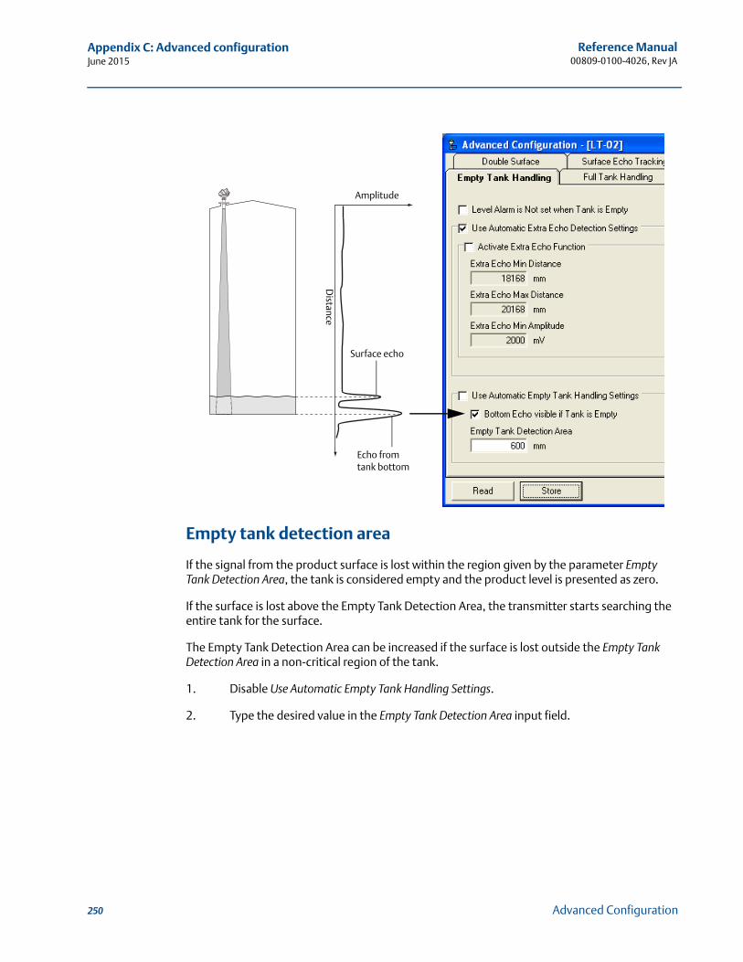
Reference Manual00809-0100-4026, Rev JA
Appendix C: Advanced configurationJune 2015
Empty tank detection area
If the signal from the product surface is lost within the region given by the parameter Empty Tank Detection Area, the tank is considered empty and the product level is presented as zero.
If the surface is lost above the Empty Tank Detection Area, the transmitter starts searching the entire tank for the surface.
The Empty Tank Detection Area can be increased if the surface is lost outside the Empty Tank Detection Area in a non-critical region of the tank.
1. Disable Use Automatic Empty Tank Handling Settings.
2. Type the desired value in the Empty Tank Detection Area input field.
Amplitude
Distance
Echo from tank bottom
Surface echo
250 Advanced Configuration
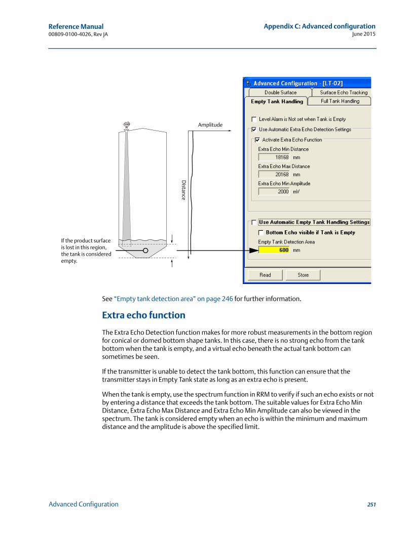
Reference Manual 00809-0100-4026, Rev JA
Appendix C: Advanced configurationJune 2015
See “Empty tank detection area” on page 246 for further information.
Extra echo function
The Extra Echo Detection function makes for more robust measurements in the bottom region for conical or domed bottom shape tanks. In this case, there is no strong echo from the tank bottom when the tank is empty, and a virtual echo beneath the actual tank bottom can sometimes be seen.
If the transmitter is unable to detect the tank bottom, this function can ensure that the transmitter stays in Empty Tank state as long as an extra echo is present.
When the tank is empty, use the spectrum function in RRM to verify if such an echo exists or not by entering a distance that exceeds the tank bottom. The suitable values for Extra Echo Min Distance, Extra Echo Max Distance and Extra Echo Min Amplitude can also be viewed in the spectrum. The tank is considered empty when an echo is within the minimum and maximum distance and the amplitude is above the specified limit.
Amplitude
Distance
If the product surface is lost in this region, the tank is considered empty.
251Advanced Configuration
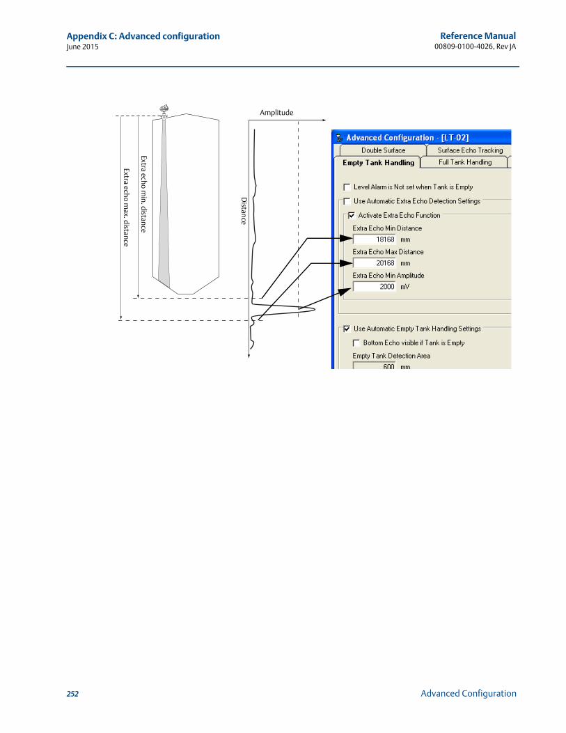
Reference Manual00809-0100-4026, Rev JA
Appendix C: Advanced configurationJune 2015
Amplitude
Distance
Extra echo min. distance
Extra echo max. distance
252 Advanced Configuration
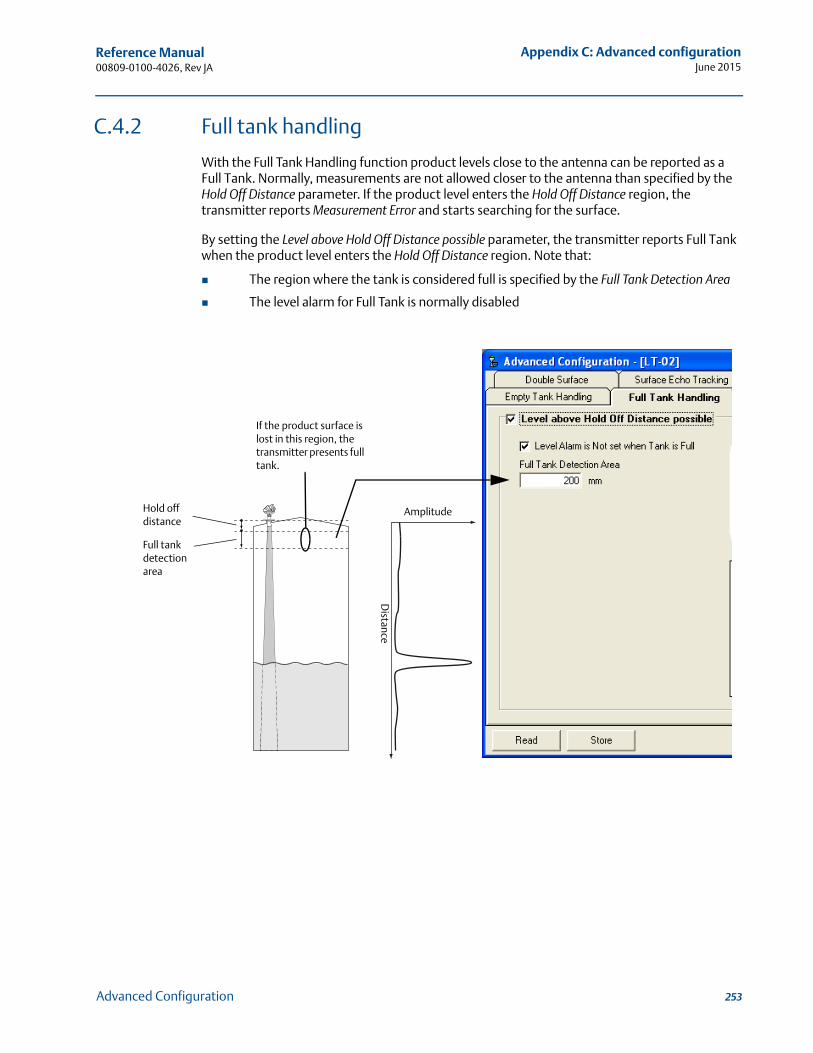
Reference Manual 00809-0100-4026, Rev JA
Appendix C: Advanced configurationJune 2015
C.4.2 Full tank handling
With the Full Tank Handling function product levels close to the antenna can be reported as a Full Tank. Normally, measurements are not allowed closer to the antenna than specified by the Hold Off Distance parameter. If the product level enters the Hold Off Distance region, the transmitter reports Measurement Error and starts searching for the surface.
By setting the Level above Hold Off Distance possible parameter, the transmitter reports Full Tank when the product level enters the Hold Off Distance region. Note that:
The region where the tank is considered full is specified by the Full Tank Detection Area
The level alarm for Full Tank is normally disabled
Amplitude
Distance
If the product surface is lost in this region, the transmitter presents full tank.
Full tank detection area
Hold off distance
253Advanced Configuration
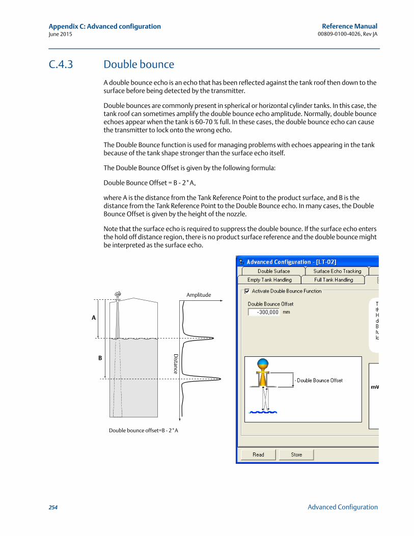
Reference Manual00809-0100-4026, Rev JA
Appendix C: Advanced configurationJune 2015
C.4.3 Double bounce
A double bounce echo is an echo that has been reflected against the tank roof then down to the surface before being detected by the transmitter.
Double bounces are commonly present in spherical or horizontal cylinder tanks. In this case, the tank roof can sometimes amplify the double bounce echo amplitude. Normally, double bounce echoes appear when the tank is 60-70 % full. In these cases, the double bounce echo can cause the transmitter to lock onto the wrong echo.
The Double Bounce function is used for managing problems with echoes appearing in the tank because of the tank shape stronger than the surface echo itself.
The Double Bounce Offset is given by the following formula:
Double Bounce Offset = B - 2*A,
where A is the distance from the Tank Reference Point to the product surface, and B is the distance from the Tank Reference Point to the Double Bounce echo. In many cases, the Double Bounce Offset is given by the height of the nozzle.
Note that the surface echo is required to suppress the double bounce. If the surface echo enters the hold off distance region, there is no product surface reference and the double bounce might be interpreted as the surface echo.
A
B
Double bounce offset=B - 2*A
Amplitude
Distance
254 Advanced Configuration
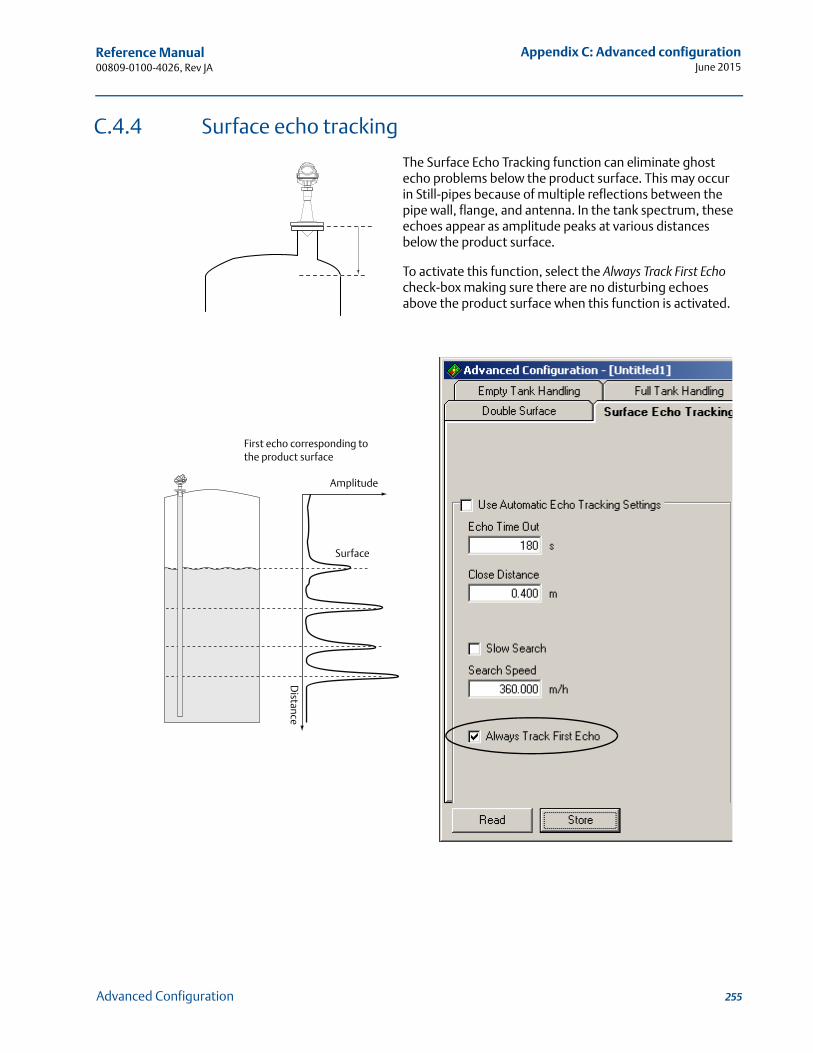
Reference Manual 00809-0100-4026, Rev JA
Appendix C: Advanced configurationJune 2015
C.4.4 Surface echo tracking
The Surface Echo Tracking function can eliminate ghost echo problems below the product surface. This may occur in Still-pipes because of multiple reflections between the pipe wall, flange, and antenna. In the tank spectrum, these echoes appear as amplitude peaks at various distances below the product surface.
To activate this function, select the Always Track First Echo check-box making sure there are no disturbing echoes above the product surface when this function is activated.
Amplitude
Distance
First echo corresponding to the product surface
Surface
255Advanced Configuration
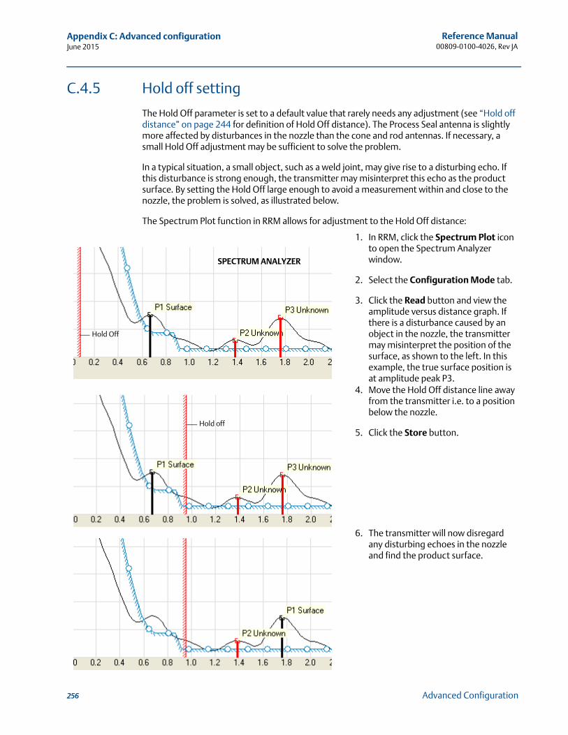
Reference Manual00809-0100-4026, Rev JA
Appendix C: Advanced configurationJune 2015
C.4.5 Hold off setting
The Hold Off parameter is set to a default value that rarely needs any adjustment (see “Hold off distance” on page 244 for definition of Hold Off distance). The Process Seal antenna is slightly more affected by disturbances in the nozzle than the cone and rod antennas. If necessary, a small Hold Off adjustment may be sufficient to solve the problem.
In a typical situation, a small object, such as a weld joint, may give rise to a disturbing echo. If this disturbance is strong enough, the transmitter may misinterpret this echo as the product surface. By setting the Hold Off large enough to avoid a measurement within and close to the nozzle, the problem is solved, as illustrated below.
The Spectrum Plot function in RRM allows for adjustment to the Hold Off distance:
1. In RRM, click the Spectrum Plot icon to open the Spectrum Analyzer window.
2. Select the Configuration Mode tab.
3. Click the Read button and view the amplitude versus distance graph. If there is a disturbance caused by an object in the nozzle, the transmitter may misinterpret the position of the surface, as shown to the left. In this example, the true surface position is at amplitude peak P3.
4. Move the Hold Off distance line away from the transmitter i.e. to a position below the nozzle.
5. Click the Store button.
6. The transmitter will now disregard any disturbing echoes in the nozzle and find the product surface.
Hold Off
SPECTRUM ANALYZER
Hold off
256 Advanced Configuration
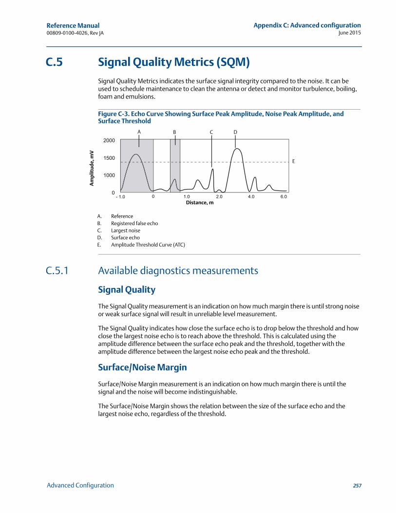
Reference Manual 00809-0100-4026, Rev JA
Appendix C: Advanced configurationJune 2015
C.5 Signal Quality Metrics (SQM)
Signal Quality Metrics indicates the surface signal integrity compared to the noise. It can be used to schedule maintenance to clean the antenna or detect and monitor turbulence, boiling, foam and emulsions.
Figure C-3. Echo Curve Showing Surface Peak Amplitude, Noise Peak Amplitude, and Surface Threshold
C.5.1 Available diagnostics measurements
Signal Quality
The Signal Quality measurement is an indication on how much margin there is until strong noise or weak surface signal will result in unreliable level measurement.
The Signal Quality indicates how close the surface echo is to drop below the threshold and how close the largest noise echo is to reach above the threshold. This is calculated using the amplitude difference between the surface echo peak and the threshold, together with the amplitude difference between the largest noise echo peak and the threshold.
Surface/Noise Margin
Surface/Noise Margin measurement is an indication on how much margin there is until the signal and the noise will become indistinguishable.
The Surface/Noise Margin shows the relation between the size of the surface echo and the largest noise echo, regardless of the threshold.
A
Am
plit
ud
e, m
V
Distance, m
A. ReferenceB. Registered false echoC. Largest noiseD. Surface echoE. Amplitude Threshold Curve (ATC)
B C D
E
257Advanced Configuration
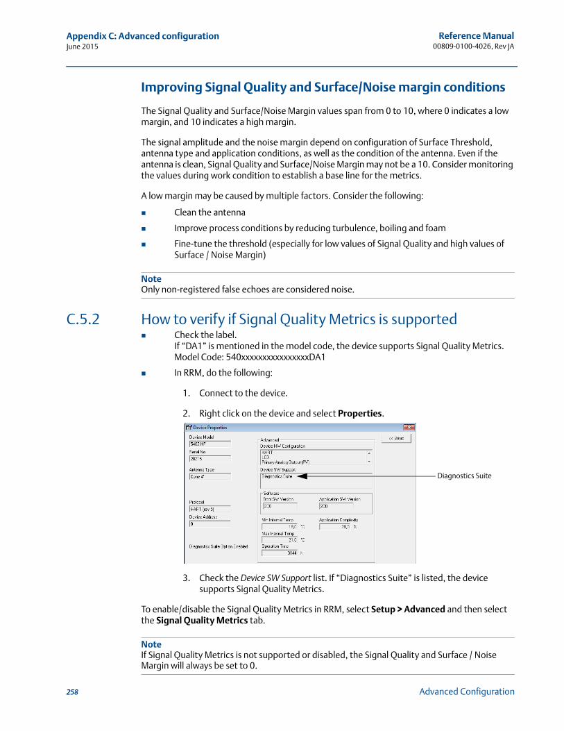
Reference Manual00809-0100-4026, Rev JA
Appendix C: Advanced configurationJune 2015
Improving Signal Quality and Surface/Noise margin conditions
The Signal Quality and Surface/Noise Margin values span from 0 to 10, where 0 indicates a low margin, and 10 indicates a high margin.
The signal amplitude and the noise margin depend on configuration of Surface Threshold, antenna type and application conditions, as well as the condition of the antenna. Even if the antenna is clean, Signal Quality and Surface/Noise Margin may not be a 10. Consider monitoring the values during work condition to establish a base line for the metrics.
A low margin may be caused by multiple factors. Consider the following:
Clean the antenna
Improve process conditions by reducing turbulence, boiling and foam
Fine-tune the threshold (especially for low values of Signal Quality and high values of Surface / Noise Margin)
NoteOnly non-registered false echoes are considered noise.
C.5.2 How to verify if Signal Quality Metrics is supported Check the label.
If “DA1” is mentioned in the model code, the device supports Signal Quality Metrics.Model Code: 540xxxxxxxxxxxxxxxxDA1
In RRM, do the following:
1. Connect to the device.
2. Right click on the device and select Properties.
3. Check the Device SW Support list. If “Diagnostics Suite” is listed, the device supports Signal Quality Metrics.
To enable/disable the Signal Quality Metrics in RRM, select Setup > Advanced and then select the Signal Quality Metrics tab.
NoteIf Signal Quality Metrics is not supported or disabled, the Signal Quality and Surface / Noise Margin will always be set to 0.
Diagnostics Suite
258 Advanced Configuration
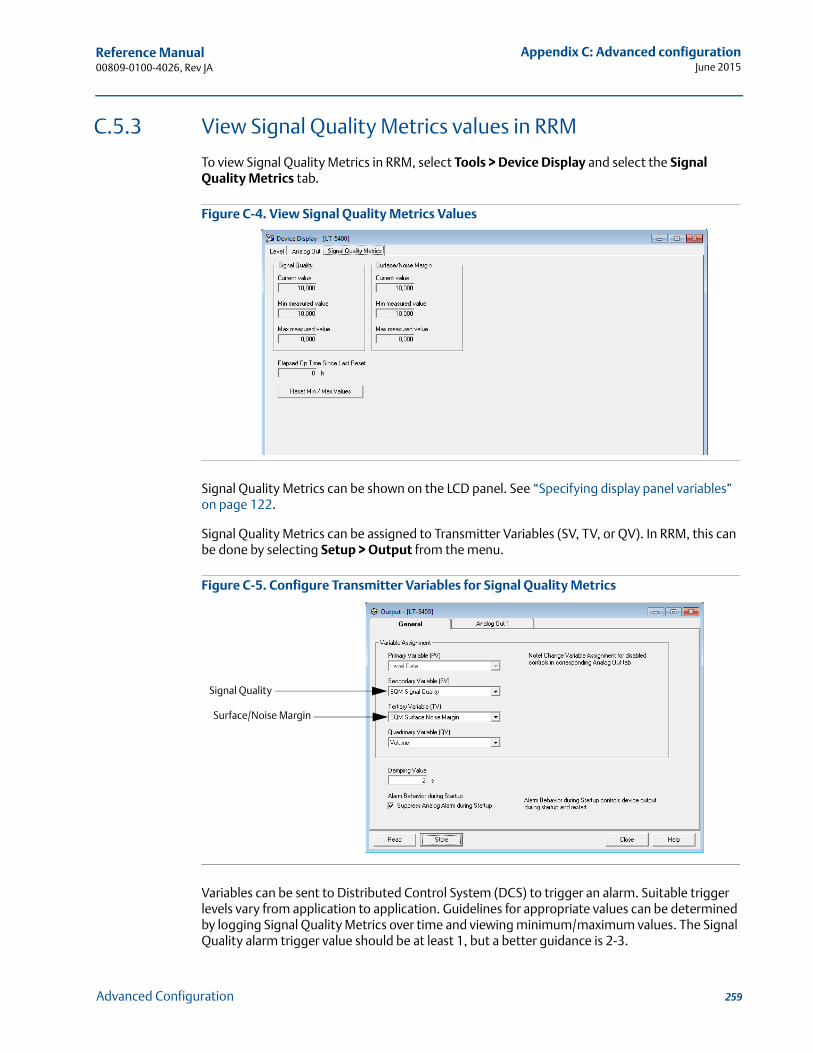
Reference Manual 00809-0100-4026, Rev JA
Appendix C: Advanced configurationJune 2015
C.5.3 View Signal Quality Metrics values in RRM
To view Signal Quality Metrics in RRM, select Tools > Device Display and select the Signal Quality Metrics tab.
Figure C-4. View Signal Quality Metrics Values
Signal Quality Metrics can be shown on the LCD panel. See “Specifying display panel variables” on page 122.
Signal Quality Metrics can be assigned to Transmitter Variables (SV, TV, or QV). In RRM, this can be done by selecting Setup > Output from the menu.
Figure C-5. Configure Transmitter Variables for Signal Quality Metrics
Variables can be sent to Distributed Control System (DCS) to trigger an alarm. Suitable trigger levels vary from application to application. Guidelines for appropriate values can be determined by logging Signal Quality Metrics over time and viewing minimum/maximum values. The Signal Quality alarm trigger value should be at least 1, but a better guidance is 2-3.
Signal Quality
Surface/Noise Margin
259Advanced Configuration

Reference Manual00809-0100-4026, Rev JA
Appendix C: Advanced configurationJune 2015
260 Advanced Configuration
Reference Manual 00809-0100-4026, Rev JA
Appendix D: Performing proof testJune 2015
Appendix D Performing Proof Test
Performing proof test . . . . . . . . . . . . . . . . . . . . . . . . . . . . . . . . . . . . . . . . . . . . . . . . . . . . . . . . page 261Field Communicator . . . . . . . . . . . . . . . . . . . . . . . . . . . . . . . . . . . . . . . . . . . . . . . . . . . . . . . . . page 261RRM . . . . . . . . . . . . . . . . . . . . . . . . . . . . . . . . . . . . . . . . . . . . . . . . . . . . . . . . . . . . . . . . . . . . . . . page 263AMS Suite . . . . . . . . . . . . . . . . . . . . . . . . . . . . . . . . . . . . . . . . . . . . . . . . . . . . . . . . . . . . . . . . . . page 265
D.1 Performing proof test
This test detects approximately 95 % of the possible Dangerously Undetected (DU) failures of the transmitter including the sensor element. Here is a description of how to perform the test using a Field Communicator, RRM, or AMS® Suite. Note that the transmitter is not safety-rated during proof tests. Alternative means should be used to ensure process safety during such activities.
Required tools: HART® host/communicator and a mA meter.
D.2 Field Communicator
Prior to this test, inspect the echo curve to ensure that no disturbing echoes affecting the measurement performance are present.
HART Sequence: [2, 6, 1]
1. Bypass the safety PLC or take other appropriate actions to avoid false trip.
2. Disable write protection if the function is enabled.
HART Sequence: [3, 2, 1, 2, 1]. Type the password.
3. Using loop test, enter the mA value representing the high alarm current. Verify that the analog output current is correct using the reference meter.This step tests for compliance voltage problems, such as low power supply voltage or increased wiring resistance.
HART Sequence: [2, 4, 1, 7]. Select 3 Other. Enter the analog output level representing the high alarm current. Press Enter and click OK.Verify that the analog output current is correct. Click Abort to end loop test.
4. Using loop test, enter the mA value representing the low alarm current. Verify that the analog output current is correct using the reference meter.This step tests for possible quiescent current related failures.
HART Sequence: [2, 4, 1, 7]. Select 3 Other. Enter the analog output level representing the low alarm current. Press Enter and click OK.Verify that the analog output current is correct. Click Abort to end loop test. Verify that the Current output is restored to the original mode.
261Performing Proof Test
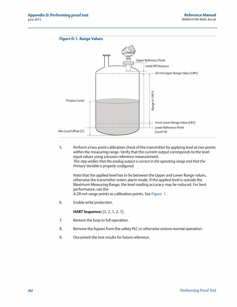
Reference Manual00809-0100-4026, Rev JA
Appendix D: Performing proof testJune 2015
Figure D-1. Range Values
5. Perform a two-point calibration check of the transmitter by applying level at two points within the measuring range. Verify that the current output corresponds to the level input values using a known reference measurement.This step verifies that the analog output is correct in the operating range and that the Primary Variable is properly configured.
Note that the applied level has to be between the Upper and Lower Range values, otherwise the transmitter enters alarm mode. If the applied level is outside the Maximum Measuring Range, the level reading accuracy may be reduced. For best performance, use the 4-20 mA range points as calibration points. See Figure 1.
6. Enable write protection.
HART Sequence: [3, 2, 1, 2, 1].
7. Restore the loop to full operation.
8. Remove the bypass from the safety PLC or otherwise restore normal operation.
9. Document the test results for future reference.
20 mA Upper Range Value (URV)
Product Level
4 mA Lower Range Value (LRV)
Rang
e 0-
100
%
Upper Reference Point
Min Level Offset (C)
Hold Off Distance
Lower Reference Point(Level=0)
262 Performing Proof Test
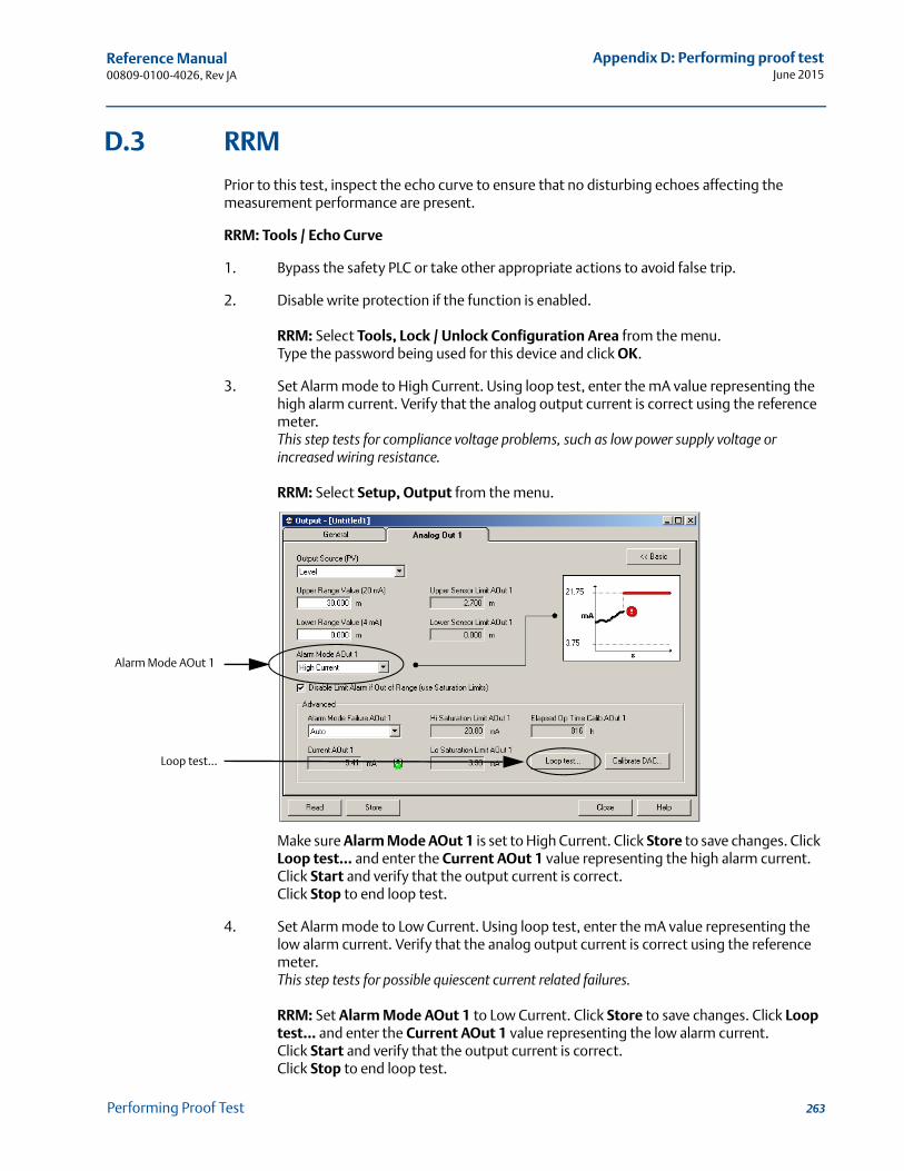
Reference Manual 00809-0100-4026, Rev JA
Appendix D: Performing proof testJune 2015
D.3 RRM
Prior to this test, inspect the echo curve to ensure that no disturbing echoes affecting the measurement performance are present.
RRM: Tools / Echo Curve
1. Bypass the safety PLC or take other appropriate actions to avoid false trip.
2. Disable write protection if the function is enabled.
RRM: Select Tools, Lock / Unlock Configuration Area from the menu.Type the password being used for this device and click OK.
3. Set Alarm mode to High Current. Using loop test, enter the mA value representing the high alarm current. Verify that the analog output current is correct using the reference meter.This step tests for compliance voltage problems, such as low power supply voltage or increased wiring resistance.
RRM: Select Setup, Output from the menu.
Make sure Alarm Mode AOut 1 is set to High Current. Click Store to save changes. Click Loop test... and enter the Current AOut 1 value representing the high alarm current.Click Start and verify that the output current is correct.Click Stop to end loop test.
4. Set Alarm mode to Low Current. Using loop test, enter the mA value representing the low alarm current. Verify that the analog output current is correct using the reference meter.This step tests for possible quiescent current related failures.
RRM: Set Alarm Mode AOut 1 to Low Current. Click Store to save changes. Click Loop test... and enter the Current AOut 1 value representing the low alarm current.Click Start and verify that the output current is correct.Click Stop to end loop test.
Alarm Mode AOut 1
Loop test...
263Performing Proof Test
Reference Manual00809-0100-4026, Rev JA
Appendix D: Performing proof testJune 2015
5. Restore the Alarm mode to the original mode used in the loop. Verify that the analog output current is correct.
RRM: Set Alarm Mode AOut 1 to original mode. Click Store to save changes.Verify that the output current is correct.
6. Perform a two-point calibration check of the transmitter by applying level at two points within the measuring range. Verify that the current output corresponds to the level input values using a known reference measurement.This step verifies that the analog output is correct in the operating range and that the Primary Variable is properly configured.
Note that the applied level has to be between the Upper and Lower Range values, otherwise the transmitter enters alarm mode. If the applied level is outside the Maximum Measuring Range, the level reading accuracy may be reduced. For best performance, use the 4-20 mA range points as calibration points. See Figure 1 on page 262.
7. Enable write protection.
RRM: Select Tools, Lock / Unlock Configuration Area from the menu.
8. Restore the loop to full operation.
9. Remove the bypass from the safety PLC or otherwise restore normal operation.
10. Document the test results for future reference.
264 Performing Proof Test
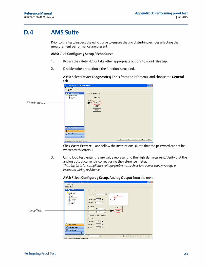
Reference Manual 00809-0100-4026, Rev JA
Appendix D: Performing proof testJune 2015
D.4 AMS Suite
Prior to this test, inspect the echo curve to ensure that no disturbing echoes affecting the measurement performance are present.
AMS: Click Configure / Setup / Echo Curve
1. Bypass the safety PLC or take other appropriate actions to avoid false trip.
2. Disable write protection if the function is enabled.
AMS: Select Device Diagnostics/ Tools from the left menu, and choose the General tab.
Click Write Protect... and follow the instructions. (Note that the password cannot be written with letters.)
3. Using loop test, enter the mA value representing the high alarm current. Verify that the analog output current is correct using the reference meter.This step tests for compliance voltage problems, such as low power supply voltage or increased wiring resistance.
AMS: Select Configure / Setup, Analog Output from the menu.
Write Protect...
Loop Test...
265Performing Proof Test
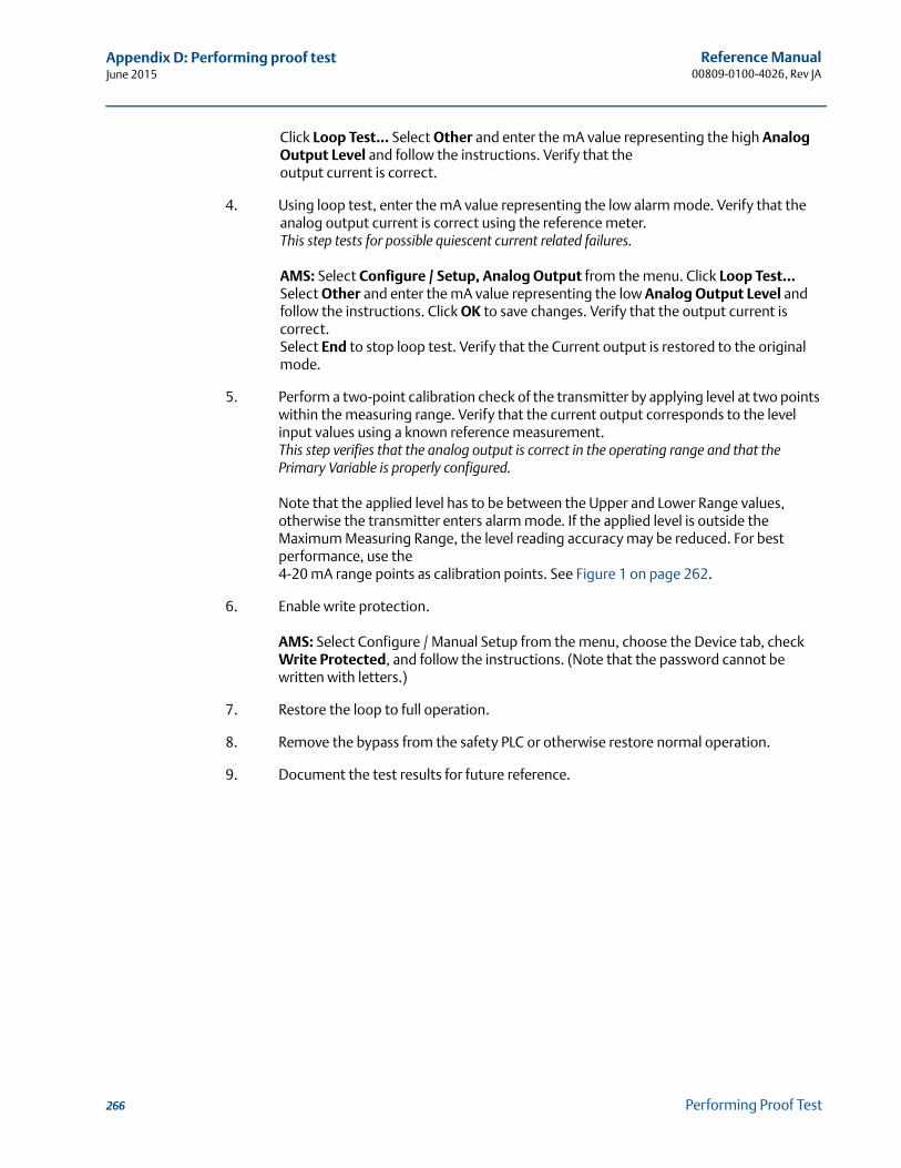
Reference Manual00809-0100-4026, Rev JA
Appendix D: Performing proof testJune 2015
Click Loop Test... Select Other and enter the mA value representing the high Analog Output Level and follow the instructions. Verify that the output current is correct.
4. Using loop test, enter the mA value representing the low alarm mode. Verify that the analog output current is correct using the reference meter.This step tests for possible quiescent current related failures.
AMS: Select Configure / Setup, Analog Output from the menu. Click Loop Test... Select Other and enter the mA value representing the low Analog Output Level and follow the instructions. Click OK to save changes. Verify that the output current is correct. Select End to stop loop test. Verify that the Current output is restored to the original mode.
5. Perform a two-point calibration check of the transmitter by applying level at two points within the measuring range. Verify that the current output corresponds to the level input values using a known reference measurement.This step verifies that the analog output is correct in the operating range and that the Primary Variable is properly configured.
Note that the applied level has to be between the Upper and Lower Range values, otherwise the transmitter enters alarm mode. If the applied level is outside the Maximum Measuring Range, the level reading accuracy may be reduced. For best performance, use the 4-20 mA range points as calibration points. See Figure 1 on page 262.
6. Enable write protection.
AMS: Select Configure / Manual Setup from the menu, choose the Device tab, check Write Protected, and follow the instructions. (Note that the password cannot be written with letters.)
7. Restore the loop to full operation.
8. Remove the bypass from the safety PLC or otherwise restore normal operation.
9. Document the test results for future reference.
266 Performing Proof Test
Reference Manual 00809-0100-4026, Rev JA
Appendix E: Level transducer blockJune 2015
Appendix E Level Transducer Block
Overview . . . . . . . . . . . . . . . . . . . . . . . . . . . . . . . . . . . . . . . . . . . . . . . . . . . . . . . . . . . . . . . . . . . page 267Parameters and descriptions . . . . . . . . . . . . . . . . . . . . . . . . . . . . . . . . . . . . . . . . . . . . . . . . . . page 268Supported units . . . . . . . . . . . . . . . . . . . . . . . . . . . . . . . . . . . . . . . . . . . . . . . . . . . . . . . . . . . . . page 273Diagnostics device errors . . . . . . . . . . . . . . . . . . . . . . . . . . . . . . . . . . . . . . . . . . . . . . . . . . . . . page 274
E.1 Overview
This section contains information on the Rosemount 5400 Series Transducer Block (TB). Descriptions of all Transducer Block parameters, errors, and diagnostics are listed.
E.1.1 Definition
The transducer block contains the actual measurement data, including a level and distance reading. Channels 1–6 are assigned to these measurements. The transducer block includes information about sensor type, engineering units, and all parameters needed to configure the radar gauge.
E.1.2 Channel definitions
Each input has an assigned channel which can be linked to the AI block. The channels for the Rosemount 5400 Series are the following:
Table E-1. Channel Assignments
Channel name Channel number Process variable
Level 1 RADAR_LEVELUllage 2 RADAR_ULLAGELevel Rate 3 RADAR_LEVELRATESignal Strength 4 RADAR_LEVEL_SIGNAL_STRENGTHVolume 5 RADAR_VOLUMEInternal Temperature 6 RADAR_INTERNAL_TEMPERATURE
267Level Transducer Block
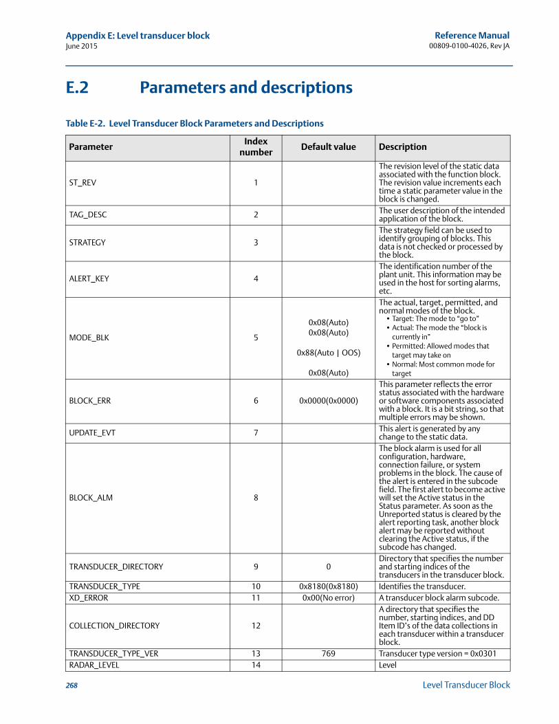
Reference Manual00809-0100-4026, Rev JA
Appendix E: Level transducer blockJune 2015
E.2 Parameters and descriptions
Table E-2. Level Transducer Block Parameters and Descriptions
ParameterIndex
numberDefault value Description
ST_REV 1
The revision level of the static data associated with the function block. The revision value increments each time a static parameter value in the block is changed.
TAG_DESC 2 The user description of the intended application of the block.
STRATEGY 3
The strategy field can be used to identify grouping of blocks. This data is not checked or processed by the block.
ALERT_KEY 4
The identification number of the plant unit. This information may be used in the host for sorting alarms, etc.
MODE_BLK 5
0x08(Auto)0x08(Auto)
0x88(Auto | OOS)
0x08(Auto)
The actual, target, permitted, and normal modes of the block.
• Target: The mode to “go to”• Actual: The mode the “block is
currently in”• Permitted: Allowed modes that
target may take on• Normal: Most common mode for
target
BLOCK_ERR 6 0x0000(0x0000)
This parameter reflects the error status associated with the hardware or software components associated with a block. It is a bit string, so that multiple errors may be shown.
UPDATE_EVT 7 This alert is generated by any change to the static data.
BLOCK_ALM 8
The block alarm is used for all configuration, hardware, connection failure, or system problems in the block. The cause of the alert is entered in the subcode field. The first alert to become active will set the Active status in the Status parameter. As soon as the Unreported status is cleared by the alert reporting task, another block alert may be reported without clearing the Active status, if the subcode has changed.
TRANSDUCER_DIRECTORY 9 0Directory that specifies the number and starting indices of the transducers in the transducer block.
TRANSDUCER_TYPE 10 0x8180(0x8180) Identifies the transducer.XD_ERROR 11 0x00(No error) A transducer block alarm subcode.
COLLECTION_DIRECTORY 12
A directory that specifies the number, starting indices, and DD Item ID’s of the data collections in each transducer within a transducer block.
TRANSDUCER_TYPE_VER 13 769 Transducer type version = 0x0301RADAR_LEVEL 14 Level
268 Level Transducer Block
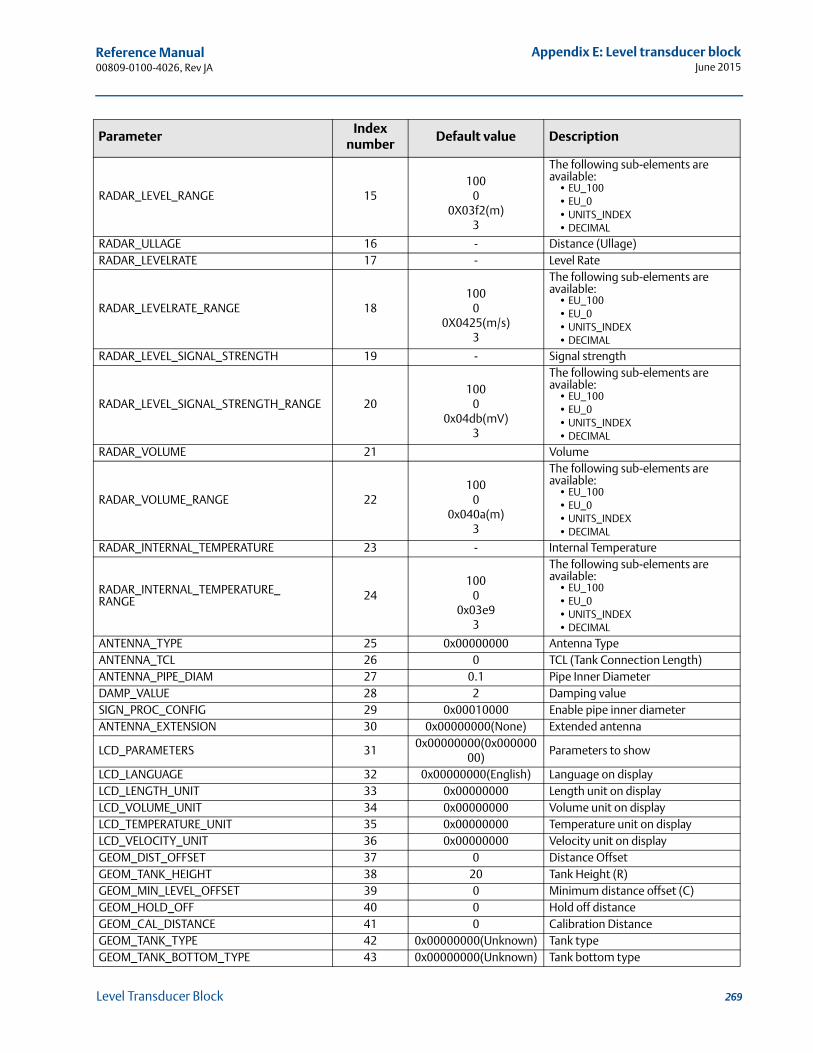
Reference Manual 00809-0100-4026, Rev JA
Appendix E: Level transducer blockJune 2015
RADAR_LEVEL_RANGE 15100
00X03f2(m)
3
The following sub-elements are available:
• EU_100• EU_0• UNITS_INDEX• DECIMAL
RADAR_ULLAGE 16 - Distance (Ullage)RADAR_LEVELRATE 17 - Level Rate
RADAR_LEVELRATE_RANGE 18100
00X0425(m/s)
3
The following sub-elements are available:
• EU_100• EU_0• UNITS_INDEX• DECIMAL
RADAR_LEVEL_SIGNAL_STRENGTH 19 - Signal strength
RADAR_LEVEL_SIGNAL_STRENGTH_RANGE 20100
00x04db(mV)
3
The following sub-elements are available:
• EU_100• EU_0• UNITS_INDEX• DECIMAL
RADAR_VOLUME 21 Volume
RADAR_VOLUME_RANGE 22100
00x040a(m)
3
The following sub-elements are available:
• EU_100• EU_0• UNITS_INDEX• DECIMAL
RADAR_INTERNAL_TEMPERATURE 23 - Internal Temperature
RADAR_INTERNAL_TEMPERATURE_RANGE 24
1000
0x03e93
The following sub-elements are available:
• EU_100• EU_0• UNITS_INDEX• DECIMAL
ANTENNA_TYPE 25 0x00000000 Antenna TypeANTENNA_TCL 26 0 TCL (Tank Connection Length)ANTENNA_PIPE_DIAM 27 0.1 Pipe Inner DiameterDAMP_VALUE 28 2 Damping valueSIGN_PROC_CONFIG 29 0x00010000 Enable pipe inner diameterANTENNA_EXTENSION 30 0x00000000(None) Extended antenna
LCD_PARAMETERS 310x00000000(0x000000
00)Parameters to show
LCD_LANGUAGE 32 0x00000000(English) Language on displayLCD_LENGTH_UNIT 33 0x00000000 Length unit on displayLCD_VOLUME_UNIT 34 0x00000000 Volume unit on displayLCD_TEMPERATURE_UNIT 35 0x00000000 Temperature unit on displayLCD_VELOCITY_UNIT 36 0x00000000 Velocity unit on displayGEOM_DIST_OFFSET 37 0 Distance OffsetGEOM_TANK_HEIGHT 38 20 Tank Height (R)GEOM_MIN_LEVEL_OFFSET 39 0 Minimum distance offset (C)GEOM_HOLD_OFF 40 0 Hold off distanceGEOM_CAL_DISTANCE 41 0 Calibration DistanceGEOM_TANK_TYPE 42 0x00000000(Unknown) Tank type GEOM_TANK_BOTTOM_TYPE 43 0x00000000(Unknown) Tank bottom type
ParameterIndex
numberDefault value Description
269Level Transducer Block
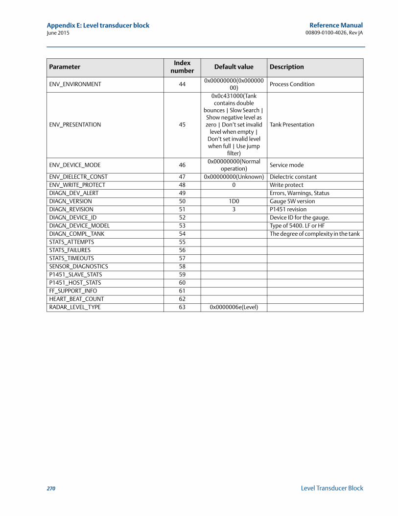
Reference Manual00809-0100-4026, Rev JA
Appendix E: Level transducer blockJune 2015
ENV_ENVIRONMENT 440x00000000(0x000000
00)Process Condition
ENV_PRESENTATION 45
0x0c431000(Tank contains double
bounces | Slow Search | Show negative level as zero | Don’t set invalid
level when empty | Don’t set invalid level when full | Use jump
filter)
Tank Presentation
ENV_DEVICE_MODE 460x00000000(Normal
operation)Service mode
ENV_DIELECTR_CONST 47 0x00000000(Unknown) Dielectric constantENV_WRITE_PROTECT 48 0 Write protectDIAGN_DEV_ALERT 49 Errors, Warnings, StatusDIAGN_VERSION 50 1D0 Gauge SW versionDIAGN_REVISION 51 3 P1451 revisionDIAGN_DEVICE_ID 52 Device ID for the gauge.DIAGN_DEVICE_MODEL 53 Type of 5400. LF or HFDIAGN_COMPL_TANK 54 The degree of complexity in the tank STATS_ATTEMPTS 55STATS_FAILURES 56STATS_TIMEOUTS 57SENSOR_DIAGNOSTICS 58P1451_SLAVE_STATS 59P1451_HOST_STATS 60FF_SUPPORT_INFO 61HEART_BEAT_COUNT 62RADAR_LEVEL_TYPE 63 0x0000006e(Level)
ParameterIndex
numberDefault value Description
270 Level Transducer Block
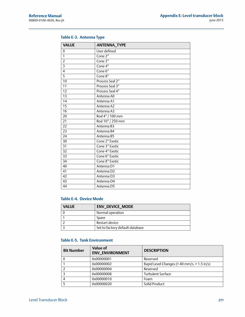
Reference Manual 00809-0100-4026, Rev JA
Appendix E: Level transducer blockJune 2015
Table E-3. Antenna Type
Table E-4. Device Mode
Table E-5. Tank Environment
VALUE ANTENNA_TYPE
0 User defined1 Cone 2”2 Cone 3”3 Cone 4”4 Cone 6”5 Cone 8”10 Process Seal 2”11 Process Seal 3”12 Process Seal 4”13 Antenna A014 Antenna A115 Antenna A216 Antenna A320 Rod 4” / 100 mm21 Rod 10” / 250 mm22 Antenna B323 Antenna B424 Antenna B530 Cone 2” Exotic31 Cone 3” Exotic32 Cone 4” Exotic33 Cone 6” Exotic34 Cone 8” Exotic40 Antenna D141 Antenna D242 Antenna D343 Antenna D444 Antenna D5
VALUE ENV_DEVICE_MODE
0 Normal operation1 Spare2 Restart device3 Set to factory default database
Bit NumberValue of ENV_ENVIRONMENT
DESCRIPTION
0 0x00000001 Reserved1 0x00000002 Rapid Level Changes (> 40 mm/s, > 1.5 in/s)2 0x00000004 Reserved3 0x00000008 Turbulent Surface4 0x00000010 Foam5 0x00000020 Solid Product
271Level Transducer Block
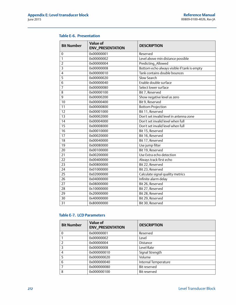
Reference Manual00809-0100-4026, Rev JA
Appendix E: Level transducer blockJune 2015
Table E-6. Presentation
Table E-7. LCD Parameters
Bit NumberValue of ENV_PRESENTATION
DESCRIPTION
0 0x00000001 Reserved1 0x00000002 Level above min distance possible2 0x00000004 Predicting_Allowed3 0x00000008 Bottom echo always visible if tank is empty4 0x00000010 Tank contains double bounces5 0x00000020 Slow Search6 0x00000040 Enable double surface7 0x00000080 Select lower surface8 0x00000100 Bit 7, Reserved9 0x00000200 Show negative level as zero10 0x00000400 Bit 9, Reserved11 0x00000800 Bottom Projection12 0x00001000 Bit 11, Reserved13 0x00002000 Don't set invalid level in antenna zone14 0x00004000 Don't set invalid level when full15 0x00008000 Don't set invalid level when full16 0x00010000 Bit 15, Reserved17 0x00020000 Bit 16, Reserved18 0x00040000 Bit 17, Reserved19 0x00080000 Use jump filter20 0x00100000 Bit 19, Reserved21 0x00200000 Use Extra echo detection22 0x00400000 Always track first echo23 0x00800000 Bit 22, Reserved24 0x01000000 Bit 23, Reserved25 0x02000000 Calculate signal quality metrics26 0x04000000 Infinite alarm delay27 0x08000000 Bit 26, Reserved28 0x10000000 Bit 27, Reserved29 0x20000000 Bit 28, Reserved30 0x40000000 Bit 29, Reserved31 0x80000000 Bit 30, Reserved
Bit NumberValue of ENV_PRESENTATION
DESCRIPTION
0 0x00000001 Reserved1 0x00000002 Level2 0x00000004 Distance3 0x00000008 Level Rate4 0x000000010 Signal Strength5 0x000000020 Volume6 0x000000040 Internal Temperature7 0x000000080 Bit reserved8 0x000000100 Bit reserved
272 Level Transducer Block
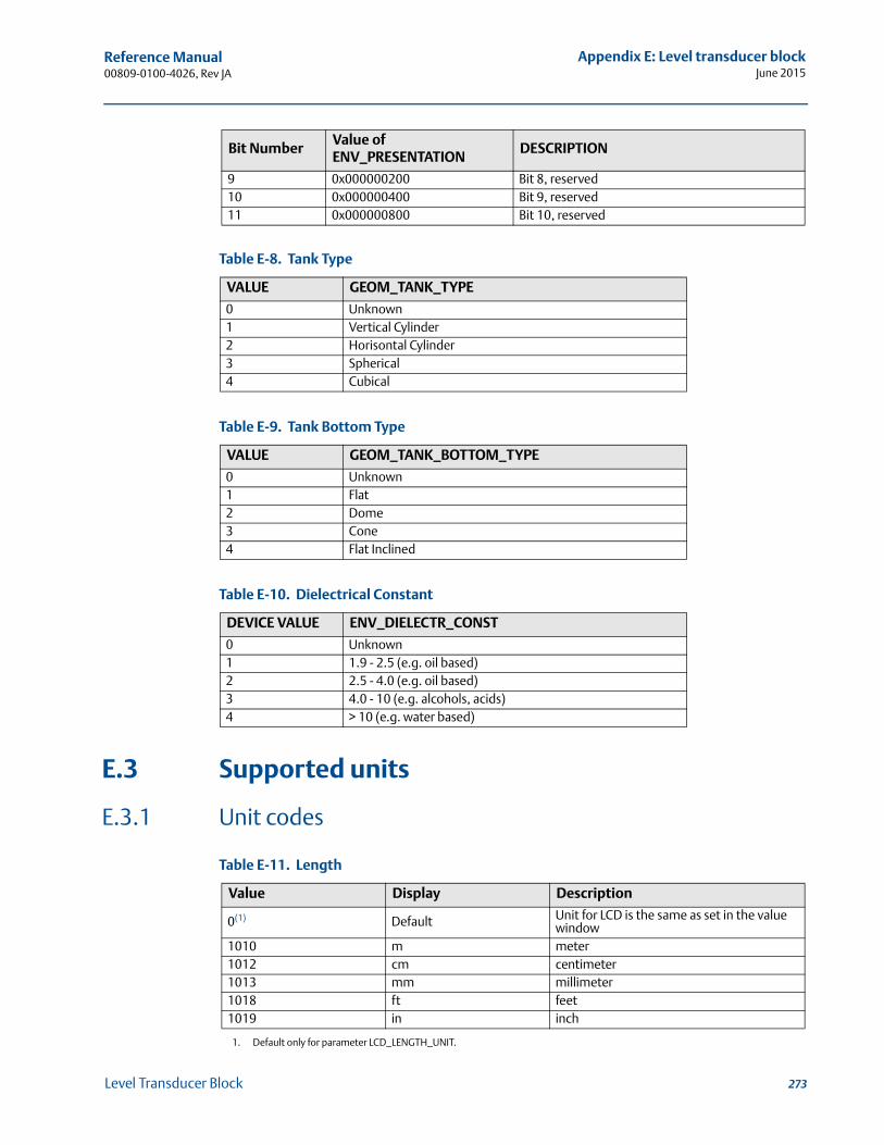
Reference Manual 00809-0100-4026, Rev JA
Appendix E: Level transducer blockJune 2015
Table E-8. Tank Type
Table E-9. Tank Bottom Type
Table E-10. Dielectrical Constant
E.3 Supported units
E.3.1 Unit codes
Table E-11. Length
9 0x000000200 Bit 8, reserved10 0x000000400 Bit 9, reserved11 0x000000800 Bit 10, reserved
VALUE GEOM_TANK_TYPE
0 Unknown1 Vertical Cylinder2 Horisontal Cylinder3 Spherical4 Cubical
VALUE GEOM_TANK_BOTTOM_TYPE
0 Unknown1 Flat2 Dome3 Cone4 Flat Inclined
DEVICE VALUE ENV_DIELECTR_CONST
0 Unknown1 1.9 - 2.5 (e.g. oil based)2 2.5 - 4.0 (e.g. oil based)3 4.0 - 10 (e.g. alcohols, acids)4 > 10 (e.g. water based)
Value Display Description
0(1)
1. Default only for parameter LCD_LENGTH_UNIT.
Default Unit for LCD is the same as set in the value window
1010 m meter1012 cm centimeter1013 mm millimeter1018 ft feet1019 in inch
Bit NumberValue of ENV_PRESENTATION
DESCRIPTION
273Level Transducer Block
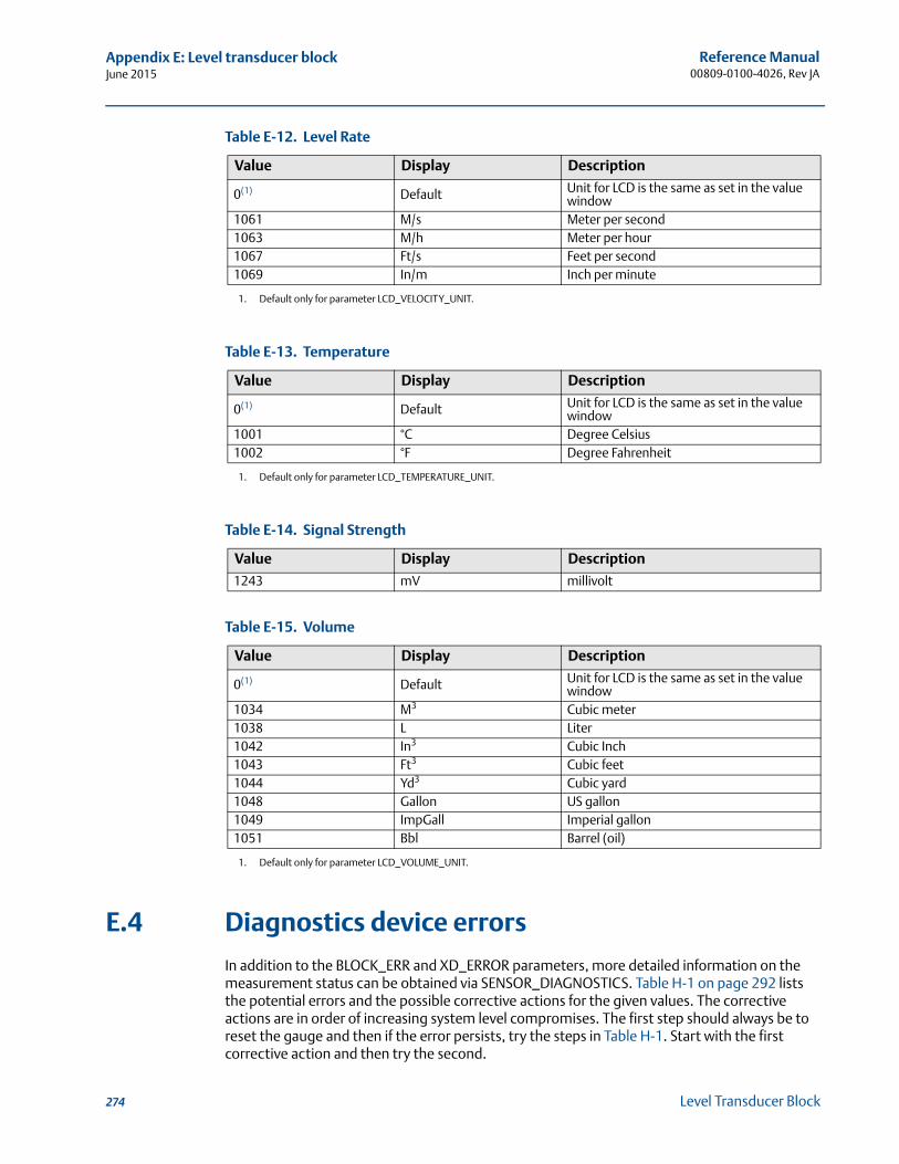
Reference Manual00809-0100-4026, Rev JA
Appendix E: Level transducer blockJune 2015
Table E-12. Level Rate
Table E-13. Temperature
Table E-14. Signal Strength
Table E-15. Volume
E.4 Diagnostics device errors
In addition to the BLOCK_ERR and XD_ERROR parameters, more detailed information on the measurement status can be obtained via SENSOR_DIAGNOSTICS. Table H-1 on page 292 lists the potential errors and the possible corrective actions for the given values. The corrective actions are in order of increasing system level compromises. The first step should always be to reset the gauge and then if the error persists, try the steps in Table H-1. Start with the first corrective action and then try the second.
Value Display Description
0(1)
1. Default only for parameter LCD_VELOCITY_UNIT.
Default Unit for LCD is the same as set in the value window
1061 M/s Meter per second1063 M/h Meter per hour1067 Ft/s Feet per second1069 In/m Inch per minute
Value Display Description
0(1)
1. Default only for parameter LCD_TEMPERATURE_UNIT.
Default Unit for LCD is the same as set in the value window
1001 °C Degree Celsius1002 °F Degree Fahrenheit
Value Display Description
1243 mV millivolt
Value Display Description
0(1)
1. Default only for parameter LCD_VOLUME_UNIT.
Default Unit for LCD is the same as set in the value window
1034 M3 Cubic meter1038 L Liter1042 In3 Cubic Inch1043 Ft3 Cubic feet1044 Yd3 Cubic yard1048 Gallon US gallon1049 ImpGall Imperial gallon1051 Bbl Barrel (oil)
274 Level Transducer Block
Reference Manual 00809-0100-4026, Rev JA
Appendix F: Register transducer blockJune 2015
Appendix F Register Transducer Block
Overview . . . . . . . . . . . . . . . . . . . . . . . . . . . . . . . . . . . . . . . . . . . . . . . . . . . . . . . . . . . . . . . . . . . page 275
F.1 Overview
The Register Transducer Block allows access to Database registers and Input registers of the Rosemount 5400 transmitter. This makes it possible to read a selected set of registers directly by accessing the memory location.
The Register Transducer Block is only available with advanced service.
Since this Register Transducer Block allows access to most registers in the transmitter, which includes the registers set by the Methods and Configuration screens, in the Level Transducer Block (see Appendix E: Level Transducer Block) it should be handled with care and ONLY to be changed by trained and certified service personnel, or as guided by Emerson Process Management, Rosemount Business Unit support personnel.
275Register Transducer Block
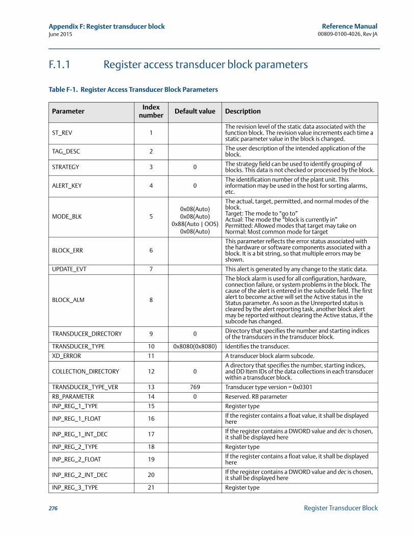
Reference Manual00809-0100-4026, Rev JA
Appendix F: Register transducer blockJune 2015
F.1.1 Register access transducer block parameters
Table F-1. Register Access Transducer Block Parameters
ParameterIndex
numberDefault value Description
ST_REV 1The revision level of the static data associated with the function block. The revision value increments each time a static parameter value in the block is changed.
TAG_DESC 2 The user description of the intended application of the block.
STRATEGY 3 0 The strategy field can be used to identify grouping of blocks. This data is not checked or processed by the block.
ALERT_KEY 4 0The identification number of the plant unit. This information may be used in the host for sorting alarms, etc.
MODE_BLK 50x08(Auto)0x08(Auto)
0x88(Auto | OOS)0x08(Auto)
The actual, target, permitted, and normal modes of the block.Target: The mode to “go to”Actual: The mode the “block is currently in”Permitted: Allowed modes that target may take onNormal: Most common mode for target
BLOCK_ERR 6
This parameter reflects the error status associated with the hardware or software components associated with a block. It is a bit string, so that multiple errors may be shown.
UPDATE_EVT 7 This alert is generated by any change to the static data.
BLOCK_ALM 8
The block alarm is used for all configuration, hardware, connection failure, or system problems in the block. The cause of the alert is entered in the subcode field. The first alert to become active will set the Active status in the Status parameter. As soon as the Unreported status is cleared by the alert reporting task, another block alert may be reported without clearing the Active status, if the subcode has changed.
TRANSDUCER_DIRECTORY 9 0 Directory that specifies the number and starting indices of the transducers in the transducer block.
TRANSDUCER_TYPE 10 0x8080(0x8080) Identifies the transducer.
XD_ERROR 11 A transducer block alarm subcode.
COLLECTION_DIRECTORY 12 0A directory that specifies the number, starting indices, and DD Item IDs of the data collections in each transducer within a transducer block.
TRANSDUCER_TYPE_VER 13 769 Transducer type version = 0x0301
RB_PARAMETER 14 0 Reserved. RB parameter
INP_REG_1_TYPE 15 Register type
INP_REG_1_FLOAT 16 If the register contains a float value, it shall be displayed here
INP_REG_1_INT_DEC 17 If the register contains a DWORD value and dec is chosen,it shall be displayed here
INP_REG_2_TYPE 18 Register type
INP_REG_2_FLOAT 19 If the register contains a float value, it shall be displayed here
INP_REG_2_INT_DEC 20 If the register contains a DWORD value and dec is chosen,it shall be displayed here
INP_REG_3_TYPE 21 Register type
276 Register Transducer Block
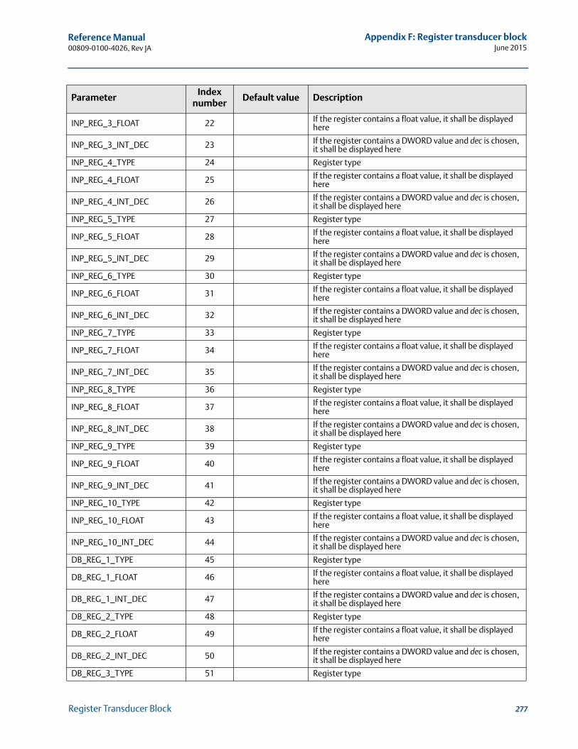
Reference Manual 00809-0100-4026, Rev JA
Appendix F: Register transducer blockJune 2015
INP_REG_3_FLOAT 22 If the register contains a float value, it shall be displayed here
INP_REG_3_INT_DEC 23 If the register contains a DWORD value and dec is chosen,it shall be displayed here
INP_REG_4_TYPE 24 Register type
INP_REG_4_FLOAT 25 If the register contains a float value, it shall be displayed here
INP_REG_4_INT_DEC 26 If the register contains a DWORD value and dec is chosen,it shall be displayed here
INP_REG_5_TYPE 27 Register type
INP_REG_5_FLOAT 28 If the register contains a float value, it shall be displayed here
INP_REG_5_INT_DEC 29 If the register contains a DWORD value and dec is chosen,it shall be displayed here
INP_REG_6_TYPE 30 Register type
INP_REG_6_FLOAT 31 If the register contains a float value, it shall be displayed here
INP_REG_6_INT_DEC 32 If the register contains a DWORD value and dec is chosen,it shall be displayed here
INP_REG_7_TYPE 33 Register type
INP_REG_7_FLOAT 34 If the register contains a float value, it shall be displayed here
INP_REG_7_INT_DEC 35 If the register contains a DWORD value and dec is chosen,it shall be displayed here
INP_REG_8_TYPE 36 Register type
INP_REG_8_FLOAT 37 If the register contains a float value, it shall be displayed here
INP_REG_8_INT_DEC 38 If the register contains a DWORD value and dec is chosen,it shall be displayed here
INP_REG_9_TYPE 39 Register type
INP_REG_9_FLOAT 40 If the register contains a float value, it shall be displayed here
INP_REG_9_INT_DEC 41 If the register contains a DWORD value and dec is chosen,it shall be displayed here
INP_REG_10_TYPE 42 Register type
INP_REG_10_FLOAT 43 If the register contains a float value, it shall be displayed here
INP_REG_10_INT_DEC 44 If the register contains a DWORD value and dec is chosen,it shall be displayed here
DB_REG_1_TYPE 45 Register type
DB_REG_1_FLOAT 46 If the register contains a float value, it shall be displayed here
DB_REG_1_INT_DEC 47 If the register contains a DWORD value and dec is chosen, it shall be displayed here
DB_REG_2_TYPE 48 Register type
DB_REG_2_FLOAT 49 If the register contains a float value, it shall be displayed here
DB_REG_2_INT_DEC 50 If the register contains a DWORD value and dec is chosen, it shall be displayed here
DB_REG_3_TYPE 51 Register type
ParameterIndex
numberDefault value Description
277Register Transducer Block
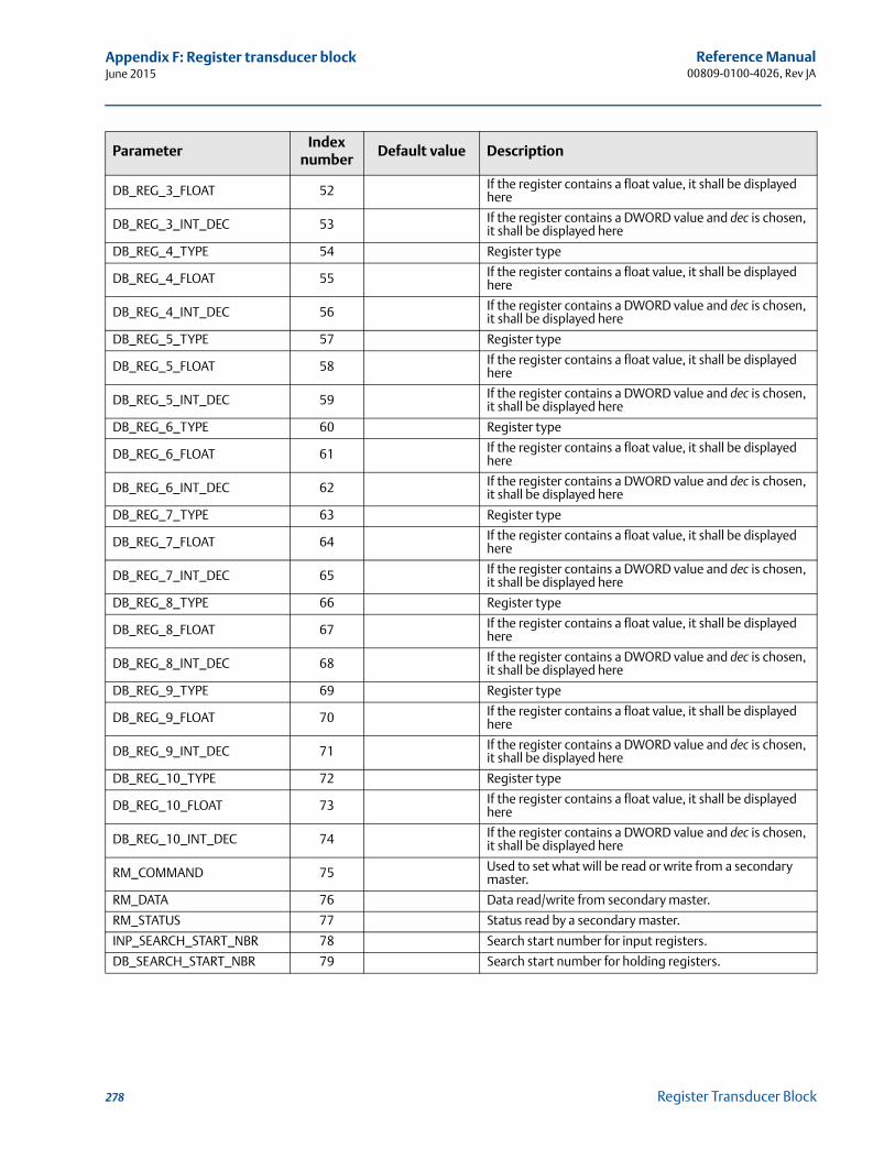
Reference Manual00809-0100-4026, Rev JA
Appendix F: Register transducer blockJune 2015
DB_REG_3_FLOAT 52 If the register contains a float value, it shall be displayed here
DB_REG_3_INT_DEC 53 If the register contains a DWORD value and dec is chosen, it shall be displayed here
DB_REG_4_TYPE 54 Register type
DB_REG_4_FLOAT 55 If the register contains a float value, it shall be displayed here
DB_REG_4_INT_DEC 56 If the register contains a DWORD value and dec is chosen, it shall be displayed here
DB_REG_5_TYPE 57 Register type
DB_REG_5_FLOAT 58 If the register contains a float value, it shall be displayed here
DB_REG_5_INT_DEC 59 If the register contains a DWORD value and dec is chosen, it shall be displayed here
DB_REG_6_TYPE 60 Register type
DB_REG_6_FLOAT 61 If the register contains a float value, it shall be displayed here
DB_REG_6_INT_DEC 62 If the register contains a DWORD value and dec is chosen, it shall be displayed here
DB_REG_7_TYPE 63 Register type
DB_REG_7_FLOAT 64 If the register contains a float value, it shall be displayed here
DB_REG_7_INT_DEC 65 If the register contains a DWORD value and dec is chosen, it shall be displayed here
DB_REG_8_TYPE 66 Register type
DB_REG_8_FLOAT 67 If the register contains a float value, it shall be displayed here
DB_REG_8_INT_DEC 68 If the register contains a DWORD value and dec is chosen, it shall be displayed here
DB_REG_9_TYPE 69 Register type
DB_REG_9_FLOAT 70 If the register contains a float value, it shall be displayed here
DB_REG_9_INT_DEC 71 If the register contains a DWORD value and dec is chosen, it shall be displayed here
DB_REG_10_TYPE 72 Register type
DB_REG_10_FLOAT 73 If the register contains a float value, it shall be displayed here
DB_REG_10_INT_DEC 74 If the register contains a DWORD value and dec is chosen, it shall be displayed here
RM_COMMAND 75 Used to set what will be read or write from a secondary master.
RM_DATA 76 Data read/write from secondary master.
RM_STATUS 77 Status read by a secondary master.
INP_SEARCH_START_NBR 78 Search start number for input registers.
DB_SEARCH_START_NBR 79 Search start number for holding registers.
ParameterIndex
numberDefault value Description
278 Register Transducer Block
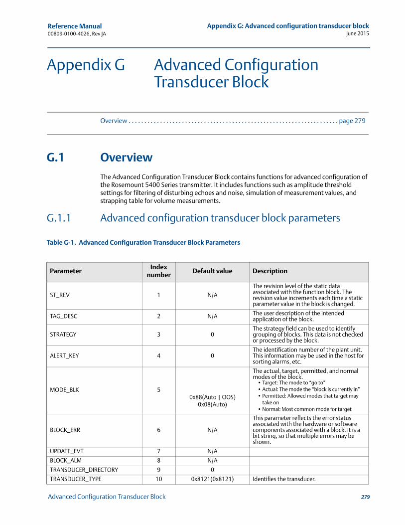
Reference Manual 00809-0100-4026, Rev JA
Appendix G: Advanced configuration transducer blockJune 2015
Appendix G Advanced Configuration Transducer Block
Overview . . . . . . . . . . . . . . . . . . . . . . . . . . . . . . . . . . . . . . . . . . . . . . . . . . . . . . . . . . . . . . . . . . . page 279
G.1 Overview
The Advanced Configuration Transducer Block contains functions for advanced configuration of the Rosemount 5400 Series transmitter. It includes functions such as amplitude threshold settings for filtering of disturbing echoes and noise, simulation of measurement values, and strapping table for volume measurements.
G.1.1 Advanced configuration transducer block parameters
Table G-1. Advanced Configuration Transducer Block Parameters
ParameterIndex
numberDefault value Description
ST_REV 1 N/A
The revision level of the static data associated with the function block. The revision value increments each time a static parameter value in the block is changed.
TAG_DESC 2 N/A The user description of the intended application of the block.
STRATEGY 3 0The strategy field can be used to identify grouping of blocks. This data is not checked or processed by the block.
ALERT_KEY 4 0The identification number of the plant unit. This information may be used in the host for sorting alarms, etc.
MODE_BLK 50x88(Auto | OOS)
0x08(Auto)
The actual, target, permitted, and normal modes of the block.
• Target: The mode to “go to”• Actual: The mode the “block is currently in”• Permitted: Allowed modes that target may
take on• Normal: Most common mode for target
BLOCK_ERR 6 N/A
This parameter reflects the error status associated with the hardware or software components associated with a block. It is a bit string, so that multiple errors may be shown.
UPDATE_EVT 7 N/A
BLOCK_ALM 8 N/A
TRANSDUCER_DIRECTORY 9 0
TRANSDUCER_TYPE 10 0x8121(0x8121) Identifies the transducer.
279Advanced Configuration Transducer Block
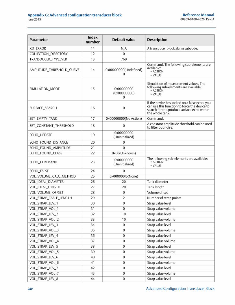
Reference Manual00809-0100-4026, Rev JA
Appendix G: Advanced configuration transducer blockJune 2015
XD_ERROR 11 N/A A transducer block alarm subcode.
COLLECTION_DIRECTORY 12 0
TRANSDUCER_TYPE_VER 13 769
AMPLITUDE_THRESHOLD_CURVE 14 0x00000000(Undefined)0
Command. The following sub-elements are available:
• ACTION• VALUE
SIMULATION_MODE 15 0x00000000(0x00000000)
0
Simulation of measurement values. The following sub-elements are available:
• ACTION• VALUE
SURFACE_SEARCH 16 0
If the device has locked on a false echo, you can use this function to force the device to search for the product surface echo within the whole tank.
SET_EMPTY_TANK 17 0x00000000(No Action) Command.
SET_CONSTANT_THRESHOLD 18 0 A constant amplitude threshold can be used to filter out noise.
ECHO_UPDATE 190x00000000
(Uninitialized)
ECHO_FOUND_DISTANCE 20 0
ECHO_FOUND_AMPLITUDE 21 0
ECHO_FOUND_CLASS 22 0x00(Unknown)
ECHO_COMMAND 230x00000000
(Uninitialized)
The following sub-elements are available:• ACTION• VALUE
ECHO_FALSE 24 0
VOL_VOLUME_CALC_METHOD 25 0x000000fb(None)
VOL_IDEAL_DIAMETER 26 20 Tank diameter
VOL_IDEAL_LENGTH 27 20 Tank length
VOL_VOLUME_OFFSET 28 0 Volume offset
VOL_STRAP_TABLE_LENGTH 29 2 Number of strap points
VOL_STRAP_LEV_1 30 0 Strap value level
VOL_STRAP_VOL_1 31 0 Strap value volume
VOL_STRAP_LEV_2 32 10 Strap value level
VOL_STRAP_VOL_2 33 10 Strap value volume
VOL_STRAP_LEV_3 34 0 Strap value level
VOL_STRAP_VOL_3 35 0 Strap value volume
VOL_STRAP_LEV_4 36 0 Strap value level
VOL_STRAP_VOL_4 37 0 Strap value volume
VOL_STRAP_LEV_5 38 0 Strap value level
VOL_STRAP_VOL_5 39 0 Strap value volume
VOL_STRAP_LEV_6 40 0 Strap value level
VOL_STRAP_VOL_6 41 0 Strap value volume
VOL_STRAP_LEV_7 42 0 Strap value level
VOL_STRAP_VOL_7 43 0 Strap value volume
VOL_STRAP_LEV_8 44 0 Strap value level
ParameterIndex
numberDefault value Description
280 Advanced Configuration Transducer Block
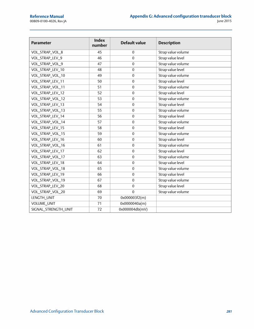
Reference Manual 00809-0100-4026, Rev JA
Appendix G: Advanced configuration transducer blockJune 2015
VOL_STRAP_VOL_8 45 0 Strap value volume
VOL_STRAP_LEV_9 46 0 Strap value level
VOL_STRAP_VOL_9 47 0 Strap value volume
VOL_STRAP_LEV_10 48 0 Strap value level
VOL_STRAP_VOL_10 49 0 Strap value volume
VOL_STRAP_LEV_11 50 0 Strap value level
VOL_STRAP_VOL_11 51 0 Strap value volume
VOL_STRAP_LEV_12 52 0 Strap value level
VOL_STRAP_VOL_12 53 0 Strap value volume
VOL_STRAP_LEV_13 54 0 Strap value level
VOL_STRAP_VOL_13 55 0 Strap value volume
VOL_STRAP_LEV_14 56 0 Strap value level
VOL_STRAP_VOL_14 57 0 Strap value volume
VOL_STRAP_LEV_15 58 0 Strap value level
VOL_STRAP_VOL_15 59 0 Strap value volume
VOL_STRAP_LEV_16 60 0 Strap value level
VOL_STRAP_VOL_16 61 0 Strap value volume
VOL_STRAP_LEV_17 62 0 Strap value level
VOL_STRAP_VOL_17 63 0 Strap value volume
VOL_STRAP_LEV_18 64 0 Strap value level
VOL_STRAP_VOL_18 65 0 Strap value volume
VOL_STRAP_LEV_19 66 0 Strap value level
VOL_STRAP_VOL_19 67 0 Strap value volume
VOL_STRAP_LEV_20 68 0 Strap value level
VOL_STRAP_VOL_20 69 0 Strap value volume
LENGTH_UNIT 70 0x000003f2(m)
VOLUME_UNIT 71 0x0000040a(m)
SIGNAL_STRENGTH_UNIT 72 0x000004db(mV)
ParameterIndex
numberDefault value Description
281Advanced Configuration Transducer Block

282
Reference Manual00809-0100-4026, Rev JA
Appendix G: Advanced configuration transducer blockJune 2015
Advanced Configuration Transducer Block
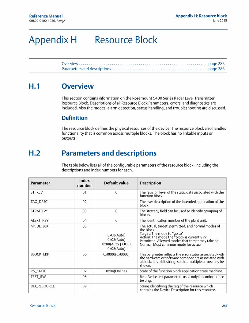
Reference Manual 00809-0100-4026, Rev JA
Appendix H: Resource blockJune 2015
Appendix H Resource Block
Overview . . . . . . . . . . . . . . . . . . . . . . . . . . . . . . . . . . . . . . . . . . . . . . . . . . . . . . . . . . . . . . . . . . . page 283Parameters and descriptions . . . . . . . . . . . . . . . . . . . . . . . . . . . . . . . . . . . . . . . . . . . . . . . . . . page 283
H.1 Overview
This section contains information on the Rosemount 5400 Series Radar Level Transmitter Resource Block. Descriptions of all Resource Block Parameters, errors, and diagnostics are included. Also the modes, alarm detection, status handling, and troubleshooting are discussed.
Definition
The resource block defines the physical resources of the device. The resource block also handles functionality that is common across multiple blocks. The block has no linkable inputs or outputs.
H.2 Parameters and descriptions
The table below lists all of the configurable parameters of the resource block, including the descriptions and index numbers for each.
ParameterIndex
numberDefault value Description
ST_REV 01 0 The revision level of the static data associated with the function block.
TAG_DESC 02 The user description of the intended application of the block.
STRATEGY 03 0 The strategy field can be used to identify grouping of blocks.
ALERT_KEY 04 0 The identification number of the plant unit.
MODE_BLK 05
0x08(Auto)0x08(Auto)
0x88(Auto | OOS)0x08(Auto)
The actual, target, permitted, and normal modes of the block:Target: The mode to “go to”Actual: The mode the “block is currently in”Permitted: Allowed modes that target may take onNormal: Most common mode for actual
BLOCK_ERR 06 0x0000(0x0000) This parameter reflects the error status associated with the hardware or software components associated with a block. It is a bit string, so that multiple errors may be shown.
RS_STATE 07 0x04(Online) State of the function block application state machine.
TEST_RW 08 Read/write test parameter - used only for conformance testing.
DD_RESOURCE 09 String identifying the tag of the resource which contains the Device Description for this resource.
283Resource Block
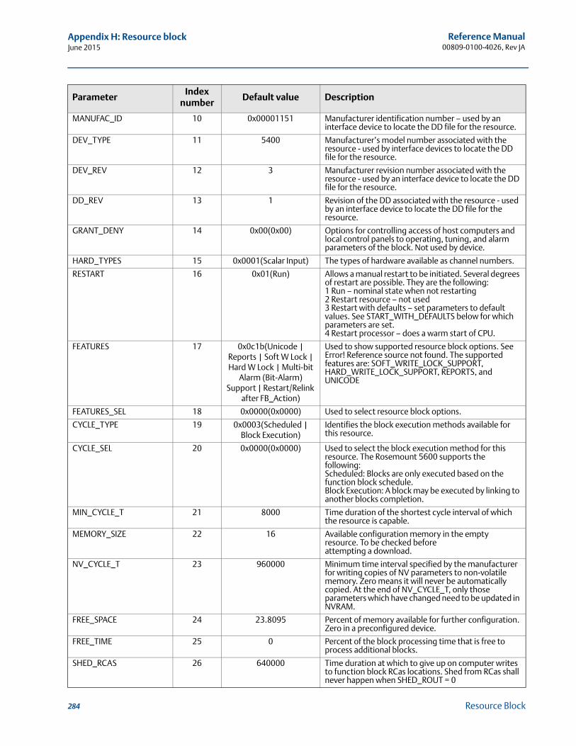
Reference Manual00809-0100-4026, Rev JA
Appendix H: Resource blockJune 2015
MANUFAC_ID 10 0x00001151 Manufacturer identification number – used by an interface device to locate the DD file for the resource.
DEV_TYPE 11 5400 Manufacturer’s model number associated with the resource - used by interface devices to locate the DD file for the resource.
DEV_REV 12 3 Manufacturer revision number associated with the resource - used by an interface device to locate the DD file for the resource.
DD_REV 13 1 Revision of the DD associated with the resource - used by an interface device to locate the DD file for the resource.
GRANT_DENY 14 0x00(0x00) Options for controlling access of host computers and local control panels to operating, tuning, and alarm parameters of the block. Not used by device.
HARD_TYPES 15 0x0001(Scalar Input) The types of hardware available as channel numbers.
RESTART 16 0x01(Run) Allows a manual restart to be initiated. Several degrees of restart are possible. They are the following:1 Run – nominal state when not restarting2 Restart resource – not used 3 Restart with defaults – set parameters to default values. See START_WITH_DEFAULTS below for which parameters are set.4 Restart processor – does a warm start of CPU.
FEATURES 17 0x0c1b(Unicode | Reports | Soft W Lock | Hard W Lock | Multi-bit
Alarm (Bit-Alarm) Support | Restart/Relink
after FB_Action)
Used to show supported resource block options. See Error! Reference source not found. The supported features are: SOFT_WRITE_LOCK_SUPPORT, HARD_WRITE_LOCK_SUPPORT, REPORTS, and UNICODE
FEATURES_SEL 18 0x0000(0x0000) Used to select resource block options.
CYCLE_TYPE 19 0x0003(Scheduled | Block Execution)
Identifies the block execution methods available for this resource.
CYCLE_SEL 20 0x0000(0x0000) Used to select the block execution method for this resource. The Rosemount 5600 supports the following:Scheduled: Blocks are only executed based on the function block schedule.Block Execution: A block may be executed by linking to another blocks completion.
MIN_CYCLE_T 21 8000 Time duration of the shortest cycle interval of which the resource is capable.
MEMORY_SIZE 22 16 Available configuration memory in the empty resource. To be checked before attempting a download.
NV_CYCLE_T 23 960000 Minimum time interval specified by the manufacturer for writing copies of NV parameters to non-volatile memory. Zero means it will never be automatically copied. At the end of NV_CYCLE_T, only those parameters which have changed need to be updated in NVRAM.
FREE_SPACE 24 23.8095 Percent of memory available for further configuration. Zero in a preconfigured device.
FREE_TIME 25 0 Percent of the block processing time that is free to process additional blocks.
SHED_RCAS 26 640000 Time duration at which to give up on computer writes to function block RCas locations. Shed from RCas shall never happen when SHED_ROUT = 0
ParameterIndex
numberDefault value Description
284 Resource Block
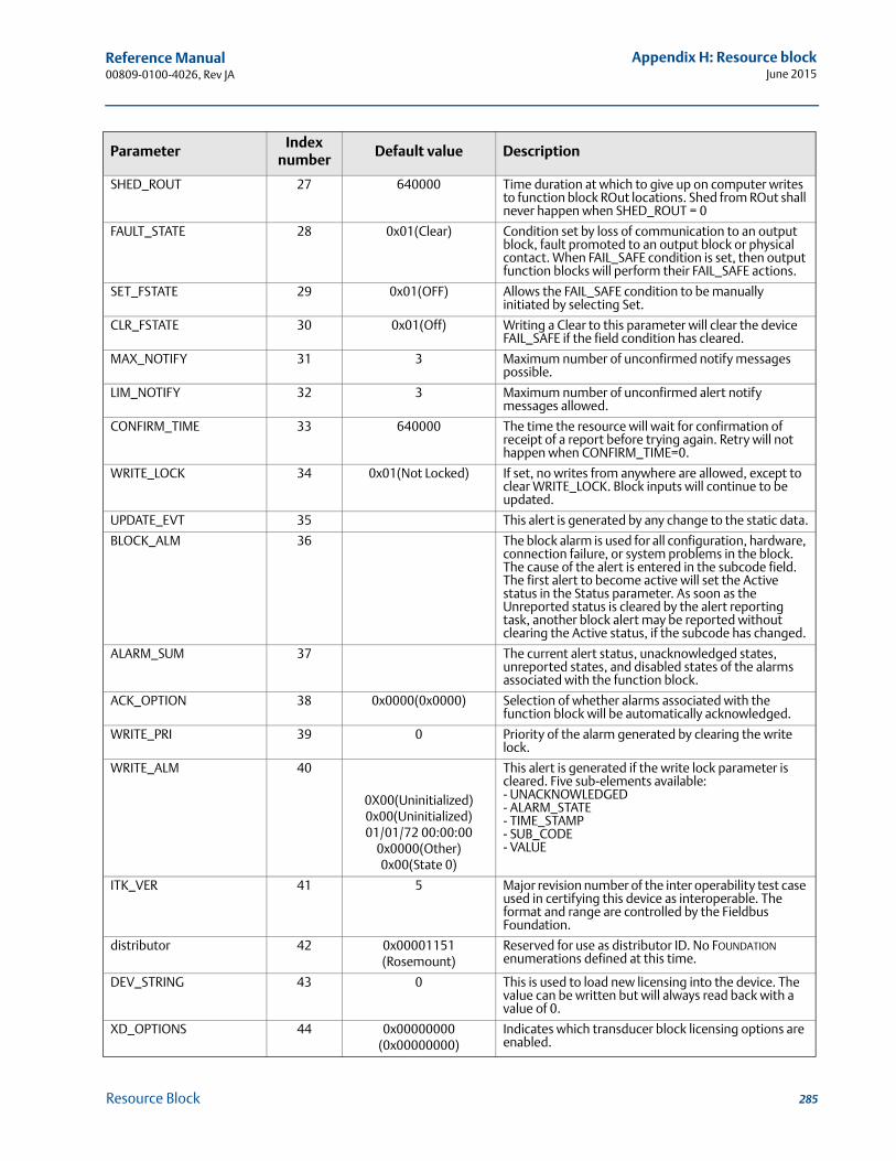
Reference Manual 00809-0100-4026, Rev JA
Appendix H: Resource blockJune 2015
SHED_ROUT 27 640000 Time duration at which to give up on computer writes to function block ROut locations. Shed from ROut shall never happen when SHED_ROUT = 0
FAULT_STATE 28 0x01(Clear) Condition set by loss of communication to an output block, fault promoted to an output block or physical contact. When FAIL_SAFE condition is set, then output function blocks will perform their FAIL_SAFE actions.
SET_FSTATE 29 0x01(OFF) Allows the FAIL_SAFE condition to be manually initiated by selecting Set.
CLR_FSTATE 30 0x01(Off) Writing a Clear to this parameter will clear the device FAIL_SAFE if the field condition has cleared.
MAX_NOTIFY 31 3 Maximum number of unconfirmed notify messages possible.
LIM_NOTIFY 32 3 Maximum number of unconfirmed alert notify messages allowed.
CONFIRM_TIME 33 640000 The time the resource will wait for confirmation of receipt of a report before trying again. Retry will not happen when CONFIRM_TIME=0.
WRITE_LOCK 34 0x01(Not Locked) If set, no writes from anywhere are allowed, except to clear WRITE_LOCK. Block inputs will continue to be updated.
UPDATE_EVT 35 This alert is generated by any change to the static data.
BLOCK_ALM 36 The block alarm is used for all configuration, hardware, connection failure, or system problems in the block. The cause of the alert is entered in the subcode field. The first alert to become active will set the Active status in the Status parameter. As soon as the Unreported status is cleared by the alert reporting task, another block alert may be reported without clearing the Active status, if the subcode has changed.
ALARM_SUM 37 The current alert status, unacknowledged states, unreported states, and disabled states of the alarms associated with the function block.
ACK_OPTION 38 0x0000(0x0000) Selection of whether alarms associated with the function block will be automatically acknowledged.
WRITE_PRI 39 0 Priority of the alarm generated by clearing the write lock.
WRITE_ALM 40
0X00(Uninitialized)0x00(Uninitialized)01/01/72 00:00:00
0x0000(Other)0x00(State 0)
This alert is generated if the write lock parameter is cleared. Five sub-elements available:- UNACKNOWLEDGED- ALARM_STATE- TIME_STAMP- SUB_CODE- VALUE
ITK_VER 41 5 Major revision number of the inter operability test case used in certifying this device as interoperable. The format and range are controlled by the Fieldbus Foundation.
distributor 42 0x00001151(Rosemount)
Reserved for use as distributor ID. No FOUNDATION enumerations defined at this time.
DEV_STRING 43 0 This is used to load new licensing into the device. The value can be written but will always read back with a value of 0.
XD_OPTIONS 44 0x00000000(0x00000000)
Indicates which transducer block licensing options are enabled.
ParameterIndex
numberDefault value Description
285Resource Block
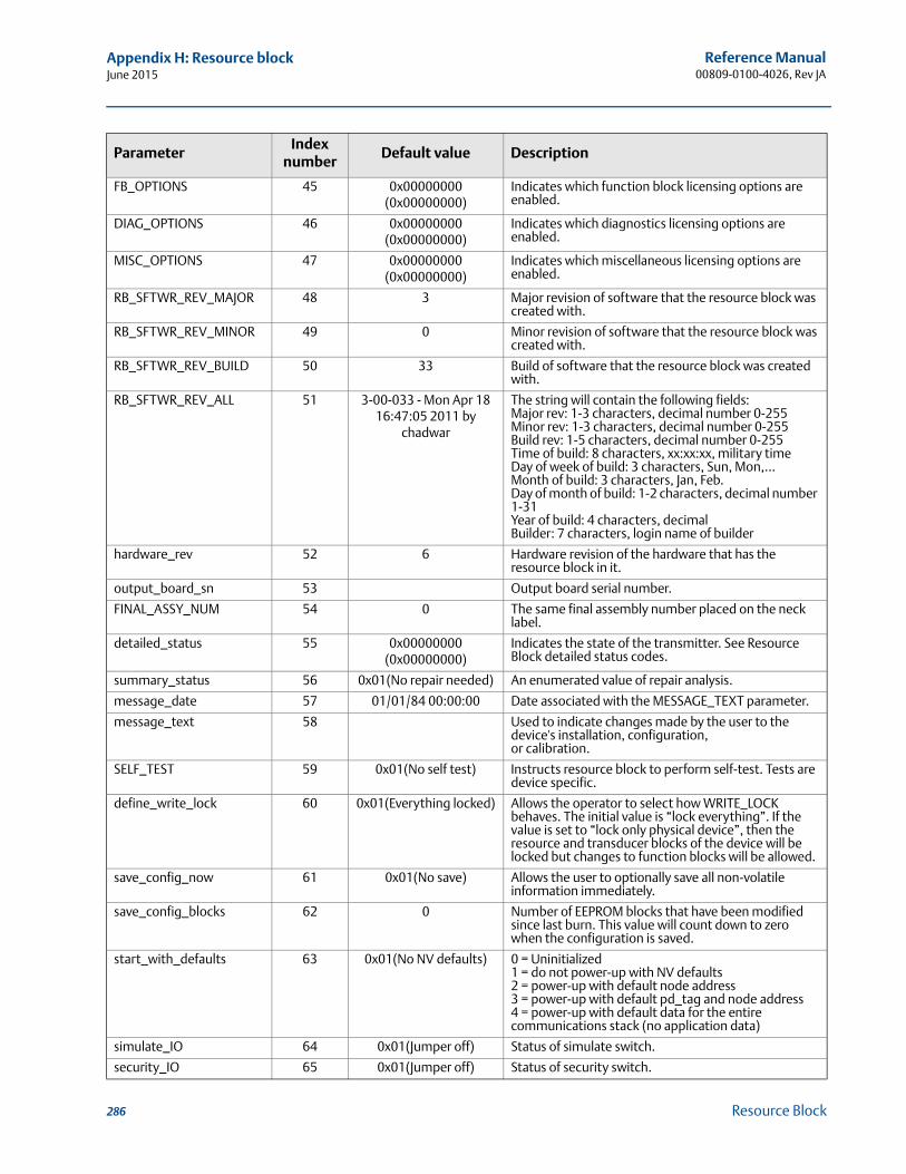
Reference Manual00809-0100-4026, Rev JA
Appendix H: Resource blockJune 2015
FB_OPTIONS 45 0x00000000(0x00000000)
Indicates which function block licensing options are enabled.
DIAG_OPTIONS 46 0x00000000(0x00000000)
Indicates which diagnostics licensing options are enabled.
MISC_OPTIONS 47 0x00000000(0x00000000)
Indicates which miscellaneous licensing options are enabled.
RB_SFTWR_REV_MAJOR 48 3 Major revision of software that the resource block was created with.
RB_SFTWR_REV_MINOR 49 0 Minor revision of software that the resource block was created with.
RB_SFTWR_REV_BUILD 50 33 Build of software that the resource block was created with.
RB_SFTWR_REV_ALL 51 3-00-033 - Mon Apr 18 16:47:05 2011 by
chadwar
The string will contain the following fields:Major rev: 1-3 characters, decimal number 0-255Minor rev: 1-3 characters, decimal number 0-255Build rev: 1-5 characters, decimal number 0-255Time of build: 8 characters, xx:xx:xx, military timeDay of week of build: 3 characters, Sun, Mon,...Month of build: 3 characters, Jan, Feb.Day of month of build: 1-2 characters, decimal number 1-31Year of build: 4 characters, decimalBuilder: 7 characters, login name of builder
hardware_rev 52 6 Hardware revision of the hardware that has the resource block in it.
output_board_sn 53 Output board serial number.
FINAL_ASSY_NUM 54 0 The same final assembly number placed on the neck label.
detailed_status 55 0x00000000(0x00000000)
Indicates the state of the transmitter. See Resource Block detailed status codes.
summary_status 56 0x01(No repair needed) An enumerated value of repair analysis.
message_date 57 01/01/84 00:00:00 Date associated with the MESSAGE_TEXT parameter.
message_text 58 Used to indicate changes made by the user to the device's installation, configuration,or calibration.
SELF_TEST 59 0x01(No self test) Instructs resource block to perform self-test. Tests are device specific.
define_write_lock 60 0x01(Everything locked) Allows the operator to select how WRITE_LOCK behaves. The initial value is “lock everything”. If the value is set to “lock only physical device”, then the resource and transducer blocks of the device will be locked but changes to function blocks will be allowed.
save_config_now 61 0x01(No save) Allows the user to optionally save all non-volatile information immediately.
save_config_blocks 62 0 Number of EEPROM blocks that have been modified since last burn. This value will count down to zero when the configuration is saved.
start_with_defaults 63 0x01(No NV defaults) 0 = Uninitialized1 = do not power-up with NV defaults2 = power-up with default node address3 = power-up with default pd_tag and node address4 = power-up with default data for the entire communications stack (no application data)
simulate_IO 64 0x01(Jumper off) Status of simulate switch.
security_IO 65 0x01(Jumper off) Status of security switch.
ParameterIndex
numberDefault value Description
286 Resource Block
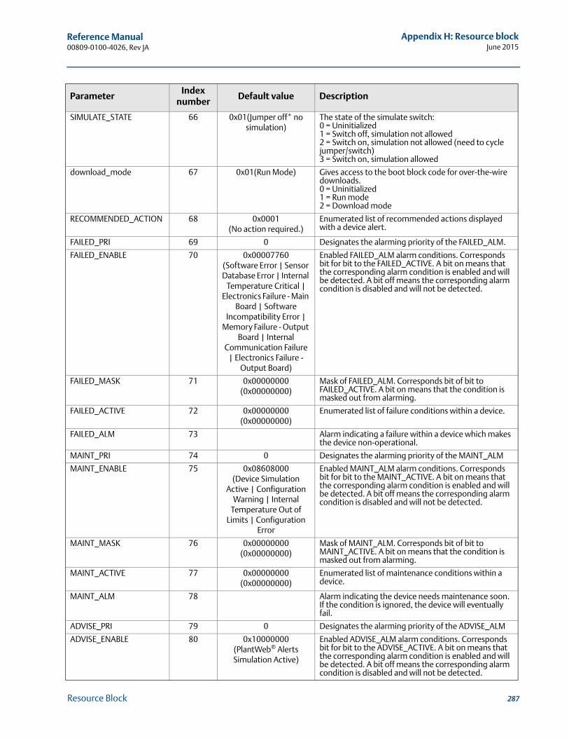
Reference Manual 00809-0100-4026, Rev JA
Appendix H: Resource blockJune 2015
SIMULATE_STATE 66 0x01(Jumper off* no simulation)
The state of the simulate switch:0 = Uninitialized1 = Switch off, simulation not allowed2 = Switch on, simulation not allowed (need to cycle jumper/switch)3 = Switch on, simulation allowed
download_mode 67 0x01(Run Mode) Gives access to the boot block code for over-the-wire downloads.0 = Uninitialized 1 = Run mode2 = Download mode
RECOMMENDED_ACTION 68 0x0001(No action required.)
Enumerated list of recommended actions displayed with a device alert.
FAILED_PRI 69 0 Designates the alarming priority of the FAILED_ALM.
FAILED_ENABLE 70 0x00007760(Software Error | Sensor Database Error | Internal
Temperature Critical | Electronics Failure - Main
Board | Software Incompatibility Error |
Memory Failure - Output Board | Internal
Communication Failure | Electronics Failure -
Output Board)
Enabled FAILED_ALM alarm conditions. Corresponds bit for bit to the FAILED_ACTIVE. A bit on means that the corresponding alarm condition is enabled and will be detected. A bit off means the corresponding alarm condition is disabled and will not be detected.
FAILED_MASK 71 0x00000000(0x00000000)
Mask of FAILED_ALM. Corresponds bit of bit to FAILED_ACTIVE. A bit on means that the condition is masked out from alarming.
FAILED_ACTIVE 72 0x00000000(0x00000000)
Enumerated list of failure conditions within a device.
FAILED_ALM 73 Alarm indicating a failure within a device which makes the device non-operational.
MAINT_PRI 74 0 Designates the alarming priority of the MAINT_ALM
MAINT_ENABLE 75 0x08608000(Device Simulation
Active | Configuration Warning | Internal
Temperature Out of Limits | Configuration
Error
Enabled MAINT_ALM alarm conditions. Corresponds bit for bit to the MAINT_ACTIVE. A bit on means that the corresponding alarm condition is enabled and will be detected. A bit off means the corresponding alarm condition is disabled and will not be detected.
MAINT_MASK 76 0x00000000(0x00000000)
Mask of MAINT_ALM. Corresponds bit of bit to MAINT_ACTIVE. A bit on means that the condition is masked out from alarming.
MAINT_ACTIVE 77 0x00000000(0x00000000)
Enumerated list of maintenance conditions within a device.
MAINT_ALM 78 Alarm indicating the device needs maintenance soon. If the condition is ignored, the device will eventually fail.
ADVISE_PRI 79 0 Designates the alarming priority of the ADVISE_ALM
ADVISE_ENABLE 80 0x10000000(PlantWeb® Alerts Simulation Active)
Enabled ADVISE_ALM alarm conditions. Corresponds bit for bit to the ADVISE_ACTIVE. A bit on means that the corresponding alarm condition is enabled and will be detected. A bit off means the corresponding alarm condition is disabled and will not be detected.
ParameterIndex
numberDefault value Description
287Resource Block
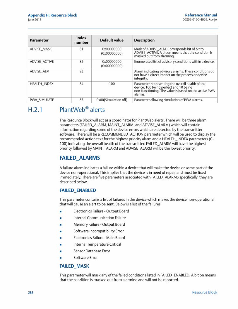
Reference Manual00809-0100-4026, Rev JA
Appendix H: Resource blockJune 2015
H.2.1 PlantWeb® alerts
The Resource Block will act as a coordinator for PlantWeb alerts. There will be three alarm parameters (FAILED_ALARM, MAINT_ALARM, and ADVISE_ALARM) which will contain information regarding some of the device errors which are detected by the transmitter software. There will be a RECOMMENDED_ACTION parameter which will be used to display the recommended action text for the highest priority alarm and a HEALTH_INDEX parameters (0 - 100) indicating the overall health of the transmitter. FAILED_ALARM will have the highest priority followed by MAINT_ALARM and ADVISE_ALARM will be the lowest priority.
FAILED_ALARMS
A failure alarm indicates a failure within a device that will make the device or some part of the device non-operational. This implies that the device is in need of repair and must be fixed immediately. There are five parameters associated with FAILED_ALARMS specifically, they are described below.
FAILED_ENABLED
This parameter contains a list of failures in the device which makes the device non-operational that will cause an alert to be sent. Below is a list of the failures:
Electronics Failure - Output Board
Internal Communication Failure
Memory Failure - Output Board
Software Incompatibility Error
Electronics Failure - Main Board
Internal Temperature Critical
Sensor Database Error
Software Error
FAILED_MASK
This parameter will mask any of the failed conditions listed in FAILED_ENABLED. A bit on means that the condition is masked out from alarming and will not be reported.
ADVISE_MASK 81 0x00000000(0x00000000)
Mask of ADVISE_ALM. Corresponds bit of bit to ADVISE_ACTIVE. A bit on means that the condition is masked out from alarming.
ADVISE_ACTIVE 82 0x00000000(0x00000000)
Enumerated list of advisory conditions within a device.
ADVISE_ALM 83 Alarm indicating advisory alarms. These conditions do not have a direct impact on the process or device integrity.
HEALTH_INDEX 84 100 Parameter representing the overall health of the device, 100 being perfect and 10 being non-functioning. The value is based on the active PWA alarms.
PWA_SIMULATE 85 0x00(Simulation off) Parameter allowing simulation of PWA alarms.
ParameterIndex
numberDefault value Description
288 Resource Block
Reference Manual 00809-0100-4026, Rev JA
Appendix H: Resource blockJune 2015
FAILED_PRI
Designates the alerting priority of the FAILED_ALM, see “Alarm priority” on page 291. The default is 0 and the recommended values are between 8 and 15.
FAILED_ACTIVE
This parameter displays which of the alarms is active. Only the alarm with the highest priority will be displayed. This priority is not the same as the FAILED_PRI parameter described above. This priority is hard coded within the device and is not user configurable.
FAILED_ALM
Alarm indicating a failure within a device which makes the device non-operational.
MAINT_ALARMS
A maintenance alarm indicates the device or some part of the device needs maintenance soon. If the condition is ignored, the device will eventually fail. There are five parameters associated with MAINT_ALARMS, they are described below.
MAINT_ENABLED
The MAINT_ENABLED parameter contains a list of conditions indicating the device or some part of the device needs maintenance soon.
Below is a list of the conditions:
Configuration Error
Level Measurement Failure
Volume Measurement Failure
Internal Temperature Out of Limits
Configuration Warning
Volume Measurement Warning
Device Simulation Active
MAINT_MASK
The MAINT_MASK parameter will mask any of the failed conditions listed in MAINT_ENABLED. A bit on means that the condition is masked out from alarming and will not be reported.
MAINT_PRI
MAINT_PRI designates the alarming priority of the MAINT_ALM, see “Recommended actions for PlantWeb alerts” on page 292. The default is 0 and the recommended values is 3 to 7.
MAINT_ACTIVE
The MAINT_ACTIVE parameter displays which of the alarms is active. Only the condition with the highest priority will be displayed. This priority is not the same as the MAINT_PRI parameter described above. This priority is hard coded within the device and is not user configurable.
289Resource Block
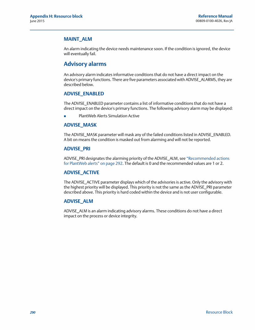
Reference Manual00809-0100-4026, Rev JA
Appendix H: Resource blockJune 2015
MAINT_ALM
An alarm indicating the device needs maintenance soon. If the condition is ignored, the device will eventually fail.
Advisory alarms
An advisory alarm indicates informative conditions that do not have a direct impact on the device's primary functions. There are five parameters associated with ADVISE_ALARMS, they are described below.
ADVISE_ENABLED
The ADVISE_ENABLED parameter contains a list of informative conditions that do not have a direct impact on the device's primary functions. The following advisory alarm may be displayed:
PlantWeb Alerts Simulation Active
ADVISE_MASK
The ADVISE_MASK parameter will mask any of the failed conditions listed in ADVISE_ENABLED. A bit on means the condition is masked out from alarming and will not be reported.
ADVISE_PRI
ADVISE_PRI designates the alarming priority of the ADVISE_ALM, see “Recommended actions for PlantWeb alerts” on page 292. The default is 0 and the recommended values are 1 or 2.
ADVISE_ACTIVE
The ADVISE_ACTIVE parameter displays which of the advisories is active. Only the advisory with the highest priority will be displayed. This priority is not the same as the ADVISE_PRI parameter described above. This priority is hard coded within the device and is not user configurable.
ADVISE_ALM
ADVISE_ALM is an alarm indicating advisory alarms. These conditions do not have a direct impact on the process or device integrity.
290 Resource Block
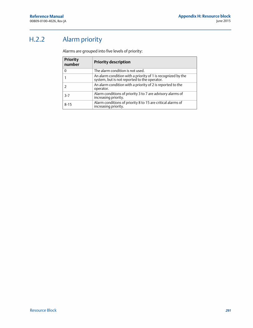
Reference Manual 00809-0100-4026, Rev JA
Appendix H: Resource blockJune 2015
H.2.2 Alarm priority
Alarms are grouped into five levels of priority:
Priority number
Priority description
0 The alarm condition is not used.
1 An alarm condition with a priority of 1 is recognized by the system, but is not reported to the operator.
2 An alarm condition with a priority of 2 is reported to the operator.
3-7 Alarm conditions of priority 3 to 7 are advisory alarms of increasing priority.
8-15 Alarm conditions of priority 8 to 15 are critical alarms of increasing priority.
291Resource Block
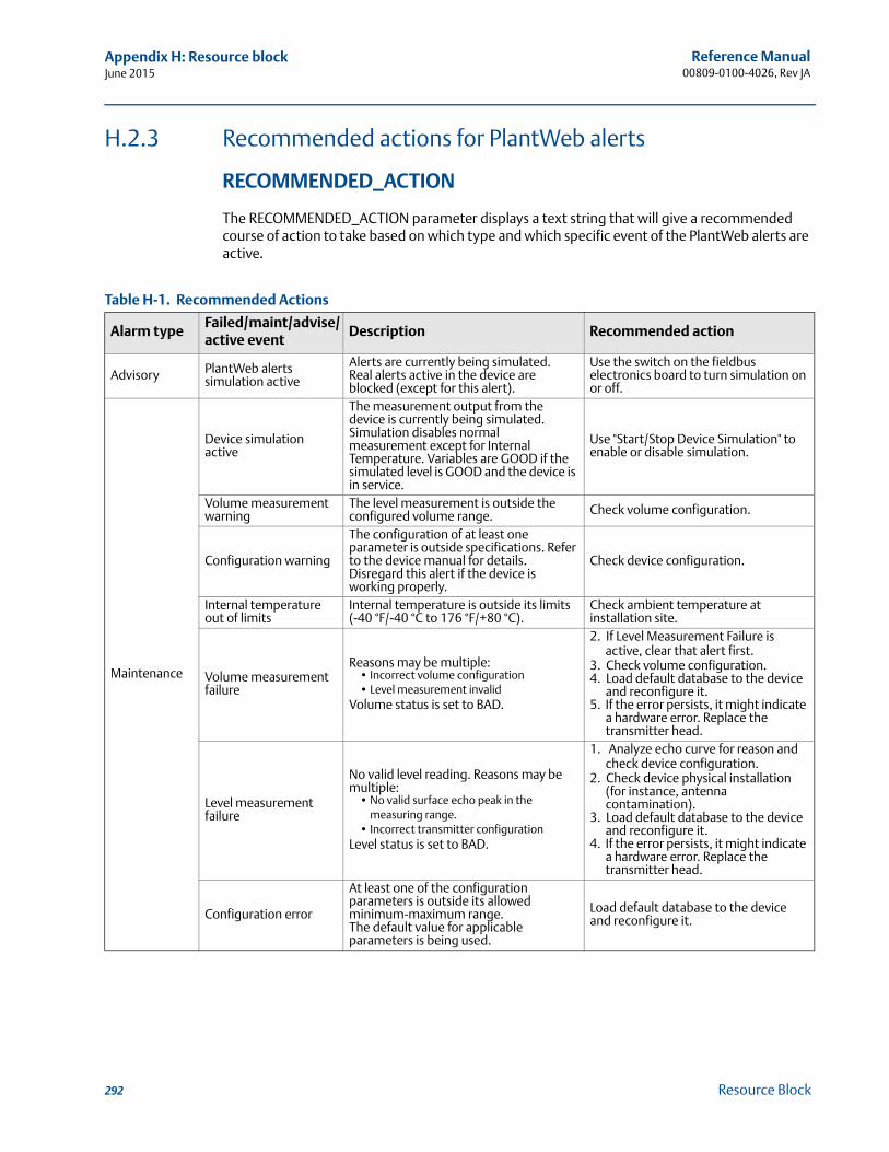
Reference Manual00809-0100-4026, Rev JA
Appendix H: Resource blockJune 2015
H.2.3 Recommended actions for PlantWeb alerts
RECOMMENDED_ACTION
The RECOMMENDED_ACTION parameter displays a text string that will give a recommended course of action to take based on which type and which specific event of the PlantWeb alerts are active.
Table H-1. Recommended Actions
Alarm typeFailed/maint/advise/ active event
Description Recommended action
Advisory PlantWeb alerts simulation active
Alerts are currently being simulated.Real alerts active in the device are blocked (except for this alert).
Use the switch on the fieldbus electronics board to turn simulation on or off.
Maintenance
Device simulation active
The measurement output from the device is currently being simulated.Simulation disables normal measurement except for Internal Temperature. Variables are GOOD if the simulated level is GOOD and the device is in service.
Use "Start/Stop Device Simulation" to enable or disable simulation.
Volume measurement warning
The level measurement is outside the configured volume range. Check volume configuration.
Configuration warning
The configuration of at least one parameter is outside specifications. Refer to the device manual for details. Disregard this alert if the device is working properly.
Check device configuration.
Internal temperature out of limits
Internal temperature is outside its limits (-40 °F/-40 °C to 176 °F/+80 °C).
Check ambient temperature at installation site.
Volume measurement failure
Reasons may be multiple:• Incorrect volume configuration• Level measurement invalid
Volume status is set to BAD.
2. If Level Measurement Failure is active, clear that alert first.
3. Check volume configuration.4. Load default database to the device
and reconfigure it.5. If the error persists, it might indicate
a hardware error. Replace the transmitter head.
Level measurement failure
No valid level reading. Reasons may be multiple:
• No valid surface echo peak in the measuring range.
• Incorrect transmitter configurationLevel status is set to BAD.
1. Analyze echo curve for reason and check device configuration.
2. Check device physical installation (for instance, antenna contamination).
3. Load default database to the device and reconfigure it.
4. If the error persists, it might indicate a hardware error. Replace the transmitter head.
Configuration error
At least one of the configuration parameters is outside its allowed minimum-maximum range.The default value for applicable parameters is being used.
Load default database to the device and reconfigure it.
292 Resource Block
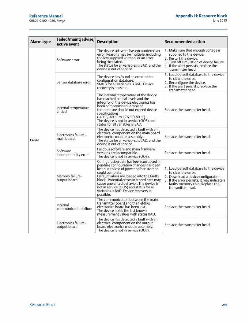
Reference Manual 00809-0100-4026, Rev JA
Appendix H: Resource blockJune 2015
Failed
Software error
The device software has encountered an error. Reasons may be multiple, including too low supplied voltage, or an error being simulated.The status for all variables is BAD, and the device is out of service.
1. Make sure that enough voltage is supplied to the device.
2. Restart the device.3. Turn off simulation of device failure.4. If the alert persists, replace the
transmitter head.
Sensor database error
The device has found an error in the configuration database.Status for all variables is BAD. Device recovery is possible.
1. Load default database to the device to clear the error.
2. Reconfigure the device.3. If the alert persists, replace the
transmitter head.
Internal temperature critical
The internal temperature of the device has reached critical levels and the integrity of the device electronics has been compromised. Ambient temperature should not exceed device specifications (-40 °F/-40 °C to 176 °F/+80 °C).The device is not in service (OOS) and status for all variables is BAD.
Replace the transmitter head.
Electronics failure – main board
The device has detected a fault with an electrical component on the main board electronics module assembly.The status for all variables is BAD, and the device is out of service.
Replace the transmitter head.
Software incompatibility error
Fieldbus software and main firmware versions are incompatible.The device is not in service (OOS).
Replace the transmitter head.
Memory failure - output board
Configuration data has been corrupted or pending configuration changes has been lost due to loss of power before storage could complete.Default values are loaded into the faulty block. Potential errors in stored data may cause unwanted behavior. The device is not in service (OOS) and status for all variables is BAD. Device recovery is possible.
1. Load default database to the device to clear the error.
2. Download a device configuration.3. If the error persists, it may indicate a
faulty memory chip. Replace the transmitter head.
Internal communication failure
The communication between the main transmitter board and the fieldbus electronics board has been lost.The device holds the last known measurement values with status BAD.
Replace the transmitter head.
Electronics failure - output board
The device has detected a fault with an electrical component on the output board electronics module assembly.The device is not in service (OOS).
Replace the transmitter head.
Alarm typeFailed/maint/advise/ active event
Description Recommended action
293Resource Block

Reference Manual00809-0100-4026, Rev JA
Appendix H: Resource blockJune 2015
294 Resource Block
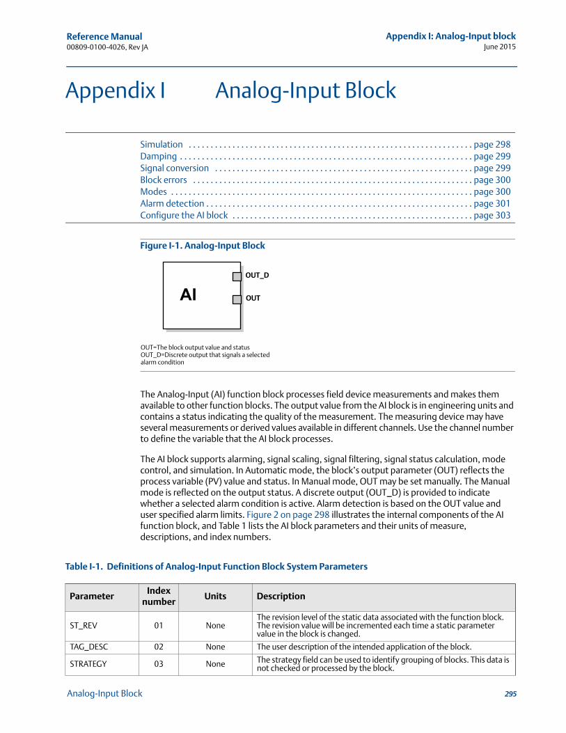
Reference Manual 00809-0100-4026, Rev JA
Appendix I: Analog-Input blockJune 2015
Appendix I Analog-Input Block
Simulation . . . . . . . . . . . . . . . . . . . . . . . . . . . . . . . . . . . . . . . . . . . . . . . . . . . . . . . . . . . . . . . . . page 298Damping . . . . . . . . . . . . . . . . . . . . . . . . . . . . . . . . . . . . . . . . . . . . . . . . . . . . . . . . . . . . . . . . . . . page 299Signal conversion . . . . . . . . . . . . . . . . . . . . . . . . . . . . . . . . . . . . . . . . . . . . . . . . . . . . . . . . . . . page 299Block errors . . . . . . . . . . . . . . . . . . . . . . . . . . . . . . . . . . . . . . . . . . . . . . . . . . . . . . . . . . . . . . . . page 300Modes . . . . . . . . . . . . . . . . . . . . . . . . . . . . . . . . . . . . . . . . . . . . . . . . . . . . . . . . . . . . . . . . . . . . . page 300Alarm detection . . . . . . . . . . . . . . . . . . . . . . . . . . . . . . . . . . . . . . . . . . . . . . . . . . . . . . . . . . . . . page 301Configure the AI block . . . . . . . . . . . . . . . . . . . . . . . . . . . . . . . . . . . . . . . . . . . . . . . . . . . . . . . page 303
Figure I-1. Analog-Input Block
The Analog-Input (AI) function block processes field device measurements and makes them available to other function blocks. The output value from the AI block is in engineering units and contains a status indicating the quality of the measurement. The measuring device may have several measurements or derived values available in different channels. Use the channel number to define the variable that the AI block processes.
The AI block supports alarming, signal scaling, signal filtering, signal status calculation, mode control, and simulation. In Automatic mode, the block’s output parameter (OUT) reflects the process variable (PV) value and status. In Manual mode, OUT may be set manually. The Manual mode is reflected on the output status. A discrete output (OUT_D) is provided to indicate whether a selected alarm condition is active. Alarm detection is based on the OUT value and user specified alarm limits. Figure 2 on page 298 illustrates the internal components of the AI function block, and Table 1 lists the AI block parameters and their units of measure, descriptions, and index numbers.
Table I-1. Definitions of Analog-Input Function Block System Parameters
ParameterIndex
numberUnits Description
ST_REV 01 NoneThe revision level of the static data associated with the function block. The revision value will be incremented each time a static parameter value in the block is changed.
TAG_DESC 02 None The user description of the intended application of the block.
STRATEGY 03 None The strategy field can be used to identify grouping of blocks. This data is not checked or processed by the block.
OUT=The block output value and statusOUT_D=Discrete output that signals a selected alarm condition
OUT_D
AI OUT
295Analog-Input Block
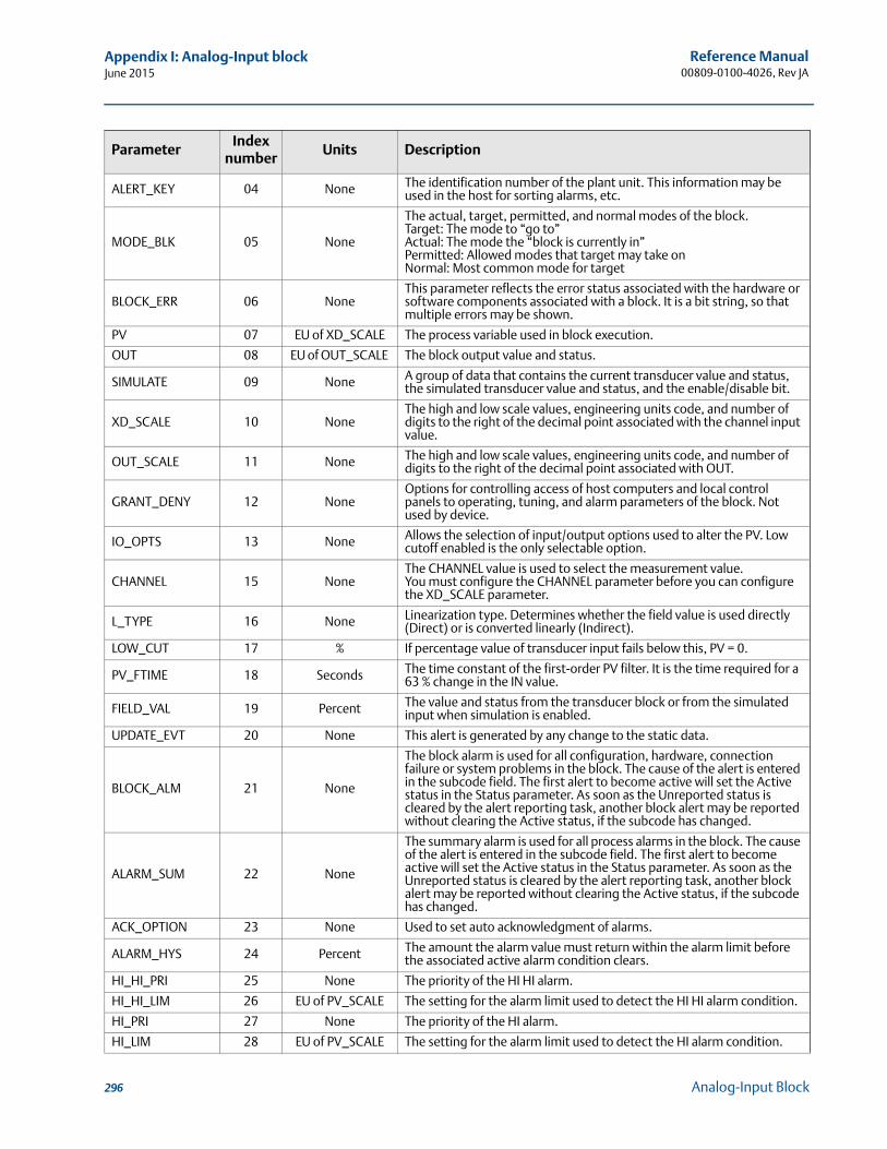
Reference Manual00809-0100-4026, Rev JA
Appendix I: Analog-Input blockJune 2015
ALERT_KEY 04 None The identification number of the plant unit. This information may be used in the host for sorting alarms, etc.
MODE_BLK 05 None
The actual, target, permitted, and normal modes of the block. Target: The mode to “go to”Actual: The mode the “block is currently in”Permitted: Allowed modes that target may take onNormal: Most common mode for target
BLOCK_ERR 06 NoneThis parameter reflects the error status associated with the hardware or software components associated with a block. It is a bit string, so that multiple errors may be shown.
PV 07 EU of XD_SCALE The process variable used in block execution.
OUT 08 EU of OUT_SCALE The block output value and status.
SIMULATE 09 None A group of data that contains the current transducer value and status, the simulated transducer value and status, and the enable/disable bit.
XD_SCALE 10 NoneThe high and low scale values, engineering units code, and number of digits to the right of the decimal point associated with the channel input value.
OUT_SCALE 11 None The high and low scale values, engineering units code, and number of digits to the right of the decimal point associated with OUT.
GRANT_DENY 12 NoneOptions for controlling access of host computers and local control panels to operating, tuning, and alarm parameters of the block. Not used by device.
IO_OPTS 13 None Allows the selection of input/output options used to alter the PV. Low cutoff enabled is the only selectable option.
CHANNEL 15 NoneThe CHANNEL value is used to select the measurement value.You must configure the CHANNEL parameter before you can configure the XD_SCALE parameter.
L_TYPE 16 None Linearization type. Determines whether the field value is used directly (Direct) or is converted linearly (Indirect).
LOW_CUT 17 % If percentage value of transducer input fails below this, PV = 0.
PV_FTIME 18 Seconds The time constant of the first-order PV filter. It is the time required for a 63 % change in the IN value.
FIELD_VAL 19 Percent The value and status from the transducer block or from the simulated input when simulation is enabled.
UPDATE_EVT 20 None This alert is generated by any change to the static data.
BLOCK_ALM 21 None
The block alarm is used for all configuration, hardware, connection failure or system problems in the block. The cause of the alert is entered in the subcode field. The first alert to become active will set the Active status in the Status parameter. As soon as the Unreported status is cleared by the alert reporting task, another block alert may be reported without clearing the Active status, if the subcode has changed.
ALARM_SUM 22 None
The summary alarm is used for all process alarms in the block. The cause of the alert is entered in the subcode field. The first alert to become active will set the Active status in the Status parameter. As soon as the Unreported status is cleared by the alert reporting task, another block alert may be reported without clearing the Active status, if the subcode has changed.
ACK_OPTION 23 None Used to set auto acknowledgment of alarms.
ALARM_HYS 24 Percent The amount the alarm value must return within the alarm limit before the associated active alarm condition clears.
HI_HI_PRI 25 None The priority of the HI HI alarm.
HI_HI_LIM 26 EU of PV_SCALE The setting for the alarm limit used to detect the HI HI alarm condition.
HI_PRI 27 None The priority of the HI alarm.
HI_LIM 28 EU of PV_SCALE The setting for the alarm limit used to detect the HI alarm condition.
ParameterIndex
numberUnits Description
296 Analog-Input Block
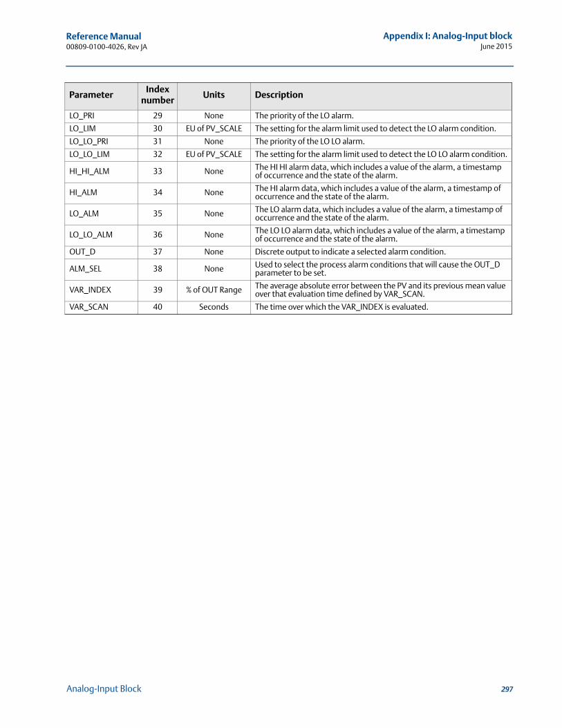
Reference Manual 00809-0100-4026, Rev JA
Appendix I: Analog-Input blockJune 2015
LO_PRI 29 None The priority of the LO alarm.
LO_LIM 30 EU of PV_SCALE The setting for the alarm limit used to detect the LO alarm condition.
LO_LO_PRI 31 None The priority of the LO LO alarm.
LO_LO_LIM 32 EU of PV_SCALE The setting for the alarm limit used to detect the LO LO alarm condition.
HI_HI_ALM 33 None The HI HI alarm data, which includes a value of the alarm, a timestamp of occurrence and the state of the alarm.
HI_ALM 34 None The HI alarm data, which includes a value of the alarm, a timestamp of occurrence and the state of the alarm.
LO_ALM 35 None The LO alarm data, which includes a value of the alarm, a timestamp of occurrence and the state of the alarm.
LO_LO_ALM 36 None The LO LO alarm data, which includes a value of the alarm, a timestamp of occurrence and the state of the alarm.
OUT_D 37 None Discrete output to indicate a selected alarm condition.
ALM_SEL 38 None Used to select the process alarm conditions that will cause the OUT_D parameter to be set.
VAR_INDEX 39 % of OUT Range The average absolute error between the PV and its previous mean value over that evaluation time defined by VAR_SCAN.
VAR_SCAN 40 Seconds The time over which the VAR_INDEX is evaluated.
ParameterIndex
numberUnits Description
297Analog-Input Block
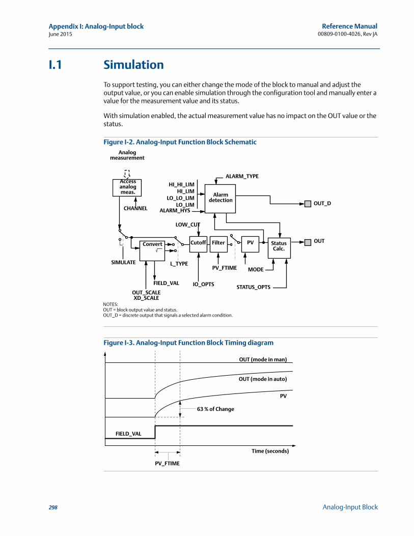
Reference Manual00809-0100-4026, Rev JA
Appendix I: Analog-Input blockJune 2015
I.1 Simulation
To support testing, you can either change the mode of the block to manual and adjust the output value, or you can enable simulation through the configuration tool and manually enter a value for the measurement value and its status.
With simulation enabled, the actual measurement value has no impact on the OUT value or the status.
Figure I-2. Analog-Input Function Block Schematic
Figure I-3. Analog-Input Function Block Timing diagram
Analog measurement
Accessanalogmeas.
CHANNEL
SIMULATE
OUT_SCALEXD_SCALE
FIELD_VAL
L_TYPE
IO_OPTS
PV_FTIME MODE
STATUS_OPTS
HI_HI_LIMHI_LIM
LO_LO_LIMLO_LIM
ALARM_HYS
ALARM_TYPE
OUT_D
OUTPVConvert Cutoff Filter StatusCalc.
Alarm detection
NOTES:OUT = block output value and status.OUT_D = discrete output that signals a selected alarm condition.
LOW_CUT
PV_FTIME
63 % of Change
OUT (mode in man)
OUT (mode in auto)
PV
Time (seconds)
FIELD_VAL
298 Analog-Input Block
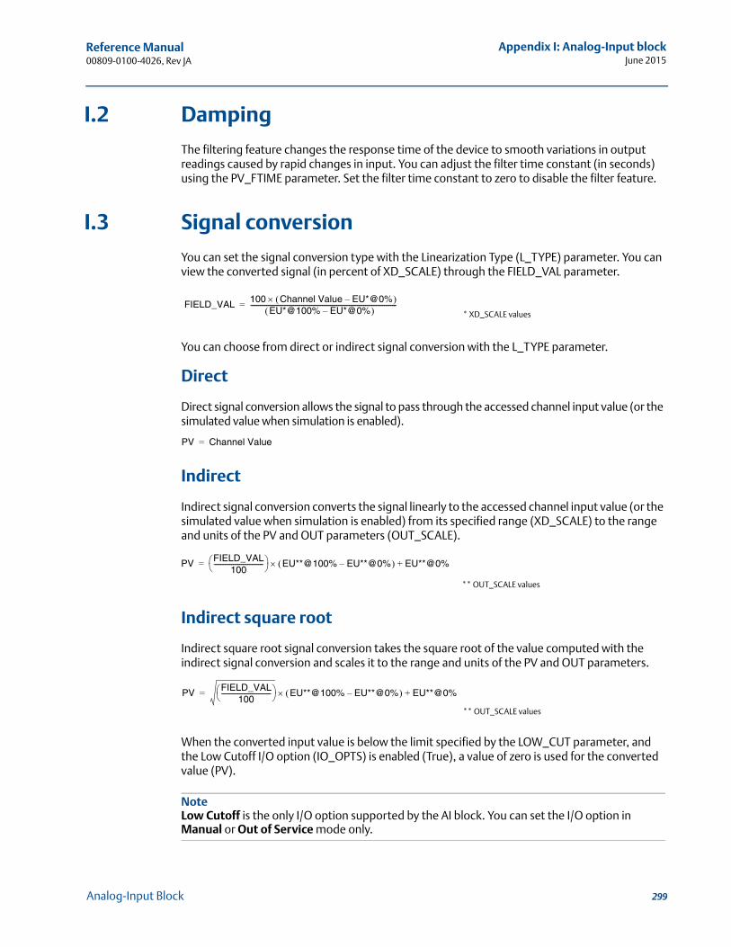
Reference Manual 00809-0100-4026, Rev JA
Appendix I: Analog-Input blockJune 2015
I.2 Damping
The filtering feature changes the response time of the device to smooth variations in output readings caused by rapid changes in input. You can adjust the filter time constant (in seconds) using the PV_FTIME parameter. Set the filter time constant to zero to disable the filter feature.
I.3 Signal conversion
You can set the signal conversion type with the Linearization Type (L_TYPE) parameter. You can view the converted signal (in percent of XD_SCALE) through the FIELD_VAL parameter.
You can choose from direct or indirect signal conversion with the L_TYPE parameter.
Direct
Direct signal conversion allows the signal to pass through the accessed channel input value (or the simulated value when simulation is enabled).
Indirect
Indirect signal conversion converts the signal linearly to the accessed channel input value (or the simulated value when simulation is enabled) from its specified range (XD_SCALE) to the range and units of the PV and OUT parameters (OUT_SCALE).
Indirect square root
Indirect square root signal conversion takes the square root of the value computed with the indirect signal conversion and scales it to the range and units of the PV and OUT parameters.
When the converted input value is below the limit specified by the LOW_CUT parameter, and the Low Cutoff I/O option (IO_OPTS) is enabled (True), a value of zero is used for the converted value (PV).
NoteLow Cutoff is the only I/O option supported by the AI block. You can set the I/O option in Manual or Out of Service mode only.
FIELD_VAL 100 Channel Value EU*@0%– EU*@100% EU*@0%–
--------------------------------------------------------------------------------------------=* XD_SCALE values
PV Channel Value=
PV FIELD_VAL100
------------------------------- EU**@100% EU**@0%– EU**@0%+=
** OUT_SCALE values
PV FIELD_VAL100
------------------------------- EU**@100% EU**@0%– EU**@0%+=
** OUT_SCALE values
299Analog-Input Block
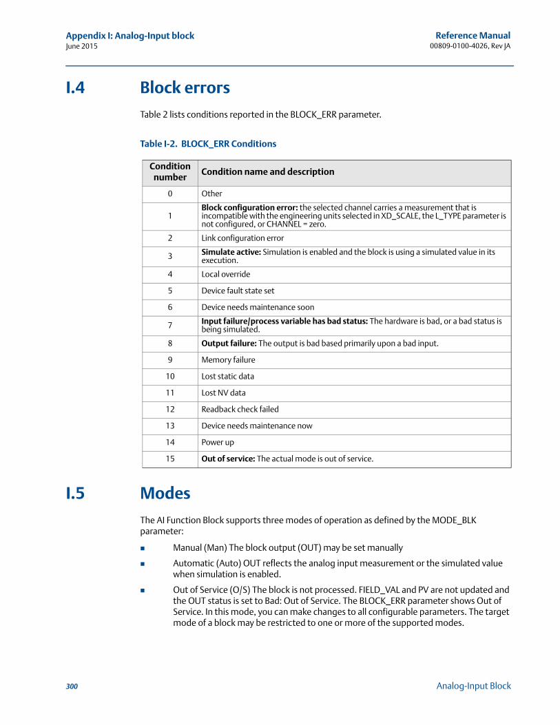
Reference Manual00809-0100-4026, Rev JA
Appendix I: Analog-Input blockJune 2015
I.4 Block errors
Table 2 lists conditions reported in the BLOCK_ERR parameter.
Table I-2. BLOCK_ERR Conditions
I.5 Modes
The AI Function Block supports three modes of operation as defined by the MODE_BLK parameter:
Manual (Man) The block output (OUT) may be set manually
Automatic (Auto) OUT reflects the analog input measurement or the simulated value when simulation is enabled.
Out of Service (O/S) The block is not processed. FIELD_VAL and PV are not updated and the OUT status is set to Bad: Out of Service. The BLOCK_ERR parameter shows Out of Service. In this mode, you can make changes to all configurable parameters. The target mode of a block may be restricted to one or more of the supported modes.
Condition number
Condition name and description
0 Other
1Block configuration error: the selected channel carries a measurement that is incompatible with the engineering units selected in XD_SCALE, the L_TYPE parameter is not configured, or CHANNEL = zero.
2 Link configuration error
3 Simulate active: Simulation is enabled and the block is using a simulated value in its execution.
4 Local override
5 Device fault state set
6 Device needs maintenance soon
7 Input failure/process variable has bad status: The hardware is bad, or a bad status is being simulated.
8 Output failure: The output is bad based primarily upon a bad input.
9 Memory failure
10 Lost static data
11 Lost NV data
12 Readback check failed
13 Device needs maintenance now
14 Power up
15 Out of service: The actual mode is out of service.
300 Analog-Input Block
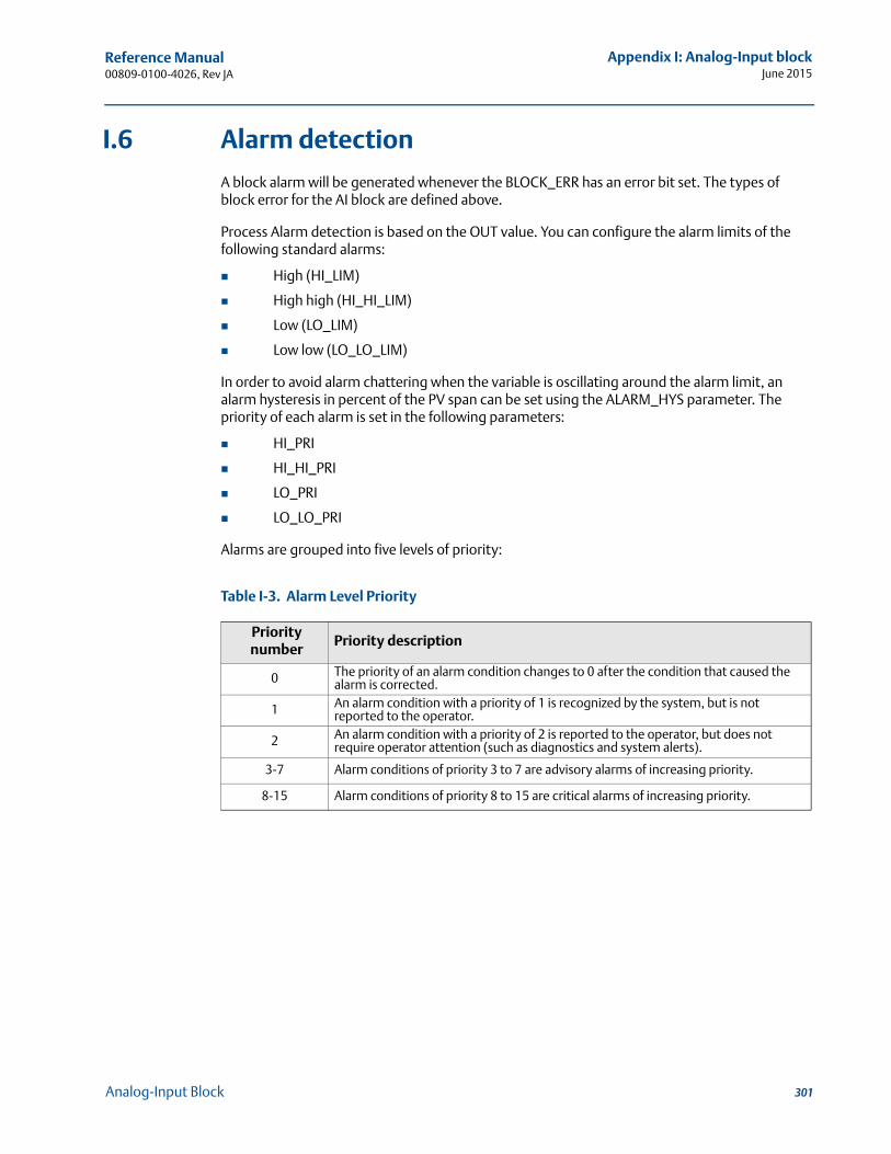
Reference Manual 00809-0100-4026, Rev JA
Appendix I: Analog-Input blockJune 2015
I.6 Alarm detection
A block alarm will be generated whenever the BLOCK_ERR has an error bit set. The types of block error for the AI block are defined above.
Process Alarm detection is based on the OUT value. You can configure the alarm limits of the following standard alarms:
High (HI_LIM)
High high (HI_HI_LIM)
Low (LO_LIM)
Low low (LO_LO_LIM)
In order to avoid alarm chattering when the variable is oscillating around the alarm limit, an alarm hysteresis in percent of the PV span can be set using the ALARM_HYS parameter. The priority of each alarm is set in the following parameters:
HI_PRI
HI_HI_PRI
LO_PRI
LO_LO_PRI
Alarms are grouped into five levels of priority:
Table I-3. Alarm Level Priority
Priority number
Priority description
0 The priority of an alarm condition changes to 0 after the condition that caused the alarm is corrected.
1 An alarm condition with a priority of 1 is recognized by the system, but is not reported to the operator.
2 An alarm condition with a priority of 2 is reported to the operator, but does not require operator attention (such as diagnostics and system alerts).
3-7 Alarm conditions of priority 3 to 7 are advisory alarms of increasing priority.
8-15 Alarm conditions of priority 8 to 15 are critical alarms of increasing priority.
301Analog-Input Block
Reference Manual00809-0100-4026, Rev JA
Appendix I: Analog-Input blockJune 2015
I.6.1 Status handling
Normally, the status of the PV reflects the status of the measurement value, the operating condition of the I/O card, and any active alarm condition. In Auto mode, OUT reflects the value and status quality of the PV. In Man mode, the OUT status constant limit is set to indicate that the value is a constant and the OUT status is Good.
The Uncertain - EU range violation status is always set, and the PV status is set high- or low-limited if the sensor limits for conversion are exceeded.
In the STATUS_OPTS parameter, you can select from the following options to control the status handling:
BAD if limited – sets the OUT status quality to Bad when the value is higher or lower than the sensor limits.
Uncertain if limited – sets the OUT status quality to Uncertain when the value is higher or lower than the sensor limits.
Uncertain if in manual mode – The status of the Output is set to Uncertain when the mode is set to Manual.
NoteThe instrument must be in Manual or Out of service mode to set the status option.
The AI block only supports the BAD if limited option. Unsupported options are not grayed out; they appear on the screen in the same manner as supported options.
302 Analog-Input Block
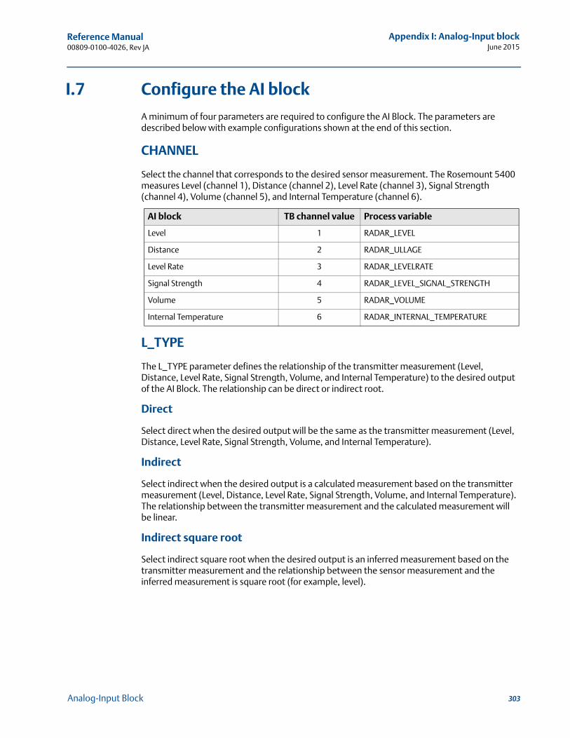
Reference Manual 00809-0100-4026, Rev JA
Appendix I: Analog-Input blockJune 2015
I.7 Configure the AI block
A minimum of four parameters are required to configure the AI Block. The parameters are described below with example configurations shown at the end of this section.
CHANNEL
Select the channel that corresponds to the desired sensor measurement. The Rosemount 5400 measures Level (channel 1), Distance (channel 2), Level Rate (channel 3), Signal Strength (channel 4), Volume (channel 5), and Internal Temperature (channel 6).
L_TYPE
The L_TYPE parameter defines the relationship of the transmitter measurement (Level, Distance, Level Rate, Signal Strength, Volume, and Internal Temperature) to the desired output of the AI Block. The relationship can be direct or indirect root.
Direct
Select direct when the desired output will be the same as the transmitter measurement (Level, Distance, Level Rate, Signal Strength, Volume, and Internal Temperature).
Indirect
Select indirect when the desired output is a calculated measurement based on the transmitter measurement (Level, Distance, Level Rate, Signal Strength, Volume, and Internal Temperature). The relationship between the transmitter measurement and the calculated measurement will be linear.
Indirect square root
Select indirect square root when the desired output is an inferred measurement based on the transmitter measurement and the relationship between the sensor measurement and the inferred measurement is square root (for example, level).
AI block TB channel value Process variable
Level 1 RADAR_LEVEL
Distance 2 RADAR_ULLAGE
Level Rate 3 RADAR_LEVELRATE
Signal Strength 4 RADAR_LEVEL_SIGNAL_STRENGTH
Volume 5 RADAR_VOLUME
Internal Temperature 6 RADAR_INTERNAL_TEMPERATURE
303Analog-Input Block
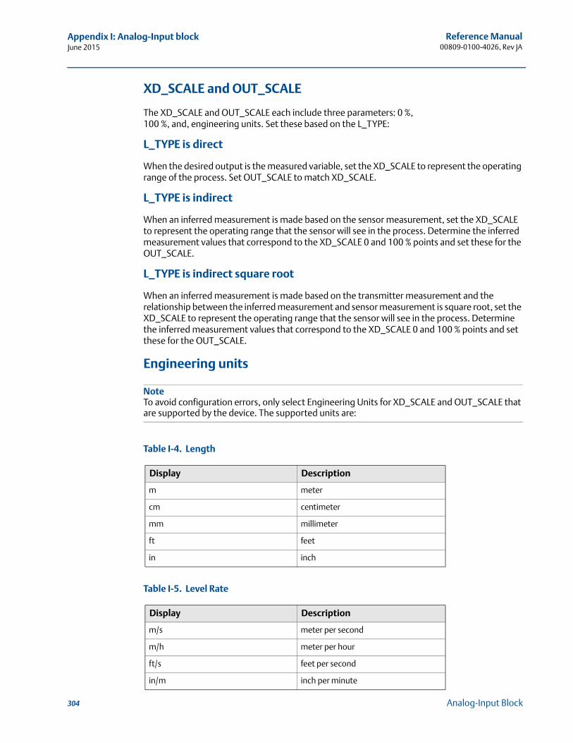
Reference Manual00809-0100-4026, Rev JA
Appendix I: Analog-Input blockJune 2015
XD_SCALE and OUT_SCALE
The XD_SCALE and OUT_SCALE each include three parameters: 0 %, 100 %, and, engineering units. Set these based on the L_TYPE:
L_TYPE is direct
When the desired output is the measured variable, set the XD_SCALE to represent the operating range of the process. Set OUT_SCALE to match XD_SCALE.
L_TYPE is indirect
When an inferred measurement is made based on the sensor measurement, set the XD_SCALE to represent the operating range that the sensor will see in the process. Determine the inferred measurement values that correspond to the XD_SCALE 0 and 100 % points and set these for the OUT_SCALE.
L_TYPE is indirect square root
When an inferred measurement is made based on the transmitter measurement and the relationship between the inferred measurement and sensor measurement is square root, set the XD_SCALE to represent the operating range that the sensor will see in the process. Determine the inferred measurement values that correspond to the XD_SCALE 0 and 100 % points and set these for the OUT_SCALE.
Engineering units
NoteTo avoid configuration errors, only select Engineering Units for XD_SCALE and OUT_SCALE that are supported by the device. The supported units are:
Table I-4. Length
Table I-5. Level Rate
Display Description
m meter
cm centimeter
mm millimeter
ft feet
in inch
Display Description
m/s meter per second
m/h meter per hour
ft/s feet per second
in/m inch per minute
304 Analog-Input Block
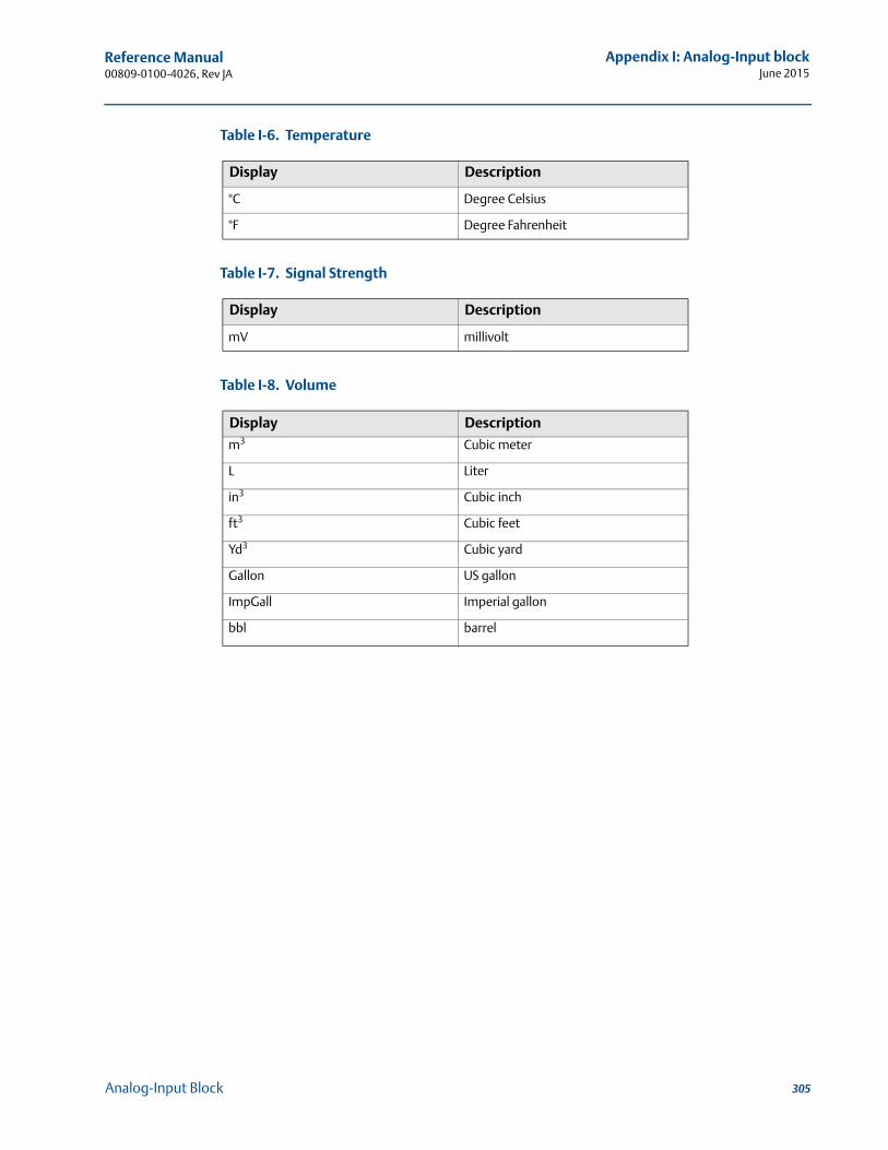
Reference Manual 00809-0100-4026, Rev JA
Appendix I: Analog-Input blockJune 2015
Table I-6. Temperature
Table I-7. Signal Strength
Table I-8. Volume
Display Description
°C Degree Celsius
°F Degree Fahrenheit
Display Description
mV millivolt
Display Description
m3 Cubic meter
L Liter
in3 Cubic inch
ft3 Cubic feet
Yd3 Cubic yard
Gallon US gallon
ImpGall Imperial gallon
bbl barrel
305Analog-Input Block

306
Reference Manual00809-0100-4026, Rev JA
Appendix I: Analog-Input blockJune 2015
Analog-Input Block
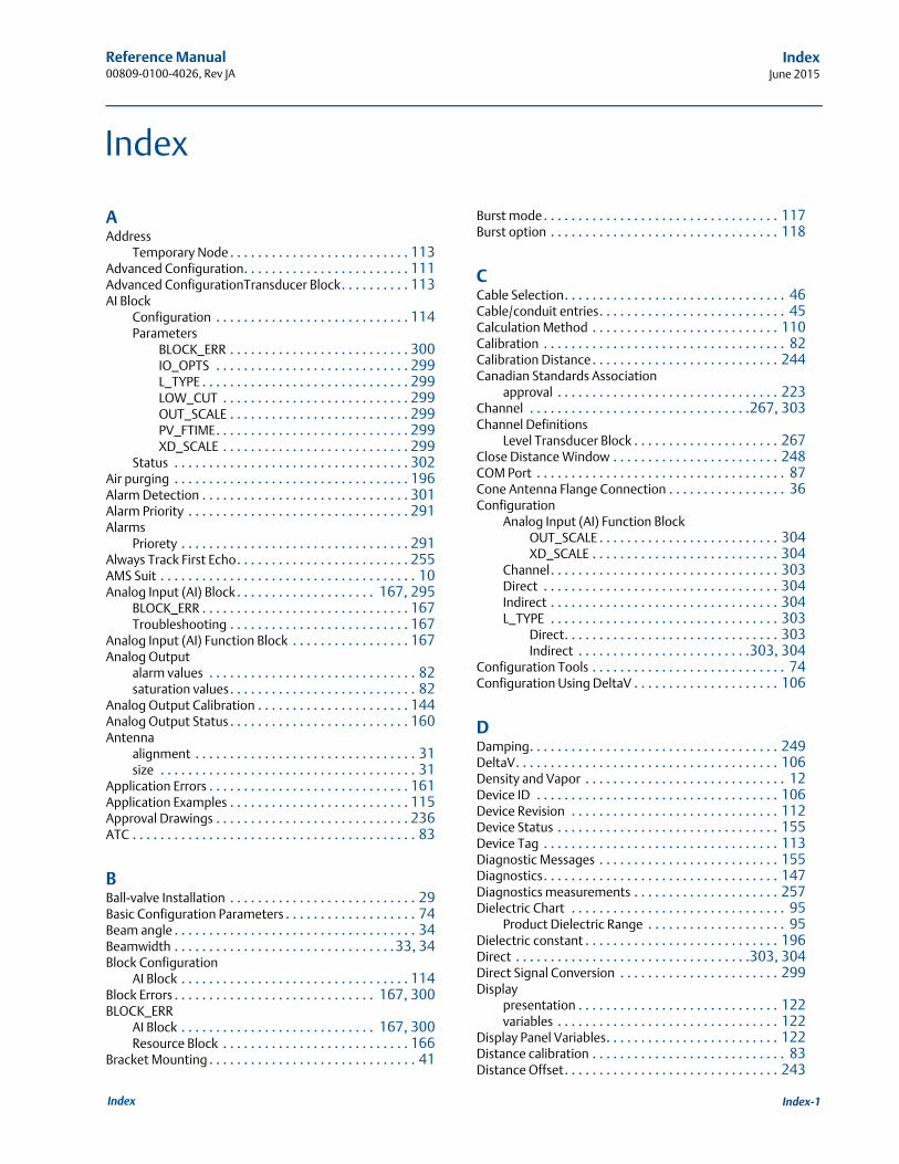
Reference Manual 00809-0100-4026, Rev JA
IndexJune 2015
Index
AAddress
Temporary Node . . . . . . . . . . . . . . . . . . . . . . . . . . 113Advanced Configuration. . . . . . . . . . . . . . . . . . . . . . . . 111Advanced ConfigurationTransducer Block. . . . . . . . . . 113AI Block
Configuration . . . . . . . . . . . . . . . . . . . . . . . . . . . . 114Parameters
BLOCK_ERR . . . . . . . . . . . . . . . . . . . . . . . . . . 300IO_OPTS . . . . . . . . . . . . . . . . . . . . . . . . . . . . 299L_TYPE . . . . . . . . . . . . . . . . . . . . . . . . . . . . . . 299LOW_CUT . . . . . . . . . . . . . . . . . . . . . . . . . . . 299OUT_SCALE . . . . . . . . . . . . . . . . . . . . . . . . . . 299PV_FTIME. . . . . . . . . . . . . . . . . . . . . . . . . . . . 299XD_SCALE . . . . . . . . . . . . . . . . . . . . . . . . . . . 299
Status . . . . . . . . . . . . . . . . . . . . . . . . . . . . . . . . . . 302Air purging . . . . . . . . . . . . . . . . . . . . . . . . . . . . . . . . . . 196Alarm Detection . . . . . . . . . . . . . . . . . . . . . . . . . . . . . . 301Alarm Priority . . . . . . . . . . . . . . . . . . . . . . . . . . . . . . . . 291Alarms
Priorety . . . . . . . . . . . . . . . . . . . . . . . . . . . . . . . . . 291Always Track First Echo. . . . . . . . . . . . . . . . . . . . . . . . . 255AMS Suit . . . . . . . . . . . . . . . . . . . . . . . . . . . . . . . . . . . . . 10Analog Input (AI) Block . . . . . . . . . . . . . . . . . . . . 167, 295
BLOCK_ERR . . . . . . . . . . . . . . . . . . . . . . . . . . . . . . 167Troubleshooting . . . . . . . . . . . . . . . . . . . . . . . . . . 167
Analog Input (AI) Function Block . . . . . . . . . . . . . . . . . 167Analog Output
alarm values . . . . . . . . . . . . . . . . . . . . . . . . . . . . . . 82saturation values. . . . . . . . . . . . . . . . . . . . . . . . . . . 82
Analog Output Calibration . . . . . . . . . . . . . . . . . . . . . . 144Analog Output Status . . . . . . . . . . . . . . . . . . . . . . . . . . 160Antenna
alignment . . . . . . . . . . . . . . . . . . . . . . . . . . . . . . . . 31size . . . . . . . . . . . . . . . . . . . . . . . . . . . . . . . . . . . . . 31
Application Errors . . . . . . . . . . . . . . . . . . . . . . . . . . . . . 161Application Examples . . . . . . . . . . . . . . . . . . . . . . . . . . 115Approval Drawings . . . . . . . . . . . . . . . . . . . . . . . . . . . . 236ATC . . . . . . . . . . . . . . . . . . . . . . . . . . . . . . . . . . . . . . . . . 83
BBall-valve Installation . . . . . . . . . . . . . . . . . . . . . . . . . . . 29Basic Configuration Parameters . . . . . . . . . . . . . . . . . . . 74Beam angle . . . . . . . . . . . . . . . . . . . . . . . . . . . . . . . . . . . 34Beamwidth . . . . . . . . . . . . . . . . . . . . . . . . . . . . . . . .33, 34Block Configuration
AI Block . . . . . . . . . . . . . . . . . . . . . . . . . . . . . . . . . 114Block Errors . . . . . . . . . . . . . . . . . . . . . . . . . . . . . 167, 300BLOCK_ERR
AI Block . . . . . . . . . . . . . . . . . . . . . . . . . . . . 167, 300Resource Block . . . . . . . . . . . . . . . . . . . . . . . . . . . 166
Bracket Mounting . . . . . . . . . . . . . . . . . . . . . . . . . . . . . . 41
Burst mode . . . . . . . . . . . . . . . . . . . . . . . . . . . . . . . . . . 117Burst option . . . . . . . . . . . . . . . . . . . . . . . . . . . . . . . . . 118
CCable Selection. . . . . . . . . . . . . . . . . . . . . . . . . . . . . . . . 46Cable/conduit entries. . . . . . . . . . . . . . . . . . . . . . . . . . . 45Calculation Method . . . . . . . . . . . . . . . . . . . . . . . . . . . 110Calibration . . . . . . . . . . . . . . . . . . . . . . . . . . . . . . . . . . . 82Calibration Distance. . . . . . . . . . . . . . . . . . . . . . . . . . . 244Canadian Standards Association
approval . . . . . . . . . . . . . . . . . . . . . . . . . . . . . . . . 223Channel . . . . . . . . . . . . . . . . . . . . . . . . . . . . . . . .267, 303Channel Definitions
Level Transducer Block . . . . . . . . . . . . . . . . . . . . . 267Close Distance Window . . . . . . . . . . . . . . . . . . . . . . . . 248COM Port . . . . . . . . . . . . . . . . . . . . . . . . . . . . . . . . . . . . 87Cone Antenna Flange Connection . . . . . . . . . . . . . . . . . 36Configuration
Analog Input (AI) Function BlockOUT_SCALE . . . . . . . . . . . . . . . . . . . . . . . . . . 304XD_SCALE . . . . . . . . . . . . . . . . . . . . . . . . . . . 304
Channel. . . . . . . . . . . . . . . . . . . . . . . . . . . . . . . . . 303Direct . . . . . . . . . . . . . . . . . . . . . . . . . . . . . . . . . . 304Indirect . . . . . . . . . . . . . . . . . . . . . . . . . . . . . . . . . 304L_TYPE . . . . . . . . . . . . . . . . . . . . . . . . . . . . . . . . . 303
Direct. . . . . . . . . . . . . . . . . . . . . . . . . . . . . . . 303Indirect . . . . . . . . . . . . . . . . . . . . . . . . .303, 304
Configuration Tools . . . . . . . . . . . . . . . . . . . . . . . . . . . . 74Configuration Using DeltaV . . . . . . . . . . . . . . . . . . . . . 106
DDamping. . . . . . . . . . . . . . . . . . . . . . . . . . . . . . . . . . . . 249DeltaV. . . . . . . . . . . . . . . . . . . . . . . . . . . . . . . . . . . . . . 106Density and Vapor . . . . . . . . . . . . . . . . . . . . . . . . . . . . . 12Device ID . . . . . . . . . . . . . . . . . . . . . . . . . . . . . . . . . . . 106Device Revision . . . . . . . . . . . . . . . . . . . . . . . . . . . . . . 112Device Status . . . . . . . . . . . . . . . . . . . . . . . . . . . . . . . . 155Device Tag . . . . . . . . . . . . . . . . . . . . . . . . . . . . . . . . . . 113Diagnostic Messages . . . . . . . . . . . . . . . . . . . . . . . . . . 155Diagnostics. . . . . . . . . . . . . . . . . . . . . . . . . . . . . . . . . . 147Diagnostics measurements . . . . . . . . . . . . . . . . . . . . . 257Dielectric Chart . . . . . . . . . . . . . . . . . . . . . . . . . . . . . . . 95
Product Dielectric Range . . . . . . . . . . . . . . . . . . . . 95Dielectric constant . . . . . . . . . . . . . . . . . . . . . . . . . . . . 196Direct . . . . . . . . . . . . . . . . . . . . . . . . . . . . . . . . . .303, 304Direct Signal Conversion . . . . . . . . . . . . . . . . . . . . . . . 299Display
presentation . . . . . . . . . . . . . . . . . . . . . . . . . . . . . 122variables . . . . . . . . . . . . . . . . . . . . . . . . . . . . . . . . 122
Display Panel Variables. . . . . . . . . . . . . . . . . . . . . . . . . 122Distance calibration . . . . . . . . . . . . . . . . . . . . . . . . . . . . 83Distance Offset. . . . . . . . . . . . . . . . . . . . . . . . . . . . . . . 243
Index-1Index
Reference Manual00809-0100-4026, Rev JA
IndexJune 2015
Disturbing objects . . . . . . . . . . . . . . . . . . . . . . . . . . . . . 35Double Bounce . . . . . . . . . . . . . . . . . . . . . . . . . . . . . . . 247Double Surface . . . . . . . . . . . . . . . . . . . . . . . . . . . . . . . 248Draft Range. . . . . . . . . . . . . . . . . . . . . . . . . . . . . . . . . . . . 4
EEcho Curve Analyzer . . . . . . . . . . . . . . . . . . . . . . . . . . . 142Echo Timeout . . . . . . . . . . . . . . . . . . . . . . . . . . . . . . . . 248Echo Tuning . . . . . . . . . . . . . . . . . . . . . . . . . . . . . . . . . . 83Electrical installation
connecting the transmitter. . . . . . . . . . . . . . . . . . . 51Intrinsically Safe Output . . . . . . . . . . . . . . . . . .52, 58Non-Intrinsically Safe Output . . . . . . . . . . . . . . . . . 51Tri-Loop . . . . . . . . . . . . . . . . . . . . . . . . . . . . . . .69, 70
Empty Tank Detection Area . . . . . . . . . . . . . . . . . . . . . 246Empty Tank Handling . . . . . . . . . . . . . . . . . . . . . . . . . . 245Error messages . . . . . . . . . . . . . . . . . . . . . . . . . . . . . . . 156Errors. . . . . . . . . . . . . . . . . . . . . . . . . . . . . . . . . . . . . . . 156Extended Cone Antenna. . . . . . . . . . . . . . . . . . . . . . . . . 30External circuit breaker. . . . . . . . . . . . . . . . . . . . . . . . . . 47External HART Devices . . . . . . . . . . . . . . . . . . . . . . . . . . 65
FFactory Mutual
approval . . . . . . . . . . . . . . . . . . . . . . . . . . . . . . . . 222False Echo . . . . . . . . . . . . . . . . . . . . . . . . . . . . . . . . . . . 134False Echo Area . . . . . . . . . . . . . . . . . . . . . . . . . . . . . . . 135False Echo Registration. . . . . . . . . . . . . . . . . . . . . . . . . 111False echoes . . . . . . . . . . . . . . . . . . . . . . . . . . . . . . . . . . 35Features . . . . . . . . . . . . . . . . . . . . . . . . . . . . . . . . . . . . . . 4Field Communicator . . . . . . . . . . . . . . . . . . . . . . . .10, 101Filtering
AI Block . . . . . . . . . . . . . . . . . . . . . . . . . . . . . . . . . 299Full Tank Detection Area . . . . . . . . . . . . . . . . . . . . . . . 247Full Tank Handling . . . . . . . . . . . . . . . . . . . . . . . . . . . . 253Function blocks. . . . . . . . . . . . . . . . . . . . . . . . . . . . . . . 113
GGrounding. . . . . . . . . . . . . . . . . . . . . . . . . . . . . . . . . . . . 46
HHART Multidrop Configuration. . . . . . . . . . . . . . . . . . . 119HART to Modbus Converter (HMC) . . . . . . . . . . . . . . . . 60Hazardous Areas . . . . . . . . . . . . . . . . . . . . . . . . . . . . . . . 47Hazardous Locations Certifications . . . . . . . . . . . . . . . 222Hold Off Distance . . . . . . 134, 135, 244, 245, 247, 253
IInclination . . . . . . . . . . . . . . . . . . . . . . . . . . . . . . . . . . . . 32Indirect . . . . . . . . . . . . . . . . . . . . . . . . . . . . . . . . 303, 304Indirect Signal Conversion . . . . . . . . . . . . . . . . . . . . . . 299
Installationcable selection . . . . . . . . . . . . . . . . . . . . . . . . . . . . 46cable/conduit entries . . . . . . . . . . . . . . . . . . . . . . . 45grounding . . . . . . . . . . . . . . . . . . . . . . . . . . . . . . . . 46power requirements. . . . . . . . . . . . . . . . . . . . . . . . 49Service Space . . . . . . . . . . . . . . . . . . . . . . . . . . . . . 32
Introduction . . . . . . . . . . . . . . . . . . . . . . . . . . . . . . . . . . . 1IO_OPTS
AI Block . . . . . . . . . . . . . . . . . . . . . . . . . . . . . . . . . 299
LL_TYPE . . . . . . . . . . . . . . . . . . . . . . . . . . . . . . . . . . . . . 303
. . . . . . . . . . . . . . . . . . . . . . . . . . . . . . . . . . .303, 304AI Block . . . . . . . . . . . . . . . . . . . . . . . . . . . . . . . . . 299
LCD . . . . . . . . . . . . . . . . . . . . . . . . . . . . . . . . . . . .100, 122Parameters . . . . . . . . . . . . . . . . . . . . . . . . . . . . . . 125
LCD Error Messages . . . . . . . . . . . . . . . . . . . . . . . . . . . 128LCD Parameters . . . . . . . . . . . . . . . . . . . . . . . . . . . . . . 125LCD variables . . . . . . . . . . . . . . . . . . . . . . . . . . . . . . . . . 91LED Error Messages . . . . . . . . . . . . . . . . . . . . . . . . . . . 129Level . . . . . . . . . . . . . . . . . . . . . . . . . . . . . . . . . . . . . . . . . 7Level calibration . . . . . . . . . . . . . . . . . . . . . . . . . . . . . . . 83Level Transducer Block. . . . . . . . . . . . . . . . . . . . . . . . . 113
Channel Definitions . . . . . . . . . . . . . . . . . . . . . . . 267Level Transducer Block Parameters . . . . . . . . . . . . . . . 268Logging Measurement Data . . . . . . . . . . . . . . . . . . . . 145Loop-powered . . . . . . . . . . . . . . . . . . . . . . . . . . . . . . . . 10LOW_CUT. . . . . . . . . . . . . . . . . . . . . . . . . . . . . . . . . . . 299
AI Block . . . . . . . . . . . . . . . . . . . . . . . . . . . . . . . . . 299Lower Reference Point . . . . . . . . . . . . . . . . . . . . . . . . . . 75
MManual
Models covered . . . . . . . . . . . . . . . . . . . . . . . . . . . . 4Maximum load resistance . . . . . . . . . . . . . . . . . . . . . . . 52Measure and Learn function. . . . . . . . . . . . . . . . . . . . . . 83Measurement Status . . . . . . . . . . . . . . . . . . . . . . . . . . 157Measurement Units . . . . . . . . . . . . . . . . . . . . . . . . . . . . 75Measuring Range . . . . . . . . . . . . . . . . . . . . . . . . . .15, 196minifast . . . . . . . . . . . . . . . . . . . . . . . . . . . . . . . . . . . . . 45Minimum Level Offset . . . . . . . . . . . . . . . . . . . . . . . . . 244Mounting
Bracket Mounting . . . . . . . . . . . . . . . . . . . . . . . 41, 42Process Seal . . . . . . . . . . . . . . . . . . . . . . . . . . . . . . 37Rod . . . . . . . . . . . . . . . . . . . . . . . . . . . . . . . . . . . . . 39Standard Cone . . . . . . . . . . . . . . . . . . . . . . . . . . . . 36
Mounting requirements. . . . . . . . . . . . . . . . . . . . . . . . . 22Multidrop connection . . . . . . . . . . . . . . . . . . . . . . . . . 119Multidrop Mode . . . . . . . . . . . . . . . . . . . . . . . . . . . . . . 119
NNAMUR-Compliant Alarm . . . . . . . . . . . . . . . . . . . . . . . 82Node Address . . . . . . . . . . . . . . . . . . . . . . . . . . . . . . . . 113Nozzle recommendation . . . . . . . . . . . . . . . . . . . . . . . . 30
Index-2 Index
Reference Manual 00809-0100-4026, Rev JA
IndexJune 2015
OOperation . . . . . . . . . . . . . . . . . . . . . . . . . . . . . . . . . . . 112Optional Devices. . . . . . . . . . . . . . . . . . . . . . . . . . . . . . . 69OSHA . . . . . . . . . . . . . . . . . . . . . . . . . . . . . . . . . . . . . . . . 3OUT_SCALE. . . . . . . . . . . . . . . . . . . . . . . . . . . . . . . . . . 304
AI Block . . . . . . . . . . . . . . . . . . . . . . . . . . . . . . . . . 299L_TYPE
Direct . . . . . . . . . . . . . . . . . . . . . . . . . . . . . . . 304Indirect . . . . . . . . . . . . . . . . . . . . . . . . . . . . . 304
PParameter
BLOCK_ERR . . . . . . . . . . . . . . . . . . . . . . . . . 166, 167CHANNEL . . . . . . . . . . . . . . . . . . . . . . . . . . . . . . . 303L_TYPE. . . . . . . . . . . . . . . . . . . . . . . . . . . . . 303, 304OUT_SCALE . . . . . . . . . . . . . . . . . . . . . . . . . . . . . . 304Resource Block . . . . . . . . . . . . . . . . . . . . . . . . . . . 283XD_SCALE . . . . . . . . . . . . . . . . . . . . . . . . . . . . . . . 304
Percent of Range . . . . . . . . . . . . . . . . . . . . . . . . . . . . . 188Performing Proof Test . . . . . . . . . . . . . . . . . . . . . . . . . 261Poll address. . . . . . . . . . . . . . . . . . . . . . . . . . . . . . . . . . 119Power Requirements . . . . . . . . . . . . . . . . . . . . . . . . . . . 49Pressure . . . . . . . . . . . . . . . . . . . . . . . . . . . . . . . . . . . . . 12Process Conditions . . . . . . . . . . . . . . . . . . . . . . . . . . . . . 77Process Seal Antenna . . . . . . . . . . . . . . . . . . . . . . . . . . . 37Product Certifcates. . . . . . . . . . . . . . . . . . . . . . . . . . . . 219Product Dielectric Range . . . . . . . . . . . . . . . . . . . . . . . . 95Product Level . . . . . . . . . . . . . . . . . . . . . . . . . . . . . . . . . 75Product surface. . . . . . . . . . . . . . . . . . . . . . . . . . . . . . . 134Purging connection . . . . . . . . . . . . . . . . . . . . . . 196, 202PV_FTIME
AI Block . . . . . . . . . . . . . . . . . . . . . . . . . . . . . . . . . 299
RReference pulse . . . . . . . . . . . . . . . . . . . . . . . . . . . . . . 134Register Transducer Block . . . . . . . . . . . . . . . . . . . . . . 113Resource Block . . . . . . . . . . . . . . . . . . . . . . 114, 166, 283
Block Errors . . . . . . . . . . . . . . . . . . . . . . . . . . . . . . 166Detailed Status . . . . . . . . . . . . . . . . . . . . . . . . . . . 166Parameters . . . . . . . . . . . . . . . . . . . . . . . . . . . . . . 283
BLOCK_ERR . . . . . . . . . . . . . . . . . . . . . . . . . . 166PlantWeb Alerts . . . . . . . . . . . . . . . . . . . . . . . . . . 288
Recommended Actions. . . . . . . . . . . . . . . . . 292PlantWeb™ Alerts
advisory alarms . . . . . . . . . . . . . . . . . . . . . . . 290failed_alarms . . . . . . . . . . . . . . . . . . . . . . . . . 288maint_alarms . . . . . . . . . . . . . . . . . . . . . . . . 289
Summary Status . . . . . . . . . . . . . . . . . . . . . . . . . . 166Resource block . . . . . . . . . . . . . . . . . . . . . . . . . . . . . . . 113Rod Antenna Flanged Connection . . . . . . . . . . . . . . . . . 39Rod Antenna Threaded Connection . . . . . . . . . . . . . . . . 38Rosemount 751 . . . . . . . . . . . . . . . . . . . . . . . . . . . . . . . 10RRM. . . . . . . . . . . . . . . . . . . . . . . . . . . . . . . . . . . . . . . . . 84
COM Port. . . . . . . . . . . . . . . . . . . . . . . . . . . . . . . . . 87Setup . . . . . . . . . . . . . . . . . . . . . . . . . . . . . . . .91, 100
RS-485 Bus . . . . . . . . . . . . . . . . . . . . . . . . . . . . . . . . . . . 63
SSaturation Mode. . . . . . . . . . . . . . . . . . . . . . . . . . . . . . . 81Select Lower Surface . . . . . . . . . . . . . . . . . . . . . . . . . . 248Service space recommendations . . . . . . . . . . . . . . . . . . 32Service Support . . . . . . . . . . . . . . . . . . . . . . . . . . . . . . . . 3Signal Conversion
Direct . . . . . . . . . . . . . . . . . . . . . . . . . . . . . . . . . . 299Indirect . . . . . . . . . . . . . . . . . . . . . . . . . . . . . . . . . 299
Signal Quality Metrics. . . . . . . . . . . . . . . . . . . . . .188, 257Simulation . . . . . . . . . . . . . . . . . . . . . . . . . . . . . . . . . . 298Slaves . . . . . . . . . . . . . . . . . . . . . . . . . . . . . . . . . . . . . . . 65Slow Search . . . . . . . . . . . . . . . . . . . . . . . . . . . . . . . . . 248Slow Search Speed . . . . . . . . . . . . . . . . . . . . . . . . . . . . 248Smart Wireless THUM Adapter . . . . . . . . . . . . . . . . . . . 71Solid product . . . . . . . . . . . . . . . . . . . . . . . . . . . . . . . . . 77Solids applications . . . . . . . . . . . . . . . . . . 12, 13, 24, 196SQM . . . . . . . . . . . . . . . . . . . . . . . . . . . . . . . . . . .188, 257Standard Tank Shapes . . . . . . . . . . . . . . . . . . . . . . . . . . 79Status
AI Block . . . . . . . . . . . . . . . . . . . . . . . . . . . . . . . . . 302Still-pipes in Metallic Materials. . . . . . . . . . . . . . . . . . . . 28Strapping Table . . . . . . . . . . . . . . . . . . . . . . . . . . .80, 110Support. . . . . . . . . . . . . . . . . . . . . . . . . . . . . . . . . . . . . . . 3Supported Units . . . . . . . . . . . . . . . . . . . . . . . . . . . . . . 304Surface Echo Tracking . . . . . . . . . . . . . . . . . . . . . . . . . 255Surface Threshold . . . . . . . . . . . . . . . . . . . . . . . . . . . . 134Surface/Noise Margin. . . . . . . . . . . . . . . . . . . . . .188, 257
TTag
Device . . . . . . . . . . . . . . . . . . . . . . . . . . . . . . . . . . 113Tank Bottom. . . . . . . . . . . . . . . . . . . . . . . . . . . . . . . . . 135Tank Bottom Type . . . . . . . . . . . . . . . . . . . . . . . . . . . . . 76Tank Geometry. . . . . . . . . . . . . . . . . . . . . . . . . . . .75, 243Tank height . . . . . . . . . . . . . . . . . . . . . . . . . . . . . . . . . . . 7Tank Seal . . . . . . . . . . . . . . . . . . . . . . . . . . . . . . . . . . . . 14Tank Type . . . . . . . . . . . . . . . . . . . . . . . . . . . . . . . . . . . . 76Tightening torque for Process Seal flanges . . . . . . . . . . 38Transducer block . . . . . . . . . . . . . . . . . . . . . . . . . . . . . 113Transition Zone . . . . . . . . . . . . . . . . . . . . . . . . . . .75, 196Transmitter head . . . . . . . . . . . . . . . . . . . . . . . . . . . . . . 14Tri Clamp connection . . . . . . . . . . . . . . . . . . . . . . .40, 204Tri-Loop . . . . . . . . . . . . . . . . . . . . . . . . . . . . . . . . .69, 117Troubleshooting. . . . . . . . . . . . . . . . . . . . . . . . . .155, 165
Analog Input (AI) Block . . . . . . . . . . . . . . . . . . . . . 167Resource Block . . . . . . . . . . . . . . . . . . . . . . . . . . . 166
Troubleshooting chart . . . . . . . . . . . . . . . . . . . . . . . . . 133
UUpper Null Zone . . . . . . . . . . . . . . . . . . . . . . . . . .134, 135Upper Product Dielectric Constant . . . . . . . . . . . . . . . 248Upper Reference Point . . . . . . . . . . . . . . . . . . . . . . . 75, 76
VValves . . . . . . . . . . . . . . . . . . . . . . . . . . . . . . . . . . . . . . . 35
Index-3Index
Reference Manual00809-0100-4026, Rev JA
IndexJune 2015
Vessel Characteristics . . . . . . . . . . . . . . . . . . . . . . . . . . . 35Volume Calculation Status . . . . . . . . . . . . . . . . . . . . . . 159Volume Configuration . . . . . . . . . . . . . . . . . . . . . . . . . . 78
Strapping Table. . . . . . . . . . . . . . . . . . . . . . . . . . . . 80Volume Offset . . . . . . . . . . . . . . . . . . . . . . . . . . . . . 78
Volume Offset. . . . . . . . . . . . . . . . . . . . . . . . . . . . . . . . 110
WWarnings. . . . . . . . . . . . . . . . . . . . . . . . . . . . . . . . . . . . 157
XXD_SCALE . . . . . . . . . . . . . . . . . . . . . . . . . . . . . . . . . . . 304
AI Block . . . . . . . . . . . . . . . . . . . . . . . . . . . . . . . . . 299L_TYPE
Direct . . . . . . . . . . . . . . . . . . . . . . . . . . . . . . . 304Indirect . . . . . . . . . . . . . . . . . . . . . . . . . . . . . 304
Index-4 Index


Reference Manual00809-0100-4026, Rev JA
2015
Global Headquarters
Emerson Process Management 6021 Innovation BlvdShakopee, MN 55379, USA+1 800 999 9307 or +1 952 906 8888+1 952 949 7001 [email protected]
North America Regional OfficeEmerson Process Management 8200 Market Blvd.Chanhassen, MN 55317, USA
+1 800 999 9307 or +1 952 906 8888+1 952 949 7001 [email protected]
Latin America Regional OfficeEmerson Process Management 1300 Concord Terrace, Suite 400Sunrise, Florida, 33323, USA
+1 954 846 5030+1 954 846 [email protected]
Europe Regional OfficeEmerson Process Management Europe GmbHNeuhofstrasse 19a P.O. Box 1046CH 6340 BaarSwitzerland
+41 (0) 41 768 6111+41 (0) 41 768 6300 [email protected]
Asia Pacific Regional OfficeEmerson Process Management Asia Pacific Pte Ltd1 Pandan CrescentSingapore 128461
+65 6777 8211+65 6777 0947 [email protected]
Middle East and Africa Regional OfficeEmerson Process Management Emerson FZE P.O. Box 17033,Jebel Ali Free Zone - South 2Dubai, United Arab Emirates
+971 4 8118100+971 4 8865465 [email protected]
Standard Terms and Conditions of Sale can be found at: www.rosemount.com/terms_of_sale.The Emerson logo is a trademark and service mark of Emerson Electric Co.AMS, PlantWeb, Rosemount, and the Rosemount logotype are registered trademarks of Rosemount Inc.DeltaV, THUM and Tri-Loop are trademarks of Rosemount Inc.HART and WirelessHART are registered trademarks of the FieldComm Group.FOUNDATION fieldbus is a trademark of the FieldComm Group.Modbus is a registered trademark of Modicon, Inc.Viton and Kalrez are registered trademarks of DuPont Performance Elastomers.eurofast and minifast are registered trademarks of TURCK.Microsoft is a registered trademark of Microsoft Corporation in the United States and other countries.Windows is a trademark of Microsoft Corporation in the United States and other countries.FDT is a registered trademark of the FDT group.DTM is a trademark of the FDT group.PACTware is a trademark of PACTware Consortium.NACE is a registered trademark of NACE International.FieldCare is a trademark of Endress + Hauser AG.All other marks are the property of their respective owners.© 2015 Rosemount Inc. All rights reserved.