Embed Size (px)
Citation preview
ROSEMONT PROJECT
MINE PLAN OF OPERATIONS
Prepared for:
AUGUSTA RESOURCE CORPORATION 4500 Cherry Creek South Drive, Suite 1040
Denver, Colorado 80246
Prepared by:
WESTLAND RESOURCES, INC. 2343 E. Broadway Boulevard, Suite 202
Tucson, Arizona 85719
July 11, 2007 Project No. 1049.05 B 700
Rosemont Project Mine Plan of Operations
WestLand Resources, Inc. Engineering and Environmental Consultants Q:\Jobs\1000's\1049.05\2007 MPO\Final MPO 070907.doc
ii
TABLE OF CONTENTS Executive Summary 1 Introduction........................................................................................................................................... 1
1.1 Owner and Operator......................................................................................................................... 1 1.2 Project Location, Access, and Areas of Operation .......................................................................... 1 1.3 Mining and Exploration Background............................................................................................... 2 1.4 Physiographic Setting ...................................................................................................................... 2
1.4.1 Climate .................................................................................................................................... 2 1.4.2 Geology ................................................................................................................................... 3 1.4.3 Seismicity................................................................................................................................ 4 1.4.4 Hydrology ............................................................................................................................... 5
1.5 Local Community ............................................................................................................................ 7 1.5.1 Population Demographics ....................................................................................................... 7 1.5.2 Significant Employers ............................................................................................................. 8
2 Project Plan ........................................................................................................................................... 9 2.1 Mine Plan....................................................................................................................................... 10
2.1.1 Open Pit Plans ....................................................................................................................... 10 2.1.2 Mine Haul Roads................................................................................................................... 10 2.1.3 Pit Production Schedule ........................................................................................................11 2.1.4 Blasting ................................................................................................................................. 12 2.1.5 Ore Transport ........................................................................................................................ 13 2.1.6 Waste Rock ........................................................................................................................... 14 2.1.7 Mine Equipment.................................................................................................................... 14 2.1.8 Mine Staffing ........................................................................................................................ 16
2.2 Ore Processing ............................................................................................................................... 17 2.2.1 Process Operations Overview ............................................................................................... 17 2.2.2 Sulfide Ore Processing .......................................................................................................... 18 2.2.3 Oxide Processing................................................................................................................... 21 2.2.4 Water System ........................................................................................................................ 22
2.3 Waste Rock and Mill Tailings Management.................................................................................. 23 2.3.1 Tailings and Waste Rock Characterization ........................................................................... 23 2.3.2 Waste Rock Management Strategy ....................................................................................... 23 2.3.3 Tailings Dry-Stack Facility Design....................................................................................... 26 2.3.4 ARD Monitoring ................................................................................................................... 28
2.4 Ancillary Facilities......................................................................................................................... 30 2.4.1 Administration Building........................................................................................................ 30 2.4.2 Change House ....................................................................................................................... 30 2.4.3 Warehouse............................................................................................................................. 30 2.4.4 Analytical Laboratory ........................................................................................................... 30 2.4.5 Light Vehicle Repair Building and Fuel Storage .................................................................. 31
Rosemont Project Mine Plan of Operations
WestLand Resources, Inc. Engineering and Environmental Consultants Q:\Jobs\1000's\1049.05\2007 MPO\Final MPO 070907.doc
iii
2.4.6 Mine Truck Shop and Fuel Storage....................................................................................... 31 2.4.7 Mine Truck Wash and Lube Facilities .................................................................................. 32 2.4.8 Powder Magazines and Ammonium Nitrate Silos ................................................................ 32 2.4.9 Main Guard House and Truck Scale ..................................................................................... 33
2.5 Staffing........................................................................................................................................... 34 2.6 Access Roads ................................................................................................................................. 36 2.7 Electrical Power Supply................................................................................................................. 38
2.7.1 Interconnection with TEP Line Serving Santa Cruz County (Option 1)............................... 38 2.7.2 Interconnection with SWTC Sahuarita 230 kV Substation (Option 2) ................................. 39 2.7.3 Interconnection with TEP South 345/138 kV Substation (Option 3).................................... 39 2.7.4 Interconnect the TEP South Line to the TEP Vail-Kantor Line (Option 4) .......................... 39 2.7.5 Preliminary Power Flow Analysis......................................................................................... 40 2.7.6 Description of Proposed Electrical Power Supply ................................................................ 40
2.8 Water Supply ................................................................................................................................. 42 2.8.1 Introduction ........................................................................................................................... 42 2.8.2 Legal and Regulatory Considerations ................................................................................... 42 2.8.3 Production Plan ..................................................................................................................... 43 2.8.4 Delivery System.................................................................................................................... 44 2.8.5 Recharge Plan........................................................................................................................ 45
2.9 Surface Water Management........................................................................................................... 46 2.9.1 Closed Systems ..................................................................................................................... 46 2.9.2 Dry Tailings Facility ............................................................................................................. 47 2.9.3 Waste Rock Facility .............................................................................................................. 47 2.9.4 Diversions ............................................................................................................................. 48 2.9.5 Compliance Point Dam ......................................................................................................... 49
2.10 Transportation................................................................................................................................ 50 2.10.1 Copper and Molybdenum Concentrates............................................................................ 50 2.10.2 Sulfuric Acid..................................................................................................................... 51 2.10.3 Pebble Lime ...................................................................................................................... 51 2.10.4 SAG and Ball Mill Grinding Balls.................................................................................... 51 2.10.5 Diesel Fuel ........................................................................................................................ 51 2.10.6 Copper Cathodes............................................................................................................... 52 2.10.7 Ammonium Nitrate ........................................................................................................... 52 2.10.8 Miscellaneous Consumables............................................................................................. 52 2.10.9 Miscellaneous Fuels and Lubricants................................................................................. 53 2.10.10 Employees......................................................................................................................... 53 2.10.11 Safety Evaluation.............................................................................................................. 53
2.11 Waste Management........................................................................................................................ 54 2.11.1 On-Site Management of Wastes ....................................................................................... 54 2.11.2 Offsite Shipment of Wastes .............................................................................................. 57
2.12 Construction Phase ........................................................................................................................ 58
Rosemont Project Mine Plan of Operations
WestLand Resources, Inc. Engineering and Environmental Consultants Q:\Jobs\1000's\1049.05\2007 MPO\Final MPO 070907.doc
iv
2.12.1 Transportation................................................................................................................... 58 2.12.2 Personnel........................................................................................................................... 58 2.12.3 Major Equipment .............................................................................................................. 59 2.12.4 Electrical Equipment & Materials .................................................................................... 62 2.12.5 Construction Materials...................................................................................................... 62 2.12.6 Fuels and Lubricants ......................................................................................................... 63 2.12.7 Summary........................................................................................................................... 63
2.13 Site Operations Security and Public Safety ................................................................................... 64 2.13.1 Security ............................................................................................................................. 64 2.13.2 Public Safety ..................................................................................................................... 64 2.13.3 Fire and Emergency Planning........................................................................................... 64
3 Resource Protection and Control Plans............................................................................................... 67 3.1 Groundwater Protection Plan......................................................................................................... 67
3.1.1 Potentially Discharging Facilities ......................................................................................... 67 3.1.2 Pollutant Management Area (PMA) ..................................................................................... 70
3.2 Air Quality and Dust Control Plan................................................................................................. 72 3.2.1 Air Quality Permitting........................................................................................................... 72 3.2.2 Dust Control Measures.......................................................................................................... 74
3.3 Reclamation and Closure ............................................................................................................... 76 3.3.1 General .................................................................................................................................. 76 3.3.2 Closure Concepts .................................................................................................................. 76 3.3.3 Post-Closure Land Uses ........................................................................................................ 77 3.3.4 Concurrent Reclamation Design ........................................................................................... 77 3.3.5 Operating Considerations...................................................................................................... 78
3.4 Viewshed Protection Plan .............................................................................................................. 79 3.5 Public Access and Recreation Mitigation Plan .............................................................................. 80
3.5.1 Access to Public Lands ......................................................................................................... 80 3.5.2 Recreation Diversity.............................................................................................................. 83
3.6 Biological Resource Plan............................................................................................................... 88 3.6.1 Vegetation and Habitat Description ...................................................................................... 88 3.6.2 Special Status Species ........................................................................................................... 88 3.6.3 Noxious Weeds ..................................................................................................................... 89 3.6.4 Pima County Conservation Lands System ............................................................................ 90
3.7 Cultural Resource Plan .................................................................................................................. 91 3.8 Lighting Plan.................................................................................................................................. 92
3.8.1 Property Site Outdoor Light Output Limits .......................................................................... 92 3.8.2 Lamp Type and Shielding Standards .................................................................................... 93 3.8.3 Miscellaneous OLC Items..................................................................................................... 93 3.8.4 Proposed Rosemont Mine Outdoor Lighting Design Specification ...................................... 94
References................................................................................................................................................... 95
Rosemont Project Mine Plan of Operations
WestLand Resources, Inc. Engineering and Environmental Consultants Q:\Jobs\1000's\1049.05\2007 MPO\Final MPO 070907.doc
v
LIST OF TABLES
Table 1. Anticipated Project Disturbance ..................................................................................................... 9 Table 2. Rosemont Copper Project Production Schedule ........................................................................... 12 Table 3. Major Mining Equipment ............................................................................................................. 15 Table 4. Mill Reagents ................................................................................................................................ 20 Table 5. SX/EW Reagents .......................................................................................................................... 22 Table 6. Trip Data ....................................................................................................................................... 50 Table 7. Mine Equipment ........................................................................................................................... 60 Table 8. Process Equipment........................................................................................................................ 61 Table 9. Electrical Materials ....................................................................................................................... 62 Table 10. Summary of Roads and Trails..................................................................................................... 83
LIST OF FIGURES (all figures follow text)
1-1 Vicinity Map 1-2 Land Position Map 1-3 Land Management Map 1-4 Generalized Geologic Map 1-5 Groundwater Contour Map for Rosemont Project Area 1-6 Regional Hydrogeologic Units and Groundwater Level Contours 2-1 General Site Arrangement 2-2 Facility Plan – Year 0 (Preproduction) 2-3 Facility Plan – Year 5 2-4 Facility Plan – Year 10 2-5 Facility Plan – Year 15 2-6 Facility Plan – Ultimate Configuration 2-7 Overall Process Flowsheet 2-8 Ancillary Facilities 2-9 Electrical Power Supply Transmission Route 2-10 Water Supply Pipeline 2-11 Site Water Management Year 0 Conditions 2-12 Site Water Management Year 10 Conditions 3-1 Groundwater Monitoring Wells 3-2 Viewshed Analysis at Top of Coarse Ore Stockpile, Year 0 3-3 Viewshed Analysis at Top of Coarse Ore Stockpile, Year 5 3-4 Viewshed Analysis at Top of Coarse Ore Stockpile, Year 15 3-5 Viewshed Analysis at Top of Heap Leach Pad, Year 5 3-6 Viewshed Analysis, Line of Site Profile from SR 83 3-7 Access Roads and Trails Map 3-8 Local Recreation 3-9 Lighting Area Map
Rosemont Project Mine Plan of Operations
WestLand Resources, Inc. Engineering and Environmental Consultants Q:\Jobs\1000's\1049.05\2007 MPO\Final MPO 070907.doc
vi
LIST OF APPENDICES Appendix A. Claim Information Appendix B. Access Road Plan Sheets Appendix C. Electrical Load Summary Appendix D. Pima County Outdoor Lighting Code
LIST OF ACRONYMS AND ABBREVIATIONS ACRONYMS ACC Arizona Corporation Commission ADOT Arizona Department of Transportation ADWR Arizona Department of Water Resources ADEQ Arizona Department of Environmental Quality AGFD Arizona Game & Fish Department AG Acid generating AMA Active Management Area ANFO Ammonium nitrate and fuel oil APP Aquifer Protection Permit ARD Acid rock drainage BADCT Best Available Demonstrated Control Technology BLM Bureau of Land Management BMPs Best Management Practices CAP Central Arizona Project CAWCD Central Arizona Water Conservation District CESQG Conditionally Exempt Small Quantity Generator CLS Conservation Lands Systems CNF Coronado National Forest DES Department of Economic Security DOT Department of Transportation EIS Environmental Impact Statement EPA Environmental Protection Agency ESA Endangered Species Act FCO Full Cutoff Optics FR Forest Road FS Forest Service GCL Geosynthetic Clay Liner GVRHC Green Valley Recreation Hiking Club HAPs Hazardous Air Pollutants HC Hydrogeologic Characterization HDPE High-Density Polyethylene LLNB Lesser long-nosed bat LPS Low Pressure Sodium MCE Maximum Credible Earthquake ME Mineral Extraction MPE Maximum Probable Earthquake MPO Mine Plan of Operations MSHA Mine Safety and Health Administration
Rosemont Project Mine Plan of Operations
WestLand Resources, Inc. Engineering and Environmental Consultants Q:\Jobs\1000's\1049.05\2007 MPO\Final MPO 070907.doc
vii
NAAQS National Ambient Air Quality Standards NAG Non-acid generating NEPA National Environmental Protection Act NHPA National Historic Preservation Act OLC Outdoor Lightning Code PAG Potentially Acid Generating PC Pit Characterization PCDEQ Pima County Department of Environmental Quality PHSRAC Parkways and Historic and Scenic Roads Advisory Committee PLS Pregnant Leach Solution PMA Pollutant Management Area PMF Probable Maximum Flood PSD Prevention of Significant Deterioration PWTS Process Water Temporary Storage RCRA Resource Conservation and Recovery Act ROM Run of Mine RP Point of Compliance SABO Southern Arizona Bird Observatory SAG Semi-autogenous Grinding SAMBA Southern Arizona Mountain Biking Association SDCP Sonoran Desert Conservation Plan SHPO State Historic Preservation Office SPCC Spill Prevention Control and Countermeasure SR State Route SRER Santa Rita Experimental Range SWMP Site Water management Program SWPPP Storm Water Pollution Prevention Plan SWTC Southwest Transmission Cooperative SX Solvent Extraction TEP Tucson Electric Power TSS Total Suspended Solids WAPA Western Area Power Administration WECC Western Electricity Coordinating Council ABBREVIATIONS af acre feet cf cubic feet cy cubic yard dt/d dry tons per day dt/y dry tons per year gpm gallon per minute hp horse power lbs pounds L liter lbs poundsi msl mean sea level MT million tons MW mega watts
Rosemont Project Mine Plan of Operations
WestLand Resources, Inc. Engineering and Environmental Consultants Q:\Jobs\1000's\1049.05\2007 MPO\Final MPO 070907.doc
viii
oz ounces T tons tpd tons per day tpy tons per year
Rosemont Project Mine Plan of Operations
WestLand Resources, Inc. 1 Engineering and Environmental Consultants Q:\Jobs\1000's\1049.05\2007 MPO\Final MPO 070907.doc
1 Introduction
The subject of this Mine Plan of Operations (MPO) is the Rosemont Copper Project (Project), which is owned and will be developed and operated by Augusta Resource (Arizona) Corporation, a wholly owned subsidiary of Augusta Resource Corporation. Augusta maintains offices in Denver, Colorado and Vancouver, British Columbia, Canada. The operating entity for the Project is herein referred to as Rosemont Copper. 1.1 Owner and Operator
Augusta Resource Corporation 4500 Cherry Creek South Drive, Suite 1040 Denver, CO 80246 Project Contact: Mr. Jamie Sturgess Vice President, Projects and Environment Augusta Resource Corporation (303) 300-0134 1.2 Project Location, Access, and Areas of Operation
The Rosemont Property (Property) consists of a group of patented mining claims, unpatented mining claims, and fee land that covers most of the Rosemont Mining District and the adjacent Helvetia Mining District (the Property), wholly within the political boundary of Pima County in southeastern Arizona (Figures 1-1 through 1-3). Specifically, the Project is located approximately 30 miles (mi) southeast of Tucson, west of State Route (SR) 83. In geographical terms, the Rosemont Property location coordinates are approximately 31º 50′N and 110º 45′W. Primary access to the property will be from Interstate 10 (I-10) to SR 83 south, then west on the Project’s main access road. The core of the Rosemont Property consists of 132 patented lode claims that in total encompass an area of 1,968 acres (ac) (Appendix A). A contiguous package of 850 unpatented lode mining claims with an aggregate area of approximately 12,000 ac surrounds the core of patented claims. Associated with the Property are 14 parcels of fee land grouped into six individual areas (ranch parcels) that total 911 ac. Most of the unpatented claims were staked on federal land administered by the United States Forest Service (FS; Coronado National Forest [CNF]), but a limited number of claims in the northwest portion of the Property are on federal land administered by the Bureau of Land Management (BLM). The area covered by the patented claims, unpatented claims, and fee lands totals approximately 14,880 ac. Surveyed brass caps on short pipes cemented into the ground mark the patented mining claim corners. Cairns and wooden posts mark the unpatented claim corners, end lines, and discovery monuments, most of which have been surveyed. The fee lands are located by legal description at the Pima County Recorders Office.
Rosemont Project Mine Plan of Operations
WestLand Resources, Inc. 2 Engineering and Environmental Consultants Q:\Jobs\1000's\1049.05\2007 MPO\Final MPO 070907.doc
1.3 Mining and Exploration Background
The early history and production of the Rosemont Property has been described in Anzalone (1995), from which the following summary is taken. Sporadic prospecting reportedly began in the northwestern portion of the Property, the Helvetia Mining District, sometime in the middle 1800s. By the 1880s, the production from mines on both sides of the northern Santa Rita Mountains supported the construction and operation of the Columbia Smelter at Helvetia on the west side of the Santa Rita Mountains and the Rosemont Smelter in the Rosemont Mining District on the east side of the Santa Rita Mountains. Copper production ceased in 1951 after the production of about 227,300 tons (T) of ore containing 17,290,000 pounds (lbs) of copper, 1,097,980 lbs of zinc and 180,760 ounces (oz) of silver. An unknown, but probably minor, portion of the production came from the Rosemont deposit. Since shutdown in 1951, the area stretching from the Peach-Elgin prospect to Rosemont has seen a progression of exploration campaigns. Churn drilling at Peach-Elgin in 1955 and 1956 by Lewisohn Copper Company began the definition of that deposit. Drilling in 1956 by the American Exploration and Mining Company initiated exploration of the Broadtop Butte prospect. Banner Mining Company had acquired most of the claims in the area by the late 1950s and drilled the discovery hole into the Rosemont deposit. Anaconda Mining Company acquired the claims in 1963 and carried out a major exploration program that identified the Rosemont deposit as a major porphyry copper ore body and advanced the Broadtop Butte and Peach-Elgin prospects. The project continued after Amax and Anaconda formed the Anamax partnership and ceased in 1986 when Anamax sold the Property to a real estate company during the dissolution of Anaconda. By the end of the Anaconda-Anamax programs, exploration drilling was in excess of 297,321 feet (ft), of which approximately 232,000 ft defined the Rosemont deposit. ASARCO purchased the Property in 1988, renewed exploration of the Peach-Elgin prospect and initiated engineering studies. ASARCO drilling of the Rosemont deposit was limited to 15,466 ft in 12 exploration holes. ASARCO sold the entire Property to real estate interests in 2004. Augusta acquired the Rosemont Property in 2005. 1.4 Physiographic Setting
1.4.1 Climate
Meteorological records for the immediate vicinity of the Rosemont Property are from a limited time period and were obtained 56 to 75 years ago. The FS obtained measurements of rainfall and temperature at the Rosemont town site from August 1914 to June 1931 (University of Arizona 1977). The meteorological station at the Rosemont town site was at 4,800 ft above mean sea level (msl). Daily temperature and precipitation at the Helvetia town site, located a few miles to the west at 4,400 ft on the opposite side of the Santa Rita Mountains, are available through the Western Regional Climate Center (2006) from June 1916 through April 1950. More recent meteorological records are available for weather stations in the region and provide a basis for projecting climatic conditions for the Rosemont Property
Rosemont Project Mine Plan of Operations
WestLand Resources, Inc. 3 Engineering and Environmental Consultants Q:\Jobs\1000's\1049.05\2007 MPO\Final MPO 070907.doc
area. These weather stations include: Canelo, located about 25 mi to the southeast at 5,010 ft; and Santa Rita Experimental Range, located about 8 mi to the southwest at 4,300 ft. Rosemont has recently installed a new meteorological data station on the site and is collecting current weather and climate information. Data collection at this station began in the second quarter of 2006. After one full year, the data will be summarized into a report and provided to CNF. 1.4.1.1 Temperature
Minimum temperatures for the Rosemont town site from 1914 to 1931 usually occurred in January and averaged about 36˚F; maximum temperatures usually occurred in June and were above 90˚F. The average monthly minimum temperature for Helvetia during the period 1916 through 1950 was 35.9˚F in January, and average maximum temperature was 92.1˚F in June. For comparison, the average monthly minimum temperature for the Santa Rita Experimental Range during the 30-year period from 1971 through 2000 was 37.2˚F in December, with an average maximum temperature of 92.5˚F in June. The average monthly minimum temperature for Canelo during the 30-year period from 1971 through 2000 was 28.3˚F in January, with an average maximum temperature of 90.0˚F in June. 1.4.1.2 Precipitation
Annual average precipitation for the Rosemont town site was estimated at approximately 16 inches (in) by Sellers (University of Arizona 1977) from 1931 through 1970. Based on records available from the Western Regional Climate Center (2006), average annual precipitation for Helvetia for the period 1916 through 1950 was 19.73 in. More recent data shows that average annual precipitation for the Santa Rita Experimental Range from 1971 through 2000 was 22.22 in. The average annual precipitation for Canelo for the period 1971 through 2000 was 18.01 in (Western Regional Climate Center 2006). More than half of the precipitation recorded at these stations fell during the months of July, August, and September. The months with the least recorded precipitation are April, May, and June. In general, annual precipitation has been less than average for the past 10 years (1995 to 2005), resulting in severe drought conditions locally and regionally. 1.4.2 Geology
The regional, local and property geology of the Rosemont deposit has been described in Anzalone (1995), Wardrop (2005), and Daffron, et al (2007) from which the following summary is taken. Precambrian sedimentary and intrusive rocks form the regional basement under a Palaeozoic sequence of quartzites, siltstones, and carbonate rocks. Sedimentary deposition ceased for a time during uplift and formation of a widespread unconformity in the early Mesozoic, and then resumed with the deposition of continental and shallow marine deposits. Subsequent granitic intrusions and felsic volcanic eruptions dominated the late Mesozoic and early Cenozoic, corresponding to the Laramide Orogeny when most of the porphyry copper deposits of the region formed. Compressional tectonics during the Laramide
Rosemont Project Mine Plan of Operations
WestLand Resources, Inc. 4 Engineering and Environmental Consultants Q:\Jobs\1000's\1049.05\2007 MPO\Final MPO 070907.doc
Orogeny created both low-angle thrust faults and high-angle strike-slip faults. Extensional tectonic activity followed the Laramide Orogeny and was accompanied by voluminous felsic volcanic eruptions. Numerous low-angle normal faults formed during this time. These faults have been particularly important in the Rosemont area. The extensional tectonics eventually produced the large-scale block faulting that produced the present Basin and Range Province throughout the southwestern United States. A generalized geologic map of the Rosemont Property is presented in Figure 1-4. The Rosemont area has experienced a complex history of high-angle and low-angle faulting during and after the Laramide Orogeny. As a consequence, the Peach-Elgin deposit occupies a klippe floored by a low-angle fault. The Copper World Mine deposit is situated in a complexly faulted sliver of Palaeozoic rocks. The Broadtop Butte deposit is located on the western side of a complex fault system, as is the Rosemont deposit. 1.4.3 Seismicity
The Arizona Department of Environmental Quality has published guidelines for mining project design criteria in the “Arizona Mining Guidance Manual, BADCT (Best Available Demonstrated Control Technology).” This manual sets forth recommendations for minimum standard design criteria with the interest of protecting the groundwater aquifers in the State of Arizona. Accordingly, the BADCT manual recommends design criteria for seismic hazards as follows:
The minimum design earthquake is the maximum probable earthquake (MPE). The MPE is defined as the maximum earthquake that is likely to occur during a 100-year interval (80% probability of not being exceeded in 100 years) and shall not be less than the maximum historical event. This design earthquake may apply to structures with a relatively short design life (e.g., 10 years) and minimum potential threat to human life or the environment. Where human life is potentially threatened, the maximum credible earthquake (MCE) should be used. MCE is the maximum earthquake that appears capable of occurring under the presently known tectonic framework.
In accordance with these recommendations, two distinct levels of ground motion are defined for the proposed Rosemont Project site: the MPE and the MCE. The maximum ground acceleration expected at the proposed site is 0.326g associated with a maximum credible earthquake on the Santa Rita fault zone. Accordingly, the MCE design peak ground acceleration (PGA) equals 0.326g. The site seismicity study is presented in Tetra Tech, 2007c. Additional information is provided in the “Geotechnical Study Report”, also prepared by Tetra Tech (2007d). The MPE definition requires the larger of the maximum historical event, or one having a return period of approximately 448 years. It must correspond to the 80% probability of non-exceedance event in 100 years. The seismic hazard curve for the Rosemont site indicates that the 80% probability of a
Rosemont Project Mine Plan of Operations
WestLand Resources, Inc. 5 Engineering and Environmental Consultants Q:\Jobs\1000's\1049.05\2007 MPO\Final MPO 070907.doc
non-exceedance event in 100 years corresponds to a peak ground acceleration of 0.045g. In comparison, the largest earthquake ground motion recorded in the Project area was associated with the 1887 Bavispe, Mexico event. The estimates of peak ground acceleration presented in Tetra Tech (2007c) indicate that a similar event would result in an acceleration of 0.036g. Therefore, the design MPE for the proposed Rosemont Project site would be the greater of these two accelerations, or 0.045g. 1.4.4 Hydrology
The Project is located in the northern Santa Rita Mountains and is situated partly within the Tucson Active Management Area (AMA). Davidson Canyon and Cienega Creek receive surface waters from areas located east of the crest of the Santa Rita Mountains and east of the Rosemont copper deposit. The upper Cienega basin is east of the Santa Rita Mountains and the Project area, and the upper Santa Cruz basin is west and north of the Santa Rita Mountains. Groundwater may exist in the recent alluvium along the principal drainage channels near the Project. Modest amounts of groundwater may be stored in the Mesozoic and Paleozoic basement rocks of the Santa Rita Mountains, and large amounts of groundwater are stored in the basin-fill deposits beneath the floor of the Santa Cruz basin to the west and the upper Cienega basin to the east. Hydrogeologic conditions in the vicinity of the Rosemont Project are described by Harshbarger and Hargis (1976, 1980, and 1981) and Hargis and Montgomery (1982). 1.4.4.1 Rosemont Area
Groundwater in the sedimentary Mesozoic and Paleozoic rocks of the Rosemont Project area is generally within joints and fractures under confined or semi-confined conditions. Sustainable well yields from most wells in the Rosemont area are in the range of less than 1 gallon per minute (gpm) to a few tens of gpm. Wells located in areas of extensive faulting and/or fracturing may be capable of sustaining yields on the order of a few tens to 100 gpm. As such, the rock units in the Rosemont area may be able to produce a small portion of the required water supply but have insufficient water-bearing capacity to be the primary source of water. Perhaps the most consistent water-bearing rock in the Rosemont area is the Cretaceous Willow Canyon Formation. Wells completed in this unit are known to produce from a few gpm to several tens of gpm. Because of its water-bearing character, thickness, and presence in the east wall of the proposed pit, the Willow Canyon Formation will likely be the main source of groundwater inflow to the pit during mining operations, so it is anticipated that some part-time dewatering will be required. The thickness of the recent alluvium located along the Scholefield and Barrel Canyon washes ranges from a few feet to several tens of feet, generally increasing in the downstream direction. Groundwater in the recent alluvium is mostly under unconfined (water-table) conditions. The maximum amount of groundwater stored in the recent alluvium is immediately following an intense storm runoff and is at a minimum during prolonged drought periods. Because the amount of water stored in the recent alluvium is both limited and temporally variable, it does not provide a substantial or reliable source of water to wells.
Rosemont Project Mine Plan of Operations
WestLand Resources, Inc. 6 Engineering and Environmental Consultants Q:\Jobs\1000's\1049.05\2007 MPO\Final MPO 070907.doc
Six springs or seeps occur in the immediate vicinity of the Project (Harshbarger and Hargis 1976). In general, these springs and seeps issue from the Willow Canyon and Salero Formations at topographic low points, often in or adjacent to drainage channels. The elevation of these springs is between 4,680 to 5,200 ft above msl. In 1975, these springs produced water throughout the year at rates of 0.01 cubic feet (cf) per second (4.5 gpm) or less (Harshbarger and Hargis 1976). Some of these springs are used as sources of water for livestock. Due to the extreme drought conditions since 1996, current discharges from these springs are anticipated to be less than those observed in 1975. Contours of groundwater levels in the Rosemont area are presented in Figure 1-5. This map was prepared using groundwater level measurements obtained from existing wells during 2006 and 2007, and supplemented with groundwater level measurements obtained chiefly from Anamax drillholes from 1975 through 1982. Depth to groundwater level in the Rosemont area ranges from 20 to 110 ft below land surface. A comparison of recent to historic groundwater level measurements suggests that groundwater levels are generally lower than in 1975. This slight deepening of water levels is attributed to recent drought conditions. The direction of groundwater movement in the Rosemont area ranges from northeast to southeast. Along the Barrel Canyon drainage, the direction of groundwater movement is toward the northeast. Recharge to the groundwater system occurs chiefly along the principal washes and canyon bottoms, during and shortly after rainfall and runoff events. Due to the limited capacity for storage of water in the wash alluvium and the generally low permeability and storage capacity of other rock units, the rate of recharge to the groundwater system is believed to be very small. The direction of groundwater flow in the Project area is generally eastward toward the Cienega Creek drainage. Chemical quality of groundwater in the Rosemont area is suitable for most uses. Groundwater issuing from springs and seeps is typically a calcium-bicarbonate type, whereas groundwater pumped from wells is a sodium-bicarbonate type. Total dissolved solids content of groundwater ranges from about 280 to 500 milligrams (mg) per liter (L), with pH ranging from about 6.9 to 8.2. 1.4.4.2 Upper Santa Cruz Basin
Because the water supply for the Project will be obtained off site in the upper Santa Cruz basin, the groundwater hydrology of this basin is detailed herein. Groundwater exists in the basin-fill deposits of the upper Santa Cruz basin, located west of the Project and Santa Rita Mountains. Hydrogeologic conditions for the upper Santa Cruz basin are given by Davidson (1973), Pima Association of Governments (1979, 1983a, 1983b, and 1983c), Murphy and Hedley (1984), and Anderson (1987). The proposed wellfield is in the Sahuarita Heights area near the intersection of Sahuarita Road and Santa Rita Road. Groundwater is in the basin-fill deposits of the Fort Lowell Formation and Tinaja beds. Available well production and pumping test data, and recent drilling and testing of an exploration water well in the Sahuarita Heights area, show that the potential for obtaining groundwater in the quantities needed for the Project is very good to excellent.
Rosemont Project Mine Plan of Operations
WestLand Resources, Inc. 7 Engineering and Environmental Consultants Q:\Jobs\1000's\1049.05\2007 MPO\Final MPO 070907.doc
The depth to groundwater level in the Sahuarita Heights area is between 200 to 300 ft below land surface, and increases toward the east. Generalized groundwater level altitudes and groundwater level contours for the wellfield and surrounding areas are shown on Figure 1-6. Direction of groundwater movement in the wellfield area is toward the northwest. Based on available well records, potential well yield in the Sahuarita Heights area is probably 1,000 to 2,000 gpm. During March 2007, exploration well [(D 17 14)17bdd[E 1]] was constructed and tested to evaluate the availability of sustainable groundwater supplies to meet the Project’s water supply requirements. A pumping test was conducted at the well to determine aquifer hydraulic parameters, sustainable pumping rate, groundwater quality, and dependability of the groundwater supply. Test results showed that the sustainable pumping rate for a production well drilled near the E-1 site should be about 1,500 gallons per minute (gpm). Four to six production wells will be needed to meet the Project’s current requirements and provide back-up pumping capacity if a primary production well is off line for maintenance. Further discussion of water supply for the Project is provided in Section 2.8 of this Plan. Groundwater in the Sahuarita Heights area is considered suitable for most uses. Samples were obtained from exploration well E-1 and submitted to a State-approved laboratory for a complete set of drinking water analyses. Total dissolved solids content of the groundwater was 340 mg/L and pH was 8.0. No exceedances of maximum contaminant levels were identified from results of laboratory analyses, indicating no pre-existing contamination at the E-1 well site. Results of laboratory chemical analyses indicate that the quality of groundwater is suitable for anticipated mine uses, including potable public water supply. 1.5 Local Community
The Project is located in unincorporated southeastern Pima County in an undeveloped area among large tracts of state and federal lands. The nearest established communities are Sonoita, Patagonia, Sahuarita, Green Valley, Corona de Tucson, and Vail. Tucson, Arizona is approximately 30 mi northwest of the project area. 1.5.1 Population Demographics
The area in and around the Project represents a population in transition, and has experienced at least two significant waves of migration in the past 50 years. Historically, the area was populated by families with Mexican and Native American ancestry, or families who arrived during the US western migration of the 1800s. Many residents have lived in the area for generations and have farms, ranches or small businesses. The late 1960s and 1970s saw an influx of people seeking a rural lifestyle. Within the last 10 to 15 years, there has been a steady influx of new residents looking for property in a scenic setting, or affluent young retirees wanting an active outdoor lifestyle and a potential second career. More recent economic developments and opportunities in Sonoita and Elgin include experiential tourism, wineries, spiritual retreat and renewal centers, bed and breakfasts, inns, art galleries, boutiques and
Rosemont Project Mine Plan of Operations
WestLand Resources, Inc. 8 Engineering and Environmental Consultants Q:\Jobs\1000's\1049.05\2007 MPO\Final MPO 070907.doc
gourmet restaurants. These businesses are replacing the historical local economy of ranches and farms. Agriculture has been negatively impacted by the rising cost of land, nearly a decade of drought, and volatile livestock markets. Development pressures have created a burst of new home construction on five- to 10-ac tracts of former ranch land, much of which is considered unregulated, or wildcat development. What was once a rustic rural setting is now growing into a suburban community adjoining Tucson. 1.5.2 Significant Employers
Major private-sector manufacturers in the greater Tucson urban area include, but are not limited to, Raytheon Systems (10,756 employees), IBM Storage System Division (1,800), Texas Instruments (650), and Honeywell (750). In addition, there are three large open pit copper mines operating within a 75-mi range of the Project: the ASARCO Silver Bell Mine near Marana, the ASARCO Mission Complex near Sahuarita, and the Phelps Dodge Sierrita Mine near Green Valley. Silver Bell Mine in Marana is 75 mi northwest of the Project. The mine produces copper, operating four open-pits and other plant facilities situated on 18,000 ac. The Silver Bell Mine currently operates a solvent extraction plant, tankhouse, warehouse, administrative, and maintenance areas and employs 125. The mine is owned and operated by ASARCO. Also operated by ASARCO is the Mission Complex near Sahuarita, located approximately 20 mi northwest of the Project. It is an open-pit mine composed of the Mission, Eisenhower, Pima, Mineral Hill, and South San Xavier properties and the nearby North San Xavier mine. The Mission mine produces copper and silver. The current pit, 2.5 mi long by 1.5 mi wide and 1,200 ft deep, is situated on 20,000 ac. The Complex currently is operating one mill with crushing, grinding, and flotation facilities, warehouse, maintenance and administrative areas and employs 188. The mine also has a spur to the Union Pacific Railroad. The Sierrita Mine, located near Green Valley, is owned and operated by the Phelps Dodge Mining Company. The site, approximately 15 mi west of the Project, is one of the largest in the area, employing approximately 750. The mine produces copper, molybdenum and rhenium. The site has a solvent extraction and electrowinning (SX/EW) plant, a concentrator and a molybdenum roasting plant. In addition to mining and manufacturing, there are several other large employers in other business sectors, such as government, education and military. Tucson is home to Davis Monthan Air Force Base (8,233 employees), and Sierra Vista (50 mi from the Project Area) is adjacent to the Fort Huachuca Army Base with 13,098 employees. University of Arizona employs approximately 10,000.
Rosemont Project Mine Plan of Operations
WestLand Resources, Inc. 9 Engineering and Environmental Consultants Q:\Jobs\1000's\1049.05\2007 MPO\Final MPO 070907.doc
2 Project Plan
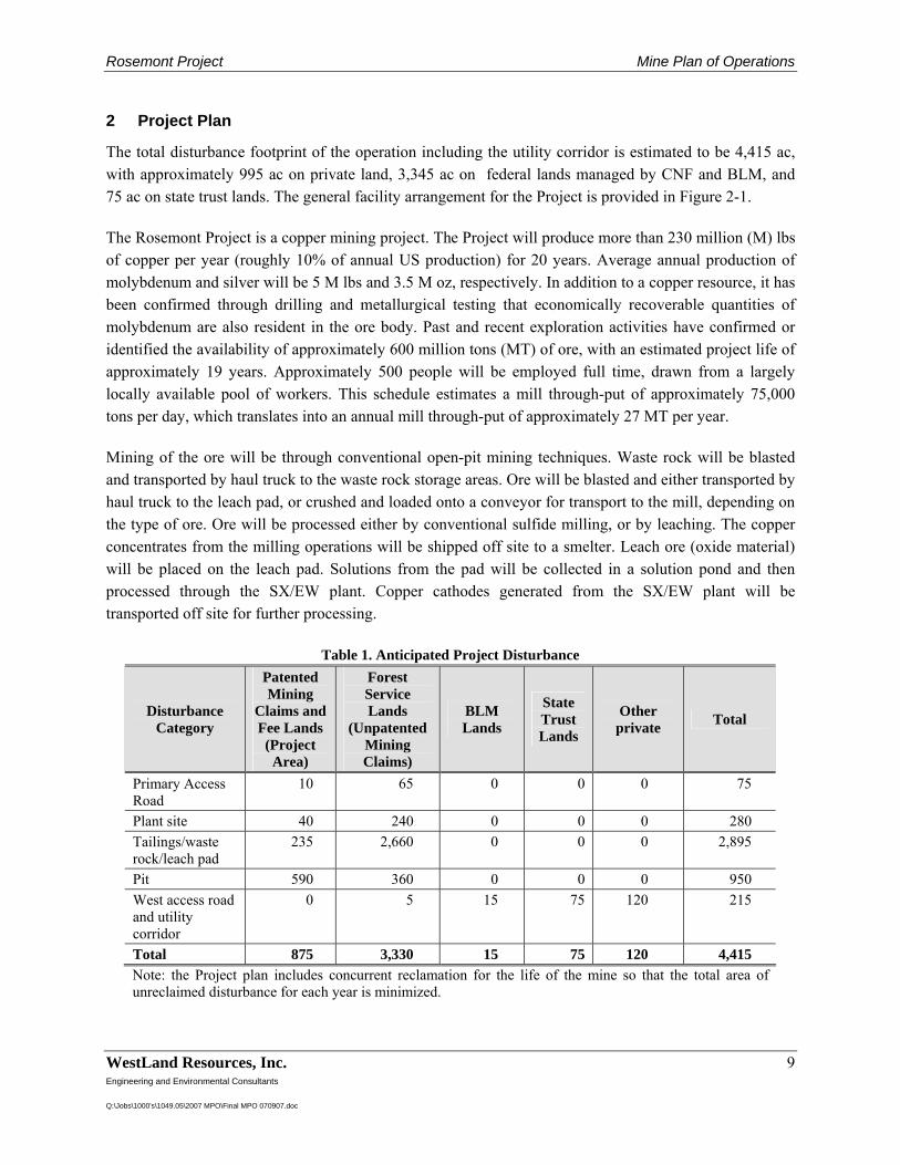
The total disturbance footprint of the operation including the utility corridor is estimated to be 4,415 ac, with approximately 995 ac on private land, 3,345 ac on federal lands managed by CNF and BLM, and 75 ac on state trust lands. The general facility arrangement for the Project is provided in Figure 2-1. The Rosemont Project is a copper mining project. The Project will produce more than 230 million (M) lbs of copper per year (roughly 10% of annual US production) for 20 years. Average annual production of molybdenum and silver will be 5 M lbs and 3.5 M oz, respectively. In addition to a copper resource, it has been confirmed through drilling and metallurgical testing that economically recoverable quantities of molybdenum are also resident in the ore body. Past and recent exploration activities have confirmed or identified the availability of approximately 600 million tons (MT) of ore, with an estimated project life of approximately 19 years. Approximately 500 people will be employed full time, drawn from a largely locally available pool of workers. This schedule estimates a mill through-put of approximately 75,000 tons per day, which translates into an annual mill through-put of approximately 27 MT per year. Mining of the ore will be through conventional open-pit mining techniques. Waste rock will be blasted and transported by haul truck to the waste rock storage areas. Ore will be blasted and either transported by haul truck to the leach pad, or crushed and loaded onto a conveyor for transport to the mill, depending on the type of ore. Ore will be processed either by conventional sulfide milling, or by leaching. The copper concentrates from the milling operations will be shipped off site to a smelter. Leach ore (oxide material) will be placed on the leach pad. Solutions from the pad will be collected in a solution pond and then processed through the SX/EW plant. Copper cathodes generated from the SX/EW plant will be transported off site for further processing.
Table 1. Anticipated Project Disturbance
Disturbance Category
Patented Mining
Claims and Fee Lands (Project Area)
Forest Service Lands
(Unpatented Mining Claims)
BLM Lands
State Trust Lands
Other private Total
Primary Access Road
10 65 0 0 0 75
Plant site 40 240 0 0 0 280 Tailings/waste rock/leach pad
235 2,660 0 0 0 2,895
Pit 590 360 0 0 0 950 West access road and utility corridor
0 5 15 75 120 215
Total 875 3,330 15 75 120 4,415 Note: the Project plan includes concurrent reclamation for the life of the mine so that the total area of unreclaimed disturbance for each year is minimized.
Rosemont Project Mine Plan of Operations
WestLand Resources, Inc. 10 Engineering and Environmental Consultants Q:\Jobs\1000's\1049.05\2007 MPO\Final MPO 070907.doc
2.1 Mine Plan
2.1.1 Open Pit Plans
The ultimate extent of the pit is based on long-range price forecasts for copper, molybdenum and silver, as well as engineering estimates of operating costs, concentrator recoveries, anticipated smelting charges, and payment terms. The design of the open pit and internal mining phases incorporates geotechnical recommendations for safe slope angles, internal ramp development for access to all working areas, and pit wall smoothing to enhance stability and operator safety. Pit slope angles between ramps will vary according to rock strength, lithology and structural controls, but are expected to range between 28° and 48° between ramps. Where possible, catch benches will be spaced on 100-ft vertical intervals to maximize the effective widths for containing scree. Floating cone analyses of the economic pit limits were conducted using copper prices of US$1.20/lb to US$1.50/lb (below three-year trailing averages), with corresponding molybdenum prices of US$10.00/lb to US$15.00/lb. The basis for mine planning was the US$1.50/lb copper pit shell, which contains an estimated 600 MT of ore and 1,288 MT of waste rock. Oxide (heap leach ore) is presently estimated at 50 MT of mineralized material, which is contained within the above ore figures. At the rim, the ultimate open pit will be about 6,500 ft across north to south, 6,000 ft across east to west, and will be about 1,800 to 2,900 ft deep. The pit bottom elevation is projected at 3,150 ft above msl. The pit area totals about 700 ac, and an additional 300 ac will be disturbed for access/haul roads, ore stockpiles, the primary crusher and overland conveyor, power lines, water pipelines, truck shop, and storage of fuel and lubricants. Seven conceptual mining phases, or pushbacks, have been developed for a feasibility study of the Rosemont Project and used to generate a mine production schedule. The first phase, or starter pit, will be located toward the southwest corner of the ultimate pit, leaving about a 300-ft-wide subsequent pushback in Phase 5 that will extend to the final limits along the west side. Phase 2 expands the starter pit to the east and north. Phase 3 further extends the pit to the east, and Phase 4 expands the open pit to the north and east. Phase 5 will enlarge the pit on the west and southwest sides to their ultimate limits. Phases 6 and 7 progressively expand the pit to the east and southeast, following the orebody down its easterly slope. Each phase will develop about two to four years of sulfide ore reserves. The current ultimate pit plan is presented in Figure 2-1. Pit contours are shown at mid-bench elevations on vertical intervals of 50 ft. 2.1.2 Mine Haul Roads
Mine haul roads will be constructed around the north, east and south edges of the planned ultimate pit limits (Figure 2-1). Temporary haul roads will be constructed internal to the ultimate pit limits as
Rosemont Project Mine Plan of Operations
WestLand Resources, Inc. 11 Engineering and Environmental Consultants Q:\Jobs\1000's\1049.05\2007 MPO\Final MPO 070907.doc
necessary to provide access to all working faces in the open pit and connecting with the primary crusher, oxide leach pad and waste rock storage areas located to the southeast, east and northeast of the pit. Mine haul roads will be constructed using material excavated within the open pit, typically consisting of limestone, skarn, arkose, andesite and quartz monzonite porphyry rock types. Road surface material may be crushed and screened as needed to produce a smooth running surface. Pit haul roads will generally be 125-ft wide, inclusive of safety berms and ditches, and will support the traffic of 260-T off-highway mine haulage trucks. The gradient for the mine haul roads will be 10%, although short intervals may be constructed as steep as 12%. The minimum inside lane radius for switchbacks within the pit will be 40 ft. Roads will be slightly crowned to promote drainage of surface runoff to side ditches or berms. Safety berms will be constructed to a minimum height of about 6 to 8 ft, the height at the center of the largest truck wheel. Haul truck speeds will not exceed 35 mph and will usually be less than 25 mph on ramp gradients of 10% or more. Haul truck traffic will follow the convention of left-hand drive in the pit, leach pad, and waste rock areas. Dust will be suppressed by wetting the road surfaces using a fleet of appropriately-sized water trucks with up to 30,000-gallon tank capacities. An access road will also be constructed between the open pit and the truck shop located near the plant site. This road will have the same design parameters and speed limits as the mine haul roads. 2.1.3 Pit Production Schedule
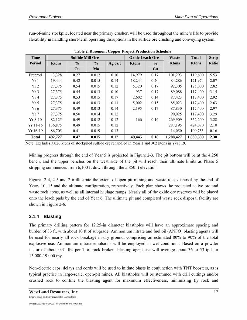
Sulfide milling is scheduled for 24 hours per day, 7 days per week, 365 days per year at an ore processing rate of 75,000 tpd, or 27 MT per annum. The open pit mine will operate using the same schedule. The Project will use four rotating crews, each working 12-hour shifts, to provide continuous operator coverage. The Project’s production schedule is presented in Table 2. Preproduction stripping will require 18 months to prepare for full-scale mine operations, training work crews, constructing access and haul roads, and clearing and grubbing the pit and waste rock storage areas that will be disturbed during the initial years of operation. Peak material handling rates will occur in Years 1 to 2, averaging about 342,000 tpd of total material before falling off to nearly 322,000 tpd for Years 3 to 12. Sulfide ore will be directed to the primary crusher and concentrator, while oxide ore will be placed on a leach pad. Treatment of pit-run waste rock and dewatered mill tailings is discussed in Section 2.3. Figure 2-2 shows the extent of mining and the waste rock disposal areas at the end of the preproduction period. The pit bottom will reach the 5,050 elevation in Phase 1, and waste stripping in Phase 2 will advance to the 5,250 bench. A 3.3-MT sulfide ore stockpile will be constructed near the primary crusher, mostly within the ultimate pit limits, to facilitate subsequent recovery in Year 1 of mill operations. A
Rosemont Project Mine Plan of Operations
WestLand Resources, Inc. 12 Engineering and Environmental Consultants Q:\Jobs\1000's\1049.05\2007 MPO\Final MPO 070907.doc
run-of-mine stockpile, located near the primary crusher, will be used throughout the mine’s life to provide flexibility in handling short-term operating disruptions in the sulfide ore crushing and conveying system.
Table 2. Rosemont Copper Project Production Schedule Sulfide Mill Ore Oxide Leach Ore Time
Period Ktons % Cu
% Mo
Ag oz/t Ktons % Cu
Waste Ktons
Total Ktons
Strip Ratio
Preprod Yr 1 Yr 2 Yr 3 Yr 4 Yr 5 Yr 6 Yr 7
Yr 8-10 Yr 11-15 Yr 16-19
3,328 19,444 27,375 27,375 27,375 27,375 27,375 27,375 82,125
136,875 86,705
0.27 0.42 0.54 0.45 0.53 0.45 0.49 0.50 0.49 0.49 0.41
0.012 0.015 0.015 0.013 0.015 0.013 0.013 0.014 0.012 0.015 0.019
0.10 0.14 0.12 0.10 0.17 0.11 0.14 0.12 0.12 0.12 0.13
14,979 18,244 5,320
937 2,602 5,002 2,195
166
0.17 0.20 0.17 0.17 0.14 0.15 0.17
0.16
101,293 84,286 92,305 89,088 87,423 85,023 87,830 90,025
269,909 287,195
14,050
119,600 121,974 125,000 117,400 117,400 117,400 117,400 117,400 352,200 424,070 100,755
5.53 2.07 2.82 3.15 2.92 2.63 2.97 3.29 3.28 2.10 0.16
Total 492,727 0.47 0.015 0.12 49,445 0.18 1,288,427 1,830,599 2.38 Note: Excludes 3,026 ktons of stockpiled sulfide ore rehandled in Year 1 and 302 ktons in Year 19.
Mining progress through the end of Year 5 is projected in Figure 2-3. The pit bottom will be at the 4,250 bench, and the upper benches on the west side of the pit will reach their ultimate limits as Phase 5 stripping commences from 6,100 ft down through the 5,850 ft elevation. Figures 2-4, 2-5 and 2-6 illustrate the extent of open pit mining and waste rock disposal by the end of Years 10, 15 and the ultimate configuration, respectively. Each plan shows the projected active ore and waste rock areas, as well as all internal haulage ramps. Nearly all of the oxide ore reserves will be placed onto the leach pads by the end of Year 6. The ultimate pit and completed waste rock disposal facility are shown in Figure 2-6. 2.1.4 Blasting
The primary drilling pattern for 12.25-in diameter blastholes will have an approximate spacing and burden of 33 ft, with about 10 ft of subgrade. Ammonium nitrate and fuel oil (ANFO) blasting agents will be used for nearly all rock breakage in dry ground, comprising an estimated 80% to 90% of the total explosive use. Ammonium nitrate emulsions will be employed in wet conditions. Based on a powder factor of about 0.31 lbs per T of rock broken, blasting agent use will average about 36 to 53 tpd, or 13,000-19,000 tpy. Non-electric caps, delays and cords will be used to initiate blasts in conjunction with TNT boosters, as is typical practice in large-scale, open-pit mines. All blastholes will be stemmed with drill cuttings and/or crushed rock to confine the blasting agent for maximum effectiveness, minimizing fly rock and
Rosemont Project Mine Plan of Operations
WestLand Resources, Inc. 13 Engineering and Environmental Consultants Q:\Jobs\1000's\1049.05\2007 MPO\Final MPO 070907.doc
over-pressure, and therefore surface noise. Best blasting practices and timing procedures will be employed to minimize off-site ground vibrations, as measured by peak particle velocity, to prevent damage to structures. Blasting operations will be conducted daily and will be limited to daylight hours, typically between 9:00 a.m. and 4:00 p.m. local time, under the supervision of certified blasters who are either employed directly by the company or by licensed contractors. Access to blasting areas will be restricted to authorized personnel only, who will follow strict safety and communication procedures. Blasting caps and boosters will be stored in secure magazines located south of the open pit and west of the waste rock storage area. The magazines will be constructed to meet all applicable fire code, Bureau of Alcohol Tobacco and Firearms security standards, and industry safety standards, and will be accessible only to authorized personnel. Bulk ammonium nitrate will be stored in silos located northwest of the truck shop area and south of the mill site (Figure 2-1). An on-site emulsion plant may be located nearby, depending on the extent of wet blasting conditions and emulsion usage. Blasting agents will be transported to the blast site in ANFO emulsion product delivery trucks or prill trucks designed to carry ANFO as each hole is loaded. Caps, delays, cords and boosters will be transported from the magazines to the blast site in a separate vehicle. 2.1.5 Ore Transport
Sulfide ore will be transported via large (260-T) off-highway haul trucks from the open pit to the primary crusher, which will be located near the east pit rim. After crushing, the sulfide ore will travel by overland conveyor to a covered crushed ore stockpile. The material will then pass through feeders and onto another conveyor that will discharge into the semi-autogenous grinding (SAG) mill at a daily rate of 75,000 tpd. A run-of-mine (ROM) coarse ore stockpile will be located near the primary crusher to temporarily hold sulfide ore mined before mill startup. The stockpile will also provide equipment utilization flexibility and short-term ore storage in case of interruptions in crusher operation. The ROM stockpile will hold 100,000 to 200,000 T of sulfide ore, but will reach a projected maximum size of about 3.3 MT at the end of preproduction stripping. Oxide ore will be transported from the open pit to the leach pad by haul trucks. The oxide ore will not be crushed, but will be dumped in 30-ft-high lifts atop the lined pad for subsequent leaching. Crawler dozers will be used to spread the oxide ore and cross rip the material to a depth of 5 to 6 ft to promote the infiltration of barren leach solution. Oxide ore mining and placement on the leach pad will be concentrated in the early years of operation, peaking at about 51,000 tpd in Year 1. Nearly all of the oxide ore will be placed onto the leach pad by the end of Year 6. Leach ore placement rates will be dictated by how much oxide ore is encountered when supplying 75,000 tpd of sulfide ore to the mill. These placement rates will vary considerably over the long and short term. Initially, oxide ore will be delivered to the leach pad at rates in excess of what can be leached and
Rosemont Project Mine Plan of Operations
WestLand Resources, Inc. 14 Engineering and Environmental Consultants Q:\Jobs\1000's\1049.05\2007 MPO\Final MPO 070907.doc
processed by the solvent extraction (SX) plant. Consequently, not all of the material will be placed under leach at once; different sections will be leached according to copper recovery, solution balances, and other metallurgical considerations. Figure 2-1 shows the general site arrangement, including the locations of the ROM ore stockpile, primary crusher and overland conveyor, crushed sulfide ore storage, and oxide leach pad areas. 2.1.6 Waste Rock
The waste rock storage areas will be located to the southeast, east and northeast of the proposed open pit, as shown in Figure 2-1. The waste rock storage areas will receive pit-run waste rock consisting largely of limestone and skarn rock types, with some andesite, quartz monzonite porphyry and arkose. The presence of substantial quantities of limestone and skarn will provide a large buffering capacity within the waste-rock storage areas to minimize the generation of acid rock drainage (ARD). Waste rock production from the pit will range from about 195,000 tpd to a maximum of nearly 267,000 tpd. Portions of the waste rock storage areas will also receive dry (filtered) tailings from the sulfide ore processing plant at a nominal rate of 73,600 dry tpd. This material will be stacked behind large containment berms constructed from pit-run waste rock. The construction of the dry tailings and pit waste rock storage facilities is described in more detail in Section 2.3. 2.1.7 Mine Equipment
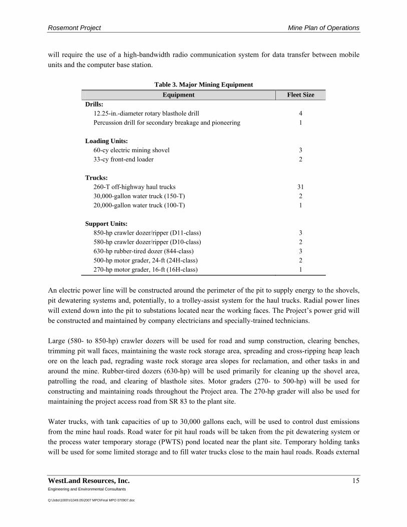
The major pieces of mining equipment required to fulfill the production schedule are summarized in Table 3. The final equipment selection and fleet sizes may vary slightly with vendor selection and future mine optimization studies. Production blasthole drilling will be performed by diesel- and electrically powered rotary rigs capable of 120,000 to 130,000 lbs of bit loading (pulldown) pressure using 12.25-in -diameter tri-cone bits. A diesel-powered percussion drill (3.5- to 4-in. diameter holes) will be used for road and bench pioneering work and secondary rock breakage. Electrically-powered mining shovels with 60 cy dippers will perform the bulk of the ore and waste rock loading. Two 33-cy front-end loaders will augment the shovel fleet and be used for safety berm maintenance, bench pioneering, road construction, bench toe cleanup, and constructing pit-bottom sumps. Off-highway trucks will be used for the production haulage of all ore and waste rock. These will be diesel-powered units with either mechanical or electrical drive systems. The final truck selection will be based on manufacturers’ supply capabilities, tire availability, and economic considerations. Rosemont is investigating the use of an electric trolley-assist system to reduce diesel fuel consumption. A computer-based truck dispatch system will be employed to direct haul trucks to available loading units, maximize unit truck productivities, and maintain production and performance records of the mine operations. This
Rosemont Project Mine Plan of Operations
WestLand Resources, Inc. 15 Engineering and Environmental Consultants Q:\Jobs\1000's\1049.05\2007 MPO\Final MPO 070907.doc
will require the use of a high-bandwidth radio communication system for data transfer between mobile units and the computer base station.
Table 3. Major Mining Equipment Equipment Fleet Size
Drills: 12.25-in.-diameter rotary blasthole drill Percussion drill for secondary breakage and pioneering Loading Units: 60-cy electric mining shovel 33-cy front-end loader Trucks: 260-T off-highway haul trucks 30,000-gallon water truck (150-T) 20,000-gallon water truck (100-T) Support Units: 850-hp crawler dozer/ripper (D11-class) 580-hp crawler dozer/ripper (D10-class) 630-hp rubber-tired dozer (844-class) 500-hp motor grader, 24-ft (24H-class) 270-hp motor grader, 16-ft (16H-class)
4 1
3 2
31 2 1
3 2 3 2 1
An electric power line will be constructed around the perimeter of the pit to supply energy to the shovels, pit dewatering systems and, potentially, to a trolley-assist system for the haul trucks. Radial power lines will extend down into the pit to substations located near the working faces. The Project’s power grid will be constructed and maintained by company electricians and specially-trained technicians. Large (580- to 850-hp) crawler dozers will be used for road and sump construction, clearing benches, trimming pit wall faces, maintaining the waste rock storage area, spreading and cross-ripping heap leach ore on the leach pad, regrading waste rock storage area slopes for reclamation, and other tasks in and around the mine. Rubber-tired dozers (630-hp) will be used primarily for cleaning up the shovel area, patrolling the road, and clearing of blasthole sites. Motor graders (270- to 500-hp) will be used for constructing and maintaining roads throughout the Project area. The 270-hp grader will also be used for maintaining the project access road from SR 83 to the plant site. Water trucks, with tank capacities of up to 30,000 gallons each, will be used to control dust emissions from the mine haul roads. Road water for pit haul roads will be taken from the pit dewatering system or the process water temporary storage (PWTS) pond located near the plant site. Temporary holding tanks will be used for some limited storage and to fill water trucks close to the main haul roads. Roads external
Rosemont Project Mine Plan of Operations
WestLand Resources, Inc. 16 Engineering and Environmental Consultants Q:\Jobs\1000's\1049.05\2007 MPO\Final MPO 070907.doc
to the pit will be watered using fresh water. Separate water stands and holding tanks will be maintained for this purpose. In addition to the major mining equipment described above, the Rosemont mine operations and maintenance crews will require other support equipment, including, but not limited to, explosive/blasting agent delivery trucks, an 8-cy front-end loader, 25-T haul trucks (for stemming deliveries and spreading aggregate), backhoe/loaders, a portable aggregate crushing and screening plant (brought in periodically by a contractor to produce stemming and road surfacing material), an all-terrain crane, fuel/lube trucks, mechanic field service trucks, a 200-T transporter/trailer, a tire handling truck, integrated tool carriers, forklifts, light plants, pickup trucks and crew vans. 2.1.8 Mine Staffing
The number of mine operations employees (excludes plant, administration, etc.) will vary with the waste rock stripping rates and the increasing depth of the pit over time, both of which affect haulage profiles and the number of truck drivers. Generally, the number of pit operations employees per shift will range from 148 to 181 people. With four rotating crews working 12-hour shifts, mining crews will average about 37 to 45 people for each shift. Operating personnel will consist of drillers, blasters, shovel and loader operators, truck drivers, dozer and motor grader operators, and a pool of laborers and trainees. Mine maintenance personnel required to support the Project’s operations will be about half the size of the operating crews. The Project’s maintenance crews will consist of heavy equipment and diesel mechanics, welders, electricians, instrument technicians, lubrication and tire service personnel, laborers, and trainees. Precision machining and component rebuilds will be generally performed off site by qualified vendors. Total mine maintenance personnel will range between 57 and 99 people, and will be distributed over four rotating crews working 12-hour shifts. Mine supervision, technical and support personnel will consist of about 45 people during most of the project’s life. These will include mine and maintenance superintendents, supervisors, maintenance planners, mining engineers, environmental and safety professionals, geologists, surveyors, engineering/ ore control technicians, and administrative support personnel. The mine operations total personnel requirements are projected at 250 to 325 people. The vast majority of the skilled mining personnel needed for the Rosemont Project are available in the greater Tucson area.
Rosemont Project Mine Plan of Operations
WestLand Resources, Inc. 17 Engineering and Environmental Consultants Q:\Jobs\1000's\1049.05\2007 MPO\Final MPO 070907.doc
2.2 Ore Processing
Ore will be processed using both milling and heap leaching technology. Copper, silver, and molybdenum will be recovered by grinding and froth flotation, with the principal recovered minerals being the copper sulfide minerals (bornite, chalcocite, and chalcopyrite) and the molybdenum sulfide mineral (also referred to as “moly”). Copper sulfide mineral concentrate (the end result of the milling process) produced at the mill facility will be loaded into highway haul trucks and transported off site to a copper concentrate smelter and metal refinery. Molybdenum concentrate produced at the mill site will be bagged and/or drummed and loaded onto trucks for shipment to market. The design basis for the sulfide ore processing facility is 75,000 dry tpd (dt/d) or 27,375,000 dry tons per year (dt/y). Metallic copper will be recovered by heap leaching, solvent extraction, and electrowinning. The principal mineral to be processed is copper oxide, or chrysocolla. Metallic copper will be produced from the copper oxide ore in the form of high purity, copper cathode plates. The copper cathode plates will be loaded onto trucks for shipment to market. The design basis for oxide ore processing is 9,000 dt/d or 3,285,000 dt/y. 2.2.1 Process Operations Overview
A summary of the process operations required to recover copper and molybdenum from the sulfide ore and metallic copper from the oxide ore is provided in the discussion below and in Figure 2-7. Sulfide Ore
• The rock size of the ore will be reduced to approximately 6-in in diameter with a gyratory crusher.
• The rock size will be reduced further, to less than 100-mesh, or about as fine as sand, by wet grinding in a mill grinding circuit using a semi-autogenous grinding (SAG) mill and ball mills.
• Using mineral flotation technology, the copper and molybdenum will be extracted from the finely ground ore and water slurry produced in the grinding circuit. The copper and molybdenum will be concentrated first into a copper/moly concentrate in a mineral flotation circuit. The molybdenum will then be separated from the copper minerals in a molybdenum flotation circuit.
• Once the moly is separated from the copper, the resultant copper concentrate will be thickened, filtered, and loaded into trucks for shipment. The molybdenum concentrate will be filtered, dried, and packaged into containers for shipment.
• Flotation circuit tailings, or reject mineral and waste material from the flotation circuit, will be thickened, filtered, transported by a conveyor system, and dry stacked behind an engineered starter buttress in the north or south dry stack tailings areas (Section 2.3).
• Water from tailings and concentrate dewatering operations will be recycled for reuse in the process.
Rosemont Project Mine Plan of Operations
WestLand Resources, Inc. 18 Engineering and Environmental Consultants Q:\Jobs\1000's\1049.05\2007 MPO\Final MPO 070907.doc
Oxide Ore
• Oxide ore will be delivered from the mine and placed onto a leveled heap on a lined area to be processed by heap leaching technology.
• A weak acidic solution, or raffinate, will be distributed on the surface of the piled ore using low-mist emitters. The solution will drain through the ore pile and dissolve the copper in the ore. The solution, now called pregnant leach solution, or pregnant leach solution (PLS), will be collected by a drainage network above the liner and directed to solution collection ponds (Figure 2-1).
• The PLS will be processed to recover copper using solvent extraction and SX/EW technology. Copper plates will be the final product of the SX/EW circuit.
2.2.2 Sulfide Ore Processing
2.2.2.1 Crushing
Sulfide ore will be trucked from the mine and dumped directly into the crusher dump pocket that feeds a primary gyratory crusher. The ore will fall through the crusher and be collected in a discharge bin. Primary crushed ore will be withdrawn from the bin by an apron type feeder. The apron feeder will discharge to a conveyor belt that will in turn feed a tripper stacking conveyor that discharges to an ore stockpile. Dust will be controlled in the crushing area with a wet scrubber dust collection system. 2.2.2.2 Coarse Ore Stockpile
Primary crushed ore will be stockpiled on the ground in a covered ore stockpile. A reclaim tunnel will be installed beneath the stockpile. Ore for the grinding circuit will be withdrawn from the coarse ore reclaim stockpile by apron feeders installed in the reclaim tunnel. The feeders will discharge to two conveyor belts installed in series which will in turn discharge to the SAG grinding mill. Dust in the coarse ore stockpile reclaim area will be controlled with a wet scrubber dust collection system similar to that in the crushing circuit. 2.2.2.3 Grinding
As mentioned above, ore will be ground in water to the final product size in a SAG mill primary grinding circuit and a ball mill secondary grinding circuit. The primary grinding SAG mill will operate in closed circuit with a trommel screen and a pebble crusher. Trommel undersize will be the final product from the SAG mill grinding circuit. Trommel oversize (hard
Rosemont Project Mine Plan of Operations
WestLand Resources, Inc. 19 Engineering and Environmental Consultants Q:\Jobs\1000's\1049.05\2007 MPO\Final MPO 070907.doc
rock pebbles) will be transported by belt conveyors to the pebble crusher where it will be processed and returned by belt conveyors to the SAG mill. Secondary grinding will be performed in two ball mills operated in parallel. Each ball mill will operate in a closed circuit with hydrocyclone classifiers. Ball mill discharge will be combined with trommel screen undersize and will be pumped to the hydrocyclones. Hydrocyclone underflow will be pumped to the ball mills. Hydrocyclone overflow, the final grinding circuit product, will flow by gravity to the flotation circuit. 2.2.2.4 Flotation Plant
2.2.2.4.1 Bulk (Copper-Moly) Flotation
Ore and water slurry will be processed in the bulk copper-moly flotation circuit. The circuit will consist of two rows of rougher flotation cells, two concentrate regrind circuits, four copper cleaner column flotation cells, and one row of copper cleaner scavenger flotation cells. The final product of the bulk copper-moly flotation circuit will be a mineral and water slurry containing copper and molybdenum minerals. 2.2.2.4.2 Molybdenum Flotation
Copper-moly concentrate will flow to a slurry thickener. Thickener overflow (water) will be pumped to the reclaimed water system. Thickener underflow (high density mineral slurry) will be pumped to the molybdenum flotation circuit. The molybdenum flotation circuit will consist of one row of rougher molybdenum separation, flotation cells, one row of molybdenum rougher concentrate cleaner flotation cells, a concentrate regrind circuit, one molybdenum second cleaner column flotation cell, and one molybdenum third cleaner column flotation cell. Tailing slurry from the molybdenum rougher cells and molybdenum first cleaner flotation cells will be final copper mineral concentrate and will flow to the copper concentrate dewatering circuit. Flotation concentrate from the molybdenum third cleaner cell will be final molybdenum mineral concentrate and will flow by gravity to the molybdenum concentrate dewatering circuit. 2.2.2.5 Concentrate Dewatering
2.2.2.5.1 Copper Concentrate Dewatering
Copper concentrate slurry will be dewatered and thickened in a copper concentrate thickener. Thickener overflow (water) will be pumped to the reclaim water system. Thickener underflow (thickened mineral slurry) will be pumped to copper concentrate filters. Filter cake will discharge to a conveyor belt and will discharge to a covered concentrate stockpile.
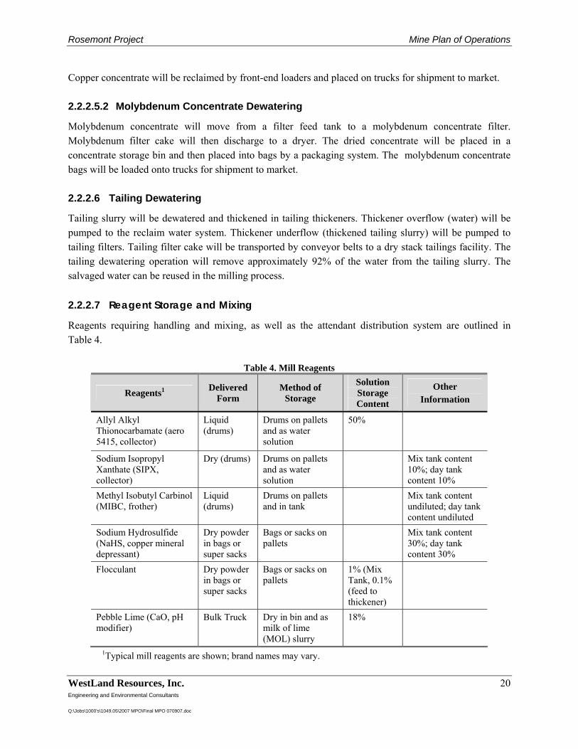
Rosemont Project Mine Plan of Operations
WestLand Resources, Inc. 20 Engineering and Environmental Consultants Q:\Jobs\1000's\1049.05\2007 MPO\Final MPO 070907.doc
Copper concentrate will be reclaimed by front-end loaders and placed on trucks for shipment to market. 2.2.2.5.2 Molybdenum Concentrate Dewatering
Molybdenum concentrate will move from a filter feed tank to a molybdenum concentrate filter. Molybdenum filter cake will then discharge to a dryer. The dried concentrate will be placed in a concentrate storage bin and then placed into bags by a packaging system. The molybdenum concentrate bags will be loaded onto trucks for shipment to market. 2.2.2.6 Tailing Dewatering
Tailing slurry will be dewatered and thickened in tailing thickeners. Thickener overflow (water) will be pumped to the reclaim water system. Thickener underflow (thickened tailing slurry) will be pumped to tailing filters. Tailing filter cake will be transported by conveyor belts to a dry stack tailings facility. The tailing dewatering operation will remove approximately 92% of the water from the tailing slurry. The salvaged water can be reused in the milling process. 2.2.2.7 Reagent Storage and Mixing
Reagents requiring handling and mixing, as well as the attendant distribution system are outlined in Table 4.
Table 4. Mill Reagents
Reagents1 Delivered Form
Method of Storage
Solution Storage Content
Other Information
Allyl Alkyl Thionocarbamate (aero 5415, collector)
Liquid (drums)
Drums on pallets and as water solution
50%
Sodium Isopropyl Xanthate (SIPX, collector)
Dry (drums) Drums on pallets and as water solution
Mix tank content 10%; day tank content 10%
Methyl Isobutyl Carbinol (MIBC, frother)
Liquid (drums)
Drums on pallets and in tank
Mix tank content undiluted; day tank content undiluted
Sodium Hydrosulfide (NaHS, copper mineral depressant)
Dry powder in bags or super sacks
Bags or sacks on pallets
Mix tank content 30%; day tank content 30%
Flocculant Dry powder in bags or super sacks
Bags or sacks on pallets
1% (Mix Tank, 0.1% (feed to thickener)
Pebble Lime (CaO, pH modifier)
Bulk Truck Dry in bin and as milk of lime (MOL) slurry
18%
1Typical mill reagents are shown; brand names may vary.
Rosemont Project Mine Plan of Operations
WestLand Resources, Inc. 21 Engineering and Environmental Consultants Q:\Jobs\1000's\1049.05\2007 MPO\Final MPO 070907.doc
2.2.3 Oxide Processing
2.2.3.1 Heap Leach
Oxide ore will be trucked from the mine to the leach pad. Details of the heap leach design are provided in Tetra Tech (2007f). The ore will be stacked on the lined leach pad area and irrigated with an acidified leach solution (raffinate). Drip emitters will distribute the leach solution to the surface of the ore to minimize evaporation losses. Sprays may be used on side slopes or to increase evaporation if required to maintain the process water balance. The leach solution will percolate through the leach pile and dissolve soluble copper from the ore before being directed along the impermeable leach pad liner to the solution collection system above the pad liner. The copper-bearing leach solution, or PLS, will flow by gravity from the leach pad to a double-lined collection pond, or PLS pond. A stormwater pond will be installed to collect any excess water that may be generated during a large precipitation event. The PLS pond will be designed to overflow to the stormwater pond. Water that may accumulate in the stormwater pond will be periodically transferred by pumping to the raffinate solution pond. (Figure 2-1). 2.2.3.2 Solvent Extraction and Electrowinning (SX/EW)
Copper contained in the aqueous phase PLS will be extracted from the solution with reagents carried in an organic phase solution in the SX circuit. The resulting copper-depleted aqueous solution, or raffinate, will be transferred to a storage pond (raffinate pond) before being reused in the heap leaching process. Copper transferred to the organic solution will be removed with an acidic aqueous solution, or lean electrolyte, that will have traveled through the EW circuit. This transfer of copper enriches the electrolyte solution, or rich electrolyte. The rich electrolyte will be returned to the EW cells for copper plating onto stainless steel blanks. The copper plated stainless steel blanks will be harvested from the EW cells. The copper will be removed from the stainless steel with a cathode stripping machine. Copper plates will be weighed and bundled into 2 to 3 T packages for shipment by truck to market. 2.2.3.3 SX/EW Reagents
Reagents requiring handling and mixing, as well as the attendant distribution system are outlined in Table 5.
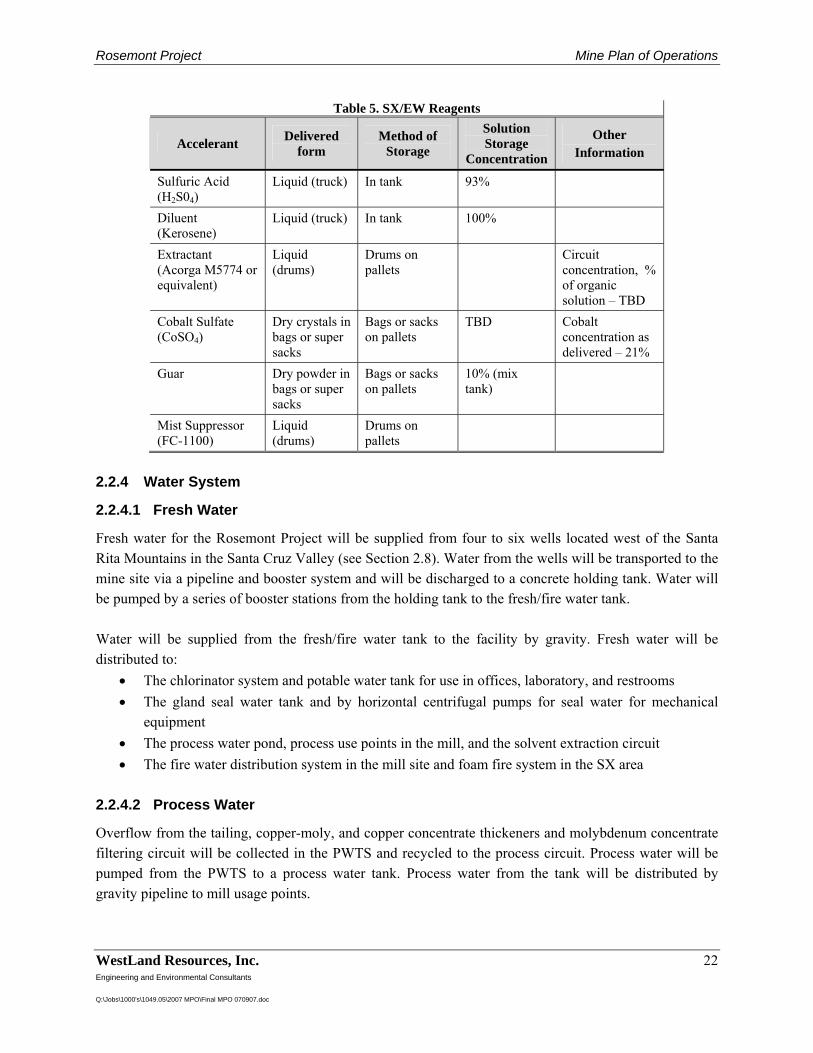
Rosemont Project Mine Plan of Operations
WestLand Resources, Inc. 22 Engineering and Environmental Consultants Q:\Jobs\1000's\1049.05\2007 MPO\Final MPO 070907.doc
Table 5. SX/EW Reagents
Accelerant Delivered form
Method of Storage
Solution Storage
Concentration
Other Information
Sulfuric Acid (H2S04)
Liquid (truck) In tank 93%
Diluent (Kerosene)
Liquid (truck) In tank 100%
Extractant (Acorga M5774 or equivalent)
Liquid (drums)
Drums on pallets
Circuit concentration, % of organic solution – TBD
Cobalt Sulfate (CoSO4)
Dry crystals in bags or super sacks
Bags or sacks on pallets
TBD Cobalt concentration as delivered – 21%
Guar Dry powder in bags or super sacks
Bags or sacks on pallets
10% (mix tank)
Mist Suppressor (FC-1100)
Liquid (drums)
Drums on pallets
2.2.4 Water System
2.2.4.1 Fresh Water
Fresh water for the Rosemont Project will be supplied from four to six wells located west of the Santa Rita Mountains in the Santa Cruz Valley (see Section 2.8). Water from the wells will be transported to the mine site via a pipeline and booster system and will be discharged to a concrete holding tank. Water will be pumped by a series of booster stations from the holding tank to the fresh/fire water tank. Water will be supplied from the fresh/fire water tank to the facility by gravity. Fresh water will be distributed to:
• The chlorinator system and potable water tank for use in offices, laboratory, and restrooms • The gland seal water tank and by horizontal centrifugal pumps for seal water for mechanical
equipment • The process water pond, process use points in the mill, and the solvent extraction circuit • The fire water distribution system in the mill site and foam fire system in the SX area
2.2.4.2 Process Water
Overflow from the tailing, copper-moly, and copper concentrate thickeners and molybdenum concentrate filtering circuit will be collected in the PWTS and recycled to the process circuit. Process water will be pumped from the PWTS to a process water tank. Process water from the tank will be distributed by gravity pipeline to mill usage points.
Rosemont Project Mine Plan of Operations
WestLand Resources, Inc. 23 Engineering and Environmental Consultants Q:\Jobs\1000's\1049.05\2007 MPO\Final MPO 070907.doc
2.3 Waste Rock and Mill Tailings Management
2.3.1 Tailings and Waste Rock Characterization
A geochemical testing program has been conducted to characterize the tailings and waste rock materials and to develop a preliminary approach for ARD classification of the waste rock. This geochemical testing program is detailed in Tetra Tech (2007a). The results of the testing program indicate that the majority of the waste rock sampled will be non-acid generating NAG), though ARD potential has been factored into the design. 2.3.2 Waste Rock Management Strategy
2.3.2.1 General
Waste rock will be managed in areas located to the southeast, east and northeast of the proposed open pit, as shown in Figure 2-1. The placement of waste rock on the south and east sides of the waste rock facility will be initiated with perimeter buttresses designed to minimize the visual effects of the project for travelers on SR 83 and for viewers in the surrounding area. The outside face of the buttresses will be revegetated and reclaimed as they are completed. Waste rock in the remaining portions of each phase will then be deposited west and/or north of (behind) these buttresses. Waste rock will also be placed in the dry-stack tailings storage areas to provide structural and erosional stability of the tailings pile. Waste rock may be used for general site grading. Additional discussion of the dry tailings management plan is provided in Section 2.3.3. Initial development of the waste rock storage area will begin with starter buttresses on the east and south sides. Construction of these buttresses will continue through approximately five years after plant startup and will require about 218 MT of waste rock from open pit operations. The final crest elevations of the perimeter buttresses will be about 5,400 ft, but will step down on the northeast side in a couple of segments (at elevations of 5,150 and 5,050 ft) to meet dry-tailings storage capacity requirements and operational considerations for the oxide heap leach facility. Concurrent with the starter buttress construction, waste rock will be deposited in lifts internal to the waste rock storage area in the upper Barrel Canyon drainage behind the buttresses. This concurrent development is necessary to minimize congestion and improve safety and equipment productivity in the buttress areas. The waste rock storage area south of the oxide heap leach facility will be filled in to the 5,400 ft elevation (to be level with the perimeter buttress crests) near the end of Year 9. Beginning in Year 10, after three years of leaching, rinsing and drain down of the oxide heap leach stockpile, waste rock will be deposited over the decommissioned oxide heap leach facility. By Year 15, the oxide leach area will be fully buried and new waste rock storage lifts will be constructed at crest elevations of 5,450 and 5,500 ft. The 5,500-ft lift will be short-lived, as waste rock will then be excavated from the upper portions of the waste rock storage area to supply buttressing and capping material for the dry-stack tailings area during Years 16 to 19. The total capacity of the waste rock storage area at the end of mining operations is estimated at 980 million T and the ultimate crest elevation will be about 5,475 ft.
Rosemont Project Mine Plan of Operations
WestLand Resources, Inc. 24 Engineering and Environmental Consultants Q:\Jobs\1000's\1049.05\2007 MPO\Final MPO 070907.doc
The lower Barrel Canyon area will be reserved for dry tailings storage; however, a significant volume of waste rock will be utilized as buttressing materials to construct the dry tailings stack over the life of the mine. The lower Barrel Canyon storage area will have an ultimate crest elevation of about 5,250 ft. All of the waste management areas will receive pit-run waste rock consisting largely of limestone and skarn rock types, with some andesite, quartz monzonite porphyry, and arkose. The presence of substantial quantities of limestone and skarn, along with low-sulfide content, will provide a large buffering capacity within the waste rock storage areas to minimize the generation of ARD. Waste rock production from the pit will range from 130,000 tpd to a maximum of nearly 270,000 tpd. Waste rock will be hauled to the dumping faces along the advancing edges of the waste storage facility. Haul trucks will back up to the dumping face, which is protected by a safety berm, and dump rock over the side. Loads may occasionally be dumped atop the current lift, particularly when another overriding lift or surface regrading is planned for the area. Dozers will be used to maintain safety berms along all waste rock storage facility crests, pushing excess material over the face and maintaining proper surface gradients for drainage. Previously undisturbed areas affected by advancing waste rock storage facilities will be cleared and grubbed prior to the deposition of pit-run or dry tailings material. Any growth media encountered will be stored for use in future reclamation activities or placed directly into active reclamation areas. As advancing waste rock faces approach the ultimate limits of the storage facility, setbacks will be used for each lift to approximate a 3:1 (horizontal to vertical) slope. By managing lift widths, the ultimate slope of the waste rock piles, from toe to crest, will be approximately 4H:1V. The final faces will be regraded by pushing down the crests and smoothing the overall slope to the 4H:1V gradient. Growth media will then be spread across the surface, seeded, fertilized and managed as necessary to promote revegetation of the waste rock storage area. Reclamation of these areas will be conducted as soon as the ultimate waste rock facility limits have been reached, which is anticipated to be concurrent with waste rock disposal operations in other parts of the storage facility. 2.3.2.2 Waste Rock Characterization and Control
Waste rock materials will be sorted during mining into acid generating (AG) and NAG categories so that each material can be placed in designated zones. ARD classification of the waste rock will be determined using pre-mining geochemical test results with verification by periodic sampling and assaying on representative blasthole cuttings in the mine. The assay will be performed by total sulfur testing at an on-site laboratory, with potential carbon content analysis to assist in refining waste rock classification. Some samples may have elevated total sulfur contents, but the concomitant presence of high carbonate contents would indicate the rock is likely to behave as NAG material under field conditions. Following laboratory testing, blasted waste materials will be flagged in the field for identification, and haul trucks will be directed to the appropriate location.
Rosemont Project Mine Plan of Operations
WestLand Resources, Inc. 25 Engineering and Environmental Consultants Q:\Jobs\1000's\1049.05\2007 MPO\Final MPO 070907.doc
AG waste rock will not be used for construction of the perimeter buttresses, tailings starter buttresses, drains, or required channel grading fills. It will be placed in the interior of the waste rock storage areas for burying and isolation. 2.3.2.3 Foundation Preparation and Stability
Portions of the waste rock areas may be required to be cleared and grubbed of organic materials. Suitable foundation materials will be stockpiled for later use in reclamation. The remaining alluvial and overburden soils and rocks following clearing and grubbing (and any foundation stripping) will be considered suitable foundation materials. The waste rock will be placed with a final inter-bench slope of 3H:1V. In addition, detailed stability analyses will be carried out during final design to ensure that the waste rock piles will be stable during and after placement. 2.3.2.4 Collection and Treatment of Waste Rock Drainage
The waste rock management facilities will be constructed in lifts that will generally not exceed 250 ft in height and will not extend beyond the divide that defines the eastern and southern edges of the Barrel Canyon drainage basin. The top surfaces will be constructed with upward gradients of about 0.5% to the southeast, east and northeast so that stormwater runoff is directed back toward the open pit. The stormwater will be collected along the western toes of the waste rock facilities and allowed to drain through the coarse rock along the bottom. Similarly, surface runoff from the eastern faces will be allowed to collect along the toes and drain through the base of the waste rock storage facilities. This water, along with surface water runoff from the active face of the waste rock storage area will ultimately be collected in a sediment pond located northeast of the tailings storage area. This pond will provide sediment control and water catchment for all of the disturbed areas within the Barrel Canyon drainage system. Water quality modeling is ongoing, but understanding of the current site suggests that runoff and/or seepage water from the waste rock storage areas will not exhibit elevated concentrations of metals and major ions. The results of the modeling are expected to suggest that drainage from the waste rock facility is suitable for direct discharge into ambient receiving water bodies. Runoff and seepage from the waste rock facility will be sampled and tested for water quality to verify modeling results. The sediment pond will serve as a final control point for water quality prior to discharge. Suspended sediments will settle out in the collection pond downstream of the waste rock facility, and the clarified water will be released.
Rosemont Project Mine Plan of Operations
WestLand Resources, Inc. 26 Engineering and Environmental Consultants Q:\Jobs\1000's\1049.05\2007 MPO\Final MPO 070907.doc
2.3.3 Tailings Dry-Stack Facility Design
2.3.3.1 General
The Rosemont dry-stack tailings facility will receive dry tailings from the sulfide ore processing plant at a nominal rate of 73,600 dry tpd. This material will be stacked behind large containment berms constructed from pit-run waste rock. Consequently, this waste rock storage area will be active from late preproduction throughout the life of the mine, presently estimated at 19 years. 2.3.3.2 Design Criteria
Design criteria and objectives for the dry stack tailings storage include:
• Provision of secure, long-term storage of 500 MT of dry tailings, which is sufficient for the ore to be mined and processed during approximately 19 years of project life at a projected rate of 75,000 tpd
• Location within the immediate area of the mine in an approximately 5-mi radius from the proposed mine pit
• Minimization of airborne release of tailings solids to the environment using dust suppression measures
• Minimization of water seepage from tailings into groundwater, in compliance with all applicable regulations including Arizona Aquifer Protect Permit (APP) requirements and associated BADCT standards
• Creation of a site-specific design that accounts for local factors including climate, geology, hydrogeology and seismicity
• Establishment of an effective and efficient reclamation program, with a focus on concurrent reclamation
2.3.3.3 Previous Studies
A siting study to identify the preferred tailings impoundment locations and disposal methods was conducted to evaluate alternatives. (Vector 2006). The evaluation was based on defined design and selection criteria as well as estimated development costs. This study provided a basis for the decision to advance the dry-stack tailings concept to feasibility-level design. The study considered both conventional (slurry) and dry-stack tailings disposal methods and included:
• Regional screening • Identification of sites • Analysis of fatal flaws
Rosemont Project Mine Plan of Operations
WestLand Resources, Inc. 27 Engineering and Environmental Consultants Q:\Jobs\1000's\1049.05\2007 MPO\Final MPO 070907.doc
• Investigation of remaining sites • Qualitative evaluation and ranking • Semi-quantitative evaluation and ranking • Cost analysis • Selection of alternatives for detailed investigation
The results of the study indicated the dry tailings option was the most favorable disposal method. Advantages of the dry stack tailings stack method over conventional tailings disposal are: it eliminates the need for an engineered embankment and seepage containment system; it maximizes water conservation and minimizes water makeup requirements; it results in a very compact site that limits disturbance to a single drainage; and, it allows opportunities for concurrent reclamation and dust control. 2.3.3.4 Dry-Stack Operations
A diversion ditch will be constructed upstream of the initial tailings placement area to convey stormwater to an adjacent drainage around the tailings facility (Figure 2-1). An initial buttress will be constructed with waste rock to accommodate approximately one year of tailings storage. The starter buttress is approximately 130 ft high with a top width of 450 ft. Concurrent tailings and waste rock placement will occur throughout the life of the tailings facility. Waste rock will be advanced ahead of the tailings level in successive lifts. The waste rock buttresses will have top widths of 150 ft to accommodate two-way haul traffic and outer slopes of 3H:1V with benches to achieve an overall slope of 3.5H:1V. This configuration will allow visual screening of the tailings placement activities from SR 83 and concurrent reclamation of the lower perimeter buttress slopes. Dry tailings will be delivered by conveyor from the filter plant down the drainage just below the planned diversion ditch. They will be placed with a radial stacker against the starter buttress. A dozer will be used to spread the dry tailings and provide sufficient compaction for the conveyor and stacker as necessary. When the primary conveyor is inactive due to relocation or maintenance, a second conveyor, constructed along the upper ridge area, will allow temporary disposal of tailings into the upper drainage area for placement with dozers. The tailings facility consists of two separate areas referred to as the north stack and the south stack. The north stack will operate in Years 1 through 14 and can accommodate approximately 375 MT of tailings. The south stack can store up to 170 MT of tailings during Years 15 through 19. An engineered rock drain will remain between the north and south stacks to convey surface water flow from the drainage above the process plant area to the existing Barrel drainage. Stormwater runon to the north stack will be limited by diverting the major drainage upstream of the stack area. Stormwater runoff sediments will be initially captured in a sediment pond located downstream of the tailings stack. A rock drain (“central drain”) will be constructed starting in Year 6 between the north and south stacks to convey surface water from the drainage above the process plant area. An attenuation pond
Rosemont Project Mine Plan of Operations
WestLand Resources, Inc. 28 Engineering and Environmental Consultants Q:\Jobs\1000's\1049.05\2007 MPO\Final MPO 070907.doc
immediately upgradient of the central drain is designed to temporarily store flows from the 100-year, 24-hour storm event will drain within 30 days. Flows will exit the downstream toe of the tailings facility and pass through a final compliance pond prior to release. The drain will extend to the top of the south tailings stack and allow surface water from the top of the stack to be conveyed through the drain following closure. Material to construct the drain will be from competent and inert waste rock sources. Stormwater runon to the south stack tailings operations will be controlled at the south limits of the tailings stack area by directing surface water flows from the adjacent waste rock pile away from the tailings area as much as practical. Direct runon from the immediately adjacent waste rock pile slopes will be controlled by temporary waste rock berms to direct surface water flows away from the tailings operation. Potential seepage migration to the south stack tailings operation will be controlled by impounding the water behind the planned haul road which forms the south terminus of the tailings facility and the north terminus of the waste rock pile. Prior to placement of tailings in the south stack area, the south face of the haul road fill will be sealed and covered with drain rock for protection. The drain rock will also promote drainage to the low point at the Barrel drainage where a sump will be constructed. The sump will be covered by the waste rock pile starting in Year 10, prior to tailings placement in the south stack, and the water level will be monitored over the life of the facility. The tailings surface will be sloped away from the starter buttresses constructed around the tailings stack to limit potential water impoundment against the buttress. Stormwater control for the tailings stack and the overall site is discussed in detail in Section 2.9 of this Plan. 2.3.4 ARD Monitoring
Monitoring will be implemented to confirm that the objectives of ARD prevention and control are being achieved. Monitoring will include the following:
• Water quality sampling and analysis downstream of the waste rock and tailings facilities throughout the life of the mine, closure period, and post-closure period until it is confirmed that there are no deleterious water quality issues. Note that water quality sampling will be completed for more than ARD parameters. See Section 3.1 of this Plan for further discussion.
• Groundwater sampling and analysis at strategically placed points-of-compliance monitoring wells downgradient of the facility. Sampling and analyses will be regulated under the requirements of the APP program in Arizona. See Section 3.1 of this Plan for further discussion.
• Quality control sampling of placed NAG materials to ensure that the waste material control system excludes any AG materials.
• Tracking of waste rock quantities by engineering personnel with respect to predicted and actual AG and NAG materials, including regular updates of relevant site material balances to ensure that the overall plan and strategy are maintained.
Rosemont Project Mine Plan of Operations
WestLand Resources, Inc. 29 Engineering and Environmental Consultants Q:\Jobs\1000's\1049.05\2007 MPO\Final MPO 070907.doc
• Installing wire piezometers at the base of the dry tailings stack to monitor the existence of phreatic head build-up during placement.
Rosemont Project Mine Plan of Operations
WestLand Resources, Inc. 30 Engineering and Environmental Consultants Q:\Jobs\1000's\1049.05\2007 MPO\Final MPO 070907.doc
2.4 Ancillary Facilities
The ancillary facilities necessary to support the Rosemont mine and ore processing operations include an administration building, change house, warehouse with lay down yards, analytical laboratory, light vehicle and process maintenance building, mine truck shop, mine truck wash and lube facility, powder magazines and ammonium nitrate storage, and a main guard shack with truck scale. Also included are fuel and lubricant storage and dispensing facilities for mine and process equipment. The ancillary facilities are shown in Figure 2-8 and are described below. Buildings will be painted to blend with the topographic back drop. 2.4.1 Administration Building
The administration building will be a single story pre-engineered steel building with corrugated metal roofing and siding located at the entrance to the plant, outside the fence line. Visitor and employee parking will also be provided outside the fence. This configuration will allow many of the site’s vendors and other visitors to access management and operating personnel without entering the process plant area. The administration building will be approximately 17,000 square feet (sf) and will house all the administrative and management personnel. 2.4.2 Change House
The employee change house will be a single story pre-engineered steel building with corrugated metal roofing and siding located at the entrance to the plant, inside the fence line. Employees will park in the designated parking area outside the fence and walk about 500 ft to the change house. It will be approximately 9,240 sf with a 660-sf extension for a boiler room, and will incorporate a health and safety office, employee training room, and ambulance garage. Separate changing rooms, with showers and bathrooms, will be provided for men and women. 2.4.3 Warehouse
The warehouse for mine and plant operations will be located next to the change house near the entrance of the plant. The warehouse will be a single story pre-engineered steel building with corrugated metal roofing and siding. It will be approximately 6,600 sf and includes an office, lunch room and restrooms. All materials and supplies will be received and stored at this warehouse. Satellite warehouse space will be provided in the mine truck shop and light vehicle repair shop for common and high use items. Delivery from the main warehouse to the satellite warehouse will be by Rosemont operations and maintenance personnel. This will minimize traffic inside the plant. 2.4.4 Analytical Laboratory
The analytical laboratory will be a single story pre-engineered building with corrugated roofing and siding located west of the warehouse near the entrance to the plant. The laboratory will be approximately 8,400 sf and will consist of a sample preparation area, wet laboratory, metallurgical laboratory, environmental laboratory, offices, lunch room and restrooms. A 15-ft overhang will be provided at the
Rosemont Project Mine Plan of Operations
WestLand Resources, Inc. 31 Engineering and Environmental Consultants Q:\Jobs\1000's\1049.05\2007 MPO\Final MPO 070907.doc
north end of the building to receive materials into the sample preparation area. The sample preparation area will be isolated from the analytical laboratory by a wall. It will contain sample crushers, pulverizers, sample splitters, and a dust collection system to capture and contain any dust generated from this operation. The analytical laboratory will contain the wet laboratory, reagent storage area, balance rooms, and analytical equipment. Also included is a facility to collect and manage waste chemicals in the laboratory. Disposal of the chemical or laboratory wastes will follow appropriate regulatory requirements dependent upon the waste generated. 2.4.5 Light Vehicle Repair Building and Fuel Storage
The light vehicle repair and process maintenance facility will be a single-story pre-engineered steel building located near the entrance to the plant about 200 ft south of the warehouse. The light vehicle repair building will be approximately 4,950 sf with a 20-ft eave height. Two bays of the building will have floor hoists for light vehicle repairs, and two open bays will be used for plant maintenance. A fifth bay, separating the light vehicle repair and plant maintenance facilities, will contain offices, a lunch room, tool room, and restrooms. A contained concrete pad at the north end of the building will contain storage tanks for used oil and antifreeze recovered from the maintenance operation. Bulk grease and lubricant storage and an air compressor will also be located in the contained area. Used antifreeze and used oil will be collected and returned to the supplier for recycling. A small vehicle fuel station will be located south of the light vehicle repair building along the east perimeter plant road. The light fuel station will contain a 10,000-gallon diesel storage tank and a 10,000-gallon gasoline storage tank. They will be located inside a concrete structure for secondary containment. Gasoline and diesel dispensing pumps will be provided on the west side of the storage tanks. A receiving station for fuel delivery trucks will be located on the east side of the storage tanks. Both the dispensing pumps and the receiving station will be on concrete pads, with any spills collected in a sump within the containment area. The fuel delivery trucks will travel on the east perimeter plant road only when delivering fuels and will not have to enter the process plant area. 2.4.6 Mine Truck Shop and Fuel Storage
The mine truck shop will be located about 1,600 ft south of the process facilities near the waste rock storage area and the pit exit. The operators will maintain left-hand traffic in the mine, the primary crusher dump pocket, on ore and waste haul roads, and to the mine truck shop. This configuration will provide a clear separation between the left-hand mine traffic and the right-hand traffic in the process plant. The mine truck shop will be approximately 20,000 sf. It will contain three bays to accommodate up to 360-T haul trucks and two bays for miscellaneous equipment such as graders, dozers and water trucks. The three mine truck bays will have an eave height of 67 ft, and the two bays for miscellaneous mine equipment will have an eave height of 36 ft. A 60-T service crane will be used to service the mine truck bays, and a 25-T service crane will be used to service the light equipment bays. The mine truck shop building will be an engineered steel building with corrugated steel roofing and siding because of the
Rosemont Project Mine Plan of Operations
WestLand Resources, Inc. 32 Engineering and Environmental Consultants Q:\Jobs\1000's\1049.05\2007 MPO\Final MPO 070907.doc
heavier loads from the service cranes. Embedded steel or rail will be installed in the two light equipment bays and one of the mine truck bays for servicing tracked equipment. The three mine truck bays will be drive-throughs; however, the two light equipment bays will not. Offices, restrooms, a mechanical/ electrical room, and a tool room will be positioned across one side of the two light equipment bays in a building extension of approximately 4,300 sf. A truck fuel storage and dispensing facility will be located adjacent and to the west of the truck shop. The facility will consist of two 100,000-gallon diesel storage tanks located within a concrete containment structure. Delivery trucks will unload on the west side of the storage tanks, and fuel dispensing stations for the mine trucks will be on the east side of the tanks. The west perimeter plant road will extend to the mine truck shop area to allow the fuel delivery trucks to access the tanks. Right hand traffic will extend to the west side of the fuel oil storage tanks and left hand mine traffic will remain on the east side. There will be no need for the fuel delivery trucks to enter left-hand traffic lanes to deliver fuel to the mine area. 2.4.7 Mine Truck Wash and Lube Facilities
A mine truck wash and lube facility will be located to the east of the mine truck shop. The facility will consist of an open concrete pad with four high pressure spray monitors to wash the undercarriage of the mine trucks. A steam generator and four hose stations will also be provided for steam cleaning where necessary. The concrete pad will drain to a concrete settling pit to recover solids and re-circulate the wash water back to a recycled-water tank. Water from the collection pit will overflow to an oil-skimming basin for oil recovery, then will be pumped to treatment equipment to remove residual oil and solids before returning to the recycled-water storage tank. The wash-water settling pit will contain an access ramp for a front-end loader to periodically reclaim the settled solids for disposal on the waste storage areas. An enclosed lube bay will be located opposite of the wash-water collection pit. The lube bay will be an engineered steel structure with corrugated metal roofing and siding, and will be open on the two ends for drive-through access. The eave height for this structure will be 55 ft to accommodate the haul trucks. The lube pad will contain embedded steel for track equipment and will also drain to the wash-water collection pit. A tank farm for the various lubrication oils and antifreeze, as well as used oil and used antifreeze, will be located to the west of the lube oil bay. These tanks will be in a concrete containment structure for spill control. Used oil and antifreeze will be collected and returned to the suppliers for recycling. 2.4.8 Powder Magazines and Ammonium Nitrate Silos
Separate magazines will be provided for blasting powder and detonator caps. The powder magazine will be a 30-ft by 30-ft masonry block building with a 12.5-ft eave. The detonator cap magazine will be a 13-ft by 13-ft masonry block building with a 10.5-ft eave height. The hollow masonry blocks will be filled with dry-sand cement above foundation level for bullet resistance. Storage capacity will be about 32,000 lbs and 8,000 lbs for explosives and caps, respectively. The magazines will exceed code requirements and be separated by at least 200 ft with intervening separation berms.
Rosemont Project Mine Plan of Operations
WestLand Resources, Inc. 33 Engineering and Environmental Consultants Q:\Jobs\1000's\1049.05\2007 MPO\Final MPO 070907.doc
The location of the magazines will be directly south of the ultimate pit limit and west of the upper Barrel waste rock storage area. This area is remote, and is shielded on the west by the Santa Rita Mountain ridge, on the south and east by the waste rock storage area and on the north by the pit. Access to the fenced compound will be by the mine haul road running southwest from the primary crusher between the open pit and the waste rock storage area and heap leach pad. Three elevated ammonium nitrate silos, with 75 T capacity each, will be located at the end of the west perimeter plant road near the mine truck shop. This location allows delivery trucks with ammonium nitrate to access the silos without entering the left-hand traffic area. This area is also convenient for the mine drill trucks to fill up with ammonium nitrate and diesel before going to the mine. The ammonium nitrate and diesel are not mixed until ready to place in blast holes. 2.4.9 Main Guard House and Truck Scale
A main guard building and truck scale will be located at the entrance to the plant. The fence line will run to the guard building with the administration and parking outside the gate and the remaining facilities inside the gate. The guard will have the printing equipment for the truck scale, and the main guard will monitor the incoming and outgoing trucks as well as other traffic. The guard building will be approximately 8 ft by 12 ft with an 18-in roof overhang all around. Any visitors requiring entry to the plant will park in the visitor parking area and enter the administration building to get the necessary clearance.
Rosemont Project Mine Plan of Operations
WestLand Resources, Inc. 34 Engineering and Environmental Consultants Q:\Jobs\1000's\1049.05\2007 MPO\Final MPO 070907.doc
2.5 Staffing
The estimated staffing requirement for Year 2 of the Rosemont Project is 456 employees, which is considered average staffing level for the mine life. Note that the estimated the 494 employees used in the traffic study (see Section 2.10.10 of this Plan) is considered a maximum. The respective roles of the 456 employees break down as follows:
• General & Administrative 40 • Mine Operations 284 • Mill Operations 96 • SX/EW Operations 36
The supporting departments that compose the general and administrative area are administration (2 employees), accounting and procurement (12), human resources (3), safety and environmental (15) and laboratory (8) employees. These employees are for the most part salary and will be working on a 40-hour per week work schedule, Monday through Friday. On average, the mine operation will employ 239 hourly employees and 45 salaried employees. The salaried employees consist of the mine engineering department (9), geology department (13), and the shift supervisors (23). Staff in the engineering/geology departments will work a 40-hour schedule, Monday through Friday. The shift supervisors will work 12-hour shifts on a four-days-on/four-days-off schedule. The mine hourly employees consist of operations employees such as shovel operators, haul truck drivers, drill operators and other mine operating support, while the maintenance crews will consist of electricians, mechanics, and welders. The schedule for the operation crews will be two 12-hour shifts per day, seven days a week. A maintenance crew will work one 12-hour shift per day, seven days a week on day shift. In addition there will be a small night shift maintenance crew that will work one 12-hour shift per day on a seven-day work week. The mill operations have 17 salaried employees and 79 hourly employees. The salaried employees include the mill administration, shift supervisors and maintenance supervisors. The hourly employees consist of crusher operators, copper and molybdenum circuit operators, control room operators, tailing operators, flotation and filtration operators and other support personnel. These employees will be working two 12-hour shifts on a four-days-on/four-days-off schedule. The maintenance crews will consist of mechanics/welders, maintenance helpers and electrical/instrument technicians. The maintenance crews will work a 40-hour schedule, five days per week only. The solvent extraction operations will employ 36 employees—8 salaried and 28 hourly employees. The hourly employees will be working two 12-hour shifts on a four-days-on/four-days-off schedule. These employees include SX/EW operators and helpers, leach operations and support personnel. The salaried employees will consist of SX/EW administration, shift supervisors and maintenance supervisors. The
Rosemont Project Mine Plan of Operations
WestLand Resources, Inc. 35 Engineering and Environmental Consultants Q:\Jobs\1000's\1049.05\2007 MPO\Final MPO 070907.doc
maintenance group will consist of mechanics/welders, mechanic helpers and electrician/instrumentation technicians. The maintenance group will work a 40-hour schedule, five days per week while operations will work 12-hour shifts, seven days per week.
Rosemont Project Mine Plan of Operations
WestLand Resources, Inc. 36 Engineering and Environmental Consultants Q:\Jobs\1000's\1049.05\2007 MPO\Final MPO 070907.doc
2.6 Access Roads
Access to the Property will be via two routes: the primary access route from the east, and a secondary access route from the west (Figure 2-1). Design details for the roadways are provided in Appendix D. The primary access road to the Property will extend approximately 3.7 mi from SR 83 at a point between mile markers 46 and 47 and end at the main guard building at the entrance to the plant. The main access road will be designed for 35-mph traffic and consist of two lanes, one in each direction. Each lane will be 14-ft wide with a 4-ft wide shoulder, providing a 36-ft wide road bed. Each side of the roadway, will have a collection ditch which will typically be 4 ft deep with side slopes of 2H:1V. The resulting 8-ft wide channel on each side will collect and direct rain water. The total road corridor with collection ditches will be at least 52 ft wide. The access road will be crowned in the center with the surface sloped 2% to each side. The road surface will consist of 8 in of compacted ADOT aggregate (Class 2). The minimum easement for the access road on level ground will be 68 ft, and greater where cut and fill toe lines extend beyond the minimum distance. The intersection of the access road with SR 83 will be at a point that provides clear line of sight for up to 2,500 ft in each direction. SR 83 will be modified to provide safe ingress and egress from the access road. Modifications will include a 500-ft long center accelerating lane, 12 ft wide, going north allowing drivers to safely accelerate to speed before merging with traffic. This center lane will extend for 500 ft to the south of the intersection to serve as a left-turn lane for northbound traffic to turn onto the access road. A 220-ft long deceleration and right turn lane, 12-ft wide, will also be constructed for traffic turning onto the access road from the north. The 12-ft wide lane will continue to the south of the intersection for 500 ft to serve as an accelerating lane for traffic leaving the access road and going south to Sonoita. Secondary access to the plant will be provided to the west over the ridge of the Santa Rita Mountains, and will connect to Santa Rita Road at Helvetia Road. This west access road is considered a secondary access for plant maintenance employees to access the fresh water pump stations and pipeline. The design for the secondary access road from Santa Rita Road to the plant entrance is based on one 11-ft wide lane without shoulders, similar to existing FS roads. In-plant roads will generally measure 24-ft wide with 5-ft wide drainage channels, as required, along both sides of the road. In-plant roads will extend from the plant entrance around the perimeter of the process facilities and along the crushed ore conveyor to the mine truck shop. An access road will leave the perimeter road at the crushed ore stockpile and serve the fresh water storage tank, potable water tank, and process water tank. All traffic on plant roads will be right hand traffic until reaching the mine truck shop. At this point, traffic will become left hand drive to accommodate haul trucks in the area. Access to the PLS and raffinate ponds at the leach pad, and the powder magazines south of the mine and west of the waste rock storage area, will be from the haul road that runs from the primary crusher southwest between the open pit and waste rock storage areas. This road will be a left-hand drive to accommodate the haul trucks in the area.
Rosemont Project Mine Plan of Operations
WestLand Resources, Inc. 37 Engineering and Environmental Consultants Q:\Jobs\1000's\1049.05\2007 MPO\Final MPO 070907.doc
Haul roads will generally be 125 ft wide inclusive of safety berms and ditches. Haul trucks will have the right-of-way and all plant traffic crossing the haul roads must yield to the haul trucks.
Rosemont Project Mine Plan of Operations
WestLand Resources, Inc. 38 Engineering and Environmental Consultants Q:\Jobs\1000's\1049.05\2007 MPO\Final MPO 070907.doc
2.7 Electrical Power Supply
The electrical power supply for the Project facilities falls within the Tucson Electric Power (TEP) and the TRICO service territories. The eastern area of the Rosemont Project, which includes part of the mine and all the process facilities, falls in the TEP service territory. The western area of the Project, including the balance of the mine and the fresh water pumping system, falls in the TRICO service territory. Because most of the Project’s estimated electrical load and power requirements fall within TEP’s service territory area, TEP will be the main electric utility service provider for the entire facility, including the fresh water system. A joint-venture business arrangement between TEP and TRICO will be negotiated and established to compensate both electric utility service providers. The arrangement will probably be based on a percentage of actual mine electrical load between each of the service territories. However, Rosemont Copper will receive one electric utility rate and bill with the breakdown of revenue between TEP and TRICO transparent to the project. This multiple service territory and provider agreement will be submitted, as required, to the Arizona Corporation Commission (ACC) for review and final approval prior to implementation. In addition to traditional electrical service from commercial providers, the Rosemont Project will also generate energy on site using solar technologies such as passive solar installations for appropriate applications, such as water heaters and fans, and photo-voltaic cell technology for supplemental electricity generation. By using the significant available surface area on facility roofs for the installation solar systems (approximately 300,000 sf), Rosemont will be able to enhance the overall energy efficiency of the operation. The total connected load for the Rosemont mine and process facilities is estimated to be 133 mega watts (MW) and will require a minimum transmission voltage of 138 kV. Appendix C provides a summary table of the connected loads by mine process area as well as the demand load and estimated running load. Four power supply options were evaluated to supply this load to the Project. Each is discussed below, followed by the proposed route. 2.7.1 Interconnection with TEP Line Serving Santa Cruz County (Option 1)
TEP currently has a 115 kV transmission line starting at the Nogales tap on the Western Area Power Administration (WAPA) line and running south through the Santa Rita Experimental Range to Santa Cruz County and Nogales. This is the Vail-Kantor line that runs approximately 9 mi northwest of the project site. This option would require that the 115 kV Vail-Kantor line be upgraded to 138 kV and the connection moved from the Nogales tap on the WAPA 115 kV line to the Vail 345 kV substation. A new 138 kV switching station would be required to tap into this line with a new 138 kV transmission line running to the main substation at the plant site. The switching station was initially to be located along Santa Rita Road, which was in the vicinity of the fresh water pipeline and pumps. Step-down transformers at this switching station would distribute power to the pump stations at either 34.5 or 4.16 kV, on a three phase overhead distribution pole line.
Rosemont Project Mine Plan of Operations
WestLand Resources, Inc. 39 Engineering and Environmental Consultants Q:\Jobs\1000's\1049.05\2007 MPO\Final MPO 070907.doc
Advantages of this option are that the cost for upgrading the Vail-Kantor line to 138 kV would be partially borne by TEP as part of a previously planned system upgrade of the system to improve service to Santa Cruz County. The new transmission line to the project site, at 9 mi, would be the shortest distance. The disadvantages are that the timing of the Vail-Kantor line upgrade to 138 kV may not meet the needs of the project schedule, and additional modifications to the TEP system may be required to ensure that 100-plus MW of power is available to the Project. This system option can currently provide only up to 75 MW of power for the Project. 2.7.2 Interconnection with SWTC Sahuarita 230 kV Substation (Option 2)
This option will connect to the existing SWTC 230 kV substation, located north of Sahuarita, and include a new 230 kV transmission line running south. It will parallel the existing SWTC transmission lines, until the new line reaches Santa Rita Road. At this point, the line will follow Santa Rita Road and the Rosemont Project’s west access road to the mine’s main substation. The advantage of this option is that the Sahuarita 230 kV substation currently has capacity to provide the required 100-plus MW power load for the Project with improved reliability. The disadvantages are that the new 16-mi transmission line is the second longest, and there would be added cost for substation electrical equipment rated for the higher, 230 kV transmission voltage. Another disadvantage is the Project load will cause an overload on the existing 345/230 kV SWTC Bicknell transformer. 2.7.3 Interconnection with TEP South 345/138 kV Substation (Option 3)
This option will connect to the existing TEP south 345/138 kV substation located another four mi northwest of the SWTC Sahuarita substation described in Option 2. The new 138 kV transmission line will run east, then about 2.3 mi and then south about 5.2 mi to pick up the same alignment from Santa Rita Road to the mine site as illustrated in Option 2. The advantage to this option is that the TEP South substation can provide the required 100-plus MW at a lower transmission voltage without affecting the 345/230 kV SWTC Bicknell transformer described in Option 2. The 138 kV main substation at the mine site would be less expensive at 138 kV than the higher transmission voltage in Option 2. The South 345/138 kV substation is also owned and operated by TEP, which will be the electric utility service provider for the project. The disadvantage is the new 138 kV transmission line would be the longest at 21 mi. 2.7.4 Interconnect the TEP South Line to the TEP Vail-Kantor Line (Option 4)
This option will connect the 138 kV transmission line from the TEP 345/138 kV south substation described in Option 3 with the TEP 138 kV Vail-Kantor line. They will join where the two lines cross at Santa Rita Road when the Vail-Kantor transmission line is upgraded to 138 kV service voltage. This will be the most expensive option; however, the two sources of electrical power will provide greater reliability for the mine.
Rosemont Project Mine Plan of Operations
WestLand Resources, Inc. 40 Engineering and Environmental Consultants Q:\Jobs\1000's\1049.05\2007 MPO\Final MPO 070907.doc
2.7.5 Preliminary Power Flow Analysis
A preliminary power flow analysis was prepared for an interconnection option with the TEP system (Option 1) and with the SWTC system (Option 2). The power flow studies utilized a 2010 summer peak-load base-case prepared by the Western Electricity Coordinating Council (WECC). The studies assessed the impacts on the system in southern Arizona for both normal and outage contingency conditions and for both pre- and post- project scenarios. Contingencies were simulated on the 345 kV lines into and within southern Arizona, and on all facilities in the area with an operating voltage greater than 100 kV. The studies indicated that the Vail substation could serve up to 75 MW of mine load if 20 MW of generation is on-line at the Valencia generating facility, or up to 100 MW if the Gateway Project were in service. The Gateway Project is a new substation facility expected to come on line in 2010. The facility is located near Sahuarita. The studies also indicated that shunt capacitors at Sonoita and the Rosemont Project substation would be required to maintain pre-project voltage levels. Upgrades to certain SWTC facilities would also be required to mitigate any impacts due to outages. The analysis of the SWTC substation at Sahuarita indicated that the SWTC substation could provide 100-plus MW of power to the mine; however, some upgrades to their facilities would be required to mitigate the impacts of outages. Shunt capacitors at Sahuarita and the Rosemont Project substation would also be required to maintain pre-project voltage levels. 2.7.6 Description of Proposed Electrical Power Supply
Based on the analysis summarized above, Option 4 is proposed, although the line routing has been modified to avoid traversing the Santa Rita Experimental Range. Recent discussions with TEP have confirmed that the Vail-Kantor transmission line upgrades will be completed in time to support the project and that the Vail substation can supply the 100-plus MW of power for the project. The source of power for the project is, therefore, based on tapping into the upgraded 138 kV Vail-Kantor transmission line as noted in Option 4. The tap will be made at the intersection of the transmission line and the northern boundary of the Santa Rita Experimental Range (Figure 2-9). A new switching station will be provided for the tap and a new 138 kV transmission line will run about 4 mi east, along the northern boundary of the Santa Rita Experimental Range. The transmission line will then turn south for another 4 mi until it intersects the west access road into the mine site. The new transmission line to the plant main substation is about 11.6 mi long and follows the proposed fresh water pipeline route from the well fields north west of the tap near Sahuarita, Arizona (see Section 2.8). The proposed 138 kV transmission poles will be single 90 foot, two section, direct buried, steel supporting a vertical type, three phase line configuration, providing a minimum of 75 ft ground clearance for the transmission line. Pole spacing will be about 800 ft on level ground and less where required to maintain ground clearance on varying and steep topography.
Rosemont Project Mine Plan of Operations
WestLand Resources, Inc. 41 Engineering and Environmental Consultants Q:\Jobs\1000's\1049.05\2007 MPO\Final MPO 070907.doc
A new substation would be located at the switching station with a single 138 kV to 4.16 kV or 34.5 kV, step down transformer, isolation switches, and circuit breakers to distribute electrical power to the fresh water wells and pump stations at either 34.5 kV or 4.16 kV, using a three phase, overhead distribution wooden pole line. As an alternative, electrical power for the well fields and fresh water pump stations could be fed independently from a separate source on the SWTC system which is in TRICO’s service area. The estimated power load for the well fields and pump stations is about 7.2 MW.
Rosemont Project Mine Plan of Operations
WestLand Resources, Inc. 42 Engineering and Environmental Consultants Q:\Jobs\1000's\1049.05\2007 MPO\Final MPO 070907.doc
2.8 Water Supply
2.8.1 Introduction
The Rosemont Project lies in the headwaters of the Davidson Canyon drainage in the Cienega Creek basin southeast of Tucson, Arizona. Historically, mining companies that had evaluated development of the ore deposits in the Rosemont area planned to develop the associated water supply for mining operations from groundwater aquifers to the east of the Project site within the Cienega Creek watershed. Because of the recognized sensitivity of the Cienega basin, Rosemont determined at the beginning of its planning process to acquire a water supply for the Rosemont Project from the Santa Cruz basin to the west of the project site. This decision, though more costly, allowed Rosemont Copper to achieve two important water management goals in addition to meeting the mining operational requirements. First, the impact of the Rosemont Project on the water supply of the Cienega Creek drainage is minimized. Second, purchase and recharge of water from the Central Arizona Project (CAP) aqueduct, which reaches the Santa Cruz basin but not the Cienega basin, will allow Rosemont to replace more than its entire consumption, thereby creating a net positive impact on the groundwater resources of the region. In addition to the commitment to offset 105% of total project pumping with recharge in the Santa Cruz basin, Rosemont Copper also plans to utilize state-of-the-art water conserving technology as is described elsewhere in this Plan of Operations. Rosemont Copper is committed to having a cumulative recharge volume larger than its cumulative pumping quantity for mine operations. To this end, Rosemont Copper has begun its recharge program in calendar year 2007, well in advance of actual usage. Contracts are in place to recharge 15,000 acre feet (af), approximately 3 years of planned mine usage, in 2007. 2.8.2 Legal and Regulatory Considerations
Process water for the Rosemont Project will come from the aquifer within the Upper Santa Cruz sub-basin of the Tucson AMA groundwater basin. Water from this source will be used mostly at the mine site which lies within the adjacent Cienega Creek groundwater basin, as those basins have been delineated by the Arizona Department of Water Resources (ADWR) pursuant to A.R.S. Section 45-403. The right to extract and use groundwater from the Tucson AMA will be pursuant to a Mineral Extraction and Metallurgical Processing groundwater withdrawal permit (ME permit) issued by ADWR pursuant to A.R.S. Section 45-514. The permit application will be filed in 2007. This type of permit is a “shall issue” permit that must be granted unless reliable alternative water supplies (uncommitted municipal and industrial CAP water, surface water, or effluent) are available at comparable cost at the point where the mine’s wellhead or distribution system would otherwise exist (A.R.S. Section 45-514[A][2] and [3]). No such reliable alternative water supplies are available. An ME permit may be granted for a period of up to 50 years. The ME permit is expected to be issued for the quantity of water needed for the Rosemont Project on an annual basis, and for a term that will match the intended life of the Project.
Rosemont Project Mine Plan of Operations
WestLand Resources, Inc. 43 Engineering and Environmental Consultants Q:\Jobs\1000's\1049.05\2007 MPO\Final MPO 070907.doc
Non-exempt water production wells for withdrawals regulated under an ME permit may be constructed in accordance with A.R.S. Section 45-596(B) without the necessity of procuring a well permit pursuant to A.R.S. Sections 45-598 and -599. Thus, no well spacing or well interference analysis is required before siting such a well. Rosemont has secured property for well sites as illustrated in Figure 2-10. The production wells will be constructed in accordance with the “shall issue” drilling authority described in a Notice of Intent to Drill filed under A.R.S. Section 45-596. Groundwater extracted pursuant to an ME permit may be transported away from an active management area, such as the Tucson AMA, to another basin, such as the Cienega Creek basin, in accordance with A.R.S. Section 45-543. However, this transportation is subject to a claim of damages by groundwater users in the basin of origin. A.R.S. Section 45-545 provides, however, that such damages shall not be presumed from the fact of transportation. This section also provides that, in considering the effect of transportation, mitigating factors such as the procurement of additional sources of water for the basin of origin shall be considered. To mitigate harm to the Tucson AMA basin, Rosemont has procured an excess water subcontract from the Central Arizona Water Conservation District (CAWCD), which operates the CAP system. The subcontract allows Rosemont Copper to purchase CAP water on an annual basis, as available, and take to delivery in the Tucson AMA. As described above, Rosemont Copper began the process of purchase and recharge in 2007 in order to offset any potential harm to the Tucson AMA as the basin of origin for the Project’s water supply. It is expected that, by the time actual mining operations commence, Rosemont Copper will have recharged several years of the supply required for mine operations. The Rosemont CAP storage program will result in long-term storage credits issued by the State of Arizona to Rosemont for approximately 95% of the CAP water stored. Rosemont Copper will also have the option of modifying the ME permit wells to allow them to operate as recovery wells. This would allow some or all of the water pumped from the wells to be legally characterized as recovered CAP water, rather than as groundwater. For the portion of the pumping that is characterized as CAP water recovery rather than groundwater pumping, a quantity of long-term storage credits equal to the annual amount of CAP water recovered will be extinguished each calendar year. Other long-term storage credits will be voluntarily extinguished as needed to offset groundwater pumping pursuant to the ME permit. 2.8.3 Production Plan
The feasibility study and preliminary design for the Rosemont Project indicate that the water requirements are approximately 5,000 af per year with a peak delivery volume of 5,000 gpm. The wellfield and pipeline for the water supply system will be designed to accommodate both the peak delivery rate and the total annual supply requirement. The wellfield will have excess capacity so that it can meet the 5,000 gpm production requirement, while maintaining at least one production well in reserve.
Rosemont Project Mine Plan of Operations
WestLand Resources, Inc. 44 Engineering and Environmental Consultants Q:\Jobs\1000's\1049.05\2007 MPO\Final MPO 070907.doc
Rosemont has acquired a 53-ac parcel along Santa Rita Road northwest of the Santa Rita Experimental Range (Figure 2-10), which will be Production Site 1. Technical studies of this site have provided the following results:
• Pump testing of an exploration water well drilled near the eastern boundary of Site 1 supports a production rate of at least 1,500 gpm from a large production well at that location.
• Site 1 can also likely provide a location for another production well of similar capacity near the western boundary of the Property. Though the production capacity of two wells at Site 1 may exceed 3,000 gpm, the water production plan anticipates only 3,000 gpm of production from the site.
• The presence of nearby large-capacity agricultural wells may have some effect on the overall production capability if all wells are operating simultaneously. The depth to groundwater at the site appears to vary between 200 ft and 270 ft, and appears to fluctuate as a result of pumping by other wells in the region. The Montgomery and Associates (2007) provides details on the Site 1 exploration well.
Rosemont Copper is currently evaluating other properties in the vicinity of Site 1 for acquisition to provide well sites to meet the additional 2,000 gpm peak pumping requirement. This capacity requirement is expected to require two or three more production wells. 2.8.4 Delivery System
Figure 2-10 shows the water delivery pipeline route currently under evaluation with the Arizona State Land Department (ASDL), which owns most of the land that will be traversed by the alignment. The alignment is designed to avoid the Santa Rita Experimental Range (SRER). Administered by the University of Arizona, SRER is the oldest experimental range in the country. It was founded to study range recovery from drought and overgrazing, as well as sustainable grazing practices. The pipeline alignment avoids SRER where possible by traversing lands to the north and east. Where it cannot be entirely avoided, the pipeline will follow the boundary of the range. Easement negotiations with private landowners and the ASDL will run concurrently with Plan of Operations review and analysis, allowing the finalized route to incorporate community input. The water delivery system will consist of 20-in ductile iron pipe, four or five pump stations, and an electrical line to provide the required power. The 20-in pipe will accommodate the expected maximum flow rate of 5,000 gpm at a flow velocity of 5.0 feet per second (fps). The four or five pump stations will consist of: a forebay with a volume of 300,000 gallons; three vertical turbine pumps (two active and one stand-by) totaling approximately 650 hp; and, a 10,000 gallon hydropneumatic tank to absorb pressure fluctuations in the event of a power outage or equipment failure.
Rosemont Project Mine Plan of Operations
WestLand Resources, Inc. 45 Engineering and Environmental Consultants Q:\Jobs\1000's\1049.05\2007 MPO\Final MPO 070907.doc
Pumping stations will be located at Site 1, at approximately 3,310 ft above msl along the north boundary of the Santa Rita Experimental Range, and at approximate elevations of 3,885 ft, 4,460 ft, and 5,035 ft (the latter is east of the Range). Pumping stations at these elevations will help to maintain pipeline pressures at reasonable levels. 2.8.5 Recharge Plan
Rosemont Copper has no legal obligation to replace any of the water it will produce for the operation of the mine. No other mining operation in the region has previously done so. However, Rosemont has made a commitment to the local community to utilize available CAP water to recharge 105% of the total water production over the life of the Project. The recharge will be within the Tucson AMA, and as close to the water production site as possible. The total life-of-mine usage is currently estimated to be 100,000 af, resulting in a recharge commitment of 105,000 af. Rosemont Copper began recharging CAP water in the Santa Cruz basin in 2007, with contracts in place to recharge 15,000 af at three state-permitted underground storage facilities, which include Pima Mine Road near the terminus of the CAP aqueduct, and the Lower Santa Cruz and Avra Valley sites near Marana. Rosemont Copper contracted to utilize all of the available capacity at Pima Mine Road (about 600 af in 2007), with the balance to be stored at the Lower Santa Cruz and Avra Valley sites. Rosemont plans to continue this water storage program for the next several years. A volume of water equal to several years of mine water supply will likely have been stored by the time Rosemont mining operations begin. Pima Mine Road is the state-permitted underground storage facility closest to Site 1. Because available capacity at this facility may remain limited for the foreseeable future, Rosemont Copper has also begun evaluating construction of a new recharge facility in close proximity to it. Although construction and operation of a nearby recharge facility is not required by law, regulation, or any contractual obligation, Rosemont Copper is committed to recharge available CAP water at groundwater storage facilities close to its production wells to lessen impacts of mine water production on local water users.
Rosemont Project Mine Plan of Operations
WestLand Resources, Inc. 46 Engineering and Environmental Consultants Q:\Jobs\1000's\1049.05\2007 MPO\Final MPO 070907.doc
2.9 Surface Water Management
The Site Water Management Program (SWMP) for the Rosemont Project (Tetra Tech 2007g) was developed to allow for the management of storm flows and sediment yield during the active mine life, as well as long-term for closure and reclamation. The SWMP includes storm water management provisions for the open pit, leaching facilities, dry-stack tailings facility, plant areas, waste rock storage facility, access roads, diversions, Process Water Temporary Storage (PWTS) pond, and compliance point dam. Many of the proposed site facilities will change with time as mining progresses. In order to account for the changes that occur over time, the SWMP considered the progression of the facilities at baseline conditions, Year 0 (pre-production), Year 5, Year 10, Year 15, and ultimate mine conditions. Figures 2-11 and 2-12 show the surface water management facilities (described below) at Years 0 and 10, respectively. The Project water management facilities are intended to have sufficient capacity to handle runoff generated throughout the life of the Project for the 100-year, 24-hour storm events. Sediment control facilities are designed to reduce the total suspended solids (TSS) loads to the minimum practical level for the 10-year, 24-hour storm event, defined as TSS concentrations equal to existing conditions. Surface water and sediment yield management concepts and features are discussed below. A more thorough discussion and evaluation is provided in Site Water Management Plan, Rosemont Copper (Tetra Tech 2007g). 2.9.1 Closed Systems
For the purposes of the SWMP, the open pit, the heap leach facility, and the plant site are considered closed systems, with all direct rainfall and local runoff contained on site. In the open pit, rainfall will be collected in a sump and incorporated into the process circuit during active operations. All rain falling on the heap leach pad will be captured and collected by the heap solution collection and drainage system, and then incorporated into the process flows. Stormwater flows from the plant site will be collected in the lined PWTS Pond, located immediately downgradient of the plant site. The PWTS Pond is designed to provide lined storage for the equivalent of three days of process flows (69 million gallons) plus the 100-year, 24-hour storm event. The three days is to allow some flexibility and emergency storage in case of a service interruption at the plant facilities. The design criteria for the PTWS Pond attendant storage capacity are based on ADWR Dam Safety requirements for jurisdictional dams and ADEQ BADCT standards. The PTWS Pond functions as a closed system with all water that is directed to the pond from the plant, and collected stormwater runoff, incorporated into the process water flows. The dam is designed as a rock fill structure with the upstream face and reservoir area lined with GCL and 80 mil high-density polyethylene (HDPE). It is anticipated that the pond will typically be at very low levels. Three vertical turbine pumps on barges in the pond will lift the water to a nearby tank, and from there it will be
Rosemont Project Mine Plan of Operations
WestLand Resources, Inc. 47 Engineering and Environmental Consultants Q:\Jobs\1000's\1049.05\2007 MPO\Final MPO 070907.doc
distributed as appropriate. No low-level outlet will be incorporated into the PWTS Pond design, as the water in the pond is considered “contact” water per BADCT standards. It is assumed that the dam will be classified as an intermediate size, “significant” hazard dam per ADWR dam safety regulations. The size classification is based on the height of the embankment at the maximum section (approximately 90 ft) and the storage volume, while the hazard classification is based on the assumption of unlikely loss of life, but potentially significant downstream damage if the dam were to fail. This assumption will be confirmed with ADWR and ADEQ during final design. As a result of the classification, the dam is required to have a spillway capable of safely passing the half probable maximum flood (PMF). The spillway is situated in the north saddle dam and discharges into the north diversion. Details related to the PWTS dam are provided in Tetra Tech 2007g. 2.9.2 Dry Tailings Facility
The general design concept for the dry tailings facility is to construct uniform lifts of dry tailings that are buttressed by starter buttresses. The buttresses will advance ahead of the tailings surface to provide containment while concurrent reclamation and best management practices (BMPs), such as settling ponds and other sediment control devices, will be used to limit erosion on the outer slopes. The top of the tailings area is relatively impervious and will be sloped inward (away from the buttresses) so that all precipitation that falls on top of the active tailings area will remain on top and evaporate. Ponded water may be pumped to the PWTS pond as needed to limit infiltration into the tailings mass. Minor diversion channels will be constructed to direct surface runoff from the outer waste rock shell slopes into sediment ponds. The sediment ponds are designed to store and release up to the 10-year, 24-hour storm event so that suspended sediment concentrations of discharged water are no greater than premining conditions. In addition, the central drain will function to transport stormwater between the north and south dry stack tailings (see below). 2.9.3 Waste Rock Facility
Stormwater management at the waste rock facilities will be similar to that for the dry tailings facility. For the construction of the initial perimeter buttresses, concurrent reclamation and appropriate BMPs will progress up the outer slopes as the buttresses are constructed. They will limit erosion potential while minor diversion channels will be used to direct runoff to downgradient sediment ponds. The exterior toe of the perimeter buttress is set back from the Barrel Canyon divide by approximately 100 ft so that runoff from the outer slopes will infiltrate back into the waste rock facilities rather than discharge downgradient. Where feasible, the top of the waste rock facilities will be sloped to facilitate stormwater draining towards the open pit. The sediment ponds at the toe of the outer slopes are designed to store and release up to the 10-year, 24-hour storm event so that suspended sediment concentrations of discharged water are no greater than background conditions.
Rosemont Project Mine Plan of Operations
WestLand Resources, Inc. 48 Engineering and Environmental Consultants Q:\Jobs\1000's\1049.05\2007 MPO\Final MPO 070907.doc
2.9.4 Diversions
The primary diversions developed for the SWMP are the north central drain, access road, PWTS, and open pit diversions. In addition to the primary diversions, a storage and recovery system sump will be developed in the waste rock storage area. 2.9.4.1 North Diversion
The first phase of the north diversion, to be constructed by Year 0, channels flows from the upper McCleary Canyon basin around the north dry-stack tailings facility. The north diversion is a trapezoidal, riprap lined channel designed to divert runoff from the 100-year, 24-hour storm event. The diversion discharges downstream of the PWTS pond into a natural drainage that ultimately reports to the Barrel drainage. 2.9.4.2 Central Drain
As the north dry stack-tailings facility expands to the south and east, it will cover a portion of the Barrel drainage. The north diversion will be extended within the natural drainage as a porous rock drain, known as the central drain. The central drain will extend to the top of the south tailings stack and allow surface water from the top reclaimed surface to be conveyed through the drain following closure. The attenuation pond, an upstream impoundment, will collect surface runoff and slowly feed stormwater into the central drain. The central drain and associated attenuation pond are sized so the 100-year, 24-hour storm will be drained within 30 days. Additional details of the central drain are provided in Tetra Tech 2007g. 2.9.4.3 Access Road Diversion
The Access Road Diversion, a small trapezoidal channel constructed in Year 0, is designed to collect flows from a small basin northeast of the upper McCleary Canyon basin, divert water away from the north dry-stack area, and discharge into the north diversion channel. 2.9.4.4 PWTS Diversion
The PWTS diversion, constructed in Year 0, collects flows from a small basin above the plant site and diverts flows away from the PWTS pond. This diversion is a trapezoidal, riprap lined channel designed to divert runoff from the 100-year, 24-hour storm event. The channel discharges into a natural drainage in the Wasp Canyon basin. 2.9.4.5 Open Pit Diversion
The open pit diversion collects flows from a small basin west of the open pit and diverts flows away from the pit highwall. The diversion is constructed in two phases with the initial diversion constructed in Year 0. The second phase of the diversion will be constructed around Year 5 as the pit expands and eliminates the initial phase. The design for both phases is a trapezoidal, riprap lined channel designed to divert
Rosemont Project Mine Plan of Operations
WestLand Resources, Inc. 49 Engineering and Environmental Consultants Q:\Jobs\1000's\1049.05\2007 MPO\Final MPO 070907.doc
runoff from the 100-year, 24-hour storm event. Both phases of the channel discharge into a natural drainage west of the heap leach facility. 2.9.4.6 Storage and Recovery System
The storage and recovery system is a sump designed to collect infiltration and stormwater from the waste rock storage area in the Barrel Canyon drainage. This system will function to protect the south dry-stack area from contact with storm flows in the drainage. Stormwater runoff above the south dry-stack area will be controlled by impounding water above a haul road that forms the south terminus of the tailings facility and the north terminus of the waste rock storage area (Figures 2-11 and 2-12). Prior to placement of tailings in the south stack area, the south face of the haul road fill will be sealed with a low permeability geosynthetic clay liner (GCL). The GCL will be covered with drain rock for protection and to promote drainage to the low point within Barrel drainage where a sump will be constructed. The sump will be covered by waste rock starting in Year 10, and monitoring wells will be installed to measure the water level in the sump during the life of the facility. If required, submersible pumps can be installed to evacuate water from the sump and prevent water infiltration into the tailings mass. The pumps will be sized to evacuate infiltration from a 100-year, 24-hour storm event within 30 days. If necessary, a horizontal conduit may be bored from the sump area through the ridge east of Barrel drainage, to discharge in an adjoining basin. Preliminary seepage modeling suggests that significant water is not expected to infiltrate the waste rock to cause phreatic build-up behind the sealed haul road. Therefore, removal of water from the sump is considered for contingency purposes only. 2.9.5 Compliance Point Dam
At the beginning of the Project, a relatively small, porous dam constructed of local borrow or large waste rock materials will be constructed at the outlet of Barrel Canyon. Groundwater monitoring wells will be located downstream of the embankment. This is the final compliance point where groundwater and surface water flows can be monitored and tested prior to release to the downstream drainage. The dam is designed to be a non-jurisdictional dam six ft in height and with a total storage capacity equal to 2 af. Additional capacity may be provided as needed by excavation of sediments upstream of the compliance point dam. Larger flows will overtop the dam and continue downstream. If the dam is destroyed by an overtopping event, it will be rebuilt.
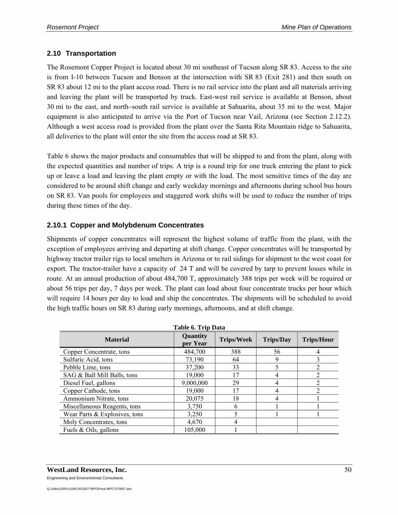
Rosemont Project Mine Plan of Operations
WestLand Resources, Inc. 50 Engineering and Environmental Consultants Q:\Jobs\1000's\1049.05\2007 MPO\Final MPO 070907.doc
2.10 Transportation
The Rosemont Copper Project is located about 30 mi southeast of Tucson along SR 83. Access to the site is from I-10 between Tucson and Benson at the intersection with SR 83 (Exit 281) and then south on SR 83 about 12 mi to the plant access road. There is no rail service into the plant and all materials arriving and leaving the plant will be transported by truck. East-west rail service is available at Benson, about 30 mi to the east, and north–south rail service is available at Sahuarita, about 35 mi to the west. Major equipment is also anticipated to arrive via the Port of Tucson near Vail, Arizona (see Section 2.12.2). Although a west access road is provided from the plant over the Santa Rita Mountain ridge to Sahuarita, all deliveries to the plant will enter the site from the access road at SR 83. Table 6 shows the major products and consumables that will be shipped to and from the plant, along with the expected quantities and number of trips. A trip is a round trip for one truck entering the plant to pick up or leave a load and leaving the plant empty or with the load. The most sensitive times of the day are considered to be around shift change and early weekday mornings and afternoons during school bus hours on SR 83. Van pools for employees and staggered work shifts will be used to reduce the number of trips during these times of the day. 2.10.1 Copper and Molybdenum Concentrates
Shipments of copper concentrates will represent the highest volume of traffic from the plant, with the exception of employees arriving and departing at shift change. Copper concentrates will be transported by highway tractor trailer rigs to local smelters in Arizona or to rail sidings for shipment to the west coast for export. The tractor-trailer have a capacity of 24 T and will be covered by tarp to prevent losses while in route. At an annual production of about 484,700 T, approximately 388 trips per week will be required or about 56 trips per day, 7 days per week. The plant can load about four concentrate trucks per hour which will require 14 hours per day to load and ship the concentrates. The shipments will be scheduled to avoid the high traffic hours on SR 83 during early mornings, afternoons, and at shift change.
Table 6. Trip Data
Material Quantity per Year Trips/Week Trips/Day Trips/Hour
Copper Concentrate, tons 484,700 388 56 4 Sulfuric Acid, tons 73,190 64 9 3 Pebble Lime, tons 37,200 33 5 2 SAG & Ball Mill Balls, tons 19,000 17 4 2 Diesel Fuel, gallons 9,000,000 29 4 2 Copper Cathode, tons 19,000 17 4 2 Ammonium Nitrate, tons 20,075 18 4 1 Miscellaneous Reagents, tons 3,750 6 1 1 Wear Parts & Explosives, tons 3,250 5 1 1 Moly Concentrates, tons 4,670 4 Fuels & Oils, gallons 105,000 1
Rosemont Project Mine Plan of Operations
WestLand Resources, Inc. 51 Engineering and Environmental Consultants Q:\Jobs\1000's\1049.05\2007 MPO\Final MPO 070907.doc
The facility is estimated to produce about 4,670 tpy of moly concentrates as a by-product of the copper concentrates. Moly concentrates will be shipped in bags at the rate of about one truck per day, four days per week. 2.10.2 Sulfuric Acid
Sulfuric acid is a reagent used in the leaching operation; it will be received in special acid tank trucks with a capacity of about 22 to 24 T. Sulfuric acid is available regionally from two smelters in Arizona and one in Northern Mexico. At an annual requirement of about 73,190 T, approximately 64 trips will be required per week, or about 9 trips per day. Note that acid requirements will be reduced significantly after Year 6. Acid receipts will be scheduled seven days per week and during a day shift. The plant can receive and unload about three acid trucks per hour, which will require about three hours per day for sulfuric acid. Acid receipts will be scheduled to avoid high traffic hours and shift changes for safety. 2.10.3 Pebble Lime
Pebble lime is a reagent used for pH control in the grinding and flotation process. Pebble lime will arrive from local sources in bulk in bottom-discharge tank trucks with a capacity of 22 to 24 T. The pebble lime will be pneumatically conveyed from the truck to a storage silo. At an annual requirement of about 37,200 T, approximately 33 trips will be required per week, or about five trips per day. The plant will receive and unload about two trucks of lime per hour, which will require about 3 hours per day. Pebble lime receipts will be scheduled seven days per week during the day and evening, and will avoid high traffic times on SR 83 and shift changes. 2.10.4 SAG and Ball Mill Grinding Balls
SAG and ball mill grinding balls are a major consumable for the grinding circuit. Grinding balls are available from local sources in Arizona and are received in bulk by bottom dump or end dump trucks with a capacity of 24 T. At an annual requirement of about 19,000 T, approximately 17 trips per week, or 4 trips per day, will be required. The receipt of grinding balls will be scheduled during the day, five days per week. The plant can receive and unload about two trucks of grinding medium per hour, which will require about two hours per day for the receipts. Two trucks can be received mid-morning and again mid-afternoon to avoid shift changes and high commute periods on SR 83. 2.10.5 Diesel Fuel
Diesel fuel is a major consumable for the haul trucks. Diesel fuel is available from local suppliers and will be received in tank trucks with a capacity of about 6,000 gallons. At a peak capacity of about 9 million gpy, approximately 29 trips per week, or four trips per day, will be required to receive the fuel. Diesel receipts will be scheduled seven days per week during the day between shift changes. The plant will receive and unload about two trucks per hour, which will require about two hours per day for receiving the diesel into storage.
Rosemont Project Mine Plan of Operations
WestLand Resources, Inc. 52 Engineering and Environmental Consultants Q:\Jobs\1000's\1049.05\2007 MPO\Final MPO 070907.doc
2.10.6 Copper Cathodes
Copper cathode will be produced from the oxide ore in the SX/EW plant. Peak copper cathode production will occur in Year 2 at about 54 tpd; however, this production rate falls to about 10 tpd in Year 5. Based on the peak production year, approximately 19,000 T of cathodes will be produced, which will require about 17 trips per week or 4 trips per day. The copper cathodes will be loaded onto flat-bed trailers with capacities of 22 to 24 T. Approximately two trucks will be loaded and shipped per hour, which will require two hours of shipping per day. Cathode shipments will be scheduled five days per week during the day. 2.10.7 Ammonium Nitrate
Ammonium nitrate will be used for blasting in the pit. It will be received from local sources in bulk by tank truck and pneumatically conveyed into storage silos near the mine. The truck capacity is about 22 to 24 T. The consumption of ammonium nitrate will be about 20,075 T per year, which will require about 18 trips per week, or four trips per day, based on receipts five days per week. Each truck of ammonium nitrate will be received and unloaded into storage in about one hour, for approximately four hours per day. 2.10.8 Miscellaneous Consumables
Miscellaneous quantifiable consumables will consist of reagents used in the process and wear parts used in the crushing and grinding line. Also included will be explosive powder and caps used by the mine. Reagents used in the flotation circuit will be Aero 242 collector, xanthates (SIPX), frother (MIBC), flocculants, sodium hydrosulfide, sodium silicate, burner oil, Dowfroth, and polyglycol. Reagents used in the SX/EW circuit will be LIX extractant, diluent, diatomaceous earth, clay filter media, FC-1100 mist control, guar and cobalt sulfate. Wear parts used in the crusher and grinding line will include primary crusher liners, SAG and ball mill liners, pebble crusher liners, and regrind mill liners. The total amount of reagents that will be used for the flotation plant and SX/EW facility is estimated to be 7.5 million lbs per year (3,700 T). The quantity of crusher and grinding wear parts that will be used is approximately 4.1 million lbs per year (2,050 T). The total quantity of explosives powder and caps used is estimated at 1,200 T per year. Total miscellaneous reagents and consumables that can be quantified will total about 7,000 T per year or about 135 T per week. All miscellaneous reagents and consumables will be shipped to the plant site by small (10- to 15-T) trucks. This requires about 10 trips per week or two trips per day on a five-day per week basis. Consumables such as office supplies, safety equipment, and small tools cannot be quantified, however, these consumables are not considered significant to the transportation study.
Rosemont Project Mine Plan of Operations
WestLand Resources, Inc. 53 Engineering and Environmental Consultants Q:\Jobs\1000's\1049.05\2007 MPO\Final MPO 070907.doc
2.10.9 Miscellaneous Fuels and Lubricants
Miscellaneous fuels and lubricants will include gasoline, motor oils, lubricants, and antifreeze. Used oils and waste antifreeze will also be transported out of the plant for recycling. Consumption of all miscellaneous fuels and lubricants is estimated at 105,000 gallons per year. Fuels and lubricants will be shipped to the plant in bulk by tanker trucks of capacities of 2,000 to 6,000 gallons or in barrels. All miscellaneous fuels and lubricants will average 2,000 gallons per week or one trip per week. 2.10.10 Employees
The work force for the Rosemont Project is estimated at 494 employees. Approximately 85 will be salaried, technical, and administrative personnel and are scheduled to work five days per week on day shift only. The shift schedule will be 8:00 a.m. to 5:00 p.m., Monday through Friday. In addition, approximately 38 maintenance employees will work day shift only, Monday through Friday. Their scheduled shift will be 7:00 a.m. to 4:00 p.m. Another 371 employees will work rotating 12-hour shifts from 6:00 a.m. to 6:00 p.m. One hundred and nine workers will be on day shift, 77 on night shift, and 185 will be scheduled off at any one time. The shift-change hours will start before 6:00 a.m. with the arrival of a new shift. Maintenance employees will start arriving before 7:00 a.m. after the night shift employees have left. The administrative and technical employees will start arriving before 8:00 a.m. At the end of the day, maintenance employees will leave at 4:00 p.m., administrative and technical employees at 5:00 p.m. and the shift operators at 6:00 p.m.
For the transportation study, it is assumed that van pooling will be provided with an average of five people per car. This will result in 47 trips arriving and 15 trips leaving in the morning. At the evening shift change, 47 trips will be leaving and 15 arriving. The shift change hours will see the highest volume of traffic in and out of the plant. At times, traffic will be under 10 trips per hour. 2.10.11 Safety Evaluation
Access to the plant will be by federal and state highways up to the primary access road. The access road will be 3.7 mi long with no sharp turns or grades of more than 8%. The access road will be two-lane, 14-ft wide each, with 4-ft shoulders. Drainage will be provided on both sides of the road to control stormwater runoff. The road surface will be compacted ADOT aggregate (Class 2), 8 in thick. The road will be designed for travel at 35 mph. The intersection of the plant access road and SR 83 will be upgraded to include turnout and acceleration/deceleration lanes on SR 83 approaching from either direction and leaving in either direction. Shift change will be staggered to spread the traffic over a three-hour period for arriving and departing traffic. Van pools will also be used to reduce the number of vehicles entering and leaving the plant at shift change. Major shipments, such as copper concentrates and sulfuric acid, will be scheduled to avoid shift changes and high volume traffic times for SR 83.
Rosemont Project Mine Plan of Operations
WestLand Resources, Inc. 54 Engineering and Environmental Consultants Q:\Jobs\1000's\1049.05\2007 MPO\Final MPO 070907.doc
Employees arriving and departing the plant at shift change will create the highest density at 23 to 32 trips per hour. Trip densities during the balance of the day will be under 10 trips per hour, which can comfortably accommodate the miscellaneous traffic from vendors, visitors, and deliveries of common warehouse items. 2.11 Waste Management
2.11.1 On-Site Management of Wastes
Rosemont Copper will manage materials on site to minimize the amount of waste created and to ensure wastes do not become mixed, contaminated, or otherwise mismanaged. A summary of these measures is provided below. Additional information is provided by Tetra Tech (2007i). 2.11.1.1 Solid Waste
As part of the on-site permitting effort, Rosemont Copper will file for a solid waste facility permit and include the facility in the area-wide permitting effort allowed by ARS §49-243.P. The facility is planned to cover approximately 1.5 ac and will be managed using trenching and cover techniques. The facility will be managed for on-site, non-hazardous wastes, and will not accept any off-site wastes. The primary disposal activities on site will include but may not be limited to the following:
• Demolition and construction debris • Non-putrescible materials • Waste from maintenance and operations meeting the definition of inert or non-hazardous
such as respirator filters, gloves, boxes, non-recylable packaging material, air filters, hoses, and piping
This permit must meet the requirements of a non-municipal solid waste facility. 2.11.1.2 Hazardous Waste
Hazardous wastes that may be generated at the facility include, but may not be limited to, the following:
• Waste paint materials such as thinners
• Chemical wastes such as acetone from the on-site laboratory
• Residue wastes from containers or cans
As part of the permitting effort, Rosemont Copper will file for a hazardous waste identification number from the EPA and register as a generator of hazardous waste with ADEQ and PCDEQ. Proper management of wastes should allow Rosemont Copper to have a status of Conditionally Exempt Small Quantity Generator (CESQG) of hazardous wastes. However, in the event that it becomes necessary to
Rosemont Project Mine Plan of Operations
WestLand Resources, Inc. 55 Engineering and Environmental Consultants Q:\Jobs\1000's\1049.05\2007 MPO\Final MPO 070907.doc
manage quantities of waste in excess of the CESQG threshold, Rosemont Copper will be in compliance by following all rules associated with proper management of waste on a larger scale. Waste will be stored on site and inspected as required by the hazardous waste regulations. As part of these pollution prevention activities, Rosemont Copper materials entering the site will be examined to determine if they have the potential to create hazardous waste. If they do, non-hazardous substitutes will be sought. The operations will be examined on an on-going basis to ensure that hazardous substances are eliminated whenever possible. 2.11.1.3 Sanitary Waste
Sanitary waste at the Project will be handled by septic systems, with leach fields located in the vicinity of each building. During the construction phase, and where necessary during operations, portable toilets will be used in various locations throughout the plant and mine sites. Sanitary wastes will be collected periodically by a commercial sanitation service and removed for disposal off site. 2.11.1.4 Specific Waste Management Activities
In general, waste will be managed in dumpsters or other appropriate containers. All containers will be covered or weighted to prevent blowing trash. Trash from office areas will be bagged. A waste disposal company will be contracted as necessary to manage wastes other than debris or construction and demolition wastes. 2.11.1.4.1 Scrap Metal
Scrap metal will be managed to facilitate recycling, with separate roll-off dumpsters located near points of use. Contracts with scrap metal recyclers will be established for on-going recycling activities. In the event recycling becomes impossible or otherwise impracticable (i.e., scrap prices drop or scrap prices become so high there are not enough recyclers), scrap metal will be stockpiled near the solid waste facility for bulk recycling. 2.11.1.4.2 White Paper
The Department of Economic Security (DES) provides a recycling service for white paper. Unfortunately, the pick-up service DES offers is confined to the Tucson area. At this point, Rosemont Copper plans to drop off white paper waste at the DES offices on an as-needed basis to minimize the amount of paper disposed on site. Rosemont Copper will continue to investigate additional opportunities for white paper management. 2.11.1.4.3 Grease
Grease associated with the hoisting, milling, and other operational equipment will be placed into drums or other bulk containers suitable for recycling. If the grease is not suitable for recycling, the contained waste
Rosemont Project Mine Plan of Operations
WestLand Resources, Inc. 56 Engineering and Environmental Consultants Q:\Jobs\1000's\1049.05\2007 MPO\Final MPO 070907.doc
will be sent off site for disposal. While on site, the containers will be managed in an area that will provide secondary containment. 2.11.1.4.4 Used Oil
Used oil from maintenance activities will be managed in bulk containers with secondary containment to ensure there is no release to the environment. Only oil acceptable for recycling will be placed in the bulk containers. Used oil not acceptable for recycling will be placed in drums for proper disposal. 2.11.1.4.5 Batteries
Lead acid batteries will be returned to the vendor for recycling or shipped off site to a recycler. While they are stored on site, they will be managed in an area protected from stormwater and will have secondary containment. Nickel-Cadmium (NiCd) batteries will be stored for recycling by a local vendor. While on site, they will be managed in drums or boxes suitable for storage. Lithium batteries will also be stored for recycling in appropriate containers. 2.11.1.4.6 Tires
There are two opportunities for disposing tires from registered vehicles and that are less than 3 ft in diameter. The vendor will remove the waste tires from the property for appropriate disposal or recycling; or, a waste handler will be contracted to remove the tires for appropriate disposal or recycling. At mining sites, the vendors who supply the tires generally remove them for recycling or disposal. Rosemont Copper will contract with vendors or waste haulers who can appropriately manage waste tires smaller than 3 ft in diameter. Tires that are greater than 3 ft in diameter are eligible for on site disposal (AAC Title 18 Chapter 13.) This code allows operators to bury mining waste tires in an on site cell if they meet specific requirements. Once placed in the cell, the tires will be covered with a minimum of 6 in of material within 50 days of placement. Once the cell is full, at least 3 ft of final cover will be placed over the cell within 180 days. Rosemont Copper will file the required annual reports, keep records and provide any certifications as required by the regulations. At this time, Rosemont Copper is investigating the potential for reuse of these tires and will continue to seek contracts for beneficial uses of mining tires. As appropriate, tires may also be used for erosion control or structural fill. If alternatives to burial exist, Rosemont Copper will review them and manage the tires accordingly.
Rosemont Project Mine Plan of Operations
WestLand Resources, Inc. 57 Engineering and Environmental Consultants Q:\Jobs\1000's\1049.05\2007 MPO\Final MPO 070907.doc
2.11.1.4.7 Lead Flake and Anodes
The electowinning process uses lead anodes to provide the necessary electrolytic conditions for copper plating. During this process, the anodes degrade creating a lead flake that falls into the electrowinning cells. This flake and the degraded anodes are a valuable commodity when managed properly and recycled. On-site management of these materials will consist of placing the flake into a roll-off or other container designed to contain the material for transport to a lead smelter for recycling. Anodes will also be stored in containers to facilitate shipment for recycling. 2.11.1.4.8 HDPE Materials
Piping and liner materials made from HDPE may be recycled if managed appropriately on site. Rosemont Copper plans to identify a recycler of these materials and utilize them accordingly. If HDPE piping and liner grade materials are not recyclable, Rosemont Copper will dispose of these materials in the on-site waste management facility. 2.11.1.4.9 Wood and Other Packing Materials
Much of the material delivered to the Rosemont site will be on wooden pallets, packaged in cardboard, or wrapped in plastic. Many of these items will be recycled in Tucson. Rosemont Copper plans to recycle as much of the shipping and packaging material received at the site as possible, utilizing businesses in Tucson and the surrounding communities. 2.11.2 Offsite Shipment of Wastes
When off-site disposal is necessary, Rosemont Copper will manage materials as required by the Resource Conservation and Recovery Act (RCRA) and Department of Transportation (DOT) regulations. All shipments will be properly marked and manifested (using manifests or bills of lading), and characterizations of shipped waste materials will be available. 2.11.2.1 Solid Waste
Materials that may not be hazardous waste but are not appropriate for disposal on site will be shipped off site for recycling and/or disposal. Materials such as used oil and scrap metal will be shipped to recyclers that are audited either by Rosemont Copper personnel or by regulatory agencies. Other materials, such as grease that may not have available markets for recycling, may need to be disposed off site rather than recycled. 2.11.2.2 Hazardous Waste
Materials classified as hazardous waste will be shipped off site for destruction or disposal. Materials such as contaminated grease, unused chemicals, paint related materials, and reagent that may be classified as hazardous waste will be shipped off site. Rosemont Copper plans to dispose of these materials using the most permanent and practicable disposal method available.
Rosemont Project Mine Plan of Operations
WestLand Resources, Inc. 58 Engineering and Environmental Consultants Q:\Jobs\1000's\1049.05\2007 MPO\Final MPO 070907.doc
2.12 Construction Phase
The construction phase for the on-site portions of the Rosemont Copper Project will last about 18 months and will begin as soon as a Record of Decision is received and all necessary permits are in place. Some off-site construction activities will begin earlier, with the appropriate permits. The off-site activities include the fresh water well development, the fresh-water pipeline and pumping stations, and the 138 kV transmission line. These activities are located on patented land or state trust land on the western side of the Santa Rita Mountains. The description of the transportation requirements during construction addresses the traffic on SR 83 and the eastern access road to the mine site and process facilities. 2.12.1 Transportation
Transportation during the construction phase will involve construction personnel arriving and leaving the site and the delivery of the required equipment and materials. Access to the site will be by federal and state highways up to the east access road from SR 83. The intersection of SR 83 and the plant access road will be upgraded with turn-out lanes and acceleration/deceleration lanes as early as possible. Specifically, during and before traffic volume increases due to construction activities. The work schedule during construction is expected to be ten hours per day, five days per week, with no activity on weekends. Occasional overtime may occur on Saturdays to maintain the construction schedule. Shift times will start at 6:00 a.m. to 4:30 p.m., with a half-hour lunch period. During the summer months, work may start an hour earlier to take advantage of the coolest time of day. 2.12.2 Personnel
A total of 2.0 million construction craft worker-hours are expected for the on-site work. Employee levels will increase to about 125 in the second month and will peak at about 900 in the seventh month. Peak employment will be maintained for about five months, then start declining to about 225 in month 16 and 45 in the last month. The majority of the construction crews are expected to come from the Tucson and Green Valley areas; however, some may also come from the Sonoita area and points south. Crews will be bussed from staging areas along I-10 to the north and Sonoita to the south in order to avoid increased traffic along SR 83 between I-10 and Sonoita. The staging areas will be determined when the boarding locations of the riders are known. The bus traffic will peak at about 20 to 26 trips between the sixth month and the thirteenth month of construction, based on bus loads of about 35 people. In addition to the craft labor, each contractor on site and the construction management contractor will have supervisory staff arriving at the plant. The construction management contractor is expected to have a supervisory and office staff of about 47 people and will require about 12 trips into and out of the plant, based on an average carpool of four people per vehicle. Approximately 11 additional contractors will be on site during the peak months with total supervisory and office staff of about 57 people. This will require about 28 trips into and out of the plant, based on about two people per vehicle.
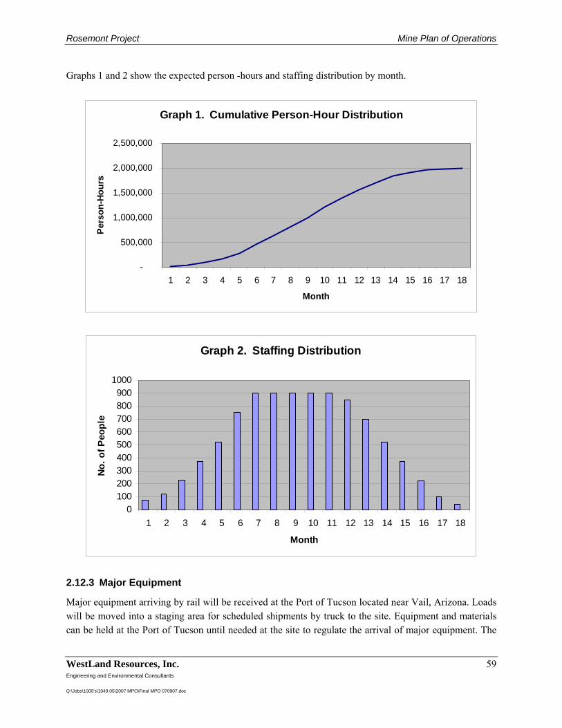
Rosemont Project Mine Plan of Operations
WestLand Resources, Inc. 59 Engineering and Environmental Consultants Q:\Jobs\1000's\1049.05\2007 MPO\Final MPO 070907.doc
Graphs 1 and 2 show the expected person -hours and staffing distribution by month.
Graph 1. Cumulative Person-Hour Distribution
-
500,000
1,000,000
1,500,000
2,000,000
2,500,000
1 2 3 4 5 6 7 8 9 10 11 12 13 14 15 16 17 18
Month
Pers
on-H
ours
Graph 2. Staffing Distribution
0100200300400500600700800900
1000
1 2 3 4 5 6 7 8 9 10 11 12 13 14 15 16 17 18
Month
No. o
f Peo
ple
2.12.3 Major Equipment
Major equipment arriving by rail will be received at the Port of Tucson located near Vail, Arizona. Loads will be moved into a staging area for scheduled shipments by truck to the site. Equipment and materials can be held at the Port of Tucson until needed at the site to regulate the arrival of major equipment. The
Rosemont Project Mine Plan of Operations
WestLand Resources, Inc. 60 Engineering and Environmental Consultants Q:\Jobs\1000's\1049.05\2007 MPO\Final MPO 070907.doc
logistics coordinator from the construction management contractor will coordinate the shipments of major equipment and materials by truck to avoid arrival of more materials at the site than can reasonably be handled. These controls will allow delivery of the materials to site when needed and stagger the shipments to avoid excessive traffic. The first major equipment to arrive at the site will be the haul trucks, shovels, dozers, graders, drills and water trucks which will be used to start the pre-development mining. Haul trucks arrive in about seven truckloads for each truck and will be assembled on site. A total of 22 haul trucks will be purchased and delivered to site during the construction period, which will require 154 truck loads. Mine shovels will arrive in about 19 truckloads per shovel and will also be assembled on site. Three shovels will be purchased and delivered during construction, requiring about 57 truck loads. Two large, 33-yard front-end loaders will be purchased and will arrive in 26 truckloads for assembly on site. A total of four rotary and percussion drills will be purchased and will arrive on about six trucks. A total of seven crawler and rubber-tired dozers will be purchased and will arrive in about 19 truck loads. Two water trucks will be purchased and will arrive on site in about four truck loads. There will be three graders purchased which will arrive on individual shipments of one grader per truck. The 43 complete pieces of mine equipment will be delivered over a 16-week period starting in the second month and will average about 17 trucks per week for a four-month period. This will average three to four trucks per day during this period. A summary of the major mine equipment shipments are shown in Table 7.
Table 7. Mine Equipment
Mine Equipment Number Items/
Shipment Total
Shipments Duration
Weeks Trucks/ Week
Haul Trucks 22 7 154 Shovels 3 19 57 Front End Loader 2 13 26 Drills 4 1.5 6 Dozers 5 3 15 RT Dozers 2 2 4 Graders 3 1 3 Water Trucks 2 2 4 TOTALS 43 269 16 17
The major process equipment is summarized in Table 8. Major equipment quantities are tabulated, and the total number of truck shipments to the site is estimated to be 624. Major process equipment will be delivered over a 36-week period starting in the fifth month. Assuming the shipments are distributed evenly, the average number of shipments per week will be about 18, or a peak of four shipments per day.
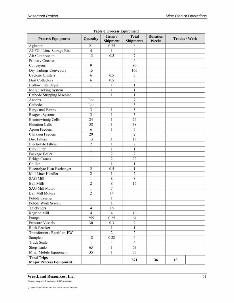
Rosemont Project Mine Plan of Operations
WestLand Resources, Inc. 61 Engineering and Environmental Consultants Q:\Jobs\1000's\1049.05\2007 MPO\Final MPO 070907.doc
Table 8. Process Equipment
Process Equipment Quantity Items / Shipment
Total Shipments
Duration Weeks Trucks / Week
Agitators 21 0.25 6 ANFO / Lime Storage Bins 4 1 4 Air Compressors 13 0.5 7 Primary Crusher 1 6 Conveyors 9 80 Dry Tailings Conveyors 15 166 Cyclone Clusters 6 0.5 3 Dust Collectors 6 0.5 3 Hollow Flite Dryer 1 1 1 Moly Packing System 1 1 1 Cathode Stripping Machine 1 1 1 Anodes Lot 7 Cathodes Lot 3 Barge and Pumps 3 1 3 Reagent Systems 3 1 3 Electrowinnig Cells 24 1 24 Flotation Cells 38 1 38 Apron Feeders 6 1 6 Clarkson Feeders 29 2 Disc Filters 13 1 13 Electrolyte Filters 2 1 2 Clay Filter 1 1 1 Package Boiler 1 2 2 Bridge Cranes 11 2 22 Chiller 1 1 1 Electrolyte Heat Exchanger 2 0.5 1 Mill Liner Handler 2 1 2 SAG Mill 1 8 8 Ball Mills 2 8 16 SAG Mill Motor 1 7 Ball Mill Motors 2 14 Pebble Crusher 1 1 Pebble Wash Screen 1 1 Thickeners 4 16 Regrind Mill 4 4 16 Pumps 255 0.25 64 Pressure Vessels 30 0.3 9 Rock Breaker 1 1 1 Transformer / Rectifier -EW 1 2 2 Samplers 18 0.28 6 Truck Scale 1 4 4 Shop Tanks 63 1 63 Misc. Mobile Equipment 35 1 35 Total Trips Major Process Equipment 671 36 19
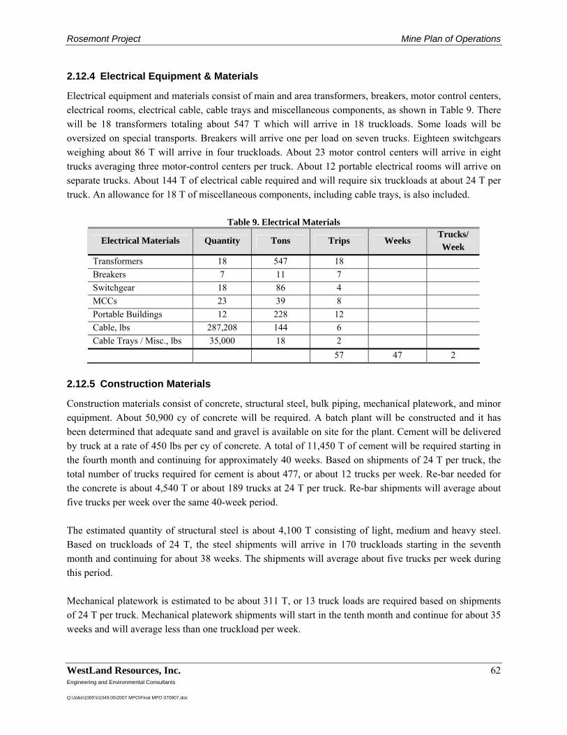
Rosemont Project Mine Plan of Operations
WestLand Resources, Inc. 62 Engineering and Environmental Consultants Q:\Jobs\1000's\1049.05\2007 MPO\Final MPO 070907.doc
2.12.4 Electrical Equipment & Materials
Electrical equipment and materials consist of main and area transformers, breakers, motor control centers, electrical rooms, electrical cable, cable trays and miscellaneous components, as shown in Table 9. There will be 18 transformers totaling about 547 T which will arrive in 18 truckloads. Some loads will be oversized on special transports. Breakers will arrive one per load on seven trucks. Eighteen switchgears weighing about 86 T will arrive in four truckloads. About 23 motor control centers will arrive in eight trucks averaging three motor-control centers per truck. About 12 portable electrical rooms will arrive on separate trucks. About 144 T of electrical cable required and will require six truckloads at about 24 T per truck. An allowance for 18 T of miscellaneous components, including cable trays, is also included.
Table 9. Electrical Materials
Electrical Materials Quantity Tons Trips Weeks Trucks/ Week
Transformers 18 547 18 Breakers 7 11 7 Switchgear 18 86 4 MCCs 23 39 8 Portable Buildings 12 228 12 Cable, lbs 287,208 144 6 Cable Trays / Misc., lbs 35,000 18 2 57 47 2
2.12.5 Construction Materials
Construction materials consist of concrete, structural steel, bulk piping, mechanical platework, and minor equipment. About 50,900 cy of concrete will be required. A batch plant will be constructed and it has been determined that adequate sand and gravel is available on site for the plant. Cement will be delivered by truck at a rate of 450 lbs per cy of concrete. A total of 11,450 T of cement will be required starting in the fourth month and continuing for approximately 40 weeks. Based on shipments of 24 T per truck, the total number of trucks required for cement is about 477, or about 12 trucks per week. Re-bar needed for the concrete is about 4,540 T or about 189 trucks at 24 T per truck. Re-bar shipments will average about five trucks per week over the same 40-week period. The estimated quantity of structural steel is about 4,100 T consisting of light, medium and heavy steel. Based on truckloads of 24 T, the steel shipments will arrive in 170 truckloads starting in the seventh month and continuing for about 38 weeks. The shipments will average about five trucks per week during this period. Mechanical platework is estimated to be about 311 T, or 13 truck loads are required based on shipments of 24 T per truck. Mechanical platework shipments will start in the tenth month and continue for about 35 weeks and will average less than one truckload per week.
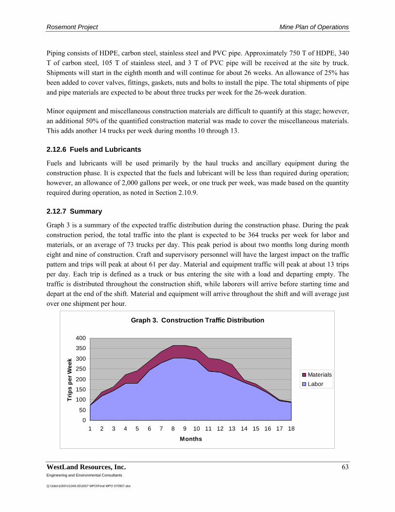
Rosemont Project Mine Plan of Operations
WestLand Resources, Inc. 63 Engineering and Environmental Consultants Q:\Jobs\1000's\1049.05\2007 MPO\Final MPO 070907.doc
Piping consists of HDPE, carbon steel, stainless steel and PVC pipe. Approximately 750 T of HDPE, 340 T of carbon steel, 105 T of stainless steel, and 3 T of PVC pipe will be received at the site by truck. Shipments will start in the eighth month and will continue for about 26 weeks. An allowance of 25% has been added to cover valves, fittings, gaskets, nuts and bolts to install the pipe. The total shipments of pipe and pipe materials are expected to be about three trucks per week for the 26-week duration. Minor equipment and miscellaneous construction materials are difficult to quantify at this stage; however, an additional 50% of the quantified construction material was made to cover the miscellaneous materials. This adds another 14 trucks per week during months 10 through 13. 2.12.6 Fuels and Lubricants
Fuels and lubricants will be used primarily by the haul trucks and ancillary equipment during the construction phase. It is expected that the fuels and lubricant will be less than required during operation; however, an allowance of 2,000 gallons per week, or one truck per week, was made based on the quantity required during operation, as noted in Section 2.10.9. 2.12.7 Summary
Graph 3 is a summary of the expected traffic distribution during the construction phase. During the peak construction period, the total traffic into the plant is expected to be 364 trucks per week for labor and materials, or an average of 73 trucks per day. This peak period is about two months long during month eight and nine of construction. Craft and supervisory personnel will have the largest impact on the traffic pattern and trips will peak at about 61 per day. Material and equipment traffic will peak at about 13 trips per day. Each trip is defined as a truck or bus entering the site with a load and departing empty. The traffic is distributed throughout the construction shift, while laborers will arrive before starting time and depart at the end of the shift. Material and equipment will arrive throughout the shift and will average just over one shipment per hour.
Graph 3. Construction Traffic Distribution
0
50
100
150
200
250
300
350
400
1 2 3 4 5 6 7 8 9 10 11 12 13 14 15 16 17 18
Months
Trip
s pe
r Wee
k
MaterialsLabor
Rosemont Project Mine Plan of Operations
WestLand Resources, Inc. 64 Engineering and Environmental Consultants Q:\Jobs\1000's\1049.05\2007 MPO\Final MPO 070907.doc
2.13 Site Operations Security and Public Safety
2.13.1 Security
In order for the Rosemont operations to run smoothly, it is important that the site be secure. Theft and vandalism could potentially have a negative effect on worker safety and on operating efficiency. Therefore, access to the site will be controlled by fencing, security patrols and by limiting locations for officially entering and leaving the property. Operations will be conducted around the clock and guard buildings will be located at the official entrances. Other guards will conduct mobile patrols of the perimeter fence to insure that no one is accessing the site unlawfully. Signs will be posted along the fence and at strategic locations along roads warning people that the entering the site is prohibited. 2.13.2 Public Safety
In addition to protecting the site from potential vandalism or theft, it is also important to protect the public from interfacing with the mine operations and to prevent potential injury. Hazards of a typical mining operation include but are not limited to: traumatic injury from large equipment, getting entangled in machinery, driving over steep embankments, slipping or falling on uneven ground or slippery surfaces, encountering high voltage electricity, exposure to chemicals or reagents while not wearing proper personal protective equipment, and exposure to loud noises while not wearing hearing protection. Employees working at the site are required to receive specific training in accordance with Mine Safety and Health Administration (MSHA) rules, covering all aspects of site safety, whereas recreationists will likely have no such training and may not recognize the hazards. Therefore, it is imperative that access is controlled and that trespassing rules are enforced. The same fencing, patrols and signage discussed in Section 2.13.1 will serve to warn recreationists and others in the area of potential dangers. In addition, employees will be trained to be aware of trespassers in the course of their normal duties and report any suspicious activity to the safety and property departments. The facilities have been designed to minimize the need for visitors to drive or walk in hazardous areas. Most visitors, vendors and salespeople will come and go from the administration building or an administrative area within the warehouse/receiving building located near the guard house at the entrance of the facility. Supply route drivers will receive site orientation training and be familiarized with their specific loading/unloading locations and procedures. 2.13.3 Fire and Emergency Planning
Planning for emergencies will be an important part of establishing operations for the Rosemont Project. Several types of plans will be prepared prior to start up. These plans will include a Spill Prevention Control and Countermeasure (SPCC) Plan, an Emergency Response and Contingency Plan, a Stormwater Pollution Prevention Plan (SWPPP), a Fire Plan, and others. These plans will identify emergency preparedness and emergency contact protocols for any conceivable situation.
Rosemont Project Mine Plan of Operations
WestLand Resources, Inc. 65 Engineering and Environmental Consultants Q:\Jobs\1000's\1049.05\2007 MPO\Final MPO 070907.doc
As project planning continues to develop, the specifics of the emergency planning process will also advance. In addition, extensive training of personnel and the availability of appropriate equipment and supplies will insure a successful emergency management program. Staffing for the Rosemont Project includes safety, industrial hygiene, and environmental technical professionals. Some of the facilities and equipment for emergency planning include: a fully equipped environmental sampling and spill response station, Resource Conservation and Recovery Act (RCRA)-compliant waste storage and accumulation areas, safety and training building, an ambulance, and a fire truck. Of special concern will be preventing wildfires. Mine vehicles will be equipped with, at a minimum, fire extinguishers, shovels and first aid kits. Policies, such as prohibiting parking on top of vegetation, and properly disposing of cigarette butts, will be established and enforced to minimize fire potential. 2.13.3.1 Water and Chemical Supply Systems
Fresh water for the Rosemont Project will be supplied from dedicated wells located on the property. Water from the wells will report to the fresh water tank. Water will be pumped from the fresh water tank by vertical turbine pumps. It will travel through a common pipeline and a system of three water booster tanks and horizontal centrifugal pump systems, installed in series, to the plant area fresh/fire water tank. Fresh water and fire water will be supplied from the fresh/fire water tank to the facility by gravity. The fire water distribution system is located in the mill site area and the foam fire system in the solvent extraction area. 2.13.3.2 Emergency Lighting and Exit Signs
Adequate and reliable illumination will be installed and maintained for all exits. Battery powered back up must provide a minimum of 60 minutes of illumination and will be standard for all emergency lighting and exit signs. Maintenance inspections will be conducted on a monthly basis. Emergency and exit lighting systems will be tested annually. 2.13.3.3 Fire and Smoke Alarms
Fire and smoke alarms will be installed in all employee work areas. Systems and components will receive inspection monthly. Annual testing and maintenance will be conducted for systems and components. Records of inspections will be kept on site for a minimum of 5 years. 2.13.3.4 Fire Extinguishers
The National Fire Protection Association (NFPA) established NFPA 10, which is the Standard for Portable Fire Extinguishers. NFPA 10 mandates the type, size, placement, and minimum number of extinguishers required for each building. Fire extinguishers will be installed in accordance with this standard.
Rosemont Project Mine Plan of Operations
WestLand Resources, Inc. 66 Engineering and Environmental Consultants Q:\Jobs\1000's\1049.05\2007 MPO\Final MPO 070907.doc
2.13.3.5 Standpipe Fire Hose Stations
In addition to portable fire extinguishers, standpipe fire hose stations will be provided for defend-in-place fire protection. This equipment is designed to protect individuals from initial developing fires and will be installed at mine plant site areas where fire response time exceeds five minutes.
Rosemont Project Mine Plan of Operations
WestLand Resources, Inc. 67 Engineering and Environmental Consultants Q:\Jobs\1000's\1049.05\2007 MPO\Final MPO 070907.doc
3 Resource Protection and Control Plans
3.1 Groundwater Protection Plan
Groundwater quality in Arizona is regulated under ADEQ’s APP program. Rosemont Copper has initiated the APP process, and this section describes, in general, the groundwater protection components of the permit that will be implemented at the Project. A more detailed discussion of groundwater protection measures at the Project is provided by Tetra Tech (2007e). The following components were incorporated into the Project design to ensure compliance with APP’s BADCT requirements:
• Isolation and containment of process waters • Primary and secondary containment structures, such as double liners in process impoundments
and elevated, double-walled, or contained tanks • Overflow protection and spill and leak detection systems • Management of stormwater runoff to reduce sediment loads in stormwater discharges to
premining conditions • Management of process water for zero discharge
The groundwater protection design is enhanced with significant and ongoing geochemical analysis of the waste rock and tailings material, and the planned development of a groundwater monitoring program in compliance with APP requirements. 3.1.1 Potentially Discharging Facilities
3.1.1.1 Ponds
A description of ponds used in the surface water management program at the Project is provided in Section 2.9. These ponds include:
• The PWTS Pond (also referred to as the reclaim water pond) • PLS, raffinate, and stormwater ponds associated with the heap leach facility • The attenuation pond upgradient of the central drain • A variety of smaller stormwater ponds and sediment traps designed to control sediment
discharges from the Project. 3.1.1.2 Leach Pad
The leaching and SX/EW operations at the Rosemont Project will be consistent with other modern operations in Arizona that utilize lined leach pads. Drip emitters will minimize the potential for evaporation or overspray of leaching solutions. This will conserve groundwater and protect the ground and vadose zones that surround the leach pad. Solutions will be collected in ponds that are constructed
Rosemont Project Mine Plan of Operations
WestLand Resources, Inc. 68 Engineering and Environmental Consultants Q:\Jobs\1000's\1049.05\2007 MPO\Final MPO 070907.doc
with double-liners and a leak detection system. The ponds will be operated to maintain at least three ft of freeboard above the normal operating range. In addition, stormwater from the leach pad area will be collected in a lined stormwater pond. The ponds associated with the leach circuit will be sized so that all solutions can be captured for a 24-hour leach facility drain down in case of power failure or process upsets. The ponds and heap leach pad facilities will meet the prescriptive BADCT requirements for these types of facilities as regulated by ADEQ. Specific operating controls as discussed in ADEQ’s BADCT manual are incorporated into the designs. Those controls include:
• Three ft of operating freeboard in addition to solutions management capabilities equal to those described above
• Double liners placed on low permeability geosynthetic clay liner (GCL) with leak detection sumps and capability to add a pump as necessary
• Overflow to a lined facility capable of managing a 100-year, 24-hour storm event, with a minimum of three ft of freeboard
• The leach pad is lined and placed on a low-permeability GCL with piping and drain fill above the liner to ensure drainage is maintained and hydraulic head on the liner is limited
• The prepared pad for leach material is graded to drain toward the ponds or lined collection ditch
• A collection ditch that surrounds the entire heap leach pad, drains to the PLS ponds, and provides secondary containment for a portion of the PLS piping system.
All PLS in the process ponds will be routed to the SX plant for processing. Each flow system is isolated, recycled, and contained in this process. The plant will be designed to be non-discharging and will be operated in a manner that isolates process solutions from the environment. 3.1.1.3 Dry-Stack Tailings Facility
As described above, the Rosemont Project will utilize dry-stack tailings technology. The advantages of dry tailings disposal over conventional tailings is the elimination of an engineered embankment and seepage containment system, the maximization of water conservation, and the minimization of water make-up requirements. Additionally, dry tailings will be confined to the Barrel Canyon drainage. Section 2.9 describes a series of surface water management features, such as diversions and ponds, which are incorporated into the tailings facility design to minimize stormwater runon and infiltration into the dry-stack tailings. As such, the features will also function to minimize impacts to groundwater. Tailings characterization was performed on two samples that were available from metallurgical testing (Tetra Tech, 2007a). Acid-base accounting (ABA), leachate analysis, whole rock analysis, and on-going
Rosemont Project Mine Plan of Operations
WestLand Resources, Inc. 69 Engineering and Environmental Consultants Q:\Jobs\1000's\1049.05\2007 MPO\Final MPO 070907.doc
kinetic testing all strongly suggest that the tailings material will have a very limited potential for leaching metals and will have no significant risk of producing acid. Additional testing is currently being performed on a third test sample. Additional geochemical studies are ongoing. Seepage and stability analyses are also provided in the Dry Tailings Facility Design Report (Tetra Tech, 2007b). 3.1.1.4 Waste Rock Storage
As described above, waste rock deposition will be confined to the Barrel Canyon drainage, and a series of stormwater controls (Section 2.9) will function to minimize the discharge of sediments or other pollutants from the waste rock storage areas. Geochemical testing completed to date indicates that only 3% of the waste rock samples show characteristics of being potentially acid generating (PAG). In addition to the material characterized as PAG, approximately 23% of the samples tested resulted in an “uncertain” acid generating potential. Both the samples identified as PAG and those that have uncertain acid generating potential appear to occur in a relatively limited area of the pit. As discussed in the Baseline Geochemical Characterization (Tetra Tech, 2007a), additional samples are being collected to cover a broad spatial distribution in an effort to define an exact area of concern. However, based on currently available data, it appears the PAG material may be managed through proper placement within the waste rock storage area. Once all test work is completed, a mine waste management plan will be developed so that any materials that may be acid generating or could cause an impact to groundwater or surface water will be placed where they will not be exposed to water. A site-wide geochemical model is planned including possible mitigation and management strategies should ARD issues arise. 3.1.1.5 Open Pit
The hydrogeology and geochemistry of the open pit are being investigated to determine if passive containment will be achieved and maintained without management, or if discharge will need to be managed in the long term. Hydrogeologic and geochemical modeling is planned for this facility to verify the appropriate management and permitting scenario. A series of geochemical tests were performed on samples that will be exposed to potential leaching at closure. Some samples were specifically targeted to areas within the open pit that would be exposed at closure. These samples will be used in the modeling to determine the potential overall water condition in the pit. The results available to date illustrate that, in the case of the samples available for analysis, and suspected as being exposed at closure, the acid generating potential will be limited. Humidity cell testing has been ongoing and will continue. As additional results become available these assumptions will be reviewed and updated.
Rosemont Project Mine Plan of Operations
WestLand Resources, Inc. 70 Engineering and Environmental Consultants Q:\Jobs\1000's\1049.05\2007 MPO\Final MPO 070907.doc
3.1.1.6 Concentrator, SX/EW, and Other Process and Maintenance Facilities
Design plans are currently underway for the operational and maintenance facilities located at the plant site. These facilities are specifically designed to manage solutions so they are not discharged into the environment. Typical design criteria for tanks, concrete-floored buildings with curbs, and concrete sumps will be used to ensure the facilities are non-discharging. Pipelines will have a rigorous inspection program, be instrumented, or be double-walled so the non-discharging criteria can be applied. Finally, larger tanks will be constructed with secondary containment which will also be designed to be non-discharging. 3.1.1.7 Material Stockpiles
There are two types of stockpiles anticipated at this facility: those related to the process and those designed to contain growth media for reclamation purposes. The process related stockpiles will meet the definition of temporary storage and be managed inside the process areas. The growth media stockpiles will consist of soil and grubbed material that will be available for reclamation activities. Neither type of stockpile will meet the definition of a discharging facility as defined by the APP program. 3.1.2 Pollutant Management Area (PMA)
3.1.2.1 PMA
As described in the ARS §49-244.1 and the APP program, the Pollutant Management Area (PMA) is the limit projected in the horizontal plane on which pollutants are or will be placed. The PMA is an imaginary line circumscribing potentially discharging facilities or activities at the site. Figure 3-1 depicts the currently proposed PMA in relation to the facilities currently under evaluation. It is anticipated that the PMA boundary depicted may be modified as plans become better defined. The PMA boundary defined herein corresponds to the currently planned facilities and activities. 3.1.2.2 Point of Compliance (RP), Hydrologic Characterization (HC), and Pit
Characterization (PC) Wells
Based on the current proposed PMA, the proposed point of compliance (RP) monitor wells, as described in ARS §49-244.2, are shown in Figure 3-1. In addition to the RP wells, hydrogeologic characterization (HC), and pit characterization (PC) wells are also shown on Figure 3-1. The PC wells located on private land are being installed prior to the issuance of the APP permit to characterize hydrogeologic conditions in the vicinity of the pit, to monitor ambient groundwater quality, and to determine groundwater characteristics for evaluation of pit dewatering requirements. The RP and HC wells (on USFS lands) are planned for installation to document ambient groundwater quality, monitor groundwater quality over time, and to define the hydrogeologic characteristics of the planned operational areas.
Rosemont Project Mine Plan of Operations
WestLand Resources, Inc. 71 Engineering and Environmental Consultants Q:\Jobs\1000's\1049.05\2007 MPO\Final MPO 070907.doc
It is anticipated that some or all of the PC and HC wells will remain in place during the pre-operational period. However, they may be abandoned once they are encroached upon by mine activities or facilities. 3.1.2.3 Monitoring Plan
Water quality at the facility will be monitored as required by groundwater and stormwater permits and conditions of the approved MPO. Ambient groundwater quality will be determined for each RP monitor well using a suite of chemical analyses, as required by the APP program. Following the ambient groundwater quality assessment and selection of Aquifer Quality Limits and Alert Levels, subsequent monitoring of selected indicator constituents and parameters will be conducted on a quarterly basis. The quarterly samples will be used for a more comprehensive chemical analysis on a biennial basis. The APP program states that discharge from a facility may not degrade the water below background levels. The RP wells will be installed to establish an ambient groundwater quality baseline before potentially discharging facilities are installed. The HC and PC wells will be installed to characterize groundwater quality upgradient from the RP wells. Groundwater monitoring procedures will be consistent with established ADEQ protocol. Laboratory chemical analyses will be conducted by state-certified laboratories. Results of groundwater monitoring will be reported to ADEQ on a quarterly basis, as required by the APP. In the event that an Alert Level or Aquifer Quality Limit is exceeded at an RP monitor well, contingency plans, including verification sampling, will be implemented as required by the APP. If an exceedance is confirmed, additional contingency plans and corrective actions will be developed with ADEQ and implemented according to an ADEQ-approved schedule.
Rosemont Project Mine Plan of Operations
WestLand Resources, Inc. 72 Engineering and Environmental Consultants Q:\Jobs\1000's\1049.05\2007 MPO\Final MPO 070907.doc
3.2 Air Quality and Dust Control Plan
3.2.1 Air Quality Permitting
3.2.1.1 Overview
The Project will require either a Class I or Class II air quality permit, depending upon the potential and magnitude of emissions from point sources. Key elements of the air quality permit process are the development of an emission inventory and demonstration of compliance with all applicable EPA, state, and local agency air quality standards and guidelines. A general outline of the required information and analyses that demonstrate compliance with these requirements is presented below. The first step in the process is the completion of the air impact analyses, which includes establishing background conditions, developing an inventory of regulated emissions, and the air impact analyses themselves. This information will then be packaged for inclusion in the National Environmental Policy Act (NEPA) document and to prepare an application for an air quality permit. Monitoring has been initiated at the Project site and is described in detail below. The air impact analyses that will be developed from the monitoring are also described. 3.2.1.2 Pre-Application Monitoring
3.2.1.2.1 Monitoring Program Description
Rosemont has initiated a monitoring program in anticipation of the air quality permit application submittal. The monitoring program includes:
• Ambient monitoring for particulate matter less than 10 microns nominal aerodynamic diameter (PM10)
• Meteorological monitoring for wind speed, wind direction, standard deviation of the horizontal wind direction (sigma theta), temperature at 2 m, and differential temperature between 10 m and 2 m
The purpose of the monitoring program is to provide the measurements necessary to establish existing air quality and meteorological conditions at the proposed site of the Rosemont Copper mine in support of an air quality permit application for the facility. The meteorological and PM10 monitoring commenced on April 1, 2006 and June 16, 2006, respectively. 3.2.1.2.2 Monitoring Site Locations
The PM10 and meteorological monitoring locations are shown in Figure 2-1. The monitoring sites were selected based upon the following objectives:
Rosemont Project Mine Plan of Operations
WestLand Resources, Inc. 73 Engineering and Environmental Consultants Q:\Jobs\1000's\1049.05\2007 MPO\Final MPO 070907.doc
• Establish representative background PM10 concentrations that will be added to predicted ambient impacts due to emissions from the proposed facility for comparison with the applicable NAAQS.
• Establish the meteorological conditions that will transport and disperse emissions from the proposed facility.
The PM10 monitoring site is located approximately 1.6 mi east-southeast of what will be the main open-pit area of the mine at an elevation of 4,870 ft. The site is at the south end of the Rosemont camp. This site is closest location with available power to operate the PM10 samplers and should capture representative background concentrations impacted by the natural terrain surrounding the location of the proposed facility. The meteorological monitoring site is located very near the center of the proposed open pit at an elevation of 5,350 ft. This location, situated in undisturbed natural terrain except for roads and drilling sites, should capture the meteorological conditions resulting from both regional and local influences (i.e., up-valley/down-valley diurnal patterns). The measured meteorological parameters should thus yield representative meteorological emission transport patterns in the vicinity of the proposed facility. 3.2.1.3 Performance of Air Impact Analyses
Demonstrations of protection of air quality related standards and parameters require: development of short-term (hourly and daily) and long-term (annual) emission rates of regulated pollutants; application of regulatory approved models to quantify predicted concentrations; and, a comparison of predicted impacts plus background concentrations with applicable standards. The air impact analyses will be conducted as follows.
• Emission Inventory: The emission inventory will be developed based upon the maximum planned short-term and long-term process rates for the various operations, applicable emission factors as provided by the equipment manufacturers or Environmental Protection Agency (EPA) AP-42 documents, and the planned pollution controls. The emission inventory will address all regulated pollutants (criteria and hazardous air pollutants). Although tailpipe emissions are not regulated by the air quality permitting agency, such emissions will be quantified and included in the air impact analyses for purposes of evaluating ambient impacts for inclusion in the Environmental Impact Statement (EIS) and air quality permit application.
• Air Quality Impacts: Air quality impacts will be evaluated using EPA’s AERMOD Model. The AERMOD has recently replaced the ISC3 model. The air quality analysis will include development and submittal of a Modeling Protocol to the permitting agency for approval. The Modeling Protocol will describe the facility, the method used to characterize the emission sources, the facility surroundings and topography, the meteorological data to be used in the modeling analyses, the data that will be used to represent background concentrations, and all related modeling assumptions. Agency approval of the modeling protocol will ensure elimination of potential subsequent disputes on the modeling methodology and results.
Rosemont Project Mine Plan of Operations
WestLand Resources, Inc. 74 Engineering and Environmental Consultants Q:\Jobs\1000's\1049.05\2007 MPO\Final MPO 070907.doc
• Visibility Modeling: Visibility impacts within Class I Areas will be evaluated using EPA’s VISCREEN Model and, if necessary, the PLUVUE model. All analyses will be incorporated into a report for inclusion in the EIS. Visibility modeling will be conducted in accordance with guidance provided by the federal agency with jurisdiction over each Class I area. Per the EPA Region 9 and National Park Service webpages, the nearest Class I area is Saguaro National (Monument) Park East
Once the air impact analysis has been completed, the information will be used to facilitate the completion of the NEPA process and the air quality permitting documentation. 3.2.2 Dust Control Measures
3.2.2.1 Tailings
The Project will require engineering and physical controls to manage dust. The engineering controls will play an important role as good design and proper implementation will provide the primary control mechanism for dust. The physical controls will provide an additional protection and ensure that dust is managed in accordance with regulatory requirements. Operational and engineering controls at this facility will consist of:
• Buttresses constructed of waste rock material that will break up air flow and reduce exposure of large areas of tailings to windy conditions. In this manner, dust is less likely to become airborne.
• Moisture content in the tailings delivered to the dry stack area will be between 10% and 15%. This is sufficient moisture to ensure that dust is not generated on the belts or in the stacking operation.
• Tailings will be stacked using a tripper arrangement on mobile conveyors. This stacking method creates an irregular shape to the placed tailings again breaking up air flow patterns so dust does not become entrained. Also, dozers, trippers and mobile conveyors will reduce the need for wheeled vehicles to drive across the tailings, which will minimize dust.
• Grind sizing will be such that 80% of the material will pass 150 mesh (0.0041 in) rather than the more conventional tailings sizing of 80% passing 250 to 325 mesh (0.0025 to 0.0017 in). This larger grain size will reduce the likelihood for dust to become airborne.
Physical controls for this facility are currently under investigation; however, anticipated controls include:
• Application of a binder material such as EnviroTac. This material binds particles on the surface of the tailings so that they the particles do not become airborne.
• Application of an agglomeration chemical to lines along the conveyor system. This process would be used to bind smaller particles together to make a larger overall grain size in the placed tailings.
Rosemont Project Mine Plan of Operations
WestLand Resources, Inc. 75 Engineering and Environmental Consultants Q:\Jobs\1000's\1049.05\2007 MPO\Final MPO 070907.doc
• Application of water to suppress dust. Because water conservation is a very high priority, this is the least favorable physical control available. However, if it becomes necessary to control dust from limited areas of the tailings, water application may be used.
3.2.2.2 Mill Site
Water sprays will be used for dust control at the primary crusher dump pocket. Wet scrubbers will be used in the primary crushing building and crushed-ore stockpile building and tunnels. The crushed-ore stockpile and concentrate loadout are also covered.
Rosemont Project Mine Plan of Operations
WestLand Resources, Inc. 76 Engineering and Environmental Consultants Q:\Jobs\1000's\1049.05\2007 MPO\Final MPO 070907.doc
3.3 Reclamation and Closure
3.3.1 General
As a component of the overall environmental stewardship policy of Rosemont Copper associated with the Rosemont Project, a reclamation plan has been designed to exceed regulatory requirements by creating a unique concurrent reclamation and closure approach. This approach provides a template for development of on-going mitigation measures that will be developed during the design and operations phases of the Project. Major elements of the reclamation and closure plan are dictated by the regulatory requirements contained in the Arizona Mined Land Reclamation Act, the FS regulations, and the APP Program. Although other regulatory requirements may contribute mitigation elements, these three regulatory programs form the framework for the reclamation plan. Applicable design criteria for the overall approach to mining, processing, and the sequencing of material placement within the final landform for optimum reclamation and closure conditions are addressed. The Plan contains provisions for protection of the environment during the operations phase using best management practices. These practices are primarily guided by the protection of surface water and groundwater resources. Sediment transport is addressed through design of stormwater control features and dust control measures. The proposed reclamation/closure mitigation elements for the Rosemont Project include employment of concurrent reclamation of the facilities. Therefore, reclamation obligations will be incrementally reduced as the operation progresses. 3.3.2 Closure Concepts
The reclamation plan proposed for the Rosemont site has several key components, referred to as initiatives. These initiatives provide the physical and philosophical foundation for the reclamation plan and will remain constant throughout the operational life of the facility. These initiatives include: design of the facilities with closure goals in mind; concurrent reclamation practices; constraining disturbances to a single drainage; minimizing downstream hydrologic disturbances; preparing a comprehensive drainage plan; using modern technology to minimize the generation of impacted water; managing operations to minimize environmental impacts; reclaiming the facilities to blend with surrounding topography; constructing an outer facility shell to reduce visual impacts of the mining operations; salvaging soil resources; performing selective vegetation removal; revegetating reclaimed surfaces; and, preparing an estimated closure cost. One of the major initiatives of the Plan will be to facilitate concurrent reclamation of the outer shell of the waste rock and tailings storage areas and to provide a perimeter buttress to mitigate the visual impact of the Project. Selection of seedbed preparation, species, and site revegetation will be based on work
Rosemont Project Mine Plan of Operations
WestLand Resources, Inc. 77 Engineering and Environmental Consultants Q:\Jobs\1000's\1049.05\2007 MPO\Final MPO 070907.doc
currently performed for the Project under a research grant to the University of Arizona’s School of Natural Resources. 3.3.3 Post-Closure Land Uses
Post-mining reclamation objectives for the Rosemont Property are expected to be consistent with typical rural values embodied in the use concepts associated with Western open space. This philosophy is in alignment with current patterns of use, such as dispersed recreation, wildlife habitat, and ranching. Current and probable post-mine recreational activities include horseback riding, hunting, prospecting, all-terrain vehicle and motorcycle riding, four-wheeling, hiking and birdwatching. Because Rosemont Copper is planning concurrent reclamation for the facility, it is anticipated that disruption to wildlife habitat and use will be minimal. It is expected that by Year 10 significant portions of the perimeter buttresses and waste rock facilities will be almost completely reclaimed. The Rosemont Property is part of an existing ranching facility with over 15,000 ac of grazing lease. The post-mining use for a portion of this facility will include on-going ranching, and it is anticipated that cattle will be used throughout the life of the mine to assist in providing nutrients to the soil as well as long-term post-mining use of the area. 3.3.4 Concurrent Reclamation Design
A unique concurrent reclamation plan will be initiated at the Rosemont facility from the initial soil stripping through conclusion of operations. Perimeter buttresses will be placed around the waste rock and dry tailings storage areas. Placement of the perimeter buttresses will allow for screening of the project facilities as well as facilitating early reclamation of these areas as they are constructed. Leaching activities will also take place early in the project life, allowing for early reclamation and closure of this portion of the facility. Finally, measures can also be taken to accelerate vegetation on the upper benches of the mine pit. The illustrations showing staged reclamation if the operation should cease prior to the currently planned mine life are included in the Reclamation Plan. This information was also used to develop interim reclamation cost estimates. Potentially acid-generating materials will not be used for construction of the perimeter buttresses, required drains, or channel grading fills. These materials will be placed in the interior of the waste rock storage areas and isolated. In the tailings areas, the buttresses will be placed so that approximately 50 ft of waste rock will extend past the current tailings placement elevation. As the tailings are deposited behind the buttress and approach the buttress elevation, another lift of buttress material will be placed. Once the buttress is raised to a new level, the lower buttress can be contoured, capped, and reseeded as required. The perimeter buttress will be wholly located within the Barrel Canyon drainage. The ultimate configuration of the waste rock storage area and capped tailings area will be a stable ridge with overall
Rosemont Project Mine Plan of Operations
WestLand Resources, Inc. 78 Engineering and Environmental Consultants Q:\Jobs\1000's\1049.05\2007 MPO\Final MPO 070907.doc
minimum slopes of 3H:1V to a total maximum height of 600 ft. As portions of the dry stack tailings facility reach ultimate configuration, the top of the facility can be capped and seeded. It is anticipated that leach materials will be available early in the process, during pre-production stripping activities. Most of the ore mined for the leaching operations will be placed on the pad by Year 6. This will allow closure and reclamation of this facility early in the mine life. It is anticipated that by Year 10, leaching and drain-down of the leach pad will be completed. At that time, the ponds will be decommissioned and residual leach solutions will have evaporated or been processed. Once the ponds are decommissioned and have been deemed closed by ADEQ, the facility will be completely covered by run-of-mine rock. The surface above the heap leach facilities will be graded to drain. During operations, Rosemont plans to encourage plant growth in the upper reaches of the pit by seeding the upper benches before mining restricts access. It is anticipated that reseeding these areas will provide a visual break on the upper benches. At closure, the open pit will be bermed and/or fenced to restrict access. Following closure, the central drain will continue to act as a conduit for stormwater in the upstream Barrel Canyon drainage to the lower Barrel drainage. The drain will also take stormwater flows from the top surface of the reclaimed perimeter butrress. Operating facilities at the Rosemont site will be demolished at closure. All areas will be investigated for contaminants and any contaminated soils, reagents, or fuels will be disposed offsite. Current plans call for the removal of all materials that are above grade followed by recontouring for drainage. Sub-grade materials such as foundations will be buried in place, capped and the areas graded for drainage. 3.3.5 Operating Considerations
Operations and maintenance necessary to ensure the integrity of the Project facility and systems, whose failure could potentially endanger human health and the environment, are limited. The layout of the operating facilities is internal to the waste rock storage area and tailings facility. This eliminates opportunities for human health to become endangered due to process excursions. With this layout, simple facility security such as fencing can restrict access and ensure the human health is protected. The facilities are designed to isolate hazardous substances either in tanks, ponds, or operational structures to keep them from being contaminated. The layout and design of the facilities also helps to protect the environment. Redundant sources of power are part of the overall design. Process ponds associated with the leach facility are sized so that there is sufficient freeboard to contain operating volumes and storm water inflows.
Rosemont Project Mine Plan of Operations
WestLand Resources, Inc. 79 Engineering and Environmental Consultants Q:\Jobs\1000's\1049.05\2007 MPO\Final MPO 070907.doc
3.4 Viewshed Protection Plan
A viewshed analysis has been completed for the Rosemont Project using the top of the coarse ore stockpile building and the high point of the lined heap leach pad (Tetra Tech 2007h). Three project phases were analyzed for the Rosemont plant site (Year 0, 5, and 15) utilizing an elevation of 5,200 ft, which represents the high point of the proposed plant. The highest point of the lined heap leach pad is 5,280 ft. Visual results of the viewshed analysis are provided in Figures 3-2 through 3-6. As the life of the mine progresses, the waste rock storage areas and the perimeter buttresses become larger, shielding the plant from view. In Year 0, the plant can be seen from various locations to the east and southeast along a four mi stretch of SR 83. Views of the plant from the south and Sonoita at this time are minimal to nonexistent. By Year 5, the screening berm will limit the visibility of the plant from the 4-mi stretch of SR 83, though not completely, and there is virtually no view of the plant from the south. Midway through the mine operation, the plant is completely shielded from viewers along SR 83. The highest points of the pit wall are visible from a larger area, although the reclaimed slopes and crest of the perimeter buttresses will dominate the foreground and minimize the highwall views. A line of sight analysis was performed from the mile post 44 turnout along SR 83 to determine what portion of the pit wall would be visible from that location. This analysis showed that only a small portion of the final pit configuration (approximately 10.7 ac) will be visible.
Rosemont Project Mine Plan of Operations
WestLand Resources, Inc. 80 Engineering and Environmental Consultants Q:\Jobs\1000's\1049.05\2007 MPO\Final MPO 070907.doc
3.5 Public Access and Recreation Mitigation Plan
The intent of the Public Access and Recreation Mitigation Plan (Access Plan) is to identify the pre-mining types of recreation and level of use by the public in and around the Project area and to identify provisions to accommodate continued recreational use to the extent practicable. The presence of the proposed mine and associated activities will require some access restrictions for safety reasons. The Access Plan describes proposed roadway connections that will maintain public access for hiking, biking, horseback riding, rock hounding, hunting, camping, birding, and other types of recreation in all areas except the Barrel Canyon drainage. Rosemont Copper’s plan includes providing a buttress to screen the mine and minimize the visual impact of the mine operations. The Access Plan describes any additional proposed roads and trails located on CNF land that connect to the existing network of roads and trails and will allow access to lands surrounding the Rosemont site. Existing roads which enter the site will be gated or blocked for the public safety. 3.5.1 Access to Public Lands
3.5.1.1 Land Ownership
As described above, the Project is comprised of private land, federal land administered by CNF and federal land administered by the BLM, wholly within Pima County in southeastern Arizona (Figure 1-2). 3.5.1.2 Existing Access Road System
A network of numerous FRs and other roads is in the project area (Figure 3-7). Most of the roads are graded, but none are paved. Helvetia Road (FR 231) provides access across the site through connections to the various FRs and unofficial roads (Figure 3-7). These roads connect Helvetia Road on the east side of the project site to Santa Rita Road (FR 505) on the west side. Through the permitting process for the Project some of the existing unofficial FS roads may become part of the authorized FR network.
3.5.1.3 Proposed Access Road System
Figure 3-7 shows the network of known roads and trails that surround the Project site. It also shows the proposed access roads that will connect to existing roads to allow full access to the land around the mine on both sides of the Santa Rita Mountains. For safety, certain existing FRs and other unofficial roads which enter the mine site will be realigned to prevent public access. The perimeter of the active mine site will be fenced with four-strand barbed wire and mine identification signs will be posted for public safety and mine security. Because road traffic will be interrupted by Project activities, the new roads will provide public access to the surrounding area and connect to other regional roads to reach the west side of the Santa Rita Mountains. The main access road to the mine site will be constructed from SR 83, extending west to the
Rosemont Project Mine Plan of Operations
WestLand Resources, Inc. 81 Engineering and Environmental Consultants Q:\Jobs\1000's\1049.05\2007 MPO\Final MPO 070907.doc
north entrance of the site (Figure 2-1). A new road segment will connect this road to Santa Rita Road and will allow travel from SR 83 to the west side of the Santa Rita Mountains without entering the site. In addition, four road segments will connect to other existing roads and provide access across the eastern and southern areas of the site. The access road to the south will connect to the existing network of roads on the west side of the site. The proposed access roads will be typical of the existing FRs. In general, the new roads will be a cleared and graded path 12 ft wide with drainage controls as needed. The roads will follow natural contours to minimize land disturbance. Average grades over the total length of new road segments are about 15% or less; however, some grades are as high as 30% for short segments. The proposed access roads are described in detail below. 3.5.1.3.1 Access to the East Side from SR 83 (Roads 1A, 1B, 1C)
The series of proposed roads 1A through 1C, along with existing FRs, will provide access along the east side of the Property (Figure 3-7). The road alignments will follow low lying natural drainage areas between SR 83 and the mine site. This area is relatively undisturbed and supports healthy vegetation. It is a safe distance from the mining activities and will continue to be available for picnicking and camping and other forms of recreation. A four-strand barbed wire fence will be constructed along the eastern perimeter of the mine facilities, upon which mine identification signs will be posted for public safety and mine security 3.5.1.3.1.1 Access Road 1A
Helvetia Road (FR 231) crosses SR 83 and extends west along a natural drainage area until it approaches the proposed stormwater retention dams for the mine site. About 2,800 ft west of SR 83 on Helvetia Road, an existing unnamed road turns south for a short distance. Helvetia Road will be closed to public access just beyond this junction. Access Road 1A will extend south from this existing road, approximately 1,000 ft, to join the existing FR 4063-.80R-1 that continues south (Figure 3-7). 3.5.1.3.1.2 Access Road 1B
FR 4063-.80R-1 becomes FR 4063 as it travels south. The waste rock storage area will eventually encroach upon the current alignment of FR 4063 so a new route will be created, placing the road a safe distance from the toe of the waste rock storage area. This connection is labeled as Access Road 1B and will parallel the toe of the waste rock storage area south to the intersection with FR 4064, which continues southeast towards SR 83. This proposed Access Road 1B will be approximately 3,400 ft long and will connect FR 4063 to FR 4064 to provide access along the east side of the mine site (Figure 3-7).
Rosemont Project Mine Plan of Operations
WestLand Resources, Inc. 82 Engineering and Environmental Consultants Q:\Jobs\1000's\1049.05\2007 MPO\Final MPO 070907.doc
3.5.1.3.1.3 Access Road 1C
An unnamed road extends south from FR 4064 approximately 300 ft west of SR 83 at mile marker 44. Access Road 1C will travel south and west from this unnamed road for approximately 6,680 ft until it intersects another existing unnamed road that runs parallel to and south of FR 4072. This existing road travels west towards the waste rock storage area, and then continues south and connects to another unnamed east-west road at the southeast corner of the waste rock storage area (Figure 3-7).
3.5.1.3.2 Access to the South and West Sides (Access Road 2)
Several existing FRs on the western side of the Santa Rita Mountains reach the ridge and continue east providing access to the Project area. Any of these existing roads that extend into the active mine area will be closed. However, Access Road 2 will connect the existing network of roads on the western side of the Santa Rita Mountains to the network of roads surrounding the project site. Access Road 2 will follow the southern end of the mine Property and will connect FR 4032, which runs north along the west side of the site, to an unnamed east-west road at the southeast corner of the waste rock storage area. This connecting road will be approximately 8,166 ft long, and will travel through steep terrain as it approaches the ridge of the Santa Rita Mountains. This road will have a maximum grade of 28% for one 60-ft long segment (Figure 3-7). The overall grade of this new road will be about 10.5%. The western side of the mine Property lies on the eastern side of the mountain ridge. There are no known FRs that extend over the ridge in the vicinity of the open pit. Therefore, no additional roads are proposed from the southern end of the mine Property along the west side of the open pit. A foot trail will be provided, however, from an existing unnamed road west of the waste rock storage area to another existing unnamed road coming over the mountain range from the west. This area is too steep for an access road.
3.5.1.3.3 Access to the Mine and the North Side (Main Access Road and Access Road 3)
The main access road to the plant starts at SR 83 south of mile marker 47 and north of FR 231, and extends west to connect at the north entrance to the plant site. Access to the plant from Santa Rita Road (FR 505) will utilize existing roads on the west side of the Santa Rita Mountains and connecting to the main access road on the east. Furthermore, portions of Santa Rita Road will be modified to provide a more direct route to the area north of the plant site. Santa Rita Road connects to Sahuarita Road and Interstate 19 (I-19) farther to the west (Figure 3-7). In addition to extending Santa Rita Road, a new road will connect the main access road to the existing Santa Rita Road, via an existing unnamed road located about 0.7 mi north of the plant entrance. This new Access Road 3 extends 10,489 ft to join the west access road. This will allow access from one side of the mountain ridge to the other by way of existing roads without approaching the main entrance to the plant (Figure 3-7).
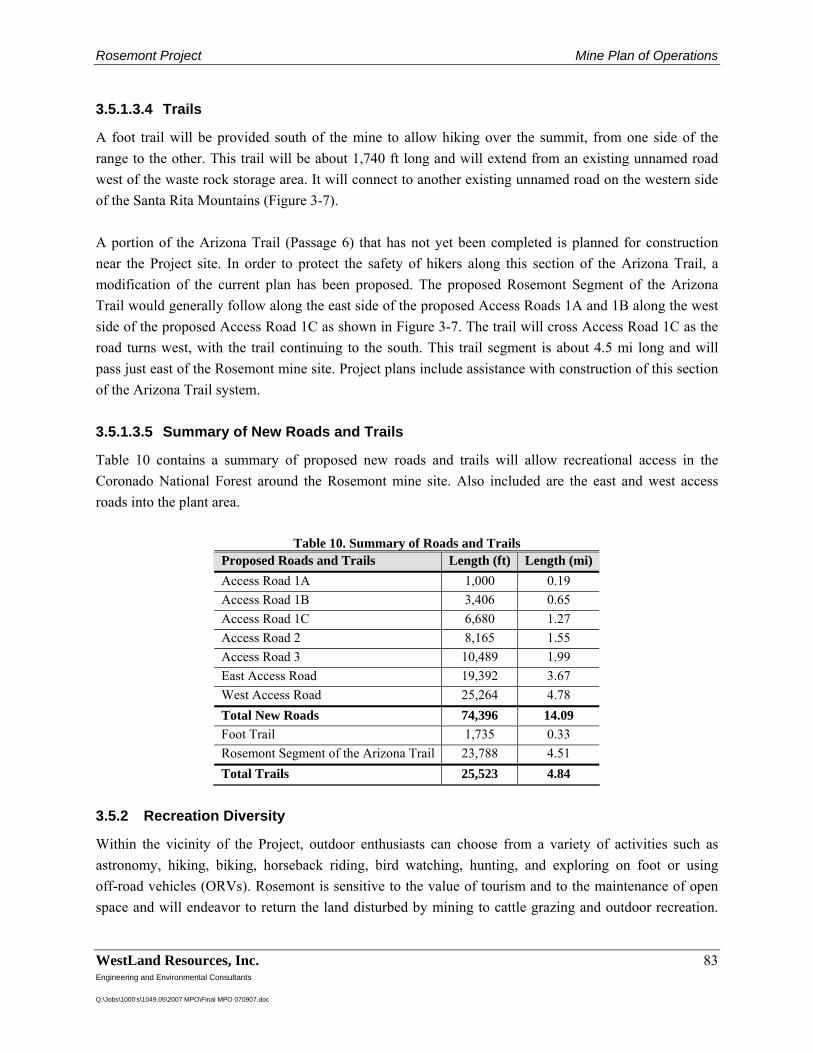
Rosemont Project Mine Plan of Operations
WestLand Resources, Inc. 83 Engineering and Environmental Consultants Q:\Jobs\1000's\1049.05\2007 MPO\Final MPO 070907.doc
3.5.1.3.4 Trails
A foot trail will be provided south of the mine to allow hiking over the summit, from one side of the range to the other. This trail will be about 1,740 ft long and will extend from an existing unnamed road west of the waste rock storage area. It will connect to another existing unnamed road on the western side of the Santa Rita Mountains (Figure 3-7). A portion of the Arizona Trail (Passage 6) that has not yet been completed is planned for construction near the Project site. In order to protect the safety of hikers along this section of the Arizona Trail, a modification of the current plan has been proposed. The proposed Rosemont Segment of the Arizona Trail would generally follow along the east side of the proposed Access Roads 1A and 1B along the west side of the proposed Access Road 1C as shown in Figure 3-7. The trail will cross Access Road 1C as the road turns west, with the trail continuing to the south. This trail segment is about 4.5 mi long and will pass just east of the Rosemont mine site. Project plans include assistance with construction of this section of the Arizona Trail system. 3.5.1.3.5 Summary of New Roads and Trails
Table 10 contains a summary of proposed new roads and trails will allow recreational access in the Coronado National Forest around the Rosemont mine site. Also included are the east and west access roads into the plant area.
Table 10. Summary of Roads and Trails Proposed Roads and Trails Length (ft) Length (mi) Access Road 1A 1,000 0.19 Access Road 1B 3,406 0.65 Access Road 1C 6,680 1.27 Access Road 2 8,165 1.55 Access Road 3 10,489 1.99 East Access Road 19,392 3.67 West Access Road 25,264 4.78 Total New Roads 74,396 14.09 Foot Trail 1,735 0.33 Rosemont Segment of the Arizona Trail 23,788 4.51 Total Trails 25,523 4.84
3.5.2 Recreation Diversity
Within the vicinity of the Project, outdoor enthusiasts can choose from a variety of activities such as astronomy, hiking, biking, horseback riding, bird watching, hunting, and exploring on foot or using off-road vehicles (ORVs). Rosemont is sensitive to the value of tourism and to the maintenance of open space and will endeavor to return the land disturbed by mining to cattle grazing and outdoor recreation.
Rosemont Project Mine Plan of Operations
WestLand Resources, Inc. 84 Engineering and Environmental Consultants Q:\Jobs\1000's\1049.05\2007 MPO\Final MPO 070907.doc
This Access Plan also provides several concepts designed to allow as much recreational use as practicable, including maintenance of public access in all areas except the Barrel Canyon drainage. 3.5.2.1 Existing Regional Recreational Opportunities
3.5.2.1.1 Hiking/Bird watching/Rock Hounding/Mountain Biking
The Santa Rita Mountains are well known to many hikers, bird watchers, mountain bikers, and other outdoor enthusiasts. Groups such as the Green Valley Recreation Hiking Club (GVRHC) often visit the Santa Rita Mountains and take advantage of various access roads and pathways, as well as off-trail hiking through less accessible areas (GVRHC 2007). During a site visit on January 24, 2007, several hikers were noted. A group of hikers were seen at Gunsight Pass and another couple, who indicated that they were scouting the trail for GVRHC, were hiking along FR 4051 to the west of the proposed mine site (Figure 3-7). A portion of the Arizona Trail, the most extensive trail in the state lies near the southern boundary of the Project and is proposed to extend north through the Project. The Arizona Trail Passages 5 and 6 provide a route for hikers and mountain bikers through the Santa Rita Mountains and Las Cienegas, which are adjacent to the Project area (Figure 3-7). The 17.2 mi segment of the Arizona Trail known as Passage 5 starts at the Gardner Trailhead, which is 5.5 mi west of State Route 83 off Gardner Canyon Road, and approximately 6 mi south of the Project. It runs to Oak Tree Canyon at FR 4072 at SR 83, at the southeast corner of the Project. The official route for Passage 6 has not yet been established, but a proposed route travels north from Oak Tree Canyon, roughly following the west side of SR 83. It crosses I-10 at Sahuarita Road and travels alongside Davidson Canyon ending 0.25 mi west of the Davidson Canyon Bridge at I-10 (approximately 9 mi northeast of the Project). Parking areas are located at the beginning and ending access points of each passage, with the exception of the ending access point for the proposed Passage 6, which is not accessible by vehicle (Jones 2005). Hikers currently utilize both Passage 5 and the proposed Passage 6 while awaiting the official construction of the latter. Mountain bikers can take advantage of moderate single-track riding through Passage 5, but are encouraged to travel along SR 83 and I-10 to reach Davidson Canyon until the construction of Passage 6 has been completed (Jones 2005). In addition to the Arizona Trail, mountain bikers have several unimproved (dirt) roads and trails to choose from in the Santa Rita Mountains. The Southern Arizona Mountain Biking Association (SAMBA) makes use of several trails in the Gardner Canyon area, some of which stretch into the southern part of the Project area (SAMBA 2002) (Figure 3-8). The Mount Wrightson Wilderness area, located approximately 4 mi southwest of the Project area, encompasses over 25,000 ac of terrain (Figure 3-8). This wilderness area is home to a variety of trails that support hiking and bird watching. No motorized or mechanized vehicles or equipment are allowed, which
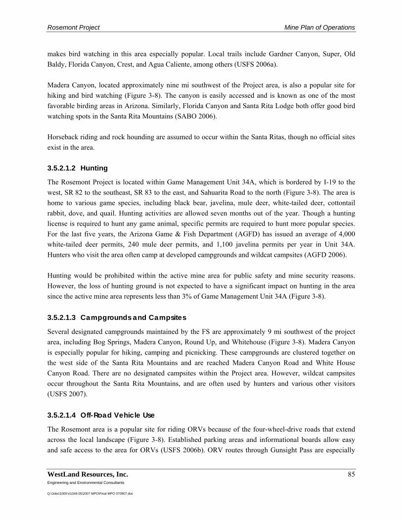
Rosemont Project Mine Plan of Operations
WestLand Resources, Inc. 85 Engineering and Environmental Consultants Q:\Jobs\1000's\1049.05\2007 MPO\Final MPO 070907.doc
makes bird watching in this area especially popular. Local trails include Gardner Canyon, Super, Old Baldy, Florida Canyon, Crest, and Agua Caliente, among others (USFS 2006a). Madera Canyon, located approximately nine mi southwest of the Project area, is also a popular site for hiking and bird watching (Figure 3-8). The canyon is easily accessed and is known as one of the most favorable birding areas in Arizona. Similarly, Florida Canyon and Santa Rita Lodge both offer good bird watching spots in the Santa Rita Mountains (SABO 2006). Horseback riding and rock hounding are assumed to occur within the Santa Ritas, though no official sites exist in the area. 3.5.2.1.2 Hunting
The Rosemont Project is located within Game Management Unit 34A, which is bordered by I-19 to the west, SR 82 to the southeast, SR 83 to the east, and Sahuarita Road to the north (Figure 3-8). The area is home to various game species, including black bear, javelina, mule deer, white-tailed deer, cottontail rabbit, dove, and quail. Hunting activities are allowed seven months out of the year. Though a hunting license is required to hunt any game animal, specific permits are required to hunt more popular species. For the last five years, the Arizona Game & Fish Department (AGFD) has issued an average of 4,000 white-tailed deer permits, 240 mule deer permits, and 1,100 javelina permits per year in Unit 34A. Hunters who visit the area often camp at developed campgrounds and wildcat campsites (AGFD 2006). Hunting would be prohibited within the active mine area for public safety and mine security reasons. However, the loss of hunting ground is not expected to have a significant impact on hunting in the area since the active mine area represents less than 3% of Game Management Unit 34A (Figure 3-8).
3.5.2.1.3 Campgrounds and Campsites
Several designated campgrounds maintained by the FS are approximately 9 mi southwest of the project area, including Bog Springs, Madera Canyon, Round Up, and Whitehouse (Figure 3-8). Madera Canyon is especially popular for hiking, camping and picnicking. These campgrounds are clustered together on the west side of the Santa Rita Mountains and are reached Madera Canyon Road and White House Canyon Road. There are no designated campsites within the Project area. However, wildcat campsites occur throughout the Santa Rita Mountains, and are often used by hunters and various other visitors (USFS 2007). 3.5.2.1.4 Off-Road Vehicle Use
The Rosemont area is a popular site for riding ORVs because of the four-wheel-drive roads that extend across the local landscape (Figure 3-8). Established parking areas and informational boards allow easy and safe access to the area for ORVs (USFS 2006b). ORV routes through Gunsight Pass are especially
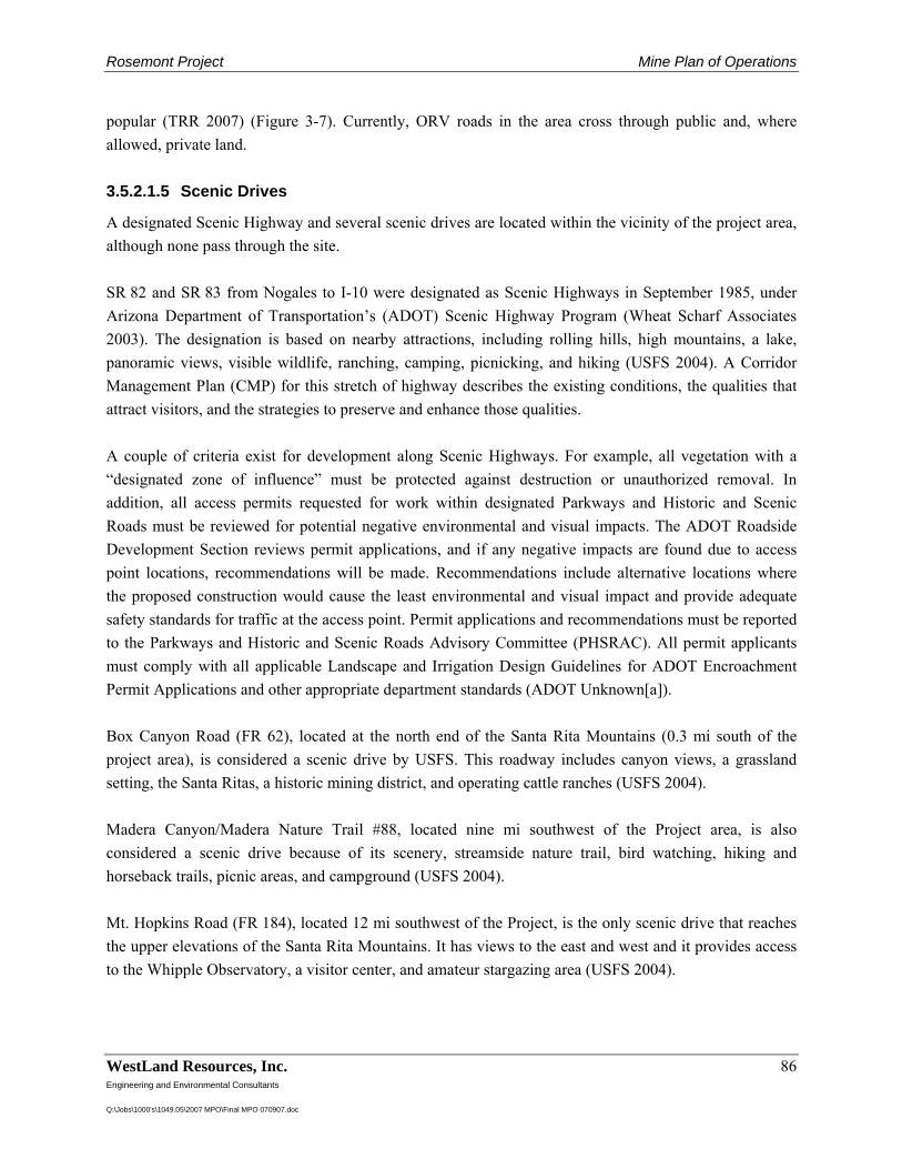
Rosemont Project Mine Plan of Operations
WestLand Resources, Inc. 86 Engineering and Environmental Consultants Q:\Jobs\1000's\1049.05\2007 MPO\Final MPO 070907.doc
popular (TRR 2007) (Figure 3-7). Currently, ORV roads in the area cross through public and, where allowed, private land.
3.5.2.1.5 Scenic Drives
A designated Scenic Highway and several scenic drives are located within the vicinity of the project area, although none pass through the site. SR 82 and SR 83 from Nogales to I-10 were designated as Scenic Highways in September 1985, under Arizona Department of Transportation’s (ADOT) Scenic Highway Program (Wheat Scharf Associates 2003). The designation is based on nearby attractions, including rolling hills, high mountains, a lake, panoramic views, visible wildlife, ranching, camping, picnicking, and hiking (USFS 2004). A Corridor Management Plan (CMP) for this stretch of highway describes the existing conditions, the qualities that attract visitors, and the strategies to preserve and enhance those qualities. A couple of criteria exist for development along Scenic Highways. For example, all vegetation with a “designated zone of influence” must be protected against destruction or unauthorized removal. In addition, all access permits requested for work within designated Parkways and Historic and Scenic Roads must be reviewed for potential negative environmental and visual impacts. The ADOT Roadside Development Section reviews permit applications, and if any negative impacts are found due to access point locations, recommendations will be made. Recommendations include alternative locations where the proposed construction would cause the least environmental and visual impact and provide adequate safety standards for traffic at the access point. Permit applications and recommendations must be reported to the Parkways and Historic and Scenic Roads Advisory Committee (PHSRAC). All permit applicants must comply with all applicable Landscape and Irrigation Design Guidelines for ADOT Encroachment Permit Applications and other appropriate department standards (ADOT Unknown[a]). Box Canyon Road (FR 62), located at the north end of the Santa Rita Mountains (0.3 mi south of the project area), is considered a scenic drive by USFS. This roadway includes canyon views, a grassland setting, the Santa Ritas, a historic mining district, and operating cattle ranches (USFS 2004). Madera Canyon/Madera Nature Trail #88, located nine mi southwest of the Project area, is also considered a scenic drive because of its scenery, streamside nature trail, bird watching, hiking and horseback trails, picnic areas, and campground (USFS 2004). Mt. Hopkins Road (FR 184), located 12 mi southwest of the Project, is the only scenic drive that reaches the upper elevations of the Santa Rita Mountains. It has views to the east and west and it provides access to the Whipple Observatory, a visitor center, and amateur stargazing area (USFS 2004).
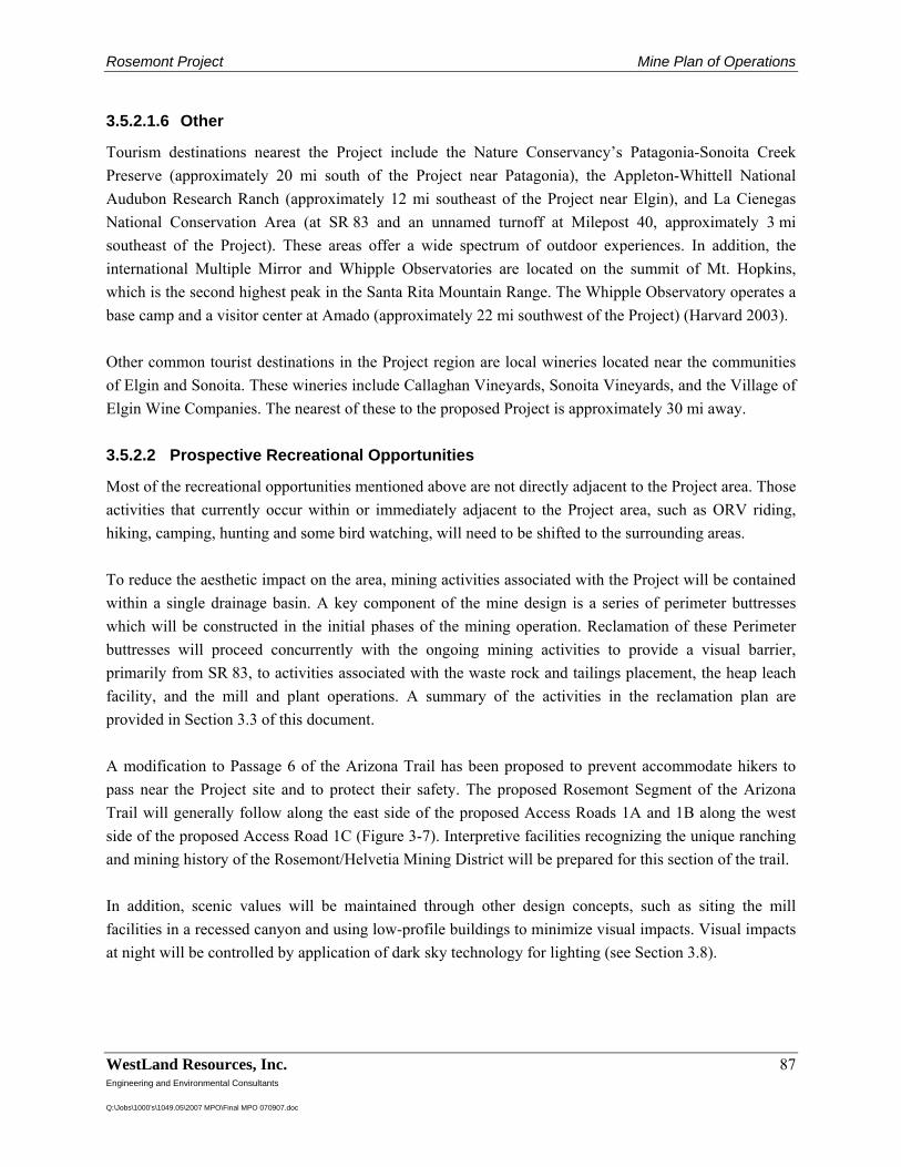
Rosemont Project Mine Plan of Operations
WestLand Resources, Inc. 87 Engineering and Environmental Consultants Q:\Jobs\1000's\1049.05\2007 MPO\Final MPO 070907.doc
3.5.2.1.6 Other
Tourism destinations nearest the Project include the Nature Conservancy’s Patagonia-Sonoita Creek Preserve (approximately 20 mi south of the Project near Patagonia), the Appleton-Whittell National Audubon Research Ranch (approximately 12 mi southeast of the Project near Elgin), and La Cienegas National Conservation Area (at SR 83 and an unnamed turnoff at Milepost 40, approximately 3 mi southeast of the Project). These areas offer a wide spectrum of outdoor experiences. In addition, the international Multiple Mirror and Whipple Observatories are located on the summit of Mt. Hopkins, which is the second highest peak in the Santa Rita Mountain Range. The Whipple Observatory operates a base camp and a visitor center at Amado (approximately 22 mi southwest of the Project) (Harvard 2003). Other common tourist destinations in the Project region are local wineries located near the communities of Elgin and Sonoita. These wineries include Callaghan Vineyards, Sonoita Vineyards, and the Village of Elgin Wine Companies. The nearest of these to the proposed Project is approximately 30 mi away.
3.5.2.2 Prospective Recreational Opportunities
Most of the recreational opportunities mentioned above are not directly adjacent to the Project area. Those activities that currently occur within or immediately adjacent to the Project area, such as ORV riding, hiking, camping, hunting and some bird watching, will need to be shifted to the surrounding areas. To reduce the aesthetic impact on the area, mining activities associated with the Project will be contained within a single drainage basin. A key component of the mine design is a series of perimeter buttresses which will be constructed in the initial phases of the mining operation. Reclamation of these Perimeter buttresses will proceed concurrently with the ongoing mining activities to provide a visual barrier, primarily from SR 83, to activities associated with the waste rock and tailings placement, the heap leach facility, and the mill and plant operations. A summary of the activities in the reclamation plan are provided in Section 3.3 of this document. A modification to Passage 6 of the Arizona Trail has been proposed to prevent accommodate hikers to pass near the Project site and to protect their safety. The proposed Rosemont Segment of the Arizona Trail will generally follow along the east side of the proposed Access Roads 1A and 1B along the west side of the proposed Access Road 1C (Figure 3-7). Interpretive facilities recognizing the unique ranching and mining history of the Rosemont/Helvetia Mining District will be prepared for this section of the trail. In addition, scenic values will be maintained through other design concepts, such as siting the mill facilities in a recessed canyon and using low-profile buildings to minimize visual impacts. Visual impacts at night will be controlled by application of dark sky technology for lighting (see Section 3.8).
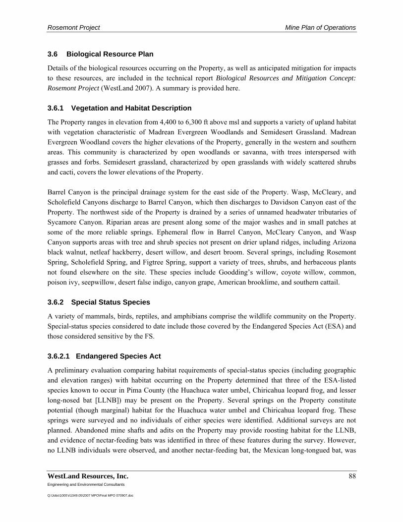
Rosemont Project Mine Plan of Operations
WestLand Resources, Inc. 88 Engineering and Environmental Consultants Q:\Jobs\1000's\1049.05\2007 MPO\Final MPO 070907.doc
3.6 Biological Resource Plan
Details of the biological resources occurring on the Property, as well as anticipated mitigation for impacts to these resources, are included in the technical report Biological Resources and Mitigation Concept: Rosemont Project (WestLand 2007). A summary is provided here. 3.6.1 Vegetation and Habitat Description
The Property ranges in elevation from 4,400 to 6,300 ft above msl and supports a variety of upland habitat with vegetation characteristic of Madrean Evergreen Woodlands and Semidesert Grassland. Madrean Evergreen Woodland covers the higher elevations of the Property, generally in the western and southern areas. This community is characterized by open woodlands or savanna, with trees interspersed with grasses and forbs. Semidesert grassland, characterized by open grasslands with widely scattered shrubs and cacti, covers the lower elevations of the Property. Barrel Canyon is the principal drainage system for the east side of the Property. Wasp, McCleary, and Scholefield Canyons discharge to Barrel Canyon, which then discharges to Davidson Canyon east of the Property. The northwest side of the Property is drained by a series of unnamed headwater tributaries of Sycamore Canyon. Riparian areas are present along some of the major washes and in small patches at some of the more reliable springs. Ephemeral flow in Barrel Canyon, McCleary Canyon, and Wasp Canyon supports areas with tree and shrub species not present on drier upland ridges, including Arizona black walnut, netleaf hackberry, desert willow, and desert broom. Several springs, including Rosemont Spring, Scholefield Spring, and Figtree Spring, support a variety of trees, shrubs, and herbaceous plants not found elsewhere on the site. These species include Goodding’s willow, coyote willow, common, poison ivy, seepwillow, desert false indigo, canyon grape, American brooklime, and southern cattail. 3.6.2 Special Status Species
A variety of mammals, birds, reptiles, and amphibians comprise the wildlife community on the Property. Special-status species considered to date include those covered by the Endangered Species Act (ESA) and those considered sensitive by the FS. 3.6.2.1 Endangered Species Act
A preliminary evaluation comparing habitat requirements of special-status species (including geographic and elevation ranges) with habitat occurring on the Property determined that three of the ESA-listed species known to occur in Pima County (the Huachuca water umbel, Chiricahua leopard frog, and lesser long-nosed bat [LLNB]) may be present on the Property. Several springs on the Property constitute potential (though marginal) habitat for the Huachuca water umbel and Chiricahua leopard frog. These springs were surveyed and no individuals of either species were identified. Additional surveys are not planned. Abandoned mine shafts and adits on the Property may provide roosting habitat for the LLNB, and evidence of nectar-feeding bats was identified in three of these features during the survey. However, no LLNB individuals were observed, and another nectar-feeding bat, the Mexican long-tongued bat, was
Rosemont Project Mine Plan of Operations
WestLand Resources, Inc. 89 Engineering and Environmental Consultants Q:\Jobs\1000's\1049.05\2007 MPO\Final MPO 070907.doc
positively identified during surveys. A biological assessment will be completed for the project to support the FS NEPA process, and results of consultation with the US Fish and Wildlife Service will be incorporated into the Project plan. 3.6.2.2 Forest Sensitive Species
Forty-seven plant species in Pima County are listed as sensitive by the FS. These species have no specific protection under the ESA, but because much of this site is on CNF, the FS takes special interest in their possible presence on the site. One of these sensitive species, the Arizona giant sedge (Carex ultra), was observed in a dense stand with some cattails (Typha domingensis) at Scholefield Spring. This sedge is rare, with its distribution generally limited to one location in each of several mountain ranges in southern Arizona. Three other sensitive plant species have not been confirmed in the Property but their presence is considered probable because of suitable habitat and known occurrence very close to the site (ARPC 2001). These species are the Bartram stonecrop (Graptopetalum bartramii), Box Canyon muhly (Muhlenbergia dubioides), and weeping muhly (Muhlenbergia xerophila). Thirty-two animal species in Pima County are listed as sensitive by the FS. As with the sensitive plants described above, these species have no legal status, but the FS takes special interest in their possible presence on the site. Three of these species—the Chiricachua leopard frog, yellow-billed cuckoo, and lesser long-nosed bat—are also ESA-listed and have been discussed above. Six other FS-listed sensitive species are considered possibly or probably present on the site, based on geographic range and habitat requirements. This group of species includes three insects, one amphibian, one reptile, and one bird. Three sensitive butterfly species are potentially present on site: the Arizona giant skipper (Agathymus aryxna), Poling’s giant skipper (Agathymus polingi), and Arizona metalmark (Calephelis rawsoni arizonensis). The Western barking frog (Eleutherodactylus augusti cactorum) is often found in caves, crevices, and abandoned mines in limestone, and it is known to be present in the Santa Rita Mountains. The canyon spotted whiptail (Aspidoscelis burti) is found in valley bottoms and riparian corridors in semidesert grassland and Madrean evergreen woodland—habitats well represented on this site (Brennan and Holycross 2006). The American peregrine falcon (Falco peregrinus anatum) is found in a wide variety of habitats, especially those with high topographic relief and available prey. Cliffs on the western edge of the Property could provide possible nest sites. Additional biological investigations will be carried out during the NEPA process, as necessary.
3.6.3 Noxious Weeds
As necessary, Rosemont Copper will initiate and maintain a program to control noxious weeds occurring within the boundary of the Project. Reseeding activity will use exclusively certified seed, weed-free straw, and any equipment from outside the United States will be cleaned prior to use.
Rosemont Project Mine Plan of Operations
WestLand Resources, Inc. 90 Engineering and Environmental Consultants Q:\Jobs\1000's\1049.05\2007 MPO\Final MPO 070907.doc
CNF approval will be obtained prior to initiating any weed control program on federal land. Weed control will be limited to chemicals and procedures approved by the CNF. The purpose of the program will be to control the growth and dissemination of noxious weeds on disturbed sites and soil stockpiles. A written annual report summarizing the noxious weed control program for the previous year will be submitted to the FS. 3.6.4 Pima County Conservation Lands System
The entire Property is included within the Pima County Conservation Land System (CLS). The CLS was adopted in 2001 by the Pima County Board of Supervisors as part of its Comprehensive Plan. These designations are used by Pima County to guide development and growth and to foster the conservation objectives of the Sonoran Desert Conservation Plan (SDCP). The development of the Project is not a discretionary action subject to Pima County’s jurisdiction, therefore, these designations have no regulatory or other implication in regard to the development of the Project. However, WestLand (2007) considers Project impacts to CLS lands and provides a mitigation strategy for these impacts.
Rosemont Project Mine Plan of Operations
WestLand Resources, Inc. 91 Engineering and Environmental Consultants Q:\Jobs\1000's\1049.05\2007 MPO\Final MPO 070907.doc
3.7 Cultural Resource Plan
The Rosemont Project area has a ranching and mining past, and many relics of these enterprises remain. In addition, evidence from past archaeological surveys indicates that prehistoric sites are present as well. A preliminary records search has shown that as many as 50 archeological surveys have been conducted on or near the Project area. As a part of the NEPA analysis, CNF, with the help of a qualified archaeological contractor, will determine the adequacy and coverage of previous archaeological work as it relates to the proposed new mine plan. A new Class III (100%) cultural resources survey will be conducted on any lands that are within the Project analysis area where previous survey coverage is determined to be inadequate or incomplete. CNF has the responsibility of consulting with interested tribal entities and the State Historic Preservation Office (SHPO) as part of the NEPA review, as well as for compliance with the National Historic Preservation Act (NHPA) Section 106. During these consultations, SHPO and interested tribes will participate in the preparation of a plan for the treatment of the cultural resources which may be affected by the Project. Rosemont project personnel will participate in this effort as directed by CNF. Rosemont Project planning has included efforts to reduce the overall footprint of the project to the minimum possible area, thereby avoiding cultural resources to the extent practicable.
Rosemont Project Mine Plan of Operations
WestLand Resources, Inc. 92 Engineering and Environmental Consultants Q:\Jobs\1000's\1049.05\2007 MPO\Final MPO 070907.doc
3.8 Lighting Plan
The Project is located in Pima County where certain types of activities fall under building, construction and operations requirements. On August 21, 2000, Pima County, along with the Town of Marana and the City of Tucson, adopted Final Ordinance No. 2001-138: The Outdoor Lighting Code (OLC). The purpose and intent of the OLC is to preserve the unique desert environment and night sky by controlling the obtrusive aspects of excessive and careless outdoor lighting usage. All outdoor lighting and associated illuminating devices must be specified and installed in conformance with the provisions of the OLC of the authorizing jurisdiction as applicable and under the appropriate permit and inspection. The OLC consists of a set of restrictions on the amount of outdoor artificial lighting allowed per unit area for various public and private property activities according to the use of the lighting; the type of lighting appliance; and the geographic location within Pima County. Specifically, the Rosemont Project is located in the two most restrictive lighting areas, defined by the OLC as E1a and E1b. Areas in E1a are around astronomical observatories and include all areas within 15 mi of the summit of Kitt Peak and 12.5 mi of the summit of Mount Hopkins. They also include those areas within any national park, monument, or forest boundary. In these areas, the preservation of a naturally dark environment, both in the sky and visible landscape, is of paramount concern. Lighting Area E1b is a circular area, 25 mi in radius, the center of which is the summit of Mount Hopkins in the Santa Rita Mountain range (Figure 3-9). The OLC states, however, that if a property is located in more than one lighting area, the entire property shall be subject to the more restrictive lighting area; therefore, the entire Property falls in Lighting Area E1a. ARS 11-830 exempts mining operations of more than five ac from Pima County zoning ordinances. Therefore, compliance with the OLC is technically not required for the Project. However, Rosemont Copper has voluntarily elected to comply with the requirements of the OLC during the projected life of the Project, including the design, construction, and daily operation phases. Specific Rosemont Project outdoor lighting design requirements and basis of design will address the following technical items as prescribed by the OLC.
3.8.1 Property Site Outdoor Light Output Limits
Table 5.1, “Maximum Total Outdoor Light Output Requirements,” of the OLC identifies the maximum total outdoor light output in units of mean lumens (lm) per net acre (a lumen is a measure of luminous flux in SI Units). A net acre is the remaining ground area within a development, parcel, or subdivision after removing all segments for proposed and existing public streets. For reference, the Pima County OLC can be found in the Appendix D of this Plan. The OLC limits lm output based on whether the lighting uses full cutoff optics (FCO) and if it is produced by low pressure sodium (LPS)-type lamp sources and luminaires (light fixtures). For example, the maximum output allowed in Lighting Area E1a is 18,000 lm per acre for FCO LPS, plus FCO non-LPS.
Rosemont Project Mine Plan of Operations
WestLand Resources, Inc. 93 Engineering and Environmental Consultants Q:\Jobs\1000's\1049.05\2007 MPO\Final MPO 070907.doc
There is also a limit of 3,000 lm per acre for FCO non-LPS. Unshielded lighting using any lamp type is prohibited. The OLC provides a definition for “Full Cutoff Light Fixture:”
A luminaire where no candela (lm) occur at or above an angle of 90 degrees above the nadir (Horizontal Plane at centerline of luminaire). This applies to all lateral angles around the luminaire. Such candela information shall be as determined by a photometric test report from a nationally recognized independent testing laboratory and as certified by the manufacturer. Any structural part of the luminaire providing this cutoff angle shielding shall be permanently attached.
FCO outdoor type lighting fixtures are readily available from a number of lighting fixture manufacturers. A typical FCO LPS streetlight casts 8,000 lm. The OLC would permit about one streetlight for every 20,000 sq ft on an isolated parking lot.
3.8.2 Lamp Type and Shielding Standards
Table 5.2 of the OLC, “Lamp Type and Shielding Standards,” describes standards for lamp types depending on the use of the light. The three classes of use are:
• Class 1 for applications requiring good color rendition, such as commercial car lots, gas stations and swap meets
• Class 2 for general illumination
• Class 3 for decorative lighting This plan assumes the Rosemont operations would fall in Class 2 (General Illumination). Furthermore, Rosemont does not anticipate the need for outdoor lighting to achieve color rendition or decorative type lighting. FCO LPS is required in all E1a areas for Class 2 lighting. Lighting other than LPS is prohibited unless the output is less than 3,000 lm per luminaire. Only FCO is required in E1b areas for Class 2.
3.8.3 Miscellaneous OLC Items
Some additional requirements of the OLC are listed below:
• Mobile/portable outdoor lighting used for flood or area lighting in support of mining operations or onsite construction activities, either permanent or temporary, shall comply with the OLC.

Rosemont Project Mine Plan of Operations
WestLand Resources, Inc. 94 Engineering and Environmental Consultants Q:\Jobs\1000's\1049.05\2007 MPO\Final MPO 070907.doc
However, temporary lighting not complying with the OLC can be used for one thirty-day period within a calendar year, with one thirty-day extension.
• Mobile equipment lights that are low voltage, incandescent lamps are exempt from compliance
with the OLC. These lights include headlights found on motorized equipment, such as haul trucks, operations vehicles, and fleet and service trucks.
• The design and specification of mercury vapor lamps and associated lighting fixtures are
prohibited and shall not be considered. Rosemont Copper operations will require adequate levels of outdoor illumination for its 24/7 operations. 3.8.4 Proposed Rosemont Mine Outdoor Lighting Design Specification
The Project, although not required to do so, will make every attempt to comply with the OLC. It should be noted, however, that federal and state laws also require Rosemont operations to give utmost attention to the safety of its employees and the public. The outdoor artificial area lighting foot-candle (fc) design will provide a maximum of 1.0 fc at all mine process and support areas and facilities. (A ft-candle is a unit of luminance in English Units, and is equal to 1.0 lm per sq ft.) The design goal is to achieve a balance between compliance with the OLC and support for safe mine operations during the course of the 24-hour per day operating schedule. Based on the category “Commercial and Industrial, Option 1” and the location in Lighting Area E 1a, a maximum total outdoor light requirement to be applied to the entire Rosemont Property (in mean lm per net ac) can be determined. This target number is 18,000 lm per ac from both FCO LPS plus FCO non-LPS. Of the 18,000 lm per ac, only 3,000 lm per ac can be from FCO non-LPS lamp sources and light fixtures.
The Rosemont outdoor lighting design will be based on using, to the greatest extent possible, full cutoff, low pressure, sodium type lamp sources and light fixtures. The goal is to provide 18,000 lm per acre while providing a safe, adequately lit work environment.
Rosemont Project Mine Plan of Operations
WestLand Resources, Inc. 95 Engineering and Environmental Consultants Q:\Jobs\1000's\1049.05\2007 MPO\Final MPO 070907.doc
References
Anderson, S. R.. 1987. “Potential for Aquifer Compaction, Land Subsidence, and Earth Fissures in the Tucson Basin, Pima County, Arizona.” U.S. Geological Survey Open-File Report: 86-482.
Anzalone, S.A. 1995. “The Helvetia Area Porphyry Systems, Pima County, Arizona: Porphyry Copper
Deposits of the American Cordillera,” Arizona Geological Society Digest, 20. Arizona Game and Fish Department (AGFD). 2006. Game Management Unit 34A.
http://www.azgfd.gov/h_f/hunting_units_34a.shtml, accessed February 1, 2007. Arizona Rare Plant Committee (ARPC). 2001. Arizona Rare Plant Field Guide. Brennan, T. C. and A. T. Holycross. 2006. A Field Guide to Amphibians and Reptiles in Arizona. Arizona
Game and Fish Department: 150. Brown, D. E. (ed.). 1982. “Biotic Communities of the American Southwest–United States and Mexico.”
Desert Plants (4): 1-4. Boyce-Thompson Arboretum, University of Arizona. Daffron, W. et.al. 2007. Geologic Report, Relogging Program at the Rosemont Porphyry Skarn Copper
Deposit. Augusta Resource Corporation internal company report, dated March 2007. Davidson, E.S. 1973. “Geohydrology and Water Resources of the Tucson Basin, Arizona.” U.S.
Geological Survey Water Supply 1939-E, with City of Tucson, U.S. Bureau of Reclamation, and the University of Arizona.
Green Valley Recreation Hiking Club (GVRHC). 2007. “Hiking Schedules, February.”
http://www.gvrhc.org/BulletinPages/February07.html, accessed February 2, 2007. Hargis and Montgomery. 1982. “Summary of Hydrologic Monitoring Program, Empire Ranch and
Rosemont areas, Arizona.” Prepared for Anamax Mining Company, May 12, 1982. Harshbarger, J.W., and Hargis, D.R. 1976. Hydrology of the Rosemont Area, Pima County, Arizona.
Preliminary Draft of Part 1. Prepared for Anamax Mining Company, October 15, 1976. Harshbarger and Associates, Inc. 1980. “Summary of Hydrologic Monitoring program, Empire Ranch and
Rosemont areas, Arizona.” Annual report, AR-192/194-80-1. Prepared for Anamax Mining Company, March 18, 1980.
Harshbarger and Associates, Inc. 1981. “Summary of Hydrologic Monitoring Program, Empire Ranch
and Rosemont areas, Arizona.” Annual report, AR-192/194-81-1. Prepared for Anamax Mining Company, February 3, 1981.
Rosemont Project Mine Plan of Operations
WestLand Resources, Inc. 96 Engineering and Environmental Consultants Q:\Jobs\1000's\1049.05\2007 MPO\Final MPO 070907.doc
Harvard. 2003. MMT Observatory Public Information, About the MMT. http://cfa-www.harvard.edu/mmt/aboutmmt.html, accessed February 8, 2007.
Jones, Tom Lorang, Rebecca Finkel, and Jerry Sieve. 2005. Arizona Trail, the Official Guide. The
Arizona Trail Association. Westcliffe Publishers, Inc., Englewood, CO. Montgomery and Associates. 2007. “Results of Construction, Development, and Testing for Exploration
Water Well (D-17-14)17bdd[E-1].” Technical Report, April 27, 2007. Murphy, B.A. and J.D Hedley. 1984. Maps Showing Groundwater Conditions in the Upper Santa Cruz
Basin Area, Pima, Santa Cruz, Pinal and Cochise Counties, Arizona, 1982. Department of Water Resources, Hydrologic Map Series Report. Number 11, January 1984.
Pima Association of Governments. 1979. Upper Santa Cruz Groundwater Quality Baseline Report,
December 1979. _____. 1983a, Assessment of Nitrate in Groundwater of the Upper Santa Cruz Basin, September 1983. _____. 1983b, Groundwater Monitoring in the Tucson Copper Mining District, September 1983. _____. 1983c, Regionwide Groundwater Quality in the Upper Santa Cruz Basin. Mines Task Force Area,
September 1983. Southeastern Arizona Bird Observatory (SABO). 2006. “Guide to Birding Hotspots: The Santa Rita
Mountains & Santa Cruz County.” http://www.sabo.org/birding/santa.htm, accessed February 7, 2007.
Southern Arizona Mountain Biking Association (SAMBA). 2002. Gardner Canyon Area Map.
http://sambabike.org/ftp/samba/MAPS/Gardner%20Canyon%20Area.pdf, accessed March 6, 2007.
Tetra Tech. 2007a. “Baseline Geochemical Characterization.” Prepared for Augusta Resource
Corporation, June 2007. _____. 2007b. “Dry Tailings Facility Design Report.” Prepared for Augusta Resource Corporation, June
2007. _____. 2007c. Geologic Hazards Assessment. Prepared for Augusta Resource Corporation, June 2007. _____. 2007d. Geotechnical Study Report. Prepared for Augusta Resource Corporation, June 2007. _____. 2007e. Groundwater Protection Plan. Prepared for Augusta Resource Corporation, June 2007.
Rosemont Project Mine Plan of Operations
WestLand Resources, Inc. 97 Engineering and Environmental Consultants Q:\Jobs\1000's\1049.05\2007 MPO\Final MPO 070907.doc
_____. 2007f. “Leaching Facility Design Report.” Prepared for Augusta Resource Corporation, June
2007. _____. 2007g. “Site Water Management Plan.” Prepared for Augusta Resource Corporation, June 2007. _____. 2007h. Viewshed Analysis. Technical Memorandum prepared for Augusta Resource Corporation,
dated June 29, 2007. _____. 2007i. “Waste Management Plan.” Prepared for Augusta Resource Corporation, June 2007. Tucson Rough Riders, Inc (TRR). 2007. “Club Activities and Events.”
http://www.tucsonroughriders.com/activities.htm, accessed February 7, 2007. United States Forest Service (FS). 2007. “Coronado National Forest, Camping and Picnicking Recreation
Sites.” http://www.fs.fed.us/r3/coronado/forest/recreation/camping/camp_pic_list.shtml, accessed February 1, 2007.
______. 2006a. Coronado National Forest, Mt. Wrightson Wilderness.
http://www.fs.fed.us/r3/coronado/forest/recreation/wilderness/wrightson.shtml, accessed February 1, 2007.
______.2006b. Santa Rita Backcountry Touring Map. http://www.fs.fed.us/r3/coronado/forest/
recreation/ohv/ohv_images/santa_rita_ohv.pdf, accessed February 7, 2007. ______. 2004. Recreational Activities: Scenic Drives. http://www.fs.fed.us/r3/coronado/forest/recreation/
scenic_drives/scenic.shtml, accessed March 6, 2007. University of Arizona. 1977. “An Environmental Inventory of the Rosemont Area in Southern Arizona.”
Volume I: The Present Environment. Edited by Davis, R., and J.R Callahan. Vector Arizona. 2006. “Rosemont Tailings Siting Study.” Technical report, May 26, 2006. Wardrop. 2005. Technical Report on the Rosemont Property, Pima County, Arizona. August 16, 2005. Western Regional Climate Center. 2006. Arizona climate summaries. http://www.wrcc.dri.edu/
summary/climsmaz.html, accessed May 16, 2006. WestLand Resources, Inc. 2007. “Biological Resources and Mitigation Concept, Rosemont Project.”
Rosemont Project Mine Plan of Operations
WestLand Resources, Inc. 98 Engineering and Environmental Consultants Q:\Jobs\1000's\1049.05\2007 MPO\Final MPO 070907.doc
Wheat Scharf Associates. 2003. “Corridor Management Plan for the Patagonia-Sonoita Scenic Road.” http://www.superstitionfreeway.com/highways/SWProjMgmt/enhancement/scenic_roads/PDF/cmp_patagonia_text.pdf, accessed April 5, 2007.