Embed Size (px)
Citation preview
Advances in Robotics Research, Vol. 2, No. 2 (2018) 113-127
DOI: https://doi.org/10.12989/arr.2018.2.2.113 113
Copyright © 2018 Techno-Press, Ltd.
http://www.techno-press.org/?journal=arr&subpage=7 ISSN: 2287-4976 (Print), 2287-4984 (Online)
ROS-based control for a robot manipulator with a demonstration of the ball-on-plate task
Khasim A. Khana, Revanth R. Kondab and Ji-Chul Ryu*
Department of Mechanical Engineering, Northern Illinois University, DeKalb, IL 60115, U.S.A.
(Received December 5, 2017, Revised March 27, 2018, Accepted April 12, 2018)
Abstract. Robotics and automation are rapidly growing in the industries replacing human labor. The idea of
robots replacing humans is positively influencing the business thereby increasing its scope of research. This
paper discusses the development of an experimental platform controlled by a robotic arm through Robot
Operating System (ROS). ROS is an open source platform over an existing operating system providing
various types of robots with advanced capabilities from an operating system to low-level control. We aim in
this work to control a 7-DOF manipulator arm (Robai Cyton Gamma 300) equipped with an external vision
camera system through ROS and demonstrate the task of balancing a ball on a plate-type end effector. In
order to perform feedback control of the balancing task, the ball is designed to be tracked using a camera
(Sony PlayStation Eye) through a tracking algorithm written in C++ using OpenCV libraries. The joint
actuators of the robot are servo motors (Dynamixel) and these motors are directly controlled through a low-
level control algorithm. To simplify the control, the system is modeled such that the plate has two-axis
linearized motion. The developed system along with the proposed approaches could be used for more
complicated tasks requiring more number of joint control as well as for a testbed for students to learn ROS
with control theories in robotics.
Keywords: robot operating system (ROS); robot manipulator; balancing control; ball-on-plate system
1. Introduction
Robotics has been growing past the traditional engineering techniques emerging as a newer
field of modern technology that requires various knowledge from mechanical and electrical
engineering and computer science. When commercial robots are used, the manufacturers often
allow users to access the robots in the form of GUI (Graphical User Interface) or APIs
(Application Program Interfaces) are provided for further user-customized functionality.
The GUI provided by manufacturers is often not capable of fully exploiting the abilities of the
robot and dealing directly with the APIs may be unwieldly. To overcome these inadequacies,
middleware packages have been developed (Quigley et al. 2009, Bonarini et al. 2014) and one
Corresponding author, Assistant Professor, E-mail: [email protected] aGraudate Student, E-mail: [email protected]
bGraduate Student, E-mail: [email protected]
Khasim A. Khan, Revanth R. Konda and Ji-Chul Ryu
such package is Robot Operating System (ROS). ROS is an open source middleware package that
works between multiple platforms and performs OS-like functionality. Since Quigley et al. (2009)
first developed ROS with the design goals of “Peer to Peer, Multi-lingual, Tools-based, Thin, Free
and Open-sources,” it has been widely used as software framework of various types of robotic
systems. Meeussen et al. (2010) use ROS to provide distributed computation for autonomous door
opening of a mobile robot called “PR2.” For the same mobile manipulator system, Hornung et al.
(2012) develop a 3D navigation framework based on the Search-Based Planning Library (SBPL)
which is part of ROS. Allgeuer et al. (2013) implement ROS to a humanoid robot providing visual
perception, hardware abstraction, and behavior generation. Aerial robotics is also one of the
popular areas in which the software architecture is often built upon ROS. Korpela et al. (2012) use
ROS to integrate the components of their unmanned aerial vehicle named “MM-UAV.” ROS also
has a capability that enables the use of other middleware packages along with it. DeMarco et al.
(2011) integrate MOOS (Mission Oriented Operating Suite), which is popular in the underwater
robotics, with ROS to interface different subsystems that are intrinsically difficult to communicate
for their autonomous underwater vehicle. From a simple robotic platform such as an Arduino-
based mobile robot (Araujo et al. 2014) to advanced systems that require high end capabilities like
SLAM (Santos et al. 2013), ROS has been gaining growing popularity in the robotics community.
The goal of this work is to develop a ROS-based software framework for a manipulator arm
which is designed to accomplish complicated tasks. For a demonstration purpose, the task of
balancing a ball on a plate has been set on the chosen manipulator arm (Robai Cyton Gamma 300)
in this paper. A typical ball and plate system consists of a plate, which has two rotational motions
about two perpendicular axes on the plate plane, and a ball, which is placed on the plate and would
roll when the plate is tilted under the influence of gravity. This intrinsically nonlinear system has
been widely used to demonstrate various control methods. Awtar et al. (2002) apply a state-
feedback control using the pole placement method to calculate desired angular positions of the
plate in the outer loop while a PID controller in the inner loop is designed to achieve the desired
angular position. Knuplei et al. (2003) use a lead controller with a camera tracking the ball
whereas a resistive touch-sensitive glass plate is used to sense the ball position in the work of
Awtar et al. (2002). Mochizuki and Ichihara (2013) apply I-PD controller, which is a variant of a
PID controller, based on generalized Kalman-Yakubovich-Popov (KYP) lemma. Ho et al. (2013)
apply approximate input-output feedback linearization for each decoupled ball and beam system
since the system is not fully feedback linearizable. Nonlinear backstepping control is employed by
Wang et al. (2008) for the ball-on-plate system along with a switching control in the inner loop of
the control structure. Liu et al. (2010) design a nonlinear controller based on the sliding mode
control technique. Using the proposed controller, trajectory tracking capability is demonstrated in
their work. Ghiasi et al. (2012) propose a robust optimal controller based on the H-infinity
approach to solve a ball trajectory tracking problem under the presence of uncertainties and
disturbances. Different approaches to balancing the ball have also been studied such as fuzzy logic
(Fan et al. 2004), PID neural network (Zheng et al. 2011), and fuzzy neural network (Dong et al.
2011).
Since most of these previous works rely on a linearized model considering it as two
independent ball-on-beam systems while giving satisfactory control performance, the same
approach has been adopted in this work. This paper presents the development of a ROS-based
software architecture for the chosen manipulator, integrated with a linear control technique and
vision tracking system, that demonstrates a task of balancing a ball on a plate. Building on the
authors’ previous work (Khan and Ryu 2017), in this paper we present satisfactory experimental
114
ROS-based control for a robot manipulator with a demonstration of the ball-on-plate task
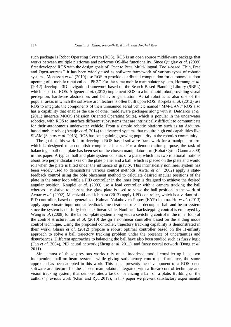
Fig. 1 Experimental setup of the system
results by properly implementing the proposed control scheme.
The rest of the paper is organized as follows: In Section 2, the overview of the developed
system is explained. In Section 3, the structure of the designed ROS-based architecture is
presented. In Section 4, the derivation of a linearized dynamic model and the design of linear
control law are provided. Simulation and experimental results are presented in Section 5, followed
by concluding remarks in Section 6.
2. System overview
The system used for the demonstration consists of a 7-DOF robotic arm (Robai Cyton Gamma
300) having 7 servo motors (Dynamixel) as joint actuators, a plate-type end effector, and a vision
camera system for tracking. Even though the manipulator has kinematic redundancy with its seven
degrees of freedom, only two axes are used as it is sufficient to control the plate for the balancing
task. The vision system uses a low-cost USB camera (Sony PlayStation Eye) with frame rates of
up to 120 Hz.
As shown in Fig. 1, the plate is held by the gripper of the arm. The plate is given two-axis
motion by using two joints of the robot, which is described in more detail in Section 4. For
material of the plate and ball, foam and soft rubber were selected respectively, based on the
payload limitations of 300 g of the robot arm. Although the model-based control algorithm is
designed to work with any mass and size of the ball in principle, a smaller ball was considered to
provide enough workspace on the plate along with the payload constraint.
3. System programming with ROS
3.1 Structure of the system software in ROS
ROS is an open-source framework and integrated development environment (IDE) for writing
robot software (Quigley et al. 2009, Martinez and Fernandez 2013). Since the software interface of
the manipulator arm provided by the manufacturer does not give the user complete control over its
functionalities, a new software architecture was developed using ROS in this work. This software
115
Khasim A. Khan, Revanth R. Konda and Ji-Chul Ryu
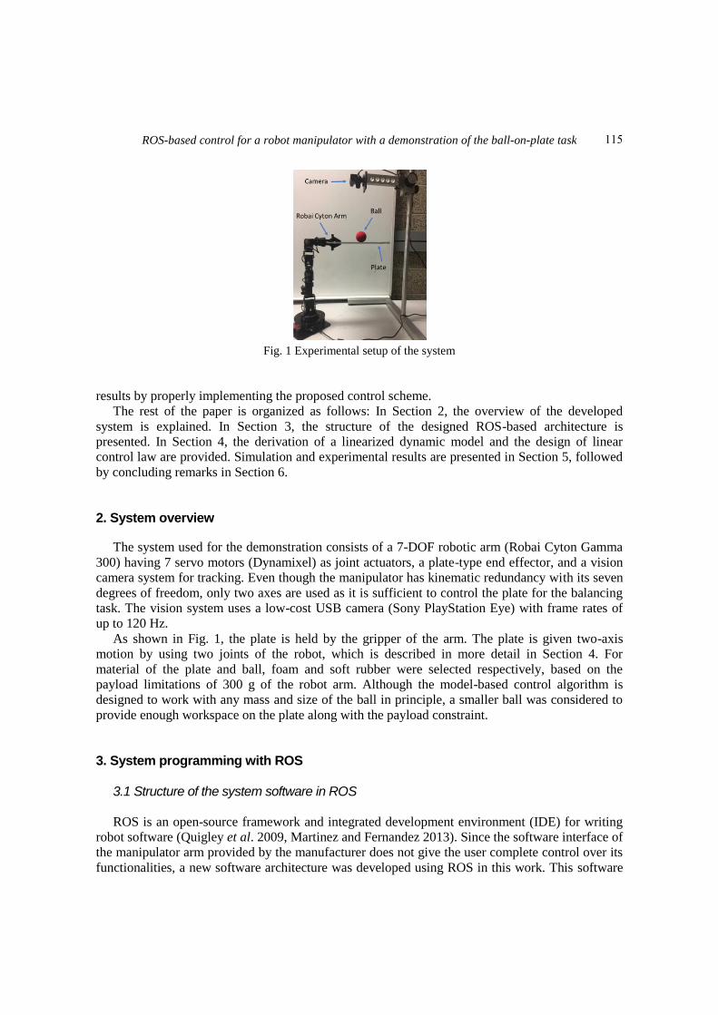
Fig. 2 Employed software architecture of the system in ROS
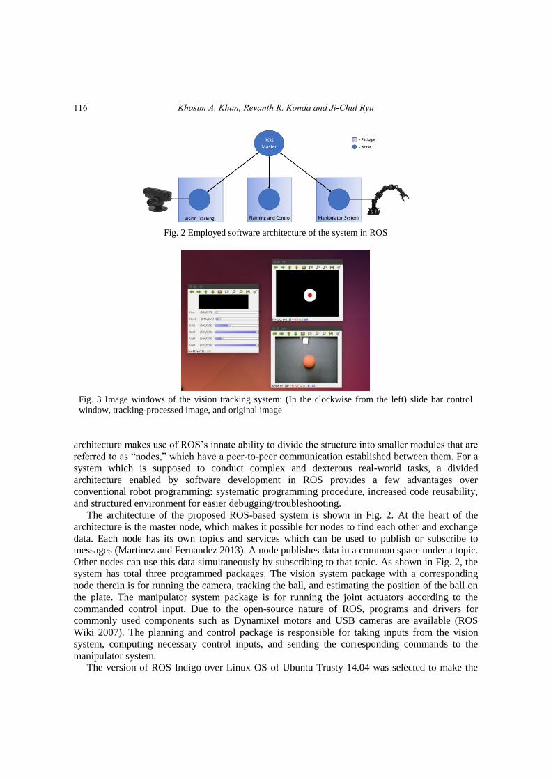
Fig. 3 Image windows of the vision tracking system: (In the clockwise from the left) slide bar control
window, tracking-processed image, and original image
architecture makes use of ROS’s innate ability to divide the structure into smaller modules that are
referred to as “nodes,” which have a peer-to-peer communication established between them. For a
system which is supposed to conduct complex and dexterous real-world tasks, a divided
architecture enabled by software development in ROS provides a few advantages over
conventional robot programming: systematic programming procedure, increased code reusability,
and structured environment for easier debugging/troubleshooting.
The architecture of the proposed ROS-based system is shown in Fig. 2. At the heart of the
architecture is the master node, which makes it possible for nodes to find each other and exchange
data. Each node has its own topics and services which can be used to publish or subscribe to
messages (Martinez and Fernandez 2013). A node publishes data in a common space under a topic.
Other nodes can use this data simultaneously by subscribing to that topic. As shown in Fig. 2, the
system has total three programmed packages. The vision system package with a corresponding
node therein is for running the camera, tracking the ball, and estimating the position of the ball on
the plate. The manipulator system package is for running the joint actuators according to the
commanded control input. Due to the open-source nature of ROS, programs and drivers for
commonly used components such as Dynamixel motors and USB cameras are available (ROS
Wiki 2007). The planning and control package is responsible for taking inputs from the vision
system, computing necessary control inputs, and sending the corresponding commands to the
manipulator system.
The version of ROS Indigo over Linux OS of Ubuntu Trusty 14.04 was selected to make the
116
ROS-based control for a robot manipulator with a demonstration of the ball-on-plate task
best use of pre-developed resources such as the packages for Dynamixel joint actuators and USB
cameras.
3.2 Vision tracking system in ROS
A low-cost Sony PlayStation Eye USB camera is mounted above the plate to track the position
of the ball as shown in Fig. 1. The object tracking to get the position of the ball is done by a series
of image processing steps on grabbed image frames such as image conversion to the HSV color
space followed by conversion to grey scale, thresholding, and filtering. OpenCV libraries are used
to accomplish the task of tracking a red-colored object (Baggio et al. 2012).
The vision tracking system working in multiple windows in Ubuntu OS is shown in Fig. 3. A
slide bar control window is created to set the values for HSV, thresholds, and filtering. The
PlayStation Eye camera can produce an image frame with a resolution of 320×240 pixels at a
frame rate of 120 Hz. Therefore, the camera is strategically mounted on the fixture above the plate
of 320×240 mm2 at a height of 332 mm so that it can cover the entire plate with a position
resolution of 1 mm.
3.3 Robai Cyton Gamma 300 with ROS
As mentioned earlier, since the manufacturer of the manipulator arm provides the user with
limited control options, the manipulator system package is programmed on top of the Dynamixel
package available online (ROS Wiki 2017) to gain complete control over the functionalities of the
robot by direct access to the Dynamixel joint actuators. In the implementation, it is important to
understand two different control modes available for Dynamixel joint actuators: ‘Joint’ (position)
mode and ‘Wheel’ (velocity) mode. Under the joint mode, the Dynamixel joint actuators run based
on position inputs with position limits set in the configuration file. On the other hand, under the
wheel mode, output velocity is the one to be controlled. In this paper, the wheel mode is selected
to be used because the calculated torque input from the control law will be subsequently converted
to corresponding velocity input for the arm control, which will be explained in more detail later.
The manipulator system package is created to establish communication from/to the joint
actuators. It consists of motor configuration file and related launch files. In this package, two joint
controllers were programmed for each of the two joint actuators used for the ball-on-plate task.
These joint controllers are for communication with the motors and are different from the controller
developed in Section 4.3 for the balancing task. Since, in the proposed demonstration task, only
two joint actuators of the 7-DOF manipulator arm need to be controlled in the velocity mode, the
other five joints are set to a fixed position as shown in Fig. 1 using the position mode. This is
accomplished by first creating a configuration file with the file name extension of ‘yaml’ in which
all the necessary parameters are set up. Then a launch file is created to load all the joint controller
parameters to the ROS master and start the controllers. A batch file created with the file name
extension of ‘sh’ manages moving initially the remaining five joint actuators to a fixed upright
position. The joint controllers were programmed so that they send velocity input commands to the
two joint actuators which are aligned with the two plate motion axes.
Another important aspect of the Dynamixel joint actuators in using them under ROS is that we
can only obtain the position data through the encoder, not the velocity. The angular velocity of the
joint actuator can be obtained by numerically differentiating the measured position data through a
(digital) low-pass filter.
117
Khasim A. Khan, Revanth R. Konda and Ji-Chul Ryu
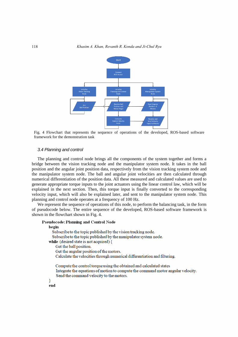
Fig. 4 Flowchart that represents the sequence of operations of the developed, ROS-based software
framework for the demonstration task
3.4 Planning and control
The planning and control node brings all the components of the system together and forms a
bridge between the vision tracking node and the manipulator system node. It takes in the ball
position and the angular joint position data, respectively from the vision tracking system node and
the manipulator system node. The ball and angular joint velocities are then calculated through
numerical differentiation of the position data. All these measured and calculated values are used to
generate appropriate torque inputs to the joint actuators using the linear control law, which will be
explained in the next section. Then, this torque input is finally converted to the corresponding
velocity input, which will also be explained later, and sent to the manipulator system node. This
planning and control node operates at a frequency of 100 Hz.
We represent the sequence of operations of this node, to perform the balancing task, in the form
of pseudocode below. The entire sequence of the developed, ROS-based software framework is
shown in the flowchart shown in Fig. 4.
118
ROS-based control for a robot manipulator with a demonstration of the ball-on-plate task
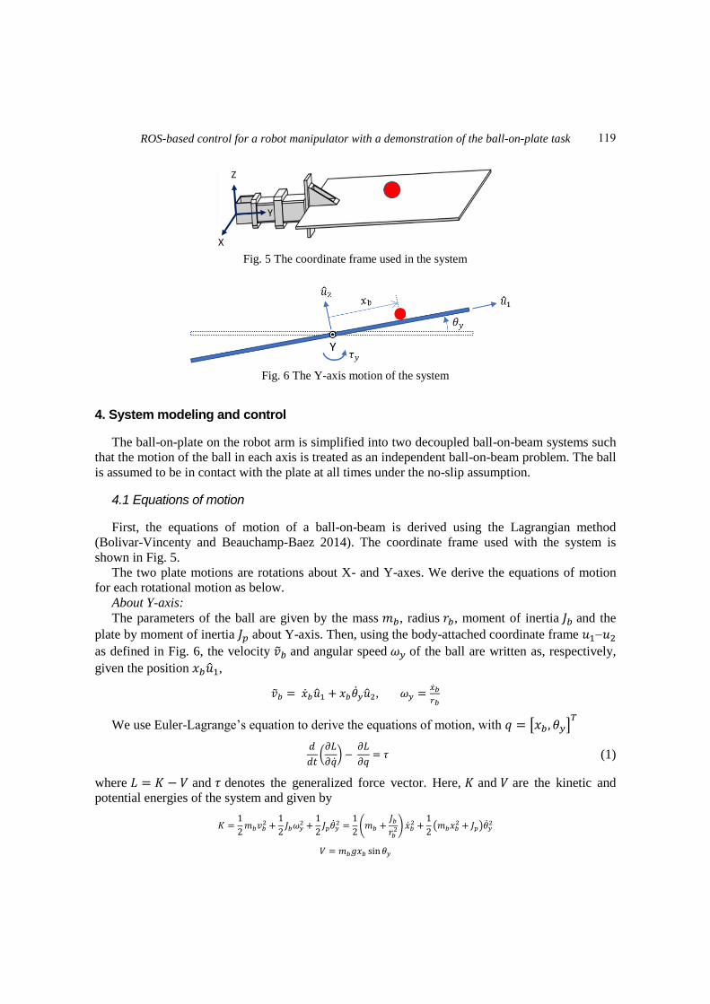
Fig. 5 The coordinate frame used in the system
Fig. 6 The Y-axis motion of the system
4. System modeling and control
The ball-on-plate on the robot arm is simplified into two decoupled ball-on-beam systems such
that the motion of the ball in each axis is treated as an independent ball-on-beam problem. The ball
is assumed to be in contact with the plate at all times under the no-slip assumption.
4.1 Equations of motion
First, the equations of motion of a ball-on-beam is derived using the Lagrangian method
(Bolivar-Vincenty and Beauchamp-Baez 2014). The coordinate frame used with the system is
shown in Fig. 5.
The two plate motions are rotations about X- and Y-axes. We derive the equations of motion
for each rotational motion as below.
About Y-axis:
The parameters of the ball are given by the mass 𝑚𝑏, radius 𝑟𝑏, moment of inertia 𝐽𝑏 and the
plate by moment of inertia 𝐽𝑝 about Y-axis. Then, using the body-attached coordinate frame 𝑢1𝑢2
as defined in Fig. 6, the velocity �̃�𝑏 and angular speed 𝜔𝑦 of the ball are written as, respectively,
given the position 𝑥𝑏�̂�1,
�̃�𝑏 = �̇�𝑏�̂�1 + 𝑥𝑏�̇�𝑦�̂�2, 𝜔𝑦 =�̇�𝑏
𝑟𝑏
We use Euler-Lagrange’s equation to derive the equations of motion, with 𝑞 = [𝑥𝑏 , 𝜃𝑦]𝑇
𝑑
𝑑𝑡(𝜕𝐿
𝜕�̇�) −
𝜕𝐿
𝜕𝑞= 𝜏 (1)
where 𝐿 = 𝐾 − 𝑉 and 𝜏 denotes the generalized force vector. Here, 𝐾 and 𝑉 are the kinetic and
potential energies of the system and given by
𝐾 =1
2𝑚𝑏𝑣𝑏
2 +1
2𝐽𝑏𝜔𝑦
2 +1
2𝐽𝑝�̇�𝑦
2 =1
2(𝑚𝑏 +
𝐽𝑏𝑟𝑏
2) �̇�𝑏2 +
1
2(𝑚𝑏𝑥𝑏
2 + 𝐽𝑝)�̇�𝑦2
𝑉 = 𝑚𝑏𝑔𝑥𝑏 sin𝜃𝑦
119
Khasim A. Khan, Revanth R. Konda and Ji-Chul Ryu
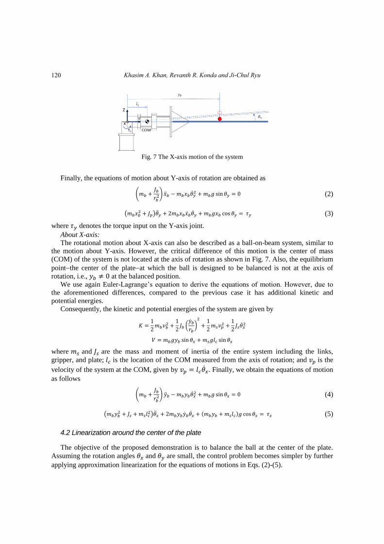
Fig. 7 The X-axis motion of the system
Finally, the equations of motion about Y-axis of rotation are obtained as
(𝑚𝑏 +𝐽𝑏
𝑟𝑏2) �̈�𝑏 − 𝑚𝑏𝑥𝑏�̇�𝑦
2 + 𝑚𝑏𝑔 sin 𝜃𝑦 = 0 (2)
(𝑚𝑏𝑥𝑏2 + 𝐽𝑝)�̈�𝑦 + 2𝑚𝑏𝑥𝑏�̇�𝑏�̇�𝑦 + 𝑚𝑏𝑔𝑥𝑏 cos 𝜃𝑦 = 𝜏𝑦 (3)
where 𝜏𝑦 denotes the torque input on the Y-axis joint.
About X-axis:
The rotational motion about X-axis can also be described as a ball-on-beam system, similar to
the motion about Y-axis. However, the critical difference of this motion is the center of mass
(COM) of the system is not located at the axis of rotation as shown in Fig. 7. Also, the equilibrium
pointthe center of the plateat which the ball is designed to be balanced is not at the axis of
rotation, i.e., 𝑦𝑏 ≠ 0 at the balanced position.
We use again Euler-Lagrange’s equation to derive the equations of motion. However, due to
the aforementioned differences, compared to the previous case it has additional kinetic and
potential energies.
Consequently, the kinetic and potential energies of the system are given by
𝐾 =1
2𝑚𝑏𝑣𝑏
2 +1
2𝐽𝑏 (
�̇�𝑏
𝑟𝑏)2
+1
2𝑚𝑠𝑣𝑝
2 +1
2𝐽𝑠�̇�𝑥
2
𝑉 = 𝑚𝑏𝑔𝑦𝑏 sin 𝜃𝑥 + 𝑚𝑠𝑔𝑙𝑐 sin 𝜃𝑥
where 𝑚𝑠 and 𝐽𝑠 are the mass and moment of inertia of the entire system including the links,
gripper, and plate; 𝑙𝑐 is the location of the COM measured from the axis of rotation; and 𝑣𝑝 is the
velocity of the system at the COM, given by 𝑣𝑝 = 𝑙𝑐�̇�𝑥. Finally, we obtain the equations of motion
as follows
(𝑚𝑏 +𝐽𝑏
𝑟𝑏2) �̈�𝑏 − 𝑚𝑏𝑦𝑏�̇�𝑥
2 + 𝑚𝑏𝑔 sin 𝜃𝑥 = 0 (4)
(𝑚𝑏𝑦𝑏2 + 𝐽𝑠 + 𝑚𝑠𝑙𝑐
2)�̈�𝑥 + 2𝑚𝑏𝑦𝑏�̇�𝑏�̇�𝑥 + (𝑚𝑏𝑦𝑏 + 𝑚𝑠𝑙𝑐)𝑔 cos 𝜃𝑥 = 𝜏𝑥 (5)
4.2 Linearization around the center of the plate
The objective of the proposed demonstration is to balance the ball at the center of the plate.
Assuming the rotation angles 𝜃𝑥 and 𝜃𝑦 are small, the control problem becomes simpler by further
applying approximation linearization for the equations of motions in Eqs. (2)-(5).
120
ROS-based control for a robot manipulator with a demonstration of the ball-on-plate task
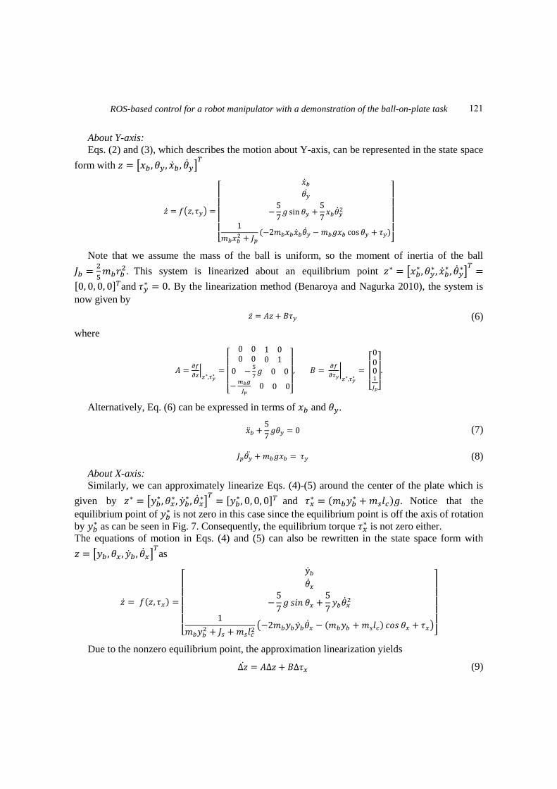
About Y-axis:
Eqs. (2) and (3), which describes the motion about Y-axis, can be represented in the state space
form with 𝑧 = [𝑥𝑏 , 𝜃𝑦, �̇�𝑏 , �̇�𝑦]𝑇
�̇� = 𝑓(𝑧, 𝜏𝑦) =
[
�̇�𝑏
𝜃�̇�
−5
7𝑔 sin 𝜃𝑦 +
5
7𝑥𝑏�̇�𝑦
2
1
𝑚𝑏𝑥𝑏2 + 𝐽𝑝
(−2𝑚𝑏𝑥𝑏�̇�𝑏�̇�𝑦 − 𝑚𝑏𝑔𝑥𝑏 cos 𝜃𝑦 + 𝜏𝑦)]
Note that we assume the mass of the ball is uniform, so the moment of inertia of the ball
𝐽𝑏 =2
5𝑚𝑏𝑟𝑏
2. This system is linearized about an equilibrium point 𝑧∗ = [𝑥𝑏∗ , 𝜃𝑦
∗, �̇�𝑏∗ , �̇�𝑦
∗]𝑇
=
[0, 0, 0, 0]𝑇and 𝜏𝑦∗ = 0. By the linearization method (Benaroya and Nagurka 2010), the system is
now given by
�̇� = 𝐴𝑧 + 𝐵𝜏𝑦 (6)
where
𝐴 =𝜕𝑓
𝜕𝑧|𝑧∗,𝜏𝑦
∗=
[
0 0 1 00 0 0 1
0 −5
7𝑔 0 0
−𝑚𝑏𝑔
𝐽𝑝0 0 0
]
, 𝐵 = 𝜕𝑓
𝜕𝜏𝑦|𝑧∗,𝜏𝑦
∗=
[ 0001
𝐽𝑝]
.
Alternatively, Eq. (6) can be expressed in terms of 𝑥𝑏 and 𝜃𝑦.
�̈�𝑏 +5
7𝑔𝜃𝑦 = 0 (7)
𝐽𝑝𝜃�̈� + 𝑚𝑏𝑔𝑥𝑏 = 𝜏𝑦 (8)
About X-axis:
Similarly, we can approximately linearize Eqs. (4)-(5) around the center of the plate which is
given by 𝑧∗ = [𝑦𝑏∗, 𝜃𝑥
∗, �̇�𝑏∗, �̇�𝑥
∗]𝑇
= [𝑦𝑏∗, 0, 0, 0]𝑇 and 𝜏𝑥
∗ = (𝑚𝑏𝑦𝑏∗ + 𝑚𝑠𝑙𝑐)𝑔. Notice that the
equilibrium point of 𝑦𝑏∗ is not zero in this case since the equilibrium point is off the axis of rotation
by 𝑦𝑏∗ as can be seen in Fig. 7. Consequently, the equilibrium torque 𝜏𝑥
∗ is not zero either.
The equations of motion in Eqs. (4) and (5) can also be rewritten in the state space form with
𝑧 = [𝑦𝑏 , 𝜃𝑥, �̇�𝑏 , �̇�𝑥]𝑇
as
�̇� = 𝑓(𝑧, 𝜏𝑥) =
[
�̇�𝑏
�̇�𝑥
−5
7𝑔 𝑠𝑖𝑛 𝜃𝑥 +
5
7𝑦𝑏�̇�𝑥
2
1
𝑚𝑏𝑦𝑏2 + 𝐽𝑠 + 𝑚𝑠𝑙𝑐
2(−2𝑚𝑏𝑦𝑏�̇�𝑏�̇�𝑥 − (𝑚𝑏𝑦𝑏 + 𝑚𝑠𝑙𝑐) 𝑐𝑜𝑠 𝜃𝑥 + 𝜏𝑥)
]
Due to the nonzero equilibrium point, the approximation linearization yields
Δ�̇� = 𝐴Δ𝑧 + 𝐵Δ𝜏𝑥 (9)
121
Khasim A. Khan, Revanth R. Konda and Ji-Chul Ryu
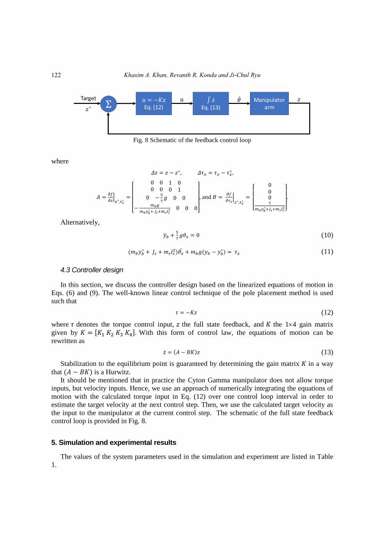
Fig. 8 Schematic of the feedback control loop
where
𝛥𝑧 = 𝑧 − 𝑧∗, 𝛥𝜏𝑥 = 𝜏𝑥 − 𝜏𝑥∗ ,
𝐴 =𝜕𝑓
𝜕𝑧|𝑧∗,𝜏𝑥
∗=
[
0 0 1 00 0 0 1
0 −5
7𝑔 0 0
−𝑚𝑏𝑔
𝑚𝑏𝑦𝑏∗+ 𝐽𝑠+𝑚𝑠𝑙𝑐
2 0 0 0]
, and 𝐵 = 𝜕𝑓
𝜕𝜏𝑥|𝑧∗,𝜏𝑥
∗=
[
0001
𝑚𝑏𝑦𝑏∗+𝐽𝑠+𝑚𝑠𝑙𝑐
2]
.
Alternatively,
�̈�𝑏 +5
7𝑔𝜃𝑥 = 0 (10)
(𝑚𝑏𝑦𝑏∗ + 𝐽𝑠 + 𝑚𝑠𝑙𝑐
2)𝜃�̈� + 𝑚𝑏𝑔(𝑦𝑏 − 𝑦𝑏∗) = 𝜏𝑥 (11)
4.3 Controller design
In this section, we discuss the controller design based on the linearized equations of motion in
Eqs. (6) and (9). The well-known linear control technique of the pole placement method is used
such that
𝜏 = −𝐾𝑧 (12)
where 𝜏 denotes the torque control input, 𝑧 the full state feedback, and 𝐾 the 14 gain matrix
given by 𝐾 = [𝐾1 𝐾2 𝐾3 𝐾4]. With this form of control law, the equations of motion can be
rewritten as
�̇� = (𝐴 − 𝐵𝐾)𝑧 (13)
Stabilization to the equilibrium point is guaranteed by determining the gain matrix 𝐾 in a way
that (𝐴 − 𝐵𝐾) is a Hurwitz.
It should be mentioned that in practice the Cyton Gamma manipulator does not allow torque
inputs, but velocity inputs. Hence, we use an approach of numerically integrating the equations of
motion with the calculated torque input in Eq. (12) over one control loop interval in order to
estimate the target velocity at the next control step. Then, we use the calculated target velocity as
the input to the manipulator at the current control step. The schematic of the full state feedback
control loop is provided in Fig. 8.
5. Simulation and experimental results
The values of the system parameters used in the simulation and experiment are listed in Table
1.
122
ROS-based control for a robot manipulator with a demonstration of the ball-on-plate task
Table 1 System parameter values used in simulation and experiment
System Parameters Variables Actual Values [units]
Mass of the ball 𝑚𝑏 0.0045 [kg]
Moment of inertia of the ball 𝐽𝑏 1.046×10⁻⁶
[kg∙m2]
Radius of the ball 𝑟𝑏 0.024 [m]
Mass of the plate* 𝑚𝑠 0.2124 [kg]
Moment of inertia of the plate*
(about Y-axis) 𝐽𝑝 0.29988×10
-3 [kg∙m
2]
Moment of inertia of the plate*
(about X-axis) 𝐽𝑠 2.41003×10
-3 [kg∙m
2]
Distance to the center of mass (COM) from the
rotation of axis 𝑙𝑐 0.0885 [m]
Distance to the plate center from the rotation of
axis 𝑦𝑏
∗ 0.23 [m]
*The links, gripper, and plate are all considered in computation of these parameters
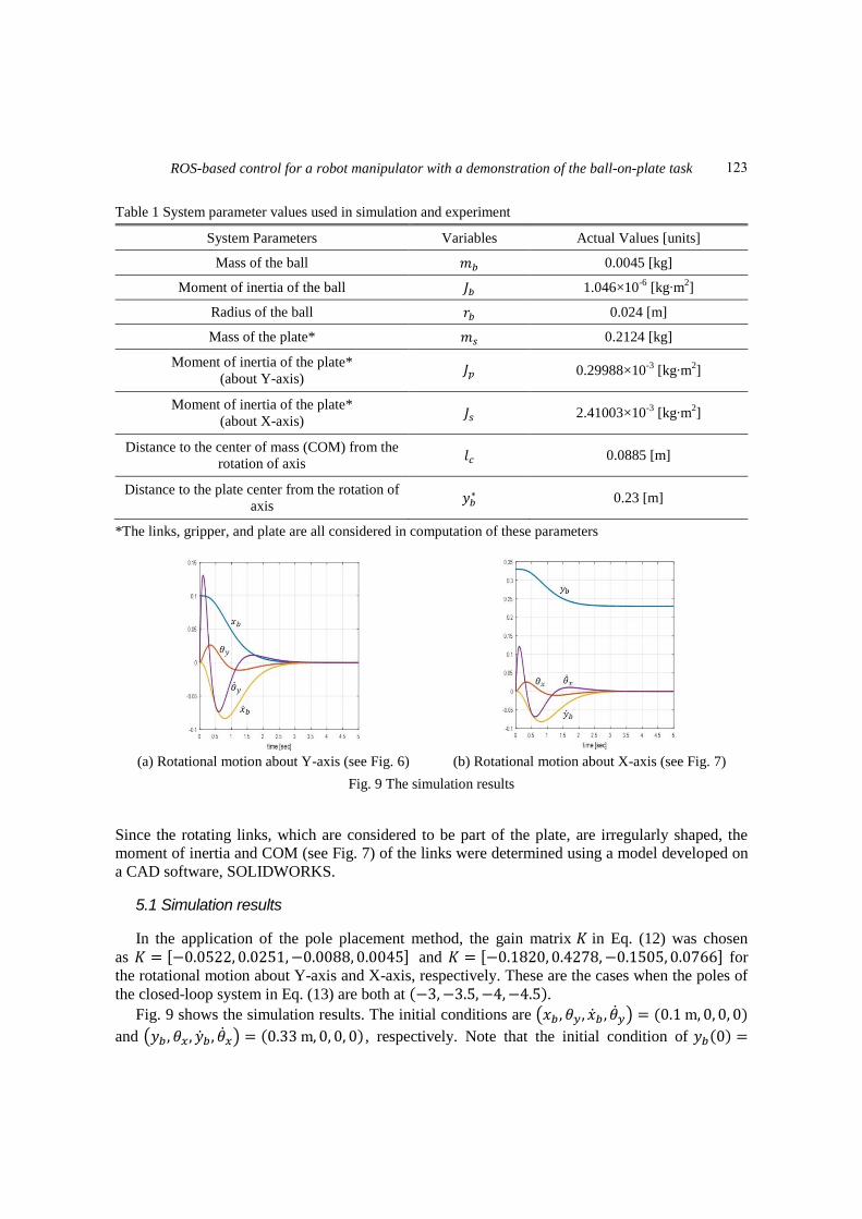
(a) Rotational motion about Y-axis (see Fig. 6) (b) Rotational motion about X-axis (see Fig. 7)
Fig. 9 The simulation results
Since the rotating links, which are considered to be part of the plate, are irregularly shaped, the
moment of inertia and COM (see Fig. 7) of the links were determined using a model developed on
a CAD software, SOLIDWORKS.
5.1 Simulation results
In the application of the pole placement method, the gain matrix 𝐾 in Eq. (12) was chosen
as 𝐾 = [−0.0522, 0.0251,−0.0088, 0.0045] and 𝐾 = [−0.1820, 0.4278,−0.1505, 0.0766] for
the rotational motion about Y-axis and X-axis, respectively. These are the cases when the poles of
the closed-loop system in Eq. (13) are both at (−3,−3.5, −4,−4.5).
Fig. 9 shows the simulation results. The initial conditions are (𝑥𝑏 , 𝜃𝑦, �̇�𝑏 , �̇�𝑦) = (0.1 m, 0, 0, 0)
and (𝑦𝑏 , 𝜃𝑥, �̇�𝑏 , �̇�𝑥) = (0.33 m, 0, 0, 0), respectively. Note that the initial condition of 𝑦𝑏(0) =
123
Khasim A. Khan, Revanth R. Konda and Ji-Chul Ryu
0.33 m implies the ball is to be at 0.1 m from the center of the plate. As expected, the ball is
stabilized to the center of the plate where (𝑥𝑏∗ , 𝑦𝑏
∗) = (0, 0.23) with eventual zero velocity of the
ball.
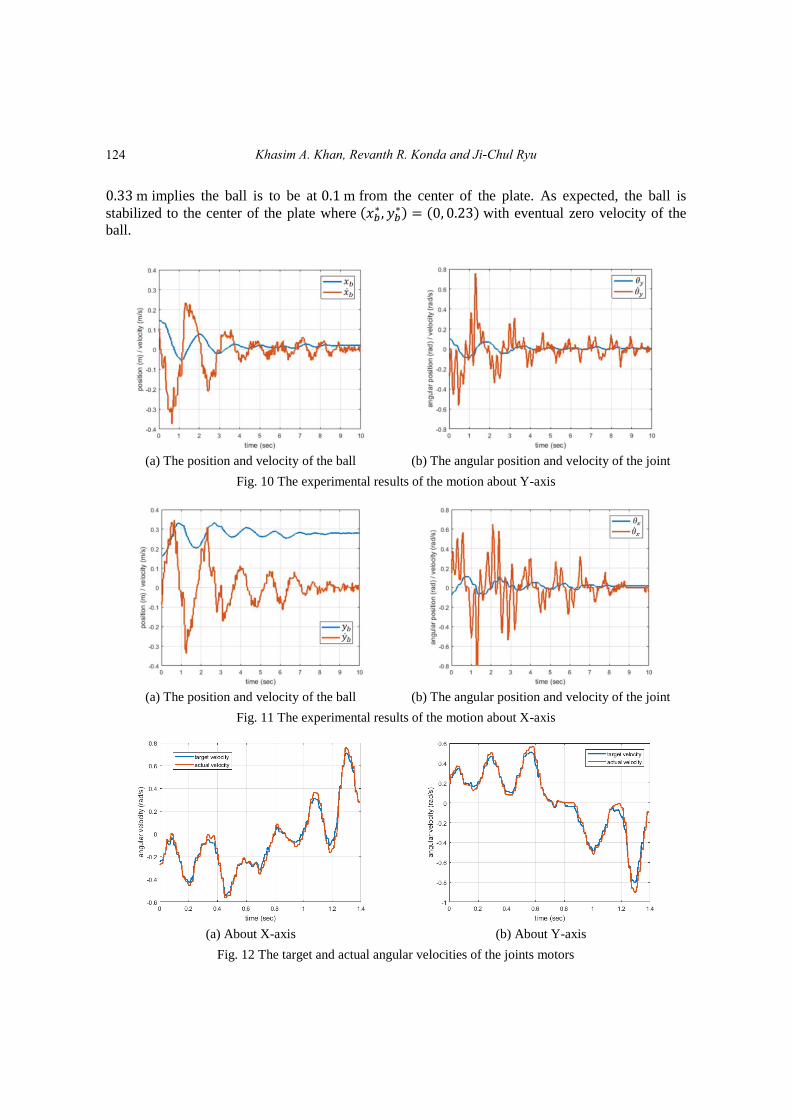
(a) The position and velocity of the ball (b) The angular position and velocity of the joint
Fig. 10 The experimental results of the motion about Y-axis
(a) The position and velocity of the ball (b) The angular position and velocity of the joint
Fig. 11 The experimental results of the motion about X-axis
(a) About X-axis (b) About Y-axis
Fig. 12 The target and actual angular velocities of the joints motors
124
ROS-based control for a robot manipulator with a demonstration of the ball-on-plate task
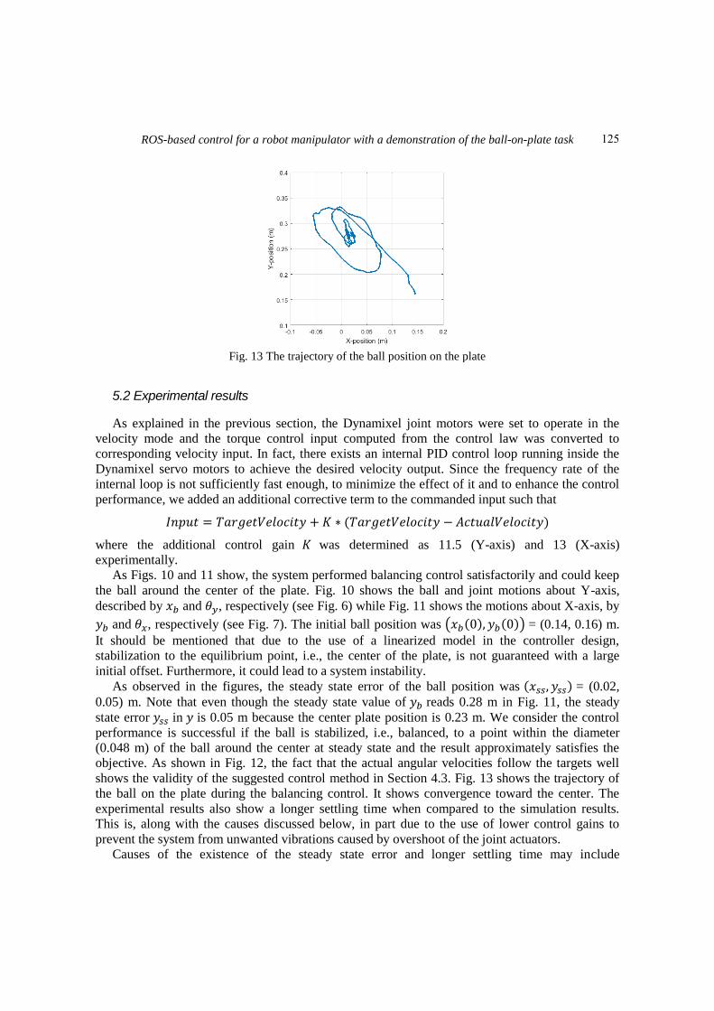
Fig. 13 The trajectory of the ball position on the plate
5.2 Experimental results
As explained in the previous section, the Dynamixel joint motors were set to operate in the
velocity mode and the torque control input computed from the control law was converted to
corresponding velocity input. In fact, there exists an internal PID control loop running inside the
Dynamixel servo motors to achieve the desired velocity output. Since the frequency rate of the
internal loop is not sufficiently fast enough, to minimize the effect of it and to enhance the control
performance, we added an additional corrective term to the commanded input such that
𝐼𝑛𝑝𝑢𝑡 = 𝑇𝑎𝑟𝑔𝑒𝑡𝑉𝑒𝑙𝑜𝑐𝑖𝑡𝑦 + 𝐾 ∗ (𝑇𝑎𝑟𝑔𝑒𝑡𝑉𝑒𝑙𝑜𝑐𝑖𝑡𝑦 − 𝐴𝑐𝑡𝑢𝑎𝑙𝑉𝑒𝑙𝑜𝑐𝑖𝑡𝑦)
where the additional control gain 𝐾 was determined as 11.5 (Y-axis) and 13 (X-axis)
experimentally.
As Figs. 10 and 11 show, the system performed balancing control satisfactorily and could keep
the ball around the center of the plate. Fig. 10 shows the ball and joint motions about Y-axis,
described by 𝑥𝑏 and 𝜃𝑦, respectively (see Fig. 6) while Fig. 11 shows the motions about X-axis, by
𝑦𝑏 and 𝜃𝑥, respectively (see Fig. 7). The initial ball position was (𝑥𝑏(0), 𝑦𝑏(0)) = (0.14, 0.16) m.
It should be mentioned that due to the use of a linearized model in the controller design,
stabilization to the equilibrium point, i.e., the center of the plate, is not guaranteed with a large
initial offset. Furthermore, it could lead to a system instability.
As observed in the figures, the steady state error of the ball position was (𝑥𝑠𝑠, 𝑦𝑠𝑠) = (0.02,
0.05) m. Note that even though the steady state value of 𝑦𝑏 reads 0.28 m in Fig. 11, the steady
state error 𝑦𝑠𝑠 in 𝑦 is 0.05 m because the center plate position is 0.23 m. We consider the control
performance is successful if the ball is stabilized, i.e., balanced, to a point within the diameter
(0.048 m) of the ball around the center at steady state and the result approximately satisfies the
objective. As shown in Fig. 12, the fact that the actual angular velocities follow the targets well
shows the validity of the suggested control method in Section 4.3. Fig. 13 shows the trajectory of
the ball on the plate during the balancing control. It shows convergence toward the center. The
experimental results also show a longer settling time when compared to the simulation results.
This is, along with the causes discussed below, in part due to the use of lower control gains to
prevent the system from unwanted vibrations caused by overshoot of the joint actuators.
Causes of the existence of the steady state error and longer settling time may include
125
Khasim A. Khan, Revanth R. Konda and Ji-Chul Ryu
discrepancy between the actual and simplified decoupled dynamics, invalidity of the small angle
assumption for the linearized model, delays in image processing and command communication,
insufficient control loop rate, and unwanted dynamics introduced by the flexible foam plate chosen
due to the payload limitation. It should be mentioned that since the end goal of this work was to
program a software framework based on ROS under which a manipulator system could perform
various complex tasks, emphasis was not strongly laid on the minimization of the steady state error
and the settling time.
6. Conclusions
This paper presents a ROS-based multi-platform interface to control a 7-DOF manipulator arm
integrated with a vision tracking system. This system is developed in such a way that the
components communicate with each other to receive the state feedback from the vision system and
Dynamixel servo motors, and to compute and send control commands to perform prescribed
control tasks. For a demonstration purpose, the task of balancing a ball on a plate was performed
through simulation and experiment. The experimental results are satisfactory as the system could
balance the ball in a small neighborhood of the plate center. The presented system with the
proposed approaches could be used for more complicated tasks requiring more number of joint
control as well as for a testbed for students to learn ROS programming with control theories in
robotics.
References Allgeuer, P. and Schwarz, M. (2013), “A ROS-based software framework for the NimbRo-OP humanoid
open platform”, Proceedings of the IEEE-RAS International Conference on Humanoid Robots, Atlanta,
Georgia, U.S.A., October.
Araújo, A., Portugal, D., Couceiro, M.S. and Rocha, R.P. (2014), “Integrating Arduino-based educational
mobile robots in ROS”, J. Intell. Robot. Syst. Theor. Appl., 77(2), 281-298.
Awtar, S., Bernard, C., Boklund, N., Master, A., Ueda, D. and Craig, K. (2002), “Mechatronic design of a
ball-on-plate balancing system”, Mechatronics, 12(2), 217-228.
Baggio, D.L., Emami, S., Escriva, D.M., Levgen, K., Mahmood, N., Saragih, J. and Shilkrot, R. (2012),
Masterinng OpenCV with Practical Computer Vision Projects, Packt Publishing, Birmingham, U.K.
Benaroya, H. and Nagurka, M.L. (2010), Mechanical Vibration: Analysis, Uncertainties, and Control, CRC
Press, Boca Raton, Florida, U.S.A.
Bolívar-Vincenty, C.G. and Beauchamp-Báez, G. (2014), “Modelling the ball-and-beam system from
Newtonian mechanics and from Lagrange methods”, Proceedings of 12th Latin American and Caribbean
Conference for Engineering and Technology (LACCEI’2014), Guayaquil, Ecuador, July.
Bonarini, A., Matteucci, M., Migliavacca, M. and Rizzi, D. (2014), “R2P: An open source hardware and
software modular approach to robot prototyping”, Robot Auton. Syst., 62(7), 1073-1084.
DeMarco, K., West, M.E. and Collins, T.R. (2011), “An implementation of ROS on the Yellowfin
autonomous underwater vehicle (AUV)”, Proceedings of the Oceans 2011, Waikoloa, Hawaii, U.S.A.,
September.
Dong, X., Zhao, Y., Xu, Y., Zhang, Z. and Shi, P. (2011), “Design of PSO fuzzy neural network control for
ball and plate system”, J. Innov. Comput. Inf. Control, 7(12), 7091-7103.
Fan, X., Zhang, N. and Teng, S. (2004), “Trajectory planning and tracking of ball and plate system using
hierarchical fuzzy control scheme”, Fuzzy Set. Syst., 144(2), 297-312.
Ghiasi, A.R. and Jafari, H. (2012), “Optimal robust controller design for the ball and plate system”,
126
ROS-based control for a robot manipulator with a demonstration of the ball-on-plate task
Proceedings of the 9th International Conference on Electronics, Computer and Computation, Ankara,
Turkey, November.
Ho, M.T., Rizal, Y. and Chu, L.M. (2013), “Visual servoing tracking control of a ball and plate system:
design, implementation and experimental validation”, J. Adv. Robot. Syst., 10(7), 287.
Hornung, A., Phillips, M., Gil Jones, E., Bennewitz, M., Likhachev, M. and Chitta, S. (2012), “Navigation in
three-dimensional cluttered environments for mobile manipulation”, Proceedings of the IEEE
International Conference on Robotics and Automation, St. Paul, Minnesota, U.S.A., May.
Khan, K. and Ryu, J.C. (2017), “ROS-based control of manipulator arm for balancing a ball on a plate”,
Proceedings of the ASEE Annual Conference & Exposition, Columbus, Ohio, U.S.A., June.
Knuplei, A., Chowdhury, A. and Sveeko, R. (2003), “Modelling and control design for the ball and plate
system”, Proceedings of the International Conference on Industrial Technology, Maribor, Slovenia,
December.
Korpela, C.M., Danko, T.W. and Oh, P.Y. (2012), “MM-UAV: Mobile manipulating unmanned aerial
vehicle”, J. Intell. Robot. Syst. Theor. Appl., 65(1-4), 93-101.
Liu, H. and Liang, Y. (2010), “Trajectory tracking sliding mode control of ball and plate system”,
Proceedings of the 2nd International Asian Conference on Informatics in Control, Automation and
Robotics, Wuhan, China, March.
Martinez, A. and Fernández, E. (2013), Learning ROS for Robotics Programming, Packt Publishing,
Birmingham, U.K.
Meeussen, W., Wise, M. and Glaser, S. (2010), “Autonomous door opening and plugging in with a personal
robot”, Proceedings of the IEEE International Conference on Robotics and Automation, Anchorage,
Alaska, U.S.A., May.
Mochizuki, S. and Ichihara, H. (2013), “I-PD Controller design based on generalized KYP Lemma for ball
and plate system”, Proceedings of the IEEE European Control Conference, Zurich, Switzerland, July.
Quigley, M., Berkey, B., Conley, K., Faust, J., Foote, T., Leibs, J., Berger, E., Wheeler, R. and Ng, A.
(2009), “ROS: An open-source Robot Operating System”, Proceedings of the ICRA Workshop on Open
Source Software, Kobe, Japan, May.
ROS Wiki (2007), Dynamixel Motor; Robot Operating System (ROS),
<http:/wiki.ros.org/dynamixel_motor>.
Santos, J.M., Portugal, D. and Rocha, R.P. (2013), “An evaluation of 2D SLAM techniques available in
Robot Operating System”, Proceedings of the IEEE International Symposium on Safety, Security, and
Rescue Robotics, Linkoping, Sweden, October.
Wang, H., Tian, Y., Fu, S. and Zhen, S. (2008), “Nonlinear control for output regulation of ball and plate
system”, Proceedings of the 27th Chinese Control Conference, Junming, China, July.
Zheng, F., Li, X., Qian, X. and Wang, S. (2011), “Modeling and PID neural network research for the ball
and plate system”, Proceedings of the International Conference on Electronics, Communications and
Control, Ningbo, China, September.
CC
127