Embed Size (px)
Citation preview
1
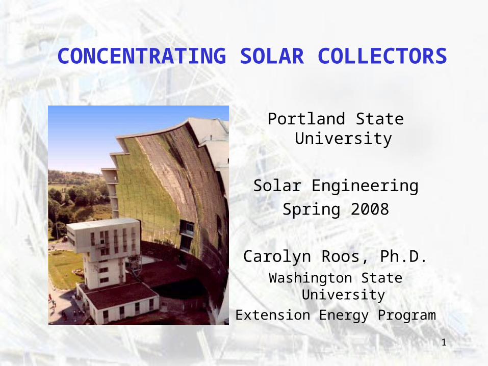
CONCENTRATING SOLAR COLLECTORS
Portland State University
Solar Engineering
Spring 2008
Carolyn Roos, Ph.D.Washington State University
Extension Energy Program
2
OUTLINE
• A review of six concentrating solar technologies and current projects.
• Basics of ray tracing.
• Sketch of a thermal analysis example
3
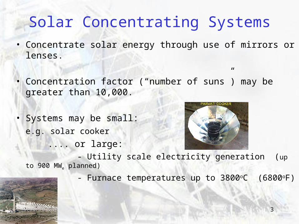
Solar Concentrating Systems
• Concentrate solar energy through use of mirrors or lenses.
• Concentration factor (“number of suns”) may be greater than 10,000.
• Systems may be small:
e.g. solar cooker
.... or large: - Utility scale electricity generation (up to 900 MWe planned)
- Furnace temperatures up to 3800oC (6800oF)
4
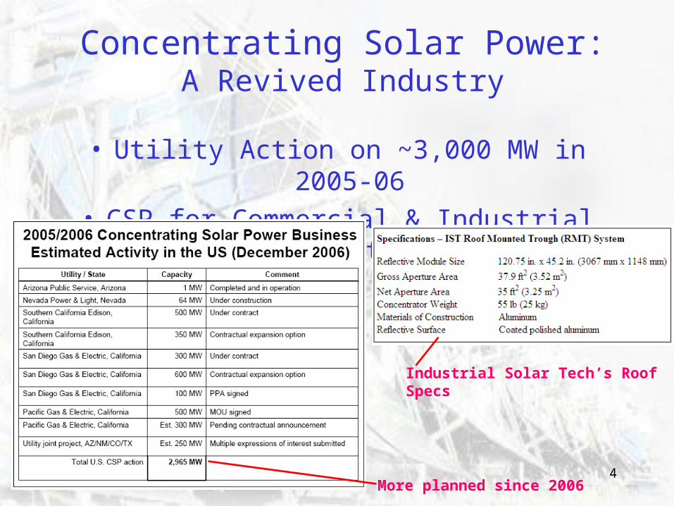
Concentrating Solar Power:A Revived Industry
• Utility Action on ~3,000 MW in 2005-06• CSP for Commercial & Industrial Facilities
Industrial Solar Tech’s Roof Specs
More planned since 2006
5
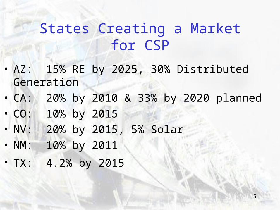
States Creating a Market for CSP
• AZ: 15% RE by 2025, 30% Distributed Generation• CA: 20% by 2010 & 33% by 2020 planned• CO: 10% by 2015• NV: 20% by 2015, 5% Solar• NM: 10% by 2011
• TX: 4.2% by 2015
6
In a Carbon Limited Future…
• Carbon limits will close the cost gap.
• CSP can scale up fast without critical bottleneck materials. (e.g. silicon)
• Costs will come down with increase in capacity– expected to fall below natural gas in the next few years.
• In the very near future, the CSP market in the SW US can grow to 1 to 2 GW per year.
From: http://www.nrel.gov/csp/troughnet/pdfs/2007/morse_look_us_csp_market.pdf
7
Examples of CSP ApplicationsPower Generation:
Utility Scale: 64 MW Nevada Solar One (2007) Buildings: 200 kW “Power Roof”
Thermal Needs: Hot Water and Steam (Industrial & Commercial Uses) Air Conditioning – Absorption Chillers Desalination of seawater by evaporation Waste incineration
“Solar Chemistry” Manufacture of metals and semiconductors Hydrogen production (e.g. water splitting)
Materials Testing Under Extreme Conditions e.g. Design of materials for shuttle reentry
8
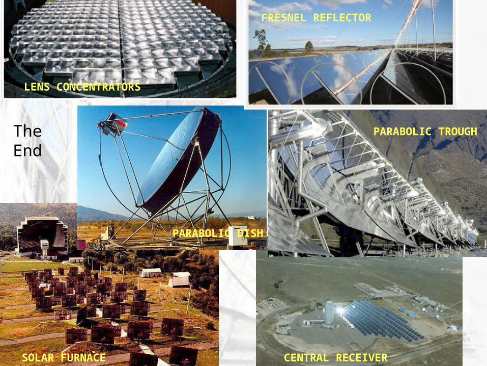
Primary Types of Solar Collectors
1. Parabolic Trough2. Compact Linear Fresnel Reflector new
3. Solar Furnace4. Parabolic Dish & Engine5. Solar Central Receiver
(Solar Power Tower)6. Lens Concentrators
Can be used in conjunction with PV:Use lenses or mirrors in conjunction with PV panels to increase their efficiency.
(http://seattle.bizjournals.com/seattle/stories/2006/04/24/focus2.html)
9
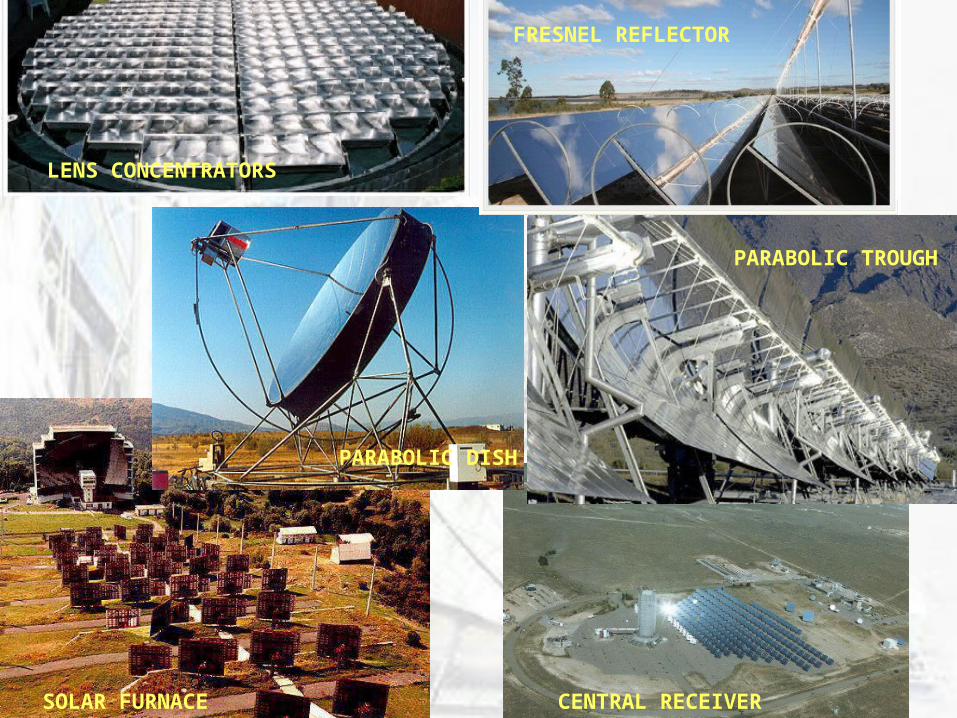
PARABOLIC DISH & ENGINE
SOLAR FURNACE
CENTRAL RECEIVERSOLAR FURNACE
PARABOLIC DISH
PARABOLIC TROUGH
FRESNEL REFLECTOR
LENS CONCENTRATORS
10
Major Components of Solar Collector Systems
• Concentrating mirror(s) May use primary & secondary concentrators.
• Absorber within a ReceiverReceiver contains the absorber. It is the apparatus that “receives” the solar energy; e.g. evacuated tube. Absorber absorbs energy from concentrator and transfers to process being driven (engine, chemical reactor, etc.); e.g. the pipe within an evacuated tube.
• Heliostats Flat or slightly curved mirrors that track the sun and focus on receiver or concentrator. Used with solar furnaces and power towers.
11
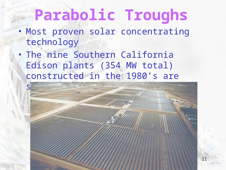
Parabolic Troughs• Most proven solar concentrating technology• The nine Southern California Edison plants
(354 MW total) constructed in the 1980’s are still in operation
12
Parabolic Troughs - Operation
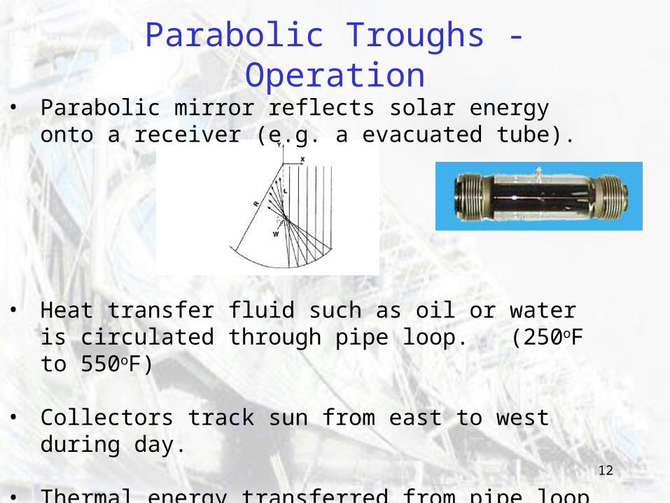
• Parabolic mirror reflects solar energy onto a receiver (e.g. a evacuated tube).
• Heat transfer fluid such as oil or water is circulated through pipe loop. (250oF to 550oF)
• Collectors track sun from east to west during day.
• Thermal energy transferred from pipe loop to process.
13
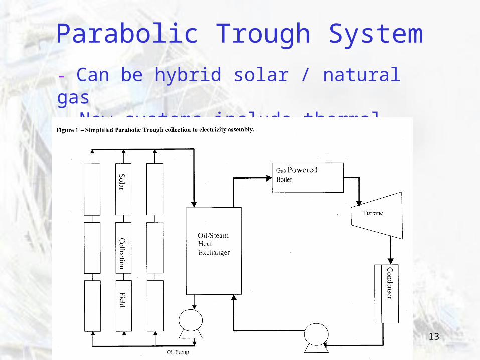
Parabolic Trough System
- Can be hybrid solar / natural gas- New systems include thermal storage.
14
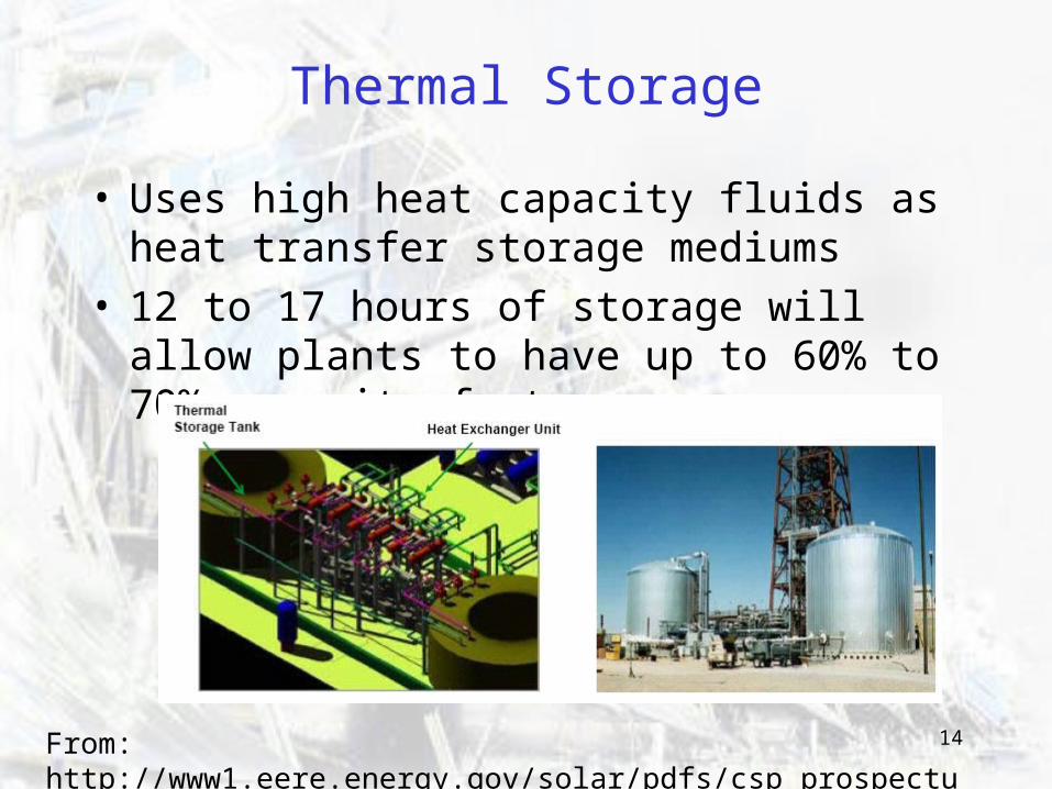
Thermal Storage
• Uses high heat capacity fluids as heat transfer storage mediums
• 12 to 17 hours of storage will allow plants to have up to 60% to 70% capacity factors.
From: http://www1.eere.energy.gov/solar/pdfs/csp_prospectus_112807.pdf
15
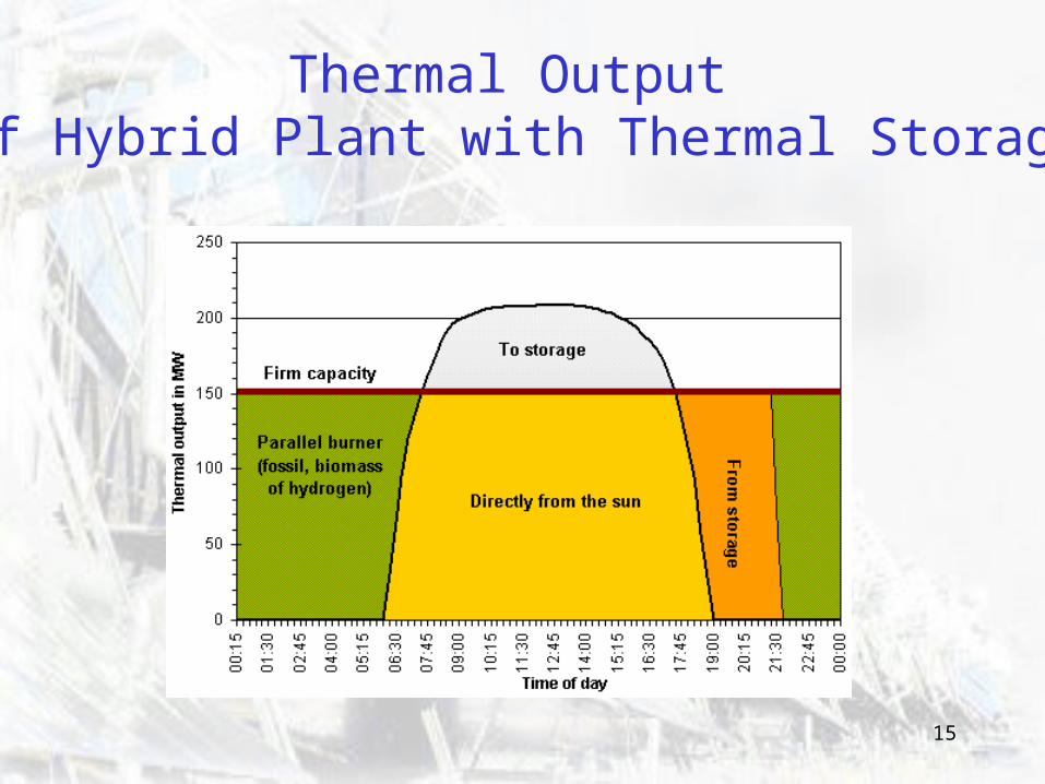
Thermal Output of Hybrid Plant with Thermal Storage
16
What Have Been the Technical Challenges?
Development of Materials Heat transfer tubes that are less prone to sagging & breaking. Improved surface material of heat transfer tubes.
High absorptivity, low emissivity and long-term stability in air. Low cost mirrors that have reflectivity and washability of glass.
Improved Components Flex hoses used to join sections of pipe loop were prone to failure
Replaced with ball joint design. Ability to track on tilted axis
Improved Processes e.g. Generate steam directly instead of running heat transfer fluid
through heat exchanger - Improves efficiency but more difficult to control.
17
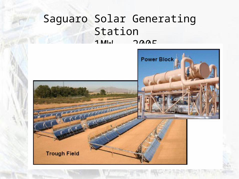
Saguaro Solar Generating Station (north of Tucson) 1MW - Compared to 395MW in natural gas fired generating capacity at same site Broke ground March 24, 2004 and started generating power December 2005 Built by Solargenix, subsidiary of ACCIONA Energy of Spain Arizona has goal of 15% renewable energy by 2025. $6 Million Project
“First Solar Thermal Parabolic Trough Power Plant Built in The U.S. In Nearly Two
Decades to Be Dedicated On Earth Day” (2005)
18
Saguaro Solar Generating Station 1MW - 2005
19
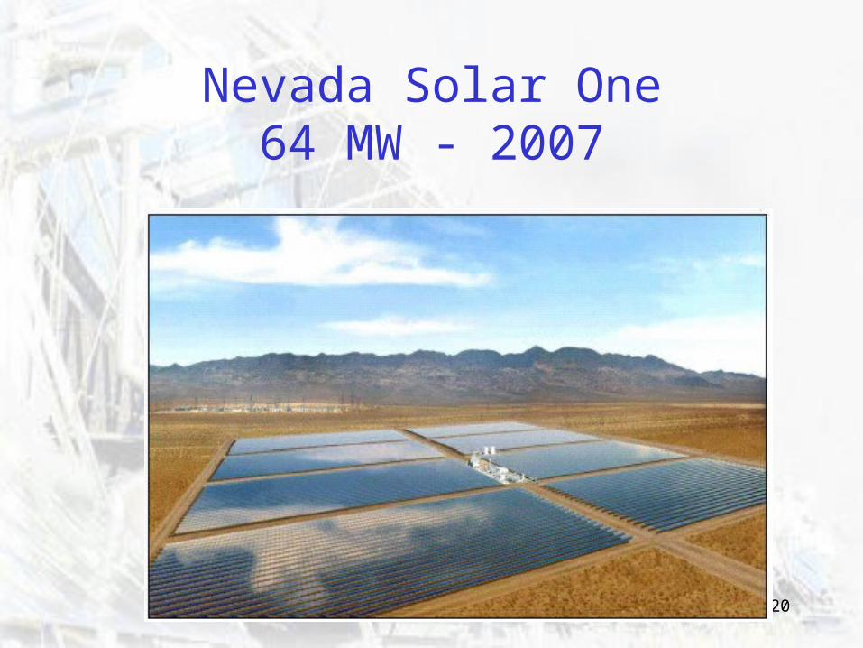
Nevada Solar One64 MW - 2007
• Now producing 64 MW on 140 hectares• Located in Eldorado Valley (south of Las Vegas)• One of the world's largest CSP plants. • Cost: $262 million • Developed by Solargenix Energy.
SHOTT North America provided receivers. • Groundbreaking in February 2006
On line in June 2007.
20
Nevada Solar One64 MW - 2007
21
Around the World
Granada, Spain. • Two 50 MW plants• Developed by Solar Millenium AG
Negev desert of Israel• 150 MW facility to be expanded to 500 MW • Developed by Solel (successor company to Luz) • Cost $1 billion
22
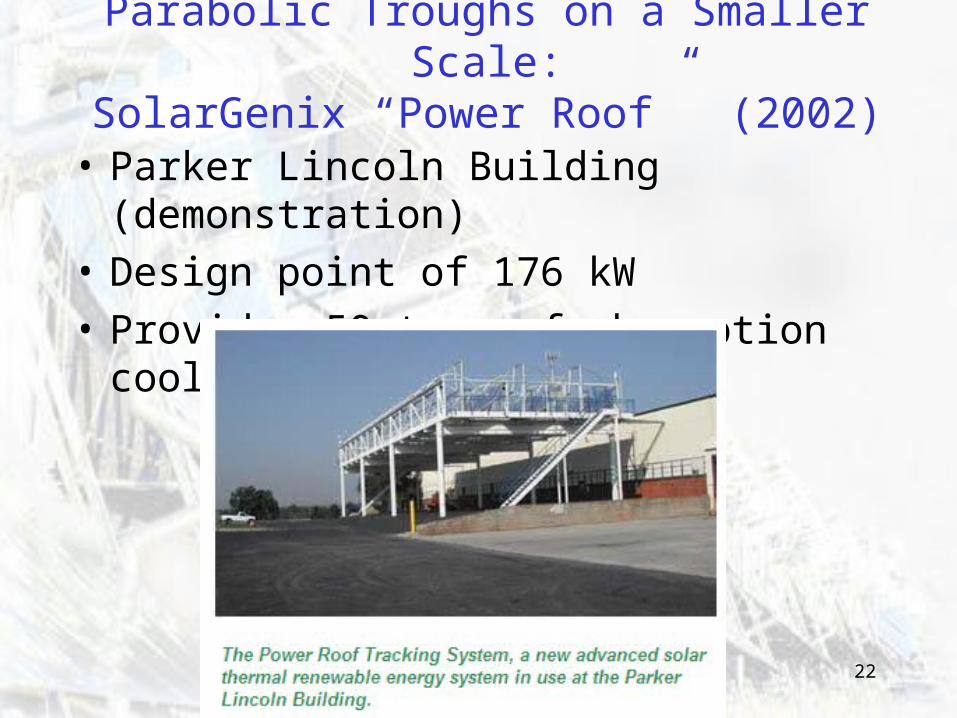
Parabolic Troughs on a Smaller Scale:SolarGenix “Power Roof” (2002)
• Parker Lincoln Building (demonstration)
• Design point of 176 kW
• Provides 50 tons of absorption cooling
23
Parabolic TroughsLinks for More Info
http://www.iea-ship.org/index.html
http://www.solarpaces.org/solar_trough.pdf
http://www.nrel.gov/docs/fy04osti/34440.pdf
Heat Transfer Analysis:
http://www.nrel.gov/docs/fy04osti/34169.pdf
Ball Joint Design:
http://www.eere.energy.gov/troughnet/pdfs/moreno_sf_interconnections_with_salt_htf.pdf
24
Linksto Parabolic Trough
Projects and Technology Examples
http://www.solargenix.com/power_plant_tech.cfmhttp://www.solargenix.com/building_products.cfmhttp://www.us.schott.com/solarthermal/english/index.htmlhttp://www.us.schott.com/solarthermal/english/products/
receiver/details.htmlhttp://www.inderscience.com/search/index.php?
mainAction=search&action=record&rec_id=6745http://www.sete.gr/files/Ebook/2006/
Hospitality_Day_Lokurlu.pdfhttp://www.eere.energy.gov/troughnet/pdfs/
lewandowski_vshot.pdfhttp://www.capitalsungroup.com/files/rmt.pdfhttp://www.industrialsolartech.com/
25
Preview…
• Sketch of thermal analysis and design for parabolic trough system at the end of this presentation.
26
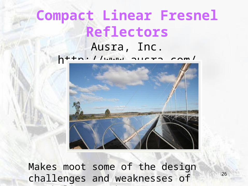
Compact Linear Fresnel ReflectorsAusra, Inc.
http://www.ausra.com/
Makes moot some of the design challenges and weaknesses of parabolic troughs.
27
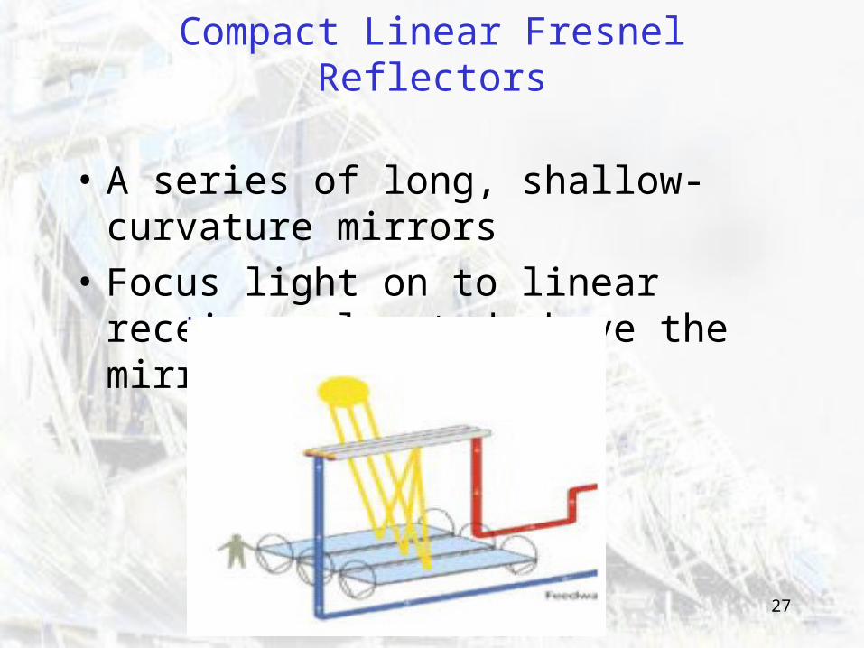
Compact Linear Fresnel Reflectors
• A series of long, shallow-curvature mirrors
• Focus light on to linear receivers located above the mirrors.
28
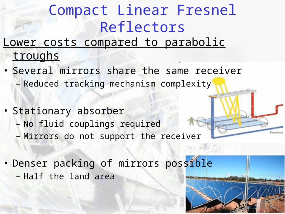
Compact Linear Fresnel Reflectors
Lower costs compared to parabolic troughs• Several mirrors share the same receiver
– Reduced tracking mechanism complexity
• Stationary absorber– No fluid couplings required– Mirrors do not support the receiver
• Denser packing of mirrors possible– Half the land area
29
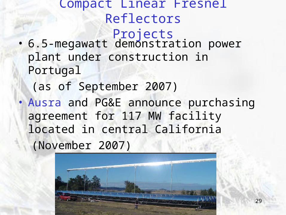
• 6.5-megawatt demonstration power plant under construction in Portugal
(as of September 2007)• Ausra and PG&E announce purchasing
agreement for 117 MW facility located in central California
(November 2007)
Compact Linear Fresnel ReflectorsProjects
30
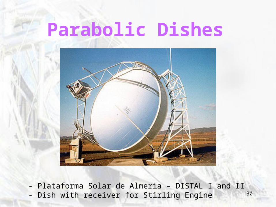
Parabolic Dishes
- Plataforma Solar de Almeria – DISTAL I and II- Dish with receiver for Stirling Engine
31
Parabolic Dish/Engine - Operation
• Solar energy drives a Stirling engine or Brayton cycle engine (gas turbine.)
• Receiver absorbs solar energy and transfers it to the engine’s working fluid.
• Systems are easily hybridized since Stirling engines can run on any external heat source.
32
State of Dish TechnologyMature and Cost Effective Technology: Large utility projects using parabolic dishes are now under development.
Technical Challenges Have Been: Development of solar materials and components Commercial availability of a solar-izable engine.
Advantage: High Efficiency Demonstrated highest solar-to-electric conversion efficiency
(still true with advances in CPV? No.) Potential to become one of least expensive sources of renewable energy. (still true with development of Fresnel reflectors?)
Advantage: Flexibility Modular - May be deployed individually for remote applications or grouped together for small-grid (village power) systems.
33
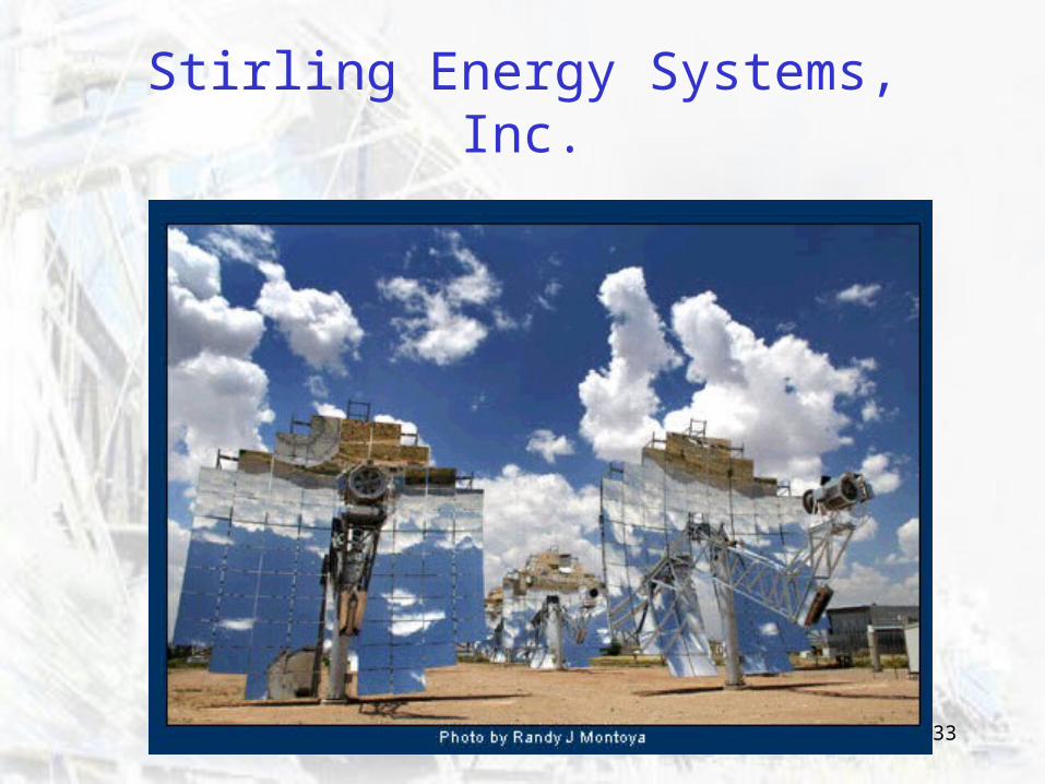
Stirling Energy Systems, Inc.
34
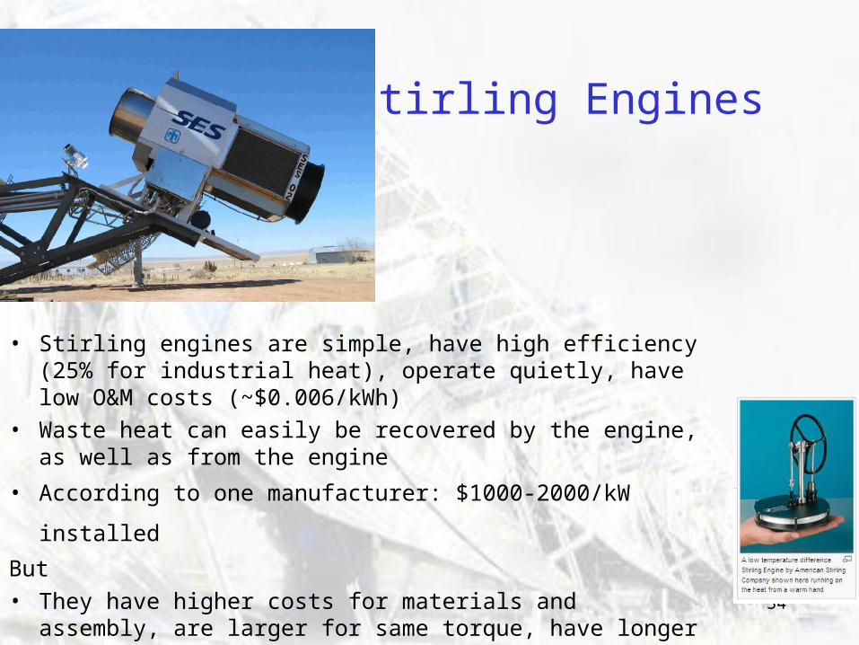
Stirling Engines
• Stirling engines are simple, have high efficiency (25% for industrial heat), operate quietly, have low O&M costs (~$0.006/kWh)
• Waste heat can easily be recovered by the engine, as well as from the engine
• According to one manufacturer: $1000-2000/kW installed But• They have higher costs for materials and assembly, are larger
for same torque, have longer start up time (needs to warm up)
35
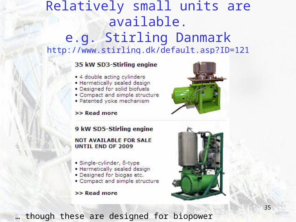
Relatively small units are available.e.g. Stirling Danmark
http://www.stirling.dk/default.asp?ID=121
… though these are designed for biopower
36
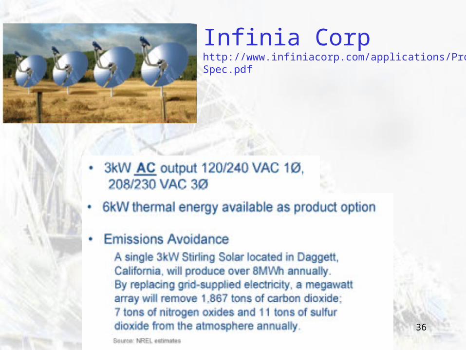
Infinia Corphttp://www.infiniacorp.com/applications/Prod_Spec.pdf
37
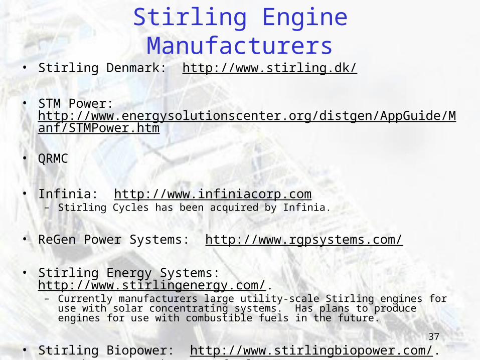
Stirling Engine Manufacturers• Stirling Denmark: http://www.stirling.dk/
• STM Power: http://www.energysolutionscenter.org/distgen/AppGuide/Manf/STMPower.htm
• QRMC
• Infinia: http://www.infiniacorp.com – Stirling Cycles has been acquired by Infinia.
• ReGen Power Systems: http://www.rgpsystems.com/
• Stirling Energy Systems: http://www.stirlingenergy.com/. – Currently manufacturers large utility-scale Stirling engines for use with solar
concentrating systems. Has plans to produce engines for use with combustible fuels in the future.
• Stirling Biopower: http://www.stirlingbiopower.com/. – In the start up phase (as of July 2007)
38
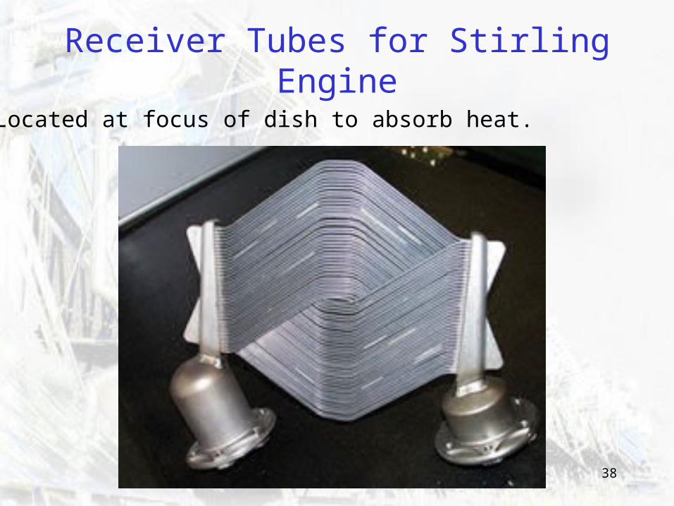
Receiver Tubes for Stirling Engine
Located at focus of dish to absorb heat.
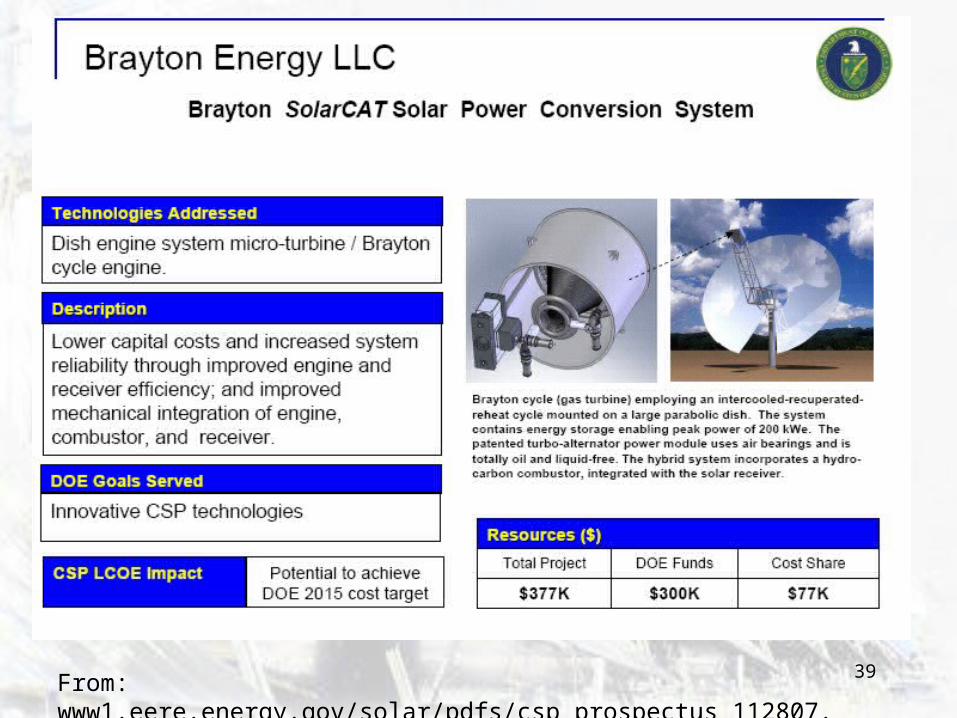
39From: www1.eere.energy.gov/solar/pdfs/csp_prospectus_112807.pdf
40
SDG&E (2005) 300 MW From 12,000 Stirling Solar Dishes
in Imperial Valley, Southern CA
• San Diego Gas & Electric entered 20-year contract with SES Solar Two, an affiliate of Stirling Energy Systems in 2005.
• 12,000 Stirling solar dishes providing 300 MW on three square miles
• Two future phases possible that could add 600 MW– At 900 MW would be one of the largest solar facilities in the world.
41
SCE (2005) 500 MW from 20,000-Dish Array
in Mojave Desert• Southern California Edison will construct 500
MW solar generating station on 4500 acres:– Approved by CPUC in Dec 2005– Using SES dishes
• First phase: 20,000-dish array to be constructed over four years
• Option to expand to 850 MW.
42
A news story on these two projects…
• SAN DIEGO, California, US, September 14, 2005 (Refocus Weekly) An electric utility in California will buy 300 MW of solar power from a new facility that uses Stirling solar dishes.
• San Diego Gas & Electric will buy the green power under a 20-year contract with SES Solar Two, an affiliate of Stirling Energy Systems of Arizona. The 300 MW solar facility will consists of 12,000 Stirling solar dishes on three square miles of land in the Imperial Valley of southern California.
SDG&E has options on two future phases that could add another 600 MW of renewables capacity and, if the plant grows to 900 MW within ten years, it would be one of the largest solar facilities in the world. The utility also announced the purchase of 4 MW of energy from a local biogas landfill project.
SES says the contract is the second record-breaking solar project it has signed in the past month, following a contract with Southern California Edison for construction of a 4,500 acre solar generating station in southern California. That 20-year power purchase agreement, which also must be approved by the CPUC, calls for development of 500 MW of solar capacity in the Mojave Desert, northeast of Los Angeles.
The first phase will consist of a 20,000-dish array to be constructed over four years, with an option to expand the project to 850 MW.
43
Salt River Landfill Demonstration ProjectFour 22 kW SunDishes
• Each 'SunDish' is 50' high.
• Stretched-membrane faceted dishes deflected to convex form by vacuum.
• Reflective surface is made of sheets of 1.0 mm low-iron glass.• • Stirling engines and generators manufactured by STM Corporation.
• Electricity is used by the landfill facilities.
• Efficiency is “20% higher than other solar systems of a similar size.”
• Hybrid system: Stirling engines can run on solar energy, landfill gas or other liquid or gaseous fuels.
44
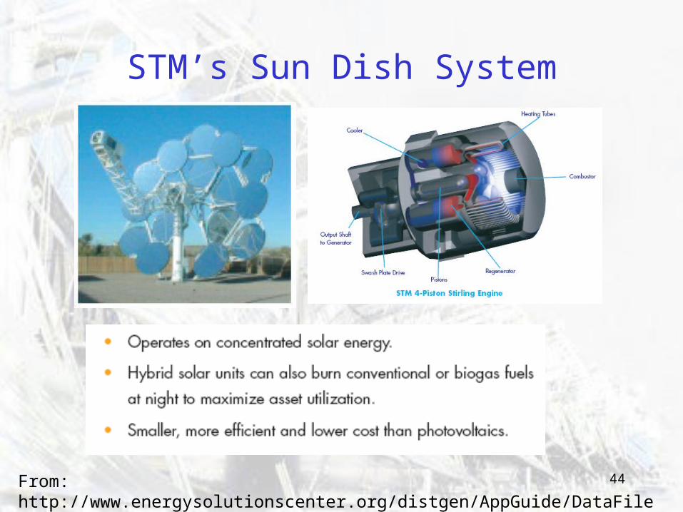
STM’s Sun Dish System
From: http://www.energysolutionscenter.org/distgen/AppGuide/DataFiles/STMBrochure.pdf
45
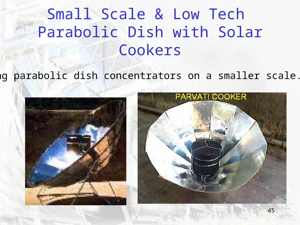
Small Scale & Low Tech Parabolic Dish with Solar Cookers
Using parabolic dish concentrators on a smaller scale...
46
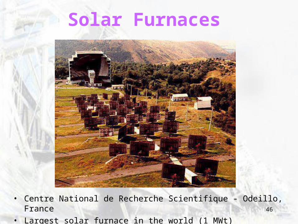
Solar Furnaces
• Centre National de Recherche Scientifique - Odeillo, France• Largest solar furnace in the world (1 MWt)
47
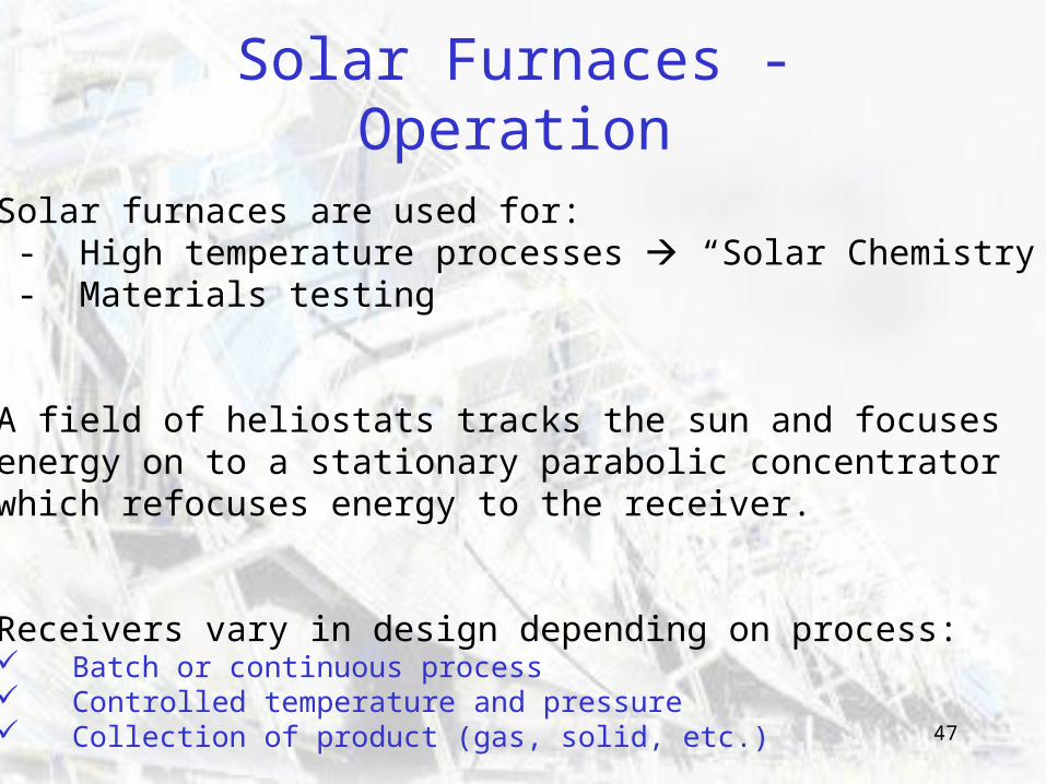
Solar Furnaces - Operation
Solar furnaces are used for: - High temperature processes “Solar Chemistry” - Materials testing
A field of heliostats tracks the sun and focuses energy on to a stationary parabolic concentrator which refocuses energy to the receiver.
Receivers vary in design depending on process: Batch or continuous process Controlled temperature and pressure Collection of product (gas, solid, etc.)
48
Why Run Processes in a Solar Furnace?
Higher Temperatures (up to 3800oC) Higher temperatures are possible in solar furnace than in conventional combustion furnace or electric arc furnace.
Cleaner Processes e.g. Electric arc furnaces use carbon electrodes which often contaminate product.
Energy Sustainability Use of renewable energy for industrial processes.
49
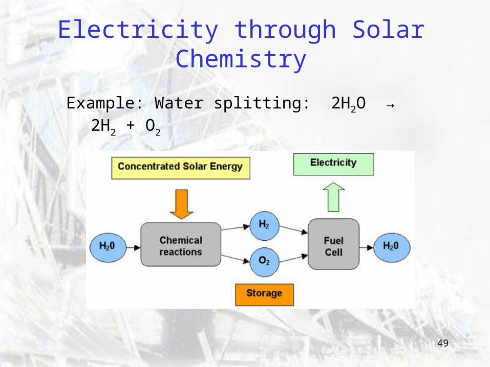
Electricity through Solar Chemistry
Example: Water splitting: 2H2O → 2H2 + O2
50
Solar FurnacesTechnical Challenges
From test bench to commercial scale processes Development of continuous processes from batch experiments
Material Development Materials suitable for very high temperatures.
Process Control e.g. Accurate measurement of high temperatures
51
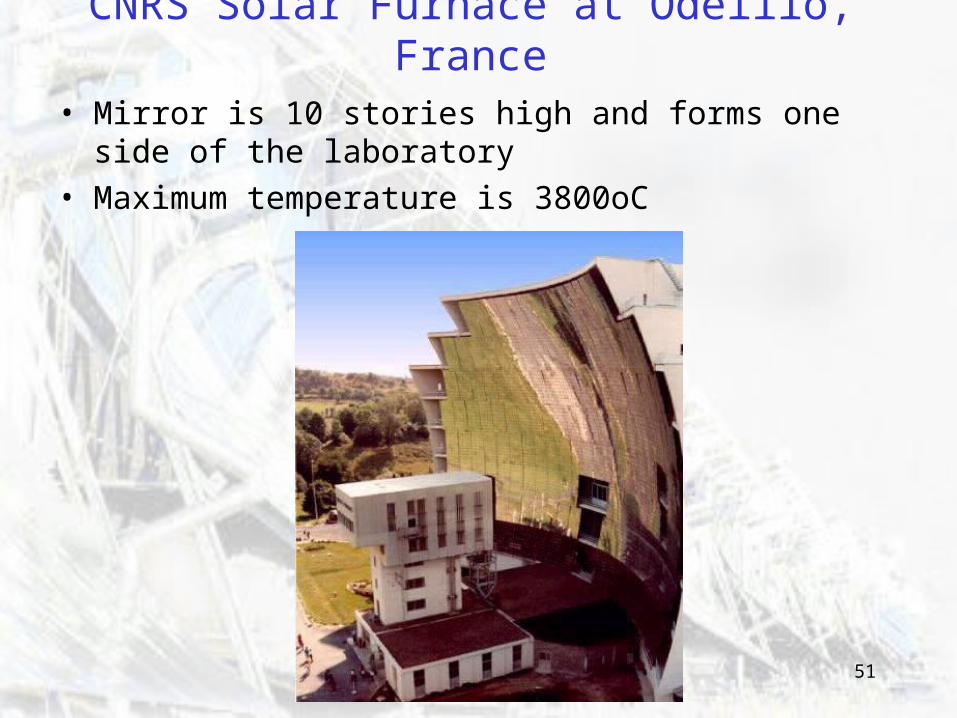
CNRS Solar Furnace at Odeillo, France
• Mirror is 10 stories high and forms one side of the laboratory
• Maximum temperature is 3800oC
52
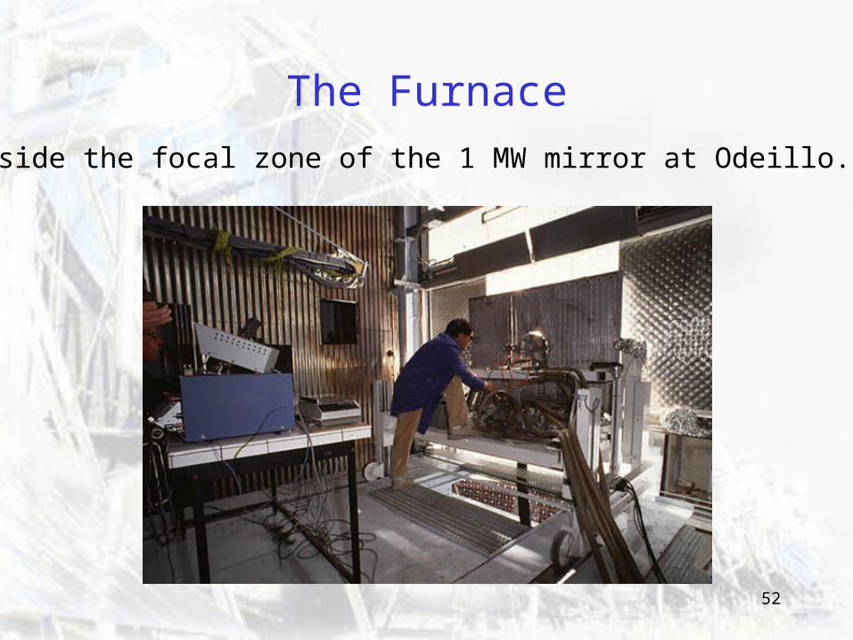
The Furnace
Inside the focal zone of the 1 MW mirror at Odeillo.
53
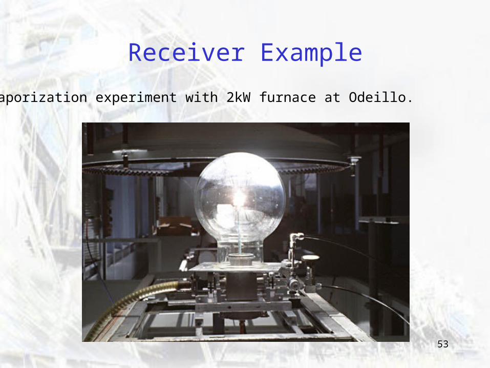
Receiver Example
Vaporization experiment with 2kW furnace at Odeillo.
54
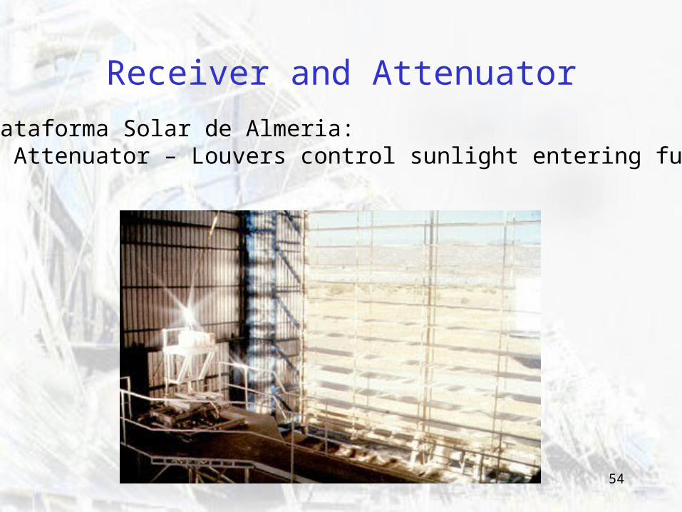
Receiver and Attenuator
Plataforma Solar de Almeria: - Attenuator – Louvers control sunlight entering furnace
55
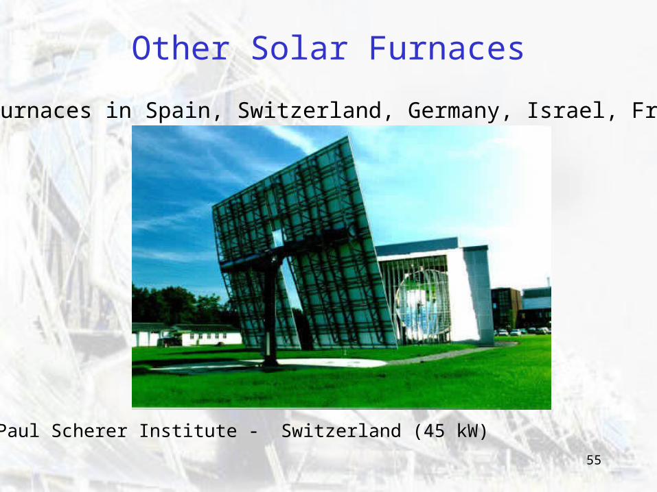
Other Solar Furnaces
Solar furnaces in Spain, Switzerland, Germany, Israel, France...
Paul Scherer Institute - Switzerland (45 kW)
56
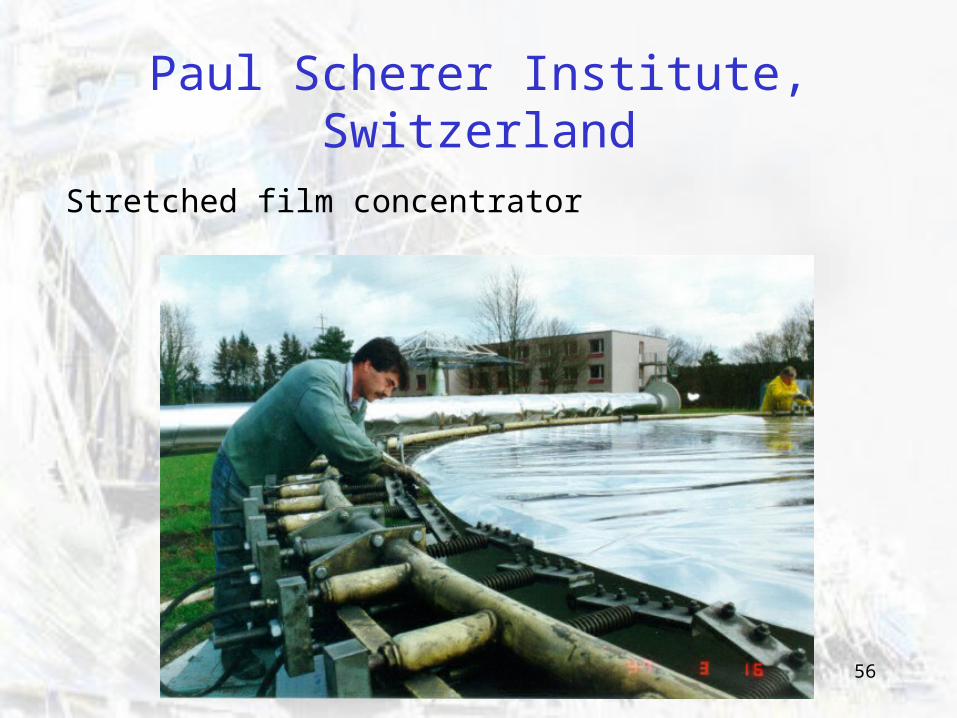
Paul Scherer Institute, Switzerland
Stretched film concentrator
57
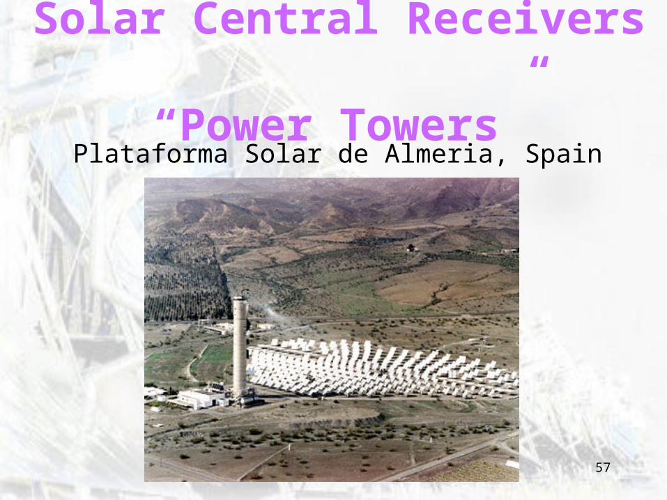
Solar Central Receivers “Power Towers”
Plataforma Solar de Almeria, Spain
58
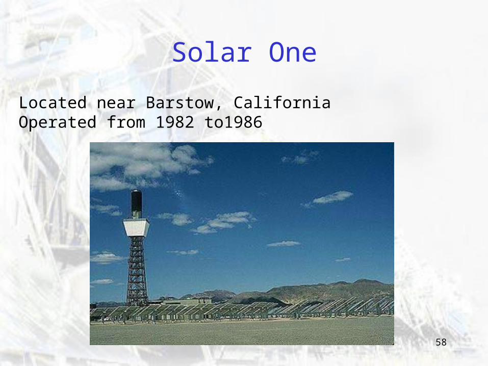
Solar One
Located near Barstow, California Operated from 1982 to1986
59
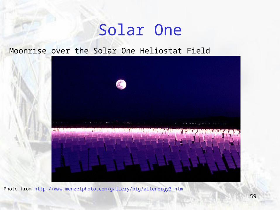
Solar OneMoonrise over the Solar One Heliostat Field
Photo from http://www.menzelphoto.com/gallery/big/altenergy3.htm
60
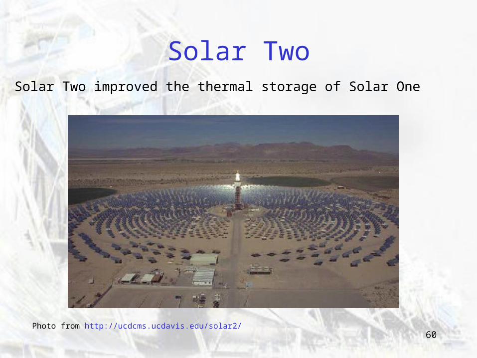
Solar TwoSolar Two improved the thermal storage of Solar One
Photo from http://ucdcms.ucdavis.edu/solar2/
61
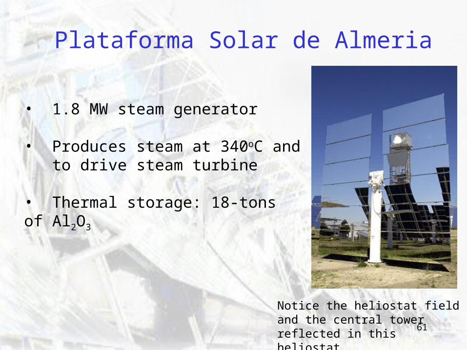
Plataforma Solar de Almeria
• 1.8 MW steam generator
• Produces steam at 340oC and to drive steam turbine
• Thermal storage: 18-tons of Al2O3
Notice the heliostat field and the central tower reflected in this heliostat.
62
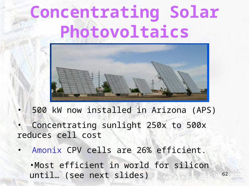
Concentrating Solar Photovoltaics
• 500 kW now installed in Arizona (APS)
• Concentrating sunlight 250x to 500x reduces cell cost
• Amonix CPV cells are 26% efficient.
•Most efficient in world for silicon until… (see next slides)
• With multi-junction cells, efficiency can be increased to 40%
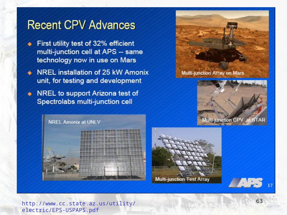
63http://www.cc.state.az.us/utility/electric/EPS-USPAPS.pdf
64
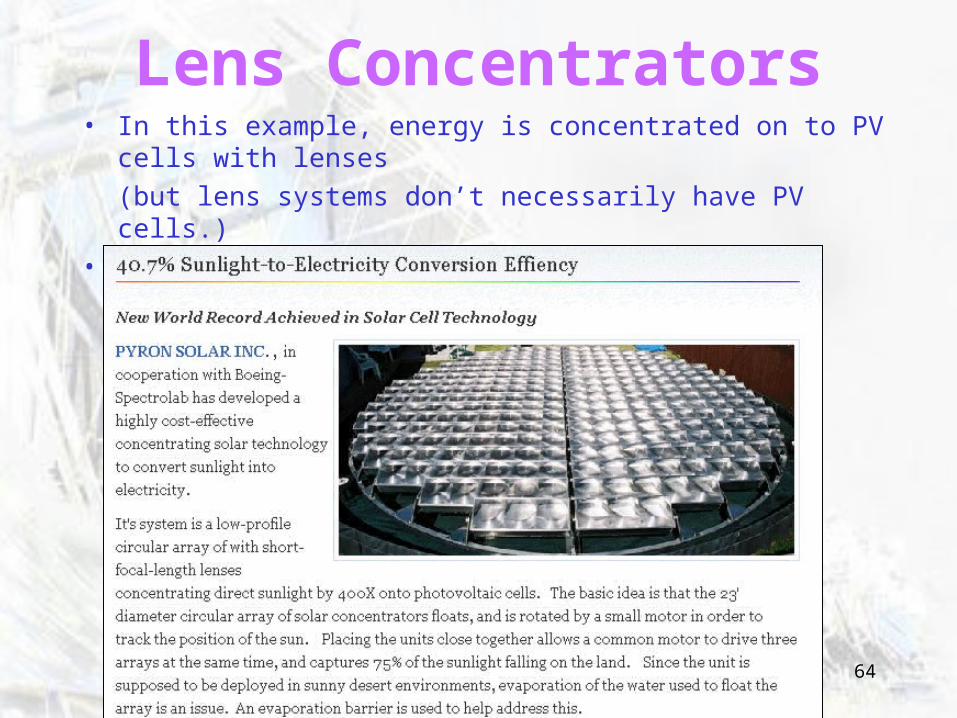
Lens Concentrators• In this example, energy is concentrated on to PV cells with lenses
(but lens systems don’t necessarily have PV cells.)• 40% efficiency for CPV achieved.
65
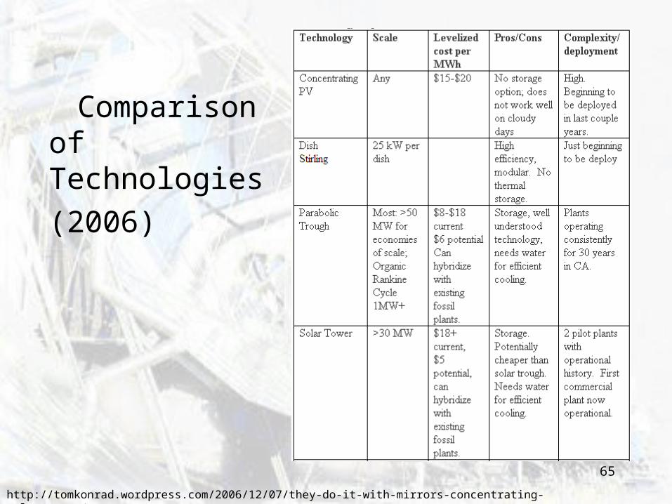
Comparison of Technologies
(2006)
http://tomkonrad.wordpress.com/2006/12/07/they-do-it-with-mirrors-concentrating-solar-power/
66
Environmental Impacts
Deserts have sensitive ecosystems and low water availability.
Land UseThe heliostat field occupies a large area of land, shading areas where the ecosystem is accustomed to full sun. -
Water Use Wet cooling towers used in power generation have high water consumption.
67
• Geometrical Optics: – Law of Reflection and Refraction are the
only physical laws required for geometrical optics.
– The rest is geometry How rays of light are reflected off surfaces or refracted through materials.
Ray Tracing
68
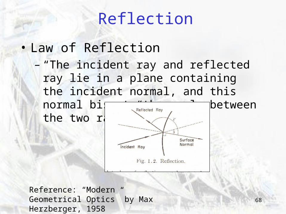
• Law of Reflection– “The incident ray and reflected ray lie in a
plane containing the incident normal, and this normal bisects the angle between the two rays.”
Reflection
Reference: “Modern Geometrical Optics” by Max Herzberger, 1958
69
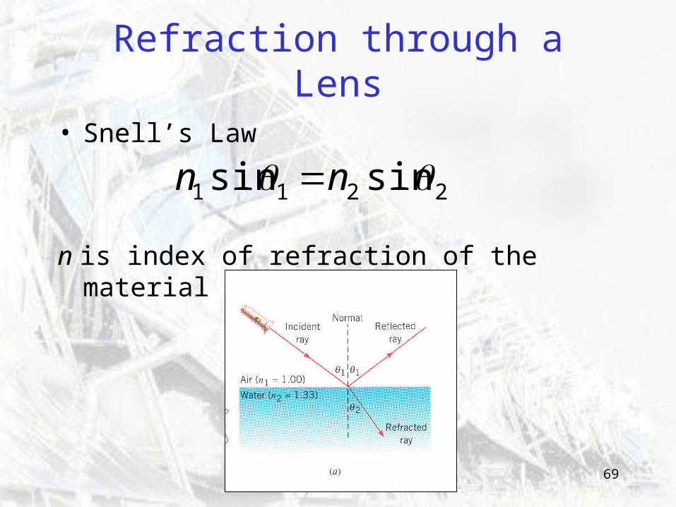
Refraction through a Lens
• Snell’s Law
n is index of refraction of the material
2211 sinsin nn
70
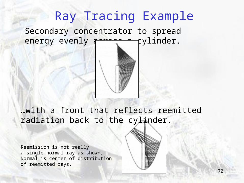
Ray Tracing Example
Secondary concentrator to spread energy evenly across a cylinder.
…with a front that reflects reemitted radiation back to the cylinder.
Reemission is not really a single normal ray as shown, Normal is center of distribution of reemitted rays.
71
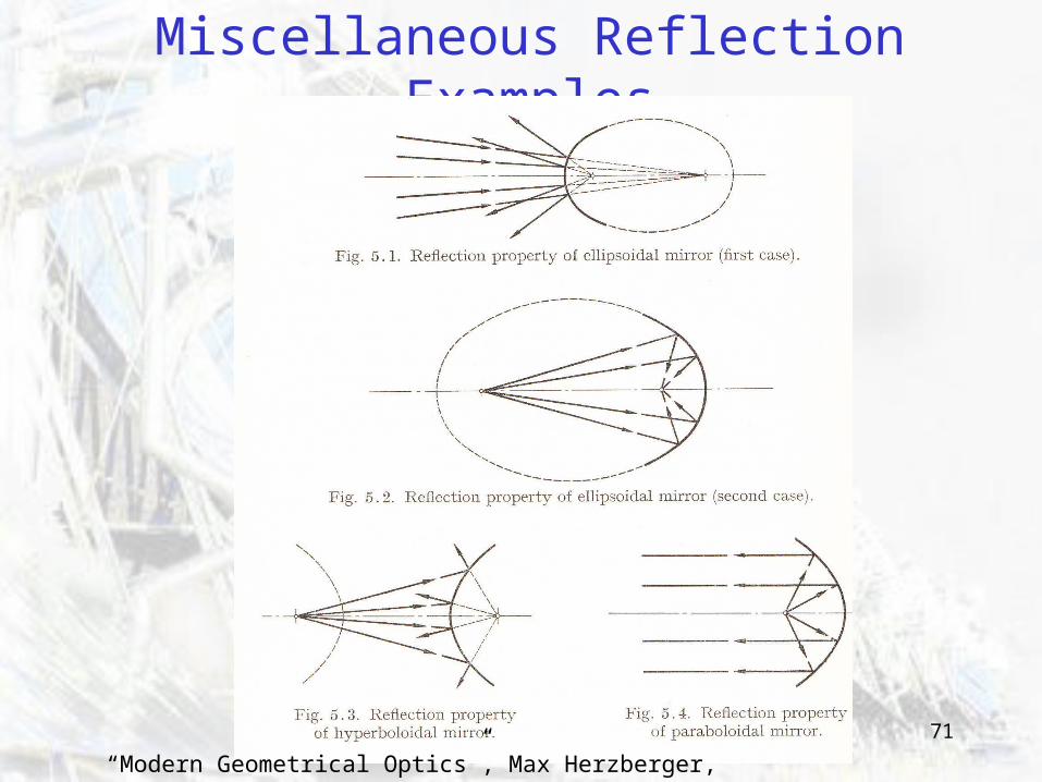
Miscellaneous Reflection Examples
“Modern Geometrical Optics”, Max Herzberger, 1958
72
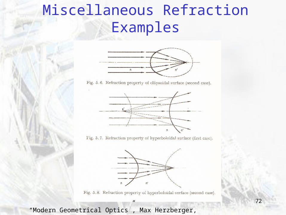
Miscellaneous Refraction Examples
“Modern Geometrical Optics”, Max Herzberger, 1958
73
Edge Ray Analysis
• Edge ray analysis is used to do ray tracing by hand.
• Select rays to establish bounds: – Extreme angles– With maximum error.
74
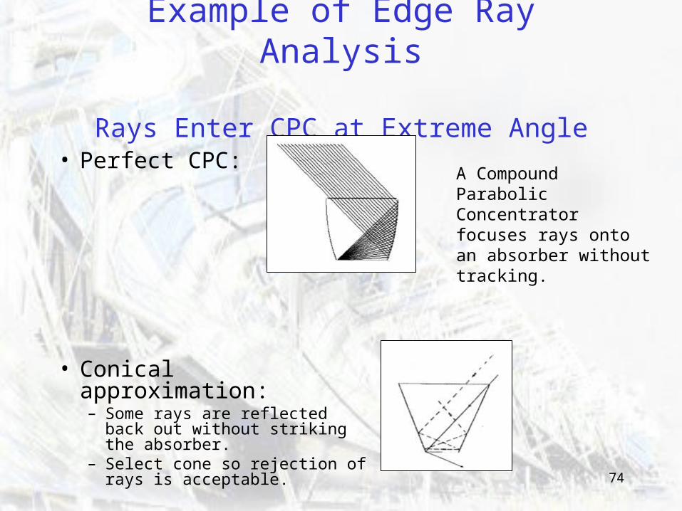
Example of Edge Ray Analysis
Rays Enter CPC at Extreme Angle
• Perfect CPC:
• Conical approximation:– Some rays are reflected back
out without striking the absorber.
– Select cone so rejection of rays is acceptable.
A Compound Parabolic Concentrator focuses rays onto an absorber without tracking.
75
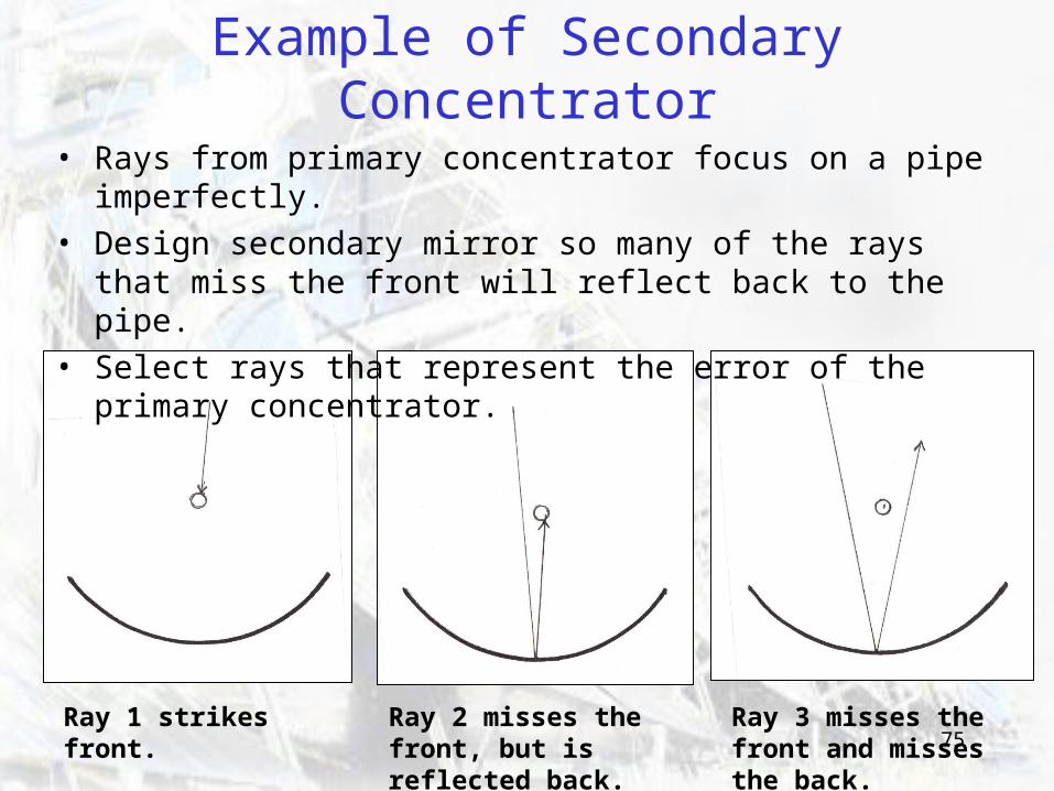
Example of Secondary Concentrator
• Rays from primary concentrator focus on a pipe imperfectly.
• Design secondary mirror so many of the rays that miss the front will reflect back to the pipe.
• Select rays that represent the error of the primary concentrator.
Ray 1 strikes front. Ray 2 misses the front, but is reflected back.
Ray 3 misses the front and misses the back.
76
Ray Tracing by Computer
• Ray tracing by hand, you are limited to selecting a small number of rays.
• Ray tracing by computer, you can send in many rays.– Can look at distribution of rays across a
surface.
77
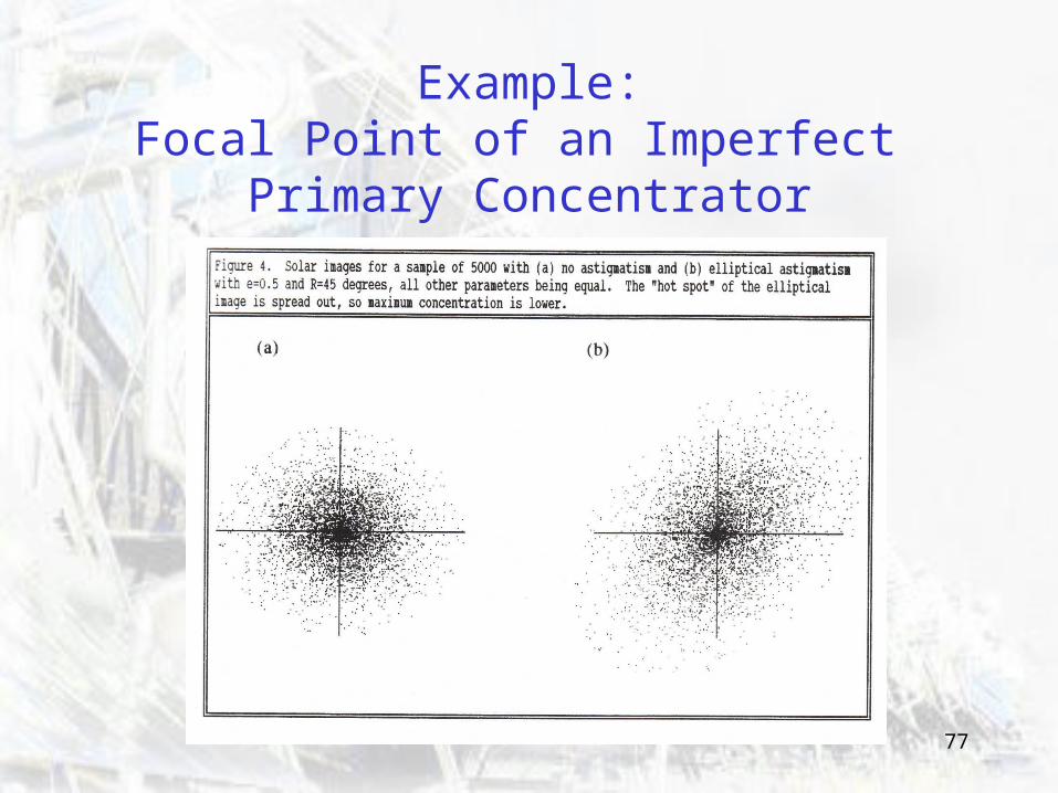
Example:Focal Point of an Imperfect
Primary Concentrator
78
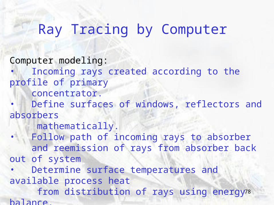
Ray Tracing by Computer
Computer modeling:• Incoming rays created according to the profile of primary concentrator.• Define surfaces of windows, reflectors and absorbers mathematically.• Follow path of incoming rays to absorber and reemission of rays from absorber back out of system• Determine surface temperatures and available process heat from distribution of rays using energy balance.
Example design goals: • Minimize reflection out of receiver• Obtain even distribution across absorber surfaces
79
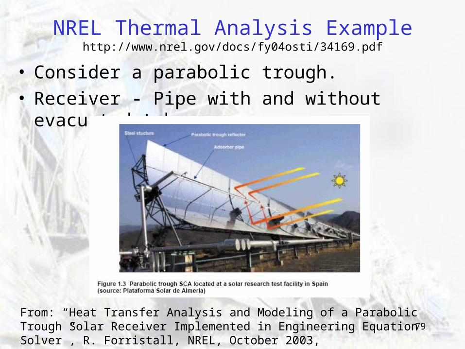
NREL Thermal Analysis Examplehttp://www.nrel.gov/docs/fy04osti/34169.pdf
• Consider a parabolic trough.• Receiver - Pipe with and without evacuated tube.
From: “Heat Transfer Analysis and Modeling of a Parabolic Trough Solar Receiver Implemented in Engineering Equation Solver”, R. Forristall, NREL, October 2003, http://www.nrel.gov/docs/fy04osti/34169.pdf
80
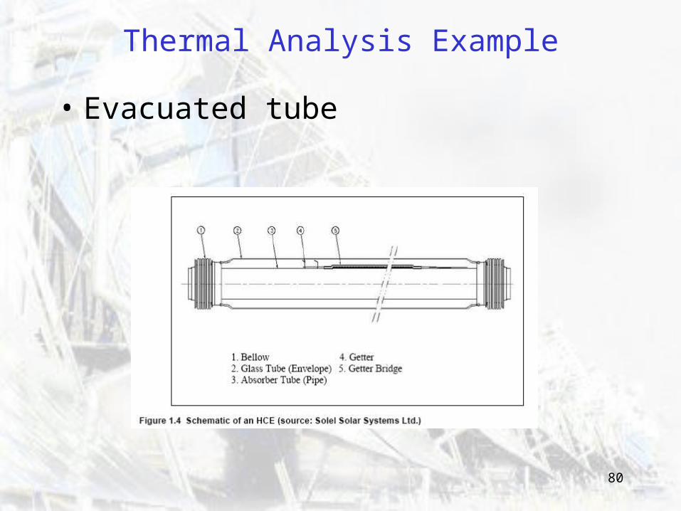
Thermal Analysis Example
• Evacuated tube
81
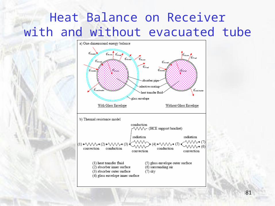
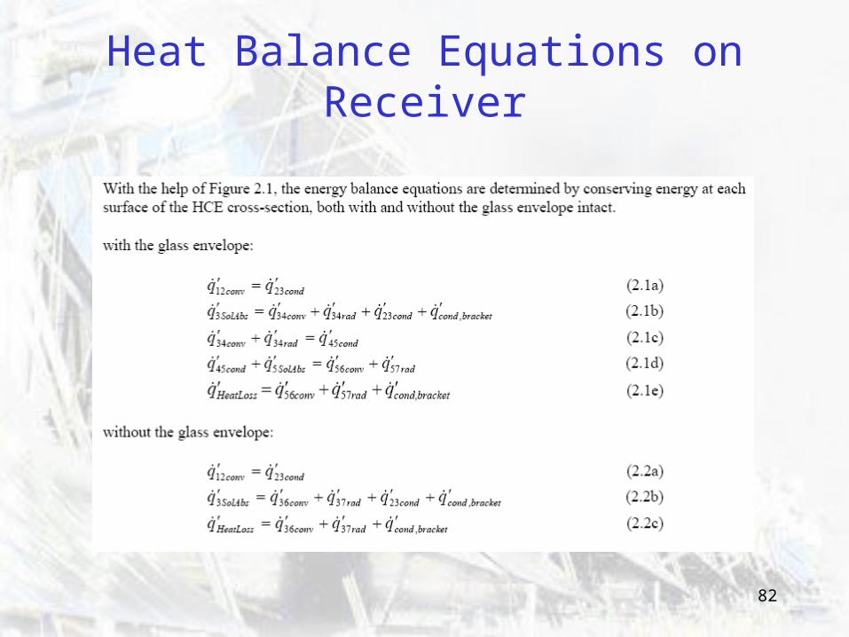
Heat Balance on Receiverwith and without evacuated tube
82
Heat Balance Equations on Receiver
83
Design
In your thermal analysis, you may be interested in considering:
• Length and cross-section of trough• Diameters of pipe and evacuated tube• Velocity of heat transfer fluid• Optical properties of the pipe, glass and trough• Weather data: Temperature, Insolation, Wind • Temperatures of surfaces and heat transfer fluid.• Energy absorbed by heat transfer fluid
Vary geometry, velocity and materials to meet your design criteria cost effectively.
84
Thermal Analysis
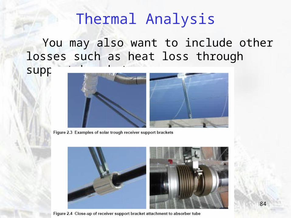
You may also want to include other losses such as heat loss through support brackets.
85
Solar News Links
The Energy Blog’s Solar Thermal page:
http://thefraserdomain.typepad.com/energy/solarthermal_/index.html
86
PARABOLIC DISH & ENGINE
SOLAR FURNACE
CENTRAL RECEIVERSOLAR FURNACE
PARABOLIC DISH
PARABOLIC TROUGH
FRESNEL REFLECTOR
LENS CONCENTRATORS
The End