Embed Size (px)
Citation preview

Crashworthiness Evaluation
Roof Strength Test Protocol (Version III)
July 2016

2016 Insurance Institute for Highway Safety Roof Strength Test Protocol (Ver. III)988 Dairy Rd, Ruckersville, VA 22968. All rights reserved. July 2016 — 1
CRASHWORTHINESS EVALUATIONROOF STRENGTH TEST PROTOCOL (VERSION III)
Supporting documents for the Insurance Institute for Highway Safety (IIHS) roof strength program areavailable from the technical protocols section of the IIHS website.
DOCUMENT REVISION HISTORY
A history of revisions to this document is provided in Appendix B.
ROOF STRENGTH TEST OVERVIEW
Roof strength evaluations consist of a quasi-static test conducted on a vehicle’s roof in a manner similarto tests used to judge compliance with Federal Motor Vehicle Safety Standard 216 (Office of the FederalRegister, 2009). The main differences between the procedure specified by the Insurance Institute forHighway Safety (IIHS) and that specified by the US federal government are that the IIHS procedure:
Specifies testing one side of a vehicle’s roof,
Does not include a headroom criterion,
Specifies testing to a given displacement instead of a given force level, and
Specifies setting the vehicle’s pitch angle during testing based on the measured on-road pitch angle.
An overall rating is assigned based on the peak strength-to-weight ratio (SWR) measured within 127 mmof plate displacement.
TEST VEHICLE SELECTION AND CURB WEIGHT MEASUREMENT
Curb weight values used for calculating SWR are based on IIHS measurements of a vehicle, not themanufacturer’s specified curb weight. Test vehicle selection criteria is provided in Appendix B.
Vehicle curb weight is measured with full fluid levels using scales manufactured by Longacre RacingProducts (Computerscales DX series 72634).
Whenever possible, the vehicle acquired for testing is the same vehicle used for the curb weightmeasurement. At times it is necessary to test a vehicle that does not meet the definition of typicallyequipped, and the curb weight measurement is applied from another vehicle that does meet the definition.In these cases, the test vehicle does not differ from the typically equipped definition in any way that mightinfluence the roof strength (e.g., a vehicle with a sunroof would not be tested if the typically equippedvehicle lacks this option).
When a given model is available in more than one body type (e.g., hatchback and sedan), the mostpopular version is tested. Counts of insurance policies from the Highway Loss Data Institute serve as themain source for determining the most popular body type. The rating only is applied to the tested bodytype. Corporate twins of the same body type and with identical roof structure are assigned the samerating based on the one test.
Once the test vehicle has been acquired, either the driver or passenger side of the vehicle is selected fortesting. For most vehicles, the test side is chosen at random. However, for roof designs that appearasymmetrical, engineering judgment is used to select the side of the roof that may result in a lower peakforce.

2016 Insurance Institute for Highway Safety Roof Strength Test Protocol (Ver. III)988 Dairy Rd, Ruckersville, VA 22968. All rights reserved. July 2016 — 2
TEST VEHICLE PREPARATION
With the vehicle on a level surface, the on-road pitch angle at the front door sill is measured on both sidesof the vehicle. Unless the vehicle manufacturer requests otherwise, roof racks and other nonstructuralitems that may be contacted during the test are left as installed from the factory. Any trim or othercomponents are removed if they interfere with supporting the vehicle along its rocker panels.
For vehicles with vertical pinch weld flanges on the bottom of the rocker panels, the vehicle supportsystem consists of one I-beam (HR A-36 W4X13) for each rocker panel. Each I-beam has a clampingsystem incorporated on the top that is tightened against the pinch weld flange to clamp the system in place(Figures 1 & 2).
When the pinch weld flange has a bend that prevents supporting the sill with one I-beam, more than one I-beam can be used on each side of the vehicle. For vehicles with no pinch weld flange, or with anonvertical flange angle that precludes clamping, mounting by another method may be necessary, such asthat described in the National Highway Traffic Safety Administration’s (2006) Laboratory Test Procedure.
Prior to testing, the front row seat back on the side being tested is reclined to prevent interaction with thecrushing roof. Rear seats are latched in their upright position. All windows are closed and doors arelocked.
Figure 1Rocker Panel Support System - Attached to Vehicle
FigureRocker Panel Support System – Detail

2016 Insurance Institute for Highway Safety Roof Strength Test Protocol (Ver. III)988 Dairy Rd, Ruckersville, VA 22968. All rights reserved. July 2016 — 3
TESTING
Roof strength evaluations are conducted on a quasi-static test system manufactured by MGA ResearchCorporation (Figure 3). The system consists of an upright assembly and attached loading head that can befixed at varying heights from the ground as well as at pitch angles ranging from -5 to +5 degrees toaccommodate testing on the driver or passenger side. The roll angle is permanently fixed at 25 degrees.Four hydraulic actuators control the movement of the platen along two linear guides. The entire system ismounted on a T-slot bed plate anchored to the floor of the test facility.
Figure 3MGA Roof Crush Test System
Two HR A-36 W10x88 I-beams are mounted on the bed plate perpendicular to the longitudinal axis of theplaten. The vehicle, with attached rocker panel support system, is placed on these beams. The vehicle isadjusted so that:
1. The longitudinal centerline of platen is within 10 mm of initial roof contact point.
2. The yaw angle of the vehicle relative to longitudinal axis of the platen is 0 ± 0.5 degrees.
3. The midpoint of the platen’s forward edge is 254 ± 10 mm forward of the most forward point of theroof (including windshield trim if it overlaps the roof) lying on the vehicle’s longitudinal centerline.

2016 Insurance Institute for Highway Safety Roof Strength Test Protocol (Ver. III)988 Dairy Rd, Ruckersville, VA 22968. All rights reserved. July 2016 — 4
4. The pitch angle of the vehicle matches the on-road angle, while also accounting for any differencebetween the platen’s pitch angle and the nominal -5 degrees. The maximum combined difference ofthe vehicle and platen pitch angles from their targets is ± 0.5 degrees. (For example, if the on-roadvehicle pitch angle is -0.2 degrees and the platen pitch angle is -5.2 degrees, the target sill angle forthe test is -0.4 ± 0.5 degrees.) If necessary to achieve this angle, shims are inserted between therocker panel supports and the W10x88 I-beams attached to the bed plate.
Once the vehicle is positioned correctly, the rocker panel supports are clamped to the two perpendicular I-beams, and the beams are marked to allow confirmation that the vehicle position is maintained during thetest. For body-on-frame vehicles, the frame is supported to prevent the weight of the chassis fromstressing the body at the body mounts.
The roof is crushed to a minimum displacement of 127 mm at a nominal rate of 5 mm/second. Some testsare conducted to a greater displacement to collect additional strength data for research purposes. Forcedata are recorded from five load cells (Interface Inc. model 1220) attached to the loading platen.Displacement data are recorded from four linear variable displacement transducers (LVDTs) (MTSTemposonics model GH) integrated into the hydraulic actuators. Figure 4 shows the locations of the loadcells and LVDTs on the loading platen.
Force and displacement data are collected with a National Instruments USB-6210 data acquisition systemand reported at 100 Hz. These data are based on a sampling rate of 2,000 Hz, with every 20 points beingaveraged to produce the output data at 100 Hz.
The displacement-time histories from the LVDTs are compared to verify that the platen’s roll angle andpitch angle (relative to the vehicle’s on-road pitch) were maintained at 25 ± 0.5 degrees and -5 ± 0.5degrees, respectively.
72 in.
6 in.
6.5 in.30 in.
3.5 in.
Load cellLVDT
Figure 4Position of Load Cells and LVDTs on Loading Platen

2016 Insurance Institute for Highway Safety Roof Strength Test Protocol (Ver. III)988 Dairy Rd, Ruckersville, VA 22968. All rights reserved. July 2016 — 5
The precrash and postcrash conditions of each test vehicle are documented with still photographs. Theposition of the vehicle in the test fixture also is recorded. Motion picture photography is made of the testwith real-time video cameras.
CALCULATION OF SWR RATING
Force and displacement data are recorded for 5 seconds prior to each test, while the test system holds theloading platen at initial roof contact. The data recorded from 1 to 4 seconds of this hold time areaveraged for each channel to produce a measurement offset that is subtracted from the data recordedduring the crushing of the roof. After removing the offset for each channel, the force-displacement curveis plotted using the summed output from the five load cells and the average displacement from the fourLVDTs.
The maximum force prior to 127 mm of platen displacement is divided by the measured curb weight toobtain the SWR. Both force and curb weight are rounded to the nearest pound prior to performing thecalculation, and the resulting SWR is rounded to the nearest one-hundredth of a unit. Displacement isrounded to the nearest 0.1 mm. (The maximum displacement where the load can be used for the vehiclerating is 126.9 mm.) The vehicle’s rating is assigned based on the boundaries listed in Table 1.
Table 1Roof Strength Rating Boundaries
SWR Rating≥4.00 Good≥3.25 to <4.00 Acceptable≥2.50 to <3.25 Marginal<2.50 Poor
All trim levels sharing the tested vehicle’s body type and roof structure are assigned the same rating as thetypically equipped trim level, provided their curb weights do not exceed 110 percent of the selectedvehicle’s weight. Based on published curb weights from multiple sources, any trim levels that mayexceed this weight are identified and weighed. If the weight does exceed 110 percent of the weight of theselected vehicle, a unique SWR is calculated for that trim level. If this SWR results in a lower rating,both ratings are reported for the model, with a split according to trim level. If a trim level weighs morethan 110 percent of the typically equipped model, but the lower SWR does not fall in a lower rating band,only the original SWR and rating are reported for the model.
REFERENCES
National Highway Traffic Safety Administration. 2006. Laboratory Test Procedure for FMVSS 216 RoofCrush Resistance. Report no.TP-216-05. Washington, DC: US Department of Transportation.
Office of the Federal Register. 2009. Federal Register, vol. 74, no. 90, pp. 22348-22393. NationalHighway Traffic Safety Administration – Final Rule. Docket no. NHTSA-2009-0093; 49 CFR Parts 571and 585 – Federal Motor Vehicle Safety Standards, Roof Crush Resistance and Phase-In ReportingRequirements. Washington, DC: National Archives and Records Administration.
2016 Insurance Institute for Highway Safety Roof Strength Test Protocol (Ver. III)988 Dairy Rd, Ruckersville, VA 22968. All rights reserved. July 2016 — A-1
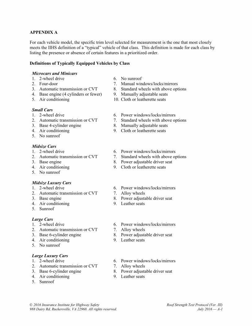
APPENDIX A
For each vehicle model, the specific trim level selected for measurement is the one that most closelymeets the IIHS definition of a “typical” vehicle of that class. This definition is made for each class bylisting the presence or absence of certain features in a prioritized order.
Definitions of Typically Equipped Vehicles by Class
Microcars and Minicars1. 2-wheel drive2. Four-door3. Automatic transmission or CVT4. Base engine (4 cylinders or fewer)5. Air conditioning
6. No sunroof7. Manual windows/locks/mirrors8. Standard wheels with above options9. Manually adjustable seats10. Cloth or leatherette seats
Small Cars1. 2-wheel drive2. Automatic transmission or CVT3. Base 4-cylinder engine4. Air conditioning5. No sunroof
6. Power windows/locks/mirrors7. Standard wheels with above options8. Manually adjustable seats9. Cloth or leatherette seats
Midsize Cars1. 2-wheel drive2. Automatic transmission or CVT3. Base engine4. Air conditioning5. No sunroof
6. Power windows/locks/mirrors7. Standard wheels with above options8. Power adjustable driver seat9. Cloth or leatherette seats
Midsize Luxury Cars1. 2-wheel drive2. Automatic transmission or CVT3. Base engine4. Air conditioning5. Sunroof
6. Power windows/locks/mirrors7. Alloy wheels8. Power adjustable driver seat9. Leather seats
Large Cars1. 2-wheel drive2. Automatic transmission or CVT3. Base 6-cylinder engine4. Air conditioning5. No sunroof
6. Power windows/locks/mirrors7. Alloy wheels8. Power adjustable driver seat9. Leather seats
Large Luxury Cars1. 2-wheel drive2. Automatic transmission or CVT3. Base 6-cylinder engine4. Air conditioning5. Sunroof
6. Power windows/locks/mirrors7. Alloy wheels8. Power adjustable driver seat9. Leather seats

2016 Insurance Institute for Highway Safety Roof Strength Test Protocol (Ver. III)988 Dairy Rd, Ruckersville, VA 22968. All rights reserved. July 2016 — A-2
Small SUVs1. 4-wheel drive2. Automatic transmission3. Base 4-cylinder engine4. Air conditioning5. No sunroof6. Two rows of seats
7. Power windows/locks8. Standard wheels with above options9. No longitudinal roof racks10. Manually adjustable front seats11. Cloth or leatherette seats
Midsize SUVs1. 4-wheel drive2. Automatic transmission3. Base engine4. Air conditioning5. No sunroof
6. Third row seat7. Power windows/locks/mirrors8. Standard wheels with above options9. Longitudinal roof racks10. Power adjustable driver seat11. Cloth or leatherette seats
Midsize Luxury SUVs1. 4-wheel drive2. Automatic transmission3. Base engine4. Air conditioning5. Sunroof
6. Two rows of seats7. Power windows/locks/mirrors8. Alloy wheels9. Longitudinal roof racks10. Power adjustable front seats11. Leather seats
Large SUVs1. 4-wheel drive2. Automatic transmission3. Base engine (6 or 8 cylinder)4. Air conditioning5. Sunroof6. Third row seat
7. Power windows/locks/mirrors8. Alloy wheels9. Longitudinal roof racks10. Power adjustable front seats11. Leather seats
Minivans1. 2-wheel drive2. Automatic transmission or CVT3. Base 6-cylinder engine4. Air conditioning5. No sunroof6. Power windows/locks/mirrors
7. Power sliding doors (both sides)8. Power tailgate9. Alloy wheels10. Power adjustable driver seat11. Cloth seats
Small and Large Pickups1. 2-wheel drive2. Crew cab3. Short bed (nominal 6 foot)4. Automatic transmission5. Base V6 (small trucks) or
Base V8 (large trucks)
6. Air conditioning7. No sunroof8. Power windows/locks/mirrors9. Standard wheels with above options10. Manually adjustable seats11. Cloth seats

2016 Insurance Institute for Highway Safety Roof Strength Test Protocol (Ver. III)988 Dairy Rd, Ruckersville, VA 22968. All rights reserved. July 2016 — B-1
APPENDIX B
Document Revision History
Revisions to Version III of the protocol compared to Version II: Test vehicle selection criteria was updated to better cover current trends in vehicle sales and
production. Roof rails will not be removed prior to testing unless requested by manufacturer. The vehicle support system (pinch weld clamping) used for testing has been updated.
Revisions to Version II of the protocol compared with Version I: Availability of standard or alloy wheels has been given higher priority in the list of definitions of
typically equipped vehicles relative to seat adjustment type (power vs. manual) and seating surfacematerial.
Availability of antilock braking system (ABS) and electronic stability control (ESC) has beenremoved from the definitions of typically equipped vehicles because these features now are standardequipment on all passenger vehicles.