Embed Size (px)
Citation preview
LANXESS Deutschland GmbHSemi-Crystalline ProductsProduct & Appllication DevelopmentBuilding B 207D-51369 Leverkusen
Germany
XReprint from VDI-Report No. 4261 (2004), pages 25 - 45© VDI Verlag GmbH, Düsseldorf 2004
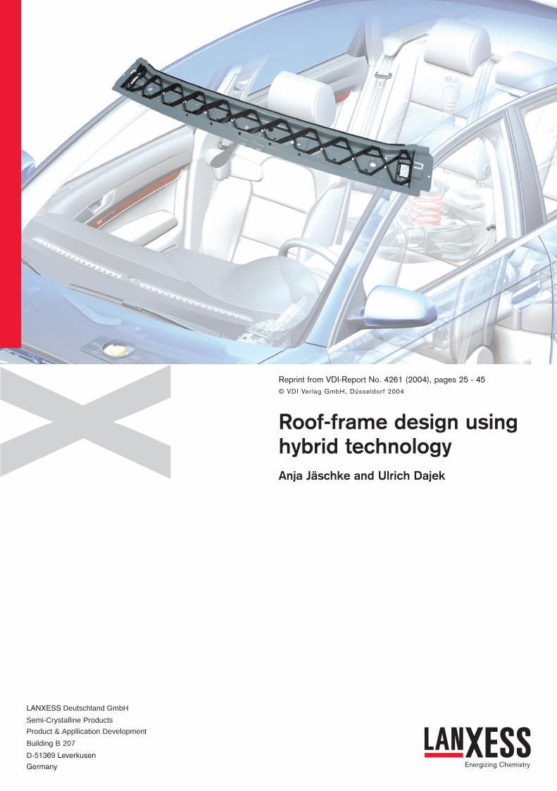
Roof-frame design usinghybrid technologyAnja Jäschke and Ulrich Dajek
VDI_Titel engl. 5.0 05.08.2004 14:40 Uhr Seite 1
General information about hybrid technology
Defi nition of hybrid technology
The term 'hybrid technology' is being used increasingly
these days for certain technical applications. One application
of hybrid technology, deriving from a patent of Bayer AG,
Leverkusen, takes the form of a composite of the two materials
of plastic and metal and it is with this that the present
contribution will be concerned.
The word 'hybrid' is of Latin origin and is defi ned by the
Oxford English Dictionary as "the offspring of two animals
or plants of different species, or (less strictly) varieties".
Accordingly, the term 'hybrid technology' implicitly claims that
different technologies are used alongside each other and must
work with each other.
As has already been stated, in this paper we take hybrid
technology to relate to a composite of the two materials,
plastic and metal, which can be produced using the injection
moulding method (cf. Fig. 1). The resulting hybrid structure
combines the advantages of the two materials together with
the corresponding processing and machining techniques. [1]
The hybrid construction basically consists of a thin-walled
sheet steel structure forming a composite with suitably
designed plastic sections (see also Fig. 1) which give the metal
the mechanical properties it requires.
Manufacture of hybrid components
Not only the specifi c properties of the materials used but
also the two economically effi cient processing methods
of metal deepdrawing and injection moulding supplement
each other with the result that reliable, reproducible and
close manufacturing tolerances are possible. This means that
complex, ready-to-assemble components can be manufactured
in just a few operations.
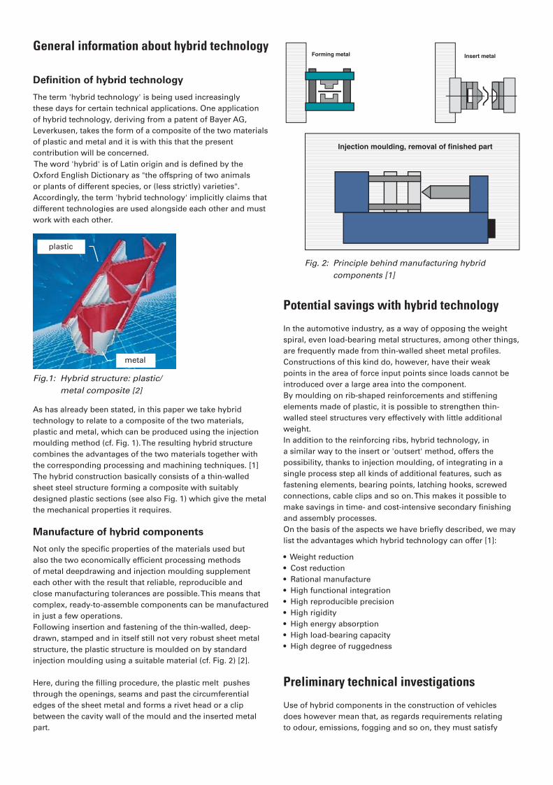
Following insertion and fastening of the thin-walled, deep-
drawn, stamped and in itself still not very robust sheet metal
structure, the plastic structure is moulded on by standard
injection moulding using a suitable material (cf. Fig. 2) [2].
Here, during the fi lling procedure, the plastic melt pushes
through the openings, seams and past the circumferential
edges of the sheet metal and forms a rivet head or a clip
between the cavity wall of the mould and the inserted metal
part.
Potential savings with hybrid technology
In the automotive industry, as a way of opposing the weight
spiral, even load-bearing metal structures, among other things,
are frequently made from thin-walled sheet metal profi les.
Constructions of this kind do, however, have their weak
points in the area of force input points since loads cannot be
introduced over a large area into the component.
By moulding on rib-shaped reinforcements and stiffening
elements made of plastic, it is possible to strengthen thin-
walled steel structures very effectively with little additional
weight.
In addition to the reinforcing ribs, hybrid technology, in
a similar way to the insert or 'outsert' method, offers the
possibility, thanks to injection moulding, of integrating in a
single process step all kinds of additional features, such as
fastening elements, bearing points, latching hooks, screwed
connections, cable clips and so on. This makes it possible to
make savings in time- and cost-intensive secondary fi nishing
and assembly processes.
On the basis of the aspects we have briefl y described, we may
list the advantages which hybrid technology can offer [1]:
• Weight reduction
• Cost reduction
• Rational manufacture
• High functional integration
• High reproducible precision
• High rigidity
• High energy absorption
• High load-bearing capacity
• High degree of ruggedness
Preliminary technical investigations
Use of hybrid components in the construction of vehicles
does however mean that, as regards requirements relating
to odour, emissions, fogging and so on, they must satisfy
Forming metal Insert metal
Injection moulding, removal of finished part
Fig. 2: Principle behind manufacturing hybrid
components [1]
Kunststoff
Metall
Fig.1: Hybrid structure: plastic/
metal composite [2]
plastic
metal
ES 8_jäschke.indd 8 05.08.2004, 14:34:25
the same requirements within the process chain and as
regards corrosion protection as must comparable all-metal
components.
In order to be able to determine the load-bearing capacity of a
hybrid profi le in comparison with purely metal designs, Bayer
and the University of Erlangen built an injection mould for
ribbed, three-dimensional hybrid structures (U-shaped hybrid
beams). Extensive preliminary technical investigations were
carried out on these test supports.
Fogging, emissions and odour
Fogging, emissions and odour are requirements applicable to
materials or components in the vehicle interior and luggage
compartment as well as to parts which come into contact with
the air fl owing into the vehicle interior. At Audi the standard
VW 501 80 applies. According to this, with new designs the
only materials which may be used (in this case the plastic of
the hybrid component) are those which remain below the limit
values specifi ed in the standard [3].
The behaviour as regards fogging, emissions and odour which
must satisfy the values defi ned in the standards and inspection
specifi cations before any use is permitted in the vehicle
interior, was examined on the basis of the plastics Durethan
BKV 130 H2.0 and Durethan BKV 30 H2.0.
As regards the aspects of emissions and odour, approval could
not be given for Durethan BKV 130. According to the results,
the responsibility for the poorer evaluation of the odour in the
case of the Durethan BKV 130 lies with the rubber components.
The consequence of the test is that the selection of materials
for hybrid bodyshell parts is restricted to Durethan BKV 30
which was then used in all subsequent tests.
Process-determined requirements
In what follows, from the stations in the process chain of
vehicle production, we shall ascertain what are the process-
determined requirements applicable to hybrid components.
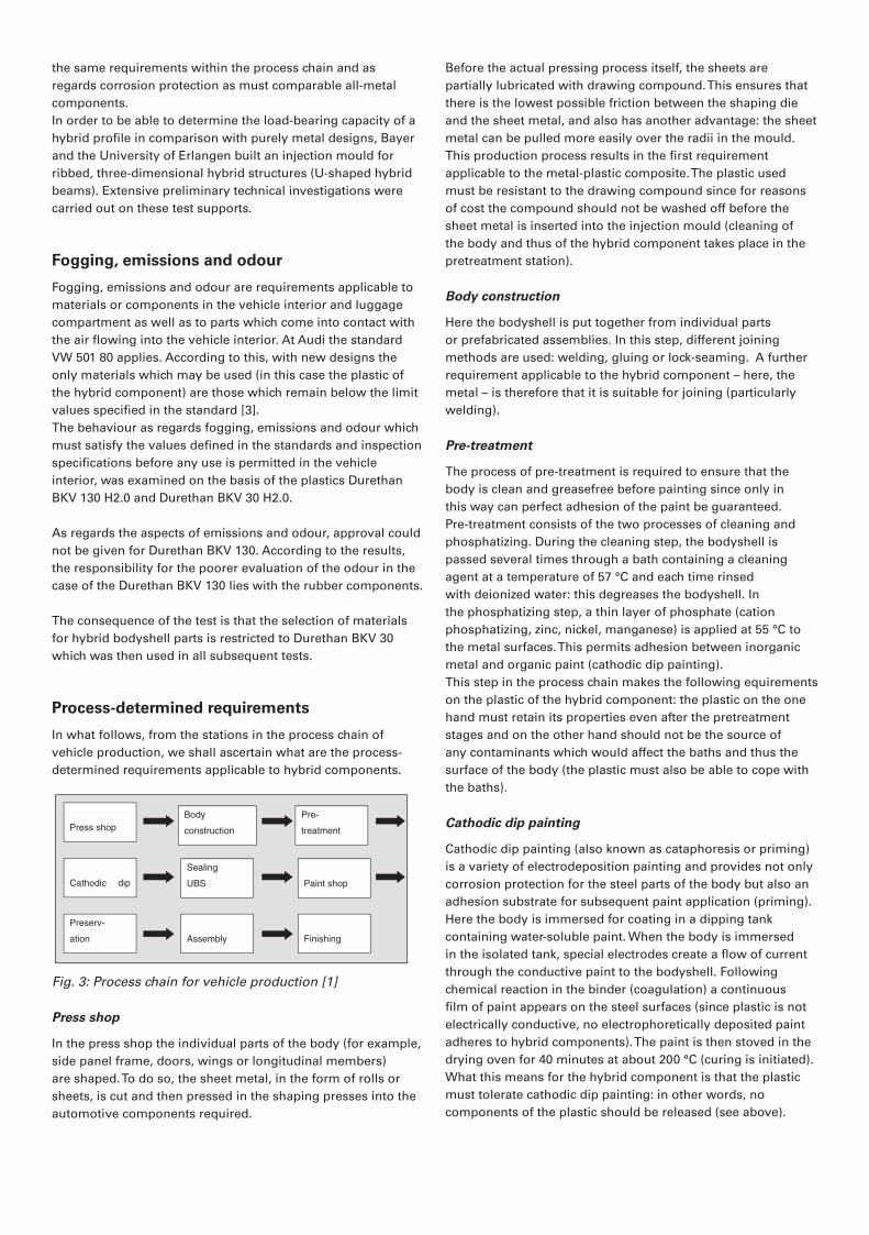
Fig. 3: Process chain for vehicle production [1]
Press shop
In the press shop the individual parts of the body (for example,
side panel frame, doors, wings or longitudinal members)
are shaped. To do so, the sheet metal, in the form of rolls or
sheets, is cut and then pressed in the shaping presses into the
automotive components required.
Before the actual pressing process itself, the sheets are
partially lubricated with drawing compound. This ensures that
there is the lowest possible friction between the shaping die
and the sheet metal, and also has another advantage: the sheet
metal can be pulled more easily over the radii in the mould.
This production process results in the fi rst requirement
applicable to the metal-plastic composite. The plastic used
must be resistant to the drawing compound since for reasons
of cost the compound should not be washed off before the
sheet metal is inserted into the injection mould (cleaning of
the body and thus of the hybrid component takes place in the
pretreatment station).
Body construction
Here the bodyshell is put together from individual parts
or prefabricated assemblies. In this step, different joining
methods are used: welding, gluing or lock-seaming. A further
requirement applicable to the hybrid component – here, the
metal – is therefore that it is suitable for joining (particularly
welding).
Pre-treatment
The process of pre-treatment is required to ensure that the
body is clean and greasefree before painting since only in
this way can perfect adhesion of the paint be guaranteed.
Pre-treatment consists of the two processes of cleaning and
phosphatizing. During the cleaning step, the bodyshell is
passed several times through a bath containing a cleaning
agent at a temperature of 57 °C and each time rinsed
with deionized water: this degreases the bodyshell. In
the phosphatizing step, a thin layer of phosphate (cation
phosphatizing, zinc, nickel, manganese) is applied at 55 °C to
the metal surfaces. This permits adhesion between inorganic
metal and organic paint (cathodic dip painting).
This step in the process chain makes the following equirements
on the plastic of the hybrid component: the plastic on the one
hand must retain its properties even after the pretreatment
stages and on the other hand should not be the source of
any contaminants which would affect the baths and thus the
surface of the body (the plastic must also be able to cope with
the baths).
Cathodic dip painting
Cathodic dip painting (also known as cataphoresis or priming)
is a variety of electrodeposition painting and provides not only
corrosion protection for the steel parts of the body but also an
adhesion substrate for subsequent paint application (priming).
Here the body is immersed for coating in a dipping tank
containing water-soluble paint. When the body is immersed
in the isolated tank, special electrodes create a fl ow of current
through the conductive paint to the bodyshell. Following
chemical reaction in the binder (coagulation) a continuous
fi lm of paint appears on the steel surfaces (since plastic is not
electrically conductive, no electrophoretically deposited paint
adheres to hybrid components). The paint is then stoved in the
drying oven for 40 minutes at about 200 °C (curing is initiated).
What this means for the hybrid component is that the plastic
must tolerate cathodic dip painting: in other words, no
components of the plastic should be released (see above).
Press shop
Body
construction
Pre-
treatment
Cathodic dip
Sealing
UBS Paint shop
Preserv-
ation Assembly Finishing
ES 8_jäschke.indd 9 05.08.2004, 14:34:26
Furthermore, it must retain its range of properties even after
the cathodic dip painting tank and also the exposure to higher
temperatures.
Paint shop
The plastic should not
be the source of any
undesirable potential
for problems (such as,
for example, craters
or wetting defects).
These arise when, due
to their surface tension,
substances prevent the
paint from wetting the
surface adequately.
Responsible for paint
fl aws of this kind, such
as may be seen in
Fig. 4, are primarily greases, oils, separating agents and also
silicones which under certain circumstances can emerge from
the plastic and cause contamination.
What this means for the hybrid component is that the plastic
must be paint-tolerant: in other words, no components of the
plastic should be released (see above).
Summary of results
In collaboration with Bayer – material manufacturer, patent-
holder and source of knowledge in the fi eld of hybrid
technology – we were able to demonstrate that the material
Durethan BKV 30 H2.0 was resistant to the media used (no
contamination of the baths) and that the properties of the
plastic were retained after passing through the process.
Corrosion behaviour
One important precondition for the use of hybrid technology
in body construction is that that Audi‘s corrosion requirements
are satisfi ed. Here the car is subdivided into various
'corrosion sections' which include dry sections (exposed to
little corrosion), moist sections (subject to a minor amount
of corrosion) and wet sections (subject to a higher degree of
corrosion). For each of these sections, different requirements
apply with regard to corrosion properties, and the result is that
a 12-year guarantee against corrosive penetration of the body
can be given.
By passive corrosion protection is meant the application of a
layer of a protective material which hinders attack by corrosive
media. Here the coating thicknesses may range from 10-3 to
several millimetres. At Audi the entire body (in other words, all
metal components) is protected against corrosion by a primer
coat applied by cathodic dip painting (cataphoretic paint) [1].
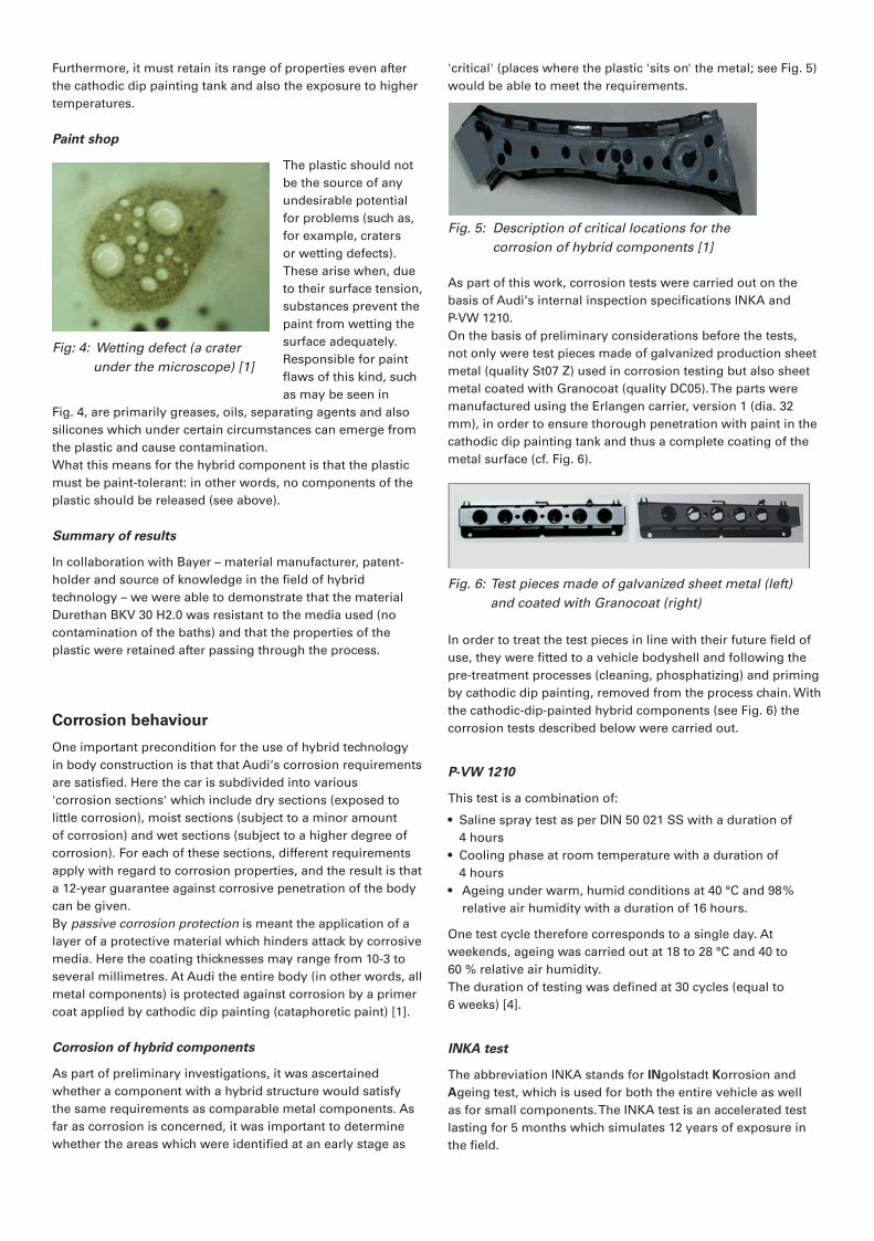
Corrosion of hybrid components
As part of preliminary investigations, it was ascertained
whether a component with a hybrid structure would satisfy
the same requirements as comparable metal components. As
far as corrosion is concerned, it was important to determine
whether the areas which were identifi ed at an early stage as
'critical' (places where the plastic 'sits on' the metal; see Fig. 5)
would be able to meet the requirements.
Fig. 5: Description of critical locations for the
corrosion of hybrid components [1]
As part of this work, corrosion tests were carried out on the
basis of Audi‘s internal inspection specifi cations INKA and
P-VW 1210.
On the basis of preliminary considerations before the tests,
not only were test pieces made of galvanized production sheet
metal (quality St07 Z) used in corrosion testing but also sheet
metal coated with Granocoat (quality DC05). The parts were
manufactured using the Erlangen carrier, version 1 (dia. 32
mm), in order to ensure thorough penetration with paint in the
cathodic dip painting tank and thus a complete coating of the
metal surface (cf. Fig. 6).
Fig. 6: Test pieces made of galvanized sheet metal (left)
and coated with Granocoat (right)
In order to treat the test pieces in line with their future fi eld of
use, they were fi tted to a vehicle bodyshell and following the
pre-treatment processes (cleaning, phosphatizing) and priming
by cathodic dip painting, removed from the process chain. With
the cathodic-dip-painted hybrid components (see Fig. 6) the
corrosion tests described below were carried out.
P-VW 1210
This test is a combination of:
• Saline spray test as per DIN 50 021 SS with a duration of
4 hours
• Cooling phase at room temperature with a duration of
4 hours
• Ageing under warm, humid conditions at 40 °C and 98%
relative air humidity with a duration of 16 hours.
One test cycle therefore corresponds to a single day. At
weekends, ageing was carried out at 18 to 28 °C and 40 to
60 % relative air humidity.
The duration of testing was defi ned at 30 cycles (equal to
6 weeks) [4].
INKA test
The abbreviation INKA stands for INgolstadt Korrosion and
Ageing test, which is used for both the entire vehicle as well
as for small components. The INKA test is an accelerated test
lasting for 5 months which simulates 12 years of exposure in
the fi eld.
Fig: 4: Wetting defect (a crater
under the microscope) [1]
ES 8_jäschke.indd 10 05.08.2004, 14:34:26
With the hybrid components the following test for small parts
was carried out (one pass-through corresponds to one cycle)
[5]:
Constant humidity at T = 50 °C and 98 to 100% relative
humidity with a duration of 29.25 hours
Constant coldness at T = -5 °C and a duration of 3.5 hours
(humidity not controlled)
Saline spray mist at T = 35 °C and 100% relative humidity and a
duration of 3.5 hours
Rest phases at room temperature (due to moving between test
chambers)
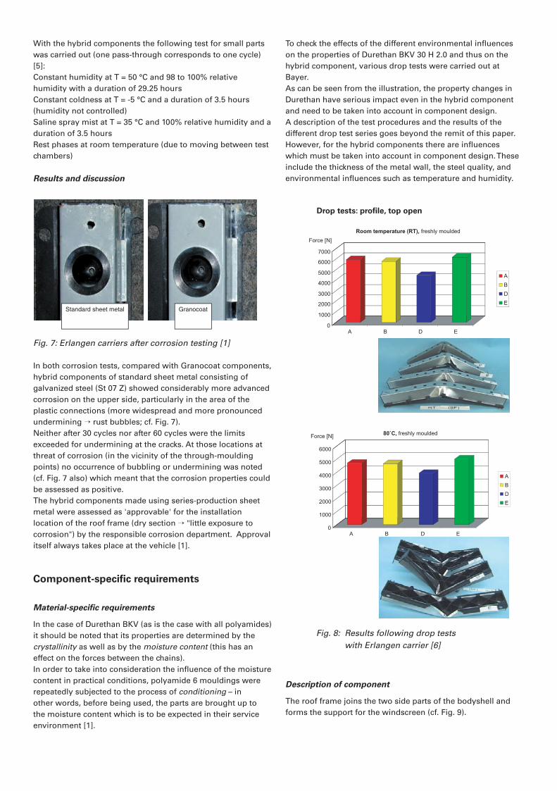
Results and discussion
Fig. 7: Erlangen carriers after corrosion testing [1]
In both corrosion tests, compared with Granocoat components,
hybrid components of standard sheet metal consisting of
galvanized steel (St 07 Z) showed considerably more advanced
corrosion on the upper side, particularly in the area of the
plastic connections (more widespread and more pronounced
undermining � rust bubbles; cf. Fig. 7).
Neither after 30 cycles nor after 60 cycles were the limits
exceeded for undermining at the cracks. At those locations at
threat of corrosion (in the vicinity of the through-moulding
points) no occurrence of bubbling or undermining was noted
(cf. Fig. 7 also) which meant that the corrosion properties could
be assessed as positive.
The hybrid components made using series-production sheet
metal were assessed as 'approvable' for the installation
location of the roof frame (dry section � "little exposure to
corrosion") by the responsible corrosion department. Approval
itself always takes place at the vehicle [1].
Component-specifi c requirements
Material-specifi c requirements
In the case of Durethan BKV (as is the case with all polyamides)
it should be noted that its properties are determined by the
crystallinity as well as by the moisture content (this has an
effect on the forces between the chains).
In order to take into consideration the infl uence of the moisture
content in practical conditions, polyamide 6 mouldings were
repeatedly subjected to the process of conditioning – in
other words, before being used, the parts are brought up to
the moisture content which is to be expected in their service
environment [1].
To check the effects of the different environmental infl uences
on the properties of Durethan BKV 30 H 2.0 and thus on the
hybrid component, various drop tests were carried out at
Bayer.
As can be seen from the illustration, the property changes in
Durethan have serious impact even in the hybrid component
and need to be taken into account in component design.
A description of the test procedures and the results of the
different drop test series goes beyond the remit of this paper.
However, for the hybrid components there are infl uences
which must be taken into account in component design. These
include the thickness of the metal wall, the steel quality, and
environmental infl uences such as temperature and humidity.
Description of component
The roof frame joins the two side parts of the bodyshell and
forms the support for the windscreen (cf. Fig. 9).
Standard sheet metal Granocoat
Drop tests: profi le, top open
0
1000
2000
3000
4000
5000
6000
7000
A B D E
A
B
D
E
�Room temperature (RT), freshly moulded
Force [N]
Fig. 8: Results following drop tests
with Erlangen carrier [6]
nach
0
1000
2000
3000
4000
5000
6000
A B D E
A
B
D
E
� 80˚C, freshly moulded Force [N]
ES 8_jäschke.indd 11 05.08.2004, 14:34:27
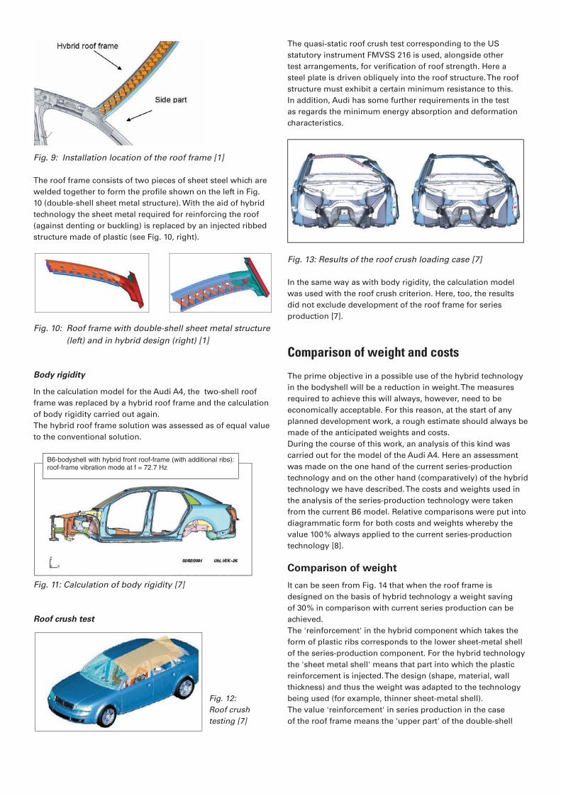
Fig. 9: Installation location of the roof frame [1]
The roof frame consists of two pieces of sheet steel which are
welded together to form the profi le shown on the left in Fig.
10 (double-shell sheet metal structure). With the aid of hybrid
technology the sheet metal required for reinforcing the roof
(against denting or buckling) is replaced by an injected ribbed
structure made of plastic (see Fig. 10, right).
Fig. 10: Roof frame with double-shell sheet metal structure
(left) and in hybrid design (right) [1]
Body rigidity
In the calculation model for the Audi A4, the two-shell roof
frame was replaced by a hybrid roof frame and the calculation
of body rigidity carried out again.
The hybrid roof frame solution was assessed as of equal value
to the conventional solution.
Fig. 11: Calculation of body rigidity [7]
Roof crush test
The quasi-static roof crush test corresponding to the US
statutory instrument FMVSS 216 is used, alongside other
test arrangements, for verifi cation of roof strength. Here a
steel plate is driven obliquely into the roof structure. The roof
structure must exhibit a certain minimum resistance to this.
In addition, Audi has some further requirements in the test
as regards the minimum energy absorption and deformation
characteristics.
Fig. 13: Results of the roof crush loading case [7]
In the same way as with body rigidity, the calculation model
was used with the roof crush criterion. Here, too, the results
did not exclude development of the roof frame for series
production [7].
Comparison of weight and costs
The prime objective in a possible use of the hybrid technology
in the bodyshell will be a reduction in weight. The measures
required to achieve this will always, however, need to be
economically acceptable. For this reason, at the start of any
planned development work, a rough estimate should always be
made of the anticipated weights and costs.
During the course of this work, an analysis of this kind was
carried out for the model of the Audi A4. Here an assessment
was made on the one hand of the current series-production
technology and on the other hand (comparatively) of the hybrid
technology we have described. The costs and weights used in
the analysis of the series-production technology were taken
from the current B6 model. Relative comparisons were put into
diagrammatic form for both costs and weights whereby the
value 100% always applied to the current series-production
technology [8].
Comparison of weight
It can be seen from Fig. 14 that when the roof frame is
designed on the basis of hybrid technology a weight saving
of 30% in comparison with current series production can be
achieved.
The 'reinforcement' in the hybrid component which takes the
form of plastic ribs corresponds to the lower sheet-metal shell
of the series-production component. For the hybrid technology
the 'sheet metal shell' means that part into which the plastic
reinforcement is injected. The design (shape, material, wall
thickness) and thus the weight was adapted to the technology
being used (for example, thinner sheet-metal shell).
The value 'reinforcement' in series production in the case
of the roof frame means the 'upper part' of the double-shell
Fig. 12:
Roof crush
testing [7]
B6-bodyshell with hybrid front roof-frame (with additional ribs):roof-frame vibration mode at f = 72.7 Hz
ES 8_jäschke.indd 12 05.08.2004, 14:34:27
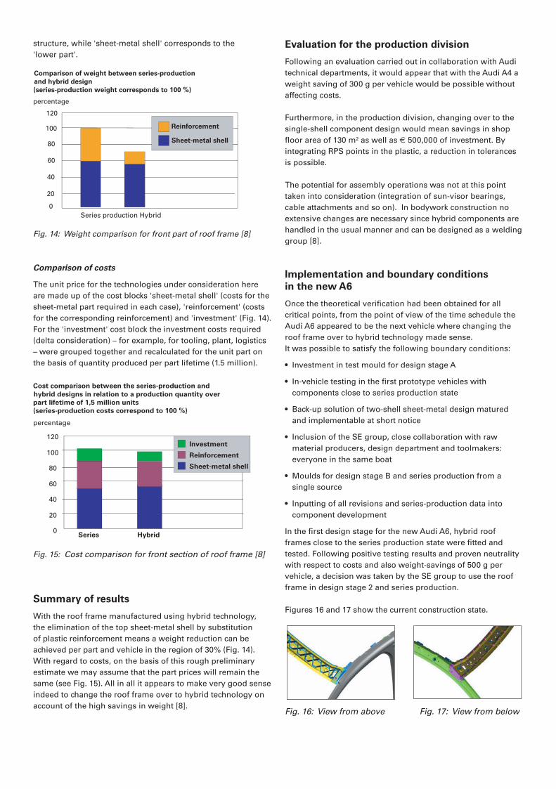
structure, while 'sheet-metal shell' corresponds to the
'lower part'.
Fig. 14: Weight comparison for front part of roof frame [8]
Comparison of costs
The unit price for the technologies under consideration here
are made up of the cost blocks 'sheet-metal shell' (costs for the
sheet-metal part required in each case), 'reinforcement' (costs
for the corresponding reinforcement) and 'investment' (Fig. 14).
For the 'investment' cost block the investment costs required
(delta consideration) – for example, for tooling, plant, logistics
– were grouped together and recalculated for the unit part on
the basis of quantity produced per part lifetime (1.5 million).
Fig. 15: Cost comparison for front section of roof frame [8]
Summary of results
With the roof frame manufactured using hybrid technology,
the elimination of the top sheet-metal shell by substitution
of plastic reinforcement means a weight reduction can be
achieved per part and vehicle in the region of 30% (Fig. 14).
With regard to costs, on the basis of this rough preliminary
estimate we may assume that the part prices will remain the
same (see Fig. 15). All in all it appears to make very good sense
indeed to change the roof frame over to hybrid technology on
account of the high savings in weight [8].
Evaluation for the production division
Following an evaluation carried out in collaboration with Audi
technical departments, it would appear that with the Audi A4 a
weight saving of 300 g per vehicle would be possible without
affecting costs.
Furthermore, in the production division, changing over to the
single-shell component design would mean savings in shop
fl oor area of 130 m² as well as € 500,000 of investment. By
integrating RPS points in the plastic, a reduction in tolerances
is possible.
The potential for assembly operations was not at this point
taken into consideration (integration of sun-visor bearings,
cable attachments and so on). In bodywork construction no
extensive changes are necessary since hybrid components are
handled in the usual manner and can be designed as a welding
group [8].
Implementation and boundary conditions
in the new A6
Once the theoretical verifi cation had been obtained for all
critical points, from the point of view of the time schedule the
Audi A6 appeared to be the next vehicle where changing the
roof frame over to hybrid technology made sense.
It was possible to satisfy the following boundary conditions:
• Investment in test mould for design stage A
• In-vehicle testing in the fi rst prototype vehicles with
components close to series production state
• Back-up solution of two-shell sheet-metal design matured
and implementable at short notice
• Inclusion of the SE group, close collaboration with raw
material producers, design department and toolmakers:
everyone in the same boat
• Moulds for design stage B and series production from a
single source
• Inputting of all revisions and series-production data into
component development
In the fi rst design stage for the new Audi A6, hybrid roof
frames close to the series production state were fi tted and
tested. Following positive testing results and proven neutrality
with respect to costs and also weight-savings of 500 g per
vehicle, a decision was taken by the SE group to use the roof
frame in design stage 2 and series production.
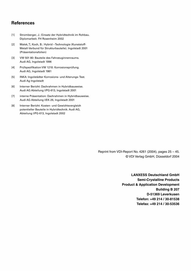
Figures 16 and 17 show the current construction state.
Fig. 16: View from above Fig. 17: View from below
0
20
40
60
80
100
120
percentage
Series Hybrid
Investment
Reinforcement
Sheet-metal shell
Cost comparison between the series-production and
hybrid designs in relation to a production quantity over
part lifetime of 1,5 million units �
(series-production costs correspond to 100 %)
Comparison of weight between series-production �
and hybrid design �
(series-production weight corresponds to 100 %)
0
20
40
60
80
100
120
percentage
Reinforcement
Sheet-metal shell
Series production Hybrid
ES 8_jäschke.indd 13 05.08.2004, 14:34:28
References
[1] Stromberger, J.: Einsatz der Hybridtechnik im Rohbau.
Diplomarbeit. FH Rosenheim 2002
[2] Malek, T.; Koch, B.: Hybrid – Technologie (Kunststoff- Metall-Verbund für Strukturbauteile). Ingolstadt 2001 (Präsentationsfolien)
[3] VW 501 80: Bauteile des Fahrzeuginnenraums. Audi AG, Ingolstadt 1996
[4] Prüfspezifikation VW 1210: Korrosionsprüfung. Audi AG, Ingolstadt 1981
[5] INKA: Ingolstädter Korrosions- und Alterungs- Test. Audi Ag Ingolstadt
[6] Interner Bericht: Dachrahmen in Hybridbauweise. Audi AG Abteilung I/PG-613, Ingolstadt 2001
[7] interne Präsentation: Dachrahmen in Hybridbauweise. Audi AG Abteilung I/EK-26, Ingolstadt 2001
[8] Interner Bericht: Kosten- und Gewichtsvergleich potentieller Bauteile in Hybridtechnik. Audi AG, Abteilung I/PG-613, Ingolstadt 2002
Reprint from VDI-Report No. 4261 (2004), pages 25 – 45.
© VDI Verlag GmbH, Düsseldorf 2004
LANXESS Deutschland GmbHSemi-Crystalline Products
Product & Application DevelopmentBuilding B 207
D-51369 LeverkusenTelefon: +49 214 / 30-81538Telefax: +49 214 / 30-53536