Embed Size (px)
Citation preview

Jasper St., Unit F, Aurora, CO 80011 T 800.624.6706 F 303.364.7796 • Newstripe.com
RollMaster™ 1000 / 3856.0917
RollMaster™ 1000 Product Manual

RollMaster™ 1000 Striper
Table of Contents
Table of Contents / 3856.0917
Precautionary Warning…........Page 1
Assembly…………………….Page 2-3
Operation ……………………Page 3-4
Helpful tips……………..……Page 4
Cleaning Procedure…………. Page 5
Troubleshooting…..………….Page 5
Parts List……………………..Page 6-7
Warranty……………………..Page 8
Thank you! For your purchase of the
Newstripe RollMaster™ 1000 Striper.
Please read over the instructions and
make sure you understand operating
procedures before using the unit.
Please check the serial number on
your unit. This Manual is for units
with serial number 1017585 and
above only. For units with serial
numbers below 1017585, please
contact Newstripe for the correct
manual.

RollMaster™ 1000 ALWAYS wear safety goggles or protective eye-wear when operating the unit!
RollMaster™ 1000 Manual / 3856.0917
PRECAUTIONARY WARNING!
• Please read and understand all operation instructions as
detailed in this manual. Failure to follow specified instructions may result in equipment damage or serious injury to person.
• Use only in well-ventilated area. • Keep away from sparks and flame – No smoking. • Wear appropriate personal protective equipment. • Always consult your Facility Safety and/or Personnel
Department for specified safety protocols prior to operating this equipment.
• Paint and all foreign matter should be kept away from the pump and trough. It is especially important that pump rollers always be clean and greased with every use.
• NEVER use fuels to clean the equipment. • DO NOT use brushes with metal bristles or any metal
object to clean any part of the RollMaster™ 1000. • The Paint Can Tube (attached to paint hose) and Mandrel
Tube (in Roller Assembly), Mandrel, and Knurled Nuts are
permanent parts of the machine. NOTE: These parts must
be cleaned after every use and are not supplied with the
Roller Hose Replacement Kits.
Page 1 of 8

RollMaster™ 1000 ALWAYS wear safety goggles or protective eye-wear when operating the unit!
1700 Jasper St. Unit F, Aurora, CO 80011 T 800.624.6706 F 303.364.7796 • Newstripe.com
RollMaster™ 1000 Manual / 3856.0917
Assembly
1. Remove the chassis and handle assembly from the box (Pic 2). 2. Rotate the folding handle upright so that the holes are aligned with the corresponding holes in the chassis. Be
careful not to damage the control cable (Pic3). 3. Fasten the Handle to the chassis with the provided Wing Nuts to the outside of the Handle (Pic3). 4. Rotate the top section of the Handle upward to the unfolded position and then tighten the Wing Knobs. 5. Pull up on the Cable Adjuster with Cable and slip into slot in the chassis. (Pic 4)
Note: The Cable Adjuster should be positioned all the way into the slot with the hex nut above the plate and round adjusting nut below the plate.
6. Adjust the nuts on the Cable Adjuster for proper operation. When adjusted correctly, the Pump Rollers will spin when the Control Lever is squeezed and stop spinning when the Control Lever is released.
7. The Guide bar / Kickstand raises the Mandrel off the surface when it is in the vertical position. When lowered for striping it can also serve as a line guide (Pic 2).
8. Remove the protective film from the Regulating Discs before installing (Pic 5). 9. Place one Regulating Disc on one end of the Mandrel core (threaded area) and screw on one Knurled Nut (finger
tight). Slide the Roller Cover onto the Mandrel and install the second Regulating Disc and Knurled Nut. Tighten the nuts fully by hand. NOTE: PVC spacers will be included with your kit if you ordered 2" or 3" wide rollers. Follow the above assembly instructions, except you must add these spacers between the plastic disc and the knurled nut.
3 2
Your RollMaster™ 1000 box should include these parts:
Can hole punch
Paint can tube
Mandrel w/ Knurled nuts
Mandrel tube with “O” ring
4” Roller kit (3 pk.)
Handle hardware
4” Roller Kit
Guide bar/ Kickstand (31)
((() 33((31)extension
bracket
Wing nut (33) Quick release
pin (32) Cable adjuster (29) in correct position
Pic 2
Regulating disc Cable adjuster in correct position
Wing Nut (33)
Wing nut
Pic 3 Pic 4 Pic 5
Mandrel w/ Knurled nuts
Paint can tube
Can hole punch
Mandrel tube
Handle hardware
Guide bar/ Kickstand
Page 2 of 8

RollMaster™ 1000 ALWAYS wear safety goggles or protective eye-wear when operating the unit!
1700 Jasper St. Unit F, Aurora, CO 80011 T 800.624.6706 F 303.364.7796 • Newstripe.com
RollMaster™ 1000 Manual / 3856.0917
Assembly for Striping
1. Apply a light coat of grease to the “O” ring and the short end of the Mandrel Tube. Insert the Mandrel Tube into the
open side of the Mandrel with the "O" ring side toward the Mandrel (Pic 6). 2. Place the Mandrel with Roller Cover in the "J" hooks of the Carrier Assembly with the Mandrel Tube to the left side.
The washer attached to the Mandrel Tube will be on the inside of the "J" Yokes. The Mandrel should be able to slide up and down in the "J" Yokes freely. If necessary, bend the side plates out just enough to allow the Mandrel to move up and down freely (Pic 7).
3. Open the Trough by grasping the Thumb Grip and the Rear Wheel hub and squeezing together (it will click and lock open) (Pic 8).
4. Slide one end of Paint Hose over the Mandrel Tube and insert the hose under the Pump Rollers and inside the Trough. Squeeze the hose flat and insert it through the side of the Eye Bolt with the colored band ABOVE the Eye Bolt at the top of the Trough. Close the Trough by pulling OUT on the release button located on the Trough (Pic 9).
5. Make sure the Paint Hose is under the Pump Rollers and is not pinched by the sides of the Trough.
OPERATION
1. Punch a hole in the can lid with the provided Punch about 1 inch from the left edge. A second SMALL "vent hole" should be punched near the other hole.
2. Insert the Paint Can Tube (1) into the punched hole. 3. Attach the open end of the Paint Hose to the Paint Can Tube. 4. When you squeeze the Control Lever, the Pump Drive Wheel is brought in contact with the Rear Wheel, and
paint is pumped directly to the Roller Cover. Release the lever and pumping stops. NOTE: Only squeeze the Control Lever in forward motion. Release the lever when rolling backwards.
5. Make sure the Trough is in the closed position. 6. To prime the Roller Cover for painting, squeeze and hold the Control Lever. Tip the unit back slightly so the front
wheels are off the ground and roll the unit forward approximately 50-75 feet. You should see ‘dots’ of paint forming on the Roller Cover. This indicates that the Roller Cover is priming properly with paint.
7. Now place the unit on an existing line or cardboard and roll the unit forward and backwards with the front wheels contacting the surface until the roller is completely saturated.
“O” Ring “J” Yoke
Trough in open position Trough in closed position
Pic 6
Paint hose Thumb grip
Roller Carrier
Regulating Disc
Pic 7 Pic 8 Pic 9
Page 3 of 8
Eye Bolt
RollMaster™ 1000 ALWAYS wear safety goggles or protective eye-wear when operating the unit!
1700 Jasper St. Unit F, Aurora, CO 80011 T 800.624.6706 F 303.364.7796 • Newstripe.com
RollMaster™ 1000 Manual / 3856.0917
OPERATIONAL NOTE!
DO NOT use lacquer-based paints.
DO NOT over-thin the paint.
The Mandrel and Roller Cover should slide up and down freely in the “J” Yokes with side clearance of not more than 1/32". Proper clearance was set at the factory, but it may be necessary to spread the side plates on the Carrier Assembly to regain this clearance.
The Mandrel and Roller Cover Roller should roll freely in the “J” Yokes. If not, lightly oil the short end of the Mandrel Tube and the “O” Ring.
Most paints can be used without thinning. However, some will "flow" better and may need to be thinned for easier use.
Cooler temperatures (50-65 degrees) will also require paint thinning. Normally, no more than 4 oz. (1/2 cup) per gallon is required. Fast Dry paints are not recommended (Fast Dry paints are those that are “no pick up” in 30 minutes or less). Also, on rough surfaces thinning will improve the appearance of the line.
Paint should be at room temperature for best results.
If Roller Cover becomes oversaturated with paint, release the Control Lever for a short period of time and continue rolling forward to allow excess paint to transfer from the Roller Cover to the surface area. Squeeze the lever again when the roller cover requires additional paint. This practice, called feathering, will be required when the operator is striping a 2" or 3" line.
Releasing the lever when you are 2-3 feet from the end of the line will allow you to finish with a clean and crisp end without puddling.
HELPFUL TIPS
The Roller Cover must be saturated with paint before a solid painted line will appear on the painting surface. It is recommended that you saturate the Roller Cover as per the operation instructions.
We recommend that you use water-base traffic paints as they are easier to clean up and do not "lift" new asphalt surfaces.
Paint should be at least room temperature for proper operation. In colder climates, the flow of paint can be restricted because the paint becomes too thick. Make sure the paint is thin enough for the pump to pull the paint from the can and through the passageways of the Mandrel. If the paint is not thin enough, you will not get a solid line and the edges of your line not appear crisp.
When stopping for prolonged periods without use, cover the Mandrel and Roller Cover in plastic wrap to prevent it from drying out.
The machine works better if the operator moves at a slow constant pace for nice even edges.
Releasing the Control Lever about two feet from the end of the line creates a crisp edge without puddling.
Page 4 of 8

RollMaster™ 1000 ALWAYS wear safety goggles or protective eye-wear when operating the unit!
1700 Jasper St. Unit F, Aurora, CO 80011 T 800.624.6706 F 303.364.7796 • Newstripe.com
RollMaster™ 1000 Manual / 3856.0917
CLEANING PROCEDURE
1. When you are finished striping, open the Trough and roll forward on a dry painted line or cardboard to transfer excess paint from the Roller Cover.
2. Remove the end of the Paint Hose attached to the Paint Can Tube. Keep the hose upright to avoid dripping paint.
3. Squeeze the Paint hose through the side of the Eye Bolt and remove Paint Hose, Mandrel tube, and Mandrel with Roller Cover from the machine. NOTE: This prevents any paint coming into contact with the pumping mechanism.
4. Set the Mandrel Tube and Paint Can Tube aside for cleaning. 5. Remove one Knurled Nut and Regulating Disc from Mandrel and slide Roller Cover off. Remove second Knurled
Nut and Regulating Disc from Mandrel. Discard Roller Cover, Regulating Discs, and Paint Hose. 6. Clean Mandrel, Knurled Nuts, Mandrel Tube, and Paint Can Tube with *water or solvent for further use.
*DO NOT THROW AWAY THE MANDREL, KNURLED NUTS, PAINT CAN TUBE, OR MANDREL TUBE AS THESE ARE PERMANENT PARTS OF THE MACHINE. NOTE: Always use the solvent recommended by the paint manufacturer. DO NOT use petroleum base cleaners or thinners with water based paint. The cleaner will react with the paint, making it difficult to clean.
7. Apply a light coat of oil to all moving parts. (3 in 1 or light spray oil)
TROUBLESHOOTING GUIDE
PROBLEM REMEDY
Paint not getting to roller or too little paint getting to roller.
1. Make sure trough is closed. 2. Check paint hose for kink. If hose is kinked open Trough and rotate
hose. 3. Check Pump Drive Wheel is contacting Rear Wheel. If not adjust the
cable at the frame. 4. Check that all Pump Rollers are rotating. If not clean rollers of debris or
paint and lubricate. 5. Check to see if your paint is “Set Fast” or “Fast Dry”. These paints are
not recommended and require thinning, which may cause the paint to dry slower, or can diminish overall line quality.
Painted line is solid on one side, but “light” or skipping on the other side.
1. Check that the Roller Cover slides up and down freely in the “J” Yoke and that the Mandrel is not binding. Adjust the “J” Yokes if needed or clean debris and paint off “J” Yokes.
2. If the Mandrel and Roller Cover is “riding up” on the Mandrel Carrier sides, grease the Mandrel Tube end and “O” ring with light oil.
Painted line has heavy ridges on edges or excessive paint.
1. Make sure you are using the proper Regulating Discs. 2. Periodically release Control Lever every couple of feet during striping
to avoid the Roller Cover from becoming oversaturated.
Paint line skips across width of roller. 1. Make sure the Mandrel and Roller Cover are rolling freely. If not, grease “O” ring end of Mandrel Tube and “O” ring.
Your machine is designed to be simple and safe to operate. If you have any questions during setup, painting or cleaning, please call us! 1-800-624-6706
Page 5 of 8
RollMaster™ 1000 ALWAYS wear safety goggles or protective eye-wear when operating the unit!
1700 Jasper St. Unit F, Aurora, CO 80011 T 800.624.6706 F 303.364.7796 • Newstripe.com
RollMaster™ 1000 Manual / 3856.0917
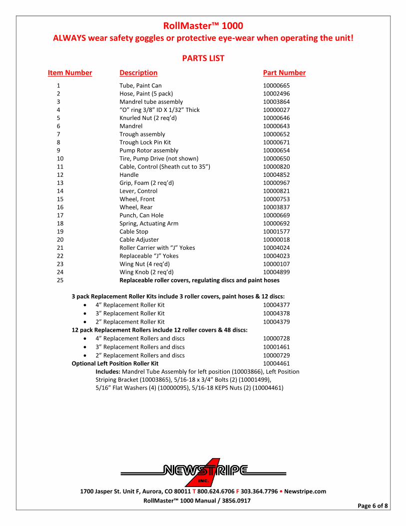
PARTS LIST
Item Number Description Part Number 1 Tube, Paint Can 10000665 2 Hose, Paint (5 pack) 10002496 3 Mandrel tube assembly 10003864 4 “O” ring 3/8” ID X 1/32” Thick 10000027 5 Knurled Nut (2 req’d) 10000646 6 Mandrel 10000643 7 Trough assembly 10000652 8 Trough Lock Pin Kit 10000671 9 Pump Rotor assembly 10000654 10 Tire, Pump Drive (not shown) 10000650 11 Cable, Control (Sheath cut to 35”) 10000820 12 Handle 10004852 13 Grip, Foam (2 req’d) 10000967 14 Lever, Control 10000821 15 Wheel, Front 10000753 16 Wheel, Rear 10003837 17 Punch, Can Hole 10000669 18 Spring, Actuating Arm 10000692 19 Cable Stop 10001577 20 Cable Adjuster 10000018 21 Roller Carrier with “J” Yokes 10004024 22 Replaceable “J” Yokes 10004023 23 Wing Nut (4 req’d) 10000107 24 Wing Knob (2 req’d) 10004899 25 Replaceable roller covers, regulating discs and paint hoses
3 pack Replacement Roller Kits include 3 roller covers, paint hoses & 12 discs:
4” Replacement Roller Kit 10004377
3” Replacement Roller Kit 10004378
2” Replacement Roller Kit 10004379 12 pack Replacement Rollers include 12 roller covers & 48 discs:
4” Replacement Rollers and discs 10000728
3” Replacement Rollers and discs 10001461
2” Replacement Rollers and discs 10000729 Optional Left Position Roller Kit 10004461 Includes: Mandrel Tube Assembly for left position (10003866), Left Position Striping Bracket (10003865), 5/16-18 x 3/4” Bolts (2) (10001499), 5/16” Flat Washers (4) (10000095), 5/16-18 KEPS Nuts (2) (10004461)
Page 6 of 8

RollMaster™ 1000 ALWAYS wear safety goggles or protective eye-wear when operating the unit!
1700 Jasper St. Unit F, Aurora, CO 80011 T 800.624.6706 F 303.364.7796 • Newstripe.com
RollMaster™ 1000 Manual / 3856.0917
PARTS PICTURES
Foam grip #13
Control lever #14
Front wheel #15
Mandrel tube #3
Paint can tube #1
Paint hose #2
Rear wheel #16
Control cable #11
Handle #12
Cable stop #19
Actuating arm spring #18
Actuating arm
Trough Lock Pin Kit #8
Thumb grip #7
Trough assembly #7
Pump rotor assembly #9
Mandrel #6
Rollers (part of #25)
Knurled Nut #5
Regulating Discs (part of #25)
Pic 10 Pic 11
Pic 12
Wing Knob #24
Pic 13
Page 7 of 8


RollMaster™ 1000 ALWAYS wear safety goggles or protective eye-wear when operating the unit!
1700 Jasper St. Unit F, Aurora, CO 80011 T 800.624.6706 F 303.364.7796 • Newstripe.com
RollMaster™ 1000 Manual / 3856.0917
THE NEWSTRIPE WARRANTY – 18 MONTH
NEWSTRIPE, INC., WARRANTS TO THE ORIGINAL PURCHASER, FOR 18 (EIGHTEEN) MONTHS AFTER
DATE OF PURCHASE, THAT THE EQUIPMENT* HEREBY SOLD SHALL BE FREE OF DEFECTS IN
MATERIALS AND WORKMANSHIP. THIS WARRANTY DOES NOT EXTEND TO ANY DAMAGE OR
MALFUNCTION RESULTING FROM MISUSE, NEGLECT, ACCIDENT, IMPROPER OPERATION, OR NORMAL
WEAR AND TEAR.
Damage incurred in shipment from Newstripe, Inc. to the customer is the total responsibility of the carrier. The
CUSTOMER MUST NOTE DAMAGES on the Bill of Lading of Trucking Company or Railroad; and Newstripe, Inc.
will furnish to the customer the cost or parts and labor. The customer can then bill the common carrier for the damages by
placing his signature on the documents.
The Newstripe, Inc. obligation under this warranty and any implied warranties is limited to replacement or repair of
defective parts of its manufacture without charge for 18 (EIGHTEEN) months from date of purchase. For service under
this warranty, buyer shall ship the defective part or parts of the equipment, transportation prepaid, to Newstripe, Inc.
together with a written description of any claimed defect and proof of purchase date of the materials being returned. Prior
to retuning any part or machine, the CUSTOMER must obtain a Return Materials Authorization number. Call 1-
800-624-6706. To review the complete guidelines for warranty and returns, please visit
www.newstripe.com/guidlinesforwarrantyandreturn.
*Gasoline engines, compressors, pumps (including airless) and Transaxles are furnished with their respective
manufacturer's warranties only. Such components are not covered by any warranty of Newstripe, Inc. Where
Newstripe elects to extend manufacturers’ warranties, the warranty shall be pro-rated as to cover 100% of the cost
to replace or repair materials and parts for the first 12 months of ownership and 60% for the remaining 6 month
period.
The responsibilities described above are the only responsibilities of Newstripe, Inc. under this written warranty or any
implied warranty, and may be exercised only within 18 (EIGHTEEN) months from the date of purchase. In no event shall
Newstripe, Inc. be liable for incidental or consequential damages and no person had any authority to bind it to any
representation or warranty, not be responsible for work done, materials furnished or repairs made by others without its'
specific written authorization.
THIS WARRANTY SHALL BE IN LIEU OF ANY AND ALL OTHER WARRANTIES, EXPRESSED OR IMPLIED,
INCLUDING ANY WARRANTIES OF MERCHANTABILITY OR FITNESS FOR A PARTICULAR PURPOSE, AND
THERE IS NO OTHER REPRESENTATION OR WARRANTY OF ANY KIND WITH RESPECT TO THE GOODS
SOLD HEREBY EXCEPT AS SET FORTH HEREIN. IT IS EXPRESSLY AGREED THAT THIS WARRANTY
SHALL BE LIMITED TO THE ADJUSTMENT, REPAIR OR REPLACEMENT OF PARTS AND THE LABOR AND
SERVICES REQUIRED THEREBY. IN NO EVENT, INCLUDING ANY CLAIM FOR NEGLIGENCE, SHALL
NEWSTRIPE, INC. BE LIABLE FOR INCIDENTAL OR CONSEQUENTIAL DAMAGES.
Sincerely,
Newstripe, Inc
Page 8 of 8