Embed Size (px)
Citation preview

4-ROLLER PUMP
SERIES 12006-ROLLER PUMP
SERIES 1500
Max. Flow Rate: ................62 gpmMax. Pressure: ..................150 psi Max. RPM: ....................1000 rpmPorts: ....1-1/2" NPT Inlet & OutletShaft: ................15/16" Dia. (Solid)Continuous Operation........100 psiIntermittent Operation........150 psi
Max. Flow Rate: ................74 gpmMax. Pressure: ..................150 psi Max. RPM: ......................800 rpmPorts: ....1-1/2" NPT Inlet & OutletShaft: ......................1" Dia. (Solid)Continuous Operation........100 psiIntermittent Operation........150 psi
5-ROLLER PUMP
Max. Flow Rate: ................45 gpmMax. Pressure:.................. 200 psi Max. RPM: ....................1000 rpmPorts:............1" NPT Inlet & Outlet............1-1/4" Hose Barb IncludedShaft: ................15/16" Dia. (Solid)Continuous Operation........100 psiIntermittent Operation........200 psi
SERIES 1700
Max. Flow Rate: ............22.4 gpmMax.Pressure: ..................200 psi Max. RPM: ......................800 rpmPorts: ........3/4" NPT Inlet & Outlet..................1" Hose Barb IncludedShaft: ................15/16" Dia. (Solid)Continuous Operation........100 psiIntermittent Operation........200 psi
7-ROLLER PUMP
SERIES 7700SERIES 75608-ROLLER PUMP
Max. Flow Rate: ................22 gpmMax. Pressure: ..................300 psi Max. RPM: ....................1000 rpmPorts: ........3/4" NPT Inlet & Outlet..................1" Hose Barb IncludedShaft: ................15/16" Dia. (Solid)Continuous Operation........100 psiIntermittent Operation........300 psi
Max. Flow Rate: ................22 gpmMax. Pressure: ..................300 psiMax. RPM: ....................1200 rpmPorts: ........3/4" NPT Inlet & Outlet..................1" Hose Barb IncludedShaft: ....................5/8" Dia. (Solid)Continuous Op. ..........100-150 psiIntermittent Operation........300 psi
Max. Flow Rate: ......9 gpm (4001)7 gpm (4101)
Max. Pressure: ..................150 psiMax. RPM:..........1800 rpm (4001)
2600 rpm (4101)Ports: ........3/4" NPT Inlet & OutletShaft: ....................5/8" Dia. (Solid)
1/2" Dia. (Hollow)Continuous Operation........100 psiIntermittent Operation........150 psi
6-ROLLER PUMP
SERIES 6500SERIES 4001 & 41014-ROLLER PUMP
iron, Ni-Resist or the new SilverCast™ body and rotor, 416stainless steel shaft, sealed factory-lubricated ballbearings, cartridge-type lip seals of Viton, Buna-N orleather, and versatile Super Rollers. (Super Rollers featurethe life of polypropylene and the chemical resistance ofnylon.) Rotation for all models is counterclockwise for easytractor PTO drive, except models 4001 and 4101 which areclockwise. Pumps are available in reverse rotation.
Hypro roller pumps are designed for agricultural andindustrial spraying and transfer of a variety fluids. Theseinclude insecticides, herbicides, emulsives, aromaticsolvents, liquid fertilizers and many other liquids. Theeconomical rotary-action roller principle requires no checkvalves while providing posit ive displacementcharacteristics with less friction and lower starting torquethan other pumps. Construction features include a cast-
ROLLER PUMPS
®®
¤¤
®®
OU
T
IN
®®O
UT
IN
®®
Installation, Operation, Repair and Parts Manual 10-04
Description
Form L-0100R

It is permissible to mount the torque arm with the chain inthe down position. To do this, mount the arm to the pump inthe reverse position. Do not use the tension spring or chain.
WARNING: Do not attach torque arm to movable linkages.
Figure 1
7. Make certain that the power source conforms to therequirements of your equipment.
8. Provide adequate protection in guarding around themoving parts such as the shaft and pulleys.
9. Disconnect power before servicing.
10. Release all pressure within the system before servicingany component.
11. Drain all liquids from the system before servicing anycomponent.
12. Check all hoses for weak or worn condition before eachuse. Make certain that all connections are tight andsecure.
13. Periodically inspect the pump and the systemcomponents. Perform routine maintenance as required(see Maintenance section).
14. Never operate a gasoline engine in an enclosed area.Be sure the area is well ventilated.
15. Use only pipe, hose and fittings rated for the maximumpsi rating of the pump.
16. Never use these pumps for pumping water or otherliquids for human or animal consumption.
1. Use a Pressure Relief Device on the discharge sideof the Pump to prevent damage from pressurebuildup when the pump discharge is blocked orotherwise closed and the power source is stillrunning.
2. WARNING: Never pump flammable or explosivefluids such as gasoline, fuel oil, kerosene, etc. Neveruse in explosive atmospheres. The Pump should beused only with liquids compatible with the Pumpcomponent materials. Failure to follow this warningcan result in personal injury and/or propertydamage and will void the product warranty.
3. Never pump acids (i.e. acid fertilizer) with SuperRollers! When pumping acidic fer til izer, Hyprorecommends only the Silver Series castings and Teflonrollers, or use one of Hypro's poly centrifugal pumps.
4. Never run the pump faster than maximumrecommended speed.
5. Never pump at pressures higher than the maximumrecommended pressure.
6. Never pump liquids at temperatures higher than therecommended maximum temperatures (140˚ F / 60˚ C).
engine for additional information. Read all safety informationbefore attempting to install or operate the pump.
This manual will cover the installation of the basic driveconfigurations available for Hypro roller pumps. Consult therecommendations of the manufacturer of your motor or
The preferred method for mounting the torque arm andpump to a tractor is with the chains going up to providesupport for the pump (see Figure 1). Attach the torque armto the pump with the long side of the arm on the inlet side ofthe pump for this type of mounting. Many tractors do nothave easy attachment points for securing the tension andtorque chains. It may be necessary to drill holes in thetractor's master shield to attach the chains.
It is also acceptable to mount an angle iron on the mastershield to attach the chains. The chains should be attached tothe tractor as close to vertical as possible to avoid a bendingforce on the pump.
1. Mount the pump and torque arm to the PTO shaft using
a Hypro series 1320, 1321 or 1323 coupler.
2. Attach the torque chain to the tractor frame with arm inhorizontal position.
3. Attach the tensioning chain to the tractor frame whileapplying tension to the spring.
2
General Safety Information
Drive Source Installation
Tractor PTO Installation

Figure 6
Figure 7
Figure 5
Push the belt midway between the pulleys, check the deflection (d) and adjust:d = 0.016 x L
==
Belt and pulley drive systems are typically used to reducepump speed. For determining proper pulley sizes, use theformula below as a guideline and use “A” or “B” sectionbelts.
MOTOR RPM FLOW (@ RATED SPEED) PUMP PULLEY DIA.PUMP RPM FLOW (DESIRED) MOTOR PULLEY DIA.
EXAMPLE: Use a 1725 RPM electric motor to drive a pump at 950 RPM.
Typically, a pulley diameter on the motor is 3.4 inches. Thepump pulley diameter can be determined from the formulaabove:
1725 PUMP PULLEY DIAMETER950 3.4 INCHES
1725 X 3.4 INCHES = 6.2 INCHES950
1. Install pulley or bushing/sheave combination (SeeFigure 5) onto pump and motor shaft. Mount pump nextto the motor making sure pulleys are lined up properly(See Figure 6 for proper pump and motor orientation).Use a straight edge as shown. Rotate to check for run-out and bent shafts.
2. Make sure belts have proper tension—belts too tight willcause bearing wear and belts too loose will causeslipping. (See Figure 7).
3. The rotation on the 4000 series roller pump is gas-engine-rotation, opposite from the standard roller pump.
3
d
L
Belt/Pulley Drive Installation

6. A strainer should be installed in the suction line. Cleanthe strainer as soon as it becomes clogged.
7. Never attach an agitator or any restriction to abypass line of a pressure relief device becausesystem damage may occur.
Figure 8
NOTE: Use only pipe, fittings, accessories, hose, etc.rated for the maximum pressure rating of the pump.
1. Select adequate size drive unit to avoid overloading.Avoid unnecessary restrictions in the line such aselbows, check valves, and all extraneous curves andbends.
2. Avoid using looped sections of tubing or pipe whichmight permit air to become trapped.
3. Use pipe joint sealant on pipe threads to assurewatertight connections.
4. Selection of the right type and size of hose is vital togood performance. Be sure to hook up the lines to theproper ports on the pump.
5. Always use a good quality suction hose (one or twobraid reinforced hose to prevent collapse) of at leastthe same diameter as the inlet port of the pump. Ifthe suction (inlet) hose is more than four feet long,then use the next larger size.
air. Make sure line strainer is free of debris. If pump does notself-prime disconnect suction hose, fill with water andreconnect to liquid source. Often a squirt of oil into the portsof the pump will seal clearances and help priming.
Care of the Pump
Hypro roller pumps are all carefully machined to closetolerance—high pressure operation depends on close-fittingparts. Proper care and maintenance will keep your pumpwear at a minimum and will keep it running smoothly andtrouble-free for a long time.
WARNING: Never pump corrosive or abrasive liquids asthese will cause rapid wear or deterioration of body, rotor,shaft and seals in the pump. The pump should be used onlywith liquids compatible with pump component materials.Never exceed maximum specified rpm and pressure. Neverrun pump dry. Failure to follow this warning will void theproduct warranty.
Priming the Pump
To help prime the pump keep the inlet or suction line asshort as possible with a minimum of bends, elbows andkinks. Make sure all connections are tight and do not leak
When direct driving Hypro roller pumps with flexiblecouplings make sure that the speed (rpm) of the gas engineor electric motor is within the maximum rated rpm of yourpump. Also make sure that shaft rotation is correct betweenthe pump and the motor or gas engine (See Figure 8).
1. Mount motor or engine into position on base.
2. Lineup pump shaft with straight edge as shown inFigure 4 to assure they are aligned. Shim pump ifnecessary to match shaft height of engine or motor.Shaft ends should not touch.
3. Mark exact position of pump on base — remove andinstall coupling halves on both shafts. Place couplingcenter disc into one of the coupling halves.
4. Reposition pump, sliding coupling halves together.
NOTE: No end thrust should be applied to pump whencoupling is connected.
5. Tighten pump mounting; then, tighten the set screws oneach coupling.
4
Direct Drive — Flexible Coupling
System Installation
Operation and Maintenance
Figure 9Typical System Installation
Bypass line

Figure 12
Figure 11
Figure 10
Standard CCW rotation to CW rotation
Standard CCW rotation to CW rotation
Standard CCW rotation to CW rotation
7700). Note that slots
should slant back from
rotation direction.
Diagram of 7-roller rotor
with special slanted,
wide roller slots (Series
SLANTED SLOT Rotor
SCOOPED Rotor
Standard NON-SCOOP Rotor
1. Determine the Rotor Type of your Pump by referring toexploded drawing on the parts list. The three types ofRotors are NON-SCOOP, SCOOPED, and SLANTEDSLOT.
2. Follow the steps listed in Repair Instructions fordisassembly of the Pump.
3. If your Pump has a NON-SCOOP Rotor (4001, 4101,6500, 7560) it can be reversed merely by turning theRotor/Shaft Assembly around intact (without changingthe position of the Rotor on the Shaft). Reassemble thePump with the driving end of Shaft out the EndplateSide of the Pump. (Standard Pump Rotors are drivenfrom the Body Side.)
4. If your Pump has a SCOOPED Rotor (1200, 1500,1700) or a SLANTED SLOT (7700) Rotor follow thefollowing steps for reversing the Shaft in the Rotor.
a. Loosen and remove the Rotor Set Screw.
b. Press the Shaft out of the Rotor.
c. Reassemble the Shaft and Rotor with the drivingend of Shaft on the opposite side of the Rotor fromstandard assembly.
d. Before installing the Rotor on the Shaft, be sure it ispositioned in the correct location on the Shaft(diameter of Shaft is slightly larger at Rotorposition). Center punch the Shaft through Rotor SetScrew hole. Then with a drill smaller than Set Screw— spot drill Shaft so that Set Screw will holdsecurely. (Don't drill too deep — just enough so SetScrew will bite into Shaft).
e. Reassemble the Pump with driving end of Shaftextending out of endplate side of Pump. (Thestandard Pump Rotor is driven from the body side.)Remember, the Rotor position remains the same —the Shaft only is reversed — “end for end”.
Note: Configuration is opposite from above for 4001 and4101 series.
Flush the Pump After Each Use
One of the common causes of faulty pump performanceis “gumming” or corrosion inside the pump. This prevents the rollers from moving freely in their rotorslots. Flush the pump with a solution that will neutralizeliquid pumped, mixed according to manufacturer's directions.
To Prevent Corrosion
After cleaning pump as above, flush it with a 50-50 solutionof permanent type automobile antifreeze (containing a rustinhibitor) and water. A rust inhibitor such as Fluid Film(Hypro Part No. 2160-0010 ) can also be squirted into theports of the pump. Turn shaft several times to draw
protective liquid through pump and coat entire inner surface.Drain pump and plug ports to keep out air during storage.For short periods of idleness noncorrosive liquids may beleft in the pump, but air must be kept out. Plug ports orseal port connections.
Rotation
Pump rotation must be the same as shown by the arrows onthe pump. Facing the shaft end of the pump, the suction portis on your left and the shaft must turn counterclockwise. Ifreverse rotation is desired, rotor and shaft assembly must bereversed so that the shaft extends through the endplate. SeeReversing Rotation Section below for proper procedure.
Note: Configuration is opposite for 4001 and 4101 series.
5
Reversing Rotation

Figure 17
Figure 16Figure 15
Figure 14Figure 13
6. With the Rollers exposed, remove them – examiningeach one carefully for excessive wear. When replacingdamaged Rollers always replace the full set.
7. To remove the Rotor with Shaft from the End Plate –support the End Plate in an Endplate Support Fixturewith the Rotor down. Center the Bearing DisassemblyTool or 3/8" bolt, on Pump Shaft. Apply pressure topress Shaft out of Ball Bearing (See Figure 14).
8. To remove the Ball Bearing – place the End Plate in aEndplate Support Fixture with the front of the End Platedown (See Figure 15). Center Bearing Support Tool andslowly press Bearing out of Casting. Repeat procedureto remove Bearing from Pump Body (See Figure 16)using Body Support Fixture.
9. After removing the Ball Bearing, check the Seals in bothEnd Plate and Pump Body. If wear is evident or leakagehas been noticed, punch the Seals out with ascrewdriver and hammer. Seals cannot be removedwithout damaging them.
10. To press the Shaft out of the Rotor, first carefully wash theRotor and Shaft with kerosene – removing all traces of rustand other foreign matter. Use steel wool or emery cloth,rinsing parts afterward to wash off all emery dust. Removethe Allen Set Screw. Support the Rotor in the pressthrough the slot in the Base and press Shaft through.
To Take the Pump Apart1. Remove the Adapter from the Pump Shaft.
2. File off any burrs on the Pump Shaft.
3. Using a screwdriver, pry off the Bearing Cover on theEnd Plate and Pump Body
4. Remove the End Plate Bolts.
5. Support the Pump at its Ports in an Endplate SupportFixture with the End Plate down. Use wood blocks forSeries 1500, 1700 and 4001/4101. Place on press bed.Center press on Pump Shaft and apply pressure topress the Pump apart. (See Figure 13).
While the Pump is ApartCarefully inspect all parts for wear, such as:
• Undersize or swollen Rollers in both length and diameter.
• Worn Seals.
• Worn Shaft at drive end, and pitted or grooved at the seal area.
• Rough Bearings and loss of grease from the Bearings.
• Undersize Rotor and/or worn Roller Slots.
• Excessive wear in Body – both on inside diameter and at backface.
• Body cracks at the bolt holes and at the O-ring sealing area.
• End wear (Body, Endplate, and Rotor).
• Proper size O-ring in the End Plate.
After the above parts have been checked and the variouspoints have been considered, you can decide if the Pump isrepairable. When worn parts have been replaced, alwaystake up the end clearance by lightly sanding the End Plateand matching body surface (See Figure 17). NOTE: Endclearance should not be more than .004 inches.
Inspect Inside of End Plate
If a groove is noticeable, the End Plate should be resurfacedby rubbing it on a sheet of 80 grit emery paper (placed on flatsurface) until all trace of wear has been removed. Rotate theEnd Plate frequently to remove evenly the same amount ofmetal over the entire surface. NOTE:This surface of the EndPlate must be perfectly flat. If attempt has been made topry Pump apart with a screwdriver file off all nicks, burrsand other damage marks around the bolt holes.
6
Repair Instructions

Figure 24
Figure 23Figure 22
Figure 21Figure 20
Figure 19Figure 18
NOTE: If the End Plate has been resurfaced the Body facemust also be resurfaced to allow for material taken off theEnd Plate. Follow same procedure as above with emerycloth. Before new parts are installed all burrs should beremoved – particularly in the Rotor Slots and Body.
Do not machine clean the Body Casting. A moresatisfactory job can be done by hand cleaning with anemery cloth. Wettable talc powder mixture (5 lbs.powder to 5 gallons water) can be used for breaking in arepaired Pump if Pump appears to be binding. RunPump for about 5 minutes. This will also serve to cleanand remove corrosion from the Pump. Follow with aclear rinse and protect from rust. (See Maintenance.)
2. Remove the assembled portion from the arbor press andinvert it on the press table with the Bearing Support Toolunder the Bearing. Then place Rollers in the Roller Slots asclose to center of Rotor as possible. Place the Pump Bodyover Rotor and Shaft and carefully ease the end of the Shaftpast the lips of the Seal in Pump Body (Figure 21). CenterBearing Support Tool with counter bored end down on innerrace of Ball Bearing, and slowly press the Pump Body downto fit the End Plate (Figure 22).
3. Turn Pump over; line up bolt holes and replace AssemblyBolts. Alternately and evenly tighten the Bolts as shown(Figure 23). NOTE: After Bolts have been tightened, check tosee if Rotor is centered in Pump Case. Try to turn the Pumpshaft, using a crescent wrench on the Shaft as a lever.
2. If this fails to center the Rotor to where it can be turnedfreely — tap other end of Shaft, protecting it as above.When the Shaft can be turned by hand — using wrenchas above — it is not binding.
3. If the Pump binds within and tapping does not free it, itmay be necessary to “run the Pump in” to wear off highspots. Use talc solution mentioned earlier. Check Pumpfrequently during run in.
Assemble Rotor & Shaft To Endplate
1. Install the Shaft Rotor Assembly by carefully pushing theshort end of the Shaft Rotor Assembly through the ShaftSeal into the End Plate. Place in the arbor press with thedrive end of the Shaft pointed down. Use the BearingSupport Tool on top of the Bearing and press the assemblytogether. (Figure 20). Leave just enough clearance betweenthe Rotor and End Plate so that Rotor can be turned byhand. If it turns too freely, sand a little more off the Body endthat faces the End Plate.You should notice a slight drag, butbe able to turn Shaft with an adapter on it, by hand. The“slight drag” will wear off after the Pump has been used ashort time. Installing new Rollers, Seals, Bearings, andShafts will not prove entirely satisfactory for volume andpressure unless end clearance is taken up.
Re-AssemblyReplace Seals and Bearings
Carefully place the Seal in the Pump Body with crimped sidedown. Press the Seal to the bottom of the cavity, using thestepped end of the Bearing & Seal Assembly Tool (Figure18). Then put the Bearing in position in the Pump Body andpress into place with counter bored end of Bearing & SealAssembly Tool (Figure 19). Repeat the above procedure withthe End Plate. Seat the O-ring in the groove. If necessary,make sure the O-ring stays in place by stretching it.
Center Rotor in Pump Case
If pump turns hard:
1. Place short brass rod (or hardwood dowel) against end ofShaft (Figure 24). Center rod on Shaft (not on Bearing).Tap lightly with hammer.Try turning Shaft again.
7

Tool Kit No. 3011-0021 for Series 4001/4101
Consists of: (A = 3010-0003) Bearing & Seal Assembly Tool;(B = 3010-0004) Bearing Disassembly Tool; (C = 3010-0010) Bearing Support Tool; (D = 3010-0014) Bearing RaceSupport Tool; (E = 3010-0066) Wire Brush; (F = 3010-0067)Brush Holder; (G = 3020-0009) 1/16" Allen Wrench; ToolBox.
Tool Kit No. 3011-0006 for Series 6500
Consists of: (A = 3010-0001) Endplate Support Fixture;(B = 3010-0002) Body Support Fixture; (C = 3010-0003)Bearing & Seal Assembly Tool; (D = 3010-0004) BearingDisassembly Tool; (E = 3010-0010) Bearing Support Tool; (F= 3010-0014 )Bearing Race Support Tool; (G = 3010-0066)Wire Brush; (H = 3010-0067) Brush Holder; (I = 3020-0009)1/16" Allen Wrench; Tool Box.
Symptom Probable Cause(s) Corrective Action
Pump does not prime. Leak in suction line. Check hose and fittings for leaks and correct.
Obstruction in suction line. Inspect hose for obstruction such as debris or loose inner liner.
Suction hose sucked to bottom Cut a notch or “V” in end of suction hose.or side of tank.
Rollers stuck in Pump. Disassemble Pump and inspect Rollers.
Pump seals leaking air. Replace seals.
Pump turning in wrong direction. Correct rotation of Pump (See Reversing Pump).
Loss of pressure Clogged suction strainer. Check strainer and clean it regularly.
Kinked or blocked suction hose. Inspect suction hose and repair as necessary.
Air leak in inlet side plumbing. Check hose and connections for leaks.Use pipe joint sealant and retighten connections.
Relief valve setting too low or Check relief valve and correct setting or replace
weakened spring. weakened spring.
Faulty gauge. Replace gauge.
Pump seals leak air. Replace seals.
Nozzle orifices worn. Replace nozzles.
Pump worn. Repair pump (See Repair Instructions).
Pump will not turn Corrosion (rust), scale or residue Loosen Endplate Bolts. Squirt oil into ports tohelp free rotor. Retighten Bolts.
Solid object lodged in Pump. Disassemble Pump and remove objects.
8
Repair Tool Kits
Troubleshooting

HY
PR
O
2222C
555555555
11A
3A
7
13
12
15
16
98
1
179
8
2 63
45
3B
21
22
23
20
45
3C18 19
Repair Parts Kit No. 3430-0390 Consists of: (4) Ref. 5 Super Rollers, (1)Ref. 6 O-Ring Gasket, (2) Ref. 8 Viton Seals.
IMPORTANT:
When ordering par ts, give PARTNUMBER and PART DESCRIPTION.Reference Numbers are used ONLY topoint out parts in the drawing and areNOT to be used as ordering numbers.
Repair Parts Kit No. 3430-0158 Consists of: (4) Ref. 5 PolypropyleneRollers, (1) Ref. 6 O-Ring Gasket, (2) Ref. 8 Viton Seals.
Ref. Qty. Part
No. Req'd. Number Description
Ref. Qty. Part
No. Req'd. Number Description
6 1 1720-0104 O-Ring Gasket for Endplate7 4 2220-0018 Endplate Screw8 2 2107-0002 Viton Seal (Std.)8 2 2102-0001 Buna-N Seal (Optional)8 2 2103-0001 Leather Seal (Optional)
9 2 2000-0010 Ball Bearing (High temp. grease)11A 1 Name Plate (Specify pump model #)12 1 3420-0024 Base Kit — Includes:
1 Base, 2 Bolts, and 2 Lock washers formounting pump to electric motors with3-1/2" shaft centerline
13 1 3420-0025 Base Kit — Includes:1 Base, 2 Bolts, and 2 Lock Washers formounting pump to electric motors/gasengines with 4-3/16" shaft centerlines
15 1 kit 1320-0016 Adapter with 4 setscrews for gas engine mount. (5/8" x 5/8")
15 1 kit 1320-0015 Adapter (5/8" x 3/4")
16 1 2300-0023 Shaft Bearing Cover17 1 2300-0021 Bearing Cover18 1 1420-0001 Locking Collar19 1 2230-0001 Set Screw
20 1 1510-0054 Base 21 2 1450-0003 Bumper22 2 2210-0003 Bolt23 2 2260-0002 Lock Washer
1 1 0100-4001C Body (Cast Iron) with Std. Seal (4001)1 1 0100-4101C Body (Cast Iron) with Std. Seal (4101)1 1 0100-4001N Body (Ni-Resist) with Std. Seal (4001)1 1 0100-4101N Body (Ni-Resist) with Std. Seal (4101)1 1 0100-4001X Body(SilverCast) with Std. Seal (4001)1 1 0100-4101X Body(SilverCast) with Std. Seal (4101)
2 1 0200-4001C Endplate (Cast Iron) with Std. Seal (4001)2 1 0200-4101C Endplate (Cast Iron) with Std. Seal (4101)2 1 0200-4001N Endplate (Ni-Resist) with Std. Seal (4001)2 1 0200-4101N Endplate (Ni-Resist) with Std. Seal (4101)2 1 0200-4001X Endplate (SilverCast) with Std. Seal (4001)2 1 0200-4101X Endplate (SilverCast) with Std. Seal (4101)
3 1 0300-4001C Rotor (Cast Iron) & Shaft Assembly (4001)3 1 0300-4101C Rotor (Cast Iron) & Shaft Assembly (4101)3 1 0300-4001N Rotor (Ni-Resist) & Shaft Assembly (4001)3 1 0300-4101N Rotor (Ni-Resist) & Shaft Assembly (4101)3 1 0300-4001X Rotor (SilverCast) & Shaft Assembly (4001)3 1 0300-4101X Rotor (SilverCast) & Shaft Assembly (4101)
3A 1 0500-6600 Shaft Only3B 1 0301-4001N Rotor (Ni-Resist) & Shaft Assembly (4001)3B 1 0301-4101N Rotor (Ni-Resist) & Shaft Assembly (4101)3B 1 0301-4101X Rotor (SilverCast) & Shaft Assembly (4101)3B 1 0301-4001X Rotor (SilverCast) & Shaft Assembly (4001)3C 1 0550-4001 Shaft Only (Hollow Shaft)
4 1 2230-0002 Rotor Set Screw4 1 2230-0016 Rotor Set Screw (SilverCast Only)5 4 1005-0002 Super Rollers (Std.)5 4 1002-0002 Polypropylene Rollers (Optional)5 4 1001-0002 Buna-N Rollers (Optional)5 4 1055-0002 Teflon Rollers (Optional)
Hypro Models 4001C, 4101C, 4001N, 4101N and 4001XL, 4101XL, 4001XL-H, 4101XL-H
9
10
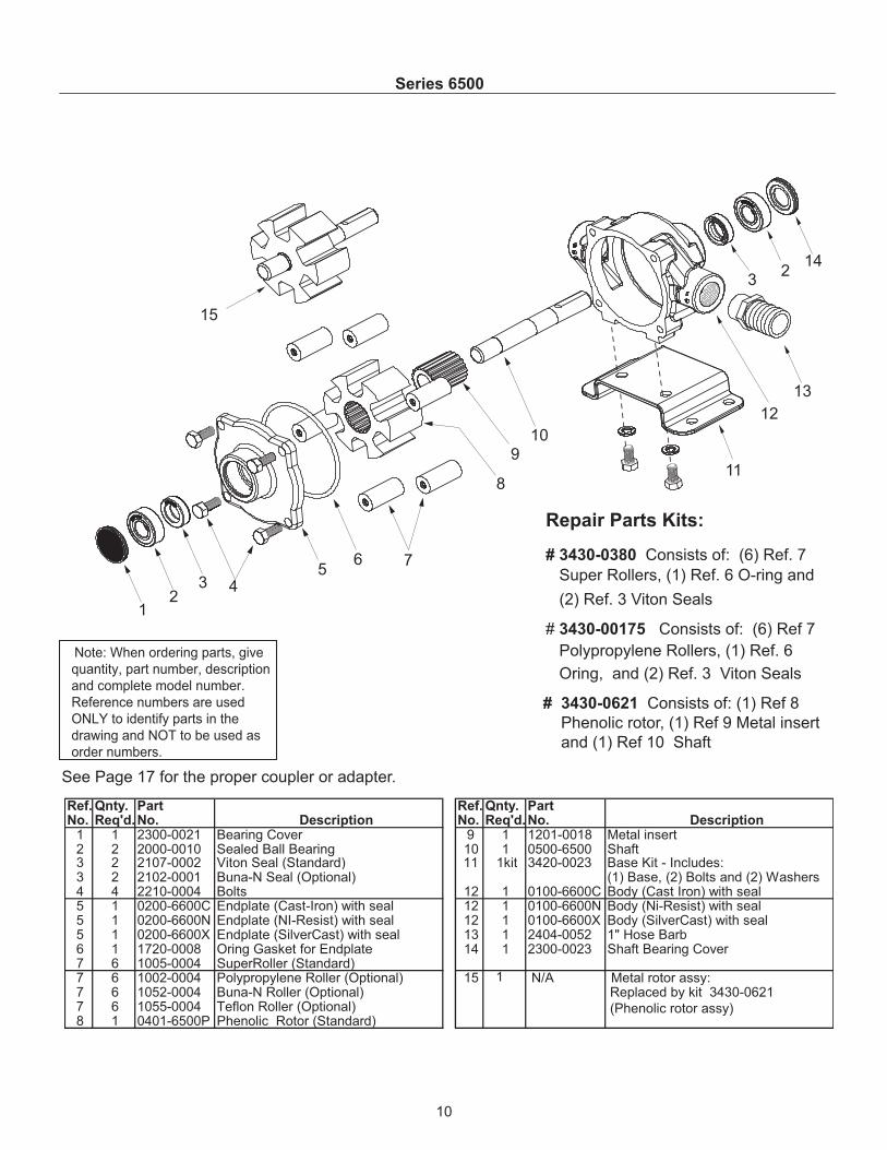
Series 6500
Note: When ordering parts, give
quantity, part number, description
and complete model number.
Reference numbers are used
ONLY to identify parts in the
drawing and NOT to be used as
order numbers.
12
3 45
6 7
8
910
11
12
13
32
14
15
See Page 17 for the proper coupler or adapter.
Repair Parts Kits:
# 3430-0380 Consists of: (6) Ref. 7
Super Rollers, (1) Ref. 6 O-ring and
(2) Ref. 3 Viton Seals
# 3430-00175 Consists of: (6) Ref 7
Polypropylene Rollers, (1) Ref. 6
Oring, and (2) Ref. 3 Viton Seals
# 3430-0621 Consists of: (1) Ref 8
Phenolic rotor, (1) Ref 9 Metal insert
and (1) Ref 10 Shaft
Ref. Qnty. Part Ref. Qnty. Part No. Req'd. No. Description No. Req'd. No. Description
1 1 2300-0021 Bearing Cover 9 1 1201-0018 Metal insert2 2 2000-0010 Sealed Ball Bearing 10 1 0500-6500 Shaft3 2 2107-0002 Viton Seal (Standard) 11 1kit 3420-0023 Base Kit - Includes:3 2 2102-0001 Buna-N Seal (Optional) (1) Base, (2) Bolts and (2) Washers4 4 2210-0004 Bolts 12 1 0100-6600C Body (Cast Iron) with seal5 1 0200-6600C Endplate (Cast-Iron) with seal 12 1 0100-6600N Body (Ni-Resist) with seal5 1 0200-6600N Endplate (NI-Resist) with seal 12 1 0100-6600X Body (SilverCast) with seal5 1 0200-6600X Endplate (SilverCast) with seal 13 1 2404-0052 1" Hose Barb6 1 1720-0008 Oring Gasket for Endplate 14 1 2300-0023 Shaft Bearing Cover7 6 1005-0004 SuperRoller (Standard) 7 6 1002-0004 Polypropylene Roller (Optional) 15 N/A Metal rotor assy: 7 6 1052-0004 Buna-N Roller (Optional) Replaced by kit 3430-0621
(Phenolic rotor assy)7 6 1055-0004 Teflon Roller (Optional)8 1 0401-6500P Phenolic Rotor (Standard)
1

11
SERIES 7560
1
23
4
56
7
89
10
1112
32
13
14
15
16
See Page 17 for the proper coupler or adapter.
Note: When ordering parts, give
quantity, part number, description
and complete model number.
Reference numbers are used
ONLY to identify parts in the
drawing and NOT to be used as
order numbers.
Repair Parts Kits:
# 3430-0381 Consists of: (8) Ref. 7
Super Rollers, (1) Ref. 6 O-ring and
(2) Ref. 3 Viton Seals
# 3430-0167 Consists of: (8) Ref 7
Polypropylene Rollers, (1) Ref. 6
Oring, and (2) Ref. 3 Viton Seals
# 3430-0622 Consists of: (1) Ref. 8
Phenolic rotor, (1) Ref. 9 Shaft, and
(1) Ref. 15 Key
Ref. Qnty. Part Ref. Qnty. Part No. Req'd. No. Description No. Req'd. No. Description
1 1 2300-0020 Bearing Cover 8 1 0403-7500P Phenolic (Standard)2 2 2008-0001 Sealed Ball Bearing 9 1 0510-7500 Shaft (416 Stainless)3 2 2112-0003 Viton Seal (Standard) 10 1 kit 3420-0003 Base Kit - Includes:3 2 2112-0001 Buna-N Seal (Optional) (1) Base, (3) Boltsand (3) Washers4 6 2210-0004 Bolts 11 1 0104-7500C Body (Cast Iron) with seal5 1 0204-7500C Endplate (Cast-Iron) with seal 11 1 0104-7500N Body (Ni-Resist) with seal5 1 0204-7500N Endplate (NI-Resist) with seal 11 1 0104-7500X Body (SilverCast) with seal5 1 0204-7500X Endplate (SilverCast) with seal 12 1 2404-0052 1" Hose Barb6 1 1720-0014 Oring Gasket for Endplate 13 1 2300-0022 Shaft Bearing Cover7 8 1005-0004 SuperRoller (Standard) 14 1 1610-0005 Key7 8 1002-0004 Polypropylene Roller (Optional) 15 1 1610-0059 Key (Stainless Steel)7 8 1052-0004 Buna-N Roller (Optional) 16 1 N/A Metal rotor assembly. Use kit 7 8 1055-0004 Teflon Roller (Optional) 3430-0622 (Phenolic rotor)

12
Series 7700
Note: When ordering parts, give
quantity, part number, description
and complete model number.
Reference numbers are used
ONLY to identify parts in the
drawing and NOT to be used as
order numbers.
See Page 17 for the proper coupler or adapter.
12
3 4
5
6 7
8
9
10
11
3
2
12
13
14
15
16
Repair Parts Kits:
# 3430-0381 Consists of: (8) Ref. 7
Super Rollers, (1) Ref. 6 O-ring and
(2) Ref. 3 Viton Seals
# 3430-0167 Consists of: (8) Ref 7
Polypropylene Rollers, (1) Ref. 6
Oring, and (2) Ref. 3 Viton Seals
# 3430-0623 Consists of: (1) Ref.8
Phenolic rotor, (1) Ref. 9 Shaft
and (1) Ref. 15 Key
Ref. Qnty. Part Ref. Qnty. Part No. Req'd. No. Description No. Req'd. No. Description
1 1 2300-0020 Bearing Cover 8 1 0401-7700P Phenolic (Standard)2 2 2008-0001 Sealed Ball Bearing 9 1 0510-7500 Shaft (416 Stainless)3 2 2112-0003 Viton Seal (Standard) 10 1 kit 3420-0010 Base Kit - Includes:3 2 2112-0001 Buna-N Seal (Optional) (1) Base and (4) Bolts 4 6 2210-0004 Bolts 11 1 0100-7700C Body (Cast Iron) with seal5 1 0200-7700C Endplate (Cast-Iron) with seal 11 1 0100-7700N Body (Ni-Resist) with seal5 1 0200-7700N Endplate (NI-Resist) with seal 11 1 0100-7700X Body (SilverCast) with seal5 1 0200-7700X Endplate (SilverCast) with seal 12 1 2404-0052 1" Hose Barb6 1 1720-0014 Oring Gasket for Endplate 13 1 2300-0022 Shaft Bearing Cover7 7 1005-0004 SuperRoller (Standard) 14 1 1610-0005 Key7 7 1002-0004 Polypropylene Roller (Optional) 15 1 1610-0059 Key (Stainless Steel)7 7 1052-0004 Buna-N Roller (Optional) 16 1 N/A Metal rotor assembly. Replaced by kit7 7 1055-0004 Teflon Roller (Optional) 3430-0623 (Phenolic rotor)

See Page 17 for the proper coupler or adapter.
Repair Parts Kit No. 3430-0437 Consists of: (5) Ref. 12 Super Rollers, (1)Ref. 7 O-Ring Gasket, and (2) Ref. 4 Viton Seals.
Repair Parts Kit No. 3430-0383 (Universal) Consists of: (6) Ref. 12 SuperRollers, (2) Ref. 7 O-Ring Gaskets, and (2) Ref. 4 Viton Seals.
Repair Parts Kit No. 3430-0160 Consists of: (5) Ref. 12 PolypropyleneRollers and (1) Ref. 7 O-Ring Gasket, and two Ref. 4 Buna-N Seals.
10 1 1610-0005 Key11 1 2230-0018 Set Screw11 1 2230-0034 Set Screw (SilverCast Only)
12 5 1005-0005 Super Roller (Standard)12 5 1002-0005 Polypropylene Roller (Optional) 12 5 1055-0005 Teflon Roller (Optional)13 1 0100-1700C Body (Cast Iron) with seal13 1 0100-1700N Body (Ni-Resist) with seal13 1 0100-1700X Body (SilverCast) with seal
14 1 kit 3420-0010 Base Kit — Includes: (1) Base and (4) Bolts16 1 2404-0191 1-1/4" Hose Barb24 1 2300-0020 Bearing Cover25 1 2300-0022 Shaft Bearing Cover
2A 1 6031-0258 Name Plate (Specify Pump Model #)3 2 2008-0001 Sealed Ball Bearing 4 2 2112-0003 Viton Seal (Standard)4 2 2112-0001 Buna-N Seal (Optional)
5 6 2210-0005 Bolt6 1 0200-1700C Endplate (Cast-Iron) with seal6 1 0200-1700N Endplate (Ni-Resist) with seal6 1 0200-1700X Endplate (SilverCast) with seal7 1 1720-0099 O-ring Gasket for Endplate8 1 0300-1700C Rotor (Cast Iron) with shaft (Std. Rotation)
8 1 0300-1700N Rotor (Ni-Resist) with shaft (Std. Rotation)8 1 0300-1700X Rotor (SilverCast) with shaft (Std. Rotation)8A 1 0301-1700C Rotor (Cast Iron) w/shaft (Reverse Rotation)8A 1 0301-1700N Rotor (Ni-Resist) w/shaft (Reverse Rotation)8A 1 0301-1700X Rotor (SilverCast) w/shaft (Reverse Rot.)
9 1 0500-1502 Shaft Only
Ref. Qnty. Part
No. Req'd. Number Description
Ref. Qnty. Part
No. Req'd. Number Description
IMPORTANT:
When ordering par ts, give PARTNUMBER and PART DESCRIPTION.Reference Numbers are used ONLYto point out parts in the drawing andare NOT to be used as orderingnumbers.
Repair Parts Kit No. 3430-0159 Consists of: (5) Ref. 12 PolypropyleneRollers and (1) Ref. 7 O-Ring Gasket.
Repair Parts Kit No. 3430-0161 Consists of: (5) Ref. 12 PolypropyleneRollers and (1) Ref. 7 O-Ring Gasket, and (2) Ref. 4 Viton Seals.
Repair Parts Kit No. 3430-0407 Consists of: (5) Ref. 12 Super Rollers, (1)Ref. 7 O-Ring Gasket, (2) Ref. 4 Viton Seals and (2) Ref. 3 Sealed BallBearings.
Models 1700C, 1700N, and 1700XL
13

IMPORTANT:
When ordering par ts, give PARTNUMBER and PART DESCRIPTION.Reference Numbers are used ONLYto point out parts in the drawing andare NOT to be used as orderingnumbers.
See Page 17 for the proper coupler or adapter.
253
413
14
1098
12
11
910
118A
765
43
24
2A
Repair Parts Kit No. 3430-0204 Consists of: (6) Ref. 12 Teflon Rollers, (1)Ref. 7 O-Ring Gasket, and (2) Ref. 4 Buna-N Seals.
Repair Parts Kit No. 3430-0164 Consists of: (6) Ref. 8 PolypropyleneRollers, (1) Ref. 7 O-Ring Gasket, and (2) Ref. 4 Viton Seals.
Repair Parts Kit No. 3430-0163 Consists of: (6) Ref. 8 PolypropyleneRollers, (1) Ref. 7 O-Ring Gasket, and (2) Ref. 4 Buna-N Seals.
Repair Parts Kit No. 3430-0406 Consists of: (6) Ref. 12 Super Rollers, (1)Ref. 7 O-Ring Gasket, (2) Ref. 4 Viton Seals and (2) Ref. 3 Sealed BallBearings.
10 1 1610-0005 Key11 1 2230-0018 Set Screw11 1 2230-0034 Set Screw (SilverCast Only)
12 6 1005-0005 Super Roller (Standard)12 6 1002-0005 Polypropylene Roller (Optional) 12 6 1055-0005 Teflon Roller (Optional)13 1 0100-1500C Body (Cast Iron) with seal13 1 0100-1500N Body (Ni-Resist) with seal13 1 0100-1500X Body (SilverCast) with seal
14 1 kit 3420-0004 Base Kit — Includes:(1) Base ,(4) Bolts (4) Lockwashers
24 1 2300-0020 Bearing Cover25 1 2300-0022 Shaft Bearing Cover
Ref. Qnty. Part
No. Req'd. Number Description
2A 1 6031-0258 Name Plate (Specify Pump Model #)3 2 2008-0001 Sealed Ball Bearing 4 2 2112-0001 Buna-N Seal (Standard)4 2 2112-0003 Viton Seal (Optional) (Std. for SilverCast)5 6 2210-0026 Bolt6 1 0200-1500C Endplate (Cast-Iron) with seal6 1 0200-1500N Endplate (Ni-Resist) with seal6 1 0200-1500X Endplate (SilverCast) with seal7 1 1720-0003 O-ring Gasket for Endplate8 1 0300-1502C Rotor (Cast Iron) with shaft (Std. Rotation)8 1 0300-1502N Rotor (Ni-Resist) with shaft (Std. Rotation)
8 1 0300-1502X Rotor (SilverCast) with shaft (Std. Rotation)8A 1 0301-1502C Rotor (Cast Iron) w/shaft (Reverse Rotation)8A 1 0301-1502N Rotor (Ni-Resist) w/shaft (Reverse Rotation)8A 1 0301-1502X Rotor (SilverCast) w/shaft (Reverse Rotat.)
9 1 0500-1502 Shaft Only
Ref. Qnty. Part
No. Req'd. Number Description
Repair Parts Kit No. 3430-0383 (Universal) Consists of: (6) Ref. 12Super Rollers, (2) Ref. 7 O-Ring Gaskets, and (2) Ref. 4 Viton Seals.
Repair Parts Kit No. 3430-0388 Consists of: (6) Ref. 12 Super Rollersand (1) Ref. 7 O-Ring Gasket.
Repair Parts Kit No. 3430-0386 Consists of: (6) Ref. 12 Super Rollers, (1)Ref. 7 O-Ring Gasket, and (2) Ref. 4 Viton Seals.
Repair Parts Kit No. 3430-0387 Consists of: (6) Ref. 12 Super Rollers, (1)Ref. 7 O-Ring Gasket, and (2) Ref. 4 Buna-N Seals.
Repair Parts Kit No. 3430-0162 Consists of: (6) Ref. 12 PolypropyleneRollers and (1) Ref. 7 O-Ring Gasket.
Models 1500C, 1500N, and 1500XL
14

Locking Collar Kit No. 3430-0207For Series 1200 Roller Pumps
This locking collar kit holds the pump driver shaft securelyon the tractor PTO shaft. It is designed to increase pump lifeby reducing pump and PTO shaft wear due to vibration. Toinstall locking collar:
1. Slide collar onto pump driver shaft.
2. Thread the longer set screw through the locking collarand partially through the threaded hole in the pumpdriver shaft. IMPORTANT: It is necessary to allow aminimum of 1/8" clearance between the locking collarand the pump driver shaft at set screw.
3. Thread the shorter set screw into the other threadedhole in the locking collar.
4. Slide pump driver hub over PTO shaft. Be sure PTOgroove is under set screw.
5. Tighten the longer screw very securely with a 3/16"allen wrench.
6. Tighten the shorter set screw very securely with thesame wrench. This binds set screw which prevents itfrom coming loose.
7. NOTE: Locking collar is off-center on the pump drivershaft when properly installed.
10 1 0500-1200 Shaft11 1 2230-0018 Set Screw12 1 0100-1200C Body (Cast Iron) with seal13 1 1610-0005 Key14 1 kit 3410-0031 Set Screw Kit
15 1 1320-0081 1-3/8" 6-spline 540 rpm PTO Adapter(Forged Steel) Includes Kit No. 3410-0031
16 1 kit 3430-0207 Locking Collar Kit — Includes:(1) Collar and (2) Setscrews
ORDER PARTS FROM YOUR SUPPLIER
Parts Kit No. 3430-0374 Consists of (4) Ref. 8 Super Rollers, (1) Ref 7O-Ring, (2) Ref 4 Buna-N Seals
Ref. Qnty. Part
No. Req'd. Number Description
Ref. Qnty. Part
No. Req'd. Number Description
1 1 1800-0013 Retainer Ring2 1 2840-0049 Bearing Cover2A 1 6031-0258 Name Plate (Specify Pump Model #)3 2 2001-0006 Ball Bearing4 2 2112-0008 Buna-N Seal (Standard)4 2 2112-0009 Viton Seal (Optional)
5 4 2210-0019 Hex Head Bolt6 1 0200-1200C Endplate (Cast-Iron) with seal7 1 1720-0127 O-ring Gasket for Endplate8 4 1005-0006 Super Roller (Standard)9 1 0300-1200C Rotor (Cast Iron) with shaft (Std. Rotation)9A 1 0301-1200C Rotor (Cast Iron) w/shaft (Reverse Rotation)
Model 1200
15

Note: "HP" is electrical horsepower. Consult your gas engine supplier for engine horsepower required.
PSI 0 25 50 100 150RPM GPM HP GPM HP GPM HP GPM HP GPM HP540 33.1 .51 29.7 1.02 27.8 1.45 24.3 2.46 21.0 3.54600 36.8 .66 33.6 1.15 31.7 1.68 28.3 2.78 25.0 3.951000 62.1 2.02 58.5 3.04 56.9 3.69 53.9 5.31 50.9 7.12
BAR 0 3.4 6.9 10.3 13.8 17.2 20.7RPM LPM HP LPM HP LPM HP LPM HP LPM HP LPM HP LPM HP540 36.7 0.08 30.3 0.38 27.3 0.68 25 0.97 21.2 1.29 18.5 1.65 16.3 1.911000 68.9 0.2 62.4 0.71 58.3 1.26 55.6 1.8 53 2.34 50.7 2.91 48.1 3.471200 82.5 0.3 76.1 0.9 72.3 1.51 68.9 2.14 65.5 2.84 62.4 3.48 59.4 4.17
BAR 0 3.4 6.9 10.3 13.8RPM LPM HP LPM HP LPM HP LPM HP LPM HP540 53.7 0.23 48.8 0.56 45 1.1 42.4 1.64 39 2.22600 57.9 0.28 53 0.62 49.2 1.2 46.6 1.8 43.9 2.44800 83.6 0.37 78.3 0.86 73.8 1.66 70.4 2.4 67.4 3.26
PSI 0 25 50 75 100 125 150RPM GPM HP GPM HP GPM HP GPM HP GPM HP GPM HP GPM HP1100 5.5 .06 4.9 .14 4.4 .24 4.1 .34 3.8 .41 3.5 .51 3.3 .621400 7.1 .10 6.4 .20 5.9 .32 5.6 .44 5.3 .56 5.0 .68 4.8 .781800 9.1 .14 8.5 .30 8.0 .46 7.6 .62 7.3 .78 7.0 .95 6.7 1.1
4101 Models
PSI 0 25 50 75 100 125 150RPM GPM HP GPM HP GPM HP GPM HP GPM HP GPM HP GPM HP1800 5.0 .11 4.8 .21 4.5 .34 4.2 .45 3.9 .56 3.7 .68 3.4 .782200 6.2 .14 5.8 .27 5.6 .40 5.4 .55 5.0 .68 4.7 .82 4.4 .962600 7.2 .16 6.9 .30 6.6 .46 6.4 .62 6.0 .76 5.7 .92 5.4 1.08
Ser
ies
6500
Ser
ies
7700
Ser
ies
7560
Ser
ies
1700
Ser
ies
1500
Ser
ies
1200
PSI 0 50 100 150 200RPM GPM HP GPM HP GPM HP GPM HP GPM HP540 25.0 .27 21.0 1.18 19.0 2.13 17.0 2.89 15.0 3.85600 28.0 .34 24.5 1.39 22.0 2.36 20.0 3.34 18.0 4.391000 45.0 1.42 43.0 3.0 41.0 4.67 39.0 6.07 - -
PSI 0 50 100 150 200RPM GPM HP GPM HP GPM HP GPM HP GPM HP540 14.2 .23 12.9 .56 11.9 1.10 11.2 1.64 10.3 2.22600 15.3 .28 14.0 .62 13.0 1.20 12.3 1.80 11.6 2.44800 22.1 .37 20.7 .86 19.5 1.66 18.6 2.40 17.8 3.26
BAR 0 1.7 3.4 5.2 6.9 8.6 10.3RPM LPM HP LPM HP LPM HP LPM HP LPM HP LPM HP LPM HP1800 18.9 0.11 18.1 0.21 17.0 0.34 15.9 0.45 14.8 0.56 14.0 0.68 12.9 0.782200 23.5 0.14 21.9 0.27 21.2 0.4 20.4 0.55 18.9 0.68 17.8 0.82 16.6 0.962600 27.3 0.16 26.1 0.3 25.0 0.46 24.2 0.62 22.7 0.76 21.6 0.92 20.4 1.08
BAR 0 1.7 3.4 5.2 6.9 8.6 10.3RPM LPM HP LPM HP LPM HP LPM HP LPM HP LPM HP LPM HP1100 20.8 0.06 18.5 0.14 16.6 .24 15.5 0.34 14.4 0.41 13.2 0.51 12.5 0.621400 26.9 0.1 24.2 0.2 22.3 0.32 21.2 0.44 20.1 0.56 18.9 0.66 18.2 0.781800 34.4 0.14 32.2 0.3 30.3 0.46 28.7 0.62 27.6 0.78 26.5 0.95 25.4 1.1
BAR 0 3.4 6.9 10.3 13.8 17.2 20.7RPM LPM HP LPM HP LPM HP LPM HP LPM HP LPM HP LPM HP540 45.4 0.33 42 0.74 39 1.25 36 1.77 32.5 2.26 29.5 2.78 26.9 3.3800 69.3 0.89 66.2 1.26 64 1.95 60.9 2.65 58.7 3.4 54.9 4.2 51.9 4.91000 85.2 1.56 83.3 1.78 80.6 2.53 78 3.5 75.7 4.2 71.5 5.3 68.1 6.1
BAR 0 3.4 6.9 10.3 13.8RPM LPM HP LPM HP LPM HP LPM HP LPM HP540 94.6 0.27 79.5 1.18 71.9 2.13 64.3 2.89 56.8 3.85600 106 0.34 92.7 1.39 83.3 2.36 75.7 3.34 68.1 4.391000 170 1.42 163 3.00 155 4.67 148 6.07 - -
BAR 0 1.7 3.4 6.9 10.3RPM LPM HP LPM HP LPM HP LPM HP LPM HP540 125 0.51 112 1.02 105 1.45 92 2.48 79.5 3.54600 139 0.66 127 1.15 120 1.68 107 2.78 94.6 3.951000 235 2.02 221 3.04 215 3.69 204 5.31 193 7.12
PSI 30 50 100 150RPM GPM HP GPM HP GPM HP GPM HP540 - - 48.8 2.70 44.2 4.47 41.0 6.17600 - - 54.3 3.12 50.5 5.05 47.0 6.94800 74.0 4.0 72.5 5.08 69.5 7.31 67.0 9.60
Metric American Standard
4001 Models
PSI 0 50 100 150 200 250 300RPM GPM HP GPM HP GPM HP GPM HP GPM HP GPM HP GPM HP540 9.7 .08 8.0 .38 7.2 .68 6.6 .97 5.6 1.29 4.9 1.65 4.3 1.911000 18.2 .20 16.5 .71 15.4 1.26 14.7 1.80 14.0 2.34 13.4 2.91 12.7 3.471200 21.8 .30 20.1 .90 19.1 1.51 18.2 2.14 17.3 2.84 16.5 3.48 15.7 4.17
PSI 0 50 100 150 200 250 300RPM GPM HP GPM HP GPM HP GPM HP GPM HP GPM HP GPM HP540 12 .33 11.1 .74 10.3 1.25 9.5 1.77 8.6 2.26 7.8 2.78 7.1 3.3800 18.3 .89 17.5 1.26 16.9 1.95 16.1 2.65 15.5 3.4 14.5 4.2 13.7 4.91000 22.5 1.56 22 1.78 21.3 2.53 20.6 3.5 20 4.2 18.9 5.3 18.0 6.1
BAR .3 .5 1 1.5RPM LPM HP LPM HP LPM HP LPM HP540 - - 184.7 2.01 167.3 3.33 155.2 4.60600 - - 205.5 2.33 191.2 3.76 177.9 5.18800 280.1 2.98 274.4 3.79 263.1 5.45 253.6 7.16
Ser
ies
4000
16
Roller Pump Performance Chart

Quick Couplers(Female to Female)
Part Number PTO (I.D.) Pump End (I.D.) Material RPM Pump Model
1320-0015 3/4" 5/8" steel * 4000, 6500
1320-0016 5/8" 5/8" steel * 4000, 6500
1320-0022 13⁄8" (6 spline) 5/8" die cast 540 6500
1320-0033 13⁄8" (6 spline) 15/16" die cast 540 1500, 1700, 7560, 7700
1320-0038 13⁄8" (21 spline) 15/16" die cast 1000 1500, 1700, 7560
1320-0053 13⁄8" (21 spline) 5/8" die cast 1000 4000, 6500
1320-0054 3/4" 15/16" die cast * 1500, 1700, 7560,7700
1320-0059 13⁄8" (6 spline) 1" die cast 540 1200/5200
1320-0076 13⁄8" (6 spline) 15/16" forged steel 540 1500, 1700, 7560, 7700
1320-0077 13⁄8" (6 spline) 5/8" forged steel 540 6500
1320-0078 13⁄8" (21 spline) 15/16" forged steel 1000 1500, 1700, 7560
1320-0079 13⁄8" (21 spline) 5/8" forged steel 1000 4000, 6500
1320-0080 13⁄4" (20 spline) 15/16" forged steel 1000 1500, 1700, 7560
1320-0081 13⁄8" (6 spline) 1" forged steel 540 1200/5200
Part Number PTO (I.D.) Pump End (I.D.) Material RPM Pump Model
1321-0006 13⁄8" (6 spline) 5/8" die cast 540 6500
1321-0007 13⁄8" (6 spline) 15/16" die cast 540 1500, 1700, 7560, 7700
1321-0008 13⁄8" (21 spline) 5/8" die cast 1000 4000, 6500
1321-0009 13⁄8" (21 spline) 15/16" die cast 1000 1500, 1700, 7560
1321-0012 13⁄8" (multi-speed) 5/8" die cast 540/1000 4000, 6500
1321-0013 13⁄8" (multi-speed) 15/16" die cast 540/1000 1500, 7560, 7700
1323-0072 13⁄8" (6 spline) 15/16" forged steel 540 1500,1700, 7560, 7700
1323-0073 13⁄8" (21 spline) 15/16" forged steel 1000 1500, 1700, 7560
1323-0074 13⁄8" (6 spline) 5/8" forged steel 540 6500
1323-0075 13⁄8" (21 spline) 5/8" forged steel 1000 4000, 6500
1323-0076 13⁄8" (multi-speed) 15/16" forged steel 540/1000 1500, 1700, 7560
1323-0077 13⁄8" (multi-speed) 5/8" forged steel 540/1000 4000, 6500
List of Dimensions — Hypro Adapters
PTO Adapters(Female to Female)
17
* Refer to the recommended pump rpm.

Use a SilverCast™, Ni-Resist, or cast iron pump, Super Rollers and Viton.seals
NOTE: For weed control chemicals containingglyphosate (such as Roundup®) or otheracidics, use only a SilverCast pump with Superor polypropylene rollers and Viton seals. Teflonrollers may be used up to 100 psi.
Use a SilverCast, Ni-Resist or cast iron pump with SuperRollers. Use Viton or leather seals.
Use a SilverCast or Ni-Resist pump with polypropylene rollers and Buna-N seals.
Use a SilverCast, Ni-Resist or cast iron pump, Super,rubber or polypropylene rollers and Buna-N or Viton seals.
NOTE: Limit pressure to 100 psi when using rubber rollers or wettable powders.
Use SilverCast pump, Viton seals, polypropylene orTeflon rollers.
NOTE: Limit pressure to 100 psi when using Teflon rollers.
WEED CONTROLCHEMICALS
INSECT CONTROL
BRUSH CONTROL
PEST CONTROL CHEMICALS, FUMIGANTS, ETC.
LIQUID FERTILIZERS
POWDEREDFERTILIZERS
PUMPING
SPRAYING
MATERIAL HANDLING
ACIDS
Emulsions, soluble powders, sodium arsenate.
Emulsions not containing aromatic solvents.
Heavy-duty sprays using diesel oil for carrier.
This category or use includes mosquitosprays, termite control liquids, nematocides, soil and grain fumigantswhere any of the following chemicalswith aromatic solvents are present:
Pentachlorophenol, xylene, xylol, ben-zene, high sulphur fuel or diesel oil.Fumigants containing: ethylene dichloride, ethylene dibromide, carbontetrachloride, perchlorethylene,trighlorethylene, methyl bromide, andother aromatic solvents.
Up to 32% nitrogen content, or others if the liquid is at atmospheric pressure and the temperature is handled.
Fertilizers dissolved in water (greenhouse plant food).
Large quantities of plain water.
Wettable powder sprays.
Heavy abrasive powders in suspension.
Mild sulfuric acid for spraying. Mild muri-atic acid, inhibited muriatic, etc.
Application Specific Chemicals Suggested Pump, Rollers and Seals
Material options for rollers and seals are
listed in the order of recommendations for
usage. These recommendations are only a
general guide. For suggestions on specific
chemicals or applications, call Hypro’s
Technical/Applications Department at
(800) 445-8360.
WHAT Roller Pump, Rollers and Seals
SHOULD YOU USE?
18

• NOTES •
19

Hypro (“Hypro”) warrants to the original purchaser of its products (the “Purchaser”) that such products will be free from defects in mate-rial and workmanship under normal use for the period of one (1) year for all products except: oil crankcase plunger pumps will be freefrom defects in material and workmanship under normal use for the period of five (5) years, and accessories will be free from defects inmaterial and workmanship under normal use for the period of ninety (90) days. In addition, Hypro warrants to the purchaser all forgedbrass pump manifolds will be free from defects in material and workmanship under normal use and from damage resulting from environ-mental conditions for the life of the pump.
“Normal use” does not include use in excess of recommended maximum speeds, pressures, vacuums and temperatures, or use requir-ing handling of fluids not compatible with component materials, as noted in Hypro product catalogs, technical literature, and instructions.This warranty does not cover freight damage, freezing damage, normal wear and tear, or damage caused by misapplication, fault, negli-gence, alterations, or repair that affects the performance or reliability of the product.
THIS WARRANTY IS EXCLUSIVE. HYPRO MAKES NO OTHER WARRANTY, EXPRESS OR IMPLIED, INCLUDING BUT NOT LIM-ITED TO ANY WARRANTY OF MERCHANTABILITY OR FITNESS FOR A PARTICULAR PURPOSE.
Hypro’s obligation under this warranty is, at Hypro’s option, to either repair or replace the product upon return of the entire product to theHypro factory in accordance with the return procedures set forth below. THIS IS THE EXCLUSIVE REMEDY FOR ANY BREACH OFWARRANTY.
IN NO EVENT SHALL HYPRO BE LIABLE FOR ANY INCIDENTAL OR CONSEQUENTIAL DAMAGES OF ANY KIND, WHETHERFOR BREACH OF ANY WARRANTY, FOR NEGLIGENCE, ON THE BASIS OF STRICT LIABILITY, OR OTHERWISE.
Return Procedures
All pumps or products must be flushed of any chemical (ref. OSHA Section 0910.1200 (d)(e)(f)(g)(h) and hazardous chemicalsmust be labeled before being shipped* to Hypro for service or warranty consideration. Hypro reserves the right to request aMaterial Safety Data sheet from the Purchaser for any pump or product Hypro deems necessary. Hypro reserves the right to “dispositionas scrap” pumps or products returned which contain unknown substances, or to charge for any and all costs incurred for chemical test-ing and proper disposal of components containing unknown substances. Hypro requests this in order to protect the environment andpersonnel from the hazards of handling unknown substances.
For technical or application assistance, call the Hypro Technical/Application number: 1-800-445-8360.To obtain service or warranty assistance, call the Hypro Service and Warranty number: 1-800-468-3428;or call the Hypro Service and Warranty FAX: (651) 766-6618.Be prepared to give Hypro full details of the problem, including the following information:1. Model number and the date and from whom you purchased your pump.2. A brief description of the pump problem, including the following:
• Liquid pumped. State the pH and any non-soluble • Drive type (gas engine/electric motor; direct/belt drive;materials, and give the generic or trade name. tractor PTO) and rpm of pump.
• Temperature of the liquid and ambient environment. • Viscosity (of oil, or other than water weight liquid).• Suction lift or vacuum (measured at the pump). • Elevation from the pump to the discharge point.• Discharge pressure. • Size and material of suction and discharge line.• Size, type, and mesh of the suction strainer. • Type of spray gun, orifice size, unloader/relief valve.
Hypro may request additional information, and may require a sketch to illustrate the problem.Contact the factory to receive a return material authorization before sending the product. All pumps returned for warranty work shouldbe sent shipping charges prepaid to:
HYPRO Attention: Service Department375 Fifth Avenue NWNew Brighton, Minnesota 55112-3288
*Carriers, including U.S.P.S., airlines, UPS, ground freight, etc., require specific identification of any hazardous materials beingshipped.
Failure to do so may result in a substantial fine and/or prison term. Check with your shipping company for specific instructions.
Printed in the USA2004 Hypro
Limited Warranty on Hypro Roller Pumps