Embed Size (px)
Citation preview

Series 1542A-65SP, 1543A-65SP & 1543A-65TSP1542A-160HSP, 1543A-160HSP & 1543A-160HTSP
Gas Engine-Driven, Self-Priming, SAE Mount,Centrifugal Pumps
Installation, Operation, Repair and Parts ManualDescription
Form L-1533 Rev. D
Hypro Self-Priming Centrifugal Pumps handle big, high- capacity, liquid transfer jobs with ease. Use them for transferring water, liquid fertilizers, and other chemicals compatible with pump materials. Make short work of other
farm jobs: filling nurse tanks, watering seedbeds, and transferring liquids. This self-priming model makes it ideal for de-watering applications.
1542A-65SP, 1542A-160HSP 1542A-550BSP
Close-Coupled, Gas Engine-Driven Self-Priming Centrifugal Pump
Max. Flow Rate: ........................... 147 GPMMax. Pressure: .................................50 PSIMax. Total Head .............................115 FT.Max. Suction Lift: ..............................28 FT.Ports: ........................................ 2” NPT Inlet
2” NPT OutletEngine.........PowerPro™ 6.5 HP or Honda GX160
Briggs & Stratton 550
1543A-65SP, 1543A-160HSP
Close-Coupled, Gas Engine-Driven Self-Priming Centrifugal Pump
Max. Flow Rate: ........................... 259 GPMMax. Pressure: .................................43 PSIMax. Total Head .............................100 FT.Max. Suction Lift: ..............................28 FT.Ports: ........................................ 3” NPT Inlet
3” NPT OutletEngine.........PowerPro™ 6.5 HP or Honda GX160
1543A-65TSP, 1543A-160HTSP
Close-Coupled, Gas Engine-Driven Self-Priming Centrifugal Trash PumpMax. Flow Rate: ........................... 272 GPMMax. Pressure: .......... ......................50 PSI Max. Total Head ............................. 115 FT.Max. Suction Lift: .............................. 28 FT.Ports: ........................................ 3” NPT Inlet
3” NPT OutletSolids Handling Capability (max. dia.):1-1/8” solids Engine.........PowerPro™ 6.5 HP or Honda GX160
WARNING: Do not pump flammable or explosive fluids such as gasoline, fuel oil, kerosene, etc. Do not use in explosive atmospheres. The pump should be used only with liquids that are compatible with the pump component materials. Failure to follow this warning can result in personal injury and/or property damage and will void the product warranty.
1. DO NOT EXCEED recommended speed, pressure and temperature (140˚ F) for pump and equipment being used.
2. BEFORE SERVICING, drain all liquids from the system and flush. Remove the spark plug wire from the spark plug before servicing the pump or engine.
3. Secure the discharge lines before starting the pump. An unsecured line may whip, causing personal injury and/or property damage.
4. Check hose for weak or worn condition before each use. Make certain that all connections are tight and secure.
5. Periodically inspect the pump and the system components. Perform routine maintenance as required (see Maintenance section).
6. Protect pump from freezing conditions by draining liquid and pumping a permanent-type automobile antifreeze containing a rust inhibitor through the system, coating the pump interior. A 50% mixture with water is recommended.
7. Do not operate a gasoline engine in an enclosed area. Be sure the area is well ventilated.
WARNING: Gasoline is a highly combustible fuel. The improper use, handling, or storage of gasoline can be dangerous. Never touch or fill a hot engine.
8. Use only pipe, hose and fittings rated for the maximum psi rating of the pump.
9. Do not use these pumps for pumping water or other liquids for human or animal consumption.
General Safety Information
HYPRO®
California Proposition 65 Warning -- This product and related accessories contain chemicals known to the State of California to cause cancer, birth defects or other reproductive harm.

2
Preparations before Starting the Engine1. Fuel: Check fuel level in tank. Do not over fill tank.
Use fresh, clean automotive fuel. Note: DO NOT FILL FUEL TANK WHEN ENGINE IS RUNNING.
2. Engine Oil: Before checking or refilling with engine oil, make sure the engine is stopped and placed on a stable, level surface. Use oil recommended for ambient air temperatures that the engine will be running at. See chart below. Change oil according to manufacturer’s recommendation. (Once after the first 20 hours and every 100 hours thereafter.)
Air Temperature Single-grade Oil85° F #40W60° F #30W32° F #20W
3. Priming Water: IMPORTANT: PUMP MUST NOT BE RUN DRY. On self-priming pumps, only the chamber needs to be filled with liquid. The pump must not run unless the priming chamber is completely filled with liquid because there is a danger of damaging the mechanical seal, which depends on the liquid for its lubrication. Self-priming models can be primed by removing the filler cap, located at the top of the pump where the discharge line is mounted to the pump, and filling the priming chamber with liquid. The priming chamber will fill to the level of the inlet port. After use, the priming chamber should be flushed and drained to avoid
chemical corrosion and damage from freezing. Drain by removing the lower drain plug located at the bottom of the casing.
Starting the PumpIMPORTANT: Before starting engine, be sure the priming chamber is filled with liquid and the discharge hose is secure.
1. Turn engine switch located by recoil starter to ON position.
2. Turn the fuel cock to ON.3. Push the throttle lever to a slightly open position.4. Operation of choke lever.
When engine is cold: In cold weather, start engine with choke in fully closed position. In warm weather, start engine with choke in half-closed position. When engine is warm: Start engine with choke in fully open position.
5. Start engine by pulling recoil starter out quickly and forcefully. Repeat pulling until the engine starts.
Operation of the Pump1. Idle the engine for 3 to 5 minutes to warm it up.2. Open the throttle lever to the upper zone after engine
has warmed up.3. Once the pump has primed, you will note a load on
the engine; adjust RPMs to proper speed for your pumping application.
Hazardous Substance Alert
Please Note: It is illegal to ship or transport any hazardous chemicals without United States Environmental Protection Agency Licensing.
1. Always drain and flush pumps before servicing or disassembling for any reason.
2. Before returning unit for repair, drain out all liquids and flush unit with neutralizing liquid. Then, drain the pump. Attach a tag or include a written notice certifying that this has been done.
3. Never store pumps containing hazardous chemicals.
Plumbing InstallationPreliminary to MountingBefore setting up the pump for operation, check to see that the motor and pump turn freely by hand. If it cannot be turned over by pulling on the recoil starter, open casing to check for obstructions lodged in pump.
Selecting the Suction LineTo get full capacity of the pump, the suction line should be the same size as the pump suction port. If suction hose is longer than approximately 6 feet, use next size larger hose. The suction line must be free of air leaks. All joints and connections of the suction line must be tightened securely so that no additional air may enter the suction side through a
loose connection. Use a good grade of suction hose that will not collapse.
Basket StrainerThe basket strainer supplied with this pump is to be used when transferring solutions that may contain debris and solids which could become lodged in the pump or damage the impeller. Because of the high flow capacity of this pump, unknown debris could be siphoned off the bottom of the tank. Install the strainer on the suction side of the pump whenever possible to avoid pump damage.
Operation and Maintenance

Operation and Maintenance(Operation and Maintenance Continued)
Always flush pump with water or neutralizing agent before servicing. Pump Housing DisassemblyFor this pump model, seal replacement requires that the pump be fully removed from the engine. Observe carefully the disassembly process, (orientation and order of part assembly) to ensure an easy assembly process.1. Pull spark plug wire off spark plug for safety
considerations. Remove the four bolts holding the casing to the casing cover and frame using a 14mm socket wrench. Tap pump casing on the discharge port with a rubber hammer, if necessary, to break it loose from the casing cover. Check inside pump casing. If badly eroded or damaged, pump casing should be replaced. Remove O-rings from casing cover and volute.
2. Remove volute and inspect for wear. Replace if eroded.3. Remove impeller by turning it counterclockwise using a
socket and impact wrench. If an impact wrench is not available, it may be necessary to hold the crankshaft from turning. To keep the crankshaft from turning during disassembly, remove the three bolts holding the recoil starter using a 10mm socket wrench. Then, using a pipe wrench or another tool, hold the starter hub and spin the impeller bolt off. Look for shims that may be present between the impeller and shaft. This shim is
for obtaining the proper clearance between the impeller and volute. Be careful not to damage the starter hub while gripping it with the wrench.
4. Between the impeller and casing cover is the mechanical seal. On the backside of the impeller is the seal’s ceramic seat. If either part of the seal is damaged, with cracked or scuffed surfaces, the seal will fail to perform satisfactory and will leak. To remove the seal seat from the impeller, use a small blade screwdriver and wedge the seal seat out and discard. To remove the mechanical seal, it is necessary to first remove the casing cover by removing the four bolts holding it to the engine, using 13mm socket wrench. Note that these bolts have seal washers on them and must not be damaged. From the backside of the casing cover, press the mechanical seal out and discard it.
Stopping the Pump1. Stop pump for a short time:
Run engine throttled all the way down (fully to the right). Turn engine switch to OFF position.
2. Stopping pump for storage: Turn fuel cock to OFF position instead of turning the engine switch off. Let the engine idle for 2 to 3 minutes until fuel in carburetor is depleted and engine stops. If a valve is installed on the discharge hose, you may run pump with valve closed during this procedure. Note: Pump must not be run dry. Make sure there is water in the priming chamber.
Storage1. Drain pump. Flush Pump after Use.
One of the most common causes for faulty pump per-formance is gumming or corrosion inside the pump. Flush the pump and entire system with a solution
that will chemically neutralize the liquid pumped. Mix according to the manufacturer’s directions. This will dissolve most residues remaining in the pump, leaving the inside of the pump clean and ready for use. To Prevent Corrosion: After cleaning the pump as directed above, flush it with permanent-type automotive antifreeze (Prestone, Zerex, etc.) containing a rust inhibitor. Use a 50% solution; half antifreeze and half water, or fill the pump with FLUID FILM and drain it. A protective coating of FLUID FILM will remain on the inner pump surfaces. Save the excess FLUID FILM for the next application. Plug ports to keep out air during storage. For short periods of idleness, noncorrosive liquids may be left in the pump, BUT AIR MUST BE KEPT OUT. Plug the ports or seal port connections.
2. Drain all the fuel from the fuel tank, fuel lines, and filter.
3. Store pump in a clean, dry environment.
3
Repair Instructions

4
Clean-up of Pump HousingIf necessary, clean the pump casing, volute, and casing cover using a solvent to remove debris and corrosion particles. Use a wire brush to further remove buildup of debris if it doesn’t soak loose.
Seal Replacement and Pump Housing Assembly1. Apply a light bead of RTV sealant to the top edge of the
seal cavity on the casing cover.2. Insert the stationary portion of the new mechanical seal
by carefully pushing only on the outer metal ring as you press it into the casing cover. Use a tool with 1 1/2” ID, such as a 1 1/2” PVC pipe, 4” long, that fits over the carbon face of the seal, but pushes only on the metal ring to insert the seal. Be careful to avoid scratching the seal’s carbon surface.
3. Bolt casing cover on engine. Note the arrow and word UP to indicate orientation of the casing cover. Use bolts with washers on them. Install o-ring on casing cover; replace with a new o-ring if necessary.
4. Lubricate the seal cavity of the impeller with WD-40, LPS, or equivalent, and carefully press the seal’s mating ceramic ring in place, seating it squarely on the bottom of the cavity. IMPORTANT: MAKE SURE BOTH OF THE SEAL’S SURFACES ARE CLEAN AND LUBRICATED. NEvER RUN THE SEAL SURFACES DRY.
5. Place the impeller on the shaft and spin it clockwise to tighten it on the shaft. Secure the impeller using a socket and wrench (see step 3 in Disassembly Instructions for socket size).
6. It is now necessary to check the clearance between the impeller and volute. As shown in the sketch below, measure the inside depth of the volute case (distance A). Then measure the distance from the casing cover to the front edge of the impeller (distance B). The difference between the two measurements should be between 0.024 and 0.036” or about 1/32” clearance. If the value is out of range, remove the impeller and adjust by adding or removing brass shims to achieve the correct amount of clearance.
7. Place a new o-ring in the groove of the volute’s inlet if necessary. Place the volute in place with the notch pointing up so that it mates with the casing cover at the inlet port. It may be necessary to tip the engine on its side for this assembly.
8. Carefully set casing over volute and bolt casing onto casing cover and frame. It may be necessary to tip the engine on its side for this assembly.
9. Once assembly is complete, pull on engine recoil starter with engine switch in OFF position to verify that the impeller rotates smoothly without catching. Connect spark plug wire. Assembly and inspection is now complete.
(Repair Instructions - continued)Repair Instructions
A
B
Casing CoverVolute
(A) – (B) = within 0.024 - 0.036 inches.
Impeller
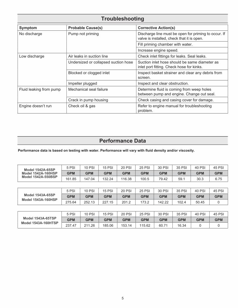
Performance DataPerformance data is based on testing with water. Performance will vary with fluid density and/or viscosity.
5
Troubleshooting
Model 1542A-65SP Model 1542A-160HSP Model 1542A-550BSP
5 PSI 10 PSI 15 PSI 20 PSI 25 PSI 30 PSI 35 PSI 40 PSI 45 PSIGPM GPM GPM GPM GPM GPM GPM GPM GPM
161.85 147.04 132.24 116.38 100.5 79.42 59.1 30.3 6.75
Model 1543A-65SP Model 1543A-160HSP
5 PSI 10 PSI 15 PSI 20 PSI 25 PSI 30 PSI 35 PSI 40 PSI 45 PSIGPM GPM GPM GPM GPM GPM GPM GPM GPM
275.64 252.13 227.15 201.2 173.2 142.22 102.4 50.45 0
Model 1543A-65TSP Model 1543A-160HTSP
5 PSI 10 PSI 15 PSI 20 PSI 25 PSI 30 PSI 35 PSI 40 PSI 45 PSIGPM GPM GPM GPM GPM GPM GPM GPM GPM
237.47 211.26 185.06 153.14 115.62 60.71 16.34 0 0
Symptom Probable Cause(s) Corrective Action(s)No discharge Pump not priming Discharge line must be open for priming to occur. If
valve is installed, check that it is open.Fill priming chamber with water.Increase engine speed.
Low discharge Air leaks in suction line Check inlet fittings for leaks. Seal leaks.Undersized or collapsed suction hose Suction inlet hose should be same diameter as
inlet port fitting. Check hose for kinks.Blocked or clogged inlet Inspect basket strainer and clear any debris from
screen.Impeller plugged Inspect and clear obstruction.
Fluid leaking from pump Mechanical seal failure Determine fluid is coming from weep holes between pump and engine. Change out seal.
Crack in pump housing Check casing and casing cover for damage.Engine doesn’t run Check oil & gas Refer to engine manual for troubleshooting
problem.

6
Models 1542A-65SP, 1542A-160HSP, 1543A-65SP, 1543A-160HSP and 1542A-550BSP
Ref.No.
Qty. Req’d. Part No. Description
1 2543-0045 PowerPro™ 6.5 hp 1 N/A* Honda GX160
1 N/A* Briggs & Stratton 5501 2801-0011 Frame4 2210-0021 Bolt4 2270-0112 Washer4 2250-0008 Hex Nut
1 1 N/A Pump Cover 2 1 N/A O-ring 196mmx4mm 3 4 N/A Sealed Washer 4 4 N/A Hex Bolt M8x55 5 1 N/A Mechanical Seal 6 1 0400-1542 Impeller 7 1 N/A Diffuser 8 1 N/A O-ring 53mmx7mm 9 1 N/A Pump Body10 1 N/A Outlet Sealed Washer11 11 2270-0112 Washer12 4 19708 Hex Bolt M8x2513 2 N/A O-ring 23x3.5mm14 2 3240-0008 Plug15 1 2404-0409 Outlet Flange16 1 N/A Check Valve17 1 2404-0405 Inlet Flange18 7 2210-0120 Hex Bolt M8x2019 4 N/A Clamp20 3 3350-0174 Strainer
Parts List: 1542A-65SP, 1542A-160HSP, 1542A-550BSPRef. No.
Qty. Req’d. Part No. Description
1 2543-0045 PowerPro™ 6.5 hp1 N/A* Honda GX1601 2801-0011 Frame4 2210-0021 Bolt4 2270-0112 Washer4 2250-0008 Hex Nut
1 1 N/A Pump Cover 2 1 N/A O-ring 196mmx4mm 3 4 N/A Sealed Washer 4 4 N/A Hex Bolt M8x55 5 1 N/A Mechanical Seal 6 1 0401-1543 Impeller 7 1 N/A Diffuser 8 1 N/A O-ring 53mmx7mm 9 1 N/A Pump Body10 1 N/A Outlet Sealed Washer11 11 2270-0112 Washer12 4 19708 Hex Bolt M8x2513 2 N/A O-ring 23x3.5mm14 2 3240-0008 Plug15 1 2404-0410 Outlet Flange16 1 N/A Check Valve17 1 2404-0406 Inlet Flange18 7 2210-0120 Hex Bolt M8x2019 4 N/A Clamp20 3 3350-0175 Strainer
Parts List: 1543A-65SP, 1543A-160HSP
IMPORTANT:
When ordering parts, give PART NUMBER and PART DESCRIPTION. Reference Numbers are used ONLY to point out parts in the drawing and are NOT to be used as ordering numbers.
Standard Seal Kit No. 3430-0800 Consists of (1) Ref. 2 O-ring, (4) Ref. 3 Sealed Washers, (1) Ref. 5 Mechanical Seal, (1) Ref. 8 O-ring, (1) Ref. 10 Outlet Sealed Washer, (2) Ref. 13 O-rings, and (1) Ref. 16 Check Valve
SiC Seal Kit No. 3430-0803 Same as standard kit but contains (1) Ref. 5 SiC mechanical seal in place of standard carbon/ceramic
Standard Seal Kit No. 3430-0799 Consists of (1) Ref. 2 O-ring, (4) Ref. 3 Sealed Washers, (1) Ref. 5 Mechanical Seal, (1) Ref. 8 O-ring, (1) Ref. 10 Outlet Sealed Washer, (2) Ref. 13 O-rings, and (1) Ref. 16 Check Valve
SiC Seal Kit No. 3430-0802 Same as standard kit but contains (1) Ref. 5 SiC mechanical seal in place of standard carbon/ceramic
1 2 3 4 5 6 7 8 910
11 12 13 14
15
16 17
18
19
20
1111 18 13 14
* For replacement parts and service center locations see Honda.com and Briggsandstratton.com respectively.

Model 1543A-65TSP, 1543A-160HTSP
7
Ref. No.
Qty. Req’d. Part No. Description
1 2543-0045 PowerPro™ 6.5 hp1 N/A* Honda GX1601 2801-0012 Frame4 2210-0021 Bolt4 2270-0112 Washer4 2250-0008 Hex Nut
1 1 N/A Pump Body 2 2 N/A O-ring 23x3.5mm 3 2 3240-0008 Plug 4 6 2280-0006 T-type Screw 5 6 N/A O-ring 5x2.65mm 6 1 N/A Check Valve 7 1 N/A Diffuser 8 1 0402-1543 Impeller 9 1 N/A Column Pin10 1 N/A O-ring 125x2.65mm11 1 N/A O-ring 260x5mm12 1 N/A Pump Cover13 1 N/A Mechanical Seal14 1 2404-0408 Hex Hose Joint15 1 3350-0176 Strainer
IMPORTANT:
When ordering parts, give PART NUMBER and PART DESCRIPTION. Reference Numbers are used ONLY to point out parts in the drawing and are NOT to be used as ordering numbers.
Standard Seal Kit No. 3430-0801 Consists of (2) Ref. 2 O-ring, (1) Ref. 6 Check Valve, (1) Ref. 10 O-ring, (1) Ref. 11 O-ring, and (1) Ref. 13 Silicon Carbide Mechanical Seal
11 10 9 8 6
5
3
42
3
21
7
12
13
14
15
* For replacement parts and service center locations see Honda.com.
Hypro/SHURflo (hereafter, “Hypro”) agricultural products are warranted to be free of defects in material and workmanship under normal use for the time periods listed below, with proof of purchase.
- Pumps: one (1) year from the date of manufacture, or one (1) year of use. This limited warranty will not exceed two (2) years, in any event. - Accessories: ninety (90) days of use.
This limited warranty will not apply to products that were improperly installed, misapplied, damaged, altered, or incompatible with fluids or components not manufactured by Hypro. All warranty considerations are governed by Hypro’s written return policy.
Hypro’s obligation under this limited warranty policy is limited to the repair or replacement of the product. All returns will be tested per Hypro’s factory criteria. Products found not defective (under the terms of this limited warranty) are subject to charges paid by the return-ee for the testing and packaging of “tested good” non-warranty returns.
No credit or labor allowances will be given for products returned as defective. Warranty replacement will be shipped on a freight allowed basis. Hypro reserves the right to choose the method of transportation.
This limited warranty is in lieu of all other warranties, expressed or implied, and no other person is authorized to give any other warranty or assume obligation or liability on Hypro’s behalf. Hypro shall not be liable for any labor, damage or other expense, nor shall Hypro be liable for any indirect, incidental or consequential damages of any kind incurred by the reason of the use or sale of any defective product. This limited warranty covers agricultural products distributed within the United States of America. Other world market areas should consult with the actual distributor for any deviation from this document.
Return ProceduresAll products must be flushed of any chemical (ref. OSHA section 1910.1200 (d) (e) (f) (g) (h)) and hazardous chemicals must be labeled/tagged before being shipped* to Hypro for service or warranty consideration. Hypro reserves the right to request a Material Safety Data Sheet from the returnee for any pump/product it deems necessary. Hypro reserves the right to “disposition as scrap” products returned which contain unknown fluids. Hypro reserves the right to charge the returnee for any and all costs incurred for chemical testing, and proper disposal of components containing unknown fluids. Hypro requests this in order to protect the environment and personnel from the hazards of handling unknown fluids.
Be prepared to give Hypro full details of the problem, including the model number, date of purchase, and from whom you purchased your product. Hypro may request additional information, and may require a sketch to illustrate the problem.
Contact Hypro Service Department at 800-468-3428 to receive a Return Merchandise Authorization number (RMA#). Returns are to be shipped with the RMA number clearly marked on the outside of the package. Hypro shall not be liable for freight damage incurred during shipping. Please package all returns carefully. All products returned for warranty work should be sent shipping charges prepaid to:
HYPRO / PENTAIR Attention: Service Department 375 Fifth Avenue NW New Brighton, MN 55112
For technical or application assistance, call the Hypro Technical/Application number: 800-445-8360, or send an email to: [email protected]. To obtain service or warranty assistance, call the Hypro Service and Warranty number: 800-468-3428; or send a fax to the Hypro Service and Warranty FAX: 651-766-6618.
*Carriers, including U.S.P.S., airlines, UPS, ground freight, etc., require specific identification of any hazardous material being shipped. Failure to do so may result in a substantial fine and/or prison term. Check with your shipping company for specific instructions.
375 Fifth Avenue NW • New Brighton, MN 55112 USAPhone: (651) 766-6300 • 800-424-9776 • Fax: 800-323-6496www.hypropumps.com
Hypro (02/14) Printed in USA
Limited Warranty on Hypro/SHURflo Agricultural Pumps & Accessories
Visit www.hypropumps.com/register today to register your product and stay up-to-date on new products and promotional offers.
The following information is required: Model # _______________ Serial # _______________