Embed Size (px)
Citation preview
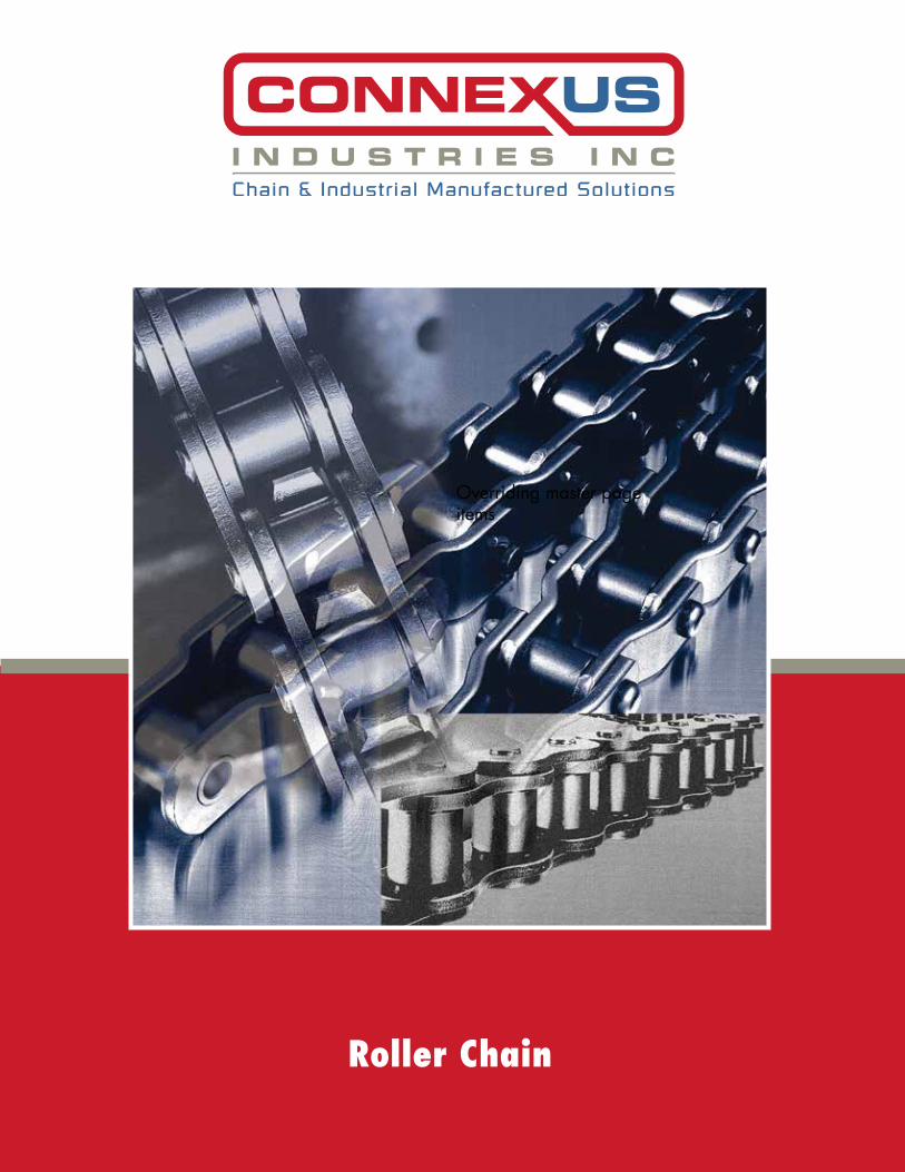
Roller Chain
Overriding master page items
2
INTRODUCTION
Chain & Industrial Manufactured Solutions
Connexus Industries Inc… Chain & Industrial Manufactured Solutions
Connexus Industries is a manufacturer and wholesaler of industrial steel chain and related products. A dynamic integration of four industry companies, Lacey Harmer, Viking Chains,I’Anco and Rens-Metal Shark has Connexus Industries positioned as one of the leading suppliers in our field.
Connexus Industries has 4 strategic stocking locations in North America, and distribution partners world wide. We can service any of our customer’s needs.
Connexus Industries has a diverse customer base that includes the wood, food packaging, cement, sugar, waste water and agricultural industries. By bringing our products to market through multiple channels We remain connected to our customers through contact with end users. As a manufacturer of specialty chains, attachments, sprockets and shaft asse mblies, our sales and engineering staff are able to recommend and assist our customers in their most difficult and arduous applications.
By displaying the registered CXS brand on all our products, and committed to the high standards of ISO quality management we assure our customers of our commitment and dedication to continuous product quality.
Cliff Lane
President CONNEXUS INDUSTRIES

3Chain & Industrial Manufactured Solutions
INDEX
4 Chains Construction & Components5 Standard Packaging & Ordering Information6 Standard Roller Chains 25 - 240-3 7 Heavy Duty Chains - H Series 25H - 160H-2 8 Heavy Duty Chains - SH Series 80SH - 200SH-3 9 Heavy Duty Chains - EX Series 80 EX - 240 EX-310 DuraLink - Platinum Series Roller Chain 60 DL - 240 DL11 RS Double Pitch Chains A2040 - A2060 12 Double Pitch Conveyor Chains C2040 - C2162H13 Straight Sidebar, Rollerless Chains 40F - 120F, 55 - 12514 Nickel Plated Standard Chains 25NP - 160NP15 Nickel Plated Double Pitch Chains C2040NP - C2160H NP16 Stainless Steel Standard Chains 25SS - 120SS17 Stainless Steel Double Pitch Chains C2040SS - C2082H SS18 Mega SS Standard Chains 40SS MEGA - 80-2SS MEGA19 Self Lube Chains 40SL - 80SL, C2040 SL - C2082H SL20 Hollow Pin Chains 40HP - 80HP, C2040 HP - C2082 HP21 Sidebow Chains 35SB - 60-SB22 British Standard Chains 05B - 48B-323 Leaf Chains - General Info24 Light Duty Leaf Chains AL422 - AL126625 Heavy Duty Leaf Chains BL423 - BL166626 Standard Roller Chains Attachments Parts Configuration27 Standard Roller Chains Attachments Attachment Spacing, Applications28 Standard Roller Chains Attachments 35 - 160 A-1, K-1, SA-1, SK-1, D-1, D-329 Standard Roller Chains Wide Contour Attachments 35 - 160 WA-1 - WSK-1, WA-2 - WSK-230 Mega Chains31 Mega Chains Standard Attachments 40SS - 80SS Mega A-1, K-1, SA-1, SK-132 Mega Chains Wide Contour Attachments 40SS - 80SS Mega - WA-1, WK-1, WSA-1, WSK-2
40SS - 80SS Mega WA-2, WK-2, WSA-2, WSK-233 Double Pitch Chains Attachments C2040 - C2082H A-1, K-1, SA-1, SK-1, D-1, D-334 Double Pitch Chains Attachments C2040 - C2082H A-2, K-2, SA-2, SK-235 Special Market Chains C2050 - C2060 Triple Speed36 Special Market Chains Citrus (C2060H D-5) Double Flex (DF3500)37 Wood Industry Chains Trimmer, Malleable, Combination Chains38 Chains Tools39 Engineering Data Chain Selection40 Engineering Data Chain Selection41 Engineering Data Chain Selection Chart42 Engineering Data Lubrication43 Chain Warning Statement, Terms and Conditions

4
IOS
Chain & Industrial Manufactured Solutions
CHAIN CONSTRUCTION & COMPONENTS
Roller Chain consists of pins, bushings, rollers and link plates as illustrated below
Pin requires high wear resistance and shearing strength to support the entire load acting on the chain
Bushing receives massive forces from other components of the chain and must provide wear resistance and fatigue strength
Roller requires high shock strength, collapse strength and wear resistance to protect the chain from heavy shock of the sprocket and also in order to articulate the chains smoothly when engaged with the sprocket
Link plate receives direct tension of the chain with occasional large shock on power transmission, therefore requires high tensile strength, shock resistance, and fatigue strength
Connecting Link(Spring Clip type)
Connecting Link(Cotter Pin type)
Connecting Link(Duplex)
Offset Link Offset Link(Duplex)
Two Pitch Offset Link
Connecting Link allows easy installation or removal of a roller chain with an even number of pitches. Spring Clips or Cotter Pins are used to retain the connecting pins.
Offset Link are used to adjust the lengths of the chain with an odd number of pitches. It is not recommended to use Offset Links. Whenever possible, use chain with an even number of pitches.
Two Pitch Offset Link is a combination of an inner link and offset link, which is stronger than One Pitch Offset Link.

5Chain & Industrial Manufactured Solutions
STANDARD PACKAGING & ORDERING INFO
STANDARD PACKAGING
Number of Links (Pitches) in Package
25 0.250 480 1200 2400 4800
35 0.375 320 800 1600 3200
40 0.500 240 600 1200 2400
41 0.500 240 600 1200 2400
50 0.625 192 480 960 1920
60 0.750 160 400 800 1600
80 1.000 120 300 600
100 1.250 96 240 480
120 1.500 80
140 1.750 68
160 2.000 60
180 2.250 54
200 2.500 48
240 3.000 40
Chain
Size
Chain
Pitch
Standard
10’ Box 25’ Reel
Standard Reels
50’ Reel 100’ Reel
10’ Box Normal stocking of roller chain will be in 10’ Box with proper product identification.
Reel or Coil Available in coils or reels, coiled around wooden or wire spool, normally 25’, 50’ or 100’ depending on size of chain and weight.
Ordering Cut to Length Strands: If length in pitches required is known. Please call our service personnel for aid in ordering if only length in inches, feet, or metric length is known
Advise Configuration
Terms Description of Assembly
RLEEOdd No. of Pitches
Inc Conn Link (Master Link)Each End
Even No. of Pitches
Roller Link each end exact amount of links (pitches) will end with roller link each end of strand,
no connecting link or offset link will be supplied
Pitches including connecting link exact amount of links (pitches) will include a loose connecting link (master link) at the end of strand
Pitches including connecting link each end exact amount of links (pitches) will include a loose connecting link (master link)
at both ends of strand
Pitches including connecting link (master link) assembled endlessexact amount of links (pitches) will include conn link assembled into endless loop
Pitches riveted endlessexact amount of links (pitches) will be supplied with no connecting or offset link but will be riveted into
endless loop using riveted pin link and roller link within the chain
Pitches including connecting link (master link) and offset link exact amount of pitches ordered will include an offset link assembled onto chain and a loose
connecting link (master link) will be supplied
Inc Conn Link (Master Link)Even No. of Pitches
Inc Conn Link ( Master Link)Assembled EndlessEven No. of Pitches
Riveted EndlessEven No. of Pitches
Inc C/L & O/LOdd No. of Pitches
6 Chain & Industrial Manufactured Solutions
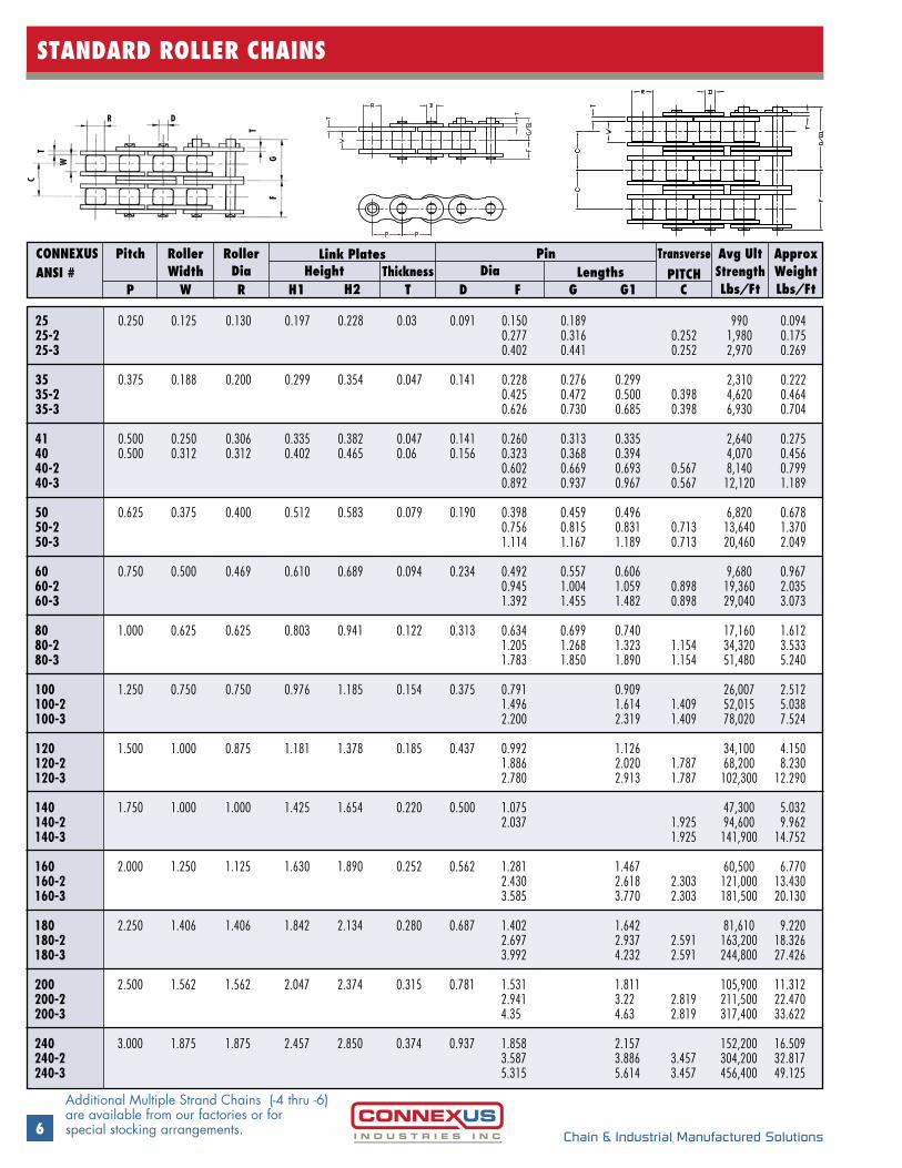
STANDARD ROLLER CHAINS
CONNEXUSANSI #
RollerWidth Height
RollerDia
TransversePITCH
Avg UltStrengthLbs/Ft
Approx WeightLbs/Ft
Dia LengthsLink Plates PinPitch
ThicknessP W R H1 H2 T D F G G1 C
R D
T
W
T
C
GF
25 0.250 0.125 0.130 0.197 0.228 0.03 0.091 0.150 0.189 990 0.094 25-2 0.277 0.316 0.252 1,980 0.175 25-3 0.402 0.441 0.252 2,970 0.269 35 0.375 0.188 0.200 0.299 0.354 0.047 0.141 0.228 0.276 0.299 2,310 0.222 35-2 0.425 0.472 0.500 0.398 4,620 0.464 35-3 0.626 0.730 0.685 0.398 6,930 0.704 41 0.500 0.250 0.306 0.335 0.382 0.047 0.141 0.260 0.313 0.335 2,640 0.275 40 0.500 0.312 0.312 0.402 0.465 0.06 0.156 0.323 0.368 0.394 4,070 0.456 40-2 0.602 0.669 0.693 0.567 8,140 0.799 40-3 0.892 0.937 0.967 0.567 12,120 1.189 50 0.625 0.375 0.400 0.512 0.583 0.079 0.190 0.398 0.459 0.496 6,820 0.678 50-2 0.756 0.815 0.831 0.713 13,640 1.370 50-3 1.114 1.167 1.189 0.713 20,460 2.049 60 0.750 0.500 0.469 0.610 0.689 0.094 0.234 0.492 0.557 0.606 9,680 0.967 60-2 0.945 1.004 1.059 0.898 19,360 2.035 60-3 1.392 1.455 1.482 0.898 29,040 3.073 80 1.000 0.625 0.625 0.803 0.941 0.122 0.313 0.634 0.699 0.740 17,160 1.612 80-2 1.205 1.268 1.323 1.154 34,320 3.533 80-3 1.783 1.850 1.890 1.154 51,480 5.240 100 1.250 0.750 0.750 0.976 1.185 0.154 0.375 0.791 0.909 26,007 2.512 100-2 1.496 1.614 1.409 52,015 5.038 100-3 2.200 2.319 1.409 78,020 7.524 120 1.500 1.000 0.875 1.181 1.378 0.185 0.437 0.992 1.126 34,100 4.150 120-2 1.886 2.020 1.787 68,200 8.230 120-3 2.780 2.913 1.787 102,300 12.290 140 1.750 1.000 1.000 1.425 1.654 0.220 0.500 1.075 47,300 5.032 140-2 2.037 1.925 94,600 9.962 140-3 1.925 141,900 14.752 160 2.000 1.250 1.125 1.630 1.890 0.252 0.562 1.281 1.467 60,500 6.770 160-2 2.430 2.618 2.303 121,000 13.430 160-3 3.585 3.770 2.303 181,500 20.130 180 2.250 1.406 1.406 1.842 2.134 0.280 0.687 1.402 1.642 81,610 9.220 180-2 2.697 2.937 2.591 163,200 18.326 180-3 3.992 4.232 2.591 244,800 27.426 200 2.500 1.562 1.562 2.047 2.374 0.315 0.781 1.531 1.811 105,900 11.312 200-2 2.941 3.22 2.819 211,500 22.470 200-3 4.35 4.63 2.819 317,400 33.622 240 3.000 1.875 1.875 2.457 2.850 0.374 0.937 1.858 2.157 152,200 16.509 240-2 3.587 3.886 3.457 304,200 32.817 240-3 5.315 5.614 3.457 456,400 49.125
Additional Multiple Strand Chains (-4 thru -6) are available from our factories or for special stocking arrangements.

7Chain & Industrial Manufactured Solutions
HEAVY DUTY CHAINS HEAVY SERIES
CONNEXUSANSI #
RollerWidth
RollerDia
TransversePITCH
Avg UltStrengthLbs/Ft
Approx WeightLbs/Ft
Dia LengthsHeightLink Plates PinPitch
ThicknessP W R H1 H2 T D F G G1 C
25-H 0.250 0.125 0.130 0.197 0.228 0.039 0.090 0.177 0.200 1,232 0.11415-H 0.500 0.188 0.306 0.402 0.465 0.059 0.156 0.252 0.307 4,070 0.34 50H 0.625 0.375 0.400 0.512 0.583 0.094 0.199 0.429 0.488 0.508 6,820 0.75 60H 0.750 0.500 0.469 0.610 0.689 0.122 0.234 0.555 0.618 0.654 9,680 1.2160H-2 1.070 1.134 1.169 1.028 19,360 2.39 80H 1.000 0.625 0.625 0.819 0.945 0.154 0.313 0.705 0.819 17,600 1.9880H-2 1.346 1.461 1.283 35,200 3.92 100H 1.250 0.750 0.750 0.976 1.185 0.185 0.375 0.854 0.980 26,400 2.98100H-2 1.624 1.750 1.539 52,800 5.59 120H 1.500 1.000 0.875 1.180 1.378 0.220 0.437 1.062 1.204 35,200 4.55120H-2 2.024 2.167 1.925 70,400 9.02 140H 1.750 1.000 1.000 1.430 1.654 0.252 0.500 1.138 1.303 47,300 5.44140H-2 2.171 2.325 2.055 94,600 10.80 160H 2.000 1.250 1.125 1.630 1.890 0.283 0.562 1.344 1.530 60,500 7.29160H-2 2.563 2.748 2.437 121,000 13.98
• ANSI Heavy Series Chains differ from standard roller chains in the extra thickness of link plates
• The thicker plates provide greater shock load resistance and fatigue strength
t These chains are used in heavy duty applications
R D
T
W
T
C
GF
H2 H1
P P
8 Chain & Industrial Manufactured Solutions
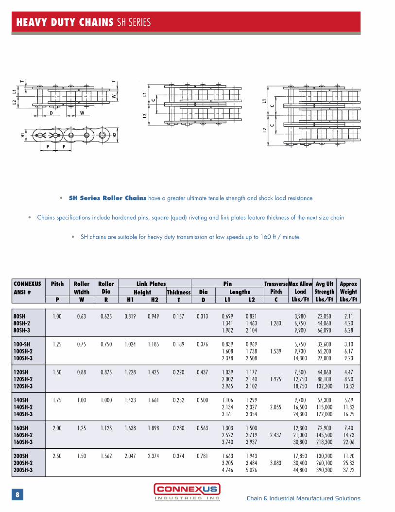
HEAVY DUTY CHAINS SH SERIES
80SH 1.00 0.63 0.625 0.819 0.949 0.157 0.313 0.699 0.821 3,980 22,050 2.1180SH-2 1.341 1.463 1.283 6,750 44,060 4.2080SH-3 1.982 2.104 9,900 66,090 6.28 100-SH 1.25 0.75 0.750 1.024 1.185 0.189 0.376 0.839 0.969 5,750 32,600 3.10100SH-2 1.608 1.738 1.539 9,730 65,200 6.17100SH-3 2.378 2.508 14,300 97,800 9.23 120SH 1.50 0.88 0.875 1.228 1.425 0.220 0.437 1.039 1.177 7,500 44,060 4.47120SH-2 2.002 2.140 1.925 12,750 88,100 8.90120SH-3 2.965 3.102 18,750 132,200 13.32 140SH 1.75 1.00 1.000 1.433 1.661 0.252 0.500 1.106 1.299 9,700 57,300 5.69140SH-2 2.134 2.327 2.055 16,500 115,000 11.32140SH-3 3.161 3.354 24,300 172,000 16.95 160SH 2.00 1.25 1.125 1.638 1.898 0.280 0.563 1.303 1.500 12,300 72,900 7.40160SH-2 2.522 2.719 2.437 21,000 145,500 14.73160SH-3 3.740 3.937 30,800 218,300 22.06 200SH 2.50 1.50 1.562 2.047 2.374 0.374 0.781 1.663 1.943 17,850 130,200 11.90 200SH-2 3.205 3.484 3.083 30,400 260,100 25.33200SH-3 4.746 5.026 44,800 390,300 37.92
• SH Series Roller Chains have a greater ultimate tensile strength and shock load resistance
• Chains specifications include hardened pins, square (quad) riveting and link plates feature thickness of the next size chain
• SH chains are suitable for heavy duty transmission at low speeds up to 160 ft / minute.
CONNEXUSANSI #
RollerWidth
RollerDia
Max AllowLoad
Lbs/Ft
TransversePitch
Avg UltStrengthLbs/Ft
ApproxWeightLbs/Ft
Dia LengthsHeightLink Plates PinPitch
ThicknessP W R H1 H2 T D L1 L2 C
9Chain & Industrial Manufactured Solutions
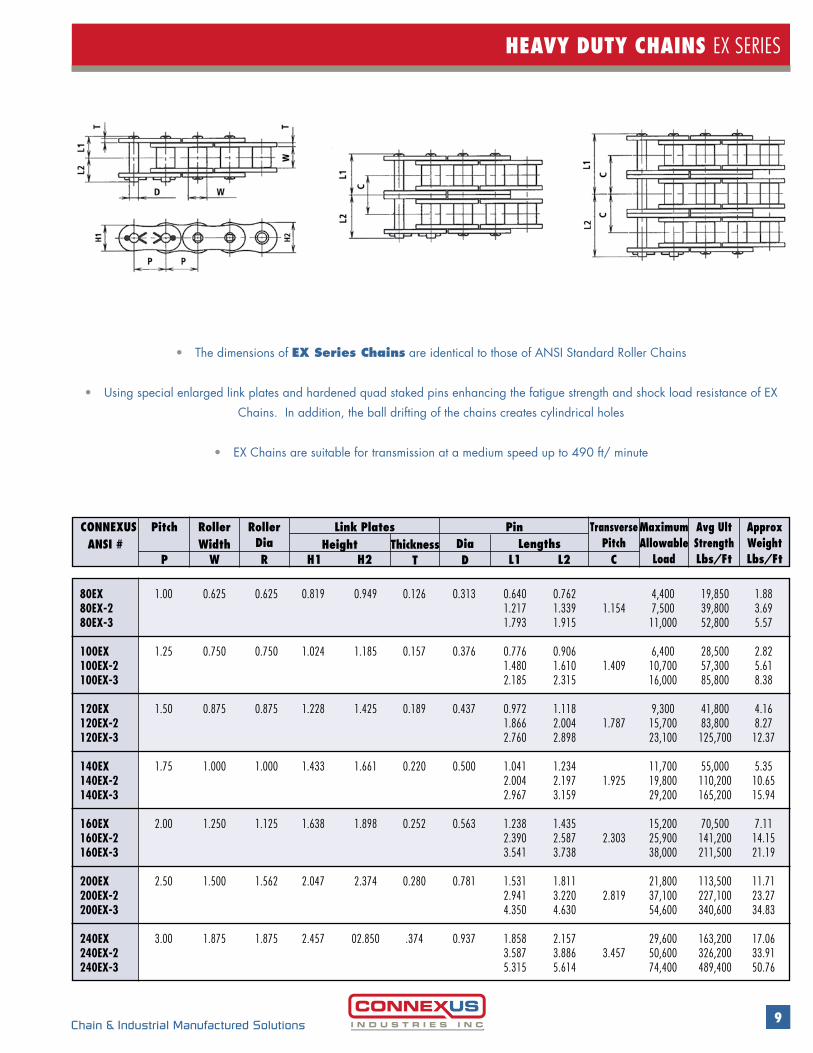
HEAVY DUTY CHAINS EX SERIES
• The dimensions of EX Series Chains are identical to those of ANSI Standard Roller Chains
• Using special enlarged link plates and hardened quad staked pins enhancing the fatigue strength and shock load resistance of EX Chains. In addition, the ball drifting of the chains creates cylindrical holes
• EX Chains are suitable for transmission at a medium speed up to 490 ft/ minute
80EX 1.00 0.625 0.625 0.819 0.949 0.126 0.313 0.640 0.762 4,400 19,850 1.8880EX-2 1.217 1.339 1.154 7,500 39,800 3.6980EX-3 1.793 1.915 11,000 52,800 5.57 100EX 1.25 0.750 0.750 1.024 1.185 0.157 0.376 0.776 0.906 6,400 28,500 2.82100EX-2 1.480 1.610 1.409 10,700 57,300 5.61100EX-3 2.185 2.315 16,000 85,800 8.38 120EX 1.50 0.875 0.875 1.228 1.425 0.189 0.437 0.972 1.118 9,300 41,800 4.16120EX-2 1.866 2.004 1.787 15,700 83,800 8.27120EX-3 2.760 2.898 23,100 125,700 12.37 140EX 1.75 1.000 1.000 1.433 1.661 0.220 0.500 1.041 1.234 11,700 55,000 5.35140EX-2 2.004 2.197 1.925 19,800 110,200 10.65140EX-3 2.967 3.159 29,200 165,200 15.94 160EX 2.00 1.250 1.125 1.638 1.898 0.252 0.563 1.238 1.435 15,200 70,500 7.11160EX-2 2.390 2.587 2.303 25,900 141,200 14.15160EX-3 3.541 3.738 38,000 211,500 21.19 200EX 2.50 1.500 1.562 2.047 2.374 0.280 0.781 1.531 1.811 21,800 113,500 11.71200EX-2 2.941 3.220 2.819 37,100 227,100 23.27200EX-3 4.350 4.630 54,600 340,600 34.83 240EX 3.00 1.875 1.875 2.457 02.850 .374 0.937 1.858 2.157 29,600 163,200 17.06240EX-2 3.587 3.886 3.457 50,600 326,200 33.91240EX-3 5.315 5.614 74,400 489,400 50.76
CONNEXUS ANSI #
RollerWidth
RollerDia
MaximumAllowable
Load
TransversePitch
Avg UltStrengthLbs/Ft
ApproxWeightLbs/Ft
Dia LengthsHeightLink Plates PinPitch
ThicknessP W R H1 H2 T D L1 L2 C

10 Chain & Industrial Manufactured Solutions
DURA LINK - PLATINUM SERIES ROLLER CHAIN
• Wide waist designed side plates for greater fatigue resistance
• Manufactured with Solid Bushings, Solid Rollers and Through Hardened Pins
• Greater maximum allowable load than standard roller chain
• For applications that have high speed and high shock loads
60 0.750 0.500 0.469 0.610 0.689 0.094 0.234 0.492 0.557 0.606 10,648 0.967 60-2 0.945 1.004 1.059 0.898 21,296 2.035 80 1.000 0.625 0.625 0.803 0.941 0.122 0.313 0.634 0.699 0.740 18,876 1.612 80-2 1.205 1.268 1.323 1.154 37,620 3.533 100 1.250 0.750 0.750 0.976 1.185 0.154 0.375 0.791 0.909 28,607 2.512 100-2 1.496 1.614 1.409 57,216 5.038 120 1.500 1.000 0.875 1.181 1.378 0.185 0.437 0.992 1.126 37,510 4.150 120-2 1.886 2.020 1.787 75,020 8.230 140 1.750 1.000 1.000 1.425 1.654 0.220 0.500 1.075 52,030 5.032 140-2 2.037 1.925 104,060 9.962 160 2.000 1.250 1.125 1.630 1.890 0.252 0.562 1.281 1.467 66,500 6.770 160-2 2.430 2.618 2.303 133,100 13.430 160-3 3.585 3.770 2.303 199,650 20.130 180 2.250 1.406 1.406 1.842 2.134 0.280 0.687 1.402 1.642 89,771 9.220 180-2 2.697 2.937 2.591 179,520 18.326 180-3 3.992 4.232 2.591 269,280 27.426 200 2.500 1.562 1.562 2.047 2.374 0.315 0.781 1.531 1.811 116,490 11.312 200-2 2.941 3.22 2.819 232,650 22.470 200-3 4.35 4.63 2.819 349,140 33.622 240 3.000 1.875 1.875 2.457 2.850 0.374 0.937 1.858 2.157 167,420 16.509 240-2 3.587 3.886 3.457 334,620 32.817 240-3 5.315 5.614 3.457 502,040 49.125
CONNEXUSANSI #
RollerWidth Height
RollerDia
TransversePITCH
Avg UltStrengthLbs/Ft
Approx WeightLbs/Ft
Dia LengthsLink Plates PinPitch
ThicknessP W R H1 H2 T D F G G1 C
11Chain & Industrial Manufactured Solutions
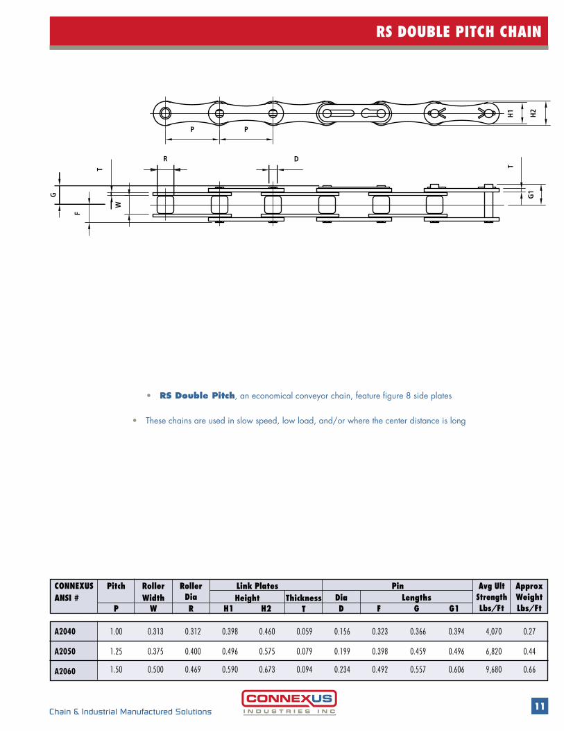
RS DOUBLE PITCH CHAIN
CONNEXUSANSI #
RollerWidth
RollerDia
Avg UltStrengthLbs/Ft
Approx WeightLbs/Ft
Dia LengthsHeightLink Plates PinPitch
ThicknessP W R H1 H2 T D F G G1
• RS Double Pitch, an economical conveyor chain, feature figure 8 side plates
• These chains are used in slow speed, low load, and/or where the center distance is long
A2040 1.00 0.313 0.312 0.398 0.460 0.059 0.156 0.323 0.366 0.394 4,070 0.27
A2050 1.25 0.375 0.400 0.496 0.575 0.079 0.199 0.398 0.459 0.496 6,820 0.44
A2060 1.50 0.500 0.469 0.590 0.673 0.094 0.234 0.492 0.557 0.606 9,680 0.66
F
G
R
W
T
PP
D
H2
G1
TH
1
12 Chain & Industrial Manufactured Solutions
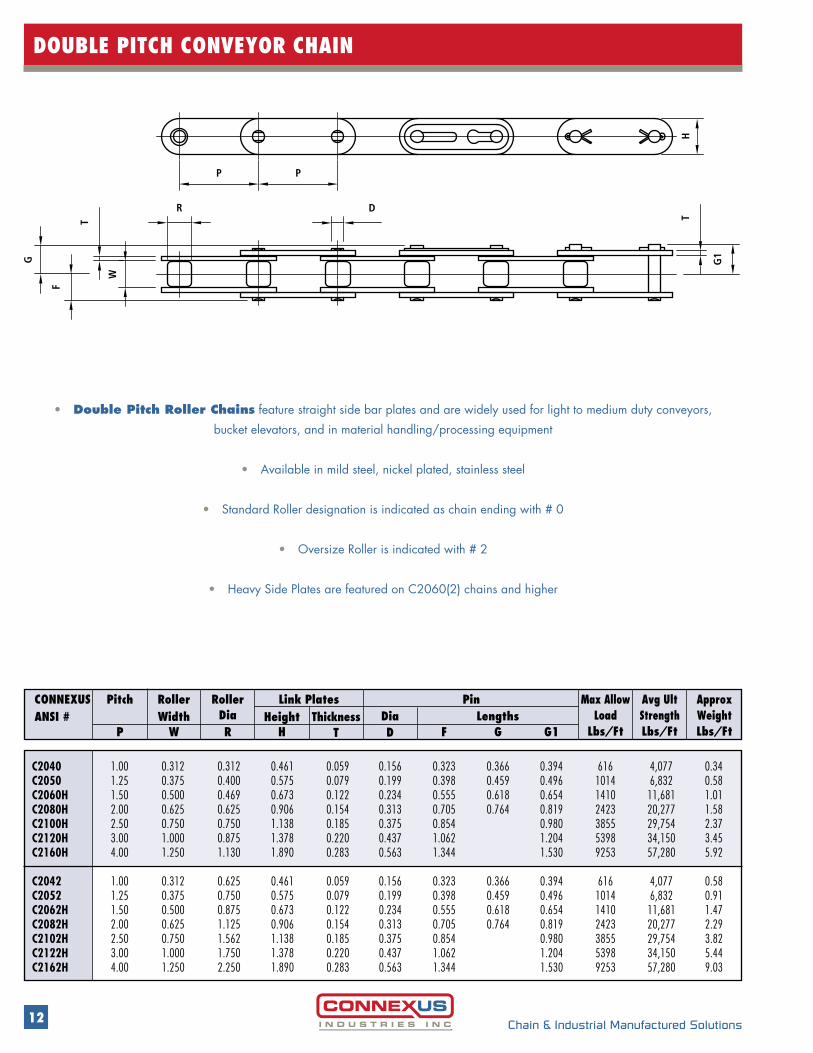
DOUBLE PITCH CONVEYOR CHAIN
• Double Pitch Roller Chains feature straight side bar plates and are widely used for light to medium duty conveyors, bucket elevators, and in material handling/processing equipment
• Available in mild steel, nickel plated, stainless steel
• Standard Roller designation is indicated as chain ending with # 0
• Oversize Roller is indicated with # 2
• Heavy Side Plates are featured on C2060(2) chains and higher
C2040 1.00 0.312 0.312 0.461 0.059 0.156 0.323 0.366 0.394 616 4,077 0.34C2050 1.25 0.375 0.400 0.575 0.079 0.199 0.398 0.459 0.496 1014 6,832 0.58C2060H 1.50 0.500 0.469 0.673 0.122 0.234 0.555 0.618 0.654 1410 11,681 1.01C2080H 2.00 0.625 0.625 0.906 0.154 0.313 0.705 0.764 0.819 2423 20,277 1.58C2100H 2.50 0.750 0.750 1.138 0.185 0.375 0.854 0.980 3855 29,754 2.37C2120H 3.00 1.000 0.875 1.378 0.220 0.437 1.062 1.204 5398 34,150 3.45C2160H 4.00 1.250 1.130 1.890 0.283 0.563 1.344 1.530 9253 57,280 5.92 C2042 1.00 0.312 0.625 0.461 0.059 0.156 0.323 0.366 0.394 616 4,077 0.58C2052 1.25 0.375 0.750 0.575 0.079 0.199 0.398 0.459 0.496 1014 6,832 0.91C2062H 1.50 0.500 0.875 0.673 0.122 0.234 0.555 0.618 0.654 1410 11,681 1.47C2082H 2.00 0.625 1.125 0.906 0.154 0.313 0.705 0.764 0.819 2423 20,277 2.29C2102H 2.50 0.750 1.562 1.138 0.185 0.375 0.854 0.980 3855 29,754 3.82C2122H 3.00 1.000 1.750 1.378 0.220 0.437 1.062 1.204 5398 34,150 5.44C2162H 4.00 1.250 2.250 1.890 0.283 0.563 1.344 1.530 9253 57,280 9.03
CONNEXUSANSI #
RollerWidth
RollerDia
Max AllowLoad
Lbs/Ft
Avg UltStrengthLbs/Ft
ApproxWeightLbs/Ft
Dia LengthsHeightLink Plates PinPitch
ThicknessP W R H T D F G G1
G
F
R
T
W
PP
D
HT
G1

13Chain & Industrial Manufactured Solutions
STRAIGHT SIDEBAR/ROLLERLESS CHAIN
• Straight Sidebar Roller Chains
• Rollerless Chains, having the same tensile strength and working loads as ANSI standard chains, are used in lift or hoist applications
• They require special sprockets and off-set links are not recommended in these applications
55 0.625 0.375 0.276 0.512 0.583 0.079 0.199 0.398 0.459 0.496 6,820 0.56
65 0.750 0.500 0.319 0.610 0.689 0.094 0.234 0.492 0.557 0.606 9,680 0.80
85 1.000 0.625 0.445 0.803 0.941 0.122 0.313 0.634 0.699 0.740 17,160 1.48
105 1.250 0.750 0.530 0.976 1.185 0.154 0.375 0.791 0.864 0.909 25,960 2.21
125 1.500 1.000 0.624 1.181 1.378 0.185 0.437 0.972 1.110 1.126 34,100 3.23
CONNEXUSANSI #
RollerWidth
BushingDia
Avg UltStrengthLbs/Ft
Approx WeightLbs/Ft
Dia LengthsHeightLink Plates PinPitch
ThicknessP W R H1 H2 T D F G G1
40-F 0.500 0.313 0.312 0.472 0.059 0.156 0.323 0.368 0.394 4,100 0.44
50-F 0.625 0.375 0.400 0.591 0.079 0.199 0.398 0.459 0.496 6,800 0.69
60-F 0.750 0.500 0.469 0.713 0.094 0.234 0.492 0.557 0.606 9,700 0.98
80-F 1.000 0.625 0.625 0.945 0.122 0.313 0.634 0.699 0.740 17,160 1.64
100-F 1.250 0.750 0.750 1.138 0.154 0.375 0.791 0.864 0.909 28,600 2.88
120-F 1.500 1.000 0.875 1.425 0.189 0.437 0.972 1.110 1.126 34,200 4.01
CONNEXUSANSI #
RollerWidth
RollerDia
Avg UltStrengthLbs/Ft
Approx WeightLbs/Ft
Dia LengthsHeightLink Plates PinPitch
ThicknessP W R H T D F G1G
P
R
T
WH
D
P
F
T
G1G
G1
P
H1
T
W
H2
P
D
GF
T
R
14 Chain & Industrial Manufactured Solutions
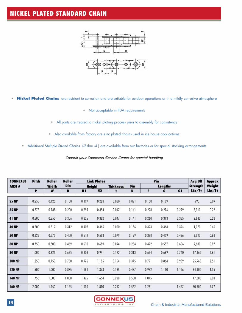
NICKEL PLATED STANDARD CHAIN
• Nickel Plated Chains are resistant to corrosion and are suitable for outdoor operations or in a mildly corrosive atmosphere
• Not acceptable in FDA requirements
• All parts are treated to nickel plating process prior to assembly for consistency
• Also available from factory are zinc plated chains used in ice house applications
• Additional Multiple Strand Chains (-2 thru -4 ) are available from our factories or for special stocking arrangements
Consult your Connexus Service Center for special handling
25 NP 0.250 0.125 0.130 0.197 0.228 0.030 0.091 0.150 0.189 990 0.09
35 NP 0.375 0.188 0.200 0.299 0.354 0.047 0.141 0.228 0.276 0.299 2,310 0.22
41 NP 0.500 0.250 0.306 0.335 0.382 0.047 0.141 0.260 0.313 0.335 2,640 0.28
40 NP 0.500 0.312 0.312 0.402 0.465 0.060 0.156 0.323 0.368 0.394 4,070 0.46
50 NP 0.625 0.375 0.400 0.512 0.583 0.079 0.199 0.398 0.459 0.496 6,820 0.68
60 NP 0.750 0.500 0.469 0.610 0.689 0.094 0.234 0.492 0.557 0.606 9,680 0.97
80 NP 1.000 0.625 0.625 0.803 0.941 0.122 0.313 0.634 0.699 0.740 17,160 1.61
100 NP 1.250 0.750 0.750 0.976 1.185 0.154 0.375 0.791 0.864 0.909 25,960 2.51
120 NP 1.500 1.000 0.875 1.181 1.378 0.185 0.437 0.972 1.110 1.126 34,100 4.15
140 NP 1.750 1.000 1.000 1.425 1.654 0.220 0.500 1.075 47,300 5.03
160 NP 2.000 1.250 1.125 1.630 1.890 0.252 0.562 1.281 1.467 60,500 6.77
CONNEXUSANSI #
RollerWidth
RollerDia
Avg UltStrengthLbs/Ft
Approx WeightLbs/Ft
Dia LengthsHeightLink Plates PinPitch
ThicknessP W R H1 H2 T D F G G1
15Chain & Industrial Manufactured Solutions
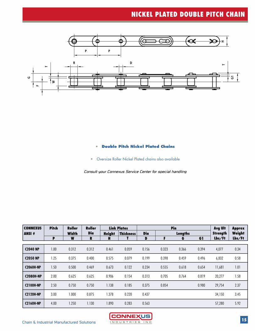
NICKEL PLATED DOUBLE PITCH CHAIN
CONNEXUSANSI #
RollerWidth
RollerDia
Approx WeightLbs/Ft
Avg UltStrengthLbs/Ft
Dia LengthsHeightLink Plates PinPitch
ThicknessP W R H T D F G G1
• Double Pitch Nickel Plated Chains
• Oversize Roller Nickel Plated chains also available
Consult your Connexus Service Center for special handling
C2040 NP 1.00 0.312 0.312 0.461 0.059 0.156 0.323 0.366 0.394 4,077 0.34
C2050 NP 1.25 0.375 0.400 0.575 0.079 0.199 0.398 0.459 0.496 6,832 0.58
C2060H-NP 1.50 0.500 0.469 0.673 0.122 0.234 0.555 0.618 0.654 11,681 1.01
C2080H-NP 2.00 0.625 0.625 0.906 0.154 0.313 0.705 0.764 0.819 20,277 1.58
C2100H-NP 2.50 0.750 0.750 1.138 0.185 0.375 0.854 0.980 29,754 2.37
C2120H-NP 3.00 1.000 0.875 1.378 0.220 0.437 34,150 3.45
C2160H-NP 4.00 1.250 1.130 1.890 0.283 0.563 57,280 5.92
G
F
R
T
WPP
D
H T
G1
16 Chain & Industrial Manufactured Solutions
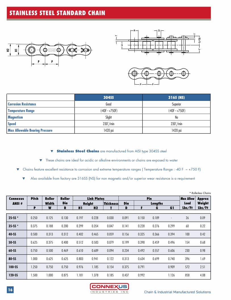
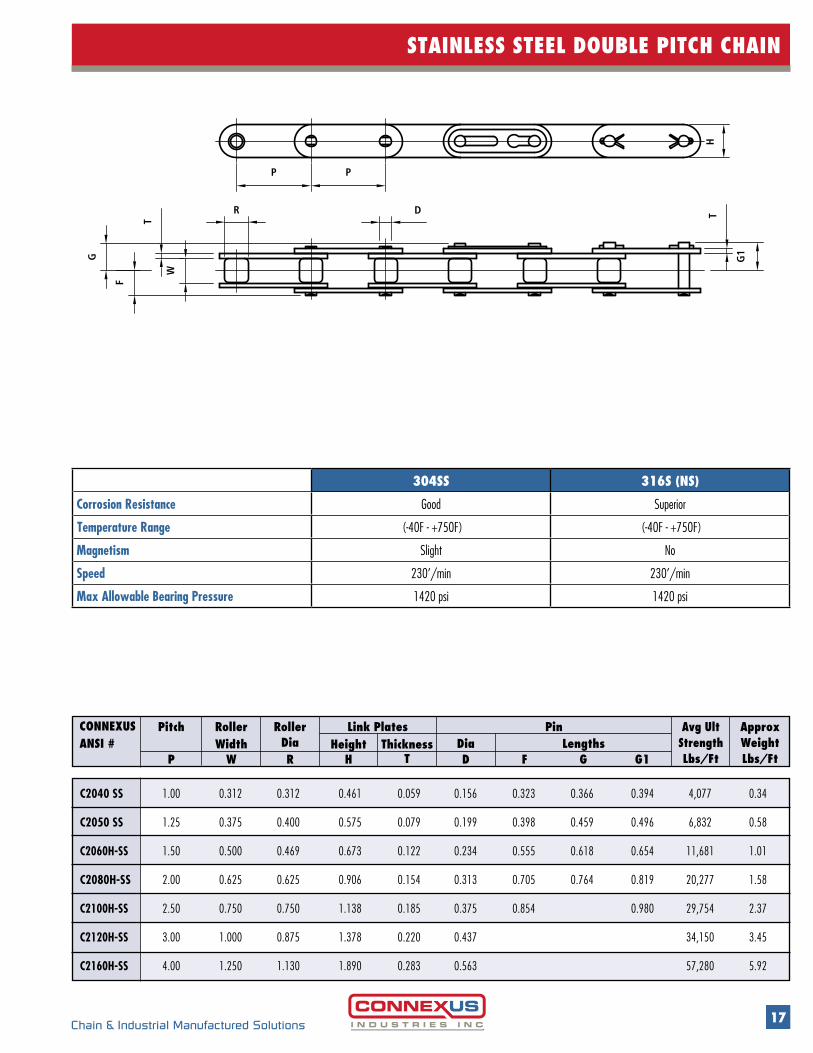
STAINLESS STEEL STANDARD CHAIN
t Stainless Steel Chains are manufactured from AISI type 304SS steel
t These chains are ideal for acidic or alkaline environments or chains are exposed to water
t Chains feature excellent resistance to corrosion and extreme temperature ranges ( Temperature Range : -40 F ~ +750 F)
t Also available from factory are 316SS (NS) for non magnetic and/or superior wear resistance is a requirement
* Rollerless Chains
Connexus ANSI #
RollerWidth
RollerDia
Max Allow Load
Lbs/Ft
Approx WeightLbs/Ft
Dia LengthsHeightLink Plates PinPitch
ThicknessP W R H1 H2 T D F G G1
H2 H1
P P
304SS 316S (NS)
Corrosion Resistance Good Superior
Temperature Range (-40F - +750F) (-40F - +750F)
Magnetism Slight No
Speed 230’/min 230’/min
Max Allowable Bearing Pressure 1420 psi 1420 psi
25-SS * 0.250 0.125 0.130 0.197 0.228 0.030 0.091 0.150 0.189 - 26 0.09
35-SS * 0.375 0.188 0.200 0.299 0.354 0.047 0.141 0.228 0.276 0.299 60 0.22
40-SS 0.500 0.313 0.312 0.402 0.465 0.059 0.156 0.325 0.366 0.394 100 0.42
50-SS 0.625 0.375 0.400 0.512 0.583 0.079 0.199 0.398 0.459 0.496 154 0.68
60-SS 0.750 0.500 0.469 0.610 0.689 0.094 0.234 0.492 0.557 0.606 230 0.98
80-SS 1.000 0.625 0.625 0.803 0.941 0.122 0.313 0.634 0.699 0.740 396 1.69
100-SS 1.250 0.750 0.750 0.976 1.185 0.154 0.375 0.791 0.909 572 2.51
120-SS 1.500 1.000 0.875 1.181 1.378 0.185 0.437 0.992 1.126 858 4.08
17Chain & Industrial Manufactured Solutions
STAINLESS STEEL DOUBLE PITCH CHAIN
CONNEXUS ANSI #
RollerWidth
RollerDia
Approx WeightLbs/Ft
Avg UltStrengthLbs/Ft
Dia LengthsHeightLink Plates PinPitch
ThicknessP W R H T D F G G1
C2040 SS 1.00 0.312 0.312 0.461 0.059 0.156 0.323 0.366 0.394 4,077 0.34
C2050 SS 1.25 0.375 0.400 0.575 0.079 0.199 0.398 0.459 0.496 6,832 0.58
C2060H-SS 1.50 0.500 0.469 0.673 0.122 0.234 0.555 0.618 0.654 11,681 1.01
C2080H-SS 2.00 0.625 0.625 0.906 0.154 0.313 0.705 0.764 0.819 20,277 1.58
C2100H-SS 2.50 0.750 0.750 1.138 0.185 0.375 0.854 0.980 29,754 2.37
C2120H-SS 3.00 1.000 0.875 1.378 0.220 0.437 34,150 3.45
C2160H-SS 4.00 1.250 1.130 1.890 0.283 0.563 57,280 5.92
G
F
R
T
WPP
D
H T
G1
304SS 316S (NS)
Corrosion Resistance Good Superior
Temperature Range (-40F - +750F) (-40F - +750F)
Magnetism Slight No
Speed 230’/min 230’/min
Max Allowable Bearing Pressure 1420 psi 1420 psi
18 Chain & Industrial Manufactured Solutions
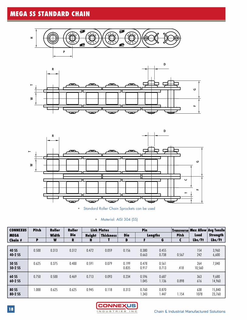
MEGA SS STANDARD CHAIN
• Standard Roller Chain Sprockets can be used
• Material: AISI 304 (SS)
CONNEXUS MEGA Chain #
RollerWidth
RollerDia
Avg TensileStrengthLbs/Ft
Max Allow Load
Lbs/FtDia LengthsHeight
Link Plates PinPitchThickness
P W R H T D F G C
TransversePitch
40 SS 0.500 0.313 0.312 0.472 0.059 0.156 0.380 0.455 154 3,960 40-2 SS 0.663 0.738 0.567 242 6,600 50 SS 0.625 0.375 0.400 0.591 0.079 0.199 0.478 0.561 264 7,040 50-2 SS 0.835 0.917 0.713 .418 10,560 60 SS 0.750 0.500 0.469 0.713 0.093 0.234 0.596 0.687 363 9,68060-2 SS 1.045 1.136 0.898 616 14,960 80 SS 1.000 0.625 0.625 0.945 0.118 0.313 0.760 0.870 638 15,84080-2 SS 1.343 1.447 1.154 1078 23,760
P
G
S
H
M
04
E A
S
G
S
M
04
E A
S
G
S
M
40
E A
S
M
40
E A
SS
G
TW
T
FG
C
GF
T
W
R
R
D
D
19Chain & Industrial Manufactured Solutions
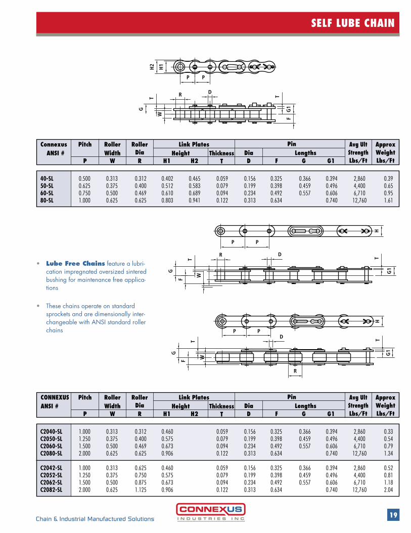
SELF LUBE CHAIN
• Lube Free Chains feature a lubri-cation impregnated oversized sintered bushing for maintenance free applica-tions
• These chains operate on standard sprockets and are dimensionally inter-changeable with ANSI standard roller chains
C2040-SL 1.000 0.313 0.312 0.460 0.059 0.156 0.325 0.366 0.394 2,860 0.33C2050-SL 1.250 0.375 0.400 0.575 0.079 0.199 0.398 0.459 0.496 4,400 0.54C2060-SL 1.500 0.500 0.469 0.673 0.094 0.234 0.492 0.557 0.606 6,710 0.79C2080-SL 2.000 0.625 0.625 0.906 0.122 0.313 0.634 0.740 12,760 1.34 C2042-SL 1.000 0.313 0.625 0.460 0.059 0.156 0.325 0.366 0.394 2,860 0.52C2052-SL 1.250 0.375 0.750 0.575 0.079 0.199 0.398 0.459 0.496 4,400 0.81C2062-SL 1.500 0.500 0.875 0.673 0.094 0.234 0.492 0.557 0.606 6,710 1.18C2082-SL 2.000 0.625 1.125 0.906 0.122 0.313 0.634 0.740 12,760 2.04
CONNEXUS ANSI #
RollerWidth
RollerDia
Avg UltStrengthLbs/Ft
Approx WeightLbs/Ft
Dia LengthsHeightLink Plates PinPitch
ThicknessP W R H1 H2 T D F G G1
40-SL 0.500 0.313 0.312 0.402 0.465 0.059 0.156 0.325 0.366 0.394 2,860 0.3950-SL 0.625 0.375 0.400 0.512 0.583 0.079 0.199 0.398 0.459 0.496 4,400 0.6560-SL 0.750 0.500 0.469 0.610 0.689 0.094 0.234 0.492 0.557 0.606 6,710 0.9580-SL 1.000 0.625 0.625 0.803 0.941 0.122 0.313 0.634 0.740 12,760 1.61
Connexus ANSI #
RollerWidth
RollerDia
Avg UltStrengthLbs/Ft
Approx WeightLbs/Ft
Dia LengthsHeightLink Plates PinPitch
ThicknessP W R H1 H2 T D F G G1
D
T
WH
1
P
H2
P
T
G1
F
R
G
G
F
R
T
PP
HT
G1
D
WT
PPD
HT
G1
F
G
R
W
20 Chain & Industrial Manufactured Solutions
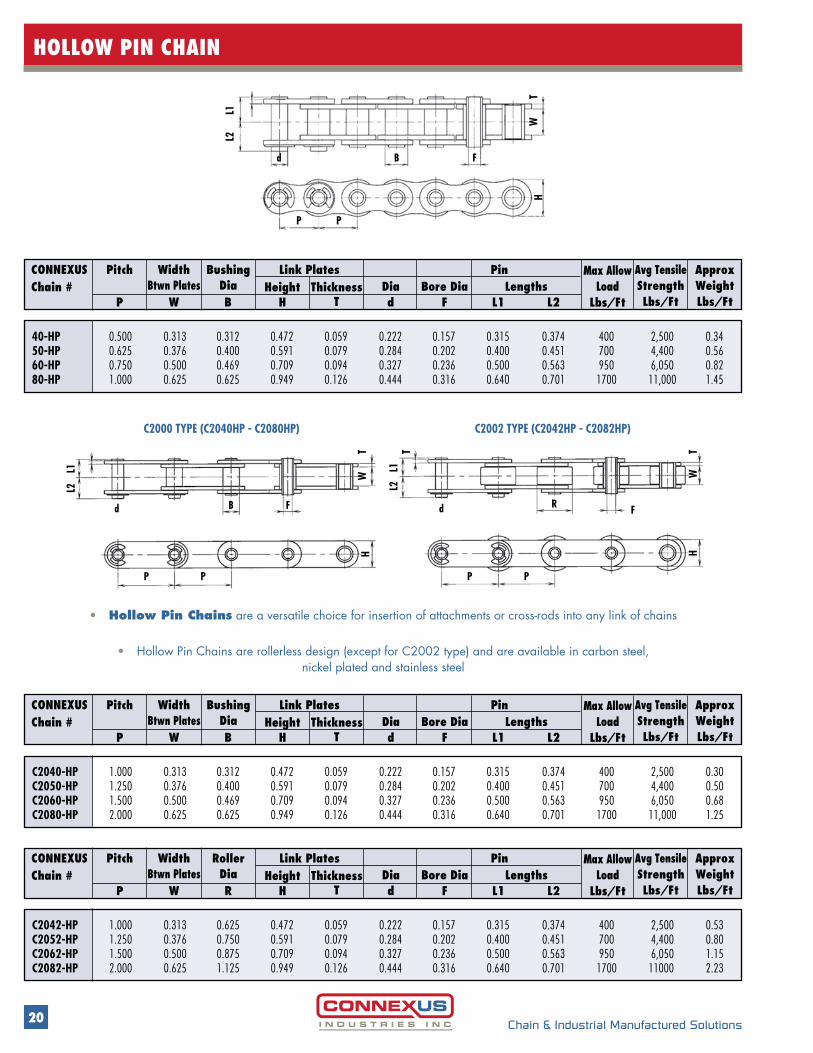
HOLLOW PIN CHAIN
CONNEXUS Chain #
WidthBtwn Plates
RollerDia
Approx WeightLbs/Ft
Avg TensileStrengthLbs/Ft
Dia Bore Dia LengthsHeightLink Plates PinPitch
ThicknessP W R H T d F L1 L2
Max Allow Load
Lbs/Ft
C2042-HP 1.000 0.313 0.625 0.472 0.059 0.222 0.157 0.315 0.374 400 2,500 0.53C2052-HP 1.250 0.376 0.750 0.591 0.079 0.284 0.202 0.400 0.451 700 4,400 0.80C2062-HP 1.500 0.500 0.875 0.709 0.094 0.327 0.236 0.500 0.563 950 6,050 1.15C2082-HP 2.000 0.625 1.125 0.949 0.126 0.444 0.316 0.640 0.701 1700 11000 2.23
CONNEXUS Chain #
WidthBtwn Plates
BushingDia
Approx WeightLbs/Ft
Avg TensileStrengthLbs/Ft
Dia Bore Dia LengthsHeightLink Plates PinPitch
ThicknessP W B H T d F L1 L2
Max Allow Load
Lbs/Ft
C2040-HP 1.000 0.313 0.312 0.472 0.059 0.222 0.157 0.315 0.374 400 2,500 0.30C2050-HP 1.250 0.376 0.400 0.591 0.079 0.284 0.202 0.400 0.451 700 4,400 0.50C2060-HP 1.500 0.500 0.469 0.709 0.094 0.327 0.236 0.500 0.563 950 6,050 0.68C2080-HP 2.000 0.625 0.625 0.949 0.126 0.444 0.316 0.640 0.701 1700 11,000 1.25
TW
H
L2
d B
P P
F
L1
CONNEXUS Chain #
WidthBtwn Plates
BushingDia
Approx WeightLbs/Ft
Avg TensileStrengthLbs/Ft
Dia Bore Dia LengthsHeightLink Plates PinPitch
ThicknessP W B H T d F L1 L2
Max Allow Load
Lbs/Ft
40-HP 0.500 0.313 0.312 0.472 0.059 0.222 0.157 0.315 0.374 400 2,500 0.3450-HP 0.625 0.376 0.400 0.591 0.079 0.284 0.202 0.400 0.451 700 4,400 0.5660-HP 0.750 0.500 0.469 0.709 0.094 0.327 0.236 0.500 0.563 950 6,050 0.8280-HP 1.000 0.625 0.625 0.949 0.126 0.444 0.316 0.640 0.701 1700 11,000 1.45
P
d d R FB F
P P P
H HW
TTTW
L2L1 L1
L2
C2000 TYPE (C2040HP - C2080HP) C2002 TYPE (C2042HP - C2082HP)
• Hollow Pin Chains are a versatile choice for insertion of attachments or cross-rods into any link of chains
• Hollow Pin Chains are rollerless design (except for C2002 type) and are available in carbon steel, nickel plated and stainless steel

21Chain & Industrial Manufactured Solutions
SIDEBOW CHAIN
D
H1
H2
w
T2
RPP
GF
T1
DP P
R
W
T2
H2 H1
T1F
G
rr
35-SB 0.375 0.188 0.200 0.299 0.354 0.047 0.047 0.129 0.228 0.276 10 1,980 0.21
40-SB 0.500 0.313 0.313 0.402 0.472 0.059 0.059 0.152 0.319 0.358 14 3,520 0.40
50-SB 0.625 0.375 0.400 0.417 0.583 0.079 0.079 0.175 0.411 0.469 16 4,840 0.66
63-SB 0.750 0.500 0.469 0.469 0.713 0.079 0.093 0.199 0.566 0.566 16 5,940 0.93
603-SB 0.750 0.500 0.469 0.610 0.713 0.093 0.093 0.199 0.507 0.570 16 5,940 0.98
60-SB 0.750 0.500 0.469 0.469 0.713 0.093 0.093 0.199 0.507 0.570 16 5,940 0.94
CONNEXUS Chain #
WidthBtwn Plates
RollerDia
Min Radius Curve-Inches
Avg TensileStrengthLbs/Ft
ApproxWeightLbs/Ft
Dia LengthHeightPlate PinPitch
ThicknessP W R H1 H2 T2T1 D F G r
• SIDEBOW CHAINS feature extra clearances, allow for side flexing applications
• They have the same basic dimensions as standard roller chains
• Side flex is achieved using a tapered pin construction
• Also available in nickel plated and stainless steel
• 20” radius is available on 63SB, 603SB, and 60SB; standard radius on these sizes is 16”
63SB
22 Chain & Industrial Manufactured Solutions
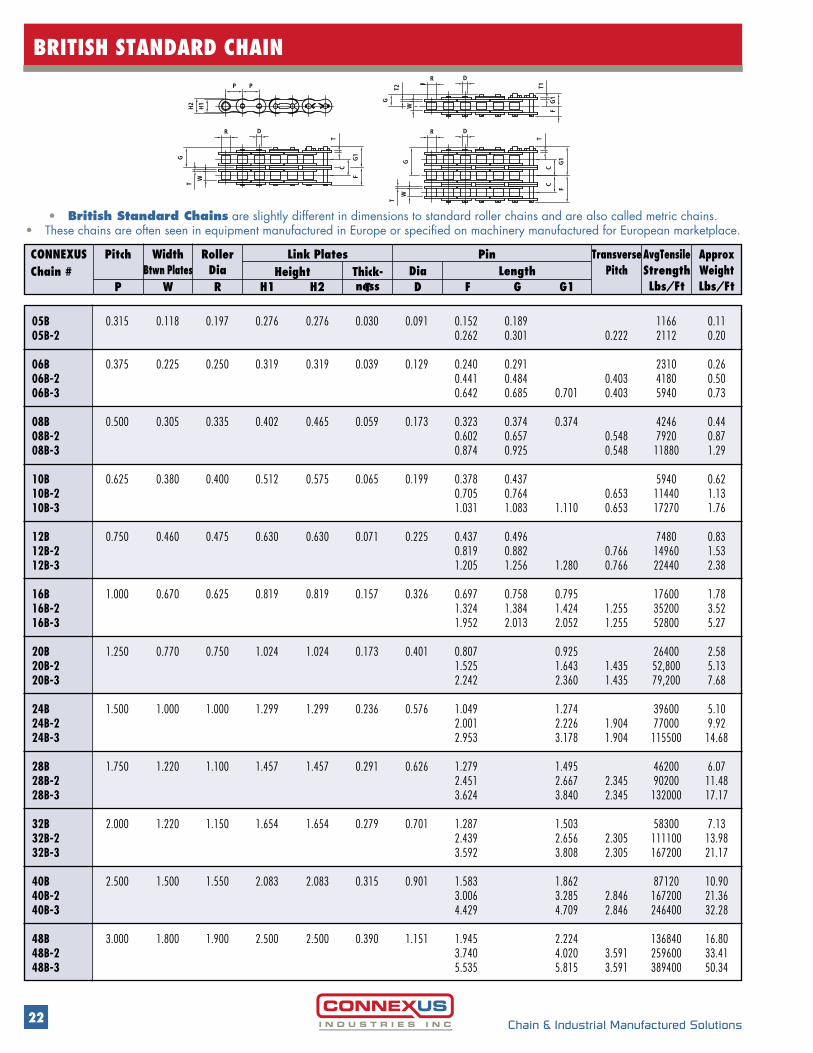
BRITISH STANDARD CHAIN
T2
W
T
W
DR
T
WH
2
H1
T
F
C
CC
FF
DR
R D
TT1P P
G
G G1
G1
G1
G
• British Standard Chains are slightly different in dimensions to standard roller chains and are also called metric chains. • These chains are often seen in equipment manufactured in Europe or specified on machinery manufactured for European marketplace.
CONNEXUS Chain #
WidthBtwn Plates
RollerDia
TransversePitch
AvgTensileStrengthLbs/Ft
ApproxWeightLbs/Ft
Dia LengthHeightLink Plates PinPitch
Thick-nessP W R H1 H2 T D F G G1
05B 0.315 0.118 0.197 0.276 0.276 0.030 0.091 0.152 0.189 1166 0.1105B-2 0.262 0.301 0.222 2112 0.20 06B 0.375 0.225 0.250 0.319 0.319 0.039 0.129 0.240 0.291 2310 0.2606B-2 0.441 0.484 0.403 4180 0.5006B-3 0.642 0.685 0.701 0.403 5940 0.73 08B 0.500 0.305 0.335 0.402 0.465 0.059 0.173 0.323 0.374 0.374 4246 0.4408B-2 0.602 0.657 0.548 7920 0.8708B-3 0.874 0.925 0.548 11880 1.29 10B 0.625 0.380 0.400 0.512 0.575 0.065 0.199 0.378 0.437 5940 0.6210B-2 0.705 0.764 0.653 11440 1.1310B-3 1.031 1.083 1.110 0.653 17270 1.76 12B 0.750 0.460 0.475 0.630 0.630 0.071 0.225 0.437 0.496 7480 0.8312B-2 0.819 0.882 0.766 14960 1.5312B-3 1.205 1.256 1.280 0.766 22440 2.38 16B 1.000 0.670 0.625 0.819 0.819 0.157 0.326 0.697 0.758 0.795 17600 1.7816B-2 1.324 1.384 1.424 1.255 35200 3.5216B-3 1.952 2.013 2.052 1.255 52800 5.27 20B 1.250 0.770 0.750 1.024 1.024 0.173 0.401 0.807 0.925 26400 2.5820B-2 1.525 1.643 1.435 52,800 5.1320B-3 2.242 2.360 1.435 79,200 7.68 24B 1.500 1.000 1.000 1.299 1.299 0.236 0.576 1.049 1.274 39600 5.1024B-2 2.001 2.226 1.904 77000 9.9224B-3 2.953 3.178 1.904 115500 14.68 28B 1.750 1.220 1.100 1.457 1.457 0.291 0.626 1.279 1.495 46200 6.0728B-2 2.451 2.667 2.345 90200 11.4828B-3 3.624 3.840 2.345 132000 17.17 32B 2.000 1.220 1.150 1.654 1.654 0.279 0.701 1.287 1.503 58300 7.1332B-2 2.439 2.656 2.305 111100 13.9832B-3 3.592 3.808 2.305 167200 21.17 40B 2.500 1.500 1.550 2.083 2.083 0.315 0.901 1.583 1.862 87120 10.9040B-2 3.006 3.285 2.846 167200 21.3640B-3 4.429 4.709 2.846 246400 32.28 48B 3.000 1.800 1.900 2.500 2.500 0.390 1.151 1.945 2.224 136840 16.8048B-2 3.740 4.020 3.591 259600 33.4148B-3 5.535 5.815 3.591 389400 50.34
23Chain & Industrial Manufactured Solutions
LEAF CHAIN GENERAL INFO
GENERAL PRECAUTIONS
• Use factory supplied lengths - do not assemble chains from individual components
• Do not replace individual worn parts
• No leaf chain should be plated or painted
• No welding is allowed on any leaf chain or weld splatter allowed to come into contact with chains
• Leaf chains are used on sheaves not sprockets. These sheaves should be inspected on a regular basis for worn flanges
• In order to provide good service life, lubrication must be provided on a regular basis
• Whatever lubrication, SAE 30 is standard. The lubrication must penetrate the chain and reach the joints
• ANSI recommendation on lubrication, checking for wear, and installation guides are available from our service centers
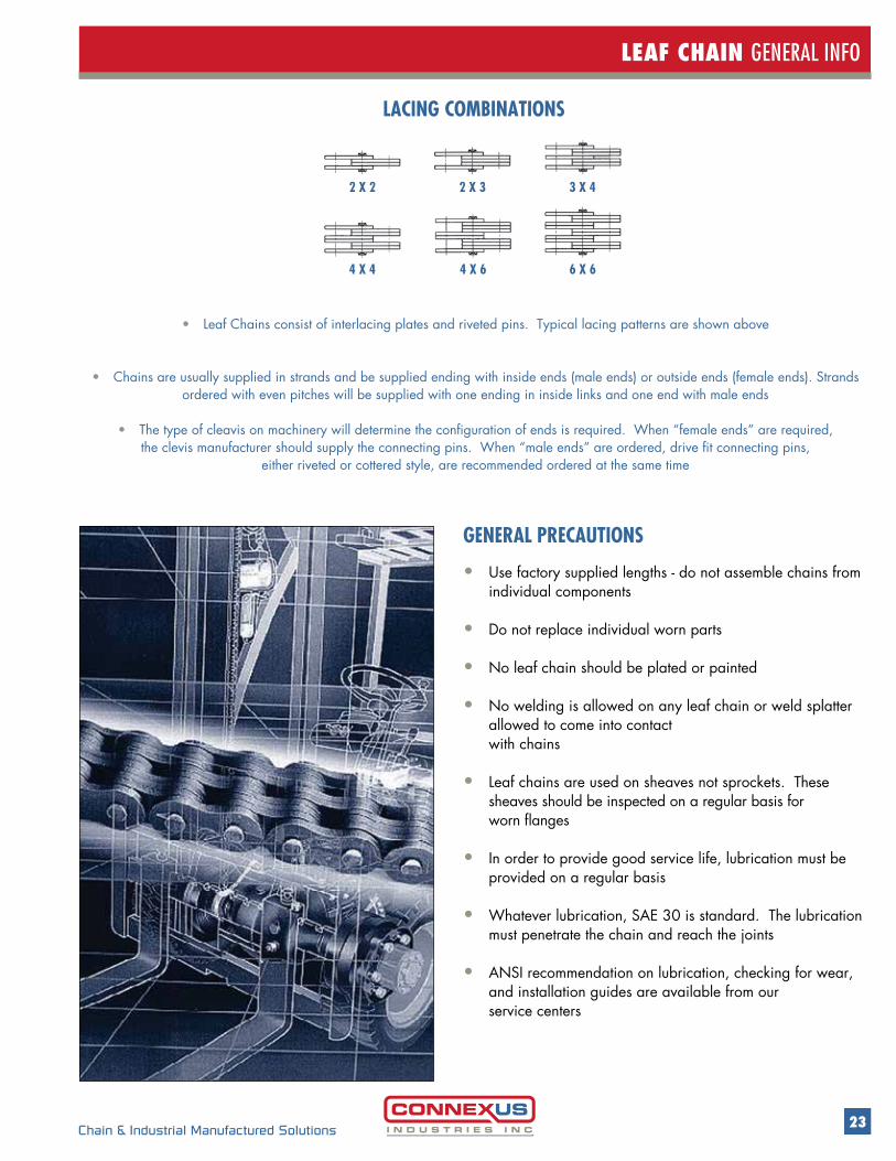
2 X 2
4 X 4 4 X 6 6 X 6
2 X 3 3 X 4
LACING COMBINATIONS
• Leaf Chains consist of interlacing plates and riveted pins. Typical lacing patterns are shown above
• Chains are usually supplied in strands and be supplied ending with inside ends (male ends) or outside ends (female ends). Strands ordered with even pitches will be supplied with one ending in inside links and one end with male ends
• The type of cleavis on machinery will determine the configuration of ends is required. When “female ends” are required, the clevis manufacturer should supply the connecting pins. When “male ends” are ordered, drive fit connecting pins,
either riveted or cottered style, are recommended ordered at the same time
24 Chain & Industrial Manufactured Solutions
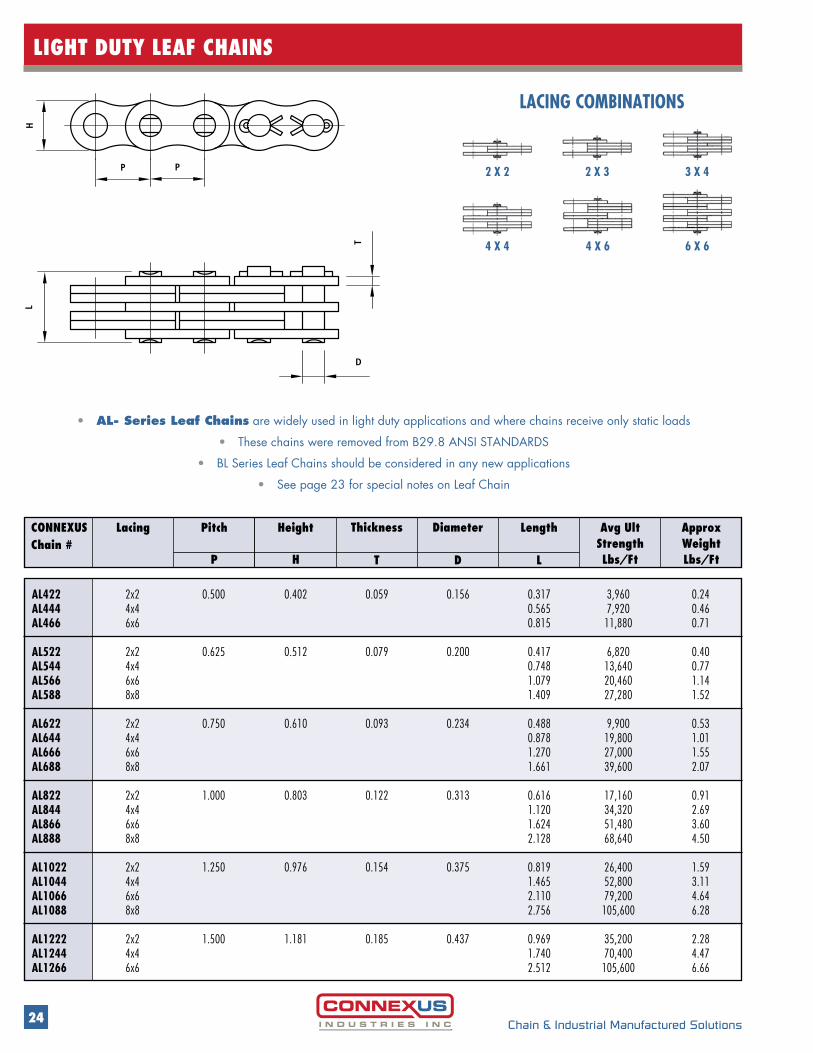
LIGHT DUTY LEAF CHAINS
CONNEXUS Chain #
Pitch Approx WeightLbs/Ft
Avg UltStrengthLbs/Ft
Height LengthLacing Thickness Diameter
P H DT L
AL422 2x2 0.500 0.402 0.059 0.156 0.317 3,960 0.24AL444 4x4 0.565 7,920 0.46AL466 6x6 0.815 11,880 0.71 AL522 2x2 0.625 0.512 0.079 0.200 0.417 6,820 0.40AL544 4x4 0.748 13,640 0.77AL566 6x6 1.079 20,460 1.14AL588 8x8 1.409 27,280 1.52 AL622 2x2 0.750 0.610 0.093 0.234 0.488 9,900 0.53AL644 4x4 0.878 19,800 1.01AL666 6x6 1.270 27,000 1.55AL688 8x8 1.661 39,600 2.07 AL822 2x2 1.000 0.803 0.122 0.313 0.616 17,160 0.91AL844 4x4 1.120 34,320 2.69AL866 6x6 1.624 51,480 3.60AL888 8x8 2.128 68,640 4.50 AL1022 2x2 1.250 0.976 0.154 0.375 0.819 26,400 1.59AL1044 4x4 1.465 52,800 3.11AL1066 6x6 2.110 79,200 4.64AL1088 8x8 2.756 105,600 6.28 AL1222 2x2 1.500 1.181 0.185 0.437 0.969 35,200 2.28AL1244 4x4 1.740 70,400 4.47AL1266 6x6 2.512 105,600 6.66
• AL- Series Leaf Chains are widely used in light duty applications and where chains receive only static loads
• These chains were removed from B29.8 ANSI STANDARDS
• BL Series Leaf Chains should be considered in any new applications
• See page 23 for special notes on Leaf Chain
2 X 2
4 X 4 4 X 6 6 X 6
2 X 3 3 X 4
LACING COMBINATIONS
H
PP
L
DT
25Chain & Industrial Manufactured Solutions
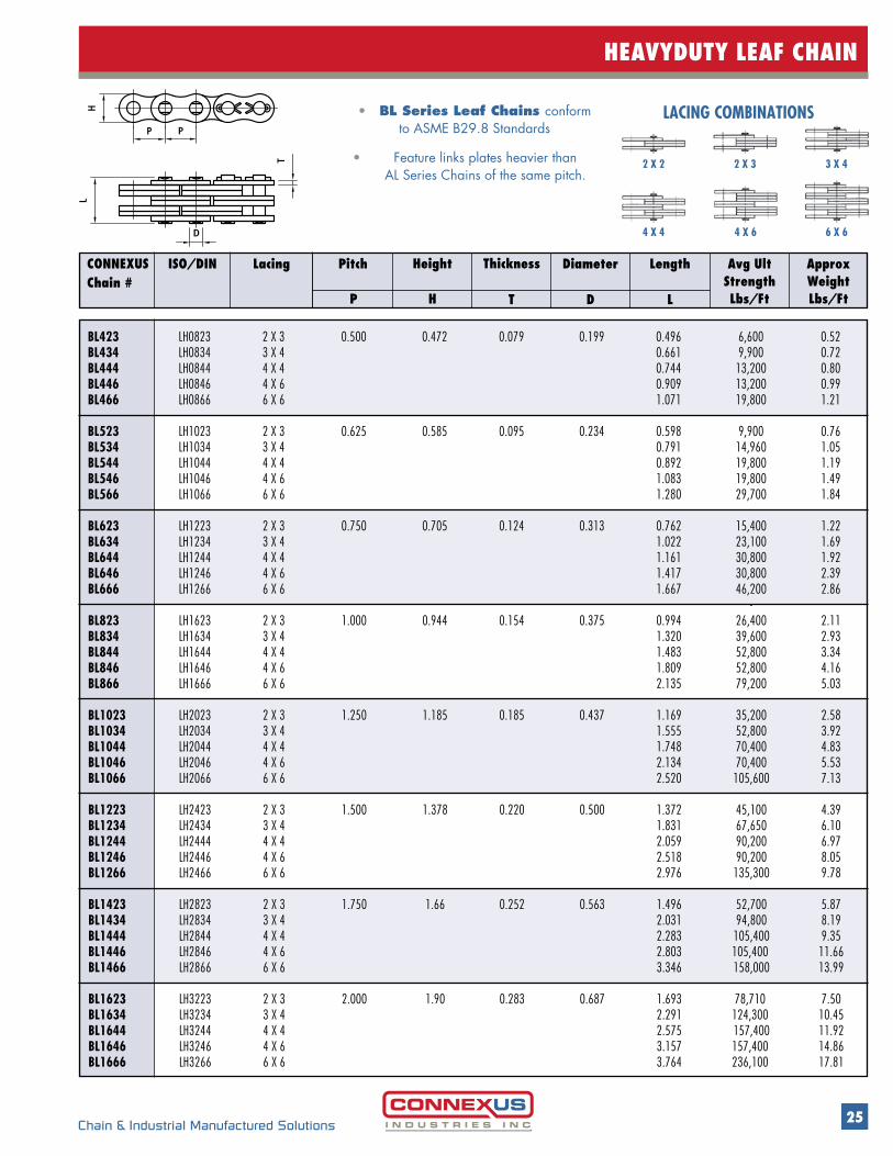
HEAVYDUTY LEAF CHAIN
CONNEXUS Chain #
Lacing Approx WeightLbs/Ft
Avg UltStrengthLbs/Ft
Pitch Diameter LengthISO/DIN Height Thickness
HP T D L
BL423 LH0823 2 X 3 0.500 0.472 0.079 0.199 0.496 6,600 0.52BL434 LH0834 3 X 4 0.661 9,900 0.72BL444 LH0844 4 X 4 0.744 13,200 0.80BL446 LH0846 4 X 6 0.909 13,200 0.99BL466 LH0866 6 X 6 1.071 19,800 1.21
BL523 LH1023 2 X 3 0.625 0.585 0.095 0.234 0.598 9,900 0.76BL534 LH1034 3 X 4 0.791 14,960 1.05BL544 LH1044 4 X 4 0.892 19,800 1.19BL546 LH1046 4 X 6 1.083 19,800 1.49BL566 LH1066 6 X 6 1.280 29,700 1.84 BL623 LH1223 2 X 3 0.750 0.705 0.124 0.313 0.762 15,400 1.22BL634 LH1234 3 X 4 1.022 23,100 1.69BL644 LH1244 4 X 4 1.161 30,800 1.92BL646 LH1246 4 X 6 1.417 30,800 2.39BL666 LH1266 6 X 6 1.667 46,200 2.86 - BL823 LH1623 2 X 3 1.000 0.944 0.154 0.375 0.994 26,400 2.11BL834 LH1634 3 X 4 1.320 39,600 2.93BL844 LH1644 4 X 4 1.483 52,800 3.34BL846 LH1646 4 X 6 1.809 52,800 4.16BL866 LH1666 6 X 6 2.135 79,200 5.03
BL1023 LH2023 2 X 3 1.250 1.185 0.185 0.437 1.169 35,200 2.58BL1034 LH2034 3 X 4 1.555 52,800 3.92BL1044 LH2044 4 X 4 1.748 70,400 4.83BL1046 LH2046 4 X 6 2.134 70,400 5.53BL1066 LH2066 6 X 6 2.520 105,600 7.13 BL1223 LH2423 2 X 3 1.500 1.378 0.220 0.500 1.372 45,100 4.39BL1234 LH2434 3 X 4 1.831 67,650 6.10BL1244 LH2444 4 X 4 2.059 90,200 6.97BL1246 LH2446 4 X 6 2.518 90,200 8.05BL1266 LH2466 6 X 6 2.976 135,300 9.78 BL1423 LH2823 2 X 3 1.750 1.66 0.252 0.563 1.496 52,700 5.87BL1434 LH2834 3 X 4 2.031 94,800 8.19BL1444 LH2844 4 X 4 2.283 105,400 9.35BL1446 LH2846 4 X 6 2.803 105,400 11.66BL1466 LH2866 6 X 6 3.346 158,000 13.99 BL1623 LH3223 2 X 3 2.000 1.90 0.283 0.687 1.693 78,710 7.50BL1634 LH3234 3 X 4 2.291 124,300 10.45BL1644 LH3244 4 X 4 2.575 157,400 11.92BL1646 LH3246 4 X 6 3.157 157,400 14.86BL1666 LH3266 6 X 6 3.764 236,100 17.81
• BL Series Leaf Chains conform to ASME B29.8 Standards
• Feature links plates heavier than AL Series Chains of the same pitch.
2 X 2
4 X 4 4 X 6 6 X 6
2 X 3 3 X 4
LACING COMBINATIONS
L
D
H
PP
T
26 Chain & Industrial Manufactured Solutions
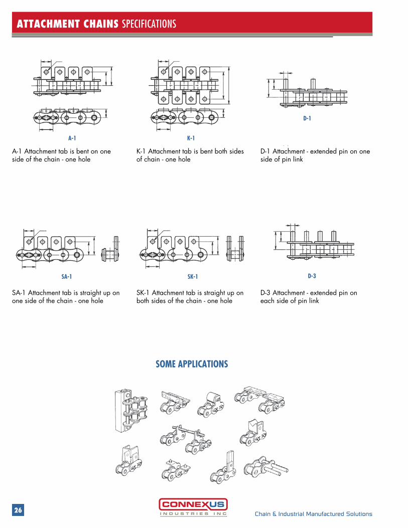
ATTACHMENT CHAINS SPECIFICATIONS
A-1 K-1
D-1
A-1 Attachment tab is bent on one side of the chain - one hole
K-1 Attachment tab is bent both sides of chain - one hole
D-1 Attachment - extended pin on one side of pin link
SA-1 SK-1 D-3
SA-1 Attachment tab is straight up on one side of the chain - one hole
SK-1 Attachment tab is straight up on both sides of the chain - one hole
D-3 Attachment - extended pin on each side of pin link
SOME APPLICATIONS
27Chain & Industrial Manufactured Solutions
ATTACHMENT CHAINS SPECIFICATIONS
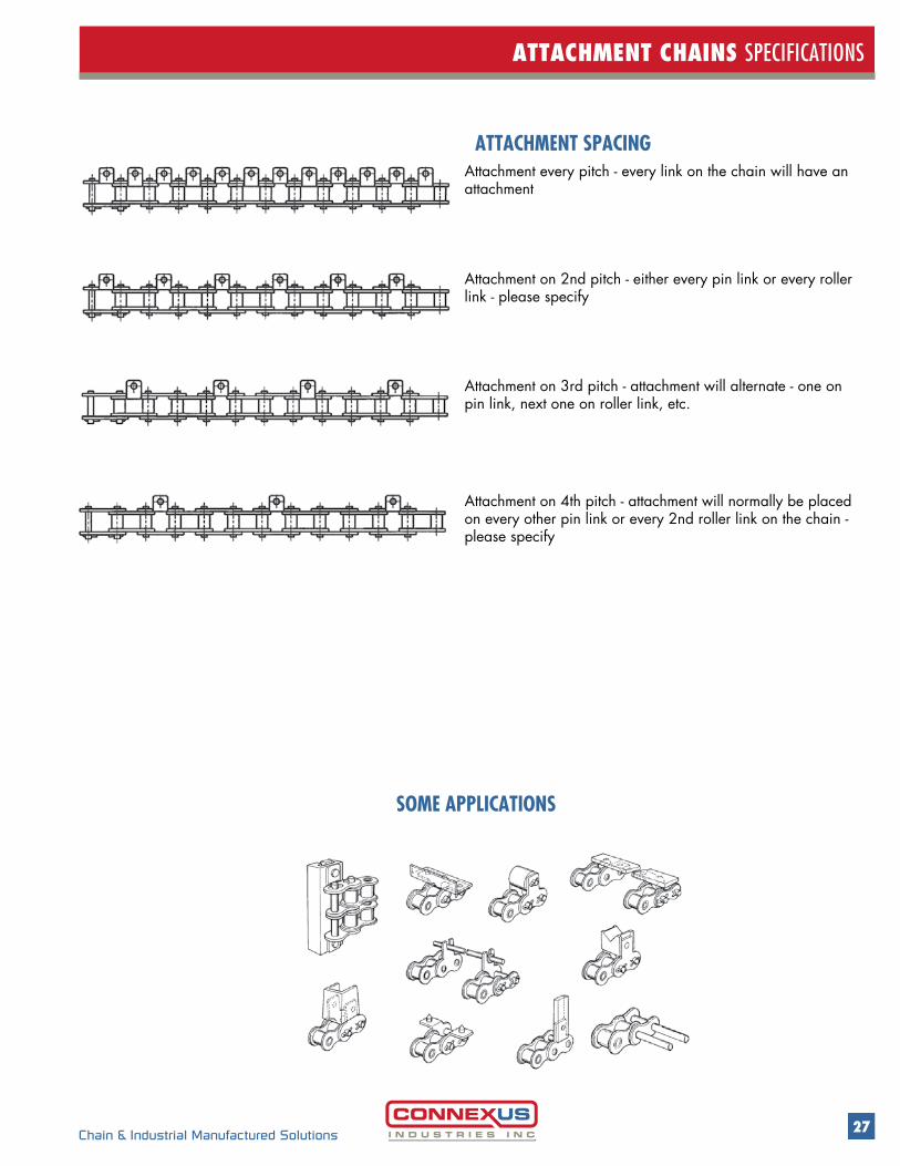
ATTACHMENT SPACING
SOME APPLICATIONS
Attachment every pitch - every link on the chain will have an attachment
Attachment on 2nd pitch - either every pin link or every roller link - please specify
Attachment on 3rd pitch - attachment will alternate - one on pin link, next one on roller link, etc.
Attachment on 4th pitch - attachment will normally be placed on every other pin link or every 2nd roller link on the chain - please specify
28 Chain & Industrial Manufactured Solutions
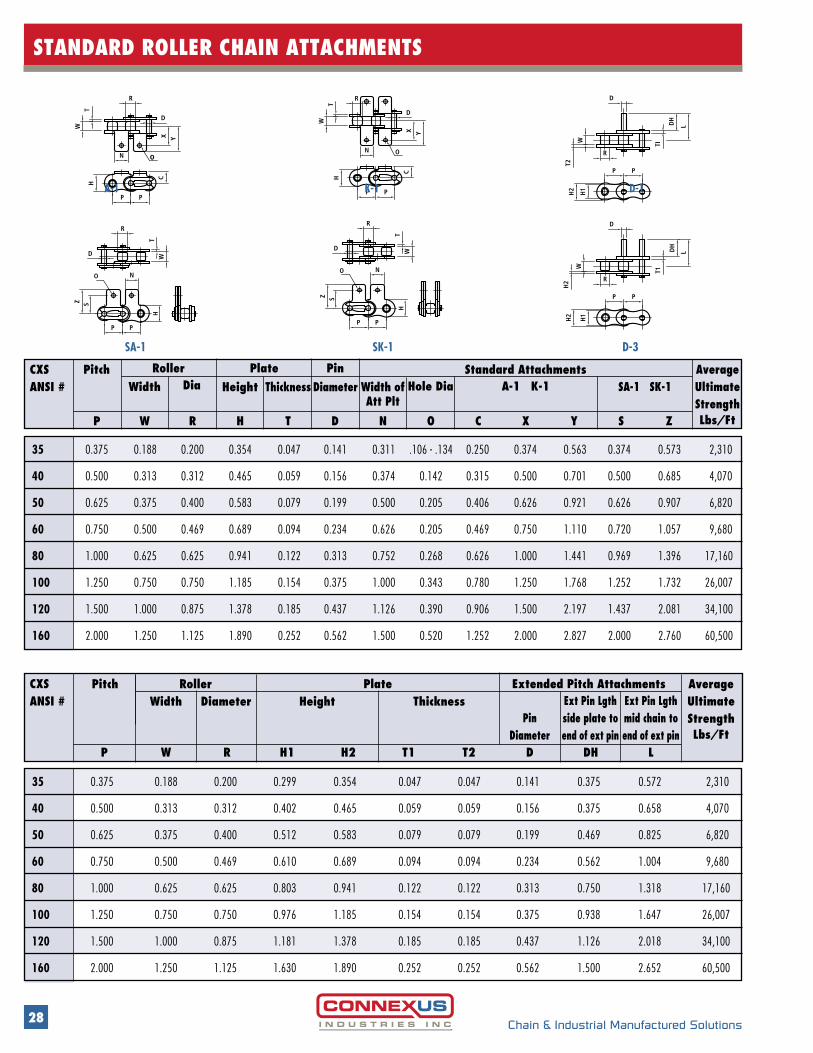
STANDARD ROLLER CHAIN ATTACHMENTS
CXS ANSI # Width
Roller Plate PinDia SA-1 SK-1
Average UltimateStrengthLbs/Ft
Hole Dia A-1 K-1Height Thickness DiameterStandard AttachmentsPitch
Width ofAtt Plt
P W R H T D N O C X Y S Z
35 0.375 0.188 0.200 0.354 0.047 0.141 0.311 .106 - .134 0.250 0.374 0.563 0.374 0.573 2,310
40 0.500 0.313 0.312 0.465 0.059 0.156 0.374 0.142 0.315 0.500 0.701 0.500 0.685 4,070
50 0.625 0.375 0.400 0.583 0.079 0.199 0.500 0.205 0.406 0.626 0.921 0.626 0.907 6,820
60 0.750 0.500 0.469 0.689 0.094 0.234 0.626 0.205 0.469 0.750 1.110 0.720 1.057 9,680
80 1.000 0.625 0.625 0.941 0.122 0.313 0.752 0.268 0.626 1.000 1.441 0.969 1.396 17,160
100 1.250 0.750 0.750 1.185 0.154 0.375 1.000 0.343 0.780 1.250 1.768 1.252 1.732 26,007
120 1.500 1.000 0.875 1.378 0.185 0.437 1.126 0.390 0.906 1.500 2.197 1.437 2.081 34,100
160 2.000 1.250 1.125 1.890 0.252 0.562 1.500 0.520 1.252 2.000 2.827 2.000 2.760 60,500
35 0.375 0.188 0.200 0.299 0.354 0.047 0.047 0.141 0.375 0.572 2,310
40 0.500 0.313 0.312 0.402 0.465 0.059 0.059 0.156 0.375 0.658 4,070
50 0.625 0.375 0.400 0.512 0.583 0.079 0.079 0.199 0.469 0.825 6,820
60 0.750 0.500 0.469 0.610 0.689 0.094 0.094 0.234 0.562 1.004 9,680
80 1.000 0.625 0.625 0.803 0.941 0.122 0.122 0.313 0.750 1.318 17,160
100 1.250 0.750 0.750 0.976 1.185 0.154 0.154 0.375 0.938 1.647 26,007
120 1.500 1.000 0.875 1.181 1.378 0.185 0.185 0.437 1.126 2.018 34,100
160 2.000 1.250 1.125 1.630 1.890 0.252 0.252 0.562 1.500 2.652 60,500
CXS ANSI #
RollerPitchExt Pin Lgthmid chain toend of ext pin
Ext Pin Lgthside plate toend of ext pin
PinDiameter
Average UltimateStrengthLbs/Ft
HeightDiameterWidth ThicknessPlate Extended Pitch Attachments
LDHDT2T1H2H1RWP
Y
P
N
H
CO
P
N
P
W
WT
HT
D
R
Z S
O
P
D
R
Y
P
H
P
N
C
O
WP
R
TW
HP
N
Z S
O
T
R
D
X
D
X
A-1
SA-1
Y
P
N
H
C
O
P
N
P
W
WT
HT
D
R
Z S
O
P
D
R
Y
P
H
P
N
C
O
W
P
R
TW
H
P
N
Z S
O
T
R
D
X
D
X
K-1
R
H2
H1
T2
W
PP
LDH
D
TI
R
P
H2
H1
P
D
W
H2
L
T1
DH
D-1
SK-1 D-3
29Chain & Industrial Manufactured Solutions
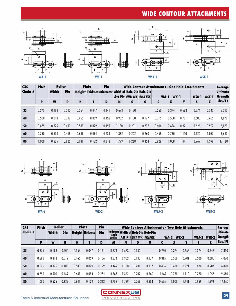
WIDE CONTOUR ATTACHMENTS
35 0.375 0.188 0.200 0.354 0.047 0.141 0.374 0.673 0.130 0.250 0.374 0.563 0.374 0.543 2,310
40 0.500 0.313 0.312 0.465 0.059 0.156 0.374 0.902 0.130 0.177 0.315 0.500 0.701 0.500 0.685 4,070
50 0.625 0.375 0.400 0.583 0.079 0.199 0.469 1.130 0.201 0.217 0.406 0.626 0.921 0.626 0.907 6,820
60 0.750 0.500 0.469 0.689 0.094 0.234 0.563 1.362 0.202 0.260 0.469 0.750 1.110 0.720 1.057 9,680
80 1.000 0.625 0.625 0.941 0.122 0.313 0.752 1.799 0.268 0.354 0.626 1.000 1.441 0.969 1.396 17,160
CXS Chain # Width
Roller Plate Pin
Dia DiaWSA-2 WSK-2
AverageUltimateStrengthLbs/Ft
HoleDia(WA WK)
HoleDia(WSA WSK) WA-2 WK-2
Height Thickness Dist betweenholes inAtt Plate
Wide Contour Attachments - Two Hole AttachmentsPitchWidth ofAtt Plt
P W R H T D M N O O XC Y S Z
N
P
H
P
C
N
P
W W
T
HT
D
R
T
P
D
R
T
Y
P
H
P
C
W
N
P
W
T
H
P
T
D
Z
T
R
T
D
S S
MO
MO
X
MO
X
O
Z
Y R
M
N
WA-2 WK-2 WSA-2 WSK-2
35 0.375 0.188 0.200 0.354 0.047 0.141 0.673 0.130 0.250 0.374 0.563 0.374 0.543 2,310
40 0.500 0.313 0.312 0.465 0.059 0.156 0.902 0.130 0.177 0.315 0.500 0.701 0.500 0.685 4,070
50 0.625 0.375 0.400 0.583 0.079 0.199 1.130 0.201 0.217 0.406 0.626 0.921 0.626 0.907 6,820
60 0.750 0.500 0.469 0.689 0.094 0.234 1.362 0.202 0.260 0.469 0.750 1.110 0.720 1.057 9,680
80 1.000 0.625 0.625 0.941 0.122 0.313 1.799 0.268 0.354 0.626 1.000 1.441 0.969 1.396 17,160
W
N
P
H
P
C
ON
P
W
T
HT
D
R
T
P
O
D
R
T
W
N
P
H
P
O
C
T
N
P
T
H
P
T
O
T
R
T
D
R
SZ
X Y
X Y
Z S
D
WA-1 WK-1 WSA-1 WSK-1
CXS Chain # Width
Roller Plate PinDia
WSA-1 WSK-1
AverageUltimateStrengthLbs/Ft
Hole Dia (WA WK)
Hole Dia(WSA WSK) WA-1 WK-1
Height Thickness DiameterWide Contour Attachments - One Hole AttachmentsPitch
Width ofAtt Plt
P W R H T D N O O XC Y S Z

30 Chain & Industrial Manufactured Solutions
SS MEGA ATTACHMENT CHAIN SPECIFICATIONS
• Roller chain sizes 40 through 80, single and double
• Double pitch chain C2040 through C2080
• All standard attachments
• Patented design pro-vides twice the tensile strength of standard stainless steel chains
• Patented design provides;
• twice the tensile strength of
standard stainless steel chains
• twice the allowable load • 50% better
elongation results • pin protection from debris
• Uses standard sprockets
• Reduces maintenance
MEGA CHAIN DETAIL
MEGA ATTACHMENT
MEGA CHAIN
Inner Plate Dust Prevention Outer Plate

31Chain & Industrial Manufactured Solutions
SS MEGA ATTACHMENT CHAIN SPECIFICATIONS
CXSMega Chain #
WidthRoller Plate Pin
DiaSA-1 SK-1
AverageUltimateStrengthLbs/Ft
Max Allow Load
Lbs/Ft
HoleDia A-1 K-1
Height Thickness DiameterStandard AttachmentsPitch
Width ofAtt Plt
P W R H T D N O C YX S Z
40SS 0.500 0.313 0.312 0.472 0.059 0.156 0.374 0.142 0.315 0.500 0.701 0.500 0.685 154 3,960
50SS 0.625 0.375 0.400 0.591 0.079 0.199 0.500 0.205 0.406 0.626 0.921 0.626 0.907 264 7,040
60SS 0.750 0.500 0.469 0.713 0.093 0.234 0.625 0.205 0.469 0.750 1.110 0.720 1.057 363 9,680
80SS 1.000 0.625 0.625 0.945 0.118 0.313 0.752 0.268 0.626 1.000 1.441 0.969 1.396 638 15,840
4
ME
W
H
SS0
GA
S04
S
AE
M
G
S04
S
M
E GA
S4S0
M
GE A
C
S
P
4
MH
S0 S
GE A
SS4
0
GE
M
A
S04
S
E
M
AG
40 S
M
E AG
CY
W
T
R
N O
D
X
ON
W
T
R
Y
D
X
A-1
K-1
32 Chain & Industrial Manufactured Solutions
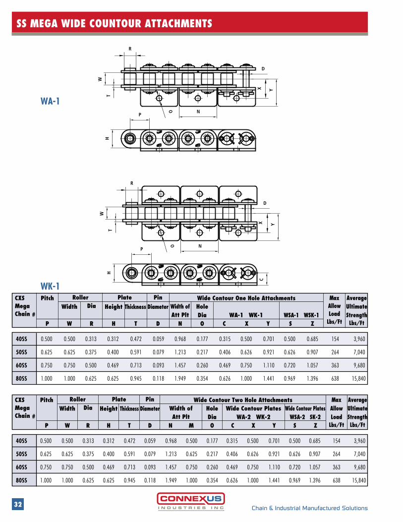
SS MEGA WIDE COUNTOUR ATTACHMENTS
CXSMega Chain #
WidthRoller Plate Pin
DiaWSA-1 WSK-1
AverageUltimateStrengthLbs/Ft
Max Allow Load
Lbs/Ft
HoleDia WA-1 WK-1
Height Thickness DiameterWide Contour One Hole AttachmentsPitch
Width ofAtt Plt
P W R H T D N O C YX S Z
40SS 0.500 0.500 0.313 0.312 0.472 0.059 0.968 0.177 0.315 0.500 0.701 0.500 0.685 154 3,960
50SS 0.625 0.625 0.375 0.400 0.591 0.079 1.213 0.217 0.406 0.626 0.921 0.626 0.907 264 7,040
60SS 0.750 0.750 0.500 0.469 0.713 0.093 1.457 0.260 0.469 0.750 1.110 0.720 1.057 363 9,680
80SS 1.000 1.000 0.625 0.625 0.945 0.118 1.949 0.354 0.626 1.000 1.441 0.969 1.396 638 15,840
CXSMega Chain #
WidthRoller Plate Pin
Dia Wide Contour PlatesWSA-2 SK-2
AverageUltimateStrengthLbs/Ft
Max Allow Load
Lbs/Ft
HoleDia
Wide Contour PlatesWA-2 WK-2
Height Thickness DiameterWide Contour Two Hole AttachmentsPitch
Width ofAtt Plt
P W R H T D N M O C YX S Z
40SS 0.500 0.500 0.313 0.312 0.472 0.059 0.968 0.500 0.177 0.315 0.500 0.701 0.500 0.685 154 3,960
50SS 0.625 0.625 0.375 0.400 0.591 0.079 1.213 0.625 0.217 0.406 0.626 0.921 0.626 0.907 264 7,040
60SS 0.750 0.750 0.500 0.469 0.713 0.093 1.457 0.750 0.260 0.469 0.750 1.110 0.720 1.057 363 9,680
80SS 1.000 1.000 0.625 0.625 0.945 0.118 1.949 1.000 0.354 0.626 1.000 1.441 0.969 1.396 638 15,840
4
M
E
P
H
SS0
GA
S04
S
AE
M
G
S04
S
M
E GA
S4S0
M
GE A
A
P
H
S04
S
AE
M
G
S40 S
M
E AG
S4S0
M
GE A
04
S
E
M
G
S
W
T
R
NO
D
X Y
NO
R
T
W
C
YX
D
WA-1
WK-1
33Chain & Industrial Manufactured Solutions
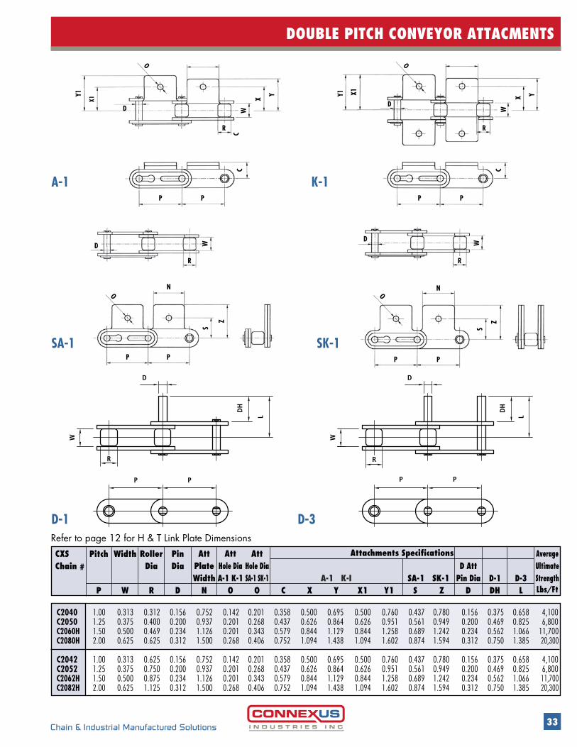
DOUBLE PITCH CONVEYOR ATTACMENTS
C2040 1.00 0.313 0.312 0.156 0.752 0.142 0.201 0.358 0.500 0.695 0.500 0.760 0.437 0.780 0.156 0.375 0.658 4,100 C2050 1.25 0.375 0.400 0.200 0.937 0.201 0.268 0.437 0.626 0.864 0.626 0.951 0.561 0.949 0.200 0.469 0.825 6,800 C2060H 1.50 0.500 0.469 0.234 1.126 0.201 0.343 0.579 0.844 1.129 0.844 1.258 0.689 1.242 0.234 0.562 1.066 11,700 C2080H 2.00 0.625 0.625 0.312 1.500 0.268 0.406 0.752 1.094 1.438 1.094 1.602 0.874 1.594 0.312 0.750 1.385 20,300 C2042 1.00 0.313 0.625 0.156 0.752 0.142 0.201 0.358 0.500 0.695 0.500 0.760 0.437 0.780 0.156 0.375 0.658 4,100 C2052 1.25 0.375 0.750 0.200 0.937 0.201 0.268 0.437 0.626 0.864 0.626 0.951 0.561 0.949 0.200 0.469 0.825 6,800 C2062H 1.50 0.500 0.875 0.234 1.126 0.201 0.343 0.579 0.844 1.129 0.844 1.258 0.689 1.242 0.234 0.562 1.066 11,700 C2082H 2.00 0.625 1.125 0.312 1.500 0.268 0.406 0.752 1.094 1.438 1.094 1.602 0.874 1.594 0.312 0.750 1.385 20,300
CXS Chain #
Width RollerDia
PinDia
D-3D-1
AverageUltimateStrengthLbs/Ft
A-1 K-I SA-1 SK-1
AttPlateWidth
AttHole DiaA-1 K-1
Att Hole DiaSA-1 SK-1
D Att
Pin Dia
Attachments SpecificationsPitch
P W R D N O O C X Y X1 SY1 Z DHD L
A-1 K-1
R
O
N
PP
S
Z
D W
O
P P
N
R
D
S
Z
W
O O
R
P P
R
D D
Y1
X1
P P
CC
Y1 X1
CW
X
Y
W
X Y
D
P
R
W
DH
P
L L
P
D
P
R
W
DH
D-1 D-3Refer to page 12 for H & T Link Plate Dimensions
SA-1 SK-1
34 Chain & Industrial Manufactured Solutions
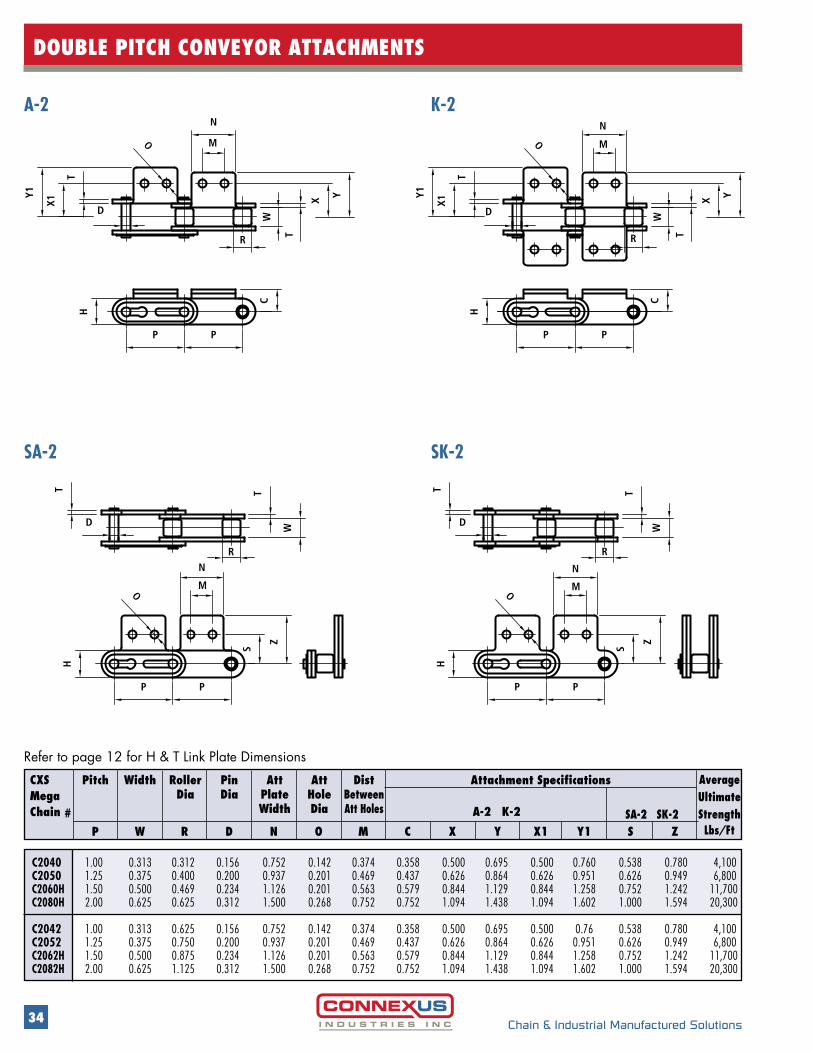
DOUBLE PITCH CONVEYOR ATTACHMENTS
C2040 1.00 0.313 0.312 0.156 0.752 0.142 0.374 0.358 0.500 0.695 0.500 0.760 0.538 0.780 4,100C2050 1.25 0.375 0.400 0.200 0.937 0.201 0.469 0.437 0.626 0.864 0.626 0.951 0.626 0.949 6,800C2060H 1.50 0.500 0.469 0.234 1.126 0.201 0.563 0.579 0.844 1.129 0.844 1.258 0.752 1.242 11,700C2080H 2.00 0.625 0.625 0.312 1.500 0.268 0.752 0.752 1.094 1.438 1.094 1.602 1.000 1.594 20,300 C2042 1.00 0.313 0.625 0.156 0.752 0.142 0.374 0.358 0.500 0.695 0.500 0.76 0.538 0.780 4,100C2052 1.25 0.375 0.750 0.200 0.937 0.201 0.469 0.437 0.626 0.864 0.626 0.951 0.626 0.949 6,800C2062H 1.50 0.500 0.875 0.234 1.126 0.201 0.563 0.579 0.844 1.129 0.844 1.258 0.752 1.242 11,700C2082H 2.00 0.625 1.125 0.312 1.500 0.268 0.752 0.752 1.094 1.438 1.094 1.602 1.000 1.594 20,300
CXSMega Chain # SA-2 SK-2
AverageUltimateStrengthLbs/Ft
A-2 K-2
Attachment SpecificationsPitch Width RollerDia
PinDia
AttPlateWidth
AttHoleDia
DistBetweenAtt Holes
P W R D N O M C X X1 Y1Y S Z
TH
Y1
X1
D
P
H
C
P
R
P
T
O
H
O
D
T
R
YX
T
P
M
N
N
S
M
T
P
H
P
R
M
N
PP
O
O
T
W
W W
Z Z
S
D
YX
T
W
R
Y1
D
X1
T
N
M
C
A-2 K-2
TH
Y1
X1
D
P
H
C
P
R
P
T
O
H
O
D
T
R
YX
T
P
M
N
N
S
M
T
P
H
P
R
M
N
PP
O
O
T
W
W W
Z Z
S
D
YX
T
W
R
Y1
D
X1
T
N
M
C
SA-2 SK-2
Refer to page 12 for H & T Link Plate Dimensions

35
DOUBLE PLUS CHAINS
Chain & Industrial Manufactured Solutions
.575
.750
1.20
5
.497
1.23
6
1.54
3
1.25
.080
.200
TW
PP
R
R1
W1
H
D
GF
.575
.750
1.20
5
.497
1.23
6
1.54
3
1.25
.080
.200
TRIPLE SPEED CHAINS
• Conveyor Chains with a black plastic (POM 90) large roller which inhibits static electricity, and small gray (nylon 66 ) material roller allows for material to be transported at 2.5 times the speed of the base chain
• Base chain available in carbon steel, coated with zinc plated inside plates and nickel plated outer plates, as well as stainless steel
Contact CONNEXUS service centers for
special requirements
CONNEXUS Chain #
Width Approx WeightLbs/Ft
Avg UltStrengthLbs/Ft
Height Thickness Diameter LengthsDiameterHeightRoller Plate PinPitch
P W W1 R R1 H T D F G
C2050-JDS 1.25 1.08 0.496 1.205 0.750 0.575 0.080 0.200 0.756 0.815 6600 0.94
C2060H-JDS 1.50 1.31 0.610 1.437 0.886 0.673 0.122 0.234 0.951 1.018 9240 1.34
t Snap covers drawn below, also available from the factory
C2050 - JDS - CVR
36
SPECIAL MARKET CHAINS
Chain & Industrial Manufactured Solutions
DOUBLE FLEX CHAINS
t Transfer conveyor chains used in many applications featuring induction hardened pins, thru hardened sidebars and inner links for extended wear life
CITRUS / AGRICULTURAL CHAINS
• Connexus Citrus, sometimes called agricultural chains, are used to convey product on bucket elevators• They are available with same length of pin and two separate pin diameters, 1/2” and 916”
• Also available in plated and stainless steeConsult Connexus service centers for special requirements
CXS Chain #
Approx WeightLbs/Ft
Avg TensileStrengthLbs/Ft
Dia LengthHeightLink Plates PinType
ThicknessRollerWidth
RollerDia
Pitch
P W R H T D D1 D2 M DH L
C2060H 1/2” 1.500 0.500 0.469 0.670 0.125 0.234 0.310 0.343 0.500 1.625 2.720 1.20 9900 9/16” 0.563
CXS Chain #
Chain WidthPitch Avg UltTensile
StrengthLbs/Ft
MaximumAllowable
LoadLbs
Average Weight
Lbs/Ft
Overall InsideInnerLink
OuterLink
Thickness HeightLink Plate
DiameterPin
RadiusMaximum
RDHTWL
DF3500 3.000” 2.5000” 1.500 0.625 0.250 1.25 0.562 20” 3.3 4000 48000
DH
D2
D1
P
L T
R
HW
P
M
D
MAX. FLEX RADIUSR20.000"
H
W
2.500” 3.000”
L
D
T
A
37
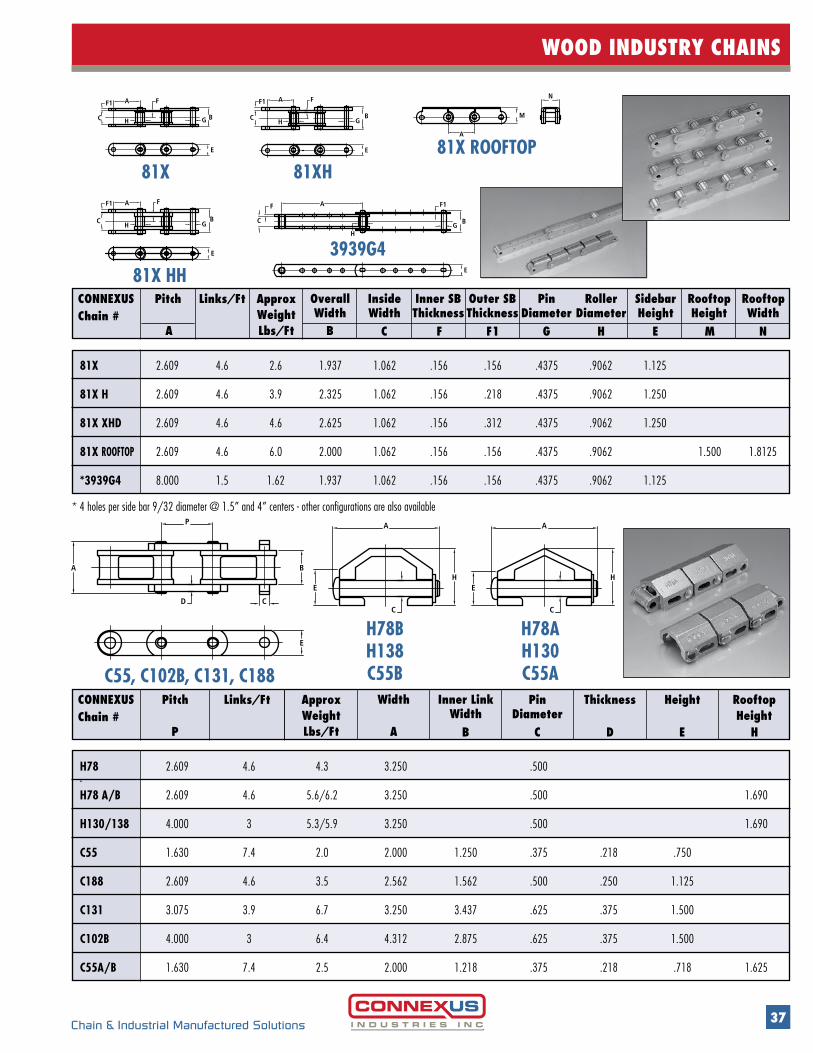
WOOD INDUSTRY CHAINS
Chain & Industrial Manufactured Solutions
A
EH
C
H
A
C
E
CONNEXUSChain #
Links/Ft Approx WeightLbs/Ft
Pitch OverallWidth
InsideWidth
Inner SB Thickness
Outer SB Thickness
PinDiameter
Roller Diameter
RooftopHeight
Rooftop Width
BA C F F1 G H M
SidebarHeight
E N
81X 2.609 4.6 2.6 1.937 1.062 .156 .156 .4375 .9062 1.125
81X H 2.609 4.6 3.9 2.325 1.062 .156 .218 .4375 .9062 1.250
81X XHD 2.609 4.6 4.6 2.625 1.062 .156 .312 .4375 .9062 1.250
81X ROOFTOP 2.609 4.6 6.0 2.000 1.062 .156 .156 .4375 .9062 1.500 1.8125
*3939G4 8.000 1.5 1.62 1.937 1.062 .156 .156 .4375 .9062 1.125
CONNEXUSChain #
Links/Ft Rooftop Height
HeightApprox WeightLbs/Ft
Pin Diameter
ThicknessPitch Width Inner LinkWidth
AP B C D E H
H78 2.609 4.6 4.3 3.250 .500 - H78 A/B 2.609 4.6 5.6/6.2 3.250 .500 1.690
H130/138 4.000 3 5.3/5.9 3.250 .500 1.690
C55 1.630 7.4 2.0 2.000 1.250 .375 .218 .750
C188 2.609 4.6 3.5 2.562 1.562 .500 .250 1.125
C131 3.075 3.9 6.7 3.250 3.437 .625 .375 1.500
C102B 4.000 3 6.4 4.312 2.875 .625 .375 1.500
C55A/B 1.630 7.4 2.5 2.000 1.218 .375 .218 .718 1.625
E
BA
D
P
C
E
BA
D
P
C
C55, C102B, C131, C188
H78BH138C55B
H78AH130C55A
* 4 holes per side bar 9/32 diameter @ 1.5” and 4” centers - other configurations are also available
A
C H G B
AF
C B
HG
A
CH G
B
M
A
N
B
A
CH G
F F
F
EE
F1
F1
E
F1
F1
E
81X
81X HH3939G4
81XH81X ROOFTOP
38 Chain & Industrial Manufactured Solutions
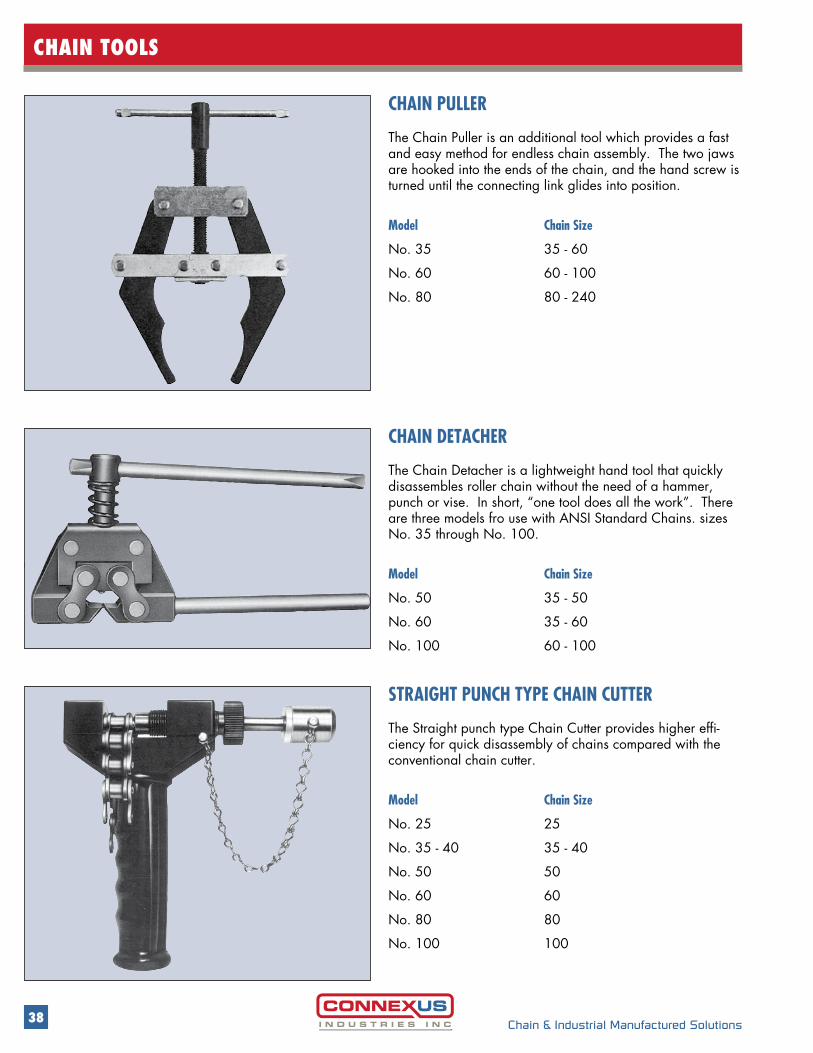
CHAIN TOOLS
CHAIN PULLER
The Chain Puller is an additional tool which provides a fast and easy method for endless chain assembly. The two jaws are hooked into the ends of the chain, and the hand screw is turned until the connecting link glides into position.
Model Chain Size
No. 35 35 - 60
No. 60 60 - 100
No. 80 80 - 240
CHAIN DETACHER
The Chain Detacher is a lightweight hand tool that quickly disassembles roller chain without the need of a hammer, punch or vise. In short, “one tool does all the work”. There are three models fro use with ANSI Standard Chains. sizes No. 35 through No. 100.
Model Chain Size
No. 50 35 - 50
No. 60 35 - 60
No. 100 60 - 100
STRAIGHT PUNCH TYPE CHAIN CUTTER
The Straight punch type Chain Cutter provides higher effi-ciency for quick disassembly of chains compared with the conventional chain cutter.
Model Chain Size
No. 25 25
No. 35 - 40 35 - 40
No. 50 50
No. 60 60
No. 80 80
No. 100 100
39Chain & Industrial Manufactured Solutions
CHAIN DRIVE SELECTION
CHAIN DRIVE SELECTION Chains can be selected by two methods;1. General Selection 2. Slow-speed Selection
1: General Selection The following information is essential in order to select the appropriate chain and sprocket for roller chain transmission
Power to be transmitted = kW Speed of driving shaft and driven shaft per minute Speed ratio refers to the ratio of the speed of the driving shaft to the speed of the driven shaft. The speed ratio of chains can range up to 7:1 under normal operating conditions.
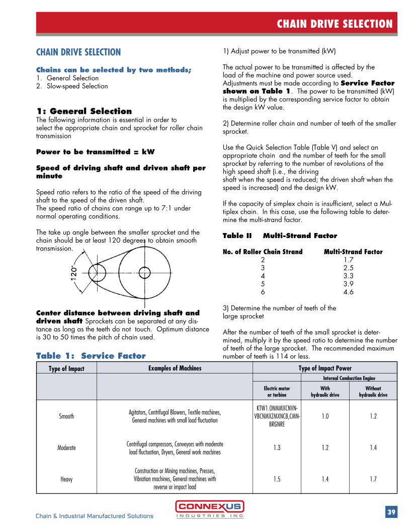
The take up angle between the smaller sprocket and the chain should be at least 120 degrees to obtain smooth transmission.
1) Adjust power to be transmitted (kW)
The actual power to be transmitted is affected by theload of the machine and power source used. Adjustments must be made according to Service Factor shown on Table 1. The power to be transmitted (kW) is multiplied by the corresponding service factor to obtain the design kW value.
2) Determine roller chain and number of teeth of the smaller sprocket. Use the Quick Selection Table (Table V) and select an appropriate chain and the number of teeth for the small sprocket by referring to the number of revolutions of the high speed shaft (i.e., the driving shaft when the speed is reduced; the driven shaft when the speed is increased) and the design kW.
If the capacity of simplex chain is insufficient, select a Mul-tiplex chain. In this case, use the following table to deter-mine the multi-strand factor.
Table II Multi-Strand Factor
No. of Roller Chain Strand Multi-Strand Factor 2 1.7 3 2.5 4 3.3 5 3.9 6 4.6
3) Determine the number of teeth of the large sprocket After the number of teeth of the small sprocket is deter-mined, multiply it by the speed ratio to determine the number of teeth of the large sprocket. The recommended maximum number of teeth is 114 or less.
Center distance between driving shaft and driven shaft Sprockets can be separated at any dis-tance as long as the teeth do not touch. Optimum distance is 30 to 50 times the pitch of chain used.
Construction or Mining machines, Presses, Vibration machines, General machines with
reverse or impact load
Centrifugal compressors, Conveyors with moderate load fluctuation, Dryers, General work machines
Agitators, Centrifugal Blowers, Textile machines, General machines with small load fluctuationSmooth
Type of Impact Examples of Machines Type of Impact PowerInternal Combustion Engine
Electric motor or turbine
With hydraulic drive
Withouthydraulic drive
KTW1.0NMMXCNVN-VBCNMXZMXNCB,CMN-
BRGNRE 1.0 1.2
1.3 1.2 1.4
1.5 1.4 1.7
Moderate
Heavy
Table 1: Service Factor
40
CHAIN DRIVE SELECTION
Chain & Industrial Manufactured Solutions
4) Calculate Chain Length
The number of pitches (length of chain) can be obtained by the following formula (Note: Raise the value to a unit to make it an integer.)
Lp = N1 + N2 + 2 Cp + { (N2 - N1) } / 2 } 2
L: Number of pitches chainN 1: Number of teeth of small sprocketN 2: Number of teeth of large sprocketC: Center distance of two sprockets/Chain Pitch
If the number of pitches is already given, the center distance between the sprockets can be obtained by the following formula:
Cp = 1 { Lp - N1 + N2 + (Lp - N1 + N2) 2 - 2 (N2 -N1)2 } 4 2 ∏2 2
2. Slow Speed SelectionThis is one of the economical selection methods based on fatigue strength of chain for conditions where (i) the operational speed of chain is 50 meters / minute or
less, and (ii) there is no concern of wear elongation and shock
fracture of rollers and bushings. However, a chain selected by this method may be subject to severe conditions and, thus, special care should be taken on the chain selection. The slow speed selection is not applicable to the connecting and offset link.
1) Calculate Chain Tension If the chain tension is unknown, it can be obtained by using the following formula with kW of the input power to be transmitted.
F = 60 x kW (kN) V
F: Chain TensionV: Chain Speed (m/mm)
2) Determine Corrected Chain Tension
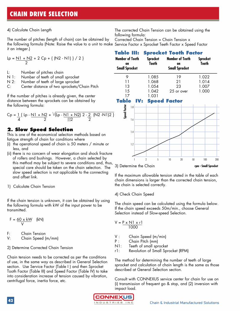
Chain tension needs to be corrected as per the conditions of use, in the same way as described in General Selection section. Use Service Factor (Table I ) and then Sprocket Tooth Factor (Table III) and Speed Factor (Table IV) to take into consideration increase of tension caused by vibration, centrifugal force, inertia force, etc.
The corrected Chain Tension can be obtained using the following formula:Corrected Chain Tension = Chain Tension x Service Factor x Sprocket Teeth Factor x Speed Factor
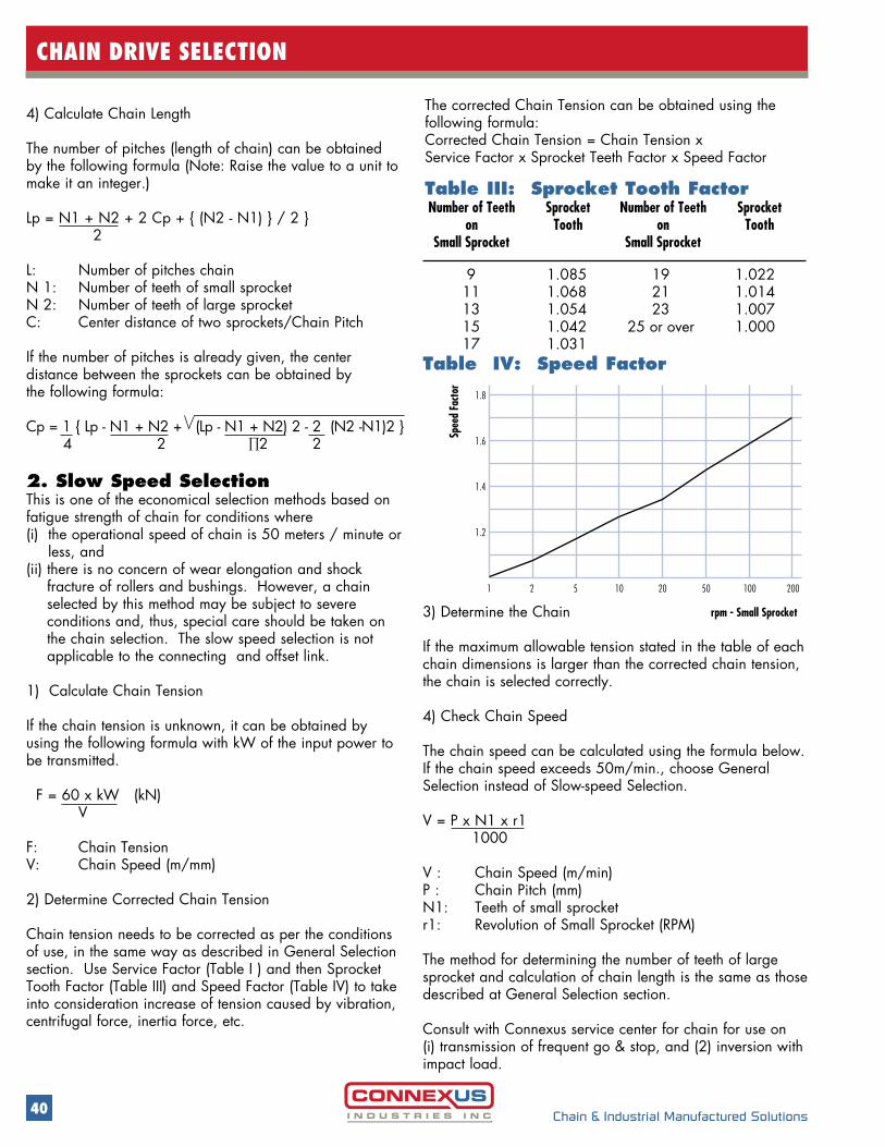
Table III: Sprocket Tooth Factor
9 1.085 19 1.022 11 1.068 21 1.014 13 1.054 23 1.007 15 1.042 25 or over 1.000 17 1.031
Number of Teeth on
Small Sprocket
Sprocket Tooth
Sprocket Tooth
Number of Teeth on
Small Sprocket
3) Determine the Chain
If the maximum allowable tension stated in the table of each chain dimensions is larger than the corrected chain tension, the chain is selected correctly.
4) Check Chain Speed
The chain speed can be calculated using the formula below. If the chain speed exceeds 50m/min., choose General Selection instead of Slow-speed Selection.
V = P x N1 x r1 1000
V : Chain Speed (m/min)P : Chain Pitch (mm)N1: Teeth of small sprocketr1: Revolution of Small Sprocket (RPM)
The method for determining the number of teeth of large sprocket and calculation of chain length is the same as those described at General Selection section.
Consult with Connexus service center for chain for use on(i) transmission of frequent go & stop, and (2) inversion with impact load.
Table IV: Speed Factor
1.8
1.6
1.4
1.2
1 2 5 10 20 50 100 200
rpm - Small Sprocket
Spee
d Fa
ctor

41Chain & Industrial Manufactured Solutions
CHAIN DRIVE SELECTION
6
Number of chain strands
5 4 3 2 110 20 30 40 50 60 70 100 200 300 500 700 1000 2000 3000 5000 7000 10000
20
40
30
50 60 70
200
300 500700 10001000
1000
700
500
300
200
100
70
50
40
30
20
10
7
5
4
3
2
1
0.7
0.5
0.4
0.3
700
500
300
200
100
70
50
40
30
20
10
7
5
4
3
2
1
0.7
0.5
0.4
0.3
700
500
300
200
100
70
50
40
30
20
10
7
5
4
3
2
1
0.7
0.5
0.4
0.3
0.2
500
300
200
300
200
100
70
50
40
30
20
10
7
5
4
3
2
1
0.7
0.5
0.4
0.3
0.2
0.1
90
9.08.07.06.05.0
4.0
3.0
2.0
1.00.90.80.70.60.5
0.4
0.3
0.2
0.1
80
10
240 200
180
160140
120
80
6050
40
35
25
100
100
70
50
40
30
20
10
7
5
4
3
2
1
0.7
0.5
0.4
0.3
0.2
100
R.P.M. - Small Sprocket
How to use this table:
For easy selection of chain and sprocket, check the intersection of revolution per minute (RPM) of design kW (vertical axis) and the small sprocket (horizontal axis).
Example:Assume design kW is 5kW and the RPM of the small sprocket is 100. By taking the intersection point of this design kW value of 5kW and RPM value is 100, one can derive # 80 ANSI chain and a sprocket of 16 Teeth from the chart.
42 Chain & Industrial Manufactured Solutions
CHAIN DRIVE SELECTION
The corrected Chain Tension can be obtained using the following formula:Corrected Chain Tension = Chain Tension x Service Factor x Sprocket Teeth Factor x Speed Factor
Table III: Sprocket Tooth Factor
9 1.085 19 1.022 11 1.068 21 1.014 13 1.054 23 1.007 15 1.042 25 or over 1.000 17 1.031
Number of Teeth on
Small Sprocket
Sprocket Tooth
Sprocket Tooth
Number of Teeth on
Small Sprocket
Table IV: Speed Factor
3) Determine the Chain
If the maximum allowable tension stated in the table of each chain dimensions is larger than the corrected chain tension, the chain is selected correctly.
4) Check Chain Speed
The chain speed can be calculated using the formula below. If the chain speed exceeds 50m/min., choose General Selection instead of Slow-speed Selection.
V = P x N1 x r1 1000
V : Chain Speed (m/min)P : Chain Pitch (mm)N1: Teeth of small sprocketr1: Revolution of Small Sprocket (RPM)
The method for determining the number of teeth of large sprocket and calculation of chain length is the same as those described at General Selection section.
Consult with CONNEXUS service center for chain for use on(i) transmission of frequent go & stop, and (2) inversion with impact load.
1.8
1.6
1.4
1.2
1 2 5 10 20 50 100 200
rpm - Small Sprocket
Spee
d Fa
ctor
4) Calculate Chain Length
The number of pitches (length of chain) can be obtained by the following formula (Note: Raise the value to a unit to make it an integer.)
Lp = N1 + N2 + 2 Cp + { (N2 - N1) } / 2 } 2
L: Number of pitches chainN 1: Number of teeth of small sprocketN 2: Number of teeth of large sprocketC: Center distance of two sprockets/Chain Pitch
If the number of pitches is already given, the center distance between the sprockets can be obtained by the following formula:
Cp = 1 { Lp - N1 + N2 + (Lp - N1 + N2) 2 - 2 (N2 -N1)2 } 4 2 ∏2 2
2. Slow Speed SelectionThis is one of the economical selection methods based on fatigue strength of chain for conditions where (i) the operational speed of chain is 50 meters / minute or
less, and (ii) there is no concern of wear elongation and shock fracture
of rollers and bushings. However, a chain selected by this method may be subject to severe conditions and, thus, special care should be taken on the chain selection. The slow speed selection is not applicable to the connecting and offset link.
1) Calculate Chain Tension
If the chain tension is unknown, it can be obtained by using the following formula with kW of the input power to be transmitted.
F = 60 x kW (kN) V
F: Chain TensionV: Chain Speed (m/mm)
2) Determine Corrected Chain Tension
Chain tension needs to be corrected as per the conditions of use, in the same way as described in General Selection section. Use Service Factor (Table I ) and then Sprocket Tooth Factor (Table III) and Speed Factor (Table IV) to take into consideration increase of tension caused by vibration, centrifugal force, inertia force, etc.
43Chain & Industrial Manufactured Solutions
WARNING
WARNING
Safety Precautions in installing, removing, lubricating or servicing a chain system:
• There should be guards provided on all chain and sprocket installations in accordance with existing applicable safety standards.
• Take care that power is turned off before installing, removing, lubricating or servicing a chain system.
• Always wear safety glasses to prevent injury to eyes.
• Wear appropriate protective clothing; i.e., hats, gloves and safety shoes.
• Always be sure to have properly working tools and follow directions for their proper use.
• Always loosen tensioning devices.
• Always support the chain to prevent uncontrolled movement of the chain and/or parts.
• Discard damaged chain or parts and do not attempt to re-use chain or parts or their individual components.
• Failure to use these safety instructions may result in serious injury or death.
Limited Warranty Disclaimer and Exclusions
The seller warrants that the Goods and/or Service will be free from defects in material workmanship for a period of three months from date of delivery, or an agreed upon established time period at time of order.
The sole obligation of CONNEXUS INDUSTRIES INC. or any associated companies here after called “The Company”, under this Limited Warranty shall be to repair or replace or have it’s Authorized Distributor repair or replace any defective products within 45 business days of a complaint communicated in writing to “The Company”. Except as expressly provided herein, “The Company” shall not liable for the breach of any warranty, express or implied, including without liability arising out of merchantability of fitness for a particular purpose, or for any damages or other liability arising out of or in connection with customers’ use of supplier products or “The Company” or the authorized distributor designing, manufacturing or selling supplied products. In no event shall “ The Company” be liable for direct, special, incidental or consequential damages, including without limitation lost sales or profit, lost production or output, injury to property or reputation, or any other damages whether arising in contract or tort or otherwise (whether or not attributable to the fault or negligence of “The Company”). Under no circumstances shall any recovery of any kind against “The Company” be greater in amount than the price of the products and/or service to end user.
NOTE: Products that have been modified and/or altered from their original state without expressed written consent of “The Companies” Representative shall void this and any other warranty written or expressed. All returned materials shall be evaluated by “The Companies” engineering and sales staff prior to credit and rework. Product being returned for evaluation must include a valid “Returned Goods Authorization” number (RGA#) RGA Number added as a procedure with ISO 9001.2008 Certification Oct 19, 2015.
CONTACT US
www.connexusindustries.com
27474 Gloucester Way, Langley BC, Canada V4W 4A1t 604.882.1602 f 604.882.1603 toll free 1.800.324.1244
Langley CAD HQ
1892 1’Ere Rue, St Romuald, QC, Canada G6W 5M6t 418.834.5116 f 418.834.5901 toll free 1.888.650.6090
Quebec Branch
9525 SW Commerce Circle, Wilsonville, OR, USA 97070t 503.222.9992 f 503.222.0073 toll free 1.800.367.9992
Portland USA HQ
ed in
Cana
da
11163411 Novis Pointe, Acworth, GA, USA 30101
t 678-797-0777 f 678.797.5554 toll free 1.877.941.1500Atlanta Branch
![Section 2 Galvanised Malleable Iron Pipe · PDF file 29 GALVANISED MALLEABLE IRON PIPE FITTINGS [2] Galvanised Malleable Hexagon Bush Galvanised Malleable Hexagon Bush AAP CODE](https://img.pdfslide.us/doc/110x75/5aa732b57f8b9a6d5a8bfbda/section-2-galvanised-malleable-iron-pipe-29-galvanised-malleable-iron-pipe-fittings.jpg)
![Section 2 Galvanised Malleable Iron Pipe Fittings · 29 GALVANISED MALLEABLE IRON PIPE FITTINGS [2] Galvanised Malleable Hexagon Bush Galvanised Malleable Hexagon Bush AAP CODE](https://img.pdfslide.us/doc/110x75/5b96177509d3f2ea5c8cd0dc/section-2-galvanised-malleable-iron-pipe-fittings-29-galvanised-malleable-iron.jpg)