Embed Size (px)
Citation preview
Journal of Energy and Power Engineering 11 (2017) 363-371 doi: 10.17265/1934-8975/2017.06.001
Rocket Propulsion Powered Using a Gyrotron
Masafumi Fukunari1, Kimiya Komurasaki2, Yusuke Nakamura3, Yasuhisa Oda4 and Keishi Sakamoto4
1. Research Center for Development of Far-Infrared Region, University of Fukui, Fukui 910-8507, Japan
2. Department of Aeronautics & Astronautics, University of Tokyo, Bunkyo, Tokyo 113-8656, Japan
3. Graduate School of Frontier Sciences, University of Tokyo, Kashiwa, Chiba 277-8561, Japan
4. National Institutes for Quantum and Radiological Science and Technology, Naka, Ibaraki 311-0193, Japan
Received: April 28, 2017 / Accepted: May 10, 2017 / Published: June 30, 2017. Abstract: This paper presents a review of a beamed energy propulsion rocket, the Microwave Rocket, which produces propulsive thrust from millimeter-wave beams transferred from the ground. The thrust is generated through millimeter-wave discharge driven in a cylindrical thruster. As a high-power millimeter-wave generator, a Gyrotron is promising as the beam source. The salient benefit of Microwave Rockets is the resultant drastic cost reduction of mass transportation into space. We have already conducted launch experiments and have achieved continuous thrust generation under multi-pulse operation. Recently, a long-distance beam transfer system has been developed. Ignition tests have been conducted. The physics of the millimeter-wave discharge remain unclear. Additional studies using experimentation and calculations must be conducted to optimize the thrust generation. Key words: Beamed energy propulsion, microwave discharge, wireless power transfer, gyrotron.
Acronyms/Abbreviations
MSD Microwave supported detonation
LSD Laser supported detonation
WPT Wireless power transfer
BEP Beamed energy propulsion
QST National Institutes for Quantum and radiological Science and Technology
C-J Chapman-Jouguet
CFD Computational fluid dynamics
1. Introduction
In conventional cars and spacecraft, fuel is always
kept on-board. Accordingly, it must increase
concomitantly with increased load mass, velocity
increment, and travel distance. Actually, fuel is
necessary to move the fuel itself. Therefore, the
payload ratio is limited. For example, assuming that a
chemical rocket is launched into geostationary earth
orbit, the payload mass is only 1% of the total mass, at
Corresponding author: Masafumi Fukunari, Ph.D.,
specially appointed assistant professor, research fields: millimeter wave, millimeter wave discharge, gyrotron, beamed energy propulsion.
maximum. The WPT, which transfers energy by an
electromagnetic-wave beam, can be a promising
solution to the tradeoff relation. The WPT propulsion
rocket concept, called the BEP launcher, was
proposed by Kantrowitz in 1972 [1]. Many studies of
BEP launchers have been conducted using laser or
microwave beams [2-4].
The Microwave Rocket is a BEP launcher using a
megawatt class millimeter-wave oscillator Gyrotron.
The Gyrotron, developed as a heating device for nuclear
fusion plasma, has already achieved high-power,
long-pulse, high-efficiency operation such as 1 MW/800
s/55% electrical efficiency at the National Institutes
for Quantum and Radiological Science and Technology
(QST/JAEA) [5]. Generally, “microwaves” are 3-30
GHz electromagnetic waves; the 30-300 GHz frequency
band is called “millimeter-wave”. However, in the
field of BEP, the frequency bands are often categorized
only as laser or microwave. Moreover, “microwave”
has higher name recognizability than “millimeter
wave” does. These are reasons why we have
designated the BEP launcher as a Microwave Rocket.
D DAVID PUBLISHING

Rocket Propulsion Powered Using a Gyrotron
364
Microwave Rockets can drastically reduce mass
transportation costs to space. The bottleneck hindering
space exploration is the huge transportation cost
attributable to chemical rockets. Conventional rockets
require huge amounts of fuel and propellant. The fuel
consumption is determined by the exhaust velocity
(specific impulse), which is accordingly limited by the
chemical energy per unit mass of fuel. The fuel
consumption of the current rocket has already reached
the theoretical limits. Microwave Rockets do not have
the limitation because the energy source is separate
from the rocket. Furthermore, Microwave Rockets can
use atmospheric air as a propellant by using an
air-breathing system. In such cases, no on-board
propellant is needed. The payload ratio can be much
higher than those of chemical rockets. Furthermore,
the Microwave Rocket engine structure is theoretically
simple because the thruster acquires high pressure by
shock wave compression using the MSD without a
complex and expensive turbo-pump system.
Consequently, the manufacturing cost can be low.
Ground facilities include a substantial number of
gyrotron and energy storage facilities. Although the
construction cost is dominant in all costs, the costs can
be amortized by repeated launches.
Experimental studies of Microwave Rockets have
been conducted using a megawatt class gyrotron at the
National Institutes for Quantum and radiological
Science and Technology (QST). Numerical studies of
millimeter wave discharge have been conducted to
investigate ionization mechanisms. As described
herein, we describe the thrust generation process, a
launch demonstration of the rocket, and numerical
computation of millimeter wave discharge as a review
of Microwave Rocket studies.
2. Thrust Generation Processes Using MSD
Fig. 1 presents the thrust generation process. The
thruster is a cylindrical tube with one side closed. A
parabolic mirror is mounted at the closed end as
an ignitor. The parabolic mirror focuses the incident
Fig. 1 Thrust generation process.
beam. Then the discharge is ignited at the focal point.
A screw is often set at the focal point to support the
ignition in experiments using a model rocket. The
ionization front of the discharge propagates toward the
beam source, absorbing the millimeter-wave energy.
A shock wave is driven by the discharge. High
pressure behind the shock wave imparts the thrust
impulse to the thruster. Impulsive thrust is
determined by the time integral of the pressure at
the closed end during engine cycle time .
(1)
Consequently, the closed end is called the thrust
wall. represents the area of the thrust wall. The
ratio of the on the incident energy is called the
momentum coupling coefficient Cm, which is equal to
the ratio of the time averaged thrust on average
power .
(2)
In Eq. (2), denotes the peak power; is the
pulse duration. The BEP launcher thrust performance
is usually evaluated by Cm.
Rocket Propulsion Powered Using a Gyrotron
365
The phenomenon is called MSD by analogy with
chemical detonation. When the MSD arrives at the
open end, the beam must be cut off to avoid energy
loss. An expansion wave then starts to propagate from
the open end to the thrust wall. The pressure at the
thrust wall is maintained as high until the expansion
wave reaches the thrust wall and the thruster acquires
an impulsive thrust. Negative gauge pressure is then
generated at the thrust wall because of the reflection
of the expansion wave. An air-breathing system such
as a reed valve mounted at thruster side wall refreshes
the inside gas. The Microwave Rocket is accelerated,
repeating this engine cycle.
3. Launch Experiments
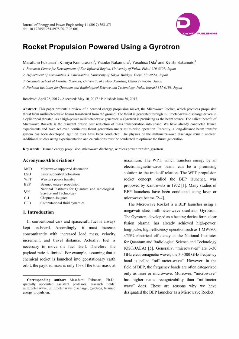
Launch experiments have been conducted with a
gyrotron in QST. The first launch experiment was
conducted in 2003 by 930 kW single pulse operation.
Although the model rocket mass was only 9.5 g, a model
rocket was launched to 2 m. We confirmed the thrust
generation [6]. In 2009, continuous thrust generation
was obtained under multi-pulse operation [7] in a ground
test. Subsequently, launch experiments were conducted
under multi-pulse operations (Fig. 2 [8]). For launch
experiments, the beam power, pulse duration, and
pulse repetition frequency were, respectively, 600 kW,
1 ms, and 100 Hz. The 109 g model rocket consisted
of a conical reflector and a cylindrical aluminum body
without the air-breathing system. The respective
diameter and length of the model rocket were 100 mm
and 300 mm. As a result, the model rocket was launched
to 1.2 m. However, when the beam transmission distance
exceeded 2 m, the generated thrust was insufficient for
launching because of the beam divergence [8]. In
2011, large thrust of 30 N was achieved using high
power and high-frequency repetitive operation [9].
Table 1 presents results related to the thrust performance.
The achievement of 30 N thrust indicates that a kg
class model rocket can be launched. Therefore, we set
the next goal as a kg class model rocket launching to
10 m altitude.
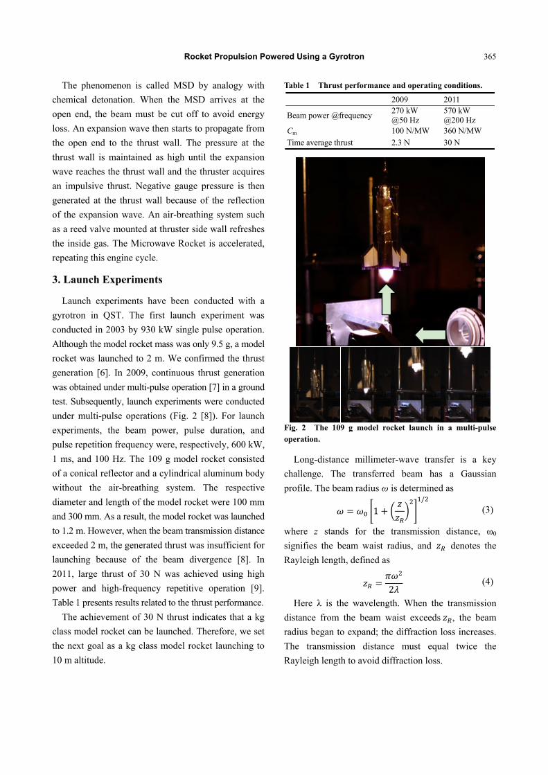
Table 1 Thrust performance and operating conditions.
2009 2011
Beam power @frequency 270 kW @50 Hz
570 kW @200 Hz
Cm 100 N/MW 360 N/MW
Time average thrust 2.3 N 30 N
Fig. 2 The 109 g model rocket launch in a multi-pulse operation.
Long-distance millimeter-wave transfer is a key
challenge. The transferred beam has a Gaussian
profile. The beam radius ω is determined as
1/
(3)
where z stands for the transmission distance, ω0
signifies the beam waist radius, and denotes the
Rayleigh length, defined as
2 (4)
Here λ is the wavelength. When the transmission
distance from the beam waist exceeds , the beam
radius began to expand; the diffraction loss increases.
The transmission distance must equal twice the
Rayleigh length to avoid diffraction loss.

Rocket Propulsion Powered Using a Gyrotron
366
Consequently, a millimeter-wave transfer system
was developed as depicted in Fig. 3. The
millimeter-wave beam generated by the 170 GHz
high-power gyrotron was transmitted through the 63.5
mm corrugated waveguide. The transmission mirror
system was composed of a couple of offset parabolic
mirrors. It extended the beam radius from 20.4 to 120
mm. was increased accordingly from 0.7 m to
25.7 m. A parabolic mirror with 280 mm-diameter and
a 60 mm-diameter mirror were installed into the
thruster to convert the beam profile and to guide it
into the thruster tube. The incident beam power and
pulse duration were 400 kW and 0.4 ms, respectively.
Plasma was ignited in the thruster at 1 m, 3 m, and 5
m distance from the transmission mirror system. The
time averaged thrust was measured from the thruster
motion. As a result, 3.0 N thrust force was obtained at
100 Hz repetition frequency [8, 10].
A tapered-tube concentrator has also been proposed
to receive the expanded beam. Fig. 4 shows that the
concentrator directly connected to the model rocket
and received the incident beam, guiding it into the
(a) Model rocket operation
(b) Transmission mirror system (c) Receiver mirror system
Fig. 3 Long-distance millimeter-wave transfer system with the receiving mirror system.
Fig. 4 Long-distance millimeter-wave transfer system with the tapered tube concentrator.
model rocket. In high-power experiments, plasma
ignition and ionization front propagation with the
transmission system were confirmed when using
incident power of 630 kW. Thrust generation was
achieved [11, 12].
In multi-pulse operation, plasma remains even after
the beam is turned off. Especially, in the concentrator
where the beam radius and the plasma radius expand,
the plasma remains for a long time: more than 10 ms.
The discharge was ignited with the remaining plasma.
Thrust generation was impeded because the plasma
outside the thruster tube does not contribute to thrust
generation. These abnormal ignitions also occur by the
edges or internal structures of the thruster tube.
Prevention or quenching of the abnormal ignitions
will be examined as a challenge for future study.
4. Microwave Supported Detonation
Propagation of the ionization front absorbing the
incident beam energy accompanying a shock wave is
called detonation, as described above. If the incident
beam is a laser, then the detonation is called LSD.
Raizer et al. [13] have conducted pioneering studies in
LSD. Several studies have examined LSD
experimentally and computationally [14, 15 and
Model rocket
Concentrator
Transmission mirror
Corrugated waveguide
Output window

Rocket Propulsion Powered Using a Gyrotron
367
references therein]. In MSD, Oda et al. [16-19]
reported experimental observations using a high-speed
camera at 170 GHz. Oda et al. had also measured the
propagation velocity of the ionization front as a
function of the incident beam power. The propagation
velocity was found to be proportional with the
incident power. Fig. 5 shows that the tendency is
completely different from that of the LSD.
Actually, one can apply the detonation theory to the
MSD only when the propagation velocity of the
ionization front is the same as that of the shock wave.
In the 170 GHz case, when the peak beam power
density was lower than about 200 kW/cm2, the
propagation velocity of the shock wave was higher
than that of the ionization front. The distance between
the shock wave and ionization front then increases by
time. From analogy of the chemical detonation theory,
this condition is sometimes called MSC (microwave
supported combustion). However, the condition is
completely separate from combustion. The theory is
inapplicable. In addition, the propagation velocity of
the ionization front must be higher than that at the C-J
condition.
In the one-dimensional stationary theory assuming
that the control volume is fixed with the detonation
front, the system of equations is described by the
equation of continuity as
(5)
the equation of the momentum conservation,
(6)
the equation of the energy conservation,
C12
C12
(7)
and the equation of gas state,
. (8)
Here, Cp, p, R, T, u, q, and ρ respectively represent
the specific heat at constant pressure, pressure, gas
constant, temperature, flow velocity, absorbed
energy per unit mass, and density. Indices 1 and 2
respectively denote conditions in front of the
shock wave and behind the detonation. is the
Fig. 5 Propagation velocities of the ionization front at respective beam power densities.
propagation velocity because the coordinate is fixed
with the detonation. q is
(9)
where, is the absorption coefficient and is the
beam power density.
The system of equations includes parameters p, T, ρ,
u, and q. In the chemical detonation case, q is a
constant determined by the fuel and equivalence ratio.
However, in the case of MSD, the number of
equations is insufficient to solve the system. Raizer et
al. [13] have proposed a simple model for LSD
assuming that the internal energy and pressure in front
of the LSD are negligible compared with those behind
the LSD. Shimada et al. [20] investigated the MSD
condition at each propagation velocity fixing the
absorbed energy. However, new equations for
propagation velocity and absorption coefficient as a
function of incident energy, beam frequency, gas
pressure, and gas species are necessary to solve the
system.
5. Millimeter Wave Discharge Structure
In the time-integral image of the MSD, fine
filament structures can be observed. This structure is
self-organized and determined by nonlinear dynamics.

Rocket Propulsion Powered Using a Gyrotron
368
Discharge at the microwave frequency band has
been studied since 1940. The fundamental physics has
been clarified. However, the discharge in millimeter
wave frequency band has recently become available
because of gyrotron development. Early experiments
examining this discharge using a gyrotron were
conducted in the 1980s. Vikharev et al. [21] reported
the pressure dependence of helium and nitrogen gas
discharge generated by a focused 37.5 GHz millimeter
wave (λ = 8 mm wavelength). Hidaka et al. [22]
investigated the evolution of the filament using a
mirror to focus 110 GHz millimeter wave beams; they
asserted that filaments are generated by a standing
wave.
A millimeter-wave discharge can be categorized as
either sub-critical or overcritical depending on the
incident beam power density. In the overcritical region,
the incident beam power density closes to the
ionization threshold of the gas. A standing-wave
generated by the incident and a reflected beam from
the ionization front contribute to the structure. The
local beam power density at the standing wave
exceeds the ionization threshold, resulting in new
filament ignition. The process occurs repeatedly along
the beam pulse width. Consequently, the ionization
front propagates toward the beam source. The
propagation velocity was measured as 105 m/s to 104
m/s in Hidaka’s experiment. The pitch of each
filament is slightly shorter than one-quarter of the
wavelength (λ/4 structure) because of the skin depth
of the plasma. The discharge also stretches along the
electric field of the incident beam. Consequently, in
the (E, k) plane, which contains the wave vector k
parallel to the electric field vector E, a filament array
is generated, whereas a lattice-like pattern appeared in
the (H, k) plane, which contains k parallel to the
magnetic field vector H. The overcritical condition
has been reproduced numerically by Bouef et al. [23],
who calculated the electromagnetic field using the
FDTD (finite-difference time-domain) method and
induced the electron number density by the
diffusion equation of
∆ (10)
where,
1 (11)
And signifies the attachment frequency,
denotes the critical intensity, is the local
effective electric field intensity, represents the
effective diffusion coefficient, and stands for a
numerical constant.
The millimeter-wave discharge in the MSD is
expected to be in the sub-critical condition, for which
the incident beam power density is much lower than
the ionization threshold. The ionization front cannot
jump. Therefore, the λ/4 is not formed. Instead,
granular plasmas propagate toward the beam source.
The trajectories form stream lines, also known as
filaments, in the time-integral image (Fig. 6). The
typical propagation velocity is 102 m/s. Few studies
have examined the sub-critical condition. Oda’s
experiments contributed to the sub-critical condition,
as described above. Bratman et al. [24] reported the
discharge at 0.55 THz. Experiments conducted by
Bogatov et al. [25] might account for the sub-critical.
VoskoboÏnikova et al. pointed out that, in the
sub-critical condition, the time scale of the discharge
evolution is comparable to the gas-dynamics process.
In addition, reduction of the gas (neutral particle)
density in the discharge because of Joule heating
contributes to the ionization process [26]. They
reproduced spark streamer discharges in the
subcritical region. The absolute value of the local
electric field intensity divided by the number density
of the gas |E|/n was calculated. When |E|/n exceeds the
critical value (|E|/n)c at the streamer head, the number
of electrons increases because of the ionization.
Takahashi et al. [27] calculated the discharge
and deduced the thrust performance at respective
pressures. Takahashi et al. also proposed the use of
ECH (electron cyclotron heating) on-board an external

Rocket Propulsion Powered Using a Gyrotron
369
Fig. 6 Experimental setup and images of the filament structure.
Fig. 7 Numerical computation result of the number density of the electron.
magnet. They showed a drastic increase in the thruster
performance using ECH [27].
Reconsidering the ionization model in the source
term presents another challenge. Fig. 7 depicts a
numerical computation result. The source term was
modified artificially. The propagation of granular
plasma was reproduced [28].
6. Microwave Rocket Feasibility Studies
Thrust generation and multi-pulse operation have
already been demonstrated through launch experiments.
From these launch experiments, the momentum
coupling coefficient of Microwave Rockets is
expected to be close to 300 N/MW. Assuming beam
power of 1 MW and a duty cycle of 0.2 for the
millimeter wave beam pulse, the Microwave Rocket
acquires the time average thrust of 60 N. In actual
flight, millimeter wave attenuation by atmospheric air
Fig. 8 Schematic image of the Japanese H-IIB replaced the first stage engine and solid rocket boosters by the Microwave Rocket.
and a decrease in air density affects the thrust
performance. Consequently, the Microwave Rocket
launch capability is expected to be 1-2 kg/MW.
Some Microwave Rocket feasibility studies have
been done. For a case in which the first stage engine
and solid rocket boosters of Japanese H-IIB are
replaced by a Microwave Rocket, the payload ratio is
expected to be increased from 3.45% to 15.5%. Fig. 8
portrays the model rocket. The total mass was reduced
from 531 tons to 122.2 tons. The required beam power
was estimated as 188 GW to carry a 19 tons payload
to LEO. The resulting launch cost per unit payload
becomes lower than that of a conventional H-IIB at
about 20 launches. At one thousand launches, the
construction cost of the beam facility becomes fully
amortized. The cost reduction reached 77% in the
analysis [29].
Kakinuma et al. [31] proposed a TSTO
(two-stage-to-orbit transporting) launch system with a
Microwave Rocket first stage and a Microwave
Thermal Rocket second stage, as proposed by Parkin
et al. [30]. The wet mass of the whole rocket was
assumed as 50 kg. For the first stage task, the
Microwave Rocket brings a Microwave Thermal
Rocket to a high altitude instead of the UAV
(unmanned aerial vehicle). The Microwave Rocket is
simpler, faster, and reaches a higher altitude at higher
speed. Additionally, they presented a new trajectory
that eliminates power beaming at low elevation angles,
which improves system performance. The whole

Rocket Propulsion Powered Using a Gyrotron
370
launch system has remarkable performance of a three
times larger payload fraction. The launch cost per unit
mass of payload is only one quarter that of the case of
the UAV. These differences are expected to be much
more pronounced in a larger scale launch system. As a
result, to demonstrate an 8 kg satellite launch, beam
facility construction cost of $490 M, vehicle cost of
$46 k, and electricity cost of $150 were expected [31].
7. Conclusions
Microwave Rockets are promising candidates as
breakthroughs to reduce mass transportation costs to
the space drastically. However, numerous challenges
remain, which include the physics of MSD and its
application to thrust performance optimization,
air-breathing systems (which are not described herein),
long-distance beam power transportation, and
abnormal ignition. In addition, feasibility studies
indicate a huge initial cost for ground facilities.
Nevertheless the cost estimations might be optimistic.
Although the construction costs can be amortized,
reduction of costs will be necessary, especially in
early stages. Furthermore, one must consider
regulations of radio use in Japan. Currently, of course,
no frequency band is allowed to irradiate such a high
power beam externally. These are reasons why the
Microwave Rocket remains interesting as a challenge
for future research efforts.
Acknowledgements
This work was supported by a Grant-in-Aid for
Scientific Research (S), No. 15H05770.
References
[1] Kantrowitz, A. 1972. “Astronaut.” Aeronaut 10: 74-6. [2] Phipps, C., Birkan, M., Bohn, W., Eckel, H.-A., Horisawa,
H., Lippert, T., Michaelis, M., Rezunkov, Y., Sasoh, A., Schall, W., Scharring, S., and Sinko, J. 2010. “Review: Laser-Ablation Propulsion.” Journal of Propulsion and Power 26 (4): 609-37.
[3] Komurasaki, K., and Wang, B. 2010. Encyclopedia of Aerospace Engineering. Hoboken: John Wiley & Sons Ltd., 1351.
[4] Myrabo, L. 2001. “World Record Flight of Beam-Riding Rocket Lightcraft: Demonstration of ‘Disruptive’ Propulsion Technology.” In Proceedings of the 37th AIAA/ASME/SAE/ASEE Joint Propulsion Conference, Salt Lake City, US.
[5] Sakamoto, K., Kasugai, A., Takahashi, K., Minami, R., Kobayashi, N., and Kajiwara, K. 2007. “Achievement of Robust High-efficiency 1|[thinsp]|MW Oscillation in the Hard-Self-Excitation Region by a 170|[thinsp]|GHz Continuous-wave Gyrotron.” Nature Physics 3 (6): 411-4.
[6] Nakagawa, T., Mihara, Y., Komurasaki, K., Takahashi, K., Sakamoto, K., and Imai, T. 2004. “Propulsive Impulse Measurement of a Microwave-Boosted Vehicle in the Atmosphere.” Journal of Spacecraft and Rockets 41 (1): 151-3.
[7] Oda, Y., Shibata, T., Komurasaki, K., Takahashi, K., Kasugai, A., and Sakamoto, K. 2009. “Thrust Performance of Microwave Rocket under Repetitive-Pulse Operation.” Journal of Propulsion and Power 25 (1): 118-22.
[8] Yamaguchi, T., Komurasaki, K., Oda, Y., Kajiwara, K., Takahashi, K., and Sakamoto, K. 2011. “Millimeter-Wave Beam Conversion with Quasi-Optical Mirrors for Microwave Rocket Launch Demonstration.” AIP Conference Proceedings 1402 (1): 467-77.
[9] Komatsu, R., Yamaguchi, T., Oda, Y., Saitoh, S., Fukunari, M., Komurasaki, K., Kajiwara, K., Takahashi, K., and Sakamoto, K. 2012. “Thrust Augmentation of Microwave Rocket with High-Power and High-Duty-Cycle Operation.” Journal of the Japan Society for Aeronautical and Space Science 60 (6): 235-7 (in Japanese).
[10] Oda, Y., Yamaguchi, T., Shimada, Y., Komurasaki, K., Kajiwara, K., Takahashi, K., and Sakamoto, K. 2010. “Study of High-Power Millimeter-Wave Beam Transmission for Microwave Beaming Propulsion.” In Proceedings of the 35th International Conference on Infrared, Millimter, and Terahertz Waves, Rome, Italy.
[11] Fukunari, M., Wongsuryrat, N., Yamaguchi, T., Nakamura,
Y., Komurasaki, K., and Koizumi, H. 2017. “Design of a
Millimeter-Wave Concentrator for Beam Reception in
High-Power Wireless Power Transfer.” Journal of
Infrared, Millimeter, and Terahertz Waves 38 (2): 176-90.
[12] Fukunari, M., Yamaguchi, T., Saitoh, S., Asai, K., Kurita,
S., Komurasaki, K., Oda, Y., Kajiwara, K., Takahashi, K.,
and Sakamoto, K. 2013. “Thrust Performance and Plasma
Generation of Microwave Rocket with Microwave Beam
Space Transmission System.” In Proceedings of the IEEE
Pulsed Power & Plasma Science Conference, San
Francisco, California, USA.
[13] Raizer, Y. P. 1965. “Breakdown and Heating of Gases
with a Laser Light Pulse.” Sov. Phys. JETP 21 (5):
1009-17.

Rocket Propulsion Powered Using a Gyrotron
371
[14] Shimamura, K., Matsui, K., Ofosu, J. A., Yokota, I., and Komurasaki, K. 2017. “Mode Transition of Plasma Expansion for Laser Induced Breakdown in Air.” Applied Physics Letters 110: 134104.
[15] Mori, K., Komurasaki, K., and Arakawa, Y. 2006. “Threshold Laser Power Density for Regime Transition of a Laser Absorption Wave in a Reduced-Density Air Atmosphere.” Applied Physics Letters 88 (12): 59-104.
[16] Oda, Y., Komurasaki, K., Kasugai, A., and Sakamoto, K. 2006. “Plasma Generation Using High-Power Millimeter-Wave Beam and Its Application for Thrust Generation.” Journal of Applied Physics 100 (11): 32-156.
[17] Oda, Y., Komurasaki, K., Takahashi, K., Kasugai, A., Imai, T., and Sakamoto, K. 2007. “Plasma Generation at Atmospheric Pressure Using a High-Power Microwave Beam and Its Application to Rocket Propulsion.” Electrical Engineering in Japan 161 (2): 1-7.
[18] Oda, Y., Yamaguchi, T., Shiraishi, Y., Komurasaki, K., Kajiwara, K., Takahashi, K., Kasugai, A., and Sakamoto, K. 2011. “A One-Dimensional Propagation of Shock Wave Supported by Atmospheric Millimeter-Wave Plasma.” Journal of Infrared, Millimeter and Terahertz Waves 32 (6): 877-82.
[19] Oda, Y., Kajiwara, K., Takahashi, K., Kasugai, A., and Sakamoto, K. 2008. “Development of Filamentary Structure of Atmospheric Breakdown on 170 GHz Gaussian Beam.” In Proceedings of the IEEE 35th International Conference on Plasma Science, Karlsruhe, Germany.
[20] Shimada, Y., Shibata, T., Yamaguchi, T., Oda, Y., Kajiwara, K., Takahashi, K., Kasugai, A., Sakamoto, K., Komurasaki, K., and Arakawab, Y. 2010. “Propagating Structure of a Microwave Driven Shock Wave Inside a Tube.” AIP Conference Proceedings 1230 (1): 366-76.
[21] Vikharev, L., Gil’denburg, V. B., Golubev, S. V., Eremin, B. G., Ivanov, O. A., Litvak, A. G., Stepanov, A. N., and Yunakovskii, A. D. 1988. “Nonlinear Dynamics of a Freely Localized Microwave Discharge in an Electromagnetic Wave Beam.” Sov. Phys. JETP 67 (4): 724-8.
[22] Hidaka, Y., Choi, E. M., Mastovsky, I., Shapiro, M. A., Sirigiri, J. R., and Temkin, R. J. 2008. “Observation of Large Arrays of Plasma Filaments in Air Breakdown by 1.5-MW 110-GHz Gyrotron Pulses.” Physical Review
Letters 100 (3): 035003. [23] Boeuf, J. P., Chaudhury, B., and Zhu, G. Q. 2010.
“Theory and Modeling of Self-organization and Propagation of Filamentary Plasma Arrays in Microwave Breakdown at Atmospheric Pressure.” Physical Review Letters 104 (1): 015002.
[24] Bratman, V. L., Zorin, V. G., Kalynov, Y. K., Koldanov, V. A., Litvak, A. G., Razin, S. V., Sidorov, A. V., and Skalyga, V. A. 2011. “Plasma Creation by Terahertz Electromagnetic Radiation.” Physics of Plasma 18 (8): 083507.
[25] Bogatov, N. A., Bykov, Y. V., Venediktov, N. P., Goludev, S. V., Zorin, V. G., Eremeev, A. G., and Semenov, V. E. 1986. “Gasdynamic Propagation of a Nonequiliburium Micorwave Discharge.” Soviet Journal of Plasma Physics 12 (6): 416-20.
[26] VoskoboÏnikova, O. I., Ginzburg, S. L., D’yachenko, V. F., and Khodataev, K. V. 2002. “Numerical Investigation of Subcritical Microwave Discharges in a High-Pressure Gas.” Technical Physics 47 (8): 955-60.
[27] Takahashi, M., and Ohnishi, N. 2016. “Plasma Filamentation and Shock Wave Enhancement in Microwave Rockets by Combining Low-Frequency Microwaves with External Magnetic Field.” Journal of Applied Physics 120 (6): 40-2.
[28] Nakamura, Y., Fukunari, M., Yamaguchi, T., Komurasaki, K., and Koizumi, H. 2016. “Numerical Analysis of Comb Shaped Plasma Front Propagation in Millimeter-Wave Discharge under Atmospheric Pressure.” In Proceedings of the 47th AIAA Plasma Dynamics and Lasers Conference, AIAA Aviation and Aeronautics Forum and Exposition, Washington, DC, US.
[29] Fukunari, M., Arnault, A., Yamaguchi, T., and Komurasaki, K. 2014. “Replacement of Chemical Rocket Launchers by Beamed Energy Propulsion.” Applied Optics 53 (31): I16-22.
[30] Parkin, K. L. G., Didomenico, L., and Culick, F. C. 2004. “The Microwave Thermal Thruster Concept.” 2nd International Symposium on Beamed Energy Propulsion 702 (1): 418.
[31] Kakinuma, K., Fukunari, M., Yamaguchi, T., Nakamura, Y., Koizumi, H., Komurasaki, K., and Parkin, K. 2016. “Two-Stage-to-Orbit Transporting System Combining Microwave Rocket and Microwave Thermal Rocket for Small Satellite Launch.” Aerospace Technology Japan 14: 99-103.