Embed Size (px)
Citation preview
8/8/2019 Rocket Propulsion in Brief
http://slidepdf.com/reader/full/rocket-propulsion-in-brief 1/24
LOVELYPROFESSIONAL
UNIVERSTIY
TOPIC ± EXPLAIN HOW A ROCKET GETS LIFT FOR ITS PROPULSION, BRIEFLY EXPLAINS THE
PRINCIPLE OF ROCKET PROPULSION
NAME ± SAHIL VERMA
ROLL NO ± 27
REGD. NO ± 4180070111MECHANICAL
H47H1
SUBMITTED TO
LECT. MR. SRIDHAR
8/8/2019 Rocket Propulsion in Brief
http://slidepdf.com/reader/full/rocket-propulsion-in-brief 2/24
ACKNOWLDGEMENT
History of all great works is to witness that no great work was ever done without either the active
or passive support a personµs surrounding and one¶s close quarters. Thus it is not hard toconclude how active assistance from seniors. Could prohibitively impact the execution of a
project .I am highly thankful to our learned faculty Lect.Mr.Sridhar for his active guidancethroughout the completion of project. Last but not the least, I would also want extend my
appreciation to those who could not be mentioned here but here well played their role to inspire
the curtain.
WITH REGARDS:
SAHIL VERMA
(MECHANICAL)
8/8/2019 Rocket Propulsion in Brief
http://slidepdf.com/reader/full/rocket-propulsion-in-brief 3/24
TABLE OF CONTENT
Introduction
Principle
Thrust
Conservation of Momentum
Impulse & Momentum
Rocket Engines
Power Cycles
Engine Cooling
Solid Rocket Motors
8/8/2019 Rocket Propulsion in Brief
http://slidepdf.com/reader/full/rocket-propulsion-in-brief 4/24
Introduction to Rocket Propulsion
A rocket is an object that is propelled by the ejection of expanding gases that have been
generated from propellants, and that does not depend upon external sources. The engine containsits own propellant and obtains forward motion by reactive propulsion. Propulsion is obtained by
the ignition of the propellant, whereby the energy of explosion offers an opposite thrust thatcauses acceleration. Oxygen available in the atmosphere functions as the oxidizer for the fuel.
Gases at an extremely high temperature are produced by combustion of solid, liquid, or gaseousfuel in a combustion chamber. These gases pass through a nozzle, and thermal energy is
converted into kinetic energy, causing acceleration.
Principle
The principle of rocket propulsion depends on the following two laws: -
(i) Newton 's third law of motion
(ii) Law of conservation of momentum
We have already read about these laws, and now we will see how they can be applied for
propelling the rocket.
The motion of a rocket is an interesting application of Newton 's third law of motion &momentum principle. The rocket expels a jet of hot gases from its tail. This is say, an action
force. The jet of hot gases exerts a force on the rocket, propelling it forward; this is the reactionforce. From the momentum point of view, the hot gases acquire momentum in the backward
direction & the rocket acquires an equal amount of momentum in the forward direction.
The simplest example to understand the propulsion of rockets is that of a balloon.
A balloon shooting forward (when the mouth of the balloon filled with air is released) and a
rocket hurtling into space are propelled by similar forces. The air in a closed balloon exerts a
uniform outward force. But when air rushes out of its neck (similar to exhaust gases leavingrockets) disturbs this equilibrium. Thus an equal and opposite force is exerted on the surfaceopposite to the neck. This drives the balloon forward.
As we have seen in the previous section propellants are used to provide thrust to the rockets.
These propellants on burning produces large amount of gas, which are allowed to pass throughnozzle. On passing through the nozzle, high pressure is generated i.e. gas comes out with high
pressure.
8/8/2019 Rocket Propulsion in Brief
http://slidepdf.com/reader/full/rocket-propulsion-in-brief 5/24
Thrust
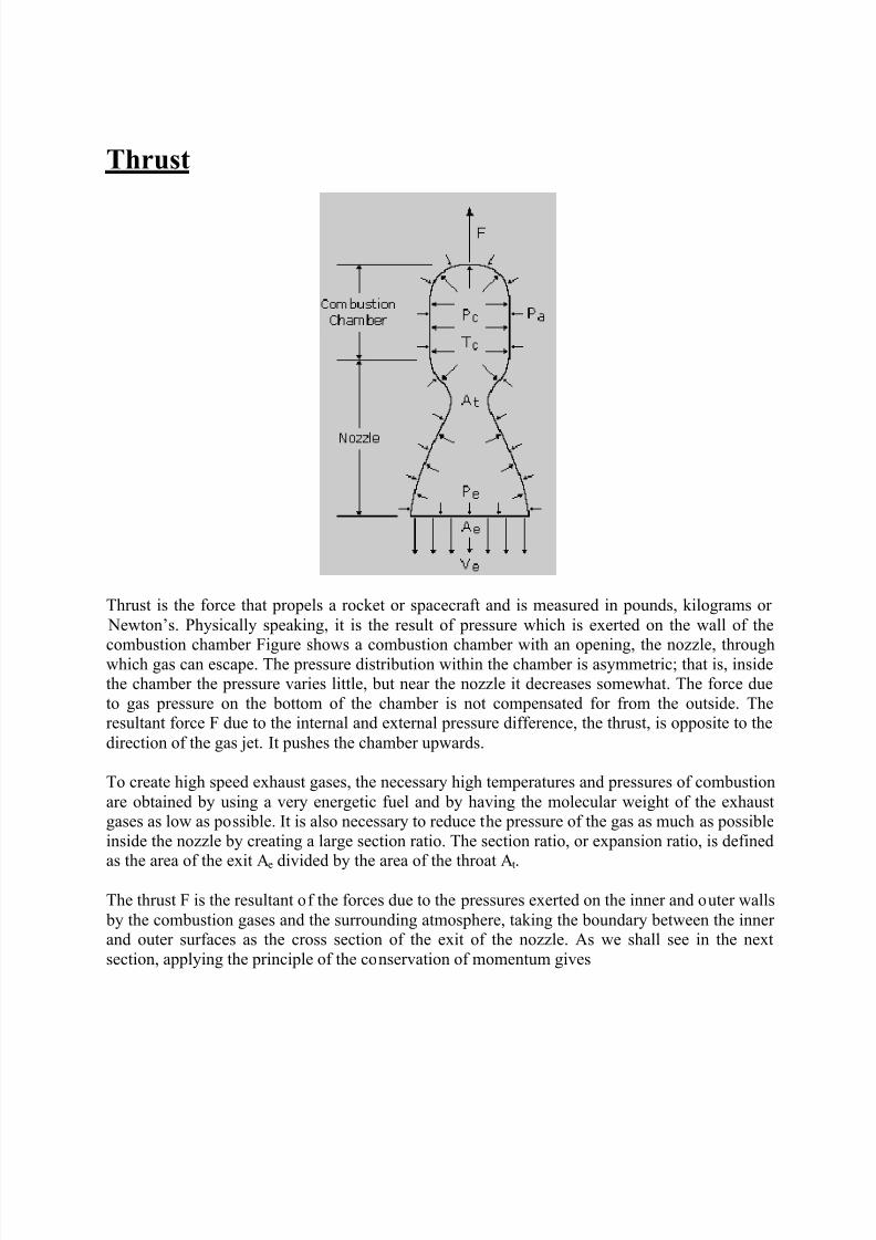
Thrust is the force that propels a rocket or spacecraft and is measured in pounds, kilograms or
Newton¶s. Physically speaking, it is the result of pressure which is exerted on the wall of the
combustion chamber Figure shows a combustion chamber with an opening, the nozzle, throughwhich gas can escape. The pressure distribution within the chamber is asymmetric; that is, insidethe chamber the pressure varies little, but near the nozzle it decreases somewhat. The force due
to gas pressure on the bottom of the chamber is not compensated for from the outside. Theresultant force F due to the internal and external pressure difference, the thrust, is opposite to the
direction of the gas jet. It pushes the chamber upwards.
To create high speed exhaust gases, the necessary high temperatures and pressures of combustion
are obtained by using a very energetic fuel and by having the molecular weight of the exhaustgases as low as possible. It is also necessary to reduce the pressure of the gas as much as possible
inside the nozzle by creating a large section ratio. The section ratio, or expansion ratio, is defined
as the area of the exit Ae divided by the area of the throat At.
The thrust F is the resultant of the forces due to the pressures exerted on the inner and outer walls
by the combustion gases and the surrounding atmosphere, taking the boundary between the inner and outer surfaces as the cross section of the exit of the nozzle. As we shall see in the next
section, applying the principle of the conservation of momentum gives
8/8/2019 Rocket Propulsion in Brief
http://slidepdf.com/reader/full/rocket-propulsion-in-brief 6/24
where q is the rate of the ejected mass flow, Pa the pressure of the ambient atmosphere, Pe the pressure of the exhaust gases and Ve their ejection speed. Thrust is specified either at sea level or
in a vacuum.
Conservation of Momentum
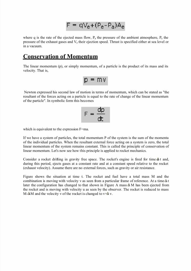
The linear momentum (p), or simply momentum, of a particle is the product of its mass and itsvelocity. That is,
Newton expressed his second law of motion in terms of momentum, which can be stated as "the
resultant of the forces acting on a particle is equal to the rate of change of the linear momentumof the particle". In symbolic form this becomes
which is equivalent to the expression F=ma.
If we have a system of particles, the total momentum P of the system is the sum of the momenta
of the individual particles. When the resultant external force acting on a system is zero, the totallinear momentum of the system remains constant. This is called the principle of conservation of
linear momentum. Let's now see how this principle is applied to rocket mechanics.
Consider a rocket drifting in gravity free space. The rocket's engine is fired for time t and,
during this period, ejects gases at a constant rate and at a constant speed relative to the rocket(exhaust velocity). Assume there are no external forces, such as gravity or air resistance.
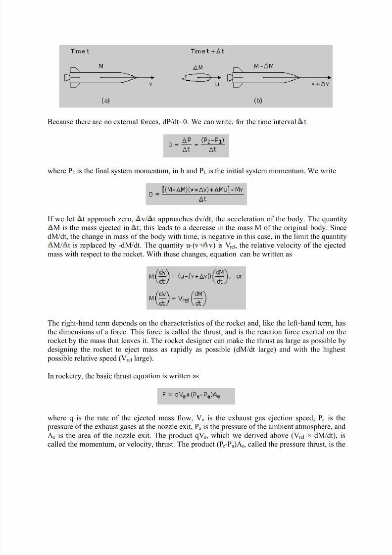
Figure shows the situation at time t. The rocket and fuel have a total mass M and the
combination is moving with velocity v as seen from a particular frame of reference. At a time tlater the configuration has changed to that shown in Figure A mass M has been ejected from
the rocket and is moving with velocity u as seen by the observer. The rocket is reduced to massM- M and the velocity v of the rocket is changed to v+ v.
8/8/2019 Rocket Propulsion in Brief
http://slidepdf.com/reader/full/rocket-propulsion-in-brief 7/24
Because there are no external forces, dP/dt=0. We can write, for the time interval t
where P2 is the final system momentum, in b and P1 is the initial system momentum, We write
If we let t approach zero, v/ t approaches dv/dt, the acceleration of the body. The quantityM is the mass ejected in t; this leads to a decrease in the mass M of the original body. Since
dM/dt, the change in mass of the body with time, is negative in this case, in the limit the quantityM/ t is replaced by -dM/dt. The quantity u-(v+ v) is Vrel, the relative velocity of the ejected
mass with respect to the rocket. With these changes, equation can be written as
The right-hand term depends on the characteristics of the rocket and, like the left-hand term, hasthe dimensions of a force. This force is called the thrust, and is the reaction force exerted on the
rocket by the mass that leaves it. The rocket designer can make the thrust as large as possible bydesigning the rocket to eject mass as rapidly as possible (dM/dt large) and with the highest
possible relative speed (Vrel large).
In rocketry, the basic thrust equation is written as
where q is the rate of the ejected mass flow, Ve is the exhaust gas ejection speed, Pe is the pressure of the exhaust gases at the nozzle exit, Pa is the pressure of the ambient atmosphere, and
Ae is the area of the nozzle exit. The product qVe, which we derived above (Vrel × dM/dt), iscalled the momentum, or velocity, thrust. The product (Pe-Pa)Ae, called the pressure thrust, is the
8/8/2019 Rocket Propulsion in Brief
http://slidepdf.com/reader/full/rocket-propulsion-in-brief 8/24
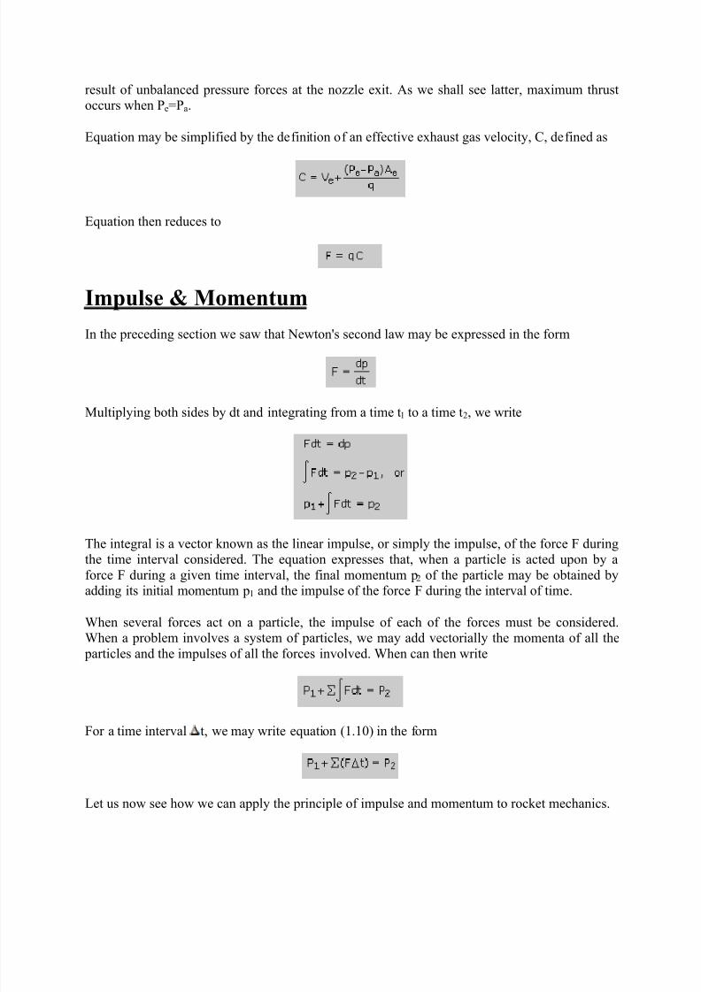
result of unbalanced pressure forces at the nozzle exit. As we shall see latter, maximum thrustoccurs when Pe=Pa.
Equation may be simplified by the definition of an effective exhaust gas velocity, C, defined as
Equation then reduces to
Impulse & Momentum
In the preceding section we saw that Newton's second law may be expressed in the form
Multiplying both sides by dt and integrating from a time t1 to a time t2, we write
The integral is a vector known as the linear impulse, or simply the impulse, of the force F duringthe time interval considered. The equation expresses that, when a particle is acted upon by a
force F during a given time interval, the final momentum p2 of the particle may be obtained byadding its initial momentum p1 and the impulse of the force F during the interval of time.
When several forces act on a particle, the impulse of each of the forces must be considered.When a problem involves a system of particles, we may add vectorially the momenta of all the
particles and the impulses of all the forces involved. When can then write
For a time interval t, we may write equation (1.10) in the form
Let us now see how we can apply the principle of impulse and momentum to rocket mechanics.
8/8/2019 Rocket Propulsion in Brief
http://slidepdf.com/reader/full/rocket-propulsion-in-brief 9/24
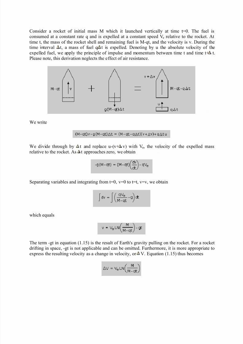
Consider a rocket of initial mass M which it launched vertically at time t=0. The fuel isconsumed at a constant rate q and is expelled at a constant speed Ve relative to the rocket. At
time t, the mass of the rocket shell and remaining fuel is M-qt, and the velocity is v. During thetime interval t, a mass of fuel q t is expelled. Denoting by u the absolute velocity of the
expelled fuel, we apply the principle of impulse and momentum between time t and time t+ t.
Please note, this derivation neglects the effect of air resistance.
We write
We divide through by t and replace u-(v+ v) with Ve, the velocity of the expelled mass
relative to the rocket. As t approaches zero, we obtain
Separating variables and integrating from t=0, v=0 to t=t, v=v, we obtain
which equals
The term -gt in equation (1.15) is the result of Earth's gravity pulling on the rocket. For a rocketdrifting in space, -gt is not applicable and can be omitted. Furthermore, it is more appropriate to
express the resulting velocity as a change in velocity, or V. Equation (1.15) thus becomes
8/8/2019 Rocket Propulsion in Brief
http://slidepdf.com/reader/full/rocket-propulsion-in-brief 10/24
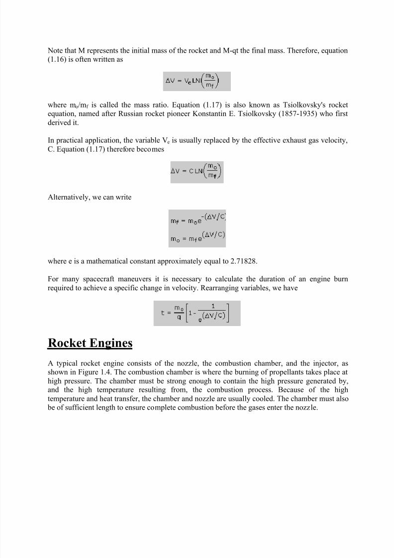
Note that M represents the initial mass of the rocket and M-qt the final mass. Therefore, equation(1.16) is often written as
where mo/mf is called the mass ratio. Equation (1.17) is also known as Tsiolkovsky's rocketequation, named after Russian rocket pioneer Konstantin E. Tsiolkovsky (1857-1935) who first
derived it.
In practical application, the variable Ve is usually replaced by the effective exhaust gas velocity,
C. Equation (1.17) therefore becomes
Alternatively, we can write
where e is a mathematical constant approximately equal to 2.71828.
For many spacecraft maneuvers it is necessary to calculate the duration of an engine burn
required to achieve a specific change in velocity. Rearranging variables, we have
Rocket Engines
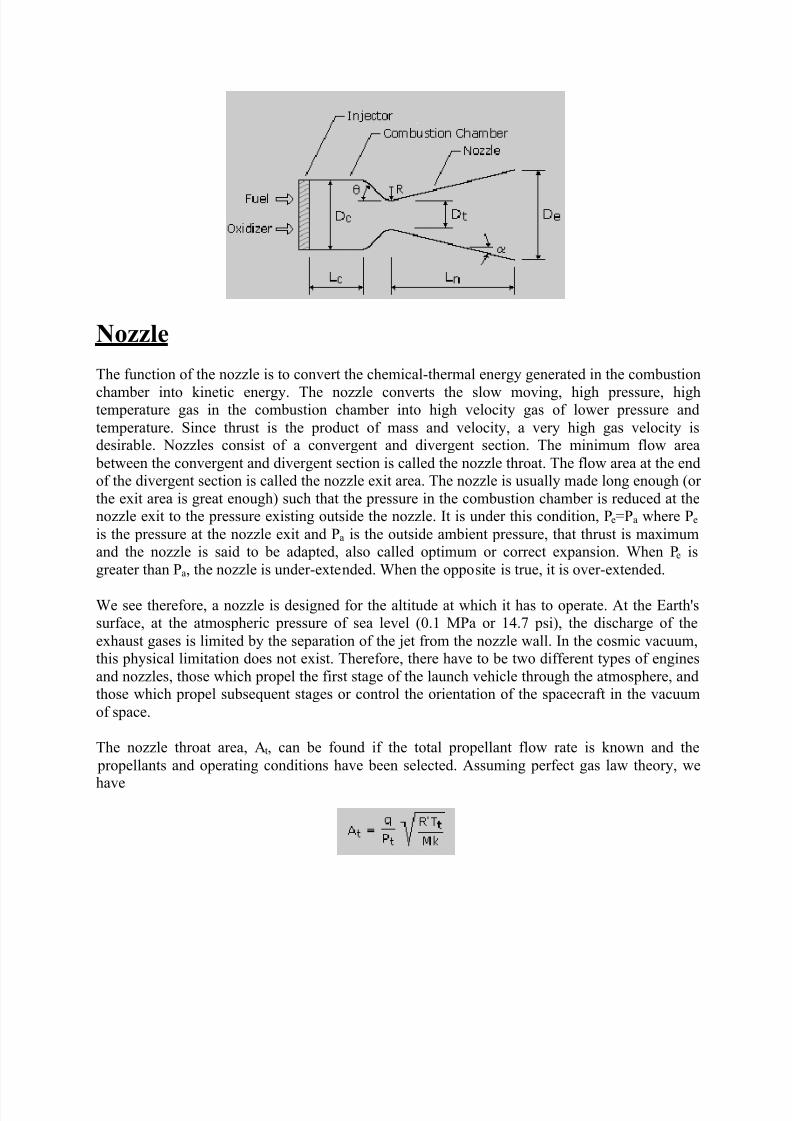
A typical rocket engine consists of the nozzle, the combustion chamber, and the injector, asshown in Figure 1.4. The combustion chamber is where the burning of propellants takes place at
high pressure. The chamber must be strong enough to contain the high pressure generated by,
and the high temperature resulting from, the combustion process. Because of the hightemperature and heat transfer, the chamber and nozzle are usually cooled. The chamber must also be of sufficient length to ensure complete combustion before the gases enter the nozzle.
8/8/2019 Rocket Propulsion in Brief
http://slidepdf.com/reader/full/rocket-propulsion-in-brief 11/24
Nozzle
The function of the nozzle is to convert the chemical-thermal energy generated in the combustion
chamber into kinetic energy. The nozzle converts the slow moving, high pressure, hightemperature gas in the combustion chamber into high velocity gas of lower pressure and
temperature. Since thrust is the product of mass and velocity, a very high gas velocity isdesirable. Nozzles consist of a convergent and divergent section. The minimum flow area
between the convergent and divergent section is called the nozzle throat. The flow area at the endof the divergent section is called the nozzle exit area. The nozzle is usually made long enough (or
the exit area is great enough) such that the pressure in the combustion chamber is reduced at thenozzle exit to the pressure existing outside the nozzle. It is under this condition, Pe=Pa where Pe
is the pressure at the nozzle exit and Pa is the outside ambient pressure, that thrust is maximumand the nozzle is said to be adapted, also called optimum or correct expansion. When Pe is
greater than Pa, the nozzle is under-extended. When the opposite is true, it is over-extended.
We see therefore, a nozzle is designed for the altitude at which it has to operate. At the Earth'ssurface, at the atmospheric pressure of sea level (0.1 MPa or 14.7 psi), the discharge of the
exhaust gases is limited by the separation of the jet from the nozzle wall. In the cosmic vacuum,this physical limitation does not exist. Therefore, there have to be two different types of engines
and nozzles, those which propel the first stage of the launch vehicle through the atmosphere, andthose which propel subsequent stages or control the orientation of the spacecraft in the vacuum
of space.
The nozzle throat area, At, can be found if the total propellant flow rate is known and the
propellants and operating conditions have been selected. Assuming perfect gas law theory, we
have
8/8/2019 Rocket Propulsion in Brief
http://slidepdf.com/reader/full/rocket-propulsion-in-brief 12/24
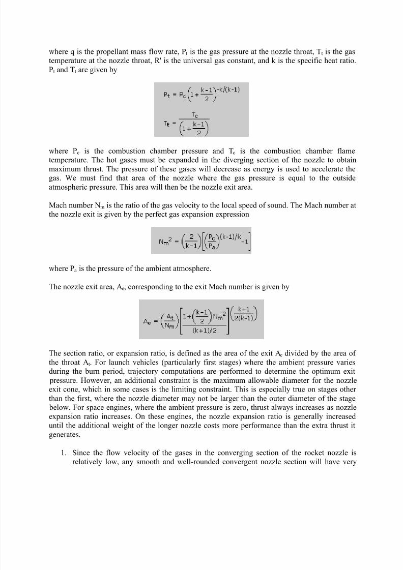
where q is the propellant mass flow rate, Pt is the gas pressure at the nozzle throat, T t is the gastemperature at the nozzle throat, R' is the universal gas constant, and k is the specific heat ratio.
Pt and Tt are given by
where Pc is the combustion chamber pressure and Tc is the combustion chamber flametemperature. The hot gases must be expanded in the diverging section of the nozzle to obtain
maximum thrust. The pressure of these gases will decrease as energy is used to accelerate thegas. We must find that area of the nozzle where the gas pressure is equal to the outside
atmospheric pressure. This area will then be the nozzle exit area.
Mach number Nm is the ratio of the gas velocity to the local speed of sound. The Mach number atthe nozzle exit is given by the perfect gas expansion expression
where Pa is the pressure of the ambient atmosphere.
The nozzle exit area, Ae, corresponding to the exit Mach number is given by
The section ratio, or expansion ratio, is defined as the area of the exit Ae divided by the area of
the throat At. For launch vehicles (particularly first stages) where the ambient pressure variesduring the burn period, trajectory computations are performed to determine the optimum exit
pressure. However, an additional constraint is the maximum allowable diameter for the nozzleexit cone, which in some cases is the limiting constraint. This is especially true on stages other
than the first, where the nozzle diameter may not be larger than the outer diameter of the stage below. For space engines, where the ambient pressure is zero, thrust always increases as nozzle
expansion ratio increases. On these engines, the nozzle expansion ratio is generally increaseduntil the additional weight of the longer nozzle costs more performance than the extra thrust it
generates.
1. Since the flow velocity of the gases in the converging section of the rocket nozzle isrelatively low, any smooth and well-rounded convergent nozzle section will have very
8/8/2019 Rocket Propulsion in Brief
http://slidepdf.com/reader/full/rocket-propulsion-in-brief 13/24
low energy loses. By contrast, the contour of the diverging nozzle section is veryimportant to performance, because of the very high flow velocities involved. The
selection of an optimum nozzle shape for a given expansion ratio is generally influenced by the following design considerations and goals: (1) uniform, parallel, axial gas flow at
the nozzle exit for maximum momentum vector, (2) minimum separation and turbulence
losses within the nozzle, (3) shortest possible nozzle length for minimum space envelope,weight, wall friction losses, and cooling requirements, and (4) ease of manufacturing.
Conical nozzle:
In early rocket engine applications, the conical nozzle, which proved satisfactory in mostrespects, was used almost exclusively. A conical nozzle allows ease of manufacture and
flexibility in converting an existing design to higher or lower expansion ratio without major redesign.
The configuration of a typical conical nozzle is shown in Figure 1.4. The nozzle throat section
has the contour of a circular arc with radius R, ranging from 0.25 to 0.75 times the throatdiameter, Dt. The half-angle of the nozzle convergent cone section, , can range from 20 to 45degrees. The divergent cone half-angle, , varies from approximately 12 to 18 degrees. The
conical nozzle with a 15-degree divergent half-angle has become almost a standard because it isa good compromise on the basis of weight, length, and performance.
Since certain performance losses occur in a conical nozzle as a result of the nonaxial component
of the exhaust gas velocity, a correction factor, , is applied in the calculation of the exit-gasmomentum. This factor (thrust efficiency) is the ratio between the exit-gas momentum of the
conical nozzle and that of an ideal nozzle with uniform, parallel, axial gas-flow. The value of can be expressed by the following equation:
Bell nozzle:
8/8/2019 Rocket Propulsion in Brief
http://slidepdf.com/reader/full/rocket-propulsion-in-brief 14/24
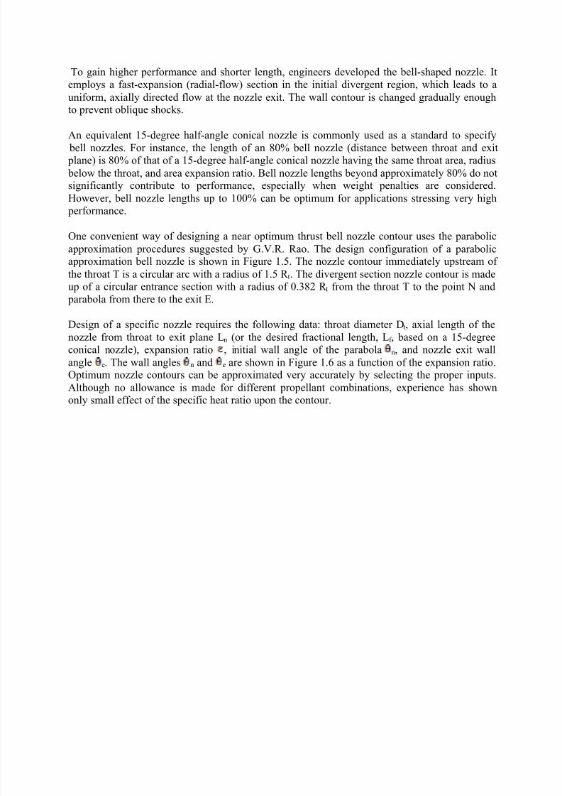
To gain higher performance and shorter length, engineers developed the bell-shaped nozzle. Itemploys a fast-expansion (radial-flow) section in the initial divergent region, which leads to a
uniform, axially directed flow at the nozzle exit. The wall contour is changed gradually enoughto prevent oblique shocks.
An equivalent 15-degree half-angle conical nozzle is commonly used as a standard to specify bell nozzles. For instance, the length of an 80% bell nozzle (distance between throat and exit plane) is 80% of that of a 15-degree half-angle conical nozzle having the same throat area, radius
below the throat, and area expansion ratio. Bell nozzle lengths beyond approximately 80% do notsignificantly contribute to performance, especially when weight penalties are considered.
However, bell nozzle lengths up to 100% can be optimum for applications stressing very high performance.
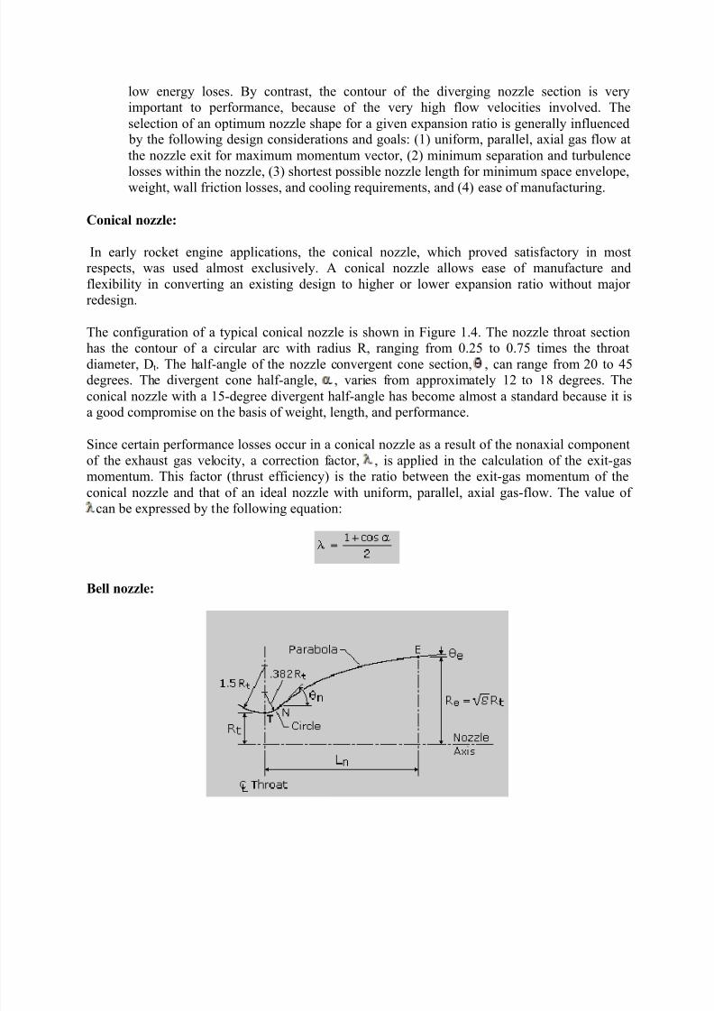
One convenient way of designing a near optimum thrust bell nozzle contour uses the parabolic
approximation procedures suggested by G.V.R. Rao. The design configuration of a parabolicapproximation bell nozzle is shown in Figure 1.5. The nozzle contour immediately upstream of
the throat T is a circular arc with a radius of 1.5 R t. The divergent section nozzle contour is madeup of a circular entrance section with a radius of 0.382 R t from the throat T to the point N and
parabola from there to the exit E.
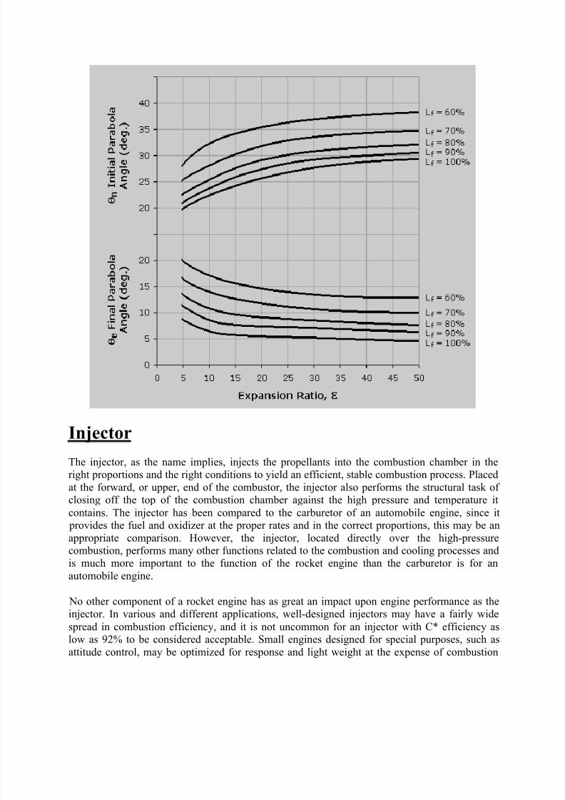
Design of a specific nozzle requires the following data: throat diameter Dt, axial length of the
nozzle from throat to exit plane Ln (or the desired fractional length, Lf , based on a 15-degreeconical nozzle), expansion ratio , initial wall angle of the parabola n, and nozzle exit wall
angle e. The wall angles n and e are shown in Figure 1.6 as a function of the expansion ratio.Optimum nozzle contours can be approximated very accurately by selecting the proper inputs.
Although no allowance is made for different propellant combinations, experience has shownonly small effect of the specific heat ratio upon the contour.
8/8/2019 Rocket Propulsion in Brief
http://slidepdf.com/reader/full/rocket-propulsion-in-brief 15/24
Injector
The injector, as the name implies, injects the propellants into the combustion chamber in theright proportions and the right conditions to yield an efficient, stable combustion process. Placed
at the forward, or upper, end of the combustor, the injector also performs the structural task of closing off the top of the combustion chamber against the high pressure and temperature it
contains. The injector has been compared to the carburetor of an automobile engine, since it provides the fuel and oxidizer at the proper rates and in the correct proportions, this may be an
appropriate comparison. However, the injector, located directly over the high-pressurecombustion, performs many other functions related to the combustion and cooling processes and
is much more important to the function of the rocket engine than the carburetor is for anautomobile engine.
No other component of a rocket engine has as great an impact upon engine performance as theinjector. In various and different applications, well-designed injectors may have a fairly wide
spread in combustion efficiency, and it is not uncommon for an injector with C* efficiency aslow as 92% to be considered acceptable. Small engines designed for special purposes, such as
attitude control, may be optimized for response and light weight at the expense of combustion
8/8/2019 Rocket Propulsion in Brief
http://slidepdf.com/reader/full/rocket-propulsion-in-brief 16/24
efficiency, and may be deemed very satisfactory even if efficiency falls below 90%. In general,however, recently well-designed injection systems have demonstrated C* efficiencies so close to
100% of theoretical that the ability to measure this parameter is the limiting factor in itsdetermination. High levels of combustion efficiency derive from uniform distribution of the
desired mixture ratio and fine atomization of the liquid propellants. Local mixing within the
injection-element spray pattern must take place at virtually a microscopic level to ensurecombustion efficiencies approaching 100%.
Combustion stability is also a very important requirement for a satisfactory injector design.Under certain conditions, shock and detonation waves are generated by local disturbances in the
chamber, possibly caused by fluctuations in mixing or propellant flow. These may trigger pressure oscillations that are amplified and maintained by the combustion processes. Such high-
amplitude waves - referred to as combustion instability - produce high levels of vibration andheat flux that can be very destructive. A major portion of the design and development effort
therefore concerns stable combustion. High performance can become secondary if the injector iseasily triggered into destructive instability, and many of the injector parameters that provide high
performance appear to reduce the stability margin.
Power Cycles
Liquid bipropellant rocket engines can be categorized according to their power cycles, that is,how power is derived to feed propellants to the main combustion chamber. Described below are
some of the more common types.
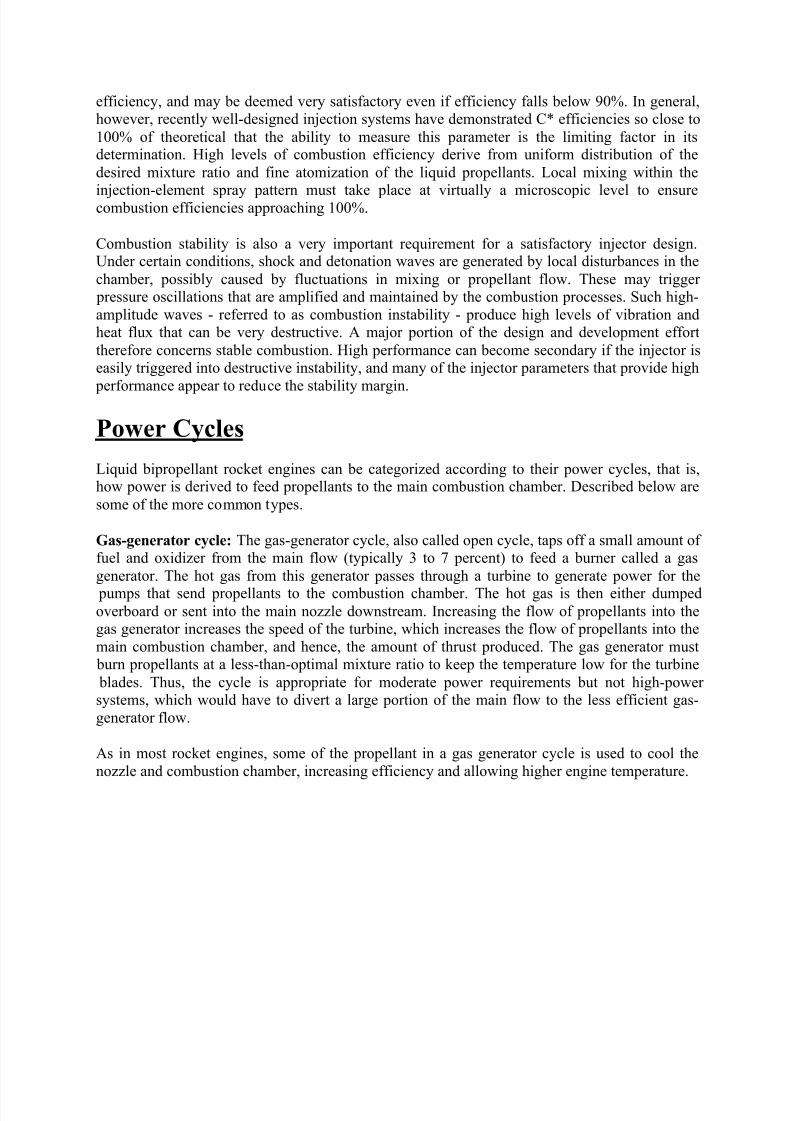
Gas-generator cycle: The gas-generator cycle, also called open cycle, taps off a small amount of fuel and oxidizer from the main flow (typically 3 to 7 percent) to feed a burner called a gas
generator. The hot gas from this generator passes through a turbine to generate power for the
pumps that send propellants to the combustion chamber. The hot gas is then either dumpedoverboard or sent into the main nozzle downstream. Increasing the flow of propellants into thegas generator increases the speed of the turbine, which increases the flow of propellants into the
main combustion chamber, and hence, the amount of thrust produced. The gas generator must burn propellants at a less-than-optimal mixture ratio to keep the temperature low for the turbine
blades. Thus, the cycle is appropriate for moderate power requirements but not high-power systems, which would have to divert a large portion of the main flow to the less efficient gas-
generator flow.
As in most rocket engines, some of the propellant in a gas generator cycle is used to cool the
nozzle and combustion chamber, increasing efficiency and allowing higher engine temperature.
8/8/2019 Rocket Propulsion in Brief
http://slidepdf.com/reader/full/rocket-propulsion-in-brief 17/24
Staged combustion cycle: In a staged combustion cycle, also called closed cycle, the propellantsare burned in stages. Like the gas-generator cycle, this cycle also has a burner, called a
preburner, to generate gas for a turbine. The preburner taps off and burns a small amount of one propellant and a large amount of the other, producing an oxidizer-rich or fuel-rich hot gas
mixture that is mostly unburned vaporized propellant. This hot gas is then passed through theturbine, injected into the main chamber, and burned again with the remaining propellants. The
advantage over the gas-generator cycle is that all of the propellants are burned at the optimalmixture ratio in the main chamber and no flow is dumped overboard. The staged combustion
cycle is often used for high-power applications. The higher the chamber pressure, the smaller andlighter the engine can be to produce the same thrust. Development cost for this cycle is higher
because the high pressures complicate the development process. Further disadvantages are harshturbine conditions, high temperature piping required to carry hot gases, and a very complicated
feedback and control design.
Staged combustion was invented by Soviet engineers and first appeared in 1960. In the West, thefirst laboratory staged combustion test engine was built in Germany in 1963.
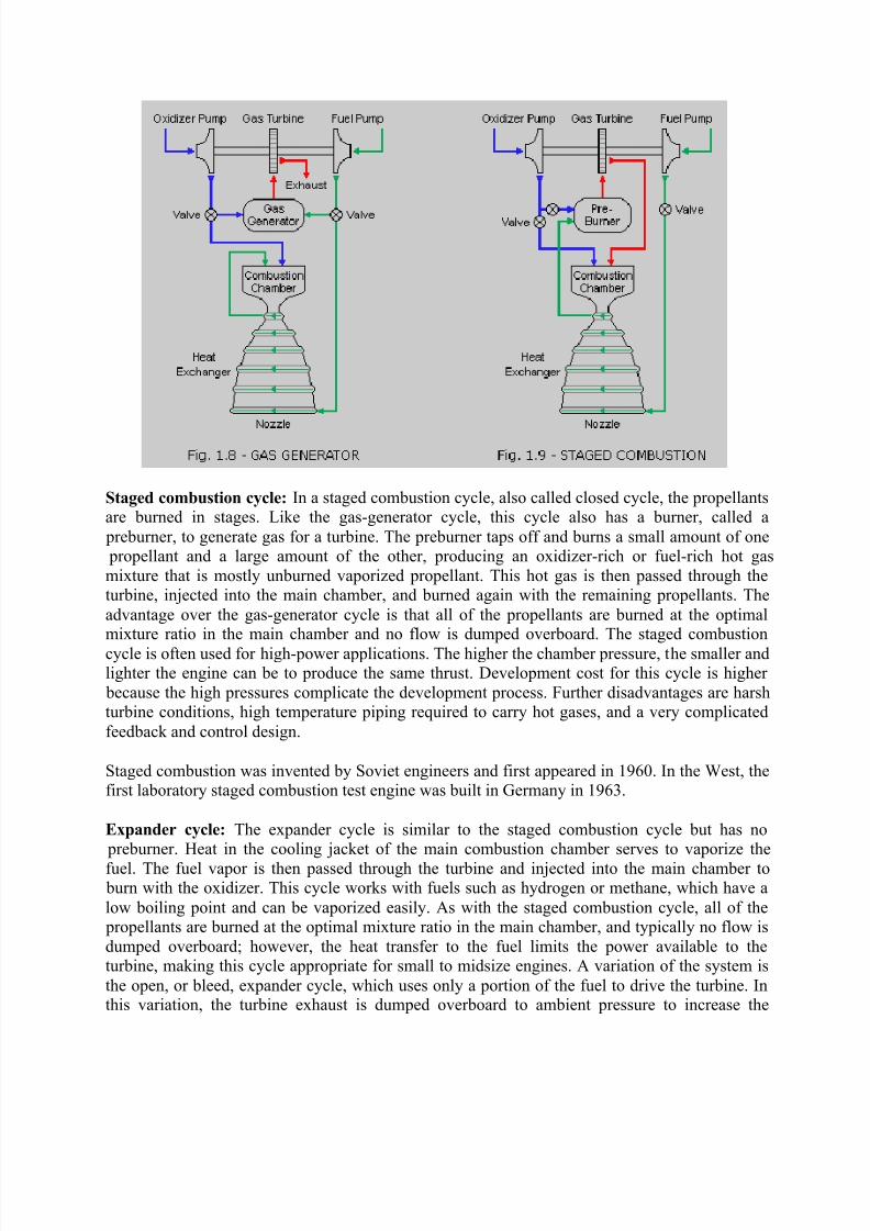
Expander cycle: The expander cycle is similar to the staged combustion cycle but has no preburner. Heat in the cooling jacket of the main combustion chamber serves to vaporize the
fuel. The fuel vapor is then passed through the turbine and injected into the main chamber to burn with the oxidizer. This cycle works with fuels such as hydrogen or methane, which have a
low boiling point and can be vaporized easily. As with the staged combustion cycle, all of the propellants are burned at the optimal mixture ratio in the main chamber, and typically no flow is
dumped overboard; however, the heat transfer to the fuel limits the power available to theturbine, making this cycle appropriate for small to midsize engines. A variation of the system is
the open, or bleed, expander cycle, which uses only a portion of the fuel to drive the turbine. Inthis variation, the turbine exhaust is dumped overboard to ambient pressure to increase the
8/8/2019 Rocket Propulsion in Brief
http://slidepdf.com/reader/full/rocket-propulsion-in-brief 18/24
turbine pressure ratio and power output. This can achieve higher chamber pressures than theclosed expander cycle although at lower efficiency because of the overboard flow.
Pressure-fed cycle: The simplest system, the pressure-fed cycle, does not have pumps or
turbines but instead relies on tank pressure to feed the propellants into the main chamber. In practice, the cycle is limited to relatively low chamber pressures because higher pressures make
the vehicle tanks too heavy. The cycle can be reliable, given its reduced part count and
complexity compared with other systems.
Engine Cooling
The heat created during combustion in a rocket engine is contained within the exhaust gases.
Most of this heat is expelled along with the gas that contains it; however, heat is transferred tothe thrust chamber walls in quantities sufficient to require attention.
Thrust chamber designs are generally categorized or identified by the hot gas wall cooling
method or the configuration of the coolant passages, where the coolant pressure inside may be ashigh as 500 atmospheres. The high combustion temperatures (2,500 to 3,600
oK) and the high
heat transfer rates (up to 16 kJ/cm2-s) encountered in a combustion chamber present a formidablechallenge to the designer. To meet this challenge, several chamber cooling techniques have been
utilized successfully. Selection of the optimum cooling method for a thrust chamber depends onmany considerations, such as type of propellant, chamber pressure, available coolant pressure,combustion chamber configuration, and combustion chamber material.
8/8/2019 Rocket Propulsion in Brief
http://slidepdf.com/reader/full/rocket-propulsion-in-brief 19/24
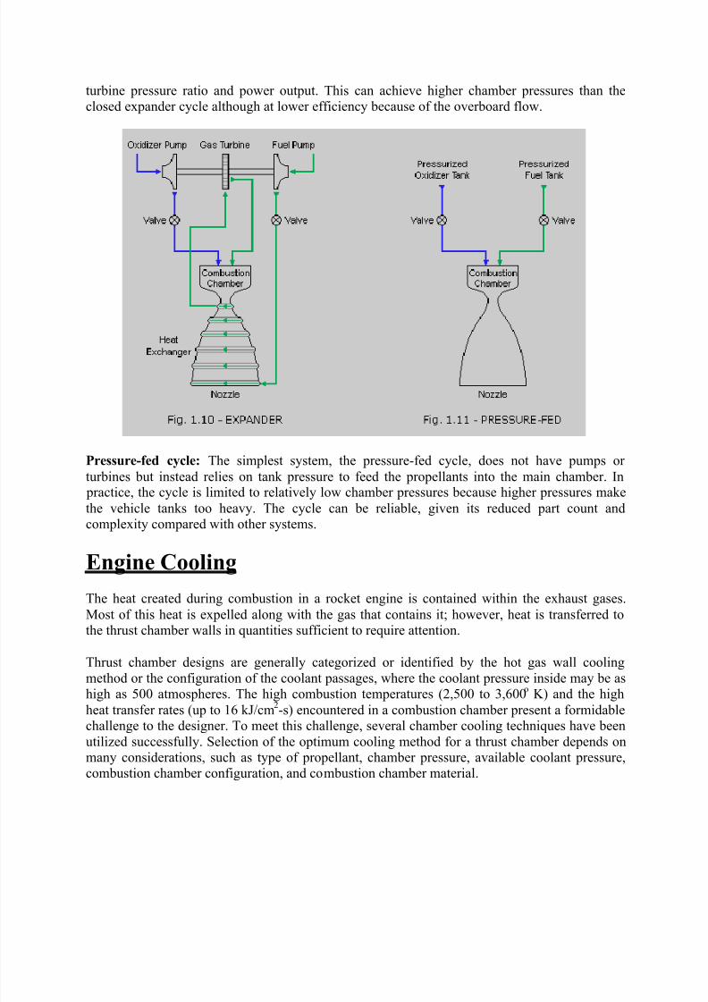
Regenerative cooling is the most widely used method of cooling a thrust chamber and is
accomplished by flowing high-velocity coolant over the back side of the chamber hot gas wall toconvectively cool the hot gas liner. The coolant with the heat input from cooling the liner is then
discharged into the injector and utilized as a propellant.
Earlier thrust chamber designs, such as the V-2 and Redstone, had low chamber pressure, lowheat flux and low coolant pressure requirements, which could be satisfied by a simplified
"double wall chamber" design with regenerative and film cooling. For subsequent rocket engine
applications, however, chamber pressures were increased and the cooling requirements becamemore difficult to satisfy. It became necessary to design new coolant configurations that weremore efficient structurally and had improved heat transfer characteristics.
This led to the design of "tubular wall" thrust chambers, by far the most widely used designapproach for the vast majority of large rocket engine applications. These chamber designs have
been successfully used for the Thor, Jupiter, Atlas, H-1, J-2, F-1, RS-27 and several other Air Force and NASA rocket engine applications. The primary advantage of the design is its light
weight and the large experience base that has accrued. But as chamber pressures and hot gas wallheat fluxes have continued to increase (>100 atm), still more effective methods have been
needed.
One solution has been "channel wall" thrust chambers, so named because the hot gas wallcooling is accomplished by flowing coolant through rectangular channels, which are machined or
formed into a hot gas liner fabricated from a high-conductivity material, such as copper or acopper alloy. A prime example of a channel wall combustion chamber is the SSME, which
operates at 204 atmospheres nominal chamber pressure at 3,600 K for a duration of 520 seconds.Heat transfer and structural characteristics are excellent.
8/8/2019 Rocket Propulsion in Brief
http://slidepdf.com/reader/full/rocket-propulsion-in-brief 20/24
In addition to the regenerative cooled designs mentioned above, other thrust chamber designshave been fabricated for rocket engines using dump cooling, film cooling, transpiration cooling,
ablative liners and radiation cooling. Although regenerative cooled combustion chambers have proven to be the best approach for cooling large liquid rocket engines, other methods of cooling
have also been successfully used for cooling thrust chamber assemblies. Examples include:
Dump cooling which is similar to regenerative cooling because the coolant flows through small passages over the back side of the thrust chamber wall. The difference, however, is that after
cooling the thrust chamber, the coolant is discharged overboard through openings at the aft endof the divergent nozzle. This method has limited application because of the performance loss
resulting from dumping the coolant overboard. To date, dump cooling has not been used in anactual application.
Film cooling provides protection from excessive heat by introducing a thin film of coolant or
propellant through orifices around the injector periphery or through manifolded orifices in thechamber wall near the injector or chamber throat region. This method is typically used in high
heat flux regions and in combination with regenerative cooling.
Transpiration cooling provides coolant (either gaseous or liquid propellant) through a porous
chamber wall at a rate sufficient to maintain the chamber hot gas wall to the desired temperature.The technique is really a special case of film cooling.
With ablative cooling, combustion gas-side wall material is sacrificed by melting, vaporization
and chemical changes to dissipate heat. As a result, relatively cool gases flow over the wallsurface, thus lowering the boundary-layer temperature and assisting the cooling process.
With radiation cooling, heat is radiated from the outer surface of the combustion chamber or
nozzle extension wall. Radiation cooling is typically used for small thrust chambers with a high-temperature wall material (refractory) and in low-heat flux regions, such as a nozzle extension.
Solid Rocket Motors
Solid rockets motors store propellants in solid form. The fuel is typically powdered aluminum
and the oxidizer is ammonium perchlorate. A synthetic rubber binder such as polybutadieneholds the fuel and oxidizer powders together. Though lower performing than liquid propellant
rockets, the operational simplicity of a solid rocket motor often makes it the propulsion system of choice.
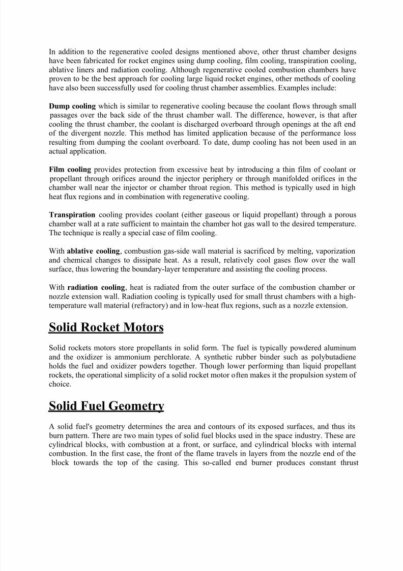
Solid Fuel Geometry
A solid fuel's geometry determines the area and contours of its exposed surfaces, and thus its
burn pattern. There are two main types of solid fuel blocks used in the space industry. These arecylindrical blocks, with combustion at a front, or surface, and cylindrical blocks with internalcombustion. In the first case, the front of the flame travels in layers from the nozzle end of the
block towards the top of the casing. This so-called end burner produces constant thrust
8/8/2019 Rocket Propulsion in Brief
http://slidepdf.com/reader/full/rocket-propulsion-in-brief 21/24
throughout the burn. In the second, more usual case, the combustion surface develops along thelength of a central channel. Sometimes the channel has a star shaped, or other, geometry to
moderate the growth of this surface.
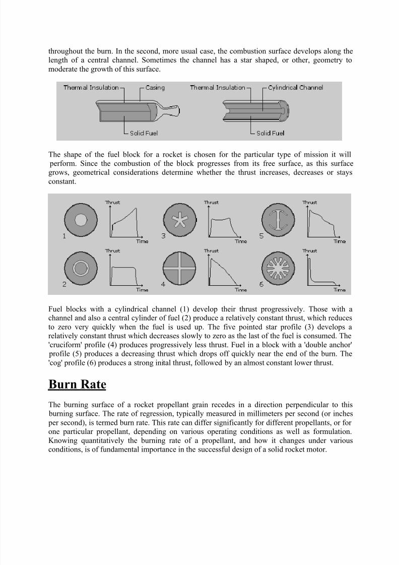
The shape of the fuel block for a rocket is chosen for the particular type of mission it will
perform. Since the combustion of the block progresses from its free surface, as this surfacegrows, geometrical considerations determine whether the thrust increases, decreases or stays
constant.
Fuel blocks with a cylindrical channel (1) develop their thrust progressively. Those with achannel and also a central cylinder of fuel (2) produce a relatively constant thrust, which reduces
to zero very quickly when the fuel is used up. The five pointed star profile (3) develops arelatively constant thrust which decreases slowly to zero as the last of the fuel is consumed. The
'cruciform' profile (4) produces progressively less thrust. Fuel in a block with a 'double anchor' profile (5) produces a decreasing thrust which drops off quickly near the end of the burn. The
'cog' profile (6) produces a strong inital thrust, followed by an almost constant lower thrust.
Burn Rate
The burning surface of a rocket propellant grain recedes in a direction perpendicular to this burning surface. The rate of regression, typically measured in millimeters per second (or inches
per second), is termed burn rate. This rate can differ significantly for different propellants, or for one particular propellant, depending on various operating conditions as well as formulation.
Knowing quantitatively the burning rate of a propellant, and how it changes under variousconditions, is of fundamental importance in the successful design of a solid rocket motor.
8/8/2019 Rocket Propulsion in Brief
http://slidepdf.com/reader/full/rocket-propulsion-in-brief 22/24
Propellant burning rate is influenced by certain factors, the most significant being: combustionchamber pressure, initial temperature of the propellant grain, velocity of the combustion gases
flowing parallel to the burning surface, local static pressure, and motor acceleration and spin.These factors are discussed below.
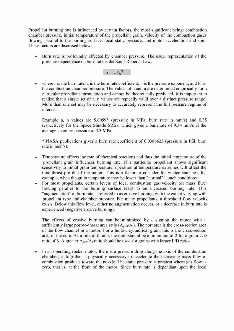
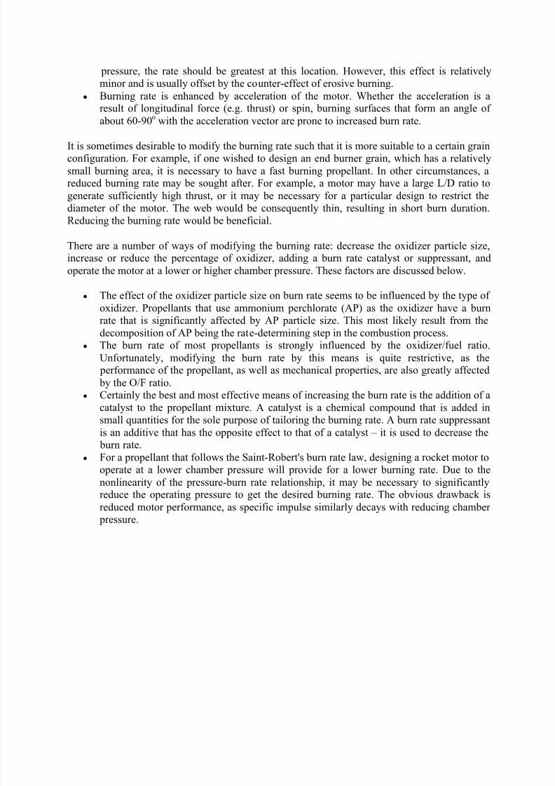
y Burn rate is profoundly affected by chamber pressure. The usual representation of the pressure dependence on burn rate is the Saint-Robert's Law,
y where r is the burn rate, a is the burn rate coefficient, n is the pressure exponent, and P c isthe combustion chamber pressure. The values of a and n are determined empirically for a
particular propellant formulation and cannot be theoretically predicted. It is important torealize that a single set of a, n values are typically valid over a distinct pressure range.
More than one set may be necessary to accurately represent the full pressure regime of interest.
Example a, n values are 5.6059* (pressure in MPa, burn rate in mm/s) and 0.35respectively for the Space Shuttle SRBs, which gives a burn rate of 9.34 mm/s at the
average chamber pressure of 4.3 MPa.
* NASA publications gives a burn rate coefficient of 0.0386625 (pressure in PSI, burnrate in inch/s).
y Temperature affects the rate of chemical reactions and thus the initial temperature of the
propellant grain influences burning rate. If a particular propellant shows significantsensitivity to initial grain temperature, operation at temperature extremes will affect the
time-thrust profile of the motor. This is a factor to consider for winter launches, for example, when the grain temperature may be lower than "normal" launch conditions.
y For most propellants, certain levels of local combustion gas velocity (or mass flux)flowing parallel to the burning surface leads to an increased burning rate. This
"augmentation" of burn rate is referred to as erosive burning, with the extent varying with propellant type and chamber pressure. For many propellants, a threshold flow velocityexists. Below this flow level, either no augmentation occurs, or a decrease in burn rate is
experienced (negative erosive burning).
The effects of erosive burning can be minimized by designing the motor with asufficiently large port-to-throat area ratio (A port/At). The port area is the cross-section area
of the flow channel in a motor. For a hollow-cylindrical grain, this is the cross-sectionarea of the core. As a rule of thumb, the ratio should be a minimum of 2 for a grain L/D
ratio of 6. A greater A port/At ratio should be used for grains with larger L/D ratios.
y In an operating rocket motor, there is a pressure drop along the axis of the combustionchamber, a drop that is physically necessary to accelerate the increasing mass flow of
combustion products toward the nozzle. The static pressure is greatest where gas flow iszero, that is, at the front of the motor. Since burn rate is dependant upon the local
8/8/2019 Rocket Propulsion in Brief
http://slidepdf.com/reader/full/rocket-propulsion-in-brief 23/24
pressure, the rate should be greatest at this location. However, this effect is relativelyminor and is usually offset by the counter-effect of erosive burning.
y Burning rate is enhanced by acceleration of the motor. Whether the acceleration is aresult of longitudinal force (e.g. thrust) or spin, burning surfaces that form an angle of
about 60-90o
with the acceleration vector are prone to increased burn rate.
It is sometimes desirable to modify the burning rate such that it is more suitable to a certain grainconfiguration. For example, if one wished to design an end burner grain, which has a relatively
small burning area, it is necessary to have a fast burning propellant. In other circumstances, areduced burning rate may be sought after. For example, a motor may have a large L/D ratio to
generate sufficiently high thrust, or it may be necessary for a particular design to restrict thediameter of the motor. The web would be consequently thin, resulting in short burn duration.
Reducing the burning rate would be beneficial.
There are a number of ways of modifying the burning rate: decrease the oxidizer particle size,increase or reduce the percentage of oxidizer, adding a burn rate catalyst or suppressant, and
operate the motor at a lower or higher chamber pressure. These factors are discussed below.
y The effect of the oxidizer particle size on burn rate seems to be influenced by the type of
oxidizer. Propellants that use ammonium perchlorate (AP) as the oxidizer have a burnrate that is significantly affected by AP particle size. This most likely result from the
decomposition of AP being the rate-determining step in the combustion process.y The burn rate of most propellants is strongly influenced by the oxidizer/fuel ratio.
Unfortunately, modifying the burn rate by this means is quite restrictive, as the performance of the propellant, as well as mechanical properties, are also greatly affected
by the O/F ratio.y Certainly the best and most effective means of increasing the burn rate is the addition of a
catalyst to the propellant mixture. A catalyst is a chemical compound that is added insmall quantities for the sole purpose of tailoring the burning rate. A burn rate suppressant
is an additive that has the opposite effect to that of a catalyst ± it is used to decrease the burn rate.
y For a propellant that follows the Saint-Robert's burn rate law, designing a rocket motor tooperate at a lower chamber pressure will provide for a lower burning rate. Due to the
nonlinearity of the pressure-burn rate relationship, it may be necessary to significantlyreduce the operating pressure to get the desired burning rate. The obvious drawback is
reduced motor performance, as specific impulse similarly decays with reducing chamber pressure.

8/8/2019 Rocket Propulsion in Brief
http://slidepdf.com/reader/full/rocket-propulsion-in-brief 24/24
Reference
Book of Space Transport and Engineering Methods by P Thaxte
en.wiki book s.org/wiki/ Rocket _Propulsion
www.how stuff work s.com/ rocket .ht m