Embed Size (px)
Citation preview

Oregon Institute of Technology Rocket Project Proposal
30 Nov. 2017
Table of Contents
Basic Information 3 Summary 3 Contacts 3
Safety and Legal 4 Overview of Safety Approach 4 Member Safety 5 Design Safety 7 Testing Safety 8 Flight Safety 9
Mission Definition 10 Project Goal 10 Competition Rules Summary 10 Competition Rules Details 10 Senior Project Requirements 11
Liquid-Fueled Engine 12 Overview 12 Engine 12 Propellants 16 Design and Simulation 17 Manufacturing 19 Part Testing 19
Engine Testing Facility 20 Overview 20 Test trailer 20
Test stand 21 Propellant Feed System 22 Fire suppression 23
Supporting Systems 23 Control center 23 Propellant Storage 23
Testing Plan 24
1

Flight Rocket 25 Overview 25 Support Structure 25 Airframe 27 Aivionics 29 Recovery 31 Manufacture and Testing 32
Project Plan 33 Project Schedule 33 Contingency Plans 34 Budget 37
Appendices 41 Appendix A: Propellant Comparison 41 Appendix B: Reference Documents 44
2

1. Basic Information
1.1. Summary This document proposes the Oregon Tech Rocketry Project (OTRP) as a project of the Oregon Tech Rocketry and Aerospace club (OTRA). OTRA is used to refer to the members or facilitators. OTRP refers to the project itself. The objective of the project is to design and build a liquid-fueled rocket to compete in the Experimental Sounding Rocket Association (ESRA) Spaceport America Cup. This project is a suitable senior design projects for engineering, physics, chemistry, and business oriented majors. This project is expected to take at a minimum two years to bring to completion. The focus of this proposal is on the regulatory environment and design goals for the present academic year 2017-2018.
1.2. Contacts Faculty Advisor: Sean Sloan
Associate Professor, OregonTech MMET Department [email protected]
Senior Project Advisor: Dongbin Lee Assistant Professor, OregonTech MMET Department [email protected]
Project Leadership:
David Minar Engine Development Lead [email protected]
Julien Mindlin-Davidson Engine Development Lead [email protected]
Ben Porter Test Stand Development Lead [email protected]
Micah Hicks Flight Rocket Development Lead [email protected]
Brandon Camp Safety Officer and Manufacturing Lead [email protected]
Website: http://otra.space
3
2. Safety and Legal
2.1. Overview of Safety Approach Safety is paramount for any rocketry project and OTRA members are committed to minimizing liability and risk exposure. Rocketry as an amateur and professional pursuit has existed for over 80 years, so comprehensive and verified safety procedures exist. OTRA will follow these procedures to ensure the safety of all participants and property and protect Oregon Tech from liability.
Legal regulations for rocketry are established by the Federal Aviation Association (FAA) and nonbinding but widely referenced regulations are established by the National Fire Protection Association (NFPA). Standards can be found in FAA CFR, Title 14, Chapter 1, Subchapter, Part 101, Subpart C - Amateur Rocketry - included in Appendix B - and NFPA 1127. NFPA 1127 is proprietary and so cannot be reproduced in full, but relevant sections will be summarized below.
Other relevant legal guidelines related to our material handling and manufacturing processes are provided by the EPA and OSHA. OTRA is working closely with the EHS office at Oregon Tech to ensure we meet all regulatory requirements.
Additional guidelines are provided by Tripoli Rocketry Association which is a part of the NFPA. These guidelines are included in the appendices and referenced extensively below. These guidelines extend to every part of the project development including member safety regulations.
The Safety Officer for the OTRA is Brandon Camp, who will act in consultation with project advisor Sean Sloan, the EHS office at OIT and the administration. OTRA has spent considerable time identifying and designing for safety. In addition to the summaries given below, the documents in Table 2.1-A are available upon request. Our complete whitepaper on safety is available in Appendix B.
4

Table 2.1-A List of OTRA Safety Documents:Author Organization
Document Title Document Number Doc Status
OTRA Composite Lab Safety SAF-MAN-0001 Approved OTRA LOX Safety SAF-SHEET-0001 Pending Rev. Tripoli Range Safety SAF-REG-0001 Approved Tripoli Metal in Rockets SAF-MAN-0002 Approved Tripoli Range Safety Officer Req. SAF-REG-0002 Approved Tripoli Research Safety Code SAF-REG-0003 Approved Tripoli Safe Launch Practices SAF-REG-0004 Approved NFPA Rocket Fire Reg. 1127 SAF-REG-0005 Approved Tripoli High Power Safety Code SAF-REG-0006 Approved OTRA General Lab Safety SAF-MAN-0003 Developing OTRA Test Schedule SAF-TECH-0002 Developing Bureau Safety and Health Montana
Handling Pressure Vessels SAF-TECH-0003 Approved
OTRA Test Safety Processes SAF-TECH-0004 Developing OTRA Engine Test Fire Prevention Plan SAF-TECH-0005 Developing OTRA Materials Handling and Storage SAF-TECH-0006 Developing DOW SDS n-Butanol SAF-TECH-0007 Approved OSHA Confined Space Entry SAF-REG-0007 Approved OTRA Model Rocket Safety Code SAF-SHEET-0002 Approved OTRA Pressurized Tank Safety SAF -SHEET-0003 Pending Rev. OTRA Safety White Paper SAF-GEN-0001 Approved OTRA Risk Assessment SAF-Gen-0002
2.2. Member Safety Ensuring a safe and productive environment for everyone interested in the project is paramount. All members will be briefed on the risks associated with the project and the safety procedures in place.
1. Generala. Always ask a knowledgeable member of the team if unsure about equipment,
tools, procedures, materials handling, or any other concerns.b. Be cognizant of your own actions and those of others:
i. Report risks and work to mitigate them.ii. Review procedures and relevant safety data sheets (SDS) before
commencing potentially hazardous actions or working with chemicals.iii. Understand how to use safety equipment.iv. Only close-toed shoes may be worn in labs, shops, and on test sites.
5

2. Chemicalsa. The most commonly used hazardous chemicals on this project are liquid oxygen
(LOX), butanol, liquid and pressurized nitrogen, and carbon fiber or othercomposites.
b. The following are typical risks of handling chemicals common to this project:i. Irritation of or damage to skin, eyes, and respiratory system from contact
and/or inhalation.ii. Flammability, explosion, and cryogenic temperatures can all result in
burns.iii. Read chemical SDS for details before handling
c. Ways to mitigate these risks:i. Whenever using chemicals, refer to SDS for proper handling.ii. Always wear appropriate safety gear, including safety glasses, gloves,
and appropriate clothing.iii. Keep ventilation pathways clear and workstations clean.
d. No team member will handle hazardous chemicals without official training.i. Any team member handling LOX will receive official LOX training.ii. Any team member handling high pressure system will receive high
pressure gas and liquid training.3. Equipment and Tools
a. Tools can cause various injuries, including cuts, burns, amputation, and hearingdamage. Use with caution!
b. Ways to mitigate these risks:i. Wear safety glasses, closed-toe shoes, and pants when using
equipment.ii. Wear other appropriate PPE, such as ear plugs, needed for the
equipmentiii. Always ask if unsure how to use toolsiv. Getting injured is always worse than taking the time to learn. Ask first!
4. Composites Safetya. Carbon fiber, fiberglass, epoxy, and other composite materials require special
care when handling.b. Risks associated with composites are irritation of respiratory system, skin or
eyes, and splintersc. Ways to mitigate these risks:
i. Always wear facemasks and respirators when sanding, cutting, grinding,etc.
ii. Always wear gloves when handling pre-cured compositesiii. Always wear goggles when handling compositesiv. Always wear puncture-resistant gloves when handling post-cured
compositesd. No team member will handle carbon fiber until properly trained
6

2.3. Design Safety OTRA will ensure the safety of rocket systems by addressing safety concerns throughout the design process. Our approach to designing safety for major components and associated risks of the project are included below:
1. Aero Packagea. Ensuring stable flight
i. Center of pressure below center of gravity by 1.5 * diameterii. Standard fin placement and design.
b. Launch safety radiusi. Follow Tripoli Research Safety Code 7.4, which designates safe
distances accounting for debris trajectory at altitude.2. Engine Safety:
a. Engine design will follow accurate, well established methodologies for thrust,pressure, and temperature calculations. Design reference manuals giveappropriate factors of safety, which we will follow strictly. Components subject toparticularly high stress - such as the combustion chamber and nozzle - will bemanufactured professionally.
3. Structural Safety:a. The structure will be designed with a Factor of Safety of 2. NASA and the FAA
propose a ultimate safety factor of 1.5. This will be sufficient to ensure no failureduring flight and other loading. It assumes adequate and accurate calculation andcannot account for catastrophic failure of certain components such as a rupturein the fuel system. However, we will design these systems with appropriateconsiderations.
4. Plumbing and Fuel Systems:a. Pressure vessel safety:
i. Follow ASME Section 8: Pressure Vessels suggested factor of safety forall pressure vessels - in most relevant cases this will be 3.5
ii. Follow OSHA Technical Manual Section IV: Chapter 3 for all inspection ofpressure vessels.
b. Propellants:i. We will post and follow propellant SDS.ii. Butanol has low toxicity and can be safely handled with industry
developed safety information.
7

2.4. Testing Safety Testing safety is absolutely critical to the success of the OTRP. Safely conducted tests will enable us to reliably assess the handling and suitability of engine design, aero package, and other student-designed components of the rocket. Testing safety also helps us maintain the project timetable, as damage to testing equipment or rocket components would lead to delays.
To this end, OTRA is following all relevant FAA and NFPA regulations. Relevant FAA regulations are included in Appendix B. NFPA regulations are proprietary and so are not included in this document but can be readily accessed through their site. We will address these regulations by:
● Ensuring combustion stability and effective cooling.● Establishing performance characteristics.● OTRA will have team members trained in fire safety and fighting.● Developing ignition procedure checklists.● Establishing a staged testing regimen● Running cold-flow tests before any hot fires.● Coordinating with Campus Safety throughout.● A Fire Prevention Plan will be created in conjunction with the Fire Marshall and
OIT EHS Department.● The Fire Department will be notified a week in advance of and on the day of any
tests.● Using appropriate blast protection and fire prevention.● Team members involved in testing will have approved training in fire extinguisher
use.● Having a pump operated water fire suppression system on test stand.● Using a steel blast screen to protect test stand instrumentation and systems.● Keeping fuel and pressure tanks separated from test stand by a solid barrier.● Having sandbags or a gravel pile between test stand and control station.● Using reliable ignition and shutdown timing.
● Following industry standard fuel tank purge and filling procedures.● Only filling fuel tanks to the minimum needed level during initial tests.● Operating rockets remotely and viewing them by camera.● Maintaining a 30 meter minimum concussive blast radius.
Additionally, OTRA is ensuring the safety of each test component by running extensive simulations of each component before testing begins. Simulations and analyses include:
● Finite element analysis of nozzle, combustion chambers, structural and aeropackages.
8

● Computational fluid dynamics (CFD) analysis of combustion chamber, aeropackage and plumbing systems.
● Calculation of engine pressures and thrust vectors using Method ofCharacteristics and other mathematical approximations.
● Verification of such estimations using commercial and NASA developed software.● Wind tunnel analysis of aero package to verify center of pressure and center of
gravity.
In addition to these considerations OTRA will dry test all safety systems before rocket testing. These include sprinkler systems, pressure instrumentation, and remote engine shut down systems.
2.5. Flight Safety Flight safety starts at launch, continues throughout the flight, and ends with a safe recovery. OTRA has researched accepted procedures for each of these and will follow all relevant FAA regulations and NFPA and Tripoli standards.
Rocket launches of the type we will conduct are legal in accordance with the following:
● Oregon Revised Statutes: 480.110 part 1) c) exempts model rockets and modelrocket motors designed for the purpose of recovering aero models as legal andand not covered by other explosive and firework regulations. The use of such ispermitted at all times.
● The FAA permits the launch of all rockets in accord with Federal AviationRegulations 14 CFR, Subchapter 1, Part 101, Subpart C – Amateur Rockets
● Flights must be authorized by filing FAA form 7711-2 (Certificate of Authorization)
A possible launch site we have identified is the Tripoli launch site in Brothers, in association with Oregon Rocketry. We have also
OTRA will appoint a Range Safety Officer (RSO) to oversee any flight operations. All safety critical systems (fuel pressurization, recovery system, ignition squib) will have arming keys to prevent activation until launch preparation crew is outside the safety radius.
9

3. Mission Definition
3.1. Project Goal The primary objective of the Oregon Tech Rocketry Project (OTRP) is to learn about rocketry. To accomplish that, the members of OTRA have decided to pursue competing in the 2019 Spaceport America Cup’s 30,000 ft apogee, student built liquid fuel rocket category. We are approaching this goal by working on three sub-projects in tandem: a liquid-fueled bipropellant engine, an engine testing facility, and a solid-fueled rocket for developing flight systems. Future club members will be able to combine these into a competition-worthy rocket.
3.2. Competition Rules Summary ● Reach the target apogee of 30,000 ft AGL within ± 300 ft● Carry a minimum 4kg payload to apogee● Recover the rocket in functional condition● Transmit position and record altitude data● Produce engineering progress reports at intervals● Remain under 40,960 Ns of total impulse (FAA limit for unlicensed rocket motors)
3.3. Competition Rules DetailsThe following are summarized from the Spaceport America Cup Regulations.
Payload The rocket must carry at least 8.8 lbs (4 kg) of payload. Payload is mass that could be replaced with ballast without affecting the rocket’s performance, other than considerations such as center of mass for stability.
The location and methods of installation/removal of payloads is not specified, but the payload has to be weighed independently of the rocket at the event.
The payload must be in standard CubeSat (10x10x11.35 cm) or PocketQub (5 cm cube) units.
Functional payloads are encouraged and can be entered in their own competition at the event (http://www.soundingrocket.org/sdl-payload-challenge.html). However, dummy masses are acceptable. Payloads may not contain lead, hazardous or radioactive materials, or live vertebrates.
10

Rocket Per FAA Code of Federal Regulations, Title 14 (14 CFR), Part 101, Subpart C, 101.22 Definitions, maximum rocket impulse is 9,208 pound-seconds (40,960 Newton-seconds)
Rockets must carry some type of locating beacon for recovery and an approved COTS altimeter with on-board data storage for apogee scoring.
Reporting Several progress reports are due during the school year leading up to competition, and a final engineering report is due at the competition. These will be submitted using DropBox.
3.4. Senior Project Requirements In order for participation in this project to count as a senior design project, the following are required for mechanical engineering students. The requirements are similar for other majors:
Fall Term ● Enroll in MECH 490: Senior Projects I● Provide bi-weekly progress updates● Deliver a project presentation end of term● Submit a project proposal end of term
Winter Term ● Enroll in MECH 491: Senior Projects II● Fabricate and assemble the project● Begin testing
Spring Term ● Enroll in MECH 492: Senior Projects III● Test and collect data● Submit a project report end of term
11

4. Liquid-Fueled EngineDesign Leads: Julien Mindlin-Davidson and David Minar
4.1. Overview The project’s main goal for The 2017-2018 academic year is to successfully develop and test a fully functional liquid bipropellant engine to be integrated into our flight rocket in the 2018-2019 academic year. OTRA’s rocket must meet all the demands listed in the mission specifications (Section 3.2).
In order to achieve these requirements, the propulsion team has developed tools in order to computationally simulate the flight of the rocket and the specifications of the engine. We evaluated potential propellant combinations and settled on a Butanol - Liquid Oxygen engine design. Using these results, we have developed a design capable of the necessary performance. Decisions have been made based on cost, manufacturability, and simplicity. In addition, we are evaluating whether our tools can compare to Finite Element Analysis (FEA), Computational Fluid Dynamics (CFD) testing, and other simulation methods. The technical data from our initial analysis can be found in Appendix A.
We have created a spreadsheet to enable us to adjust all priority calculations on the fly. If we encounter an issue with the path we are taking, we can quickly switch plans to either continue that route with modifications, or fall into one of our contingency strategies.
4.2. Engine General Design
The primary design elements of the rocket engine consist of the chamber geometry, the nozzle geometry, the injector, and the cooling channels.
The design of these elements is based around numerous closely interrelated parameters; consequently, selecting a few of these parameters will determine what the others need to be. The parameters we selected for our design basis are:
● desired thrust output● specific impulse● exit velocity● fuel mass● length● thermal survivability● flow rate requirements
12

● combustion pressure● pressure in the lines● residency time● optimal geometries
(See Appendix A for the current numbers of these parameters.) The parameters above were selected since they have the greatest impact on the trajectory. Since the goal of Spaceport America Cup is to get as close to a desired apogee as possible, valuing trajectory related parameters is ideal.
We have determined many of these parameters by designing an apogee simulator. The simulator determines and produces all of the numbers and graphs found in Appendix A. We input fuel parameters, initial atmospheric parameters, general rocket geometries, and aerodynamic properties. The simulator then will account for local atmospheric conditions during the duration of the flight as a function of height based on the International Standard Atmospheric Model. Supersonic drag is also accounted for via the Prandtl-Glauert transformation. Fuel weight is accounted for based on the mass flow rate and specific impulse is tracked as a function of height. To select a rocket and rocket engine that will be suitable, we then tested a large range of rocket parameters with fuels that were viable (see section 4.3 Propellants). We settled on an engine producing 500 lbf of thrust, 13 lbm of Butanol, 25 lbm of Lox, and 75 lbm dry mass which gives us a safety margin of 3000ft. The choice of 75 lbm is likely to be more than the final dry mass rocket weight, which gives us another yet another factor of safety.
Injector The two common injector types for liquid fueled rockets are flat plate “showerheads” and pintles. While flat plate-type injectors have better propellant mixing and slightly better performance, they have significant production challenges, making them unsuited for cost efficiency. Pintle injectors, while traditionally used for highly throttleable rockets, are simpler to manufacture and have better combustion stability. For these reasons, our injection system will be pintle-based.
Pintle injectors consist of an annular axial flowing orifice around a radial flowing pintle nozzle as shown below:
13

We will use an oxidizer-centered pintle injector (Fig 4.2-A) since it will allow for greater adaptability in the future, as well as less manufacturing requirements to adjust our mixture ratio. An oxidizer-centered pintle injector of this design allows us to adjust the oxidizer flow efficiently without requiring a remanufactured injector each time. It will also allow the future team to switch to a throttleable engine without major design changes.
14

Combustion Chamber and Nozzle
The design of a rocket nozzle and combustion chamber is largely determined by the altitude range the rocket flies through, the pressure of combustion and pressures in the nozzle, and the reflection of flow onto the flow axis. It is also desirable to keep the nozzle as short as possible to minimize weight.
Our combustion chamber will be cylindrical. The volume of the combustion chamber is the primary design concern. It depends on several variables — including the time it takes propellant to exit the chamber, which can only be found empirically. We intend to calculate the cross-sectional area independently and then test different lengths to find the ideal volume.
There are many different methods of analyzing the exit flow through the nozzle to design an optimal nozzle contour. We are currently designing with a simple conical nozzle since a conical design can keep up to 98% of thrust performance albeit at a higher material weight.
Cooling The selection and design of combustion chamber cooling depends on size and shape, material selection, fuel flow rate, and appropriate performance tradeoff. The two cooling approaches we have considered are combined regenerative cooling and film cooling, and ablative cooling. We are proceeding with regenerative and film cooling, with ablative as a backup option.
In regenerative cooling, the fuel is run through the walls of the combustion chamber and nozzle before reaching the injector. For film cooling, an excess of fuel is run directly along the inner walls of the engine. Regenerative cooling does not directly impose performance decreases, but our analyses have found that our small mass flow rate requirement is not sufficient for cooling
15

by itself. Film cooling will be used to augment this despite the fact that it is difficult to precisely simulate and reduces combustion efficiency. This combined cooling process is similar to what is used in orbital rockets. Regenerative and film cooling will us to precisely adjust and test the required cooling, as well as increasing the reusability of our engine.
We will adjust the amount of film cooling during testing in order to optimize the performance of our engine while retaining sufficient cooling to protect the engine.
Ablative cooling uses an interior lining material that corrodes as it absorbs heat. In addition, there is a heat insulator between the ablative liner and the wall for extra protection. Ablative cooling may decrease the cost of the engine due to decreased complexity and reduced use of specialty metals, but will also decrease reusability since the liner will require replacement after each use. If we resort to an ablative composite for engine cooling, we will create small samples of our ablative material in varying thicknesses and test the time the material can resist heat using oxyacetylene torches. This will provide the material data required to find the right ablative thickness for our flight time.
4.3. Propellants Overview We evaluated the theoretical performance of potential propellants using the RPA (Rocket Propulsion Analysis) software. We also performed evaluations of the different propellants based on their thermodynamic properties, availability, and safety.
Oxidizer We considered three primary oxidizers before settling on liquid oxygen: liquid oxygen (LOX), gaseous oxygen (GOX), and nitrous oxide (N2O). The relevant concerns were safety, storage, efficiency, and cost. LOX is a cryogenic liquid, which increases plumbing cost and carries the risk of cold exposure. GOX is less corrosive and can be stored at normal temperatures, but it is more flammable and can combust if it impinges on the plumbing, making it an unreasonable choice for us. It also requires heavy tankage to store the required quantities. N2O is more expensive to purchase and has a risk of spontaneously decomposing, releasing heat and exploding. LOX is cheaper, safer, more efficient, requires lighter tankage, and is the industry standard. The benefits are worth the extra cost in equipment and safety training.
Fuel Upholding Oregon Tech’s goal of training environmentally mindful engineers, we have decided to use a clean burning alcohol fuel. We compared candidate alcohols to one another, to kerosene, and to gasoline to determine the optimal fuel choice for our rocket. Butanol, a biofuel, was a high performer in our analysis. It is a promising green fuel for many industries, achieving higher performance than ethanol. We intend to test its effectiveness as an efficient rocket fuel. Appendix A contains a comparison of the properties of butanol and ethanol.
16

Ignition Two ignition system types are under consideration. The first is a simple pyrotechnic igniter inserted into the engine through the nozzle throat. It consists of an electrically lit, slow burning propellant which will be pushed out of the combustion chamber after the liquid fuels are introduced, mix, and ignite. Much like the igniters used in small hobby rockets, this system is easy to manufacture in the large quantities needed for multiple test fires. Igniter fuels can be varied in size, shape, and composition, and they are easily replaced between tests. However, they do pose the risk of leaving debris inside the engine (heating element, lead wires, fragments of solid fuel) which could block or damage the throat and nozzle when they are forced out. Igniters must be made small enough and out of safe materials to prevent damage to the engine. This is of doubled concern when the interior of the engine has fragile composite ablative materials that can be dislodged by ignitor debris.
Alternatively, a small solid fuel grain can be mounted within the injector face. With this option, the the igniter also pressurizes the combustion chamber prior to introduction of liquid fuels, providing smooth combustion at engine start and easing stresses on the engine walls. It would, in a sense, be a small solid fuel motor mounted within combustion chamber. The downside to this method is increased complexity of the injector, inability to vary the size and shape of the ignition grain, and more difficulty in replacing the igniter between engine test fires.
At this stage we are more seriously considering the first method for the sake of simplicity. As the engine components are designed the use of an internal ignition fuel grain will be considered.
4.4. Design and Simulation For our initial design analysis, we constructed a heat transfer and stress simulator. The heat flow distribution was calculated using basic heat transfer relations and the Bartz correlation for rocket engine heat transfer. Film cooling heat transfer was calculated using basic film cooling relations from NASA. We evaluated the thermal and pressure stresses in the engine walls using standard relations.
We then created a comparison of all potential engine chamber materials, evaluating their heat transfer and stress properties under the thermal loading of our engine design, as well as their relative costs. From this, we determined the materials that would be most effective for our engine.
The characteristics of the the combustion gas and its flow were initially simulated using RPA. We are using Star-CCM+ to simulate the flow and temperature using the RPA results as a starting point. We will use these results to verify the RPA simulation. We will then use the Star-CCM+ model to analyze the heat transfer distribution and compare the results to both our calculations and to empirical data.
17

We are also performing finite element analysis (FEA) using Creo Simulate to evaluate the combined pressure and thermal stresses in the combustion chamber and nozzle. We will compare these results with our own calculations for validation.
18

4.5. Manufacturing The engine chamber and nozzle will be made as a single piece using standard metal cutting techniques on both manual and CNC mills and lathes. We will make multiple copies of each component, both as backup parts and to allow modifications as testing requires. This will also allow faster turnaround between engine hot-fire tests if ablative cooling is used; once a combustion chamber has been used, it can be removed and replaced with another one already coated with ablative material. Team members will manufacture as many engine components as possible in the OIT machine shop. We will request assistance from students from outside of the club as necessary to fill in gaps in skills (welding, etc). As a last resort, parts which we are unable to manufacture ourselves will be purchased from local job-shops.
We investigated manufacturing the combustion chamber and nozzle as a single unit using metal spinning. Metal spinning draws out a flat or tubular piece of metal around a metal form of the desired contour. While this method is well suited to the curvers and part sizes we need, it is not a dimensionally consistent process since it changes the thickness of the material by different amounts depending on how much it has to be deformed. The metal spinning shops which we contacted could not guarantee tight enough tolerances to ensure performance.
4.6. Part Testing We will perform initial testing of our injector and film cooling orifices using aluminum machined prototype parts. The aluminum injector assembly will be fastened to an acrylic chamber and water will be pumped into the system in order to measure the flow rate. The water will be colored before injection in order to characterize the flow patterns through the different orifices of the system.
This flow analysis will allow us to revise the design of our injector to provide a better fluid distribution in the chamber if necessary.
19

5. Engine Testing FacilityDesign Leads: Benjamin Porter and Brandon Camp
5.1. Overview To safely test engine designs, we will construct an engine testing facility. It will consist of a test stand and propellant feed system within a bunker, a control center at a safe distance from the bunker, and chemical storage facilities.
5.2. Test trailer
Our team will use a horizontal test stand mounted on a trailer (Fig 5.2-A) for static engine testing. Mounted parallel to the ground, the engine will press against a load cell to measure output thrust while the trailer is supported by feet staked to the ground. The trailer will also hold a burn box acting as a blast shield around the test stand with the fuel and oxidizer tanks mounted behind. The trailer will be equipped with a water-based fire suppression system as well.
20

5.2.1. Test stand
The test stand will collect force, temperature, and pressure data and feed it directly to our remote computer, where it will be logged. The horizontal mounting orientation is solid and low to the ground, which puts as little stress on the structure as possible. Vertical mounting would be slightly preferable to reduce the risk of unburned fuel pooling in the engine, but it requires a much larger structure and increases the potential for damage to the stand from the exhaust plume.
The stand will primarily be used on the trailer inside the burn box, but it can be removed for testing with other setups. The mounting system will also be capable of accommodating a range of engine sizes since we expect to iterate through several engine versions, starting with a cold-flow test unit.
The burn box will be designed to deflect and contain shrapnel and debris in the event of an explosion while allowing the pressure wave to dissipate. It will also be designed to dampen the noise level coming from the rocket.
21
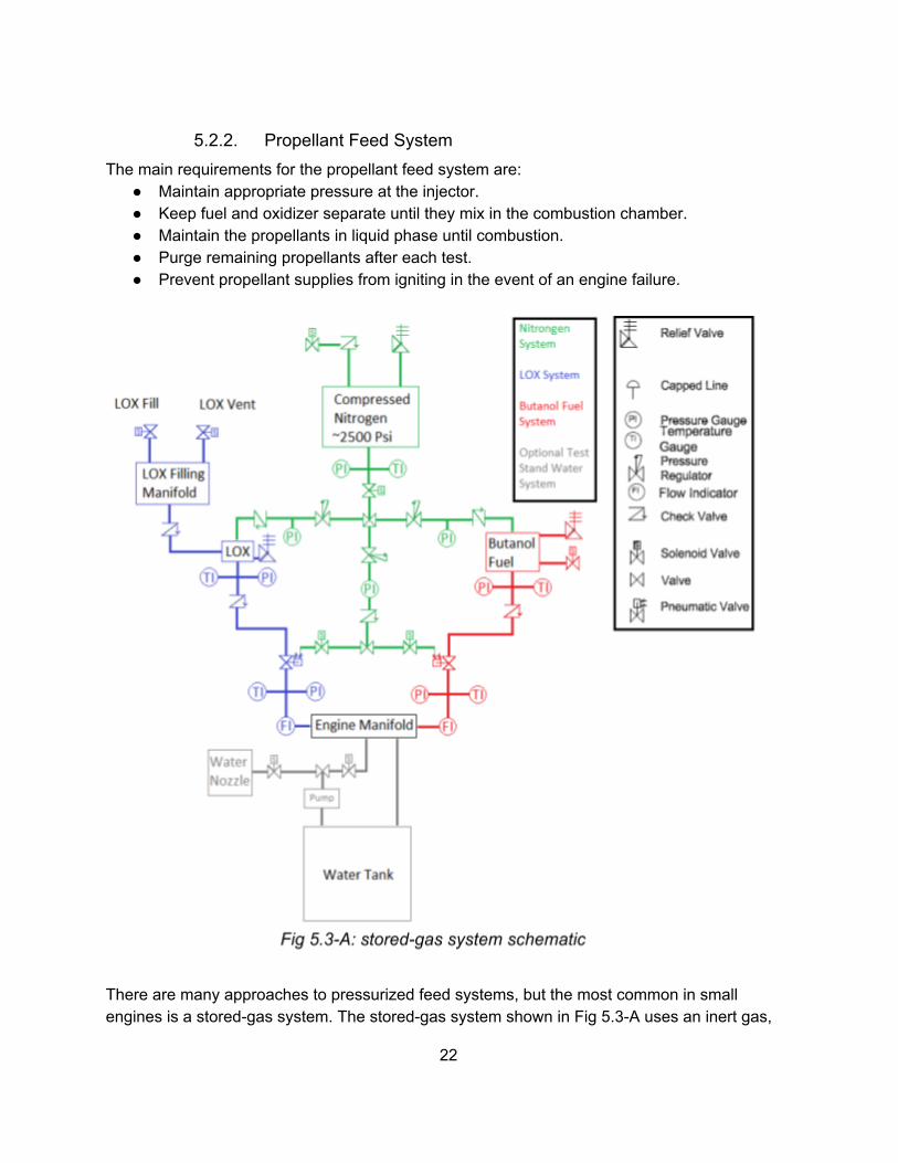
5.2.2. Propellant Feed System The main requirements for the propellant feed system are:
● Maintain appropriate pressure at the injector.● Keep fuel and oxidizer separate until they mix in the combustion chamber.● Maintain the propellants in liquid phase until combustion.● Purge remaining propellants after each test.● Prevent propellant supplies from igniting in the event of an engine failure.
There are many approaches to pressurized feed systems, but the most common in small engines is a stored-gas system. The stored-gas system shown in Fig 5.3-A uses an inert gas,
22

nitrogen, to fill the ullage - the empty space in the tanks - maintaining the correct pressure throughout the system.This nitrogen is also able to purge the propellant lines through the central purge line.
The check valves in the nitrogen lines, the relief valves on the tanks, and the high pressure of the nitrogen all work to prevent the propellants from flowing backward and mixing before they should. The redundant check valves in the lines also protect the propellant tanks from backflash, and the propellant and nitrogen tanks will be separated from the engine and test stand by a blast-proof barrier to protect against explosion.
In a flight rocket, we would want to precisely size the valves and piping, but for this test system we will oversize the plumbing to save money and accommodate a wider range of potential designs.
5.2.3. Fire suppression A large water tank will be mounted to the testing trailer. Before each test, this tank will be used to spray the ground around the trailer. During hot fires, water will spray below the rocket’s exhaust, wetting and cooling the ground and dampening noise. If a test goes wrong, water will rapidly spray into the burn box, dousing any flames to protect the propellant tanks.
5.3. Supporting Systems
5.3.1. Control center All hot-fire testing will be operated remotely from a control center. The control center will be a small shelter about 75 feet from the test trailer designed to protect personnel from noise and possible shrapnel in the event of an explosion. The center will be equipped with a generator, data acquisition units, a data collection laptop, and fire extinguishers All tests will be operated remotely and viewed with a series of cameras, keeping all test personnel a minimum of 30 meters, or within the hardened control center about 20 meters away.
5.3.2. Propellant Storage Our fuel, currently n-butyl alcohol, will be stored in a campus-approved location. Oxidizer will either be delivered as-needed on test days or stored in a dedicated liquid-oxygen storage shed with proper venting and clearances.
The liquid nitrogen used to pressurize the propellants during testing will be stored in a location with appropriate venting, as is standard procedure.
23
5.4. Testing Plan As we develop the engine, we will incrementally test the design, building up to full-duration burns to prove the engine for flight.
Cold Flow Test: Using pressurized water and nitrogen, we will see if the engine can withstand the pressure requirements for combustion. We will also examine flow patterns in the system.
Ignition Test: The maximum burn time for this test will be 2 seconds. The purpose is to see if we can safely ignite the engine. During this process, we will discover if our ignition system creates undesired flow patterns, unstable heat or any other hazards, and we will see if the pressure difference between the chamber and lines will stabilize.
Incremental Burn Tests: This test will still use water cooling to minimize the impact of the cooling system. We will incrementally increase the burn time up to a full burn of 20 seconds. We will measure the water temperature across the cooling jacket to quantify the heat transfer during combustion so we can refine the cooling system design. Additionally, we will record the output thrust and internal pressures to measure performance.
Cooling Tests: Having proven the engine can burn safely, we will test the final, regeneratively cooled design. Like before, we will increase the burn time incrementally, replacing any damaged components before each test. We will compare the performance of this engine to that of the water-cooled engine to quantify the impact of the regenerative cooling process.
Future: We can continue to use the test stand for testing new engine designs, and we may be able to open it up for other schools to use for their rocketry projects.
24

6. Flight RocketDesign Lead: Micah Makana Hicks
6.1. Overview For the 2017-2018 academic year the flight rocket team’s goal is to initiate design and testing of flight rocket components to be fully deployed in the 2018-2019 academic year. To facilitate this the flight rocket team intends to move members through the necessary certification processes, test a basic flight computer and associated instruments, develop and test an electromechanical recovery device, and to complete design work on the aero and structural components of the rocket. The certification process, while a necessary part of the project, does not contain engineering aspects and so is not discussed in depth.
General design specifications for the flight rocket at present call for a 4 fin rocket without body taper that is 10” in diameter and 15’ from nose to tail. Figure 6.1-A is an accurate representation of the rocket at the time of writing.
6.2. Support Structure The support structure is being optimized for weight, strength and fatigue life, and modularity. The support structure must be able to withstand loading at 5Gs, absorb vibrations to sufficiently protect internal components, allow for quick access to internal components, and, due to limited budget, must be conventional enough to keep costs low.
To accommodate these design elements, guage 8 aluminum pipe has been chosen as the basis of the structure (see Figure 6.2-A). This piping will be weight reduced by creating a pill shaped cut out pattern across the tube and the total weight of the support structure will be less than 15lbs. A honeycomb pattern was rejected since a sandwich panel system is required to achieve its characteristic properties, increasing construction complexity and cost. The chosen design was found to have fatigue life 1020 cycles at max loading, displacements of less than .01 mm, and a factor of safety at max loading of 7. (See Figure 6.2-B)
25
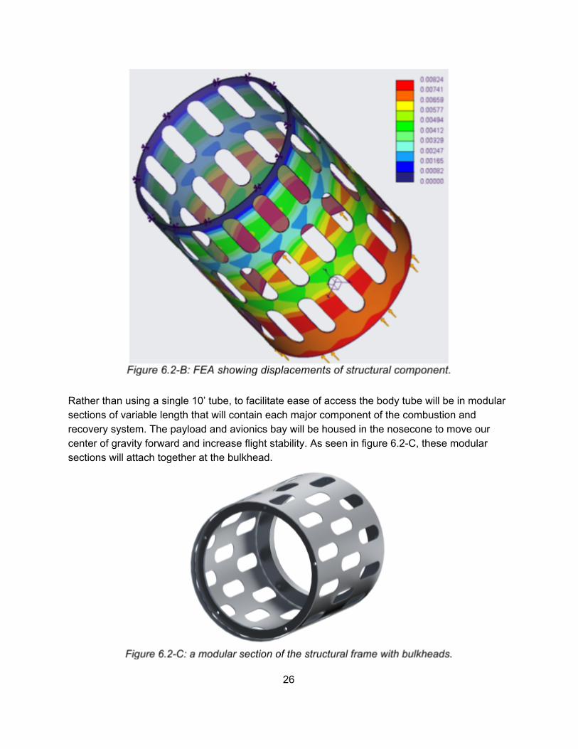
Rather than using a single 10’ tube, to facilitate ease of access the body tube will be in modular sections of variable length that will contain each major component of the combustion and recovery system. The payload and avionics bay will be housed in the nosecone to move our center of gravity forward and increase flight stability. As seen in figure 6.2-C, these modular sections will attach together at the bulkhead.
26

Modeling the vibration that will be experienced by OTRA’s flight rocket is complex and would require experimentation beyond the scope of this project. However, it can safely be assumed from existing research that the majority of vibration will come from gusts of wind and similar atmospheric perturbations and variable thrust provided by the engine. Under safe flight conditions, the greatest vibration problem will occur due to variable combustion. This problem is being addressed by multiple components, but in terms of structure it is be addressed by modifying the bulkhead of the section connecting the engine to the remainder of the flight rocket support structure. A final design has not been decided on but several options are being evaluated for effectiveness, cost, and ease of manufacture. Among these is a biomimicry solution based off the woodpecker's beak. A final design decision and associated calculations will be made by winter term; it is not in the project scope to manufacture this modified bulkhead this year due to time and monetary constraints.
6.3. Airframe The airframe will be constructed using fiberglass and attach directly to the structural support discussed in 6.2. The airframe is being designed to optimize for flight stability and drag characteristics.
Initial design work on the airframe was completed in Spring 2017 by using applied design of experiments (DOE) in CFD (typical result presented in Figure 6.3-A) and further wind-tunnel verification of the results. An optimized rocket was created based off the suggest DOE output and was found to have a drag coefficient of .2 in the CFD analysis.
To meet time and material constraints present at the time, only the nosecone was tested in the wind tunnel. This provides an appropriate approximation as skin drag was shown to be negligible in simulation. The results gave a drag coefficient of closer to .3 as shown in Table 6.3-A. This discrepancy is likely due to idealizations made in the model as well as noted manufacturing defects in the physical model including a visible misalignment between the two symmetrical halves of the nosecone that occurred during gluing.
27
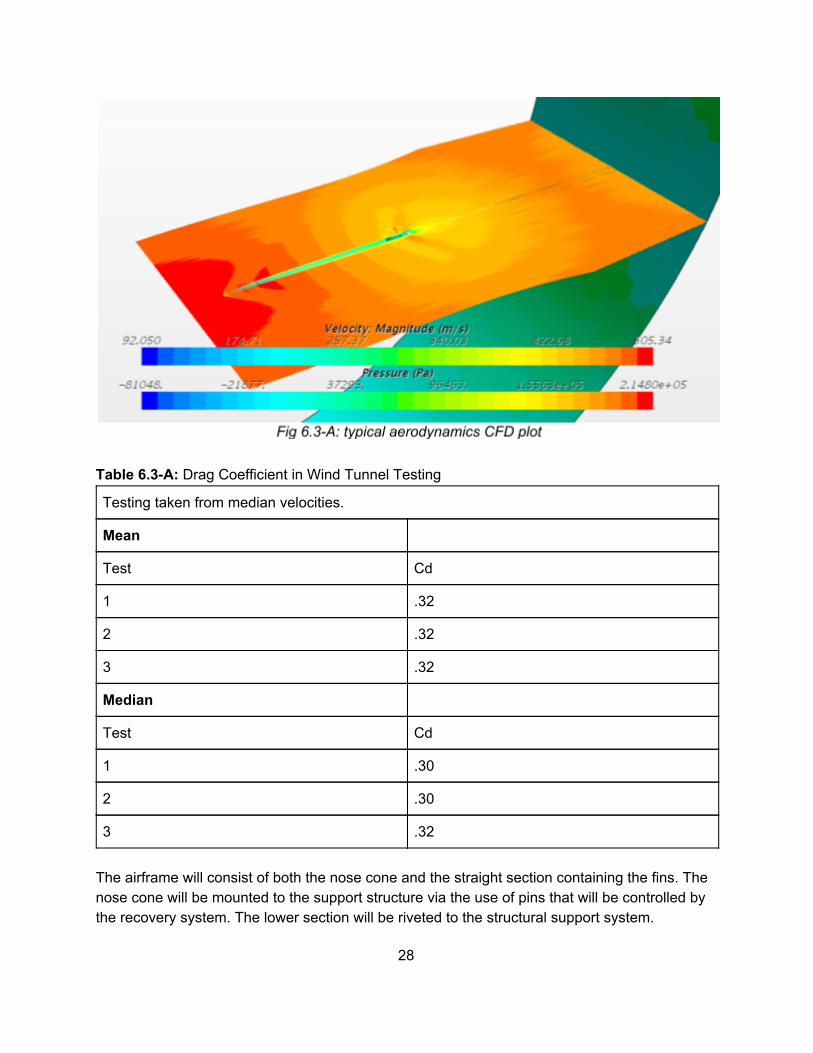
Table 6.3-A: Drag Coefficient in Wind Tunnel Testing
Testing taken from median velocities.
Mean
Test Cd
1 .32
2 .32
3 .32
Median
Test Cd
1 .30
2 .30
3 .32
The airframe will consist of both the nose cone and the straight section containing the fins. The nose cone will be mounted to the support structure via the use of pins that will be controlled by the recovery system. The lower section will be riveted to the structural support system.
28

6.4. AivionicsOTRA’s avionics system has three primary purposes in order of importance: data acquisition, transmission, and control. Data acquisition consists of instruments that will collect information on all critical flight systems, but primarily GPS and altitude requirements as outlined by ESRA for Spaceport America Cup. Transmission refers to the communication of this information to the ground station as required by ESRA and as desired by the club. Control avionics system are all those semi-autonomous systems on the rocket which will control its flight operations.
Data Acquisition To qualify for Spaceport America Cup, the avionics system must include a GPS with transmitter and a COTS altimeter used to control the rockets recovery systems. Spaceport America requires redundancy in this system. COTS flight computers are generally priced at less than $100 and offer the following capabilities:
● Altitude and GPS data-logging● Deployment of multiple parachutes● Radio telemetry● Event timers (staged recovery, booster separation, stage ignition, etc…)● Camera/video recording● Backup recovery system
However, such systems are inappropriate for the control and operation of a liquid fueled rocket and so this section of the proposal will focus on those elements required as a part of our own on-board flight computer.
In addition to the data collected by the COTS computer OTRA would like to collect data relating to the following: angle of attack, acceleration, velocity, mass flow, as well as replicating systems from the test stand. Namely, fuel temperatures before and after the cooling jacket, tank pressures, internal clock, mass flow timer, vibration and engine expansion rates.
In order to collect this d data, accelerometers, gyroscopes, flow sensors, temperature, strain, and pressure gauges will all be incorporated into the avionics schematic. See Figure 6.4-A for a P&ID of the overall system.
29

Transmission Data transmission will be controlled by a single radio transmitter. The radio transmitter will be used primarily to relay GPS location information to allow the team to locate the rocket after descent. Once we are assured that this information can be reliably transmitted, the team will begin to focus on streaming data from critical systems back to the ground station during flight. Due to FAA restrictions data transmission can only be from the rocket to ground station.
Transmission will require use of regulated radio bands. OTRA will work with the Ametuer Radio Club on campus to coordinate testing for required radio transmission licenses. At time of writing Brandon Camp is in possession of the required HAM radio license.
30

Control All of the control systems will rely on data generated by instruments and conveyed to the onboard flight computer. OTRA intends to control the ignition, burn rate, engine shutdown and recovery systems. These systems have been selected because they will directly control our performance in the competition and all are related to safety. OTRA intends to control the burn rate by using electric actuators to control mass flow of the butanol, nitrogen, and LOX systems. This will allow us to achieve proper ignition, slow our burn rate to ensure the desired apogee is reached, control our burn richness to ensure all fuel is used during ascent, and to control for catastrophic engine failure. Shutdown parameters include a highly variable strain rate that would indicate unstable combustion, the angle of attack or rapid changes in flight path, excessive temperatures or pressures detected at any point along the combustion system. The recovery system will be controlled by a servo system that controls the pins holding our nosecone in place and a spring loaded system which will eject the nosecone and chutes. The drogue chute will be deployed by the ejection of the nosecone from the main body. The drogue chute will be attached to the final chute but each will be stored separately so their deployment can be independent. The final chute will be deployed using a similar spring mechanism to that used to eject the nosecone. The recovery system’s deployment will be governed by three factors. In the event of normal descent, a negative (downward) acceleration, altitude, and angle of attack will govern the deployment of the chute. Deployment will also rely on receiving information of an engine shutdown as this will both prevent premature deployment and initiate deployment in the event of engine failure causing deviation from flight plan.
6.5. Recovery Our recovery system will be controlled by an electromechanical device that will act in two stages and be controlled by the avionics system discussed in the previous section. The system acts in two stages with the first being initiated by a servo that will retract the pins holding on the nosecone and a spring loaded system that will then apply force to eject the nosecone. For safety purposes, it is critical that this system not deploy before the rocket has begun descent and so the spring will be designed to provide only a small amount of force greater than that necessary to overcome the friction forces of the nosecone against the sidewall. The drogue chute will be attached with a kevlar string to both the nosecone, and the final chute. The string and attachment points will be rated for forces at least 3x those anticipated to ensure that the recovery system stays intact even in unforeseen circumstances.
31

The main chute will sit beneath a plate attached in a similar manner to the nosecone. A thin plate will be held down by pins controlled by a servo arm. At the appropriate altitude these pins will be retracted and it will be deployed in a similar manner to the nosecone with the drogue chute applying the force needed to eject it.
6.6. Manufacture and Testing This term the project priorities are in engine development and testing. Consequently, only limited manufacture and testing of these systems will be done. An actual full-scale flight rocket will not be tested in flight, however recovery and avionics systems will be tested in a level 1 or 2 certification rocket. The order of priority for manufacture is given below:
1. To scale airframe of rocket2. Structural components for non destructive testing.3. Avionics bay4. Electromechanical recovery device
Testing of a COTS flight computer to meet minimum contest requirements is a priority and will proceed separate from the processes listed above as it can be conducted using a 3D printed avionics bay and launched on any rocket available.
32

7. Project Plan
7.1. Project Schedule Our project will follow a schedule based on OIT’s senior project class schedule with work for each term divided roughly as follows.
● Fall term Design, fundraising, and approvals. ● Winter term Finalize design and fabrication. ● Spring term Finish fabrication and test.
The management of the individual tasks of the project follows an agile project methodology with weekly sprints organized around the Gantt chart and critical path of the project. At the weekly sprint meetings roadblocks are reviewed and resources allocated as necessary to catch up behind schedule tasks and start the next week’s tasks. Below is the high-level project schedule for each team in the 2017-2018 school year.
33

7.2. Contingency Plans The following tables outline each team’s critical tasks for each term and contingency plans in case the deadlines cannot be met.
Table 7.2-A Winter 2018 contingency plans
Team Task Contingency plan Engine
Design completed Manufacturing will be pushed back and fewer test fires performed. General materials can be assumed and should be purchased. E.g. hoses, stainless-steel, o-rings, etc.
Design Review - OTRA
Delay of schedule, fewer test fires will be performed.
Design Review - PSAS
Valuable insight will be lost, but we will press on. No delay of schedule
Injector head manufactured
If we have not manufactured a functioning injector head by mid-winter term, we will need to simplify our design, look for an outside manufacturer to complete it for us or do both.
Combustion Chamber manufactured
If this has not been manufactured, it is either due to complexity or manufacturability. If the part isn’t manufacturable, the design will be reconsidered.
Shell Manufactured If this item has not been manufactured, a simpler design can be implemented. The shell serves as the outside of the cooling channel, only the inside geometry must be preserved. For simplicity, the outside can be altered to meet needs.
Leak Test If a leak is found, the engine must be inspected, and engineers from OTRA must decide whether the solution is patchable. If the solution is not patchable, the part in question will need to be replaced in full. This will delay test fires.
Cold Flow Test If the engine fails the Cold Flow Test, it means that the pressure stress was too high. Causes for this could be Water Hammer, Unexpectedly high pressure from the tanks, material impurities, etc. Engineers will need to assess the damage, salvage what can be had, locate the problem, and solve.
34

Test Stand
Procure donations and discounts
Our grant money cannot cover the full retail cost of the current design. Sensor type and precision, fuel system sophistication, and control center complexity are all items that can be downsized in the event of a shortage of funds.
Kingsley field LOX training
Prerequisite for LOX handling. Pursue training from another source.
Kingsley field hush house testing
Prerequisite for on-campus testing. Pursue options for testing on private property such as the O’Connor lot west of campus.
Flight Rocket
Complete design of electromechanical recovery device
If this is not complete the team will need to plan for the use of a powder charge to initiate recovery.
35

Table 7.2-B Spring 2018 contingency plans
Team Task Contingency plan Engine
Hot Fire Test 1 - Ignition Testing
If ignition testing using the separate ignitor fails, we will revise the design and switch to an integrated fuel grain if necessary.
Start Full Hot Fire Tests
If hot fire testing fails, we will review the issue and revise the design. This may delay some test fires. If the engine consistently over heats and cannot be reasonably resolved with additional regenerative or film cooling, we will switch to an ablative lining material.
Test Stand
Build control center and complete trailer
The test design can be simplified as far as a test stand and fuel system directly on the ground with test personnel stationed behind a simple metal barrier.
Gain approval to test on campus
If testing on campus is no longer an option, we will pursue testing on private property.
Flight Rocket
Certify members through level III.
This is necessary to test our avionics system and for project progress in the 2019-2018 year.
36

7.3. Budget The following tables outline each team’s budget for the year.
Table 7.3-A Test Stand costs by subcomponent Project Subcomponent Item Qty Each Total Cost
Trailer
The trailer is the base of the test stand. It dampens noise and all components are directly mounted to it. Trailer 1 $2,000.00 $2,000.00
Strong, fine wire mesh, ft2 200 $0.75 $150.00
.125 sheet metal, ft2 100 $6.00 $600.00
Sound suppression panels, ft2 300 $0.50 $150.00
Subtotal: Bunker $2,900.00
Fire suppression
The fire suppression system is mounted on the trailer and functions as an automatic safety mechanism.
550 gallon tank 1 $824.67 $824.67
4 inch piping, ft 200 $4.57 $914.00
4 inch valve 2 $177.39 $354.78
Large shower head 4 $15.00 $60.00
Sprayer nozzles 10 $15.88 $158.80
1 inch piping, ft 150 $1.18 $177.30
1 inch electric valves 5 $150.00 $750.00
Subtotal: Fire Suppression $3,239.55
Engine Bay
The engine bay serves as the mount for the engine and contains the primary instrumentation.
6061 aluminum, ft3 1.5 $667.00 $1,000.50
Steel angle 3x3x.5, ft length 10 $20.00 $200.00
Steel plate 18x6x.75 3 $93.63 $280.89
Machining - - 150
Tooling - - 300
.325 bolts 30 $0.40 $12.00
.325 nuts 30 $0.27 $8.00
.500 bolts 20 $0.60 $12.00
.500 nuts 15 $0.93 $14.00
Linear bearings 4 $57.33 $229.32
37
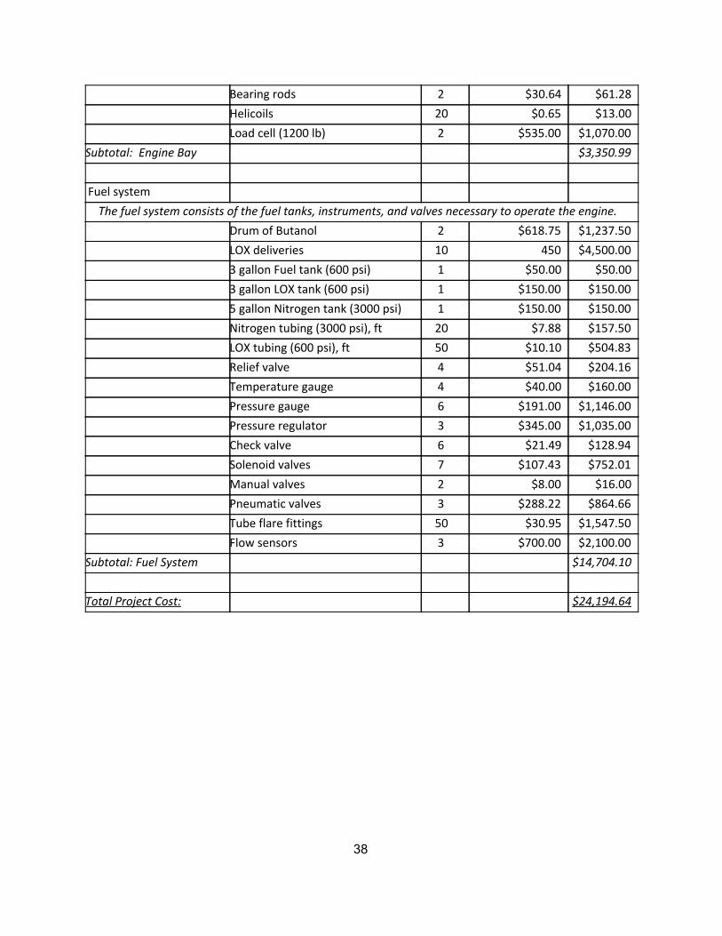
Bearing rods 2 $30.64 $61.28
Helicoils 20 $0.65 $13.00
Load cell (1200 lb) 2 $535.00 $1,070.00
Subtotal: Engine Bay $3,350.99
Fuel system
The fuel system consists of the fuel tanks, instruments, and valves necessary to operate the engine.
Drum of Butanol 2 $618.75 $1,237.50
LOX deliveries 10 450 $4,500.00
3 gallon Fuel tank (600 psi) 1 $50.00 $50.00
3 gallon LOX tank (600 psi) 1 $150.00 $150.00
5 gallon Nitrogen tank (3000 psi) 1 $150.00 $150.00
Nitrogen tubing (3000 psi), ft 20 $7.88 $157.50
LOX tubing (600 psi), ft 50 $10.10 $504.83
Relief valve 4 $51.04 $204.16
Temperature gauge 4 $40.00 $160.00
Pressure gauge 6 $191.00 $1,146.00
Pressure regulator 3 $345.00 $1,035.00
Check valve 6 $21.49 $128.94
Solenoid valves 7 $107.43 $752.01
Manual valves 2 $8.00 $16.00
Pneumatic valves 3 $288.22 $864.66
Tube flare fittings 50 $30.95 $1,547.50
Flow sensors 3 $700.00 $2,100.00
Subtotal: Fuel System $14,704.10
Total Project Cost: $24,194.64
38

Table 7.3-B Engine costs by subcomponent Project Subcomponent Item Qty Each Total Cost
Engine Raw Materials
The raw material from which the combustion chamber, injector head, and nozzle will be fabricated.
Stainless Steel 330 3 | 4" dia. x ft $878.40 $2,635.20
Beryllium Copper 3 | 4" dia. x ft $1,800.00 $5,400.00
Subtotal: Core Materials $8,035.20
Fuel
Our chosen oxidizer, fuel, and pressurizer.
n-Butanol 15 Gal $17.10 $256.50
Liquid Oxygen 3 Gal $240.00 $720.00
Nitrogen 3 Gal $84.00 $252.00
Subtotal: Fuel $1,228.50
O-Rings
O-Rings are a necessary sealant on various hoses and systems in the engine.
Astra Seal O-Ring 16.5 dia. $56.15 $926.64
Teflon O-ring 16.5 dia. $125.00 $2,062.50
High Pressure O-ring 16.5 dia. $248.24 $2,038.01
Subtotal: O-Rings $5,027.15
Instrumentation
Strain Gage 12 $68.00 $816.00
Combustion Chamber
Pressure Sensor
2 $1,140.00 $2,280.00
Combustion Chamber
Pressure Grease
2 $84.00 $168.00
Two Color Pyrometer 1 $3,600.00 $3,600.00
Subtotal: Instrumentation $6,864.00
Fasteners
Fasteners for various subcomponents including linkage to test stand and for the engine injector to
combustion chamber.
3/14 M.D. Bolt 30 $2.40 $72.00
1/6 M.D. Bolt 18 $2.40 $43.00
3/14 Nut 30 $2.40 $72.00
1/6 Nut 18 $2.40 $43.00
39

3/14 Washer 30 $1.20 $36.00
1/6 Washer 18 $1.20 $21.00
Flair Fitting 12 $31.80 $381.00
Flair Sleeving 12 $5.18 $62.00
Flair Nut 12 $2.10 $25.20
Screws 12 $3.01 $36.14
Alignment Pins 5 $2.50 $12.50
Subtotal: Fasteners $803.84
Tools
Additional tooling OTRA will have to purchase to manufacture the engine.
Flaring Tool 1 $450.00 $450.00
Machining Tooling $350.00 $350.00
Subtotal: Tooling $800.00
Miscellaneous
Describes machining and other associated costs that are not covered above.
Outsourcing Costs $4,500.00
Phenolic Resin $720.00
Stainless Hoses 3 $157.00 $471.00
Handling $250.00
Subtotal: Misc. $5,941.00
Total Project Cost: $28,699.69
40

8. Appendices
8.1. Appendix A: Propellant Comparison
41

Kinematic ValuesLOX & Butanol GOX & Butanol GOX & Ethanol
Apogee (meters) 10064.14877 10998.59252 7180.642899Apogee (feet) 33018.86184 36084.62229 36084.62229Maximum Velocity (m/s) 467.1115451 473.0492059 377.8338975Maximum Mach# (N/A) 1.444699454 1.474350342 1.14980631Maximum Thrust (N) 2611.47768 2549.531161 1887.748076Maximum Thrust (lbf) 587.083537 573.1574054 424.3826496Input Thrust (N) 2224.110809 2224.110809 2224.110809Input Thrust (lbf) 500 500 500 Burn Time (seconds) 18.25 19.75 17.1 Total Impulse (N*s) 40629.30805 43627.66465 30306.65294
Kinematic Design ParametersStarting Alt (m) 1401Design Alt (m) 1401Init. Temperature K 300.93
42

FuelsLOX & Butanol GOX & Butanol GOX & Ethanol
C. Pressure psi 200 300 300C. Pressure kPa 1378.952 2068.428 2068.428C. Temp F 5,479.39 5641.58984 5220C. Temp C 3026.327778 3116.4388 2882.222222Isp S.L. (sec) 238.86 257.94 248Mixture Ratio 1.934 1.943 1.645Gamma 1.1692 1.1732 1.807Char. Velocity (m/s) 1.740874146 1.765060965 1.709683767S.L. Exit Vel. (m/s) 2343.2166 2530.3914 2432.88Thrust Coefficient 1.346 1.4336 1.423Rgas. exit 343 347.3 344.8Prop.Mdot (kg/s) 0.949169616 0.878958884 0.914188123Fuel Mdot (kg/s) 0.323507027 0.298660851 0.34562878Oxidizer Mdot (kg/s) 0.625662589 0.580298033 0.568559343Top Isp (sec) 280.4616493 295.6805498 210.4938707
Mass Analysis LOX & Butanol GOX & Butanol GOX & Ethanol
MetricTotal Init. Mass (kg) 51.32030606 51.37337633 49.61616092Mass Fuel (kg) 5.896696 5.896696 5.896696Mass Oxidizer (kg) 11.40421006 11.45728033 9.70006492Mass Propellent (kg) 17.30090606 17.35397633 15.59676092Rocket Mass (kg) 34.0194 34.0194 34.0194
English Total Init. Mass (lbm) 113.142 113.259 109.385Mass Fuel (lbm) 13 13 13Mass Oxidizer (lbm) 25.142 25.259 21.385Mass Propellent (lbm) 38.142 38.259 34.385Rocket Mass (lbm) 75 75 75
43

8.2. Appendix B: Reference Documents The following appended documents are referenced within this proposal and were sourced from the links below:
● OTRA White Paper Produced by OTRA
● FAA Ameteur Rocketry Regulations https://tinyurl.com/y7wbn85h
● Fisher Scientific n-Butanol SDS https://tinyurl.com/ycyr3zaw
● Linde Group Compressed Oxygen SDS https://tinyurl.com/ycwgv5y6
44

1
Document Last Revision: 4 OCT. 2017
Document Review Schedule: Annual
Authors: Brandon Camp (Safety Officer), Micah Hicks (Flight Rocket Lead), David Minar (President)
Document Number: GEN-SAF-0001
Document Title: OTRA Safety Approach and Rocket Project Specifics
2
Contents OTRA Safety Mission Statement ................................................................................................................... 3
Introduction .................................................................................................................................................. 3
Specific Material Concerns............................................................................................................................ 4
Specific Process Concerns ............................................................................................................................. 7
Testing ....................................................................................................................................................... 7
Flight ......................................................................................................................................................... 7
Materials Handling .................................................................................................................................... 8
Storage ...................................................................................................................................................... 8
Manufacturing .......................................................................................................................................... 8
Fire ............................................................................................................................................................ 8
List of Key Safety Documents ........................................................................................................................ 8
Glossary ......................................................................................................................................................... 9

3
OTRA Safety Mission Statement For Oregon Tech Rocketry and Aerospace (OTRA) safety is built into every aspect of our work from design to flight. OTRA will strive to set the gold standard in safety of student lead projects here at OIT and nationally. OTRA will demonstrate this commitment by our track record and by developing internal safety procedures and directives as well as maintaining a database of outside safety rules and regulations.
Introduction The approach to safety taken by OTRA can be broken into six categories—several of which may be appropriate at any given time. These categories are: safety by regulation, safety by imitation, safety by oversight, safety by design, safety by process, and safety by certification.
OTRA is fundamentally an engineering project. What we do will often be regulated by federal and state agencies: this is safety by regulation. These include the FAA CFR 101.21-29, the NFPA (section 1127), OSHA regulations regarding the storage and handling of our fuels, local fire codes, manufacturer MSDS, contest rules and regulations developed by ERSA/IREC, and safety regulations developed and maintained by Tripoli Rocketry (initial flight tests), Reaction Research Society (experimental flight tests), among others.
Safety by imitation recognizes that OTRA is a junior member in the field of rocketry and can learn by imitating the safety practices of other clubs and teams involved in the field. While there are inherent dangers, the contest for which OTRA is designing and the field of amateur rocketry in general is remarkably safe. ESRA/IREC has hosted the contest without incident since 2002, RRS has not had an accident since their founding in 1943, and according to Oregon Rocketry there has not been a single serious injury or fatality associated with Tripoli Rocketry clubs in its 50 years 1. We are in contact with both Portland State University Aerospace Society and Michigan Aeronautical Science Association regarding their own safety procedures and will continue to develop our contacts with other clubs.
As OTRA designs, builds, and tests our rocket we will have a great deal of oversight. Following this and seeking it out is what we mean by safety by oversight. The first line of oversight is our club advisor Sean Sloan, then our senior project advisor Dongbin Lee, oversight during the manufacturing process will be provided by TAs and MMET faculty, oversight during the launches will be provided by certified Tripoli members, RRS members and at the Spaceport Cup America by a variety of aerospace professionals who make up the judging and operations staff. Safety by oversight includes periodic design reviews, proposals, and oral and written explanations that OTRA will have to submit in order to test and fly our rocket.
Safety by design is the student lead initiative to follow industry standard regulations regarding safety in design applications. These primarily relate to factors of safety in structural and pressurized components, in house design verification, selecting nonhazardous materials,
1 Oregon Rocketry. “Who We Are.” Oregon Rocketry. http://www.oregonrocketry.com/?page_id=4 (7 Oct. 2017)

4
simulating stresses on our components before testing, and a general mentality of focusing on safety and developing safety guidelines as we design the rocket. For instance in our selection of fuels, safety was a guiding factor. Butanol was selected not only because of its combustion properties, but also because it can be made from biofuels reducing environmental hazards and has no listed injuries or deaths with OSHA. Similarly LOX was chosen due to safety concerns brought up in technical advice given by Blue Origin—a large player in private aerospace.
In all of engineering and industry in general, processes are a primary concern with safety—which is why there are lock out/tag outs and similar. To give a domestic example a gas heater poses substantial, innate risk to a home and its occupants. However, by following predetermined processes operation and maintenance of these is quite safe. A homeowner would be ill-advised to relight a pilot light on a gas heater that has been out for some time without first ventilating the area. Failure to do this could result in an explosion, but by doing this the innate risk of explosion posed by natural gas is mitigated. Similarly, by developing processes for the activities we do we can mitigate the innate danger of these activities. For instance, manufacture using composite materials poses specific dangers: inhalation of toxic fumes, skin and eye irritation, damage to vacuum equipment. Consequently, OTRA has created an instruction manual for composites manufacture which is based off industry experience by David Minar and Micah Hicks and experience in a MECH 407 Advanced Composites class taught by Prof. Joe Stuart. This is required reading for anyone manufacturing with composites in our club—this goes above the procedures of other clubs using the composites lab. Actions of this sort comprise safety by process and it is key to keeping the club members and property safe.
Both for professional and safety reasons, OTRA will pursue safety related certifications where relevant and feasible. Thus, we will ensure safety by certification. OTRA member Jason Peters is working with Kingsley Field and the 173rd fighter squadron to organize training for OTRA in LOX handling and their engine testing procedures. Other examples are the progressive flight certifications team members will be receiving through Tripoli and Oregon Rocketry that focus on design and launch safety and include written exams, rocket inspection, and safe launch and recover criteria. In some cases, certification will be the result of OTRA developed training.
Specific Material Concerns Access: Access to all materials is contingent on approval from first Risk Management (if they deem it necessary), second Lab Managers and Campus Safety, third club advisors and OTRA officers. Access to most materials will be granted on a per user basis. For most materials this will require a lab pass and OTRA advisor and officer consent. LOX, N2, and butanol will require training. Access to N2 will be granted only on a per use basis.
Liquid Oxygen (LOX): serves as the oxidizer in our combustion cycle.
Dangers: LOX is extremely cold (-297°F) and can cause burns as well as reduce thestrength of many materials. If vented in an enclosed environment can potentially cause oxygen saturated atmosphere posing fire and inhalation hazards. Long term storage of LOX results in increasing pressure in tanks which if not properly fitted with relief valve can result in rupture of tank.

5
Prevention: LOX will not be stored by OTRA. LOX will not be stored in enclosed environments for at any time. LOX will only be purchased in quantities needed for scheduled tests. LOX will be delivered as close to test date as possible (safety by process). Any excess LOX at a test location will be removed as soon as possible by professionals. OSHA regulations regarding Personal Protective Equipment (PPE) and handling will be strictly followed (safety by regulation). PPE includes cryogenic-safe gloves, face shields & safety glasses, fire resistant coveralls. Further regulation can be found in SAF-TECH-0001. Handling training will be received from Air Force or other qualified institution. Handling of LOX will only be performed by certified individuals (safety by certification).
Contingency: In event of injury a first aid kit will be kept on hand with warm packs included. In the event of fire or explosion, fire extinguishers are kept on hand any time LOX is used and test stand has integrated fire suppression system (safety by design).
Storage: As LOX must be maintained at low temperatures, all LOX has a limited shelf life. Adequate ventilation is necessary for storage to enable the gas to be released as it warms and expands. To avoid these complications, OTRA will purchase LOX locally from Airgas for same day use and return. Unused LOX can be safely vented to atmosphere to empty the vessel or returned to Airgas.
Butanol: is our rocket fuel.
Dangers: OSHA lists no associated deaths or injuries with this substance. It is an organic biofuel and nontoxic. Dangers are primarily fire and explosion. It is a 1-3-1-0 substance and generally regarded as safer than gasoline (stored by FSAE and BajaSAE on campus) due to its much higher flashpoint and lower combustibility.
Prevention: OSHA handling regulations to be followed at all times (safety by regulation). In general, it is to be treated like gasoline. Sealed containers, kept away from areas in which flammable operations are being performed, etc.
Contingency: The fire department will be notified a week before and the day of any scheduled test (safety by process). No less than two members will stand at ready with fire extinguishers at each test and will be trained in their use (safety by process). Test stand will contain integrated fire suppression system (safety by design). OTRA has reached out to civil engineering professors and the Klamath County Fire Marshall for assistance on developing and implementing a fire prevention plan.
Storage: Unpressurized butanol can be safely stored and handled in the same manner as any alcohol solvent.
Composite fibers include glass and carbon fiber weaves, tape, and tow. These will be used in the manufacture of the body tube and support structure.
Dangers: Primarily dangers come from the manufacturing process rather than material itself. Fine carbon fiber and glass dusts are respiratory system, eye, and skin irritant.
Prevention: Best practice composite labs safety will be followed and team members will be instructed of dangers, PPE, and warning signs (safety by process). Basic lab safety procedures from OIT professors will be followed including ventilation and the buddy system (safety by process). OIT Faculty & Campus will be aware when OTRA members are using the composites lab. Any member using the composites lab will have received a

6
lab pass from Campus Safety. OSHA has not developed any specific guidance on composites. The composites lab is in compliance with OSHA Oregon guidance.
Contingency: In the event of respiratory problems, members will be instructed to leave the lab immediately. Any student who demonstrates irritation, experiences dizziness, respiratory problems, or other negative reactions to composite fibers will be required to use PPE including respirator and goggles. If eye or skin irritation occurs, wash stations are readily available and members will be instructed to rinse for up to 15 minutes.
Storage: Storage of fibers and tows pose no dangers and already done on campus. Any purchased composite fibers will be labeled and stored with existing in the Composites Lab (CO 118).
Composite resins including epoxies, polymers, phenolics and similar will be used in manufacture of body tube, structural components, and similar.
Dangers: Most resins and curing agents are toxic if ingested and before fully cured will emit fumes that can be dangerous to health if not vented. Allergic reaction (skin contact/ingestion), poisoning (ingestion), liver damage (ingestion) are possible. Many resins are carcinogenic, and can cause bronchitis and pulmonary edema (prolonged inhalation). Curing process generates heat which can be danger if uncured resin stored next to combustibles.
Prevention: OSHA and lab safety standards will be followed (safety by regulation/process). These include proper use of PPE, inspection of lab equipment before use (ventilation and wash stations), buddy system, and in-house training (safety by certification). OSHA has not developed any specific guidance on composites. The composites lab is in compliance with OSHA Oregon guidance.
Contingency: Poison control center numbers are posted around lab in case of ingestion. Wash stations will be used in case of skin irritation and 911 called in case of allergic reaction. Inhalation concerns can only be addressed with PPE, proper lab procedure and engineering controls (ventilation).
Storage: Storage of these chemicals is routine and already done on campus. OTRA will consult with lab managers and Risk Management regarding storage. Requisite labels are present in the lab and all chemicals purchased by the club will be labeled and stored in designated part of Composites Lab (CO 118).
Nitrogen gas will be used to purge the plumbing systems of the engine between test fires and to leak test the system.
Dangers: N2 compressed gas is nontoxic, nonflammable, and is treated by OSHA as a general compressed gas. If vented in a confined space N2 may displace oxygen creating a suffocation hazard.
Prevention: The dangers of N2 are those common to all compressed gasses—primarily failure of the pressurized vessel. OTRA will follow OSHA regulations contained in 1910.101 (safety by regulation). If Risk Management stores N2 in a confined area, the storage area will be vented for 30 minutes before entry. Permit required confined space rules will be followed. An N2 detector will be purchased for this purpose.

7
Contingency: In the event of an OTRA member starting to experience lightheadedness, dizziness or other low oxygen symptoms, they will be escorted to an area with breathable air.
Storage: We will identify with Risk Management an appropriate venue for storage of the gas. If such cannot be found due to the Cornett re-model N2 will be purchased from Airgas locally for same day use and return.
Specific Process Concerns Testing Testing is where most catastrophic safety hazards are present. OTRA will engage in two very different kinds of testing: flight testing and engine testing.
Flight testing will be governed by Tripoli and Reaction Research Society (RRS) rules (safety by regulation) and design review by officials from those organizations (safety by oversight) in addition to the safety considerations that will have been addressed in design process (safety by design) and by advisors to the club (safety by oversight). Because the primary safety controls on flight tests cannot be quickly addressed, the reader is deferred to the List of Safety Documents below, particularly those by Tripoli regarding range safety and experimental rocket safety.
Engine testing is done in house by OTRA and this will be addressed in this subsection.
Dangers: Fire, projectiles, acoustic injury, LOX handling dangers, & high-pressure handling dangers.
Prevention: OTRA has after consultation with other clubs and Blue Origin begun developing a testing schedule that takes the dangers possible in a full test and spreads them into smaller controllable chunks (safety by process). Initial Cold-Flow testing will be done with pressurized water and nitrogen to test the pressure viability of the engine. This insures the systems integrity without chance of combustion. Initial hot fire testing will be performed with minimal fuel loaded and 1-second burns. This requires only ounces of fuel and so both fire and rupture hazards are minimal. The test stand is being designed with blast shields, fire suppression, and addition safety shut off features. Any approved test site will have a Fire Marshall approved fire prevention plan. OTRA members will be at a distance of 30m from the test stand behind a safety structure wearing PPE before countdown procedures starts. A lockout/tagout procedure will be used to insure all members are accounted for. Testing will end immediately if any member requests so for safety reasons.
Contingency: In the event of injury a first aid kit is on hand and members will be trained in First Aid Procedures. Due to the distance members will be from the engine during testing, any injuries will be minor and are extremely unlikely, but both Skylakes and the Fire department will be notified before testing.
Flight Flight safety will be addressed primarily by the range safety officers of the organization sponsoring the launch—for the year 2017-2018 this is likely to only be Tripoli Rocketry

8
Association. Tripoli has decades of experience without accident and works closely with the FAA, NFPA, and OSHA to ensure that each launch is successful and safe.
Materials Handling Materials handling presents dangers both in the transportation of materials or the loading unloading of their containers. At present the only material which poses danger in its transportation to and from flight sites or testing is LOX. The dangers LOX presents to students is mitigated by the use of proper PPE (safety by regulation), the training OTRA members will be required to receive from Air Force or other organization before handling (safety by certification), and the same-day use policy OTRA maintains regarding its use and storage (safety by process).
Storage OTRA will not store materials that are hazardous in passive storage. Materials that are hazardous to passively handle will be handled by certified individuals (safety by certification). When OTRA does intend to store materials or chemicals, an appropriate location will be identified in consultation with lab managers and Risk Management well in advance of purchase.
Manufacturing Dangers due to manufacturing will be approached primarily through safety through certification, which in this case means classwork. Students who have not taken the appropriate classes—as an example MFG 103 for welding—will not be allowed to use the equipment that class teaches. Beyond this, the appropriate lab pass will be required and OIT’s lab and safety policies followed. OTRA is not engaged in any exotic manufacture of parts and for many components will be contracting out the work.
Fire Preventing fire is key to the safety of this project. As such we have reached out the Fire Marshall for help in developing a fire prevention plan (safety by oversite), are seeking training regarding handling of flammables and in the containment of small fires (safety by certification), are creating our test schedule with fire prevention as the key concern (safety by process), and are integrating a fire suppression system into the test stand (safety by design).
List of Key Safety Documents Author Organization
Document Title Document Number
Doc Status
OTRA Composite Lab Safety SAF-MAN-0001 Approved OTRA LOX Safety SAF-SHEET-0001 Pending Rev. Tripoli Range Safety SAF-REG-0001 Approved Tripoli Metal in Rockets SAF-MAN-0002 Approved Tripoli Range Safety Officer Req. SAF-REG-0002 Approved Tripoli Research Safety Code SAF-REG-0003 Approved Tripoli Safe Launch Practices SAF-REG-0004 Approved NFPA Rocket Fire Reg. 1127 SAF-REG-0005 Approved Tripoli High Power Safety Code SAF-REG-0006 Approved OTRA General Lab Safety SAF-MAN-0003 Developing OTRA Test Schedule SAF-TECH-0002 Developing

9
Bureau Safety and Health Montana
Handling Pressure Vessels SAF-TECH-0003 Approved
OTRA Test Safety Processes SAF-TECH-0004 Developing OTRA Engine Test Fire Prevention Plan SAF-TECH-0005 Developing OTRA Materials Handling and Storage SAF-TECH-0006 Developing DOW SDS n-Butanol SAF-TECH-0007 Approved OSHA Confined Space Entry SAF-REG-0007 Approved OTRA Model Rocket Safety Code SAF-SHEET-0002 Approved OTRA Pressurized Tank Safety SAF -SHEET-0003 Pending Rev.
Glossary Confined Space: OSHA defines a confined space as any area that is not designed or suitable for continuous human habitation. Examples include: tanks, vessels, silos, storage bins, hoppers, vaults, pits, manholes, tunnels, equipment housings, ductwork, pipelines, etc.
Permit Required Confined Space: refers to any confined space that has one or more of the following characteristics: (1) Contains or has a potential to contain a hazardous atmosphere; (2) Contains a material that has the potential for engulfing an entrant; (3) Has an internal configuration such that an entrant could be trapped or asphyxiated by inwardly converging walls or by a floor which slopes downward and tapers to a smaller cross-section; or (4) Contains any other recognized serious safety or health hazard.
Passive Storage: containers are tightly closed and may not be filled or emptied or opened for any reason while they are being stored.

888
14 CFR Ch. I (1–1–16 Edition) § 101.15
(2) More than 500 feet above the sur-face of the earth;
(3) From an area where the groundvisibility is less than three miles; or
(4) Within five miles of the boundaryof any airport.
(b) Paragraph (a) of this section doesnot apply to the operation of a balloon or kite below the top of any structure and within 250 feet of it, if that shield-ed operation does not obscure any lighting on the structure.
§ 101.15 Notice requirements.
No person may operate an unshieldedmoored balloon or kite more than 150 feet above the surface of the earth un-less, at least 24 hours before beginning the operation, he gives the following information to the FAA ATC facility that is nearest to the place of intended operation:
(a) The names and addresses of theowners and operators.
(b) The size of the balloon or the sizeand weight of the kite.
(c) The location of the operation.(d) The height above the surface of
the earth at which the balloon or kite is to be operated.
(e) The date, time, and duration ofthe operation.
§ 101.17 Lighting and marking require-ments.
(a) No person may operate a mooredballoon or kite, between sunset and sunrise unless the balloon or kite, and its mooring lines, are lighted so as to give a visual warning equal to that re-quired for obstructions to air naviga-tion in the FAA publication ‘‘Obstruc-tion Marking and Lighting’’.
(b) No person may operate a mooredballoon or kite between sunrise and sunset unless its mooring lines have colored pennants or streamers attached at not more than 50 foot intervals be-ginning at 150 feet above the surface of the earth and visible for at least one mile.
(Sec. 6(c), Department of Transportation Act (49 U.S.C. 1655(c)))
[Doc. No. 1580, 28 FR 6722, June 29, 1963, as amended by Amdt. 101–4, 39 FR 22252, June 21, 1974]
§ 101.19 Rapid deflation device.No person may operate a moored bal-
loon unless it has a device that will automatically and rapidly deflate the balloon if it escapes from its moorings. If the device does not function prop-erly, the operator shall immediately notify the nearest ATC facility of the location and time of the escape and the estimated flight path of the balloon.
Subpart C— Amateur Rockets § 101.21 Applicability.
(a) This subpart applies to operatingunmanned rockets. However, a person operating an unmanned rocket within a restricted area must comply with § 101.25(b)(7)(ii) and with any additionallimitations imposed by the using orcontrolling agency.
(b) A person operating an unmannedrocket other than an amateur rocket as defined in § 1.1 of this chapter must comply with 14 CFR Chapter III.
[Doc. No. FAA–2007–27390, 73 FR 73781, Dec. 4, 2008]
§ 101.22 Definitions.The following definitions apply to
this subpart: (a) Class 1—Model Rocket means an
amateur rocket that: (1) Uses no more than 125 grams (4.4
ounces) of propellant; (2) Uses a slow-burning propellant;(3) Is made of paper, wood, or break-
able plastic; (4) Contains no substantial metal
parts; and (5) Weighs no more than 1,500 grams
(53 ounces), including the propellant. (b) Class 2—High-Power Rocket means
an amateur rocket other than a model rocket that is propelled by a motor or motors having a combined total im-pulse of 40,960 Newton-seconds (9,208 pound-seconds) or less.
(c) Class 3—Advanced High-PowerRocket means an amateur rocket other than a model rocket or high-power rocket.
[Doc. No. FAA–2007–27390, 73 FR 73781, Dec. 4, 2008]
§ 101.23 General operating limitations.(a) You must operate an amateur
rocket in such a manner that it:
VerDate Sep<11>2014 15:21 Feb 04, 2016 Jkt 238047 PO 00000 Frm 00898 Fmt 8010 Sfmt 8010 Q:\14\14V2.TXT 31lpow
ell o
n D
SK
54D
XV
N1O
FR
with
$$_
JOB

889
Federal Aviation Administration, DOT § 101.29
(1) Is launched on a suborbital trajec-tory;
(2) When launched, must not crossinto the territory of a foreign country unless an agreement is in place be-tween the United States and the coun-try of concern;
(3) Is unmanned; and(4) Does not create a hazard to per-
sons, property, or other aircraft. (b) The FAA may specify additional
operating limitations necessary to en-sure that air traffic is not adversely af-fected, and public safety is not jeopard-ized.
[Doc. No. FAA–2007–27390, 73 FR 73781, Dec. 4, 2008]
§ 101.25 Operating limitations for Class 2-High Power Rockets and Class 3-Advanced High Power Rock-ets.
When operating Class 2-High Power Rockets or Class 3-Advanced High Power Rockets, you must comply with the General Operating Limitations of § 101.23. In addition, you must not oper-ate Class 2-High Power Rockets or Class3-Advanced High Power Rockets—
(a) At any altitude where clouds orobscuring phenomena of more than five-tenths coverage prevails;
(b) At any altitude where the hori-zontal visibility is less than five miles;
(c) Into any cloud;(d) Between sunset and sunrise with-
out prior authorization from the FAA; (e) Within 9.26 kilometers (5 nautical
miles) of any airport boundary without prior authorization from the FAA;
(f) In controlled airspace withoutprior authorization from the FAA;
(g) Unless you observe the greater ofthe following separation distances from any person or property that is not asso-ciated with the operations:
(1) Not less than one-quarter themaximum expected altitude;
(2) 457 meters (1,500 ft.);(h) Unless a person at least eighteen
years old is present, is charged with en-suring the safety of the operation, and has final approval authority for initi-ating high-power rocket flight; and
(i) Unless reasonable precautions areprovided to report and control a fire caused by rocket activities.
[74 FR 38092, July 31, 2009, as amended by Amdt. 101–8, 74 FR 47435, Sept. 16, 2009]
§ 101.27 ATC notification for alllaunches.
No person may operate an unmanned rocket other than a Class 1—Model Rocket unless that person gives the following information to the FAA ATC facility nearest to the place of in-tended operation no less than 24 hours before and no more than three days be-fore beginning the operation:
(a) The name and address of the oper-ator; except when there are multiple participants at a single event, the name and address of the person so des-ignated as the event launch coordi-nator, whose duties include coordina-tion of the required launch data esti-mates and coordinating the launch event;
(b) Date and time the activity willbegin;
(c) Radius of the affected area on theground in nautical miles;
(d) Location of the center of the af-fected area in latitude and longitude coordinates;
(e) Highest affected altitude;(f) Duration of the activity;(g) Any other pertinent information
requested by the ATC facility.
[Doc. No. FAA–2007–27390, 73 FR 73781, Dec. 4, 2008, as amended at Doc. No. FAA–2007–27390, 74 FR 31843, July 6, 2009]
§ 101.29 Information requirements.(a) Class 2—High-Power Rockets. When
a Class 2—High-Power Rocket requires a certificate of waiver or authoriza-tion, the person planning the operation must provide the information below on each type of rocket to the FAA at least 45 days before the proposed operation. The FAA may request additional infor-mation if necessary to ensure the pro-posed operations can be safely con-ducted. The information shall include for each type of Class 2 rocket expected to be flown:
(1) Estimated number of rockets,(2) Type of propulsion (liquid or
solid), fuel(s) and oxidizer(s), (3) Description of the launcher(s)
planned to be used, including any air-borne platform(s),
(4) Description of recovery system,(5) Highest altitude, above ground
level, expected to be reached, (6) Launch site latitude, longitude,
and elevation, and
VerDate Sep<11>2014 15:21 Feb 04, 2016 Jkt 238047 PO 00000 Frm 00899 Fmt 8010 Sfmt 8010 Q:\14\14V2.TXT 31lpow
ell o
n D
SK
54D
XV
N1O
FR
with
$$_
JOB

890
14 CFR Ch. I (1–1–16 Edition) § 101.31
(7) Any additional safety proceduresthat will be followed.
(b) Class 3—Advanced High-Power Rockets. When a Class 3—Advanced High-Power Rocket requires a certifi-cate of waiver or authorization the per-son planning the operation must pro-vide the information below for each type of rocket to the FAA at least 45 days before the proposed operation. The FAA may request additional infor-mation if necessary to ensure the pro-posed operations can be safely con-ducted. The information shall include for each type of Class 3 rocket expected to be flown:
(1) The information requirements ofparagraph (a) of this section,
(2) Maximum possible range,(3) The dynamic stability character-
istics for the entire flight profile, (4) A description of all major rocket
systems, including structural, pneu-matic, propellant, propulsion, ignition, electrical, avionics, recovery, wind- weighting, flight control, and tracking,
(5) A description of other supportequipment necessary for a safe oper-ation,
(6) The planned flight profile and se-quence of events,
(7) All nominal impact areas, includ-ing those for any spent motors and other discarded hardware, within three standard deviations of the mean im-pact point,
(8) Launch commit criteria,(9) Countdown procedures, and(10) Mishap procedures.
[Doc. No. FAA–2007–27390, 73 FR 73781, Dec. 4, 2008, as amended at Doc. No. FAA–2007–27390, 74 FR 31843, July 6, 2009]
Subpart D—Unmanned Free Balloons
SOURCE: Docket No. 1457, 29 FR 47, Jan. 3, 1964, unless otherwise noted.
§ 101.31 Applicability.This subpart applies to the operation
of unmanned free balloons. However, a person operating an unmanned free bal-loon within a restricted area must comply only with § 101.33 (d) and (e) and with any additional limitations that are imposed by the using or controlling agency, as appropriate.
§ 101.33 Operating limitations.
No person may operate an unmannedfree balloon—
(a) Unless otherwise authorized byATC, below 2,000 feet above the surface within the lateral boundaries of the surface areas of Class B, Class C, Class D, or Class E airspace designated for an airport;
(b) At any altitude where there areclouds or obscuring phenomena of more than five-tenths coverage;
(c) At any altitude below 60,000 feetstandard pressure altitude where the horizontal visibility is less than five miles;
(d) During the first 1,000 feet of as-cent, over a congested area of a city, town, or settlement or an open-air as-sembly of persons not associated with the operation; or
(e) In such a manner that impact ofthe balloon, or part thereof including its payload, with the surface creates a hazard to persons or property not asso-ciated with the operation.
[Doc. No. 1457, 29 FR 47, Jan. 3, 1964, as amended by Amdt. 101–5, 56 FR 65662, Dec. 17, 1991]
§ 101.35 Equipment and marking re-quirements.
(a) No person may operate an un-manned free balloon unless—
(1) It is equipped with at least twopayload cut-down systems or devices that operate independently of each other;
(2) At least two methods, systems,devices, or combinations thereof, that function independently of each other, are employed for terminating the flight of the balloon envelope; and
(3) The balloon envelope is equippedwith a radar reflective device(s) or ma-terial that will present an echo to sur-face radar operating in the 200 MHz to 2700 MHz frequency range.
The operator shall activate the appro-priate devices required by paragraphs (a) (1) and (2) of this section whenweather conditions are less than thoseprescribed for operation under this sub-part, or if a malfunction or any otherreason makes the further operationhazardous to other air traffic or to per-sons and property on the surface.
VerDate Sep<11>2014 15:21 Feb 04, 2016 Jkt 238047 PO 00000 Frm 00900 Fmt 8010 Sfmt 8010 Q:\14\14V2.TXT 31lpow
ell o
n D
SK
54D
XV
N1O
FR
with
$$_
JOB

SAFETY DATA SHEETCreation Date 21-Jan-2009 Revision Date 23-May-2017 Revision Number 3
1. IdentificationProduct Name n-Butanol
Cat No. : BP505-25; BP505-500
Synonyms n-Butanol; n-Butyl alcohol, Butan-1-ol
Recommended Use Laboratory chemicals.Uses advised against Not for food, drug, pesticide or biocidal product use
Details of the supplier of the safety data sheet
Emergency Telephone NumberCHEMTRECÒ, Inside the USA: 800-424-9300CHEMTRECÒ, Outside the USA: 001-703-527-3887
2. Hazard(s) identificationClassification This chemical is considered hazardous by the 2012 OSHA Hazard Communication Standard (29 CFR 1910.1200)
Label Elements
Signal WordDanger
Hazard StatementsFlammable liquid and vaporHarmful if swallowedCauses skin irritationCauses serious eye damageMay cause respiratory irritationMay cause drowsiness or dizziness
CompanyFisher ScientificOne Reagent LaneFair Lawn, NJ 07410Tel: (201) 796-7100
Acute oral toxicity Category 4Skin Corrosion/irritation Category 2Serious Eye Damage/Eye Irritation Category 1Specific target organ toxicity (single exposure) Category 3Target Organs - Respiratory system, Central nervous system (CNS).
Flammable liquids Category 3
______________________________________________________________________________________________
Page 1 / 8

______________________________________________________________________________________________n-Butanol Revision Date 23-May-2017
Precautionary StatementsPreventionWash face, hands and any exposed skin thoroughly after handlingDo not eat, drink or smoke when using this productWear protective gloves/protective clothing/eye protection/face protectionDo not breathe dust/fume/gas/mist/vapors/sprayUse only outdoors or in a well-ventilated areaKeep away from heat/sparks/open flames/hot surfaces. - No smokingKeep container tightly closedGround/bond container and receiving equipmentUse explosion-proof electrical/ventilating/lighting/equipmentUse only non-sparking toolsTake precautionary measures against static dischargeKeep coolResponseGet medical attention/advice if you feel unwellInhalationIF INHALED: Remove victim to fresh air and keep at rest in a position comfortable for breathingCall a POISON CENTER or doctor/physician if you feel unwellSkinIf skin irritation occurs: Get medical advice/attentionIF ON SKIN (or hair): Take off immediately all contaminated clothing. Rinse skin with water/showerWash contaminated clothing before reuseEyesIF IN EYES: Rinse cautiously with water for several minutes. Remove contact lenses, if present and easy to do. Continue rinsingImmediately call a POISON CENTER or doctor/physicianIngestionIF SWALLOWED: Call a POISON CENTER or doctor/physician if you feel unwellRinse mouthFireIn case of fire: Use CO2, dry chemical, or foam for extinctionStorageStore in a well-ventilated place. Keep container tightly closedStore locked upDisposalDispose of contents/container to an approved waste disposal plantHazards not otherwise classified (HNOC) None identified
3. Composition / information on ingredients
Component CAS-No Weight %n-Butyl alcohol 71-36-3 99
4. First-aid measures
General Advice If symptoms persist, call a physician.
Eye Contact Rinse immediately with plenty of water, also under the eyelids, for at least 15 minutes.
______________________________________________________________________________________________
Page 2 / 8

______________________________________________________________________________________________n-Butanol Revision Date 23-May-2017
Obtain medical attention.
Skin Contact Wash off immediately with plenty of water for at least 15 minutes. If skin irritation persists,call a physician.
Inhalation Move to fresh air. If not breathing, give artificial respiration. Get medical attention ifsymptoms occur.
Ingestion Clean mouth with water and drink afterwards plenty of water.
Most important symptoms/effects Breathing difficulties. Symptoms of overexposure may be headache, dizziness, tiredness,nausea and vomiting
Notes to Physician Treat symptomatically
5. Fire-fighting measuresSuitable Extinguishing Media Use water spray, alcohol-resistant foam, dry chemical or carbon dioxide.
Unsuitable Extinguishing Media No information available
Flash Point 35 °C / 95 °F
Method - Closed cup
Autoignition Temperature 340 °C / 644 °F
Explosion LimitsUpper 11.2 vol %Lower 1.4 vol %Sensitivity to Mechanical Impact No information availableSensitivity to Static Discharge No information available
Specific Hazards Arising from the ChemicalFlammable. Risk of ignition. Vapors may form explosive mixtures with air. Vapors may travel to source of ignition and flash back.Containers may explode when heated. Thermal decomposition can lead to release of irritating gases and vapors. Keep product andempty container away from heat and sources of ignition.
Hazardous Combustion ProductsCarbon monoxide (CO) Carbon dioxide (CO2)Protective Equipment and Precautions for FirefightersAs in any fire, wear self-contained breathing apparatus pressure-demand, MSHA/NIOSH (approved or equivalent) and fullprotective gear.
NFPA
6. Accidental release measuresPersonal Precautions Use personal protective equipment. Ensure adequate ventilation.Environmental Precautions Should not be released into the environment.
Methods for Containment and CleanUp
Soak up with inert absorbent material. Keep in suitable, closed containers for disposal.
7. Handling and storageHandling Wear personal protective equipment. Ensure adequate ventilation. Do not get in eyes, on
skin, or on clothing. Avoid ingestion and inhalation.
Storage Keep containers tightly closed in a dry, cool and well-ventilated place. Keep away from heatand sources of ignition. Flammables area.
Health2
Flammability3
Instability0
Physical hazardsN/A
______________________________________________________________________________________________
Page 3 / 8

______________________________________________________________________________________________n-Butanol Revision Date 23-May-2017
8. Exposure controls / personal protectionExposure Guidelines
9. Physical and chemical propertiesPhysical State LiquidAppearance ColorlessOdor Alcohol-likeOdor Threshold No information availablepH No information availableMelting Point/Range -89 °C / -128.2 °FBoiling Point/Range 117.6 °C / 243.7 °FFlash Point 35 °C / 95 °F
Method - Closed cupEvaporation Rate 0.46Flammability (solid,gas) Not applicableFlammability or explosive limits
Upper 11.2 vol %Lower 1.4 vol %
Vapor Pressure 6.7 mbar @ 20 °CVapor Density 2.6Specific Gravity 0.810Solubility Slightly soluble in waterPartition coefficient; n-octanol/water No data availableAutoignition Temperature 340 °C / 644 °FDecomposition Temperature No information availableViscosity 2.95 mPa.s (20 °C)
Component ACGIH TLV OSHA PEL NIOSH IDLH Mexico OEL (TWA)n-Butyl alcohol TWA: 20 ppm Skin
(Vacated) Ceiling: 50 ppm(Vacated) Ceiling: 150
mg/m3
TWA: 100 ppmTWA: 300 mg/m3
IDLH: 1400 ppmCeiling: 50 ppm
Ceiling: 150 mg/m3
Ceiling: 50 ppmCeiling: 150 mg/m3
Legend
ACGIH - American Conference of Governmental Industrial HygienistsOSHA - Occupational Safety and Health AdministrationNIOSH IDLH: The National Institute for Occupational Safety and Health Immediately Dangerous to Life or Health
Engineering Measures Ensure adequate ventilation, especially in confined areas. Use explosion-proofelectrical/ventilating/lighting/equipment. Ensure that eyewash stations and safety showersare close to the workstation location.
Personal Protective Equipment
Eye/face Protection Wear appropriate protective eyeglasses or chemical safety goggles as described byOSHA's eye and face protection regulations in 29 CFR 1910.133 or European StandardEN166.
Skin and body protection Long sleeved clothing.
Respiratory Protection Follow the OSHA respirator regulations found in 29 CFR 1910.134 or European StandardEN 149. Use a NIOSH/MSHA or European Standard EN 149 approved respirator ifexposure limits are exceeded or if irritation or other symptoms are experienced.
Hygiene Measures
______________________________________________________________________________________________
Page 4 / 8
Handle in accordance with good industrial hygiene and safety practice.

______________________________________________________________________________________________n-Butanol Revision Date 23-May-2017
Molecular Formula C4 H10 OMolecular Weight 74.12Refractive index 1.390 - 1.400
10. Stability and reactivity
Reactive Hazard None known, based on information available
Stability Stable under normal conditions.
Conditions to Avoid Keep away from open flames, hot surfaces and sources of ignition. Incompatible products.
Incompatible Materials Strong oxidizing agents, Reducing agents, Acid chlorides, copper, Copper alloys, Acidanhydrides
Hazardous Decomposition Products Carbon monoxide (CO), Carbon dioxide (CO2)
Hazardous Polymerization Hazardous polymerization does not occur.
Hazardous Reactions None under normal processing.
11. Toxicological informationAcute Toxicity
Product InformationComponent Information
Component LD50 Oral LD50 Dermal LC50 Inhalationn-Butyl alcohol LD50 = 700 mg/kg ( Rat )
LD50 = 790 mg/kg ( Rat )LD50 = 3402 mg/kg ( Rabbit )LD50 = 3400 mg/kg ( Rabbit )
LC50 > 8000 ppm ( Rat ) 4 h
Toxicologically SynergisticProducts
No information available
Delayed and immediate effects as well as chronic effects from short and long-term exposure
Irritation Severe eye irritant; Irritating to respiratory system and skin
Sensitization No information available
Carcinogenicity The table below indicates whether each agency has listed any ingredient as a carcinogen.
Component CAS-No IARC NTP ACGIH OSHA Mexicon-Butyl alcohol 71-36-3 Not listed Not listed Not listed Not listed Not listed
Mutagenic Effects No information available
Reproductive Effects No information available.
Developmental Effects No information available.
Teratogenicity No information available.
STOT - single exposure Respiratory system Central nervous system (CNS)STOT - repeated exposure None known
Aspiration hazard No information available
Symptoms / effects,both acute anddelayed
Symptoms of overexposure may be headache, dizziness, tiredness, nausea and vomiting
Endocrine Disruptor Information No information available
______________________________________________________________________________________________
Page 5 / 8

______________________________________________________________________________________________n-Butanol Revision Date 23-May-2017
Other Adverse Effects The toxicological properties have not been fully investigated.
12. Ecological informationEcotoxicity Do not flush into surface water or sanitary sewer system.
Component Freshwater Algae Freshwater Fish Microtox Water Flean-Butyl alcohol EC50: > 500 mg/L, 72h
(Desmodesmussubspicatus)
EC50: > 500 mg/L, 96h(Desmodesmus
subspicatus)
LC50: = 1910000 µg/L, 96hstatic (Pimephales
promelas)LC50: 100000 - 500000µg/L, 96h static (Lepomis
macrochirus)LC50: = 1740 mg/L, 96h
flow-through (Pimephalespromelas)
LC50: 1730 - 1910 mg/L,96h static (Pimephales
promelas)
EC50 = 2041.4 mg/L 5 minEC50 = 2186 mg/L 30 minEC50 = 3980 mg/L 24 hEC50 = 4400 mg/L 17 h
EC50: 1897 - 2072 mg/L,48h Static (Daphnia magna)
EC50: = 1983 mg/L, 48h(Daphnia magna)
Persistence and Degradability Soluble in water Persistence is unlikely based on information available.
Bioaccumulation/ Accumulation No information available.
Mobility . Will likely be mobile in the environment due to its water solubility.
Component log Pown-Butyl alcohol 0.785
13. Disposal considerationsWaste Disposal Methods Chemical waste generators must determine whether a discarded chemical is classified as a
hazardous waste. Chemical waste generators must also consult local, regional, andnational hazardous waste regulations to ensure complete and accurate classification.
Component RCRA - U Series Wastes RCRA - P Series Wastesn-Butyl alcohol - 71-36-3 U031 -
14. Transport informationDOT
UN-No UN1120Proper Shipping Name BUTANOLSHazard Class 3Packing Group III
TDG UN-No UN1120Proper Shipping Name BUTANOLSHazard Class 3Packing Group III
IATA UN-No UN1120Proper Shipping Name BUTANOLSHazard Class 3Packing Group III
IMDG/IMO UN-No UN1120Proper Shipping Name BUTANOLSHazard Class 3Packing Group III
______________________________________________________________________________________________
Page 6 / 8
15. Regulatory information

______________________________________________________________________________________________n-Butanol Revision Date 23-May-2017
All of the components in the product are on the following Inventory lists: X = listed
International Inventories
Component TSCA DSL NDSL EINECS ELINCS NLP PICCS ENCS AICS IECSC KECLn-Butyl alcohol X X - 200-751-6 - X X X X X
Legend:X - ListedE - Indicates a substance that is the subject of a Section 5(e) Consent order under TSCA.F - Indicates a substance that is the subject of a Section 5(f) Rule under TSCA.N - Indicates a polymeric substance containing no free-radical initiator in its inventory name but is considered to cover the designatedpolymer made with any free-radical initiator regardless of the amount used.P - Indicates a commenced PMN substanceR - Indicates a substance that is the subject of a Section 6 risk management rule under TSCA.S - Indicates a substance that is identified in a proposed or final Significant New Use RuleT - Indicates a substance that is the subject of a Section 4 test rule under TSCA.XU - Indicates a substance exempt from reporting under the Inventory Update Rule, i.e. Partial Updating of the TSCA Inventory Data BaseProduction and Site Reports (40 CFR 710(B).Y1 - Indicates an exempt polymer that has a number-average molecular weight of 1,000 or greater.Y2 - Indicates an exempt polymer that is a polyester and is made only from reactants included in a specified list of low concern reactantsthat comprises one of the eligibility criteria for the exemption rule.
U.S. Federal Regulations
TSCA 12(b) Not applicable
SARA 313Component CAS-No Weight % SARA 313 - Threshold
Values %n-Butyl alcohol 71-36-3 99 1.0
SARA 311/312 Hazard CategoriesAcute Health Hazard YesChronic Health Hazard YesFire Hazard YesSudden Release of Pressure Hazard NoReactive Hazard No
CWA (Clean Water Act) Not applicable
Clean Air Act Not applicable
OSHA Occupational Safety and Health AdministrationNot applicable
CERCLAThis material, as supplied, contains one or more substances regulated as a hazardous substance under the ComprehensiveEnvironmental Response Compensation and Liability Act (CERCLA) (40 CFR 302)
Component Hazardous Substances RQs CERCLA EHS RQs
n-Butyl alcohol 5000 lb -
California Proposition 65 This product does not contain any Proposition 65 chemicals
U.S. State Right-to-KnowRegulations
Component Massachusetts New Jersey Pennsylvania Illinois Rhode Island
n-Butyl alcohol X X X - X
U.S. Department of Transportation
Reportable Quantity (RQ): Y
______________________________________________________________________________________________
Page 7 / 8

______________________________________________________________________________________________n-Butanol Revision Date 23-May-2017
DOT Marine Pollutant NDOT Severe Marine Pollutant N
U.S. Department of Homeland SecurityThis product does not contain any DHS chemicals.
Other International Regulations
Mexico - Grade Serious risk, Grade 3
16. Other informationPrepared By Regulatory Affairs
Thermo Fisher ScientificEmail: [email protected]
Creation Date 21-Jan-2009Revision Date 23-May-2017Print Date 23-May-2017Revision Summary This document has been updated to comply with the US OSHA HazCom 2012 Standard
replacing the current legislation under 29 CFR 1910.1200 to align with the GloballyHarmonized System of Classification and Labeling of Chemicals (GHS).
DisclaimerThe information provided in this Safety Data Sheet is correct to the best of our knowledge, information and belief at thedate of its publication. The information given is designed only as a guidance for safe handling, use, processing, storage,transportation, disposal and release and is not to be considered a warranty or quality specification. The informationrelates only to the specific material designated and may not be valid for such material used in combination with any othermaterials or in any process, unless specified in the text
End of SDS
______________________________________________________________________________________________
Page 8 / 8

Safety data sheet Oxygen, compressed.
Creation date : 27.01.2005 Version : 2.0 DE / E SDS No. : 8340 Revision date : 04.01.2011 page 1 / 3
8340 / EDV / 21.12.2010
1 IDENTIFICATION OF THE SUBSTANCE/PREPARATION AND OF THE COMPANY
Product name Oxygen, compressed. EC No (from EINECS): 231-956-9 CAS No: 7782-44-7 Index-Nr. 008-001-00-8 Chemical formula O2 REACH Registration number: Listed in Annex IV/V of Regulation (EC) No 1907/2006 (REACH), exempted from registration. Known uses Not known. Company identification Linde AG, Linde Gas Division, Seitnerstraße 70, D-82049 Pullach E-Mail Address [email protected] phone numbers (24h): 089-7446-0
2 HAZARDS IDENTIFICATION
Classification of the substance or mixture
Classification acc. to Regulation (EC) No 1272/2008/EC (CLP/GHS) Press. Gas (Compressed gas) - Contains gas under pressure; may explode if heated. Ox. Gas 1 - May cause or intensify fire; oxidiser.
Classification acc. to Directive 67/548/EEC & 1999/45/EC O; R8 Contact with combustible material may cause fire. Risk advice to man and the environment Compressed gas. Label Elements
- Labelling Pictograms
- Signal wordDanger
- Hazard StatementsH280 Contains gas under pressure; may
explode if heated. H270 May cause or intensify fire; oxidiser.
- Precautionary Statements
Precautionary Statement Prevention P220 Keep away from combustible materials. P244 Keep valves and fittings free from oil and
grease.
Precautionary Statement Reaction P370 + P376 In case of fire: Stop leak if safe to do so.
Precautionary Statement Storage P403 Store in a well-ventilated place.
Precautionary Statement Disposal
None.
3 COMPOSITION/INFORMATION ON INGREDIENTS
Substance/Preparation: Substance. Components/Impurities Oxygen, compressed. CAS No: 7782-44-7 Index-Nr.: 008-001-00-8 EC No (from EINECS): 231-956-9 REACH Registration number: Listed in Annex IV/V of Regulation (EC) No 1907/2006 (REACH), exempted from registration. Contains no other components or impurities which will influence the classification of the product.
4 FIRST AID MEASURES
Inhalation Continuous inhalation of concentrations higher than 75% may cause nausea, dizziness, respiratory difficulty and convulsion. Remove victim to uncontaminated area wearing self contained breathing apparatus. Keep victim warm and rested. Call a doctor. Apply artificial respiration if breathing stopped. Ingestion Ingestion is not considered a potential route of exposure.
5 FIRE FIGHTING MEASURES
Specific hazards Exposure to fire may cause containers to rupture/explode. Supports combustion. Non flammable. Hazardous combustion products None. Suitable extinguishing media All known extinguishants can be used. Specific methods If possible, stop flow of product. Move container away or cool with water from a protected position. Special protective equipment for fire fighters None.
6 ACCIDENTAL RELEASE MEASURES
Personal precautions Evacuate area. Ensure adequate air ventilation. Environmental precautions Try to stop release. Prevent from entering sewers, basements and workpits, or any place where its accumulation can be dangerous. Clean up methods Ventilate area.
7 HANDLING AND STORAGE
Handling Use no oil or grease. Suck back of water into the container must be prevented. Use only properly specified equipment which is suitable for this product, its supply pressure and temperature. Contact your gas supplier if in doubt. Keep away from ignition sources (including static discharges). Refer to supplier's handling instructions. Lines, which are attached directly to oxygen cylinders or oxygen bundles, should consist of metal. Hoses from rubber or plastics are fire-endangered with oxygen pressures over 30 bar. Storage Secure cylinders to prevent them falling. Segregate from flammable gases and other flammable materials in store. Keep container below

Safety data sheet Oxygen, compressed.
Creation date : 27.01.2005 Version : 2.0 DE / E SDS No. : 8340 Revision date : 04.01.2011 page 2 / 3
8340 / EDV / 21.12.2010
50°C in a well ventilated place. Observe "Technische Regeln Druckgase (TRG) 280 Ziffer 5"
8 EXPOSURE CONTROLS/PERSONAL PROTECTION
Personal protection Do not smoke while handling product. Wear suitable hand, body and head protection. Wear goggles with suitable filter lenses when use is cutting/welding. Avoid oxygen rich (>23%) atmospheres. Ensure adequate ventilation.
9 PHYSICAL AND CHEMICAL PROPERTIES
General information Appearance/Colour: Colourless gas. Odour: No odour warning properties.
Important information on environment, health and safety Molecular weight: 32 g/mol Melting point: -219 °C Boiling point: -183 °C Critical temperature: -118 °C Autoignition temperature: Not applicable. Flammability range: Not applicable. Relative density, gas: 1,1 Relative density, liquid: Not applicable. Solubility mg/l water: 39 mg/l Maximum filling pressure (bar): 300 bar Other data Gas/vapour heavier than air. May accumulate in confined spaces, particularly at or below ground level.
10 STABILITY AND REACTIVITY
Stability and reactivity May react violently with combustible materials. May react violently with reducing agents. Violently oxidises organic material.
11 TOXICOLOGICAL INFORMATION
General No known toxicological effects from this product. Acute toxicity After the "conventional computation method of the EC/1999/45" classified.
12 ECOLOGICAL INFORMATION
General No ecological damage caused by this product.
13 DISPOSAL CONSIDERATIONS
General May be vented to atmosphere in a well ventilated place. Do not discharge into any place where its accumulation could be dangerous. Contact supplier if guidance is required. EWC Nr. 16 05 04*
14 TRANSPORT INFORMATION
ADR/RID Class 2 Classification Code 1OUN number and proper shipping name UN 1072 Oxygen, compressed UN 1072 Oxygen, compressed Labels 2.2,
5.1 Hazard number 25
Packing Instruction P200
IMDG Class 2.2UN number and proper shipping name UN 1072 Oxygen, compressed Labels 2.2,
5.1 Packing Instruction P200 EmS FC, SW
IATA Class 2.2UN number and proper shipping name UN 1072 Oxygen, compressed Labels 2.2,
5.1 Packing Instruction P200 Other transport information Avoid transport on vehicles where the load space is not separated from the driver's compartment. Ensure vehicle driver is aware of the potential hazards of the load and knows what to do in the event of an accident or an emergency. Before transporting product containers ensure that they are firmly secured. Ensure that the cylinder valve is closed and not leaking. Ensure that the valve outlet cap nut or plug (where provided) is correctly fitted. Ensure that the valve protection device (where provided) is correctly fitted. Ensure adequate ventilation. Ensure compliance with applicable regulations.
15 REGULATORY INFORMATION
Further national regulations Pressure Vessel Regulation Regulations for the prevention of industrial accidents Gefahrstoffverordnung (GefStoffV) Technische Regeln für Gefahrstoffe (TRGS) Water pollution class Not polluting to waters according to VwVwS from 27.07.2005. TA-Luft Not classified according to TA-Luft.
16 OTHER INFORMATION Ensure all national/local regulations are observed. Ensure operators understand the flammability hazard. Before using this product in any new process or experiment, a thorough material compatibility and safety study should be carried out. Advice Whilst proper care has been taken in the preparation of this document, no liability for injury or damage resulting from its use can be accepted. Details given in this document are believed to be correct at the time of going to press. Further information Linde safety advice No. 4 Oxygen enrichment No. 7 Safe handling of gas cylinders and cylinder bundles

Safety data sheet Oxygen, compressed.
Creation date : 27.01.2005 Version : 2.0 DE / E SDS No. : 8340 Revision date : 04.01.2011 page 3 / 3
8340 / EDV / 21.12.2010
No. 11 Transport of gas receptacles in vehicles
End of document