Embed Size (px)
Citation preview

ROCK SLOPE RATING PROCEDURE
GEOTECHNICAL ENGINEERING MANUAL
GEM-15 Revision #2
AUGUST 2015


EB 15-025 Page 1 of 17
GEOTECHNICAL ENGINEERING MANUAL:
ROCK SLOPE RATING PROCEDURE
GEM-15
Revision #2
STATE OF NEW YORK
DEPARTMENT OF TRANSPORTATION
GEOTECHNICAL ENGINEERING BUREAU
AUGUST 2015

EB 15-025 Page 2 of 17
TABLE OF CONTENTS
I. INTRODUCTION................................................................................................................3
II. RATING PROCEDURE ......................................................................................................4
A. Risk Assessment Model ...........................................................................................4
B. Assumptions and Limitations ..................................................................................9
C. Risk Reduction .......................................................................................................10
III. FIELD EVALUATION ......................................................................................................11
IV. DATABASE AND REPORTING .....................................................................................12
A. Computer System and Database ............................................................................12
B. Reports ...................................................................................................................12
V. PROGRAMMING OPTIONS ...........................................................................................13
VI. UPDATING THE DATABASE ........................................................................................15
REFERENCES ..............................................................................................................................16
APPENDIX ....................................................................................................................................17
A. Derivation of the Active and Passive Condition Human Exposure Factors ....... A-1
B. Field Procedures for Rating Rock Slopes ............................................................ B-1
C. Guidelines for Determining Risk Reduction ........................................................C-1
D. Sight Distance Tables (from NYSDOT Highway Design Manual) .................... D-1
EB 15-025 Page 3 of 17
I. INTRODUCTION
In the winter of 1988, NYSDOT resident maintenance engineers were asked to send the
Geotechnical Engineering Bureau lists of rock slope locations in their areas of responsibility that
might conceivably be considered potential rockfall problem sites, screening them by the
following criteria (listed in order of importance):
1. Areas with rockfall histories,
2. Posted rockfall zones,
3. Obviously unstable rock masses,
4. Overhanging rocks,
5. Highly fractured and jointed oversteepened slopes (those higher than the setback from
the shoulder edge),
6. Areas of ice buildup on slopes,
7. Fallen rock in ditches,
8. New cracks or gaps in the rock,
9. Areas with soil deltas at the toes of rock slopes, and
10. Rock slabs on slopes inclined toward the roadway.
A total of 1741 sites were identified and then evaluated by geologists from the Geotechnical
Engineering Bureau, using an initial rating system based on a procedure originally developed for
the Federal Highway Administration (FHWA) by Duncan C. Wyllie of the geotechnical
consulting firm of Golder Associates. This procedure was considered state-of-the art at the time,
and was included in FHWA's Rock Slopes manual1. Although the Department used this system
in developing a rock slope ranking, no implementation policy was established. Also,
identification of potential rockfall sites is an open-ended process, because sites may be added at
any time. NYSDOT has now devised a revised system believed to have these three distinct
advantages:
It isolates three components of a possible rockfall-vehicle accident as independent
factors,
It more objectively addresses the question of how much risk is associated with a
falling rock hitting a vehicle, as well as the risk of a vehicle hitting a fallen rock,
and
It considers not only risk posed by an existing rock slope, but level of risk
remaining after remediation.
The proposed rating procedure for rock slopes was presented to the Assistant Commissioner and
Chief Engineer, approved, and a working draft issued in May 1993.
EB 15-025 Page 4 of 17
II. RATING PROCEDURE
This procedure outlines the creation of "factors" -- geologic, section, and human exposure -- for
computing relative risk of a rockfall-related accident occurring at any site listed in the statewide
rock slope inventory. The product of these factors is defined as "total relative risk." The risk
assessment model computes relative -- not absolute -- risk of rockfall accidents occurring along
various rock slopes adjoining state highways. That is, the values created by this model do not
actually establish how much risk is posed at a particular site, but indicate only whether risk at a
given rock slope is more or less than that posed by other rock slopes.
The rating system does not indicate risks associated with rock slopes as roadside hazards, nor
does it provide a means of comparing risks posed by rockfalls with other dangers to traffic. It
does not consider possible catastrophic slope failures -- when predictable, those situations are
addressed and treated with appropriate urgency.
A. RISK ASSESSMENT MODEL
This rating procedure has been developed to establish appropriate relationships among the
following three separate factors in assessing comparative risks of accidents being caused by
rockfalls:
1. Geologic properties of the rock slope,
2. Ditch configurations and slope offset from the pavement edge (or shoulder edge
where one exists) and
3. Traffic volume and stopping sight distance on the highway approaching the site.
The following analysis of relative risk to the public at any particular rock slope site is based on
the concept that geologic, cross-sectional, and traffic-related factors at a particular site can
increase or reduce risk. Each factor is assumed to be independent of the others. The factors can
be combined (multiplied) to create a number representing total relative risk of a rockfall causing
a vehicular accident at each rock slope on the statewide inventory.
For the following discussion, these factors are defined as follows:
1. Geologic Factor (GF)
This number represents the risk of rock(s) falling, based on the slope's specific
geologic and physical characteristics.
2. Section Factor (SF)
This number represents the relative risk of fallen rocks reaching the highway's
travel lanes. It is related to ditch and shoulder geometry and to rock slope offset.

EB 15-025 Page 5 of 17
3. Human Exposure Factor (HEF)
This number represents the relative risk of a traffic accident occurring, given that
a rockfall occurs and rock comes to rest on the roadway.
Definitions and procedures to be used in establishing the numerical values are as follows:
1. Geologic Factor (GF)
This is a factor representing risk of a consequential rockfall occurring. "Consequential"
means one of a size that may reasonably be expected to cause personal injury if it reaches the
pavement, landing on or in front of an approaching vehicle.
The numerical value for GF consists of the sum of points assigned to each of the following
categories divided by 10. The division by 10 is done solely to reduce its numerical value.
Each category is scored on a scale ranging from 1 to 81, with 1 the lowest risk and 81 the
highest (see Appendix B):
Geology of fractures in the rock structure,
Geology of bedding planes,
Block size,
Rock friction,
Water and ice conditions,
Rockfall history, and
Condition of the backslope above the rock cut.
2. Section Factor (SF)
This represents the risk that fallen rock(s) would actually reach the pavement, by comparing
actual ditch geometry and rock slope offset with the widely accepted "Ritchie Ditch Criteria"
(Fig. 1). Ditch geometry meeting these criteria will reduce the number of rocks escaping the
catchment area to a maximum of 15 percent.
SF is computed as the ratio of the required Ritchie criteria to actual dimensions, yielding a
number representing the risk that a rock, if it falls, will reach the pavement. The SF
numerical value is computed as follows:
SF = (DR + WR)/(DA + WA); where (1)
DR = ditch depth in feet (meters) (from the Ritchie graph),
WR = ditch width in feet (meters) (from the Ritchie graph),
DA = actual ditch depth in feet (meters), measured in the field, and
WA = actual offset distance in feet (meters), (minimum value of 3 ft. (1 m)) from
the toe of the rock slope to the pavement edge (or shoulder edge where one
exists).

EB 15-025 Page 6 of 17
This numerical value ranges from 1 or less in the best circumstances, to about 11 in the worst,
such as a curbed section with a high rock slope immediately adjoining the curb. The Ritchie
criteria do not take massive rockfalls into consideration -- a voluminous rockfall could overfill a
ditch meeting or exceeding the referenced Ritchie criteria.
Figure 1a. Ritchie ditch criteria – Ditch Design Chart [Figure 12.10 from FHWA's
(US Customary Units) Rock Slopes manual1].
For example, for a 50 ft. high, 3V/1H cut slope (71.6 slope angle), the Ritchie criteria would call for a
6 ft. deep, 18 ft. wide ditch.

EB 15-025 Page 7 of 17
Figure 1a. Ritchie ditch criteria – Ditch Design Chart [Figure 12.10 from FHWA's
(International System Rock Slopes manual1] converted by New York State D.O.T.
of Units)
For example, for a 15.2 m high, 3V/1H cut slope (71.6 slope angle), the Ritchie criteria would call for a
1.8 m deep, 5.5 m wide ditch.
Figure 1b. Ritchie ditch criteria – Rock Falls on Slopes [Figure 12.10 from FHWA's Rock Slopes
manual1]

EB 15-025 Page 8 of 17
3. Human Exposure Factor (HEF)
If rock does fall and reaches the roadway, a vehicle is threatened with impact by two separate
mechanisms: 1) the falling rock will hit a vehicle or land so close to an approaching vehicle
that it runs into the rock, or 2) the vehicle will hit a previously fallen rock that has come to
rest on the roadway. The rock in the first situation may be considered to be in an "active"
condition, because it is falling as the vehicle approaches or passes under the point of impact.
The second situation could be termed a "passive" condition, because the rock has landed
before the vehicle approaches, and is then hit by the vehicle.
a. Active Condition
This is defined as the situation occurring when the approaching driver either has no
perception of the rock falling, or perceives it only as being in the process of falling.
Two conditions exist.
The first is when a moving vehicle is hit by falling rock. In the second, an
approaching vehicle runs into rock that has just fallen. The driver sees the rock
falling but is unable to stop the vehicle in time to avoid a collision.
It can be demonstrated (see Appendix A) that for these two active condition cases, the
probability of a vehicle being hit by a falling rock or running into one can be
expressed by this equation:
Fa = AADT x [(L + SSD)/(V x 24,000)]; where (2)
Fa = active condition factor,
AADT = average annual daily traffic (two-way for two-lane undivided
highways, or one-way for divided highways).
L = length of rockfall zone in feet (meters),
SSD = stopping sight distance in feet (meters) [from the NYSDOT
Highway Design Manual2],
V = travel speed in mph (km/h),
b. Passive Condition
This passive condition analysis applies for a single accident, and does not address the
possibility of subsequent vehicles colliding with the first vehicle or the fallen rock.
The rockfall has occurred and come to rest in the travel lane at some time before any
vehicle approaches the rockfall zone. If the highway section has adequate stopping
sight distance (SSD) as defined by tables in Chapter 2 of the NYSDOT Highway
Design Manual (reproduced here in Appendix D) it is assumed that no accident would
occur. A driver may perceive the problem, and react to avoid hitting the rock.
Conversely, if SSD is less than adequate, collision with the fallen rock is likely. The
governing factors in this situation are taken as the SSD required, as compared to that
available. From an engineering viewpoint, this situation is objective for analysis
purposes, because both the available decision sight distance (DSD) and required SSD

EB 15-025 Page 9 of 17
can be confidently determined by the established AASHTO method3 and the
NYSDOT Highway Design Manual. If SSD is adequate, an accident will probably not
occur (passively). If SSD is inadequate, however, an accident probably will occur
when the next vehicle enters the rockfall area.
It can be demonstrated (see Appendix A) that for the passive condition, relative risk
of a vehicle hitting an already-fallen rock can be expressed by the following equation:
Fp = log10 (AADT) x log10 (L)[a/(SSD - a)]; where (3)
a = max [(SSD - DSD),0], and
Fp = passive condition factor.
The HEF number is then defined as the sum of the active and passive risk values
divided by 3, representing total relative risk of an accident occurring if a
consequential rockfall reaches the highway, or
HEF = (Fa + Fp) /3
The sum is divided by 3 solely to reduce its numerical value.
The following information is then needed to compute HEF values for each rock slope
site:
Average Travel Speed: This value will be established by the regional
staff.
AADT: these values are readily available.
DSD: actual available sight distance must be measured in the field for each
site. Record plan information often does not suffice, because in many
instances vertical sight distance will control.
4. Total Relative Risk
Relative risk of an accident occurring at a rock slope site can now be established. If the
Section Factor is 1 or less, Total Relative Risk is set at 1. Otherwise, it is equal to the
product of the three factors:
Total Relative Risk = GF x SF x HEF
B. ASSUMPTIONS AND LIMITATIONS
Several assumptions and simplifications have been made in this analysis. Raters should be aware
of them, and gage their effects on ratings computed for actual field situations:

EB 15-025 Page 10 of 17
1. First, the analysis assumes that falling rock will come to rest on both travel lanes of a
two-lane, two-way highway, or on all lanes in one direction on a multi-lane highway. If,
in the latter case, a rockfall does not come to rest on all the lanes, the analysis model
would be faulty because traffic volume is assumed to be equally distributed over all lanes.
Simply assuming that the rockfall would in all cases extend across all travel lanes
probably induces less error, and is certainly less complicated than analyzing the
probability of the outer travel lanes being occupied.
2. The model used to generate active and passive HEFs has been based on daylight stopping
sight distance.
3. It has also been assumed that all rockfall accidents would be equal in severity. No attempt
was made to distinguish non-injury situations from personal injury or fatal accidents. The
likelihood of serious personal injury or fatality was taken to be equal at all rockfall
locations.
4. Catastrophic rock slope failure, where an entire slope might fall and cover the highway, is
not modeled in this procedure. Where a massive failure is predicted, the Department
would take appropriate action.
C. RISK REDUCTION
Computation of total relative risk for a rock slope has just been described. The resulting values
are useful in gauging the risk posed by one rock slope as compared to others, but of limited value
as decision tools when addressing the issue of the possible benefit of undertaking a specific
treatment at a site. For that purpose, the concept of "risk reduction" is more useful, defined as the
benefit provided by one of several possible treatments applicable to a given rock slope. If the
amount of total relative risk expected after a slope is treated is called "residual risk," then
Risk Reduction = Total Relative Risk - Residual Risk
A residual risk target value can be computed by recalculating total relative risk, based on GFs,
SFs, and HEFs associated with a recut slope meeting the Ritchie ditch criteria. This level of
remediation can be viewed as the "optimum" residual risk. Improvements of total residual risk
beneath this optimum value would be impractical in most cases, unless the slope was completely
removed or the highway relocated. Optimum residual risk value should not be treated as a goal
that must be achieved, but as a gage of what can be accomplished. Other remedial treatments --
such as rock scaling, rock bolting, use of a rock catchment fence, etc. -- will result in some risk
reduction. These treatments will only reduce the risk associated with the geologic factor.
Guidelines for determining risk reduction for various remedial treatments are given in Appendix
C.

EB 15-025 Page 11 of 17
III. FIELD EVALUATION
All sites in the inventory and any subsequently identified will be rated according to this new
procedure. Appendix B is the field manual to be used in collecting required data.
Prime responsibility for rating sites lies with engineering geologists of the Geotechnical
Engineering Bureau. A site selected for re-evaluation will be inspected by a team including Main
Office engineering geologists and a designated regional representative. The first step will be
determining if the site should actually be considered "significant," based on determination by the
geologists as to whether a rockfall could reasonably be expected to come to rest on the pavement
(travel lane). This determination is based on the SF criteria presented earlier and on judgment of
the raters. If they find that a rockfall is unlikely to reach the pavement, the site would be deemed
"not significant."
If deemed "significant," the rating team will obtain all field data needed to compute total relative
risk. While at the site, they will also establish which specific remedial treatments are applicable.
Data needed will be obtained to compute residual risk associated with each applicable treatment.
In addition, Geotechnical Engineering Bureau staff will estimate quantities for slope-remediation
components of each applicable treatment, and the regional staff will estimate quantities of non-
rock slope components (traffic maintenance and protection, highway work, right-of-way, etc.)
associated with each treatment. The Regional Geotechnical Engineer will be responsible for
coordinating all required input. When necessary, the region will provide proper work-zone safety
equipment and/or personnel to protect the field evaluators.
The Geotechnical Engineering Bureau will use field data, along with current traffic volumes
supplied by the regions, to compute total relative risk at each significant site, and also to compute
risk reductions provided by remediation treatment(s). These values will be submitted to the
regions for their information.

EB 15-025 Page 12 of 17
IV. DATABASE AND REPORTING
A. COMPUTER SYSTEM AND DATABASE
The database listing of all required data will be maintained at one central location. The
Engineering Geology Section (called "Geology" here for brevity) of the Geotechnical
Engineering Bureau will maintain and have prime control and full responsibility for the
integrity of the data and the system.
1. Current Operations
Geology will obtain, input, and update data on a computer file, including site description,
geological rating, contract work history, and maintenance work history. The region will
provide records or summaries of relevant remedial work performed by maintenance
forces or other operations to Geology through the Regional Geotechnical Engineer.
Rockfall reports from the regions will be incorporated into the database. Reports
containing rock slope information may be obtained by any requesting group. The point of
contact for all regional groups will be the Regional Geotechnical Engineer, who in turn
will request data from the Highway Design and Construction Section of the Geotechnical
Engineering Bureau. Main Office groups may obtain reports through the same Bureau
section.
2. Future Operations
Eventually, the Geology computer will be tied into the Network Database Server (NDS),
allowing direct access for each region. Through the Regional Geotechnical Engineer,
regions will be able to access, input, and obtain reports from the NDS through their
computers. Only Geology will be able to change rating information. Both the regions and
Geology will be able to update information. The regions will update remedial work
records - both contract and maintenance.
B. REPORTS
These will be accessible in many formats. Information can include data sheets for specific
rock slope sites, date(s) last inspected, and the following:
1. Rock Slope Location Listing: by region or statewide, county, residency, and route.
2. Statewide, Region, County, Residency, and Route Listing: by total relative risk, residual
risk, risk reduction, and benefit/cost ratio (risk reduction divided by estimated cost).

EB 15-025 Page 13 of 17
V. PROGRAMMING OPTIONS
Sites having special or unique circumstances relating to human exposure may be subjectively
adjusted in ranking order at the Regional Director's discretion. In such cases, the region will
document the facts and reasons for adjustment. This allows consideration of conditions not
reflected in the model presented earlier in Chapter II, such as:
High volumes of pedestrian or bicycle traffic exposed to a rockfall hazard, or
Essential, high-volume highways where a detour might present more risk than the
disruption caused by a rockfall, or
Occupied dwellings/buildings or other public facilities exposed to risk.
No specific guidelines are proposed here regarding exact criteria for regional decision-makers in
programming rock slope remediation. Instead, various strategies are outlined, and the role of
decision tools presented in Chapter II is explained. The ability to quantify risk reduction
facilitates establishing goals. A region could base programming decisions on a goal of reducing
rockfall risk by a certain amount over some period of years. The following programming
strategies are suggested:
1. Target the Highest Total Relative Risk
This gives highest priority for repair work to rock slopes presenting greatest risk, without
considering the cost of remediation, risk reduction, or cumulative risk of other rock
slopes.
2. Target the Greatest Risk Reduction
This gives highest priority to sites where greatest amount of risk can be eliminated. In
many cases, this may give a ranking identical or similar to that based on total relative risk.
Sites would be ranked on the basis of greatest risk being eliminated. Costs of remediation
and cumulative risk reduction of other rock slopes would not be considered.
3. Target the Greatest Reduction Per Unit Cost
This bases decisions on eliminating the greatest amount of rockfall risk at any funding
level. Sites would be ranked by benefit/cost ratio of remediation. (Regions may estimate
remediation cost based on quantities estimated by rating teams. Sites with highest total
relative risk might not have highest priority.)
4. Combine Rock Remediation With Other Highway Work
This would allow decision-makers to examine risk levels of all significant sites within
their region, and judge whether to include rock slope remediation in some future highway
project containing the site, saving the cost of administering a separate, smaller project.

EB 15-025 Page 14 of 17
5. Group Locations
This can be advantageous where several separate sites are within a given geographical
area. When combined as one project, lower unit costs can usually be obtained.
In the future, total relative risk values generated by this rating procedure may also be used to
gage when other actions are appropriate. Ranges of total relative risk values may be established
that correspond to various actions, such as:
Doing nothing.
Visual monitoring by maintenance patrols.
Re-inspection by geologists at various intervals.
Monitoring with instrumentation.
Repairing by contract 1) immediately, 2) by special contract, 3) by combining with the
next scheduled contract, or 4) by inclusion in the five-year program.
Closing the highway intermittently until repaired.

EB 15-025 Page 15 of 17
VI. UPDATING THE DATABASE
To meet program objectives, existing data must be updated periodically, with information
originating from the regions or the Geotechnical Engineering Bureau.
The regions may add new slopes to the program at any time by notifying the Geotechnical
Engineering Bureau. Adding a slope will prompt Geology to perform a rating. Any remedial
work to slopes already in the program -- by construction contract, maintenance contract, or
maintenance forces -- should be recorded by the region and reported, when completed, to the
Geotechnical Engineering Bureau through the Regional Geotechnical Engineer, triggering the re-
evaluation process. Actual rockfalls of any magnitude should be reported in a timely manner to
the Geotechnical Engineering Bureau on the Rockfall Report Form (completed by the
Transportation Maintenance Division) or other means.
The Geotechnical Engineering Bureau will periodically update cost of the work and traffic
information, and revise the database to include the new information.

EB 15-025 Page 16 of 17
REFERENCES
1. Rock Slopes (:) Design, Excavation, Stabilization. Seattle: Golder Associates, (for
the Federal Highway Administration, U.S. Department of Transportation), May 1988
(4th ed.).
2. "Design Criteria." Chapter 2 in the Highway Design Manual, Design Quality
Assurance Bureau, New York State Department of Transportation, July 1994.
3. A Policy on Geometric Design of Highways and Streets. Washington: American
Association of State Highway and Transportation Officials, 1984, pp. 158-59.
4. Manual of Uniform Traffic Control Devices. New York State Department of
Transportation, July, 1, 1983.
5. Barrett, R.K., Bowen, T., Pfeiffer, T., and Higgins, J. Rockfall Modeling and
Attenuator Testing. Report CDOH-DTD-ED3/CSM-89-2, Colorado Department of
Highways and Colorado School of Mines, March 1989.
6. Pfeiffer, T. Rockfall Analysis Using ROCKFALL Computer Simulations.
Geotechnical Services Unit, Oregon Department of Transportation, August 1993.

EB 15-025 Page 17 of 17
APPENDIX

APPENDIX A
EB 15-025 A-1
DERIVATION OF ACTIVE AND PASSIVE HUMAN-EXPOSURE FACTORS (HEFs)
HEF is the relative risk of an accident happening, after a rock actually falls onto the highway.
Because rockfall accidents have never been a specific category for routine reporting, historical
data are extremely limited. Derivation of the HEF formula as described here is thus based on
engineering judgment. To calculate HEF, consider two separate possibilities for a rockfall
accident -- the "active" and "passive" conditions.
The Active Condition
This involves a falling rock hitting a traveling vehicle, or landing so close to an approaching
vehicle that the driver cannot avoid striking the rock. It differs from the "passive" condition in
that the rockfall must occur while the vehicle is within a specific approach distance from the
rockfall. Calculation of the Active Condition Factor Fa is based on the time during which the
vehicle is at risk. To calculate time-at-risk, one separately analyzes two scenarios for an active-
condition accident:
1. A Moving Vehicle is Hit by a Falling Rock
A vehicle is at risk of being hit by a falling rock during the following time (in days):
ti = L/(V x 126,720) for US Customary Units (1a)
where L is length of the rock cut (in feet) from which a rock may fall and reach the pavement,
and V is the traveling speed limit (in mph) assumed to govern drivers in the zone. The coefficient
126,720 (conversion factor of 5280 ft./m x 24 hr/day) expresses the result in days.
ti = L/(V x 24,000) for International System of Units (1b)
where L is length of the rock cut (in meters) from which a rock may fall and reach the pavement,
and V is the traveling speed limit (in km/h) assumed to govern drivers in the zone. The
coefficient 24,000 (conversion factor of 1000 m/km x 24 hr/day) expresses the result in days.
2. A Moving Vehicle Strikes a Rock That Has Just Fallen
The driver sees it falling but cannot stop the vehicle in time to avoid collision. In this scenario,
the vehicle is already at risk once within the SSD (stopping sight distance) from the rockfall
zone. The time-at-risk (in days) thus is:
tii = (L + SSD)/(V x 126,720) for US Customary Units (2a)
tii = (L + SSD)/(V x 24,000) for International System of Units (2b)
It is assumed that the second scenario would occur much more often than the first, and one thus
finds a conservative value for time-at-risk by using Eq. 2. To find risk for an entire highway
section, one takes traffic volume into account by multiplying this time-at-risk by an AADT value.
(AADT should be the two-way value for a two-lane undivided highway, or the one-way value for
a divided highway.) The Active Condition Factor thus is equal to

APPENDIX A
EB 15-025 A-2
Fa = AADT [(L + SSD)/(V x 126,720)] for US Customary Units (3a)
Fa = AADT [(L + SSD)/(V x 24,000)] for International System of Units (3b)
The Passive Condition
This occurs after a rock has landed on the pavement, and sometime later a vehicle approaches.
The driver may then avoid collision if the rock is spotted in enough time to stop or safely
maneuver around it. It thus is assumed that the driver and rockfall will not interact -- no accident
will occur -- if the driver has sufficient SSD (as defined in Chapter 2 of the NYSDOT Highway
Design Manual2). Conversely, if the available stopping sight distance - here called Decision Sight
Distance or DSD, and field-measured as outlined by AASHTO -- is inadequate, collision with the
fallen rock would be likely. The governing factor here is the SSD required, as compared to that
available (i.e., DSD). Derivation of Eq. 4 for the Passive Condition Factor Fp is much more
subjective than derivation of the Active Condition Factor, Fa, but the Fp values calculated for
rockfall zones in New York State seem consistent with sound engineering judgment. The
following formula is suggested for the Passive Condition Factor:
Fp = (log10 AADT) (log10 L) [a/(SSD -a)] (4)
where a is the larger of the two numbers: (SSD - DSD) or 0, and L is length of the rockfall zone
in feet (meters). Eq. 4 is meant to represent the influence of factors affecting relative risk of an
accident. Note that the factor a/(SSD - a) reflects the increased risk when the DSD is less than the
required SSD. Traffic volume AADT may seem inconsequential when determining risk for the
passive condition -- an accident will probably occur sooner or later when other vehicles enter the
rockfall area. However, the factor log10(AADT) reflects the limited possibility of maneuvering or
stopping safely in congested traffic, and also the limited time available for removing the rock
from the pavement once it is noticed. The factor log10(L) would be replaced by L if one could
assume that the measured DSD is relevant for the entire length of the rockfall zone. Data now
available include the DSD values measured at the worst areas of rockfall zones, which means
that significant portions of long rockfall zones may have adequate SSD. To suppress the
undesirable effects of large values of L, one uses the logarithm function log10(L).
The active and passive condition factors now are combined to calculate the Human Exposure
Factor:
HEF= (Fa + Fp)/3 (5)


APPENDIX B
EB 15-025 B-1
FIELD PROCEDURES FOR RATING ROCK SLOPES
These procedures establish a uniform statewide procedure for obtaining field information
required in determining total relative risk of a rock falling from a slope, reaching the pavement,
and hitting or being struck by a vehicle. Total relative risk is defined as the product of the
Geologic Factor, multiplied by the Section Factor, multiplied by the Human Exposure Factor.
All three factors require field observations or measurements, recorded on Form GE 470 MET
(see pages 29 & 30). In addition, possible remedial treatments must be determined while in the
field, and those generally acceptable are covered here. All field evaluators must be accompanied
by designated Regional representatives.
Safety
Rock slope rating surveys take place in potentially hazardous locations. Dense, high-speed traffic
areas are particularly dangerous. Consequently, attention to safety is essential when evaluating
rock slopes. Evaluators should assess the risks, and consult the appropriate Regional Safety
Coordinator to plan and arrange backup support where necessary.
Geotechnical Engineering Bureau employees often must work close to vehicular traffic. In some
instances, this work involves long-term operations and the Transportation Maintenance Division
forces should establish work-zone protection. At other times, work may take place at the roadside
for short periods, but these can be equally dangerous. When the work is of brief duration and the
crew may consist of only a few inspectors traveling in a passenger vehicle, it is not practical or
possible to set up a signed work zone as in maintenance operations. Nevertheless, several
guidelines should be followed to ensure safety while working on highways for short periods.
When work or inspection is to be completed on the shoulder or in an area adjoining the highway,
pull the vehicle as far off the road as possible and turn on the four-way flashers. If the evaluators
must be on the shoulder, station a lookout facing traffic to warn co-workers of approaching
vehicles.
If inspecting in the traffic lane, use extreme caution. A flagger should be stationed a substantial
distance preceding the operation at a location based on sight distance, speed limit, traffic volume,
road conditions, type of work, and the obstacle that the work presents. The flagger should be alert
at all times and stand facing oncoming traffic. Refer to MUTCD4 for specific information on
work-zone protection and traffic control procedure.
Equipment
1. Hard hats 2. State car with bubble light (may need Maintenance backup)
3. 100 ft. (30 m) cloth tape
4. Brunton compass or inclinometer
5. Range finder
6. Range/height finder
7. Measuring wheel

APPENDIX B
EB 15-025 B-2
8. Field rating sheets (laptop computer optional) and pertinent data
9. Clipboard
10. Camera
11. 6 in. (150 mm) sight-distance target and 3 ft. (1.0 m) rod [eye height according to
AASHTO Design Policy3]
Requirement:
Each site must be photographed during the field evaluation.

APPENDIX B
EB 15-025 B-3
FIGURE 2. CATEGORIES FOR GEOLOGIC FACTOR
1A
GEOLOGY
(Xtal.)
Massive, no
fractures
dipping out of
slope
Discontinuous
fractures, random
orientation
Fractures that
form wedges
Discontinuous
fractures dipping
out of slope
Continuous fractures
dipping out of slope
1B
GEOLOGY
(Sed.)
Horizontal to
slightly dipping
Raveling, occasional
small blocks
Small overhangs
or columns,
numerous small
blocks
Overhangs, some
large unstable
blocks, high
columns
Bedding or joints
dipping out of slope,
over- steepened cut
face 2
BLOCK SIZE
6 in. (150 mm)
6 in. to 12 in.
(150 mm to 300 mm)
1 ft. to 2 ft.
(0.3 m to 0.6 m)
2 ft. to 5 ft.
(0.6 m to 1.5 m)
5 ft. or more
(1.5 m or more) 3
ROCK
FRICTION
Rough,
irregular
Undulating
Planar
Smooth,
slickensided
Clay, gouge-faulted
4
WATER/ICE
Dry
Some seepage
Moderate seepage
High seepage/
brush
High seepage with
long backslope/brush 5
ROCK FALL
No falls
Occasional minor
falls
Occasional falls
Regular falls
Major falls/slides
6
BACKSLOPE
ABOVE CUT
Flat to gentle
slope
(up to 15 )
Moderate slope (15
- 25)
Steep slope
(25 - 35)
Very steep slope
(>35) or steep
slope (25 -35)
with boulders
Very steep slope
(>35 ) with
boulders

APPENDIX B
EB 15-025 B-4
THE GEOLOGIC FACTOR (GF)
Physical conditions directly affect stability of a rock slope. GF is determined by summing the
categories in Figure 2 numbered 1A or 1B and 2 through 6, and dividing by 10. Categories are
assigned 1, 3, 9, 27, or 81 points. The rater selects only from these values -- no intermediate
values may be used. Assigned 1 point to the best condition and up to 81 points to the worst. The
categories are 1A. Geology (crystalline) or 1B. Geology (sedimentary), 2 Block Size, 3 Rock
Friction, 4 Water/Ice, 5 Rockfall (history), and 6 Backslope Above Cut.
1A. Geology (Xtal. or crystalline)
Stability of rock slopes composed of hard, weathered, crystalline bedrock is determined
mainly by the structure of discontinuities. Fractures may be natural features or result from
past blasting effects. Joint orientations and inclinations must be considered in assessing
rock slope stability. Rock slopes exhibiting mostly wedge-type failures and flat-lying or
dipping into the slope should be rated 9. A slope with a prominent joint set dipping out of
slope (toward the road) with average length of less than 10 ft. (3 m) should receive 27
points. Any slope with a prominent joint set or sets greater than 10 ft. (3 m) should
receive 81 points. If a crystalline rock slope contains weak weathered zones causing
unstable conditions, sedimentary rock categories (1B) may be more appropriate for rating.
1 Point 3 Points 9 Points 27 Points 81 Points 1A
GEOLOGY
(Xtal.)
Massive, no
fractures
dipping out
of slope
Discontinuous
fractures,
random
orientation
Fractures that
form wedges
Discontinuous
fractures
dipping out of
slope
Continuous fractures
out of slope
Item 1B. Geology (Sed. or sedimentary)
Sedimentary rock slope stability is strongly influenced by rock type and bedding
orientation. Slopes containing different stratigraphic layers may have differential
weathering or erosional problems, leading to overhangs and unstable rock conditions
within the slope. Steeply dipping beds in any orientation also may pose problems when
joints and discontinuities are present. The rating for sedimentary rock slopes may be
higher in points if structural conditions are considered. If structural features dominate
slope stability, categories for crystalline rock slopes (1A) should be used.
1 Point 3 Points 9 Points 27 Points 81 Points 1B
GEOLOGY
(Sed.)
Horizontal
to slightly
dipping
Raveling,
occasional small
blocks
Small overhangs or
columns, numerous
small blocks
Overhangs,
some large
unstable
blocks, high
columns
Bedding or joints
dipping out of slope,
over- steepened cut
face
2. Block Size
These categories should be estimated by maximum dimension of the largest unstable
block on the slope, or the largest rocks in the ditch. Often a more massively bedded rock

APPENDIX B
EB 15-025 B-5
slope may receive a higher rating because of the potential for larger unstable blocks.
1 Point 3 Points 9 Points 27 Points 81 Points 2
BLOCK
SIZE
6 in.
(150 mm)
6 in. to 12 in.
(150 to 300 mm)
1 ft. to 2 ft.
(0.3 to 0.6 m)
2 ft. to 5 ft.
(0.6 m to 1.5 m)
5 ft. or more
(1.5 m or more)
3. Rock Friction
This is estimated by roughness of the surface of bedding and joint planes. Rockfall
potential may be greater for slickensided, clay-gouged, weathered rock, and mineralized
surfaces such as biotite or serpentine layers. Potential failure surfaces should be carefully
inspected because many of these features may not be readily apparent.
1 Point 3 Points 9 Points 27 Points 81 Points 3
ROCK
FRICTION
Rough,
irregular
Undulating
Planar
Smooth,
slickensided
Clay, gouge-faulted
4. Water/Ice
This category may fluctuate daily or seasonally, making a rating decision difficult, and the
slope should be examined with this variability in mind. Presence of ice and/or brush on
the slope indicates a potential water problem. A long backslope will bring a large quantity
of water to the slope even if none is apparent during inspection. A rock slope cut off and
isolated on all sides from higher slopes will have few water problems.
1 Point 3 Points 9 Points 27 Points 81 Points 4
WATER/ICE
Dry
Some seepage
Moderate seepage
High seepage/
brush
High seepage with
long backslope/brush
5. Rockfall
This category covers the history of rockfalls at the site. The rater should review the
rockfall history database currently maintained in the Engineering Geology Section's
computer. Examination of the ditch will reveal past rockfalls if it has not been cleaned.
Roadway and shoulder sections may also show evidence of rockfall damage. If
maintenance personnel are present during the evaluation, they may provide useful
historical information.
1 Point 3 Points 9 Points 27 Points 81 Points 5
ROCK
FALL
No falls
Occasional
minor falls
Occasional falls
Regular falls
Major falls/slides

APPENDIX B
EB 15-025 B-6
6. Backslope Above Cut
This is a slope existing above a rock cut. It may be composed of bedrock, bedrock and
soil, or soil and boulders. The backslope above the rock cut may contribute to rockfall
potential. Even if no rock is on the backslope, water cascading down the surface may
contribute to instability of the rock cut. The steeper the slope, the greater will be the
potential for water and debris to fall down the rock cut face.
1 Point 3 Points 9 Points 27 Points 81 Points 6
BACKSLOPE
ABOVE CUT
Flat to
gentle slope
(up to 15 )
Moderate slope
(15 - 25)
Steep slope
(25 - 35)
Very steep
slope (>35)
or steep slope
(25 -35)
with boulders
Very steep slope
(>35 ) with
boulders
APPENDIX B
EB 15-025 B-7
THE SECTION FACTOR (SF)
The section factor is obtained using parameters measured in the field.
Slope Height
Vertical slope height should be measured from the pavement to the highest point on the rock
slope from which rock is expected to fall. The highest point may be part of the cut face or the
natural slope. Slope height can be determined using a range/height finder or a range finder in
combination with a Brunton compass or inclinometer. Determine the angle to the top of the rock
slope from the edge of roadway and the distance (angled distance) to top of slope (from the same
point from which the angle was measured). Use these two values to calculate slope height as
follows:
Slope Height = angled distance x sin (angle to top of rock slope) + instrument height
Instrument Height = height of a standing raters eye
For example (US Customary Units):
If the angle to top of the rock slope = 30, the angled distance = 40 ft., and the instrument
height = 5 ½ ft., the slope height (SH) is 25 ½ ft.
SH = (40 x sin 30) + 5.5 ft.
SH = (40 x 0.5) + 5.5
SH = 20 + 5.5 = 25.5 ft.
For example (International System of Units):
If the angle to top of the rock slope = 30, the angled distance = 12 m, and the instrument
height = 1.68 m, the slope height (SH) is 7.68 m.
SH = (12 m x sin 30) + 1.68 m
SH = (12 x 0.5) + 1.68
SH = 6 + 1.68 = 7.68 m.
Slope Angle
Existing slope angle can be measured using an inclinometer or Brunton compass. Some slopes
have areas with near-vertical and/or near-horizontal sections. The rater should stand in the ditch
and measure average overall slope inclination to determine slope angle. For an existing presplit
slope, the instrument can be placed against several representative drill hole traces and the slope
angle determined from the average of these measurements.
Ditch Width
This is measured from the toe of the slope to the pavement edge or shoulder edge where either
exists.
It should be measured at the location of maximum slope height. If ditch width at the maximum
height of cut exceeds average ditch width, average width should be recorded. Average ditch
width should be determined by sighting down the length of the rock cut and approximating the
distance from the average projected toe of slope to pavement edge or shoulder edge where either
exists.

APPENDIX B
EB 15-025 B-8
Ditch Depth
This may vary considerably along the length of the rock cut, as well as along the width of the
ditch. It should be measured at the location of maximum slope height, from the pavement edge
elevation to the ditch bottom about 3 ft. (1 m) out from the projected toe of slope. One way to
measure this depth is to extend a tape from the pavement edge to the toe of slope, level the tape,
and measure to the ditch bottom with a ruler. Another method is to use a hand level (or
inclinometer) and measure a ruler placed at the pavement edge and again when placed at the
ditch bottom. Subtracting these two readings will give ditch depth.
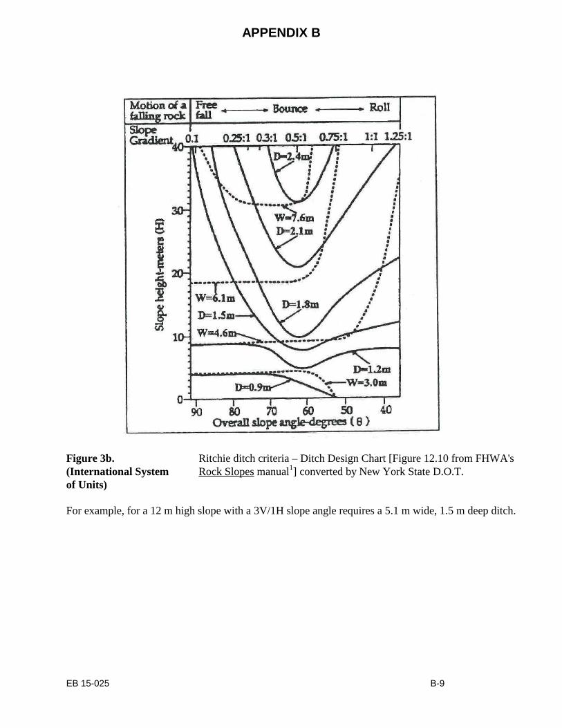
Ritchie Width and Ritchie Depth
First, determine slope height and overall slope angle. Based on those measurements, Ritchie
width and depth can be determined using the Ritchie design chart:
Figure 3a. Ritchie ditch criteria – Ditch Design Chart [Figure 12.10 from FHWA's
(US Customary Units) Rock Slopes manual1].
For example, for a 40 ft. high slope with a 3V/1H slope angle requires a ditch 17 ft. wide and 5 ft. deep
ditch.
APPENDIX B
EB 15-025 B-9
Figure 3b. Ritchie ditch criteria – Ditch Design Chart [Figure 12.10 from FHWA's
(International System Rock Slopes manual1] converted by New York State D.O.T.
of Units)
For example, for a 12 m high slope with a 3V/1H slope angle requires a 5.1 m wide, 1.5 m deep ditch.

APPENDIX B
EB 15-025 B-10
THE HUMAN EXPOSURE FACTOR (HEF)
Several field measurements are necessary to determine this factor.
Cut Length (L)
This is the measured length of the rock cut where a rockfall might occur that could reach the
pavement. It may be determined using a measuring wheel or measuring tape.
Decision Sight Distance (DSD)
This is the length of roadway where a 6 in. (150 mm) sight distance target located on the roadway
edge line first becomes visible to the approaching driver. Sight distance along a rock cut may
vary considerably, due to curves (horizontal) and rises (vertical) as well as trees, road signs, and
other objects. Referring to AASHTO standards3, a 6 in. (150 mm) sight distance target must be
placed along the roadway edge line, and sighted from the center of the lane at an eye height of 3
ft. (1 m). DSD is the measured distance to the point where the object disappears from sight, and
may be obtained using:
1. A 6 in. (150 mm) sight-distance target,
2. A 3 ft. (1 m) rod, and
3. A measuring wheel or measuring tape.
Target location may have to be adjusted and measurements taken at several points along the
slope before minimum distance can be determined. This length and any factors limiting sight
distance should be recorded. If sight distance is greater than 550 ft. (170 m) it need not be
measured, but should be recorded as "greater than 550 ft. (170 m)" on the field form.
Number of Lanes
Total travel lanes in one direction adjacent to the rock slope should be recorded, including
entrance ramps, exit ramps, and acceleration lanes, but not paved shoulders.
Stopping Sight Distance
The appropriate minimum adequate stopping sight distance can be determined from the
NYSDOT Highway Design Manual2.
APPENDIX B
EB 15-025 B-11
COMMON REMEDIAL TREATMENTS
The back of the site field evaluation sheet (Form GE 470 MET) lists typical rock slope problems
and possible remediation treatments. Before any remedial measures can be determined for the
rock slope, existing problems at the site must be understood. Mechanics of slope failure and
treatment are thoroughly analyzed in the FHWA Rock Slopes1.
Remedies
Some common rock slope remediation treatments are listed on the field sheet. Determine the
most appropriate treatment(s) based on sound engineering judgment. Sometimes a combination
of two or more treatments may be necessary. For example, a rock slope may require a recut and a
fence or barrier. A recut should be considered when a slope has a high SF or HEF. A scaling
contract for a slope having these characteristics will not reduce these factors, and the scaled slope
will still have a high relative risk. However, if a slope's high Total Relative Risk results mainly
from a high GF, it may be a good candidate for scaling. Recutting this slope may reduce its Total
Relative Risk little more than scaling. See Appendix C for guidelines on risk reduction.
After-Remediation Geologic Factors
The new GF can be estimated only after recommending treatment(s) for remediation. Based on
the character of the new remediated rock slope, a new GF can be determined using the rating
procedure. The new GF is the optimal GF that can be economically attained. For example,
recutting a slope might reduce its block size and rockfall-potential categories, but might not
affect the back slope above the cut.
Recutting
Once it has been decided that the appropriate remediation is to recut the slope, one must
determine the recut angle, recommended setback, and estimated quantity to be removed.
Recut Angle
This should be designed at the steepest possible angle that will result in a stable, maintenance-
free slope. A stable rock slope design may match the angle of major discontinuities or bedding
surfaces. Use a Brunton compass to measure orientation of bedding, foliation, fractures, and
joints. Consideration should be given to other factors that may affect the recut angle such as
right-of-way, required sight distance, or constructability.
Recommended Setback
The setback of the re-designed slope should conform to the currently accepted standard. The
plane of the new presplit slope should be located a minimum 5 ft. (1.5 m) behind the most
recessed part of the existing slope to provide sufficient burden for effective presplit blasting.
Scaling
Scaling quantities should be the estimated amount of rock (cubic meters) expected to be
removed, and not just the amount of loose rock on the slope. Removing a loose piece of rock
may undermine the slope, requiring that the upper part of the slope be scaled farther back. If
scaling with blasting is anticipated, this should be noted. Scaling volume can be roughly
estimated using the following formula:

APPENDIX B
EB 15-025 B-12
Surface area of existing rock cut face (ft2 (m
2)) x weathering depth (ft. (m))
For example (US Customary Units):
Given a rock slope surface area 20 ft. high and 500 ft. long, with an estimated 3 ft.
weathering depth (which is an appropriate weathering estimate for most rock slopes), the
following scaling quantity is estimated:
20 ft. x 500 ft. = 10,000 ft2 surface area
10,000 ft2 x 3 ft. = 30,000 ft
3 / 27 = 1111 yd
3 volume.
For example (International System of Units):
Given a rock slope surface area 6 m high and 152 m long, with an estimated 1 m
weathering depth (which is an appropriate weathering estimate for most rock slopes), the
following scaling quantity is estimated:
6 m x 152 m = 912 m2 surface area
912 m2 x 1 m = 912 m
3 volume.
Rock Bolting
This may be the sole treatment or may be used in combination with other remedial treatments.
Blocks of unstable rock must be large enough to be bolted, and the rock slope composed of
sufficiently competent rock to provide a suitable anchor. Rock bolts should be installed a
minimum of 3 ft. (1 m) past the weathered zone or discontinuity into competent rock.
Mesh
A rock mesh screen may be considered for entire slopes, or only for areas containing numerous
small (6 in. to 10 in. (150 to 250 mm) diameter) loose rocks, or where recutting or scaling is not
feasible or may create right-of-way problems.
Fence
Rock fence installation may be considered for the top of slope, on a rock bench, or at the toe of
slope. Design of optimal height and fence location can be aided by using the Colorado
Rockfall/Simulation Program (CRSP)5, Oregon DOT Rockfall Program
6, or other suitable
rockfall programs. Accurate cross-sections are necessary for reliable results.
Barrier System
This may be the sole treatment or may be used in combination with other remedial measures. Barrier
systems commonly considered are 1) an earth or broken-rock berm, 2) gabions, or 3) Jersey barrier or
barriers with fence.
Estimating Recut Quantity
The recut estimate section on the field sheet (Form GE 470 MET) is for estimating the quantity of rock
for the proposed slope recut, including the ditch section. This information can be used to determine rock
removal volumes via computer programs.

APPENDIX B
EB 15-025 B-13
Site Evaluation Field Sheet – US Customary Units

APPENDIX B
EB 15-025 B-14
Site Evaluation Field Sheet – US Customary Units

APPENDIX B
EB 15-025 B-15
Site Evaluation Field Sheet – International System of Units

APPENDIX B
EB 15-025 B-16
Site Evaluation Field Sheet – International System of Units

APPENDIX C
EB 15-025 C-1
GUIDELINES FOR DETERMINING RISK REDUCTION
Risk Reduction
It is assumed that "optimal" Risk Reduction may be achieved by 1) presplitting the rock slope at
a properly designed angle, and 2) providing catchment in accordance with the accepted
NYSDOT criteria. To determine "optimal" risk reduction, the section factor is set equal to 1,
which represents equality with the currently accepted criteria. Typical rock slope remediation
measures are presented here with a guideline for Risk Reduction.
Recut with Presplitting
Presplitting the rock slope usually results in greatest risk reduction. This is normally the preferred
treatment for a hazardous rock slope with limited offset. Presplitting may potentially reduce risk
values for all three factors -- GF, SF, and HEF. The GF may be reduced in the categories of
geology, block size, rockfall, and backslope above the cut. The SF changes to reflect the new
ditch dimensions of the "as-built" slope. Recutting the slope to meet currently accepted criteria
makes SF equal to 1. The HEF may be reduced if there was formerly a sight-distance problem.
Rock Bolting
Areas of the rock slope may be stabilized by rock bolting to reduce the quantity of unstable
material. Bolting may reduce the point values assigned to geology, block-size, rock-friction, and
rockfall categories of the GF.
Rock Scaling
Scaling may be recommended for specific blocks or locations, or for an entire slope. Scaling may
reduce the point values assigned to the GF categories: geology, block size, rockfall, and
backslope above cut.
Mesh
Mesh may be recommended for rock slope remediation where small (< 2 ft. (0.6 m) diameter)
blocks are raveling off the slope. Mesh may reduce point values in the GF categories of geology
(sedimentary or crystalline with sedimentary characteristics) and block size.
Rock Catchment Fence
Rock catchment fences may be used on a slope, at its top, or at its toe. Depending on location,
catchment fences may reduce the point values of GF category "backslope above cut" as well as
the Section Factor (SF).
Risk Reduction Table
Table 1 shows Geologic Factor category reductions corresponding to specific remediation
treatments.

APPENDIX C
EB 15-025 C-2
TABLE 1. RISK REDUCTION
TREATMENTS:
P = RECUT WITH PRESPLITTING (Other than to improve the Section Factor)
B = ROCK BOLTING
S = ROCK SCALING
M = MESH
F = FENCE OR BARRIER
CATEGORY 1A -
GEOLOGY
(Xtal.)
1 POINT
3 POINTS
9 POINTS
27 POINTS
81 POINTS
Massive, no
fractures dipping
out of slope.
Discontinuous
fractures, Random
orientation
Fractures that
form wedges
Discontinuous
fractures dipping
out of slope
Continuous fractures
dipping out of slope
TREATMENT
B, S
B, S
B, S
B, S
CATEGORY 1B -
GEOLOGY
(Sed.)
1 POINT
3 POINTS
9 POINTS
27 POINTS
81 POINTS
Horizontal to
slightly dipping.
Raveling, Occa-
sional small
blocks.
Small overhangs
or
columns, Numer-
ous small blocks.
Overhangs,
Some large un-
stable blocks,
High columns
Bedding or joints dip-
ping out of slope,
Over steepened cut
face
TREATMENT
P, S, M
P, B, S, M
P, B, S
P, B, S
CATEGORY 2 –
BLOCK SIZE
1 POINT
3 POINTS
9 POINTS
27 POINTS
81 POINTS
6 in. (150 mm)
6 in. to 12 in (150 mm to 300 mm)
1 ft. to 2 ft. (0.3 m to 0.6 m)
2 ft. to 5 ft. (0.6 m to 1.5 m)
5 ft. or more (1.5 m or more)
TREATMENT
P, S, M
P, B, S, M
P, B, S
P, B, S
CATEGORY 3 -
ROCK
FRICTION
1 POINT
3 POINTS
9 POINTS
27 POINTS
81 POINTS
Rough,
Irregular
Undulating
Planar
Smooth,
Slickensided
Clay, gouge-
faulted
TREATMENT
B
B
B

APPENDIX C
EB 15-025 C-3
CATEGORY 4 -
WATER/
ICE
1 POINT
3 POINTS
9 POINTS
27 POINTS
81 POINTS
Dry Some seepage
Moderate seep-
age
High
seepage/brush
High seepage with
long backslope/
brush
TREATMENT
No change
No change
No change
No change
CATEGORY 5 -
ROCK
FALL
1 POINT
3 POINTS
9 POINTS
27 POINTS
81 POINTS
No Falls Occasional
minor falls
Occasional falls
Regular falls
Major falls/ slides
TREATMENT
P, B, S, F
P, B, S, F
P, B, S,F
P, B, S, F
CATEGORY 6 -
BACKSLOPE
ABOVE CUT
1 POINT
3 POINTS
9 POINTS
27 POINTS
81 POINTS
Flat to gentle
slope
(up to 15)
Moderate slope
(15-25)
Steep slope
(25 - 35)
Very steep (>35)
or steep (25-35)
with boulders
Very steep (>35)
slope with boulders
TREATMENT
P, F
P, F, S
P, F, S
P, F, S


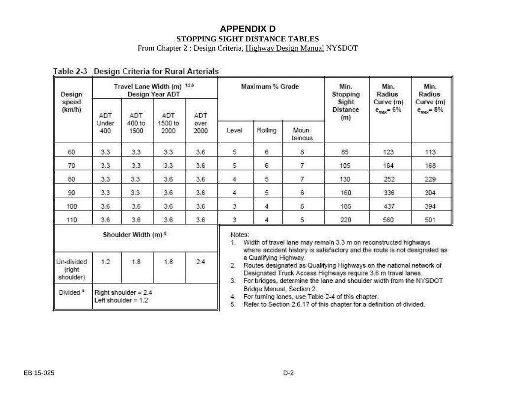
APPENDIX D STOPPING SIGHT DISTANCE TABLES
From Chapter 2 : Design Criteria, Highway Design Manual NYSDOT
EB 15-025 D-1
APPENDIX D STOPPING SIGHT DISTANCE TABLES
From Chapter 2 : Design Criteria, Highway Design Manual NYSDOT
EB 15-025 D-2

APPENDIX D STOPPING SIGHT DISTANCE TABLES
From Chapter 2 : Design Criteria, Highway Design Manual NYSDOT
EB 15-025 D-3

APPENDIX D STOPPING SIGHT DISTANCE TABLES
From Chapter 2 : Design Criteria, Highway Design Manual NYSDOT
EB 15-025 D-4

APPENDIX D STOPPING SIGHT DISTANCE TABLES
From Chapter 2 : Design Criteria, Highway Design Manual NYSDOT
EB 15-025 D-5

APPENDIX D STOPPING SIGHT DISTANCE TABLES
From Chapter 2 : Design Criteria, Highway Design Manual NYSDOT
EB 15-025 D-6

APPENDIX D STOPPING SIGHT DISTANCE TABLES
From Chapter 2 : Design Criteria, Highway Design Manual NYSDOT
EB 15-025 D-7