Embed Size (px)
Citation preview
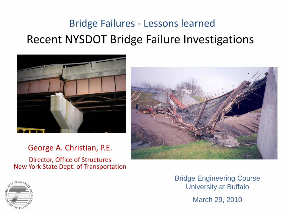
Bridge Failures - Lessons learned
Recent NYSDOT Bridge Failure Investigations
George A. Christian, P.E.
Director, Office of StructuresNew York State Dept. of Transportation
Bridge Engineering Course
University at Buffalo
March 29, 2010

2
I-787 - Dunn Memorial Bridge InterchangeAlbany, NY
partial collapse at pier 11- August 2005
I-787 Ramp NB to South Mall
Expressway WB
(BIN 109299A)

3
BIN 109299A

4
Structure Layout (looking east)

5
Overview of Failure
6
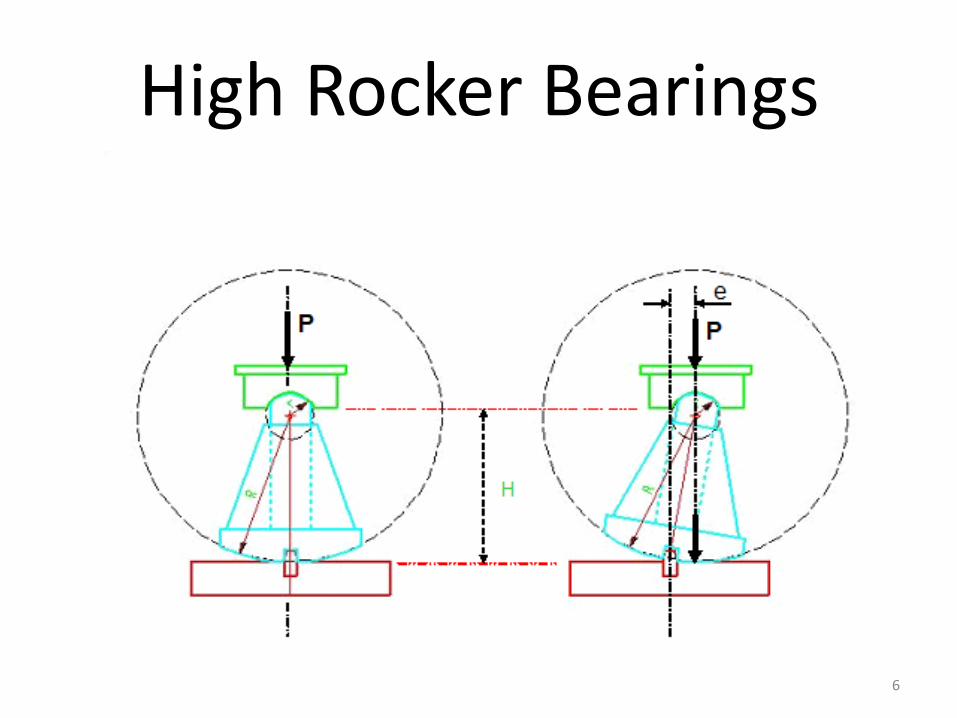
High Rocker Bearings

7
History of Misalignment of High Rocker Bearings at Pier 11
1987 Inspection
Temp. @ 45 °F
1999 Inspection
Temp. @ 70 °F
8
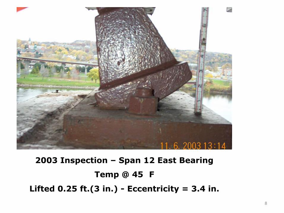
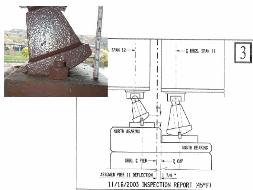
2003 Inspection – Span 12 East Bearing
Temp @ 45 F
Lifted 0.25 ft.(3 in.) - Eccentricity = 3.4 in.

9
How did the bearings get misaligned?
Superstructure Displacements:• Survey of adjacent piers (w/ fixed bearings)
– Pier 10 displaced north 1.6 inches.
– Pier 12 displaced north 1.0 in (avg.) 1.7 inches on east side.
• History of Pier 13 joint
– Joints ‘reset’ (vertical) in 1990
– Joint was closed in 1990
– Closed in 1995 thru present
• Longitudinal forces due to braking, centrifugal force

10
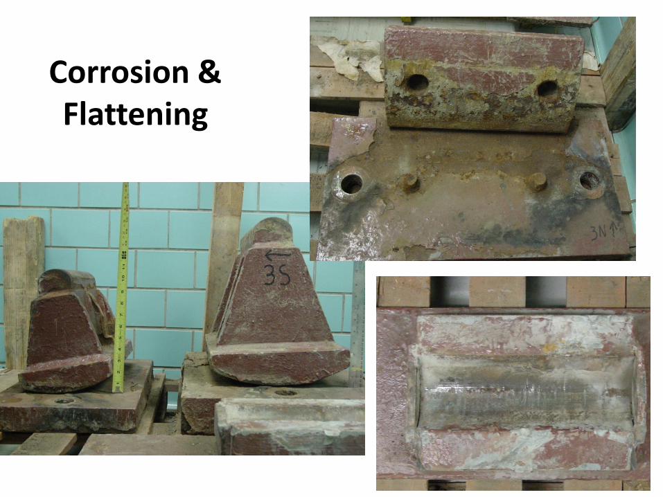
Condition of Rocker Bearings• Susceptible to corrosion, debris when continually
tilted
• Corrosion, debris prevents rocking back toward vertical
– Under rocker
– Pin corrosion
• Contact surfaces flatten or “dish”
• Result: Bearings become resistant to horizontal movement, especially back toward being plumb . Transfers longitudinal forces to substructure
11
Corrosion & Flattening

12
Frozen Pins
13
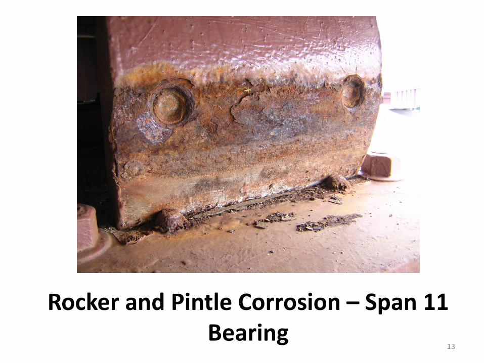
Rocker and Pintle Corrosion – Span 11 Bearing
14
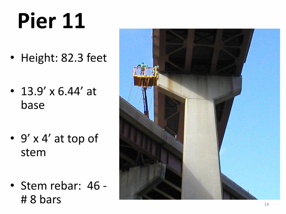
Pier 11
• Height: 82.3 feet
• 13.9’ x 6.44’ at base
• 9’ x 4’ at top of stem
• Stem rebar: 46 -# 8 bars

15
Pier 11: Lack of Elastic Range
• Cracks 40 ft. up north face
• Rebounded 51/2 in. when ‘released’
• The pier failed in flexure
16
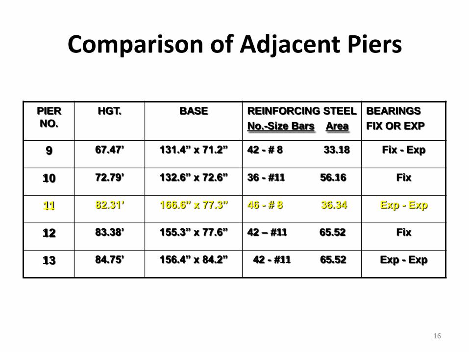
Comparison of Adjacent Piers
PIER
NO.
HGT. BASE REINFORCING STEEL
No.-Size Bars Area
BEARINGS
FIX OR EXP
9 67.47’ 131.4” x 71.2” 42 - # 8 33.18 Fix - Exp
10 72.79’ 132.6” x 72.6” 36 - #11 56.16 Fix
11 82.31’ 166.6” x 77.3” 46 - # 8 36.34 Exp - Exp
12 83.38’ 155.3” x 77.6” 42 – #11 65.52 Fix
13 84.75’ 156.4” x 84.2” 42 - #11 65.52 Exp - Exp

17
Pier 11 Design Check
• Designed per 1965 AASHO code
• Meets strength req. for code assumptions
– Allowable / Actual ratio = 0.98 =1.0 (OK)
• No provision for large flexural displacements
• Equivalent Column with 1% reinforcing.
18
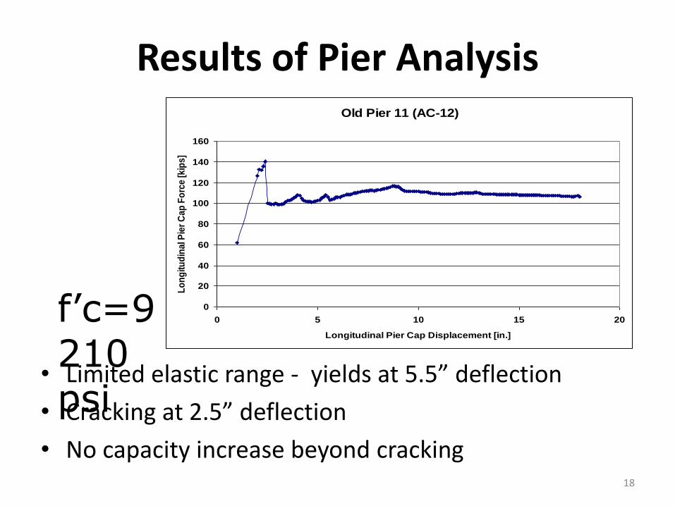
Results of Pier Analysis
• Limited elastic range - yields at 5.5” deflection
• Cracking at 2.5” deflection
• No capacity increase beyond cracking
Old Pier 11 (AC-12)
0
20
40
60
80
100
120
140
160
0 5 10 15 20
Longitudinal Pier Cap Displacement [in.]
Lo
ng
itu
din
al P
ier
Ca
p F
orc
e [
kip
s]
f’c=9210 psi

19
Forces Needed for Failure
• Thermal: limited by resistance of bearing
– Up to 0.58 x Dead Load if sliding assumed: approx. 200 kip from Span 12 only
– Limited range of movement
• Corrosion Build-up:
– Develops horizontal component of vertical dead, live load reactions
– Larger range of movement
20
Probable Failure Sequence
• Bearings tilted to north > 20 years ago
• Bearings begin to resist horizontal mov’t.
• Superstructure longitudinal displacements began to move pier instead of Span 12 bearings
• Bearings resist movement moving back toward vertical– Increased southward tipping of Span 12 and 11 bearings
• Instability point reached – bearings tipped
• Forces (displacements) sustained to deflect pier 16 + in. (bearings tipping and spans falling on tipped bearings)

21
22

23
24

25

26

27

28

29

30

31
32

33
Underlying Cause of Failure
1. Rocker bearings becoming misaligned
2. Rocker bearing not functioning properly
3. Pier 11 was flexible in direction longitudinal to the bridge
4. Pier 11 stem was “lightly” reinforced, and not elastically ductile
• 1, 2 and 3 were required for failure to occur. 4 may have been required, but contributed to extent of failure

34

35

36
Follow up actions
• Reviewed all high rocker bearings with low inspection ratings (CR 3 or less)
• Inspected those overextended
• Preventive interim retrofits – bolsters
• Technical Advisory: INSP 05-001

37
Follow up actions
• Bolsters installed as an extraordinary precautionary measures on 10 bridges
• Alerted other owners of bridges not under DOT’s inspection jurisdiction
• Corrective action:– Dunn Complex, bearing replacements
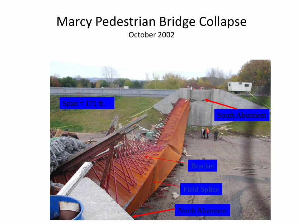
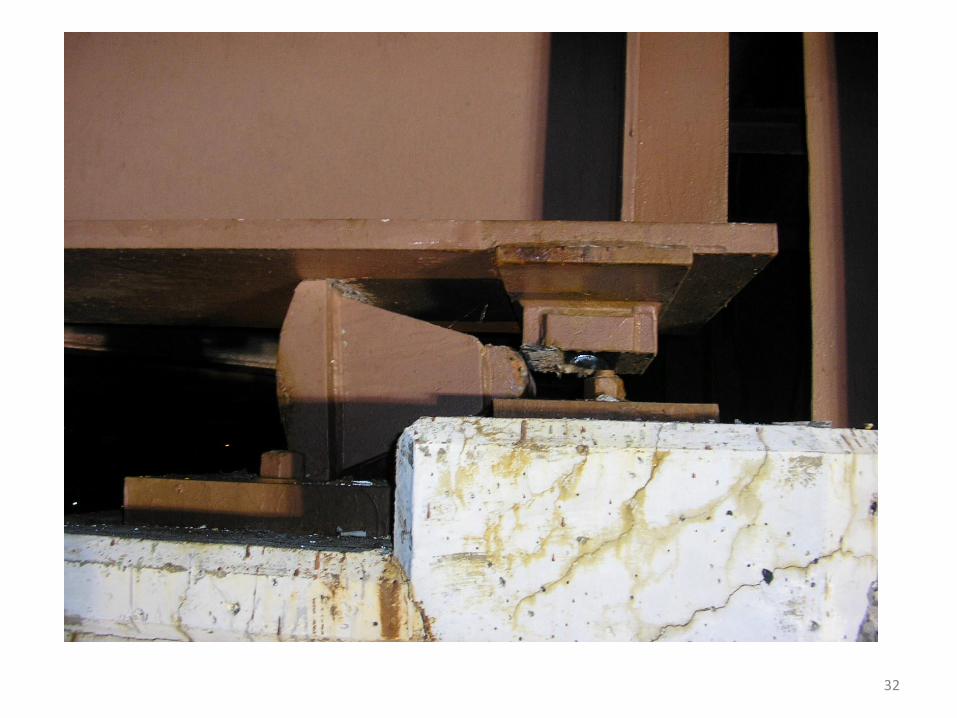
Marcy Pedestrian Bridge CollapseOctober 2002
South Abutment
North Abutment
Bracket
Field Splice
Span = 171 ft.

Acknowledgements
• Sponsored by New York State DOT
• P.I.—Weidlinger Associates, Inc.
• Material testing and weld inspections by ATLSS Research Engineering Center, Lehigh University
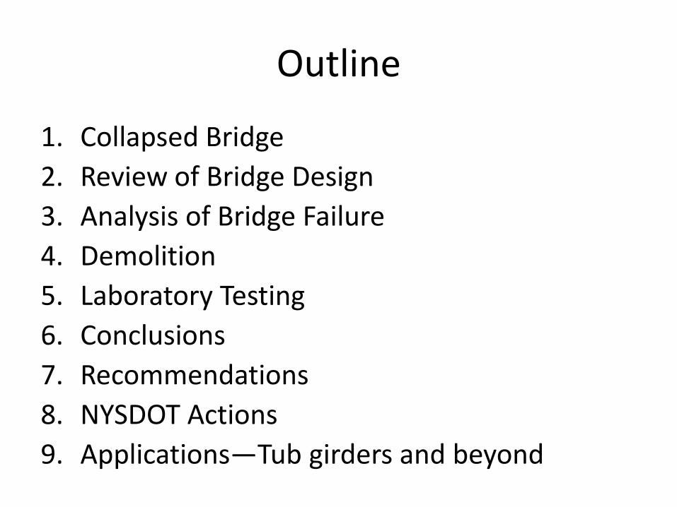
Outline
1. Collapsed Bridge
2. Review of Bridge Design
3. Analysis of Bridge Failure
4. Demolition
5. Laboratory Testing
6. Conclusions
7. Recommendations
8. NYSDOT Actions
9. Applications—Tub girders and beyond

Tub Girder Cross Section
Intermediate
Diaphragm
14.0 ft (4.27 m)
6.3
ft
(1.9
3 m
)
4.3 ft (1.3 m)

Collapsed Bridge
North Abutment
South Abutment
Screed
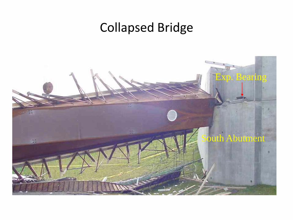
Collapsed Bridge
South Abutment
Exp. Bearing

Collapsed Bridge
North AbutmentFixed Bearing
2. Review of Bridge Design
Objective: Evaluate the adequacy of the bridge design
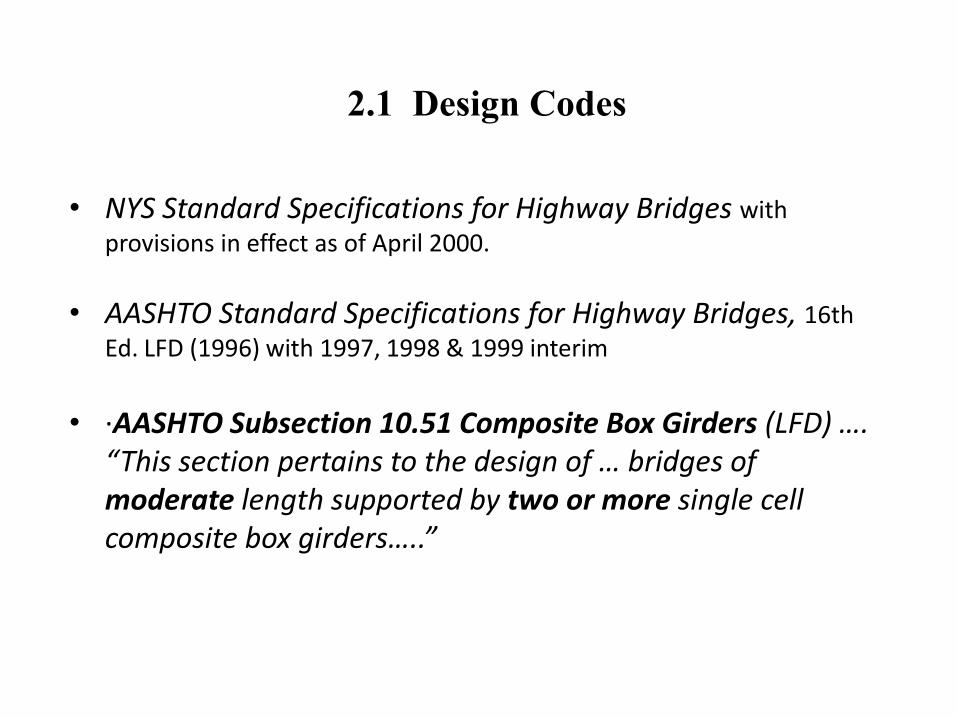
2.1 Design Codes
• NYS Standard Specifications for Highway Bridges with
provisions in effect as of April 2000.
• AASHTO Standard Specifications for Highway Bridges, 16th
Ed. LFD (1996) with 1997, 1998 & 1999 interim
• ·AASHTO Subsection 10.51 Composite Box Girders (LFD) …. “This section pertains to the design of … bridges of moderate length supported by two or more single cell composite box girders…..”
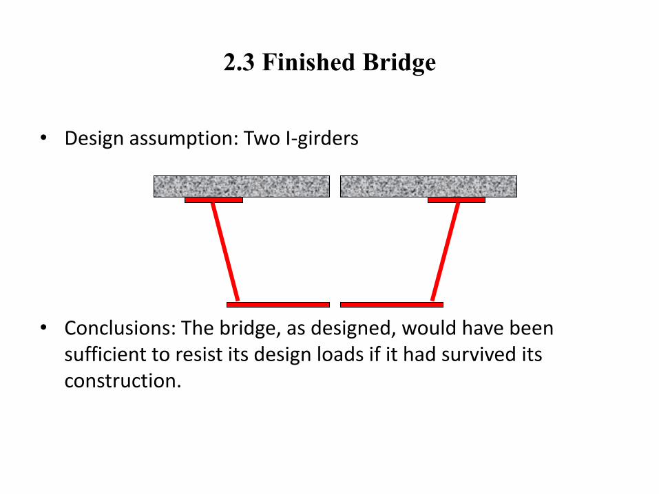
2.3 Finished Bridge
• Design assumption: Two I-girders
• Conclusions: The bridge, as designed, would have been sufficient to resist its design loads if it had survived its construction.
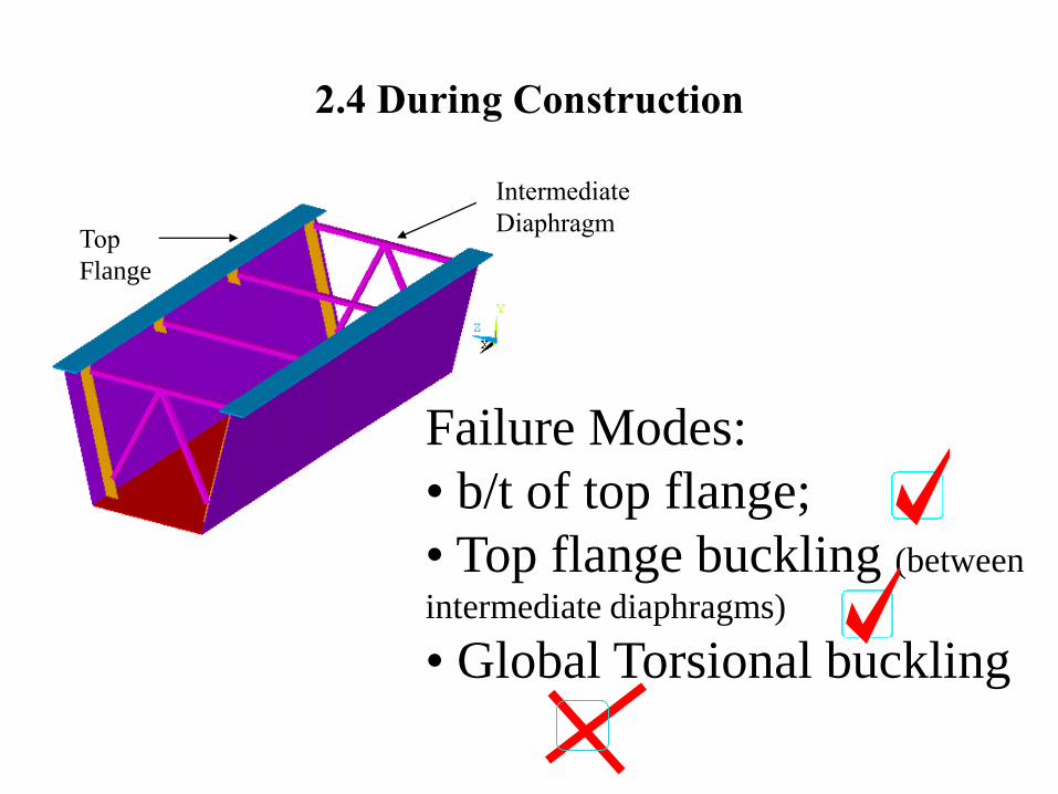
2.4 During Construction
Failure Modes:
• b/t of top flange;
• Top flange buckling (between
intermediate diaphragms)
• Global Torsional buckling
Intermediate
DiaphragmTop
Flange
3. Analysis of Bridge Failure
Objective: To find and prove the cause of failure
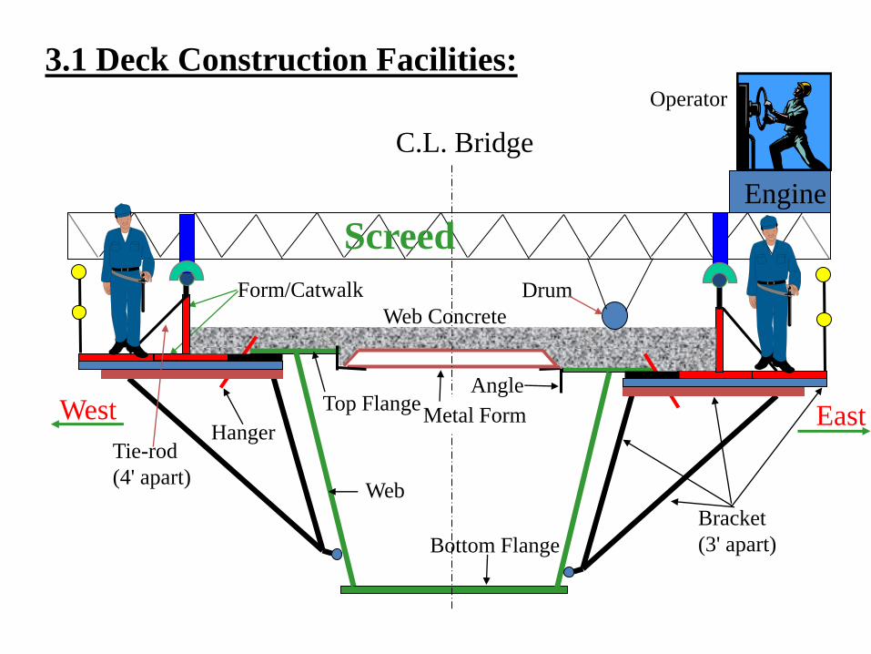
Metal Form
Angle
Bottom Flange
Bracket
(3' apart)
Form/Catwalk
Tie-rod
(4' apart)
Web Concrete
Top Flange
Web
HangerWest
Operator
Drum
C.L. Bridge
Engine
Screed
East
3.1 Deck Construction Facilities:
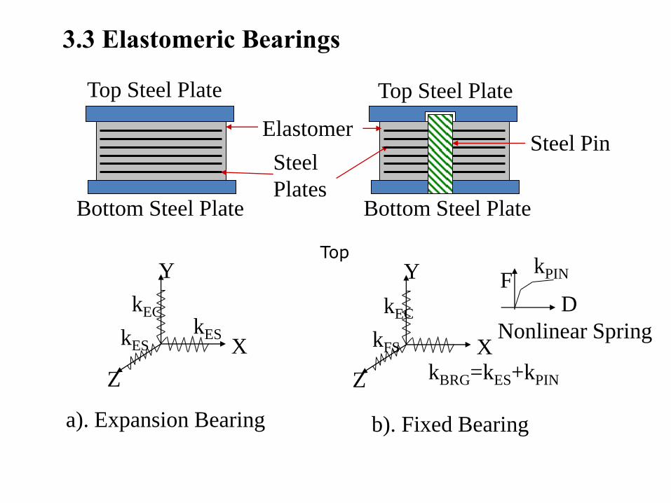
Top
Top Steel Plate
Bottom Steel Plate
Elastomer
Steel
Plates
a). Expansion Bearing
Top Steel Plate
Bottom Steel Plate
b). Fixed Bearing
Steel Pin
kESkES
kEC
X
Y
Z kBRG=kES+kPIN
kFS
kEC
X
Y
Z
FD
Nonlinear Spring
kPIN
3.3 Elastomeric Bearings
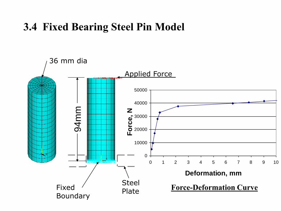
0
10000
20000
30000
40000
50000
0 1 2 3 4 5 6 7 8 9 10
Deformation, mm
Fo
rce
, N
36 mm dia
Applied Force
SteelPlate
Force-Deformation CurveFixedBoundary
94m
m
3.4 Fixed Bearing Steel Pin Model

End
Diaphragm
Top Flange
Top Flange
Web
Diaphragm
Strut
3.5 Global Model
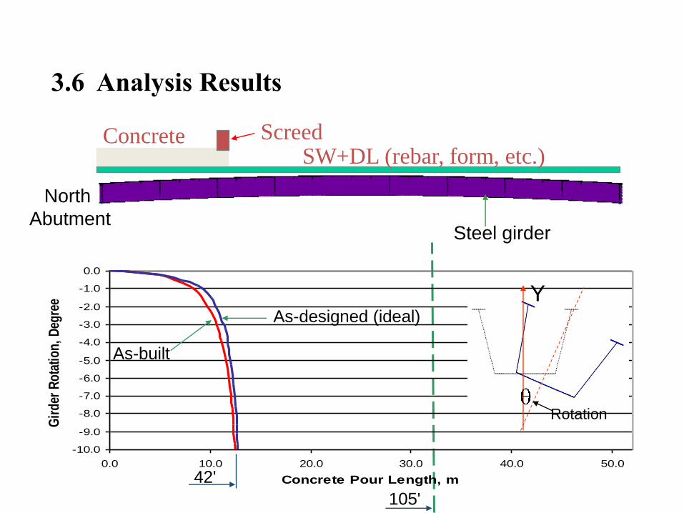
SW+DL (rebar, form, etc.)Concrete Screed
Steel girder
North
Abutment
-10.0
-9.0
-8.0
-7.0
-6.0
-5.0
-4.0
-3.0
-2.0
-1.0
0.0
0.0 10.0 20.0 30.0 40.0 50.0
Concrete Pour Length, m
Gir
der
Ro
tati
on
, D
egre
e
As-built
As-designed (ideal)
Y
Rotation
42'
105'
3.6 Analysis Results
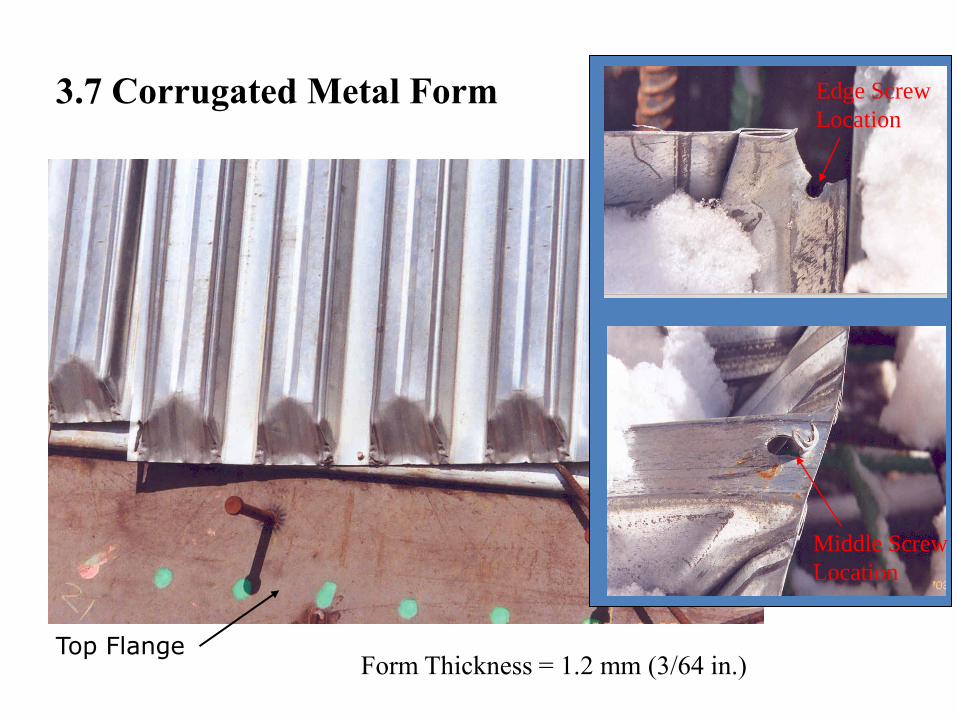
Middle Screw
Location
Edge Screw
Location3.7 Corrugated Metal Form
Form Thickness = 1.2 mm (3/64 in.)Top Flange

F
Fixed Boundarya
Weak Form: a=1/2" (12 mm)Fy = 40 ksi (275 MPa)
Strong Form: a=3/4" (20 mm)Fy = 45 ksi (310 MPa)
3.9 Form Connection Model

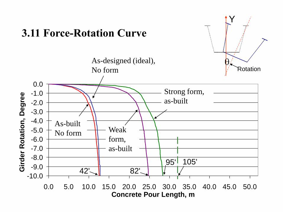
-10.0
-9.0
-8.0
-7.0
-6.0
-5.0
-4.0
-3.0
-2.0
-1.0
0.0
0.0 5.0 10.0 15.0 20.0 25.0 30.0 35.0 40.0 45.0 50.0Concrete Pour Length, m
Gir
de
r R
ota
tio
n,
De
gre
e
As-designed (ideal),
No form
As-built
No form
Strong form,
as-built
Weak
form,
as-built
42' 82'95' 105'
Y
Rotation
3.11 Force-Rotation Curve
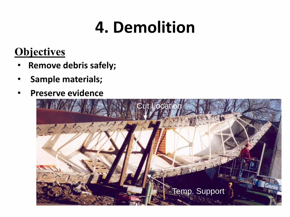
4. Demolition
• Remove debris safely;
• Sample materials;
• Preserve evidence
Temp. Support
Cut Location
Objectives

5. Laboratory Testing
• Verify Analysis Assumptions
• Check whether materials conform to contract specifications
Objectives:

0
2000
4000
6000
8000
10000
12000
0 2.5 5 7.5 10 12.5 15 17.5 20 22.5 25
Lateral Deformation, mm
Fo
rce, N
Force-Deformation Curve
of Form Connections
Strong Form Model
Weak Form Model
Lab Results
5.1 Form Connection Tests
Form connection test
Gage 12
Steel PL
Form
Screw
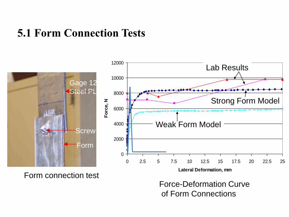
0
2000
4000
6000
8000
10000
12000
0 2.5 5 7.5 10 12.5 15 17.5 20 22.5 25
Lateral Deformation, mm
Fo
rce, N
Force-Deformation Curve
of Form Connections
Strong Form Model
Weak Form Model
Lab Results
5.1 Form Connection Tests
Form connection test
Gage 12
Steel PL
Form
Screw

b. Bearing Model
Fixed Boundary
a. Damaged Fixed Bearing
5.2 Bearing Inspection

6. Conclusions
• The bridge failed in a global torsional mode;
• Stay-in-place forms greatly delayed the collapse, but were not strong enough to prevent it;
• Progressive failure of form connections that initiated the failure sequence
• The bridge would have buckled even if the two deck haunches were identical

7. Recommendations
• Clarify applicable codes;
• Add a new code provision that requires full length lateral bracing to be installed between top flanges unless proven unnecessary by analysis
8. NYSDOT Actions
• Reviewed similar ongoing projects in NYS.
• Required bracing systems for similar bridges in NYS—(NYSDOT “Blue Page”)
• Sought recommendations from AASHTO regarding code revisions.
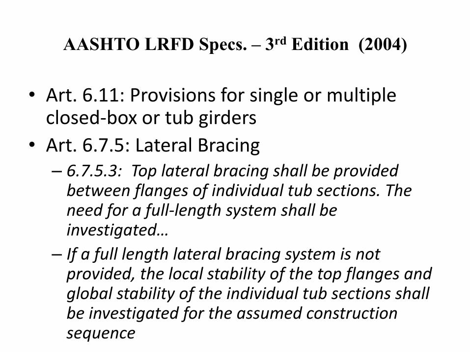
AASHTO LRFD Specs. – 3rd Edition (2004)
• Art. 6.11: Provisions for single or multiple closed-box or tub girders
• Art. 6.7.5: Lateral Bracing– 6.7.5.3: Top lateral bracing shall be provided
between flanges of individual tub sections. The need for a full-length system shall be investigated…
– If a full length lateral bracing system is not provided, the local stability of the top flanges and global stability of the individual tub sections shall be investigated for the assumed construction sequence

Centroid @ +36.3”Shear Ctr. @ -36.0”Izz = 36 in^4Iyy = 205,817 in^4
Centroid @ +37.3”Shear Ctr. @ -12.2”Izz = 114,870 in^4Iyy = 212,572 in^4
1/16” Top Plate
Lateral Torsional Stability of Open-tub girders

Application to I-Girder Bridges
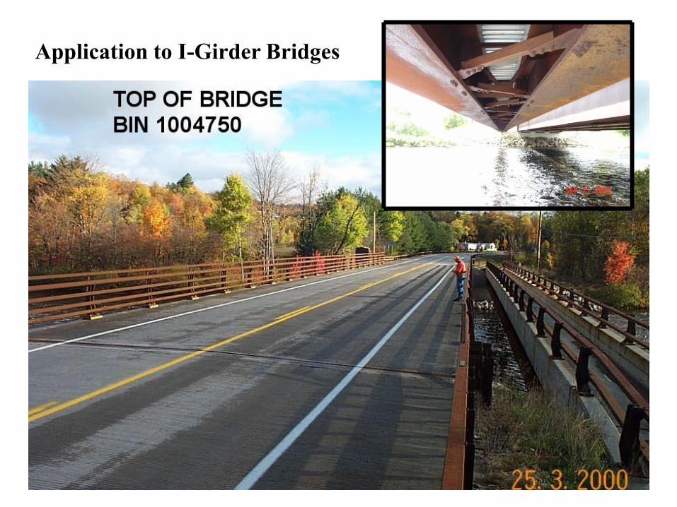
Application to I-Girder Bridges
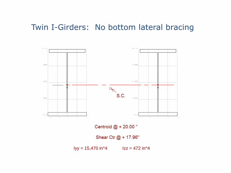
Twin I-Girders: No bottom lateral bracing
Iyy = 15,470 in^4 Izz = 472 in^4
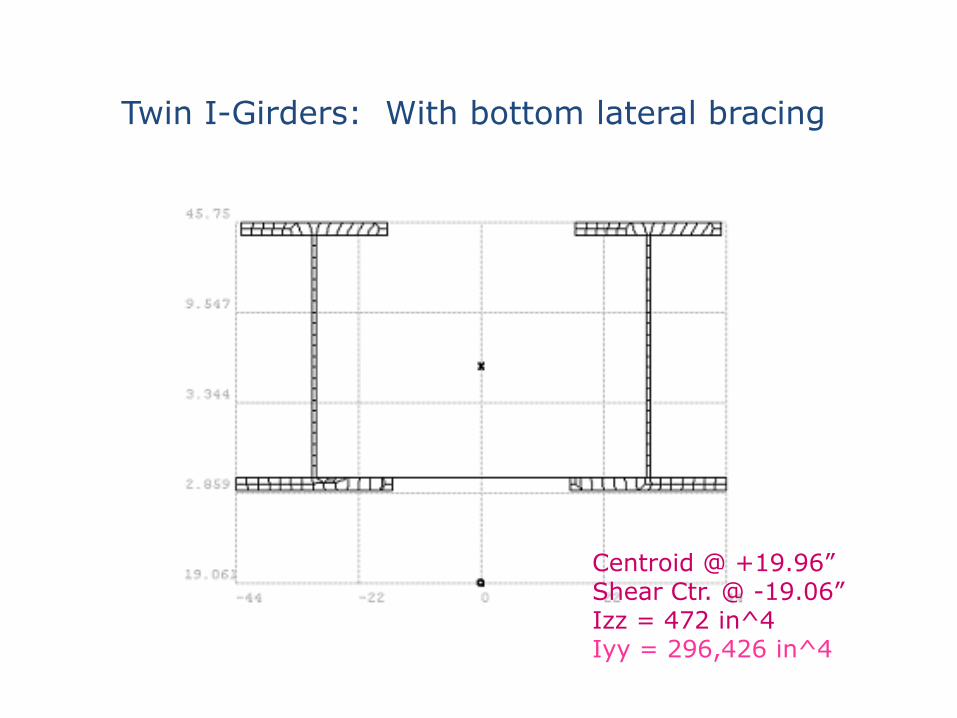
Centroid @ +19.96”Shear Ctr. @ -19.06”Izz = 472 in^4Iyy = 296,426 in^4
Twin I-Girders: With bottom lateral bracing

LTB with Non-linear Plate Model
0.0
0.5
1.0
1.5
2.0
2.5
0.0 20.0 40.0 60.0 80.0
Transverse Displacement at Midspan [in.]
De
ad
Lo
ad
Fa
cto
rTwin I-Girders: With bottom lateral bracing
6
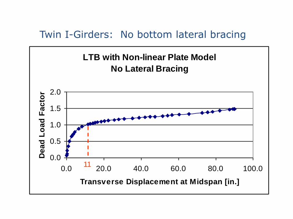
LTB with Non-linear Plate Model
No Lateral Bracing
0.0
0.5
1.0
1.5
2.0
0.0 20.0 40.0 60.0 80.0 100.0
Transverse Displacement at Midspan [in.]
De
ad
Lo
ad
Fa
cto
r
11
Twin I-Girders: No bottom lateral bracing
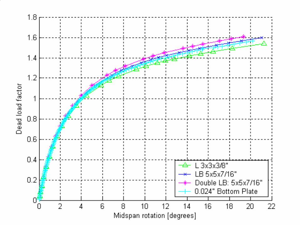


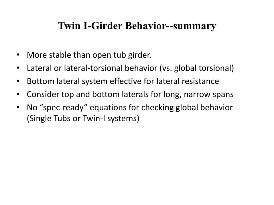
Twin I-Girder Behavior--summary
• More stable than open tub girder.
• Lateral or lateral-torsional behavior (vs. global torsional)
• Bottom lateral system effective for lateral resistance
• Consider top and bottom laterals for long, narrow spans
• No “spec-ready” equations for checking global behavior (Single Tubs or Twin-I systems)
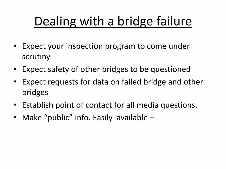
Dealing with a bridge failure
• Expect your inspection program to come under scrutiny
• Expect safety of other bridges to be questioned
• Expect requests for data on failed bridge and other bridges
• Establish point of contact for all media questions.
• Make “public” info. Easily available –
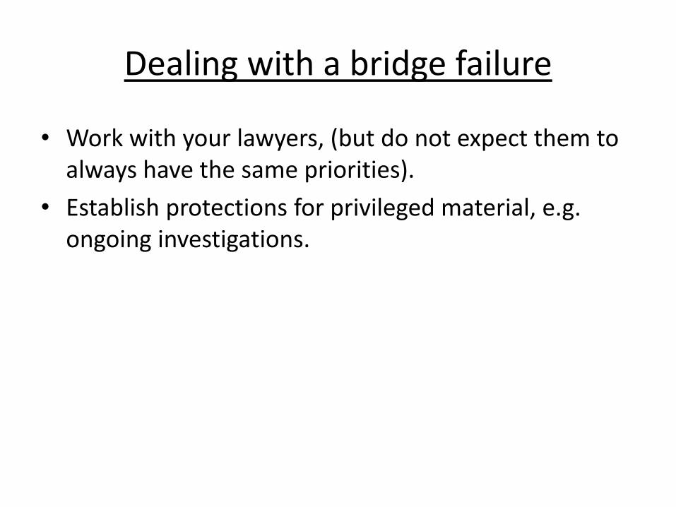
Dealing with a bridge failure
• Work with your lawyers, (but do not expect them to always have the same priorities).
• Establish protections for privileged material, e.g. ongoing investigations.

The Paradox of Failure
“When it comes to bridge
design, collapse is a most
reliable teacher.”
Henry Petroski
“Success Through Failure; The
Paradox of Design”
One Final Lesson

Questions?