Embed Size (px)
Citation preview
ROBUST PROJECT
CIDAUT WP5 - Computational Mechanics B1 Barrier – Steel N2 MAIN REPORT Volume 1 of 1
November 2005 Doc. No.: ROBUST-5-015 – Rev 0
Main Report
286-2-1-no-en
Report title:
WP5 - Computational Mechanics B5 Concrete Barrier
Client:
CIDAUT
Doc. no.:
ROBUST-5-015
Project no.:
202.813023 / ROBUST-GRD1-2002-70021
Reporter(s):
J García
Abstract:
The Robust Project aims to improve scientific and technical knowledge on the main issues still open in the new European standards on the road restraint system EN1317. The knowledge acquired will form the basis of updated standards for EN 1317 and lead to more advanced road restraint systems and improve road-users safety. This report is part of the deliverables from Work Package 5 – Computational Mechanics. This report documents the simulations performed on the B2 steel barrier. The simulations were performed by CIDAUT.
Keywords:
Restricted
Internal
Free distribution
Ref. allowed
Rev. no. Date Prepared by Checked by Approved by Reason for revision
0 22/5/6 J Garcia Public release
ROBUST project Page i
CIDAUT ROBUST-5-015 – Rev 0
WP5 - Computational Mechanics B1 Steel Barrier MAIN REPORT
CONTENTS
1 INTRODUCTION..................................................................................................1
2 SUMMARY AND CONCLUSIONS .......................................................................2 2.1 Summary..............................................................................................................2 2.2 Conclusions .........................................................................................................2
3 BARRIER – B1 VS GEOMETRO. FULL LENGTH................................................3 3.1 General ................................................................................................................3 3.2 Additional data .....................................................................................................3 3.3 Input data.............................................................................................................4 3.3.1 Test item ..............................................................................................................4 3.3.2 Test procedure.....................................................................................................4 3.3.3 Analysis data........................................................................................................4 3.4 Analysis results ....................................................................................................7
4 BARRIER – B1 VS GEOMETRO. REDUCED LENGTH.....................................14 4.1 General ..............................................................................................................14 4.2 Additional data ...................................................................................................14 4.3 Input data...........................................................................................................14 4.3.1 Test item ............................................................................................................14 4.3.2 Test procedure...................................................................................................15 4.3.3 Analysis data......................................................................................................15 4.4 Analysis results ..................................................................................................18
5 BARRIER – B1. REDUCED MODELS (SIGMA POSTS)....................................25 5.1 General ..............................................................................................................25 5.2 Additional data ...................................................................................................25 5.3 Input data...........................................................................................................25 5.3.1 Test item ............................................................................................................25 5.3.2 Test procedure...................................................................................................25 5.4 Analysis results ..................................................................................................27
6 REFERENCES...................................................................................................30
ROBUST project Page 1
CIDAUT ROBUST-5-015 – Rev 0
WP5 - Computational Mechanics B1 Steel Barrier MAIN REPORT
1 INTRODUCTION
Within ROBUST project WP5, CIDAUT carried out simulations of a vehicle, impacting a steel barrier. The impact conditions were according to EN1317 – Part 2 specifications for TB11 crash test, with an initial speed of 100 km/h and an angle of 20 degrees. The vehicle used for the test simulations was a version of the Geometro model specifically adapted for PAM-CRASH simulation code. The objectives of the WP5 project are:
• Evaluation and enhancement of the use of computational mechanics to complement experimental activity
• Criteria and procedures for the validation of computational mechanics results through comparison with test results
• Reconstruction of real life accidents
• Identification of activity needed for further enhancement of the use of computational mechanics
The simulations reported are focused on the first objective. The work included variety of simulations considering different parameters: material, length, bolt modelling, etc. Also reduced simulations were peformed. This report documents the simulations performed on the B1 steel safety barrier.
ROBUST project Page 2
CIDAUT ROBUST-5-015 – Rev 0
WP5 - Computational Mechanics B1 Steel Barrier MAIN REPORT
2 SUMMARY AND CONCLUSIONS
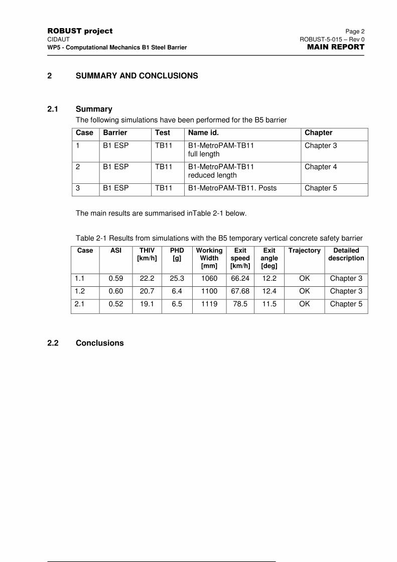
2.1 Summary
The following simulations have been performed for the B5 barrier
Case Barrier Test Name id. Chapter
1 B1 ESP TB11 B1-MetroPAM-TB11 full length
Chapter 3
2 B1 ESP TB11 B1-MetroPAM-TB11 reduced length
Chapter 4
3 B1 ESP TB11 B1-MetroPAM-TB11. Posts Chapter 5
The main results are summarised inTable 2-1 below.
Table 2-1 Results from simulations with the B5 temporary vertical concrete safety barrier
Case ASI THIV [km/h]
PHD [g]
Working Width [mm]
Exit speed [km/h]
Exit angle [deg]
Trajectory Detailed description
1.1 0.59 22.2 25.3 1060 66.24 12.2 OK Chapter 3
1.2 0.60 20.7 6.4 1100 67.68 12.4 OK Chapter 3
2.1 0.52 19.1 6.5 1119 78.5 11.5 OK Chapter 5
2.2 Conclusions
ROBUST project Page 3
CIDAUT ROBUST-5-015 – Rev 0
WP5 - Computational Mechanics B1 Steel Barrier MAIN REPORT
3 BARRIER – B1 VS GEOMETRO. FULL LENGTH
3.1 General
The barrier used in the simulation represented the B1 barrier (ESP steel barrier, N2). The vehicle model was a light passenger vehicle, developed by CIDAUT for simulation with the PAM-CRASHTM code. This vehicle model has the same overall geometry as the Geometro model which was supplied as part of the project, and complies with the vehicle characteristics specified by EN1317 for 900-kg vehicle.
The simulation scenario consisted of the vehicle impacting the barrier with an initial speed of 100 km/h and an angle of 20 degrees.
The characteristics specific to this simulation are:
� The barrier was modelled using a non-linear material model and represented by shell elements for all steel pieces that reproduced its geometry.
� The full length of the barrier was modelled.
� Post embedment in soil was modelled by fixing posts 200 below ground level.
� Friction between the vehicle and the barrier was set to 0.
� Friction between the ground and the tyres was set to 0.6
3.2 Additional data
The following data and files supplement the result presentation of the simulation as presented in this chapter.
Excel worksheet file:
Rawdata file: B1-metroPAM-c1.zip
Animations:
- front view B1-c1_front.avi
- side view B1-c1_side.avi
- top view B1-c1_top.avi
-perspective B1-c1_iso.avi
ROBUST project Page 4
CIDAUT ROBUST-5-015 – Rev 0
WP5 - Computational Mechanics B1 Steel Barrier MAIN REPORT
3.3 Input data
3.3.1 Test item
Test item: ESP – N2
Vehicle: Geometro - PAMCRASH
3.3.2 Test procedure
1) Test type – TB11
Impact speed: 103.5 km/h
Impact angle: 20 degrees
Impact point: About 26 metres from the beginning of the VRS
Spinning wheels: No
Inertial vehicle test mass: 904 kg
2) VRS model
Barrier type: ESP – N2
Number of posts: 39
Spacing: 2 m
Total length: 76 m
Element formulation/type: Shell elements.
Connection/Joints: Tied joints with failure
Foundation: Posts fixed to the soil
End anchoring: None
Soil (type and formulation): Posts fixed to the soil
Roadway: Modelled as rigid wall
3) Vehicle model
Light passenger vehicle, developed by CIDAUT for simulation with PAM-CRASHTM.
3.3.3 Analysis data
Timestep: Between 2 and 3 E-06
Precision: Single
ROBUST project Page 5
CIDAUT ROBUST-5-015 – Rev 0
WP5 - Computational Mechanics B1 Steel Barrier MAIN REPORT
Friction barrier/vehicle (static coefficient): 0
Friction barrier/vehicle (dynamic coefficient) 0
Friction wheel/ground (static coefficient) 0.6
Friction wheel/ground (dynamic coefficient) 0.6
Accelerometer location (mounting block) Coincident with vehicle cog: Distance 16 mm in Y-direction, less than 1 mm in X and Z directions.
Sampling rate
Friction other:
1.0 E-4 for THP
NA
ROBUST project Page 6
CIDAUT ROBUST-5-015 – Rev 0
WP5 - Computational Mechanics B1 Steel Barrier MAIN REPORT
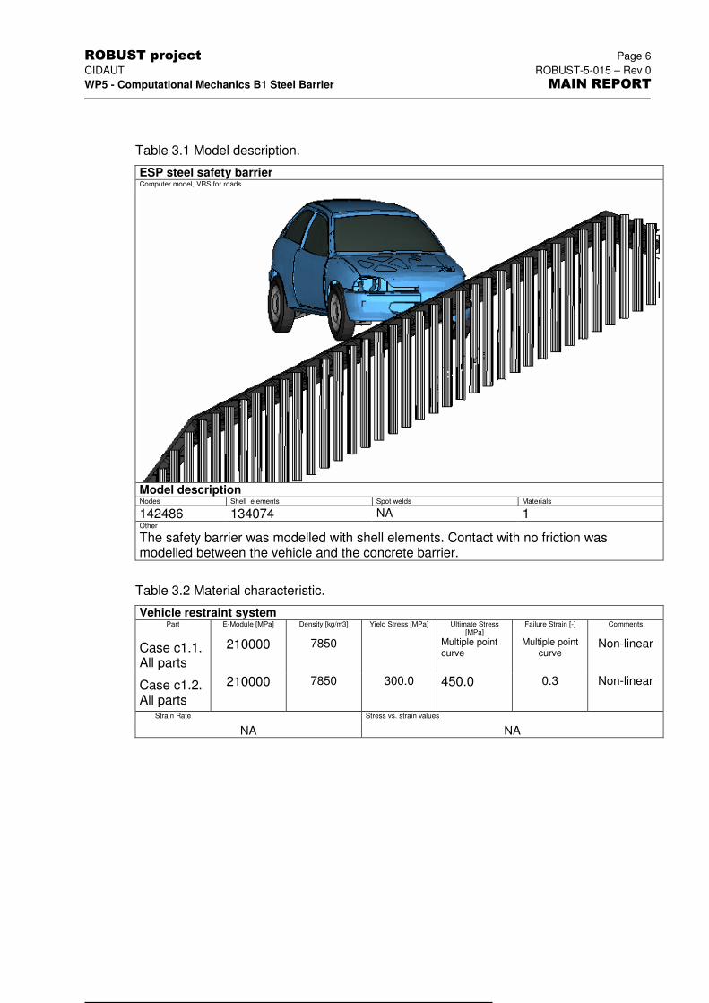
Table 3.1 Model description.
ESP steel safety barrier Computer model, VRS for roads
Model description Nodes Shell elements Spot welds Materials
142486 134074 NA 1 Other
The safety barrier was modelled with shell elements. Contact with no friction was modelled between the vehicle and the concrete barrier.
Table 3.2 Material characteristic.
Vehicle restraint system Part E-Module [MPa] Density [kg/m3] Yield Stress [MPa] Ultimate Stress
[MPa] Failure Strain [-] Comments
Case c1.1. All parts
210000 7850 Multiple point curve
Multiple point curve
Non-linear
Case c1.2. All parts
210000 7850 300.0 450.0 0.3 Non-linear
Strain Rate Stress vs. strain values
NA NA
ROBUST project Page 7
CIDAUT ROBUST-5-015 – Rev 0
WP5 - Computational Mechanics B1 Steel Barrier MAIN REPORT
3.4 Analysis results
1) VRS
Maximum global dynamic deflection: 1004 mm
Working width: 1060 mm
Maximum global permanent deflection: 788 mm at the end of simulation
Length of contact: 10.4 m approximately
Major parts fractured or detached: 6 posts detached from beam
Description of damage to test items: No
Ground anchorage’s meets design levels: Yes
Plot of test items:
2) Vehicle
Exit speed: 66.24 km/h
Exit angle: 12.2 degrees
Rebound distance: NA
Vehicle breaches barrier: No
Vehicle passes over the barrier: No
Vehicle within CEN “box”: NA
Vehicle rolls over after impact: No
Damage to test vehicle:
ROBUST project Page 8
CIDAUT ROBUST-5-015 – Rev 0
WP5 - Computational Mechanics B1 Steel Barrier MAIN REPORT
3) General description of vehicle trajectory:
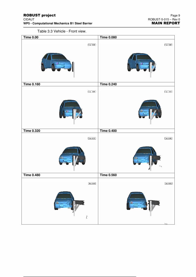
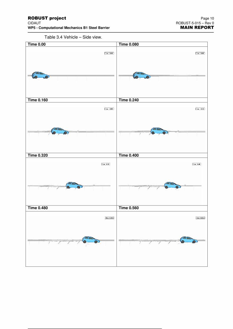
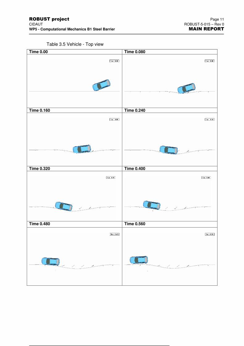
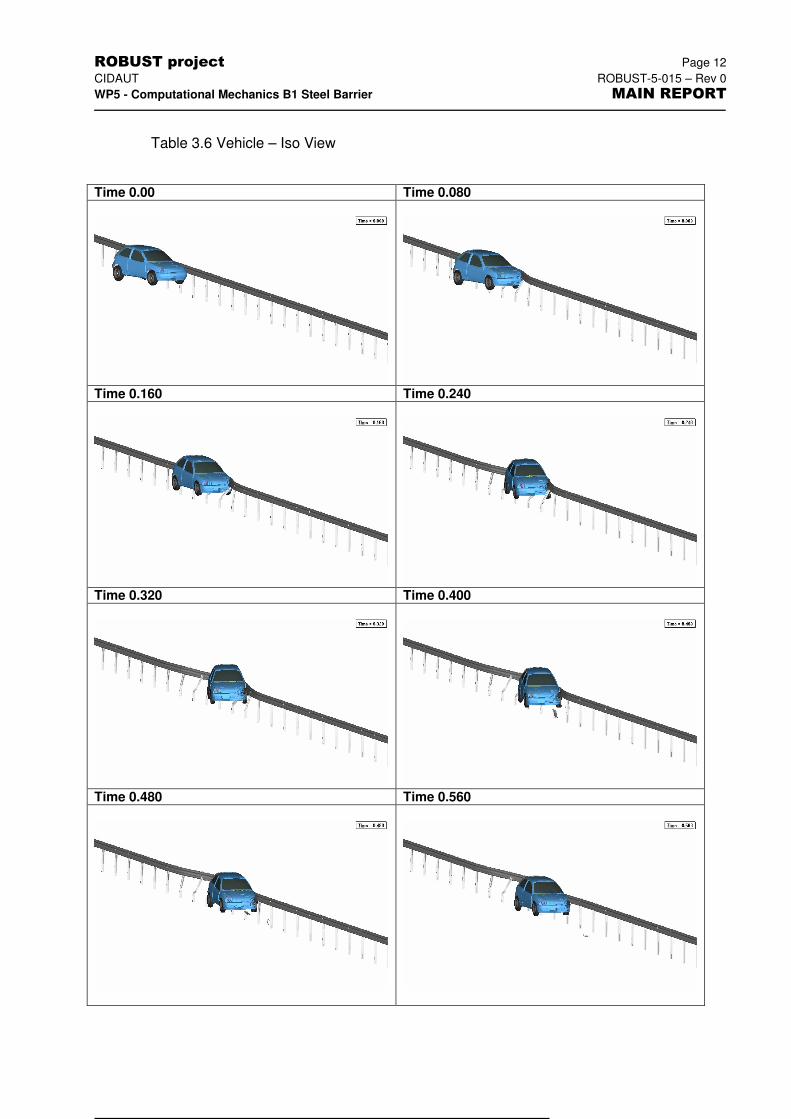
The vehicle hits the VRS at a velocity of 100 km/h and at an angle of 20 degrees. The vehicle leaves the VRS at an angle of 3.7 degrees. The trajectory is good in the simulation.
Vehicle damage TAD: NA
Vehicle damage VDI: NA
Vehicle cockpit def. index VCDI: NA
Major parts of vehicle detached: No
Plots of the vehicle:
4) Assessment of the impact severity
Impact severity for this model was assessed for two cases, c1.1 and c1.2, that differ only in the material law.
Post-processing procedure Accelerometer and rotation data, CFC 180. input into TRAP
Acceleration severity index, ASI: 0.59
Acceleration graphs: Yes
THIV: 22.2 km/h
Time of flight: 134 ms
Post-impact head deceleration, PHD: 25.3 g
Flail space: 0.6 x 0.3 m
Post-processing procedure Accelerometer and rotation data, CFC 180. input into TRAP
Acceleration severity index, ASI: 0.60
Acceleration graphs: Yes
THIV: 20.7 km/h
Time of flight: 139 ms
Post-impact head deceleration, PHD: 6.4 g
Flail space: 0.6 x 0.3 m
5) General statement
From the results above, it can be concluded that the crash protection system fulfils the requirements of the CEN standard with the exception of the PHD severity index in one of the cases.
ROBUST project Page 9
CIDAUT ROBUST-5-015 – Rev 0
WP5 - Computational Mechanics B1 Steel Barrier MAIN REPORT
Table 3.3 Vehicle - Front view.
Time 0.00 Time 0.080
Time 0.160 Time 0.240
Time 0.320 Time 0.400
Time 0.480 Time 0.560
ROBUST project Page 10
CIDAUT ROBUST-5-015 – Rev 0
WP5 - Computational Mechanics B1 Steel Barrier MAIN REPORT
Table 3.4 Vehicle – Side view.
Time 0.00 Time 0.080
Time 0.160 Time 0.240
Time 0.320 Time 0.400
Time 0.480 Time 0.560
ROBUST project Page 11
CIDAUT ROBUST-5-015 – Rev 0
WP5 - Computational Mechanics B1 Steel Barrier MAIN REPORT
Table 3.5 Vehicle - Top view
Time 0.00 Time 0.080
Time 0.160 Time 0.240
Time 0.320 Time 0.400
Time 0.480 Time 0.560
ROBUST project Page 12
CIDAUT ROBUST-5-015 – Rev 0
WP5 - Computational Mechanics B1 Steel Barrier MAIN REPORT
Table 3.6 Vehicle – Iso View
Time 0.00 Time 0.080
Time 0.160 Time 0.240
Time 0.320 Time 0.400
Time 0.480 Time 0.560

ROBUST project Page 13
CIDAUT ROBUST-5-015 – Rev 0
WP5 - Computational Mechanics B1 Steel Barrier MAIN REPORT
Table 3.7 Vehicle damage.
Top view Bottom view
Side view Side view
View View
ROBUST project Page 14
CIDAUT ROBUST-5-015 – Rev 0
WP5 - Computational Mechanics B1 Steel Barrier MAIN REPORT
4 BARRIER – B1 VS GEOMETRO. REDUCED LENGTH
4.1 General
The barrier used in the simulation represented the B1 barrier (ESP steel barrier, N2). The vehicle model was a light passenger vehicle, developed by CIDAUT for simulation with the PAM-CRASHTM code. This vehicle model has the same overall geometry as the Geometro model which was supplied as part of the project, and complies with the vehicle characteristics specified by EN1317 for 900-kg vehicle.
The simulation scenario consisted of the vehicle impacting the barrier with an initial speed of 100 km/h and an angle of 20 degrees.
The characteristics specific to this simulation were the ones deemed to provide a better agreement with the experimental crash test. They are:
� The barrier was modelled using a non-linear material model and represented by shell elements for all steel pieces that reproduced its geometry
� Part of the full length of the barrier was not modelled, but substituted by non-linear springs that behaved according to the same force-displacement law as the removed sections.
� Post embedment in soil was modelled by fixing posts 200 below ground level.
� Friction between the vehicle and the barrier was set to 0.
� Friction between the ground and the tyres was set to 0.6
4.2 Additional data
The following data and files supplement the result presentation of the simulation as presented in this chapter.
Excel worksheet file:
Rawdata file: B1-metroPAM-c1.zip
Animations:
- front view B1-c2_front.avi
- side view B1-c2_side.avi
- top view B1-c2_top.avi
-perspective B1-c2_iso.avi
4.3 Input data
4.3.1 Test item
ROBUST project Page 15
CIDAUT ROBUST-5-015 – Rev 0
WP5 - Computational Mechanics B1 Steel Barrier MAIN REPORT
Test item: ESP – N2 Temporary
Vehicle: Geometro - PAMCRASH Geometro
4.3.2 Test procedure
4) Test type – TB11
Impact speed: 103.5 km/h
Impact angle: 20 degrees
Impact point: About 26 metres from the beginning of the VRS, 8 m from the beginning of the reduced section
Spinning wheels: No
Inertial vehicle test mass: 904 kg
5) VRS model
Barrier type: ESP – N2
Number of posts: 12
Spacing: 2 m
Total length: 15 m
Element formulation/type: Shell elements.
Connection/Joints: Tied joints with failure
Foundation: Posts fixed to the soil
End anchoring: Non-linear springs
Soil (type and formulation): NA
Roadway: Modelled as rigid wall
6) Vehicle model
Light passenger vehicle, developed by CIDAUT for simulation with PAM-CRASHTM.
4.3.3 Analysis data
Timestep: Between 2 and 3 E-06
Precision: Single
Friction barrier/vehicle (static coefficient): 0.3
Friction barrier/vehicle (dynamic coefficient) 0.3
Friction wheel/ground (static coefficient) 0.6
Friction wheel/ground (dynamic coefficient) 0.6
Accelerometer location (mounting block) Coincident with vehicle cog
ROBUST project Page 16
CIDAUT ROBUST-5-015 – Rev 0
WP5 - Computational Mechanics B1 Steel Barrier MAIN REPORT
Sampling rate
Friction other:
1.0 E-4 for THP
NA
ROBUST project Page 17
CIDAUT ROBUST-5-015 – Rev 0
WP5 - Computational Mechanics B1 Steel Barrier MAIN REPORT
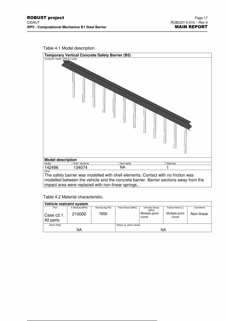
Table 4.1 Model description.
Temporary Vertical Concrete Safety Barrier (B5) Computer model, VRS for roads
Model description Nodes Shell elements Spot welds Materials
142486 134074 NA 1 Other
The safety barrier was modelled with shell elements. Contact with no friction was modelled between the vehicle and the concrete barrier. Barrier sections away from the impact area were replaced with non-linear springs..
Table 4.2 Material characteristic.
Vehicle restraint system Part E-Module [MPa] Density [kg/m3] Yield Stress [MPa] Ultimate Stress
[MPa] Failure Strain [-] Comments
Case c2.1. All parts
210000 7850 Multiple point curve
Multiple point curve
Non-linear
Strain Rate Stress vs. strain values
NA NA

ROBUST project Page 18
CIDAUT ROBUST-5-015 – Rev 0
WP5 - Computational Mechanics B1 Steel Barrier MAIN REPORT
4.4 Analysis results
6) VRS
Maximum global dynamic deflection: 1061 mm
Working width: 1119 mm
Maximum global permanent deflection: 1240 mm at the end of simulation
Length of contact: 10.4m approximately
Major parts fractured or detached: 6 posts detached from beam
Description of damage to test items: No
Ground anchorage’s meets design levels: Yes
Plot of test items:
7) Vehicle
Exit speed: 78.5 km/h
Exit angle: 11.5 degrees
Rebound distance: NA
Vehicle breaches barrier: No
Vehicle passes over the barrier: No
Vehicle within CEN “box”: NA
Vehicle rolls over after impact: No
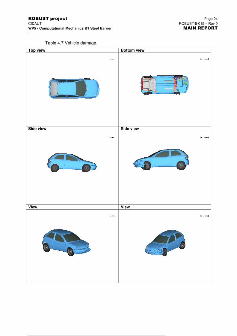
Damage to test vehicle:
ROBUST project Page 19
CIDAUT ROBUST-5-015 – Rev 0
WP5 - Computational Mechanics B1 Steel Barrier MAIN REPORT
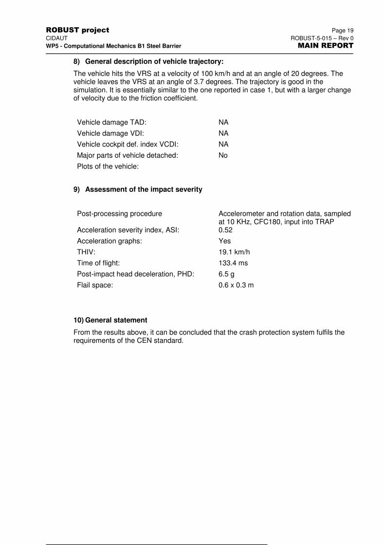
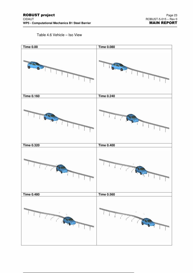
8) General description of vehicle trajectory:
The vehicle hits the VRS at a velocity of 100 km/h and at an angle of 20 degrees. The vehicle leaves the VRS at an angle of 3.7 degrees. The trajectory is good in the simulation. It is essentially similar to the one reported in case 1, but with a larger change of velocity due to the friction coefficient.
Vehicle damage TAD: NA
Vehicle damage VDI: NA
Vehicle cockpit def. index VCDI: NA
Major parts of vehicle detached: No
Plots of the vehicle:
9) Assessment of the impact severity
Post-processing procedure Accelerometer and rotation data, sampled at 10 KHz, CFC180, input into TRAP
Acceleration severity index, ASI: 0.52
Acceleration graphs: Yes
THIV: 19.1 km/h
Time of flight: 133.4 ms
Post-impact head deceleration, PHD: 6.5 g
Flail space: 0.6 x 0.3 m
10) General statement
From the results above, it can be concluded that the crash protection system fulfils the requirements of the CEN standard.
ROBUST project Page 20
CIDAUT ROBUST-5-015 – Rev 0
WP5 - Computational Mechanics B1 Steel Barrier MAIN REPORT
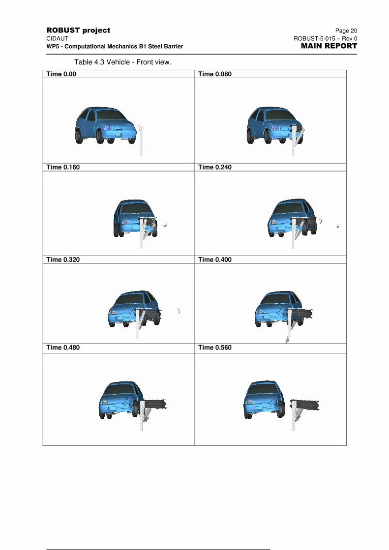
Table 4.3 Vehicle - Front view.
Time 0.00 Time 0.080
Time 0.160 Time 0.240
Time 0.320 Time 0.400
Time 0.480 Time 0.560
ROBUST project Page 21
CIDAUT ROBUST-5-015 – Rev 0
WP5 - Computational Mechanics B1 Steel Barrier MAIN REPORT
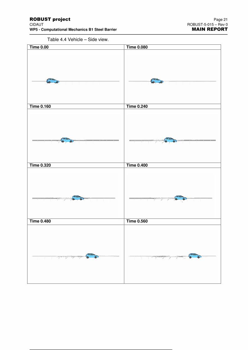
Table 4.4 Vehicle – Side view.
Time 0.00 Time 0.080
Time 0.160 Time 0.240
Time 0.320 Time 0.400
Time 0.480 Time 0.560
ROBUST project Page 22
CIDAUT ROBUST-5-015 – Rev 0
WP5 - Computational Mechanics B1 Steel Barrier MAIN REPORT
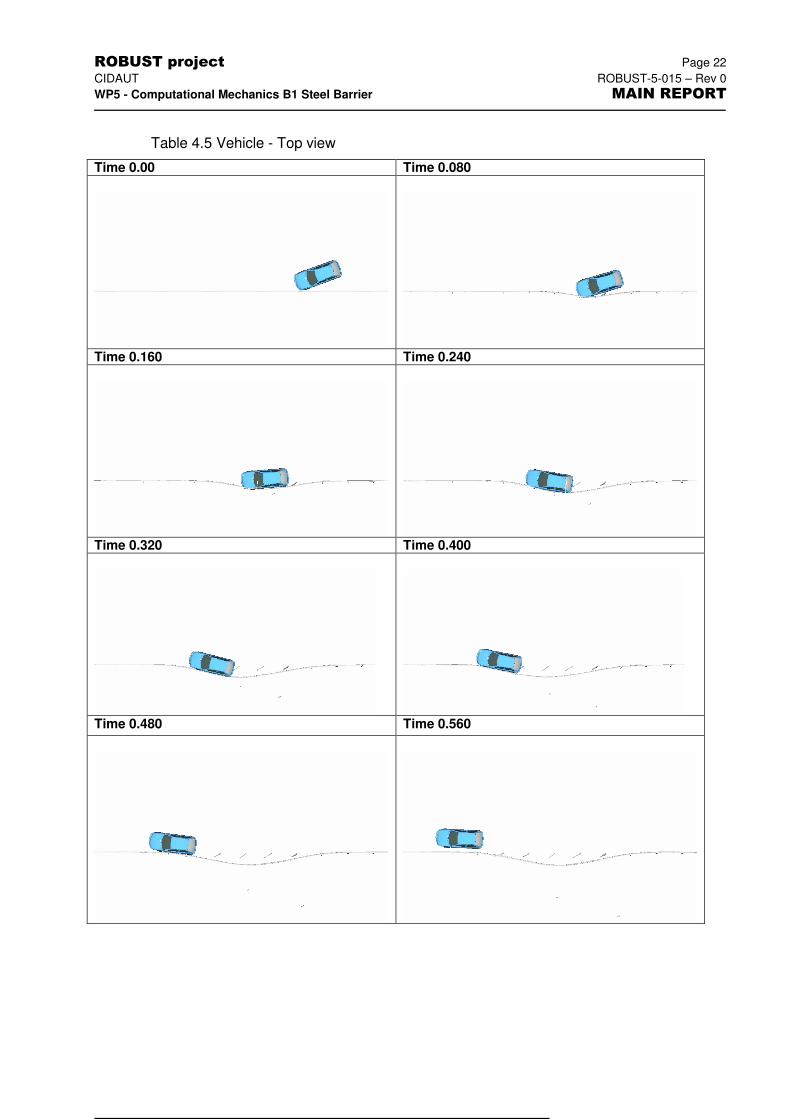
Table 4.5 Vehicle - Top view
Time 0.00 Time 0.080
Time 0.160 Time 0.240
Time 0.320 Time 0.400
Time 0.480 Time 0.560
ROBUST project Page 23
CIDAUT ROBUST-5-015 – Rev 0
WP5 - Computational Mechanics B1 Steel Barrier MAIN REPORT
Table 4.6 Vehicle – Iso View
Time 0.00 Time 0.080
Time 0.160 Time 0.240
Time 0.320 Time 0.400
Time 0.480 Time 0.560
ROBUST project Page 24
CIDAUT ROBUST-5-015 – Rev 0
WP5 - Computational Mechanics B1 Steel Barrier MAIN REPORT
Table 4.7 Vehicle damage.
Top view Bottom view
Side view Side view
View View
ROBUST project Page 25
CIDAUT ROBUST-5-015 – Rev 0
WP5 - Computational Mechanics B1 Steel Barrier MAIN REPORT
5 BARRIER – B1. REDUCED MODELS (SIGMA POSTS)
5.1 General
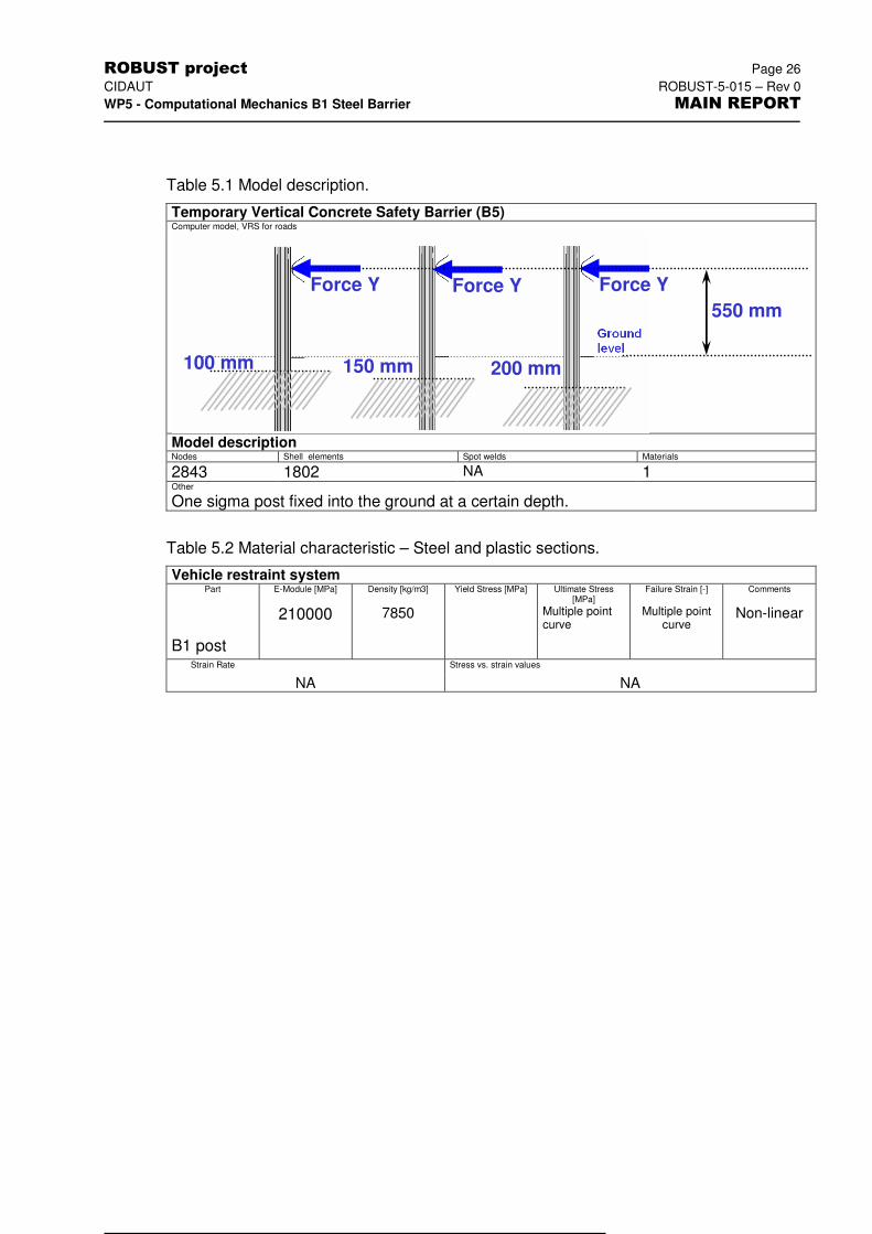
The steel ESP barrier comprises sigma-shaped posts. A detailed study was performed on these posts, based also on information from static pull-push tests.
The characteristics specific to this simulation are:
� The barrier posts were modelled by shell elements. To model the embedment, their lower part was rigidly fixed in the ground, at a certain depth below ground level.
� Force was applied on posts externally and the relationships between forces and displacements were measured.
5.2 Additional data
The following data and files supplement the result presentation of the simulation as presented in this chapter.
Excel worksheet file:
Rawdata file:
Animations:
- iso view B1-c31_iso.avi: pull test, concreted post, direction Y
- iso view B1-c32_iso.avi: pull test, concreted post, direction X
- side view B1-c33_side.avi: push test, 100mm-driven post, direction Y
- side view B1-c34_side.avi: push test, 150mm-driven post, direction Y
- side view B1-c33_side.avi: push test, 200mm-driven post, direction Y
5.3 Input data
5.3.1 Test item
Test item: ESP-N2 barrier sigma post
Vehicle: -
5.3.2 Test procedure
7) Test type – Pull test
ROBUST project Page 26
CIDAUT ROBUST-5-015 – Rev 0
WP5 - Computational Mechanics B1 Steel Barrier MAIN REPORT
Table 5.1 Model description.
Temporary Vertical Concrete Safety Barrier (B5) Computer model, VRS for roads
Model description Nodes Shell elements Spot welds Materials
2843 1802 NA 1 Other
One sigma post fixed into the ground at a certain depth.
Table 5.2 Material characteristic – Steel and plastic sections.
Vehicle restraint system Part E-Module [MPa] Density [kg/m3] Yield Stress [MPa] Ultimate Stress
[MPa] Failure Strain [-] Comments
B1 post
210000 7850 Multiple point curve
Multiple point curve
Non-linear
Strain Rate Stress vs. strain values
NA NA
Force Y Force Y Force Y
550 mm
100 mm 150 mm 200 mm
ROBUST project Page 27
CIDAUT ROBUST-5-015 – Rev 0
WP5 - Computational Mechanics B1 Steel Barrier MAIN REPORT
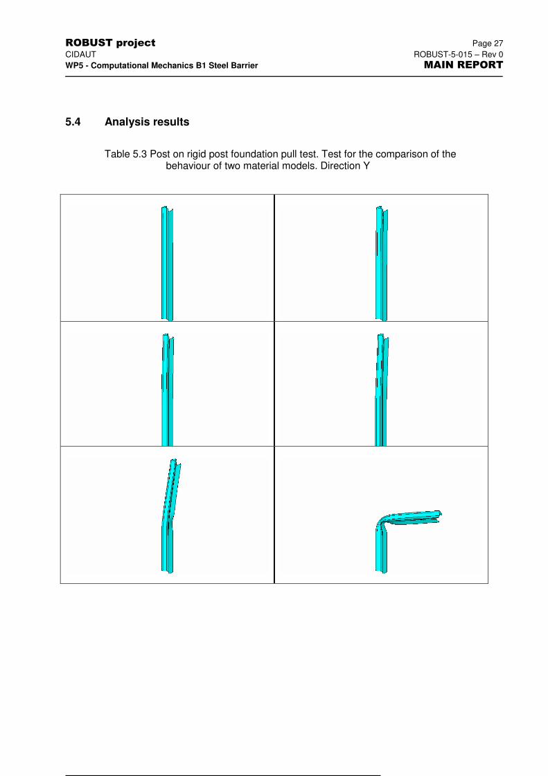
5.4 Analysis results
Table 5.3 Post on rigid post foundation pull test. Test for the comparison of the behaviour of two material models. Direction Y
ROBUST project Page 28
CIDAUT ROBUST-5-015 – Rev 0
WP5 - Computational Mechanics B1 Steel Barrier MAIN REPORT
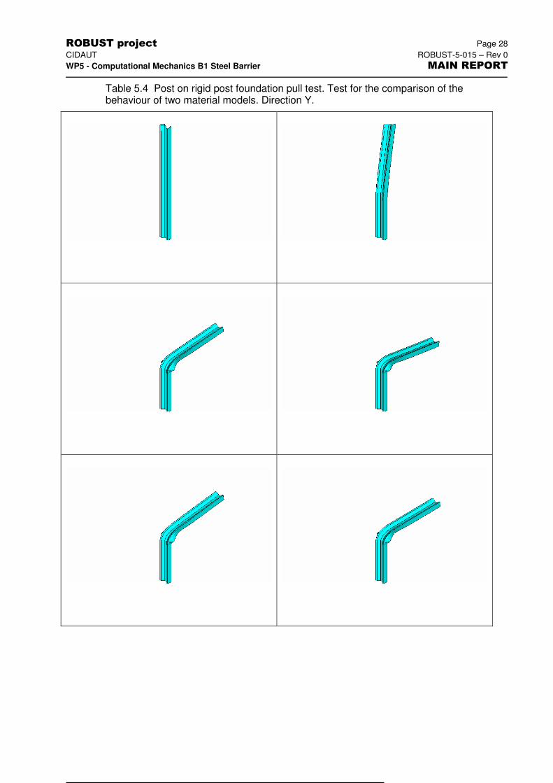
Table 5.4 Post on rigid post foundation pull test. Test for the comparison of the behaviour of two material models. Direction Y.
ROBUST project Page 29
CIDAUT ROBUST-5-015 – Rev 0
WP5 - Computational Mechanics B1 Steel Barrier MAIN REPORT
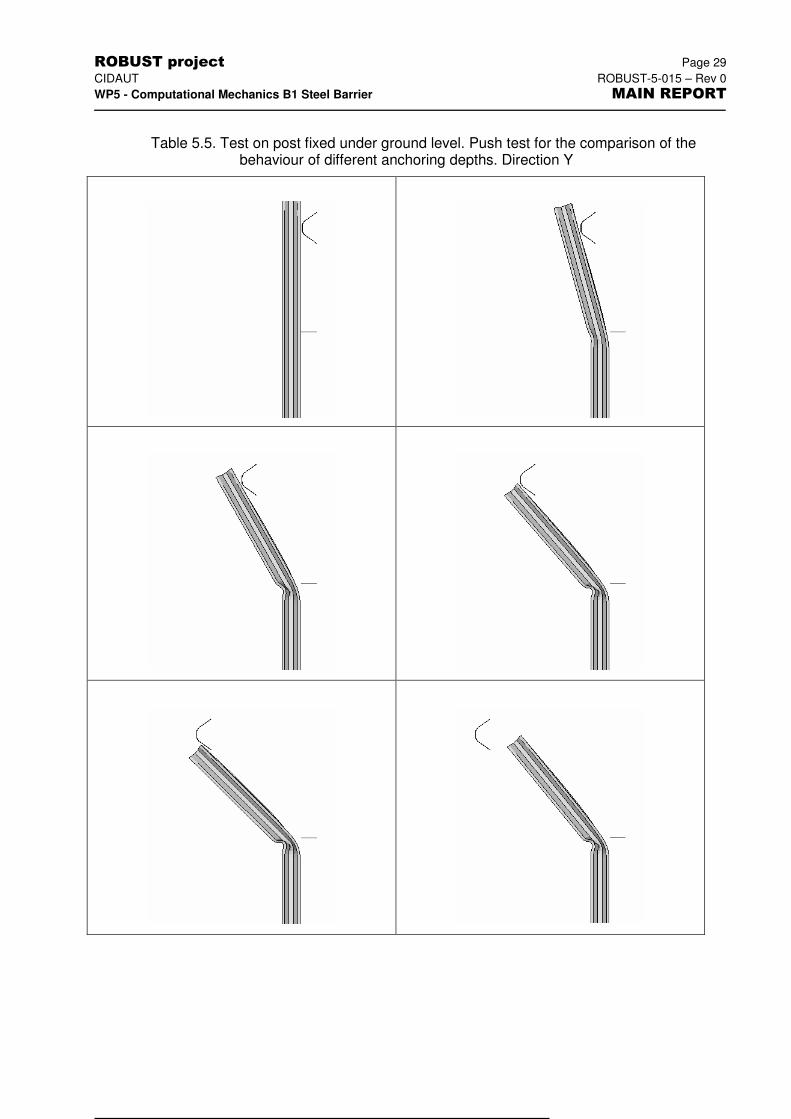
Table 5.5. Test on post fixed under ground level. Push test for the comparison of the
behaviour of different anchoring depths. Direction Y
ROBUST project Page 30
CIDAUT ROBUST-5-015 – Rev 0
WP5 - Computational Mechanics B1 Steel Barrier MAIN REPORT
6 REFERENCES
Ref. 1 EN 1317-1: Road restraint systems – Part 1: Terminology and general criteria for test methods. European Committee for Standardization, April 1998.
Ref. 2 EN 1317-2: Road restraint systems – Part 2: Performance classes, impact test acceptance criteria and test methods for safety barriers. European Committee for Standardization, April 1998