Embed Size (px)
Citation preview
Lecture – 38
Robust Nonlinear Control of Aircrafts Using Neuro-adaptive Augmented Dynamic Inversion
Dr. Radhakant PadhiAsst. Professor
Dept. of Aerospace EngineeringIndian Institute of Science - Bangalore
ADVANCED CONTROL SYSTEM DESIGN Dr. Radhakant Padhi, AE Dept., IISc-Bangalore
2
References
Radhakant Padhi, Narayan P. Rao, Siddharth Goyal and Abha Tripathi, “A Model-Following Neuro-Adaptive Approach for Robust Control of High Performance Aircrafts”, Automatic Control in Aerospace, Vol. 3, No. 1, May 2010.
ADVANCED CONTROL SYSTEM DESIGN Dr. Radhakant Padhi, AE Dept., IISc-Bangalore
3
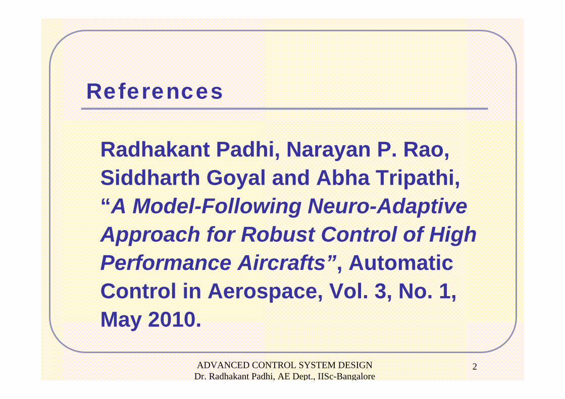
Problem StatementPilot Commands:• Case -1: Longitudinal
(Roll Rate = 0, Normal Acceleration, Lateral Acceleration = 0, Total Velocity)
• Case -2: Lateral (Roll Rate, Height, Lateral Acceleration = 0, Total Velocity)
Turn Coordination: Lateral acceleration command is zero
Goal:• Airplane responds to the pilot commands “quickly” & “nicely”• The control design should have sufficient robustness for
parametric inaccuracies (mass, MI and aerodynamic coefficients)
Note: Essentially it is a Robust Tracking problem
ADVANCED CONTROL SYSTEM DESIGN Dr. Radhakant Padhi, AE Dept., IISc-Bangalore
4
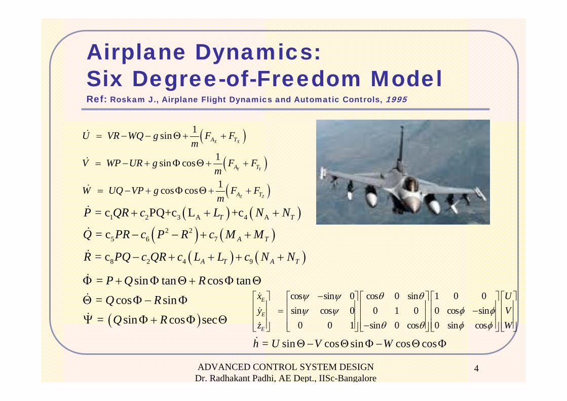
Airplane Dynamics: Six Degree-of-Freedom ModelRef: Roskam J., Airplane Flight Dynamics and Automatic Controls, 1995
( ) ( )( ) ( )
( ) ( )
1 2 3 A 4 A
2 25 6 7
8 2 4 9
= c PQ+c L +c
= c
= c
T T
A T
A T A T
P QR c L N N
Q PR c P R c M M
R PQ c QR c L L c N N
+ + +
− − + +
− + + + +
( )
( )
( )
1 sin
1 sin cos
1 cos cos
X X
Y Y
Z Z
A T
A T
A T
U VR WQ g F Fm
V WP UR g F Fm
W UQ VP g F Fm
= − − Θ+ +
= − + Φ Θ+ +
= − + Φ Θ+ +
( )
= sin tan cos tan = cos sin = sin cos sec
P Q RQ R
Q R
Φ + Φ Θ+ Φ Θ
Θ Φ − Φ
Ψ Φ+ Φ Θ
= sin cos sin cos cosh U V WΘ− Θ Φ − Θ Φ
cos sin 0 cos 0 sin 1 0 0sin cos 0 0 1 0 0 cos sin
0 0 1 sin 0 cos 0 sin cos
E
E
E
x Uy Vz W
ψ ψ θ θψ ψ φ φ
θ θ φ φ
−⎡ ⎤ ⎡ ⎤ ⎡ ⎤ ⎡ ⎤ ⎡ ⎤⎢ ⎥ ⎢ ⎥ ⎢ ⎥ ⎢ ⎥ ⎢ ⎥= −⎢ ⎥ ⎢ ⎥ ⎢ ⎥ ⎢ ⎥ ⎢ ⎥⎢ ⎥ ⎢ ⎥ ⎢ ⎥ ⎢ ⎥ ⎢ ⎥−⎣ ⎦ ⎣ ⎦ ⎣ ⎦ ⎣ ⎦ ⎣ ⎦
ADVANCED CONTROL SYSTEM DESIGN Dr. Radhakant Padhi, AE Dept., IISc-Bangalore
5
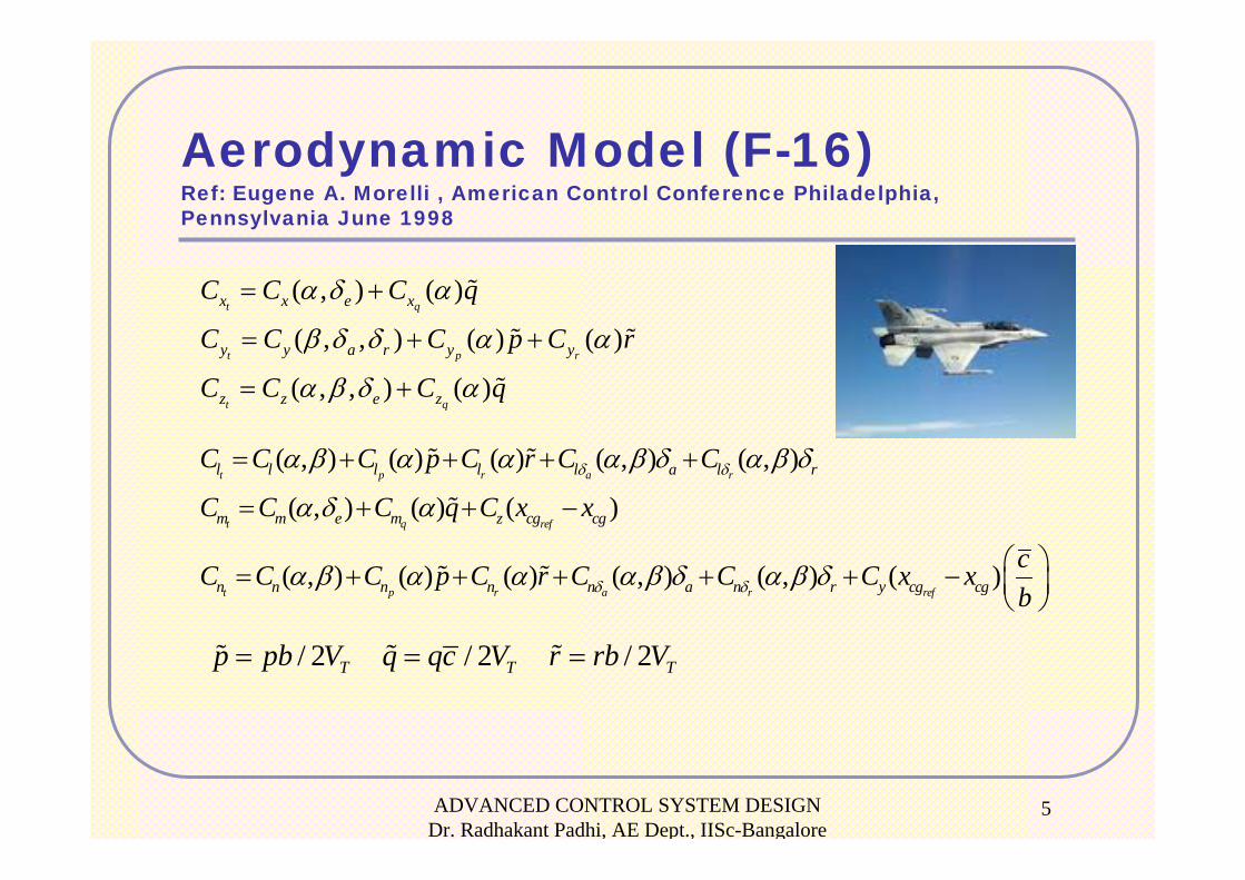
Aerodynamic Model (F-16)Ref: Eugene A. Morelli , American Control Conference Philadelphia, Pennsylvania June 1998
( , ) ( )
( , , ) ( ) ( )
( , , ) ( )
t q
t p r
t q
x x e x
y y a r y y
z z e z
C C C q
C C C p C r
C C C q
α δ α
β δ δ α α
α β δ α
= +
= + +
= +
( , ) ( ) ( ) ( , ) ( , )
( , ) ( ) ( )
( , ) ( ) ( ) ( , ) ( , ) ( )
t p r a r
t q ref
t p r a r ref
l l l l l a l r
m m e m z cg cg
n n n n n a n r y cg cg
C C C p C r C C
C C C q C x x
cC C C p C r C C C x xb
δ δ
δ δ
α β α α α β δ α β δ
α δ α
α β α α α β δ α β δ
= + + + +
= + + −
⎛ ⎞= + + + + + − ⎜ ⎟⎝ ⎠
/ 2 / 2 / 2T T Tp pb V q qc V r rb V= = =

ADVANCED CONTROL SYSTEM DESIGN Dr. Radhakant Padhi, AE Dept., IISc-Bangalore
6
Equations in Desired Form
( ) ( )V V V cX f X g X U= + ⎡ ⎤⎣ ⎦
( ) ( )R R R cX f X g X U= + ⎡ ⎤⎣ ⎦
[ ]TT E EX V P Q R X Y hα β Φ Θ Ψ
[ ]TVX U V W
[ ]TRX P Q R
[ ]TAX Φ Θ Ψ
[ ] [ ][ ]T Tc AER T a e rU U U Tδ δ δ
where
ADVANCED CONTROL SYSTEM DESIGN Dr. Radhakant Padhi, AE Dept., IISc-Bangalore
7
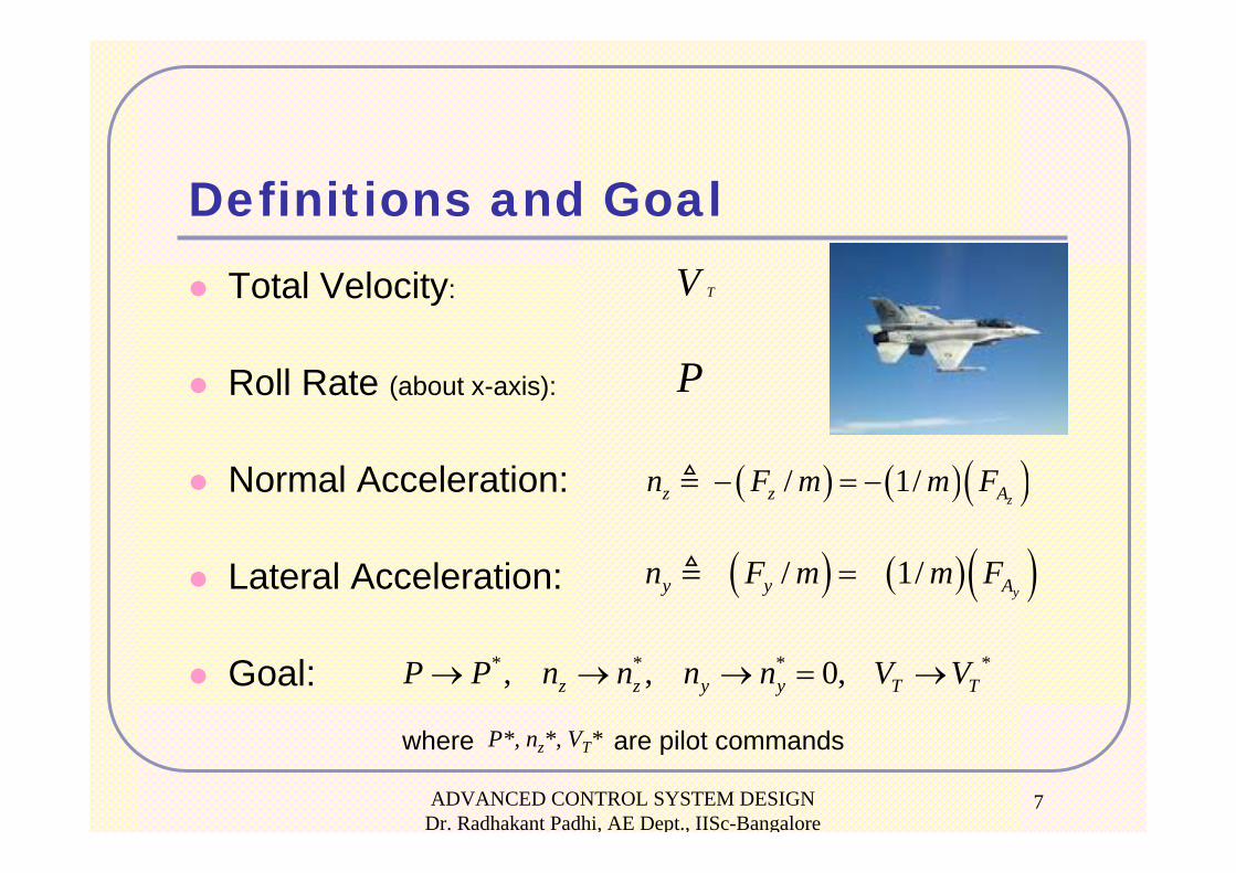
Definitions and GoalTotal Velocity:
Roll Rate (about x-axis):
Normal Acceleration:
Lateral Acceleration:
Goal:
P
where are pilot commands
( ) ( )( )/ 1/zz z An F m m F− = −
( ) ( )( )/ 1/yy y An F m m F=
P*, nz*, VT*
* * * *, , 0,z z y y T TP P n n n n V V→ → → = →
TV
ADVANCED CONTROL SYSTEM DESIGN Dr. Radhakant Padhi, AE Dept., IISc-Bangalore
8
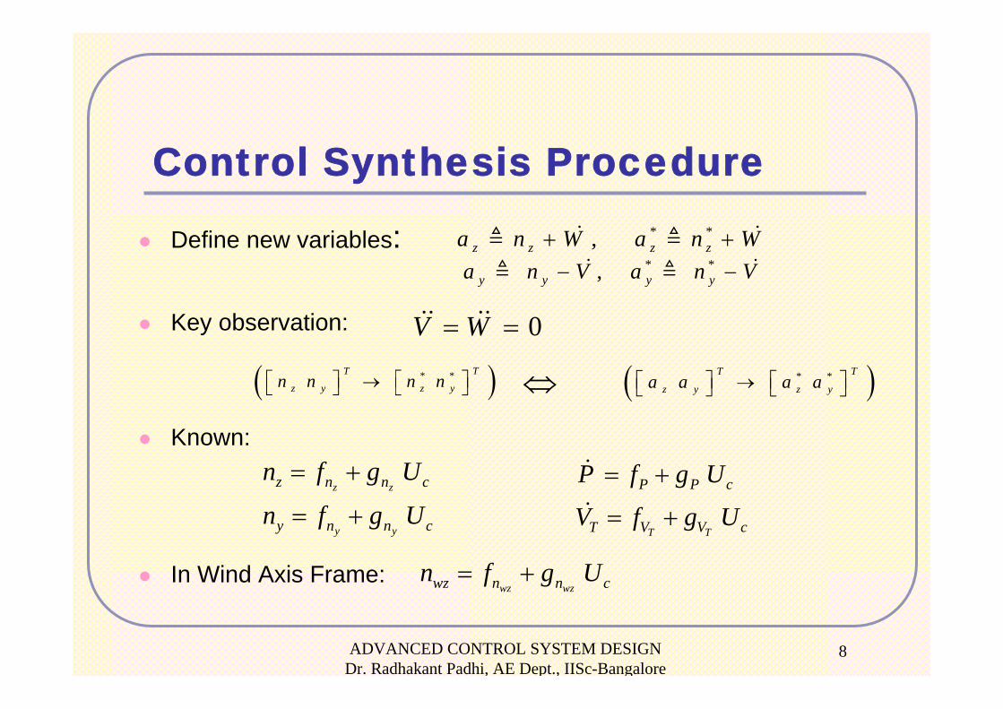
Control Synthesis Procedure
Define new variables:
Key observation:
Known:
In Wind Axis Frame:
* *,y y y ya n V a n V− −
* *,z z z za n W a n W+ +
⇔( )* * TT
z y z yn n n n⎡ ⎤⎡ ⎤ →⎣ ⎦ ⎣ ⎦ ( )* * TT
z y z ya a a a⎡ ⎤⎡ ⎤ →⎣ ⎦ ⎣ ⎦
z z
y y
z n n c
y n n c
n f g U
n f g U
= +
= +T T
P P c
T V V c
P f g U
V f g U
= +
= +
0V W= =
wz wzwz n n cn f g U= +
ADVANCED CONTROL SYSTEM DESIGN Dr. Radhakant Padhi, AE Dept., IISc-Bangalore
9
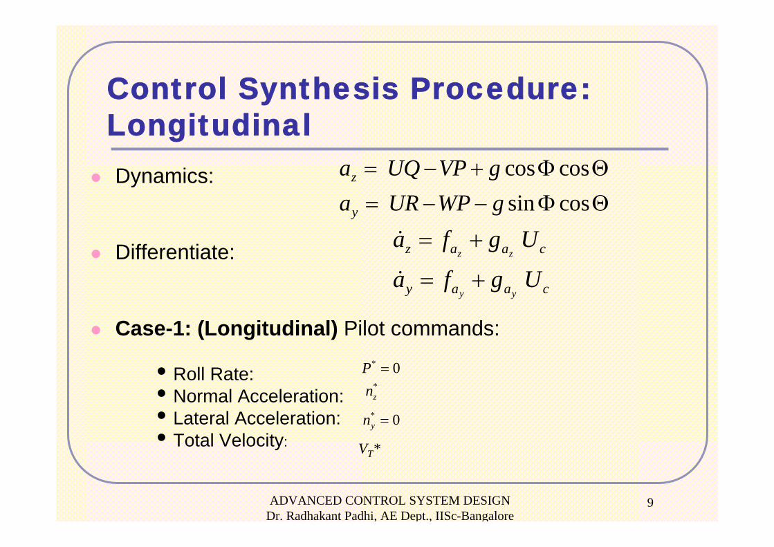
Control Synthesis Procedure:LongitudinalDynamics:
Differentiate:
Case-1: (Longitudinal) Pilot commands:
• Roll Rate: • Normal Acceleration:• Lateral Acceleration:• Total Velocity:
cos cossin cos
z
y
a UQ VP ga UR WP g
= − + Φ Θ= − − Φ Θ
z z
y y
z a a c
y a a c
a f g U
a f g U
= +
= +
* 0P =*zn
* 0yn =
VT*
ADVANCED CONTROL SYSTEM DESIGN Dr. Radhakant Padhi, AE Dept., IISc-Bangalore
10
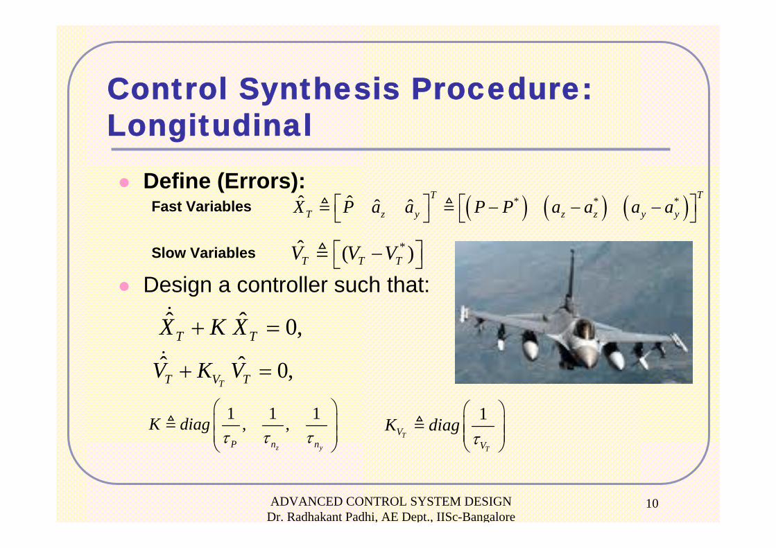
Control Synthesis Procedure:Longitudinal
Define (Errors):Fast Variables
Slow Variables
Design a controller such that:
*ˆ ( )T T TV V V⎡ ⎤−⎣ ⎦
( ) ( ) ( )* * *ˆ ˆ ˆ ˆTT
T z y z z y yX P a a P P a a a a⎡ ⎤⎡ ⎤ − − −⎣ ⎦ ⎣ ⎦
ˆ ˆ 0,T TX K X+ =
1 1 1, ,z yP n n
K diagτ τ τ
⎛ ⎞⎜ ⎟⎜ ⎟⎝ ⎠
ˆ ˆ 0,TT V TV K V+ =
1T
T
VV
K diagτ
⎛ ⎞⎜ ⎟⎜ ⎟⎝ ⎠
ADVANCED CONTROL SYSTEM DESIGN Dr. Radhakant Padhi, AE Dept., IISc-Bangalore
11
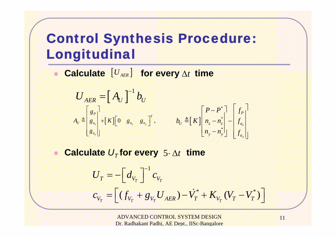
Control Synthesis Procedure:Longitudinal
Calculate for every time
Calculate UT for every time
[ ]AERU tΔ
5 t⋅ Δ
[ ] 1AER U UU A b−=
[ ] 0 ,z z y
y
PT
U a n n
a
gA g K g g
g
⎡ ⎤⎢ ⎥
⎡ ⎤+⎢ ⎥ ⎣ ⎦⎢ ⎥⎢ ⎥⎣ ⎦
[ ]*
*
*z
y
P
U z z a
y y a
P P fb K n n f
n n f
⎡ ⎤⎡ ⎤−⎢ ⎥⎢ ⎥− − ⎢ ⎥⎢ ⎥⎢ ⎥⎢ ⎥−⎣ ⎦ ⎢ ⎥⎣ ⎦
1
* *( ) ( )T T
T T T T
T V V
V V V AER T V T T
U d c
c f g U V K V V
−⎡ ⎤= − ⎣ ⎦
⎡ ⎤= + − + −⎣ ⎦
ADVANCED CONTROL SYSTEM DESIGN Dr. Radhakant Padhi, AE Dept., IISc-Bangalore
12
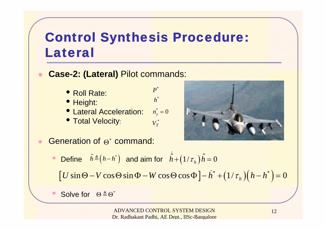
Control Synthesis Procedure:LateralCase-2: (Lateral) Pilot commands:
• Roll Rate: • Height:• Lateral Acceleration:• Total Velocity:
Generation of command:
• Define and aim for
• Solve for
*Θ
( )*h h h− ( )ˆ ˆ1/ 0hh hτ+ =
[ ] ( )( )* *sin cos sin cos cos 1/ 0hU V W h h hτΘ − Θ Φ − Θ Φ − + − =
*Θ Θ
*P*h
* 0yn =*VT
ADVANCED CONTROL SYSTEM DESIGN Dr. Radhakant Padhi, AE Dept., IISc-Bangalore
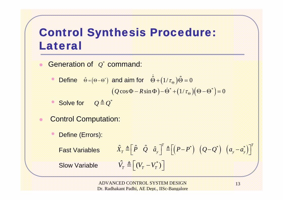
13
Control Synthesis Procedure:Lateral
Generation of command:
• Define and aim for
• Solve for
Control Computation:
• Define (Errors):
Fast Variables
Slow Variable
*Q
( )*Θ = Θ−Θ ( )ˆ ˆ1/ 0τΘΘ + Θ =
( ) ( )( )* *cos sin 1/ 0Q R τΘΦ − Φ −Θ + Θ−Θ =*Q Q
( ) ( ) ( )* * *ˆˆ ˆ ˆT T
T y y yX P Q a P P Q Q a a⎡ ⎤ ⎡ ⎤− − −⎣ ⎦⎣ ⎦*ˆ ( )T T TV V V⎡ ⎤−⎣ ⎦
ADVANCED CONTROL SYSTEM DESIGN Dr. Radhakant Padhi, AE Dept., IISc-Bangalore
14
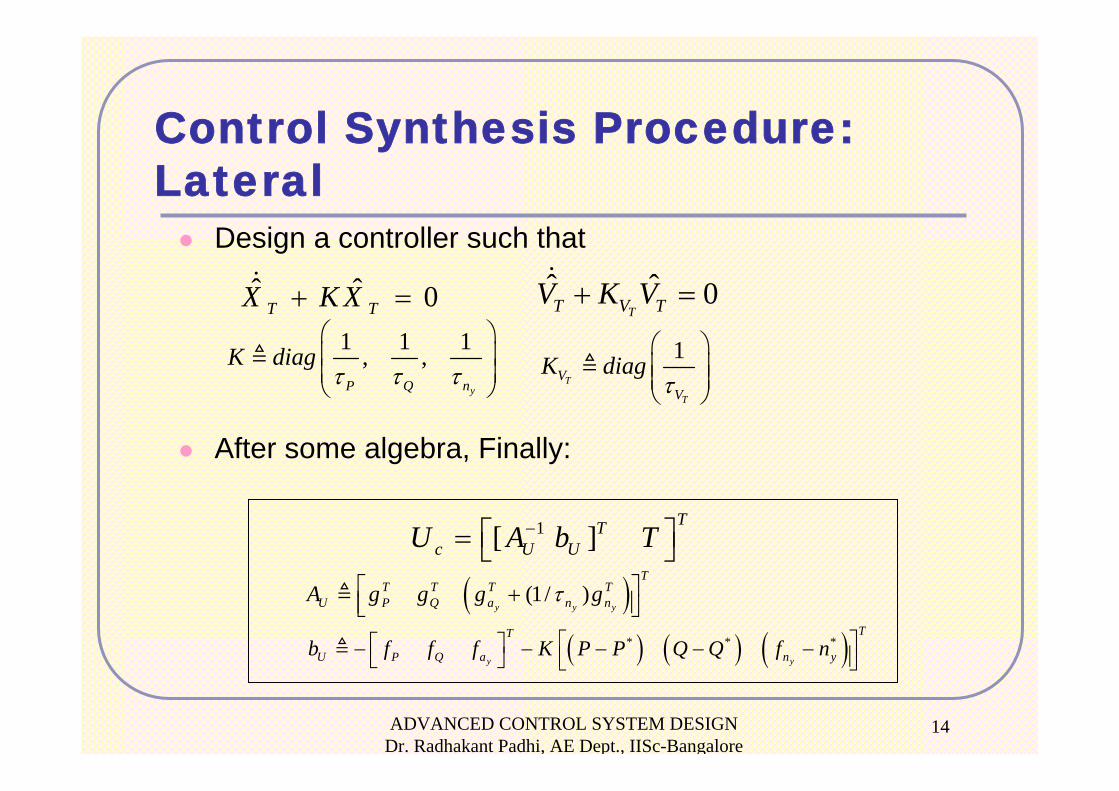
Control Synthesis Procedure:Lateral
Design a controller such that
After some algebra, Finally:
1T
T
VV
K diagτ
⎛ ⎞⎜ ⎟⎜ ⎟⎝ ⎠
ˆ ˆ 0T TX K X+ =1 1 1, ,
yP Q n
K diagτ τ τ
⎛ ⎞⎜ ⎟⎜ ⎟⎝ ⎠
1[ ]TT
c U UU A b T−⎡ ⎤= ⎣ ⎦
( )(1/ )y y y
TT T T T
U P Q a n nA g g g gτ⎡ ⎤+⎢ ⎥⎣ ⎦
( ) ( ) ( )* * *y y
TT
U P Q a n yb f f f K P P Q Q f n⎡ ⎤⎡ ⎤− − − − −⎢ ⎥⎣ ⎦ ⎣ ⎦
ˆ ˆ 0TT V TV K V+ =
ADVANCED CONTROL SYSTEM DESIGN Dr. Radhakant Padhi, AE Dept., IISc-Bangalore
15
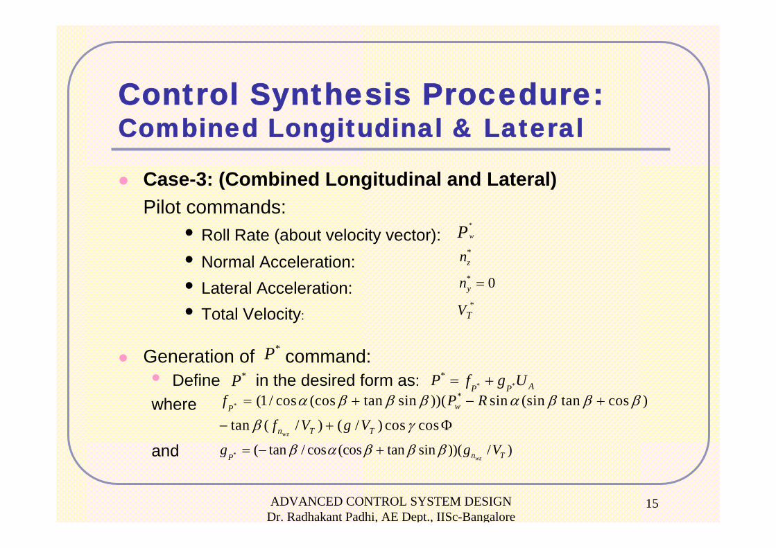
Control Synthesis Procedure:Combined Longitudinal & Lateral
Case-3: (Combined Longitudinal and Lateral) Pilot commands:
• Roll Rate (about velocity vector): • Normal Acceleration:• Lateral Acceleration:• Total Velocity:
Generation of command:• Define in the desired form as: where
and * ( tan / cos (cos tan sin ))( / )wzn TP
g g Vβ α β β β= − +
*P
* **
AP PP f g U= +
**(1/ cos (cos tan sin ))( sin (sin tan cos )
tan ( / ) ( / ) cos coswz
wP
n T T
f P R
f V g V
α β β β α β β β
β γ
= + − +
− + Φ
*wP
*zn* 0yn =*VT
*P
ADVANCED CONTROL SYSTEM DESIGN Dr. Radhakant Padhi, AE Dept., IISc-Bangalore
16
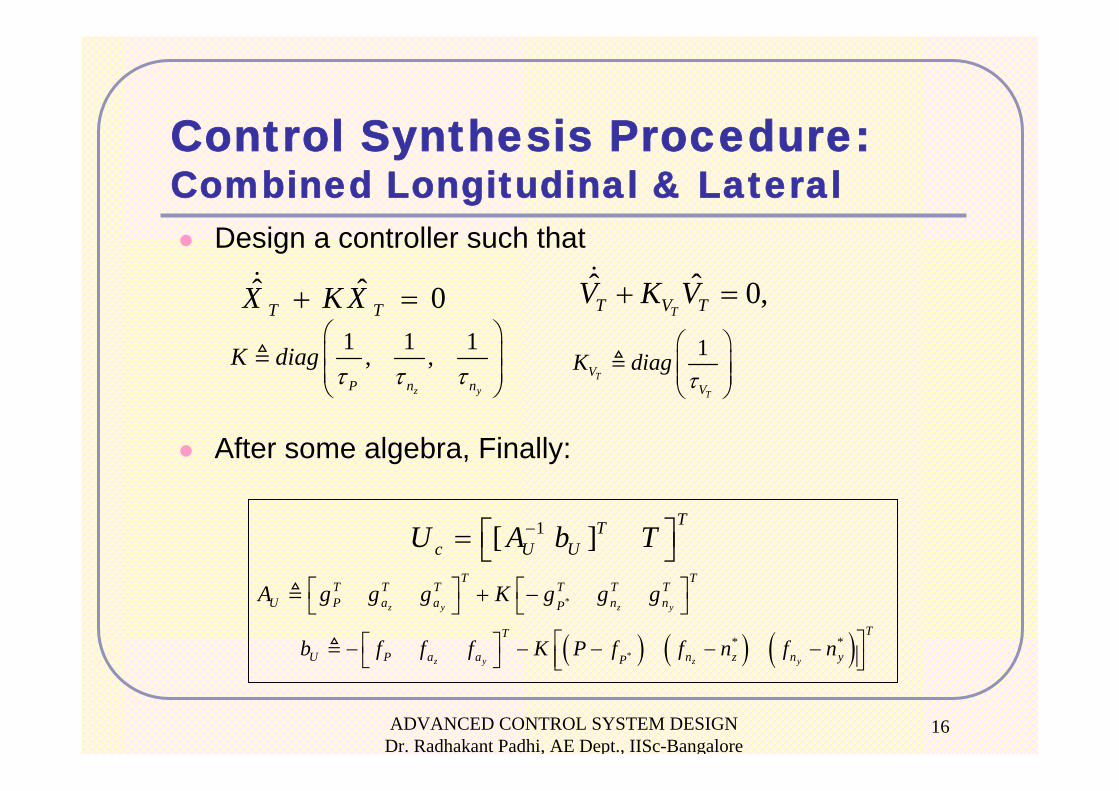
Control Synthesis Procedure:Combined Longitudinal & Lateral
Design a controller such that
After some algebra, Finally:
ˆ ˆ 0,TT V TV K V+ =ˆ ˆ 0T TX K X+ =
1[ ]TT
c U UU A b T−⎡ ⎤= ⎣ ⎦*z y z y
T TT T T T T T
U P a a n nPA g g g K g g g⎡ ⎤ ⎡ ⎤+ −⎣ ⎦ ⎣ ⎦
( ) ( ) ( )** *
z y z y
TT
U P a a n z n yPb f f f K P f f n f n⎡ ⎤⎡ ⎤− − − − −⎢ ⎥⎣ ⎦ ⎣ ⎦
1 1 1, ,z yP n n
K diagτ τ τ
⎛ ⎞⎜ ⎟⎜ ⎟⎝ ⎠
1T
T
VV
K diagτ
⎛ ⎞⎜ ⎟⎜ ⎟⎝ ⎠
ADVANCED CONTROL SYSTEM DESIGN Dr. Radhakant Padhi, AE Dept., IISc-Bangalore
17
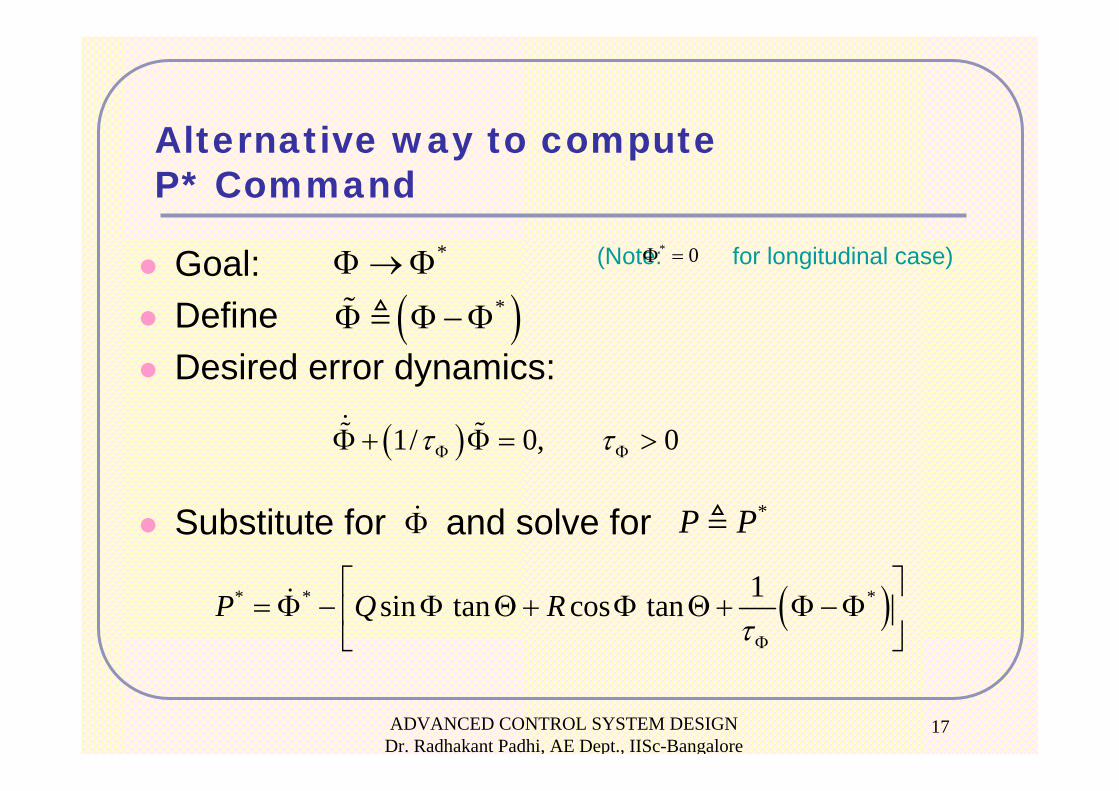
Alternative way to compute P* Command
Goal:DefineDesired error dynamics:
Substitute for and solve for
*Φ→Φ
( )*Φ Φ−Φ
( )1/ 0, 0τ τΦ ΦΦ + Φ = >
Φ *P P
( )* * *1sin tan cos tanP Q RτΦ
⎡ ⎤= Φ − Φ Θ+ Φ Θ+ Φ −Φ⎢ ⎥
⎣ ⎦
(Note: for longitudinal case)* 0Φ =
ADVANCED CONTROL SYSTEM DESIGN Dr. Radhakant Padhi, AE Dept., IISc-Bangalore
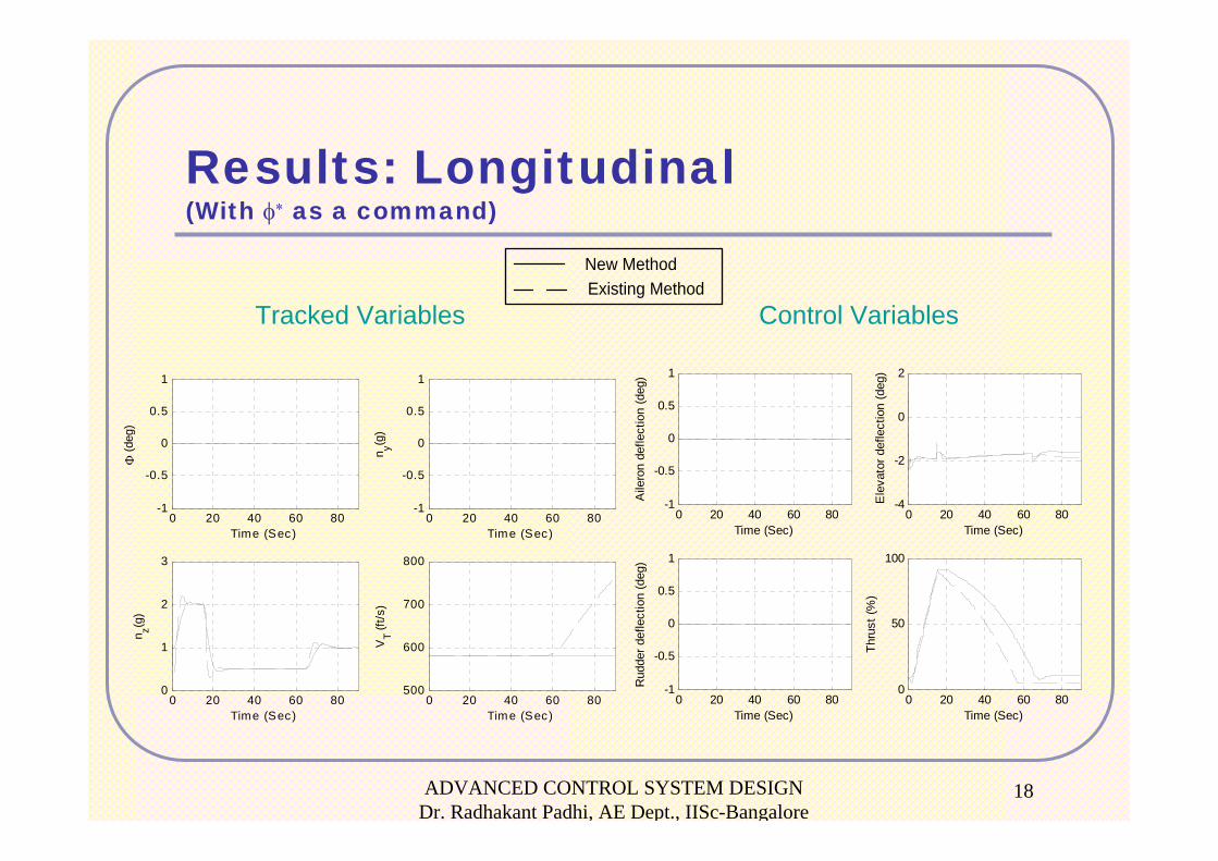
18
Results: Longitudinal(With φ∗ as a command)
Tracked Variables Control Variables
0 20 40 60 80-1
-0.5
0
0.5
1
Time (Sec)
Φ (d
eg)
0 20 40 60 80-1
-0.5
0
0.5
1
Time (Sec)
n y(g)
0 20 40 60 800
1
2
3
Time (Sec)
n z(g)
0 20 40 60 80500
600
700
800
Time (Sec)
VT (f
t/s)
0 20 40 60 800
50
100
Time (Sec)
Thru
st (%
)
0 20 40 60 80-1
-0.5
0
0.5
1
Time (Sec)
Aile
ron
defle
ctio
n (d
eg)
0 20 40 60 80-4
-2
0
2
Time (Sec)
Ele
vato
r def
lect
ion
(deg
)
0 20 40 60 80-1
-0.5
0
0.5
1
Time (Sec)
Rud
der d
efle
ctio
n (d
eg)
New MethodExisting Method
ADVANCED CONTROL SYSTEM DESIGN Dr. Radhakant Padhi, AE Dept., IISc-Bangalore
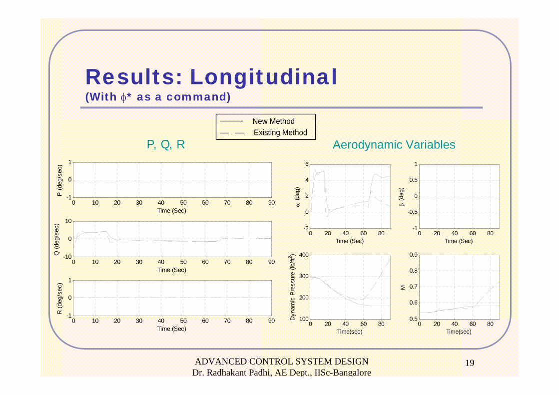
19
P, Q, R Aerodynamic Variables
Results: Longitudinal(With φ* as a command)
0 10 20 30 40 50 60 70 80 90-1
0
1
Time (Sec)
P (d
eg/s
ec)
0 10 20 30 40 50 60 70 80 90-10
0
10
Time (Sec)
Q (d
eg/s
ec)
0 10 20 30 40 50 60 70 80 90-1
0
1
Time (Sec)
R (d
eg/s
ec)
0 20 40 60 80-2
0
2
4
6
Time (Sec)
α (d
eg)
0 20 40 60 80-1
-0.5
0
0.5
1
Time (Sec)
β (d
eg)
0 20 40 60 80100
200
300
400
Time(sec)
Dyn
amic
Pre
ssur
e (lb
/ft2 )
0 20 40 60 800.5
0.6
0.7
0.8
0.9
Time(sec)
M
New MethodExisting Method
ADVANCED CONTROL SYSTEM DESIGN Dr. Radhakant Padhi, AE Dept., IISc-Bangalore
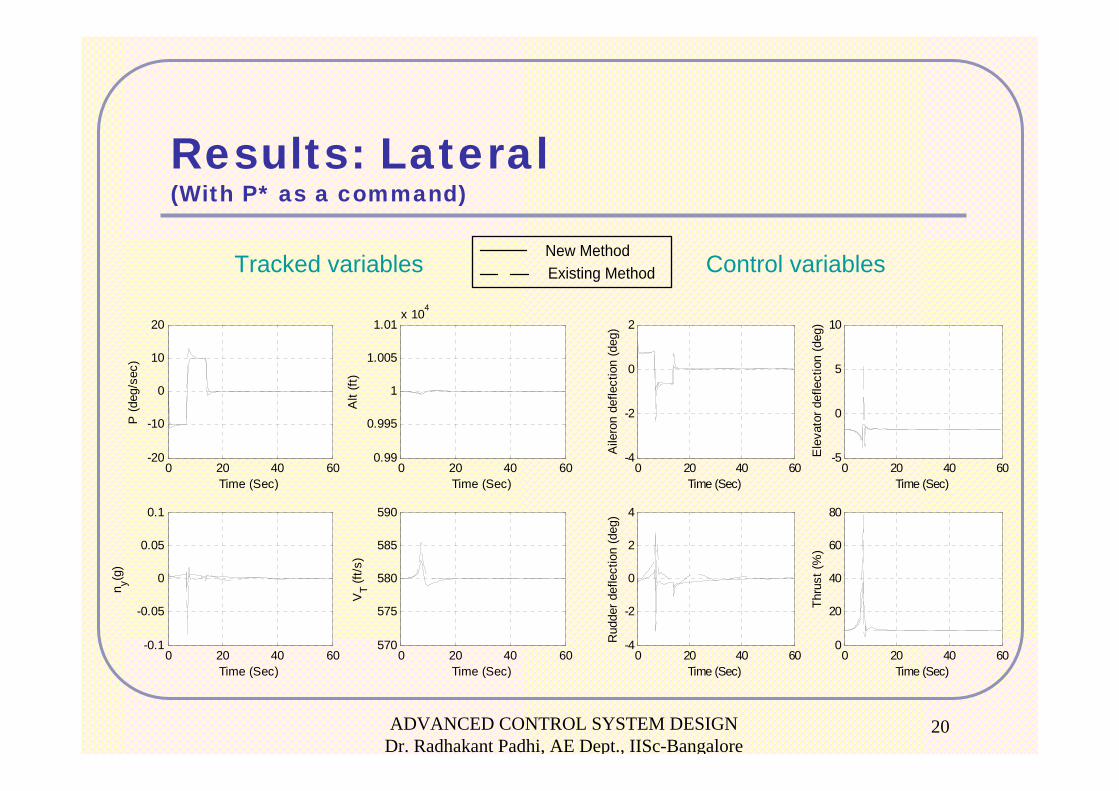
20
Tracked variables
Results: Lateral(With P* as a command)
0 20 40 60-20
-10
0
10
20
Time (Sec)
P (d
eg/s
ec)
0 20 40 600.99
0.995
1
1.005
1.01x 10⁴
Time (Sec)
Alt
(ft)
0 20 40 60-0.1
-0.05
0
0.05
0.1
Time (Sec)
n y(g)
0 20 40 60570
575
580
585
590
Time (Sec)
VT (f
t/s)
Control variables
0 20 40 600
20
40
60
80
Time (Sec)
Thru
st (%
)
0 20 40 60-4
-2
0
2
Time (Sec)
Aile
ron
defle
ctio
n (d
eg)
0 20 40 60-5
0
5
10
Time (Sec)
Ele
vato
r def
lect
ion
(deg
)
0 20 40 60-4
-2
0
2
4
Time (Sec)
Rud
der d
efle
ctio
n (d
eg)
New MethodExisting Method
ADVANCED CONTROL SYSTEM DESIGN Dr. Radhakant Padhi, AE Dept., IISc-Bangalore
21
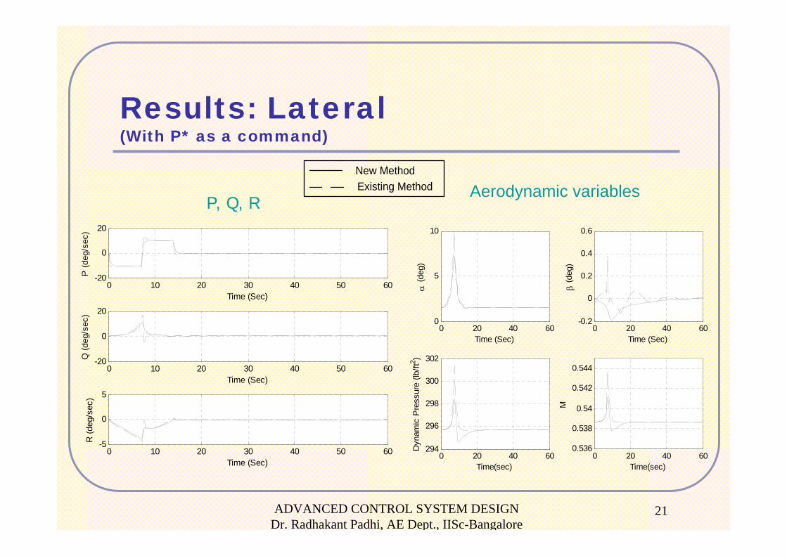
Aerodynamic variables
Results: Lateral(With P* as a command)
0 10 20 30 40 50 60-20
0
20
Time (Sec)
P (d
eg/s
ec)
0 10 20 30 40 50 60-20
0
20
Time (Sec)
Q (d
eg/s
ec)
0 10 20 30 40 50 60-5
0
5
Time (Sec)
R (d
eg/s
ec)
0 20 40 600
5
10
Time (Sec)
α (d
eg)
0 20 40 60-0.2
0
0.2
0.4
0.6
Time (Sec)
β (d
eg)
0 20 40 60294
296
298
300
302
Time(sec)
Dyn
amic
Pre
ssur
e (lb
/ft2 )
0 20 40 600.536
0.538
0.54
0.542
0.544
Time(sec)
M
New MethodExisting Method
P, Q, R
ADVANCED CONTROL SYSTEM DESIGN Dr. Radhakant Padhi, AE Dept., IISc-Bangalore
22
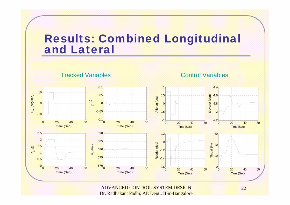
Results: Combined Longitudinal and Lateral
Tracked Variables Control Variables
0 20 40 60
-10
0
10
Time (Sec)
Pw
(deg
/sec
)
0 20 40 60-0.1
-0.05
0
0.05
0.1
Time (Sec)
n y (g)
0 20 40 600
0.5
1
1.5
2
2.5
Time (Sec)
n z (g)
0 20 40 60570
575
580
585
590
Time (Sec)
VT (f
t/s)
0 20 40 600
20
40
60
Time (Sec)
Thru
st (%
)
0 20 40 60-1
-0.5
0
0.5
1
Time (Sec)
Aile
ron
(deg
)
0 20 40 60-2.2
-2
-1.8
-1.6
-1.4
Time (Sec)
Ele
vato
r (de
g)
0 20 40 60-0.6
-0.4
-0.2
0
0.2
Time (Sec)
Rud
der (
deg)
ADVANCED CONTROL SYSTEM DESIGN Dr. Radhakant Padhi, AE Dept., IISc-Bangalore
23
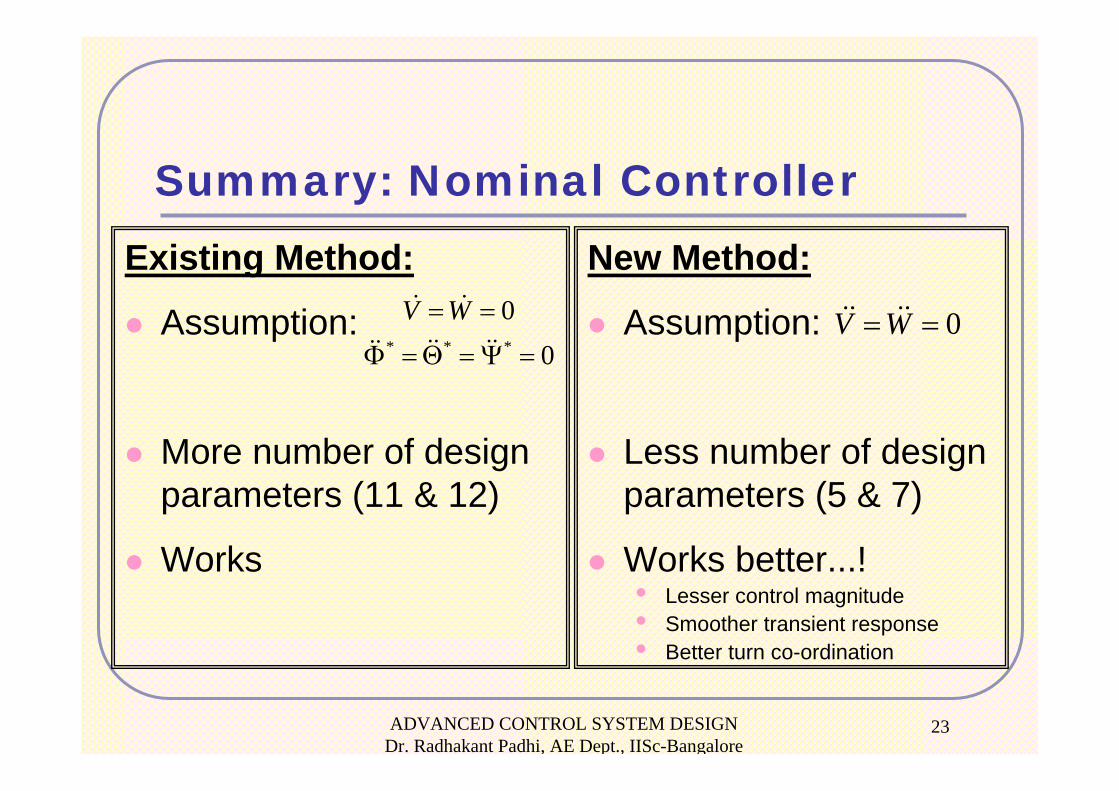
Summary: Nominal ControllerExisting Method:
Assumption:
More number of design parameters (11 & 12)
Works
New Method:
Assumption:
Less number of design parameters (5 & 7)
Works better...!• Lesser control magnitude• Smoother transient response• Better turn co-ordination
* * *
00
V W= =
Φ = Θ = Ψ =0V W= =
Neuro-Adaptive Control Designfor Enhanced Robustness
Indian Institute of Science, Bangalore
ADVANCED CONTROL SYSTEM DESIGN Dr. Radhakant Padhi, AE Dept., IISc-Bangalore
25
Objective:
To increase the robustness of the
“Nominal Controller” with respect to
parameter and/or modeling
uncertainties.
ADVANCED CONTROL SYSTEM DESIGN Dr. Radhakant Padhi, AE Dept., IISc-Bangalore
26
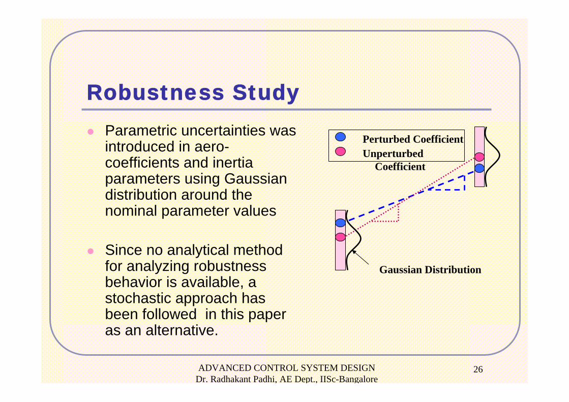
Robustness StudyParametric uncertainties was introduced in aero-coefficients and inertia parameters using Gaussian distribution around the nominal parameter values
Since no analytical method for analyzing robustness behavior is available, a stochastic approach has been followed in this paper as an alternative.
Gaussian Distribution
Perturbed CoefficientUnperturbed
Coefficient
ADVANCED CONTROL SYSTEM DESIGN Dr. Radhakant Padhi, AE Dept., IISc-Bangalore
27
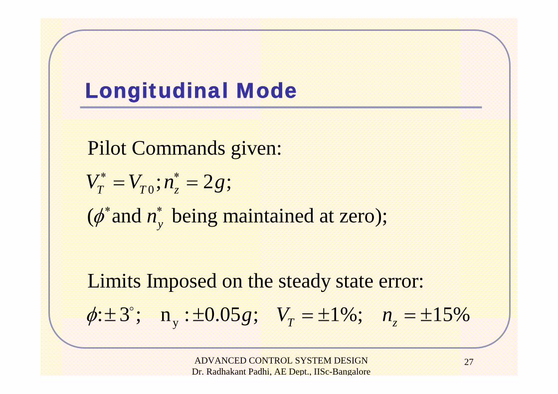
Longitudinal Mode
0
y
Pilot Commands given: ; 2 ;
( and being maintained at zero);
Limits Imposed on the steady state error:: 3 ; n : 0.05 ; 1%; 15%
T T z
y
T z
V V n g
n
g V n
φ
φ
∗ ∗
∗ ∗
= =
± ± = ± = ±
ADVANCED CONTROL SYSTEM DESIGN Dr. Radhakant Padhi, AE Dept., IISc-Bangalore
28
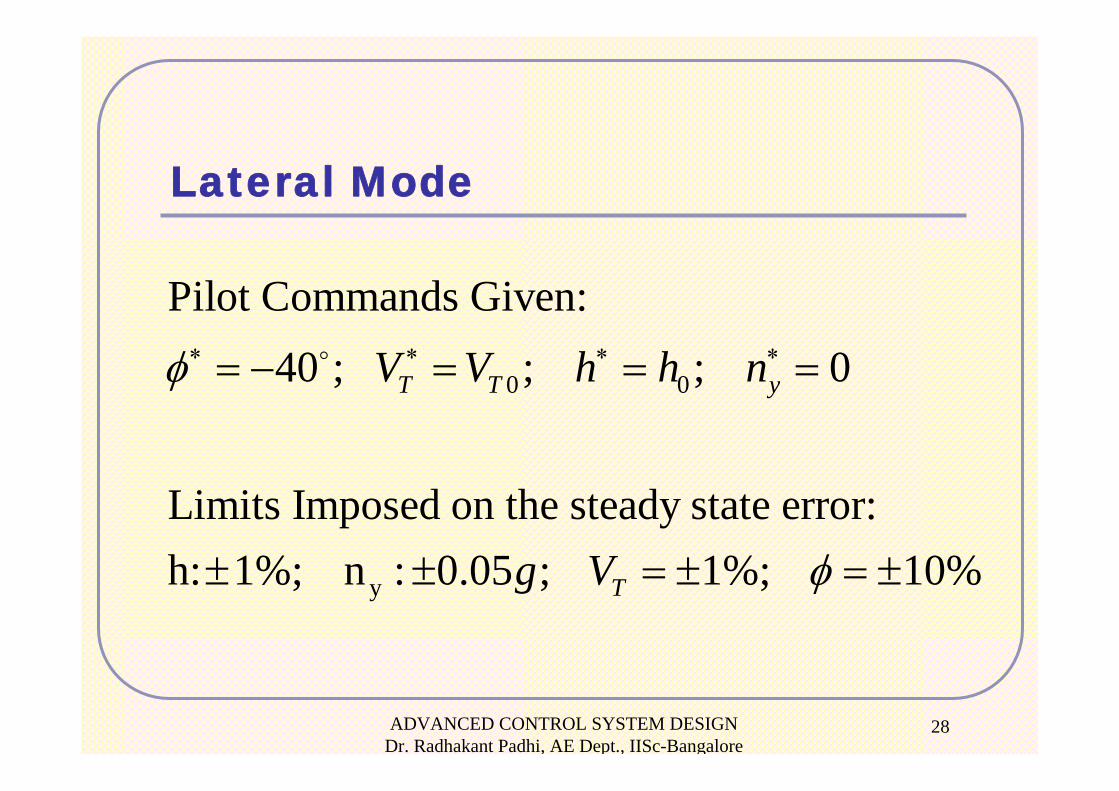
Lateral Mode
0 0
y
Pilot Commands Given: 40 ; ; ; 0
Limits Imposed on the steady state error:h: 1%; n : 0.05 ; 1%; 10%
T T y
T
V V h h n
g V
φ
φ
∗ ∗ ∗ ∗= − = = =
± ± = ± = ±
ADVANCED CONTROL SYSTEM DESIGN Dr. Radhakant Padhi, AE Dept., IISc-Bangalore
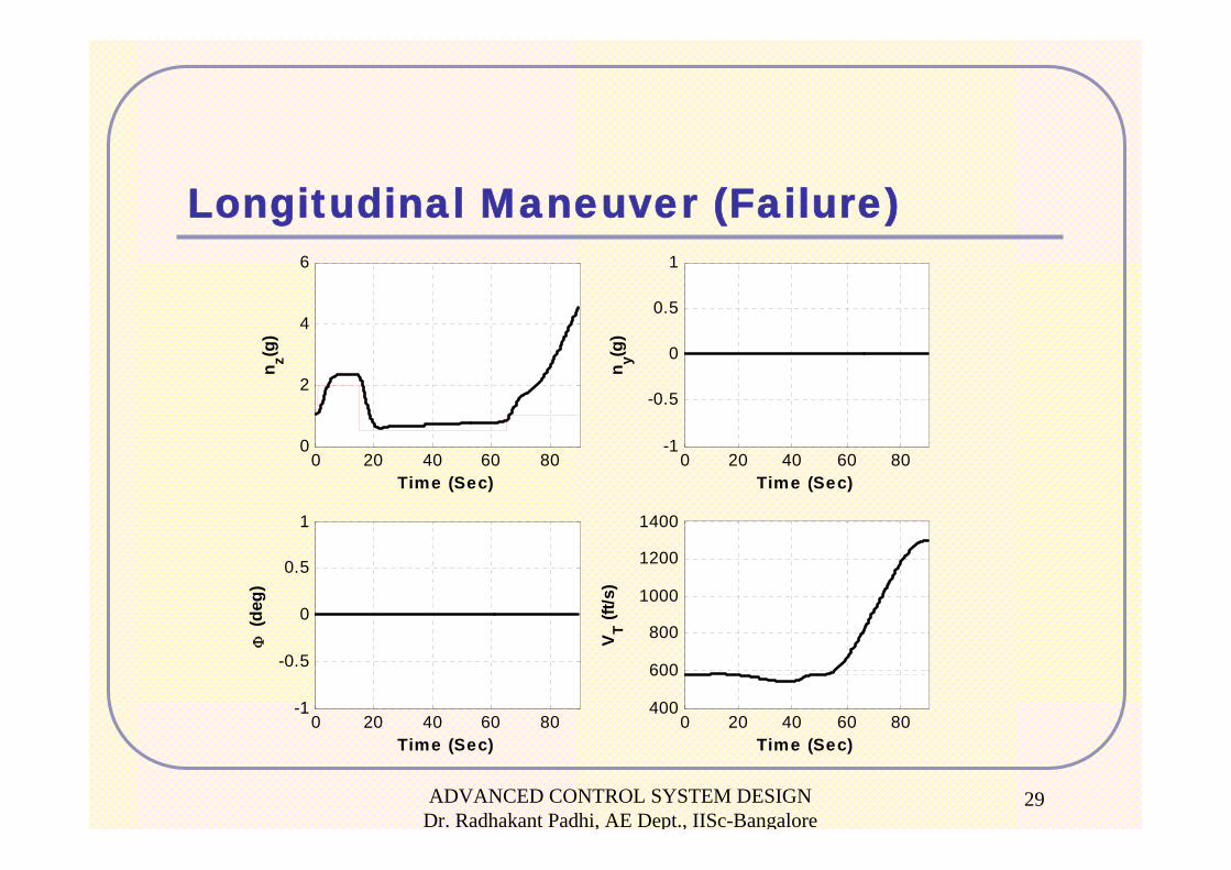
29
Longitudinal Maneuver (Failure)
0 20 40 60 800
2
4
6
Time (Sec)
n z(g)
0 20 40 60 80-1
-0.5
0
0.5
1
Time (Sec)
n y(g)
0 20 40 60 80-1
-0.5
0
0.5
1
Time (Sec)
Φ (d
eg)
0 20 40 60 80400
600
800
1000
1200
1400
Time (Sec)
VT (f
t/s)

ADVANCED CONTROL SYSTEM DESIGN Dr. Radhakant Padhi, AE Dept., IISc-Bangalore
30
Longitudinal Maneuver (Failure)
0 20 40 60 800
20
40
60
80
100
Time (Sec)
Thru
st (%
)
0 20 40 60 80-1
-0.5
0
0.5
1
Time (Sec)
Aile
ron
defle
ctio
n (d
eg)
0 20 40 60 80-2.2
-2
-1.8
-1.6
-1.4
Tim e (S e c )
Ele
vato
r def
lect
ion
(deg
)
0 20 40 60 80-1
-0.5
0
0.5
1
Time (Sec)
Rud
der
defle
ctio
n (d
eg)
ADVANCED CONTROL SYSTEM DESIGN Dr. Radhakant Padhi, AE Dept., IISc-Bangalore
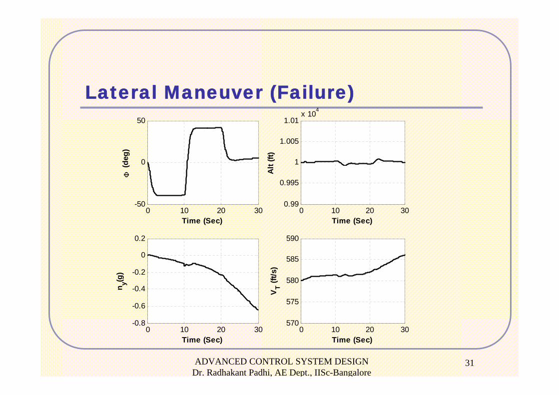
31
Lateral Maneuver (Failure)
0 10 20 30-50
0
50
Time (Sec)
Φ (d
eg)
0 10 20 300.99
0.995
1
1.005
1.01x 10⁴
Time (Sec)
Alt
(ft)
0 10 20 30-0.8
-0.6
-0.4
-0.2
0
0.2
Time (Sec)
n y(g)
0 10 20 30570
575
580
585
590
Time (Sec)
VT (f
t/s)
ADVANCED CONTROL SYSTEM DESIGN Dr. Radhakant Padhi, AE Dept., IISc-Bangalore
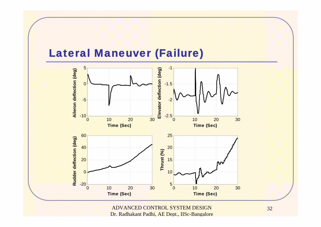
32
Lateral Maneuver (Failure)
0 10 20 305
10
15
20
25
Time (Sec)
Thru
st (%
)
0 10 20 30-10
-5
0
5
Time (Sec)
Aile
ron
defle
ctio
n (d
eg)
0 10 20 30-2.5
-2
-1.5
-1
Time (Sec)
Ele
vato
r de
flect
ion
(deg
)
0 10 20 30-20
0
20
40
60
Time (Sec)
Rud
der
defle
ctio
n (d
eg)
ADVANCED CONTROL SYSTEM DESIGN Dr. Radhakant Padhi, AE Dept., IISc-Bangalore
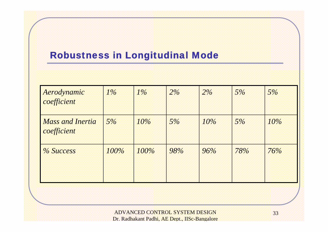
33
Robustness in Longitudinal Mode
76%78%96%98%100%100%% Success
10%5%10%5%10%5%Mass and Inertia coefficient
5%5%2%2%1%1%Aerodynamic coefficient
ADVANCED CONTROL SYSTEM DESIGN Dr. Radhakant Padhi, AE Dept., IISc-Bangalore
34
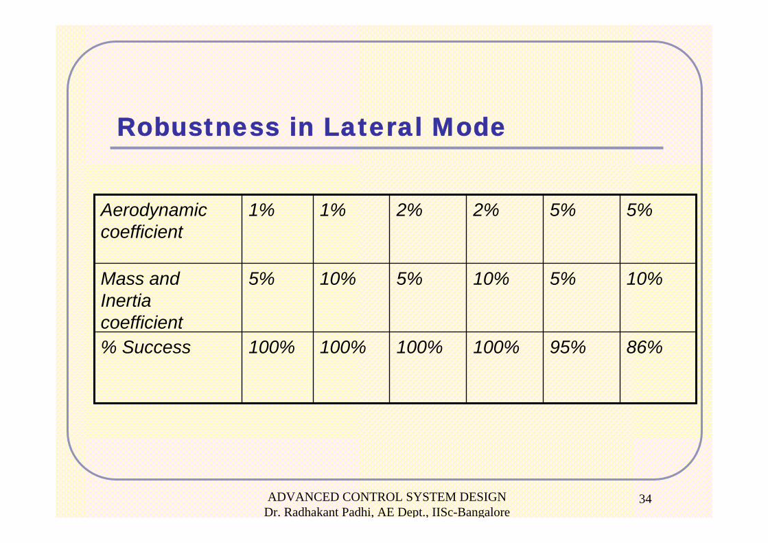
Robustness in Lateral Mode
86%95%100%100%100%100%% Success
10%5%10%5%10%5%Mass and Inertia coefficient
5%5%2%2%1%1%Aerodynamic coefficient
ADVANCED CONTROL SYSTEM DESIGN Dr. Radhakant Padhi, AE Dept., IISc-Bangalore
35
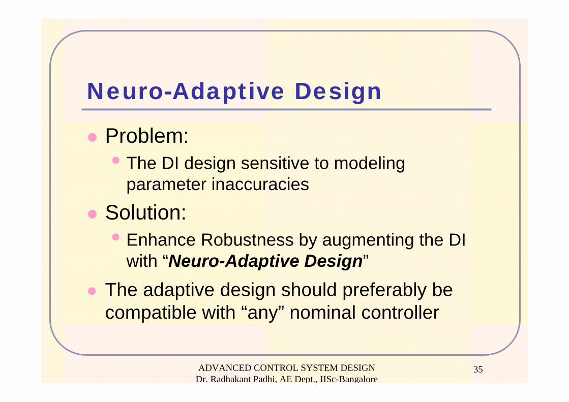
Neuro-Adaptive Design
Problem: • The DI design sensitive to modeling
parameter inaccuracies
Solution: • Enhance Robustness by augmenting the DI
with “Neuro-Adaptive Design”
The adaptive design should preferably be compatible with “any” nominal controller
ADVANCED CONTROL SYSTEM DESIGN Dr. Radhakant Padhi, AE Dept., IISc-Bangalore
36
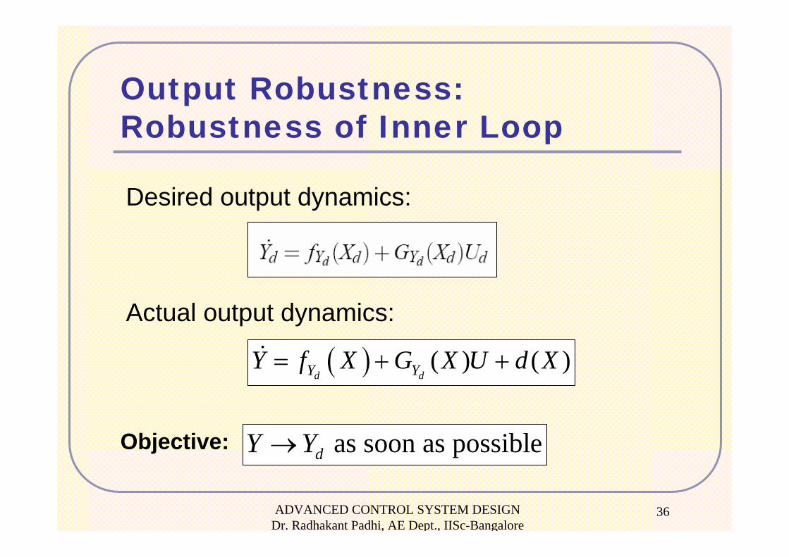
Desired output dynamics:
Output Robustness:Robustness of Inner Loop
Actual output dynamics:
as soon as possibledY Y→Objective:
( ) ( ) ( )d dY YY f X G X U d X= + +
ADVANCED CONTROL SYSTEM DESIGN Dr. Radhakant Padhi, AE Dept., IISc-Bangalore
37
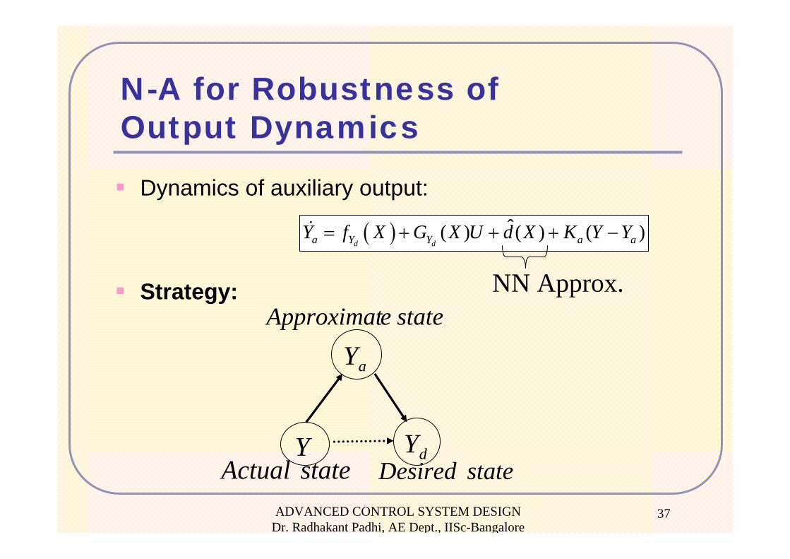
Strategy:
aY
Y dYstateDesiredstateActual
stateeApproximat
N-A for Robustness of Output Dynamics
Dynamics of auxiliary output:
( ) ˆ( ) ( ) ( )d da Y Y a aY f X G X U d X K Y Y= + + + −
NN Approx.
ADVANCED CONTROL SYSTEM DESIGN Dr. Radhakant Padhi, AE Dept., IISc-Bangalore
38
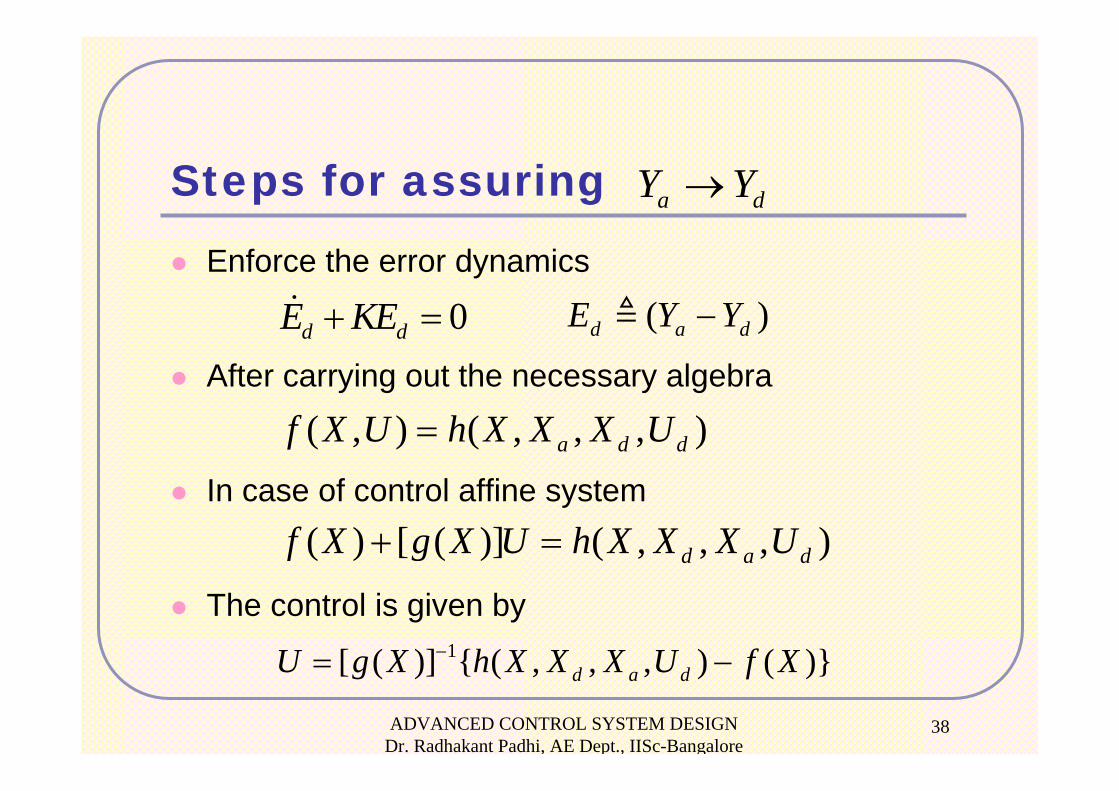
Steps for assuring a dY Y→
0d dE KE+ = ( )d a dE Y Y−Enforce the error dynamics
After carrying out the necessary algebra
In case of control affine system
The control is given by
( , ) ( , , , ) a d df X U h X X X U=
( ) [ ( )] ( , , , )d a df X g X U h X X X U+ =
1[ ( )] { ( , , , ) ( )}d a dU g X h X X X U f X−= −
ADVANCED CONTROL SYSTEM DESIGN Dr. Radhakant Padhi, AE Dept., IISc-Bangalore
39
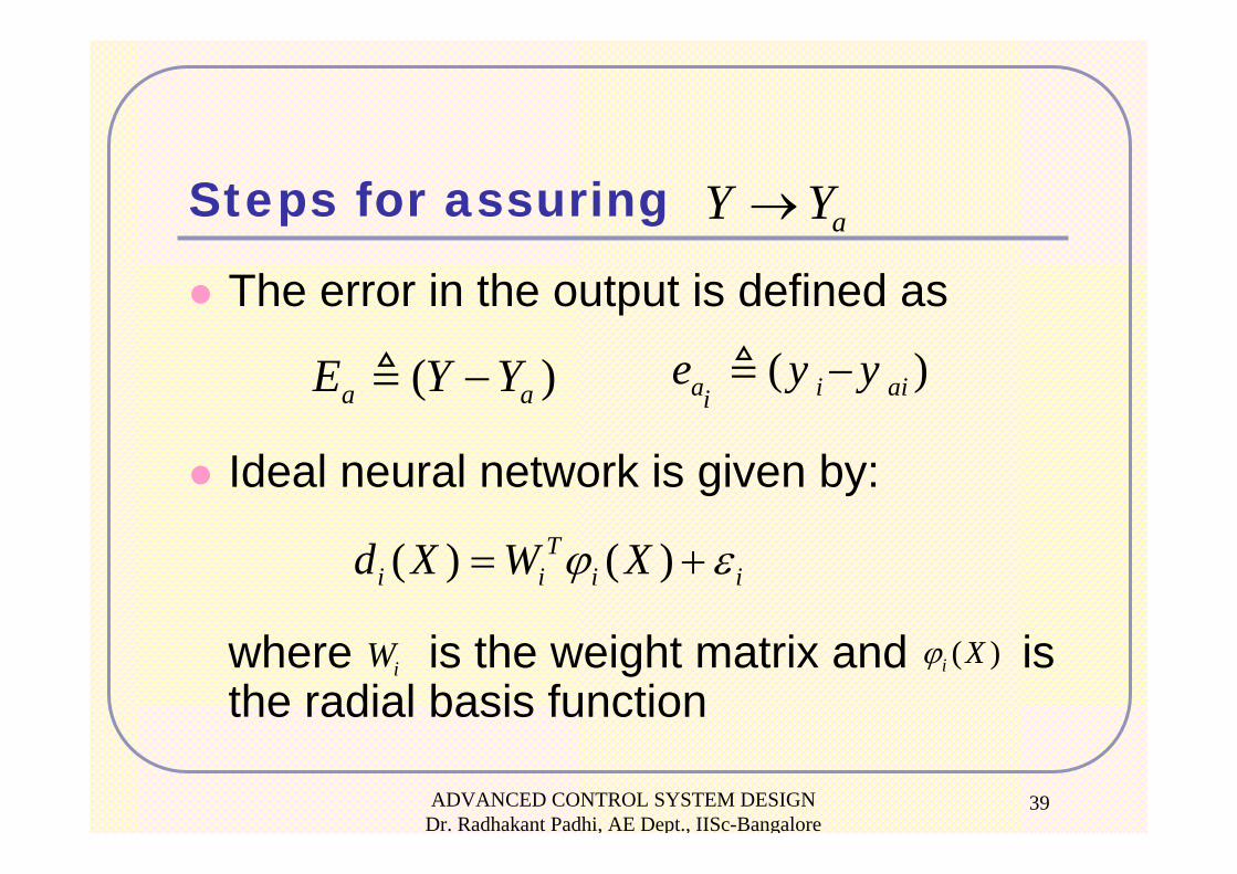
Steps for assuring
The error in the output is defined as
Ideal neural network is given by:
where is the weight matrix and is the radial basis function
aY Y→
( )a aE Y Y− ( )a i aiie y y−
( ) ( )Ti i i id X W Xϕ ε= +
iW ( )i Xϕ
ADVANCED CONTROL SYSTEM DESIGN Dr. Radhakant Padhi, AE Dept., IISc-Bangalore
40
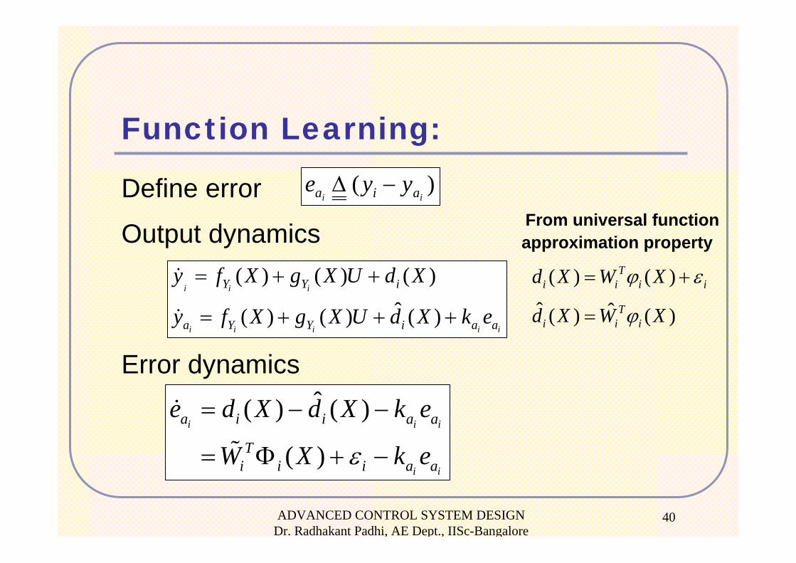
Function Learning:
Define error
Output dynamics
)(ii aia yye −Δ
( ) ( ) ( )ˆ( ) ( ) ( )
i i i
i i i i i
Y Y i
a Y Y i a a
y f X g X U d X
y f X g X U d X k e
= + +
= + + +
ˆ( ) ( )
( )i i i
i i
a i i a a
Ti i i a a
e d X d X k e
W X k eε
= − −
= Φ + −
( ) ( )Ti i i id X W Xϕ ε= +
From universal function approximation property
ˆ ˆ( ) ( )Ti i id X W Xϕ=
Error dynamics
ADVANCED CONTROL SYSTEM DESIGN Dr. Radhakant Padhi, AE Dept., IISc-Bangalore
41
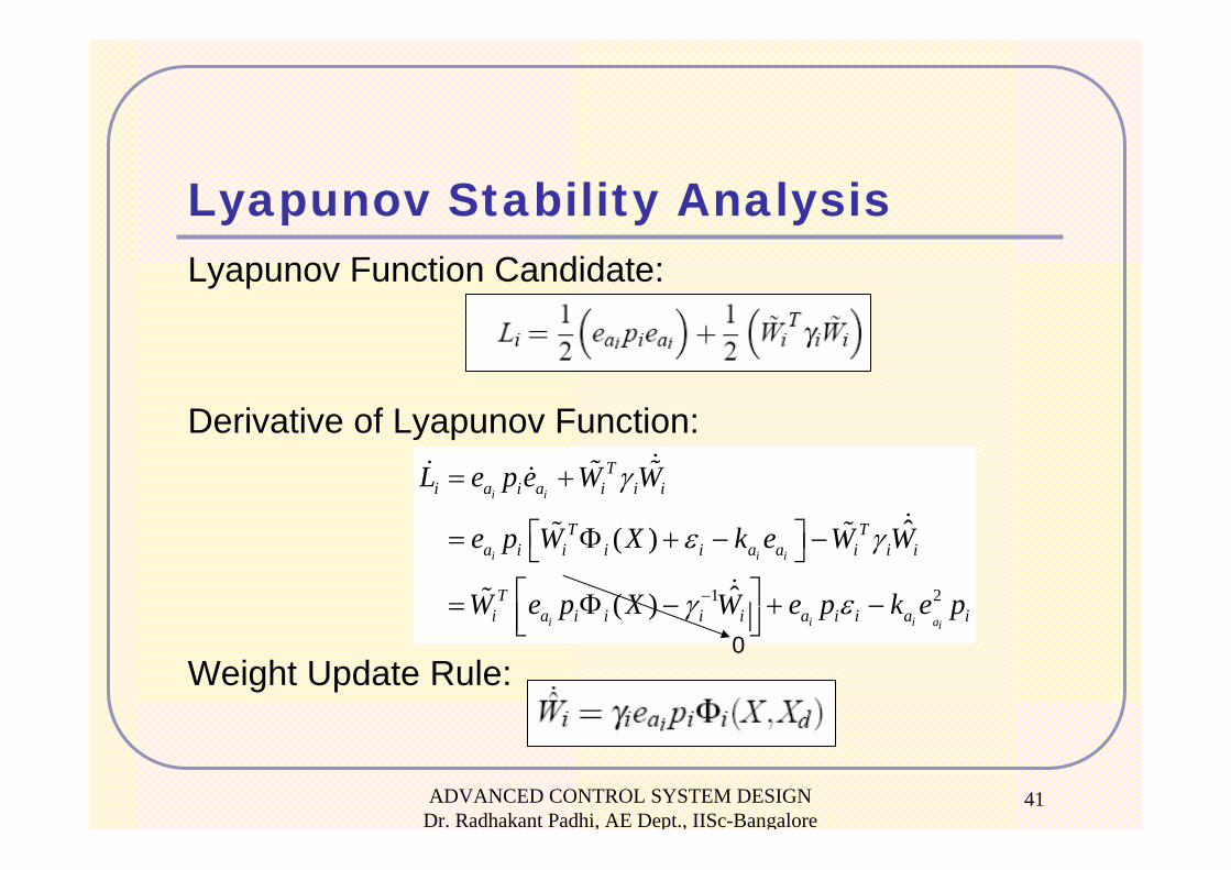
Lyapunov Stability Analysis
1 2
ˆ( )
ˆ( )
i i
i i i
i i i ai
Ti a i a i i i
T Ta i i i i a a i i i
Ti a i i i i a i i a i
L e p e W W
e p W X k e W W
W e p X W e p k e p
γ
ε γ
γ ε−
= +
⎡ ⎤= Φ + − −⎣ ⎦⎡ ⎤= Φ − + −⎢ ⎥⎣ ⎦
Lyapunov Function Candidate:
Derivative of Lyapunov Function:
Weight Update Rule:0
ADVANCED CONTROL SYSTEM DESIGN Dr. Radhakant Padhi, AE Dept., IISc-Bangalore
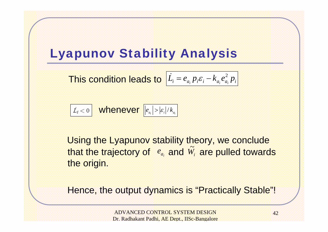
42
This condition leads to
whenever
Using the Lyapunov stability theory, we conclude that the trajectory of and are pulled towards the origin.
Hence, the output dynamics is “Practically Stable”!
/i ia i ae kε>
iaaiiai pekpeLiii
2−= ε
iae iW~
Lyapunov Stability Analysis
ADVANCED CONTROL SYSTEM DESIGN Dr. Radhakant Padhi, AE Dept., IISc-Bangalore
43
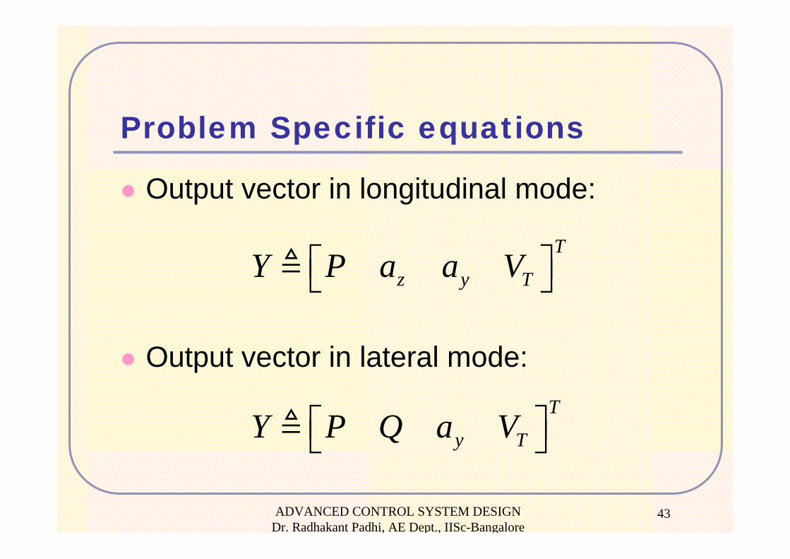
Problem Specific equations
Output vector in longitudinal mode:
Output vector in lateral mode:
T
z y TY P a a V⎡ ⎤⎣ ⎦
T
y TY P Q a V⎡ ⎤⎣ ⎦
ADVANCED CONTROL SYSTEM DESIGN Dr. Radhakant Padhi, AE Dept., IISc-Bangalore
44
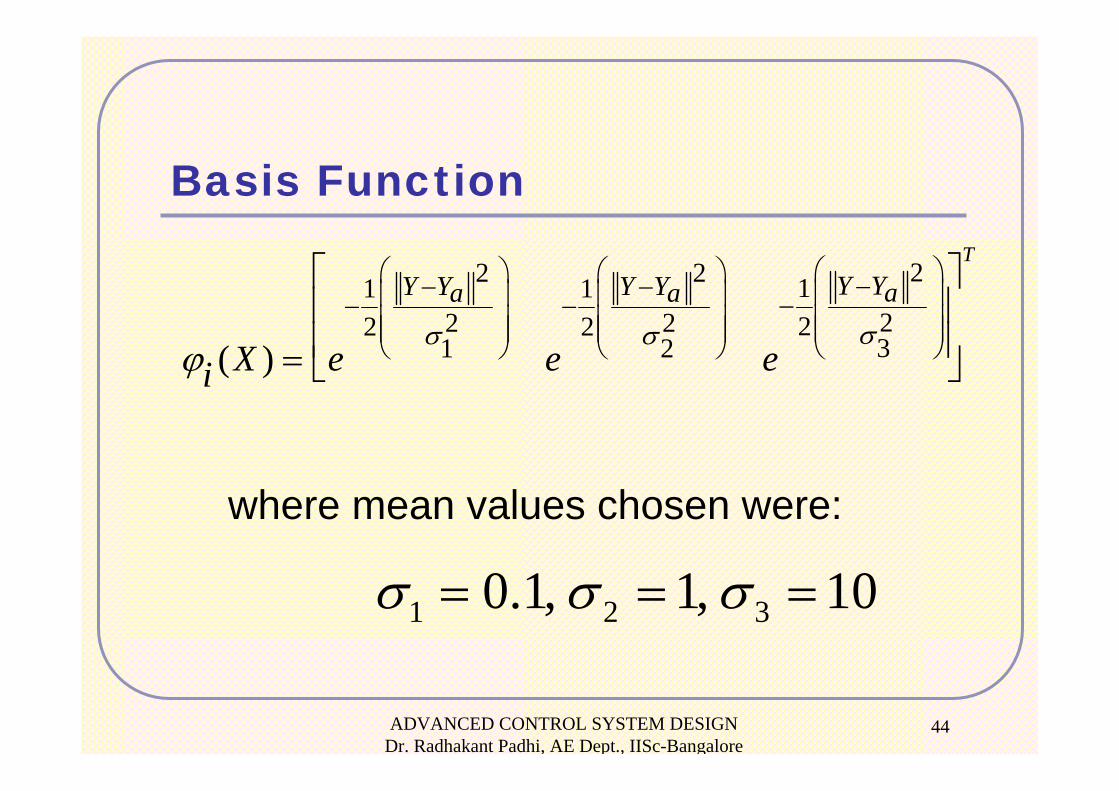
Basis Function
where mean values chosen were:
22 2 11 122 2 22 231 2( )
TY YY Y Y Y aa a
X e e eiσσ σ
ϕ
⎛ ⎞⎛ ⎞ ⎛ ⎞ −− − ⎜ ⎟⎜ ⎟ ⎜ ⎟ −− − ⎜ ⎟⎜ ⎟ ⎜ ⎟⎜ ⎟ ⎜ ⎟ ⎜ ⎟⎝ ⎠ ⎝ ⎠ ⎝ ⎠
⎡ ⎤⎢ ⎥⎢ ⎥= ⎣ ⎦
1 2 30.1, 1, 10σ σ σ= = =
ADVANCED CONTROL SYSTEM DESIGN Dr. Radhakant Padhi, AE Dept., IISc-Bangalore
45
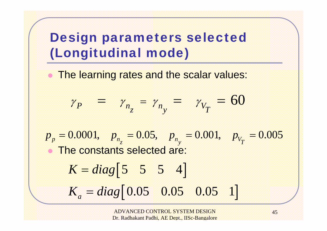
Design parameters selected (Longitudinal mode)
The learning rates and the scalar values:
The constants selected are:0.0001, 0.05, 0.001, 0.005p n n Vz y T
p p p p= = = =
60P n n Vz y Tγ γ γ γ== = =
[ ][ ]5 5 5 4
0.05 0.05 0.05 1a
K diag
K diag
=
=
ADVANCED CONTROL SYSTEM DESIGN Dr. Radhakant Padhi, AE Dept., IISc-Bangalore
46
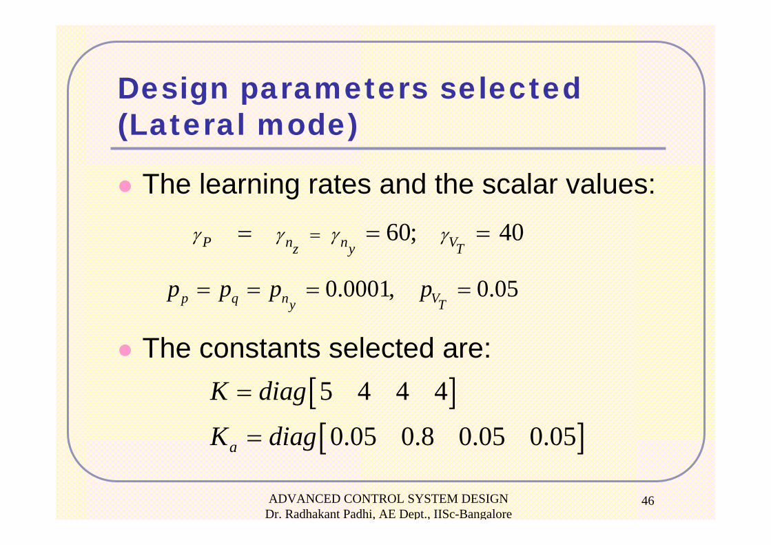
Design parameters selected (Lateral mode)
The learning rates and the scalar values:
The constants selected are:
60; 40P n n Vz y Tγ γ γ γ== = =
0.0001, 0.05p q n Vy Tp p p p= = = =
[ ][ ]5 4 4 4
0.05 0.8 0.05 0.05a
K diag
K diag
=
=
ADVANCED CONTROL SYSTEM DESIGN Dr. Radhakant Padhi, AE Dept., IISc-Bangalore
47
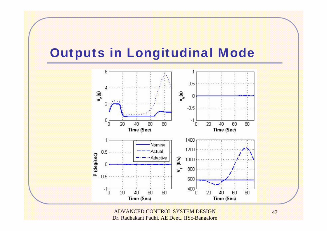
Outputs in Longitudinal Mode
ADVANCED CONTROL SYSTEM DESIGN Dr. Radhakant Padhi, AE Dept., IISc-Bangalore
48
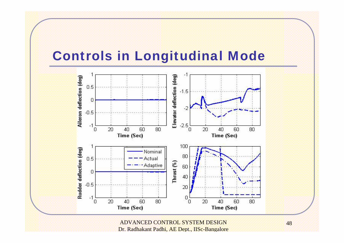
Controls in Longitudinal Mode
ADVANCED CONTROL SYSTEM DESIGN Dr. Radhakant Padhi, AE Dept., IISc-Bangalore
49
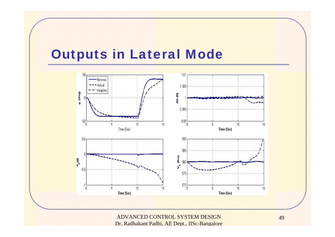
Outputs in Lateral Mode
ADVANCED CONTROL SYSTEM DESIGN Dr. Radhakant Padhi, AE Dept., IISc-Bangalore
50
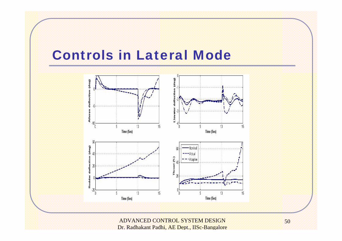
Controls in Lateral Mode
ADVANCED CONTROL SYSTEM DESIGN Dr. Radhakant Padhi, AE Dept., IISc-Bangalore
51
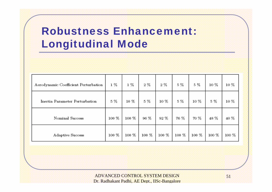
Robustness Enhancement:Longitudinal Mode
ADVANCED CONTROL SYSTEM DESIGN Dr. Radhakant Padhi, AE Dept., IISc-Bangalore
52
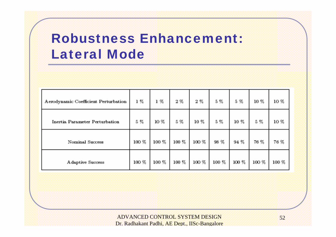
Robustness Enhancement:Lateral Mode
ADVANCED CONTROL SYSTEM DESIGN Dr. Radhakant Padhi, AE Dept., IISc-Bangalore
53
SummaryNominal control design has been carried out using “dynamic inversion” (the new method shows remarkable improvement in performance!)
The nominal design has been augmented with “neuro-adaptive design” for improvement in robustness.
Simulation Results• Tracking performance is very good
• Enhancement of robustness is substantial
ADVANCED CONTROL SYSTEM DESIGN Dr. Radhakant Padhi, AE Dept., IISc-Bangalore
54
ReferencesRadhakant Padhi, Narayan P. Rao, Siddharth Goyal and Abha Tripathi, “A Model-Following Neuro-Adaptive Approach for Robust Control of High Performance Aircrafts”, Automatic Control in Aerospace, Vol. 3, No. 1, May 2010.Radhakant Padhi and S. N. Balakrishnan, “Implementation of Pilot Commands in Aircraft Control: A New Dynamic Inversion Approach”, AIAA Conference on Guidance Navigation and Control, 2003, Austin, TX, USA. Radhakant Padhi, Nishant Unnikrishnan and S. N. Balakrishnan, “Model Following Neuro-Adaptive Control Design for Non-square, Non-affine Nonlinear Systems”, IET Control Theory and Applications, Vol. 1 (6), Nov 2007, pp.1650-1661.
ADVANCED CONTROL SYSTEM DESIGN Dr. Radhakant Padhi, AE Dept., IISc-Bangalore
55