Embed Size (px)
Citation preview
Robust extraction of image correspondences exploiting the image scene geometry and
approximate camera orientation
Bashar Alsadika,c, Fabio Remondinob, Fabio Mennab, Markus Gerkea, George Vosselmana
a University of Twente, ITC Faculty, EOS department, Enschede, The Netherlands – (alsadik, gerke, vosselman)@itc.nl
b Bruno Kessler Foundation FBK, 3D Optical Metrology unit, Trento, Italy – (remondino,fmenna)@fbk.eu c University of Baghdad, College of Engineering, Surveying Department, Baghdad, Iraq
Commission V, WG V/4
KEY WORDS: IBM - Bundle adjustment - SIFT - 3D image - spanning tree
ABSTRACT:
Image-based modeling techniques are an important tool for producing 3D models in a practical and cost effective manner. Accurate
image-based models can be created as long as one can retrieve precise image calibration and orientation information which is
nowadays performed automatically in computer vision and photogrammetry. The first step for orientation is to have sufficient
correspondences across the captured images. Keypoint descriptors like SIFT or SURF are a successful approach for finding these
correspondences. The extraction of precise image correspondences is crucial for the subsequent image orientation and image
matching steps. Indeed there are still many challenges especially with wide-baseline image configuration. After the extraction of a
sufficient and reliable set of image correspondences, a bundle adjustment is used to retrieve the image orientation parameters.
In this paper, a brief description of our previous work on automatic camera network design is initially reported. This semi-automatic
procedure results in wide-baseline high resolution images covering an object of interest, and including approximations of image
orientations, a rough 3D object geometry and a matching matrix indicating for each image its matching mates. The main part of this
paper will describe the subsequent image matching where the pre-knowledge on the image orientations and the pre-created rough 3D
model of the study object is exploited. Ultimately the matching information retrieved during that step will be used for a precise
bundle block adjustment.
Since we defined the initial image orientation in the design of the network, we can compute the matching matrix prior to image
matching of high resolution images. For each image involved in several pairs that is defined in the matching matrix, we detect the
corners or keypoints and then transform them into the matching images by using the designed orientation and initial 3D model.
Moreover, a window is defined for each corner and its initial correspondence in the matching images. A SIFT or SURF matching is
implemented between every matching window to find the homologous points. This is followed by Least Square Matching LSM to
refine the correspondences for a sub-pixel localization and to avoid inaccurate matches. Image matching is followed by a bundle
adjustment to orient the images automatically to finally have a sparse 3D model. We used the commercial software Photomodeler
Scanner 2010 for implementing the bundle adjustment since it reports a number of accuracy indices which are necessary for the
evaluation purposes. The experimental test of comparing the automated image matching of four pre-designed streopairs shows that
our approach can provide a high accuracy and effective orientation when compared to the results of commercial and open source
software which does not exploit the pre-knowledge about the scene.
1. INTRODUCTION
Image-based modeling (IBM) (Remondino and El-Hakim,
2006) is an important tool nowadays for realistic 3D modeling
and other applications in close range photogrammetry (CRP)
and computer vision (CV). One crucial step within IBM is the
image network planning and subsequent image orientation, or
bundle adjustment. The following paper is concerned with those
tasks. Today, different software is available for performing the
image orientation task automatically, either commercial like
Photomodeler (PhotoModeler, 2009) and Photoscan (Photoscan,
2011) or open-source like Bundler (Snavely, 2010), MICMAC
(Pierrot-Deseilligny, 2012) and VSfM (Wu, 2012). However,
there is no guarantee about the correct results and often the
reliability is very low (Remondino et al., 2012) especially in the
case of large datasets, wide baseline configurations,
illumination changes, or when repetitive pattern and
homogenous texture areas exist.
Image orientation can be achieved more reliably when certain
information is available like initial camera exterior and interior
orientation parameters, image overlapping information and
information about the object geometry and structure.
Accordingly, the first demand of detecting image points and
matching them with other correspondences in other images
represents the most challenging tasks in the whole procedure
(Remondino et al., 2012; Yang and Yuille, 1995) Matching is
also a time dependent operation especially when the captured
images are:
- - of high resolution (HR), which is the case nowadays even with
consumer compact cameras or smartphones.
- - arranged in sparse block where the computation cost according
to Barazzetti et al. (2010) is with a combination of
images
The paper will address those issues by a consequent exploitation
of the knowledge about scene geometry and approximate
camera positions. In Alsadik et al. (2013) an approach for a
fully automatic camera network planning tool is described.
Starting from a video capture of the object of interest, such as a
building or a statue, and using established shape-from-motion
techniques, a simple 3D model is created. Based on this model,
International Archives of the Photogrammetry, Remote Sensing and Spatial Information Sciences, Volume XL-5/W1, 20133D-ARCH 2013 - 3D Virtual Reconstruction and Visualization of Complex Architectures, 25 – 26 February 2013, Trento, Italy
1
the optimal camera locations for high resolution images are
derived, where optimal refers to (i) retrieving a maximum point
accuracy and (ii) keep the number of images at a minimum to
reduce computation time. In a subsequent step, the camera
operator is guided to those optimal places and asked to take the
high resolution images (cf. section 2.1 below).
The paper continues along those research lines. Since the
approximate orientations of high resolution images and the
scene geometry are known, that knowledge is exploited for the
task of correspondences matching and final image orientation,
including bundle adjustment. Especially the fact that for each
image its matching mates are known independently from actual
matching techniques is an advantage over other approaches,
such as presented in (Snavely et al., 2008). In those methods the
so-called matching tree is computed from a brute-force
matching (all images against all), because no pre-information
about image locations is available. Those techniques are not
only expensive in terms of computation time but also vulnerable
to problems of mismatches, e.g. resulting from repetitive
patterns or symmetries in building architecture (Kosecka and
Zhang, 2010), as shown in Fig.1.
Image matching is followed by a bundle adjustment to orient the
images automatically and to finally have a sparse 3D model. We
use the commercial software Photomodeler Scanner 2010
(PhotoModeler, 2009) for implementing the bundle adjustment
since it reports all the accuracy indices (quality and RMSE)
which are necessary for the evaluation purposes. However, open
source software might be used later in the bundle adjustment
task like SBA (Lourakis and Argyros, 2004) and APERO
(Pierrot-Deseilligny, 2012).
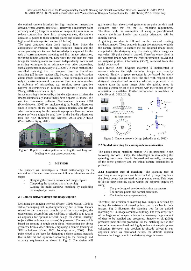
Figure 1. Repetitive texture patterns affecting the matching and
leading to wrong correspondences.
2. METHOD
The research will investigate a robust methodology for the
extraction of image correspondences following three successive
steps:
- Designing the camera network and image capture.
- Computing the spanning tree of matching.
- Guiding the multi windows matching by exploiting
the rough object model.
2.1 Camera network design and image capture
Designing the imaging network (Fraser, 1996; Mason, 1995) is
still a challenging task in photogrammetry due to many factors
related to the nature and complexity of the study object, the
used camera, accessibility and visibility. In Alsadik et al. (2013)
an approach for optimal network design for cultural heritage
objects (like buildings and statues) is presented. The method is
based on creating a rough point cloud representing the object
geometry from a video stream, employing a camera tracking or
SfM techniques (Nister, 2001; Pollefeys et al., 2004). This
point cloud is the base for designing a dense camera network
that is filtered and optimized according to the coverage and
accuracy requirement as shown in Fig. 2. The design will
guarantee at least three covering cameras per point beside a total
estimated error that fits the 3D modeling requirement.
Therefore, with the assumption of using a pre-calibrated
camera, the image interior and exterior orientation will be
initially known.
A guiding procedure is followed on the basis of creating
synthetic images. These synthetic images are important to guide
the camera operator to capture the pre-designed image poses
computed in the designing step. For each synthetic image an
equivalent 3D point cloud is created. Therefore every pixel in
the synthetic image will have the color information (RGB) and
an assigned position information (XYZ), retrieved from the
initial point cloud.
SIFT (Lowe, 2004) keypoint matching is implemented to
measure whether the high resolution images are correctly
captured. Finally, a space resection is performed for every
acquired image in order to check the shift with respect to the
designed orientation and to decide whether to proceed or to
capture again the same image. After the guiding setup is
finished, a complete set of HR images with their initial exterior
orientation is available. Further information is available in
(Alsadik et al., 2012, 2013).
Figure 2. Camera network design (Alsadik et al., 2012)
2.2 Guided matching for correspondences extraction
The guided image matching method will be presented in the
following sections. Firstly, the advantages in developing the
spanning tree of matching is discussed and secondly, the usage
of the scene geometry and the initial camera orientations is
presented.
2.2.1 Spanning tree of matching: The spanning tree of
matching in our approach can be extracted by projecting back
the object points that are used in the planning steps. This helps
to decide their visibility status within the captured images by
using:
- The pre-designed exterior orientation parameters.
- The surface points and normal directions.
- The interior camera parameters.
Therefore, the decision of matching two images is decided by
testing the existence of shared points that is visible in both
images. Fig. 3 illustrates the spanning tree for the guided
matching of 106 images around a building. The very dense tree
of the large set of images indicates the necessary huge amount
of data to be handled and processed. Snavely et al. (2008)
presented their skeletal procedure for the matching tree in the
case of a large, unordered and highly redundant sampled photo
collection. However, this problem is already solved in our
approach since, as mentioned before, the definite relation
between the image pairs in the designing stage is known.
International Archives of the Photogrammetry, Remote Sensing and Spatial Information Sciences, Volume XL-5/W1, 20133D-ARCH 2013 - 3D Virtual Reconstruction and Visualization of Complex Architectures, 25 – 26 February 2013, Trento, Italy
2
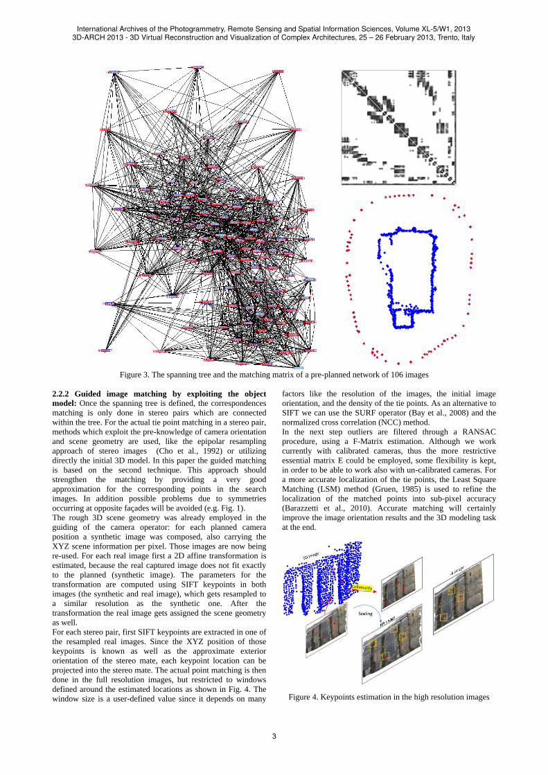
Figure 3. The spanning tree and the matching matrix of a pre-planned network of 106 images
2.2.2 Guided image matching by exploiting the object
model: Once the spanning tree is defined, the correspondences
matching is only done in stereo pairs which are connected
within the tree. For the actual tie point matching in a stereo pair,
methods which exploit the pre-knowledge of camera orientation
and scene geometry are used, like the epipolar resampling
approach of stereo images (Cho et al., 1992) or utilizing
directly the initial 3D model. In this paper the guided matching
is based on the second technique. This approach should
strengthen the matching by providing a very good
approximation for the corresponding points in the search
images. In addition possible problems due to symmetries
occurring at opposite façades will be avoided (e.g. Fig. 1).
The rough 3D scene geometry was already employed in the
guiding of the camera operator: for each planned camera
position a synthetic image was composed, also carrying the
XYZ scene information per pixel. Those images are now being
re-used. For each real image first a 2D affine transformation is
estimated, because the real captured image does not fit exactly
to the planned (synthetic image). The parameters for the
transformation are computed using SIFT keypoints in both
images (the synthetic and real image), which gets resampled to
a similar resolution as the synthetic one. After the
transformation the real image gets assigned the scene geometry
as well.
For each stereo pair, first SIFT keypoints are extracted in one of
the resampled real images. Since the XYZ position of those
keypoints is known as well as the approximate exterior
orientation of the stereo mate, each keypoint location can be
projected into the stereo mate. The actual point matching is then
done in the full resolution images, but restricted to windows
defined around the estimated locations as shown in Fig. 4. The
window size is a user-defined value since it depends on many
factors like the resolution of the images, the initial image
orientation, and the density of the tie points. As an alternative to
SIFT we can use the SURF operator (Bay et al., 2008) and the
normalized cross correlation (NCC) method.
In the next step outliers are filtered through a RANSAC
procedure, using a F-Matrix estimation. Although we work
currently with calibrated cameras, thus the more restrictive
essential matrix E could be employed, some flexibility is kept,
in order to be able to work also with un-calibrated cameras. For
a more accurate localization of the tie points, the Least Square
Matching (LSM) method (Gruen, 1985) is used to refine the
localization of the matched points into sub-pixel accuracy
(Barazzetti et al., 2010). Accurate matching will certainly
improve the image orientation results and the 3D modeling task
at the end.
Figure 4. Keypoints estimation in the high resolution images
International Archives of the Photogrammetry, Remote Sensing and Spatial Information Sciences, Volume XL-5/W1, 20133D-ARCH 2013 - 3D Virtual Reconstruction and Visualization of Complex Architectures, 25 – 26 February 2013, Trento, Italy
3
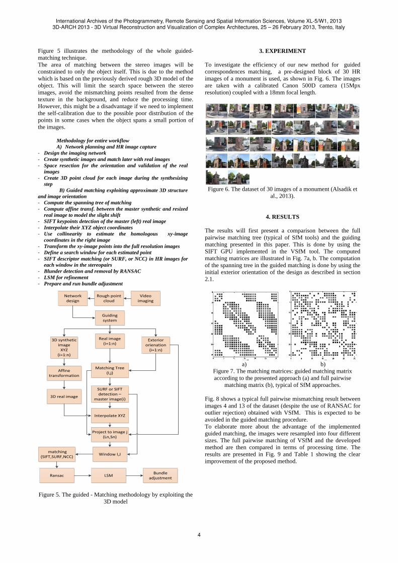
Figure 5 illustrates the methodology of the whole guided-
matching technique.
The area of matching between the stereo images will be
constrained to only the object itself. This is due to the method
which is based on the previously derived rough 3D model of the
object. This will limit the search space between the stereo
images, avoid the mismatching points resulted from the dense
texture in the background, and reduce the processing time.
However, this might be a disadvantage if we need to implement
the self-calibration due to the possible poor distribution of the
points in some cases when the object spans a small portion of
the images.
Methodology for entire workflow
A) Network planning and HR image capture
- Design the imaging network
- Create synthetic images and match later with real images
- Space resection for the orientation and validation of the real
images
- Create 3D point cloud for each image during the synthesizing
step
B) Guided matching exploiting approximate 3D structure
and image orientation
- Compute the spanning tree of matching
- Compute affine transf. between the master synthetic and resized
real image to model the slight shift
- SIFT keypoints detection of the master (left) real image
- Interpolate their XYZ object coordinates
- Use collinearity to estimate the homologous xy-image
coordinates in the right image
- Transform the xy-image points into the full resolution images
- Define a search window for each estimated point
- SIFT descriptor matching (or SURF, or NCC) in HR images for
each window in the stereopairs
- Blunder detection and removal by RANSAC
- LSM for refinement
- Prepare and run bundle adjustment
3D synthetic image
XYZ(i=1:n)
Real image(i=1:n)
Exterior orienation
(i=1:n)
Guiding system
Matching Tree (I,j)
SURF or SIFT detection –
master image(i)
Interpolate XYZ
Project to image j(Ln,Sn)
Affine transformation
3D real image
Window I,J matching
(SIFT,SURF,NCC)
Ransac LSMBundle
adjustment
Network design
Video imaging
Rough point cloud
Figure 5. The guided - Matching methodology by exploiting the
3D model
3. EXPERIMENT
To investigate the efficiency of our new method for guided
correspondences matching, a pre-designed block of 30 HR
images of a monument is used, as shown in Fig. 6. The images
are taken with a calibrated Canon 500D camera (15Mpx
resolution) coupled with a 18mm focal length.
Figure 6. The dataset of 30 images of a monument (Alsadik et
al., 2013).
4. RESULTS
The results will first present a comparison between the full
pairwise matching tree (typical of SfM tools) and the guiding
matching presented in this paper. This is done by using the
SIFT GPU implemented in the VSfM tool. The computed
matching matrices are illustrated in Fig. 7a, b. The computation
of the spanning tree in the guided matching is done by using the
initial exterior orientation of the design as described in section
2.1.
a) b)
Figure 7. The matching matrices: guided matching matrix
according to the presented approach (a) and full pairwise
matching matrix (b), typical of SfM approaches.
Fig. 8 shows a typical full pairwise mismatching result between
images 4 and 13 of the dataset (despite the use of RANSAC for
outlier rejection) obtained with VSfM. This is expected to be
avoided in the guided matching procedure.
To elaborate more about the advantage of the implemented
guided matching, the images were resampled into four different
sizes. The full pairwise matching of VSfM and the developed
method are then compared in terms of processing time. The
results are presented in Fig. 9 and Table 1 showing the clear
improvement of the proposed method.
International Archives of the Photogrammetry, Remote Sensing and Spatial Information Sciences, Volume XL-5/W1, 20133D-ARCH 2013 - 3D Virtual Reconstruction and Visualization of Complex Architectures, 25 – 26 February 2013, Trento, Italy
4
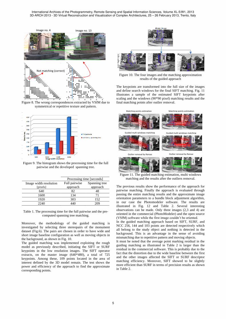
Figure 8. The wrong correspondences extracted by VSfM due to
symmetrical or repetitive texture and pattern.
Figure 9. The histogram shows the processing time for the full
pairwise and the developed spanning tree.
Processing time [seconds]
Image width resolution [pixels]
Full pairwise
approach
Spanning tree
approach
640 82 48
1600 134 71
1920 303 152
2240 440 209
Table 1. The processing time for the full pairwise and the pre-
computed spanning tree matching.
Moreover, the methodology of the guided matching is
investigated by selecting three stereopairs of the monument
dataset (Fig.6). The pairs are chosen in order to have wide and
short image baseline configuration as well as moving objects in
the background, as shown in Fig. 10.
The guided matching was implemented exploiting the rough
model as previously described, initiating the SIFT or SURF
keypoints in the low resolution images. The SIFT operator
extracts, on the master image (640*480), a total of 725
keypoints. Among these, 109 points located in the area of
interest defined by the 3D model remain. The test shows the
power and efficiency of the approach to find the approximate
corresponding points.
Figure 10. The four images and the matching approximation
results of the guided approach
The keypoints are transformed into the full size of the images
and define search windows for the final SIFT matching. Fig. 11
illustrates a sample of the estimated SIFT keypoints after
scaling and the windows (90*90 pixel) matching results and the
final matching points after outlier removal.
Figure 11. The guided matching estimation, multi windows
matching and the results after the outliers removal.
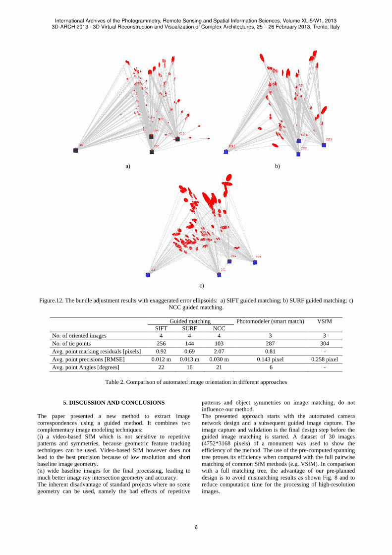
The previous results show the performance of the approach for
pairwise matching. Finally the approach is evaluated through
passing the entire matching results and the approximate image
orientation parameters to a bundle block adjustment algorithm,
in our case the Photomodeler software. The results are
illustrated in Fig. 12 and Table 2. Several interesting
observations can be made. Only three images (2,3 and 4) are
oriented in the commercial (PhotoModeler) and the open source
(VSfM) software while the first image couldn’t be oriented.
In the guided matching approach based on SIFT, SURF, and
NCC 256, 144 and 103 points are detected respectively which
all belong to the study object and nothing is detected in the
background. This is an advantage in the sense of avoiding
mismatching due to repetitive pattern and moving objects.
It must be noted that the average point marking residual in the
guiding matching as illustrated in Table 2 is larger than the
residual in the commercial software. This is probably due to the
fact that the distortion due to the wide baseline between the first
and the other images affected the SIFT or SURF descriptor
matching efficiency. Moreover, SIFT showed to be slightly
more efficient than SURF in terms of precision results as shown
in Table 2.
Image no. 4 Image no. 13
Not matching (correct)
GUIDED MULTI WINDOW MATCHING
OUTLIERS REMOVAL BY RANSAC
GUIDED MULTI WINDOW MATCHING
OUTLIERS REMOVAL BY RANSAC
Guided multi windows matching Guided multi windows matching
Outlier removal by Ransac Outlier removal by Ransac
Matching points estimation Matching points estimation
International Archives of the Photogrammetry, Remote Sensing and Spatial Information Sciences, Volume XL-5/W1, 20133D-ARCH 2013 - 3D Virtual Reconstruction and Visualization of Complex Architectures, 25 – 26 February 2013, Trento, Italy
5
a) b)
c)
Figure.12. The bundle adjustment results with exaggerated error ellipsoids: a) SIFT guided matching; b) SURF guided matching; c)
NCC guided matching.
Guided matching Photomodeler (smart match) VSfM
SIFT SURF NCC
No. of oriented images 4 4 4 3 3
No. of tie points 256 144 103 287 304
Avg. point marking residuals [pixels] 0.92 0.69 2.07 0.81 -
Avg. point precisions [RMSE] 0.012 m 0.013 m 0.030 m 0.143 pixel 0.258 pixel
Avg. point Angles [degrees] 22 16 21 6 -
Table 2. Comparison of automated image orientation in different approaches
5. DISCUSSION AND CONCLUSIONS
The paper presented a new method to extract image
correspondences using a guided method. It combines two
complementary image modeling techniques:
(i) a video-based SfM which is not sensitive to repetitive
patterns and symmetries, because geometric feature tracking
techniques can be used. Video-based SfM however does not
lead to the best precision because of low resolution and short
baseline image geometry.
(ii) wide baseline images for the final processing, leading to
much better image ray intersection geometry and accuracy.
The inherent disadvantage of standard projects where no scene
geometry can be used, namely the bad effects of repetitive
patterns and object symmetries on image matching, do not
influence our method.
The presented approach starts with the automated camera
network design and a subsequent guided image capture. The
image capture and validation is the final design step before the
guided image matching is started. A dataset of 30 images
(4752*3168 pixels) of a monument was used to show the
efficiency of the method. The use of the pre-computed spanning
tree proves its efficiency when compared with the full pairwise
matching of common SfM methods (e.g. VSfM). In comparison
with a full matching tree, the advantage of our pre-planned
design is to avoid mismatching results as shown Fig. 8 and to
reduce computation time for the processing of high-resolution
images.
International Archives of the Photogrammetry, Remote Sensing and Spatial Information Sciences, Volume XL-5/W1, 20133D-ARCH 2013 - 3D Virtual Reconstruction and Visualization of Complex Architectures, 25 – 26 February 2013, Trento, Italy
6

The results obtained with the guided matching showed that the
exploitation of the rough scene model and approximate image
orientation provides a successful matching (see example in
Fig.10) while state-of-the-art SfM techniques skipped one of the
images.
The final accuracy of both approaches is somewhat comparable,
but because different images are involved in the final solution a
more detailed check needs to be done in the future.
As an additional future work, the epipolar resampling technique
will be further investigated. One idea is to use it after the
approach presented here, where the 3D geometry is exploited:
the relative orientation of images is known very well and the
epipolar resampling method can be used to find more tie points
outside the object of interest. Secondly, the LSM refinement
effect on the bundle adjustment will be evaluated too.
REFERENCES
Alsadik, B., Gerke, M., Vosselman, G., 2012. Optimal Camera
Network Design for 3D Modeling of Cultural Heritage. ISPRS
Annals of the Photogrammetry, Remote Sensing and Spatial
Information Sciences, Volume I-3, pp.7-12. XXII ISPRS
Congress, Melbourne, Australia. Alsadik, B., Gerke, M., Vosselman, G., 2013. Automated
camera network design for 3D modeling of cultural heritage
objects. In: Journal of Cultural Heritage. Journal of Cultural
heritage, In Press. Barazzetti, L., Scaioni, M., Remondino, F., 2010. Orientation
and 3D modelling from markerless terrestrial images:
combining accuracy with automation. The Photogrammetric
Record, 25(132), pp.356-381. Bay, H., Ess, A., Tuytelaars, T., Van Gool, L., 2008. Speeded-
Up Robust Features (SURF). Computer Vision and Image
Understanding, 110(3), pp.346-359. Cho, W., Schenk, T., Madani, M., 1992. Resampling Digital
Imagety to Epipolar Geometry, in: The Ohio State University,
C., Ohio 43210-1247 (Ed.), Research Report No. 418.
Fraser, C.S., 1996. Network design, in: Atkinson, Close-range
Photogrammetry and Machine Vision. Whittles Publishing UK
pp. 256-282.
Gruen, A.W., 1985. Adaptive Least Squares Correlation: a
Powerful Image Matching Technique. South African Journal of
Photogrammetry, Remote Sensing and Cartography, 14(3), pp.176-189. Kosecka, J., Zhang, W., 2010. Extraction, matching, and pose
recovery based on dominant rectangular structures. Computer
Vision and Image Understanding, 100, pp.274–293. Lourakis, M.I.A., Argyros, A.A. (2004). "The Design and
Implementation of a Generic Sparse Bundle Adjustment
Software Package Based on the Levenberg - Marquardt
Algorithm." from http://www.ics.forth.gr/~lourakis/sba/.
Lowe, D.G., 2004. Distinctive Image Features from Scale-
Invariant Keypoints. Int. J. Comput. Vision, 60(2), pp.91-110.
Mason, S., 1995. Expert system- Based Design of Close-Range
Photogrammetric Networks. ISPRS Journal of Photogrammetry
and Remote Sensing, 50(5), pp.13-24. Nister, D., 2001. Automatic Dense Reconstruction from
Uncalibrated Video Sequence. Stockholm University.
PhotoModeler, 2009. PhotoModeler Quick Start Guide.
www.photomodeler.com.
Photoscan, A. (2011). "AgiSoft StereoScan." from
http://www.agisoft.ru/.
Pierrot-Deseilligny, M. (2012). "MicMac, software for
automatic matching in the geographical context." from
http://www.micmac.ign.fr/index.php?id=6.
Pollefeys, M., Gool, L.V., Vergauwen, M., Verbiest, F.,
Cornelis, K., Tops, J., Koch, R., 2004. Visual Modeling with a
Hand-Held Camera. Int. J. Comput. Vision, 59(3), pp.207-232. Remondino, F., El-Hakim, S., 2006. Image-based 3D
modelling: A review. The Photogrammetric Record, 21(115), pp.269-291. Remondino, F., Pizzo, S., Kersten, T., Troisi, S., 2012. Low-
Cost and Open-Source Solutions for Automated Image
Orientation – A Critical Overview, in: Ioannides, M., Fritsch,
D., Leissner, J., Davies, R., Remondino, F., Caffo, R. (Eds.),
Progress in Cultural Heritage Preservation. Springer Berlin
Heidelberg, pp. 40-54.
Snavely, N. (2010). "Bundler: Structure from Motion (SfM) for
Unordered Image Collections." from
http://phototour.cs.washington.edu/bundler
Snavely, N., Seitz, S.M., Szeliski, R., 2008. Skeletal graphs for
efficient structure from motion. In Proc. Computer Vision and
Pattern Recognition (CVPR). Wu, C. (2012). "VisualSFM : A Visual Structure from Motion
System." from http://homes.cs.washington.edu/~ccwu/vsfm/.
Yang, Y., Yuille, A.L., 1995. Multilevel enhancement and
detection of stereo disparity surfaces. Artificial Intelligence, 78,
pp.121-145.
International Archives of the Photogrammetry, Remote Sensing and Spatial Information Sciences, Volume XL-5/W1, 20133D-ARCH 2013 - 3D Virtual Reconstruction and Visualization of Complex Architectures, 25 – 26 February 2013, Trento, Italy
7