Embed Size (px)
Citation preview
Hui Zhang Mem. ASME
e-mail: [email protected]
Asok Ray Fellow ASME
e-mail: [email protected]
Mechanical Engineering Department, The Pennsylvania State University,
University Park, PA 16802
Robust Damage-Mitigating Control of Meclianicai Systems: Experimental Validation on a Test Apparatus^ The goal of damage-mitigating control is to achieve high performance of operating machinery without overstraining the mechanical structures and the potential benefit is an increase in the component service life with no significant loss of performance. This paper presents the design of a test apparatus, the synthesis of a damage-mitigating control system, and the results of experimentation where the objective is to demonstrate the concept of fatigue damage reduction as an extension of multivariable robust feedback control. The test apparatus is built upon a three-degree-of-freedom, two-input three-output mechanical structure. The methodology of the damage-mitigating control synthesis is built upon the principles of: (i) frequency-domain identification of the plant dynamics and modeling of uncertainties in the state-space setting; and (ii) robust control based on the H^ approach by taking both plant dynamic performance and material degradation of structural components into consideration. Case studies on the test apparatus indicate that fatigue life of specimens can be substantially extended with no appreciable degradation in the dynamic performance of the mechanical system.
1 Introduction
A major goal in the control of complex mechanical systems (e.g., advanced aircraft, spacecraft, ships and submarines, and power plants) is to achieve high performance with increased reliability, availability, component durability, and maintainability. The key idea of damage-mitigating control of mechanical structures is that significant improvement in the service life of critical components can be achieved by a small reduction in the system dynamic performance. This requires augmentation of systems-theoretic and (possibly) approximate reasoning techniques for synthesis of decision and control laws with governing equations and inequality constraints that would model the properties of the materials for the purpose of damage representation and life prediction. The major challenge here is to characterize the damage generation process and then utilize this information for synthesizing algorithms of robust control, diagnostics, and risk assessment in complex mechanical systems. Lorenzo and Merrill (1991) and Ray et al. (1994) have introduced the concept of damage-mitigating control (DMC), also referred to as life-extending control (LEC). Further work on damage-mitigating control systems is reported by several investigators including Dai and Ray (1996), Kallappa et al. (1997), Tangirala et al. (1998), and Holmes and Ray (1998) for different applications including rocket engines and fossil power plants in the setting of feedforward and feedback control. Lorenzo et al. (1998) have proposed fatigue damage control by parameter optimization. Zhang (1999) and Zhang et al. (2000) have proposed the architecture of a hierarchically structured hybrid (i.e., combined continuously varying and discrete-event) decision and control system which integrates damage-mitigating control with plant operation scheduling.
This paper presents the design of a test apparatus, the synthesis
' The work reported in this paper is supported in part by: National Science Foundation under Research Grant Nos. DMI-9424587 and CMS-9531835; National Academy of Sciences under a Research Fellowship award to the second author.
Contributed by the Dynamic Systems and Control Division for publication in the JOURNAL OF DYNAMIC SYSTEMS, MEASUREMENT, AND CONTROL. Manuscript received by
the Dynamic Systems and Control Division February 24, 1998; revised manuscript received May 1, 1999. Associate Technical Editor: S. D. Fassois.
of a damage-mitigating control (DMC) system, and the results of experimentation on the test apparatus where the objective is to demonstrate the concept and efficacy of DMC as an extension of multivariable robust feedback control synthesis. The test apparatus is built upon a three-degree-of-freedom, two-input three-output mechanical structure and emulates dynamic performance of operating machinery and fatigue crack damage in critical components. Considering DMC as a constrained optimization problem, Ray et al. (1994) and Dai and Ray (1996) have proposed feedforward control via nonlinear programming under the constraint of material damage. Although the resulting feedforward control policy is optimal, its robustness is not established relative to the models of plant dynamics and the fatigue damage process, the tracking signal, and the initial conditions. Tangirala et al. (1998) used a combination of optimal feedforward and robust feedback for damage-mitigating control of a mechanical structure. Holmes and Ray (1998) formulated the problem of DMC synthesis in the setting of robust feedback control without an optimal feedforward policy. This design approach is followed in the present paper for robust damage mitigating control of the mechanical structure of a test apparatus. The models of plant dynamics and associated uncertainties are formulated via a robust frequency-domain system identification technique (Bayard, 1992a, 1993a). The damage model that captures the effects of crack retardation under variable-amplitude load excitation is derived based on the state-space technique (Patankar et al., 1998).
Damage-mitigating control is most effective in enhancing the structural durability of plant components when these components contain degrees of freedom that are not directly controlled by the plant inputs. An example is damage reduction in gas turbine blades during the upthrust transient operation of a rocket engine where the oxidant flow into a preburner is controlled to meet the engine performance requirements (Ray et al., 1994; Dai and Ray, 1996). Here the torque in the turbopump, which is dependent on preburner gas temperature and pressure as well as on the main thrust chamber pressure, is only indirectly affected by the oxidant flow. In contrast to the conventional control systems that focus on system stability and dynamic performance, the goal of damage-mitigating control
Journal of Dynamic Systems, Measurement, and Control Copyright © 1999 by ASME
SEPTEMBER 1999, Vol. 121 / 377
Downloaded 30 Jun 2008 to 130.203.224.178. Redistribution subject to ASME license or copyright; see http://www.asme.org/terms/Terms_Use.cfm
systems is, in addition, to enhance operational safety and reliability by extending the service life of critical plant components.
2 Mechanical Design of the Test Apparatus
The test apparatus serves as an experimental facility for proof of the concept of robust damage-mitigation as applied to mechanical structures where both dynamic performance and structural durability are critical. The objective of the experiments on the test apparatus is to obtain a clear understanding of the impact of fatigue crack damage on control of mechanical systems. The intent here is to simplify the experimental procedure and the construction of the test apparatus as much as possible without compromising the key characteristics of the fundamental problems of performance control and damage mitigation. It is essential that the underlying phenomena of damage dynamics be clearly observed from unambiguous experimental results. It is recognized, however, that the physics of fatigue damage at room temperature in laboratory air is, in most cases, significantly different from that at elevated temperatures and corrosive environment of a plant. Nevertheless, the research work conducted on the test apparatus provides vital information on the relationship between dynamic performance and fatigue crack damage and is a crucial step toward achieving the final goal of implementing damage-mitigating decision and control systems that will be functional in the actual environments of plant operations. From the above perspectives, the requirements of the test apparatus are;
Requirement #1: Operability under cyclic loading with multiple (i.e., more than one) sources of input excitation;
Requirement #2: Damage accumulation in test specimens (at selected locations) within a reasonable period of time with negligible damage in other components of the test apparatus; and
Requirement #3: No strong coupling between the damage of test specimens and dynamic performance of the control system.
Remark 1: The implication of Requirement #3 is as follows. The plant states that influence the structural damage in test specimens should not strongly affect the performance variables. •
Remark 2: Structural damage in components does not usually affect the nominal model of the plant dynamics and hence there is no inherent damage feedback. The rationale is that the physical phenomenon of material degradation in a plant component does not alter its macroscopic mechanical behavior (e.g., stiffness constant) within the service life. For example, fatigue-induced cracks in the aircraft wing do not alter the flight dynamics within the safe operating life of an aircraft. •
Table 1 Dimensions of structurai components of the test apparatus
Component
Mass#l Mass #2 Mass #3 Beam#l Beam #2 Beam #3
Material
Mild Steel Aluminum 6063-T6 Aluminum 6063-T6
Mild Steel Aluminum 6063-T6
Mild Steel
Dimensions (mm) length X width x thickness
101.6x76.2x38.1 101.6x76.2x25.4 63.5x38.1x50.8 711.2x21.3x11.1 355.6x11.1x3.1 457.2x19.1x6.4
Total length of the test apparatus structures 1,790.7 ram
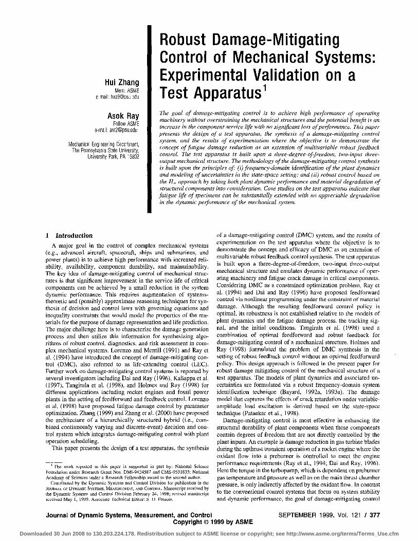
In order to satisfy the above requirements, the test apparatus is designed and fabricated as a three-degree-of-freedom (DOF) mass-beam structure excited by two vibrators. A schematic,diagram of the test apparatus and the instrumentation is shown in Fig. 1 and dimensions of the pertinent components are listed in Table 1. The test apparatus is logically partitioned into two subsystems: (i) the plant subsystem consisting of the mechanical structure including the test specimen to undergo fatigue damage; and (ii) the control and instrumentation subsystem consisting of computers, data acquisition and processing, communications hardware and software, and sensors and actuators. The sensors include: 2 load cells for force measurement; 3 Linear Variable Differential Transformer (LVDT) devices for displacement measurement; 3 accelerometers for acceleration measurement; and 2 strain gauges for strain measurement.
The two actuators (i.e., vibrator#l and vibrator#2 in Fig. 1) directly control two out of the three DOFs whereas the remaining DOF is observable via displacement measurements of the three vibrating masses as seen in Fig. 1. The test specimen, subjected to stress oscillations, is representative of a plant component suffering fatigue crack damage. The mechanical structure is excited at the designed resonance frequency (—6.21 Hz) so that the critical component(s) can be excited at different levels of cyclic stress excitation with no significant change in the external power injection into the actuators (i.e., vibrators). The excitation force vector generated from two vibrators serves as the inputs to the multi-degree-of-freedom mechanical structure to satisfy the Requirement #1. The (analytically derived) modal shapes of vibration corresponding to the first four modal frequencies, 6.5205 Hz, 13.670 Hz, 17.646 Hz, and 68.308 Hz, are plotted in Fig. 2. Note that the actual modal frequencies of the test apparatus structure are not exactly equal to the analytically derived values because of modeling uncertainties including parametric inaccuracies. For example, it is shown later in Section 3 that the first modal frequency of
Mode 1, Frequency 6.5205 H z
0.00 0.25 0.50 0.75 2.00
Mode 2, Frequency ; 13.670 H z
0.25 0.50
Mode 3, frequenc y v/.iAb t 2 -T>~,
0.00 0.26 0.75 1.00
ode 4, Free uency: 6E 308 Hz -
Fig. 1 Schematic diagram of the test apparatus
0.00 0.25 0.60 0.75 1.00 1.25 1.50 1.75 2.00 Length of the Test Apparatus Structure (meters)
Fig. 2 Analytically derived first four modal shapes of the test apparatus structure
378 / Vol. 121, SEPTEMBER 1999 Transactions of the ASME
Downloaded 30 Jun 2008 to 130.203.224.178. Redistribution subject to ASME license or copyright; see http://www.asme.org/terms/Terms_Use.cfm

the structure is identified to be —6.21 Hz based on the experimental data.
Two configurations are considered for conducting DMC experiments on the test apparatus where two actuators simultaneously manipulate the vibratory motions of the mechanical structure. The performance variables in the first configuration are the two displacements, yi and yj, of Mass#l and Mass#2, respectively, that are measured by LVDT sensors. The corresponding reference trajectories are two out-of-phase square-wave signals whose frequency is 5 of the first modal frequency of the structure. In the second configuration, the displacement of Mass#l, y,, is the only performance variable and the corresponding reference trajectory is a square-wave signal whose frequency is also 5 of the first modal frequency of the structure. In both configurations, the structure becomes resonant at the first modal frequency that is identically equal to the third harmonic of the reference signal. The objective of the controller is to significantly mitigate the fatigue crack damage at the failure site without significantly compromising the dynamic performance of the structure. This implies that the tracking errors (i.e., deviations of the performance variables from the corresponding reference signals) should be kept as low as possible while the fatigue life of the test specimen is significantly enhanced.
The position of Mass#3, y,, is measured by another LVDT and is not directly controlled by any one of the two vibrators as seen in Fig. 1. The failure site is introduced 25.4 mm (1 inch) from the Mass#3 as a hole in the test specimen (Beam#2) where cyclic stresses cause fatigue crack damage. The purpose of the hole is to ensure that the test specimen undergoes a larger amplitude of cyclic stress than the rest of the test apparatus to satisfy the Requirement #2. Although the hole creates a failure site, it does not significantly alter the macroscopic parameters (e.g., modal frequencies) of the structure. Note that y^ strongly influences the beam curvature at the failure site, which is weakly affected by one of the performance variables, y 2, and is not directly affected by the other performance variable, y 1. This is how Requirement #3 of no strong coupling is realized in the test apparatus.
2.1 Stress Evaluation at the Failure Site. The stress information is needed as a signal to determine the fatigue crack damage. To establish a relationship between the measurable variables and the far-field stress at the failure site, two methods are considered: (i) Direct strain measurements (ii) Finite element modeling and displacement measurements. To directly measure the local strains by the first method, at least one sensor is needed to be installed on each (disposable) specimen, which is both time consuming and expensive. Therefore, we have adopted an alternative way to estimate the far-field stress at the failure site by the second method based on a finite-element model of the test apparatus structure. The estimated far-field stress 0-2(0 at the failure site is generated as an algebraic function of the displacement measurements, yi(t),y2(t), and y^(t), which are obtained as on-line sensor data in the experiments:
o'lit) = ZJ ^kykil) with constant parameters p, = 1.5025;
/ 3 2 = - 9 . 4 0 9 5 ; jSj = 13.1437 in SI units (1)
Equation (1) is dependent on the displacement measurements only and is found to be within 5% accuracy by comparison with strain gauge data.
3 System Identification for Robust Control Syntliesis
The goal of robust control synthesis is to achieve a trade-off between stability and performance of the closed loop system under specified uncertainty conditions of the open-loop plant model that is typically derived based on a priori information (e.g., fundamental laws of physics, plant operating conditions and physical dimensions). Although the plant model parameters can be identified via
either time-domain or frequency-domain techniques, we have chosen frequency-domain approach for identification of modeling uncertainties as needed for H„-hased synthesis of a robust control system for the resonance-dependent test apparatus under consideration. In our experience, commercially available codes (e.g., the Matlab System Identification Toolbox™ and Frequency Domain Identification Toolbox''''^) are inadequate for plant and uncertainty model identification as needed for robust multivariable controller design. Specifically, these codes provide either system parameter estimation error or curve fitting error and are incapable of handling Multiple-Input Multi-Output (MIMO) problems in frequency domain identification. Bayard (1992a, 1992b, 1993a) has developed a frequency-domain method of system identification based on Schroeder-phased sinusoidal input excitation for the explicit purpose of designing robust multivariable H„ controllers. The salient features of this method are:
• The plant uncertainty set is directly identified from experimental data.
• Complete statistical characterization, namely, chi-square distribution, of the plant uncertainties is identified.
• The Schroeder-phased sinusoidal input excitation is used to ensure that: (i) the distribution of the identification error is plant-independent; (ii) the discrete Fourier Transform (DFT) estimator is unbiased for any data length (and hence does not require a special frequency windowing function) and the unbiased estimate is free from windowing distortions (i.e., avoids the usual "leakage effects" of DFT); and (iii) the errors at each frequency grid point are statistically independent.
The identification method, used in this paper, is built upon the State-Space from Frequency Data (SSFD) algorithm of Bayard (1992a, 1992b, 1993a, 1993b). The identification procedure starts from construction of an excitation signal which is a Schroeder-phased multi-sinusoidal input (Bayard, 1992b). This signal is applied to each input (i.e., actuator) of the plant, one at a time, until the respective output reaches the steady state. The steady-state Input/Output data are acquired and then averaged using the scheme of spectral estimation processing (Bayard, 1992b). Subsequently, a complete Multiple Input Multiple Output (MIMO) plant estimate is constructed from the series of Single Input Multiple Output (SIMO) experiments. The plant spectral estimate is curve-fitted by minimizing a weighted Euclidean norm error criterion using the algorithm of Bayard (1992a) to obtain a multivariable transfer matrix in the polynomial form.
The additive uncertainty region is then characterized in non-parametric form within a prescribed statistical confidence via the statistical plant set estimation method of Bayard (1992b). The non-parametric plant set estimation is then upper-bounded in a parametric form that serves as the uncertainty weighting function in the controller design. At this point, both a nominal state-space plant model and an additive (frequency-dependent) uncertainty weighting function become available for robust control synthesis.
4 Synthesis of Robust Damage-Mitigating Control Laws
The synthesis of a damage-mitigating control (DMC) system can be viewed as a multi-objective optimization problem. The first step is to generate an open loop feed-forward control policy, if applicable, with additional constraints to capture the dynamics of material damage as extensively discussed by Ray et al. (1994), Dai and Ray (1996), and Tangirala et al. (1998). The resulting control policy is optimal but not necessarily robust relative to the accuracy of the plant model and shape of the reference input. Considering nonlinearifies of the fatigue damage model (Patankar et al., 1998), even suboptimality of the control system cannot be guaranteed to accommodate modeling uncertainties including parametric changes. To cast this problem into a feedback control framework. Holmes and Ray (1998) include the damage-mitigating feature in
Journal of Dynamic Systems, Measurement, and Control SEPTEMBER 1999, Vol. 121 / 379
Downloaded 30 Jun 2008 to 130.203.224.178. Redistribution subject to ASME license or copyright; see http://www.asme.org/terms/Terms_Use.cfm
J^^W __5^""(k)
» H I F — • Structural
Model
ys»(k)
Damage Damage Model
5D{k) Damage Increment
[s] Sample [ ^ Hold
Fig. 3 Schematic diagram for damage-mitigating control systems
the synthesis of i/„-based linear feedback control. A more profound treatment (which is a subject of current research) is to augment the plant with a state-space model of fatigue crack growth and then design a nonlinear robust feedback controller based on the augmented plant model (Lorenzo et al., 1998).
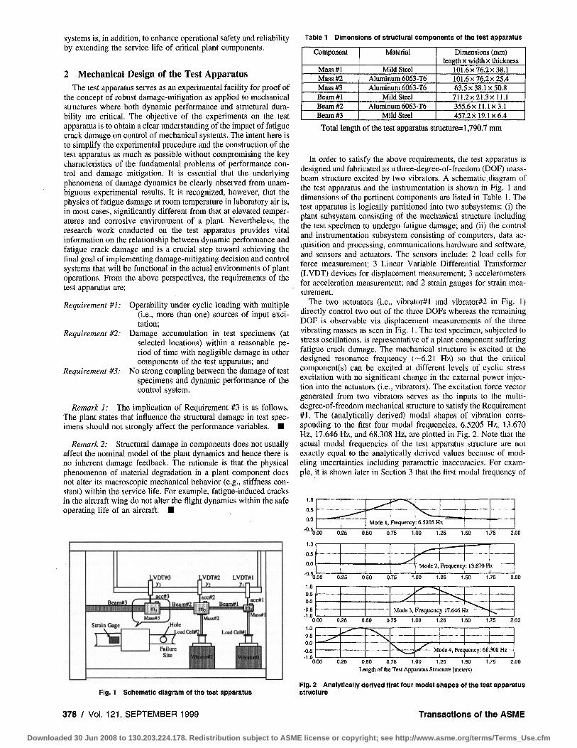
4.1 Damage-Mitigating Control Arcliitecture. The schematic diagram in Fig. 3 shows the general architecture of the damage mitigating control (DMC) system where the plant is the test apparatus described in Fig. 1 whose (continuous-time) nominal model is presented later in Section 5. The plant has two types of sensor outputs y''"'(k) and y'^^ik). The vector signal y''""{k) contains the plant outputs that are necessary for calculation of stress (and damage) at the failure site of the test specimen. The vector signal y"''^ik) consists of the plant outputs that are required to follow the reference trajectory vector. The Structural Model in Fig. 3 uses y''""(k) as an input to generate damage-causing variables y^'^k) such as stresses that, in turn, excites the damage model whose output is both fatigue crack damage accumulation D(k) and increment 8D{k). The purpose of the Damage Model is to capture the characteristics of material degradation under cyclic stresses. The fatigue crack damage model is highly nonlinear and is normalized to have an output D(k) in the range [0, 1] where a value of 0 can be interpreted as zero damage and a value of 1 implies that the service life of the component has ended. The damage model is briefly described in Appendix A and the details are reported by Patankar et al. (1998).
The purpose of the Linear Tracking Controller in Fig. 3 is to keep the error signal e"^(k) as close to zero as possible, i.e., to track the reference signal y'""(k), and to provide robust stability in the inner control loop. The feedforward control input, u^-^(k), obtained from the Feedforward Signal Generator, is calculated a priori. This step is similar to the work reported by Holmes and Ray (1998) but different from the work reported by Ray et al. (1994) and Dai and Ray (1996) where the feedforward sequence was generated by constrained optimization.
4.2 Damage-Mitigating Controller Design. Now we propose H„-based robust control synthesis that utilizes the identified models of plant dynamics and additive uncertainty. The //„ synthesis can be viewed as an unconstrained optimization procedure that trades off dynamic performance with stability robustness (Sa'nchez-Peiia and Sznaier, 1998). The very art of a successful controller design is in the selection of the performance weighing functions. Focusing on the test apparatus control problem, we identify the frequency-dependent weighting functions for modeling uncertainty and performance specifications (Tangirala et al., 1998; Holmes and Ray, 1998) to achieve a trade-off between robust performance and structural durability.
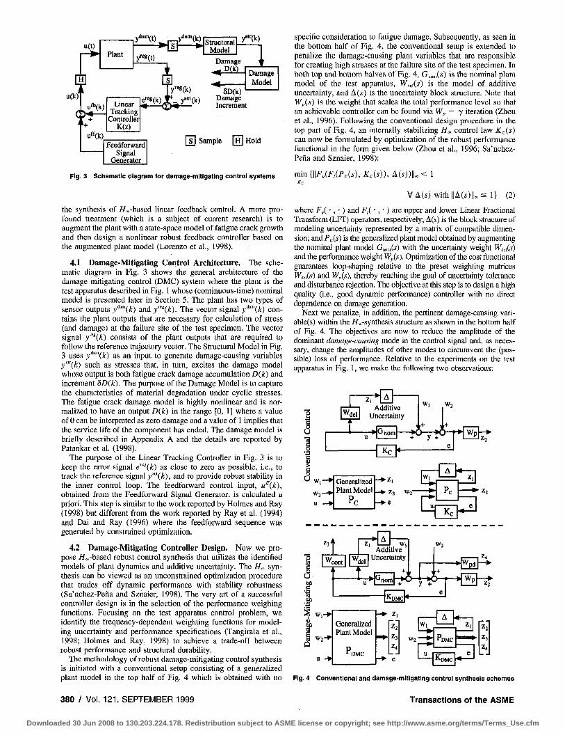
The methodology of robust damage-mitigating control synthesis is initiated with a conventional setup consisting of a generalized plant model in the top half of Fig. 4 which is obtained with no
specific consideration to fatigue damage. Subsequently, as seen in the bottom half of Fig. 4, the conventional setup is extended to penalize the damage-causing plant variables that are responsible for creating high stresses at the failure site of the test specimen. In both top and bottom halves of Fig. 4, G„o,„(i) is the nominal plant model of the test apparatus, WM(S) is the model of additive uncertainty, and A(s) is the uncertainty block structure. Note that Wi,(s) is the weight that scales the total performance level so that an achievable controller can be found via W,, — y iteration (Zhou et al., 1996). Following the conventional design procedure in the top part of Fig. 4, an internally stabilizing //„ control law Kds) can now be formulated by optimization of the robust performance functional in the form given below (Zhou et al, 1996; Sa'nchez-Pefia and Sznaier, 1998):
min {\\F,iF,{Pcis), Kds)), A(i))|U < 1 Kc
VA(.s) with||A(.s)|U< 1} (2)
where F„( •, •) and F,(-, •) ar& upper and lower Linear Fractional Transform (LFT) operators, respectively; A(.y) is the block structure of modeling uncertainty represented by a matrix of compatible dimension; and Pc{s) is the generaUzed plant model obtained by augmenting the nominal plant model G„„„(s) with the uncertainty weight W^ds) and the performance weight Wp{s). Optimization of the cost functional guarantees loop-shaping relative to the preset weighting matrices WdeiW and Wp(s), thereby reaching the goal of uncertainty tolerance and disturbance rejection. The objective at this step is to design a high quality (i.e., good dynamic performance) controller with no direct dependence on damage generation.
Next we penalize, in addition, the pertinent damage-causing vari-able(s) within the //„-synthesis structure as shown in the bottom half of Fig. 4. The objectives are now to reduce the amplitude of die dominant damage-causing mode in the control signal and, as necessary, change the amplitudes of other modes to circumvent the (possible) loss of performance. Relative to the experiments on the test apparatus in Fig. 1, we make the following two observations:
i
1 U
Wdel , k
Z i * ' A •
Auuiuve Uncertainty
'-'noni
Kc
K
Wl W,
)' *l ,+
.. J V T*-"
( e
Wp
u -
Generalized Plant Model
Pc • Z2 W2'
• e
w, ^ - ^
^
• " - ^
Pc
Kc
^3*
I CO
f ^ W i -
W., W, 'del
J Wj Additive
Uncertainty
*-T* i-*4
W2
•jWgd
> 0 f > Wp y +
W 2 - ^
Generalized Plant Model
p
Z|
Z-.
Z3
Z4
e
W2
W| - A
PDMC
KDMC
Z|
e
Fig. 4 Conventional and damage-mitigating controi synthesis schemes
380 / Vol. 121, SEPTEMBER 1999 Transactions of the ASME
Downloaded 30 Jun 2008 to 130.203.224.178. Redistribution subject to ASME license or copyright; see http://www.asme.org/terms/Terms_Use.cfm

• The first mode is responsible for resonant vibrations and hence dominates the damage process because the failure site is subjected to higher stress amplitudes with larger vibration of the free Mass#3. Penalizing this resonant mode does not strongly affect the system performance (i.e., tracking ability of Mass#l and Mass#2).
• The displacement of Mass#3 is not a performance variable and is not directly controlled by any one of the two actuators but its motion significantly affects the stress amplitude at the failure site.
The robust controller is now designed based on the above two physical phenomena by including three additional variables that are the displacement, y-^, of Mass#3 and the two control inputs (i.e., signals exciting the actuators), w, and «,. The estimated far-field stress, a-2, at the failure site (obtained as a linear combination of the displacements, j i , y2> and y^, via Eq. (2)) and both control inputs, M, and M2, are penalized by frequency-dependent weights, W,,/(.s) and Wc„„i(«), respectively. Following the damage-mitigafing procedure in the bottom part of Fig. 4, an internally stabilizing H„ control law K^yicis) can now be formulated and solved to optimize the robust performance in the form given below:
min {||F„(F,(/̂ DMc(̂ )> /fDMc(̂ O), A(^))!U < 1
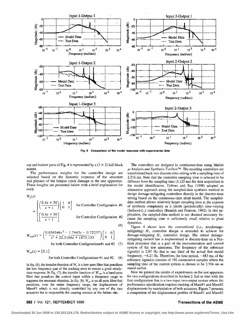
is then balanced and reduced to generate the discrete-time state-space setting (Zhou et al., 1996). The plant model for robust controller design has eight states, two control (i.e., actuator command) inputs, three outputs (i.e., displacements of the three masses). The first two outputs are treated as performance variables and all three outputs are used to generate the far-field stress for synthesis of the damage mitigating control law. Figure 5 compares the Bode magnitude plots of the six transfer functions of the identified model with those of the respective experimental data. The resonant frequency of the vibrating structure in the test apparatus is —6.21 Hz. The identification procedure is conducted with a sampling time of 3.125 ms for data acquisition. The frequency of excitation signal ranges from 0 to 160 Hz with 4096 data points. Therefore, the resulting frequency resolution is 0.078125 Hz. The discrete-time plant model is converted to the continuous-time domain with the sampling time T, = 3.125 ms. The resulting continuous-time state-space model is again balanced to generate the nominal plant model G„„,„(i-) for controller design described in Section 4. The models of plant, uncertainty and performance weights are presented below:
\x{t) = kx{i) + Bu{t) y^^) "^ \y{i) =• Cx{f) \ Du{t) (4)
VA(i') with I! A (.s) 1} (3) where
A =
12.334/ 1 -0.2442 2.0873 0.2892 -12.6160 -45.1486
-2.5686 43.9109 -42.4215 44.2971 5.776! 1.470/ 0.528' 10.357?
C =
-3.3459 10.5402 32.7387 -61.3690
1 -11.4701 30.0693 ' 1.5159 -5.4316 i -0.5226 6.2207
-45.4482 2.9354 7.4735
-91.1235 -0.0054 -6.8968 -5.8283
-74.8315
-7.2123 -29.4505 -27.2888 -25,6785 -64.5499 -96.5308 -5.8722 -18.6879
'0.0001 -0.0033 -0.0232 -0.0050 0.0205 0.0126 -0.0588 -0.0448 0.0173 -0.0367 0.0634 0.0120 0.0045 0.0667 0.0195
B =
3.5093 -17.2325 18.6961 -6.2382 16.6041 -7.8283 0.8360
. -1.9179
-1.9009 9.6131 13.5764 -7.5726 -45.9878 -0.4557 0.8842
-4.6380
0.0069 0.0154
-0.0007
18.9213' 3.2579
-1.8578 -25.0847 -6.6138 0.8071
-0.5235 -8.3043.
0.0297 -0.6609 2.2892 14.3289 -5.3407 4.2777 11.7917 -66.2060 -
0.0057 -0.0025 -0.0037
; and D
15.0672 0.0835
-7.3930 85.2843 28.2589 9.1054
-96.4984 -46.2613.
0.0021" -0.0049 -0.0188_
= U \J
0 0 0 0
where F,X • , • ) , F,{ • , • ) , and A(i) are the same as defined in Eq. (2); and PDMCM is the generalized plant model obtained by augmenting the nominal plant model G„„,^{s) with the uncertainty weight Wjci('*) and the performance weights W,,{'i), Wi„i(s), and Wcmis) following the bottom part of Fig. 4. Note that the damage-mitigating controller ^DMC(^), generated from Eq. (3), is of higher order than the conventional controller Kds), generated from Eq. (2), because PDMC('S) is of higher order than Pc(s) due to dynamics of the additional performance weights.
5 Experimental Results and Discussion The transfer matrix of (the open loop) model of the structure has
been identified in the discrete-time setting in Section 3. The model
The plant modeling uncertainty weight W^^ is obtained by a least-square fit of the non-parametric uncertainty model generated by system identification of experimental data described in Section 3:
0.017757.5^ + 5.4138i^ + 73.0835^ + 1480.1260\
s^ + 12.5303^' + 1635.4813J + 7606.1516 /
X 1 0 0 1 (5)
Figure 6 shows a comparison of the transfer function of W^a with that of the non-parametric uncertainty model, identified from experimental data. The structure A (.5) of modeling uncertainty in the
Journal of Dynamic Systems, Measurement, and Control SEPTEMBER 1999, Vol. 121 / 381
Downloaded 30 Jun 2008 to 130.203.224.178. Redistribution subject to ASME license or copyright; see http://www.asme.org/terms/Terms_Use.cfm
i)-60
10
JO
3 u T) a
t •2
s
-20
-40
-60
-80
-20
S - 4 0 •a
'JT-eo 1 - 8 0 & | -100
-120 10
Input 1-Output 1
— Model Data Test Data
1
^ i ^ x,
\ \
-
10 10̂ 10' 10' Frequency (rad/sec)
Input 1-Output 2
10 10" 10' 10 Frequency (rad/sec)
Input I-Output 3
10"̂ 10 ' 10' Frequency (rad/sec)
W- 10"
1 Vlodel Data rest Data
10- 10'
Model Da Test Data
la
nJL
10- 10"
Input 2-Output 1
-2 -1 10 ^ 10 '
-20
§, -40
1 "̂ 1-80
-100
IQO 10' 10' Frequency (rad/sec)
Input 2-Output 2
10- 10'
. , _ _ .
- Model Data j f - Test Data '
...
7
10 10 10^ 10' 10 10- 10" Frequency (rad/sec)
Input 2-Output 3
u -50
•|-ioo
-150 — Test Data
10 10^ 101 10 ^ 10 -
Frequency (rad/sec) 10"
Fig. 5 Comparison of the model response with experimental data
top and bottom parts of Fig. 4 is represented by a (3 X 2) full-block matrix.
The performance weights for the controller design are selected based on the dynamic response of the structure and physics of the fatigue crack damage in the test apparatus. These weights are presented below with a brief explanation for each:
WJs)
= <,
OAs + 50
.5-1- 1
O.4.? + 50 s + 1
1 0 0 1
for Controller Configuration #1
for Controller Configuration #2
(6)
_ '0.036546.$^ + 1.7443.S + 0.72237\
s' + 22.5166.?-I- 1873.133 1 0 0 1
for both Controller Configurations*! and #2 (7)
W,,(^) = [0.1]
for both Controller Configurations #1 and #2. (8)
In Ekj. (6), the transfer function of Wp is a low-pass filter that penalizes the low frequency part of the tracking error to ensure a good steady-state response. In Eq. (7), the transfer function of W^OM is a band-pass filter that penalizes the control input within a frequency range to suppress the resonant vibration. In Eq. (8), Wpd is an all-pass filter that penalizes, over the entire frequency range, the displacement of Mass#3 which is not directly controlled by any one of the two actuators but is responsible for causing stresses at the failure site.
The controllers are designed in continuous-time using Matlab /^.-Analysis and Synthesis Toolbox''̂ '̂ . The resulting controllers are transformed back into discrete-time setting with a sampling time of 2.516 ms. Note that the controller sampling time is selected to be different from the sampling time (3.125 ms) for data acquisition in the model identification. Holmes and Ray (1998) adopted an alternative approach using the sampled-data synthesis method to design damage-mitigating controllers directly in the discrete-time setting based on the continuous-time plant model. The sampled-data method allows relatively larger sampling time at the expense of synthesis complexity as it yields (periodically) time-varying (induced-L2) controllers (Bamieh and Pearson, 1992). In this application, the sampled-data method is not deemed necessary because the sampling time is sufficiently small relative to plant dynamics.
Figure 4 shows how the conventional (i.e., nondamage-mitigating) H„ controller design is extended to achieve the damage-mitigating //„ controller design. The robust damage-mitigating control law is implemented in discrete-time on a Pentium processor that is a part of the instrumentation and control system of the test apparatus. The frequency of the reference signal(s) is 2.07 Hz that is one third of the actual first modal frequency, —6.21 Hz. Therefore, the time period, —483 ms, of the reference signal(s) consists of 192 consecutive samples where the sampling time of the control system is chosen to be 2.516 ms as stated earlier.
Now we present the results of experiments on the test apparatus for two configurations described in Section 2. Let us start with the first configuration that is a two-input two-output system where the performance specification requires tracking of Mass#l and Mass#2 displacements by manipulation of both actuators. Figure 7 presents a comparison of the displacement profiles of Mass#l and Mass#2
382 / Vol. 121, SEPTEMBER 1999 Transactions of the ASME
Downloaded 30 Jun 2008 to 130.203.224.178. Redistribution subject to ASME license or copyright; see http://www.asme.org/terms/Terms_Use.cfm
10 t '"I
« lo-i a I
10 -3
W,
Non-parametric Uncertainty Model > I 11 m l
,1 10 10 10' 1 0 '
Frequency (rad/sec)
Fig. 6 Frequency response of plant modeling uncertainties
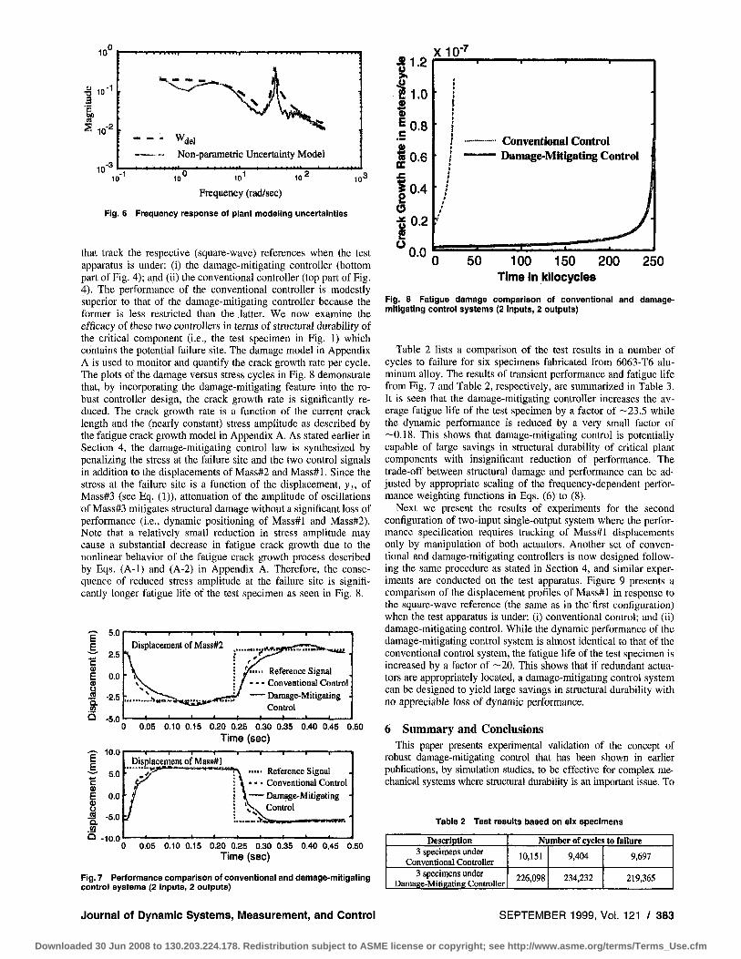
that track the respective (square-wave) references when the test apparatus is under: (i) the damage-mitigating controller (bottom part of Fig. 4); and (ii) the conventional controller (top part of Fig. 4). The performance of the conventional controller is modestly superior to that of the damage-mitigating controller because the former is less restricted than the latter. We now examine the efficacy of these two controllers in terms of structural durability of the critical component (i.e., the test specimen in Fig. 1) which contains the potential failure site. The damage model in Appendix A is used to monitor and quantify the crack growth rate per cycle. The plots of the damage versus stress cycles in Fig. 8 demonstrate that, by incorporating the damage-mitigating feature into the robust controller design, the crack growth rate is significantly reduced. The crack growth rate is a function of the current crack length and the (nearly constant) stress amplitude as described by the fatigue crack growth model in Appendix A. As stated earlier in Section 4, the damage-mitigating control law is synthesized by penaUzing the stress at the failure site and the two control signals in addition to the displacements of Mass#2 and Mass#l. Since the stress at the failure site is a function of the displacement, y,, oi Mass#3 (see Eq. (1)), attenuation of the amplitude of oscillations of Mass#3 mitigates structural damage without a significant loss of performance (i.e., dynamic positioning of Mass#l and Mass#2). Note that a relatively small reduction in stress amplitude may cause a substantial decrease in fatigue crack growth due to the nonlinear behavior of the fatigue crack growth process described by Eqs. (A-1) and (A-2) in Appendix A. Therefore, the consequence of reduced stress ampUtude at the failure site is significantly longer fatigue life of the test specimen as seen in Fig. 8.
^ 2.5
E 0.0
•Q. '^'S
Q -5.0
— T 1 I I Displacement of Mass#2
Reference Signal - - - Conventional Control
Damage-Mitigating Control
—I I I I 0.05 0.10 0.15 0.20 0.25 0.30 0.35 0.40 0.45 0.50
Time (sec) I I I I
Displacement of Mass#l Reference Signal Conventional Control
- Damage-Mitigating • Control
0.05 0.10 0.15 0,20 0.25 0.30 0.35 0.40 0,45 0.50 Time (sec)
Fig. 7 Performance comparison of conventional and damage-mitlgating control systems (2 inputs, 2 outputs)
^1.? u > 42 21.0 0) % ^0.8
0 | 0 . 6 £
| 0 . 4 ^ O •gO.2
xio-^ •
!
• /
V
•MfMIMMi
•
•
Conventional Control — Damage -Mitigating Control
, 1 /
J •
50 100 150 200 Time in Icliocycies
250
Fig. 8 Fatigue damage comparison of conventional and damage-mitigating control systems (2 inputs, 2 outputs)
Table 2 lists a comparison of the test results in a number of cycles to failure for six specimens fabricated from 6063-T6 aluminum alloy. The results of transient performance and fatigue life from Fig. 7 and Table 2, respectively, are summarized in Table 3. It is seen that the damage-mitigating controller increases the average fatigue life of the test specimen by a factor of —23.5 while the dynamic performance is reduced by a very small factor of —0.18. This shows that damage-mitigating control is potentially capable of large savings in structural durability of critical plant components with insignificant reduction of performance. The trade-off between structural damage and performance can be adjusted by appropriate scaling of the frequency-dependent performance weighting functions in Eqs. (6) to (8).
Next we present the results of experiments for the second configuration of two-input single-output system where the performance specification requires tracking of Mass#l displacements only by manipulation of both actuators. Another set of conventional and damage-mitigating controllers is now designed following the same procedure as stated in Section 4, and similar experiments are conducted on the test apparatus. Figure 9 presents a comparison of the displacement profiles of Mass#l in response to the square-wave reference (the same as in the first configuration) when the test apparatus is under: (i) conventional control; and (ii) damage-mitigating control. While the dynamic performance of the damage-mitigating control system is almost identical to that of the conventional control system, the fatigue life of the test specimen is increased by a factor of —20. This shows that if redundant actuators are appropriately located, a damage-mitigating control system can be designed to yield large savings in structural durability with no appreciable loss of dynamic performance.
6 Summary and Conclusions This paper presents experimental validation of the concept of
robust damage-mitigating control that has been shown in earlier publications, by simulation studies, to be effective for complex mechanical systems where structural durability is an important issue. To
Table 2 Test results based on six specimens
Description 3 specimens under
Conventional Controller 3 specimens under
Damage-Mitigating Controller
Number of cycles to failure
10,151
226,098
9,404
234,232
9,697
219,365
Journal of Dynamic Systems, Measurement, and Control SEPTEMBER 1999, Vol. 121 / 383
Downloaded 30 Jun 2008 to 130.203.224.178. Redistribution subject to ASME license or copyright; see http://www.asme.org/terms/Terms_Use.cfm
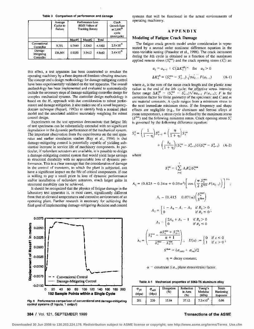
Table 3 Comparison of performance and damage
Conventional Controller Damage-
Mitigating Controller
Average Cycles to Failure
9,751
226,565
Performance Loss (RMS Values of Tracking Errors)
Mass#l
0.7640
0.9250
Mass#2
3.3362
3.9412
Total
4.1002
4.8662
Crack Growth Rate
at 2,000"' cycle
(mm/cycle)
2.5X10''
2.4X10'*
this effect, a test apparatus has been constructed to emulate the operating machinery by a three degree-of-freedom vibrating structure, liie concept and a design methodology for damage-mitigating control have been experimentally validated on the test apparatus. The overall methodology has been implemented and evaluated to systematically include the necessary steps of damage-mitigating controller design for complex mechanical systems. The controller design methodology is based on the //„ approach vi'ith due consideration to robust performance and damage mitigation. It also makes use of a novel frequency-domain technique (Bayard, 1992a) to identify both a nominal plant model and the associated additive uncertainty weighting for robust control design.
Experiments on the test apparatus demonstrate that fatigue life of test specimens can be substantially extended with no significant degradation in the dynamic performance of the mechanical system. The important observation from the experiments on the test apparatus and earlier simulation studies (Ray et al., 1994) is that damage-mitigating control is potentially capable of yielding substantial increase in service life of machinery components. In particular, if redundant actuators are available, it is possible to design a damage-mitigating control system that would yield large savings in structural durability with no appreciable loss of dynamic performance. This is a clear message that the consideration of damage in the control of transients, to which the plant is subjected, can have a significant impact on the life of critical components. If one is willing to pay a small price in loss of dynamic performance and/or installation of redundant actuators, much larger gains in structural durability can be achieved.
It should be recognized that the physics of fatigue damage in the laboratory test apparatus is, in most cases, significantly different from that at elevated temperatures and corrosive environment of an operating plant. Further research is necessary for achieving the final goal of implementing damage-mitigating decision and control
0.0075
I -0.0075
-0.0100
Conventional Control Damage-Mitigating Control
0 20 40 60 80 100 120 140 160 180 200 192 Sample Points within a Single Cycle
Fig. 9 Performance comparison of conventional and damage-mitigating control systems (2 Inputs, 1 output)
systems that will be functional in the actual environments of operating machinery.
A P P E N D I X
Modeling of Fatigue Crack Damage The fatigue crack growth model under consideration is repre
sented by a second order nonlinear difference equation in the state-variable setting (Patankar et al, 1998). The crack increment during the ^th cycle is obtained as a function of the maximum applied remote stress (S""^) and the crack opening stress (S°) as:
C{AKf')"' for ao>0
AKf = {SI 2-l) V"^"*-! ^(«t-l) (A-1)
where Oi is the sum of the mean crack length and the plastic zone radius at the end of the /tth cycle; the effective stress intensity factor range AKf = {Sr - S°->)VTTa,.i F{at-i); F is the correction factor for finite geometry of the specimen; and C and m are material constants. A cycle ranges from a minimum stress to the next immediate minimum stress. If the frequency and shape effects are negligible (e.g., for aluminum and ferrous alloys at room temperature), a stress cycle is defined by the maximum stress (S'"'"') and the following minimum stress. Crack opening stress 5° is governed by the following difference equation:
1
1 + T) T1
1 + T)
1 + T) {SI <)U{Sl ,) (A-2)
where
sr = {J, A,Ri)sr
Ao = (0.825 - 0.34a + 0.05a^)
A, = ( 0 . 4 1 5 - 0 . 0 7 1 a ; , ^„„,
2 5"
omax
Ha.-t)
A , = 1 - A n - A , - A , \fRi:>0 ^k
A 3 - 1 0
0 if Ri, SO
2Ao + A, - 1 ifRi,>0 ifR.^0
omax Q:5'r + sr, \
h = a + 1
7 ; u{x) : = 0 if ;c < 0 1 i f x > 0 '
5"°"'=(try„„+o-,J/2
T) = decay constant;
a = constraint (i.e., plane stress/strain) factor.
Table A-1 Mechanical properties of 6063-T6 aluminum alloy
(Mpa)
201
(Mpa)
230
Elongation (%)
15.84
Reduction in Area
(%) 57.12
Young's Modulus
(MPa)
7.2x10''
Strain Hardening Exponent
0.06
384 / Vol. 121, SEPTEMBER 1999 Transactions of the ASIVIE
Downloaded 30 Jun 2008 to 130.203.224.178. Redistribution subject to ASME license or copyright; see http://www.asme.org/terms/Terms_Use.cfm

The material of the specimen (at the failure site in Beam#2 of the test apparatus) is 6063-T6 aluminum alloy. The geometry factor is assumed to be the same as that for center-cracked specimens, i.e., F = Vsec (7ra/2w). The material parameters of 6063-T6 are listed in Table A-1. The model parameters used in Eqs. (A-1) and (A-2) are; C, = 0.62 X 10^"; C, = 3.8; a = 1.6; T) = 2 X 10"'; w = 6.251 X 10^' in SI units.
Acknowledgment The authors acknowledge benefits of technical discussions with
Professor Marc Carpino of Pennsylvania State University.
References Bayard, D. S., 1992a, "Multivariable Frequency Domain Identification Via 2-Norni
Minimization," Proceedings of the American Control Conference, Vol. 2, 1992, pp. 1253-1257.
Bayard, D. S., 1992b, "Statistical Plant Set Estimation Using Schroeder-Phased Multisinusoidal Input Design," Proceedings of the American Control Conference, Vol. 4, 1992, pp. 2988-2995.
Bayard, D. S., 1993a, "Frequency Domain Approach To Identification, Uncertainty Characterization And Robust Control Design," Proceedings of the IEEE Conference on Decision and Control, Vol. 3, 1993, pp. 2266-2271.
Bayard, D. S., 1993b, "Multivariable State-Space Identification in the Delta and Shift Operators: Algorithms And Experimental Results," Proceedings of the American Control Conference 1993, Vol. 3, pp. 3038-3042.
Bamieh, B. A., and Pearson, J. B., 1992, "A General Framework for Linear Periodic Systems with Applications to H^, Sampled-Data Control," IEEE Transactions on Automatic Control, Vol. 37, No. 4, April, pp. 418-435.
Dai, X., and Ray, A., 1996, "Damage-Mitigating Control of a Reusable Rocket Engine: Parts I and II," ASME JOURNAL OF DYNAMIC SYSTEMS, MEASUREMENT, AND
CONTROL, Vol. 118, No. 33, September, pp. 401-415.
Holmes, M., and Ray, A., 1998, "Fuzzy Damage Mitigating Control of Mechanical Structures," ASME JOURNAL OH DYNAMIC SY,STEMS, MEASUREMENT, AND CONTROL, Vol.
120, No. 2, pp. 249-256. Kallappa, P. T., Holmes, M., and Ray, A., 1997, "Life Extending Control of Fossil
Power Plants for Structural Durability and High Performance," Automatica, Vol. 33, No. 6, pp. 1101-1118.
Kumar, R., 1990, "Experimental Observation of Crack Propagation in 6063-T6 Al-AUoy Under Constant Amplitude Loading," International Journal of Pressure Vessel & Piping, Vol. 42, pp. 303-315.
Lorenzo, C. F., and Merrill, W. C, 1991, "Life Extending Control: A Concept Paper," American Control Conference, Boston, MA, June, pp. 1080-1095.
Lorenzo, C. F., Holmes, M., and Ray, A., 1998, Design of Life Extending Control Using Nonlinear Parameter Optimization, Lewis Research Center Technical Report No. NASA TP 3700.
Patankar, R., Ray, A., and Lakhtakia, A,, 1998, "A State-Space Model of Fatigue Crack Dynamics," International Journal of Fracture, Vol. 90, No. 3, pp. 235-249.
Ray, A., Wu, M-K., Carpino, M., and Lorenzo, C. P., 1994, "Damage-Mitigating Control of Mechanical Systems: Parts 1 and II," ASME JOURNAL OR DYNAMIC SYSTEMS, MEASUREMENT, AND CONTROL, Vol. 116, No. 3, Sept., pp. 437-455.
Sa'nchez-Peiia, R. S., and Sznaier, M., Robust Systems Theory and Applicatlom, John Wiley, New York.
Tangirala, S., Holmes, M., Ray, A., and Carpino, M., 1998, "Life-Extending Control of Mechanical Structures: A Feedforward/Feedback Approach," Automatica, Vol. 34, No. 1, January, pp. 3-14.
Zhang, H., 1999, "Intelligent Decision and Control of Mechanical Systems for Life Extension and High Performance," Doctoral Dissertation in Mechanical Engineering, The Pennsylvania State University, May.
Zhang, H., Ray, A., and Phoha, S., 2000, "Hybrid Life Extending Control of Mechanical Systems: Experimental Validation of the Concept," to appear in Automatica, Vol. 36, No. 1, Jan.
Zhou, K., Doyle, J. C , and Glover, K., 1996, Robust and Optimal Control, New Jersey, Prentice-Hall.
Journal of Dynamic Systems, Measurement, and Control SEPTEMBER 1999, Vol. 121 / 385
Downloaded 30 Jun 2008 to 130.203.224.178. Redistribution subject to ASME license or copyright; see http://www.asme.org/terms/Terms_Use.cfm