Embed Size (px)
Citation preview

This is a repository copy of Robots in machining.
White Rose Research Online URL for this paper:https://eprints.whiterose.ac.uk/147491/
Version: Accepted Version
Article:
Verl, A., Valente, A., Melkote, S. et al. (3 more authors) (2019) Robots in machining. CIRP Annals, 68 (2). pp. 799-822. ISSN 0007-8506
https://doi.org/10.1016/j.cirp.2019.05.009
Article available under the terms of the CC-BY-NC-ND licence (https://creativecommons.org/licenses/by-nc-nd/4.0/).
[email protected]://eprints.whiterose.ac.uk/
Reuse
This article is distributed under the terms of the Creative Commons Attribution-NonCommercial-NoDerivs (CC BY-NC-ND) licence. This licence only allows you to download this work and share it with others as long as you credit the authors, but you can’t change the article in any way or use it commercially. More information and the full terms of the licence here: https://creativecommons.org/licenses/
Takedown
If you consider content in White Rose Research Online to be in breach of UK law, please notify us by emailing [email protected] including the URL of the record and the reason for the withdrawal request.
Robots in machining
Alexander Verl (2)a,*, Anna Valente (2)b, Shreyes Melkote (1)c, Christian Brecher (1)d, Erdem Ozturk (2)e,Lutfi Taner Tunc f
a Institute for Control Engineering of Machine Tools and Manufacturing Units (ISW), University of Stuttgart, Germanyb SUPSI —– University of Applied Sciences and Arts of Southern Switzerland, SwitzerlandcGeorge W. Woodruff School of Mechanical Engineering, Georgia Institute of Technology, USAd Laboratory for Machine Tools and Production Engineering (WZL), RWTH Aachen University, GermanyeAdvanced Manufacturing Research Centre (AMRC), The University of Sheffield, UKf Integrated Manufacturing Technologies Research and Application Centre, Faculty of Engineering and Natural Sciences, Sabanci University, Turkey
1. Introduction
Robots are currently used in industrial machining operations
which involve relatively low cutting force requirements such as
trimming, drilling, and polishing on composite parts, as well as
drilling or deburring, grinding, and milling on metal parts. There
are several aspects that stimulate the use of robots in machining.
The first and main one is the cost — robots cost less compared to
machine tools with the same work space.
During the last decade, a new global sales record has been
achieved for industrial robots (IRs) almost every year. In 2016, a
total of 294,000 units were sold, an increase of 16% compared to
the previous year. This number soared to 381,000 units in 2017,
another 30% more than the previous year [1]. More than 3 million
installed robots are forecasted by 2020, doubling their number in
industrial operation since 2014 [2]. According to the International
Federation of Robotics (IFR), in 2016, 1.4% of IRs were intended for
mechanical cutting, grinding, deburring, milling, and polishing
[1]. This number is low compared to non-processing operations
like handling or assembly, which demonstrates the lack of the use
of robots in machining. However, these developments illustrate the
importance of IRs for machining applications.
Within the large set of operating resources, manufacturing
robots are computer numerically controlled (CNC) machines
conceived for industry for specific material subtraction or
deposition functions (e.g., milling, coating, welding or powder
blasting), as well as metrology and inspection functions, while
flexibly implementing various process strategies by exploiting
several end effectors or even hybrid process chains on different
metals and non-metallic materials. A manufacturing robot is
typically a robotic arm manipulator on a fixed base that performs
repetitive tasks within a local work cell [3]. High-speed robots are
hazardous and demand the exclusion of humans from robotic work
places, where the robots are typically placed inside a cage. In
contrast, collaborative robots are considered safe around humans
because they operate at low speed and stop moving if they
encounter an obstruction.
When it comes to defining machining robots, the attempt to
draw a sharp line to differentiate between them and a machine tool
is not straightforward in a general sense and depends on the
specific scientific and technical discipline (e.g., machine tools are
classified as Cartesian robots in the robotics scientific discipline).
The very term “machining” relates to specific technologies
implemented with various tools (DIN 8580) but embeds in its
etymology the fact that such technologies are implemented on
conventional machine tools. Machining robots should be consid-
ered a subset of the manufacturing robot family. They can generally
be defined as robots executing manufacturing processes, according
to DIN 8580.
Like machine tools, machining robots can accomplish multiple
machining tasks by exploiting different configurations, kinematic
structures and performance targets while integrating a tool (end
effector according to the robotics nomenclature) that performs the
machining process when in contact with the material. The end
effectors integrated on a machining robot can present similar
capabilities as tools mounted on machine tools. Their selection
CIRP Annals - Manufacturing Technology xxx (2019) xxx–xxx
A R T I C L E I N F O
Keyword:
Robot
Machining
Process planning
Control
A B S T R A C T
Robotic machining centers offer diverse advantages: large operation reach with large reorientation
capability, and a low cost, to name a few. Many challenges have slowed down the adoption or sometimes
inhibited the use of robots for machining tasks. This paper deals with the current usage and status of
robots in machining, as well as the necessary modelling and identification for enabling optimization,
process planning and process control. Recent research addressing deburring, milling, incremental
forming, polishing or thin wall machining is presented. We discuss various processes in which robots need
to deal with significant process forces while fulfilling their machining task.
© 2019 Published by Elsevier Ltd on behalf of CIRP.
* Corresponding author.
E-mail address: [email protected] (A. Verl).
CIRP 2028 1–24
Please cite this article in press as: A. Verl, et al., Robots in machining, (2019), https://doi.org/10.1016/j.cirp.2019.05.009
Contents lists available at ScienceDirect
CIRP Annals - Manufacturing Technology
journal homepage: http: / /ees.elsevier.com/cirp/default .asp
https://doi.org/10.1016/j.cirp.2019.05.009
0007-8506/© 2019 Published by Elsevier Ltd on behalf of CIRP.
relies upon product and process driven criteria, along with robot
payload and dynamics. By means of the tool, machining robots can
convert a blank into a final product by executing operations
controlled by the robot’s controller unit. Similarly to machine tools
[4], the motion of a machining robot can be controlled by a CNC
unit, as the machining strategy and trajectory are generated by a
CAD/CAM (computer aided design/manufacturing) system. The
productivity and accuracy of the machining operations depend on
the preparation of the numeric control (NC) programs, the robot
path planning, motion strategy, and dynamics optimization,
together with the robot behavior assessment in the working area.
In metal cutting, for example, there is a growing number of
successful installations where robots have been used in a similar
manner to a machine tool or to a person carrying a metal cutting
hand tool [5]. The current paper will outline and investigate the
opportunities and the range of applications where the adoption of
robots for machining constitutes an instrumental leverage.
1.1. Standard definition for robots in machining
The first patent for what we would now consider a robot was
filed in 1954 by George C. Devol and issued in 1961 [6]. Since then,
the conception and exploitation of robots in industry has brought
disruptive innovation while posing complex scientific and techni-
cal challenges to the scientific communities.
Nowadays, the robot is universally defined as a goal-oriented
machine that can sense, plan and act. According to ISO/IEC
2382:2015 (en), a robot is defined as a mechanical device, usually
programmable, designed to perform tasks of manipulation or
locomotion under automatic control. Similarly, ISO 18646-1:2016
(en) considers a robot as a program actuated mechanism with a
degree of autonomy, moving within its environment to perform
intended tasks. An industrial robot is, in turn, described as an
automatically controlled, reprogrammable, multipurpose manip-
ulator, programmable in three or more axes, which can be either
fixed in place or mobile for use in industrial automation
applications [7].
In the following sections, we will introduce the theoretical
foundations of robotics and then cover the programming tool chain
in robotic machining. Then, an overview of several robotic
machining processes is presented. Finally, we look at emerging
fields of research in this area and draw a number of conclusions.
2. Theoretical foundations
This chapter summarizes the theoretical background needed
for robot machining tasks. Using a robot model enables robot
programs to predict behavior and process parameters. In order to
model a robot, the first section of this chapter describes important
mathematical equations and parameter identification methods.
Considerations on mechanical and geometrical properties of
robots, followed by aspects regarding robot stiffness are then
introduced. Furthermore, the static and dynamic behavior of
industrial robots is explained, and various test results are
presented. Path planning, robot control and process control
strategies are also indispensable when preparing robots for new
tasks, and are also discussed in detail in this chapter.
2.1. Robot modelling
There are different approaches to describing a mechanical
system analytically. The method of Lagrangian equations described
in this section is widely used and an easy way to derive equations
of motion for rigid body robots.
Let q 2 Rn be coordinates of the joint angles for an industrial
robot in the n-dimensional vector space. First, the Lagrangian L is
defined as the difference between the total kinetic and the
potential energy of the system (T and V, respectively) [8]:
L q; _q Þ ¼ T q; _q Þ � V qð Þðð ð1Þ
The kinetic and potential energy are described for each link in
the system. The potential energy is defined as the product of the
mass mi of the ith link, the gravitational acceleration g, and the
height of the center of mass (opposite to the direction of gravity)
for the ith link:
V i qð Þ ¼ mighiðqÞ ð2Þ
In comparison to the potential energy, the kinetic energy is,
however, far more complicated to describe and follows as:
T ¼1
2_q T
Xn
i¼1½miJvi qð ÞT Jvi qð Þ þ Jvi
qð ÞTRiðqÞIiRi qð ÞT JviðqÞ� _q ð3Þ
with the rotational transformation Ri and the inertia matrix Ii for
each link i. A central part in describing the kinetic energy is the
manipulator’s Jacobian J which is a 6 � n matrix for a robot with n
links. The Jacobian contains parts for the linear velocity Jv and the
angular velocity Jv, which are described exemplary for rotational
joints in the following equations [9]:
J ¼JvJv
� �
ð4Þ
with:
Jvi ¼ zi�1 � ðO0n � O0
i�1Þ ð5Þ
Jvi¼ z0i�1 ð6Þ
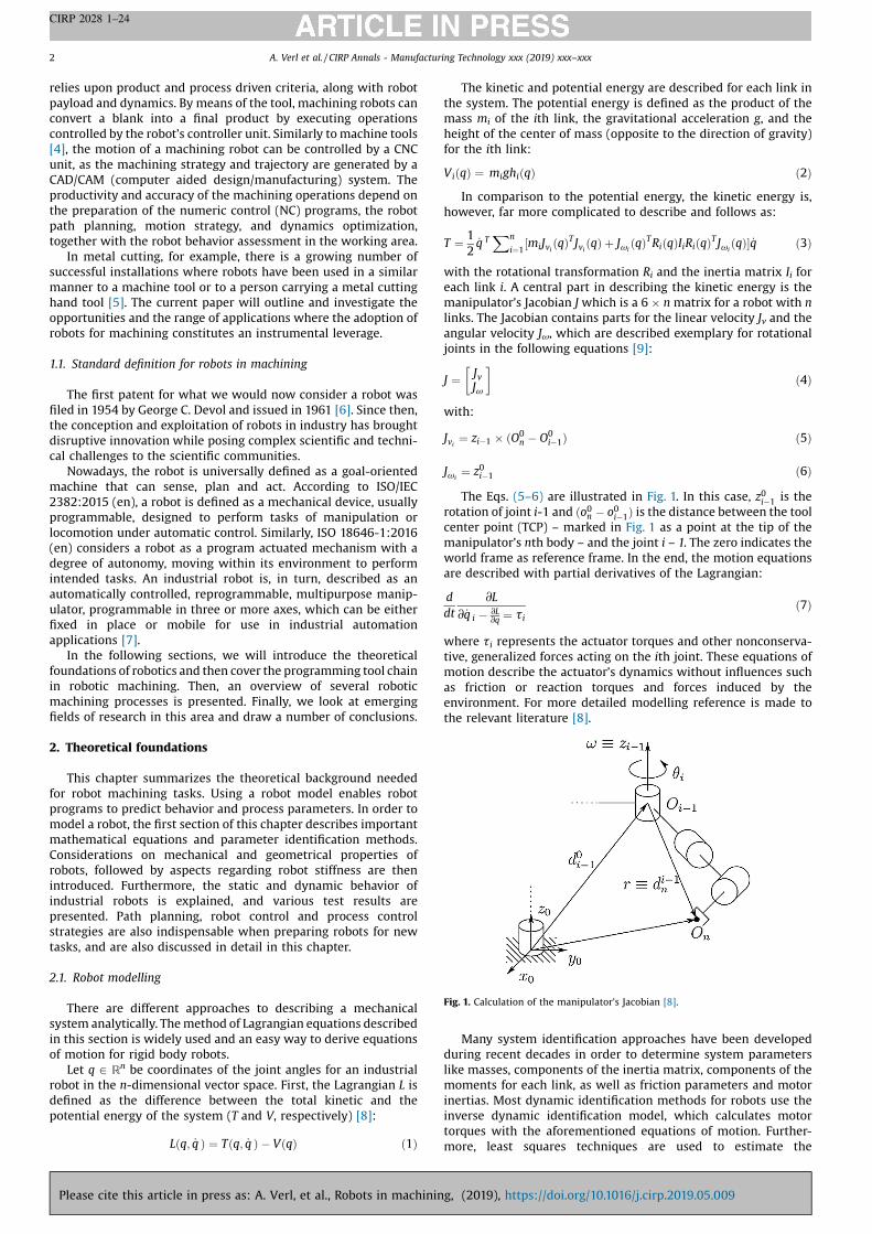
The Eqs. (5–6) are illustrated in Fig. 1. In this case, z0i�1 is the
rotation of joint i-1 and ðo0n � o0i�1Þ is the distance between the tool
center point (TCP) – marked in Fig. 1 as a point at the tip of the
manipulator’s nth body – and the joint i – 1. The zero indicates the
world frame as reference frame. In the end, the motion equations
are described with partial derivatives of the Lagrangian:
d
dt
@L
@ _q i �@L@q
¼ tið7Þ
where ti represents the actuator torques and other nonconserva-
tive, generalized forces acting on the ith joint. These equations of
motion describe the actuator’s dynamics without influences such
as friction or reaction torques and forces induced by the
environment. For more detailed modelling reference is made to
the relevant literature [8].
Many system identification approaches have been developed
during recent decades in order to determine system parameters
like masses, components of the inertia matrix, components of the
moments for each link, as well as friction parameters and motor
inertias. Most dynamic identification methods for robots use the
inverse dynamic identification model, which calculates motor
torques with the aforementioned equations of motion. Further-
more, least squares techniques are used to estimate the
Fig. 1. Calculation of the manipulator’s Jacobian [8].
A. Verl et al. / CIRP Annals - Manufacturing Technology xxx (2019) xxx–xxx2
CIRP 2028 1–24
Please cite this article in press as: A. Verl, et al., Robots in machining, (2019), https://doi.org/10.1016/j.cirp.2019.05.009

parameters. In some cases, a few parameters like masses or
kinematics are already known and therefore do not need to be
identified. As the optimal method depends on the robot and on
these known parameters, reference is made to literature contri-
butions on these topics [10–12]. In addition, there are many ways
to optimize path planning for data acquisition for the identification
process. To increase the least squares methods convergence rate
and lower the susceptibility to noise, an optimal excitement and
implicitly an optimal trajectory is crucial for the process. Hence, a
sequential identification process is often used for estimating the
different parameters with adapted trajectories [13].
2.2. Methods to describe mechanical and geometrical properties
Machining of a workpiece requires a geometrical description of
the machining task and a reference coordinate system in which the
task is described. The task described in these coordinate systems is
then converted to the machine coordinate system by probing. To
execute the machining task, a further transformation to the
machine axis coordinate system (or joint coordinate system) is
required. Machine tool structures with three translational and
optional rotational axes have known and defined transformations.
This is not the case for robotic structures including mostly
rotational axes with optional translation axes.
In robotics literature, the so-called Denavit–Hartenberg (DH)
convention [14] is considered to be the defining set of rules on how
to attach these coordinate systems to the robots’ linkages. The
underlying principle of the DH method is describing the
transformation between two linkages with only four parameters,
representing a combination of two rotations and two translations
[15]. The six parameters generally needed are reduced to four by
applying the convention’s rules — and limitations. Although the
underlying principle remains the same, four different variants of
notations are used in scientific literature [16]. Classification is
based on the index linkages and parameters, which, in conse-
quence, affects the grouping order of the transformation matrices
of the rotations and translations. Instead of attaching only one
coordinate system to each joint, the Sheth–Uicker (SU) convention
[17] attaches two, an input and an output coordinate system. The
relative motion between the two is exactly the joint motion
between the two linkages. The DH parameters can still be used to
describe the relative transformation between the two coordinate
systems attached to one linkage, however, the joint variable term
of the DH parameters for the linkage transformation is only a
constant offset. Although the DH convention operates with half as
many transformations as the SU convention, it is worth noting that
the SU convention allows for a more convenient way to define
coordinate systems of mechanisms that are not strictly serial. It can
also handle complex joint types more conveniently, with more
than one degree of freedom.
2.3. Robot stiffness
Robot stiffness is the key parameter that influences machining
accuracy. Specifically, the limited static and dynamic stiffness of
robot joints and links results in insufficient rigidity of the robot
TCP, which in turn impacts the machining accuracy. As pointed out
by Pan et al. [18], the static Cartesian stiffness of industrial robots is
on the order of 1 N/mm while the corresponding stiffness of a
typical CNC machine tool is up to 50 times higher. Unlike a CNC
machine tool, the Cartesian stiffness of an industrial robot varies
with its joint configuration (or pose) throughout the workspace
[19], which complicates the task of machining process control. The
magnitude and nature of robot deflections are a function of the
magnitude and frequency content of the process forces generated
during machining.
In recent years, the effects of machining process parameters
and robot configuration on the dynamic characteristics of the
robotic machining process and its stability have been investigated.
Bondarenko et al. [20] presented a simulation study of the effect of
robot dynamics on the instantaneous tool-workpiece interaction
in robotic milling with a KUKA KR270 industrial robot. They
modelled and analyzed the effect of robot compliance on the
instantaneous tool tip displacement due to periodically varying
milling forces. However, they did not consider the effect of robot
compliance on the milling forces themselves. Recently, Cen and
Melkote [21] modelled and analyzed the effect of robot compliance
on the instantaneous milling forces. Through simulation and
experiments, they showed that the peak milling force (Fig. 2), and
hence the tool tip deflection, can be significantly under predicted if
this effect is ignored. This effect is important in accounting for
offline robot compliance compensation strategies.
Recently, Cordes et al. [22] presented a detailed analytical study
of chatter in robotic milling of aluminum and titanium structures.
Their work shows that the robot's pose-dependent vibration
modes result in chatter only at low spindle speeds (when milling
titanium). In contrast, only pose-independent vibration modes
cause chatter at high spindle speeds (when machining aluminum).
They subsequently developed a stability chart that can be used to
select chatter-free spindle speeds when machining aluminum. In
their robotic milling experiments on a KUKA KR210 IR, Cen et al.
[23] also found that chatter instability occurs more readily when
milling in one Cartesian coordinate direction compared to milling
in a direction orthogonal to it. Mousavi et al. [24] have also shown
that the natural frequencies of a serial-link robot can vary
significantly along a tool path due to a continuously changing
robot configuration. They used three dimensional Euler–Bernoulli
beam elements with a matrix structural analysis technique. Similar
findings have been reported for a parallel kinematic robot
(hexapod) [25]. These observations emphasize the importance
of accounting for robot dynamics during robot trajectory (motion)
plan generation for machining applications.
2.4. Measurement of static properties
Karim et al. [26] analyzed the Cartesian static compliance
behavior of a KUKA KR500-3 MT robot in numerous poses for
tensile and compressive loads in all directions. The detailed
measurement methodology is described in Ref. [26]. The results
were interpolated and graphically displayed over the workspace.
Large nonlinearities regarding static compliance values, as well as
a non-symmetric distribution of these to the robot’s x-axis have
been measured experimentally. Fig. 3 shows the static compliance
values in the y-direction (described in detail later in Fig. 11) for
loads in that direction. In this plane, the measured static
compliance rises with the x-coordinate. The values at negative
y-coordinates are lower than at positive y-coordinates.
Fig. 4, in contrast, shows the distribution of the static
compliance in the x-direction of the xz-plane for loads in the x-
direction for an exemplary result. The maximum static compliance
values in this case are located in the middle of the workspace.
Overall, the lowest values have been measured for loads in the x-
direction and the highest for loads in y-direction.
Fig. 2. Effect of robot dynamics on predicted and measured milling forces and their
frequency contents [21]. Rigid model (a) ignores robot compliance.
A. Verl et al. / CIRP Annals - Manufacturing Technology xxx (2019) xxx–xxx 3
CIRP 2028 1–24
Please cite this article in press as: A. Verl, et al., Robots in machining, (2019), https://doi.org/10.1016/j.cirp.2019.05.009

According to Karim et al. [27], the preferred feed direction for
machining tasks should therefore be in y-direction to minimize
deflections of the TCP from the commanded path. Although
differences between static compliance values for tensile and
compressive have been measured, the variation is negligible. The
measured values for the Cartesian static compliance were used to
calculate the joint compliance values for all six robot axes robot
using the approach from Ref. [28]. The results are shown in Fig. 5.
The measurement protocol and the pose description can be
obtained from Ref. [28]. The calculated joint compliance values
exhibit a strong dependency on the pose (position and orientation
of the TCP). For instance, the calculated joint compliance for joint
three is almost zero in general, but in some poses, the value
represents the overall maximum of all calculated values.
Because of the distinct pose dependency and the significant
differences for loads in different directions model-based
approaches, which are presented in many research projects to
determine the robot’s static compliance behavior, can only be
considered valid in a small area. It is shown that such models need
to include effects such as nonlinear friction and backlash, the
influence of possible gravity compensations as well as differences
for all load directions. Even though the determination of these
effects results in a higher effort, an experimental determination of
the static compliance values is necessary for describing the
compliance behavior in a broader work area. Since each robot
behaves differently this effort increases even more. However, laser
scanners or laser vibrometers, as applied in Ref. [28], can be
exploited in order to automate the measurement of numerous
points on the robot’s structure.
2.4.1. Static stiffness modelling and measurement
A key requirement for offline robot compliance-induced error
compensation methods is knowledge of the robot stiffness. An
example of measuring static stiffness comes from Cognibotics [29–
31]. Their approach is that robot mechanics can be modelled and
identified, and not just identified assuming stiff arm components.
There are three areas to be modelled and identified: (1) arm
kinematics, including individual variations due to differences in
the tolerances and assembly of the arm components; (2) joint
flexibilities including backlash and bending inside the gearbox;
and (3) link flexibilities, including bending arm castings and
bearings. Modern symbolic manipulation languages enable the
creation of robot models which can be used in the next step:
identification.
Lehmann et al. [32] used the internal measurement system of
the robot arm, and torque data in one or more clamped positions in
order to bend the robot arm under controlled and repeatable
conditions. Data from controlled bending motions is used in their
study to identify the parameters of an elasto-kinematic model of
the arm joints, gearbox, and links. This model and data are then
combined to identify the normal or stiff kinematic model of the
arm. The remaining parameters are then found by relying upon
specific measurement approaches. The final step is to apply this
model to the machining process. This method performs a two-
stage machining process. In the first stage, the elasto-kinematic
model is not used, but the nominal robot parameters and
programmed points are used to perform the first stage machining.
In the second stage, the knowledge of the recorded process
torques, motor angles, and the elasto-kinematic model allows an
accurate estimation of the amount of tool-tip deflection that
occurred during the process in the first stage. The tool-tip
deflection is then used to modify the program target positions
during the next and subsequent machining operations.
Another approach (Fig. 6) to measure kinematic and joint
stiffness parameters was developed at the Advanced Manufactur-
ing Research Centre (AMRC, University of Sheffield). Forces in two
orthogonal directions and a moment can be applied on a robot in
this setup. Deflections on the robot are measured with a laser
scanner. After this identification, using the redundant degree of
freedom in the robot, the joint configurations can be optimized for
minimum compliance [33].
For example, the robot configuration with minimum compli-
ance in X-direction is presented for a given end effector position
and orientation in Fig. 7(a). Influence of the orientation is
demonstrated in the color map in Fig. 7(b). The map compares
the maximum compliance in x-direction on an xy-plane at a given
z height and end effector position and orientation achieved by
selecting the worst joint configuration and the minimum
compliance achieved by the optimum joint configuration for the
same end effector position and orientation. It presents the ratio of
maximum to minimum compliance for the given xy-plane
simulated between 1.6 and 2.6 in Fig. 7(b).
This demonstrates that using the redundant degree of freedom
of the robot and a stiffness model, compliance of the robot in a
Fig. 3. Static compliance values in y-direction in the xy-plane (z = 900 mm) for
tensile (left) and compressive (right) loads in the y-direction; x and y axes in [mm],
respectively.
Fig. 4. Compliance values in the xz-plane (y = 0 mm) for tensile (left) and
compressive (right) loads in the x-direction; x, y axes in [mm] respectively.
Fig. 5. Calculated joint compliance values.
Fig. 6. Setup for identification of joint stiffness of a robot.
A. Verl et al. / CIRP Annals - Manufacturing Technology xxx (2019) xxx–xxx4
CIRP 2028 1–24
Please cite this article in press as: A. Verl, et al., Robots in machining, (2019), https://doi.org/10.1016/j.cirp.2019.05.009

certain direction can be optimized and the improvement can be as
high as 2.6 times. Work in progress aims to validate the
improvements in this field experimentally.
2.5. Dynamic behavior
The dynamic behavior of an industrial robot is important for
machining quality and accuracy. Especially for milling tasks,
common use-cases in robot machining where high forces occur in a
periodic manner, the robot structure’s dynamic properties are
critical to avoid severe oscillation and consequent machining
errors. Oscillation amplitudes especially escalate when process
forces match the robot structure’s natural frequency and the
direction of vibration modes.
Tunc and Stoddart [25] showed the dynamic stability of the
robotic milling operation to be significantly influenced by the
direction dependence of the frequency response functions (FRF) of
the tool tip along the orthogonal Cartesian directions (x and y)
defined relative to the robot base coordinates. Fig. 8 shows the
oriented frequency response functions of a Fanuc F200iB 6-DoF
(degrees of freedom) parallel kinematic robot as a function of the
feed direction. They proposed an algorithm to determine the tool
path (feed direction) that maximizes the dynamic stability of the
machining operation. This work highlights the importance of
accounting for the continuously varying tool tip dynamics when
determining the most stable cutting conditions for robotic milling.
Cen and Melkote [34] presented a stiffness model for the robot
milling process based on the conservative congruence transfor-
mation (CCT). Their work is based on the recognition that the
Cartesian stiffness of the robot is affected by the external force
[35]. This, in turn, alters the robot geometry through the
differential Jacobian, because of the elastic deformation of the
joints and links. By adjusting the cutting parameters, it is possible
to reduce the angle (g) between the external force vector and the
maximum principal stiffness vector (Kmax) of the robot thereby
enhancing the dynamic stability of the machining operation. Fig. 9
schematically illustrates the approach and the dependence of the
stability boundary as a function of the cutting parameter (tool feed
in this example). The authors demonstrated the suppression of
mode coupling chatter in robotic milling experiments conducted
on a KUKA KR210 industrial robot [34].
In another work, Lienenlüke et al. [36] introduced an expert
system with a static compliance model that is trained with process
data to link process planning parameters with process behavior. To
optimize machining results, the expert system recommends
cutting parameters to plan the process.
Using experimental modal analysis, Mejri et al. [37] have
characterized the variation in the FRF of the tool tip as a function of
vibration direction and robot position (or robot pose) for an ABB
IRB 6660 industrial robot equipped with a high-speed machining
spindle. For a given robot pose, they found that the modal
frequencies in the two orthogonal directions of excitation can be
different. Fig. 10 shows a typical result for the real part of the FRF,
which governs machining dynamic stability. They also found that
the robot was more stable when machining in the y-direction than
in the x-direction, per their convention.
To identify the detailed dynamic behavior, like natural
frequencies and modes of a structure, an experimental modal
analysis (EMA) can be performed as was the case in Ref. [38] on a
KUKA KR 500-3 MT “machine tooling” robot. The basic concept of
an EMA is to compare a force of excitation with the reaction of a
structure and compute a transfer function. Hereby modal
parameters such as natural frequency and mode shape, which
describe a structure’s natural oscillation, can be determined. While
the excitation in Ref. [38] took place with an impact hammer at one
point close to the TCP, the response was measured with
accelerometers on 63 points spread out across the structure and
in all three directions x, y and z. This allows insight into the
oscillation of all robot parts. Since the tests were focused on
the direction- and pose-dependency of the dynamic behavior of
the robot, the structure was excited in two directions, y and z (x did
not show different modes in preceding tests). Experiments were
performed in 23 different poses within the robot’s workspace. Joint
Fig. 7. (a) Robot configuration with minimum compliance in x-direction. (b) Ratio of
maximum to minimum compliance in x-direction in the given 2D work space.
Fig. 8. Oriented FRF variation, Fanuc F200iB with feed direction [25].
Fig. 9. (a) Effect of cutting parameter (tool feed) on dynamic stability angle, (b)
Schematic illustration of stability enhancement principle [34].
Fig. 10. Variation in the FRF (real part) of the robot tool tip as a function of excitation
direction(top) for an ABB IRB 6660 robot (bottom) [37].
A. Verl et al. / CIRP Annals - Manufacturing Technology xxx (2019) xxx–xxx 5
CIRP 2028 1–24
Please cite this article in press as: A. Verl, et al., Robots in machining, (2019), https://doi.org/10.1016/j.cirp.2019.05.009

configurations included fully stretched out as well as retracted
poses. Evaluation of the data showed recurring mode shapes in all
poses.
Fig. 11 shows the manipulator deformation in the first mode.
Segments are color coded for increasing comprehensibility. The
robot’s first axis (green) is the joint responsible for the oscillation
that occurs at frequencies between 5.8 Hz and 8.1 Hz depending on
the pose. The second mode showed the manipulator pitching
between 8.5 and 12.3 Hz, caused by a tilt of the first axis’ bearing.
Fig. 12 shows a linear interpolation of the natural frequency of
the second mode as a function of the TCP position. Black dots mark
the measurement points. Higher modes at higher frequencies
show more complex shapes and movements of axes three and four
[38]. The value of the natural frequencies changed with different
TCP positions. In general, the more stretched out the manipulator
was, the lower the measured frequencies were.
The results show a high pose-dependency of the robot’s
dynamic behavior and different oscillation directions at different
frequencies. This suggests a high dependency between the process
execution and the machining quality. This is confirmed for milling
experiments [27], additionally showing an impact of up to six
modes on the process, unlike conventional machine tools, where
only the first few modes are relevant. Further investigations have
been conducted to exclude that these vibrations were caused by
the workpiece itself, the fixture or the tooling. In order to exploit a
machining robot’s full potential, the dynamic behavior of the
system has to be well known. This way, tasks can be carried out in
the optimal pose and feed direction for a specific system. Critical
configurations can be avoided to minimize dimensional and
surface quality errors.
For robot machining applications, this means that further
experiments with different robots have to prove whether the
qualitative dynamic characteristics of all serial six-axis industrial
robots are similar to the results of Ref. [34]. Research results also
suggest that the robot’s joints are the major cause for oscillations
when using off the shelf robots for machining.
2.6. Path planning methodologies
Path planning is usually optimized considering two main
objectives: reduced processing time and smoother trajectories. In
the first case, the goal is to minimize the time necessary to execute
a certain trajectory in order to match productivity requirements
[39,40]. In the latter case, a path quality index is favored and time is
treated as a constraint [41]. Some optimization methods consist of
a mixture of the aforementioned ones, proposing a trade-off
between execution speed and quality. In Ref. [42] some of these
approaches are compared taking the execution time and the norm
of jerk into consideration. Since the specific kinematic structures of
many commercially available robots induce uneven distributions
of workload on motion axes, the efficiency and quality of
trajectories is not necessarily a by-product of a geometrically
optimal path planning. This aspect is important not only for
machining segments of the tool path but also for rapid movements,
where optimized trajectories could improve overall lead-time and
reduce structural stresses.
Various studies focusing on these topics rely upon the use of
piecewise splines, whose coefficients are optimized using different
approaches. For example, in Ref. [43] a B-spline representation of
trajectories is used, and a function that concurrently considers
both the total execution time and the minimization of the norm of
jerk. Depending on the nature of the chosen objective function, the
optimization approach may range from the classical resolution of a
quadratic programming problem to the minimization of a highly
non-linear functional. In this case, general-purpose optimization
approaches must be adopted, like in Ref. [44], where the norm of
jerk for the robot joints is minimized numerically by a genetic
algorithm. A similar approach is proposed also in Ref. [45], but in
this case, the chosen objective is a function of manipulability
measures and thus involves inverse kinematics.
As mentioned before, process efficiency and quality may also be
improved by optimizing rapid movements. In these cases, authors
target the planning of smooth trajectories in the Cartesian space,
while downgrading the speed of all joints based on the slowest one
[46] and on achieving a higher degree of regularity by increasing
the polynomial degree of the path or of the motion profile [47–
49]. Multiple-axis movements are often managed in the operations
workspace [50], although the definition of trajectories in joint
space is, in some cases, a viable simplification that allows the
implementation of smoother joint trajectories [51]. A different
approach is implemented in Refs. [52] and [53], where kinematic
quantities are optimized in the joint space, based on a sine-jerk
model for joint motion profiles, and the dynamic characteristics
and limits of each joint are considered to enable an even
distribution of workload along the kinematic chain. Manufacturing
applications in which the robot is subjected to continuous,
potentially strong excitations, for example, cold spray [54], could
also benefit from path planning strategies that consider the
stiffness variation across the whole task space. Mekaouche et al.
[55] present a finite-element-method-tool for mapping robot
structure stiffness over the work space for a generic kinematic
chain.
2.7. Control
A robot controller is usually a processor-based electronic or a
standard personal computer (PC) device that can be programmed
to drive the motors attached to each robot axis and coordinate their
Fig. 11. Robot arm deformation in the first oscillation mode. Robot top (above) and
side views (below), respectively.
Fig. 12. Second natural frequency as a function of the TCP position.
A. Verl et al. / CIRP Annals - Manufacturing Technology xxx (2019) xxx–xxx6
CIRP 2028 1–24
Please cite this article in press as: A. Verl, et al., Robots in machining, (2019), https://doi.org/10.1016/j.cirp.2019.05.009
motion while ensuring that the TCP executes specific trajectories
with assigned motion profiles [56]. Such trajectories are generated
at the CAM level and then fed to the robot CNC in the form of a part
program.
The controller can additionally command the digital and analog
input and output (I/O) signals to command external devices, such
as a cutting tool or a welding gun, based on a sequence
synchronized with the robot motion. Such signals are sampled
with cycle times related to the application. The robot controller
communicates with other controllers or PCs and uses sensors to
obtain information about the robot environment, in order to
modify the robot tasks accordingly. For example, images coming
from vision sensors are typically streamed to an external PC that is
connected to the CNC. These images are therefore processed
outside the controller: specific information is elaborated on the PC
and collected by the CNC with a sampling cycle time related to the
process dynamics (from 5 to 150 ms).
When available in the CNC, the timing associated to the actual
implementation of the adapted information is enabled in the part
program by integrating targeted check points during its execution.
Fig. 13 outlines the major components of a robot CNC.
The trajectory strategy behind robot motion control aims at
obtaining high quality products and robust processes [57]. This
frequently demands the robot CNC to embed the process model
and a set of process key performance indicators (KPIs) that can be
tracked over time and space. Based on these observed KPIs, specific
process optimization strategies can be implemented. The following
section provides an overview of typical process control strategies
in machining robots.
2.8. Process control strategies
A literature review of process control strategies for robotic
machining reveals two broad approaches to minimizing the
sources of error and process instability. The approaches consist
in offline and online methods. Robots are currently used more
often in milling [22] and drilling [58–60] especially for large parts,
molds and dies. They offer easier set-up and portability than large
machine tools, but are significantly less stiff than these, hence they
cannot be used in all machining applications. The following
approaches outline some of the opportunities to boost the
adoption of robotics in machining tasks.
2.8.1. Offline methods
Offline error compensation strategies seek to minimize the
effect of non-kinematic error sources such as robot joint and link
compliance on the robot positioning accuracy, and in turn, the
machining error, through optimal selection of the robot configu-
ration, machining direction, and cutting conditions during tool
path generation using improved static or dynamic models of the
tool-workpiece interaction.
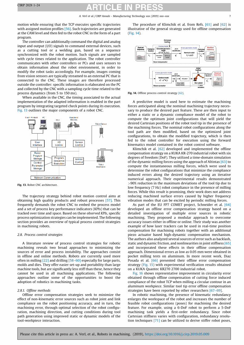
The procedure of Klimchik et al. from Refs. [61] and [62] is
illustrative of the general strategy used for offline compensation
(Fig. 14).
A predictive model is used here to estimate the machining
forces anticipated along the nominal machining trajectory neces-
sary to produce the desired part feature. These are then input to
either a static or a dynamic compliance model of the robot to
compute the optimum joint configurations that will yield the
desired Cartesian positions of the robot tool tip in the presence of
the machining forces. The nominal robot configurations along the
tool path are then modified, based on the optimized joint
configurations, to obtain the modified trajectory, which is then
fed to the robot controller for execution using the forward
kinematics model contained in the robot control software.
Klimchik et al. [62] developed and implemented the offline
compensation strategy on a KUKA KR-270 industrial robot with six
degrees of freedom (DoF). They utilized a time-domain simulation
of the dynamic milling forces using the approach of Altintas [63] to
compute the instantaneous milling forces, which were used to
determine the robot configurations that minimize the compliance
induced errors along the desired trajectory using an iterative
numerical approach. Their experimental results demonstrated
>90% reduction in the maximum deviations of the tool tip due to
low frequency (~7 Hz) robot compliance in the presence of milling
forces. While this result is promising, their work does not address
reducing machined surface errors caused by higher frequency
vibration modes that can be excited by periodic milling forces.
As part of the EU FP7 COMET project, Schneider et al. [64]
developed an offline error compensation strategy based on a
detailed investigation of multiple error sources in robotic
machining. They proposed a modular approach to overcome
accuracy issues either in offline or online. Their study was another
example of how laser trackers can be used in real-time position
compensation for machining robots together with an additional
piezo actuator based high-dynamic compensation mechanism.
The authors also analyzed several sources of error such as backlash,
static and dynamic friction, and nonlinearities in joint stiffness [65]
and incorporated these effects in their offline compensation
approach. Dimensional errors as low as 0.05 mm were obtained in
pocket milling tests on aluminum. In more recent work, Diaz
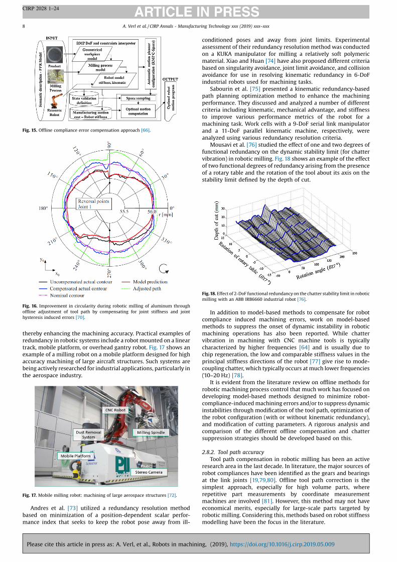
Posada et al. [66] presented their offline error compensation
strategy (Fig. 15) with experimental verification results obtained
on a KUKA Quantec KR270 2700 industrial robot.
Fig. 16 shows representative improvement in circularity error
obtained through offline compensation of cutting force induced
compliance of the robot TCP when milling a circular contour in an
aluminum workpiece. Similar tool tip error offline compensation
strategies have been reported by other researchers [67–69].
In robotic machining, the presence of kinematic redundancy
enlarges the workspace of the robot and increases the number of
feasible robot configurations (poses) for machining the desired
feature. For example, using a 6-DoF robot to perform a 5-DoF
machining task yields a first-order redundancy. Since robot
Cartesian stiffness varies with configuration, redundancy resolu-
tion techniques [71] can be utilized to derive stiffer robot poses,
Fig. 13. Robot CNC architecture.
Fig. 14. Offline process control strategy [62].
A. Verl et al. / CIRP Annals - Manufacturing Technology xxx (2019) xxx–xxx 7
CIRP 2028 1–24
Please cite this article in press as: A. Verl, et al., Robots in machining, (2019), https://doi.org/10.1016/j.cirp.2019.05.009
thereby enhancing the machining accuracy. Practical examples of
redundancy in robotic systems include a robot mounted on a linear
track, mobile platform, or overhead gantry robot. Fig. 17 shows an
example of a milling robot on a mobile platform designed for high
accuracy machining of large aircraft structures. Such systems are
being actively researched for industrial applications, particularly in
the aerospace industry.
Andres et al. [73] utilized a redundancy resolution method
based on minimization of a position-dependent scalar perfor-
mance index that seeks to keep the robot pose away from ill-
conditioned poses and away from joint limits. Experimental
assessment of their redundancy resolution method was conducted
on a KUKA manipulator for milling a relatively soft polymeric
material. Xiao and Huan [74] have also proposed different criteria
based on singularity avoidance, joint limit avoidance, and collision
avoidance for use in resolving kinematic redundancy in 6-DoF
industrial robots used for machining tasks.
Sabourin et al. [75] presented a kinematic redundancy-based
path planning optimization method to enhance the machining
performance. They discussed and analyzed a number of different
criteria including kinematic, mechanical advantage, and stiffness
to improve various performance metrics of the robot for a
machining task. Work cells with a 9-DoF serial link manipulator
and a 11-DoF parallel kinematic machine, respectively, were
analyzed using various redundancy resolution criteria.
Mousavi et al. [76] studied the effect of one and two degrees of
functional redundancy on the dynamic stability limit (for chatter
vibration) in robotic milling. Fig. 18 shows an example of the effect
of two functional degrees of redundancy arising from the presence
of a rotary table and the rotation of the tool about its axis on the
stability limit defined by the depth of cut.
In addition to model-based methods to compensate for robot
compliance induced machining errors, work on model-based
methods to suppress the onset of dynamic instability in robotic
machining operations has also been reported. While chatter
vibration in machining with CNC machine tools is typically
characterized by higher frequencies [64] and is usually due to
chip regeneration, the low and comparable stiffness values in the
principal stiffness directions of the robot [77] give rise to mode-
coupling chatter, which typically occurs at much lower frequencies
(~10–20 Hz) [78].
It is evident from the literature review on offline methods for
robotic machining process control that much work has focused on
developing model-based methods designed to minimize robot-
compliance-induced machining errors and/or to suppress dynamic
instabilities through modification of the tool path, optimization of
the robot configuration (with or without kinematic redundancy),
and modification of cutting parameters. A rigorous analysis and
comparison of the different offline compensation and chatter
suppression strategies should be developed based on this.
2.8.2. Tool path accuracy
Tool path compensation in robotic milling has been an active
research area in the last decade. In literature, the major sources of
robot compliances have been identified as the gears and bearings
at the link joints [19,79,80]. Offline tool path correction is the
simplest approach, especially for high volume parts, where
repetitive part measurements by coordinate measurement
machines are involved [81]. However, this method may not have
economical merits, especially for large-scale parts targeted by
robotic milling. Considering this, methods based on robot stiffness
modelling have been the focus in the literature.
Fig. 15. Offline compliance error compensation approach [66].
Fig. 16. Improvement in circularity during robotic milling of aluminum through
offline adjustment of tool path by compensating for joint stiffness and joint
hysteresis induced errors [70].
Fig. 17. Mobile milling robot: machining of large aerospace structures [72].
Fig.18. Effect of 2-DoF functional redundancy on the chatter stability limit in robotic
milling with an ABB IRB6660 industrial robot [76].
A. Verl et al. / CIRP Annals - Manufacturing Technology xxx (2019) xxx–xxx8
CIRP 2028 1–24
Please cite this article in press as: A. Verl, et al., Robots in machining, (2019), https://doi.org/10.1016/j.cirp.2019.05.009
Belchior et al. [82] applied robotic offline tool path correction
on progressive sheet metal forming process. Barnfather et al.
[83] proposed to use photogrammetry assisted robotic machin-
ing to compensate inaccuracies in robotic milling of two stage
processes. The closest point to the nominal cutting frame on
aligned inspection surface is used as a base for compensation.
Then, the surface dislocation errors generated in the previous
pass are compensated during the finishing pass. It was
demonstrated that accuracy can be increased by using photo-
grammetry assisted compensation. In milling of circular
pockets, the diameter error was decreased from 500 mm down
to 200 mm, whereas cylindricity error was improved from
1000 down to 250 mm.
Zäh and Rösch [84] proposed fuzzy logic-based controllers to
improve the tool path accuracy in robotic milling by compensating
the static deflection of the robot during robotic milling process. In
some applications where increased stiffness is required, 6-axis
parallel kinematic robots are used [85,86]. A drawback of such
solutions is the need for extensive experimental calibration.
In an early study on real time correction of the robot position in
robotic milling, Zhang et al. [87] investigated major topics and
approaches. They proposed real time compensation of robot
deflections and improved the process performance in terms of
accuracy. The results in their study were revolutionary and showed
that robots can exhibit high performance milling through real time
path compensation techniques. Recently, laser tracking systems,
contrary to their high capital investment, have started to be used in
tool path correction for robotic milling applications.
In a later study, Shi et al. [88] used a 3-axis laser tracker for real
time tool path correction. They focused on linear and circular type
tool path geometries, where major improvement was achieved in
tool path accuracy from 2 mm levels to the order of 50 mm.
The second major obstacle in the integration of industrial robots
in milling processes is the low frequency modes introduced by
their flexible structures. High amplitude vibrations that occur at
low frequencies subsequently result in high fluctuations in the
cutting forces. As a result, part surface, tool body, spindle and robot
axis can be damaged.
Addressing dynamics and stability of robotic milling, Pan et al.
[18] were the first to demonstrate the deep marks left on the part
surface by the robot vibrations in robotic milling. Zaghbani et al.
[89] applied a variable spindle speed strategy for vibration control
and minimization in robotic milling, where they used the cutting
force and vibration data as a measure of stability in their statistical
approach. It is shown that spindle speed variation can be used as a
chatter mitigation strategy in robotic milling.
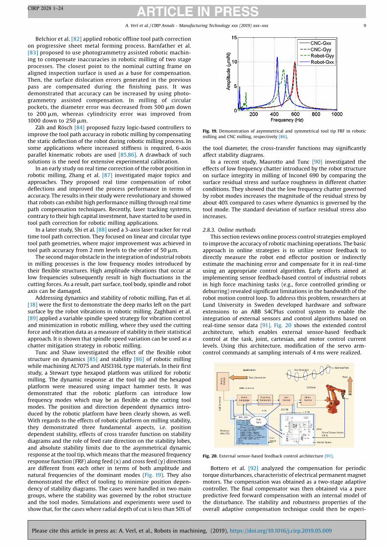
Tunc and Shaw investigated the effect of the flexible robot
structure on dynamics [85] and stability [86] of robotic milling
while machining AL7075 and AISI316L type materials. In their first
study, a Stewart type hexapod platform was utilized for robotic
milling. The dynamic response at the tool tip and the hexapod
platform were measured using impact hammer tests. It was
demonstrated that the robotic platform can introduce low
frequency modes which may be as flexible as the cutting tool
modes. The position and direction dependent dynamics intro-
duced by the robotic platform have been clearly shown, as well.
With regards to the effects of robotic platform on milling stability,
they demonstrated three fundamental aspects, i.e. position
dependent stability, effects of cross transfer function on stability
diagrams and the role of feed rate direction on the stability lobes,
and absolute stability limits due to the asymmetrical dynamic
response at the tool tip, which means that the measured frequency
response function (FRF) along feed (x) and cross feed (y) directions
are different from each other in terms of both amplitude and
natural frequencies of the dominant modes (Fig. 19). They also
demonstrated the effect of tooling to minimize position depen-
dency of stability diagrams. The cases were handled in two main
groups, where the stability was governed by the robot structure
and the tool modes. Simulations and experiments were used to
show that, for the cases where radial depth of cut is less than 50% of
the tool diameter, the cross-transfer functions may significantly
affect stability diagrams.
In a recent study, Maurotto and Tunc [90] investigated the
effects of low frequency chatter introduced by the robot structure
on surface integrity in milling of Inconel 690 by comparing the
surface residual stress and surface roughness in different chatter
conditions. They showed that the low frequency chatter governed
by robot modes increases the magnitude of the residual stress by
about 40% compared to cases where dynamics is governed by the
tool mode. The standard deviation of surface residual stress also
increases.
2.8.3. Online methods
This section reviews online process control strategies employed
to improve the accuracy of robotic machining operations. The basic
approach in online strategies is to utilize sensor feedback to
directly measure the robot end effector position or indirectly
estimate the machining error and compensate for it in real-time
using an appropriate control algorithm. Early efforts aimed at
implementing sensor feedback-based control of industrial robots
in high force machining tasks (e.g., force controlled grinding or
deburring) revealed significant limitations in the bandwidth of the
robot motion control loop. To address this problem, researchers at
Lund University in Sweden developed hardware and software
extensions to an ABB S4CPlus control system to enable the
integration of external sensors and control algorithms based on
real-time sensor data [91]. Fig. 20 shows the extended control
architecture, which enables external sensor-based feedback
control at the task, joint, cartesian, and motor control current
levels. Using this architecture, modification of the servo arm-
control commands at sampling intervals of 4 ms were realized.
Bottero et al. [92] analyzed the compensation for periodic
torque disturbances, characteristic of electrical permanent magnet
motors. The compensation was obtained as a two-stage adaptive
controller. The final compensator was then obtained via a pure
predictive feed forward compensation with an internal model of
the disturbance. The stability and robustness properties of the
overall adaptive compensation technique could then be experi-
Fig. 19. Demonstration of asymmetrical and symmetrical tool tip FRF in robotic
milling and CNC milling, respectively [86].
Fig. 20. External sensor-based feedback control architecture [91].
A. Verl et al. / CIRP Annals - Manufacturing Technology xxx (2019) xxx–xxx 9
CIRP 2028 1–24
Please cite this article in press as: A. Verl, et al., Robots in machining, (2019), https://doi.org/10.1016/j.cirp.2019.05.009

mentally validated on industrial manipulators. Today, industrial
robot controllers come with external sensor interfacing features
(e.g., KUKA RSI [93]) that enable real-time communication
between robot controller and external sensors.
Olsson et al. [94] developed a control architecture to implement
force-controlled drilling of flexible aircraft skin material on an ABB
IRB 2400 IR. A 6-axis force/torque sensor was used to measure the
x–y–z forces and torques produced in drilling. A dynamic model of
the robot response to external forces and moments was used to
design a feedback/feedforward control algorithm that adjusts the
clamp-up force of drilled sheets in real-time. Evidence of reduced
x–y tool deflections was shown, but no direct improvement in hole
quality was found. Pan and Zhang [95] implemented a hybrid
position and force control scheme in an ABB IRC5 robot controller
to improve robotic milling accuracy. An ATI 6-axis force/torque
sensor was used to measure the milling forces in real-time, after
compensating for the spindle and tool. Fig. 21 shows the force
control loop utilized in their work. Corrections were made to the
robot’s nominal position and velocity via the trajectory generator.
The authors implemented real-time robot deformation compen-
sation and reduced workpiece surface error.
Schneider et al. [96] used a series of LEDs and three cameras
(Nikon K600 metrology system) to track robot end effector and
compensate in real-time the error in position by modifying the
joint servo commands based on the measured position error. Using
a PID control algorithm, end effector position control of a KUKA
KR125 IR was achieved at 500 Hz, acceptable for IRs.
Fig. 22 shows the machining error obtained with the position
error control strategy when milling a circular slot in a steel
workpiece. Profile accuracy improvement of over 46% was reported
by the authors of the studies presented in Ref. [96].
Later work by Schneider et al. [97] extended their real-time
position error compensation approach to include a combination of
macro and micro manipulation. A KUKA KR125 industrial robot
was the macro-manipulator used to hold the workpiece, while a 3-
axis translational piezo-actuated system served as the high
bandwidth micro-manipulator on which the milling spindle was
mounted. A parallel-link flexure mechanism enhanced the
dynamic properties of the piezo-actuated micro-manipulator
and to extend the range of compensation in each axis to 0.5
mm. The robot position and orientation in the workspace was
measured at 440 Hz using a metrology system. Fig. 23 shows the
system architecture.
Subsequently, Fig. 24 shows measured profile errors obtained in
machining a circular slot similar to Ref. [96]. The authors indicate
that machining accuracy of �100 mm can be obtained with the
combined macro and micro-manipulator system in milling of steel.
Diaz Posada et al. [98] investigated the improvement in robot
positioning accuracy in robotic drilling using a 3D laser tracker to
compensate for the end effector position and orientation errors,
and a robot compliance model-based compensation implemented
in the external controller interfaced with the robot controller. Their
results show the laser tracker-based compensation is able to
reduce the translation errors to less than 0.1 mm and keep rotation
errors to a maximum of 0.2� in robotic drilling of metal sheets.
Work on real time pose control of an industrial robot using 3-
DoF and 6-DoF laser tracking has also been reported by Moeller
et al. [99]. Fig. 25 shows the positioning path accuracy (ATp) and
the repeatability error (RTp) obtained using external closed loop
control based on the laser tracker data. It can be seen that there is
significant reduction in the ATp parameter with 3- and 6-DoF
control but the improvement in repeatability error is not
significant. However, the external control approach outlined by
Moeller et al. is shown to produce considerable reduction in the
Fig. 21. Force control loop implemented in an ABB IRC5 controller [95].
Fig. 22. Machining error using a tuned PI control algorithm based on real-time end
effector position sensing [96].
Fig. 23. Overall system architecture of the combined macro and micro manipulator
actuated system [97].
Fig. 24. Deviation of the machined outer circle, measured using a coordinate
measurement machine. Setup A: only position-control of the robot. Setup C: micro
and macro manipulation including optical tracking, adapted from [97].
Fig. 25. Path positioning accuracy and robot repeatability error with and without
laser tracker-based control [99].
A. Verl et al. / CIRP Annals - Manufacturing Technology xxx (2019) xxx–xxx10
CIRP 2028 1–24
Please cite this article in press as: A. Verl, et al., Robots in machining, (2019), https://doi.org/10.1016/j.cirp.2019.05.009
robot deflection induced error produced in machining polyure-
thane material.
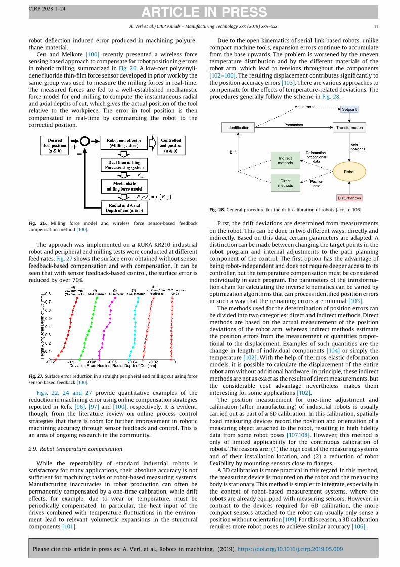
Cen and Melkote [100] recently presented a wireless force
sensing based approach to compensate for robot positioning errors
in robotic milling, summarized in Fig. 26. A low-cost polyvinyli-
dene fluoride thin-film force sensor developed in prior work by the
same group was used to measure the milling forces in real-time.
The measured forces are fed to a well-established mechanistic
force model for end milling to compute the instantaneous radial
and axial depths of cut, which gives the actual position of the tool
relative to the workpiece. The error in tool position is then
compensated in real-time by commanding the robot to the
corrected position.
The approach was implemented on a KUKA KR210 industrial
robot and peripheral end milling tests were conducted at different
feed rates. Fig. 27 shows the surface error obtained without sensor
feedback-based compensation and with compensation. It can be
seen that with sensor feedback-based control, the surface error is
reduced by over 70%.
Figs. 22, 24 and 27 provide quantitative examples of the
reduction in machining error using online compensation strategies
reported in Refs. [96], [97] and [100], respectively. It is evident,
though, from the literature review on online process control
strategies that there is room for further improvement in robotic
machining accuracy through sensor feedback and control. This is
an area of ongoing research in the community.
2.9. Robot temperature compensation
While the repeatability of standard industrial robots is
satisfactory for many applications, their absolute accuracy is not
sufficient for machining tasks or robot-based measuring systems.
Manufacturing inaccuracies in robot production can often be
permanently compensated by a one-time calibration, while drift
effects, for example, due to wear or temperature, must be
periodically compensated. In particular, the heat input of the
drives combined with temperature fluctuations in the environ-
ment lead to relevant volumetric expansions in the structural
components [101].
Due to the open kinematics of serial-link-based robots, unlike
compact machine tools, expansion errors continue to accumulate
from the base upwards. The problem is worsened by the uneven
temperature distribution and by the different materials of the
robot arm, which lead to tensions throughout the components
[102–106]. The resulting displacement contributes significantly to
the position accuracy errors [103]. There are various approaches to
compensate for the effects of temperature-related deviations. The
procedures generally follow the scheme in Fig. 28.
First, the drift deviations are determined from measurements
on the robot. This can be done in two different ways: directly and
indirectly. Based on this data, certain parameters are adapted. A
distinction can be made between changing the target points in the
robot program and internal adjustments to the path planning
component of the control. The first option has the advantage of
being robot-independent and does not require deeper access to its
controller, but the temperature compensation must be considered
individually in each program. The parameters of the transforma-
tion chain for calculating the inverse kinematics can be varied by
optimization algorithms that can process identified position errors
in such a way that the remaining errors are minimal [103].
The methods used for the determination of position errors can
be divided into two categories: direct and indirect methods. Direct
methods are based on the actual measurement of the position
deviations of the robot arm, whereas indirect methods estimate
the position errors from the measurement of quantities propor-
tional to the displacement. Examples of such quantities are the
change in length of individual components [104] or simply the
temperature [102]. With the help of thermos-elastic deformation
models, it is possible to calculate the displacement of the entire
robot arm without additional hardware. In principle, these indirect
methods are not as exact as the results of direct measurements, but
the considerable cost advantage nevertheless makes them
interesting for some applications [102].
The position measurement for one-time adjustment and
calibration (after manufacturing) of industrial robots is usually
carried out as part of a 6D calibration. In this calibration, spatially
fixed measuring devices record the position and orientation of a
measuring object attached to the robot, resulting in high fidelity
data from some robot poses [107,108]. However, this method is
only of limited applicability for the continuous calibration of
robots. The reasons are: (1) the high cost of the measuring systems
and of their installation location, and (2) a reduction of robot
flexibility by mounting sensors close to flanges.
A 3D calibration is more practical in this regard. In this method,
the measuring device is mounted on the robot and the measuring
body is stationary. This method is simpler to integrate, especially in
the context of robot-based measurement systems, where the
robots are already equipped with measuring sensors. However, in
contrast to the devices required for 6D calibration, the more
compact sensors attached to the robot can usually only sense a
position without orientation [109]. For this reason, a 3D calibration
requires more robot poses to achieve similar accuracy [106].
Fig. 26. Milling force model and wireless force sensor-based feedback
compensation method [100].
Fig. 27. Surface error reduction in a straight peripheral end milling cut using force
sensor-based feedback [100].
Fig. 28. General procedure for the drift calibration of robots [acc. to 106].
A. Verl et al. / CIRP Annals - Manufacturing Technology xxx (2019) xxx–xxx 11
CIRP 2028 1–24
Please cite this article in press as: A. Verl, et al., Robots in machining, (2019), https://doi.org/10.1016/j.cirp.2019.05.009

In contrast to absolute calibration, drift compensation or
relative calibration only uses a limited set of recent measurement
values obtained at regular intervals. The robot approaches various
targets on the measuring body and the sensors determine the
position errors. On this basis, certain parameters particularly
susceptible to temperature are optimized to minimize the position
errors [101,103,105,106,109].
In a full calibration, all available targets are scanned and the
compensation values calculated. This method is used after
prolonged plant stops to compensate for substantial temperature
changes. To avoid long pauses during operation, usually only a few
targets are measured between the primary robot operations. These
are subsequently used for calibration together with previously
recorded measuring points, which is why the method is called split
calibration [106]. In the primary application area of this
technology, the robot-based inline measurement of components
for quality assurance, the measurement results of the robot cells
are compared with measurements from coordinate measurement
machines in temperature-controlled environments at regular
intervals. By adding offsets, the discrepancies can be further
reduced.
3. Programming in robotic machining
Until recently, industrial robots were used in machining
exclusively for loading and unloading, that is, for supporting
machine tools in machining processes. But with the possibility of
using them for machining tasks with low process forces, like
chamfering or deburring [110], new requirements emerged for
path planning and thus for the programming of industrial robots
for machining operations. Some of the particularities of this field
are presented in this section, along with practice examples.
3.1. Sensor based programming methods (deburring, polishing)
The application of a stereo camera system for external TCP-pose
measurement increases the absolute positioning accuracy of an
industrial milling robot by up to 0.1 mm [111]. For higher absolute
accuracy up to 0.03 mm and error correction along the tool path
during feed motion, dynamically measuring laser tracker systems
are a suitable solution. External guidance (Fig. 29) makes the
machining robot unsusceptible to external or constant process
forces, thermal expansion and calibration errors [99].
3.2. Programming environment
Pre- and post-operations in machining, such as the determina-
tion of the workpiece’s position and orientation as well as
measurement of the geometry after machining, can be performed
by robots using additional vision- and laser-based technologies.
These operations can be executed using the robot control (RC). For
the machining task itself, the RC has to be complemented with
functions of a CNC, like in machine tools. Thus, the RC and its
advantages can be used for pre- and post-operations but the path
planning and trajectory generation for the machining part is done
by the CNC. This is necessary because the RC is parametrized for the
particular robot that it is commanding and hence, always machine-
specific. CNCs, however, are used to ensure the proper machining
of the workpiece [112]. The combination of RC and NC enables G-
code programming of the machining process. Exploiting the
flexibility of robots in machining G-code programming can be very
complex and challenging. For this reason, the use of CAM-software
is required to ensure simplified and collision free path generation.
3.2.1. CAD-CAM toolchain
The machining of components via CAM path planning usually
starts by loading a CAD file into the editor of the CAM program.
Various standard CAD data formats, such as STEP or IGS, can be
read. After path planning (Fig. 30, Step2) the program can be
exported in standardized or machine specific output formats.
As shown in Fig. 30, the output format can be written into the
respective programming language of the robot manufacturer or
can be an output in G-code adapted for robot applications. The
customized G-code may allow the use of a larger look-ahead, an
extension of the program parser’s look-ahead. Under these
conditions more precise machining results can be achieved. Other
possibilities of increasing the machining accuracy with offline
programming using CAM tools are shown in Refs. [113–116].
In the project PROGEN [117], demonstrators of pressing tools
were machined by robots. Processing was carried out on the same
geometry with the same material. Path planning for the milling
strategies was carried out using the same CAM program in G-code
compilation, but varied in 3- or 5-axis programming. The results of
the milling processes are shown in Fig. 31. The surface color is,
analog to the scale, the deviation of the surface geometry in [mm]
compared to the CAD design. The evaluation shown by a
structured-light 3D scanner reveals that 3-axis machining has
fewer geometry deviations over the entire component. This is
mainly due to the frequent reorientation of the process head in 5-
axis machining and the associated axis movement of the robot. The
processing quality can be influenced by targeted robot poses [118]
and skilled path planning [87]. In addition to the selection of
optimal robot positions, the clamping position, the position of the
tool path and the process-related technology parameters also
determine the process result. Industrial robots with serial
Fig. 29. External TCP-guidance and accuracy validation by two dynamic laser
tracker systems [99].
Fig. 30. Process chain CAD-CAM.
Fig. 31. Results of robot-based milling in 3-axis (left) and 5-axis programming
(right) [117].
A. Verl et al. / CIRP Annals - Manufacturing Technology xxx (2019) xxx–xxx12
CIRP 2028 1–24
Please cite this article in press as: A. Verl, et al., Robots in machining, (2019), https://doi.org/10.1016/j.cirp.2019.05.009
kinematics have a different static and dynamic behavior, depend-
ing on the process parameters [27].
Current CAM planning systems are unable to simulate static and
dynamic properties of robot systems during process design. One
approach was pursued in the publicly funded research project
HORuS (at WZL RWTH Aachen) with a focus on integrating process
behavior into process planning. The follow-up project HORuS2 will
further develop these findings. The main focus is on the
development of planning assistance modules to increase the
accuracy of robot systems for machining large components.
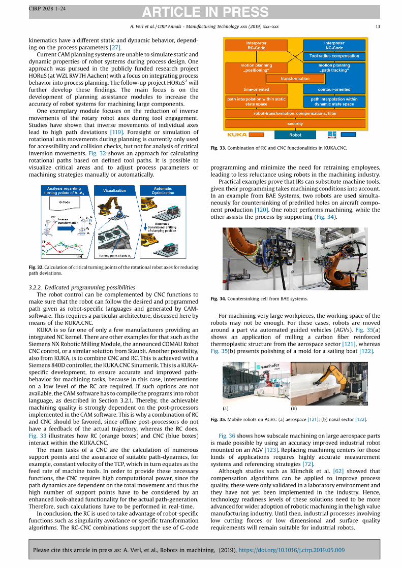
One exemplary module focuses on the reduction of inverse
movements of the rotary robot axes during tool engagement.
Studies have shown that inverse movements of individual axes
lead to high path deviations [119]. Foresight or simulation of
rotational axis movements during planning is currently only used
for accessibility and collision checks, but not for analysis of critical
inversion movements. Fig. 32 shows an approach for calculating
rotational paths based on defined tool paths. It is possible to
visualize critical areas and to adjust process parameters or
machining strategies manually or automatically.
3.2.2. Dedicated programming possibilities
The robot control can be complemented by CNC functions to
make sure that the robot can follow the desired and programmed
path given as robot-specific languages and generated by CAM-
software. This requires a particular architecture, discussed here by
means of the KUKA.CNC.
KUKA is so far one of only a few manufacturers providing an
integrated NC kernel. There are other examples for that such as the
Siemens NX Robotic Milling Module, the announced COMAU Robot
CNC control, or a similar solution from Stäubli. Another possibility,
also from KUKA, is to combine CNC and RC. This is achieved with a
Siemens 840D controller, the KUKA.CNC Sinumerik. This is a KUKA-
specific development, to ensure accurate and improved path-
behavior for machining tasks, because in this case, interventions
on a low level of the RC are required. If such options are not
available, the CAM software has to compile the programs into robot
language, as described in Section 3.2.1. Thereby, the achievable
machining quality is strongly dependent on the post-processors
implemented in the CAM software. This is why a combination of RC
and CNC should be favored, since offline post-processors do not
have a feedback of the actual trajectory, whereas the RC does.
Fig. 33 illustrates how RC (orange boxes) and CNC (blue boxes)
interact within the KUKA.CNC.
The main tasks of a CNC are the calculation of numerous
support points and the assurance of suitable path-dynamics, for
example, constant velocity of the TCP, which in turn equates as the
feed rate of machine tools. In order to provide these necessary
functions, the CNC requires high computational power, since the
path dynamics are dependent on the total movement and thus the
high number of support points have to be considered by an
enhanced look-ahead functionality for the actual path-generation.
Therefore, such calculations have to be performed in real-time.
In conclusion, the RC is used to take advantage of robot-specific
functions such as singularity avoidance or specific transformation
algorithms. The RC-CNC combinations support the use of G-code
programming and minimize the need for retraining employees,
leading to less reluctance using robots in the machining industry.
Practical examples prove that IRs can substitute machine tools,
given their programming takes machining conditions into account.
In an example from BAE Systems, two robots are used simulta-
neously for countersinking of predrilled holes on aircraft compo-
nent production [120]. One robot performs machining, while the
other assists the process by supporting (Fig. 34).
For machining very large workpieces, the working space of the
robots may not be enough. For these cases, robots are moved
around a part via automated guided vehicles (AGVs). Fig. 35(a)
shows an application of milling a carbon fiber reinforced
thermoplastic structure from the aerospace sector [121], whereas
Fig. 35(b) presents polishing of a mold for a sailing boat [122].
Fig. 36 shows how subscale machining on large aerospace parts
is made possible by using an accuracy improved industrial robot
mounted on an AGV [123]. Replacing machining centers for those
kinds of applications requires highly accurate measurement
systems and referencing strategies [72].
Although studies such as Klimchik et al. [62] showed that
compensation algorithms can be applied to improve process
quality, these were only validated in a laboratory environment and
they have not yet been implemented in the industry. Hence,
technology readiness levels of these solutions need to be more
advanced for wider adoption of robotic machining in the high value
manufacturing industry. Until then, industrial processes involving
low cutting forces or low dimensional and surface quality
requirements will remain suitable for industrial robots.
Fig. 32. Calculation of critical turning points of the rotational robot axes for reducing
path deviations.
Fig. 33. Combination of RC and CNC functionalities in KUKA.CNC.
Fig. 34. Countersinking cell from BAE systems.
Fig. 35. Mobile robots on AGVs: (a) aerospace [121]; (b) naval sector [122].
A. Verl et al. / CIRP Annals - Manufacturing Technology xxx (2019) xxx–xxx 13
CIRP 2028 1–24
Please cite this article in press as: A. Verl, et al., Robots in machining, (2019), https://doi.org/10.1016/j.cirp.2019.05.009

4. Machining processes with industrial robots
In this section, we are offering a detailed overview of known
machining processes that benefit from the deployment of
industrial robots. We are also discussing methods of enabling
robots for a wider range of machining applications based on
current studies and research results.
4.1. Deburring
Deburring is a common manufacturing process which demands
characteristics also common to robotic systems (e.g., flexibility or
re-configurability, among others). Robots are still not widely used
for performing this manufacturing task. Several advances have
been made for improving the use of robots in deburring processes.
The offline programming (OLP) allows simulating the process in
virtual environments and automatically generating programs
based on geometric approaches. For example, the use of OLP in
conjunction with a touch probe-based strategy for robotic
deburring of aerospace components [124]. Also, an offline
simulation of finishing edges has been reported as beneficial for
the automation of this process [125].
The problem of accurately localizing the workpiece is solved in
industry mainly by using in-process measurement sensors that
localize the workpiece for a subsequent accurate generation of the
deburring path. For instance, the use of a vision assisted robotic
system using 2D-images for automatic programming has been
proposed in Ref. [126]. In industrial cases, workpiece inaccuracies
are compensated under the allowed tolerance mainly due to the
introduction of compliant tools that compensate surface irregu-
larities while maintaining a defined force. Other compensation
tools such as integrated pneumatic actuation systems have been
proposed for tackling this limitation [127].
Numerous control laws and strategies have been proposed in
order to compensate robot, process, and workpiece errors. The
control methods can be categorized in two major approaches:
impedance control and hybrid position/force control [128]. Exam-
ples of control applications are, for instance: the robot path
generation method using hybrid force and visual servoing for
reducing programming time [129]; tool-path modification based
on direct teaching over the workpiece with a force control in
normal/tangential direction [130]; the control strategy of mimick-
ing human behavior during manual deburring [131].
Despite the previously introduced state of the art, remaining
challenges have to be overcome in order to reduce the negative
effects of the process and to facilitate the implementation of
robotic deburring systems. These challenges are listed below:
� Robot, process, and product dependent tolerances make it
difficult to reach the industry demanded accuracies.
� Robot cell cost efficiency may be limited due to complex settings
and long programming times, especially given changeovers.
� Programming for robot deburring usually demands experts with
further expertise in the process itself [132].
� Burr positions and dimensions are difficult to predict which
makes the process highly variable.
� Additional sensors require specific parameterization, making the
set-up of robot cells complex, especially given workpiece and
process variations.
� The low stiffness of robot systems in comparison with CNC
machines can cause difficulties for achieving high quality
deburring, especially for iron and steel parts.
� The deburring of complex and large workpieces is difficult to
achieve with robots due to the lack of absolute position accuracy.
Due to these challenges, manufacturing programming efforts
and process quality requirements should be carefully investigated
before applying robots in material removal. Robots still offer
advantages: the machined part can be grasped and guided relative
to the spindle, so that a fully automated work cycle is possible.
Furthermore, large workspaces and high tool dexterity could be
made available at a low cost.
4.1.1. Offline compensation of workpiece shape deviations
A fundamental problem affecting the process quality of
deburring processes is that geometric shape deviations between
the nominal CAD model and the manufactured parts may be
beyond acceptable tolerances. To overcome this challenge, Kuss
et al. [133] proposed an approach in which dimensional tolerance
specifications of the manufactured part retrieved from the product
design are then used to derive possible variations of the workpiece
geometry model. The iterative closest point (ICP) algorithm is
applied for identifying matching inaccuracies between CAD-
generated and sensor-derived point clouds. These identified and
modelled inaccuracies are later compensated in an OLP system to
achieve better accuracies. Fig. 37 shows the experimental setup for
the detection of workpiece shape deviations within a robotic
deburring process. Deburring with shape deviations demonstrated
a 57% decrease in the roundness standard deviation error,
compared to deburring without shape deviation recognition.
4.1.2. Automatic OLP for sensor-based robotic deburring
In order to approach the complexity of programming robotic
deburring systems, an automatic OLP for sensor-based robotic
deburring has been proposed, facilitating the industrial imple-
mentation of these systems. Based on the Product, Process, and
Robot (PPR) model, paths are generated which considers the
constraints and DoF’s of the robotic deburring process.
A laser scanner sensor is used for workpiece localization in the
robot cell (Fig. 38). The ICP algorithm is later also used for
compensating errors between the TCP and the edge to be deburred.
Fig. 36. Positioning accuracy in large workspaces [123].
Fig. 37. Detecting workpiece shape deviations with a 3D sensor for robotic
deburring processes (left). Test workpiece after the deburring process with
detection of shape deviations (right) [133]. Key for the left image: 1. Industrial robot
KUKA KR270; 2. Spindle Pferd PWS; 3. Milling tool; 4. Workpiece; 5. 3D sensor
Ensenso N10.
Fig. 38. Sensor-based robotic deburring (left), pre-programmed in an OLP
environment (right) [134].
A. Verl et al. / CIRP Annals - Manufacturing Technology xxx (2019) xxx–xxx14
CIRP 2028 1–24
Please cite this article in press as: A. Verl, et al., Robots in machining, (2019), https://doi.org/10.1016/j.cirp.2019.05.009

Output of this approach is an automatically generated program in
which the expected measurements are also encoded and sent to
the robot controller for later compensation [134]. Furthermore, the
OLP system has been developed to embed sensor models for
measurement optimization, considering sensor specifications and
using sample-based planners and the intrinsic process DoF. Sensor
and tool calibration algorithms have been proposed to provide
satisfactory accuracies [134].
4.2. Incremental forming
In sheet metal forming, conventional processes are unable to
meet the growing demand for shortening product development
cycles due to their need for part dependent tools. Their time and cost
intensive manufacturing prevent a reasonable usage in prototyping
and small batch production [135,136]. The incremental sheet metal
forming (ISF) process is able to overcome these challenges due to its
high geometrical form flexibilityand part independent tools, making
it applicable for a wide range of industries [137–140].
In ISF, the final shape is produced by the incremental infeed of a
hemispherical forming tool in the depth direction, and by its
movement along the contour in the lateral direction on each level
or on a helical path. This process called Roboforming (Fig. 39) can
be executed by industrial robots, taking advantage of their high
flexibility and distribution while losing the stiffness of the often-
used modified CNC-machines [141]. A second supporting tool can
be mounted on a second robot. It moves directly opposed to the
forming tool and generates a predefined gap and force between the
two hemispherical tools. This locally substitutes a die to improve
the accuracy of the formed part [142]. Additional geometric
elements need to be engineered in preparation of the Roboforming
process chain after the target geometry CAD design of the sheet
metal part is developed. These elements enable CAM-based path
planning and the forming of the target geometry from a planar
sheet metal.
The applied CAM system determines the positions where the
forming tool is in contact with the metal surface. A post processing
step is required for robot program generation. All process
parameters (e.g., contact force of the supporting tool) are defined
in this step [144]. The forming of the extended geometry is
executed by the incremental forming machinery. The sheet metal
is then unclamped, annealed and cut down to the initial target
geometry (Fig. 40).
During the execution of the forming process by the two
cooperating industrial robots, the forces at the forming tool reach
around 2000 N, using a typical deep-drawing steel with a sheet
thickness of 1.0 mm. Those forces lead to a significant displace-
ment of the forming tool’s TCP and therefore a poor geometric
accuracy of the produced part. Laurischkat [146] observed a
displacement of the TCP of over 3 mm during the forming process
using two KUKA KR360-1 (Fig. 41).
To ensure a precise forming process, the displacement of the
forming tool needs to be compensated. In literature there are
various approaches to predict the resulting forming forces before
the forming process [147,148]. However, those approaches lack the
needed accuracy to enable a simulation-based compensation,
especially for complex parts [82]. Therefore, an online-compensa-
tion of the robot position, based on the measured forming forces, is
inevitable.
Abele et al. developed a flexible joint multibody dynamics
system model for an industrial robot to describe its behavior based
on the beforehand measured joint stiffnesses [149]. This model
consists of a basic multibody system including the kinematic and
kinetic parameters. The contained standard stiff joints are
extended to flexible joints by the addition of joints in the direction
of motion. Those are coupled to the driven joints by spring and
damper elements. Analogously joints for tilting are added to
describe the tilting behavior of the bearings. This elastic joint
model is implemented into Matlab/Simulink via SimMechanics.
Laurischkat applied this flexible joint multibody system in
Roboforming. The by a force torque sensor measured forming force
is used to calculate the displacement of the TCP during the forming
process. Afterwards, an inverse model is used to adjust the position
via the robot sensor interface (RSI). Laurischkat [146] was able to
improve the path accuracy significantly (Table 1) by using this
approach. The online stiffness compensation is therefore a
significant extension for the applicability of the process entailing
an increase in geometric precision and increasing the formable
sheet thickness making it indispensable in robot-based incremen-
tal sheet forming.
4.3. Grinding and polishing
Polishing of free form parts like turbine blades, dies and molds
constitutes an important percentage of the total production time
Fig. 39. Robot-based incremental sheet forming setup [143].
Fig. 40. Toolchain for robot-based incremental sheet forming [145].
Fig. 41. Forming tool direct displacement, based on forming force [146].
Table 1
Positioning accuracy in robot-based ISF [146].
Sheet thickness
[mm]
Online
compensation
Mean positioning
error [mm]
Errors exceeding
[%]
�0.3 mm �0.6 mm
1.0 No �0.98 83.6 70.0
Yes �0.04 2.9 0.0
1.5 No �1.35 88.3 73.3
Yes �0.08 13.3 1.0
A. Verl et al. / CIRP Annals - Manufacturing Technology xxx (2019) xxx–xxx 15
CIRP 2028 1–24
Please cite this article in press as: A. Verl, et al., Robots in machining, (2019), https://doi.org/10.1016/j.cirp.2019.05.009

(17–29%) [150]. Various industrial parts require polishing as a last
manufacturing step, as the examples in Fig. 42 show.
In polishing, the aim is to improve the surface finish rather than
to alter part geometry or dimensions. Industrial robots are used in
these operations as an alternative to machine tools. Considering
the compliant tools used in polishing, the required motion
accuracy from the articulated robot is not as high as for milling
processes. As long as the robot can orient the end effector
according to the part surface within the work space, it is very
suitable to perform polishing processes. Literature shows studies
on these processes where the major goal is to improve the
efficiency and surface quality. The research has focused on end
effector application, process analysis and path generation.
The design of end effector systems is of great importance in
robotic polishing operations, especially for keeping a steady
contact and consistent contact forces. Takeuchi et al. [152] used an
air-actuated polishing end effector, where the contact force was
adjusted by an interface of a linear roller slide and an air piston
attached between the robot wrist and the tool. Mizugaki et al. [153]
used loose abrasives in robotic polishing with a compliant end
effector attached to a robot controller communicating with a CAD/
CAM system. The efficiency of the system was demonstrated
experimentally by preventing over-polishing at the edges.
In their work on automated process planning, Saito et al. [154]
developed and implemented an expert system to plan the
polishing of die and mold surfaces. Their system was able to
suggest process plans for minimum cycle times, once performance
requirements like surface quality and initial conditions were
provided. The system was dependent on the knowledge of skilled
mold polishers.
Tool path generation is a vital step towards an automated
polishing process. Mizugaki et al. [155] proposed a novel method
that used the planar Peano curve in the xy-plane and its orthogonal
projection onto the free-form surface. They kept the end effector
normal to the part surface considering the robot’s working space.
They concluded that this way, the polishing force can be controlled.
In another study focusing on tool path generation, Tam et al. [156]
succeeded in even tool path generation by addressing only time
efficiency and surface quality issues. They showed that an accuracy
of 0.01 mm can be achieved with robotic polishing of curved
surfaces. Marquez et al. [157] offered a complete solution for
robotic polishing of die-mold surfaces. They used the geometrical
part definition obtained from the CAD model. The advantages of
robotic automation for the manual polishing processes were
clearly shown in terms of time and cost.
Tsai et al. [158] developed a robotic path planning system for
the automated robotic polishing of molds. They utilized the IGES
data format to create the geometric data structure. They then
planned the tool path based on the intrinsic properties of the mold
surface and process requirements. They demonstrated uniform
coverage of the mold surface with satisfactory quality. In a study by
Tsai et al. [159], a uniform material removal approach to improve
automatic mold polishing is proposed. They obtained the mold
surface geometry in the IGES format, which was re-generated in a
NURBS surface model. They considered the intrinsic properties of
the surface by considering the effective contact area along the
polishing path for uniform material removal. The end effector
velocity together with the polishing force were controlled in order
to achieve uniform material removal. They obtained 60% improve-
ment in profile error, and the material removal could be predicted
accurately with an error margin lower than 6%.
For path control, Yang et al. [160] applied shape adaptive
motion control with already integrated part measurement. They
proposed a system containing four main blocks: surface measure-
ment, surface reconstruction, tool trajectory planning, and axis
motion control (Fig. 43). They implemented spatial spectral
analysis in the first block, and proposed an optimal digitizing
frequency. They then performed a spatial spectral B-spline method
for surface reconstruction. In the third block, a motion profile was
initially selected, then the tool locations were determined based on
the reconstructed surface for improved accuracy. A software
package was then developed and implemented in robotic polishing
processes. They demonstrated benefits of the system for polishing
the spherical surface of a doorstop.
Robotic grinding has also been used in manufacturing large
scale hydro turbines by Alstom and Hydro-Quebec. They improved
turbine efficiency by reducing surface roughness. In a related study
of Sabourin et al. [161], the manual grinding process after the 5-
axis milling of hydraulic turbines was robotized to obtain a better
surface finish with less hydrodynamic friction, at a reduced total
cost (Fig. 44). They improved grinding process parameters for a
desired surface waviness and roughness, which was implemented
on a full-scale Francis turbine blade. It was shown that the surface
roughness can be lowered from Ra = 15 mm to Ra = 0.1 mm
reaching a grinding rate of 5 h/m2.
In their work on automated robotic polishing systems, Ryuh
et al. [162] integrated a six DoF articulated industrial robot with a
pneumatic grinding tool controlled by a PC and a robot controller.
They proposed a procedure to provide the path data to the robot.
The data was automatically generated from the NC-data of a
Fig. 42. Robotic polishing of: aluminum rim (left), car bumper (right) [151].
Fig. 43. Automated robotic polishing system [160].
Fig. 44. Automated robotic polishing/grinding system for turbines [161]: Faro laser
tracker used for proximity (left), polishing process (right).
A. Verl et al. / CIRP Annals - Manufacturing Technology xxx (2019) xxx–xxx16
CIRP 2028 1–24
Please cite this article in press as: A. Verl, et al., Robots in machining, (2019), https://doi.org/10.1016/j.cirp.2019.05.009

previous machining process. This was a step forward towards
automatic path planning for robotic polishing processes. They used
an elastic material between the polishing pad and the holder, to
further enhance the performance of the system in terms of the
grinding contact.
In a recent study, Tian et al. [163] investigated solutions to
improve cost and part quality in curved surface polishing. They
established the physical relation between polishing force, robot,
sensor and polishing tool. Then, they modelled the material
removal distribution and combined this model with a suitable path
spacing algorithm. They validated the system performance on
NAK80 steel by showing that constant force control can be
achieved by active and passive compliance force control.
4.4. Enabling industrial robots for specific tasks
The low eigenfrequencies and absolute positioning accuracies
represent disadvantages of industrial robots in machining.
Measurements on a KUKA KR500-2 robot show that the first
eigenfrequency is at 5.5 Hz. Its mode shape is a rotational
deformation between the robot base frame and the rotating
column. This low frequency comes from the poor stiffness in the
gear box of the first joint [164]. During process planning, Denkena
et al. consider the errors resulting from the gear boxes, such as
compliance and backlash [69,165]. They use the results of the
milling process simulation for a teach-less process monitoring. In
the case of robot machining, effects like structural deviation and
backlash are predicted based on the tool path and simulated
cutting forces, and used for offline compensation. The backlash
leads to a positioning error of 175–349 mm, which could be
compensated by robot control. This compensation is still limited,
because current machining state information like tool wear,
clamping and thermal behavior are not regarded. To take process
changes into account, Denkena et al. [164] present an approach for
online compensation of deviations resulting from process forces. A
model was investigated for calculating the pose-dependent
stiffness for each pose. The machining robot is equipped with a
force sensing spindle holder (Fig. 45) to measure process forces
during the cutting operation and to increase process accuracy with
an online compensation of the TCP deviation.
Milling tasks involve significantly higher load forces than
handling and manipulating. This confronts robotic engineering
with problems that have to be solved before industrial robots can
compete with, or at least complement, conventional machine tools
[112]. Due to their dynamic properties and relatively high
compliance, serially linked robot arms are more susceptible to
process forces than comparable machine tools [166]. This can lead
to deflections from the commanded trajectory, and to strong
natural oscillations. Fig. 46 illustrates the consequence of these
two phenomena for a milling application.
The bend of the milled path in the upper part of Fig. 46 indicates
that the end mill has been statically pushed away from its
commanded trajectory. This deviation can be up to several
millimeters, which is why Puzik et al. [167] refer to it as low
trajectory accuracy. The lower part of Fig. 46 shows the result of
dynamic instability: a sufficiently strong force excitation leads to a
natural vibration of the end effector and therefore to waviness
formation on the workpiece surface (chatter marks). Since the
cutting force increases momentarily whenever the end mill cuts
into one of these chatter marks, the robot structure is excited
periodically with one of its eigenfrequencies. The vibrations caused
by this self-excitement can become so strong that the machining
process has to be stopped in order to avoid serious damage to the
machine, the tool, or the workpiece [168]. Despite these qualitative
shortcomings of milling robots compared to machine tools, their
flexible applicability and their lower investment costs motivate a
division of work: a milling robot processes a workpiece as much as
possible, and then a machine tool performs the finishing. The latter
can be used more efficiently and more profitably this way
[112,169].
Several research studies aim to improve the accuracy, the
vibration behavior and the achievable quality of milling results of
industrial robots. To increase the kinematic stiffness and thereby
the static stability, mechanical reinforcements are widespread.
Machining robots with an increased degree of parallelism are
already available on the market (e.g., ABB IRB 6660). Designing the
spindle as a sixth axis and removing one axis and its compliance
from the flux of forces is another constructional approach to the
problem of static compliance-related errors [170]. These measures
can improve the static and dynamic properties of robots, but
reduce the usable workspace and the kinematic flexibility [84].
A common way to deal with instabilities and inaccuracies is the
implementation of mathematical models for the offline simulation
of different robot structure reactions. Kurze [171] proposed a
model-based method to improve path accuracy and disturbance
behavior. Since the model stiffness and damping parameters have
been determined by analyzing free oscillations in only one pose,
the results have been classified as not satisfactory by the author.
Other works carried out experiments in various poses to determine
the static compliances and use the measurement results to derive
analytical models of the robot [118,172].
The common problem faced by model-based approaches is the
dependency of static and dynamic properties on the robot’s joint
configuration [27,38,173]. Due to system complexity given by
numerous joints and components, this interdependency is
insufficiently described by a mathematical model [174]. Robot
dynamics models are therefore either valid for just a small section
of the workspace or insufficiently consider nonlinearities [175]. Re-
cent studies attempt to identify the pose (end effector cartesian
position and orientation) in an empirical dependency on process
stability, with a high number of measurements conducted in
different machining poses throughout the workspace. For this
purpose, research groups carried out milling experiments in nine
different poses in the xz-plane (y = 0 mm) of the workspace with
feed in positive and negative x and y-direction, as seen in Fig. 47.
Milling wedges with linearly increasing cutting depth gives
information about the correlation between depth of cut and
processing stability. Oscillations of the robot structure are recorded
with a force-sensing plate underneath the workpiece, and
Fig. 45. Force sensing spindle holder for a KUKA KR 500-2 milling robot.
Fig. 46. Static deformation and dynamic instability when milling with robots [38].
A. Verl et al. / CIRP Annals - Manufacturing Technology xxx (2019) xxx–xxx 17
CIRP 2028 1–24
Please cite this article in press as: A. Verl, et al., Robots in machining, (2019), https://doi.org/10.1016/j.cirp.2019.05.009

acceleration sensors on the robot arm. The measurements lead to
the following conclusions: (1) The robot has a strong dependency
on the static and dynamic behavior of the machining pose and the
feed direction. Further experimental investigations in this field are
necessary. (2) An exclusive consideration of robot compliance
values, as it has been assumed in many previous approaches, will
be unsuccessful: for some machining poses, milling quality and
process stability are higher, even though the robot structure is
especially compliant for these joint configurations. Such
approaches require a high amount of measurement and workload,
but they yield promising results.
5. Trends in robotic machining
Having set the scope for deploying industrial robots in
machining processes, we are now focusing in this chapter on
other fields of applications for robots in machining.
5.1. Thin wall machining
Robotic assisted machining is particularly beneficial for thin
wall parts, where problems such as high form errors and chatter
are very common. Ozturk et al. [176] demonstrated the use of
mobile rubber roller support that follows the feed motion of the
machine tool. The rubber roller on the robot applies both support
force and provides additional damping to the part. Hence, the
maximum form error was decreased from 90 to 29 mm in a
representative case (Fig. 48).
Moreover, chatter problems experienced in the center of the
part were eliminated, resulting in an improved surface quality
(Fig. 49).
Support can be provided by different end effectors, such as
rubber rollers and metal castors, which follow the feed motion of
the machine tool. A dexterous hand can also be used as an
additional support in order to increase the dynamic stiffness of the
part (Fig. 50).
As both machine tool and robot are in motion during the
process, there is a risk of collision between them. For this reason,
the integration of the machine tool control and robot control needs
to be established to achieve synchronous motion.
5.2. Dedicated kinematics
Machine tool productivity of industrial robots is still limited by
the dynamic properties, as they influence the process stability.
These influences cannot be compensated with robot control
because the ability to control the joint dynamics is limited by the
cycle time of the robot control. One solution is the optimization of
the whole robot kinematic chain and also of the drive concept.
Denkena et al. [177] proposed an analytical comparison of three
different machine kinematics (Fig. 51). The main objective was the
development of a new cost-efficient machine tool for milling large
aluminum and carbon fiber reinforced thermoplastic (CFRP) parts.
The first concept is based on a serial kinematic. As the sixth joint
is not required for five-sided machining, it is eliminated. For the
second concept, a translational axis is used instead of the first
rotational axis. This drives the whole robot kinematic chain,
increasing the work space and decreasing the required length of
the links. In the third concept, the linear axis actuates the
workpiece table instead of the robotic arm kinematic chain. A
rotational axis of the robotic kinematic chain is replaced by a rotary
table. The replacement of the first rotational axis increases the
stiffness by up to 35%, while the replacement of the guiding shoes
on the next larger model has an insignificant influence. The third
concept is the best solution for higher productivity, but is also more
expensive. The second concept is useful when an inexpensive
machine with optimized stiffness is required. Fig. 52 shows an
analysis of the influence of machine components on the stiffness at
the robot TCP.
Fig. 47. Milling pattern (left) and machining poses [27].
Fig. 48. Improvement in form error with the support.
Fig. 49. Improvement in surface quality Ra with the support.
Fig. 50. Robotic hand support on a thin wall part.
Fig. 51. Concepts and evaluation of machine tool kinematics [177].
A. Verl et al. / CIRP Annals - Manufacturing Technology xxx (2019) xxx–xxx18
CIRP 2028 1–24
Please cite this article in press as: A. Verl, et al., Robots in machining, (2019), https://doi.org/10.1016/j.cirp.2019.05.009
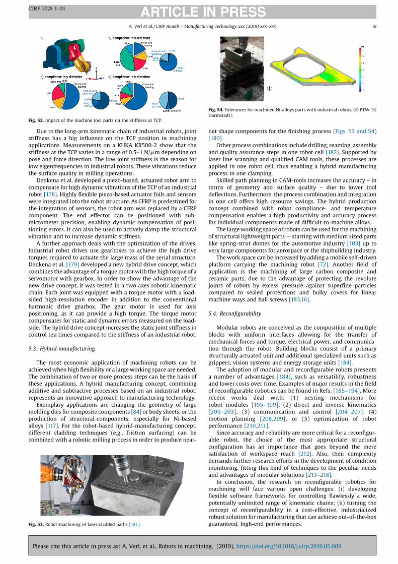
Due to the long-arm kinematic chain of industrial robots, joint
stiffness has a big influence on the TCP position in machining
applications. Measurements on a KUKA KR500-2 show that the
stiffness at the TCP varies in a range of 0.5–1 N/mm depending on
pose and force direction. The low joint stiffness is the reason for
low eigenfrequencies in industrial robots. These vibrations reduce
the surface quality in milling operations.
Denkena et al. developed a piezo-based, actuated robot arm to
compensate for high dynamic vibrations of the TCP of an industrial
robot [178]. Highly flexible piezo-based actuator foils and sensors
were integrated into the robot structure. As CFRP is predestined for
the integration of sensors, the robot arm was replaced by a CFRP
component. The end effector can be positioned with sub-
micrometer precision, enabling dynamic compensation of posi-
tioning errors. It can also be used to actively damp the structural
vibration and to increase dynamic stiffness.
A further approach deals with the optimization of the drives.
Industrial robot drives use gearboxes to achieve the high drive
torques required to actuate the large mass of the serial structure.
Denkena et al. [179] developed a new hybrid drive concept, which
combines the advantage of a torque motor with the high torque of a
servomotor with gearbox. In order to show the advantage of the
new drive concept, it was tested in a two axes robotic kinematic
chain. Each joint was equipped with a torque motor with a load-
sided high-resolution encoder in addition to the conventional
harmonic drive gearbox. The gear motor is used for axis
positioning, as it can provide a high torque. The torque motor
compensates for static and dynamic errors measured on the load-
side. The hybrid drive concept increases the static joint stiffness in
control ten times compared to the stiffness of an industrial robot.
5.3. Hybrid manufacturing
The most economic application of machining robots can be
achieved when high flexibility or a large working space are needed.
The combination of two or more process steps can be the basis of
these applications. A hybrid manufacturing concept, combining
additive and subtractive processes based on an industrial robot,
represents an innovative approach to manufacturing technology.
Exemplary applications are changing the geometry of large
molding dies for composite components [84] or body sheets, or the
production of structural-components, especially for Ni-based
alloys [117]. For the robot-based hybrid-manufacturing concept,
different cladding techniques (e.g., friction surfacing) can be
combined with a robotic milling process in order to produce near-
net shape components for the finishing process (Figs. 53 and 54)
[180].
Other process combinations include drilling, reaming, assembly
and quality assurance steps in one robot cell [182]. Supported by
laser line scanning and qualified CAM tools, these processes are
applied in one robot cell, thus enabling a hybrid manufacturing
process in one clamping.
Skilled path planning in CAM-tools increases the accuracy – in
terms of geometry and surface quality – due to lower tool
deflections. Furthermore, the process combination and integration
in one cell offers high resource savings. The hybrid production
concept combined with robot compliance- and temperature
compensation enables a high productivity and accuracy process
for individual components made of difficult-to-machine alloys.
The large working space of robots can be used for the machining
of structural lightweight parts — starting with medium sized parts
like spring-strut domes for the automotive industry [103] up to
very large components for aerospace or the shipbuilding industry.
The work space can be increased by adding a mobile self-driven
platform carrying the machining robot [72]. Another field of
application is the machining of large carbon composite and
ceramic parts, due to the advantage of protecting the revolute
joints of robots by excess pressure against superfine particles
compared to sealed protections and bulky covers for linear
machine ways and ball screws [183,16].
5.4. Reconfigurability
Modular robots are conceived as the composition of multiple
blocks with uniform interfaces allowing for the transfer of
mechanical forces and torque, electrical power, and communica-
tion through the robot. Building blocks consist of a primary
structurally actuated unit and additional specialized units such as
grippers, vision systems and energy storage units [184].
The adoption of modular and reconfigurable robots presents
a number of advantages [184], such as versatility, robustness
and lower costs over time. Examples of major results in the field
of reconfigurable robotics can be found in Refs. [185–194]. More
recent works deal with: (1) nesting mechanisms for
robot modules [195–199]; (2) direct and inverse kinematics
[200–203]; (3) communication and control [204–207]; (4)
motion planning [208,209]; or (5) optimization of robot
performance [210,211].
Since accuracy and reliability are more critical for a reconfigur-
able robot, the choice of the most appropriate structural
configuration has an importance that goes beyond the mere
satisfaction of workspace reach [212]. Also, their complexity
demands further research efforts in the development of condition
monitoring, fitting this kind of techniques to the peculiar needs
and advantages of modular solutions [213–218].
In conclusion, the research on reconfigurable robotics for
machining will face various open challenges: (i) developing
flexible software frameworks for controlling flawlessly a wide,
potentially unlimited range of kinematic chains; (ii) turning the
concept of reconfigurability in a cost-effective, industrialized
robust solution for manufacturing that can achieve out-of-the-box
guaranteed, high-end performances.
Fig. 52. Impact of the machine tool parts on the stiffness at TCP.
Fig. 53. Robot-machining of laser-cladded paths [181].
Fig. 54. Tolerances for machined Ni-alloys parts with industrial robots. (© PTW TU
Darmstadt).
A. Verl et al. / CIRP Annals - Manufacturing Technology xxx (2019) xxx–xxx 19
CIRP 2028 1–24
Please cite this article in press as: A. Verl, et al., Robots in machining, (2019), https://doi.org/10.1016/j.cirp.2019.05.009

5.5. Robot programming with function blocks
As of today, the three main available robot programming
methods are: lead-through programming with a teach pendant,
walk-through programming by guiding the robot at its end-
effector, and offline programming with a CAM software.
A novel approach is function block programming. It bridges the
gap between task planning systems and execution systems, and
empowers robot controllers with intelligence. Whilst more
common in human-robot-collaboration applications, it can also
provide an additional advantage in robot machining. In function
block programming, a non-linear task sequence plan can be
mapped automatically to a set of function blocks, which can be
readily dispatched to a chosen robot controller for task execution.
The embedded algorithms of the function blocks are triggered
inside the robot controller to accomplish the planned tasks.
Feedback from human workers is processed and passed to the
function blocks at the robot side for timely robot control.
A function blocks-based automation architecture differs from its
classical counterparts as it enables adaptiveness at multiple levels.
This ensures coping with high rates of component malfunctioning
and handling complex system behavior and dynamics based on the
co-ordination of a rich set of signals. Such adaptiveness, both
architectural and behavioral, is driven by a need to accommodate
external and internal changes, either deterministic or unpredictable.
Each function block contains the control algorithms ruling the
behaviorof the resourcesatdifferent levels inthe automationsystem
from a single control loop uptothe supervisionandplanninglevels. A
robotics example can be seen in Fig. 55.
In robotic applications, examples of function blocks can be
elementary functions such as “move to” or “load tool_ID”, that can
be implemented to populate a library of tasks, up to more complex
functions addressing the process recipes and sequence of
manufacturing tasks. These function blocks are then sequenced
in a task schedule to execute specific machining processes such as
the polishing example reported in Ref. [219].
5.6. AI in machines and collaborative robots
The new generation of industrial robots will need to embed
highly advanced control systems, and be able to autonomously
adapt to unexpected situations including performance degrada-
tion. This can be achieved by adapting the motion parameters. This
typically limits their joint performance by reducing the most
relevant factors (e.g., acceleration, speed, and deceleration). Path
planning adaptation alternatively allows to reduce the movement
of the degraded joints as much as possible by recomputing
trajectories. Artificial intelligence (AI) techniques such as machine
learning and reinforcement learning frameworks can be developed
to allow task experts without AI or programming expertise to teach
the robots their initial task and then support their continuous
learning over the robot’s deployment. The goal is to enable
autonomous robots to learn a large repertoire of behavioral skills
with minimal human intervention. However, robotic AI applica-
tions often compromise the autonomy of the learning process in
favor of achieving training times. This typically involves introduc-
ing hand-engineered logic representations and human demon-
strations. In robotic learning, research work has explored model-
based and model-free learning algorithms.
Model-based algorithms include a variety of dynamics estima-
tion schemes [220] such as Gaussian processes, mixture models,
and local linear system estimation. Deep neural network policies
have been combined with model-based learning in the context of
guided policy search algorithms [221,222]. Such approaches are
exploited for example for scenarios demanding close coordination
between vision and control (developing policies that map raw
image observations directly to torques at the robot's motors), or in
general in situations where it is necessary to learn complex
feedback control policies mapping high-dimensional sensory
inputs to motor torques.
Model-free algorithms include policy search [223] and function
approximation methods [224] that have recently been combined
with deep neural networks for learning complex tasks [225]. Direct
policy gradient methods offer the benefit of unbiased gradient
estimates, but tend to require more experience, since on-policy
estimators preclude reuse of past data.
In manufacturing, machine learning can serve an additional role
in design and optimization of processes [226–229], but demands
future research on real-time processing and control. In current
applications, the robot motion strategy and machining parameters
are adapted in real time based on a sensing system supporting in-
process data collection, their fusion and interpretation. The
optimization logics rely on specific reference quality KPIs. Any
anomalous behavior corresponding to the violation of the quality
indicators results in triggering the optimization model and
enabling the process adaptation logic. The optimization model
can be designed based on various techniques, including AI. Future
works will also consider non-time-critical functions and particu-
larly additional awareness and computational power [230].
6. Conclusions
An increasing role of robots in manufacturing is noticeable,
especially in machining, as exemplified throughout this paper. We
have outlined and investigated opportunities of exploiting the
advantages of robots in this area. One of the trends in robotic
manufacturing is the implementation of accurate and easy-to-use
intuitive programmable systems. The approaches presented in
chapter 4 are examples of such systems. Based on this trend and
the remaining challenges, future directions in this field could be:
� Simulation of robotic systems could be interfaced with analytical
or numerical models to compute robot motion adaptations for
increased tool path accuracy.
� Accessible implementation of robot systems with intrinsic
sensors (i.e. force/torque or vision) capable of automatically
adapting motions in respect to the machining task, thus enabling
improved process control.
� The path planning process could be optimized using process
redundancy for improving the process quality.
� After automatically checking product quality, machine learning
algorithms for process optimization could be offered in a cloud-
service platform.
� Development of input devices for facilitating the programming
experience. Such devices could record process characteristics
and update these in robot systems. Furthermore, robot systems
could learn and be trained by mimicking professional workers.
This paper addresses these challenges and shows how they can
be overcome for a wider implementation of robots in machining.
Fig. 55. Function block distributed control architecture of the robotic cell.
A. Verl et al. / CIRP Annals - Manufacturing Technology xxx (2019) xxx–xxx20
CIRP 2028 1–24
Please cite this article in press as: A. Verl, et al., Robots in machining, (2019), https://doi.org/10.1016/j.cirp.2019.05.009
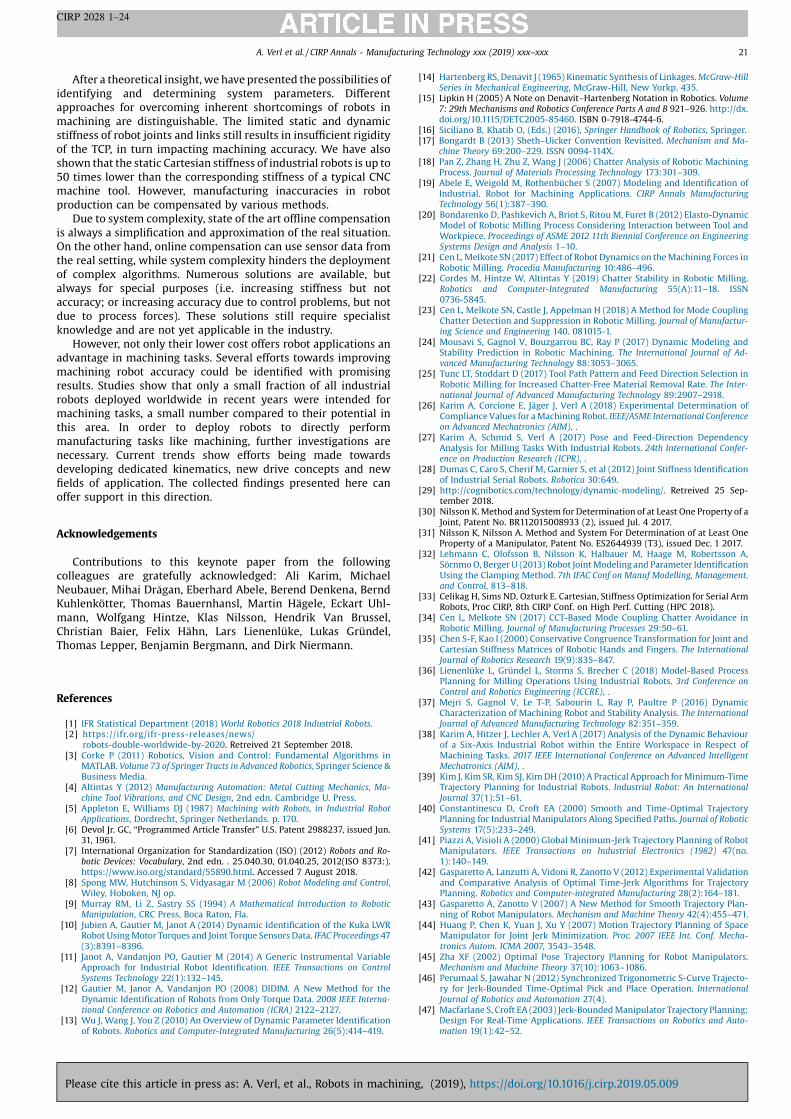
After a theoretical insight, we have presented the possibilities of
identifying and determining system parameters. Different
approaches for overcoming inherent shortcomings of robots in
machining are distinguishable. The limited static and dynamic
stiffness of robot joints and links still results in insufficient rigidity
of the TCP, in turn impacting machining accuracy. We have also
shown that the static Cartesian stiffness of industrial robots is up to
50 times lower than the corresponding stiffness of a typical CNC
machine tool. However, manufacturing inaccuracies in robot
production can be compensated by various methods.
Due to system complexity, state of the art offline compensation
is always a simplification and approximation of the real situation.
On the other hand, online compensation can use sensor data from
the real setting, while system complexity hinders the deployment
of complex algorithms. Numerous solutions are available, but
always for special purposes (i.e. increasing stiffness but not
accuracy; or increasing accuracy due to control problems, but not
due to process forces). These solutions still require specialist
knowledge and are not yet applicable in the industry.
However, not only their lower cost offers robot applications an
advantage in machining tasks. Several efforts towards improving
machining robot accuracy could be identified with promising
results. Studies show that only a small fraction of all industrial
robots deployed worldwide in recent years were intended for
machining tasks, a small number compared to their potential in
this area. In order to deploy robots to directly perform
manufacturing tasks like machining, further investigations are
necessary. Current trends show efforts being made towards
developing dedicated kinematics, new drive concepts and new
fields of application. The collected findings presented here can
offer support in this direction.
Acknowledgements
Contributions to this keynote paper from the following
colleagues are gratefully acknowledged: Ali Karim, Michael
Neubauer, Mihai Dr�agan, Eberhard Abele, Berend Denkena, Bernd
Kuhlenkötter, Thomas Bauernhansl, Martin Hägele, Eckart Uhl-
mann, Wolfgang Hintze, Klas Nilsson, Hendrik Van Brussel,
Christian Baier, Felix Hähn, Lars Lienenlüke, Lukas Gründel,
Thomas Lepper, Benjamin Bergmann, and Dirk Niermann.
References
[1] IFR Statistical Department (2018) World Robotics 2018 Industrial Robots.[2] https://ifr.org/ifr-press-releases/news/
robots-double-worldwide-by-2020. Retreived 21 September 2018.[3] Corke P (2011) Robotics, Vision and Control: Fundamental Algorithms in
MATLAB. Volume 73 of Springer Tracts in Advanced Robotics, Springer Science &Business Media.
[4] Altintas Y (2012) Manufacturing Automation: Metal Cutting Mechanics, Ma-
chine Tool Vibrations, and CNC Design, 2nd edn. Cambridge U. Press.[5] Appleton E, Williams DJ (1987) Machining with Robots, in Industrial Robot
Applications, Dordrecht, Springer Netherlands. p. 170.[6] Devol Jr. GC, “Programmed Article Transfer” U.S. Patent 2988237, issued Jun.
31, 1961.[7] International Organization for Standardization (ISO) (2012) Robots and Ro-
botic Devices: Vocabulary, 2nd edn. . 25.040.30, 01.040.25, 2012(ISO 8373:).https://www.iso.org/standard/55890.html. Accessed 7 August 2018.
[8] Spong MW, Hutchinson S, Vidyasagar M (2006) Robot Modeling and Control,Wiley, Hoboken, NJ op.
[9] Murray RM, Li Z, Sastry SS (1994) A Mathematical Introduction to RoboticManipulation, CRC Press, Boca Raton, Fla.
[10] Jubien A, Gautier M, Janot A (2014) Dynamic Identification of the Kuka LWRRobot Using Motor Torques and Joint Torque Sensors Data. IFAC Proceedings 47(3):8391–8396.
[11] Janot A, Vandanjon PO, Gautier M (2014) A Generic Instrumental VariableApproach for Industrial Robot Identification. IEEE Transactions on Control
Systems Technology 22(1):132–145.[12] Gautier M, Janor A, Vandanjon PO (2008) DIDIM. A New Method for the
Dynamic Identification of Robots from Only Torque Data. 2008 IEEE Interna-
tional Conference on Robotics and Automation (ICRA) 2122–2127.[13] Wu J, Wang J, You Z (2010) An Overview of Dynamic Parameter Identification
of Robots. Robotics and Computer-Integrated Manufacturing 26(5):414–419.
[14] Hartenberg RS, Denavit J (1965) Kinematic Synthesis of Linkages. McGraw-Hill
Series in Mechanical Engineering, McGraw-Hill, New Yorkp. 435.[15] Lipkin H (2005) A Note on Denavit–Hartenberg Notation in Robotics. Volume
7: 29th Mechanisms and Robotics Conference Parts A and B 921–926. http://dx.doi.org/10.1115/DETC2005-85460. ISBN 0-7918-4744-6.
[16] Siciliano B, Khatib O, (Eds.) (2016), Springer Handbook of Robotics, Springer.[17] Bongardt B (2013) Sheth–Uicker Convention Revisited. Mechanism and Ma-
chine Theory 69:200–229. ISSN 0094-114X.[18] Pan Z, Zhang H, Zhu Z, Wang J (2006) Chatter Analysis of Robotic Machining
Process. Journal of Materials Processing Technology 173:301–309.[19] Abele E, Weigold M, Rothenbücher S (2007) Modeling and Identification of
Industrial. Robot for Machining Applications. CIRP Annals ManufacturingTechnology 56(1):387–390.
[20] Bondarenko D, Pashkevich A, Briot S, Ritou M, Furet B (2012) Elasto-DynamicModel of Robotic Milling Process Considering Interaction between Tool andWorkpiece. Proceedings of ASME 2012 11th Biennial Conference on EngineeringSystems Design and Analysis 1–10.
[21] Cen L, Melkote SN (2017) Effect of Robot Dynamics on the Machining Forces inRobotic Milling. Procedia Manufacturing 10:486–496.
[22] Cordes M, Hintze W, Altintas Y (2019) Chatter Stability in Robotic Milling.Robotics and Computer-Integrated Manufacturing 55(A):11–18. ISSN0736-5845.
[23] Cen L, Melkote SN, Castle J, Appelman H (2018) A Method for Mode CouplingChatter Detection and Suppression in Robotic Milling. Journal of Manufactur-ing Science and Engineering 140. 081015-1.
[24] Mousavi S, Gagnol V, Bouzgarrou BC, Ray P (2017) Dynamic Modeling andStability Prediction in Robotic Machining. The International Journal of Ad-
vanced Manufacturing Technology 88:3053–3065.[25] Tunc LT, Stoddart D (2017) Tool Path Pattern and Feed Direction Selection in
Robotic Milling for Increased Chatter-Free Material Removal Rate. The Inter-
national Journal of Advanced Manufacturing Technology 89:2907–2918.[26] Karim A, Corcione E, Jäger J, Verl A (2018) Experimental Determination of
Compliance Values for a Machining Robot. IEEE/ASME International Conferenceon Advanced Mechatronics (AIM), .
[27] Karim A, Schmid S, Verl A (2017) Pose and Feed-Direction DependencyAnalysis for Milling Tasks With Industrial Robots. 24th International Confer-ence on Production Research (ICPR), .
[28] Dumas C, Caro S, Cherif M, Garnier S, et al (2012) Joint Stiffness Identificationof Industrial Serial Robots. Robotica 30:649.
[29] http://cognibotics.com/technology/dynamic-modeling/. Retreived 25 Sep-tember 2018.
[30] Nilsson K. Method and System for Determination of at Least One Property of aJoint, Patent No. BR112015008933 (2), issued Jul. 4 2017.
[31] Nilsson K, Nilsson A. Method and System For Determination of at Least OneProperty of a Manipulator, Patent No. ES2644939 (T3), issued Dec. 1 2017.
[32] Lehmann C, Olofsson B, Nilsson K, Halbauer M, Haage M, Robertsson A,Sörnmo O, Berger U (2013) Robot Joint Modeling and Parameter IdentificationUsing the Clamping Method. 7th IFAC Conf on Manuf Modelling, Management,and Control, 813–818.
[33] Celikag H, Sims ND, Ozturk E. Cartesian, Stiffness Optimization for Serial ArmRobots, Proc CIRP, 8th CIRP Conf. on High Perf. Cutting (HPC 2018).
[34] Cen L, Melkote SN (2017) CCT-Based Mode Coupling Chatter Avoidance inRobotic Milling. Journal of Manufacturing Processes 29:50–61.
[35] Chen S-F, Kao I (2000) Conservative Congruence Transformation for Joint andCartesian Stiffness Matrices of Robotic Hands and Fingers. The InternationalJournal of Robotics Research 19(9):835–847.
[36] Lienenlüke L, Gründel L, Storms S, Brecher C (2018) Model-Based ProcessPlanning for Milling Operations Using Industrial Robots. 3rd Conference on
Control and Robotics Engineering (ICCRE), .[37] Mejri S, Gagnol V, Le T-P, Sabourin L, Ray P, Paultre P (2016) Dynamic
Characterization of Machining Robot and Stability Analysis. The International
Journal of Advanced Manufacturing Technology 82:351–359.[38] Karim A, Hitzer J, Lechler A, Verl A (2017) Analysis of the Dynamic Behaviour
of a Six-Axis Industrial Robot within the Entire Workspace in Respect ofMachining Tasks. 2017 IEEE International Conference on Advanced IntelligentMechatronics (AIM), .
[39] Kim J, Kim SR, Kim SJ, Kim DH (2010) A Practical Approach for Minimum-TimeTrajectory Planning for Industrial Robots. Industrial Robot: An International
Journal 37(1):51–61.[40] Constantinescu D, Croft EA (2000) Smooth and Time-Optimal Trajectory
Planning for Industrial Manipulators Along Specified Paths. Journal of Robotic
Systems 17(5):233–249.[41] Piazzi A, Visioli A (2000) Global Minimum-Jerk Trajectory Planning of Robot
Manipulators. IEEE Transactions on Industrial Electronics (1982) 47(no.1):140–149.
[42] Gasparetto A, Lanzutti A, Vidoni R, Zanotto V (2012) Experimental Validationand Comparative Analysis of Optimal Time-Jerk Algorithms for TrajectoryPlanning. Robotics and Computer-integrated Manufacturing 28(2):164–181.
[43] Gasparetto A, Zanotto V (2007) A New Method for Smooth Trajectory Plan-ning of Robot Manipulators. Mechanism and Machine Theory 42(4):455–471.
[44] Huang P, Chen K, Yuan J, Xu Y (2007) Motion Trajectory Planning of SpaceManipulator for Joint Jerk Minimization. Proc. 2007 IEEE Int. Conf. Mecha-
tronics Autom. ICMA 2007, 3543–3548.[45] Zha XF (2002) Optimal Pose Trajectory Planning for Robot Manipulators.
Mechanism and Machine Theory 37(10):1063–1086.[46] Perumaal S, Jawahar N (2012) Synchronized Trigonometric S-Curve Trajecto-
ry for Jerk-Bounded Time-Optimal Pick and Place Operation. International
Journal of Robotics and Automation 27(4).[47] Macfarlane S, Croft EA (2003) Jerk-Bounded Manipulator Trajectory Planning:
Design For Real-Time Applications. IEEE Transactions on Robotics and Auto-
mation 19(1):42–52.
A. Verl et al. / CIRP Annals - Manufacturing Technology xxx (2019) xxx–xxx 21
CIRP 2028 1–24
Please cite this article in press as: A. Verl, et al., Robots in machining, (2019), https://doi.org/10.1016/j.cirp.2019.05.009

[48] Nguyen KD, Ng TC, Chen IM (2008) On Algorithms for Planning S-CurveMotion Profiles. International Journal of Advanced Robotic Systems 5(1):99–106.
[49] Porawagama CD, Munasinghe SR (2014) Reduced Jerk Joint Space TrajectoryPlanning Method Using 5-3-5 Spline for Robot Manipulators. 7th International
Conference on Information and Automation for Sustainability, 1–6.[50] Rossi C, Savino S (2013) Robot Trajectory Planning by Assigning Positions and
Tangential Velocities. Robotics and Computer-Integrated Manufacturing 29(1):139–156.
[51] Avram O, Valente A (2016) Trajectory Planning for Reconfigurable IndustrialRobots Designed to Operate in a High Precision Manufacturing Industry. 49th
CIRP Conference on Manufacturing Systems (CIRP-CMS 2016), .[52] Valente A, Baraldo S, Carpanzano E (2017) Smooth Trajectory Generation for
Industrial Robots Performing High Precision Assembly Processes. CIRP AnnalsManufacturing Technology 66(1):17–20.
[53] Baraldo S, Valente A (2017) Smooth Joint Motion Planning for High PrecisionReconfigurable Robot Manipulators. 2017 IEEE International Conference on
Robotics and Automation (ICRA), 845–850.[54] Saboori A, et al (2018) The Capacity of Cold Spray Additive Manufacturing
Technology for Metallic Part Repairing. Euro PM2018, . Submitted.[55] Mekaouche A, Chapelle F, Balandraud X (2015) FEM-Based Generation of
Stiffness Maps. IEEE Transactions on Robotics 31(1):217–222.[56] Nof SY, (Ed.) (1999), Handbook of Industrial Robotics. 2nd ed. ISBN: 978-0-471-
17783-8.[57] Asada H, Slotine JJE (1992) Robot Analysis and Control, John Wiley & Sons, Inc.,
New York, NY, USA. ISBN:0471830291.[58] Bi S, Liang J (2011) Robotic Drilling System for Titanium Structures. The
International Journal of Advanced Manufacturing Technology 54(May (5–8)):767–774.
[59] Zhan Q, Wang X (2012) Hand–Eye Calibration and Positioning for a RobotDrilling System. The International Journal of Advanced Manufacturing Technol-ogy 61(July(5–8)):691–701.
[60] Garniera S, Subrina K, Waiyaganb K (2017) Modelling of Robotic Drilling.Procedia CIRP 58:416–421.
[61] Klimchik A, Wu Y, Caro S, Furet B, Pashkevich A (2014) Accuracy Improvementof Robot-Based Milling Using an Enhanced Manipulator Model. Advances onTheory and Practice of Robots and Manipulators Mechanisms and Machine
Science, vol. 22. 73–81.[62] Klimchik A, Bondarenko D, Paskkevich A, Briot S, Furet B, et al (2014)
Compliance Error Compensation in Robotic-Based Milling. Ferrier JL, (Ed.)Informatics in Control Automation and Robotics, Lecture Notes in ElectricalEngineering 283. 197–214.
[63] Altintas Y (2000) Manufacturing Automation, Cambridge University Press.[64] Schneider U, Drust M, Ansaloni M, Lehmann C, Pellicciari M, Leali F, Gunnink
JW, Verl A (2016) Improving Robotic Machining Accuracy through Experi-mental Error Investigation and Modular Compensation. The International
Journal of Advanced Manufacturing Technology 85:3–15.[65] Schneider U, Ansaloni M, Drust M, Leali F, Verl A (2013) Experimental
Investigation of Sources of Error in Robot Machining. Neto P, Moreira AP,(Eds.) Robotics in Smart Manufacturing, Communications in Computer andInformation Science 371. 14–26.
[66] Diaz Posada JR, Schneider U, Sridhar A, Verl A (2017) Automatic MotionGeneration for Robotic Milling Optimizing Stiffness with Sample-BasedPlanning. Machines 5(3):1–26. http://dx.doi.org/10.3390/machines5010003.
[67] Slavkovic NR, Milutinovic DS, Glavonjic MM (2014) A Method for Off-LineCompensation of Cutting Force-Induced Errors in Robotic Machining by ToolPath Modification. The International Journal of Advanced Manufacturing Tech-nology 70:2083–2096.
[68] Tyapin I, Kaldestad KB, Hovland G (2015) Off-Line Path Correction of RoboticFace Milling Using Static Tool Force and Robot Stiffness. IEEE/RSJ InternationalConference on Intelligent Robots and Systems 5506–5511.
[69] Brüning J, Denkena B, Dittrich MA, Park HS (2016) Simulation Based Planning ofMachining Processes with Industrial Robots. Procedia Manufacturing 6:17–24.
[70] Cordes M, Hintze W (2017) Offline Simulation of Path Deviation due to JointCompliance and Hysteresis For Robot Machining. The International Journal ofAdvanced Manufacturing Technology 90:1075–1083.
[71] Hollerbach JM, Suh KI-C (1987) Redundancy Resolution of Manipulatorsthrough Torque Optimization. IEEE Robotics & Automation Magazine RA-3(4):308–316.
[72] Susemihl H, Brillinger C, Stürmer SP, Hansen S, Boehlmann C, Kothe S (2017)Referencing Strategies for High Accuracy Machining of Large Aircraft Com-ponents with Mobile Robotic Systems. SAE Technical Paper 2017-01-2166.http://dx.doi.org/10.4271/2017-01-2166.
[73] Andres J, Gracia L, Tornero J (2011) Calibration and Control of a RedundantRobotic Workcell For Milling Tasks. International Journal of Computer Inte-
grated Manufacturing 24(6):561–573.[74] Xiao W, Huan J (2012) Redundancy and Optimization of a 6R Robot for Five-
Axis Milling Applications: Singularity, Joint Limits and Collision. Production
Engineering Research and Development 6:287–296.[75] Sabourin L, Subrin K, Cousturier R, Gogu G, Mezouar Y (2016) Redundancy-
Based Optimization Approach to Optimize Robotic Cell Behaviour: Applica-tion to Robotic Machining. Industrial Robot: An International Journal 42(2):156–166.
[76] Mousavi S, Gagnol V, Bouzgarrou B, Ray P (2017) Control of a Multi DegreesFunctional Redundancies Robotic Cell for Optimization of the MachiningStability. Procedia CIRP 58:269–274.
[77] Tobias SA (1965) Machine-Tool Vibration, Blackie & Son Ltd., London.[78] Yuan L (2017) A Study of Chatter in Robotic Machining and A Semi-Active Chatter
Suppression Method Using Magnetorheological Elastomers (MREs). M. Eng.Thesis, School of Mechanical, Material, Mechatronic and Biomedical Engi-neering, University of Wollongong, Australia.
[79] Alici G, Shirinzadeh B (2005) Enhanced Stiffness Modeling, Identification, andCharacterization For Robot Manipulators. IEEE Transactions on Robotics 21(4):554–564.
[80] Dumas C, Caro S, Garnier S, Furet B (2011) Joint Stiffness Identification of Six-Revolute Industrial Serial Robots. Robotics and Computer-Integrated
Manufacturing 27:881–888.[81] Lo CC, Hsiao CY (1998) A Method of Tool Path Compensation For Repeated
Machining Process. International Journal of Machine Tools and Manufacture 38(3):205–213.
[82] Belchior J, Guillo M, Courteille E, Maurine P, Leotoing L, Guines D (2013) Off-Line Compensation of the Tool Path Deviations on Robotic Machining:Application to Incremental Sheet Forming. Robotics and Computer-integratedManufacturing 29(4):58–69.
[83] Barnfather JD, Goodfellow MJ, Abram T (2016) Development and Testing of anError Compensation Algorithm For Photogrammetry Assisted Robotic Ma-chining. Measurement 94:561–577.
[84] Zäh MF, Rösch O (2014) Improvement of the Machining Accuracy of MillingRobots. Production Engineering 8(6):737–744.
[85] Tunc LT, Shaw J (2016) Experimental Study on Investigation of Dynamics ofHexapod Robot For Mobile Machining. The International Journal of Advanced
Manufacturing Technology 84(5-8):817–830.[86] Tunc LT, Shaw J (2016) Investigation of the Effects of Stewart Platform-Type
Industrial Robot On Stability Of Robotic Milling. The International Journal of
Advanced Manufacturing Technology 87(1-4):189–199.[87] Zhang H, Wang J, Zhang G, Gan Z, Pan Z, Cui H, Zhu Z (2005) Machining With
Flexible Manipulator: Toward Improving Robotic Machining Performance.IEEE/ASME (AIM) International Conference on Advanced Intelligent Mechatro-
nics, 1127–1132.[88] Shi X, Zhang F, Qu X, Liu B (2016) An Online Real-Time Path Compensation
System for Industrial Robots Based on Laser Tracker. International Journal of
Advanced Robotic Systems 13(5). 1729881416663366.[89] Zaghbani I, Songmene V, Bonev I (2013) An Experimental Study on the Vibration
Response of a Robotic Machining System. Proceedings of the Institution ofMechanicalEngineersPartB: Journal ofEngineering Manufacture 227(6):866–880.
[90] Maurotto A, Tunc LT (2017) Effects of Chattering on Surface Integrity inRobotic Milling of Alloy 690. Pressure Vessels and Piping Conference ASME2017. pp. V06AT06A004, 6 pages.
[91] Blomdell A, Bolmsjö G, Cederberg P, Isaksson M, Johansson R, Haage M,Nilsson K, Olsson M, Olsson T, Robertsson A, Wang J (2005) Extending anIndustrial Robot Controller. IEEE Robotics & Automation Magazine 85–94.
[92] Bottero A, Gerio G, Perna V, Gagliano A (2014) Adaptive Control Techniquesand Feed Forward Compensation of Periodic Disturbances in IndustrialManipulators. IEEE/ASME 10th International Conference on Mechatronic andEmbedded Systems and Applications (MESA) 1–7.
[93] KUKA Robot Sensor Interface 3.2, KUKA Roboter GmbH.[94] Olsson T, Haage M, Kihlman H, Johansson R, Nilsson K, Robertsson A, Björk-
man M, Isaksson R, Ossbahr G, Brogårdh T (2010) Cost-Efficient Drilling UsingIndustrial Robots with High-Bandwidth Force Feedback. Robotics and Com-puter-integrated Manufacturing 26:24–38.
[95] Pan Z, Zhang H (2008) Robotic Machining from Programming to ProcessControl: A Complete Solution By Force Control. Industrial Robot an Interna-
tional Journal 35(5):400–409.[96] Schneider U, Diaz Posada JR, Drust M, Verl A (2013) Position Control of an
Industrial Robot Using an Optical Measurement System for Machining Pur-poses. Proceedings of the 11th International Conference on ManufacturingResearch (ICMR2013) 307–312.
[97] Schneider U, Olofsson B, Drust M, Robertsson A, Hägele M, Johansson R (2014)Integrated Approach to Robotic Machining With Macro/Micro-Actuation.Robotics and Computer-integrated Manufacturing 30:636–647.
[98] Diaz Posada JR, Schneider U, Pidan S, Geravand M, Stelzer P, Verl A (2016) HighAccurate Robotic Drilling With External Sensor and Compliance Model-BasedCompensation. Proceedings of the IEEE International Conference on Robotics andAutomation (ICRA) 3901–3907.
[99] Moeller C, Schmidt HC, Koch P, Boehlmann C, Kothe S, Wollnack J, Hintze W(2017) Real Time Pose Control of an Industrial Robotic System for Machiningof Large Scale Components in Aerospace Industry Using Laser Tracker System.SAE International Journal of Aerospace 10(2).
[100] Cen L, Melkote SN (2017) A Wireless Force-Sensing and Model-Based Ap-proach for Enhancement of Machining Accuracy in Robotic Milling. IEEE/ASME Transactions on Mechatronics 21(5):2227–2235.
[101] Bongardt T (2004) Methode zur Kompensation betriebsabhängiger Einflüsse auf
die Absolutgenauigkeit von Industrierobotern, Dissert, TU München, Utz.[102] Abele E, Polle W, Ehm A, Troure M (2013) Spanende Bearbeitung mit indus-
trierobotern - thermische einflüsse auf die bearbeitungsgenauigkeit. Werk-stattstechnik. online, no. 9.
[103] Ehm A (2016) Einsatz von Industrierobotern für die Bohrbearbeitung anautomobilen Strukturbauteilen unter Berücksichtigung des thermischenVerlagerungsverhaltens und der Prozessinteraktion, Schriftreihe des PTW“Innovation Fertigungstechnik”. Darmstadt.
[104] Reinhart G, Gräser R-G, Klingel R (1998) Qualification of Standard IndustrialRobots to Cope With Sophisticated Assembly Tasks. CIRP Annals Manufactur-ing Technology 47(1). http://dx.doi.org/10.1016/S0007-8506(07)62772-3.
[105] Du G, Zhang P (2013) Online Robot Calibration Based on Vision Measurement.Robotics and Computer-Integrated Manufacturing 29(6). http://dx.doi.org/10.1016/j.rcim.2013.05.003.
[106] Wiest U (2009) Kinematische Kalibrierung von Industrierobotern. Dissertation,Universität Karlsruhe, Karlsruhe.
[107] Boochs F, Schutze R, Simon C, Marzani F, Wirth H, Meier J (2010) Increasingthe Accuracy of Untaught Robot Positions by Means of a Multi-CameraSystem. International Conference on Indoor Positioning and Indoor Navigation
(IPIN).
A. Verl et al. / CIRP Annals - Manufacturing Technology xxx (2019) xxx–xxx22
CIRP 2028 1–24
Please cite this article in press as: A. Verl, et al., Robots in machining, (2019), https://doi.org/10.1016/j.cirp.2019.05.009

[108] Santolaria J, Conte J, Ginés M (2013) Laser Tracker-Based Kinematic Parame-ter Calibration of Industrial Robots by Improved CPA Method and ActiveRetroreflector. The International Journal of Advanced Manufacturing Technology
66(9):2087–2106.[109] Yin S, et al (2014) Real-time Thermal Error Compensation Method for Robotic
Visual Inspection System. The International Journal of Advanced Manufacturing
Technology 75(5-8):933–946.[110] Elbestawi MA, Bone GM, Tern PW (1992) An Automated Planning, Control,
and Inspection System For Robotic Deburring. CIRP Annals ManufacturingTechnology 397. Manuf Tech.
[111] Möller C, Schmidt H, et al (2016) Enhanced Absolute Accuracy of an IndustrialMilling Robot Using Stereo Camera System. Procedia Technology 389–398.http://dx.doi.org/10.1016/j.protcy.2016.08.050.
[112] Karim A, Verl A (2013) Challenges and Obstacles in Robot-Machining. 44thIEEE International Symposium on Robotics (ISR) 224–228.
[113] Bongardt T (2003) Methode Zur Kompensation Betriebsabhängiger Einflüsse AufDie Absolutgenauigkeit Von Industrierobotern. Dissertation, TU München.
[114] Gossel O (1996) Steigerung der Genauigkeit von Industrierobotern basierend auf
einer durchgängigen Genauigkeitsanalyse, Univ. Hamburg.[115] Roos E (1998) Anwendungsorientierte Me�- und Berechnungsverfahren zur Kali-
brierung offline programmierter Roboterapplikationen. Diss.Hamburg .[116] Bauer J (2011) Methoden Der Offline-Bahnkorrektur Für Die Spanende Bearbei-
tung Mit Industrierobotern. Dissertation, TU Darmstadt.[117] Ergebnisbericht zum Verbundvorhaben. Hochproduktive generative Produkt-
herstellung durch laserbasiertes, hybrides Fertigungskonzept. PROGEN.Fraunhofer IRB Verlag. Dresden. September 2018.
[118] Rösch O. Steigerung der Arbeitsgenauigkeit bei der Fräsbearbeitung metal-lischer Werkstoffe mit Industrierobotern. Zugl.: München, Techn. Univ., Fak.für Maschinenwesen. Dissertation, 2014. München: Utz, 2015.
[119] Lienenlüke L, Gründel L, Storms S, Brecher C (2018) Model-Based ProcessPlanning for Milling Operations Using Industrial Robots. 3rd InternationalConference on Control and Robotics Engineering. 978-1-5386-6662-3 (to bepublished end of 2018).
[120] Robotic Counter Sinking Cell. https://bit.ly/2rcvCUT. Accessed 17 May 2018.[121] Möller C, Schmidt HC, Koch P, Böhlmann C, Kothe SM, Wollnack J, Hintze W
(2017) Machining of Large Scaled CFRP-Parts with Mobile CNC-Based RoboticSystem in Aerospace Industry. Procedia Manufacturing 14:17–29.
[122] Cognitively enhanced robot for flexible manufacturing of metal and compositeparts (COROMA). https://www.coroma-project.eu/. Accessed 23 March 2018.
[123] Susemihl H, Moeller C, Kothe S, Schmidt H, et al (2016) High Accuracy MobileRobotic System for Machining of Large Aircraft Components. SAE International
Journal of Aerospace 9(2):231–238. http://dx.doi.org/10.4271/2016-01-2139.[124] Leali F, Pellicciari M, Pini F, Berselli G, Vergnano A (2013) An Offline Pro-
gramming Method for the Robotic Deburring of Aerospace Components. NetoP, Moreira AP, (Eds.) Robotics in Smart Manufacturing Communications inComputer a Information Science, vol. 371. Springer, Berlin Heidelberg.
[125] Mohammad M, Babriya V, Sobh T (2008) Modeling a Deburring Process, UsingDELMIA V5. Journal of Engineering and Applied Sciences 3(11):835–847.
[126] Princely L, Selvaraj T (2014) Vision Assisted Robotic Deburring of Edge Burrsin Cast Parts. Procedia Engineering 97:1906–1914.
[127] Chung J (2007) Modeling and Control of a New Robotic Deburring System.Journal of Manufacturing Science and Engineering 129(5):965–972.
[128] Jayaweera N, Webb P (2011) Robotic Edge Profiling of Complex Components.Industrial Robot an International Journal 38:38–47.
[129] Zhang H, Chen H, Xi N, Zhang G, He J (2006) On-Line Path Generation for RoboticDeburring of Cast Aluminium Wheels. IEEE Conf on Intel Rob and Syst 2006.
[130] Song H, Song J (2013) Precision Robotic Deburring Based on Force Control forArbitrarily Shaped Workpiece Using CAD Model Matching. International
Journal of Precision Engineering and Manufacturing 14(1):85–91.[131] Villagrossi E, Pedrocchi N, Beschi M, Tosatti LM (2018) A Human Mimicking
Control Strategy For Robotic Deburring of Hard Materials. International
Journal of Computer Integrated Manufacturing.[132] Dietz T, Schneider U, Barho M, Oberer-Treitz S, Drust M, Hollmann R, Hägele M
(2012) Programming System for Efficient Use of Industrial Robots for Debur-ring in SME Environments. 7th German Conference on Robotics. ROBOTIK, .
[133] Kuss A, Drust M, Verl A (2016) Detection of Workpiece Shape Deviations forTool Path Adaptation in Robotic Deburring Systems. 49th CIRP Conference onManufacturing Systems, .
[134] Diaz Posada JR, Kumar S, Kuss A, Schneider U, Drust M, Dietz T, Verl A (2016)Automatic Programming and Control for Robotic Deburring. 47th Internation-
al Symposium on Robotics ISR 2016, .[135] Breun F, Wohnig W, Siegert K (1990) Werkzeugbau für prototypen, Klein- und
mittelserien. Neuere Entwicklungen in der Blechumformung 227–243.[136] SCHULER GmbH (1998) Metal Forming Handbook, Springer, Berlin, Heidelberg.[137] Allwood JM, King GPF, Duflou J (2005) A Structured Search for Applications of
the Incremental Sheet-Forming Process by Product Segmentation. Journal of
Engineering Manufacture 219(2):239–244.[138] Amino H, Lu Y, Maki T, Osawa S, Fukuda K, Dieless NC, (Ed.) (2002), Forming,
Prototype of Automotive Service Parts.[139] Bramley AN, Vollersten F, Kleiner M (2001) Incremental Sheet Forming
Process for Small Batch and Prototype Parts. Idee-Vision-Innovation VerlagMeisenbach Bamberg 95–102.
[140] Jeswiet J (2005) Asymmetric Incremental Sheet Forming. Advanced MaterialsResearch. Proceedings of the 11th International Conference on Sheet Metal —
SheMet 6-8:35–58.[141] Meier H, Buff B, Laurischkat R, Smukala V (2009) Increasing the Part Accuracy
in Dieless Robot-Based Incremental Sheet Metal Forming. CIRP Annals
Manufacturing Technology 58:233–238.[142] Smukala V (2012) Systematische untersuchung der druckspannungs-überla-
gerung in der roboterbasierten inkrementellen blechumformung, disserta-tion, Ruhr-Universität Bochum. Lehrstuhl für Produktionssysteme.
[143] Buff B, Magnus C, Zhu J, Meier H (2013) Robot-Based Incremental Sheet MetalForming — Increasing the Geometrical Complexity and Accuracy. Key Engi-neering Materials. Proceedings of the 15th International Conference on Sheet
Metal — SHEMET 2013 549:149–155.[144] Störkle DD, Möllensiep D, Thyssen L, Kuhlenkötter B (2018) Geometry-
Dependent Parameterization of Local Support in Robot-Based IncrementalSheet Forming. Procedia Manufacturing 15:1164–1169.
[145] Meier H, Zhu J, Buff B, Laurischkat R (2012) CAx Process Chain for Two RobotsBased Incremental Sheet Metal Forming. Procedia CIRP 3:37–42.
[146] Laurischkat R (2012) Kompensation prozesskraftbedingter Bahnfehler bei der
roboterbasierten inkrementellen Blechumformung, Dissertation, Ruhr-Universi-tät Bochum, Lehrstuhl für Produktionssysteme.
[147] Li Y, Liu Z, Lu H, Daniel WJT, Liu S, Meehan PA (2014) Efficient Force Predictionfor Incremental Sheet Forming and Experimental Validation. The InternationalJournal of Advanced Manufacturing Technology 73(1-4):571–587.
[148] Wang J, Nair M, Zhang Y (2017) An Efficient Force Prediction Strategy forSingle Point Incremental Sheet Forming. The International Journal of Advanced
Manufacturing Technology 92(9-12):3931–3939.[149] Abele E, Bauer J, Hemker T, Laurischkat R, Meier H, Reese S, von Stryk O (2011)
Comparison and Validation of Implementations of a Flexible Joint MultibodyDynamics System Model for an Industrial Robot. CIRP Journal of Manufactur-ing Science and Technology 4(1):38–43.
[150] Hands Off Dies and Molds. The Open Industrial & Manufacturing Engineering
Journal 14(October).[151] Bogue R (2009) Finishing Robots: A Review of Technologies and Applications.
Industrial Robot an International Journal 36(1):6–12.[152] Takeuchi Y, Asakawa N, Ge D (1993) Automation of Polishing Work By an
Industrial Robot: System of Polishing Robot. JSME International Journal SeriesC Dynamics Control Robotics Design and Manufacturing 36(4):556–561.
[153] Mizugaki Y, Sakamoto M, Kamijo K, Taniguchi N (1990) Development ofMetal-Mold Polishing Robot System With Contact Pressure Control UsingCAD/CAM Data. CIRP Annals-Manufacturing Technology 39(1):523–526.
[154] Saito K, Miyoshi T, Sasaki T (1993) Automation of Polishing Process for aCavity Surface on Dies and Molds by Using an Expert System. CIRP Annals-
Manufacturing Technology 42(1):553–556.[155] Mizugaki Y, Sakamoto M, Sata T (1992) Fractal Path Generation for a Metal-
Mold Polishing Robot System and Its Evaluation by the Operability. CIRP
Annals Manufacturing Technology 41(1):531–534.[156] Tam HY, Lui OCH, Mok AC (1999) Robotic Polishing of Free-Form Surfaces
Using Scanning Paths. Journal of Materials Processing Technology 95(1-3):191–200.
[157] Márquez JJ, Pérez JM, R??ios J, Vizán A (2005) Process Modeling for RoboticPolishing. Journal of Materials Processing Technology 159(1):69–82.
[158] Tsai MJ, Fang JJ, Chang JL (2004) Robotic Path Planning for an AutomaticMold Polishing System. International Journal of Robotics and Automation 19(2):81–90.
[159] Tsai MJ, Huang JF, Kao WL (2009) Robotic Polishing of Precision Molds withUniform Material Removal Control. International Journal of Machine Tools andManufacture 49(11):885–895.
[160] Yang Z, Xi F, Wu B (2005) A Shape Adaptive Motion Control System withApplication to Robotic Polishing. Robotics and Computer-integrated
Manufacturing 21(4-5):355–367.[161] Sabourin M, Paquet F, Hazel B, Côté J, Mongenot P (2010) Robotic Approach to
Improve Turbine Surface Finish. Applied Robotics for the Power Industry
(CARPI) 2010 1st International Conference 1–6.[162] Ryuh BS, Park SM, Pennock GR (2006) An Automatic Tool Changer and
Integrated Software for a Robotic Die Polishing Station. Mechanism andMachine Theory 41(4):415–432.
[163] Tian F, Lv C, Li Z, Liu G (2016) Modeling and Control of Robotic AutomaticPolishing For Curved Surfaces. CIRP Journal of Manufacturing Science andTechnology 14:55–64.
[164] Denkena B, Lepper T (2015) Enabling an Industrial Robot for Metal CuttingOperations. Procedia CIRP 35:79–84.
[165] Denkena B, Brüning J, Windel L, Euhus D, Kirsch S, Overbeck D, Lepper T(2017) Holistic Process Planning Chain For Robot Machining. ProductionEngineering 111(9):515.
[166] Iglesias I, Sebastián MA, Ares JE (2015) Overview of the State of RoboticMachining: Current Situation and Future Potential. Procedia Engineering
132:911–917.[167] Puzik A, Meyer C, Verl A (2010) Robot Machining With Additional 3D-Piezo-
Actuation Mechanism for Error Compensation. 41st International Symposium
on Robotics (ISR) & 6th German Conference on Robotics (ROBOTIK) 415–421.[168] Furtado LFF, Villani E, Trabasso LG, Sutério R (2017) A Method to Improve the
Use of 6-dof Robots as Machine Tools. The International Journal of AdvancedManufacturing Technology 92:2487–2502.
[169] Abele E, Weigold M, Kulok M (2005) Spanende Bearbeitung mit Industrie-
robotern: Statische und dynamische Analyse der vollseriellen Kinematik95 .[170] Abele E, Weigold M (2007) Steigerung der Genauigkeit und Bauteilqualität bei
der spanenden Bearbeitung mit Industrierobotern.[171] Kurze M (2008) Modellbasierte Regelung von Robotern mit elastischen Gelenken
ohne abtriebsseitige SensorikMünchen .[172] Weigold M (2008) Kompensation der Werkzeugabdrängung bei der spanenden
Bearbeitung mit IndustrieroboternShaker, Darmstadt .[173] Karim A, Waibel A, Lechler A (2016) Experimentelle Posenanalyse am Bearbei-
tungsroboter: Ermittlung der Richtungs- sowie Posenabhängigkeit von Indus-
trierobotern für die Fräsbearbeitung 106p. 347 .[174] Brecher C, Lienenlüke L, Obdenbusch M (2017) Spanende Bearbeitung mit
Industrierobotern: Modellbasierte Planungsassistenz für die roboterbasierte
Bearbeitung 107346–351.[175] Abele E, Bauer J, Stelzer M, von Stryk O (2008) Wechselwirkung von Fräsprozess
und Maschinenstruktur am Beispiel des Industrieroboters733–737.
A. Verl et al. / CIRP Annals - Manufacturing Technology xxx (2019) xxx–xxx 23
CIRP 2028 1–24
Please cite this article in press as: A. Verl, et al., Robots in machining, (2019), https://doi.org/10.1016/j.cirp.2019.05.009
[176] Ozturk E, Barrios A, Sun C, Rajabi S, Munoa J (2018) Robotic Assisted Millingfor Increased Productivity. CIRP Annals Manufacturing Technology. http://dx.doi.org/10.1016/j.cirp.2018.04.031.
[177] Denkena B, Bergmann B, Lepper T (2017) Design and Optimization of aMachining Robot. Procedia Manufacturing 14:89–96.
[178] Denkena B, Immel J, Schönherr M (2011) Adaptronic Systems in RobotManufacturing. Advanced Materials Research ;(383-390)1013–1018.
[179] Denkena B, Litwinski K, Schönherr M (2013) Innovative Drive Concept forMachining Robots. Procedia CIRP 9:67–72.
[180] Baier C (2017) Process and Software Chain for Combined Laser Cladding andMilling in Robot Systems. 9th International Laser Symposium.
[181] Abele (2017) Besser qualitätsschleifen. Form Werkzeug Carl Hanser VerlagMünchen 26(4):62–63. ISSN 1439-667X.
[182] König M (2016) Sinumerik-gesteuerte Montage und Zerspanung von Motorenbei Siemens, Technologietag “Zerspanen mit Industrierobotern”. Darmstadt.
[183] Kohkonen KE, Potdar N (1998) Composite Machining. in Peters ST, (Ed.)Handbook of Composites., Springer, Boston, MA.
[184] Yim M, et al (2007) Modular Self-Reconfigurable Robot Systems [GrandChallenges of Robotics]. IEEE Robotics & Automation Magazine 14(1):43–52.
[185] Fukuda T, Nakagawa S, Kawauchi Y, Buss M (1989) Structure Decision Methodfor Self Organising Robots Based on Cell Structures-CEBOT. Proceedings of the1989 International Conference on Robotics and Automation, 695–700.
[186] Yim M (1994) New Locomotion Gaits. Proceedings of the 1994 IEEE Interna-
tional Conference on Robotics and Automation, 2508–2514.[187] Murata S, Yoshida E, Kamimura A, Kurokawa H, Tomita K, Kokaji S (2002) M-
TRAN: Self-Reconfigurable Modular Robotic System. IEEE/ASME Transactionson Mechatronics: A Joint Publication of the IEEE Industrial Electronics Society and
the ASME Dynamic Systems and Control Division 7(4):431–441.[188] Castano A, Behar A, Will PM (2002) The Conro Modules for Reconfigurable
Robots. IEEE/ASME Transactions on Mechatronics: A Joint Publication of the IEEE
Industrial Electronics Society and the ASME Dynamic Systems and ControlDivision 7(4):403–409.
[189] Jørgensen MW, Østergaard EH, Lund HH (2004) Modular ATRON: Modules fora Self-Reconfigurable Robot. Proceedings of 2004 IEEE/RSJ International Con-
ference on Intelligent Robots and Systems, .[190] Lyder A, Garcia RFM, Stoy K (2008) Mechanical Design of Odin, an Extendable
Heterogeneous Deformable Modular Robot. 2008 IEEE/RSJ International Con-
ference on Intelligent Robots and Systems 883–888.[191] Sproewitz A, Billard A, Dillenbourg P, Ijspeert AJ (2009) Roombots-Mechani-
cal Design Of Self-Reconfiguring Modular Robots for Adaptive Furniture.2009 IEEE International Conference on Robotics and Automation ;(c)4259–4264.
[192] Davey J, Kwok N, Yim M (2012) Emulating Self-Reconfigurable Robots -Design of the SMORES System. IEEE International Conference on IntelligentRobots and Systems, 4464–4469.
[193] Gilpin K, Kotay K, Rus D, Vasilescu I (2008) Miche: Modular Shape FormationBy Self-Disassembly. The International Journal of Robotics Research 27(3–4):345–372.
[194] Yim M, Duff D, Roufas K (2000) Polybot: a Modular Reconfigurable Robot. IEEEInternational Conference on Robotics and Automation, 514–520.
[195] Liedke J, Wörn H (2011) CoBoLD — A Bonding Mechanism For Modular Self-Reconfigurable Mobile Robots. 2011 IEEE International Conference on Robotics
and Biomimetics ROBIO 2011 2025–2030.[196] Thorne CE, Skorodinski N, Tipton H, Van Schoyck T, Yim M (2010) Brake
Design for Dynamic Modular Robots. Proceedings — IEEE International Con-
ference on Robotics and Automation, 3135–3140.[197] Vespignani M, Senft E, Bonardi S, Moeckel R, Ijspeert AJ (2013) An Experi-
mental Study on the Role of Compliant Elements on the Locomotion of theSelf-Reconfigurable Modular Robots Roombots. IEEE International Conference
on Intelligent Robots and Systems, 4308–4313.[198] Catalano MG, et al (2011) VSA-CubeBot: A Modular variable Stiffness Platform
for Multiple Degrees of Freedom Robots. Proceedings — IEEE International
Conference on Robotics and Automation, 5090–5095.[199] Aghili F, Parsa K (2009) A Reconfigurable Robot with Lockable Cylindrical
Joints. IEEE Transactions on Robotics: A Publication of the IEEE Robotics and
Automation Society 25(4):785–797.[200] Pan X, Wang H, Jiang Y, Yu C (2011) Research on Kinematics of Modular
Reconfigurable Robots. 2011 IEEE International Conference on Cyber Technologyin Automation, Control, and Intelligent Systems, CYBER 2011, 91–96.
[201] Huang T, Li M, Zhao XM, Mei JP, Chetwynd DG, Hu SJ (2005) ConceptualDesign And Dimensional Synthesis for a 3-DOF Module of the TriVariant — ANovel 5-DOF Reconfigurable Hybrid Robot. IEEE Transactions on Robotics: A
Publication of the IEEE Robotics and Automation Society 21(3):449–456.[202] Wu W, et al (2013) Task-Oriented Inverse Kinematics of Modular Reconfigur-
able Robots. 2013 IEEE/ASME International Conference on Advanced IntelligentMechatronics: Mechatronics for Human Wellbeing 1187–1192.
[203] Köker R (2013) A Genetic Algorithm Approach to a Neural-Network-BasedInverse Kinematics Solution of Robotic Manipulators Based on Error Mini-mization. Information Sciences 222:528–543.
[204] Qiao G, Song G, Zhang J, Sun H, Ge J, Wang W (2012) Design of a Self-Reconfigurable Wireless Network System for Modular Self-ReconfigurableRobots. 2012 IEEE International Conference on Robotics and Biomimetics, ROBIO
2012 — Conference Digest, 1337–1342.[205] Bordignon M, Stoy K, Schultz UP (2011) Generalized Programming of Modular
Robots Through Kinematic Configurations. IEEE International Conference on
Intelligent Robots and Systems, 3659–3666.[206] Castro S, Koehler S, Kress-Gazit H (2011) High-Level Control of Modular
Robots. International Conference on Intelligent Robots and Systems, 3120–3125.[207] Hofbaur M, Brandstötter M, Jantscher S, Schörghuber C (2010) Modular Re-
Configurable Robot Drives. 2010 IEEE Conference on Robotics, Automation and
Mechatronics, RAM 2010, 150–155.[208] Vonasek V, Saska M, Kosnar K, Preucil L (2013) Global Motion Planning for
Modular Robots With Local Motion Primitives. Proceedings - IEEE Interna-tional Conference on Robotics and Automation, 2465–2470.
[209] Hou F, Shen WM (2010) On the Complexity of Optimal ReconfigurationPlanning for Modular Reconfigurable Robots. Proceedings - IEEE International
Conference on Robotics and Automation, 2791–2796.[210] Lin Y, Xi F, Mohamed RP, Tu X-W (2010) Calibration of Modular Reconfigurable
Robots Based on a Hybrid Search Method. Journal of Manufacturing Science
and Engineering ASME 132(no. 6):610021–610028.[211] Mohamed RP, Xi Jr F, Finistauri AD (2010) Module-Based Static Structural
Design of a Modular Reconfigurable Robot. Journal of Mechanical Design 132(1):014501.
[212] Valente A (2016) Reconfigurable Industrial Robots: A Stochastic ProgrammingApproach For Designing and Assembling Robotic Arms. Robotics and Comput-er-integrated Manufacturing 41:115–126.
[213] Galar Pascual D (2015) Artificial Intelligence Tools — Decision Support Systems inCondition Monitoring and Diagnosis, CRC Press.
[214] Jaber AA, Bicker R (2014) The State Of The Art In Research Into The ConditionMonitoring Of Industrial Machinery. International Journal of Current Engineer-ing and Technology 4(3):1986–2001.
[215] Elosegui P (1992) Measurement of the Dynamic Model of a Puma 560 Ro-bot Using Experimental Modal Analysis. Journal of Mechanical Design 116(1):75–79.
[216] Pan MC, Van Brussel H, Sas P (1998) Intelligent Joint Fault Diagnosis ofIndustrial Robots. Mechanical Systems and Signal Processing 12(4):571–588.
[217] Liu H, Wei T, Wang X (2009) Signal Decomposition and Fault Diagnosis of aScara Robot Based Only on Tip Acceleration Measurement. IEEE International
Conference on Mechatronics and Automation ICMA, 4811–4816.[218] Trendafilova I, Van Brussel H (2003) Condition Monitoring of Robot Joints
Using Statistical and Nonlinear Dynamics Tools. Meccanica 38(2):283–295.[219] Valente A, Carpanzano E (2011) Development of Multi-Level Adaptive Control
And Scheduling Solutions For Shop-Floor Automation In ReconfigurableManufacturing Systems. CIRP Annals — Manufacturing Technology 60(1):449–452.
[220] Deisenroth MP, Neumann G, Peters J (2011) A Survey On Policy Search ForRobotics. Foundations and Trends in Robotics 2(1–2):1–142.
[221] Levine S, Finn C, Darrell T, Abbeel P (2016) “End-to-End Training of DeepVisuomotor Policies. Journal of Machine Learning Research 17(1):1334–1373.
[222] Chebotar Y, Kalakrishnan M, Yahya A, Li A, Schaal S, Levine S (2017) PathIntegral Guided Policy Search. Proceedings — IEEE International Conference on
Robotics and Automation, 3381–3388.[223] Peters J, Schaal S (2008) Reinforcement Learning of Motor Skills With Policy
Gradients. Neural Networks 21(4):682–697.[224] Riedmiller M (2005) Neural Fitted Q Iteration — First Experiences With a Data
Efficient Neural Reinforcement Learning Method. Lecture Notes in ComputerScience (including subseries Lecture Notes in Artificial Intelligence and Lecture
Notes in Bioinformatics) 3720:317–328. LNAI.[225] Mnih V, et al (2016) Asynchronous Methods for Deep Reinforcement Learn-
ing. International Conference on Machine Learning, 1928–1937.[226] Nikolaidis S, Lasota P, Rossano G, Martinez C, Fuhlbrigge T, Shah J (2013)
Human-Robot Collaboration in Manufacturing: Quantitative Evaluation ofPredictable, Convergent Joint Action. 44th International Symposium on
Robotics.[227] Cencen A, Verlinden JC, Geraedts J (2016) Qualifying the Performance of
Human Robot Coproduction at a Relabling Station. TMCE 2016.[228] Chhim P, Chinnam RB, Sadawi N (2017) Product Design and Manufacturing
Process Based Ontology For Manufacturing Knowledge Reuse. Journal ofIntelligent Manufacturing 1–12.
[229] Zhang Y, Huang GQ, Sun S, Yang T (2014) Multi-agent Based Real-TimeProduction Scheduling Method For Radio Frequency Identification EnabledUbiquitous Shopfloor Environment. Computers & Industrial Engineering 76(1):89–97.
[230] Wu D, Rosen DW, Wang L, Schaefer D (2015) Cloud-Based Design andManufacturing: A New Paradigm in Digital Manufacturing and Design Inno-vation. Computer-Aided Design 59:1–14.
A. Verl et al. / CIRP Annals - Manufacturing Technology xxx (2019) xxx–xxx24
CIRP 2028 1–24
Please cite this article in press as: A. Verl, et al., Robots in machining, (2019), https://doi.org/10.1016/j.cirp.2019.05.009