Embed Size (px)
Citation preview
Composite Machining Guide
A34 www.kennametal.com
Ma
ch
inin
g G
uid
es •
Com
posite M
achin
ing G
uid
e
Composite MachiningFor decades, the aircraft industry has utilized composite
materials in multiple applications, including flight surfaces
and some internal cabin parts. Unfortunately, these materials
are unique to each design in their fiber layering techniques,
resins, and curing processes, which creates great challenges
to consistency in manufacturing and assembly.
Composite materials are bonded together to form complex
structural sub-assemblies that must be either assembled
together or attached to other structural components, such
as aluminum or titanium. This presents a unique set of
challenges that requires radical new technologies.
One of the newest materials using carbon fiber and resins
is called CFRP (Carbon-Fiber Reinforced Polymer). Due
to attractive properties, such as weight-to-strength ratio,
durability, and extreme corrosion resistance, CFRP is used
mostly in primary structure applications like aircraft hull
and wings.
Kennametal has years of experience working with material
suppliers, machine tool providers, aircraft OEMs, and parts
manufacturers. We have invested substantially to better
understand how to machine CFRP/CFRP and CFRP/metals
combinations. Our research has led us to become a leader in
this field and has resulted in many exciting innovations, like
our diamond-coated drills and orbital holemaking solutions.
We would like to share some of this knowledge and are
pleased to present the following guide to machining
composite materials — from understanding their
properties to selecting the best technologies.

Composite Machining Guide
A36 www.kennametal.com
Ma
ch
inin
g G
uid
es •
Com
posite M
achin
ing G
uid
e
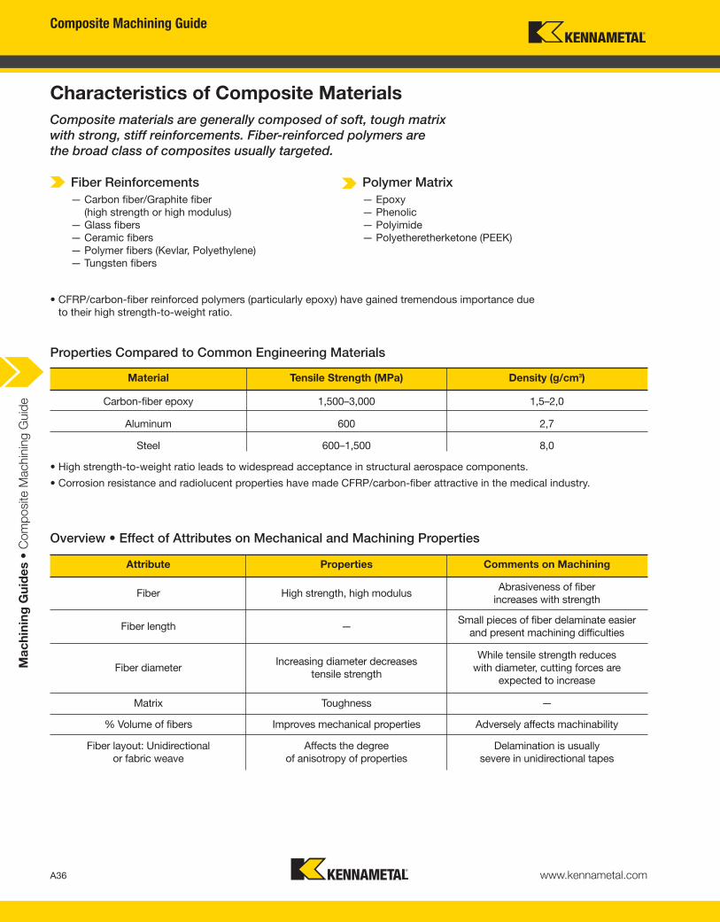
Characteristics of Composite Materials
Properties Compared to Common Engineering Materials
Overview • Effect of Attributes on Mechanical and Machining Properties
• High strength-to-weight ratio leads to widespread acceptance in structural aerospace components.
• Corrosion resistance and radiolucent properties have made CFRP/carbon-fiber attractive in the medical industry.
• CFRP/carbon-fiber reinforced polymers (particularly epoxy) have gained tremendous importance due
to their high strength-to-weight ratio.
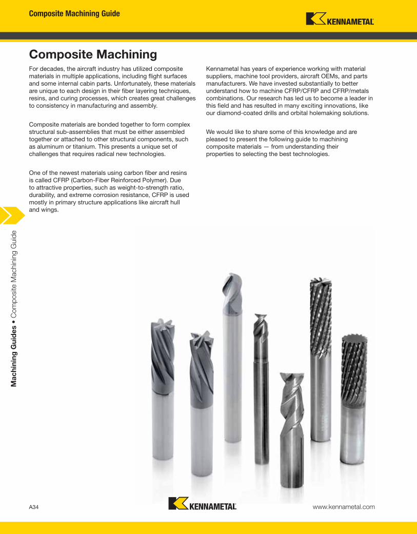
Composite materials are generally composed of soft, tough matrix
with strong, stiff reinforcements. Fiber-reinforced polymers are
the broad class of composites usually targeted.
Fiber Reinforcements
— Carbon fiber/Graphite fiber
(high strength or high modulus)
— Glass fibers
— Ceramic fibers
— Polymer fibers (Kevlar, Polyethylene)
— Tungsten fibers
Polymer Matrix
— Epoxy
— Phenolic
— Polyimide
— Polyetheretherketone (PEEK)
Material Tensile Strength (MPa) Density (g/cm3)
Carbon-fiber epoxy 1,500–3,000 1,5–2,0
Aluminum 600 2,7
Steel 600–1,500 8,0
Attribute Properties Comments on Machining
Fiber High strength, high modulusAbrasiveness of fiber
increases with strength
Fiber length —Small pieces of fiber delaminate easier
and present machining difficulties
Fiber diameterIncreasing diameter decreases
tensile strength
While tensile strength reduces
with diameter, cutting forces are
expected to increase
Matrix Toughness —
% Volume of fibers Improves mechanical properties Adversely affects machinability
Fiber layout: Unidirectional
or fabric weave
Affects the degree
of anisotropy of properties
Delamination is usually
severe in unidirectional tapes
Composite Machining Guide
A37www.kennametal.com
Ma
ch
inin
g G
uid
es •
Com
posite M
achin
ing G
uid
e
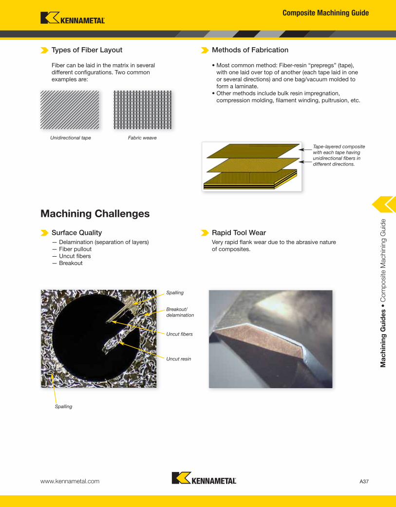
Types of Fiber Layout
Machining Challenges
Methods of Fabrication
Fiber can be laid in the matrix in several
different configurations. Two common
examples are:
Surface Quality
— Delamination (separation of layers)
— Fiber pullout
— Uncut fibers
— Breakout
Rapid Tool Wear
Very rapid flank wear due to the abrasive nature
of composites.
• Most common method: Fiber-resin “prepregs” (tape),
with one laid over top of another (each tape laid in one
or several directions) and one bag/vacuum molded to
form a laminate.
• Other methods include bulk resin impregnation,
compression molding, filament winding, pultrusion, etc.
Unidirectional tape Fabric weave
Tape-layered composite
with each tape having
unidirectional fibers in
different directions.
Spalling
Breakout/
delamination
Uncut fibers
Uncut resin
Spalling
Composite Machining Guide
A38 www.kennametal.com
Ma
ch
inin
g G
uid
es •
Com
posite M
achin
ing G
uid
e
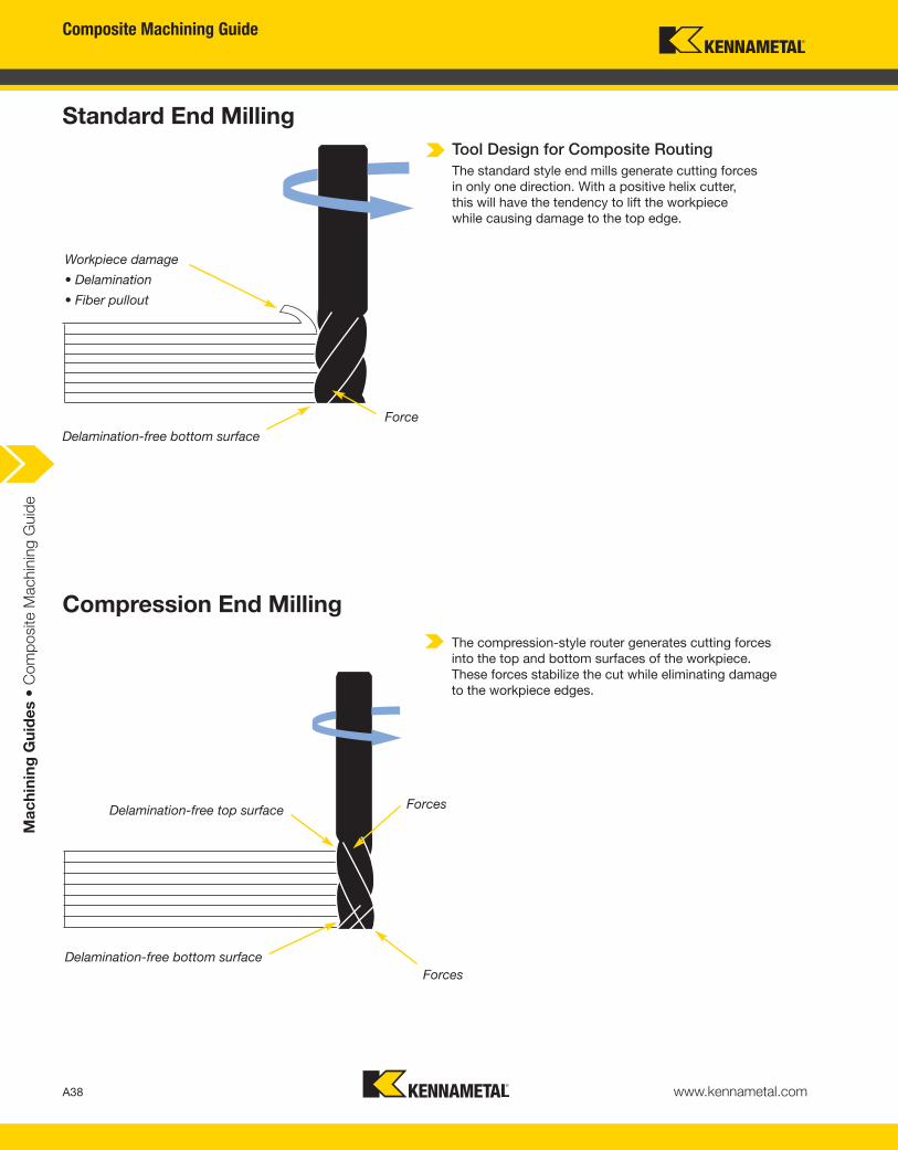
Standard End Milling
Compression End Milling
Tool Design for Composite Routing
The standard style end mills generate cutting forces
in only one direction. With a positive helix cutter,
this will have the tendency to lift the workpiece
while causing damage to the top edge.
The compression-style router generates cutting forces
into the top and bottom surfaces of the workpiece.
These forces stabilize the cut while eliminating damage
to the workpiece edges.
Delamination-free bottom surface
Workpiece damage
• Delamination
• Fiber pullout
Force
Forces
Forces
Delamination-free top surface
Delamination-free bottom surface

www.kennametal.com
• Aggressive ramping rates, high RPM capabilities, and a superior
surface finish — time after time.
• Varying axial depth of cut, meeting the challenges of a wide
range of applications.
• No material breakout or burr formation upon entry or exit
of the workpiece.
Ideal for applications utilizing Carbon-Fiber Reinforced Polymer (CFRP).
The Kennametal Mill 1-10 Indexable Milling Series —
Face Milling, up to 100% Engagement with PCD Inserts
Visit www.kennametal.com or contact your local Authorized Kennametal Distributor.
End or Face Milling Mill 1–10™
Choose the Mill 1-10 to mill 90˚ walls.
Composite Machining Guide
A40 www.kennametal.com
Ma
ch
inin
g G
uid
es •
Com
posite M
achin
ing G
uid
e
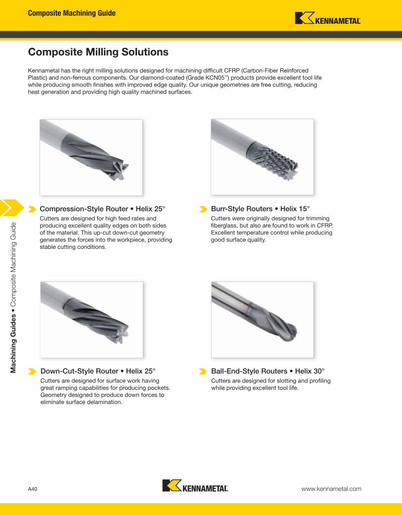
Composite Milling Solutions
Kennametal has the right milling solutions designed for machining difficult CFRP (Carbon-Fiber Reinforced
Plastic) and non-ferrous components. Our diamond-coated (Grade KCN05™) products provide excellent tool life
while producing smooth finishes with improved edge quality. Our unique geometries are free cutting, reducing
heat generation and providing high quality machined surfaces.
Compression-Style Router • Helix 25°
Cutters are designed for high feed rates and
producing excellent quality edges on both sides
of the material. This up-cut down-cut geometry
generates the forces into the workpiece, providing
stable cutting conditions.
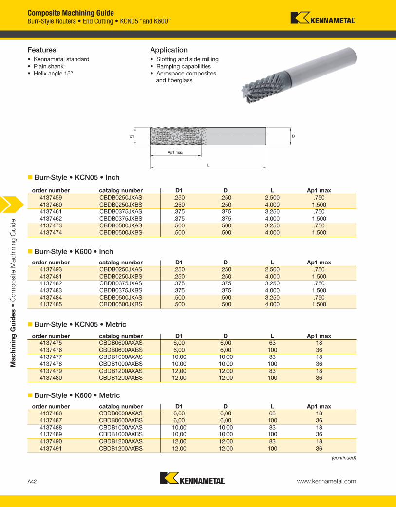
Burr-Style Routers • Helix 15°
Cutters were originally designed for trimming
fiberglass, but also are found to work in CFRP.
Excellent temperature control while producing
good surface quality.
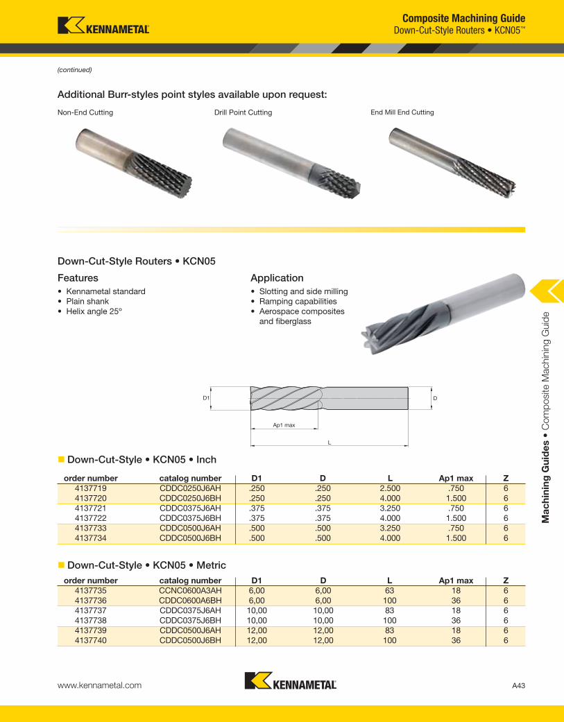
Down-Cut-Style Router • Helix 25°
Cutters are designed for surface work having
great ramping capabilities for producing pockets.
Geometry designed to produce down forces to
eliminate surface delamination.
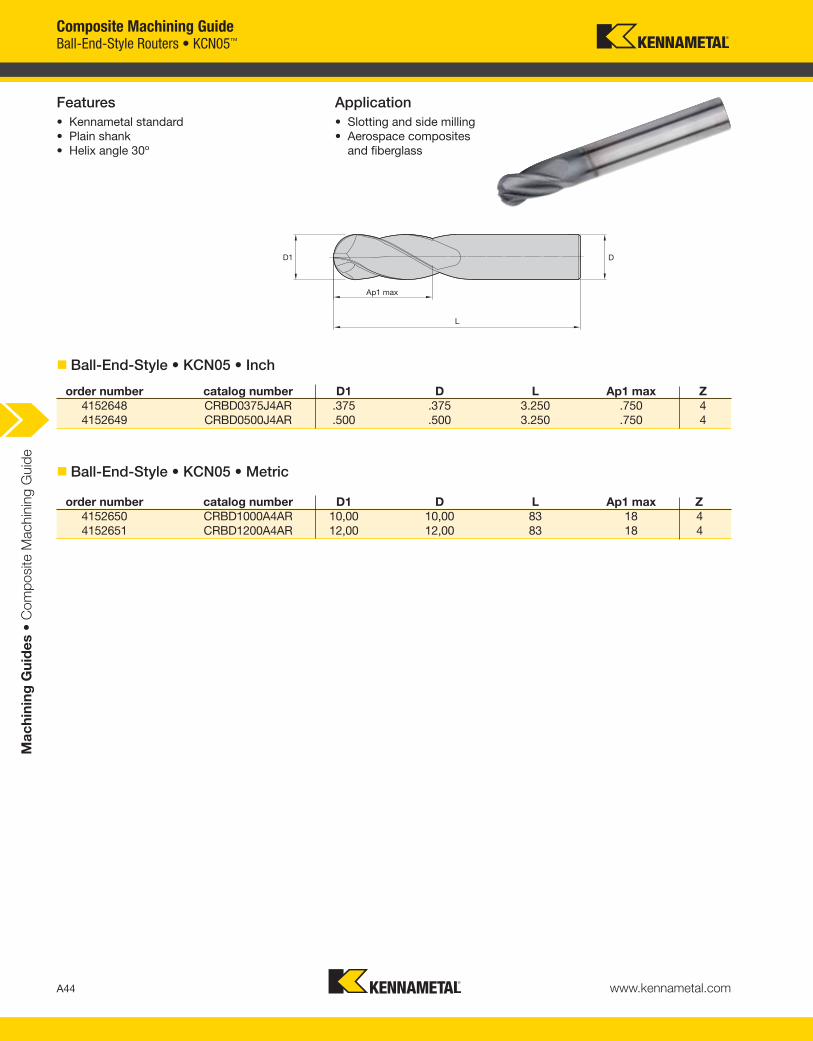
Ball-End-Style Routers • Helix 30°
Cutters are designed for slotting and profiling
while providing excellent tool life.
Composite Machining Guide
A41www.kennametal.com
Ma
ch
inin
g G
uid
es •
Com
posite M
achin
ing G
uid
e
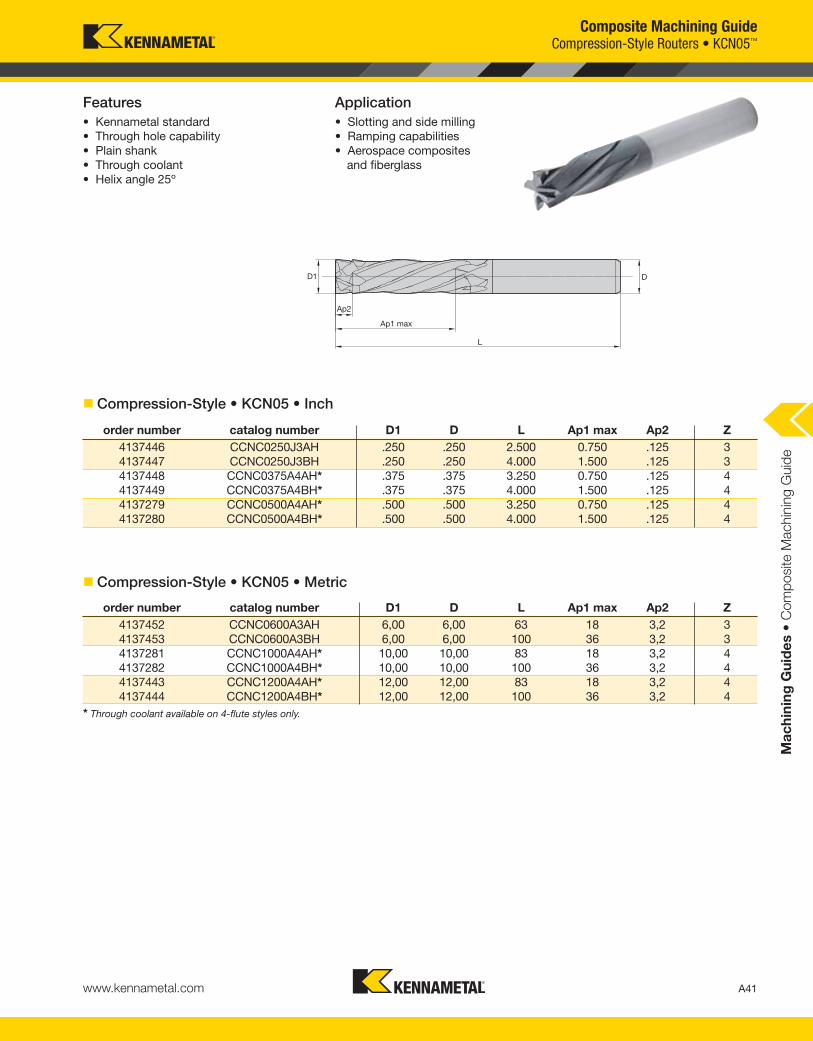
Features
• Kennametal standard
• Through hole capability
• Plain shank
• Through coolant
• Helix angle 25º
Application
• Slotting and side milling
• Ramping capabilities
• Aerospace composites
and fiberglass
order number catalog number D1 D L Ap1 max Ap2 Z
4137446 CCNC0250J3AH .250 .250 2.500 0.750 .125 3
4137447 CCNC0250J3BH .250 .250 4.000 1.500 .125 3
4137448 CCNC0375A4AH* .375 .375 3.250 0.750 .125 4
4137449 CCNC0375A4BH* .375 .375 4.000 1.500 .125 4
4137279 CCNC0500A4AH* .500 .500 3.250 0.750 .125 4
4137280 CCNC0500A4BH* .500 .500 4.000 1.500 .125 4
order number catalog number D1 D L Ap1 max Ap2 Z
4137452 CCNC0600A3AH 6,00 6,00 63 18 3,2 3
4137453 CCNC0600A3BH 6,00 6,00 100 36 3,2 3
4137281 CCNC1000A4AH* 10,00 10,00 83 18 3,2 4
4137282 CCNC1000A4BH* 10,00 10,00 100 36 3,2 4
4137443 CCNC1200A4AH* 12,00 12,00 83 18 3,2 4
4137444 CCNC1200A4BH* 12,00 12,00 100 36 3,2 4
Compression-Style Routers • KCN05™
� Compression-Style • KCN05 • Inch
� Compression-Style • KCN05 • Metric
* Through coolant available on 4-flute styles only.
Composite Machining Guide
A42 www.kennametal.com
Ma
ch
inin
g G
uid
es •
Com
posite M
achin
ing G
uid
e
Features
• Kennametal standard
• Plain shank
• Helix angle 15º
Application
• Slotting and side milling
• Ramping capabilities
• Aerospace composites
and fiberglass
order number catalog number D1 D L Ap1 max
4137459 CBDB0250JXAS .250 .250 2.500 .750
4137460 CBDB0250JXBS .250 .250 4.000 1.500
4137461 CBDB0375JXAS .375 .375 3.250 .750
4137462 CBDB0375JXBS .375 .375 4.000 1.500
4137473 CBDB0500JXAS .500 .500 3.250 .750
4137474 CBDB0500JXBS .500 .500 4.000 1.500
order number catalog number D1 D L Ap1 max
4137475 CBDB0600AXAS 6,00 6,00 63 18
4137476 CBDB0600AXBS 6,00 6,00 100 36
4137477 CBDB1000AXAS 10,00 10,00 83 18
4137478 CBDB1000AXBS 10,00 10,00 100 36
4137479 CBDB1200AXAS 12,00 12,00 83 18
4137480 CBDB1200AXBS 12,00 12,00 100 36
order number catalog number D1 D L Ap1 max
4137493 CBDB0250JXAS .250 .250 2.500 .750
4137481 CBDB0250JXBS .250 .250 4.000 1.500
4137482 CBDB0375JXAS .375 .375 3.250 .750
4137483 CBDB0375JXBS .375 .375 4.000 1.500
4137484 CBDB0500JXAS .500 .500 3.250 .750
4137485 CBDB0500JXBS .500 .500 4.000 1.500
order number catalog number D1 D L Ap1 max
4137486 CBDB0600AXAS 6,00 6,00 63 18
4137487 CBDB0600AXBS 6,00 6,00 100 36
4137488 CBDB1000AXAS 10,00 10,00 83 18
4137489 CBDB1000AXBS 10,00 10,00 100 36
4137490 CBDB1200AXAS 12,00 12,00 83 18
4137491 CBDB1200AXBS 12,00 12,00 100 36
Burr-Style Routers • End Cutting • KCN05™ and K600™
� Burr-Style • KCN05 • Inch
� Burr-Style • K600 • Inch
� Burr-Style • KCN05 • Metric
� Burr-Style • K600 • Metric
(continued)
Composite Machining Guide
A43www.kennametal.com
Ma
ch
inin
g G
uid
es •
Com
posite M
achin
ing G
uid
e
Features
• Kennametal standard
• Plain shank
• Helix angle 25º
Application
• Slotting and side milling
• Ramping capabilities
• Aerospace composites
and fiberglass
Additional Burr-styles point styles available upon request:
Non-End Cutting Drill Point Cutting End Mill End Cutting
order number catalog number D1 D L Ap1 max Z
4137719 CDDC0250J6AH .250 .250 2.500 .750 6
4137720 CDDC0250J6BH .250 .250 4.000 1.500 6
4137721 CDDC0375J6AH .375 .375 3.250 .750 6
4137722 CDDC0375J6BH .375 .375 4.000 1.500 6
4137733 CDDC0500J6AH .500 .500 3.250 .750 6
4137734 CDDC0500J6BH .500 .500 4.000 1.500 6
order number catalog number D1 D L Ap1 max Z
4137735 CCNC0600A3AH 6,00 6,00 63 18 6
4137736 CDDC0600A6BH 6,00 6,00 100 36 6
4137737 CDDC0375J6AH 10,00 10,00 83 18 6
4137738 CDDC0375J6BH 10,00 10,00 100 36 6
4137739 CDDC0500J6AH 12,00 12,00 83 18 6
4137740 CDDC0500J6BH 12,00 12,00 100 36 6
Down-Cut-Style Routers • KCN05™
� Down-Cut-Style • KCN05 • Inch
� Down-Cut-Style • KCN05 • Metric
(continued)
Down-Cut-Style Routers • KCN05
Composite Machining Guide
A44 www.kennametal.com
Ma
ch
inin
g G
uid
es •
Com
posite M
achin
ing G
uid
e
Features
• Kennametal standard
• Plain shank
• Helix angle 30º
Application
• Slotting and side milling
• Aerospace composites
and fiberglass
order number catalog number D1 D L Ap1 max Z
4152648 CRBD0375J4AR .375 .375 3.250 .750 4
4152649 CRBD0500J4AR .500 .500 3.250 .750 4
order number catalog number D1 D L Ap1 max Z
4152650 CRBD1000A4AR 10,00 10,00 83 18 4
4152651 CRBD1200A4AR 12,00 12,00 83 18 4
� Ball-End-Style • KCN05 • Inch
� Ball-End-Style • KCN05 • Metric
Ball-End-Style Routers • KCN05™
Composite Machining Guide
A45www.kennametal.com
Ma
ch
inin
g G
uid
es •
Com
posite M
achin
ing G
uid
e
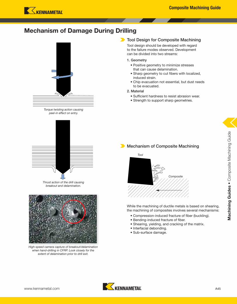
Mechanism of Damage During Drilling
Mechanism of Composite Machining
Tool Design for Composite Machining
Tool design should be developed with regard
to the failure modes observed. Development
can be divided into two streams:
1. Geometry
• Positive geometry to minimize stresses
that can cause delamination.
• Sharp geometry to cut fibers with localized,
induced strain.
• Chip evacuation not essential, but dust needs
to be evacuated.
2. Material
• Sufficient hardness to resist abrasion wear.
• Strength to support sharp geometries.
While the machining of ductile metals is based on shearing,
the machining of composites involves several mechanisms:
• Compression-induced fracture of fiber (buckling).
• Bending-induced fracture of fiber.
• Shearing, yielding, and cracking of the matrix.
• Interfacial debonding.
• Sub-surface damage.
Torque twisting action causing
peel-in effect on entry.
Thrust action of the drill causing
breakout and delamination.
Tool
Composite
High-speed camera capture of breakout/delamination
when hand-drilling in CFRP. Look closely for the
extent of delamination prior to drill exit.
71.17/16
66.72/15
62.28/14
57.83/13
53.38/12
48.93/11
44.48/10
2 7 12 17 22 27 32 37 42 47 52 57 62 67 72 77 82 87 92 97 102 107
3,05/0.12"
2,54/0.1"
2,03/0.08"
1,52/0.06"
1,02/0.04"
0,51/0.02"
0
Drill Configuration Parameters Hole Quality Criteria Incorrect Drill ConfigurationKMT SPF Drill Configured
Specifically for CFRP
Helix angle, clearance gash, rakeFiber pull out,
delamination, uncut fibers
Composite Machining Guide
A46 www.kennametal.com
Ma
ch
inin
g G
uid
es •
Com
posite M
achin
ing G
uid
e
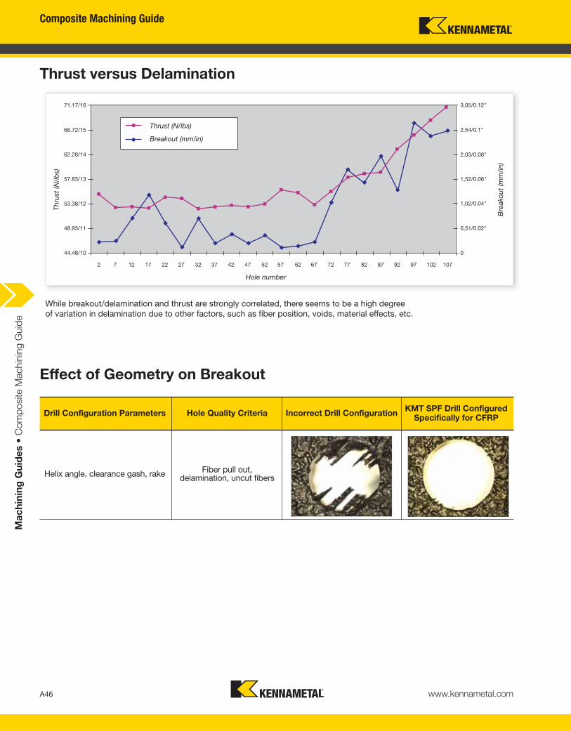
Thrust versus Delamination
Effect of Geometry on Breakout
Thru
st
(N/lb
s)
Bre
ako
ut
(mm
/in)
Thrust (N/lbs)
Breakout (mm/in)
Hole number
While breakout/delamination and thrust are strongly correlated, there seems to be a high degree
of variation in delamination due to other factors, such as fiber position, voids, material effects, etc.
A47www.kennametal.com
Ma
ch
inin
g G
uid
es •
Com
posite M
achin
ing G
uid
e
Composite Machining Guide
Hole #1 Hole #30 Hole #60 Hole #150 Hole #300
PC
DK
en
na
me
tal
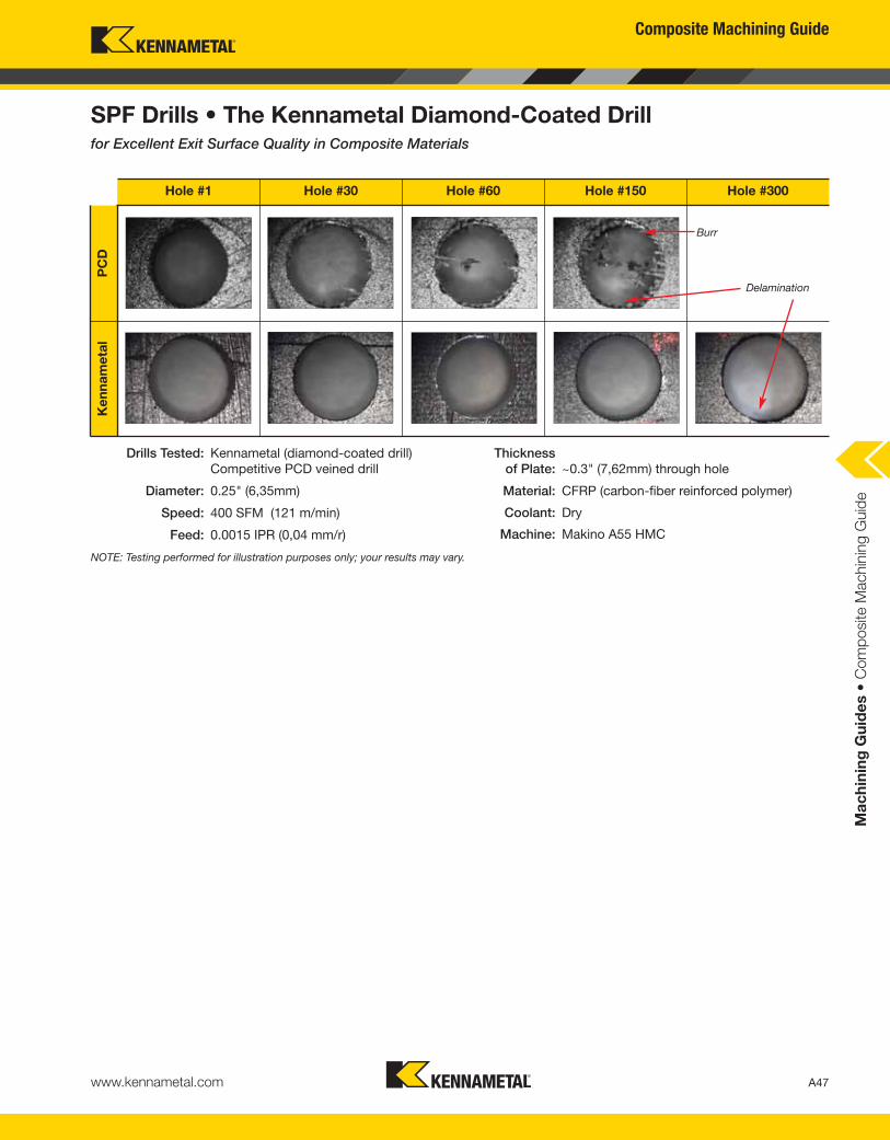
SPF Drills • The Kennametal Diamond-Coated Drillfor Excellent Exit Surface Quality in Composite Materials
NOTE: Testing performed for illustration purposes only; your results may vary.
Delamination
Burr
Drills Tested: Kennametal (diamond-coated drill)
Competitive PCD veined drill
Diameter: 0.25" (6,35mm)
Speed: 400 SFM (121 m/min)
Feed: 0.0015 IPR (0,04 mm/r)
Thickness
of Plate: ~0.3" (7,62mm) through hole
Material: CFRP (carbon-fiber reinforced polymer)
Coolant: Dry
Machine: Makino A55 HMC
Composite Machining Guide
A48 www.kennametal.com
Ma
ch
inin
g G
uid
es •
Com
posite M
achin
ing G
uid
e
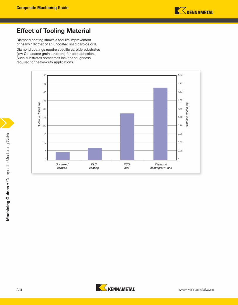
Effect of Tooling Material
1.97"
1.77"
1.57"
1.37"
1.18"
0.98"
0.79"
0.59"
0.39"
0.20"
0
50
45
40
35
30
25
20
15
10
5
0
Dis
tance d
rille
d (m
)
Uncoated
carbide
DLC
coating
PCD
drill
Diamond
coating/SPF drill
Diamond coating shows a tool life improvement
of nearly 10x that of an uncoated solid carbide drill.
Diamond coatings require specific carbide substrates
(low Co, coarse grain structure) for best adhesion.
Such substrates sometimes lack the toughness
required for heavy-duty applications.
Dis
tance d
rille
d (in
)
A49www.kennametal.com
Ma
ch
inin
g G
uid
es •
Com
posite M
achin
ing G
uid
e
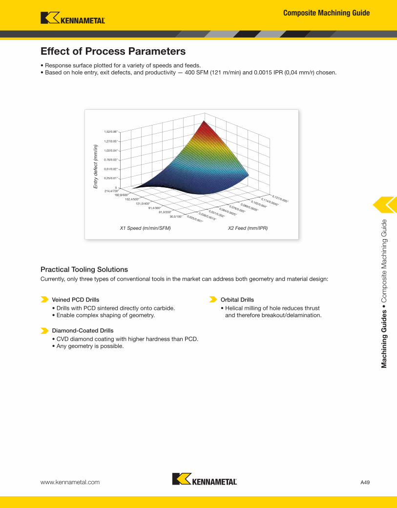
Effect of Process Parameters
Practical Tooling Solutions
Currently, only three types of conventional tools in the market can address both geometry and material design:
• Response surface plotted for a variety of speeds and feeds.
• Based on hole entry, exit defects, and productivity — 400 SFM (121 m/min) and 0.0015 IPR (0,04 mm/r) chosen.
Veined PCD Drills
• Drills with PCD sintered directly onto carbide.
• Enable complex shaping of geometry.
Diamond-Coated Drills
• CVD diamond coating with higher hardness than PCD.
• Any geometry is possible.
Orbital Drills
• Helical milling of hole reduces thrust
and therefore breakout/delamination.
1,52/0.06"
1,27/0.05"
1,02/0.04"
0.76/0.03"
0,51/0.02"
0,25/0.01"
214,4/700"182,8/600"
152,4/500"
121,0/400"
91,4/300"61,0/200"
30,5/100" 0,025/0.001"
0,038/0.0015"
0,051/0.002"
0,064/0.0025"
0,076/0.003"
0,089/0.0035"
0,102/0.004"
0,127/0.005"0,114/0.0045"
X1 Speed (m/min/SFM) X2 Feed (mm/IPR)
Entr
y d
efe
ct
(mm
/in)
Composite Machining Guide
Composite Machining Guide
A50 www.kennametal.com
Ma
ch
inin
g G
uid
es •
Com
posite M
achin
ing G
uid
e
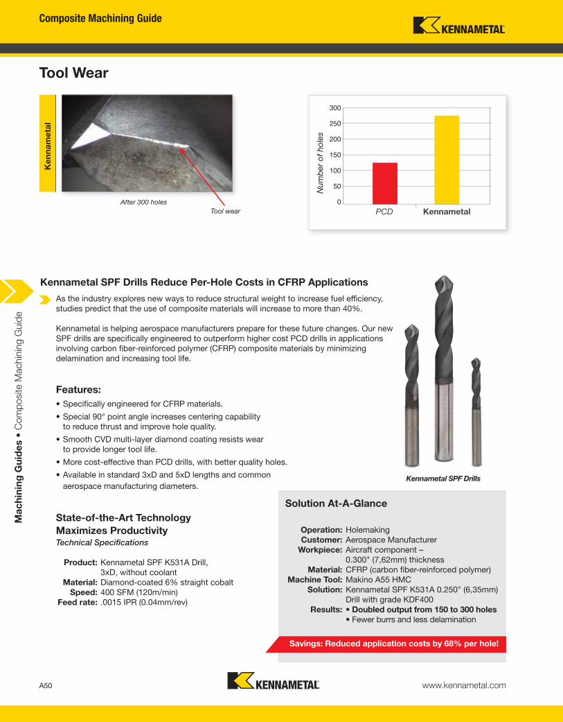
Tool Wear
After 300 holes
Tool wear
Ke
nn
am
eta
l
300
250
200
150
100
50
0PCD Kennametal
Num
ber
of
ho
les
As the industry explores new ways to reduce structural weight to increase fuel efficiency,
studies predict that the use of composite materials will increase to more than 40%.
Kennametal is helping aerospace manufacturers prepare for these future changes. Our new
SPF drills are specifically engineered to outperform higher cost PCD drills in applications
involving carbon fiber-reinforced polymer (CFRP) composite materials by minimizing
delamination and increasing tool life.
Kennametal SPF Drills Reduce Per-Hole Costs in CFRP Applications
State-of-the-Art Technology
Maximizes ProductivityTechnical Specifications
Product: Kennametal SPF K531A Drill,
3xD, without coolant
Material: Diamond-coated 6% straight cobalt
Speed: 400 SFM (120m/min)
Feed rate: .0015 IPR (0.04mm/rev)
Savings: Reduced application costs by 68% per hole!
Solution At-A-Glance
Operation: Holemaking
Customer: Aerospace Manufacturer
Workpiece: Aircraft component –
0.300" (7,62mm) thickness
Material: CFRP (carbon fiber-reinforced polymer)
Machine Tool: Makino A55 HMC
Solution: Kennametal SPF K531A 0.250" (6,35mm)
Drill with grade KDF400
Results: • Doubled output from 150 to 300 holes
• Fewer burrs and less delamination
Features:
• Specifically engineered for CFRP materials.
• Special 90° point angle increases centering capability
to reduce thrust and improve hole quality.
• Smooth CVD multi-layer diamond coating resists wear
to provide longer tool life.
• More cost-effective than PCD drills, with better quality holes.
• Available in standard 3xD and 5xD lengths and common
aerospace manufacturing diameters.Kennametal SPF Drills
Composite Machining Guide
A51www.kennametal.com
Ma
ch
inin
g G
uid
es •
Com
posite M
achin
ing G
uid
e
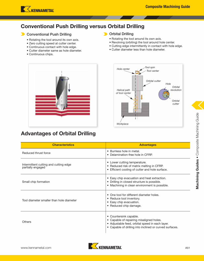
Conventional Push Drilling versus Orbital Drilling
Advantages of Orbital Drilling
Conventional Push Drilling
• Rotating the tool around its own axis.
• Zero cutting speed at cutter center.
• Continuous contact with hole edge.
• Cutter diameter same as hole diameter.
• Continuous chips.
Orbital Drilling
• Rotating the tool around its own axis.
• Revolving (orbiting) the tool around hole center.
• Cutting edge intermittently in contact with hole edge.
• Cutter diameter less than hole diameter.
Hole centerTool spin
Tool center
Orbital cutter
Helical path
of tool center
Workpiece
Orbital
cutter
Hole
Orbital
revolution
Characteristics Advantages
Reduced thrust force• Burrless hole in metal.
• Delamination-free hole in CFRP.
Intermittent cutting and cutting edge partially engaged
• Lower cutting temperature.
• Reduced risk of matrix melting in CFRP.
• Efficient cooling of cutter and hole surface.
Small chip formation
• Easy chip evacuation and heat extraction.
• Drilling in closed structure is possible.
• Machining in clean environment is possible.
Tool diameter smaller than hole diameter
• One tool for different diameter holes.
• Reduce tool inventory.
• Easy chip evacuation.
• Reduced chip damage.
Others
• Countersink capable.
• Capable of repairing misaligned holes.
• Adjustable feed, orbital speed in each layer.
• Capable of drilling into inclined or curved surfaces.
Composite Machining Guide
A52 www.kennametal.com
Ma
ch
inin
g G
uid
es •
Com
posite M
achin
ing G
uid
e
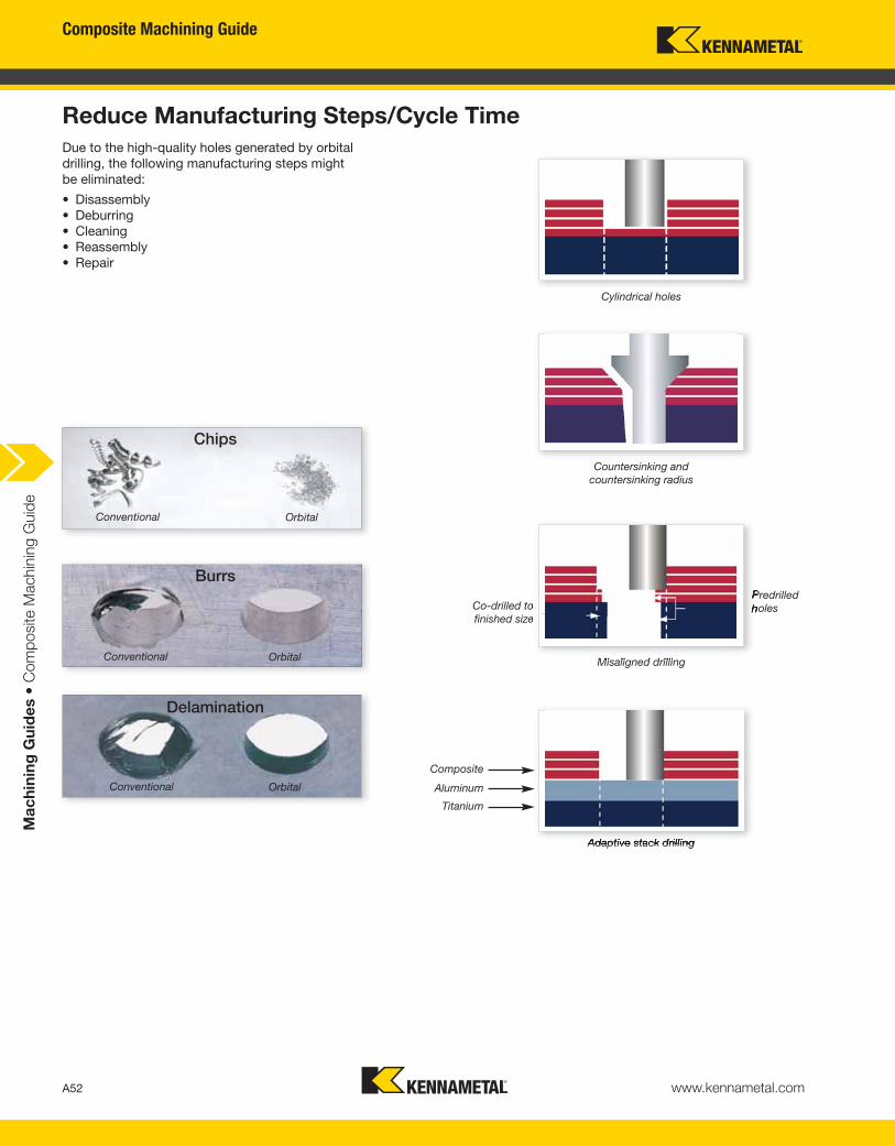
Reduce Manufacturing Steps/Cycle Time
Due to the high-quality holes generated by orbital
drilling, the following manufacturing steps might
be eliminated:
• Disassembly
• Deburring
• Cleaning
• Reassembly
• Repair
Chips
Conventional Orbital
Burrs
Conventional Orbital
Delamination
Conventional Orbital
Cylindrical holes
Countersinking and
countersinking radius
Misaligned drilling
Adaptive stack drilling
Predrilled
holesCo-drilled to
finished size
Composite
Aluminum
Titanium
Composite Machining Guide
A53www.kennametal.com
Ma
ch
inin
g G
uid
es •
Com
posite M
achin
ing G
uid
e
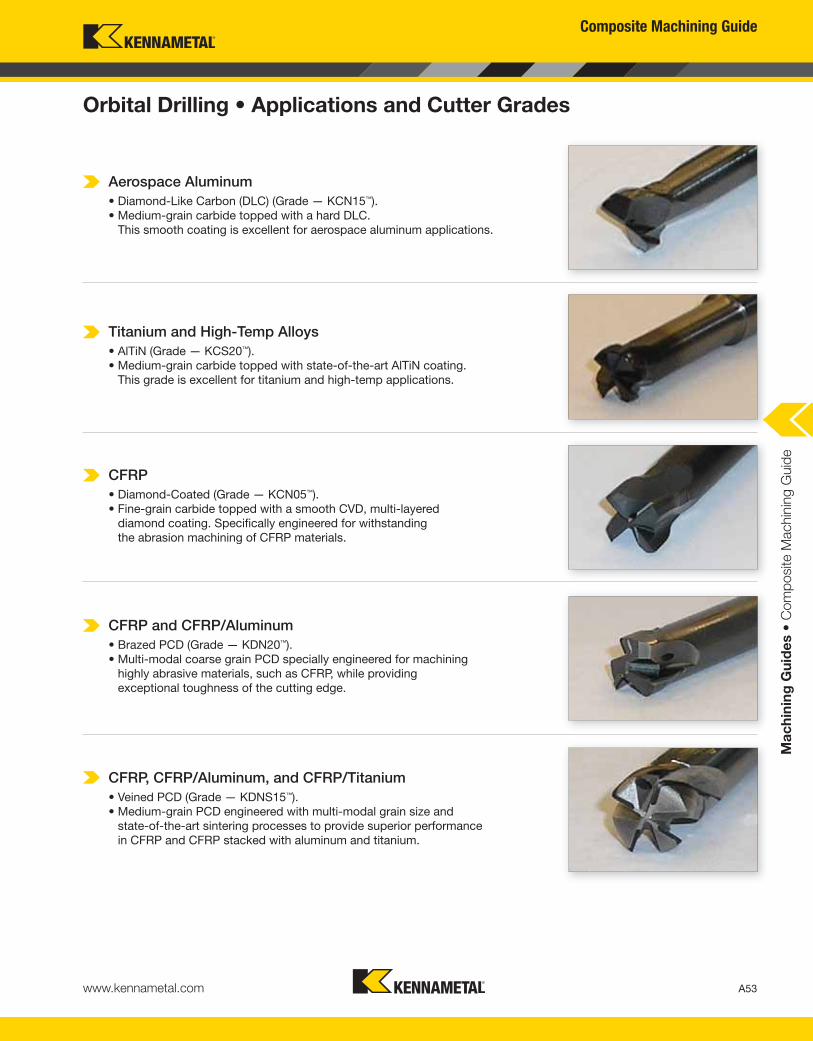
Orbital Drilling • Applications and Cutter Grades
Aerospace Aluminum
• Diamond-Like Carbon (DLC) (Grade — KCN15™).
• Medium-grain carbide topped with a hard DLC.
This smooth coating is excellent for aerospace aluminum applications.
Titanium and High-Temp Alloys
• AlTiN (Grade — KCS20™).
• Medium-grain carbide topped with state-of-the-art AlTiN coating.
This grade is excellent for titanium and high-temp applications.
CFRP
• Diamond-Coated (Grade — KCN05™).
• Fine-grain carbide topped with a smooth CVD, multi-layered
diamond coating. Specifically engineered for withstanding
the abrasion machining of CFRP materials.
CFRP and CFRP/Aluminum
• Brazed PCD (Grade — KDN20™).
• Multi-modal coarse grain PCD specially engineered for machining
highly abrasive materials, such as CFRP, while providing
exceptional toughness of the cutting edge.
CFRP, CFRP/Aluminum, and CFRP/Titanium
• Veined PCD (Grade — KDNS15™).
• Medium-grain PCD engineered with multi-modal grain size and
state-of-the-art sintering processes to provide superior performance
in CFRP and CFRP stacked with aluminum and titanium.
Composite Machining Guide
A54 www.kennametal.com
Ma
ch
inin
g G
uid
es •
Com
posite M
achin
ing G
uid
e
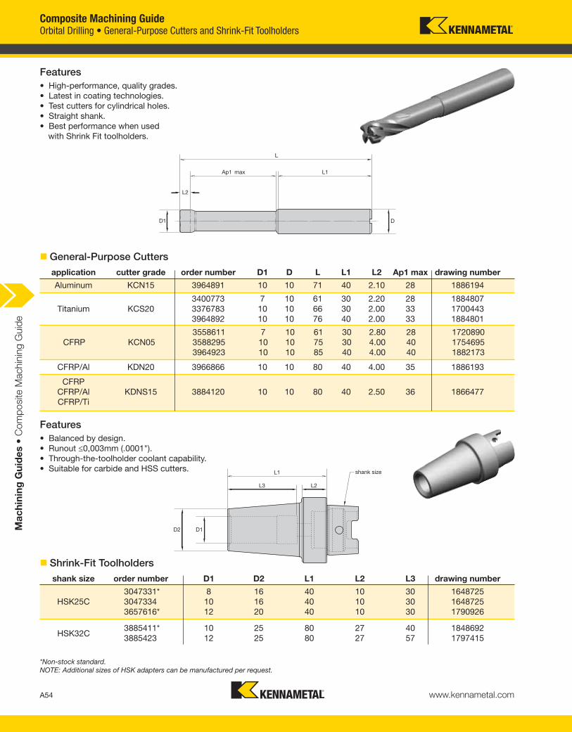
� General-Purpose Cutters
Features
• High-performance, quality grades.
• Latest in coating technologies.
• Test cutters for cylindrical holes.
• Straight shank.
• Best performance when used
with Shrink Fit toolholders.
Features
• Balanced by design.
• Runout ≤0,003mm (.0001").
• Through-the-toolholder coolant capability.
• Suitable for carbide and HSS cutters.
*Non-stock standard.
NOTE: Additional sizes of HSK adapters can be manufactured per request.
application cutter grade order number D1 D L L1 L2 Ap1 max drawing number
Aluminum KCN15 3964891 10 10 71 40 2.10 28 1886194
3400773 7 10 61 30 2.20 28 1884807
Titanium KCS20 3376783 10 10 66 30 2.00 33 1700443
3964892 10 10 76 40 2.00 33 1884801
3558611 7 10 61 30 2.80 28 1720890
CFRP KCN05 3588295 10 10 75 30 4.00 40 1754695
3964923 10 10 85 40 4.00 40 1882173
CFRP
CFRP/Al KDNS15 3884120 10 10 80 40 2.50 36 1866477
CFRP/Ti
CFRP/Al KDN20 3966866 10 10 80 40 4.00 35 1886193
shank size order number D1 D2 L1 L2 L3 drawing number
3047331* 8 16 40 10 30 1648725
HSK25C 3047334 10 16 40 10 30 1648725
3657616* 12 20 40 10 30 1790926
3885411* 10 25 80 27 40 1848692
3885423 12 25 80 27 57 1797415HSK32C
� Shrink-Fit Toolholders
Orbital Drilling • General-Purpose Cutters and Shrink-Fit Toolholders
Composite Machining Guide
A55www.kennametal.com
Ma
ch
inin
g G
uid
es •
Com
posite M
achin
ing G
uid
e
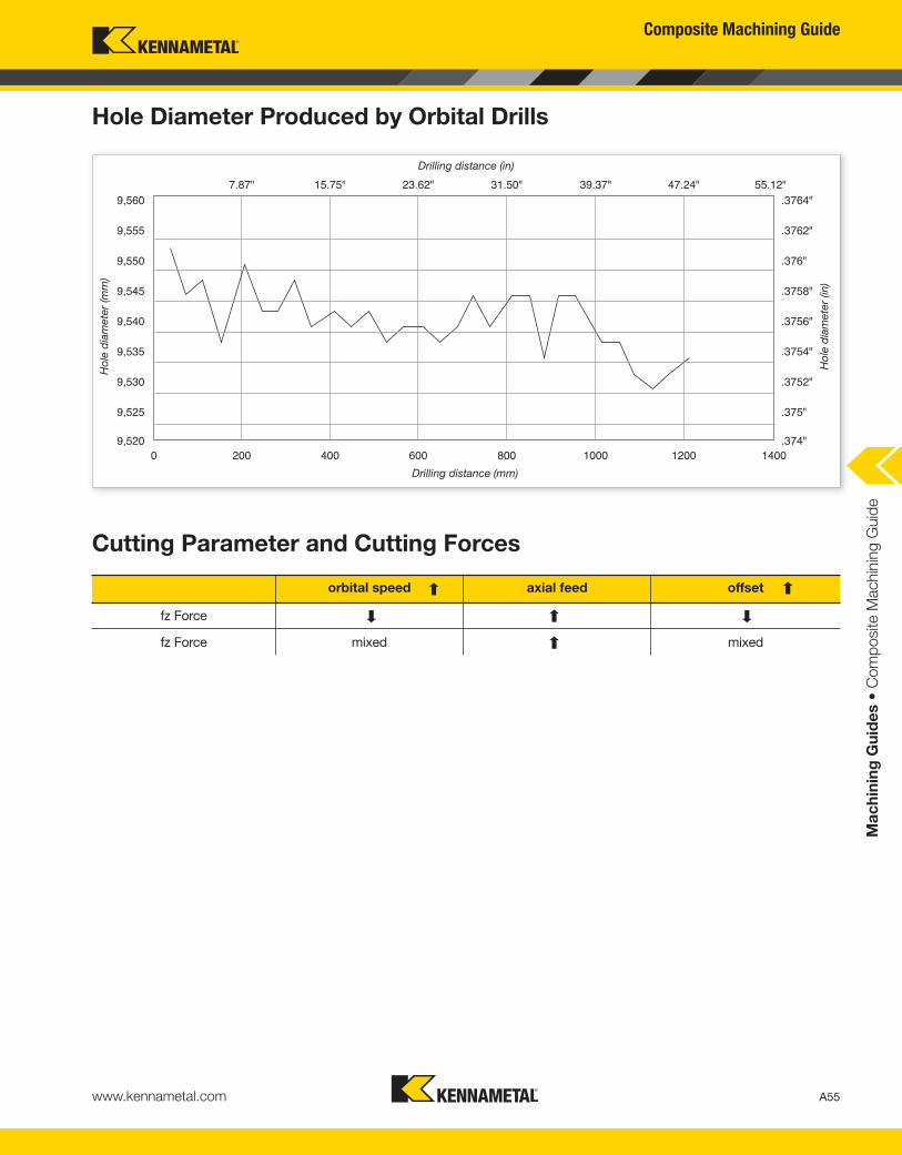
Hole Diameter Produced by Orbital Drills
9,560
9,555
9,550
9,545
9,540
9,535
9,530
9,525
9,5200 200 400 600 800 1000 1200 1400
Drilling distance (mm)
Ho
le d
iam
ete
r (m
m)
Cutting Parameter and Cutting Forces
orbital speed axial feed offset
fz Force
fz Force mixed mixed
.3764"
.3762"
.376"
.3758"
.3756"
.3754"
.3752"
.375"
.374"
7.87" 15.75" 23.62" 31.50" 39.37" 47.24" 55.12"Drilling distance (in)
Ho
le d
iam
ete
r (in)