Embed Size (px)
Citation preview
Master Thesis Master Degree program in Robotics Department of Engineering Science
May 26, 2010
Robotized Polishing and Deburring
with Force Feedback Control
Marthin Krantz Rikard Andersson
i
Robotized Polishing and Deburring with Force Feedback Control
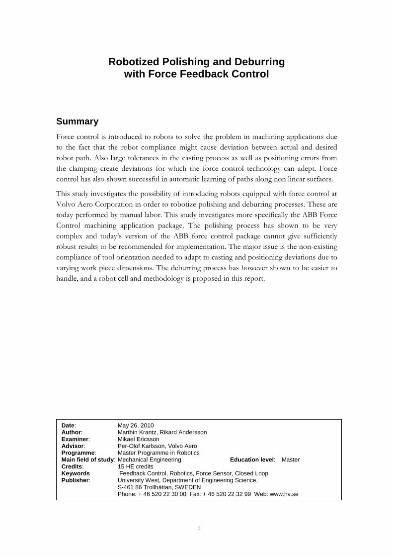
Summary
Force control is introduced to robots to solve the problem in machining applications due
to the fact that the robot compliance might cause deviation between actual and desired
robot path. Also large tolerances in the casting process as well as positioning errors from
the clamping create deviations for which the force control technology can adept. Force
control has also shown successful in automatic learning of paths along non linear surfaces.
This study investigates the possibility of introducing robots equipped with force control at
Volvo Aero Corporation in order to robotize polishing and deburring processes. These are
today performed by manual labor. This study investigates more specifically the ABB Force
Control machining application package. The polishing process has shown to be very
complex and today’s version of the ABB force control package cannot give sufficiently
robust results to be recommended for implementation. The major issue is the non-existing
compliance of tool orientation needed to adapt to casting and positioning deviations due to
varying work piece dimensions. The deburring process has however shown to be easier to
handle, and a robot cell and methodology is proposed in this report.
Date: May 26, 2010 Author: Marthin Krantz, Rikard Andersson Examiner: Mikael Ericsson Advisor: Per-Olof Karlsson, Volvo Aero Programme: Master Programme in Robotics Main field of study: Mechanical Engineering Education level: Master Credits: 15 HE credits Keywords Feedback Control, Robotics, Force Sensor, Closed Loop Publisher: University West, Department of Engineering Science,
S-461 86 Trollhättan, SWEDEN Phone: + 46 520 22 30 00 Fax: + 46 520 22 32 99 Web: www.hv.se

ii
Acknowledgements
We would like to thank everyone who helped us this study, especially Per-Olof Karlsson
who has supported us with material, knowledge and encouragement. We also want to thank
Anna-Karin Christiansson for her assistance throughout the project. Mark Daisley(RDS
Robotics), Hannu Rajala(RDS Robotics), Jonny Antonsson(AzonRobotix) and Jörgen
Magnusson(VAC) have all contributed with their extensive experience in robotics.
iii
Contents
Summary .............................................................................................................................................. i
Acknowledgements ........................................................................................................................... ii
Symbols and glossary ........................................................................................................................ v
1 Introduction ................................................................................................................................ 1 1.1 Task .................................................................................................................................... 1 1.2 Goal .................................................................................................................................... 1 1.3 Limitations ........................................................................................................................ 2
2 Related research .......................................................................................................................... 3 2.1 Oxide removal with force control robot ...................................................................... 3 2.2 Force control .................................................................................................................... 3
2.2.1 Control strategies ................................................................................................ 4 2.2.2 Bandwidth and stability ..................................................................................... 5 2.2.3 Low frequency chatter ....................................................................................... 5
2.3 Robotized polishing ......................................................................................................... 6 2.3.1 Polishing tools .................................................................................................... 6 2.3.2 Path planning ...................................................................................................... 7
2.4 Casting oxides ................................................................................................................... 8 2.5 Components ..................................................................................................................... 9 2.6 Robotized Deburring ..................................................................................................... 10
3 Experimental robot system setup .......................................................................................... 12 3.1 Spindle ............................................................................................................................. 12 3.2 Force/Torque Sensor .................................................................................................... 13
4 Robot programming, force control ....................................................................................... 14 4.1 On-line programming .................................................................................................... 14 4.2 Off-line programming ................................................................................................... 15
5 Data collection/measurements .............................................................................................. 18 5.1 Force sensor system ....................................................................................................... 18 5.2 Logging of Forces .......................................................................................................... 19 5.3 Logging of Spindle motor current ............................................................................... 19 5.4 Coordinate-measuring machine ................................................................................... 19
6 Results ........................................................................................................................................ 21 6.1 FC Pressure ..................................................................................................................... 21
6.1.1 Positioning errors ............................................................................................. 21 6.1.2 Analysis of low frequency chatter during force control ............................. 22 6.1.3 Control Loop Parameters ............................................................................... 25 6.1.4 Polishing with flap wheel ................................................................................ 28 6.1.5 Polishing with rotating carbide tool .............................................................. 29
6.2 FC SpeedChange for deburring ................................................................................... 31 6.2.1 Deburring with modified tool ........................................................................ 31 6.2.2 Automatic learning ........................................................................................... 31
7 Cell for deburring of total assembly of TEC ....................................................................... 32
8 Conclusions and future work ................................................................................................. 34
References ........................................................................................................................................ 35

iv
Appendices
A. ABB IRB 4400/45
B. Force/Torque Sensor
C. PMC330 DAQ card
D. Spindle Specification
E. FC SpeedChange RAPID code example
F. FC Pressure RAPID code example
v
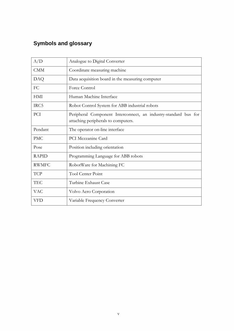
Symbols and glossary
A/D Analogue to Digital Converter
CMM Coordinate measuring machine
DAQ Data acquisition board in the measuring computer
FC Force Control
HMI Human Machine Interface
IRC5 Robot Control System for ABB industrial robots
PCI Peripheral Component Interconnect, an industry-standard bus for
attaching peripherals to computers.
Pendant The operator on-line interface
PMC PCI Mezzanine Card
Pose Position including orientation
RAPID Programming Language for ABB robots
RWMFC RobotWare for Machining FC
TCP Tool Center Point
TEC Turbine Exhaust Case
VAC Volvo Aero Corporation
VFD Variable Frequency Converter

1
1 Introduction
A large proportion of the hours spent on the components produced at Volvo Aero are
done by manual labor. In order to reduce these hours two processes are identified for
which automated robot cell solutions will be proposed.
Today before welding of sub components to complete weld assemblies, a manual polishing
is done. The purpose is to remove oxides which can exist in the surface of these
components. By use of force control a constant polishing pressure can be applied to the
work piece as well as adaptation for deviation between programmed and actual path along
the work piece.
During the milling process of casted components burrs are generated. Since the casting
process gives large tolerances, robotized deburring is impossible without a system to adapt
to these position errors.
Machining is a demanding task for a robot. Lack of stiffness in the robot structure, tool
wear, tolerances of parts and fixtures will introduce position errors that will give
inconsistent process results. Introducing force feedback opens the possibility to reduce
these position errors. Today the major European industrial robot providers like Stäubli,
Kuka, and ABB offer some possibility of utilizing force control.
1.1 Task
The purpose of this study is to examine and demonstrate robotized solutions for polishing
and deburring on aero engine structural components. The work is performed together and
with help of a team consisting of members from Volvo Aero Corporation (VAC), Azon
Robotix, RDS and University West. ABB is supplying a robot cell for evaluating the force
control for polishing. The study is including:
- A literature study of relevant research of weld preparation, robots with force
control, polishing, deburring and machining with robot.
- Simulations in RobotStudio [1] in order to evaluate ABB’s machining power pack
for off-line programming.
- Test runs for evaluation of a robot utilized with force control for deburring and
polishing applications.
1.2 Goal
The goal of the study is to:
Present relevant research done in the field of robotic force control, polishing and
deburring.

2
Evaluate RobotStudio with the machining power pack as an off-line programming tool.
Generate paths for polishing of a work piece represented by a CAD model. Investigate
reachability for a robot in a deburring cell for the total assembly of the TEC (Turbine
Exhaust Case).
Perform test runs of polishing and deburring on test pieces with the robot cell, to evaluate
advantages and limitations of the force control technology.
1.3 Limitations
This master thesis study includes tests performed in a pre-determined robot cell supplied
by ABB (Västerås, Sweden). The test includes evaluation of tools and path following
abilities. In this study results of the test runs and simulations in RobotStudio are presented.
The work does not include selection of robot, design of electrical, control and safety
system.
3
2 Related research
Research in this field has been active the last 30 years, but industrialized robotic systems
with user friendly interfaces have only been a reality the last couple of years. The
department of Automatic Control in Lund University has published a series of articles,
which is the foundation of the force control system available for a range of ABB robots
and also utilized in this project. Their work is well summarized and demonstrated in [2].
2.1 Oxide removal with force control robot
Removing oxides is done by polishing. The task of polishing with a force control robot can
be divided into three sub problems:
The polishing process, choice of tool(s), feed rates, rotation speed of tool. Force against
surface/environment.
Force Control Loop, bandwidth of control loop, feedback from sensor.
Path generation and following.
These three sub problems do affect each other and these affects need to be considered
during design, programming and configuration of the system.
2.2 Force control
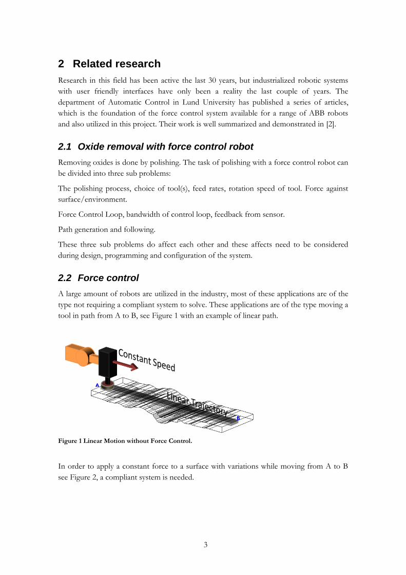
A large amount of robots are utilized in the industry, most of these applications are of the
type not requiring a compliant system to solve. These applications are of the type moving a
tool in path from A to B, see Figure 1 with an example of linear path.
Figure 1 Linear Motion without Force Control.
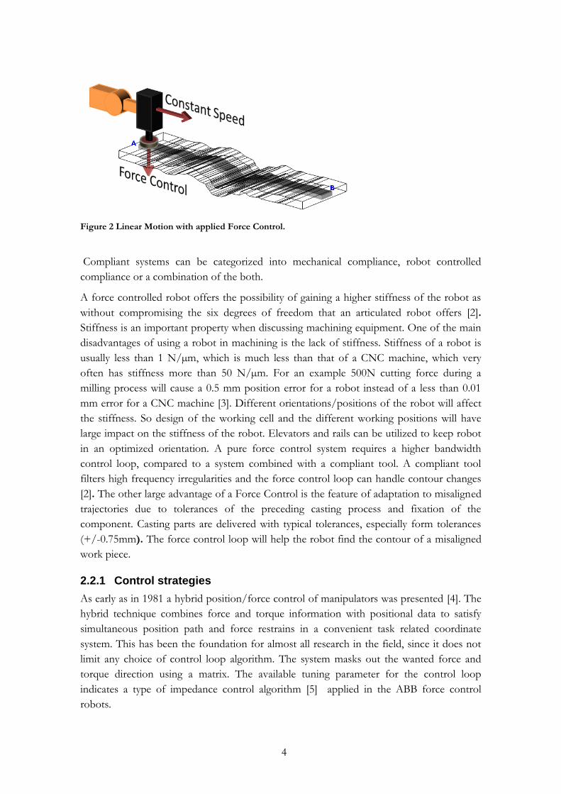
In order to apply a constant force to a surface with variations while moving from A to B
see Figure 2, a compliant system is needed.
4
Figure 2 Linear Motion with applied Force Control.
Compliant systems can be categorized into mechanical compliance, robot controlled
compliance or a combination of the both.
A force controlled robot offers the possibility of gaining a higher stiffness of the robot as
without compromising the six degrees of freedom that an articulated robot offers [2].
Stiffness is an important property when discussing machining equipment. One of the main
disadvantages of using a robot in machining is the lack of stiffness. Stiffness of a robot is
usually less than 1 N/µm, which is much less than that of a CNC machine, which very
often has stiffness more than 50 N/µm. For an example 500N cutting force during a
milling process will cause a 0.5 mm position error for a robot instead of a less than 0.01
mm error for a CNC machine [3]. Different orientations/positions of the robot will affect
the stiffness. So design of the working cell and the different working positions will have
large impact on the stiffness of the robot. Elevators and rails can be utilized to keep robot
in an optimized orientation. A pure force control system requires a higher bandwidth
control loop, compared to a system combined with a compliant tool. A compliant tool
filters high frequency irregularities and the force control loop can handle contour changes
[2]. The other large advantage of a Force Control is the feature of adaptation to misaligned
trajectories due to tolerances of the preceding casting process and fixation of the
component. Casting parts are delivered with typical tolerances, especially form tolerances
(+/-0.75mm). The force control loop will help the robot find the contour of a misaligned
work piece.
2.2.1 Control strategies
As early as in 1981 a hybrid position/force control of manipulators was presented [4]. The
hybrid technique combines force and torque information with positional data to satisfy
simultaneous position path and force restrains in a convenient task related coordinate
system. This has been the foundation for almost all research in the field, since it does not
limit any choice of control loop algorithm. The system masks out the wanted force and
torque direction using a matrix. The available tuning parameter for the control loop
indicates a type of impedance control algorithm [5] applied in the ABB force control
robots.

5
Figure 3 Model of simplified force control algorithm.
The Figure 3 shows a simplified picture of the force control loop. In a force controlled
direction the measured forces are subtracted from the corresponding reference forces (set-
point). This difference is divided by D (=damping). Damping is a force to speed factor and
it therefore gives a speed reference to the manipulator. This speed reference is low pass
filtered with a cut off frequency that should be chosen depending on your robot model and
process.
2.2.2 Bandwidth and stability
It is well known that the sampling frequency affects the stability of a computer controlled
systems. ABB and Stäubli are using a bandwidth of 250 Hz for updating their position
control loops. It has been shown that this bandwidth is sufficient for implementing a
hybrid position/force control loop, however in applications with demands of extreme
stiffness or high feed rates higher bandwidths may be considered [6].
2.2.3 Low frequency chatter
Ever since robots have been used for machining application, the problem of chatter has
been noticed as a significant obstacle when optimizing machining processes. Chatter is
induced by the low stiffness and the coupled structure of an industrial robot. The chatter
frequency is the natural resonance frequency of the robot typically 10Hz. When chatter
occurs, the entire robot structure starts to vibrate and the contact force during the
machining process will no longer be constant. The chattering will affect the end result of
the machining process like chattering marks on the work piece. A study of mode coupling
chatter has shown that if the structure stiffness is not significantly higher than process
stiffness, mode coupling chatter may happen [7]. The stiffness of robot structure is
depending on the current position of the robot axes as well direction of movement. The
work piece position and direction of feed during machining affects the tendency of chatter
generation, also a compliant tool will give less process stiffness and therefore the tendency
of generating of chatter is less.
6
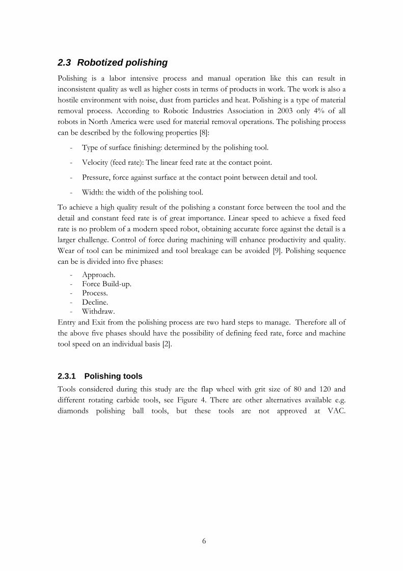
2.3 Robotized polishing
Polishing is a labor intensive process and manual operation like this can result in
inconsistent quality as well as higher costs in terms of products in work. The work is also a
hostile environment with noise, dust from particles and heat. Polishing is a type of material
removal process. According to Robotic Industries Association in 2003 only 4% of all
robots in North America were used for material removal operations. The polishing process
can be described by the following properties [8]:
- Type of surface finishing: determined by the polishing tool.
- Velocity (feed rate): The linear feed rate at the contact point.
- Pressure, force against surface at the contact point between detail and tool.
- Width: the width of the polishing tool.
To achieve a high quality result of the polishing a constant force between the tool and the
detail and constant feed rate is of great importance. Linear speed to achieve a fixed feed
rate is no problem of a modern speed robot, obtaining accurate force against the detail is a
larger challenge. Control of force during machining will enhance productivity and quality.
Wear of tool can be minimized and tool breakage can be avoided [9]. Polishing sequence
can be is divided into five phases:
- Approach. - Force Build-up. - Process. - Decline. - Withdraw.
Entry and Exit from the polishing process are two hard steps to manage. Therefore all of
the above five phases should have the possibility of defining feed rate, force and machine
tool speed on an individual basis [2].
2.3.1 Polishing tools
Tools considered during this study are the flap wheel with grit size of 80 and 120 and
different rotating carbide tools, see Figure 4. There are other alternatives available e.g.
diamonds polishing ball tools, but these tools are not approved at VAC.

7
Figure 4 Flap wheel and rotating carbide tool.
The flap wheel adds compliance to the system by the natural compliance of the flaps.
Limited lifetime may be an issue, but it is inexpensive. The wear of the flap wheel is not an
issue since the force control should be able to correct this deviation. The flap wheel is able
to leave a smooth surface (grain size depending) but is not as good at removing material as
most rotating carbide tools. During the tests the flap wheel is slightly tilted to achieve a
more even wear of the tool. A rotating carbide tool is a good choice when there is not
enough space available for the rotating flap wheels.
2.3.2 Path planning
An automatic polishing system requires support for the generation of collision-free robot
trajectories [8]. Surfaces on components to be polished can be of complex shapes in three
dimensions as well as large tolerances in the cast industry makes it hard or impossible using
other than manual labor until now when introducing robots with force control. To define
an accurate polishing robot path hundreds of coordinates and orientations may be needed.
Without proper software aids this work of defining these points would be tedious. Path
planning tools can be divided into off-line and on-line. Off-line planning can be done in
software tools such as RobotStudio [1] and Tecnomatix Process Simulate [10]. CAD
models of the detail are analyzed and used to design paths along the detail. The paths are
then used to generate robot code, e.g.. RAPID Code. RobotStudio has an option,
Machining PowerPac [11]. The PowerPac aids the user with wizards to develop machining
applications. ABB’s force control package RobotWare for Machining FC (force control)
offers the user to define coarse points on-line (within a couple of mm). The points can be
defined by the operator “dragging” the robot arm around to the correct spots while the
robot is in a soft mode. The rough points are then used as input when the robot learns the
path by an auto-learn sequence. The sequence utilizes the force sensor to detect the
edges/surfaces of the work piece. The result of the off-line path generation can be
calibrated and updated through the on-line auto-learning sequence. The different
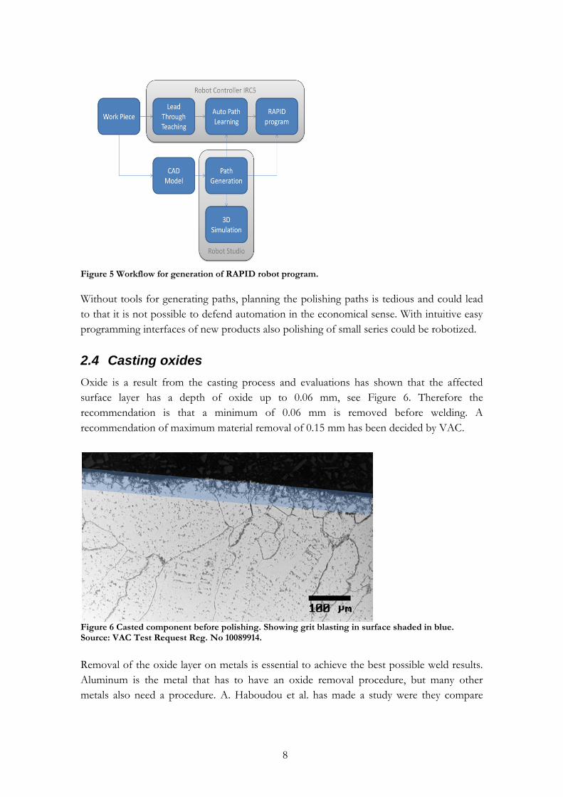
procedures to generate RAPID program for polishing is shown in Figure 5.
8
Figure 5 Workflow for generation of RAPID robot program.
Without tools for generating paths, planning the polishing paths is tedious and could lead
to that it is not possible to defend automation in the economical sense. With intuitive easy
programming interfaces of new products also polishing of small series could be robotized.
2.4 Casting oxides
Oxide is a result from the casting process and evaluations has shown that the affected
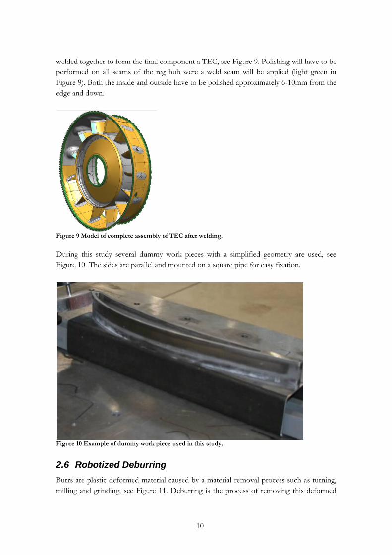
surface layer has a depth of oxide up to 0.06 mm, see Figure 6. Therefore the
recommendation is that a minimum of 0.06 mm is removed before welding. A
recommendation of maximum material removal of 0.15 mm has been decided by VAC.
Figure 6 Casted component before polishing. Showing grit blasting in surface shaded in blue. Source: VAC Test Request Reg. No 10089914.
Removal of the oxide layer on metals is essential to achieve the best possible weld results.
Aluminum is the metal that has to have an oxide removal procedure, but many other
metals also need a procedure. A. Haboudou et al. has made a study were they compare

9
polishing, sand blasting and YAG laser as surface preparation on aluminium [12]. There are
two common procedures in the industry today, chemical and mechanical removal. There
are many different methods for each. The mechanical procedure can be divided into sand-
blasting (different sands), scraping, wire brushing, grinding, filing and polishing (different
tools). A disadvantage of chemical processes is that the chemical waste has to be taken care
of. The mechanical procedure has the disadvantages of dust and noise. There is methods
under research that does not have these disadvantages, like low pressure arc [13]. Dust and
noise is not taken into consideration in this study were the process is robotized.
Previous trials at VAC with manual polishing using a flap wheel grain size P150 and speed
of 4500 rpm has given a result of 0.04-0.05 mm of removed material, see Figure 7.
Therefore tools with larger grain size (P80 and P120) will be utilized in trials with the robot
cell.
Figure 7 Casted Component after manual polishing, material removed is 0.04-0.05 mm.
2.5 Components
The component in this study that will be object to an oxide removal procedure is called a
reg hub, see Figure 8.
Figure 8 Model of reg hub, component to be polished at side of the green top surface.
It consists of Inconel 718® a nickel-based alloy with good weld-ability compared to the
nickel-based alloys with aluminum and titanium. The reg hub is to be plasma welded to a
vane and an elliptic metal sheet to form a curved H-beam (segment). These segments are
10
welded together to form the final component a TEC, see Figure 9. Polishing will have to be
performed on all seams of the reg hub were a weld seam will be applied (light green in
Figure 9). Both the inside and outside have to be polished approximately 6-10mm from the
edge and down.
Figure 9 Model of complete assembly of TEC after welding.
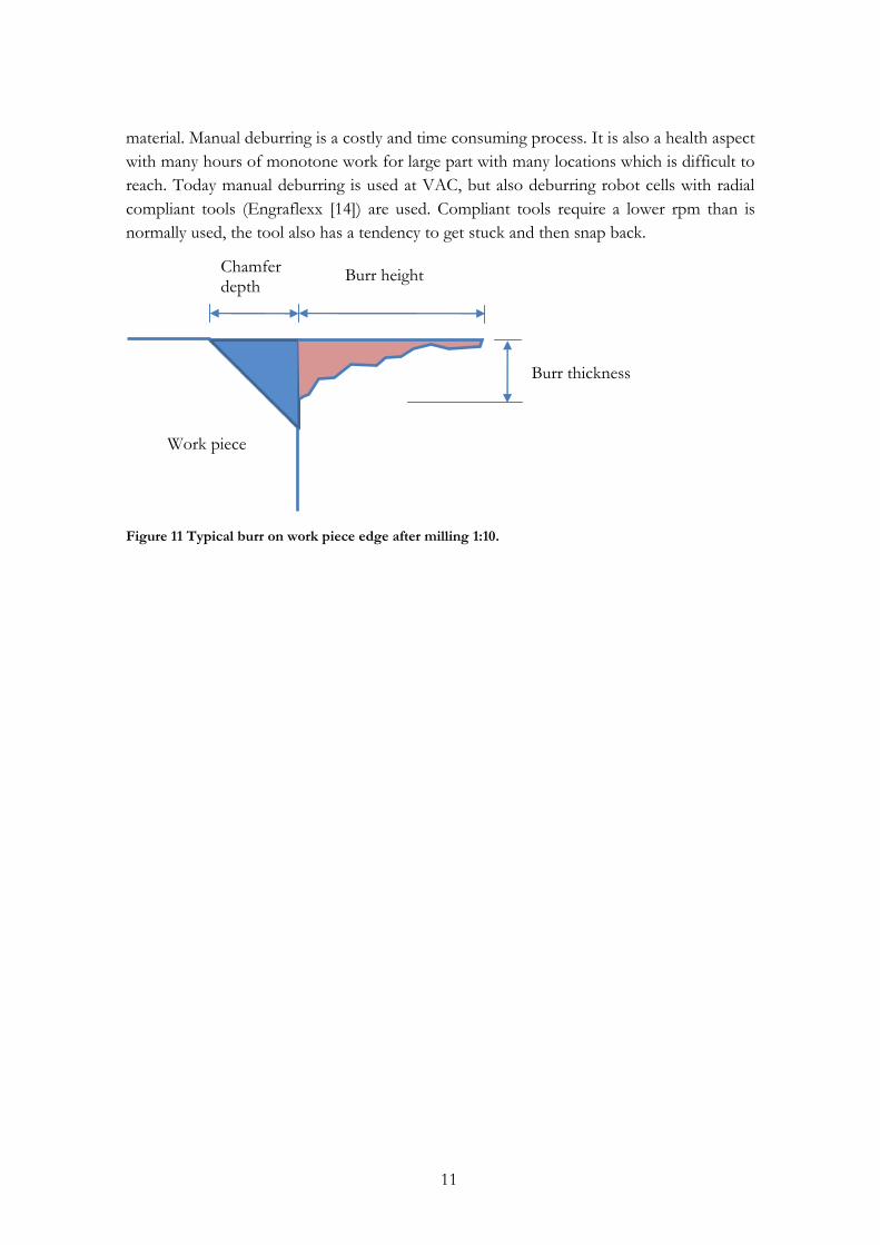
During this study several dummy work pieces with a simplified geometry are used, see
Figure 10. The sides are parallel and mounted on a square pipe for easy fixation.
Figure 10 Example of dummy work piece used in this study.
2.6 Robotized Deburring
Burrs are plastic deformed material caused by a material removal process such as turning,
milling and grinding, see Figure 11. Deburring is the process of removing this deformed
11
material. Manual deburring is a costly and time consuming process. It is also a health aspect
with many hours of monotone work for large part with many locations which is difficult to
reach. Today manual deburring is used at VAC, but also deburring robot cells with radial
compliant tools (Engraflexx [14]) are used. Compliant tools require a lower rpm than is
normally used, the tool also has a tendency to get stuck and then snap back.
Figure 11 Typical burr on work piece edge after milling 1:10.
Work piece
Burr thickness
Burr height Chamfer depth
12
3 Experimental robot system setup
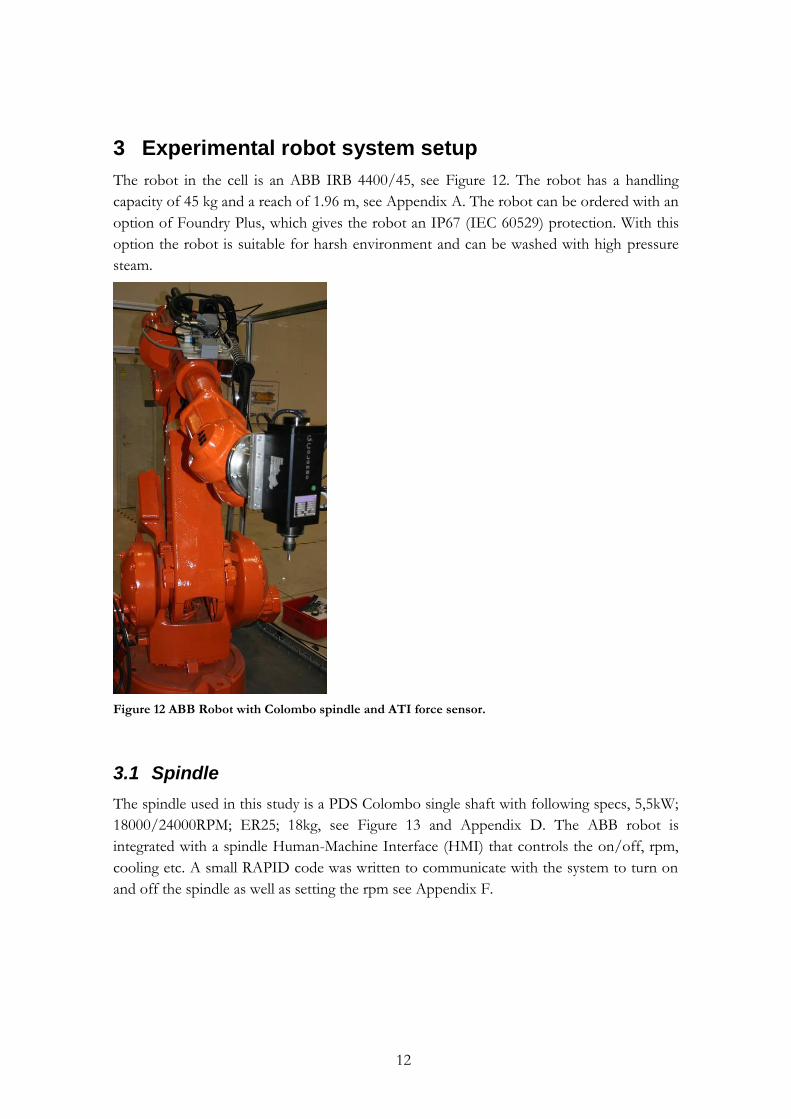
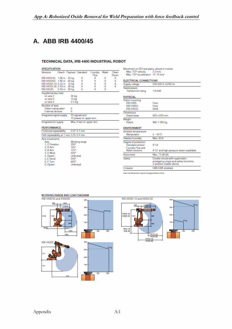
The robot in the cell is an ABB IRB 4400/45, see Figure 12. The robot has a handling
capacity of 45 kg and a reach of 1.96 m, see Appendix A. The robot can be ordered with an
option of Foundry Plus, which gives the robot an IP67 (IEC 60529) protection. With this
option the robot is suitable for harsh environment and can be washed with high pressure
steam.
Figure 12 ABB Robot with Colombo spindle and ATI force sensor.
3.1 Spindle
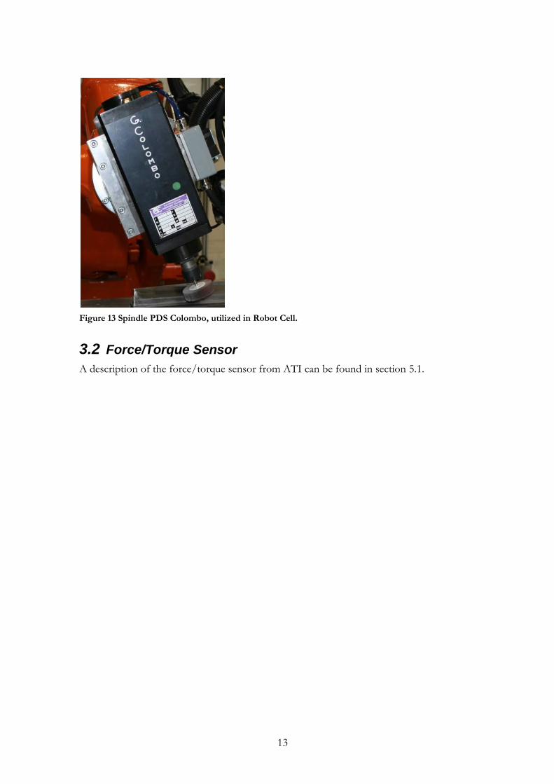
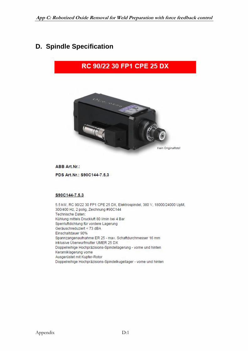
The spindle used in this study is a PDS Colombo single shaft with following specs, 5,5kW;
18000/24000RPM; ER25; 18kg, see Figure 13 and Appendix D. The ABB robot is
integrated with a spindle Human-Machine Interface (HMI) that controls the on/off, rpm,
cooling etc. A small RAPID code was written to communicate with the system to turn on
and off the spindle as well as setting the rpm see Appendix F.
13
Figure 13 Spindle PDS Colombo, utilized in Robot Cell.
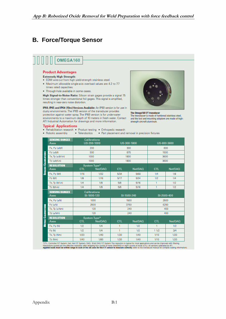
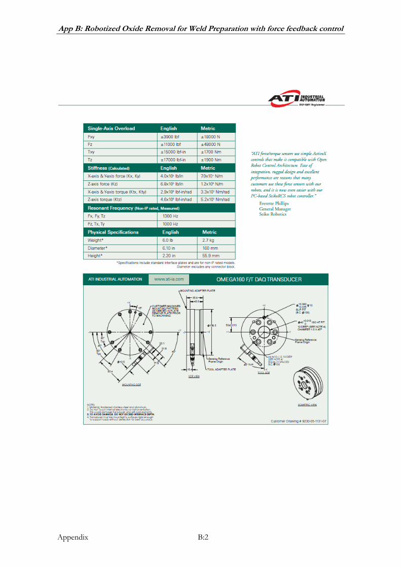
3.2 Force/Torque Sensor
A description of the force/torque sensor from ATI can be found in section 5.1.
14
4 Robot programming, force control
The Force Control for Machining application [15] includes two different options; Pressure
Control or Speed Control. Using FC SpeedChange, machining speed is reduced when
process force exceeds a limit value. Our application will however utilize the FC Pressure.
FC Pressure is maintaining a constant pressure against a work piece while moving along the
surface.
4.1 On-line programming
The on-line programming of the robot is done through the following steps:
Force Control Payload is automatically identified by robot controller while moving axes
five and six to their maximum positions in free air. This has only to be done once as long
as the tool is the same.
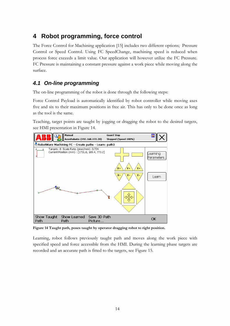
Teaching, target points are taught by jogging or dragging the robot to the desired targets,
see HMI presentation in Figure 14.
Figure 14 Taught path, poses taught by operator dragging robot to right position.
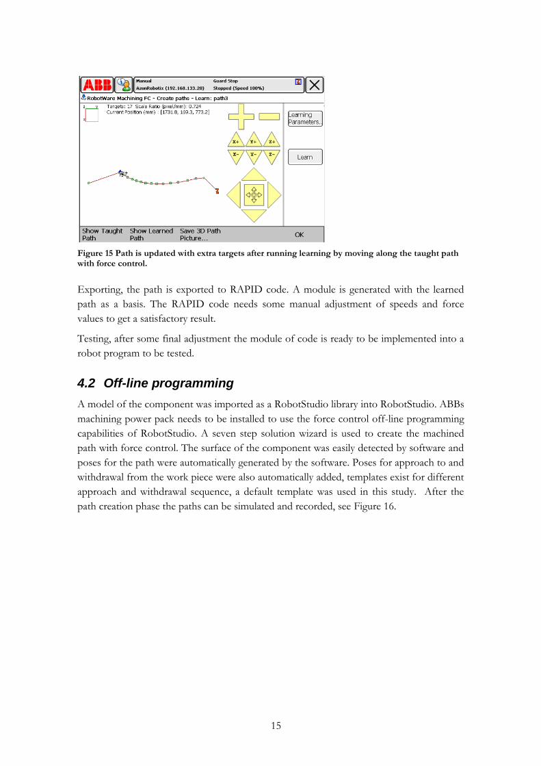
Learning, robot follows previously taught path and moves along the work piece with
specified speed and force accessible from the HMI. During the learning phase targets are
recorded and an accurate path is fitted to the targets, see Figure 15.
15
Figure 15 Path is updated with extra targets after running learning by moving along the taught path with force control.
Exporting, the path is exported to RAPID code. A module is generated with the learned
path as a basis. The RAPID code needs some manual adjustment of speeds and force
values to get a satisfactory result.
Testing, after some final adjustment the module of code is ready to be implemented into a
robot program to be tested.
4.2 Off-line programming
A model of the component was imported as a RobotStudio library into RobotStudio. ABBs
machining power pack needs to be installed to use the force control off-line programming
capabilities of RobotStudio. A seven step solution wizard is used to create the machined
path with force control. The surface of the component was easily detected by software and
poses for the path were automatically generated by the software. Poses for approach to and
withdrawal from the work piece were also automatically added, templates exist for different
approach and withdrawal sequence, a default template was used in this study. After the
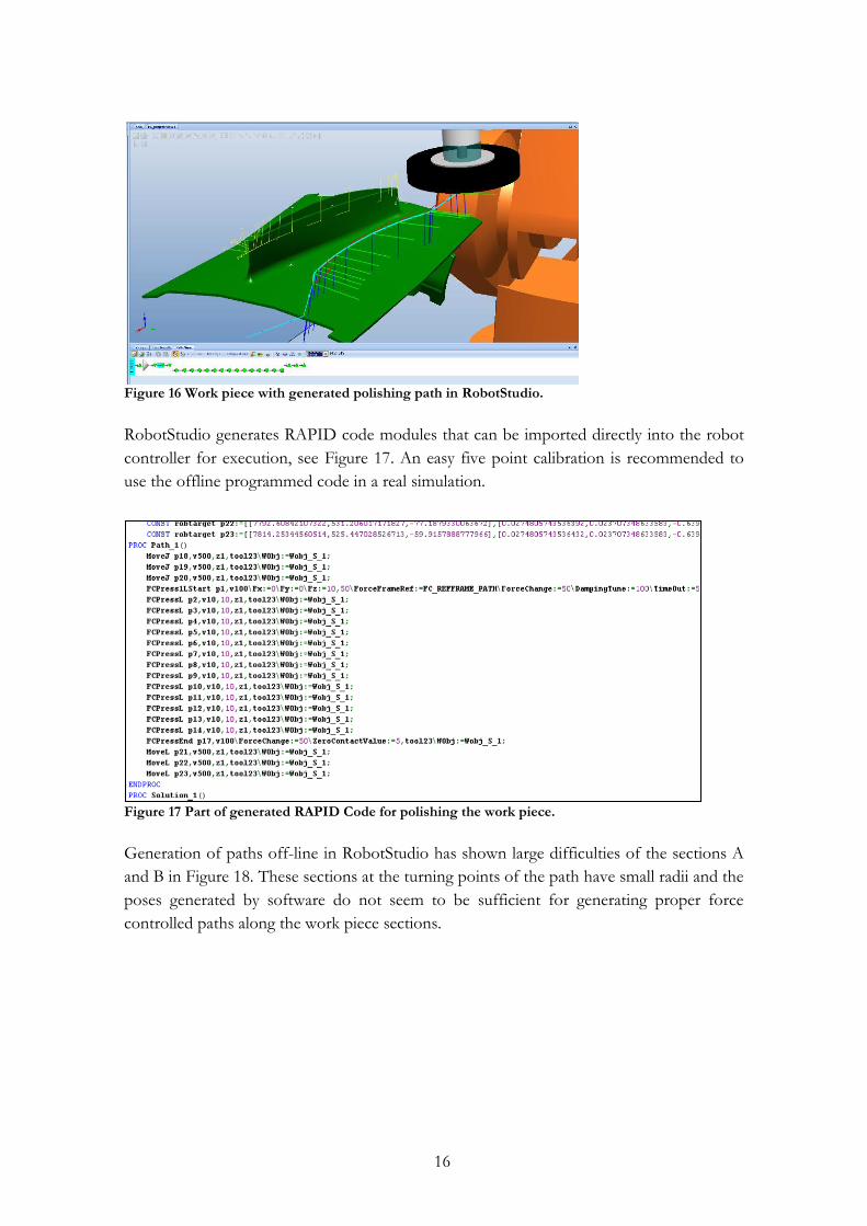
path creation phase the paths can be simulated and recorded, see Figure 16.
16
Figure 16 Work piece with generated polishing path in RobotStudio.
RobotStudio generates RAPID code modules that can be imported directly into the robot
controller for execution, see Figure 17. An easy five point calibration is recommended to
use the offline programmed code in a real simulation.
Figure 17 Part of generated RAPID Code for polishing the work piece.
Generation of paths off-line in RobotStudio has shown large difficulties of the sections A
and B in Figure 18. These sections at the turning points of the path have small radii and the
poses generated by software do not seem to be sufficient for generating proper force
controlled paths along the work piece sections.
17
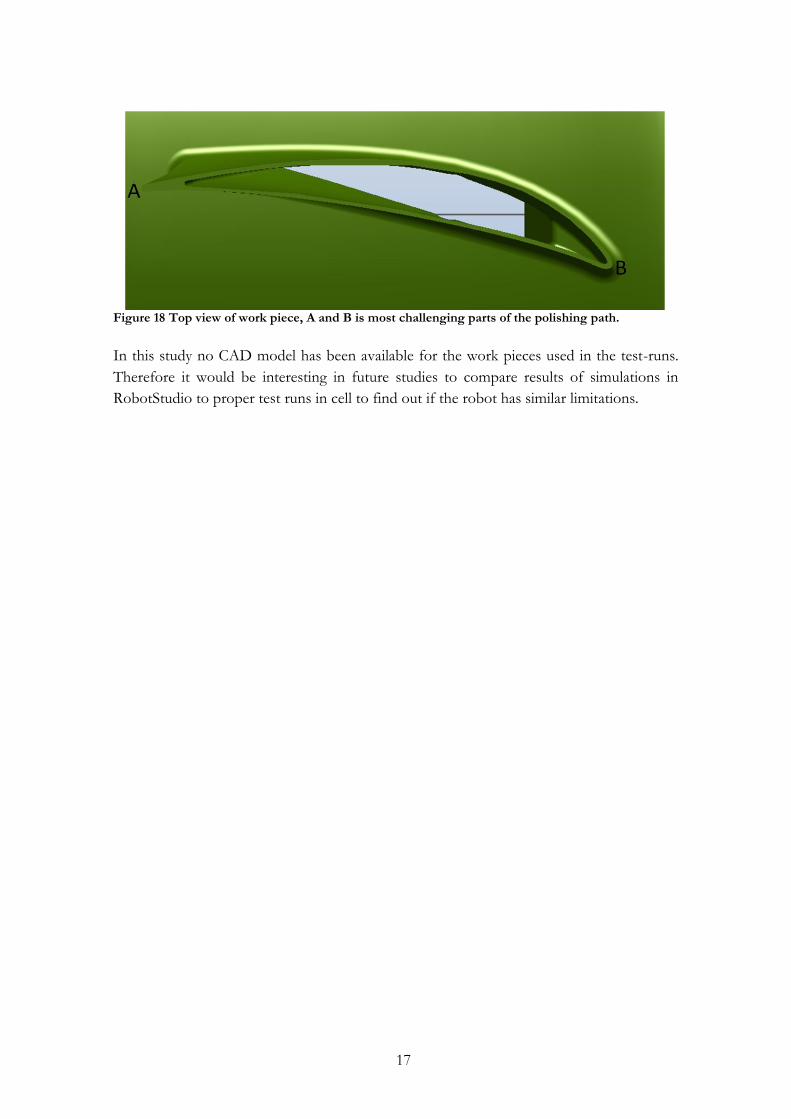
Figure 18 Top view of work piece, A and B is most challenging parts of the polishing path.
In this study no CAD model has been available for the work pieces used in the test-runs.
Therefore it would be interesting in future studies to compare results of simulations in
RobotStudio to proper test runs in cell to find out if the robot has similar limitations.
18
5 Data collection/measurements
To be able to measure and analyze the result of the polishing process, a number of
measurements are performed before, during and after the test runs.
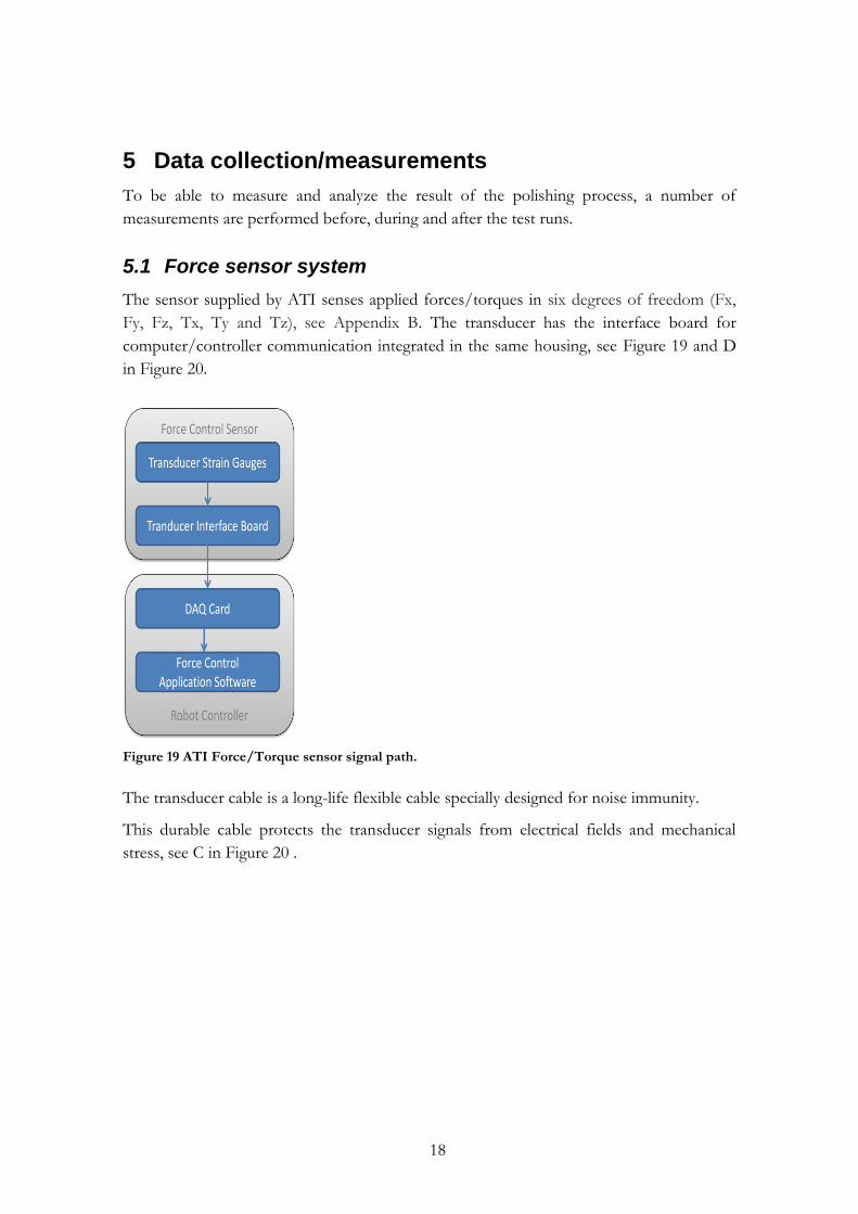
5.1 Force sensor system
The sensor supplied by ATI senses applied forces/torques in six degrees of freedom (Fx,
Fy, Fz, Tx, Ty and Tz), see Appendix B. The transducer has the interface board for
computer/controller communication integrated in the same housing, see Figure 19 and D
in Figure 20.
Figure 19 ATI Force/Torque sensor signal path.
The transducer cable is a long-life flexible cable specially designed for noise immunity.
This durable cable protects the transducer signals from electrical fields and mechanical
stress, see C in Figure 20 .

19
Figure 20 ABB controller IRC5 and force/torque sensor.
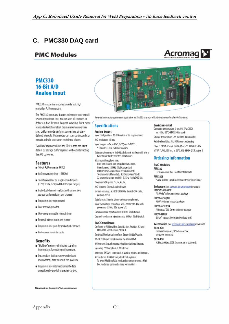
The PMC330 DAQ is a PCI card which resides in a PMC card, see Appendix C. The DAQ
card has a 16-bit A/D converter, with a recommended sampling rate at 11 kHz.
5.2 Logging of Forces
Forces were logged using ABB Test Signal Viewer [16]. The software is logging signals
through an Ethernet cable connected to the robot controller. The software can log up to
12 channels with 6 signals simultaneously with a sampling time down to 4 ms for the three
forces and torques.
5.3 Logging of Spindle motor current
The spindle’s rotational speed is controlled by a variable frequency drive (VFD). The VFD
has two analogue outputs connected to a distributed I/O node connected to the robot.
The outputs are speed of the spindle and spindle motor current. The motor current was
logged during the test-runs.
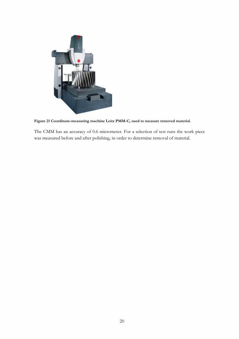
5.4 Coordinate-measuring machine
A coordinate measuring machine (CMM) Leitz PMM-C at Hexagon Metrology was utilized
to do measurement of the amount of removed material, see Figure 21.
20
Figure 21 Coordinate-measuring machine Leitz PMM-C, used to measure removed material.
The CMM has an accuracy of 0.6 micrometer. For a selection of test runs the work piece
was measured before and after polishing, in order to determine removal of material.
21
6 Results
In this section the result of the test runs in the robot cell is presented. The results are
divided into results for FC Pressure and FC SpeedChange. The FC Pressure is used for
polishing and FC SpeedChange is used for deburring. For example of the structure of
RAPID code see Appendix E and F.
6.1 FC Pressure
FC Pressure is used by introducing a number of application specific instructions in the
RAPID code: FCPress1LStart, FCPress and FCPressEnd.
FCPress1LStart is starting the approach and force build-up sequence. The tool is
approaching the work piece to build up an introductive pressure.
FCPressL is similar RAPID MoveL instruction, with a process parameter for pressure.
FCPressEnd is starting the decline and withdrawal sequence. The tool is declining force
and withdrawing from the work piece.
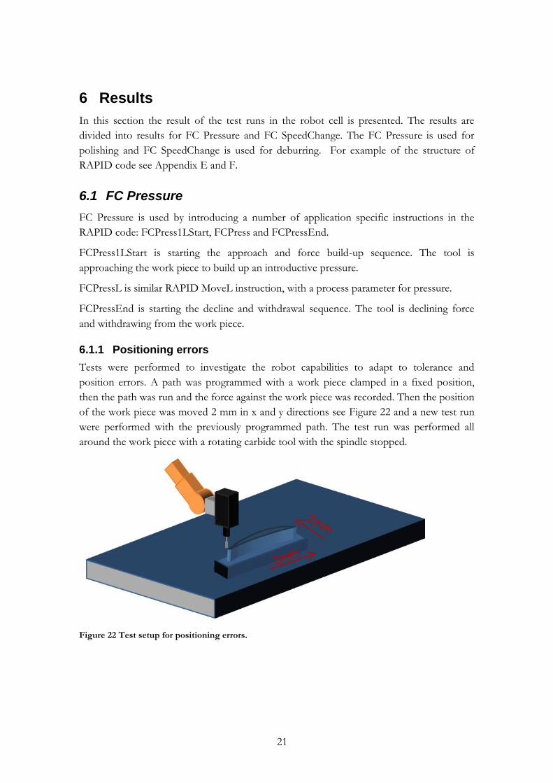
6.1.1 Positioning errors
Tests were performed to investigate the robot capabilities to adapt to tolerance and
position errors. A path was programmed with a work piece clamped in a fixed position,
then the path was run and the force against the work piece was recorded. Then the position
of the work piece was moved 2 mm in x and y directions see Figure 22 and a new test run
were performed with the previously programmed path. The test run was performed all
around the work piece with a rotating carbide tool with the spindle stopped.
Figure 22 Test setup for positioning errors.
22
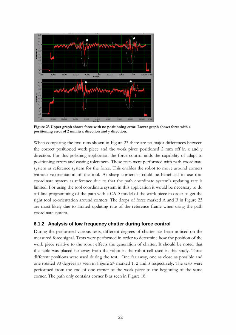
Figure 23 Upper graph shows force with no positioning error. Lower graph shows force with a positioning error of 2 mm in x direction and y direction.
When comparing the two runs shown in Figure 23 there are no major differences between
the correct positioned work piece and the work piece positioned 2 mm off in x and y
direction. For this polishing application the force control adds the capability of adapt to
positioning errors and casting tolerances. These tests were performed with path coordinate
system as reference system for the force. This enables the robot to move around corners
without re-orientation of the tool. At sharp corners it could be beneficial to use tool
coordinate system as reference due to that the path coordinate system’s updating rate is
limited. For using the tool coordinate system in this application it would be necessary to do
off-line programming of the path with a CAD model of the work piece in order to get the
right tool re-orientation around corners. The drops of force marked A and B in Figure 23
are most likely due to limited updating rate of the reference frame when using the path
coordinate system.
6.1.2 Analysis of low frequency chatter during force control
During the performed various tests, different degrees of chatter has been noticed on the
measured force signal. Tests were performed in order to determine how the position of the
work piece relative to the robot effects the generation of chatter. It should be noted that
the table was placed far away from the robot in the robot cell used in this study. Three
different positions were used during the test. One far away, one as close as possible and
one rotated 90 degrees as seen in Figure 24 marked 1, 2 and 3 respectively. The tests were
performed from the end of one corner of the work piece to the beginning of the same
corner. The path only contains corner B as seen in Figure 18.

23
Figure 24 Setup for position tests.
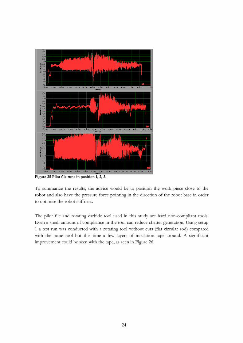
With position 1 the chatter increased up to the point of the corner (the dip in the curve is
the corner of the work piece) and after the corner the chatter decreased, see Figure 25. The
set-point force was 15 N. The chatter measured by force sensor is between ±5-10 N. The
second test the work piece was placed as close as possible to the robot. An improvement
could be seen in the beginning but around the corner the chatter increases to the same
levels as before.
The last work piece placement test was rotated 90 degrees. This was done to investigate the
stiffness of robot in different directions. This position resulted in larger chatter levels than
the previous tests. It is also noted that visible vibrations of the robot cell and robot
structure were observed. During test 3 robot axes 2 and 3 move while axis 1 is barely
moving.
24
Figure 25 Pilot file runs in position 1, 2, 3.
To summarize the results, the advice would be to position the work piece close to the
robot and also have the pressure force pointing in the direction of the robot base in order
to optimise the robot stiffness.
The pilot file and rotating carbide tool used in this study are hard non-compliant tools.
Even a small amount of compliance in the tool can reduce chatter generation. Using setup
1 a test run was conducted with a rotating tool without cuts (flat circular rod) compared
with the same tool but this time a few layers of insulation tape around. A significant
improvement could be seen with the tape, as seen in Figure 26.
25
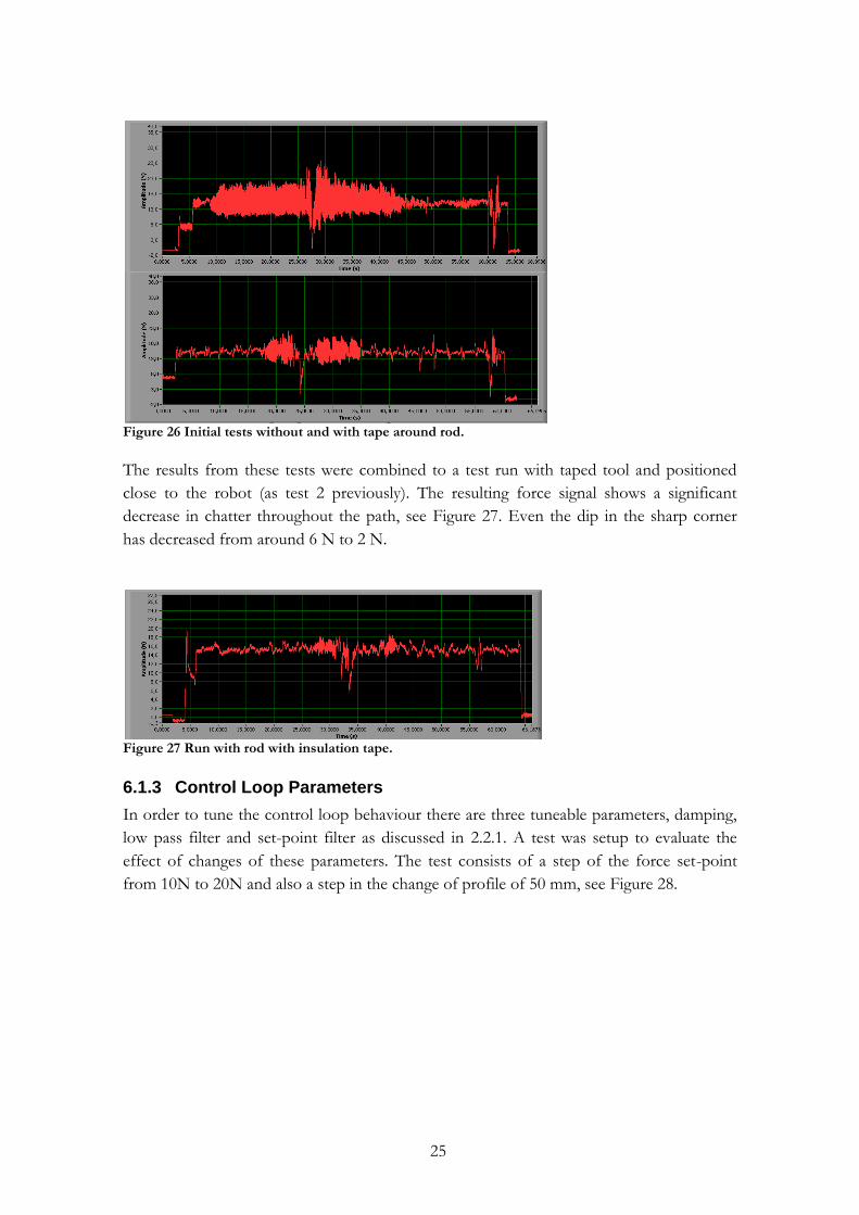
Figure 26 Initial tests without and with tape around rod.
The results from these tests were combined to a test run with taped tool and positioned
close to the robot (as test 2 previously). The resulting force signal shows a significant
decrease in chatter throughout the path, see Figure 27. Even the dip in the sharp corner
has decreased from around 6 N to 2 N.
Figure 27 Run with rod with insulation tape.
6.1.3 Control Loop Parameters
In order to tune the control loop behaviour there are three tuneable parameters, damping,
low pass filter and set-point filter as discussed in 2.2.1. A test was setup to evaluate the
effect of changes of these parameters. The test consists of a step of the force set-point
from 10N to 20N and also a step in the change of profile of 50 mm, see Figure 28.
26
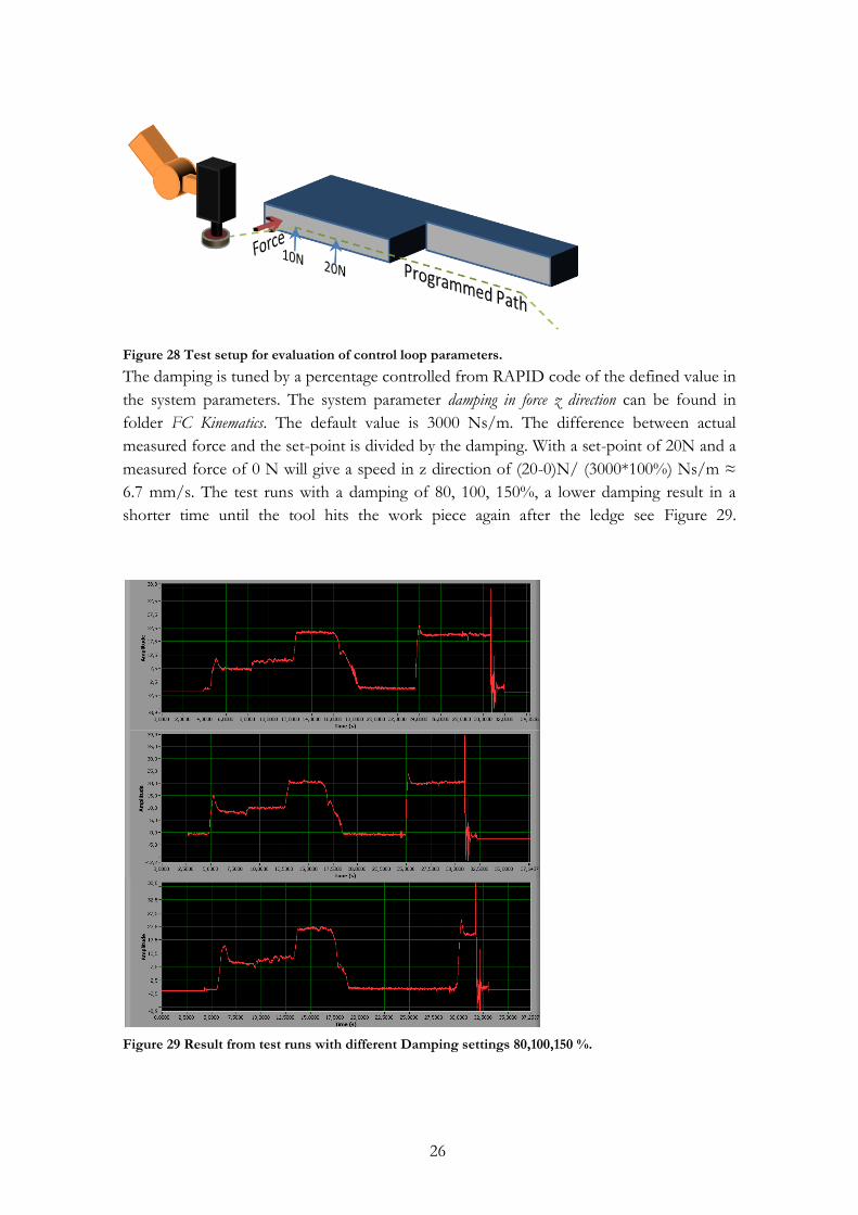
Figure 28 Test setup for evaluation of control loop parameters.
The damping is tuned by a percentage controlled from RAPID code of the defined value in
the system parameters. The system parameter damping in force z direction can be found in
folder FC Kinematics. The default value is 3000 Ns/m. The difference between actual
measured force and the set-point is divided by the damping. With a set-point of 20N and a
measured force of 0 N will give a speed in z direction of (20-0)N/ (3000*100%) Ns/m ≈
6.7 mm/s. The test runs with a damping of 80, 100, 150%, a lower damping result in a
shorter time until the tool hits the work piece again after the ledge see Figure 29.
Figure 29 Result from test runs with different Damping settings 80,100,150 %.
27
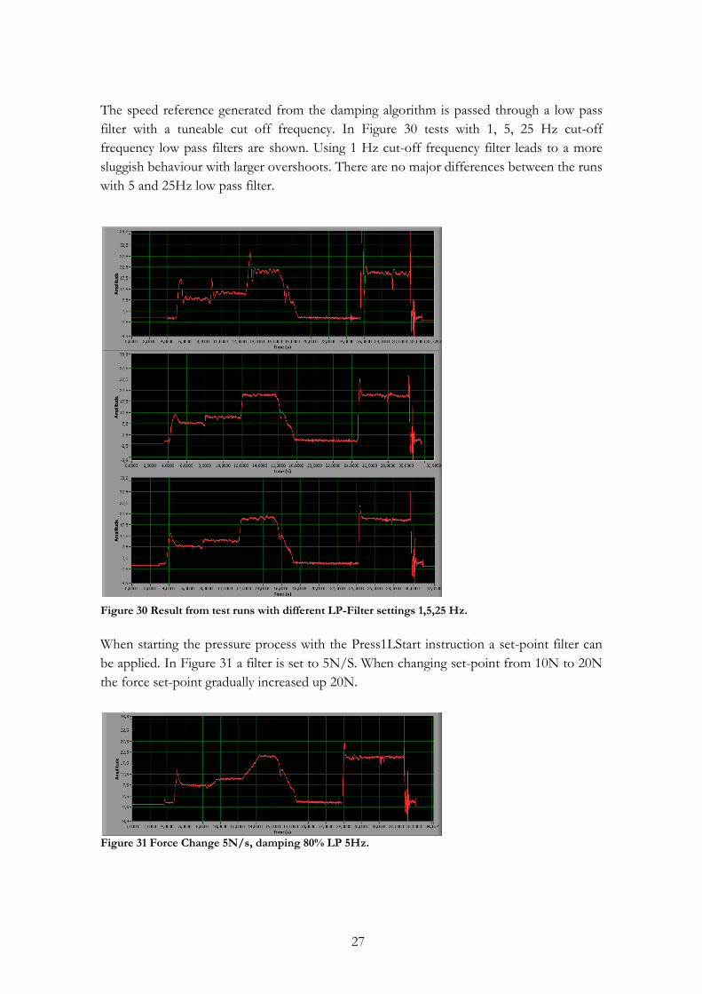
The speed reference generated from the damping algorithm is passed through a low pass
filter with a tuneable cut off frequency. In Figure 30 tests with 1, 5, 25 Hz cut-off
frequency low pass filters are shown. Using 1 Hz cut-off frequency filter leads to a more
sluggish behaviour with larger overshoots. There are no major differences between the runs
with 5 and 25Hz low pass filter.
Figure 30 Result from test runs with different LP-Filter settings 1,5,25 Hz.
When starting the pressure process with the Press1LStart instruction a set-point filter can
be applied. In Figure 31 a filter is set to 5N/S. When changing set-point from 10N to 20N
the force set-point gradually increased up 20N.
Figure 31 Force Change 5N/s, damping 80% LP 5Hz.
28
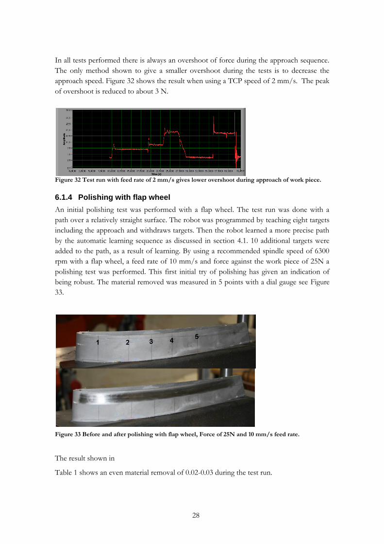
In all tests performed there is always an overshoot of force during the approach sequence.
The only method shown to give a smaller overshoot during the tests is to decrease the
approach speed. Figure 32 shows the result when using a TCP speed of 2 mm/s. The peak
of overshoot is reduced to about 3 N.
Figure 32 Test run with feed rate of 2 mm/s gives lower overshoot during approach of work piece.
6.1.4 Polishing with flap wheel
An initial polishing test was performed with a flap wheel. The test run was done with a
path over a relatively straight surface. The robot was programmed by teaching eight targets
including the approach and withdraws targets. Then the robot learned a more precise path
by the automatic learning sequence as discussed in section 4.1. 10 additional targets were
added to the path, as a result of learning. By using a recommended spindle speed of 6300
rpm with a flap wheel, a feed rate of 10 mm/s and force against the work piece of 25N a
polishing test was performed. This first initial try of polishing has given an indication of
being robust. The material removed was measured in 5 points with a dial gauge see Figure
33.
Figure 33 Before and after polishing with flap wheel, Force of 25N and 10 mm/s feed rate.
The result shown in
Table 1 shows an even material removal of 0.02-0.03 during the test run.
29
Table 1 Material removed (thickness) during test run, Force 25N and 10 mm/s feed rate.
Point Material Removed
1 0.03 mm
2 0.03 mm
3 0.03 mm
4 0.02 mm
5 0.02 mm
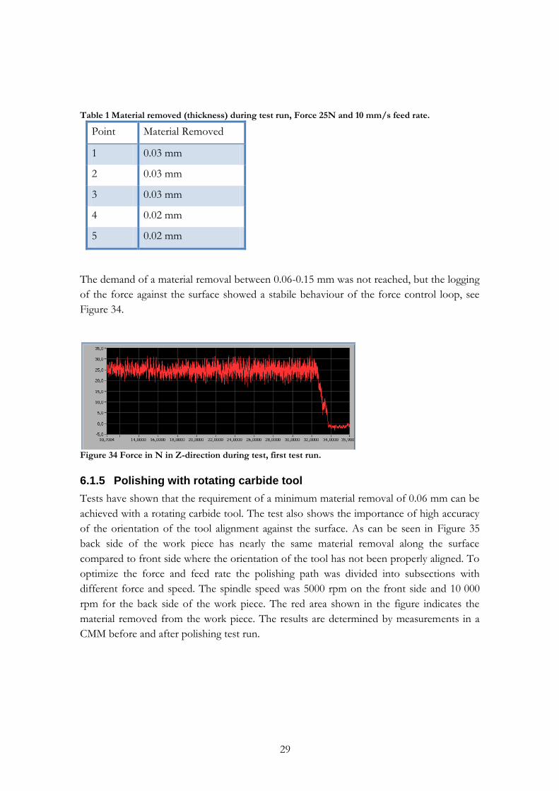
The demand of a material removal between 0.06-0.15 mm was not reached, but the logging
of the force against the surface showed a stabile behaviour of the force control loop, see
Figure 34.
Figure 34 Force in N in Z-direction during test, first test run.
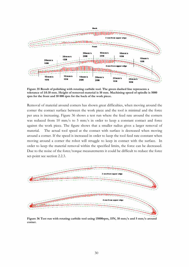
6.1.5 Polishing with rotating carbide tool
Tests have shown that the requirement of a minimum material removal of 0.06 mm can be
achieved with a rotating carbide tool. The test also shows the importance of high accuracy
of the orientation of the tool alignment against the surface. As can be seen in Figure 35
back side of the work piece has nearly the same material removal along the surface
compared to front side where the orientation of the tool has not been properly aligned. To
optimize the force and feed rate the polishing path was divided into subsections with
different force and speed. The spindle speed was 5000 rpm on the front side and 10 000
rpm for the back side of the work piece. The red area shown in the figure indicates the
material removed from the work piece. The results are determined by measurements in a
CMM before and after polishing test run.
30
Figure 35 Result of polishing with rotating carbide tool. The green dashed line represents a tolerance of ±0.10 mm. Height of removed material is 10 mm. Machining speed of spindle is 5000 rpm for the front and 10 000 rpm for the back of the work piece.
Removal of material around corners has shown great difficulties, when moving around the
corner the contact surface between the work piece and the tool is minimal and the force
per area is increasing. Figure 36 shows a test run where the feed rate around the corners
was reduced from 10 mm/s to 5 mm/s in order to keep a constant contact and force
against the work piece. The figure shows that a smaller radius gives a larger removal of
material. The actual tool speed at the contact with surface is decreased when moving
around a corner. If the speed is increased in order to keep the tool feed rate constant when
moving around a corner the robot will struggle to keep in contact with the surface. In
order to keep the material removal within the specified limits, the force can be decreased.
Due to the noise of the force/torque measurements it could be difficult to reduce the force
set-point see section 2.2.3.
Figure 36 Test run with rotating carbide tool using 15000rpm, 15N, 10 mm/s and 5 mm/s around corner.
31
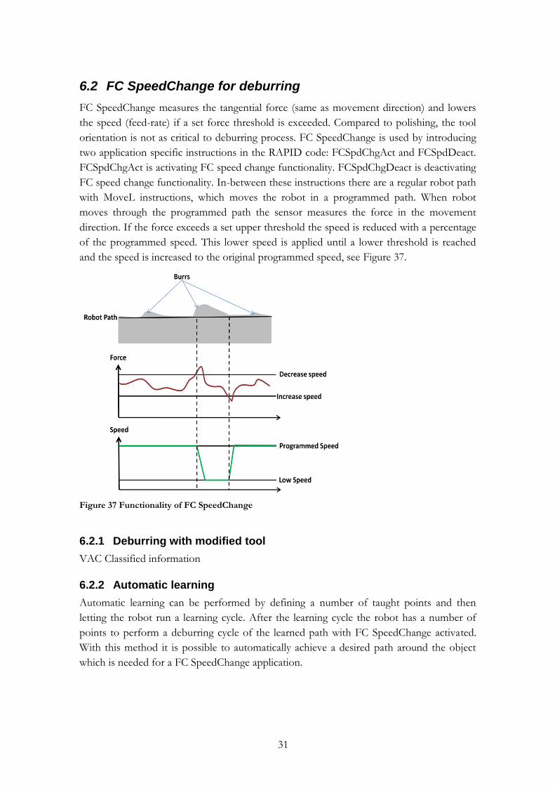
6.2 FC SpeedChange for deburring
FC SpeedChange measures the tangential force (same as movement direction) and lowers
the speed (feed-rate) if a set force threshold is exceeded. Compared to polishing, the tool
orientation is not as critical to deburring process. FC SpeedChange is used by introducing
two application specific instructions in the RAPID code: FCSpdChgAct and FCSpdDeact.
FCSpdChgAct is activating FC speed change functionality. FCSpdChgDeact is deactivating
FC speed change functionality. In-between these instructions there are a regular robot path
with MoveL instructions, which moves the robot in a programmed path. When robot
moves through the programmed path the sensor measures the force in the movement
direction. If the force exceeds a set upper threshold the speed is reduced with a percentage
of the programmed speed. This lower speed is applied until a lower threshold is reached
and the speed is increased to the original programmed speed, see Figure 37.
Figure 37 Functionality of FC SpeedChange
6.2.1 Deburring with modified tool
VAC Classified information
6.2.2 Automatic learning
Automatic learning can be performed by defining a number of taught points and then
letting the robot run a learning cycle. After the learning cycle the robot has a number of
points to perform a deburring cycle of the learned path with FC SpeedChange activated.
With this method it is possible to automatically achieve a desired path around the object
which is needed for a FC SpeedChange application.
32
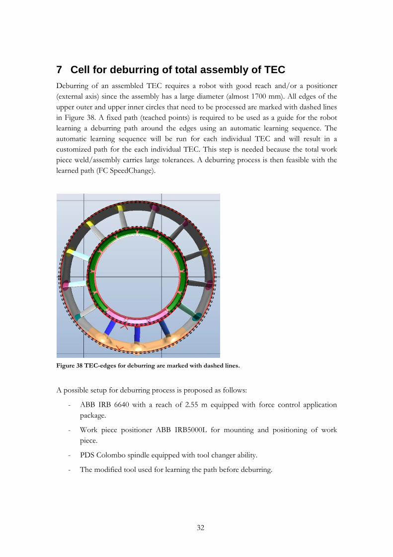
7 Cell for deburring of total assembly of TEC
Deburring of an assembled TEC requires a robot with good reach and/or a positioner
(external axis) since the assembly has a large diameter (almost 1700 mm). All edges of the
upper outer and upper inner circles that need to be processed are marked with dashed lines
in Figure 38. A fixed path (teached points) is required to be used as a guide for the robot
learning a deburring path around the edges using an automatic learning sequence. The
automatic learning sequence will be run for each individual TEC and will result in a
customized path for the each individual TEC. This step is needed because the total work
piece weld/assembly carries large tolerances. A deburring process is then feasible with the
learned path (FC SpeedChange).
Figure 38 TEC-edges for deburring are marked with dashed lines.
A possible setup for deburring process is proposed as follows:
- ABB IRB 6640 with a reach of 2.55 m equipped with force control application
package.
- Work piece positioner ABB IRB5000L for mounting and positioning of work
piece.
- PDS Colombo spindle equipped with tool changer ability.
- The modified tool used for learning the path before deburring.
33
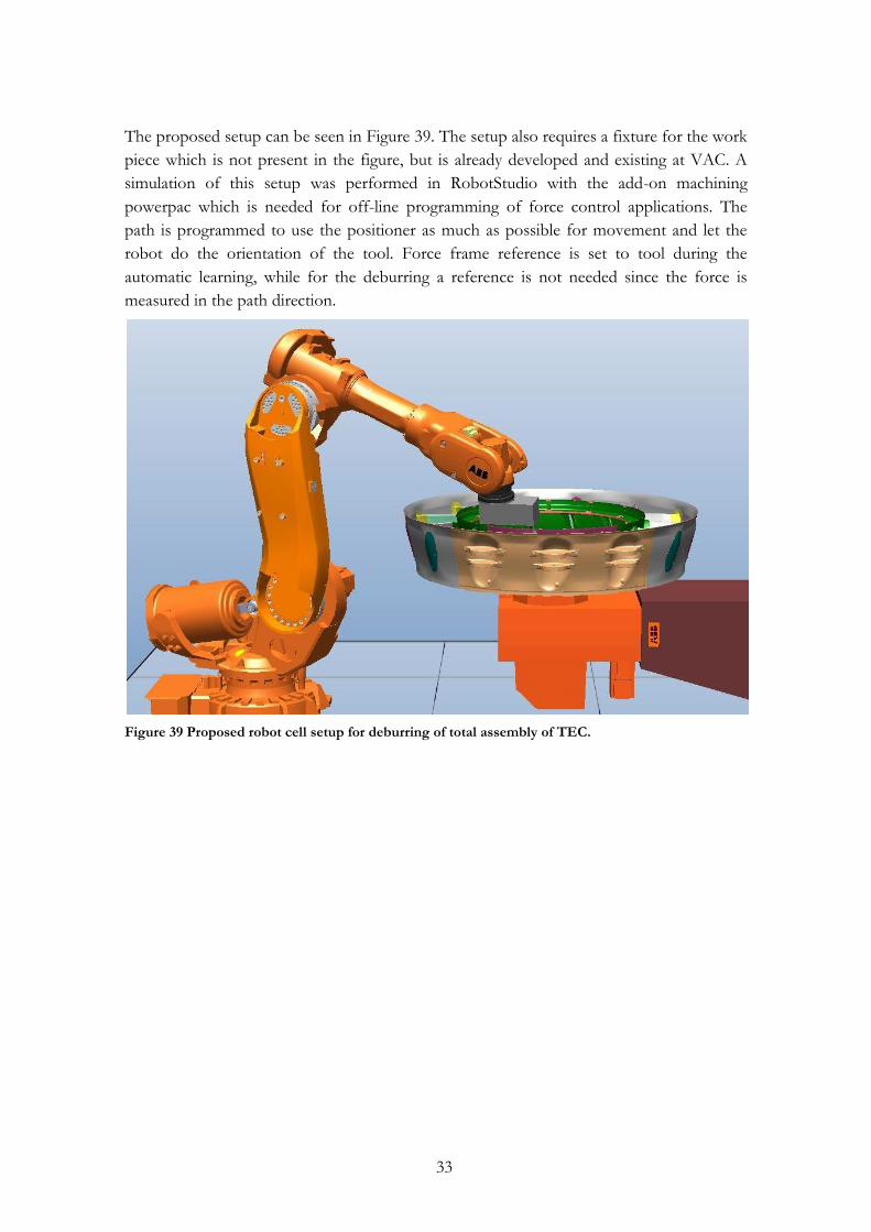
The proposed setup can be seen in Figure 39. The setup also requires a fixture for the work
piece which is not present in the figure, but is already developed and existing at VAC. A
simulation of this setup was performed in RobotStudio with the add-on machining
powerpac which is needed for off-line programming of force control applications. The
path is programmed to use the positioner as much as possible for movement and let the
robot do the orientation of the tool. Force frame reference is set to tool during the
automatic learning, while for the deburring a reference is not needed since the force is
measured in the path direction.
Figure 39 Proposed robot cell setup for deburring of total assembly of TEC.
34
8 Conclusions and future work
This study has shown that the force control technology is not mature for a polishing
process for casted aero engine structural components. Main reason is the lack of adaptation
properties available from the robot system in term of orientation. When using a rotating
carbide tool the alignment of the tool is crucial for a polished surface. Since the casting
process will give deviation of the surface perfect alignment of tool against work piece is not
possible. In discussions with ABB R&D department, there is a possibility to investigate and
develop such feature in cooperation with University West. During the study a flap wheel
was evaluated, its compliant capabilities were desirable unfortunately the rate of material
removal was too low to fulfil the requirements. The possibility of using a compliant tool
axis to align the tool against surface is an option well worth researching. This study has
been limited to the use of path frame reference during an activated pressure control due to
lack of CAD models for the work pieces. The ability to keep a constant pressure against
surface around sharp corners has shown poor results in this study. There is a possibility
that the use of tool frame references could improve the surface tracing around sharp
bends. Test of off-line programming to generate RAPID code in order to polish a work-
piece of a CAD-model work is of great interest to evaluate the path following abilities
around sharp corners.
Tests have shown the great importance of the position of the work piece and the direction
of the polishing motion in order to minimize chatter. If a non-compliant tool is planned
for a polishing process it is a strong recommendation that the utilizing of a 2-axes turn
table and position of such is investigated, in order to optimize the robot stiffness during
the polishing process. This is done to map the optimal work position/orientation of the
robot.
Tests performed of deburring have shown good results. The FC speed change application
is a straight forward and simple application. The application controls the feed-rate during
the deburring operation and reduces speed if necessary in order to remove all burrs. Due to
the large tolerances of the total assembly of a TEC, the deburring needs to be preceeded of
a learning sequencing to determine the path. During this study the learning sequence has
been initiated manually from the pedant; in an automated robot cell the learning sequence
needs to be fully automated. Discussion with ABB has resulted in a promise of a release of
RAPID code for such functionality to VAC. A reachability study has been performed in
RobotStudio, which has resulted in a proposal of possible setup for a robot cell used for
deburring of the total assembly of the TEC. A possible solution in order to eliminate the
preceeding learning sequence would be to utilize a sensor fusion control scheme of the
force sensor and a vision system or a laser distance sensor. The force sensor would control
the feed rate during the deburring operation and the vision system/laser sensor would
adjust the path.
35
References
[1] Operating manual RobotStudio 5.12, Document ID: 3HAC032104-001 Revision: B. [2] A. Robertsson, et al., "Implementation of Industrial Robot Force Control Case
Study: High Power Stub Grinding and Deburring," in Intelligent Robots and Systems, 2006 IEEE/RSJ International Conference on, 2006, pp. 2743-2748.
[3] Z. Hui, et al., "Machining with flexible manipulator: toward improving robotic machining performance," in Advanced Intelligent Mechatronics. Proceedings, 2005 IEEE/ASME International Conference on, 2005, pp. 1127-1132.
[4] M. H. Raibert and J. J. Craig, "Hybrid Position/Force Control of Manipulators," Journal of Dynamic Systems, Measurement, and Control, vol. 103, pp. 126-133, 1981.
[5] N. Hogan, "Impedance control : An approach to manipulator, part i, ii, iii," ASME Journal of Dynamic Systems, Measurement, and Control, vol. 3, pp. 1-24, 1985.
[6] A. Blomdell, et al., "Extending an industrial robot controller: implementation and applications of a fast open sensor interface," Robotics & Automation Magazine, IEEE, vol. 12, pp. 85-94, 2005.
[7] P. Zengxi and Z. Hui, "Analysis and suppression of chatter in robotic machining process," in Control, Automation and Systems, 2007. ICCAS '07. International Conference on, 2007, pp. 595-600.
[8] L. Basanez and J. Rosell, "Robotic polishing systems," Robotics & Automation Magazine, IEEE, vol. 12, pp. 35-43, 2005.
[9] H. Jianmin, et al., "Adaptive Force Control for Robotic Machining Process," in American Control Conference, 2007. ACC '07, 2007, pp. 1-6.
[10] Process Simulate (electronic). Siemens PLM Software, accessed 2010-03-20. Available: http://www.plm.automation.siemens.com/se_se/products/tecnomatix/robotics_automation/process_simulate.shtml
[11] Operating manual Machining PowerPac RobotStudio 5.12, Document ID: 3HAC030420-001 Revision: C.
[12] A. Haboudou, et al., "Reduction of porosity content generated during Nd: YAG laser welding of A356 and AA5083 aluminium alloys," Materials Science and Engineering A, vol. 363, pp. 40-52, 2003.
[13] A. Sato, et al., "Cathode Spot Movement of Low Pressure Arc Removing Oxide Layer," Discharges and Electrical Insulation in Vacuum, 2006. ISDEIV '06. International Symposium on, vol. 1, pp. 407-410, 2006.
[14] Engraflexx (electronic). Gravostar Technologies, accessed 2010-05-24. Available: http://www.gravostar.com/index.php?lang=en&ses=326e5a771957&file=1890
[15] Application manual Force Control for Machining RobotWare 5.0, Document ID: 3HAC027595-001 Revision: D.
[16] ABB Software: ABB Test Signal viewer, version 1.3.
App A: Robotized Oxide Removal for Weld Preparation with force feedback control
Appendix A:1
A. ABB IRB 4400/45
App B: Robotized Oxide Removal for Weld Preparation with force feedback control
Appendix B:1
B. Force/Torque Sensor
App B: Robotized Oxide Removal for Weld Preparation with force feedback control
Appendix B:2
App C: Robotized Oxide Removal for Weld Preparation with force feedback control
Appendix C:1
C. PMC330 DAQ card
App C: Robotized Oxide Removal for Weld Preparation with force feedback control
Appendix D:1
D. Spindle Specification

App C: Robotized Oxide Removal for Weld Preparation with force feedback control
Appendix E:1
E. FC SpeedChange RAPID code example
PROC RunPathpath1 (bool bRecover, bool bSpindleOn)
FCDeact;
IF bRecover = true THEN
FCCalib tvolvo_LD \Recovery;
ELSE
FCCalib tvolvo_LD;
ENDIF
IF bSpindleOn = true THEN
Spindle_On\nRPM:=2000;
ENDIF
MoveL T1Approach1, v50, z1,tvolvo\wobj :=wobj0;
MoveL T1Approach2, v50, z1,tvolvo\wobj :=wobj0;
MoveL T1Approach3, v5, fine,tvolvo\wobj :=wobj0;
FCSpdChgAct 50 \NonStopAllTime;
MoveL T1Process1, v10, z1,tvolvo\wobj :=wobj0;
MoveL T1Process2, v10, z1,tvolvo\wobj :=wobj0;
MoveL T1Process3, v10, z1,tvolvo\wobj :=wobj0;
MoveL T1Process4, v10, z1,tvolvo\wobj :=wobj0;
MoveL T1Process5, v10, z1,tvolvo\wobj :=wobj0;
MoveL T1Process6, v10, z1,tvolvo\wobj :=wobj0;
MoveL T1Process7, v10, z1,tvolvo\wobj :=wobj0;
MoveL T1Process8, v10, z1,tvolvo\wobj :=wobj0;
FCSpdChgDeact;
MoveL T1Withdraw1, v5, z1,tvolvo\wobj :=wobj0;
MoveL T1Withdraw2, v50, z1,tvolvo\wobj :=wobj0;
Spindle_Off;
ENDPROC
ENDMODULE

App C: Robotized Oxide Removal for Weld Preparation with force feedback control
Appendix F:1
F. FC Pressure RAPID code example
PROC RunPathpath1 (bool bRecover, bool bSpindleOn)
FCDeact;
IF bRecover = true THEN
FCCalib tflapwheel_LD \Recovery;
ELSE
FCCalib tflapwheel_LD;
ENDIF
IF bSpindleOn = true THEN
Spindle1On\nRPM:=5;
ENDIF
MoveL T1Approach1, v50, z1,tflapwheel\wobj :=wvane;
MoveL T1Approach2, v50, z1,tflapwheel\wobj :=wvane;
MoveL T1Approach3, v10, fine, tflapwheel\WObj:=wvane;
FCPress1LStart T1Process1, v10\Fx:= n1ForceX\Fy:= n1ForceY
\Fz:=n1ForceZ,50\ForceFrameRef:=FC_REFFRAME_PATH\ForceChange:=50
\DampingTune:=100\TimeOut:=5\UseSpdFFW\PosSupvDist:=9e9, z1,
tflapwheel\WObj:=wvane;
FCPressL T1Process2, v20, 15, z1, tflapwheel, \wobj:=wvane;
FCPressL T1Process3, v20, 15, z1, tflapwheel, \wobj:=wvane;
FCPressL T1Process4, v20, 15, z1, tflapwheel, \wobj:=wvane;
FCPressL T1Process5, v20, 15, z1, tflapwheel, \wobj:=wvane;
FCPressL T1Process6, v20, 15, z1, tflapwheel, \wobj:=wvane;
FCPressL T1Process7, v20, 15, z1, tflapwheel, \wobj:=wvane;
FCPressL T1Process8, v20, 15, z1, tflapwheel, \wobj:=wvane;
FCPressL T1Process9, v20, 15, z1, tflapwheel, \wobj:=wvane;
FCPressL T1Process10, v20, 15, z1, tflapwheel, \wobj:=wvane;
FCPressLEnd T1Withdraw1,v20,\ForceChange :=50,\ZeroContactValue := 7.5;
MoveL T1Withdraw2, v50, z1,tflapwheel\wobj :=wvane;
IF bSpindleOn = true THEN
Spindle1Off;
ENDIF
ENDPROC
PROC Spindle1On(\num nRPM)
VAR num nVarv;
Set doSIF_SPI_Cooling;
Set doSIF_FRC_Spd_Forward;
Set doSIF_FRC_SpindleOn;
! Spindel varv 0-10
nVarv:=5;
IF Present(nRPM) nVarv:=nRPM;
SetAO aoSIF_SPI_SpdSetpnt, nVarv;
ENDPROC
PROC Spindle1Off()
SetAO aoSIF_SPI_SpdSetpnt, 0;
WaitAi aiSIF_SPI_ActSpeed\LT, 0.03;
Reset doSIF_FRC_SpindleOn;
Reset doSIF_SPI_Cooling;
Reset doSIF_FRC_Spd_Forward;
ENDPROC
ENDMODULE