Embed Size (px)
Citation preview

Robotics Design Project
Introduction: The project will involve working in teams to design and build a robotic wheelchair using LEGO Mindstorms Robotics Invention System to compete in an obstacle course.
Problem Definition: The objective of this project is to build a computer controlled robot that can safely deliver an immobile person through an obstacle course in the shortest amount of time. To simulate real world situations, the robot must be able to climb a small ramp, cross a street without getting hit by a car, turn corners, fight off aggressive animals, climb stairs and free itself from a sandpit.
Educational Goals:
The goals of this project are as follow: 1. To provide students with hands on experience building a simple programmable robot. 2. To demonstrate that design processes typically involve a multitude of skills and
knowledge from many subject areas. 3. To familiarize students with the design process- from brainstorming, initial design,
prototyping, testing, revising, to final production and competition. 4. To allow students to experience the perilous designer/builder interface. 5. To spark student’s interest in Science and Technology.
6. To win some Money ($100 winners take all) References: LEGO MINDSOTRMS Robot , Jonathan B. Kundsen , 1st edition, 1999, O’Reilly http://www.crynwr.com/lego-robotics/ http://www.plazaearth.com/usr/gasperi/lego.htm#background http://www.oreilly.com/catalog/lmstorms/resources/index.html http://www.robotbooks.com/

Competition Guidelines The objective is to build a computer controlled Robot that can deliver an immobile person through an obstacle course in the shortest time without losing him. To simulate the real world situation, the wheelchair must be able to climb a small ramp, cross a street without getting hit by a car, turn corners, fight off aggressive animals, climb stairs and free itself from a sandpit. For a specific floor plan, please refer to the Playing Field section. The contest is also subject to a few ground rules. Please follow them carefully before begin your design.
Teams
The team will consist of three or four members. Each member is responsible for a part of the design and construction. Great emphasis will be placed on teamwork. Evaluation of contribution from each team member will play a big part in the team’s final grade.
2

Playing field The floor plan contest layout is shown in Figure 1. The playing field is on a hard concrete floor (somewhere in the Learning Factory). A wall made of cinder blocks surrounds the playing field. A 4” tall ramp is placed immediately after the starting block. It is followed by a crosswalk with two way traffic. There is a corner turn located before the robot will confront a couple unfriendly wheelchair robots. Then the course changes to an up and down stair case with 4” steps and finally finishes off with a sand pit at the end.
3

Robot Constraints: Size: The maximum size of the Robot shall be 12" by 12" by 12 ". The Robot can not look over the walls of the structure and must never extend itself beyond 12 inches in any dimension. All Robots will be carefully measured. Don't let your Robot be disqualified because it is slightly over the limit. Weight: There are no restrictions on the weight of the Robot. Functions: The robot must have the comfort and look of a regular wheelchair. The robot must be able to support and hold a passenger - monchichi (will be provided) without losing it during the crossing.
Programs:
The robot must have three programs installed on the RCX:
Program 1 - Robotic Wheelchair
This program provides the navigation for the robot to maneuver through the obstacle course. In additional to clearing the obstacles, this program needs to ensure safe passage across the crosswalk. It does this by executing Message 1 (stop) and Message 2 (start again) sent from the Master Controller* when the robot reaches the edge of the crosswalk.
Program 2 - Car
This program causes the robot to behave as a car. A car is defined as a robot that moves forward and backwards across a narrow (4 ft) passage. Additionally, it needs to be programmed to stop for crossing pedestrians (like the robotic wheelchair). It does this by executing Message 1 (move away and stop) sent from the Master Controller* when the robotic wheelchair reaches the crosswalk.
Program 3 - Defender Robot
This program requires the robot to perform certain actions in attempt to disable competing robots. This robot can have any mechanism or electronic device that can prevent the robotic wheelchair from proceeding through the obstacle course. Additionally it needs to incorporate a value from a light sensor to keep it from entering the "defense free zone".
*The Master Controller is an RCX that is programmed by the instructor. It sends out infrared signals when the robotic wheelchair passes in front of its light sensor. The "signals" do not contain directions, but alert robots in the vicinity to review content coded on their RCX. Thus, you will need to program your robot to execute the messages. It will send out a signal for robots to execute Message 1 (Wheelchair – "Stop" and Car - "Move away and stop") and then wait several seconds before sending out Message 2 (Wheelchair - "Go forward").
4
Ground Rules -------------------------------------------------------------------------------- The following set of constraints must be adhered to in the implementation of your respective designs. If you need further clarification, ask before you implement!!! -------------------------------------------------------------------------------- 1. Robots must start from rest and not to be lifted off the track during starting. 2. No human intervention is allowed during the match. 3. Your machine must be self-contained and self-sufficient. In other words, it must provide its own
energy. No "plug-ins" allowed. 4. Robots must be powered by an electric motor. No fuel engine or rocket propulsion is allowed. 5. Robots can be constructed with Lego bricks, or with any type of materials. The structure of the robot,
including wheels and legs, can be strengthened or enhanced by any means. Unless otherwise stated, there are no restrictions on the types of motors to be used.
6. You may alter any Lego parts; however, all alterations and manufacturing must be approved by
instructor. 7. Using homemade sensors or gadgets (without destroying the existing Lego parts) are encouraged.
There are numbers of Lego Mindstorms related web sites deal with homemade sensors. Some are listed in the procedure.
8. The ambient light level in the contest area is impossible to determine until the actual day of the contest.
Contestants will be given time on the contest day to make ambient light level readings if necessary to calibrate their Robot. The room will be lit by overhead florescent lamps.
9. All supplemental, not specified parts (if any) that your design uses must be accordingly priced* and
approved by your Instructor. 10. All parts necessary for your machine to be built must be itemized. 11. No competitor shall employ devices that compromise the safety of competition spectators or machines.
Machines deemed unsafe will be banned from the competition. Unsafe machines will be permitted to re-enter after the unsafe feature is removed.
12. Weapon designed to temporally disable or to throw the other team off balance is allowed. However,
device must be operated under the strict safety code of rule # 8. Devices using projectiles (tethered or otherwise), rockets, explosives, open flame, caustic chemicals, fluid or cut-off discs are strictly forbidden. BTW, Flying Robots are not permitted. The cost of the device * must be included in the calculation.
5

Tentative Schedule: Mon Wed Fri Week 7 Procedure A & B
- Introduction to final project - Instruction on basic gear mechanics and sensors - Inventory - Training video
Procedure C - Instruction on RCX code programming - Instruction on basic gear mechanics and sensors
Procedure C - Program a pathfinder for simple tasks - Guest speakers
Week 8 - Career center visit
- Pathfinder Program due
Procedure C & D - Continue programming exercise -Begin Brainstorm and Design
Week 9 Procedure D - Continue Brainstorm and Design - Design Specification due
Procedure E - Continue prototype construction
Procedure E - Continue prototype construction
Week 10 Procedure F - Trial run
Procedure G - Revision and Construction - Competition day 1
Procedure H - Competition day2 - Inventory (return
robotics Invention kit)
Final Evaluation
6
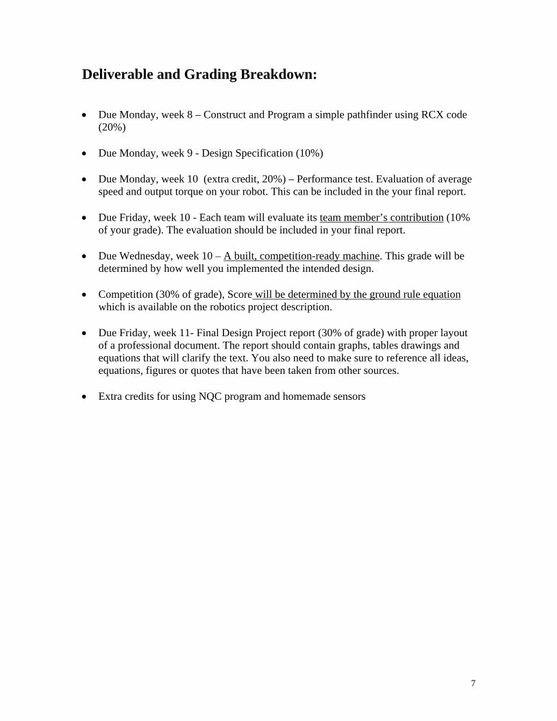
Deliverable and Grading Breakdown:
Due Monday, week 8 – Construct and Program a simple pathfinder using RCX code
(20%) Due Monday, week 9 - Design Specification (10%) Due Monday, week 10 (extra credit, 20%) – Performance test. Evaluation of average
speed and output torque on your robot. This can be included in the your final report. Due Friday, week 10 - Each team will evaluate its team member’s contribution (10%
of your grade). The evaluation should be included in your final report. Due Wednesday, week 10 – A built, competition-ready machine. This grade will be
determined by how well you implemented the intended design. Competition (30% of grade), Score will be determined by the ground rule equation
which is available on the robotics project description. Due Friday, week 11- Final Design Project report (30% of grade) with proper layout
of a professional document. The report should contain graphs, tables drawings and equations that will clarify the text. You also need to make sure to reference all ideas, equations, figures or quotes that have been taken from other sources.
Extra credits for using NQC program and homemade sensors
7
Procedure: A. Inventory
1. Check to see you have all the parts in the set The set should include:
RCX micro-computer
CD-ROM software
727 pieces of legos including:
2 motors
2 touch sensors
1 light sensor
User Guide
Constructopedia
Infrared transmitter
2. Record any shortages and overages on a sheet to be turn in to your instructor.
B. Preparation Students must go through the training exercise provided by the Robotics Invention System. The intention is to familiarize students with the software and the hardware of the kit. Please follow the instructions provided on pages 14 to 33 of the User Guide. C. Construct and program a simple pathfinder Toward the end of the training exercise, you will be asked to construct a simple sensor guided robot. Please follow the instruction on the Mindstorns video and complete the task before moving on to the part D. Tasks to be performed by the pathfinder
- Program robot to go forward for 2.5 second and set the power at 7. - Program robot to go backward in 3 seconds and set the power at 1 (can your robot
move?) - Program robot to maneuver a 30 o turn - Program robot to avoid obstacle in the left or right front direction and also in
between the two tactile sensors - Program robot to halt the robot for 5 seconds when the light intensity reach 50%.
8

D. Design 1) Investigation
- Define the goal of your project (top-down design) - Learn about the materials you have to work with (bottom-up design) - Do research about your project
There are many Lego related websites that provide helpful tips on making lego structures, and etc. You are highly encouraged to check out the following sites for ideas. (many links) http://www.oreilly.com/catalog/lmstorms/resources/index.html (interesting sites for ideas) http://www.mi-ra-i.com/JinSato/MindStorms/index.html http://www.mi-ra-i.com/JinSato/MindStorms/index-e.html http://www.verinet.com/~dlc/botlinks.htm http://www.medialab.nl/Company/Crew/daan/legodiff.htm http://www.robotbooks.com/ (good introduction to gear and beam construction) http://ldaps.ivv.nasa.gov/Curriculum/legoengineering.html http://www.fischermellbin.com/Marcus/Lego/Gear_Mth/gear_math.html http://phred.org/~alex/lego/ (ideas for sensors) http://www.plazaearth.com/usr/gasperi/lego.htm#background http://www.umbra.demon.co.uk/legopages.html http://www.primenet.com/~johnkit/Projects.html http://www.io.com/~woodward/lego/ ftp://ftp.eecs.umich.edu/people/johannb/pos96rep.pdf (resources for NQC program) http://www.enteract.com/~dbaum/nqc/ http://www.cs.ruu.nl/people/markov/lego/rcxcc/ http://students.washington.edu/method13/NQC/
These are some of the sites featuring robots programmed with NQC.
Kennedy Space Center Crawler/Transporter Model by Mark Haye
Tic Tac Toe Robot by Marco Beri, Giulio Ferrari, and Mario Ferrari.
Automatic Brick Sorter by Huw Millington
My Own Robots, including a Brick Sorter
Ben's Lego Creations, by Ben Williamson
Jim Studt's 8 Ball Site
Dan Danknick brought NQC to the LEGO RoboGaldiator event at E3
Several interesting robots including a scanner by Simen Svale Skogsrud
Dave Astolfo's robots
Sun used NQC in one of their Java demos.
9

NQC programs that learn by Robert Munafo
Mark Miller's MTS program for multiplexing touch sensors.
A line following robot by Paul Crowley
Do you have some NQC Powered robots? If so, please read about the Powered by NQC link button.
- Generate different ideas for project
Vocabulary: Top-down design is starting with a goal and then determining how you are going to meet that goal. Bottom-up design is looking at the materials you have available to you and determining what you can do with them.
2) Invention
- Come up with design criteria - the purpose of the design - Figure out the good and bad parts of the different ideas - which one fits the
purpose the best? - Plan the project with pictures and sketches (Design Drawings and Materials
assignment)
E. Prototype Construction Construct a prototype of a chosen design. Here designer/builder interface plays a key role in a Tips: make sure the structure doesn’t block the buttons on the RCX. F. Performance Test (optional) Test out the design. The working prototype should demonstrate that the design is indeed feasible using the supplies in the kit and the constraints of the competition. To fulfill this, you must complete the given performance tests and estimate the final score of your machine. G. Implementation Based on the results of the performance test and observation, make modifications to the design and re-test
10
H. Final Evaluation Take part in Competition. Final score calculation Present your project in a written form (Final report) One more thing….. Throughout this three-week construction project, your team must also document the project in your journal. This documentation will become useful when you are writing your final report.
11
Design Drawings and Materials Due at the start of class Monday week 10 Note: you must turn in two complete sets of your design drawings and specifications. One for the grade and the other for the build team. This design instruction is a set of materials and parts that will describe your design to a build team. The materials must be of sufficient details such that they alone are capable of communicating the realization of your design. Each team will turn in two sets of materials. Ideally, the build team will be able to find all of the information they need to construct your design within the pages of your design packet. Of course in real life, designers usually have the opportunity for oral, written and other forms of technical communications (graphs, models, videos) in expressing their “vision” of a design to a fabrication specialist. Your design packet will include your names or e-mail address such that the build team can contact you with questions, and you can contact the designers of the device you have to build. The scenario we are exploring in this exercise is not a cruel or trite academic construct. As an engineering professional doing design work, you will always find it necessary to complete a written design record. Written design records are necessary to safeguard intellectual property rights (patens), for design maintenance and upgrading, for professional validation and promotion, and for peer review (the process by which peers in a design staff critique a design). Confirm that the materials you turn in include the following:
1. An itemized parts list that identifies all of the parts (Lego set and supplemental) your design requires.
2. A cost analysis for your machine.
3. A set of drawings that illustrate how the parts can be assembled.
Try to emulate the directions that a "some-assembly-required" child’s toy might provide.
Provide at least 3 individual assembly drawings (each on separate 8.5”x11” sheets of paper).
Try to strike a balance between clarity and content. Avoid sparse, trivial figures but on the other extreme, avoid dense, incomprehensible figures.
For each drawing, create a title block that includes; a page number (e.g. "1 of 3 drawings"), a title (e.g. "Wheel Assembly"), the drafter's name, and the design team's name (make one up).
12

4. A 3-D drawing of the fully assembled device (one page with title block and page number).
5. Any text that is necessary to clarify assembly procedures. You may also need to provide information on the supplemental parts you are using.
13
Final Design Project Report Due Friday, Week 11 The final design project report should be a professional document, generated using a word processor. Your report should contain graphs, tables drawings and equations that will clarify the text. You also need to make sure to reference all ideas, equations, figures or quotes that you take from other sources. Your group is acting as a sub-team within a larger design team. Therefore, the intended audience for the report is the larger design team. Your goal is to convey the results of your performance analysis, your prototype testing (i.e., your component test results), and your recommendations for the design of the robot machine. The usual standard for preparing a report like this is as follows: the reader should be able to reproduce your analysis and testing, and build the final design, without having to ask you any questions. (Note that the scenario of a sub-team performing work for a larger team, including reporting, is how Boeing designs jets and Microsoft writes software.) The report should contain the following elements: Cover Page
Design to Specification Report (name of the report) Group Number: (Robowheelchair #xxxx) Student Names: (names of all your group members) ENGR 100A Date:
In the report, each item should be separated by enough space to fill the whole page and give the document a good-looking appearance. The content of the report should includes: 1.0 Introduction This section briefly lays out the problem and the requirements (i.e., the specifications and constraints). It should end with a goals/objectives statement. After reading this section, the reader should know in broad terms what you were trying to do, and your goals. 2.0 Analysis This should describe your analytical approach to arriving at an optimum robotic vehicle design. Justify key feature of your design using theory, equations or good engineering reasoning or based on the results you got from the component test results. (For example, you can state that in maintaining a mechanical equilibrium, the center of mass of the car should set low to the ground to ensure stability and prevent it from tipping during the competition. For the component test, you can state that the optimal output power increase
14
with the increase in electric potential or by a gear design) Describe your procedure for optimization. Also identify any non-ideal conditions not included in your analysis if you can. On what basis did you exclude their consideration? This section should end with a clear statement, including specific numbers, of your conceptual design. 3.0 Prototype Construction This section presents details on the prototype design. Here you need drawings that describe the exact shape of the cuts, angles, bevels, etc., How will the pieces be joined together? In what order will they be assembled? This section is a road map that describes how to build the prototype. It should include graphs, drawings to help visualize your design. You should discuss any problem occurred in both the hardware design and the software design. You should also discuss the reasons that causes the build team to build something different than you envisions. 4.0 Performance Results and Discussion This section briefly presents the results of the performance test. You should compare the measured performance against that projected in analysis. Was the test more or less conservative than indicated by the calculation? What caused the machine to fail to compete successfully in the competition? Was the failure due to the hardware or software design? With the new information you have acquired from the competition, how would you change your design if you have to do it over? 5.0 Conclusion and Recommendations Bring out the major points you feel are worth emphasis. Make any recommendations you feel are appropriate. This should be a brief, bottom-line summary. You generally do not bring anything new into a conclusion section. Instead, this simply restates the key points from the body of the report. Reference Reference the ideas, theories, figures or quotes that you take from other sources. Listing of references should follow the format described in “Referencing your work”. Appendix Include a copy of your spreadsheet, and anything else you think is appropriate (but you do not want to clutter your report with). Here you can include the design drawings of the vehicle and any secret weapon. You can also include the program you wrote for the CRX. The last pages of the appendix should be a brief, individual, signed paragraph from each team member that states that member's specific contribution(s) to the overall effort, including analysis, testing, and writing.
15
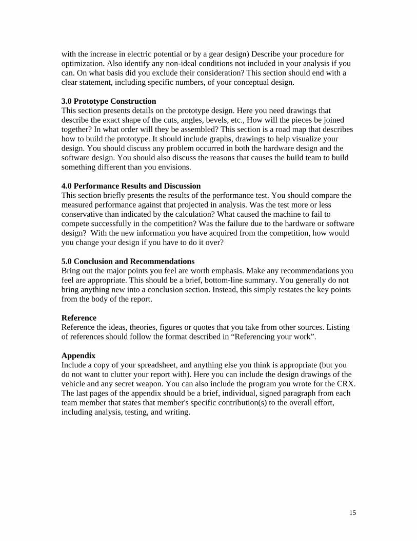
Assignment #12: Final Design Project Report
Evaluation Table
Category Possible SCORE
Report: -- -- Introduction Design Analysis 10 Prototype description 10 Performance Results and Discussion 10 Conclusion 10 Appendix and Reference 10 Grammar and Spelling 10 Graphics and plots 10 Participation 10 Turned in on time 10 TOTAL 100
16
Performance Tests:
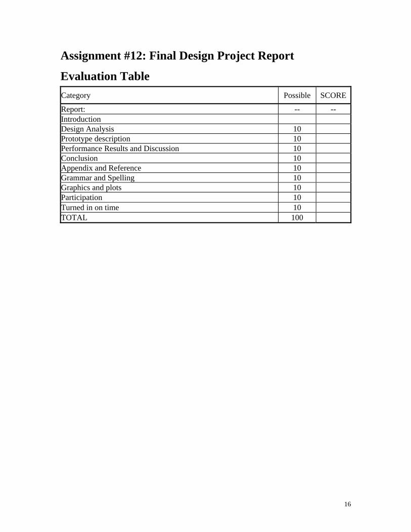
1. Optimal output power of your vehicle
We know Power = F x V,
Optimal power is located around the center point of the F Vs. V curve. The reason is that when the car is at highest weight point, the car is not moving or is moving very slowly. The resulting power is low. When the car is moving a higher speed, it is not pulling a lot weight. The resulting power is also low. So the Optimal power should occur right around the center point of the curve where you optimize both the speed and the force of your vehicle. When vehicle is operating at high force region, it usually means you have a high torque output from your drive train.
Pulley Your machine
table
Bucket filled with different weight
x , t
vlo
Flo
Higher outputPower
Fhi
Vhi
17

To generate the curve, a series of F and corresponding V need to be collected. (Min. of Five points)
- F is equal to the weight hang over the pulley - The corresponding Avg. velocity V is derived based
on the measured x and t. V= x/t
Procedure:
First use a scale and weight the bucket with a load. Then use a sufficiently long string (two times the height of the table where the pulley sits) and tie one end to the vehicle and the other to the bucket. (see Figure above) Let the car go, start measuring the time (t ) after the weight start to rise. The total distance (x) car will travel is equal to the height of the table. So the avg. velocity is equal to V = height of the table/time the weight rise from the bottom to the top of the table Repeat the same procedure for four other weights and use Excel to generate the curve. Based on the curve, find the optimal power of your vehicle.
18
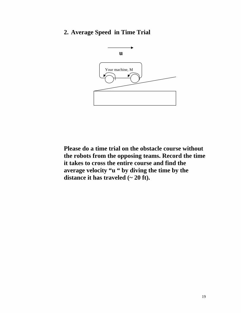
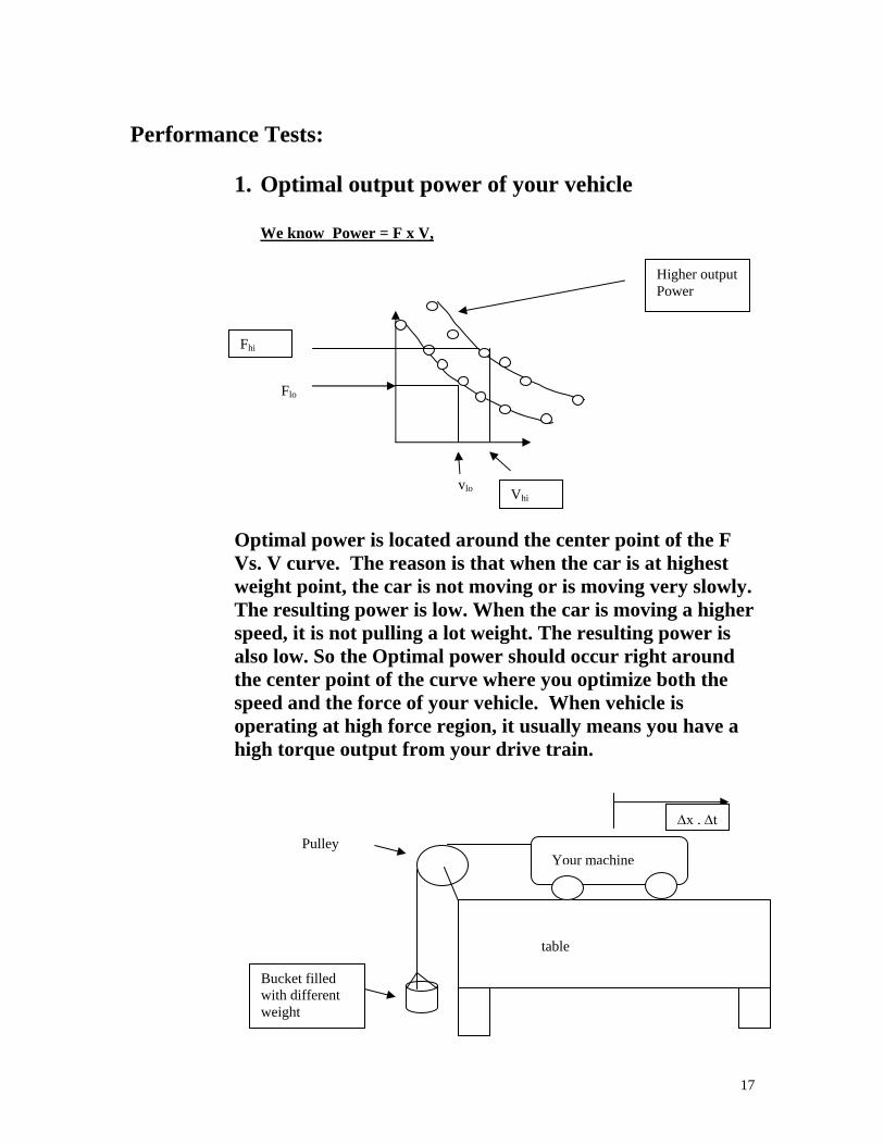
2. Average Speed in Time Trial
u Your machine, M
Please do a time trial on the obstacle course without the robots from the opposing teams. Record the time it takes to cross the entire course and find the average velocity “u “ by diving the time by the distance it has traveled (~ 20 ft).
19
Tricks and things to watch out for:
1.Version 1.5 CRX doesn’t have a AC jack. This means you can not use the AC plug to power your CRX during programming.
2.The first time your RCX is turned on, or after the batteries have been switched, your RCX is in Boot mode. You can see if your RCX is in boot mode by looking at the display window. If there is no software watch, it is.
3.In boot mode, you cannot download programs to your robot because your RCX needs firmware. Firmware is a special software that allows communication between your computer and the RCX to occur. It acts as the RCX’s operation system. Or your can call the firmware as driver program for the RCX –like assembler program convert assembly code to machine code. 4. Please check the intensity level from the floor, the printer paper (crosswalk), the wall and the wooden ramp and steps. Plus the lamp (for stopping if you are the car). 5. Light sensor intensity reading is based on the light incident to the detector. The light includes both the ambient and the reflecting light from the red LED. 6.Traffic is stopped by pushing a switch near the lamp. Cars must be programmed to be off the crosswalk when light from the lamp is on. 7. Tryout tool –testing the way an RCX code block will work with your robot. To use it, make sure your RCX is on and in range of the IR transmitter. Then click the Try-out tool and a code block in your program. Clicking command blocks sends commands directly to the RCX and causes your RCX to run that block. Clicking Sensor Watchers shows the attached sensor’s reading (i.e. how much light the light sensor sees).
8.Proximity sensor or range sensor- Detect wall, blockage, distance and velocity of the robot using ultrasonic device (i.e. polaroid camera focusing device) or displacement sensor, or
9. Gearing- Generally, the ratio of gear size determines the ratios of the resulting torques; if the output gear is larger than the input gear, then the torque increases. In addition to the change of torque, there is a corresponding change of speed. The larger gear will rotate more slowly than the smaller gear, again at a rate proportional to their radii. 10. Please read through User Guide carefully and follow the instruction and guideline for proper hardware and software installation.
Untilize the light sensor wisely.
Light Sensor spec. Use for: guiding the robot going in straight path
20

Tactile sensor Spec.
Use for: 11. Check out LEGO support groups and related web sites for design ideas and add-on sensors. Don’t constrain your design based on the given instruction menu. Try out different ideas and test them. 12. Please test your robot on the actual course at least couple time to know the course and design specification. 13. Each robot is required to be programmed for as a moving car (that stop for a wheelchair crossing the street), an unfriendly robot, and a robotic wheelchair.
Please decorate your wheelchair to make it look like a real wheelchair. If we do well, we could be on TV…
21

Components: RCX micro-computer: RCX is a programmable micro-computer. It is the brain of the robot. A wireless link to the RCX itself allows robot to sense and to move. RCX can be programmed using a PC via an IR transceiver. The RCX has three input ports for sensors (e.g. push button “ touch” sensor or light sensor) and three output ports (e.g. for motors or lights). IR transceiver: Downloading the program from your PC to RCX requires a pair of special infrared (IR) transceivers (similar to your TV remotes). One IR-transceiver is connected to a serial port of the personal computer and the other built in RCX. Communication is established via transmission/reception of infrared light. IR transmitter uses a 38kHz carrier, which is 100 times the sampling rate of the RCX (2400bps). Software: The programming language used in the Robotics System is a simple string of icon commands. The strings visually describe the response and action of the inputs and outputs of the RCX (micro-controller). The programming language is usually referred as RCX code. As you will see when you go though the training session, RCX code is a computer program environment in which graphics are used to build a program. In RCX's code, each block displayed on the screen represents instruction. You click, grab, and link graphical blocks on the computer screen. The blocks build (stack) on one another, like pieces in a puzzle, to create a program. Sensors: Light sensor -Light sensor contains a red LED (light emitting diode) and a PIN photodiode. Light reflected from the environment either due to the LED or from the background is received at the photodiode. The sensor has a 0 to 100% dynamic range. A dim room is about 10% and pointing sensor to a 75 watts incandescent lamp with shade placed some 9 ft away is about 40%. Touch Sensor - An on/off switch sensor. Motor: The DC motor is a device that converts electrical energy into mechanical energy. The motor provided has 8 different speeds and capable of going in 2 different directions (clockwise and counterclockwise) and pulsing. For more information, please refer to the following Technical Notes or search any Lego Mindstorms related web sites.
22
Technical Notes:
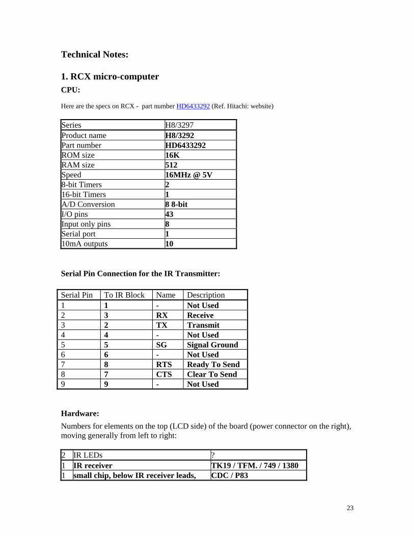
1. RCX micro-computer CPU: Here are the specs on RCX - part number HD6433292 (Ref. Hitachi: website) Series H8/3297 Product name H8/3292 Part number HD6433292 ROM size 16K RAM size 512 Speed 16MHz @ 5V 8-bit Timers 2 16-bit Timers 1 A/D Conversion 8 8-bit I/O pins 43 Input only pins 8 Serial port 1 10mA outputs 10
Serial Pin Connection for the IR Transmitter:
Serial Pin To IR Block Name Description 1 1 - Not Used 2 3 RX Receive 3 2 TX Transmit 4 4 - Not Used 5 5 SG Signal Ground 6 6 - Not Used 7 8 RTS Ready To Send 8 7 CTS Clear To Send 9 9 - Not Used
Hardware:
Numbers for elements on the top (LCD side) of the board (power connector on the right), moving generally from left to right: 2 IR LEDs ? 1 IR receiver TK19 / TFM. / 749 / 1380 1 small chip, below IR receiver leads, CDC / P83
23
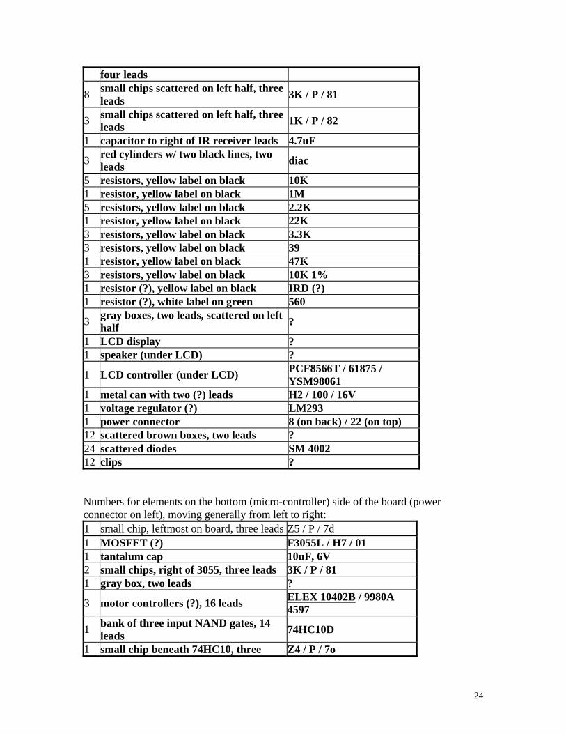
four leads
8 small chips scattered on left half, three leads
3K / P / 81
3 small chips scattered on left half, three leads
1K / P / 82
1 capacitor to right of IR receiver leads 4.7uF
3 red cylinders w/ two black lines, two leads
diac
5 resistors, yellow label on black 10K 1 resistor, yellow label on black 1M 5 resistors, yellow label on black 2.2K 1 resistor, yellow label on black 22K 3 resistors, yellow label on black 3.3K 3 resistors, yellow label on black 39 1 resistor, yellow label on black 47K 3 resistors, yellow label on black 10K 1% 1 resistor (?), yellow label on black IRD (?) 1 resistor (?), white label on green 560
3 gray boxes, two leads, scattered on left half
?
1 LCD display ? 1 speaker (under LCD) ?
1 LCD controller (under LCD) PCF8566T / 61875 / YSM98061
1 metal can with two (?) leads H2 / 100 / 16V 1 voltage regulator (?) LM293 1 power connector 8 (on back) / 22 (on top) 12 scattered brown boxes, two leads ? 24 scattered diodes SM 4002 12 clips ? Numbers for elements on the bottom (micro-controller) side of the board (power connector on left), moving generally from left to right: 1 small chip, leftmost on board, three leads Z5 / P / 7d 1 MOSFET (?) F3055L / H7 / 01 1 tantalum cap 10uF, 6V 2 small chips, right of 3055, three leads 3K / P / 81 1 gray box, two leads ?
3 motor controllers (?), 16 leads ELEX 10402B / 9980A 4597
1 bank of three input NAND gates, 14 leads
74HC10D
1 small chip beneath 74HC10, three Z4 / P / 7o
24
leads
1 small chip above right of 74HC10, three leads
1K / P / 82
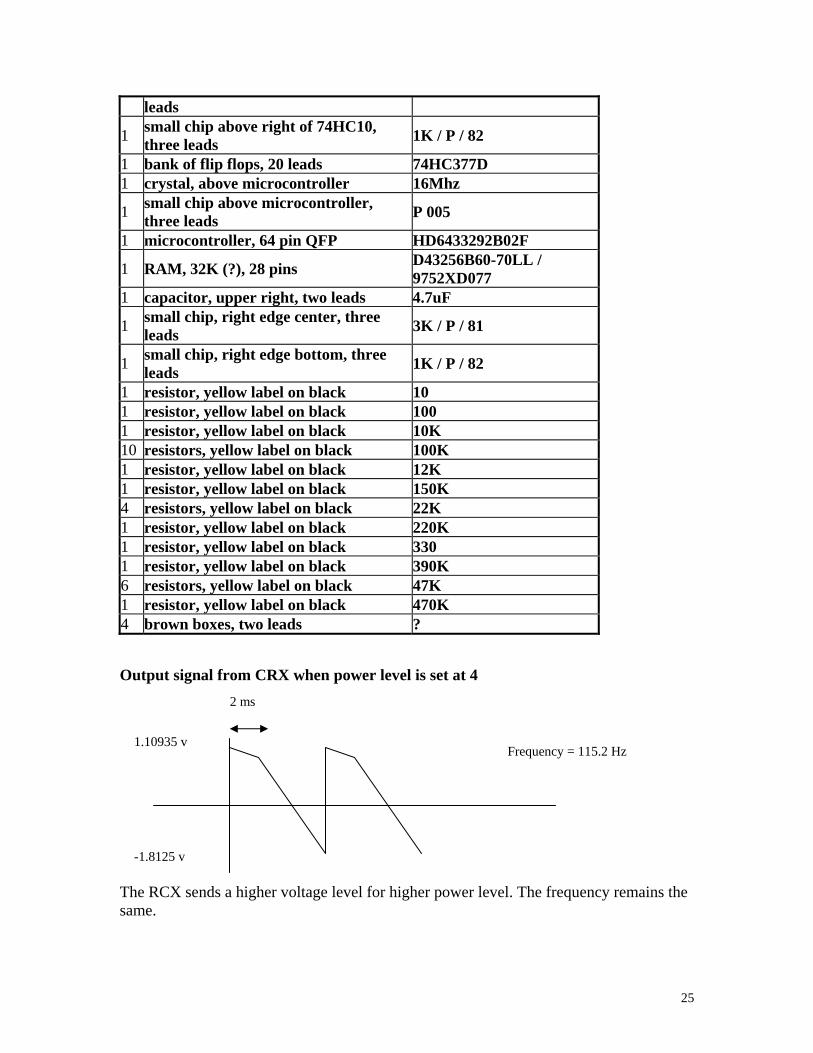
1 bank of flip flops, 20 leads 74HC377D 1 crystal, above microcontroller 16Mhz
1 small chip above microcontroller, three leads
P 005
1 microcontroller, 64 pin QFP HD6433292B02F
1 RAM, 32K (?), 28 pins D43256B60-70LL / 9752XD077
1 capacitor, upper right, two leads 4.7uF
1 small chip, right edge center, three leads
3K / P / 81
1 small chip, right edge bottom, three leads
1K / P / 82
1 resistor, yellow label on black 10 1 resistor, yellow label on black 100 1 resistor, yellow label on black 10K 10 resistors, yellow label on black 100K 1 resistor, yellow label on black 12K 1 resistor, yellow label on black 150K 4 resistors, yellow label on black 22K 1 resistor, yellow label on black 220K 1 resistor, yellow label on black 330 1 resistor, yellow label on black 390K 6 resistors, yellow label on black 47K 1 resistor, yellow label on black 470K 4 brown boxes, two leads ? Output signal from CRX when power level is set at 4
2 ms 1.10935 v
Frequency = 115.2 Hz
-1.8125 v The RCX sends a higher voltage level for higher power level. The frequency remains the same.
25
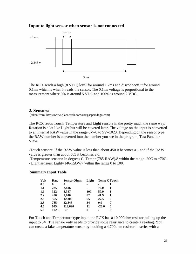
Input to light sensor when sensor is not connected
100 us
3 ms
46 mv
-2.343 v
The RCX sends a high (8 VDC) level for around 1.2ms and disconnects it for around 0.1ms which is when it reads the sensor. The 0.1ms voltage is proportional to the measurement where 0% is around 5 VDC and 100% is around 2 VDC.
2. Sensors: (taken from http://www.plazaearth.com/usr/gasperi/lego.com) The RCX reads Touch, Temperature and Light sensors in the pretty much the same way. Rotation is a lot like Light but will be covered later. The voltage on the input is converted to an internal RAW value in the range 0V=0 to 5V=1023. Depending on the sensor type, the RAW number is converted into the number you see in the program, Test Panel or View. -Touch sensors: If the RAW value is less than about 450 it becomes a 1 and if the RAW value is greater than about 565 it becomes a 0. -Temperature sensors: In degrees C, Temp=(785-RAW)/8 within the range -20C to +70C. - Light sensors: Light=146-RAW/7 within the range 0 to 100. Summary Input Table Volt Raw Sensor Ohms Light Temp C Touch 0.0 0 0 - - 1 1.1 225 2,816 - 70.0 1 1.6 322 4,587 100 57.9 1 2.2 450 7,840 82 41.9 1 2.8 565 12,309 65 27.5 0 3.8 785 32,845 34 0.0 0 4.6 945 119,620 11 -20.0 0 5.0 1023 Inf 0 - 0 For Touch and Temperature type input, the RCX has a 10,000ohm resistor pulling up the input to 5V. The sensor only needs to provide some resistance to create a reading. You can create a fake temperature sensor by hooking a 4,700ohm resistor in series with a
26
27
50,000ohm potentiometer (both available from Radio Shack). This will read from about -11C to +60C. With Touch or Temperature sensors there is no reason why you can't overdrive the input to whatever voltage you want within the 0V to 5V range. You should NOT try to overdrive an input that thinks it has a Light or Rotation Sensor type on it. Use one of the general purpose analog interfaces. The RCX has a 120ohm resistor pulling up to about 8V (probably a diode drop from the battery voltage) to power the red LED for about 3ms and then looks at the sensor voltage during a short 0.1ms time. During the short time the sensor is read just like the Touch or Temperature sensors. The fake Temperature sensor from above will read Light values from 100 down to about 22 without the risk of damaging the RCX since it never loads the input with less than 4,700ohms. I doubt any real damage would occur to the RCX since people could accidentally connect a Touch sensor where a Light sensor should be or even a motor output to a sensor input. I can't imagine LEGO would allow this to destroy the RCX, but don't say "I didn't warn you."