Embed Size (px)
Citation preview

S. Chien, S. Choo, M. A. Schnabel, W. Nakapan, M. J. Kim, S. Roudavski (eds.), Living Systems and Micro-Utopias: Towards Continuous Designing, Proceedings of the 21st International Conference of the Association for Computer-Aided Architectural Design Research in Asia CAADRIA 2016, 559–568. © 2016, The Association for Computer-Aided Architectural Design Research in Asia (CAADRIA), Hong Kong.
ROBOTIC PRODUCTION OF INDIVIDUALISED WOOD JOINTS
Fabricating an Info Point Structure for the WCTE
BARIS COKCAN1, JOHANNES BRAUMANN2, W. WINTER3 and MARTIN TRAUTZ4 1,4 RWTH Aachen University, Aachen, Germany {bcokcan, trautz}@trako.arch.rwth-aachen.de 2 Association of Robots in Architecture, Vienna, Austria [email protected] 3 TU Wien, Vienna, Austria [email protected]
Abstract. Modern modular constructions can consist of highly indi-vidualised elements that are produced at nearly the same efficiency as serial manufacturing. This paper focuses on the project “WoodWaves” an Info-Point for the conference World Congress of Timber Engineer-ing, which was designed with this new conception of modularity. The process utilises a robotically operated milling cutter to form block-board panels out of spruce, which make up the multifunctional infor-mation point. The entire object is produced with only sliding dovetail joints. Parametric design methods were developed to automatically adjust each joint to fit the individual conditions. New CAD/CAM in-terfaces, linking design directly with fabrication, enabled the serial production of 108 different shaped elements with a 6-axis robotic arm.
Keywords. Computational design; robotic production; digital fabrica-tion; wood joints; info-point.
1. Introduction
The aim of the project was to design an Info-Point for the World Conference on Timber Engineering, acting as a recognizable landmark while also pro-viding information to attendees. The design of the object should emphasise the innovation and high performance of wood-based constructions, while the temporary nature of the event required quick assembly and disassembly, the

560 B.COKCAN, J.BRAUMANN, W.WINTER AND M.TRAUTZ
reusability of elements and versatile usage of the space. Wooden blockboard was provided by a commercial partner and incorporated as an important de-sign parameter from the beginning.
We started a student competition at the department of Timber Engineer-ing to find a design that would represent the university. 17 students took part, resulting in a total of 12 projects. After a 5-week planning period the project “WoodWaves” was selected by the jury for realisation (Figure 1). The project was chosen due its flexibility in design and the feasibility of a digital production process. Due to the fact that all single elements had a unique shape, a computer aided manufacturing machine would be required. By engraving information into the wood, the winning project was able to in-corporate the WCTE-relevant information as part of the elements without adding additional information devices such as flatscreens.
Figure 1. Initial WoodWaves concept model (left), final WoodWaves structure with engraved
information (right).
2. Design idea and process
The fluent design of the multifunctional Info-Point leads to its unique ap-pearance. Its shape is defined by two different curves, which overlap asym-metrically. The main curve defines the information panels while the other curve defines the table and bench. Only these initial curves are sketched by the designer within the CAD environment Rhinoceros - the resulting form, location and size of panels are then automatically defined through generative design methods in the second step, e.g. shaping the doubly curved edges of the panels using two sinusoids. While the panels are placed nearly parallel to each other, their spacing gradually varies.

ROBOTIC PRODUCTION OF INDIVIDUALISED WOOD JOINTS 561
3. Detailing & materialising
Our goal was to be able to set up the object with tight fitting joints to avoid using any screws or glue, so that it can be assembled and disassembled mul-tiple times over its lifespan. In the initial design the main panels were fixed at three points with smaller elements (Figure 1, left). The disadvantage of this solution was the high amount of joining elements and having to produce individual grooves in the main panels. A further disadvantage of multiple joints was a reduction in space available for the information area within the main panels plus a lack of stability in the overall structure.
The subsequent design added a second layer of panels of lower height (41-75 cm) with free formed edges to the main panels to stabilise lower structure. Orthogonally to the direction of the main structure a second curved row of elements with the same construction principle as described above was added to stabilise the overall structure.
The detail for the panel connections was developed as a variation of the “sliding dovetail” woodworking joint. Usually, the sliding dovetail is a method of joining two boards at right angles. However, due to the non-rectangular arrangement of panels, the joints had to be generated dynamical-ly in order to realise the given shape. Thus, each and every single tail is de-signed and produced with a different angle (placed on the small connection panels). The slightly tapered sockets are designed with a right angle and are located on both sides of the main panels (Figure 2).
Figure 2. Sliding Dovetail: Initial concept model (left), final fabricated elements (right).
The entire object uses a single type of blockboard with 5 layers, called “BACO MDF Triple Core” (Spruce), and produced by Schweighofer. In or-

562 B.COKCAN, J.BRAUMANN, W.WINTER AND M.TRAUTZ
der to be able to mill the socket on both sides of the panel, the required thickness of the panel was calculated to be 34 mm. While the 3 inner layers consist of spruce, the outer layers are covered with 2mm MDF panels.
4. Implementation
The final model of the Info-Point required 108 individually-shaped parts. 21 main panels define the appearance of the object and are engraved with brief information about the WCTE conference. A further 13 panels with a length of 450 mm form a bench and 8 panel with a length of 1100 mm form a bar table. The remaining 66 plates are connection elements.
4.1. DIGITAL DATA
While the general, global shape of the structure is relatively easy to generate, actually fabricating the structure required a much more precise detailing. In collaboration with the wood-engineers we developed a construction logic that would allow us to easily assemble and disassemble the entire structure, while also keeping close to the original design-intent. This construction logic was then implemented using Grasshopper, a [modular] visual programming environment (Davis et al, 2011).
Commonly, CAM software such as HyperMill would be used for prepar-ing the milling data for each panel. However, this proved to be impractical due to the large number of elements that had to be processed, with every panel having its own, unique geometry. While current CAM software is op-timised to deal with a certain amount of variable parameters, such as varying whole diameters, the complex, changing shapes of the panels would have re-quired a manual setup of each individual component.
So rather than relying on preexisting fabrication strategies in commercial CAM software, we created a new, parametric definition within Grasshopper that would allow us to fabricate each panel, simply by referencing the main geometric features such as edge curves. Since every panel is topologically similar, this enabled us to perform the more complex milling strategies for the connection elements, as well as the engraving of the information layer, within a single workflow. However, after the initial definition of the fabrica-tion strategy, the entire fabrication had to be adapted to the local fabrication setup. Due to the complexity of the geometry, we had to use a milling ma-chine with at least five axes, as only that amount of kinematic flexibility would allow us to fabricate the non-vertical edges of each element. Howev-er, as five-axis CNC machines with a sufficiently large workspace are very rare, we instead decided to use a six-axis robot that was set up with the ex-plicit goal of being used for wood fabrication.

ROBOTIC PRODUCTION OF INDIVIDUALISED WOOD JOINTS 563
While a six-axis robot provides even greater kinematic flexibility than the previously mentioned CNC machines, we had to carefully consider the workspace of the machine. Unlike CNC machines that are commonly built “around” the workpiece, the robot stands within its own workspace, making an accurate prediction of reachability difficult.
Figure 3. Checking the reachability of the KUKA robot with KUKA|prc - the axis movement of the robot is graphed in a separate window (above). Physical fabrication with challenging
shallow angles (below).
Rather than experimenting on-site, we decided to use KUKA|prc (para-metric robot control) – an accessible software tool that allows the user to control industrial robots from within the visual programming environment (Brell-Cokcan, Braumann, 2010). Coupling KUKA|prc with the existing parametric toolpath definition allowed us to immediately check every panel for reachability and to adjust it accordingly (Figure 3, top).
564 B.COKCAN, J.BRAUMANN, W.WINTER AND M.TRAUTZ
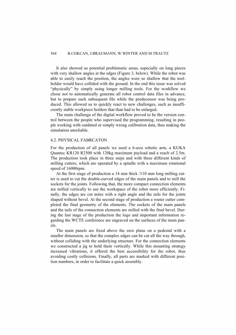
It also showed us potential problematic areas, especially on long pieces with very shallow angles at the edges (Figure 3, below). While the robot was able to easily reach the position, the angles were so shallow that the tool-holder would have collided with the ground. In the end this issue was solved “physically” by simply using longer milling tools. For the workflow we chose not to automatically generate all robot control data files in advance, but to prepare each subsequent file while the predecessor was being pro-duced. This allowed us to quickly react to new challenges, such as insuffi-ciently stable workpiece holders that than had to be enlarged.
The main challenge of the digital workflow proved to be the version con-trol between the people who supervised the programming, resulting in peo-ple working with outdated or simply wrong calibration data, thus making the simulation unreliable.
4.2. PHYSICAL FABRCATON
For the production of all panels we used a 6-axis robotic arm, a KUKA Quantec KR120 R2500 with 120kg maximum payload and a reach of 2.5m. The production took place in three steps and with three different kinds of milling cutters, which are operated by a spindle with a maximum rotational speed of 16000rpm.
At the first stage of production a 14 mm thick /110 mm long milling cut-ter is used to cut the double-curved edges of the main panels and to mill the sockets for the joints. Following that, the more compact connection elements are milled vertically to use the workspace of the robot more efficiently. Fi-nally, the edges are cut mitre with a right angle and the tails for the joints shaped without bevel. At the second stage of production a router cutter com-pleted the final geometry of the elements. The sockets of the main panels and the tails of the connection elements are milled with the final bevel. Dur-ing the last stage of the production the logo and important information re-garding the WCTE conference are engraved on the surfaces of the main pan-els.
The main panels are fixed above the zero plane on a pedestal with a smaller dimension, so that the complex edges can be cut all the way through, without colliding with the underlying structure. For the connection elements we constructed a jig to hold them vertically. While this mounting strategy increased vibrations, it offered the best accessibility for the robot, thus avoiding costly collisions. Finally, all parts are marked with different posi-tion numbers, in order to facilitate a quick assembly.
ROBOTIC PRODUCTION OF INDIVIDUALISED WOOD JOINTS 565
4.3. CHALLENGES
In order to interlock the parts smoothly, the sockets and the tails for the con-nections have been designed and produced with a tolerance of 0.5 mm. De-spite this tolerance we realised that the sockets and the tails did not fit pre-cisely after the production process. We measured a deviation along the longitudinal edge of the tails up to 1 mm.
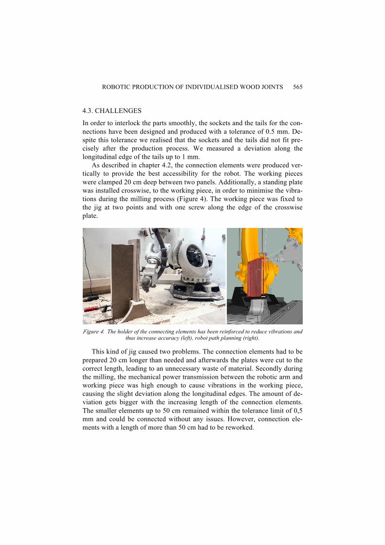
As described in chapter 4.2, the connection elements were produced ver-tically to provide the best accessibility for the robot. The working pieces were clamped 20 cm deep between two panels. Additionally, a standing plate was installed crosswise, to the working piece, in order to minimise the vibra-tions during the milling process (Figure 4). The working piece was fixed to the jig at two points and with one screw along the edge of the crosswise plate.
Figure 4. The holder of the connecting elements has been reinforced to reduce vibrations and
thus increase accuracy (left), robot path planning (right).
This kind of jig caused two problems. The connection elements had to be prepared 20 cm longer than needed and afterwards the plates were cut to the correct length, leading to an unnecessary waste of material. Secondly during the milling, the mechanical power transmission between the robotic arm and working piece was high enough to cause vibrations in the working piece, causing the slight deviation along the longitudinal edges. The amount of de-viation gets bigger with the increasing length of the connection elements. The smaller elements up to 50 cm remained within the tolerance limit of 0,5 mm and could be connected without any issues. However, connection ele-ments with a length of more than 50 cm had to be reworked.

566 B.COKCAN, J.BRAUMANN, W.WINTER AND M.TRAUTZ
This vibration problem did not affect the production process of the main panels as the working pieces were milled on top of a large support. All sock-ets were produced without appreciable deviation along longitudinal edges.
4.4. ASSEMBLY
Every single element was checked against its neighbors while still at the woodshop, sanding each tail and socket. Each main panel was placed hori-zontally so that the connecting elements could be easily pushed into its sock-ets. Afterwards the partially assembled elements were repositioned vertical-ly. This process was repeated for each group (main panel plus connection elements), sequentially combining those into a single object (Figure 5). Three people assembled the whole object within 90 minutes.
Figure 5. Final, assembled WoodWaves Info Point.
5. Related work
Since 2010 several experimental projects with wooden joints were realised using industrial robots. Some of them were developed and realised by Menges, Schwinn and Robeller. They use dovetail and finger joints for wood to wood connection. The robotic fabrication allows for the efficient fabrica-tion of performative finger joint connections even at extreme angles.
In the project of Menges and Schwinn the contact surface of the pins and tails are arranged orthogonally to the edge. (Schwinn et al, 2012). Robeller’s dovetail joint tails and pins were milled with a fold angle of 167,2° (Robeller et al, 2014).
In a common dovetail joint many pins and tails run alternately along the edges, while with a sliding dovetail joint – as in the WoodWaves project -

ROBOTIC PRODUCTION OF INDIVIDUALISED WOOD JOINTS 567
there is just one socket and tail. The socket runs along the surface and the tail is placed on along the edge (Figure 6).
Figure 6 Assembling of the panels and joint detail (left), connection elements with different
angles by the edges (right)
The stability of this type of connection depends heavily on the precise and congruous production of the socket and tails. Due to the organic form of the object all panels are connected with different angles, which vary from 26,7° to 66,5° (Figure 6). The sockets and tails are formed as if they were a common right angle connection, but the tails are connected to the edges at varying angle. Using this methodology even extreme angles can be produced without breaking edges.
Industry commonly uses 5 axis joinery machines for dovetail joints. However, these machines are very voluminous and expensive, so that only large wood fabricators specialised in mass production can afford them. The most frequent industrial use for dovetail joints are beam to beam connec-tions, which can be produced by joinery machines with different angles.
Thus, joinery machines are optimised for the manufacturing methodology of the carpenter, so that standard applications can be programmed rather eas-ily and are then performed with great speed and accuracy. Problems only arise once nonstandard solutions are required. The programming difficult geometry is time consuming and not as flexible as with a robot arm. While robots – due to their kinematic layout – cannot compete with specialised ma-chines in regards to total accuracy and speed, these machines represent a new an affordable way towards making complex joinery technologies avail-able to smaller companies and even individual carpenters, that were previ-ously only accessible to high-end industry.
6. Conclusion
The results of this project represent the first step of investigation for a re-search program, which compares digital fabrication techniques with common
568 B.COKCAN, J.BRAUMANN, W.WINTER AND M.TRAUTZ
carpenter production methods. Instead of having to rely on mass-fabricated elements, today’s digital and mechanic tools allow us to create designs that consist of individualised building parts. However, to cope with the com-plexity of the high number of digital shapes, it is not sufficient to solely draw a 2D plan or even a 3D model. Instead, contemporary architectural design methods require the use of digital parametric design tools and knowledge of programming (Agkathidis, 2009).
Combining such high-end digital processes with the high-end, ecological material wood can now create new, sustainable designs with the same effi-ciency as mass-production.
New interfaces enable a direct communication between 3D modelling software and complex machines such as robotic arms. This allows designers and architects to develop entire manufacturing methods by themselves, and gives them to control over all aspects of a design, from sketch to fabrication (Brell-Cokcan and Braumann, 2012).
Acknowledgements WoodWaves was realised within the research project “Robotic Woodcraft”, funded through the FWFs program for arts-based research. The project management is headed by the Depart-ment of Architectural Sciences Structural Design and Timber Engineering by Prof. Wolfgang Winter and Barış Çokcan. The RIA contributed the parametric models and the robot pro-gramming. The production took place at the Department for Wood Technology (Reinhold Krobath with Philipp Hornung and Georg Sampl of the University of Applied Arts, Vienna.
References Agkathidis, A.: 2009, Modulare Strukturen, in Architektur und Entwerfen, 47–50. Brell-Cokcan, S. and Braumann, J.: 2010, A New Parametric Design Tool for Robot Milling.
ACADIA 2010: LIFE in:formation Proceedings. Brell-Cokcan, S. and Braumann, J. (eds.): 2012, Robotic Fabrication in Architecture Art and
Design, Springer Wien. Buri, H. and Weinand, Y.: 2012, Tektonik der Holzarchitektur im digitalen Zeitalter - Bauen
mit Holz Wege in die Zukunft, 56–63. Davis, D., Burry M., and Burry J.: 2011 Untangling Parametric Schemata: Enhancing Collab-
oration through Modular Programming, CAADRIA 2011 Proceedings. Ludwig, M.: 1998, Mobile Architektur. Robeller, C., Nabaei, S., and Weinand, Y.: 2014, Design and Fabrication of Robot-
Manufactured Joints for a Curved-Folded Thin-Shell Structure Made from CLT, in W. McGee and M. Ponce de Leon (eds.) Robotic Fabrication in Architecture, Art and Design 2014, Springer Wien, 67–81
Schroeder, S.: 1990, Holzrahmenkonstruktionen, Werner Verlag, Düsseldorf. Schwinn, T., Krieg, O., and Menges, A.: 2012, Robotically Fabricated Wood Plate Morphol-
ogies in S. Brell-Cokcan and J. Braumann (eds.), Robotic Fabrication in Architecture Art and Design, Springer Wien, 48–61