Embed Size (px)
Citation preview
Robotic Folding of 2D and 3D Structures from a Ribbon
Liyu Wang, Mark M. Plecnik, and Ronald S. Fearing
Abstract— Automatic folding has drawn increasing attentionin robotics research in the past ten years. The focus has been onfolding two-dimensional (2D) sheets into three-dimensional (3D)structures, but little work has been done on how structures maybe formed by folding ribbons. Here we propose the concept ofrobotic ribbon folding including a general workflow from shapedesign to ribbon folding and shape retention. We also proposea method to realize robotic ribbon folding on the macroscopicscale. The method consists of minimally engineered ribbons withpatterned flexures, a folding robot, and a folding scheme thatrelates the orientation of flexures, the type of folds and the typeof structural elements. By using this method we demonstraterobotic ribbon folding into 2D static structures such as trianglesand squares, 3D static structures, and planar kinematic linkagessuch as a simple non-crossing four-bar mechanism. Burn-inresult shows a four-bar mechanism with all bars’ length of 5cm could move repeatedly for at least half an hour.
I. INTRODUCTION
Folding has been studied in the field of robotics andautomation for over twenty years. Early work used manually-folded structures to build e.g. joints in the exoskeleton for aninsect-like robot [1], a gripper [2], the thorax and wing fora flying robot [3]. Folded structures have the advantage oflight weight and low friction in systems on the micrometeror millimeter scale. Folding can also be good for formingabstract macroscopic structures because it is faster and ituses relatively less material than conventional subtractive oradditive techniques.
Studies on automatic folding focus on folding from a2D sheet to 3D structures where the thickness of the sheetis negligible. They have been physically demonstrated intwo categories and are sometimes associated with the art oforigami. The first category is robotic sheet folding, where arobot is programmed to sequentially fold a piece of cardboardor paper into a structure [4], [5]. The second categoryis self-folding structures and robots [6], [7], [8]. Thesestructures or robots are sheets of highly-engineered materialwith patterned flexures. During folding, embedded actuatorsor stored energy cause the sheet to bend simultaneously atall flexures. One such sheet of material may self-fold intomultiple structures depending on the activation of flexures.
In nature structure formation based on sheet folding existsin plants, but the most fundamental process of protein foldingtakes a different form i.e. folding from a long and thinpiece. In many organisms, a protein’s biological function isdetermined by its 3D native structure, which is physically
*This work was supported by Swiss National Science Foundation EarlyPostdoc Mobility Fellowship
All authors are with the Department of Electrical Engineering andComputer Sciences, University of California, Berkeley, 94720 CA, [email protected]
(a)
(b)
Ribbon folded 3D structure
Fig. 1. Robotic ribbon folding. (a) A 3D structure with two intersectedplanes folded from a minimally engineered ribbon by a machine. The ribbonis minimally engineered from paperboard. (b) Sketch design of the machinethat folds the minimally engineered ribbon. The machine has a feedingmotor and two folding motors.
folded from a linear string of amino acid monomers [9].Given the biological evidence, ribbon or string folding mayrepresent a more general method than sheet folding forforming structures [10], that is the set of possible structuresmay be larger. When used as a robotics and automation tech-nology, it may be a simple and compact method to performlow-cost prototyping or on-the-fly structure generation, etc.
Automatic folding of a ribbon or a string has not beenthoroughly investigated for the purpose of automatic struc-ture formation. On the algorithm and design side, Cheung etal. formulated an algorithm for constructing the Hamiltonianpath for an arbitrary structure as the sufficient condition forthe structure being foldable from a string [10]; Risi et al. usedcomputational optimization techniques to find the optimalribbon-folded structure for a locomotion task in simulation[11]. On the physical implementation side, Shechter et al.introduced a self-assembly method to build 3D microstruc-tures from a number of serially connected microfabricatedpanels with embedded magnets [12]. White et al. proposed
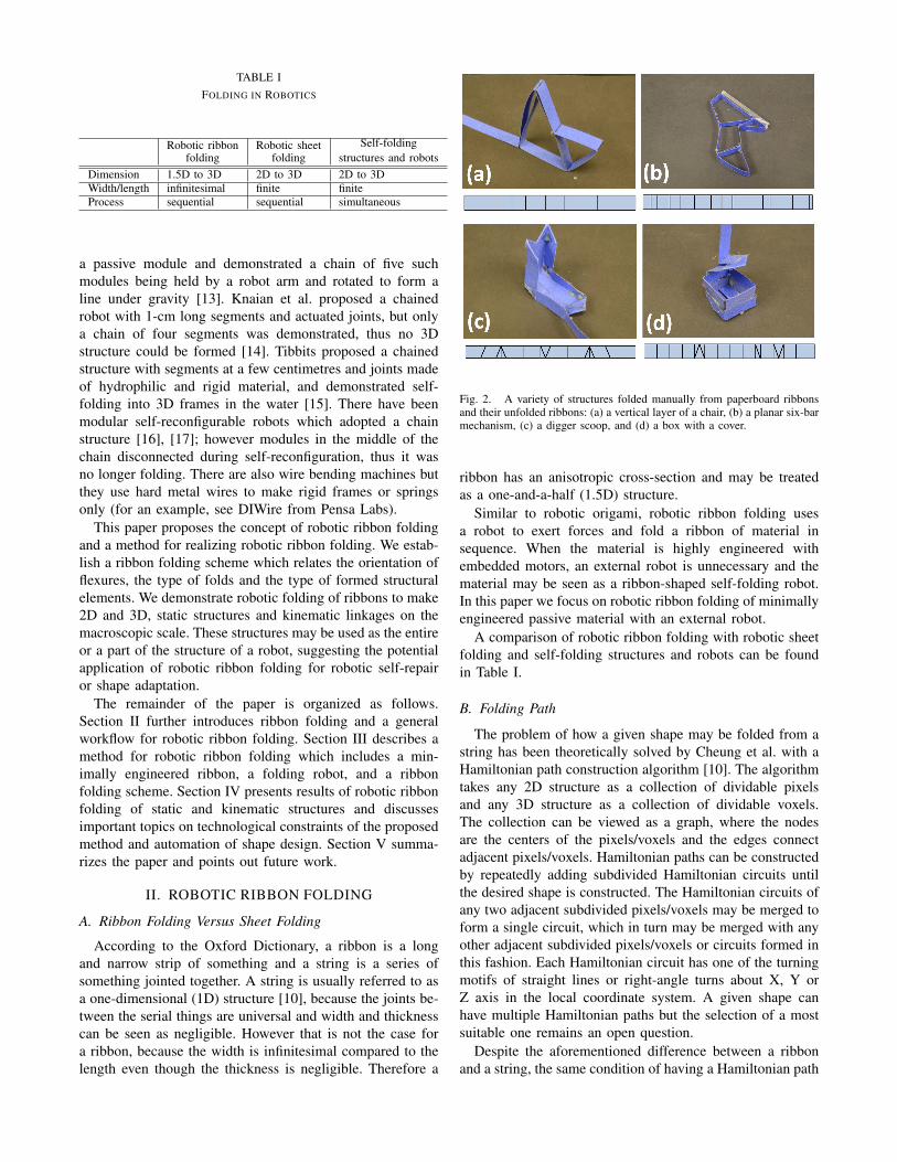
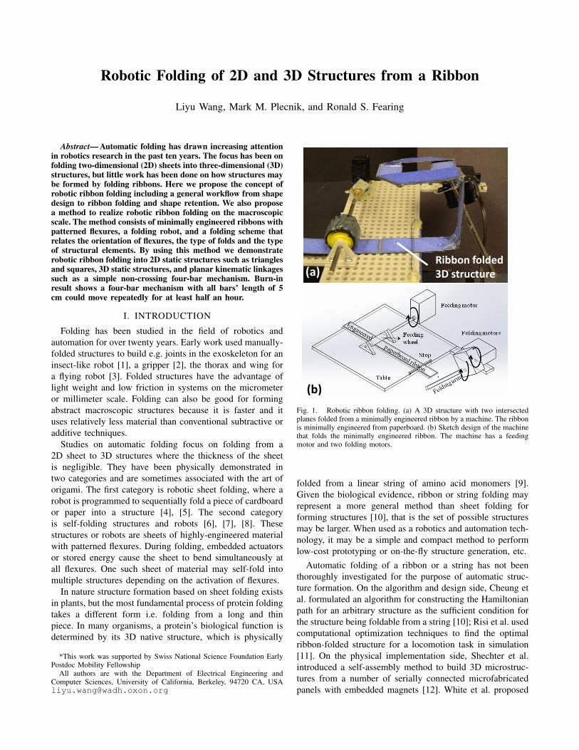
TABLE IFOLDING IN ROBOTICS
Robotic ribbonfolding
Robotic sheetfolding
Self-foldingstructures and robots
Dimension 1.5D to 3D 2D to 3D 2D to 3DWidth/length infinitesimal finite finiteProcess sequential sequential simultaneous
a passive module and demonstrated a chain of five suchmodules being held by a robot arm and rotated to form aline under gravity [13]. Knaian et al. proposed a chainedrobot with 1-cm long segments and actuated joints, but onlya chain of four segments was demonstrated, thus no 3Dstructure could be formed [14]. Tibbits proposed a chainedstructure with segments at a few centimetres and joints madeof hydrophilic and rigid material, and demonstrated self-folding into 3D frames in the water [15]. There have beenmodular self-reconfigurable robots which adopted a chainstructure [16], [17]; however modules in the middle of thechain disconnected during self-reconfiguration, thus it wasno longer folding. There are also wire bending machines butthey use hard metal wires to make rigid frames or springsonly (for an example, see DIWire from Pensa Labs).
This paper proposes the concept of robotic ribbon foldingand a method for realizing robotic ribbon folding. We estab-lish a ribbon folding scheme which relates the orientation offlexures, the type of folds and the type of formed structuralelements. We demonstrate robotic folding of ribbons to make2D and 3D, static structures and kinematic linkages on themacroscopic scale. These structures may be used as the entireor a part of the structure of a robot, suggesting the potentialapplication of robotic ribbon folding for robotic self-repairor shape adaptation.
The remainder of the paper is organized as follows.Section II further introduces ribbon folding and a generalworkflow for robotic ribbon folding. Section III describes amethod for robotic ribbon folding which includes a min-imally engineered ribbon, a folding robot, and a ribbonfolding scheme. Section IV presents results of robotic ribbonfolding of static and kinematic structures and discussesimportant topics on technological constraints of the proposedmethod and automation of shape design. Section V summa-rizes the paper and points out future work.
II. ROBOTIC RIBBON FOLDING
A. Ribbon Folding Versus Sheet Folding
According to the Oxford Dictionary, a ribbon is a longand narrow strip of something and a string is a series ofsomething jointed together. A string is usually referred to asa one-dimensional (1D) structure [10], because the joints be-tween the serial things are universal and width and thicknesscan be seen as negligible. However that is not the case fora ribbon, because the width is infinitesimal compared to thelength even though the thickness is negligible. Therefore a
Fig. 2. A variety of structures folded manually from paperboard ribbonsand their unfolded ribbons: (a) a vertical layer of a chair, (b) a planar six-barmechanism, (c) a digger scoop, and (d) a box with a cover.
ribbon has an anisotropic cross-section and may be treatedas a one-and-a-half (1.5D) structure.
Similar to robotic origami, robotic ribbon folding usesa robot to exert forces and fold a ribbon of material insequence. When the material is highly engineered withembedded motors, an external robot is unnecessary and thematerial may be seen as a ribbon-shaped self-folding robot.In this paper we focus on robotic ribbon folding of minimallyengineered passive material with an external robot.
A comparison of robotic ribbon folding with robotic sheetfolding and self-folding structures and robots can be foundin Table I.
B. Folding Path
The problem of how a given shape may be folded from astring has been theoretically solved by Cheung et al. with aHamiltonian path construction algorithm [10]. The algorithmtakes any 2D structure as a collection of dividable pixelsand any 3D structure as a collection of dividable voxels.The collection can be viewed as a graph, where the nodesare the centers of the pixels/voxels and the edges connectadjacent pixels/voxels. Hamiltonian paths can be constructedby repeatedly adding subdivided Hamiltonian circuits untilthe desired shape is constructed. The Hamiltonian circuits ofany two adjacent subdivided pixels/voxels may be merged toform a single circuit, which in turn may be merged with anyother adjacent subdivided pixels/voxels or circuits formed inthis fashion. Each Hamiltonian circuit has one of the turningmotifs of straight lines or right-angle turns about X, Y orZ axis in the local coordinate system. A given shape canhave multiple Hamiltonian paths but the selection of a mostsuitable one remains an open question.
Despite the aforementioned difference between a ribbonand a string, the same condition of having a Hamiltonian path
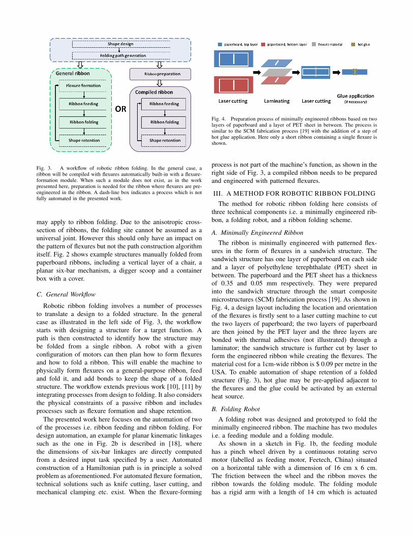
Fig. 3. A workflow of robotic ribbon folding. In the general case, aribbon will be compiled with flexures automatically built-in with a flexure-formation module. When such a module does not exist, as in the workpresented here, preparation is needed for the ribbon where flexures are pre-engineered in the ribbon. A dash-line box indicates a process which is notfully automated in the presented work.
may apply to ribbon folding. Due to the anisotropic cross-section of ribbons, the folding site cannot be assumed as auniversal joint. However this should only have an impact onthe pattern of flexures but not the path construction algorithmitself. Fig. 2 shows example structures manually folded frompaperboard ribbons, including a vertical layer of a chair, aplanar six-bar mechanism, a digger scoop and a containerbox with a cover.
C. General Workflow
Robotic ribbon folding involves a number of processesto translate a design to a folded structure. In the generalcase as illustrated in the left side of Fig. 3, the workflowstarts with designing a structure for a target function. Apath is then constructed to identify how the structure maybe folded from a single ribbon. A robot with a givenconfiguration of motors can then plan how to form flexuresand how to fold a ribbon. This will enable the machine tophysically form flexures on a general-purpose ribbon, feedand fold it, and add bonds to keep the shape of a foldedstructure. The workflow extends previous work [10], [11] byintegrating processes from design to folding. It also considersthe physical constraints of a passive ribbon and includesprocesses such as flexure formation and shape retention.
The presented work here focuses on the automation of twoof the processes i.e. ribbon feeding and ribbon folding. Fordesign automation, an example for planar kinematic linkagessuch as the one in Fig. 2b is described in [18], wherethe dimensions of six-bar linkages are directly computedfrom a desired input task specified by a user. Automatedconstruction of a Hamiltonian path is in principle a solvedproblem as aforementioned. For automated flexure formation,technical solutions such as knife cutting, laser cutting, andmechanical clamping etc. exist. When the flexure-forming
Fig. 4. Preparation process of minimally engineered ribbons based on twolayers of paperboard and a layer of PET sheet in between. The process issimilar to the SCM fabrication process [19] with the addition of a step ofhot glue application. Here only a short ribbon containing a single flexure isshown.
process is not part of the machine’s function, as shown in theright side of Fig. 3, a compiled ribbon needs to be preparedand engineered with patterned flexures.
III. A METHOD FOR ROBOTIC RIBBON FOLDING
The method for robotic ribbon folding here consists ofthree technical components i.e. a minimally engineered rib-bon, a folding robot, and a ribbon folding scheme.
A. Minimally Engineered Ribbon
The ribbon is minimally engineered with patterned flex-ures in the form of flexures in a sandwich structure. Thesandwich structure has one layer of paperboard on each sideand a layer of polyethylene terephthalate (PET) sheet inbetween. The paperboard and the PET sheet has a thicknessof 0.35 and 0.05 mm respectively. They were preparedinto the sandwich structure through the smart compositemicrostructures (SCM) fabrication process [19]. As shown inFig. 4, a design layout including the location and orientationof the flexures is firstly sent to a laser cutting machine to cutthe two layers of paperboard; the two layers of paperboardare then joined by the PET layer and the three layers arebonded with thermal adhesives (not illustrated) through alaminator; the sandwich structure is further cut by laser toform the engineered ribbon while creating the flexures. Thematerial cost for a 1cm-wide ribbon is $ 0.09 per metre in theUSA. To enable automation of shape retention of a foldedstructure (Fig. 3), hot glue may be pre-applied adjacent tothe flexures and the glue could be activated by an externalheat source.
B. Folding Robot
A folding robot was designed and prototyped to fold theminimally engineered ribbon. The machine has two modulesi.e. a feeding module and a folding module.
As shown in a sketch in Fig. 1b, the feeding modulehas a pinch wheel driven by a continuous rotating servomotor (labelled as feeding motor, Feetech, China) situatedon a horizontal table with a dimension of 16 cm x 6 cm.The friction between the wheel and the ribbon moves theribbon towards the folding module. The folding modulehas a rigid arm with a length of 14 cm which is actuated
Type of flexures Type of folds Type of structural elements
upwards (0~180º) rigid joint
with hot glue
downwards (0~-180º) rigid joint
with hot glue
none hinge joint
left 90º lap joint with hot glue
none hinge joint
right 90º lap joint
with hot glue
none hinge joint
ribbon head none T-shaped joint
with hot glue
90º
45º
-45º
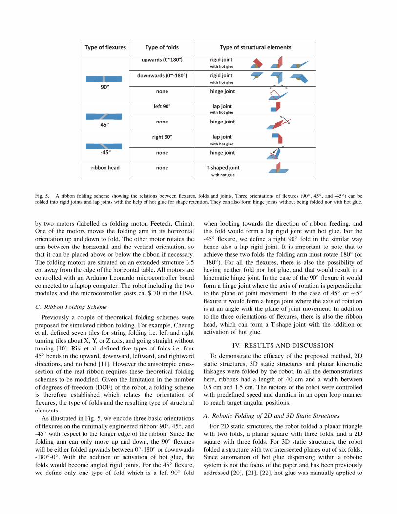
Fig. 5. A ribbon folding scheme showing the relations between flexures, folds and joints. Three orientations of flexures (90◦, 45◦, and -45◦) can befolded into rigid joints and lap joints with the help of hot glue for shape retention. They can also form hinge joints without being folded nor with hot glue.
by two motors (labelled as folding motor, Feetech, China).One of the motors moves the folding arm in its horizontalorientation up and down to fold. The other motor rotates thearm between the horizontal and the vertical orientation, sothat it can be placed above or below the ribbon if necessary.The folding motors are situated on an extended structure 3.5cm away from the edge of the horizontal table. All motors arecontrolled with an Arduino Leonardo microcontroller boardconnected to a laptop computer. The robot including the twomodules and the microcontroller costs ca. $ 70 in the USA.
C. Ribbon Folding Scheme
Previously a couple of theoretical folding schemes wereproposed for simulated ribbon folding. For example, Cheunget al. defined seven tiles for string folding i.e. left and rightturning tiles about X, Y, or Z axis, and going straight withoutturning [10]; Risi et al. defined five types of folds i.e. four45◦ bends in the upward, downward, leftward, and rightwarddirections, and no bend [11]. However the anisotropic cross-section of the real ribbon requires these theoretical foldingschemes to be modified. Given the limitation in the numberof degrees-of-freedom (DOF) of the robot, a folding schemeis therefore established which relates the orientation offlexures, the type of folds and the resulting type of structuralelements.
As illustrated in Fig. 5, we encode three basic orientationsof flexures on the minimally engineered ribbon: 90◦, 45◦, and-45◦ with respect to the longer edge of the ribbon. Since thefolding arm can only move up and down, the 90◦ flexureswill be either folded upwards between 0◦-180◦ or downwards-180◦-0◦. With the addition or activation of hot glue, thefolds would become angled rigid joints. For the 45◦ flexure,we define only one type of fold which is a left 90◦ fold
when looking towards the direction of ribbon feeding, andthis fold would form a lap rigid joint with hot glue. For the-45◦ flexure, we define a right 90◦ fold in the similar wayhence also a lap rigid joint. It is important to note that toachieve these two folds the folding arm must rotate 180◦ (or-180◦). For all the flexures, there is also the possibility ofhaving neither fold nor hot glue, and that would result in akinematic hinge joint. In the case of the 90◦ flexure it wouldform a hinge joint where the axis of rotation is perpendicularto the plane of joint movement. In the case of 45◦ or -45◦
flexure it would form a hinge joint where the axis of rotationis at an angle with the plane of joint movement. In additionto the three orientations of flexures, there is also the ribbonhead, which can form a T-shape joint with the addition oractivation of hot glue.
IV. RESULTS AND DISCUSSION
To demonstrate the efficacy of the proposed method, 2Dstatic structures, 3D static structures and planar kinematiclinkages were folded by the robot. In all the demonstrationshere, ribbons had a length of 40 cm and a width between0.5 cm and 1.5 cm. The motors of the robot were controlledwith predefined speed and duration in an open loop mannerto reach target angular positions.
A. Robotic Folding of 2D and 3D Static Structures
For 2D static structures, the robot folded a planar trianglewith two folds, a planar square with three folds, and a 2Dsquare with three folds. For 3D static structures, the robotfolded a structure with two intersected planes out of six folds.Since automation of hot glue dispensing within a roboticsystem is not the focus of the paper and has been previouslyaddressed [20], [21], [22], hot glue was manually applied to
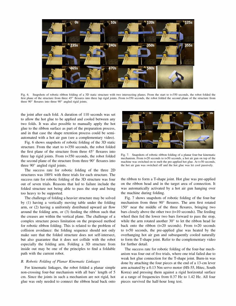
Fig. 6. Snapshots of robotic ribbon folding of a 3D static structure with two intersecting planes. From the start to t=350 seconds, the robot folded thefirst plane of the structure from three 45◦ flexures into three lap rigid joints. From t=350 seconds, the robot folded the second plane of the structure fromthree 90◦ flexures into three 90◦ angled rigid joints.
the joint after each fold. A duration of 110 seconds was setto allow the hot glue to be applied and cooled between anytwo folds. It was also possible to manually apply the hotglue to the ribbon surface as part of the preparation process,and in that case the shape retention process could be semi-automated with a hot air gun (see a complementary video).
Fig. 6 shows snapshots of robotic folding of the 3D staticstructure. From the start to t=350 seconds, the robot foldedthe first plane of the structure from three 45◦ flexures intothree lap rigid joints. From t=350 seconds, the robot foldedthe second plane of the structure from three 90◦ flexures intothree 90◦ angled rigid joints.
The success rate for robotic folding of the three 2Dstructures was 100% with three trials for each structure. Thesuccess rate for robotic folding of the 3D structure was fourout of seven trials. Reasons that led to failure include thefolded structure not being able to pass the stop and beingtoo heavy to be supported.
The challenge of folding a heavier structure may be solvedby (1) having a vertically moving table under the foldingarm, or (2) having a uniformly distributed upward air flowaround the folding arm, or (3) feeding the ribbon such thatthe creases are within the vertical plane. The challenge of acomplex structure poses limitation on the proposed methodfor robotic ribbon folding. This is related to the problem ofcollision avoidance: the folding sequence should not onlymake sure that the folded structure does not self-intersect,but also guarantee that it does not collide with the robotespecially the folding arm. Folding a 3D structure frominside out may be one of the principles to find a foldablepath with the current robot.
B. Robotic Folding of Planar Kinematic Linkages
For kinematic linkages, the robot folded a planar simplenon-crossing four-bar mechanism with all bars’ length of 5cm. Since the joints in such a mechanism are not rigid, hotglue was only needed to connect the ribbon head back onto
Fig. 7. Snapshots of robotic ribbon folding of a planar four-bar kinematicmechanism. From t=20 seconds to t=50 seconds, a hot air gun on top of themachine was switched on to melt the pre-applied hot glue. At t=50 seconds,the hot air gun was switched off and the hot glue was let cool passively.
the ribbon to form a T-shape joint. Hot glue was pre-appliedon the ribbon head and in the target area of connection. Itwas automatically activated by a hot air gun hanging overthe machine during folding.
Fig. 7 shows snapshots of robotic folding of the four-barmechanism from three 90◦ flexures. The arm first rotated150◦ near the middle of the three flexures, bringing twobars closely above the other two (t=10 seconds). The feedingwheel then fed the lower two bars forward to pass the stop,while the arm rotated another 30◦ to let the ribbon head lieback onto the ribbon (t=20 seconds). From t=20 secondsto t=50 seconds, the pre-applied glue was heated by theoverhanging hot air gun and subsequently cooled naturallyto form the T-shape joint. Refer to the complementary videofor further detail.
The success rate for robotic folding of the four-bar mech-anism was four out of five trials, where one trial failed due toweak hot glue connection for the T-shape joint. Burn-in wasdone by attaching the four pieces at the end of a 13-cm leverarm actuated by a 0.13 Nm servo motor (HS-55, Hitec, SouthKorea) and pressing them against a rigid horizontal surfaceat a range of frequencies from 0.37 Hz to 1.42 Hz. All fourpieces survived the half-hour long test.
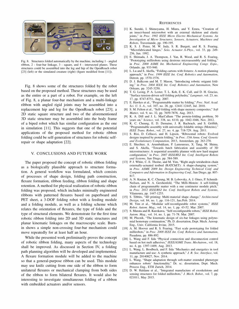
Fig. 8. Structures folded automatically by the machine, including 1 - angledribbon, 2 - four-bar linkage, 3 - square, and 4 - intersected planes. Thesestructures could be assembled into the leg and hip of the OpenRoach robot[23] (left) or the simulated creature (right) (figure modified from [11]).
Fig. 8 shows some of the structures folded by the robotbased on the proposed method. These structures may be usedas the entire or a part of a robot. For example, on the leftof Fig. 8, a planar four-bar mechanism and a multi-linkageribbon with angled rigid joints may be assembled into areplacement hip and leg for the OpenRoach robot [23]; a2D static square structure and two of the aforementioned3D static structure may be assembled into the body frameof a biped robot which has similar configuration as the onein simulation [11]. This suggests that one of the potentialapplications of the proposed method for robotic ribbonfolding could be self-generation of structures for robotic self-repair or shape adaptation [22].
V. CONCLUSIONS AND FUTURE WORK
The paper proposed the concept of robotic ribbon foldingas a biologically plausible approach to structure forma-tion. A general workflow was formulated, which consistsof processes of shape design, folding path construction,flexure formation, ribbon feeding, ribbon folding and shaperetention. A method for physical realization of robotic ribbonfolding was proposed, which includes minimally engineeredribbons with patterned flexures based on paperboard andPET sheet, a 3-DOF folding robot with a feeding moduleand a folding module, as well as a folding scheme whichrelates the orientation of flexures, the type of folds and thetype of structural elements. We demonstrate for the first timerobotic ribbon folding into 2D and 3D static structures andplanar kinematic linkages on the macroscopic scale. Burn-in shows a simple non-crossing four-bar mechanism couldmove repeatedly for at least half an hour.
While the presented work preliminarily proves the conceptof robotic ribbon folding, many aspects of the technologyshall be improved. As discussed in Section IV, a foldingpath planning algorithm will be developed and implemented.A flexure formation module will be added to the machineso that a general-purpose ribbon can be used. This modulemay use knife cutting from one side of the ribbon to formunilateral flexures or mechanical clamping from both sidesof the ribbon to form bilateral flexures. It would also beinteresting to investigate simultaneous folding of a ribbonwith embedded actuators and/or sensors.
REFERENCES
[1] K. Suzuki, I. Shimoyama, H. Miura, and Y. Ezura, “Creation ofan insect-based microrobot with an external skeleton and elasticjoints,” in Proc. 1992 IEEE Micro Electro Mechanical Systems. AnInvestigation of Micro Structures, Sensors, Actuators, Machines andRobots, Travemunde, pp. 190-195.
[2] K. S. J. Pister, M. W. Judy, S. R. Burgett, and R. S. Fearing,“Microfabricated hinges,” Sens. Actuator A-Phys., vol. 33, pp. 249-256, Jun. 1992.
[3] E. Shimada, J. A. Thompson, J. Yan, R. Wood, and R. S. Fearing,“Prototyping millirobots using dextrous microassembly and folding,”in Proc. 2000 ASME Int. Mechanical Engineering Congr. Expo.,Orlando, pp. 933-940.
[4] L. Lu and S. Akella, “Folding cartons with fixtures: A motion planningapproach,” in Proc. 1999 IEEE Int. Conf. Robotics and Automation,Detroit, pp. 1570-1576.
[5] D. J. Balkcom and M. T. Mason, “Introducing robotic origami fold-ing,” in Proc. 2004 IEEE Int. Conf. Robotics and Automation, NewOrleans, pp. 3245-3250.
[6] T. G. Leong, P. A. Lester, T. L. Koh, E. K. Call, and D. H. Gracias,“Surface tension-driven self-folding polyhedra,” Langmuir, vol. 23, no.17, pp. 8747-8751, Aug. 2007.
[7] E. Hawkes et al., “Programmable matter by folding,” Proc. Natl. Acad.Sci. U. S. A., vol. 107, no. 28, pp. 12441-12445, Jul. 2010.
[8] S. M. Felton et al., “Self-folding with shape memory composites,” SoftMatter, vol. 9, no. 32, pp. 7659-7878, Aug. 2013.
[9] K. A. Dill and J. L. MacCallum “The protein-folding problem, 50years on,” Science, vol. 338, no. 6110, pp. 1042-1046, Nov. 2012.
[10] K. C. Cheung, E. D. Demaine, J. R. Bachrach, and S. Griffith,“Programmable assembly with universally foldable strings (Moteins),”IEEE Trans. Robot., vol. 27, no. 4, pp. 718-729. Aug. 2011.
[11] S. Risi, D. Cellucci, and H. Lipson, “Ribosomal robots: Evolveddesigns inspired by protein folding,” in Proc. 15th Annu. Conf. Geneticand Evolutionary Computation, 2013, Amsterdam, pp. 263-270.
[12] E. Shechter, A. Arumbakkam, P. Lamoureux, X. Tang, M. Shima,and S. Akella, “Towards batch fabrication and assembly of 3Dmicrostructures: A sequential assembly planner with new hard magnetconfiguration,” in Proc. 2007 IEEE/RSJ Int. Conf. Intelligent Robotsand Systems, San Diego, pp. 584-589.
[13] P. J. White, C. E. Thorne, and M. Yim, “Right angle tetrahedron chainexternally-actuated testbed (RATChET): A shape-changing system,”in Proc. ASME 2009 Int. Design Engineering Technical Conf. andComputers and Information in Engineering Conf., San Diego, pp. 807-817.
[14] A. N. Knaian, K. C. Cheung, M. B. Lobovsky, A. J. Oines, P. Schmidt-Neilsen, and N. A. Gershenfeld, “The Milli-Motein: A self-foldingchain of programmable matter with a one centimeter module pitch,”in Proc. 2012 IEEE/RSJ Int. Conf. Intelligent Robots and Systems,Vilamoura, pp. 1447-1253.
[15] S. Tibbits, “4D printing: Multi-material shape change,” ArchitecturalDesign, vol. 84, no. 1, pp. 116-121, Jan./Feb. 2014.
[16] M. Yim et al., “Modular self-reconfigurable robot systems,” IEEERobot. Autom. Mag., vol. 14, no. 1, pp. 43-52. Mar. 2007.
[17] S. Murata and H. Kurokawa, “Self-reconfigurable robots,” IEEE Robot.Autom. Mag., vol. 14, no. 1, pp. 71-78. Mar. 2007.
[18] M. Plecnik, “The kinematic design of six-bar linkages using polyno-mial homotopy continuation,” Ph. D. dissertation, Dept. Mech. Aerosp.Eng., Univ. California Irvine, 2015.
[19] A. M. Hoover and R. S. Fearing, “Fast scale prototyping for foldedmillirobots,” in Proc. 2008 IEEE Int. Conf. Robotics and Automation,Pasadena, pp. 886-892.
[20] L. Wang and F. Iida “Physical connection and disconnection controlbased on hot melt adhesives,” IEEE/ASME Trans. Mechatron., vol. 18,no. 4, pp. 1397-1409, Aug. 2013.
[21] L. Wang, L. Brodbeck, and F. Iida “Mechanics and energetics in toolmanufacture and use: A synthetic approach,” J. R. Soc. Interface, vol.11, pp. 20140827, Nov. 2014.
[22] L. Wang, “Shape adaptation through soft-matter extended phenotypeenhances robots’ functionality,” Dr. sc. dissertation, Dept. Mech.Process Eng., ETH Zurich, 2014.
[23] D. W. Haldane et al., “Integrated manufacture of exoskeletons andsensing structures for folded millirobots,” J. Mech. Robot., vol. 7, pp.021011, May 2015.