Embed Size (px)
Citation preview
RoboCupRescue 2011 - Robot League Team
PANDORA (Greece)
Vassilios Petridis, Zoe Doulgeri, Loukas Petrou, Anastasios Delopoulos, Andreas
Symeonidis, Emmanouil Tsardoulias, Charalampos Serenis, Nikos Zikos, Petros Age-
lidis, Miltos Allamanis, Nikos Michailidis, Dimitrios Papageorgiou, Michail Skolari-
kis, Marina Stamatiadou, Nikos Tolis, Dimitrios Vitsios
Department of Electrical and Computer Engineering
Aristotle University of Thessaloniki
Aristotle University Campus
541 24 Thessaloniki, Greece
http://www.ee.auth.gr
Abstract. This is the TDP of the PANDORA Robotics Team of the Aristotle
University of Thessaloniki to sign on for the 2011 RoboCupRescue competi-
tion. We are going to use one tracked platform aiming at scoring the victims in
the yellow arena as well as grasping and carrying a specific object, such as a
small bottle of water.
Introduction
The PANDORA Robotics Team (Program for the Advancement of Non Directed
Operating Robotic Agents) of the Department of Electrical and Computer Engineering
(DECE) of Aristotle University of Thessaloniki (AUTH), Greece aims in developing
an experimental robotic platform for space exploration and victim identification.
Overall objectives of the team are the application of the existing know-how on a real-
life problem, the advancement of the group’s state-of-the-art expertise. The
PANDORA Robotics Team was founded in 2005 and has already participated in the
RoboCupRescue 2008 and 2009 competitions. This year, the team intents to partici-
pate in the yellow and blue arenas.
1. Team Members and Their Contributions
The team comprises 5 faculty members of varying expertise and a compilation of
postgraduate and undergraduate students. The following list provides the names and
responsibilities of the team members.
Team Mentors
Vassilios Petridis, Professor
Zoe Doulgeri, Professor
Loukas Petrou, Associate Professor
Anastasios Delopoulos, Assistant Professor
Andreas Symeonidis, Lecturer
Management Team
Alexios Papadopoulos, Marina Stamatiadou
AI Team
Team Leader: Emmanouil Tsardoulias
SLAM: Georgios Apostolidis, Panagiotis Thomaidis
Planner: Aikaterini Iliakopoulou, Andreas Kargakos
Kinematic Model: Nikolaos Zikos
Software Architecture Team
Team Leader: Miltiadis Allamanis
Testing: Marina Stamatiadou, Pelagia Sikoudi- Amanatidou
GUI: Dimitrios Vitsios, Alaexandros Kalliontzis
Vision Team
Team Leader: Michail Skolarikis
Face recognition: Fragkiskos Koufogiannis
Tag/Hole/Motion detection: Evaggelos Skartados, Georgios Aprilis, Vasilios Tsakalis
Voice recognition Team
Team Leader: Nikolaos Zikos
Sound control: Petros Agelidis
Electronic design Team
Team leader: Charalampos Serenis
Sensors: Nikolaos Tolis, Dimitrios Kanlis
Integration: Alexios Papadopoulos, Nikolaos Tselepis
Mechanical Team
Team Leader: Nikolaos Michailidis
Motor control: Nikolaos Kourous
RoboArm Team
Team Leader: Nikolaos Michailidis
Arm Kinematics: Dimitrios Papageorgiou
Trajectory Planning: Nikolaos Zikos, Maria Grammatikopoulou
The team is going to be represented by 11 members in the competition. Names are
going to be listed in the registration form.
2. Operator Station Set-up and Break-Down (10 minutes)
Three operators are needed for setting up the PANDORA robot: the head operator of
the system, who carries the base station case, and two operators that carry the platform
case.
The initialization process is realized as follows:
Transfer all objects in the area and deploy (3 minutes).
Activate the platform and the base station (3 minutes).
Launch the PANDORA robot OS (2 minutes).
Perform communication check, in order to establish and validate Wi-Fi connec-
tion (1 minute).
Perform system check and diagnostics, in order to verify that all the systems of
the platform are working properly (1 minute).
3. Communications
Following RCR regulations, we are going to use W-LAN 802.11a (5 GHz) and will
wait to be assigned with a channel/band from the organizers during the competition.
Table 1. PANDORA communication protocol
Rescue Robot League
PANDORA (GREECE)
Frequency Channel/Band Power (mW)
5.0 GHz - 802.11a 100
4. Control Method and Human-Robot Interface
The PANDORA robot will operate in three modes: the fully autonomous mode, where
a number of simultaneous processes will be executed in order to achieve autonomous
exploration and victim identification, the tele-operation mode, where the robot will be
totally manipulated by an experienced user, and the semi-autonomous mode, where
the robot will be steered by a user, nevertheless a number of process will assist the
user.
In order to ensure a flexible and modular scheme where reconfiguration is possi-
ble, we opted for a component-based software architecture. The selected architecture
ensures easy testing and integration, while it decouples the overall system from each
component’s actual implementation.
4.1 PANDORA Software Architecture
Having considered various off-the-shelf middleware, we adopted ROS
(http://www.ros.org) for PANDORA’s middleware. A number of factors were consid-
ered during the middleware selection process. A messaging communication scheme
was preferred to a typical RPC-style middleware, due to its inherent ability to promote
loose coupling. Furthermore, messaging provides asynchronous communications with
the ability to control dataflow, which is extremely important for complex intercon-
nected systems. The basic advantages of ROS are: open-source nature, transparent
architecture, wide-spread usage, interoperability with other robot frameworks, quality
of the development toolchain and extensive documentation.
ROS comprises a peer-to-peer network of components (denoted as nodes), which
communicate via messages through the respective ROS infrastructure. The channels
that messages are sent through are called topics. RPC-style communication is also
achieved through services and data persistence is achieved through the Parameter
Server.
PANDORA software architecture consists of several packages implementing
nodes that perform different tasks (vision, sound, navigation, etc). The selected soft-
ware design attempts to decouple nodes from each other as much as possible, thus
minimizing the induced complexity. For all PANDORA packages, provided and re-
quired interfaces were defined through the respective ROS interfaces, thus ensuring
language independence and easy integration. Coding standards were defined and are
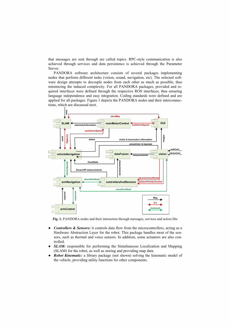
applied for all packages. Figure 1 depicts the PANDORA nodes and their interconnec-
tions, which are discussed next.
Fig. 1. PANDORA nodes and their interaction through messages, services and action libs
● Controllers & Sensors: it controls data flow from the microcontrollers, acting as a
Hardware Abstraction Layer for the robot. This package handles most of the sen-
sors, such as thermal and voice sensors. In addition, some actuators are also con-
trolled.
● SLAM: responsible for performing the Simultaneous Localization and Mapping
(SLAM) for the robot, as well as storing and providing map data.
● Robot Kinematic: a library package (not shown) solving the kinematic model of
the vehicle, providing utility functions for other components.
● Main Motor Control: responsible for controlling the main motors of the robot and
implements basic error handling. Through the Robot Kinematic library, the desired
robot linear and rotational velocities are set. This package has been designed to be
common in all three robot operation modes.
● Arm Control: responsible for solving the kinematic model of the robotic arm,
controlling the arm actuators to reach a goal via a specified trajectory.
● Vision: responsible for handling the stereo camera used for exploration and possi-
ble victim locations, as well as the camera situated on the robotic arm, used for de-
tailed victim identification.
● Vehicle Navigation: responsible for motion planning and navigating the robot
through the unexplored regions of the map or towards a possible victim for further
identification. The package is also responsible for storing and providing victim-
related data, such as victim position.
● Arm Navigation: responsible for navigating the arm configuration space searching
for a victim in that area.
● Data Fusion: it decouples low-level sensor measurements for victim identification
and high-level navigation components. Furthermore, it is responsible for perform-
ing sensor fusion and forwarding possible victim positions (or directions) to the
navigation packages.
● GUI & Connectivity: provides a Graphical User Interface for the robot operator.
In addition it provides the remote controls for tele-operation.
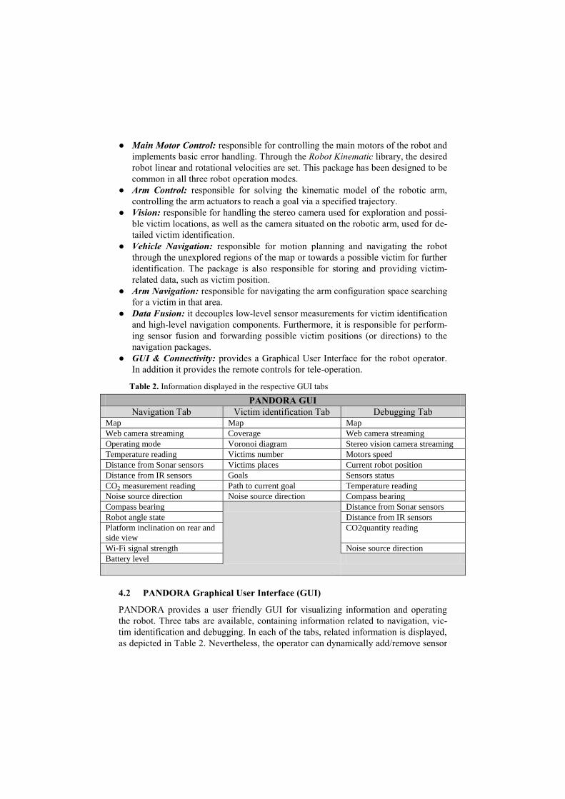
Table 2. Information displayed in the respective GUI tabs
PANDORA GUI
Navigation Tab Victim identification Tab Debugging Tab Map Map Map
Web camera streaming Coverage Web camera streaming
Operating mode Voronoi diagram Stereo vision camera streaming
Temperature reading Victims number Motors speed
Distance from Sonar sensors Victims places Current robot position
Distance from IR sensors Goals Sensors status
CO2 measurement reading Path to current goal Temperature reading
Noise source direction Noise source direction Compass bearing
Compass bearing Distance from Sonar sensors
Robot angle state Distance from IR sensors
Platform inclination on rear and
side view
CO2quantity reading
Wi-Fi signal strength Noise source direction
Battery level
4.2 PANDORA Graphical User Interface (GUI)
PANDORA provides a user friendly GUI for visualizing information and operating
the robot. Three tabs are available, containing information related to navigation, vic-
tim identification and debugging. In each of the tabs, related information is displayed,
as depicted in Table 2. Nevertheless, the operator can dynamically add/remove sensor
information and modify the type and the layout of the widgets displayed in each tab,
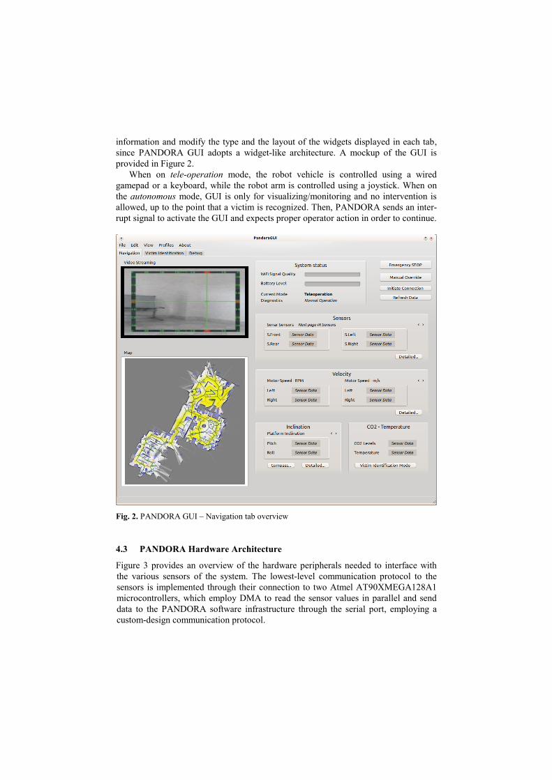
since PANDORA GUI adopts a widget-like architecture. A mockup of the GUI is
provided in Figure 2.
When on tele-operation mode, the robot vehicle is controlled using a wired
gamepad or a keyboard, while the robot arm is controlled using a joystick. When on
the autonomous mode, GUI is only for visualizing/monitoring and no intervention is
allowed, up to the point that a victim is recognized. Then, PANDORA sends an inter-
rupt signal to activate the GUI and expects proper operator action in order to continue.
Fig. 2. PANDORA GUI – Navigation tab overview
4.3 PANDORA Hardware Architecture
Figure 3 provides an overview of the hardware peripherals needed to interface with
the various sensors of the system. The lowest-level communication protocol to the
sensors is implemented through their connection to two Atmel AT90XMEGA128A1
microcontrollers, which employ DMA to read the sensor values in parallel and send
data to the PANDORA software infrastructure through the serial port, employing a
custom-design communication protocol.
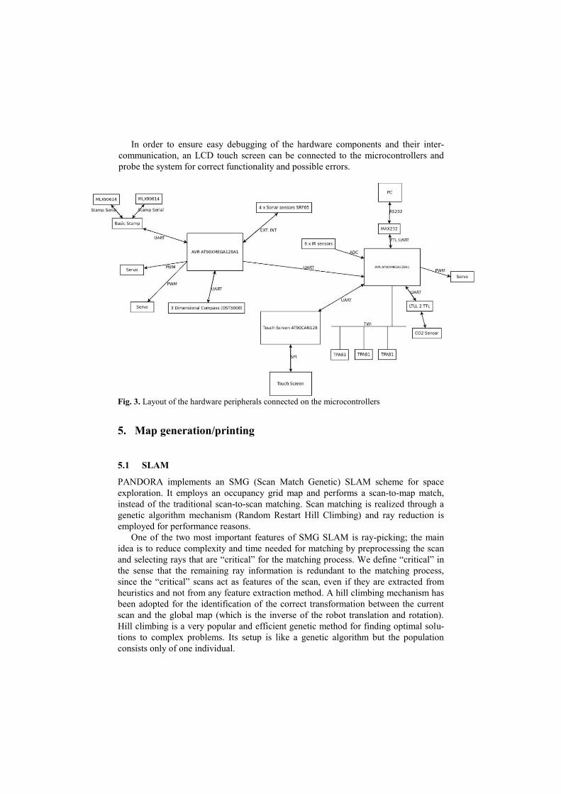
In order to ensure easy debugging of the hardware components and their inter-
communication, an LCD touch screen can be connected to the microcontrollers and
probe the system for correct functionality and possible errors.
Fig. 3. Layout of the hardware peripherals connected on the microcontrollers
5. Map generation/printing
5.1 SLAM
PANDORA implements an SMG (Scan Match Genetic) SLAM scheme for space
exploration. It employs an occupancy grid map and performs a scan-to-map match,
instead of the traditional scan-to-scan matching. Scan matching is realized through a
genetic algorithm mechanism (Random Restart Hill Climbing) and ray reduction is
employed for performance reasons.
One of the two most important features of SMG SLAM is ray-picking; the main
idea is to reduce complexity and time needed for matching by preprocessing the scan
and selecting rays that are “critical” for the matching process. We define “critical” in
the sense that the remaining ray information is redundant to the matching process,
since the “critical” scans act as features of the scan, even if they are extracted from
heuristics and not from any feature extraction method. A hill climbing mechanism has
been adopted for the identification of the correct transformation between the current
scan and the global map (which is the inverse of the robot translation and rotation).
Hill climbing is a very popular and efficient genetic method for finding optimal solu-
tions to complex problems. Its setup is like a genetic algorithm but the population
consists only of one individual.
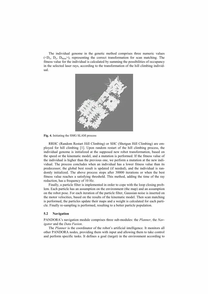
The individual genome in the genetic method comprises three numeric values
(<Dx, Dy, Dtheta>), representing the correct transformation for scan matching. The
fitness value for the individual is calculated by summing the possibilities of occupancy
in the selected laser rays, according to the transformation of the hill climbing individ-
ual.
Fig. 4. Initiating the SMG SLAM process
RRHC (Random Restart Hill Climbing) or SHC (Shotgun Hill Climbing) are em-
ployed for hill climbing [1]. Upon random restart of the hill climbing process, the
individual genome is initialized at the supposed new robot transformation, based on
the speed or the kinematic model, and a mutation is performed. If the fitness value of
the individual is higher than the previous one, we perform a mutation at the new indi-
vidual. The process concludes when an individual has a lower fitness value than its
predecessor; the global best result is updated (if needed), and the individual is ran-
domly initialized. The above process stops after 30000 iterations or when the best
fitness value reaches a satisfying threshold. This method, adding the time of the ray
reduction, has a frequency of 10 Hz.
Finally, a particle filter is implemented in order to cope with the loop closing prob-
lem. Each particle has an assumption on the environment (the map) and an assumption
on the robot pose. For each iteration of the particle filter, Gaussian noise is inserted on
the motor velocities, based on the results of the kinematic model. Then scan matching
is performed, the particles update their maps and a weight is calculated for each parti-
cle. Finally re-sampling is performed, resulting to a better particle population.
5.2 Navigation
PANDORA’s navigation module comprises three sub-modules: the Planner, the Nav-
igator and the Data Fusion.
The Planner is the coordinator of the robot’s artificial intelligence. It monitors all
other PANDORA nodes, providing them with input and allowing them to take control
and perform specific tasks. It defines a goal (target) in the environment according to
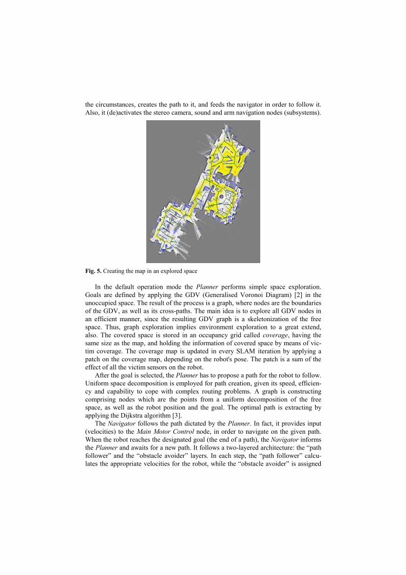
the circumstances, creates the path to it, and feeds the navigator in order to follow it.
Also, it (de)activates the stereo camera, sound and arm navigation nodes (subsystems).
Fig. 5. Creating the map in an explored space
In the default operation mode the Planner performs simple space exploration.
Goals are defined by applying the GDV (Generalised Voronoi Diagram) [2] in the
unoccupied space. The result of the process is a graph, where nodes are the boundaries
of the GDV, as well as its cross-paths. The main idea is to explore all GDV nodes in
an efficient manner, since the resulting GDV graph is a skeletonization of the free
space. Thus, graph exploration implies environment exploration to a great extend,
also. The covered space is stored in an occupancy grid called coverage, having the
same size as the map, and holding the information of covered space by means of vic-
tim coverage. The coverage map is updated in every SLAM iteration by applying a
patch on the coverage map, depending on the robot's pose. The patch is a sum of the
effect of all the victim sensors on the robot.
After the goal is selected, the Planner has to propose a path for the robot to follow.
Uniform space decomposition is employed for path creation, given its speed, efficien-
cy and capability to cope with complex routing problems. A graph is constructing
comprising nodes which are the points from a uniform decomposition of the free
space, as well as the robot position and the goal. The optimal path is extracting by
applying the Dijkstra algorithm [3].
The Navigator follows the path dictated by the Planner. In fact, it provides input
(velocities) to the Main Motor Control node, in order to navigate on the given path.
When the robot reaches the designated goal (the end of a path), the Navigator informs
the Planner and awaits for a new path. It follows a two-layered architecture: the “path
follower” and the “obstacle avoider” layers. In each step, the “path follower” calcu-
lates the appropriate velocities for the robot, while the “obstacle avoider” is assigned
to correct the velocities, so that the robot avoids the obstacles efficiently, irrespective
of the path. The Navigator may also be assigned with another task (goal) before com-
pleting its current one (e.g. a possible victim location is identified). In that case, the
Navigator stores its state in a stack and serves the other path request. In case multiple
interruptions occur, the Navigator follows a similar process.
The Data Fusion module is responsible for filtering out the messages generated by
PANDORA sensors (CO2, MLX thermal sensor, TPA thermal sensor, sound module,
camera). It stores a set of thresholds of all sensors, which are the possibility values of
an eligible valid measurement. Given that a sensor measurement exceeds the thresh-
old, Data Fusion informs the Planner with details. One should mention that thresholds
are not hard-coded and are not crisp; rather, a flexible mechanism has been imple-
mented so that the Planner is informed if a sensor has an almost “valid” value. Upon
victim identification, Data Fusion overrides the Planner and communicates with the
Arm Navigation node directly, until the identification process completes. Then, con-
trol is passed back to the Planner. Messages communicated by Data Fusion abide by
a predefined uniform format, containing the sensor type, the probability of a meas-
urement to be valid, and its direction, in case the sensor is directional.
6. Sensors for Navigation and Localization
The PANDORA robotic platform is equipped with several sensors in order to deter-
mine its current position and its distance from various objects. These sensors are dis-
cussed next.
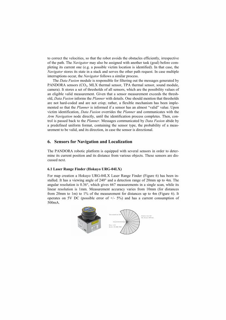
6.1 Laser Range Finder (Hokuyo URG-04LX)
For map creation a Hokuyo URG-04LX Laser Range Finder (Figure 6) has been in-
stalled. It has a viewing angle of 240° and a detection range of 20mm up to 4m. The
angular resolution is 0.36°, which gives 667 measurements in a single scan, while its
linear resolution is 1mm. Measurement accuracy varies from 10mm (for distances
from 20mm to 1m) to 1% of the measurement for distances up to 4m (Figure 6). It
operates on 5V DC (possible error of +/- 5%) and has a current consumption of
500mA.
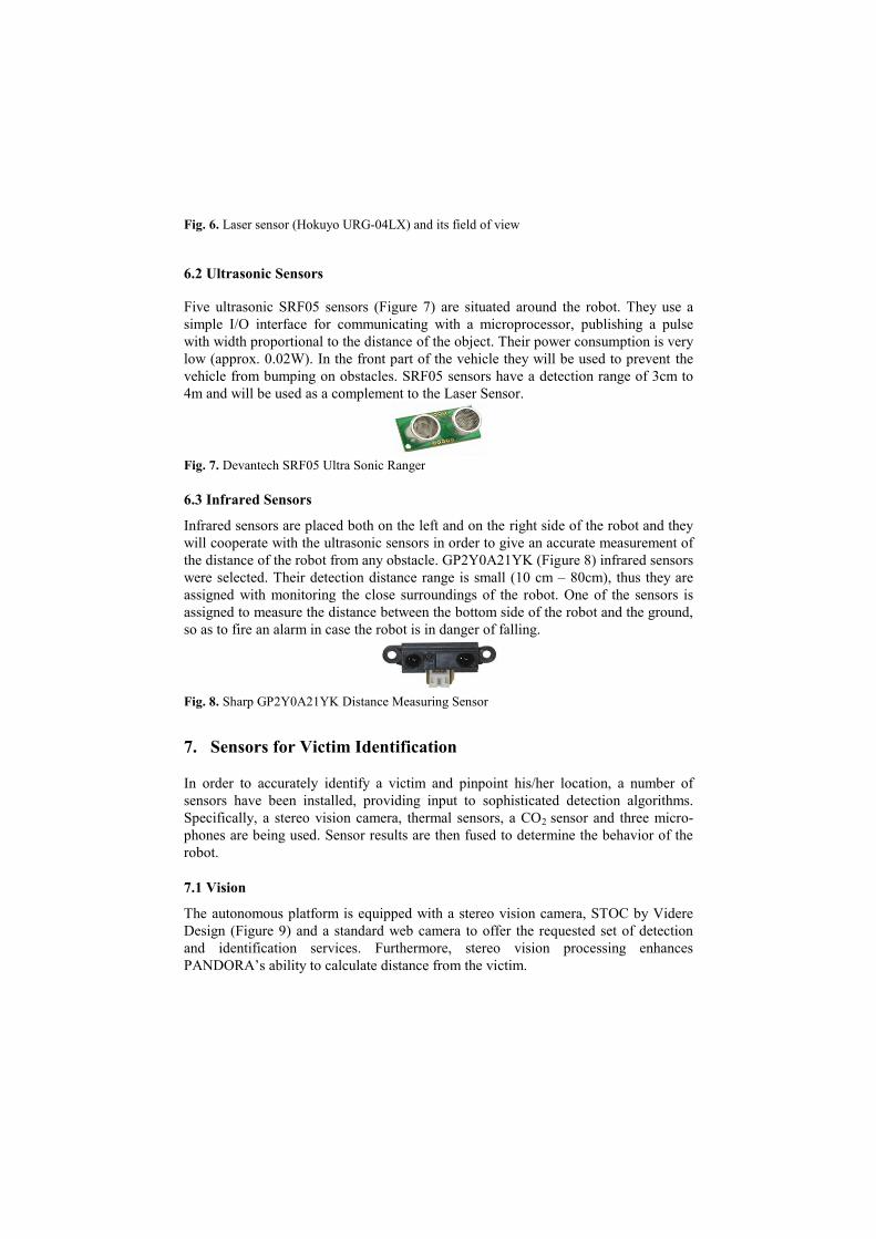
Fig. 6. Laser sensor (Hokuyo URG-04LX) and its field of view
6.2 Ultrasonic Sensors
Five ultrasonic SRF05 sensors (Figure 7) are situated around the robot. They use a
simple I/O interface for communicating with a microprocessor, publishing a pulse
with width proportional to the distance of the object. Their power consumption is very
low (approx. 0.02W). In the front part of the vehicle they will be used to prevent the
vehicle from bumping on obstacles. SRF05 sensors have a detection range of 3cm to
4m and will be used as a complement to the Laser Sensor.
Fig. 7. Devantech SRF05 Ultra Sonic Ranger
6.3 Infrared Sensors
Infrared sensors are placed both on the left and on the right side of the robot and they
will cooperate with the ultrasonic sensors in order to give an accurate measurement of
the distance of the robot from any obstacle. GP2Y0A21YK (Figure 8) infrared sensors
were selected. Their detection distance range is small (10 cm – 80cm), thus they are
assigned with monitoring the close surroundings of the robot. One of the sensors is
assigned to measure the distance between the bottom side of the robot and the ground,
so as to fire an alarm in case the robot is in danger of falling.
Fig. 8. Sharp GP2Y0A21YK Distance Measuring Sensor
7. Sensors for Victim Identification
In order to accurately identify a victim and pinpoint his/her location, a number of
sensors have been installed, providing input to sophisticated detection algorithms.
Specifically, a stereo vision camera, thermal sensors, a CO2 sensor and three micro-
phones are being used. Sensor results are then fused to determine the behavior of the
robot.
7.1 Vision
The autonomous platform is equipped with a stereo vision camera, STOC by Videre
Design (Figure 9) and a standard web camera to offer the requested set of detection
and identification services. Furthermore, stereo vision processing enhances
PANDORA’s ability to calculate distance from the victim.
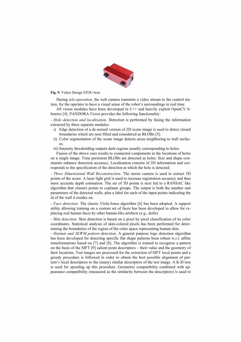
Fig. 9. Videre Design STOC-6cm
During tele-operation, the web camera transmits a video stream to the control sta-
tion, for the operator to have a visual sense of the robot’s surroundings in real time.
All vision modules have been developed in C++ and heavily exploit OpenCV li-
braries [4]. PANDORA Vision provides the following functionality:
- Hole detection and localization. Detection is performed by fusing the information
extracted by three separate modules:
i) Edge detection of a de-noised version of 2D scene image is used to detect closed
boundaries which are next filled and considered as BLOBs [5].
ii) Color segmentation of the scene image detects areas neighboring to wall surfac-
es.
iii) Intensity thresholding outputs dark regions usually corresponding to holes.
Fusion of the above cues results to connected components at the locations of holes
on a single image. Time persistent BLOBs are detected as holes. Size and shape con-
straints enhance detection accuracy. Localization consists of 2D information and cor-
responds to the specification of the direction at which the hole is detected.
- Three Dimensional Wall Reconstruction. The stereo camera is used to extract 3D
points of the scene. A laser light grid is used to increase registration accuracy and thus
more accurate depth estimation. The set of 3D points is next fed to a RANSAC like
algorithm that clusters points to coplanar groups. The output is both the number and
parameters of the detected walls, plus a label for each of the input points indicating the
id of the wall it resides on.
- Face detection. The classic Viola-Jones algorithm [6] has been adopted. A support
utility allowing training on a custom set of faces has been developed to allow for re-
placing real human faces by other human-like artifacts (e.g., dolls).
- Skin detection. Skin detection is based on a pixel by pixel classification of its color
coordinates. Statistical analysis of skin-colored pixels has been performed for deter-
mining the boundaries of the region of the color space representing human skin.
- Hazmat and 3EWM pattern detection. A general purpose logo detection algorithm
has been developed for detecting specific flat shape patterns been robust w.r.t. affine
transformations based on [7] and [8]. The algorithm is trained to recognize a pattern
on the basis of the SIFT [9] salient point descriptors – their value and the geometry of
their locations. Test images are processed for the extraction of SIFT local points and a
greedy procedure is followed in order to obtain the best possible alignment of pat-
tern’s local descriptors to the (many) similar descriptors of the test image. A K-D tree
is used for speeding up this procedure. Geometric compatibility combined with ap-
pearance compatibility (measured as the similarity between the descriptors) is used to
determine whether the pattern appears on the examined image. The same process is
repeated for each pattern.
- Map boundary detection. Colored lines are detected on the basis of their RGB con-
tent, a scheme similar to skin detection is employed.
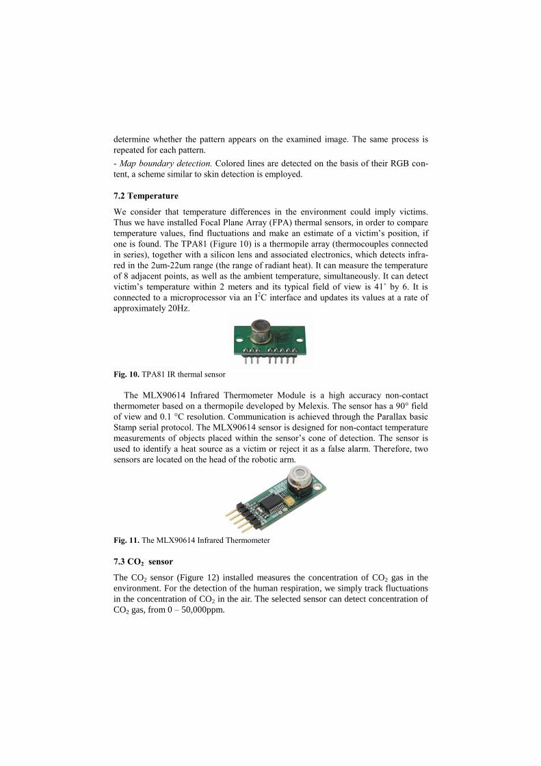
7.2 Temperature
We consider that temperature differences in the environment could imply victims.
Thus we have installed Focal Plane Array (FPA) thermal sensors, in order to compare
temperature values, find fluctuations and make an estimate of a victim’s position, if
one is found. The TPA81 (Figure 10) is a thermopile array (thermocouples connected
in series), together with a silicon lens and associated electronics, which detects infra-
red in the 2um-22um range (the range of radiant heat). It can measure the temperature
of 8 adjacent points, as well as the ambient temperature, simultaneously. It can detect
victim’s temperature within 2 meters and its typical field of view is 41˚ by 6. It is
connected to a microprocessor via an I2C interface and updates its values at a rate of
approximately 20Hz.
Fig. 10. TPA81 IR thermal sensor
The MLX90614 Infrared Thermometer Module is a high accuracy non-contact
thermometer based on a thermopile developed by Melexis. The sensor has a 90° field
of view and 0.1 °C resolution. Communication is achieved through the Parallax basic
Stamp serial protocol. The MLX90614 sensor is designed for non-contact temperature
measurements of objects placed within the sensor’s cone of detection. The sensor is
used to identify a heat source as a victim or reject it as a false alarm. Therefore, two
sensors are located on the head of the robotic arm.
Fig. 11. The MLX90614 Infrared Thermometer
7.3 CO2 sensor
The CO2 sensor (Figure 12) installed measures the concentration of CO2 gas in the
environment. For the detection of the human respiration, we simply track fluctuations
in the concentration of CO2 in the air. The selected sensor can detect concentration of
CO2 gas, from 0 – 50,000ppm.
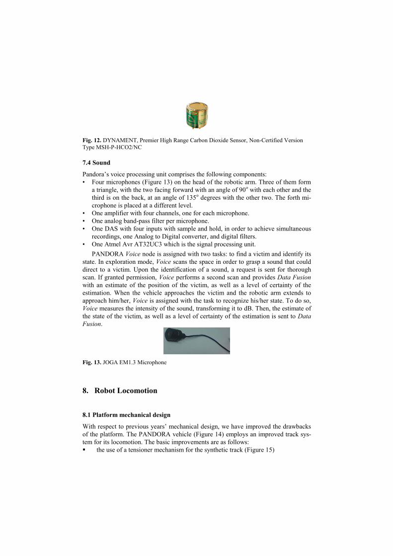
Fig. 12. DYNAMENT, Premier High Range Carbon Dioxide Sensor, Non-Certified Version
Type MSH-P-HCO2/NC
7.4 Sound
Pandora’s voice processing unit comprises the following components:
• Four microphones (Figure 13) on the head of the robotic arm. Three of them form
a triangle, with the two facing forward with an angle of 90o with each other and the
third is on the back, at an angle of 135o degrees with the other two. The forth mi-
crophone is placed at a different level.
• One amplifier with four channels, one for each microphone.
• One analog band-pass filter per microphone.
• One DAS with four inputs with sample and hold, in order to achieve simultaneous
recordings, one Analog to Digital converter, and digital filters.
• One Atmel Avr AT32UC3 which is the signal processing unit.
PANDORA Voice node is assigned with two tasks: to find a victim and identify its
state. In exploration mode, Voice scans the space in order to grasp a sound that could
direct to a victim. Upon the identification of a sound, a request is sent for thorough
scan. If granted permission, Voice performs a second scan and provides Data Fusion
with an estimate of the position of the victim, as well as a level of certainty of the
estimation. When the vehicle approaches the victim and the robotic arm extends to
approach him/her, Voice is assigned with the task to recognize his/her state. To do so,
Voice measures the intensity of the sound, transforming it to dB. Then, the estimate of
the state of the victim, as well as a level of certainty of the estimation is sent to Data
Fusion.
Fig. 13. JOGA EM1.3 Microphone
8. Robot Locomotion
8.1 Platform mechanical design
With respect to previous years’ mechanical design, we have improved the drawbacks
of the platform. The PANDORA vehicle (Figure 14) employs an improved track sys-
tem for its locomotion. The basic improvements are as follows:
the use of a tensioner mechanism for the synthetic track (Figure 15)
a 10mm increase in width and height of the vehicle’s chassis
the adjustment of idle rollers, so as to avoid track oscillations and damage
The metal frame of the robot is made of aluminum. The platform is equipped with
two 50W brushless DC motors with a reduction planetary gearhead. The size of the
robot is 560x230x200 mm. It is solid enough, appropriate to move in different types
of terrain and climb easily a 40o slope.
9. Other Mechanisms
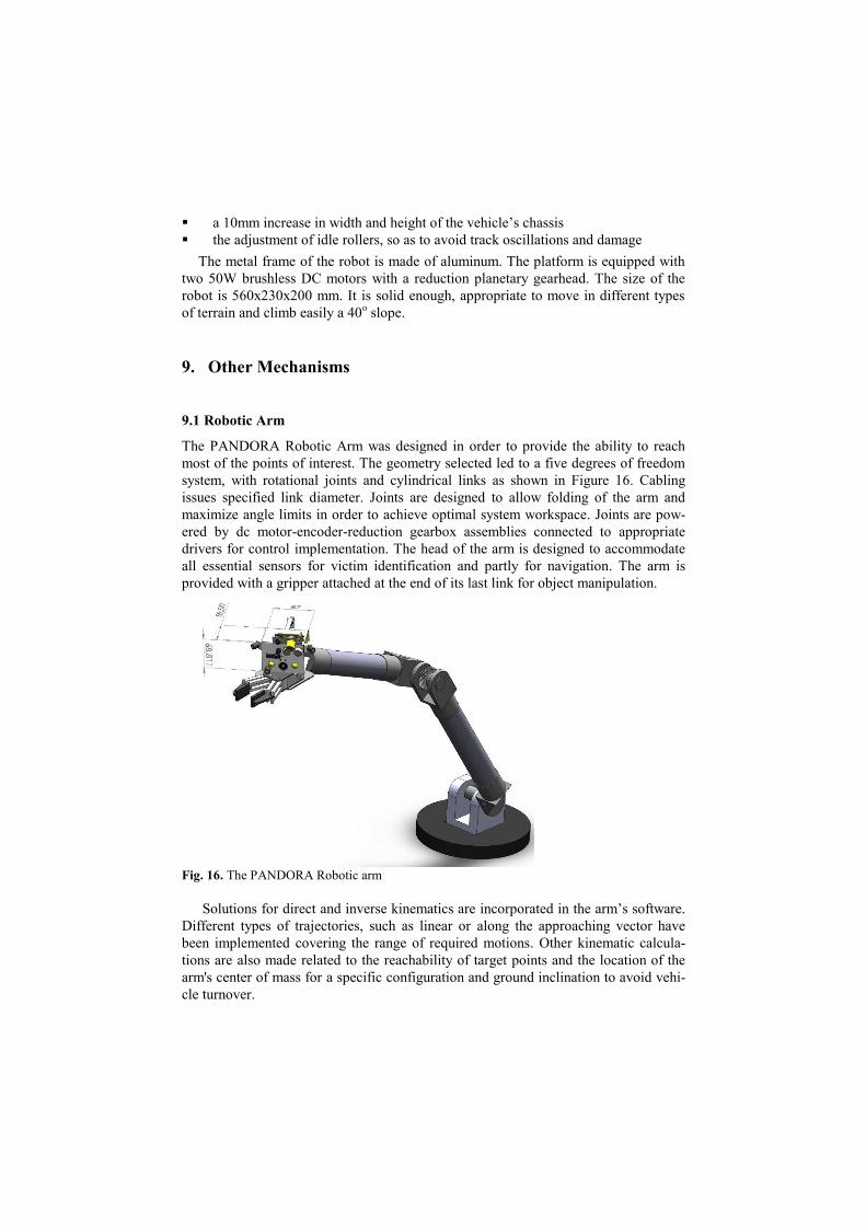
9.1 Robotic Arm
The PANDORA Robotic Arm was designed in order to provide the ability to reach
most of the points of interest. The geometry selected led to a five degrees of freedom
system, with rotational joints and cylindrical links as shown in Figure 16. Cabling
issues specified link diameter. Joints are designed to allow folding of the arm and
maximize angle limits in order to achieve optimal system workspace. Joints are pow-
ered by dc motor-encoder-reduction gearbox assemblies connected to appropriate
drivers for control implementation. The head of the arm is designed to accommodate
all essential sensors for victim identification and partly for navigation. The arm is
provided with a gripper attached at the end of its last link for object manipulation.
Fig. 16. The PANDORA Robotic arm
Solutions for direct and inverse kinematics are incorporated in the arm’s software.
Different types of trajectories, such as linear or along the approaching vector have
been implemented covering the range of required motions. Other kinematic calcula-
tions are also made related to the reachability of target points and the location of the
arm's center of mass for a specific configuration and ground inclination to avoid vehi-
cle turnover.
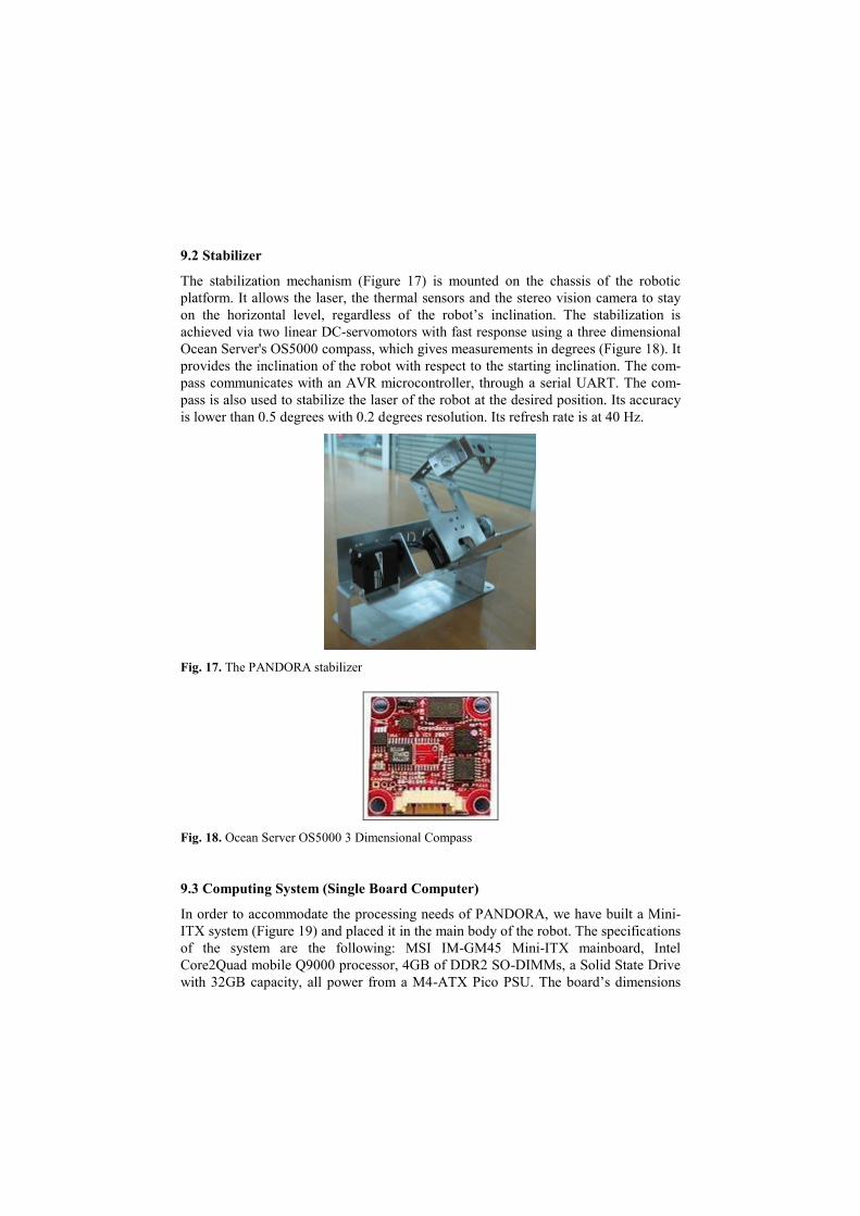
9.2 Stabilizer
The stabilization mechanism (Figure 17) is mounted on the chassis of the robotic
platform. It allows the laser, the thermal sensors and the stereo vision camera to stay
on the horizontal level, regardless of the robot’s inclination. The stabilization is
achieved via two linear DC-servomotors with fast response using a three dimensional
Ocean Server's OS5000 compass, which gives measurements in degrees (Figure 18). It
provides the inclination of the robot with respect to the starting inclination. The com-
pass communicates with an AVR microcontroller, through a serial UART. The com-
pass is also used to stabilize the laser of the robot at the desired position. Its accuracy
is lower than 0.5 degrees with 0.2 degrees resolution. Its refresh rate is at 40 Hz.
Fig. 17. The PANDORA stabilizer
Fig. 18. Ocean Server OS5000 3 Dimensional Compass
9.3 Computing System (Single Board Computer)
In order to accommodate the processing needs of PANDORA, we have built a Mini-
ITX system (Figure 19) and placed it in the main body of the robot. The specifications
of the system are the following: MSI IM-GM45 Mini-ITX mainboard, Intel
Core2Quad mobile Q9000 processor, 4GB of DDR2 SO-DIMMs, a Solid State Drive
with 32GB capacity, all power from a M4-ATX Pico PSU. The board’s dimensions
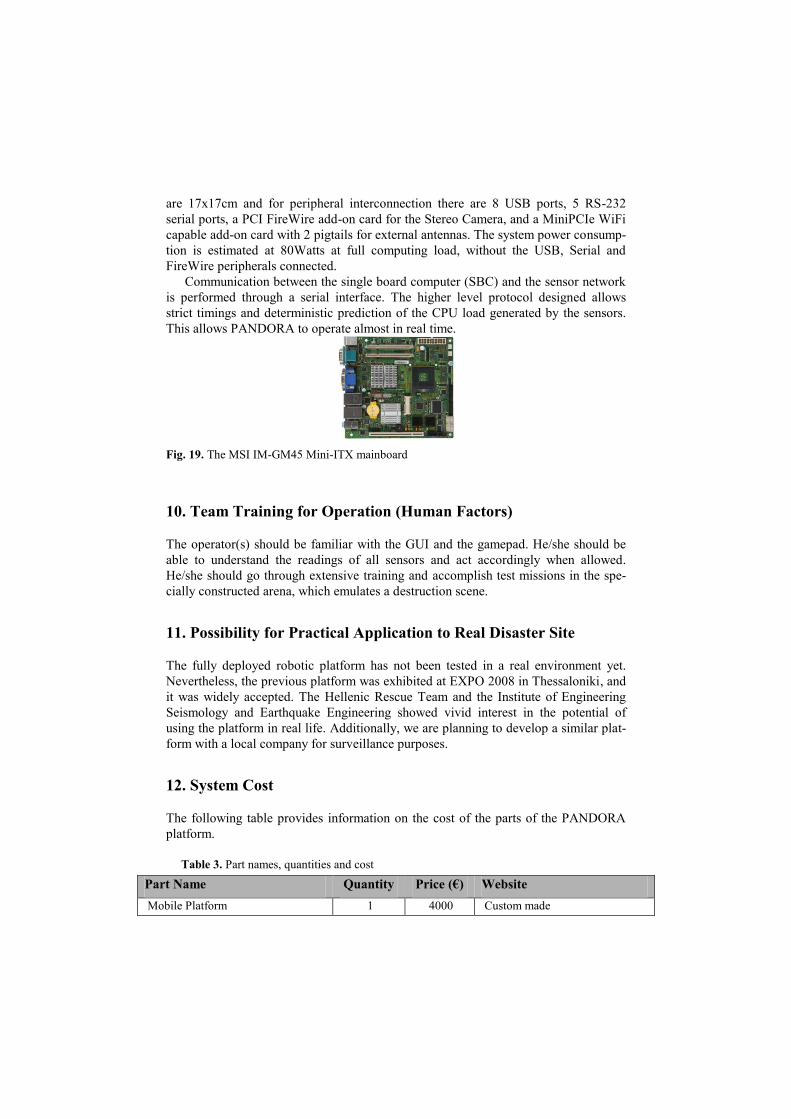
are 17x17cm and for peripheral interconnection there are 8 USB ports, 5 RS-232
serial ports, a PCI FireWire add-on card for the Stereo Camera, and a MiniPCIe WiFi
capable add-on card with 2 pigtails for external antennas. The system power consump-
tion is estimated at 80Watts at full computing load, without the USB, Serial and
FireWire peripherals connected.
Communication between the single board computer (SBC) and the sensor network
is performed through a serial interface. The higher level protocol designed allows
strict timings and deterministic prediction of the CPU load generated by the sensors.
This allows PANDORA to operate almost in real time.
Fig. 19. The MSI IM-GM45 Mini-ITX mainboard
10. Team Training for Operation (Human Factors)
The operator(s) should be familiar with the GUI and the gamepad. He/she should be
able to understand the readings of all sensors and act accordingly when allowed.
He/she should go through extensive training and accomplish test missions in the spe-
cially constructed arena, which emulates a destruction scene.
11. Possibility for Practical Application to Real Disaster Site
The fully deployed robotic platform has not been tested in a real environment yet.
Nevertheless, the previous platform was exhibited at EXPO 2008 in Thessaloniki, and
it was widely accepted. The Hellenic Rescue Team and the Institute of Engineering
Seismology and Earthquake Engineering showed vivid interest in the potential of
using the platform in real life. Additionally, we are planning to develop a similar plat-
form with a local company for surveillance purposes.
12. System Cost
The following table provides information on the cost of the parts of the PANDORA
platform.
Table 3. Part names, quantities and cost
Part Name Quantity Price (€) Website
Mobile Platform 1 4000 Custom made
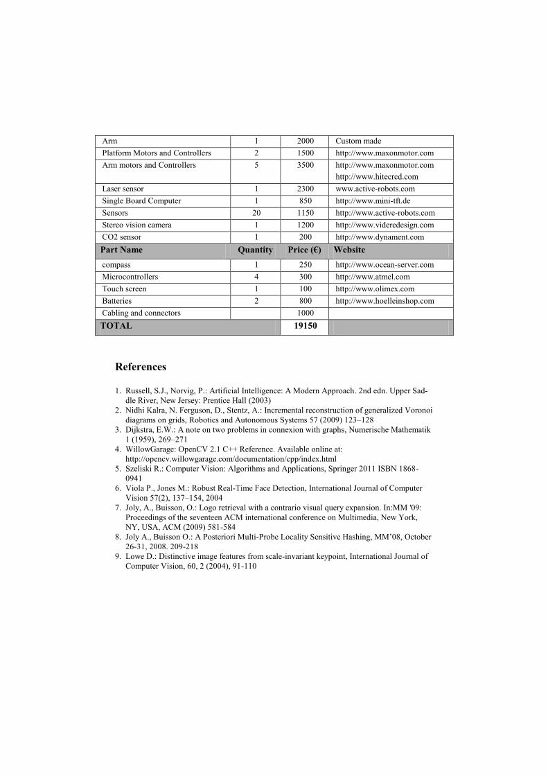
Arm 1 2000 Custom made
Platform Motors and Controllers 2 1500 http://www.maxonmotor.com
Arm motors and Controllers 5 3500 http://www.maxonmotor.com
http://www.hitecrcd.com
Laser sensor 1 2300 www.active-robots.com
Single Board Computer 1 850 http://www.mini-tft.de
Sensors 20 1150 http://www.active-robots.com
Stereo vision camera 1 1200 http://www.videredesign.com
CO2 sensor 1 200 http://www.dynament.com
Part Name Quantity Price (€) Website
compass 1 250 http://www.ocean-server.com
Microcontrollers 4 300 http://www.atmel.com
Touch screen 1 100 http://www.olimex.com
Batteries 2 800 http://www.hoelleinshop.com
Cabling and connectors 1000
TOTAL 19150
References
1. Russell, S.J., Norvig, P.: Artificial Intelligence: A Modern Approach. 2nd edn. Upper Sad-
dle River, New Jersey: Prentice Hall (2003)
2. Nidhi Kalra, N. Ferguson, D., Stentz, A.: Incremental reconstruction of generalized Voronoi
diagrams on grids, Robotics and Autonomous Systems 57 (2009) 123–128
3. Dijkstra, E.W.: A note on two problems in connexion with graphs, Numerische Mathematik
1 (1959), 269–271
4. WillowGarage: OpenCV 2.1 C++ Reference. Available online at:
http://opencv.willowgarage.com/documentation/cpp/index.html
5. Szeliski R.: Computer Vision: Algorithms and Applications, Springer 2011 ISBN 1868-
0941
6. Viola P., Jones M.: Robust Real-Time Face Detection, International Journal of Computer
Vision 57(2), 137–154, 2004
7. Joly, A., Buisson, O.: Logo retrieval with a contrario visual query expansion. In:MM '09:
Proceedings of the seventeen ACM international conference on Multimedia, New York,
NY, USA, ACM (2009) 581-584
8. Joly A., Buisson O.: A Posteriori Multi-Probe Locality Sensitive Hashing, MM’08, October
26-31, 2008. 209-218
9. Lowe D.: Distinctive image features from scale-invariant keypoint, International Journal of
Computer Vision, 60, 2 (2004), 91-110