Embed Size (px)
Citation preview
Manual Road Drainage Chapter 11: Road Surface and Subsurface Drainage Design September 2019
Road Drainage Manual, Transport and Main Roads, September 2019
Copyright
© The State of Queensland (Department of Transport and Main Roads) 2019. Licence
This work is licensed by the State of Queensland (Department of Transport and Main Roads) under a Creative Commons Attribution (CC BY) 4.0 International licence. CC BY licence summary statement In essence, you are free to copy, communicate and adapt this work, as long as you attribute the work to the State of Queensland (Department of Transport and Main Roads). To view a copy of this licence, visit: https://creativecommons.org/licenses/by/4.0/ Translating and interpreting assistance
The Queensland Government is committed to providing accessible services to Queenslanders from all cultural and linguistic backgrounds. If you have difficulty understanding this publication and need a translator, please call the Translating and Interpreting Service (TIS National) on 13 14 50 and ask them to telephone the Queensland Department of Transport and Main Roads on 13 74 68.
Disclaimer While every care has been taken in preparing this publication, the State of Queensland accepts no responsibility for decisions or actions taken as a result of any data, information, statement or advice, expressed or implied, contained within. To the best of our knowledge, the content was correct at the time of publishing. Feedback Please send your feedback regarding this document to: [email protected]

Road Drainage Manual, Transport and Main Roads, September 2019 i
Contents
11 Road surface and subsurface drainage design ..........................................................................1
11.1 Introduction ..................................................................................................................................... 1 11.1.1 Road surface flows .........................................................................................................1 11.1.2 Subsurface flows ............................................................................................................2
11.2 Road surface drainage ................................................................................................................... 2 11.2.1 Pavement runoff .............................................................................................................2 11.2.2 Roadway flow width criteria. ...........................................................................................2 11.2.3 Kerb and channel flow ....................................................................................................6 11.2.4 Edge and median drainage ............................................................................................7 11.2.5 Table drains and table drain blocks................................................................................8 11.2.6 Diversion drains and diversion blocks ............................................................................9 11.2.7 Batter drains ...................................................................................................................9 11.2.8 Catch drains and catch banks ........................................................................................9 11.2.9 Road batter stabilisation .................................................................................................9 11.2.10 Drainage pits ............................................................................................................... 10 11.2.11 Access chambers ........................................................................................................ 17 11.2.12 Access chamber tops .................................................................................................. 17 11.2.13 Reduction in pipe size ................................................................................................. 17 11.2.14 Surcharge chambers ................................................................................................... 18 11.2.15 Pipeline requirements .................................................................................................. 18 11.2.16 Splay pipes .................................................................................................................. 19 11.2.17 Structural requirements of pipelines ............................................................................ 19 11.2.18 Flow velocity limits ....................................................................................................... 19 11.2.19 Pipe grade limits .......................................................................................................... 19 11.2.20 Discharge calculations ................................................................................................ 19 11.2.21 General design procedure ........................................................................................... 20 11.2.22 Hydraulic calculations .................................................................................................. 20
11.3 Aquaplaning .................................................................................................................................. 20 11.3.1 What is aquaplaning? .................................................................................................. 20 11.3.2 Causal factors .............................................................................................................. 20 11.3.3 Road surfacing ............................................................................................................ 20 11.3.4 Tyres ............................................................................................................................ 20 11.3.5 The road-tyre interface ................................................................................................ 20 11.3.6 Skid resistance ............................................................................................................ 20 11.3.7 Assessment – water film depth ................................................................................... 21 11.3.8 Assessment – aquaplaning potential........................................................................... 21 11.3.9 Quick assessment ....................................................................................................... 22 11.3.10 Puddles/wheel ruts ...................................................................................................... 22 11.3.11 Guidance to reduce aquaplaning potential .................................................................. 22 11.3.12 Worked example .......................................................................................................... 22
11.4 Subsurface drainage ..................................................................................................................... 22 11.4.1 Moisture in roads ......................................................................................................... 22 11.4.2 Control of road moisture .............................................................................................. 23 11.4.3 Types of subsurface drainage ..................................................................................... 24 11.4.4 Requirements of filter materials ................................................................................... 28 11.4.5 Design procedure ........................................................................................................ 29 11.4.6 Location of subsoil drains ............................................................................................ 29 11.4.7 Transverse subsurface drains ..................................................................................... 32 11.4.8 Cut-off drains ............................................................................................................... 32 11.4.9 Design of cut-off drains ............................................................................................... 32 11.4.10 Size of drain ................................................................................................................. 32 11.4.11 Materials ...................................................................................................................... 32 11.4.12 Access to subsurface drains ....................................................................................... 32 11.4.13 Lowering of ground water table ................................................................................... 33 11.4.14 Schilfgaarde’s Method ................................................................................................. 33

Road Drainage Manual, Transport and Main Roads, September 2019 ii
11.4.15 Draining an inclined aquifer ......................................................................................... 33 11.4.16 Design of a filter blanket to lower a water table .......................................................... 33 11.4.17 Capillary rise in soils .................................................................................................... 33
Tables
Table 11.2.2.2 – Roadway flow limitations – major storm, longitudinal drainage ................................... 6
Figures
Figure 11.2.2.1(a) – Allowable flow widths on roadways –10% AEP flood (cross-section views) .......... 3
Figure 11.2.2.1(b) – Allowable flow widths on roadways – 10% AEP flood (plan views) ....................... 4
Figure 11.2.3.1(a) – General kerb profiles or shapes ............................................................................. 7
Figure 11.2.3.1(b) – Edge treatment at erodible slopes .......................................................................... 7
Figure 11.2.10.2 – Procedure to determine kerb inlet positions on grade ............................................ 13
Figure 11.2.10.7(a) – Field inlet under weir flow ................................................................................... 15
Figure 11.2.10.7(b) – Under orifice flow conditions ............................................................................... 15
Figure 11.2.10.7(c) – Minimum lip width required for scour protection ................................................. 17
Figure 11.4.1 – Sources of moisture (Adapted from ARRB (1987)) ..................................................... 23
Figure 11.4.3(a) – Drainage for surface infiltration with subsoil drains ................................................. 24
Figure 11.4.3(b) – Drainage for surface infiltration with free draining layer .......................................... 25
Figure 11.4.3(c) – Drainage trenches to lower water table ................................................................... 25
Figure 11.4.3(d) – Horizontal filter blanket to lower water table ............................................................ 25
Figure 11.4.3(e) – Trenches to intercept flow through an inclined permeable layer ............................. 26
Figure 11.4.3(f) – Permeable filter to lower the effect of head from a permeable aquifer .................... 26
Figure 11.4.3(g) – Standard subsoil drains ........................................................................................... 27
Figure 11.4.3(h) – Subsoil drain outlets and cleanouts ......................................................................... 28
Figure 11.4.6(a) – Location of subsoil drains (divided road) ................................................................. 30
Figure 11.4.6(b) – Subsoil drains – Low embankment or transition from embankment to cut .............. 30
Figure 11.4.6(c) – Subsoil drains in cuttings ......................................................................................... 31
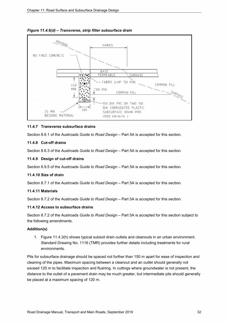
Figure 11.4.6(d) – Transverse, strip filter subsurface drain .................................................................. 32

Chapter 11: Road Surface and Subsurface Drainage Design
Road Drainage Manual, Transport and Main Roads, September 2019 1
11 Road surface and subsurface drainage design
11.1 Introduction
Road surface drainage deals with the drainage of stormwater runoff from the road surface and the surfaces adjacent to the road formation. Several elements can be used to intercept or capture this runoff and facilitate its safe discharge to an appropriate receiving location. These elements include:
• kerb and channel
• edge and median drainage
• table drains and blocks
• diversion drains and blocks
• batter drains
• catch drains and banks
• drainage pits
• pipe networks.
Subsurface drainage deals with the interception and disposal of subterranean (groundwater) flows with predominate drainage element being sub-soil drainage.
11.1.1 Road surface flows
After falling onto road surfaces, rainfall runoff drains to the lowest point and in moving across the road surface forms a layer of water of varying thickness. This water can be a hazard to the motorist. Splash and heavy spray are thrown up by moving vehicles, reducing visibility, while the water on the pavement reduces friction between the tyres and road surface.
Excessive water on the pavement, whether ponded or flowing, can represent a real risk of aquaplaning or the build-up of a layer of water between the vehicle tyre and the road surface, which leads to a total loss of grip. While part of road surface drainage, aquaplaning is a critically important aspect of road surface drainage and is discussed within its own section, Section 11.3.
On reaching the lowest point, runoff is channelled along the pavement edge via kerbing/kerb and channelling or discharged over the shoulders to a suitable collection system such as a natural watercourse, table drain or piped drainage system (pipe network).
Some degree of water quality treatment may be needed between the road and the receiving water to remove litter, heavy metals, nutrients and oils. In this regard, there is a growing trend to place some form of grass filter between the road surface and any concrete-lined drain. This form of drainage is known as ‘indirectly connected impervious surface area’ and is a form of water sensitive urban design (see Chapter 7).
In all cases, design of the elements for this runoff must adequately cater for the safety and convenience of road users, including pedestrians, and protect adjacent properties and the road pavement from damage.
Where erosion of the batters is not considered likely, pavement runoff discharged over the shoulders and batters directly to the natural surface may be acceptable in some rural situations such as a level stretch of road in flat country.

Chapter 11: Road Surface and Subsurface Drainage Design
Road Drainage Manual, Transport and Main Roads, September 2019 2
Where batter erosion is likely/possible, the use of a concrete or asphalt kerb/dyke should be investigated.
11.1.2 Subsurface flows
Section 8.1 of the Austroads Guide to Road Design – Part 5A is accepted for this section subject to the following amendments.
Addition(s)
1. Further consideration should be given to the detailed recommendations in respect of design and installation of subsoil drains contained within Special Report No. 35 Subsurface Drainage of Road Structures (ARRB 1987).
11.2 Road surface drainage
11.2.1 Pavement runoff
Pavement runoff is calculated by the Rational Formula:
𝑄𝑄𝑦𝑦 = 𝑘𝑘.𝐶𝐶𝑦𝑦 . 𝐼𝐼𝑡𝑡𝑡𝑡,𝑦𝑦 .𝐴𝐴 (refer to Chapter 5)
The contribution to the flow at the kerb or median channel is given by a modification of the Rational Formula and is expressed as:
𝑞𝑞𝑦𝑦 =𝐶𝐶𝑦𝑦 . 𝐼𝐼𝑡𝑡𝑡𝑡,𝑦𝑦 .𝑊𝑊3.6 × 10⁶
where qy = contribution per longitudinal metre of pavement (m³/s) for an ARI1 of y years
Cy = runoff coefficient (dimensionless) for an ARI of y years (refer Chapter 5)
Itc,y = average rainfall intensity (mm/h) for design duration of tc and ARI of y years (refer Chapter 5)
W = width of contributing cross-section (m)
A runoff coefficient C10 of 0.9 (or higher) is typical for most road surfaces.
Where the pavement width varies or the runoff coefficient is different, then total runoffs or lengths for given runoffs have to be calculated algebraically.
11.2.2 Roadway flow width criteria.
For the safety of vehicular traffic other than requirements against aquaplaning, flow width criteria apply. Water depths and velocities are also limited by the width restrictions.
Flow widths in both the minor and major storms need to be considered.
11.2.2.1 Minor storm flow limits
Adopting the 10% AEP flood as that arising from the design minor storm of the same likelihood, flow width criteria are shown on Figures 11.2.2.1(a) and 11.2.2.1(b).
1 Use of the ARI terminology is retained in this instance as the Rational Method nomenclature was developed using this. The relationship between ARI and the departments preferred AEP terminology is explained in Chapter 2
Chapter 11: Road Surface and Subsurface Drainage Design
Road Drainage Manual, Transport and Main Roads, September 2019 3
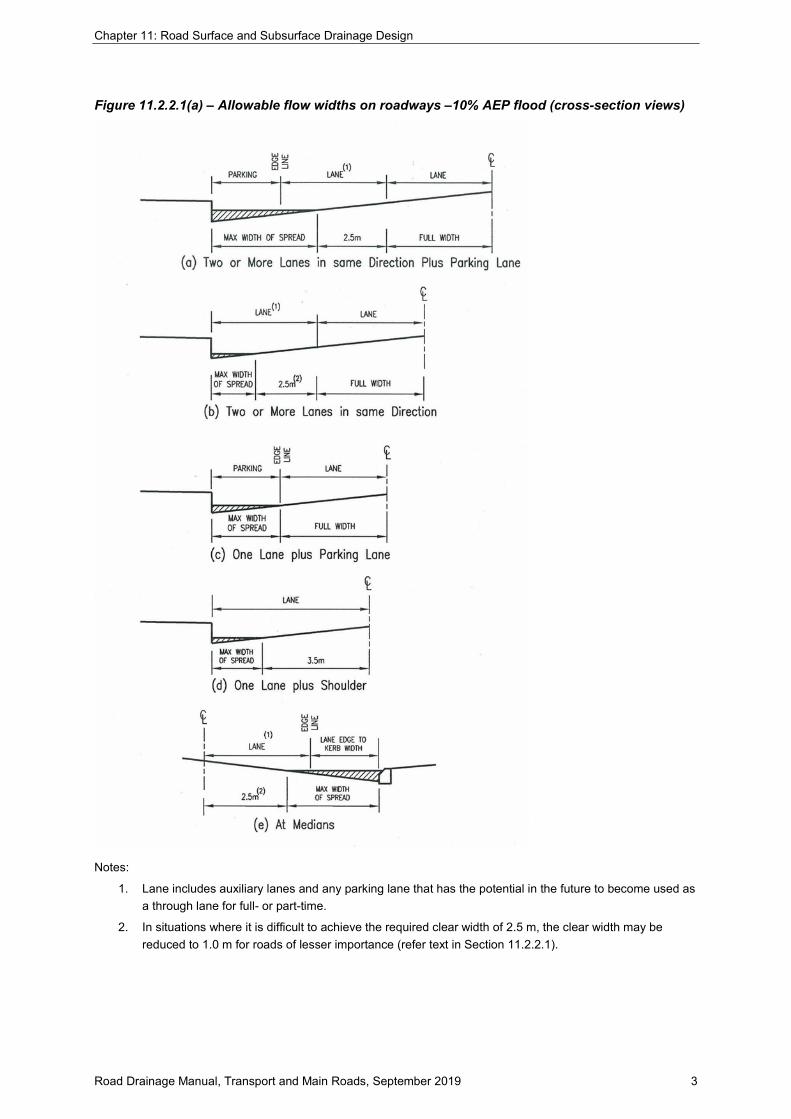
Figure 11.2.2.1(a) – Allowable flow widths on roadways –10% AEP flood (cross-section views)
Notes:
1. Lane includes auxiliary lanes and any parking lane that has the potential in the future to become used as a through lane for full- or part-time.
2. In situations where it is difficult to achieve the required clear width of 2.5 m, the clear width may be reduced to 1.0 m for roads of lesser importance (refer text in Section 11.2.2.1).

Chapter 11: Road Surface and Subsurface Drainage Design
Road Drainage Manual, Transport and Main Roads, September 2019 4
Figure 11.2.2.1(b) – Allowable flow widths on roadways – 10% AEP flood (plan views)
Notes:
1. Refer to Figure 11.2.2.1(a).
2. In situations where it is difficult to achieve the required clear width of 2.5 m, the clear width may be reduced to 1.0 m for roads of lesser importance (refer text in Section 11.2.2.1).
3. At pedestrian crossings check both width and velocity (refer text in Section 11.2.2.1).
4. See Section 11.2.2.2 for allowable widths in major storms.

Chapter 11: Road Surface and Subsurface Drainage Design
Road Drainage Manual, Transport and Main Roads, September 2019 5
These diagrams represent the following:
a) for two lanes (or more) in the same direction plus parking lane, the maximum allowable width of spread leaves the inside and any lane-locked lanes clear plus 2.5 m clear width in the remaining lane; that is, water is kept out of the wheel paths of lanes. The term ‘lane’ includes auxiliary lanes and any parking lane that has the potential to become used as a full or part-time through lane
b) for two lanes (or more) in the same direction, the maximum allowable width of spread leaves the inside and any lane-locked lanes clear plus 2.5 m clear width in the remaining lane. The term ‘lane’ includes auxiliary lanes
c) for one lane plus parking lane, water is not allowed to spread past the edge of the through lane
d) for one lane, a minimum clear width of 3.5 m is to remain in the lane
e) at medians, the allowable spread of water leaves 2.5 m clear width in the traffic lane next to the median. The term ‘lane’ includes auxiliary lanes
f) at intersections without left slip lanes, the allowable width of spread adjacent to the kerb is 1.0 m
g) at intersections with single left slip lanes, the allowable width of spread leaves 3.5 m clear width in the slip lane
h) at intersections with dual left slip lanes, the allowable width of spread leaves 2.5 m clear in outer turning lane.
In situations where it is difficult to achieve the required clear width of 2.5 m in cases ‘(b)’, ‘(e)’ and ‘(h)’ above, the clear width may be reduced to 1.0 m for roads of lesser importance. This practice is not recommended for reasons of consistency and the use of a reduced clear width must be specified in design brief and/or contract documents or approved by the department.
Where pedestrians will cross the road, allow no more than 0.5 m width of spread in a 1 Exceedances per Year (EY) flood. The 0.5 m requirement is based on the typical overstep/short jump of most people. Checks should also be undertaken on the flow velocity. Where the risk of injury is reasonably foreseeable, velocities should be limited by:
dg.Vavg ≤ 0.3 m²/s
where dg = flow depth in the channel adjacent to the kerb (m)
Vavg = average velocity of the flow (m/s)
There is also a water depth-velocity relationship which is applicable for both minor and major floods in the channel next to a kerb. This is for pedestrian safety in longitudinal flows along the kerb and is shown on Table 11.2.2.2.
Where a road contains separate bicycle lanes then the flow spread should be limited to 0.5 m. For a shared bicycle and vehicle lane, the flow spread width should be limited to 1.5 m. Design rainfall intensity to use for on-road cyclist facilities is the lesser of the 63% AEP, five-minute rainfall event, or 50 mm/h.

Chapter 11: Road Surface and Subsurface Drainage Design
Road Drainage Manual, Transport and Main Roads, September 2019 6
11.2.2.2 Major storm flow limits
The major storm is usually of a 2% AEP to 1% AEP, depending on the local authority. The 1% AEP flood should be used as a check flood at least to allow consideration of any detrimental effects.
Table 11.2.2.2 gives roadway flow limits for a major storm, for the longitudinal drainage system, with particular reference to floor levels of adjacent buildings, pedestrian and vehicle safety.
At sags in state-controlled roads, additional inlets and underground drainage should be provided, if necessary, to limit ponded water in a 2% AEP storm so that there is:
• one lane in each direction of travel, free of water, in a multi-lane road, or
• a width of 3.5 m clear of water down the centre of a two-lane road.
Table 11.2.2.2 – Roadway flow limitations – major storm, longitudinal drainage
Situation Roadway flow width and depth limitation
Where floor levels of adjacent buildings are above road level
Total flow contained within road reserve Peak water levels at least 300 mm below floor level of adjacent buildings (i.e. freeboard of at least 300 mm)
Where floor levels of adjacent buildings are less than 350 mm above top of kerb • where fall on footpath towards kerb is
greater than 100 mm • where fall on footpath towards kerb is
less than 100 mm Where no kerb is provided
Water depth to be limited to 50 mm above top of kerb Water depth to be limited to top of kerb in conjunction with a footpath profile that prevents flow from the roadway entering onto the adjacent property. Above depths shall be measured from the theoretical top of kerb
Pedestrian safety# a) no obvious danger b) obvious danger
dgVavg ≤ 0.6 m²/s dgVavg ≤ 0.4 m²/s
Vehicle safety Maximum energy level of 300 mm above roadway surface for areas subject to transverse flow
Notes:
1. dg = flow depth in the channel adjacent to the kerb, i.e. at the invert (m)
2. Vavg = average velocity of the flow (m/s)
3. # Obvious danger is interpreted as areas where pedestrians are directed to or most likely to cross water paths (such as marked crossings and corners of intersections).
11.2.3 Kerb and channel flow
Section 5.5.1 of the Austroads Guide to Road Design – Part 5A is accepted for this section with the following amendments.
Difference(s)
1. The Rational Method in the form of equation 14 as presented in Section 5.5.1 of the Austroads Guide to Road Design – Part 5A is not to be used for departmental projects. The pavement runoff is to be determined as per the guidance in Section 11.2.1 of this manual.
11.2.3.1 Kerb types and uses
Approved kerb types with channels are shown in Standard Drawing 1033 (TMR). General kerb profiles or shapes are shown in Figure 11.2.3.1(a).
Chapter 11: Road Surface and Subsurface Drainage Design
Road Drainage Manual, Transport and Main Roads, September 2019 7
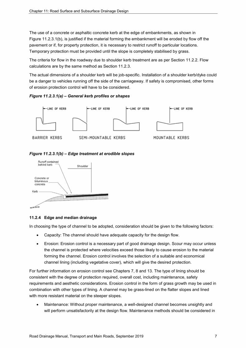
The use of a concrete or asphaltic concrete kerb at the edge of embankments, as shown in Figure 11.2.3.1(b), is justified if the material forming the embankment will be eroded by flow off the pavement or if, for property protection, it is necessary to restrict runoff to particular locations. Temporary protection must be provided until the slope is completely stabilised by grass.
The criteria for flow in the roadway due to shoulder kerb treatment are as per Section 11.2.2. Flow calculations are by the same method as Section 11.2.3.
The actual dimensions of a shoulder kerb will be job-specific. Installation of a shoulder kerb/dyke could be a danger to vehicles running off the side of the carriageway. If safety is compromised, other forms of erosion protection control will have to be considered.
Figure 11.2.3.1(a) – General kerb profiles or shapes
Figure 11.2.3.1(b) – Edge treatment at erodible slopes
11.2.4 Edge and median drainage
In choosing the type of channel to be adopted, consideration should be given to the following factors:
• Capacity: The channel should have adequate capacity for the design flow.
• Erosion: Erosion control is a necessary part of good drainage design. Scour may occur unless the channel is protected where velocities exceed those likely to cause erosion to the material forming the channel. Erosion control involves the selection of a suitable and economical channel lining (including vegetative cover), which will give the desired protection.
For further information on erosion control see Chapters 7, 8 and 13. The type of lining should be consistent with the degree of protection required, overall cost, including maintenance, safety requirements and aesthetic considerations. Erosion control in the form of grass growth may be used in combination with other types of lining. A channel may be grass-lined on the flatter slopes and lined with more resistant material on the steeper slopes.
• Maintenance: Without proper maintenance, a well-designed channel becomes unsightly and will perform unsatisfactorily at the design flow. Maintenance methods should be considered in

Chapter 11: Road Surface and Subsurface Drainage Design
Road Drainage Manual, Transport and Main Roads, September 2019 8
the design of drainage channels so that the type of channel section adopted will be suitable for the methods and equipment that will be used for maintenance.
For example, in the majority of cases, a concrete invert should be considered for ‘V’-shaped channels because of the difficulty in maintaining the section with the maintenance machinery available. On grades less than 0.5% and for most cross-sections, a concrete invert is essential in assisting the discharge of low flow. Maintenance operations are extremely difficult with saturated conditions in the vicinity of an unlined invert.
The minimum grade for unlined drains, including table drains, is 0.5% and 0.2% for lined drains; however, 0.3% may be regarded as the minimum practical slope for construction.
Where a concrete invert is necessary due to minimum grade requirements, the invert shall comprise a Type 22 section (Refer SD1033) or equivalent. Additional lining may be required if erosion potential exists.
11.2.4.1 Design of edge and median drainage
Section 2.12.1 of the Austroads Guide to Road Design – Part 5B is accepted for this section subject to the following amendments.
Addition(s)
1. The pavement runoff is calculated using the Rational Method Formula (refer Section 11.2.1), but consideration must be given to the different runoff coefficients for pavement and the median surfaces.
11.2.5 Table drains and table drain blocks
Section 2.13 of the Austroads Guide to Road Design – Part 5B is accepted for this section.
11.2.5.1 Table drains
Section 2.13.1 of the Austroads Guide to Road Design – Part 5B is accepted for this section with the following amendments.
Addition(s)
1. Designers must check the hydraulic characteristics of flows in table drains for the design conditions. This is to ensure that sufficient capacity is provided and the table drain is not susceptible to erosion. Determination of depth and velocity of flow within the table drain can be undertaken using Manning’s Equation.
11.2.5.2 Table drain blocks
Section 2.13.2 of the Austroads Guide to Road Design – Part 5B is accepted for this section, subject to the following amendments.
Addition(s)
1. A marker post (refer Standard Drawing 1358 (TMR) should be placed on/adjacent to table drain blocks to alert maintenance personnel of their existence.
11.2.5.3 Adjoining projects
Another important design aspect regarding table drains is where new and previous projects join. The impacts of discharge from one project to the next must be considered/incorporated. The shape and grade of adjoining table drains should also match. Where the shape and grade do not match, a

Chapter 11: Road Surface and Subsurface Drainage Design
Road Drainage Manual, Transport and Main Roads, September 2019 9
suitable transition or other mitigating treatment must be designed to ensure that scour does not occur and/or that stormwater does not flow out onto the road surface.
11.2.6 Diversion drains and diversion blocks
Section 2.13.3 of the Austroads Guide to Road Design – Part 5B is accepted for this section.
11.2.7 Batter drains
Section 2.14 of the Austroads Guide to Road Design – Part 5B is accepted for this section.
11.2.7.1 Design procedure
Section 2.14.1 of the Austroads Guide to Road Design – Part 5B is accepted for this section.
11.2.7.2 Design notes
Section 2.14.1 of the Austroads Guide to Road Design – Part 5B is accepted for this section.
11.2.8 Catch drains and catch banks
Section 2.15.1 of the Austroads Guide to Road Design – Part 5B is accepted for this section subject to the following amendments.
Addition(s)
1. These devices are generally located no closer than 2.0 m from the edge of the cuttings in order to minimise possible undercutting of the top of the batter.
11.2.8.1 Design procedure for catch drains
Section 2.15.3 of the Austroads Guide to Road Design – Part 5B is accepted for this section.
11.2.9 Road batter stabilisation
An integral part of surface drainage is the design of erosion control measures to the finished surfaces.
The downstream face of an elevated road embankment across a floodplain will need to be protected from the erosive forces that occur during overtopping. The extent of this protection will depend on the expected tailwater level at the commencement of overtopping (refer Chapter 10).
Some roads are designed to be overtopped and the erosive potential is not as severe as those for floodways. Rather than overtopping, rainfall, wind and runoff from the top of the road formation (unless kerbs are in place) are the key agents for erosion.
Designers need to develop and assess options and determine the most suitable solution for the situation.
The types of protection measures available for consideration are:
• revegetation
• biodegradable blankets in association with permanent revegetation (the relevant specification is MRTS16 Landscape and Revegetation Works (TMR2017b))
• chemical surface stabilisers and soil/cement treatment (the relevant specifications are MRTS03 Drainage, Retaining Structures and Protective Treatments (TMR 2019a) and MRTS16 Landscape and Revegetation Works (TMR2017b))
Chapter 11: Road Surface and Subsurface Drainage Design
Road Drainage Manual, Transport and Main Roads, September 2019 10
• bank protection techniques commonly associated with bridge abutments (relevant standards are MRTS03 Drainage, Retaining Structures and Protective Treatments (TMR 2019a) and MRTS16 Landscape and Revegetation Works (TMR2017b))
• and Standard Drawings 2232, 2233, 2234, 2235, 2236, 2237, 2238, 2241 (TMR), which also shows other types of protection for bridge abutments))
• benching to create permanent drainage lines to reduce surface drainage (relevant specifications are MRTS03 Drainage, Retaining Structures and Protective Treatments (TMR 2019a), MRTS04 General Earthworks (TMR2018c) and MRTS16 Landscape and Revegetation Works (TMR2017b))
• kerbs at the top edges of the road formations diverting runoff from rainfall on the pavement and shoulders to batter chutes (relevant standards are MRTS03 Drainage, Retaining Structures and Protective Treatments (TMR 2019a) and Standard Drawing 1033 (TMR))
• catch drains and catch banks used to divert water to batter chutes or completely away from the batter slope (relevant standards are MRTS03 Drainage, Retaining Structures and Protective Treatments (TMR 2019a) and MRTS16 Landscape and Revegetation Works (TMR2017b) and Standard Drawing 1178 (TMR))
• proprietary batter chutes.
11.2.10 Drainage pits
Drainage pits are field inlets and gullies collecting surface flows to the underground drainage system and access chambers at pipe junctions and for maintenance.
Inlet locations should be optimised to collect the design surface flows with the minimum number of installations and, of course, to reduce surface water to an acceptable width.
This requires computations for each area contributing flow to the inlets. Areas may comprise both road pavement and adjacent urban, suburban or rural land.
Proprietary pre-cast pit segments and grates or covers are available. The department has standardised some of the more common field inlets, gullies and access chambers as Standard Drawings Nos. 1307, 1308, 1309, 1310, 1311, 1312, 1313, 1321, 1322, 1442, 1443, 1444, 1445 and 1561 (TMR).
Four types of kerb inlets are in common use, they are:
• grate only, such as field inlets and anti-ponding gullies on kerb returns
• side inlet – these inlets rely on the ability of the opening under the backstone or lintel to capture flow. They are usually depressed at the invert of the channel to improve capture capacity
• combination grate and side inlet – these inlets use the backstone arrangement of the side inlet with the added capacity of a grate in the channel
• special site-specific designs for high inflow.
Design of continuous flow drains must be undertaken in accordance with Department of Transport and Main Roads' (TMR's) "Technical Note 162: Trench Drains" dated December 2016.

Chapter 11: Road Surface and Subsurface Drainage Design
Road Drainage Manual, Transport and Main Roads, September 2019 11
The capacity of the various categories of drainage inlet may be varied by the amount of depression allowed in the gutter adjacent to the kerb opening.
A flush inlet is one in which the normal channel section is continued to and past the inlet without any alteration to its cross-section.
A depressed inlet is one in which the crossfall of the channel is increased, so that the grade of the channel line against the kerb is depressed for the length of the inlet. Depressed inlets provide greater efficiency than flush ones and are shown on the standard drawings with suitable transitions.
All pits should be as shallow as practical. As indicated on standard drawings, pits deeper than 3 metres will require a special design.
This manual does not include inflow capacity charts for drainage pit/kerb inlets. Charts approved for use on departmental projects include the Brisbane City Council charts, available from Council’s website.
It is understood that there are pit/kerb inlet configurations currently available that do not exactly match any of the configurations as presented in the approved charts. In these situations, the designer can use engineering judgement and first principles to match, as close as possible, an approved inflow capacity chart to the proposed pit/kerb inlet (citing: opening area, grade, crossfall and approach flow); however, the selected chart must be accepted/approved by the department’s design representative before use.
An accepted refence document with a suitable inlet analysis method includes the HEC-22 manual produced by the US FHWA (Publication No. FHWA-NHI-10-009, revised August 2013), available online.
Charts for other configurations/types of pits may become available in the future. Such charts should reflect the theoretical or measured capacity of the inlet. Before use on departmental projects, the supplier of the charts must have them independently tested/verified and then submit them (including verification) for approval to the Director (Road Design), Engineering and Technology Branch.
11.2.10.1 Provision for blockage
Section 5.5.3 of the Austroads Guide to Road Design – Part 5A is accepted for this section.
For the purpose of this RDM Section, the blockage factors and procedures detailed in the AGRD take precedence over the procedures described in The Australian Rainfall and Runoff: A guide to flood estimation (ARR) 2019.
11.2.10.2 Kerb inlets in roads
Section 5.3.4 of the Austroads Guide to Road Design – Part 5A is accepted for this section with the following amendments.
Addition(s)
1. Kerb or gully inlets are used where vehicular traffic is expected to reduce the flow width on roadways as well as to drain low lying areas.
The standard departmental Concrete Gullies shown on Standard Drawings Nos. 1311 and 1312 (TMR) have a combined inlet with a precast side entry (lintel) and grated pit. Precast lintel details are shown on Standard Drawing No. 1313 (TMR).
2. Additional locations where drainage inlets should be provided/considered in kerb and channel.

Chapter 11: Road Surface and Subsurface Drainage Design
Road Drainage Manual, Transport and Main Roads, September 2019 12
• At the tangent point of kerb returns or small radius convex curves (kerb radius less than 15 m) such that the flow width around the kerb return (that is, beyond the kerb inlet) during the minor design storm does not exceed 1.0 m measured from the invert of kerb and channel. This limitation will also be applicable at important vehicular turnouts or footpath crossovers where high traffic volumes are anticipated, such as at entrances to shopping centres.
• Immediately upstream of a potential pedestrian crossing, set-down point and/or bus stop, such that the flow width does not exceed 450 mm from invert of kerb and channel during the minor design storm.
• Immediately upstream of any reversal of crossfall (for example, application of superelevation) to prevent flow across the road during the minor design storm. The extent to which such flow onto the pavement is permissible depends upon the catchment area involved and the risk of vehicle aquaplaning. The question of aquaplaning is addressed in Section 11.3.
• Where superelevation or reverse crossfall results in flow against traffic islands and medians, kerb inlets shall be provided along the length of the island or median as necessary to meet the flow width limitations as stated in Section 11.2.2 and at the downstream end of the island or median to minimise the flow continuing along the road. Where sufficient width of island or median is available, grated kerb inlets should be recessed so that the grate does not project onto the road pavement. Alternatively side entry inlets with no grate should be installed.
• Where it is anticipated that a parking lane may become an acceleration, deceleration or turn lane in accordance with Section 11.2.2.
• Consideration should be given to the positioning of kerb inlets relative to the side property boundaries. In residential and industrial locations, a kerb inlet located near the side property boundary may cause difficulties with driveway access. In commercial areas, and those where there is likely to be a high volume of pedestrian traffic, kerb inlets should be located to avoid set down points or locations where pedestrian movements are likely to be highest.
• On any higher abutment end of bridge approaches on a grade to minimise flow on to the deck.
3. For kerb inlets on grade.
• Where bypass flow from a kerb inlet is required to follow a kerb return at an intersection, it may be necessary, where the longitudinal grade is steep, to check for the effect of superelevation upon flow spread. A procedure for the calculation of superelevation is given in Chapter 8.
• The procedure detailed in Figure 11.2.10.2 is recommended for determining the location of kerb inlets on grade.

Chapter 11: Road Surface and Subsurface Drainage Design
Road Drainage Manual, Transport and Main Roads, September 2019 13
Figure 11.2.10.2 – Procedure to determine kerb inlet positions on grade
Source: Queensland Urban Drainage Manual (QUDM), 4th Edition 2016.
Notes:
1. Changes in catchment area may result in changes in time of concentration for a catchment.
2. This procedure is iterative.
3. Selection of the initial trial kerb inlet location may be based on changes in road grade (such as steep to flat), physical restrictions in road (such as median or residential street management devices), or by driveways, entrances or intersections, and so on.
11.2.10.3 Opening size for kerb inlets
Drainage pit inlets can present an important safety issue that designers must consider. Considerable debate exists regarding the recommended maximum clear opening for kerb inlets to provide safety for small children. Even though past history has shown the ‘likelihood’ to be low, the ‘consequences’ of a child being swept down a flooded kerb and into a stormwater inlet can be extreme.
The Department of Transport and Main Roads recommends a maximum clear opening height for a kerb inlet of 125 mm. It should be noted the 125 mm opening still presents a risk of a small child partially entering (that is, feet first) the inlet.
A maximum clear opening of 88 mm is required where it is necessary to exclude the entry of the torso of child (based on test procedures in AS 4685.1–2004). Such consideration applies in parks, schools and childcare centres.

Chapter 11: Road Surface and Subsurface Drainage Design
Road Drainage Manual, Transport and Main Roads, September 2019 14
11.2.10.4 Design loads
Australian Standard AS 3996–2006 specifies design loads for access covers, road grates and frames. They are to be designed to support, without structural failure, the specified minimum ultimate limit state design loads.
The Class D loading is used where normal vehicular traffic (includes heavy duty commercial vehicles) may be expected. The standard departmental access chamber tops and roadway gullies are designed for this loading.
Class B loading is used for units designed for a footway loading.
Class C loading is used for units in locations where slow moving (light duty commercial) vehicles are expected, such as light maintenance vehicles (light trucks and driven grass cutters/mowers). Departmental field inlets, Types 1 and 2 are in this category.
11.2.10.5 Bicycle safe covers and grates
AS 3996–2006 also specifies two test wheels with pneumatic tyres to ensure the covers and grates are bicycle safe.
At all times where there is a possibility of bicycles, the designer should ensure that bicycle safe covers and grates are specified.
11.2.10.6 High efficiency grates
The term ‘high efficiency hydraulic grates’ refers to non-bicycle safe grates with wider ‘bar’ spacing (the ‘bar’ may be a flat section).
As indicated on the drawings, such grates should only be used in locations where bicycles are prohibited or not likely to have access. The opening between the flat sections should not exceed 52.5 mm.
Of a different design, the high efficiency vaned grate with water deflectors shown on Standard Drawing Nos. 1321 and 1322 (TMR) is bicycle safe.
11.2.10.7 Field inlets
Field inlets are used to drain low lying areas and located in areas where vehicular traffic would not be expected (except for maintenance). Such locations are medians, drainage easements, table drains and catch drains.
Entry of water is from the top only in Field Inlets Type 1 (Standard Drawing No. 1309 (TMR)).
The frame and grate of Field Inlet Type 2 (Standard Drawing No. 1310 (TMR)) is raised to allow side entry of water as well to a depth of 175 mm before water reaches the top of the grate. It is, therefore, more efficient than the Type 1 Inlet and less prone to obstruction. However, it should only be used where the possibility of pedestrians, bicycles and vehicular traffic is remote.
The following discussion has been extracted from QUDM with some minor modification.
Field inlets (also known as ‘drop inlets’) should be provided in footpaths and medians, and so on as necessary, to drain all low points.
Where there is considerable pedestrian traffic adjacent to a field inlet, for example, in a footpath, a grate with close bar spacing should be used – recommended bar spacing is provided in ‘(d)’ below.

Chapter 11: Road Surface and Subsurface Drainage Design
Road Drainage Manual, Transport and Main Roads, September 2019 15
Elsewhere, a grate with wide bar spacing is preferable, because of the reduced risk of blockage by debris.
In all situations, an allowance for blockage of 50% of the clear opening area of the grate should be made.
a) Inflow capacity
The inflow capacity of a field inlet depends upon the depth of water over the inlet. For shallow depths, the flow will behave as for a sharp crested weir. For greater depths, the inlet will become submerged and inflow will behave as for an orifice. It is recommended that the capacity of the inlet be checked using both procedures and the lesser inlet capacity adopted.
Under weir flow conditions, (Figure 11.2.10.7(a)) the equation is:
𝑄𝑄𝑔𝑔 = 𝐵𝐵𝐵𝐵 × 1.66. 𝐿𝐿. ℎ3/2
where Qg = flow into field inlet (m³/s)
BF = blockage factor = 0.5
1.66 = weir coefficient
L = weir length (m) (see Note)
h = depth of water upstream of inlet (relative to weir crest) where flow velocity is low (that is, velocity head is insignificant) otherwise use the height of energy level above the weir crest (m).
Note: The length referred to in this case is the effective weir length. Thus, for a grated inlet adjacent to a kerb, the side along the kerb should be ignored. For a side inlet, the length referred to is the length of the inlet.
Figure 11.2.10.7(a) – Field inlet under weir flow
Figure 11.2.10.7(b) – Under orifice flow conditions
The orifice flow equation depends on the pressure gradient across the orifice. The standard orifice flow equation applies when ‘atmospheric’ pressure conditions exist downstream of the grate, such as would exist if the design Water Surface Elevation (WSE) is 150 mm below the grate (as per Table 7.16.1 of QUDM and Figure 11.2.10.7(b) in this chapter).
Chapter 11: Road Surface and Subsurface Drainage Design
Road Drainage Manual, Transport and Main Roads, September 2019 16
The following equation is based upon a pressure change coefficient of Kg = 2.75:
𝑄𝑄𝑔𝑔 = 𝐵𝐵𝐵𝐵 × 0.60.𝐴𝐴𝑔𝑔(2𝑔𝑔. ℎ)1/2
where Qg = flow into field inlet (m³/s)
BF = blockage factor = 0.5
0.60 = is a constant = (1/Kg)1/2 = (1/2.75)1/2
Ag = clear opening area of grate (m²)
g = acceleration due to gravity (9.81 m/s²)
h = depth of approaching water relative to the orifice (m)
Kg = pressure change coefficient for the grate
The pressure change coefficient (Kg) can vary significantly for unusual grate designs. The coefficient used in the equation for orifice flow is based on a typical open mesh grate. It is noted that the pressure change coefficient for the old cast iron ‘City Grate’ has been adopted as 2.23. Designers of unusual hydraulic structures should seek expert advice or review reference documents on orifice flow.
If the field inlet is fully drowned (that is, no air gap exists below the grate and, thus, the hydraulic pressure below the grate is not atmospheric), then an estimate must be made of the head loss through the structure as per a normal Hydraulic Grade Line (HGL) analysis. Such calculations require considerable experience and hydraulic judgement. Guidance on head losses through screens is provided in Section 7.16.14(c) of QUDM
b) Freeboard considerations
Where the inlet is contained within a pond formed by earth mounds or similar, freeboard should be 20% of the depth of the pond with a minimum of 50 mm under minor storm conditions. However, where overflow must be avoided, the design storm shall be the major storm event.
c) Minimum width of scour protection lip
The concrete lip formed around a field inlet should have sufficient width to:
• minimise the risk of grass growing over the grate or causing blockage of the grate
• prevent scour of an adjoining surface.
Unless otherwise supported by site-specific hydraulic calculations, the minimum recommended ‘lip’ width (Z) required to minimise the risk of scour within the adjoining grass may be determined from the following equation:
𝑍𝑍 = 2.3 × 𝐴𝐴𝑔𝑔𝐿𝐿�
where Z = minimum lip width for scour protection (m) (refer Figure 11.2.10.7(c))
Ag = effective ‘clear’ opening area of drop inlet (m²)
L = total internal circumference of drop inlet (m)
Thus, for square inlets (Ag = y² & L = 4y) and the minimum lip width: Z = 0.57y
where y = internal side dimension of square drop inlet (m) (refer Figure 11.2.10.7(c))
d) Safety issues

Chapter 11: Road Surface and Subsurface Drainage Design
Road Drainage Manual, Transport and Main Roads, September 2019 17
While inlet screens/grates shall comply with the requirements of AS 3996–2006, safety risks should be reviewed in circumstances where a field inlet is located within areas accessible to the public.
Figure 11.2.10.7(c) – Minimum lip width required for scour protection
The maximum spacing of bars must be in accordance with the following:
• horizontal inlet screens – maximum spacing is 125 mm; however, if there is a risk of a child being swept by stormwater towards the screen, then a maximum clear opening of 88 mm is required between bars. This spacing excludes the entry of the torso of child and is based on test procedures specified in AS 4685.1–2004
• vertical or inclined inlet screens – maximum spacing is 125 mm.
Other safety considerations include the following:
• possible tripping hazard of a horizontal grate/screen (for example, particularly if not set flush with the ground)
• flow velocity through the screen/grate should be sufficiently low enough to prevent a child from being held against the screen/grate by hydraulic pressure.
Raised, horizontal screens are generally not acceptable adjacent to footpaths, bikeways or public areas where significant numbers of people gather as these inlets may represent an unacceptable safety risk. In such circumstances, flush screens should be used, or possibly large dome screens if such screens are likely to be clearly visible and not represent a safety risk. Alternatively, marker posts or fencing may be used.
11.2.11 Access chambers
Section 6.6.12 of the Austroads Guide to Road Design – Part 5A is accepted for this section with the following amendments.
Addition(s)
1. Standard departmental access chambers 1050 to 2100 mm in diameter are shown on Standard Drawings Nos. 1307 and 1308 (TMR).
11.2.12 Access chamber tops
Where an access chamber is located within a carriageway, the chamber top, or access point, should be positioned to avoid wheel paths and should be finished with the top flush with the finished surface.
Elsewhere, access chambers should be finished 25 mm above natural surface with the topsoil or grassed surface around the chamber graded gently away. On playing fields, they may be finished 200 mm below the finished level, but only when located in a straight line between two permanently accessible chambers.
11.2.13 Reduction in pipe size
Section 6.6.12 of the Austroads Guide to Road Design – Part 5A is accepted for this section.

Chapter 11: Road Surface and Subsurface Drainage Design
Road Drainage Manual, Transport and Main Roads, September 2019 18
11.2.14 Surcharge chambers
This section has been extracted from QUDM
Prior to incorporating a surcharge chamber into a drainage line, the following should be considered:
• the potential for a person (that has been swept into the upstream drainage system) being trapped inside the surcharge chamber unable to exit the chamber or the outlet pipe
• potential surcharge of the upstream system and flooding problems caused by debris blockage of the outlet screen
• structural integrity of the chamber, outlet screen, top slab and concrete coping, and its ability to withstand high outflow velocities and high ‘pressure’ forces caused by debris blockages. There is a need in many cases to ensure the surcharge screen is securely anchored to the top slab, and the slab to the chamber walls, to avoid displacement of the chamber lid/screen
• safe maintenance access to allow removal of debris trapped within the surcharge chamber.
The hydraulic analysis of surcharge chambers is presented in Section 7.16.14 of QUDM.
11.2.15 Pipeline requirements
11.2.15.1 Pipe joint types
The description and requirements for types of pipe joints are detailed in Section 9.2.1 in Chapter 9.
11.2.15.2 Geometric tolerances and cover requirements
The geometric tolerances for cover requirements are detailed in Section 9.2.2.
11.2.15.3 Minimum pipe size
The minimum diameter of any pipe in a drainage system should be 375 mm.
11.2.15.4 Box sections
The requirements for use of box sections are detailed in Section 9.2.4.
Furthermore, where box culverts are constructed on a skew, special consideration is required where units join pits and access chambers.
11.2.15.5 Location in urban areas
This section has been extracted from QUDM with some modification and provides general guidance for the location of pipe networks in urban areas (local authorities would generally follow this guidance).
Minor pipes connecting one kerb inlet or pit directly to another are acceptable at the top of the drainage system and these pipes may be located under the kerb and channel.
For pipelines greater than 600 mm, it is recommended that the location for pipelines in the road pavement – other than a kerb inlet to kerb inlet connection – be 2.0 metres measured towards the road centreline from the invert of the kerb and channel; however, access chamber tops or access points should be located to avoid wheel paths.
Where sufficient verge width is available, stormwater pipes may be located in the verge to suit the services allocations of the relevant authorities/owners.
In divided roads, drainage pipelines may be located within the median, normally offset 1.5 m from the centreline (as street lighting poles are normally on the centreline).

Chapter 11: Road Surface and Subsurface Drainage Design
Road Drainage Manual, Transport and Main Roads, September 2019 19
11.2.16 Splay pipes
The use of splay pipe components to construct ‘bends’ in pipelines is not permitted, particularly between pits/access chambers.
Refer Section 9.2.11 for possible relaxation of this requirement when not between pits/access chambers.
11.2.17 Structural requirements of pipelines
The structural requirements for pipelines are detailed in Section 9.2.6. However, for pipe networks in urban areas, ‘trench installation’ is typical.
All other structural aspects should be referred to the department’s Bridge and Marine Engineering unit/Structures section, Engineering and Technology Branch or a suitably prequalified structural engineering consultant.
11.2.18 Flow velocity limits
Section 6.5.4 of the Austroads Guide to Road Design – Part 5A is accepted for this section.
11.2.19 Pipe grade limits
Section 6.5.4 of the Austroads Guide to Road Design – Part 5A is accepted for this section.
11.2.20 Discharge calculations
The following section has been extracted from QUDM with some minor modification.
The system objectives must seek to limit flooding and to ensure a reasonable level of pedestrian and vehicular traffic safety and accessibility. These objectives are met by ensuring that major and minor storm flows are managed within specified limits and by designing both major and minor system components in conjunction.
If the major (surface) system does not have the capacity to carry the difference between the design peak flow and the calculated pipe flow (based on normal AEPs), then additional inlets and, hence, larger pipes are required to ensure that the surface system operates within the specified limits.
The general principles or objectives are:
• the drainage system as a whole is provided to mitigate flooding and to ensure the safety and convenience of pedestrians and vehicles
• the minor drainage system comprising underground pipes and/or surface flowpaths is designed to provide for the safety and convenience of pedestrians and vehicles
• where flood immunity cannot be provided under major storm conditions via overland flowpaths, the capacity of the underground pipe system and the inlets leading to it need to be increased in order to reduce surface flows to acceptable levels.
Under normal conditions, the capacity of the underground pipe system should not be less than its minor storm flow conditions while the system is operating under major storm conditions. The exceptions would be when tailwater levels downstream have a significant effect on the system’s HGL or the surface gradient is considerably flatter than the pipe gradient, thus causing the HGL to rise above the ground surface.

Chapter 11: Road Surface and Subsurface Drainage Design
Road Drainage Manual, Transport and Main Roads, September 2019 20
The underground system should be designed with a suitable allowance for blockage at kerb inlets as described in Section 11.2.10.1. In this way, the full design capacity of the underground system can be taken into account under both major and minor storm conditions.
11.2.21 General design procedure
A general design procedure is detailed in Section 7.15.2 of QUDM and provides a sound basis and understanding for the design of pipe networks required for departmental projects. It is recommended that designers should refer to this procedure for the initial design assessment.
11.2.22 Hydraulic calculations
The detailed HGL method is recommended for the analysis of underground stormwater pipe systems. It is further recommended that this be based on an analysis proceeding from downstream to upstream through the system.
Section 7.16 of QUDM provides guidance, understanding and the hydraulic calculations required to undertake the design of a pipe network for departmental projects. All subsections of Section 7.16 QUDM apply, except for Section 7.16.10 where Section 11.2.16 of this manual applies.
11.3 Aquaplaning
Section 4 of the Austroads Guide to Road Design – Part 5A is accepted for this section.
11.3.1 What is aquaplaning?
Sections 4.1, 4.2 and 4.3 of the Austroads Guide to Road Design – Part 5A is accepted for this section.
11.3.2 Causal factors
Section 4.4 of the Austroads Guide to Road Design – Part 5A is accepted for this section.
11.3.3 Road surfacing
Section 4.5 of the Austroads Guide to Road Design – Part 5A is accepted for this section.
11.3.3.1 Pavement surface types
Section 4.5.1 of the Austroads Guide to Road Design – Part 5A is accepted for this section.
11.3.4 Tyres
Section 4.6 of the Austroads Guide to Road Design – Part 5A is accepted for this section.
11.3.5 The road-tyre interface
Section 4.7 of the Austroads Guide to Road Design – Part 5A is accepted for this section.
11.3.6 Skid resistance
Section 4.8 of the Austroads Guide to Road Design – Part 5A is accepted for this section subject to the following amendments.
Addition(s)
1. The pavement surface is just one of a large number of contributory factors. The three main areas of control which relate to the pavement surface and which many road authorities use internationally to address the issue of skid resistance are:
a) in-service skid resistance (friction)

Chapter 11: Road Surface and Subsurface Drainage Design
Road Drainage Manual, Transport and Main Roads, September 2019 21
b) aggregate polishing resistance
c) surface texture depth.
11.3.7 Assessment – water film depth
Section 4.9 of the Austroads Guide to Road Design – Part 5A is accepted for this section.
11.3.7.1 Adopted method
Section 4.9.1 of the Austroads Guide to Road Design – Part 5A is accepted for this section.
11.3.7.2 Basis/limits
Section 4.9.2 of the Austroads Guide to Road Design – Part 5A is accepted for this section subject to the following amendments.
Addition(s)
1. It should be noted that the Gallaway Method is one dimensional and only assesses depth of flow along a single (zero width) flow path. Flow velocity and width or spread of the flow over the pavement surface is not assessed. Some situations can occur where water runoff from off the road surface can flow onto the road and/or where runoff from one flow path crosses a boundary and joins another flow path. The Gallaway Formula is unable to assess these situations properly and cases such as these should be referred to the Director (Road Design), Engineering and Technology Branch.
11.3.7.3 Texture depth
Section 4.9.3 of the Austroads Guide to Road Design – Part 5A is accepted for this section.
11.3.7.4 Drainage path
Section 4.9.4 of the Austroads Guide to Road Design – Part 5A is accepted for this section.
11.3.7.5 Rainfall intensity
Section 4.9.5 of the Austroads Guide to Road Design – Part 5A is accepted for this section.
11.3.8 Assessment – aquaplaning potential
Section 4.10 of the Austroads Guide to Road Design – Part 5A is accepted for this section subject to the following amendments.
Addition(s)
1. In 1986, the National Association of Australian State Road Authorities (NAASRA) publication Guide to the Design of Road Surface Drainage stated that it is not completely possible to define recommended design limits for water depths, however:
• critical depth to cause hydroplaning occurs at about 4 mm and above
• partial hydroplaning may commence at depths of about 2.5 mm.
11.3.8.1 Assessment criteria
Section 4.10.1 of the Austroads Guide to Road Design – Part 5A is accepted for this section.
11.3.8.2 Basis/limits
Section 4.10.2 of the Austroads Guide to Road Design – Part 5A is accepted for this section.

Chapter 11: Road Surface and Subsurface Drainage Design
Road Drainage Manual, Transport and Main Roads, September 2019 22
11.3.9 Quick assessment
Section 4.11 of the Austroads Guide to Road Design – Part 5A is accepted for this section.
11.3.10 Puddles/wheel ruts
Section 4.12 of the Austroads Guide to Road Design – Part 5A is accepted for this section.
11.3.11 Guidance to reduce aquaplaning potential
Section 4.13 of the Austroads Guide to Road Design – Part 5A is accepted for this section.
11.3.12 Worked example
Section 4.14 of the Austroads Guide to Road Design – Part 5A is accepted for this section.
11.4 Subsurface drainage
Section 8.1 of the Austroads Guide to Road Design – Part 5A is accepted for this section.
11.4.1 Moisture in roads
Some moisture is always present in the subgrade and unbound paving materials due to capillary moisture movement controlled by the environment. If this becomes excessive, the subgrade and pavement can be weakened appreciably. Consequently, it is important to minimise ingress of water into the pavement and subgrade.
• Control of subsurface water is the key to longevity of the pavement.
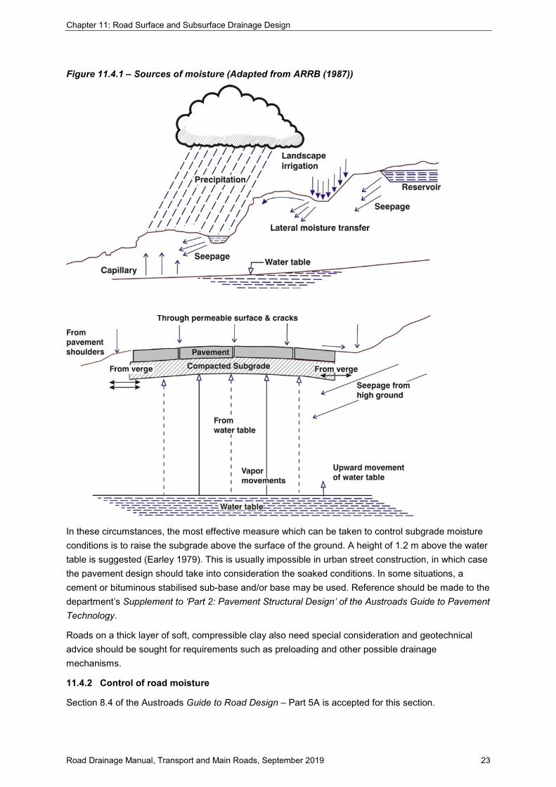
The main mechanisms by which moisture can enter a road subgrade and/or pavement are shown diagrammatically in Figure 11.4.1 and include:
• longitudinal seepage from higher ground, particularly in cuttings and in sag vertical curves
• rise and fall of water table level under a road
• rainfall infiltration through the road surfacing
• capillary moisture from the verges
• capillary water from a water table
• vapour movements from a water table
• lateral movement of moisture from pavement materials comprising the road shoulder
• water flowing or standing in table drains, in catch drains, in median areas, within raised traffic islands or adjacent to the road (not illustrated)
• leakage of water supply and drainage lines (not illustrated)
• passage of water through construction joints in pavements, and back and front of kerb and channel, between old and new pavements and behind bridge abutments (not illustrated).
It is important to note that, in some flood plains and low-lying areas, a permanent, high-level water table may exist. Subsoil drains may be ineffective in such areas, particularly where it is difficult to provide an outlet. In some cases, such drains could act in reverse and provide a means of access for water to the pavement.
Chapter 11: Road Surface and Subsurface Drainage Design
Road Drainage Manual, Transport and Main Roads, September 2019 23
Figure 11.4.1 – Sources of moisture (Adapted from ARRB (1987))
In these circumstances, the most effective measure which can be taken to control subgrade moisture conditions is to raise the subgrade above the surface of the ground. A height of 1.2 m above the water table is suggested (Earley 1979). This is usually impossible in urban street construction, in which case the pavement design should take into consideration the soaked conditions. In some situations, a cement or bituminous stabilised sub-base and/or base may be used. Reference should be made to the department’s Supplement to ‘Part 2: Pavement Structural Design’ of the Austroads Guide to Pavement Technology.
Roads on a thick layer of soft, compressible clay also need special consideration and geotechnical advice should be sought for requirements such as preloading and other possible drainage mechanisms.
11.4.2 Control of road moisture
Section 8.4 of the Austroads Guide to Road Design – Part 5A is accepted for this section.

Chapter 11: Road Surface and Subsurface Drainage Design
Road Drainage Manual, Transport and Main Roads, September 2019 24
11.4.3 Types of subsurface drainage
Section 8.5 of the Austroads Guide to Road Design – Part 5A is accepted for this section subject to the following amendments.
Addition(s)
1. Consideration of the permeability and capillary moisture characteristic of the material surrounding the pavement is a major factor in assessing the need and type of subsurface drainage required.
Suitable drainage systems for various conditions are presented below.
a) Drainage for surface infiltration
Figure 11.4.3(a) illustrates the type of subsoil drainage suitable for a permeable base and surface contained in relatively impermeable material.
Figure 11.4.3(b) illustrates an embankment with the permeable base and surface on a relatively impermeable subgrade. A free draining layer is provided in the shoulders below a low permeability material.
A variation is to carry the full permeable base course over the full width of the shoulders.
b) Groundwater
A static water table may be lowered by using either drainage trenches shown in Figure 11.4.3(c) or a horizontal filter blanket shown in Figure 11.4.3(d).
The horizontal filter blanket will also act as an intercepting barrier for capillary moisture in some situations.
If water flows along an inclined permeable layer, as shown in Figure 11.4.3(e), a trench should be constructed to divert the subsurface flow into a drainage pipe before it can enter the road structure. The trench should be excavated to at least the depth of the permeable strata.
Upward flow from a pervious aquifer is usually controlled by constructing a horizontal filter blanket in the base of the excavation as shown on Figure 11.4.3(f).
Figure 11.4.3(a) – Drainage for surface infiltration with subsoil drains

Chapter 11: Road Surface and Subsurface Drainage Design
Road Drainage Manual, Transport and Main Roads, September 2019 25
Figure 11.4.3(b) – Drainage for surface infiltration with free draining layer
Figure 11.4.3(c) – Drainage trenches to lower water table
Figure 11.4.3(d) – Horizontal filter blanket to lower water table

Chapter 11: Road Surface and Subsurface Drainage Design
Road Drainage Manual, Transport and Main Roads, September 2019 26
Figure 11.4.3(e) – Trenches to intercept flow through an inclined permeable layer
Figure 11.4.3(f) – Permeable filter to lower the effect of head from a permeable aquifer
c) Standard drains
Subsoil drains, described in MRTS03 (TMR 2015b), are shown in Figure 11.4.3(g). The depth of these drains may be increased to suit the particular installation.
Subsurface drain pipes may be surrounded by a single stage filter or by two-stage filters. Filter materials can consist of aggregates (ranging in size from sand to cobble size), geotextiles or combinations of aggregates and geotextiles. The level of filtering will be determined by the prevailing soil types and any environmental requirements on the discharge. In some cases, a second stage filtering may be required and this can take the form of a geotextile wrap either around the pipe or around all the filter material.
A more recent form is the geocomposite edge drain sometimes known as a ‘strip filter’ or ‘fin drain’. These are prefabricated with a polymer core wrapped in a geotextile. They can be installed in much narrower trenches than traditional pipe-based drains.
Chapter 11: Road Surface and Subsurface Drainage Design
Road Drainage Manual, Transport and Main Roads, September 2019 27
Material requirements are contained in MRTS03 Drainage, Retaining Structures and Protective Treatments (TMR 2019a) including those for sheet filter drains, trench backfill, fibre reinforced concrete pipes, corrugated steel pipes, polyvinylchloride pipes, and plastic pipes (perforated and unperforated). See also Section 11.4.4 on filter materials.
The department’s MRTS04 General Earthworks (TMR 2018c) is also relevant.
Figure 11.4.3(h) shows typical subsoil drain outlets and cleanouts in an urban environment. Standard Drawing No. 1116 (TMR) provides further details including treatments for rural environments.
The outlets of subsoil drains discharging into gully pits, manholes, or culvert endwalls are preferred. Outlets discharging to natural surface should be made accessible for maintenance operations and a concrete headwall should be constructed together with a small area concreted or rockpitched around it as shown on the standard drawing. To aid finding the outlet a timber marker post should be maintained.
Accurate records of the position, depth and type of subsoil drains which are installed should be maintained.
Figure 11.4.3(g) – Standard subsoil drains
Notes:
1. Minimum cover for various compactors unless approved otherwise:
Hand held compactors –100 mm
Compactors < 15 tonnes – 200 mm
Compactors > 15 tonnes – 200 mm
2. All dimensions are in millimetres.

Chapter 11: Road Surface and Subsurface Drainage Design
Road Drainage Manual, Transport and Main Roads, September 2019 28
Figure 11.4.3(h) – Subsoil drain outlets and cleanouts
Notes:
The pavement base course may be more permeable than the sub-base.
Relative permeabilities should be considered in locating the drains.
11.4.4 Requirements of filter materials
This section contains extracts from the Guide to the Control of Moisture in Roads (NAASRA 1983) and applies to most drains.
A filter material is required in any permanent subsurface drainage system to prevent fine soil particles from washing into the system. For satisfactory performance, a filter material must be more permeable than the surrounding material but, at the same time, fine enough to keep that material in place.
In addition, the filter should be stable under flow situations and should itself be prevented from washing into perforations or joints in drainage pipes.
These requirements can be satisfied in various ways, usually by either granular materials or synthetic filter fabrics (geotextiles).
Filter materials are not usually necessary in temporary drainage systems or where the surrounding soil is known to be very stable. Examples of stable material are fractured rock, fissured or jointed heavy clays or other weathered materials, and naturally or artificially cemented materials. Care should be taken to determine whether fissured or jointed materials are sufficiently stable under adverse conditions to warrant dispensing with a filter material. Water flowing from joints should be examined

Chapter 11: Road Surface and Subsurface Drainage Design
Road Drainage Manual, Transport and Main Roads, September 2019 29
for suspended particles and the susceptibility of the material to erosion in the disturbed or undisturbed state determined.
MRTS27 Geotextiles (Separation and Filtration) (TMR 2017c) describes the material requirements and work to be carried out for the relevant geotextiles in drains and trenches and drainage blankets, and geotextiles under or within embankments.
The design of granular filter material is described in Subsurface Drainage of Road Structures (ARRB 1987).
11.4.5 Design procedure
Section 8.8.2 of the Austroads Guide to Road Design – Part 5A is accepted for this section.
11.4.6 Location of subsoil drains
Section 8.6 of the Austroads Guide to Road Design – Part 5A is accepted for this section subject to the following amendments.
Addition(s)
1. Figure 11.4.6(a) shows typical locations of subsoil drains in a divided road in a cutting. The width and nature of the median determines the number of subsoil drains required.
Grassed medians can provide a means by which water can enter the pavement or subgrade. Medians should, therefore, be constructed of a material of low permeability (for example, a compacted soil aggregate as recommended for shoulders) except for 100 mm of topsoil to grow grass. Provision of an impermeable membrane under the median should be considered also.
However, where median planting other than grass is required for aesthetic or headlight screening reasons, the low permeability material or impermeable membrane will inhibit growth and should not be used.
Longitudinal subsoil drainage should be provided where there is a possibility of entry of water from grassed medians, or where there is a significant difference in level between roadways, or where permeable subsoil surface strata exists.
Figure 11.4.6(b) shows typical locations of subsoil drains in a low embankment or transition zone from embankment to cut.
Figure 11.4.6(c) shows a typical example in a cutting where subsoil drains are often required.

Chapter 11: Road Surface and Subsurface Drainage Design
Road Drainage Manual, Transport and Main Roads, September 2019 30
Figure 11.4.6(a) – Location of subsoil drains (divided road)
Note:
If invert of median drain is not much lower than pavement layers and/or the possibility of seepage from median back under pavement exists, a subsoil drain should be considered here.
Figure 11.4.6(b) – Subsoil drains – Low embankment or transition from embankment to cut

Chapter 11: Road Surface and Subsurface Drainage Design
Road Drainage Manual, Transport and Main Roads, September 2019 31
Figure 11.4.6(c) – Subsoil drains in cuttings
Chapter 11: Road Surface and Subsurface Drainage Design
Road Drainage Manual, Transport and Main Roads, September 2019 32
Figure 11.4.6(d) – Transverse, strip filter subsurface drain
11.4.7 Transverse subsurface drains
Section 8.6.1 of the Austroads Guide to Road Design – Part 5A is accepted for this section.
11.4.8 Cut-off drains
Section 8.6.3 of the Austroads Guide to Road Design – Part 5A is accepted for this section.
11.4.9 Design of cut-off drains
Section 8.9.5 of the Austroads Guide to Road Design – Part 5A is accepted for this section.
11.4.10 Size of drain
Section 8.7.1 of the Austroads Guide to Road Design – Part 5A is accepted for this section.
11.4.11 Materials
Section 8.7.2 of the Austroads Guide to Road Design – Part 5A is accepted for this section.
11.4.12 Access to subsurface drains
Section 8.7.2 of the Austroads Guide to Road Design – Part 5A is accepted for this section subject to the following amendments.
Addition(s)
1. Figure 11.4.3(h) shows typical subsoil drain outlets and cleanouts in an urban environment. Standard Drawing No. 1116 (TMR) provides further details including treatments for rural environments.
Pits for subsurface drainage should be spaced not further than 150 m apart for ease of inspection and cleaning of the pipes. Maximum spacing between a cleanout and an outlet should generally not exceed 120 m to facilitate inspection and flushing. In cuttings where groundwater is not present, the distance to the outlet of a pavement drain may be much greater, but intermediate pits should generally be placed at a maximum spacing of 120 m.

Chapter 11: Road Surface and Subsurface Drainage Design
Road Drainage Manual, Transport and Main Roads, September 2019 33
Where groundwater occurs in a cutting, the seepage should be conveyed from the subsurface drain into an impervious collector pipe to minimise water penetration of pavement remote from the problem area.
Outlets should be in areas that are easily accessible and, where possible, visible to personnel standing on the road surface. An outlet should not hinder road maintenance activities, such as cleaning unlined table drains or grass cutting.
Outlets should be provided with some form of erosion protection commonly referred to as a splash zone. Typically, this consists of either:
• a masonry or concrete apron, or
• an area of large aggregate to dissipate the outflow energy.
11.4.13 Lowering of ground water table
Section 8.9.1 of the Austroads Guide to Road Design – Part 5A is accepted for this section.
11.4.14 Schilfgaarde’s Method
Section 8.9.2 of the Austroads Guide to Road Design – Part 5A is accepted for this section.
11.4.15 Draining an inclined aquifer
Section 8.9.3 of the Austroads Guide to Road Design – Part 5A is accepted for this section.
11.4.16 Design of a filter blanket to lower a water table
Section 8.9.4 of the Austroads Guide to Road Design – Part 5A is accepted for this section.
11.4.17 Capillary rise in soils
Section 8.9.6 of the Austroads Guide to Road Design – Part 5A is accepted for this section.