Embed Size (px)
Citation preview

INSTRUCTION MANUAL

Contents
3
1. Product Parameter...........................................................................................4
2. Installation........................................................................................................7
3. Control System...............................................................................................13
4. Troubleshoting...............................................................................................17
5. Maintenance & Care......................................................................................19
1.1 Technical Data................................................................................................................4
1.2 Assembly Parts..............................................................................................................5
1.3 Sectional View...............................................................................................................6
2.1 Preparation....................................................................................................................7
2.2 Supporting Profile..........................................................................................................8
2.3 Microcontroller...............................................................................................................9
2.4 Bruthless Motor.............................................................................................................9
2.5 Guide Profile & Carriage..............................................................................................10
2.6 Stopper.........................................................................................................................10
2.7 Door panels..................................................................................................................11
2.8 Toothed Belt & Belt Clamping......................................................................................12
2.9 Guide Roller.................................................................................................................12
3.1 Control Panel...............................................................................................................13
3.2 Function Explaination...................................................................................................13
3.3 Wire Diagram of Motor.................................................................................................14
3.4 Wire Diagram of Remote Controller.............................................................................14
3.5 Wire Diagram of Radar................................................................................................15
3.6 Wire Diagram of Light Barrier......................................................................................15
3.7 Wire Diagram of Electronic Lock.................................................................................16
3.8 Wire Diagram of Interlocking.......................................................................................16
6. . Check up / Brief ing.........................................................................................20

Parameter
Open style Single open Double open
Installation type Surface mounting
Door leaf weight < 250kgs < 200kgs x2
Door leaf width 700-3000mm 800-4000mm
Bruthless motor DC 36V, 85W
Opening speed 15cm/s - 50cm/s
Closing speed 10cm/s - 45cm/s
Hold open time(adjustable) 2-20s
Impact force <100N
Power AC 220V+/-10% , 50/60Hz 10A
Ambient temperature -20℃-+50℃
1. Product parameter
Close force 70N ≥
Relative humidity 65%
1.1 Technical Data
4

1.2 Assembly Parts
3 15 8
7642
NO Name uantityQ
1
2
3
4
5
Profile 1 (4.2m)
(pc)
Bruthless motor 1
Microcntroller 1
Carriage 4
Toothed belt 1 (7m)
Stopper 2
Guide roller 1
Belt clamping 2
6
7
8
5

1.3 Sectional View
Aluminum Frame door
Glass Frameless Door
6

2. Installation
2.1 Preparation
During the planning of the door system, the manufacturer (the person installing the system)
commissioner/facility operator have to perform an individual risk assessment (together). and the
Danger spots at closing edge
Automatic doors might cause hazards by crushing,shearing,
shearing, hitting and drawing-in at the different closing edge
Secondary Main
closing edge closing edge
Depending on the structural conditions, the prevailing door version and the available
safety equipment, residual risks such as crushing and hitting (with a limited force)
cannot be excluded.
Residual risk
7
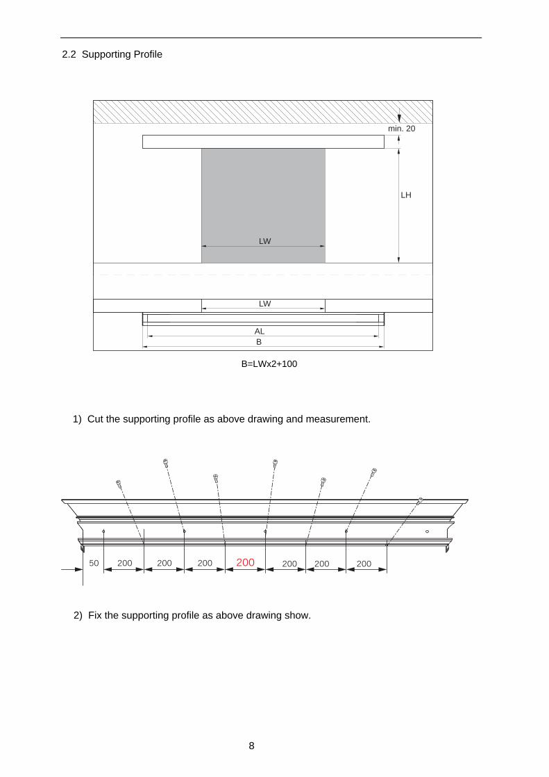
2.2 Supporting Profile
3A
LH
AL
B
LW
min. 20
LW
B=LWx2+100
1) Cut the supporting profile as above drawing and measurement.
50 200 200 200 200 200 200200
2) Fix the supporting profile as above drawing show.
8

2.3 Microcontroller
1) Insert nuts into suporting profile's U-groove.
2) Move microcontroller to profile's left side and fasten microcontroller with Hex SocketBolts and schnorr washers to profile.
Attention,
Before you install all the assembly parts, you should insert all the nuts into
U-groove.
2.4 Bruthless Motor
1) Insert nuts into supporting profile's U-groove.
2) Move the bruthless motor to the right position where the motor wire plug can be
connected with microcontroller.
3) Connect motor with microcontroller by Hex Socket Bolts
Attention,
You should leave a space between motor and microcontroller to install remote
controller.
9

a
2.5 Guide Profile & Carriage
4) Loose the adjusting wheel two bolts (a) and insert it laterlly into the guide profile.
P2001
P2002
P2003
1) Clean the supporting profile's sliding surface(P2001) carefully.
2) Lay out the rubber damping-washer (P2003) onto the slide surface.
3) Lay out the guide profile (P2002) onto the rubber damping-washer.
5) Adjust the andjusting wheel to make the carriage install vertically.
6) then use finger to push the adjusting wheel upward and fasten the two bolts(a) and make sure it can run smoothly.
2.6 Stopper
1) Loose the bolts on the stopper and install the stopper on the guide profile.
3) Fasten the bolts to secure the stopper installation.
Attention,
Incorrect installation may cause damage to the door body.
2) Locate the stopper position by measuring the door full open and closure position.
10
b
c
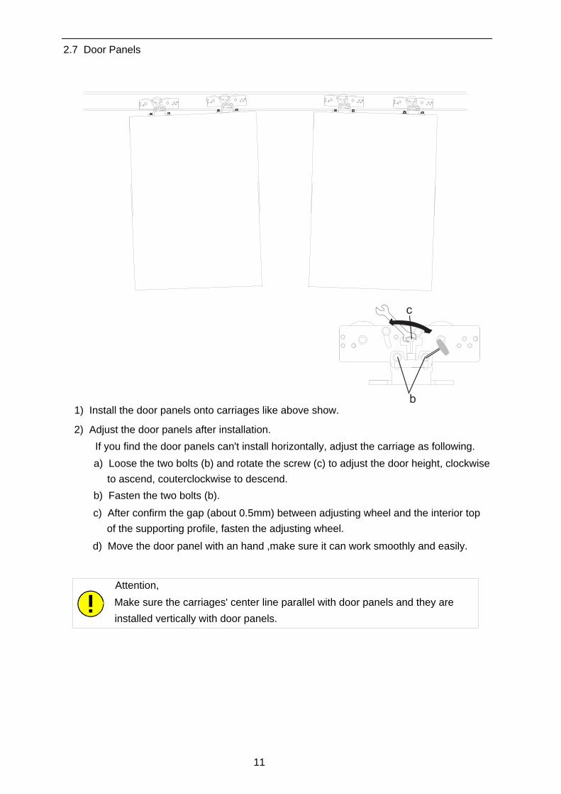
2.7 Door Panels
1) Install the door panels onto carriages like above show.
2) Adjust the door panels after installation.
If you find the door panels can't install horizontally, adjust the carriage as following.
a) Loose the two bolts (b) and rotate the screw (c) to adjust the door height, clockwise
to ascend, couterclockwise to descend.
b) Fasten the two bolts (b).
c) After confirm the gap (about 0.5mm) between adjusting wheel and the interior top
of the supporting profile, fasten the adjusting wheel.
d) Move the door panel with an hand ,make sure it can work smoothly and easily.
Attention,
Make sure the carriages' center line parallel with door panels and they are
installed vertically with door panels.
11

2.8 Toothed Belt & Belt Clamping
1) Remove the bolt (d) and disconnect the belt fixer and belt connecting part.
d
e
2) Cut the belt according to your profile length.
3) Insert the two ends of the belt into the center of the belt fixer crosswise.
4) Connect the belt fixer to belt connecting part and fasten bolt (d).
5) Catch the belt to motor wheel and then the guide roller.
6) Secure the belt clamping to the carriages and fasten the two bolts (e).
Attention,
Don't twist the belt when fixing and make sure all the bolt are fasten tightly
2.9 Guide Roller
1) Push guide roller outward until toothed belt lies flat and tightly.
2) Insert the screw (h) in front of guide roller and fasten it.
3) Use screwdriver,wrench,etc to hold the guide roller until the belt is more tightly, then
fasten the two bolts.
h
g
12

A. Main power terminal
B. Motor terminal
C. Remote controller terminal
D. Inside,outside radar & Light barrier terminal
G. Test button
H. Signal indicator light
K. Working position adjustment switchRP. Working behavior adjustment switch
3. Control System
3.1 Control Panel
A
B
C
DRPKGH
RP1: Opening speed
RP2: Closing speed
RP3: Hold-open time
RP4: Impact force
K1: Battery working option switch
K2: Primary or Secondary induction switchK3: Open direction switch
K4: Door working position when battery initiated
EF
E. Interlocking terminal
F. Battery & E-lock terminal
3.2 Fuction Description
Inside radar Outside Radar Light BarrierBattery&lock Interlocking
36V battery
12V lock
0V 0VH
2
H1
Test B
utton
12V 0V S1
S2
12V 0V S1
S2
12V 0V
LS1
LS2
13

3.3 Wire Diagram of Motor
3.4 Wire Diagram of Remote Controller
Lock Exit only Permanent Open
Half Open Automatic
Attention,
All wire connection should be conducted under power off.
power switch
14

3.5 Wire Diagram of Radar
1234
1234
3.6 Wire Diagram of Light Barrier
receiver1 transmitter1
Radar 1 outside
Radar 2 inside
controlsystem
Attention,
The transmitter and reciver should keep in a line when installating.
15

3.7 Wire Diagram of Electronic Lock
3.8 Wire Diagram of Interlocking
36V UPS
DC12V
-
16

4. Troubleshouting
1. Cut off power
2. Open or close door
manually.
unable to move
with ease
move with ease
power voltage
improper
Door frame area or hanging-up
Check the following items
1) small area(gap between edge frames)
2) if there is garbage in floor guide in the chassis
3) Any garbage in the guide rail.
4)Gapbetweenthestopperandguiderail.
5) Door is twisted and the lock and keyhole condition.
6) Contact with rail cover and building installation.
7) Pulley central line is in parallel with the door.
Check if input power voltage is correct Trouble of input power voltage
1. Switching on power
2. Remove detection signal wire
3. Short-circuit the detection
terminal
Poor contact of parts in the terminal blocks
for controller and motor
1) Sensor disqualified with misoperation
2) detection signal connecting wire
broken or short—circuited.
is
move with ease
Trouble of sensor area
unable to move
with ease
4.1 If the door don't work any more ,please check it as following.
no trouble
17

Malfunctions Causes Checking Remedy
Door moves too slowly or not smoothly
1.Opening/closing speed is too slow 2.Buffer distance value is set too big 3.Somebody ran into the door, or there may be something block inside 4.Too much moving resistance
1.Confirm open-shut speed value 2.Shut the power, push the door and check if there is obstacles hidden inside the alu track
1.Quicken the opening/closing speed 2.Adjust or reset value 3.Close the door for one time 4.Remove the obstacle
Door doesn’t move
1.No power 2.Sensor error 3.Door locked 4.Trash in guide rail 5.Bad wire contact and circuit break
1. Check power switch is on or off 2.If the door is locked. 3.Shut the power and pull or push the door to see if the door can move smoothly 4.Check the wire connection
1.Switch on 2.Replace sensor 3.unlock 4.Remove trash or obstacles 5.Re-connect or replace wire
Door doesn’t shut
1.Sensor keeps activating constantly 2.Safety photo cell keeps activating the door opener 3.Signal line of the sensor short-circuit
1.Moving object stay in the sensor detecting area, or the sensor is in disorder 2.Check if dust covers on the electric eye, or the two cells not in the line
3.Detach the signal line and check if the door begins to close, if yes…
1. Remove the moving object in sensing area, or replace the sensor 2.Clear dust 3. Correct optical axis 4. Replace the signal line
Door automatically opens and shuts without activation
Improper sensor performance
1.If there is moving object inside the detecting area 2.If there is strong electric wave around the door 3.If the detecting area is overlaped by other sensors4.If there is fluorescent lamp in detecting area 5.Poor quality sensor
1.Remove the moving object 2.Removing the source what gives out electric wave 3.Adjust the detecting angle of other sensor 4.Remove fluorescent lamp from detecting area5.Change sensor
Unpleasantreplace or trim screwsoperating noise Screw press against carraige
wheel
4.2 4.2 If faults arise, during learning or operation. Please check the following points:
1) Have all maintenance intervals been observed/has the maintenance been performed?
2) Have all wear parts been checked and replaced if required?
3) Is the power supply connected?
4) Are the areas monitored by the light barriers are clear and clean?
5) Is the door blocked by an obstruction?
6) Is the door running smoothly (adjusting wheel, floor guides) ?
7) Are all external activators, remote controller, lock, photocell connected corretly ?
8) All connection points checked?
For further assistance, consult the following troubleshouting table.
18

5. Care & Maintenance
The unit must be checked and, if necessary, serviced before it is commissioned for the first
time and thereafter as required, but at least once a year by a specialist engineer or by
authorised specialist personnel.
Wear parts
The following wear parts must be checked in regular intervals and replaced if required in order to ensure the smooth function of the unit.
1) Carriage: every 2 years<0095>Rubber end stops: at every service check
3) Track rail: every 5 years4) Toothed belt: every 1,000,000 opening/closingcycle5) Floor guides: at every service check
2) Rubber end stops: at every service check
During cleaning, the remote control must be set to to PERMANT OPEN in order to avoide
inadvertent movements of the door. The whole of the sliding door unit (aluminium, glass,
covers) can be cleaned with a damp cloth and normal commercial detergents. The light
barriers have to be cleaned with a dry cloth and the floor guide rails must be cleaned.
Wear partsCleaning
We recommand to conclude a maintenance contract with your supplier.
The safety sensors (infrared light curtains) are designed to safeguard the passage area.
When it comes to adjusting the sensitivity of the sensors, the protection of people always
has top priority. From time to time, changing climatic conditions (such as rain or snow),
flying leaves or direct sunlight (reflected by certain floor finishes) may accidentally trigger
the sensors. As soon as the light curtains have been triggered, the door may remain open
for up to one minute -- as required by a certain standard. This is o nly a standard procedure
with the only purpose to protect the users of the door system.
Behaviour of door system during varying weather conditions
Only use the original spare parts
19

1) Derailment guard/ counter roller adjusted correctly (0.5 mm)?
2) Door panels run smoothly, no grinding noise?
3) Electromechanical locking adjusted correctly (> 1mm)?
4) All shortened wires provided with end splices?
5) All connectors plugged in?
6) All cables fixed / no obstacles within the driving phase?
7) Serial connection with "internal sensor" performed?
6. . Check up / Brief
Following successful commissioning and functional testing of the unit, the documentation
has to be handed over to the facility operator and a briefing has to be made.
ing
20


![The entity-relationship model : a basis for the enterprise ...€¦ · usedinthispaperistheEntity-Relationship(E-R)model[^,5l« The E-Rmodel and similarapproaches[6,7i8,9] have beenfound](https://img.pdfslide.us/doc/110x75/5ea190ccc4de0538f031c6f1/the-entity-relationship-model-a-basis-for-the-enterprise-usedinthispaperistheentity-relationshipe-rmodel5l.jpg)