Embed Size (px)
Citation preview

User Guide Supplement p. 1 2006-04-18
RMIM Design & RoseTree User Guide for Changes November 2004 through April 2006
1 Introduction................................................................................................................. 1 1.1 Creation and use of "local" CMETs.................................................................... 1 1.2 Changes in the handling of "formal naming" and "stubs" .................................. 1 1.3 Batch Process for Creating Clickable Grphics.................................................... 2
2 Defining & Using "local" CMETs.............................................................................. 2 2.1 Determining the CMET name, identifier and related information ..................... 2 2.2 CMET reference for use by RMIM Designer ..................................................... 3 2.3 Adding your CMET design to repository ........................................................... 5
3 Software Installation and Naming Source File ........................................................... 8 3.1 Binding to RMIM Designer ................................................................................ 9 3.2 Changing source data file.................................................................................... 9
4 Designating Class Clones as "Stub" classes ............................................................... 9 4.1 Qualifications for a stub class ........................................................................... 10 4.2 Making the change in Visio .............................................................................. 10 4.3 Seeing/making change in RoseTree RMIM view............................................. 12 4.4 Effect on RoseTree HMD view ........................................................................ 13 4.5 Changes to "*.hmd" output file......................................................................... 14
5 Batch Creation of Clickable Graphics ...................................................................... 15 5.1 Installing RMIM Designer in Visio .................................................................. 15 5.2 File Structure for Batch Graphics Creation ...................................................... 18 5.3 Running the Batch Process ............................................................................... 19
1 Introduction Over several months, changes have been made to the tools that are not discussed in the User Guide. This document provides a brief supplement to the User Guide that addresses the changes the following changes.
1.1 Creation and use of "local" CMETs The process of creating and using "local" CMETs in HL7 RMIM designs and involves three steps – (1) deciding upon the name, message type identifier, and related information for your local CMET; (2) providing a reference in a “local” CMETinfo.txt file that the RMIM designer in Visio can use to place CMETs in your RMIM design; and (3) actually creating a CMET definition in your design repository that can then be included in the schemas for your designs. These second and third steps can be performed in either order, but the second step is all that is necessary to include the CMET definition in your other RMIM designs. These three steps are considered in detail below.
1.2 Changes in the handling of "formal naming" and "stubs" Tooling changes introduced early in November 2004 targeted anomalies that were causing the schema generator to fail when dealing with CMET bindings. As a result,
• The automatic naming was fixed to handle Role-based CMETs correctly. • Formal naming was moved to a separate process to allow sharing of code with
other programs and the sorting of associations was placed in the same package.
User Guide Supplement p. 2 2006-04-18
• Modifications were made to allow the designation of "stub" classes – those classes which designate the point at which to include a payload within a wrapper.
These changes are discussed below.
1.3 Batch Process for Creating Clickable Grphics The RMIM Designer has a batch process for creating clickable graphics (graphic with a matching HTML map) of HL7 Visio Designs. The resulting graphics are programmed to hyper-link to Table Views created with the V3Generator. This section includes notes and screen shots to guide one through the process, starting with installation.
2 Defining & Using "local" CMETs
2.1 Determining the CMET name, identifier and related information
In order to define a "local" CMET, the designer must first determine its defining properties. The complete data set necessary to define a CMET includes six elements of information. These elements are defined further below, along with an example be drawn from one of the standard HL7 CMET's for a patient encounter.
2.1.1 name By custom, the name is structured according to the root class of the CMET being defined. Thus, if the CMET has the Act class as its root, the name should begin with “A_”. Similarly, if it has either the Role or the Entity class as its root, then the name should begin with either “R_” or “E_”. The remainder of the name is a standard upper-CamelCase name for the root class. For example: “A_Encounter”
2.1.2 artifactId The identifier should be drawn from the identifier "namespace" for the chapter in which the local CMET will be used. Thus, if the CMET is being generated for Patient Administration, then the identifier should begin with “PRPA_”, followed by a proper message type identifier, an example of a local CMET identifier might be “PRPA_123654”. The example for the “A_Encounter CMET is “COCT_MT010000”.
2.1.3 classCode The next element to be defined is the actual class code for the entry (starting) class of your design. Needless to say, this class code must be drawn from the appropriate hierarchy for the root class. The example for "A_Encounter" is: “ENC”
2.1.4 rootClass The third element is the name of the root class itself. For CMET's that represent structures , whose root is either Act, or Entity, the name of the root class is sufficient. However, for CMET's that are drawn from the Role class, it is also necessary to indicate the function that the CMET can play within a given design. The three choices for roles are:

User Guide Supplement p. 3 2006-04-18
Role(Performed only) - which is used for CMET's that can only be linked to a Participation. That is, the entry of the CMET occurs only while transiting from an Act through a Participation to a Role (the CMET).
Role(Played or Performed) - which is used for CMET's that can be linked either through a Participation, or through the relationship from an Entity that plays the Role.
Role(Scoped or Performed) - which is used for CMET's that are not linked through a participation, but may be linked through either of the two relationships between an Entity and a Role -- the scoping and playing relationships.
In our example, this would be: "Act"
2.1.5 description The fourth element is a brief description of the CMET , which will appear in the RMIM designer dialog box to guide users who are selecting among the available CMETs. The example from the standard CMET file is: "Used to refer to an encounter:
2.1.6 attributionLevel The final element is the attribution level of the CMET attribution levels are defined in a hierarchy that begins with "universal", the most general form of CMET. Other levels of attribution it had been used in the standard CMET file include: identified, minimal, contact, etc. For the example "A_Encounter" CMET, the value is: “universal”
2.2 CMET reference for use by RMIM Designer
2.2.1 Creating reference file In order to be able to use a local a defined CMET in RMIM designs, it is necessary to place a reference for the CMET in a file that the RMIM designer uses to assemble the complete list of available CMET. The base file for this purpose , is held in the Visio solutions directory , which is usually "C:\Program Files\Microsoft Office\Visio10\1033\Solutions\HL7". This is the directory in which the RMIM designer was placed when it was installed. The file name for the base file is CMETInfo.txt. In order to create a reference for local CMET use, one creates a copy of this base file that contains only the newly-defined, local CMET(s) and places this local file in the same directory as the designs being built. The steps, therefore, are as follows:
1. Make a copy of the base "CMETInfo.txt" file. The contents of this file to look like:
name,artifactId,classCode,rootClass,description,attributionLevel A_Encounter,COCT_MT010000,ENC,Act,Used to refer to an encounter,universal A_Encounter,COCT_MT010001,ENC,Act,Used to refer to an encounter,identified A_Encounter,COCT_MT010004,ENC,Act,Used to refer to an encounter,minimal ...
This file is a simple comma-delimited file with six data elements per row. The first row of the file includes the names of the data fields in each of the following rooms. Thus the sequence of a data definition is the same as was used in the section preceding.
2. Edit the file so as to remove the existing CMET definitions, but leave the row with the field names.

User Guide Supplement p. 4 2006-04-18
3. Add to one or more rows with the data for the local CMET's you wish to define. An example of such as CMET definition file for local CMET's might look like the following:
name,artifactId,classCode,rootClass,description,attributionLevel A_LocalEncounter,PRPA_MT654123,ENC,Act,A local encounter,universal R_LocalPatient,PRPA_MT654124,PAT,Role(Performed only),"Local PAT",universal
4. Save this new file with the same name,"CMETinfo.txt", in the directory you are using to save your Visio designs. That is, in the directory where you're "*.vsd" files are being stored.
This completes the creation of the reference file that holds definitions for your local CMET's.
2.2.2 Using local CMET reference file in Visio The next remaining step is to get the Visio RMIM designer to load this file, and thereby to recognize your new CMET's. Assuming that you are working on a Visio drawing that is saved in the same directory as you just placed your local CMETinfo.txt file, the following steps will “pick up” this reference file in Visio.
1. Proceed with the design up to the point where you need the first local CMET. When you “drop” the CMET, the following dialog appears.
2. When the dialog box appears, click the “Refresh” button. This causes the local CMET reference file to be added to the standard references.
User Guide Supplement p. 5 2006-04-18
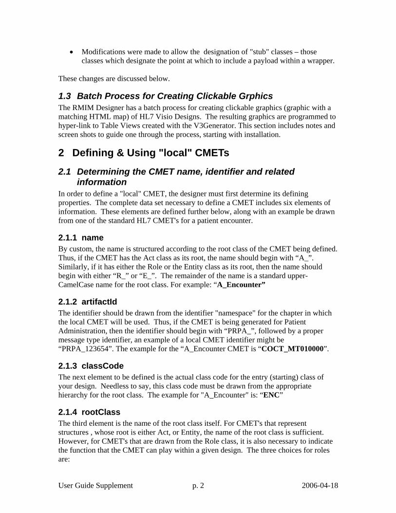
3. With your local CMET listed, it is available for selection, as at right.
4. As a result, your local CMETs will appear as options in the list, allowing their addition to your designs, as at right.
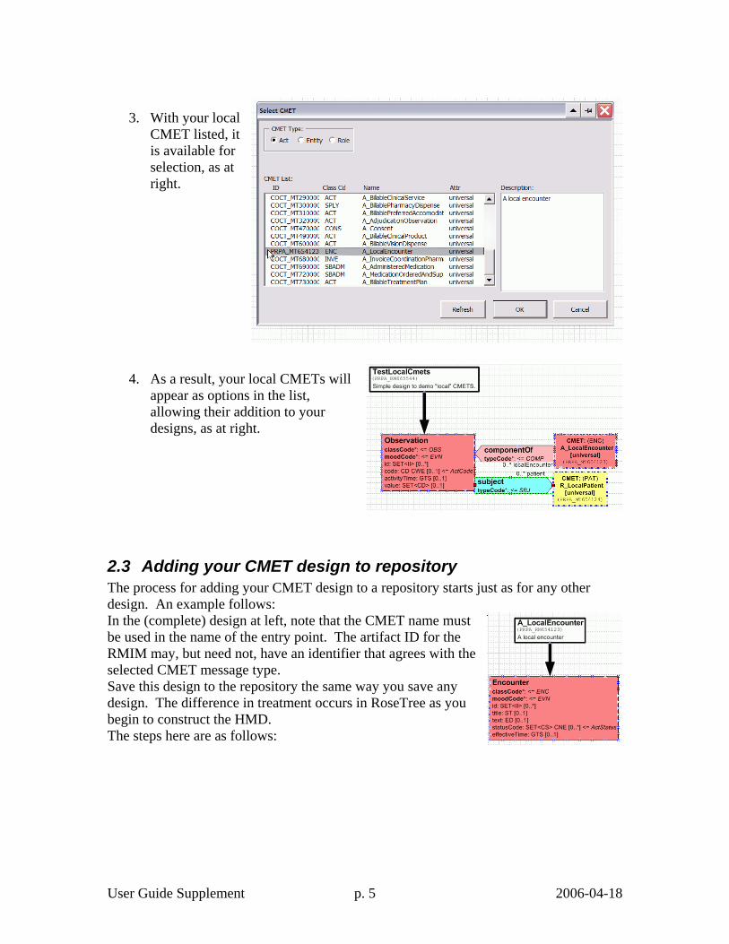
2.3 Adding your CMET design to repository The process for adding your CMET design to a repository starts just as for any other design. An example follows: In the (complete) design at left, note that the CMET name must be used in the name of the entry point. The artifact ID for the RMIM may, but need not, have an identifier that agrees with the selected CMET message type. Save this design to the repository the same way you save any design. The difference in treatment occurs in RoseTree as you begin to construct the HMD. The steps here are as follows:
User Guide Supplement p. 6 2006-04-18
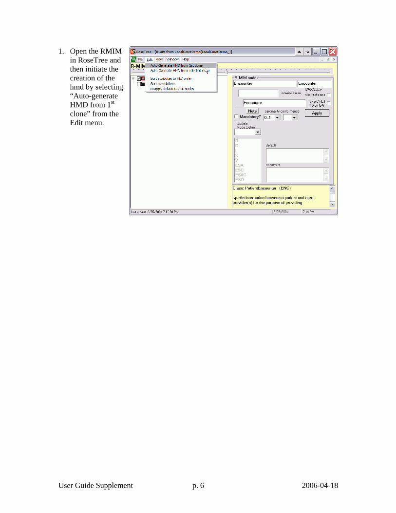
1. Open the RMIM in RoseTree and then initiate the creation of the hmd by selecting “Auto-generate HMD from 1st clone” from the Edit menu.
User Guide Supplement p. 7 2006-04-18
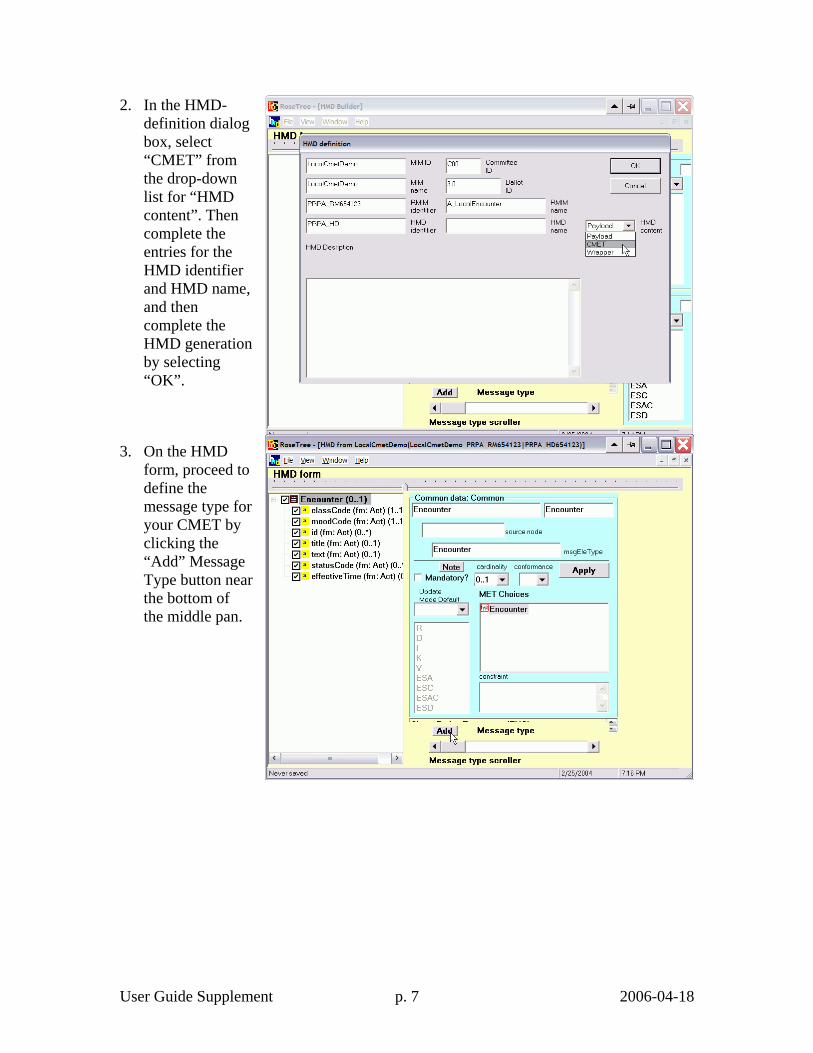
2. In the HMD-definition dialog box, select “CMET” from the drop-down list for “HMD content”. Then complete the entries for the HMD identifier and HMD name, and then complete the HMD generation by selecting “OK”.
3. On the HMD form, proceed to define the message type for your CMET by clicking the “Add” Message Type button near the bottom of the middle pan.
User Guide Supplement p. 8 2006-04-18
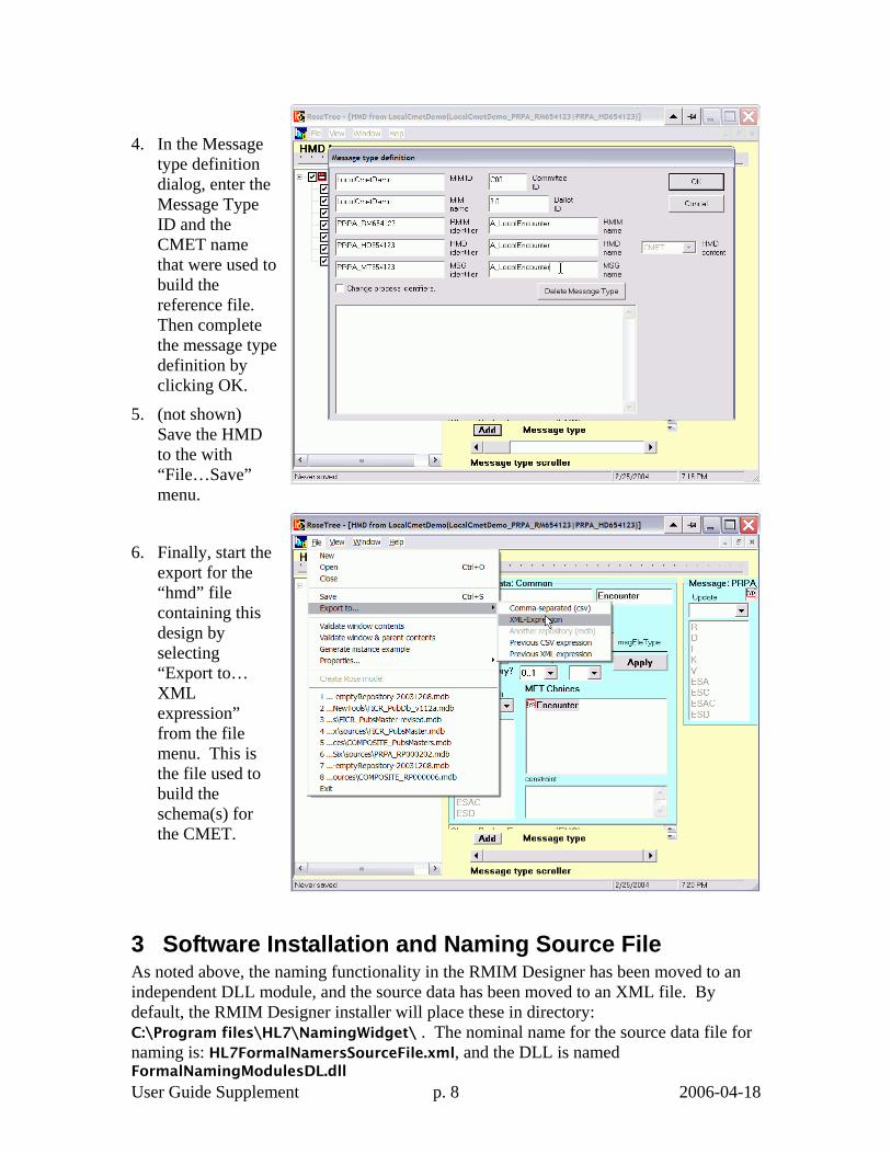
4. In the Message type definition dialog, enter the Message Type ID and the CMET name that were used to build the reference file. Then complete the message type definition by clicking OK.
5. (not shown) Save the HMD to the with “File…Save” menu.
6. Finally, start the export for the “hmd” file containing this design by selecting “Export to… XML expression” from the file menu. This is the file used to build the schema(s) for the CMET.
3 Software Installation and Naming Source File As noted above, the naming functionality in the RMIM Designer has been moved to an independent DLL module, and the source data has been moved to an XML file. By default, the RMIM Designer installer will place these in directory: C:\Program files\HL7\NamingWidget\ . The nominal name for the source data file for naming is: HL7FormalNamersSourceFile.xml, and the DLL is named FormalNamingModulesDL.dll

User Guide Supplement p. 9 2006-04-18
3.1 Binding to RMIM Designer The DLL is "registered" as it installs, so the RMIM Designer (Visio) should bind to it automatically. When the naming software is started, it looks for the source file by its default name in the same directory as the DLL (default location). Should it fail to find the file there, and if there is no file location saved in the registry (see below), it will prompt with a dialog as shown in the figure on the following page. Note that although the dialog lists a file name, the fact that the "OK" button is not enabled indicates that there is no such file on the system. You can enter a file name as text, or use the "Browse" button to find the file.
Figure 1 Dialog to find source data file for Formal Naming. Once a file has been found, the program will save the file location in the registry for use the next time the programs are started. If the proper file is not found, the program will proceed, but will eventually either ask again, or present an error message like the following (the message may appear several times in sequence):
Figure 2 Error message if no naming source data file is provided.
3.2 Changing source data file At times, the toolsmiths will release an updated data file to drive the formal naming. The source file can be changed no additional software installation. The easiest was is to simply replace the original file with the new one. Note that you cannot leave the original file in place, as the software will continue to use the old file so long as it can find it at the location the program saved in the registry.
4 Designating Class Clones as "Stub" classes As noted in the Introduction, "stub" classes are those classes placed in an RMIM design that designate the place where included data structures, like CMETs are to be bound into the design. The RMIM design tool uses the CMET shape to designate stubs for CMETs, but does not have a particular shape to use for designating the stubs that are the point at which other wrappers or payloads are bound into the design for an "outer" wrapper.
User Guide Supplement p. 10 2006-04-18
Future release of the RMIM Designer tool will provide a specific shape (or a variant of the CMET shape) for this purpose. In the meantime, the current (11/11/2004) release provides a menu-driven mechanism for designating an ordinary class clone as a stub.
4.1 Qualifications for a stub class In order to be used as a stub class, the class clone must meet the following criteria:
• The class must be a clone of Act, Role, Entity or one of the "Other" classes (for stubs such as Queries).
• Must no attributes other than the structural attributes (if any) such as typeCode, classCode, moodCode, and/or determinerCode.
• All structural attributes for the class must be included. • Although a stub typically has a single association leading into it, it may have
several paths into it, but all outbound paths must be blocked. • The stub classes should not be members of a Choice box, nor should they be
shadowed. The implementation has not been tested for such arrangements.
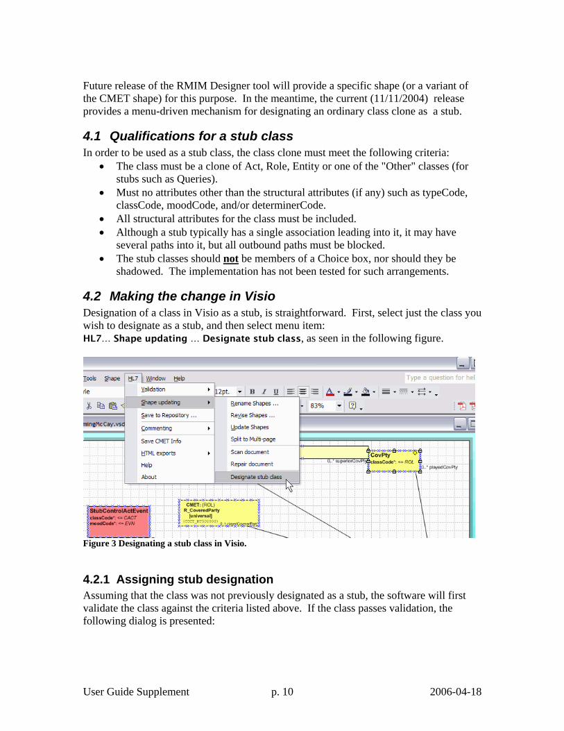
4.2 Making the change in Visio Designation of a class in Visio as a stub, is straightforward. First, select just the class you wish to designate as a stub, and then select menu item: HL7… Shape updating … Designate stub class, as seen in the following figure.
Figure 3 Designating a stub class in Visio.
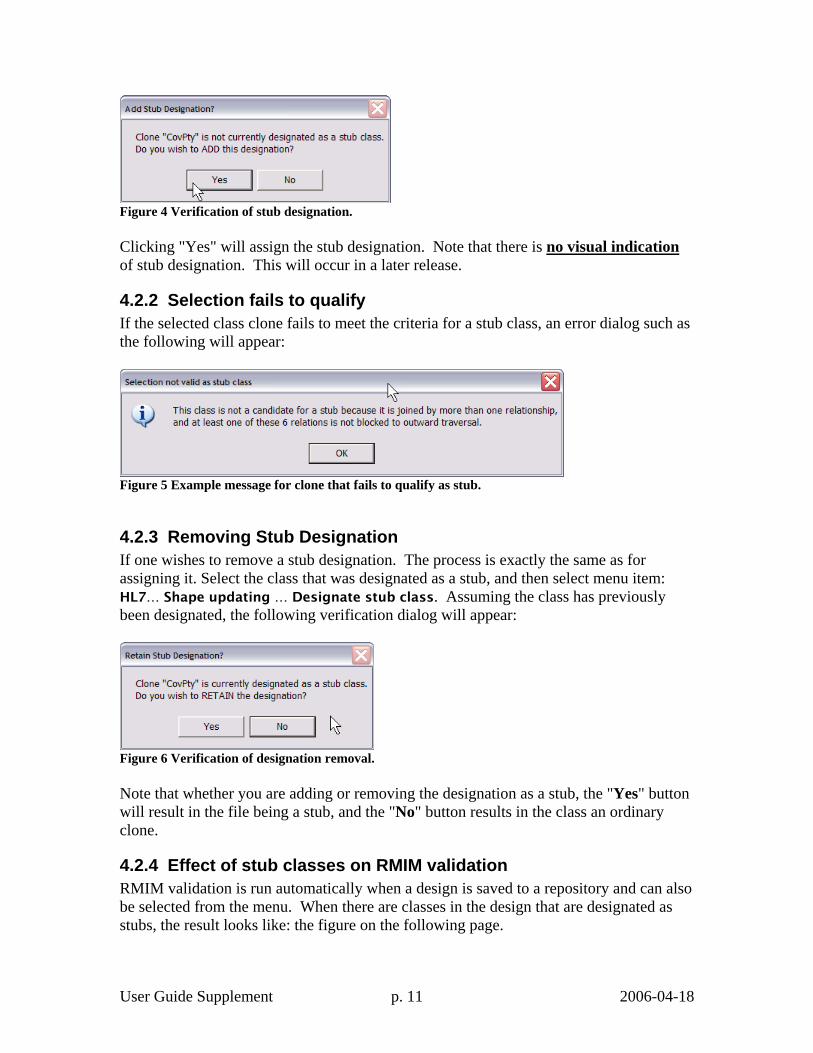
4.2.1 Assigning stub designation Assuming that the class was not previously designated as a stub, the software will first validate the class against the criteria listed above. If the class passes validation, the following dialog is presented:
User Guide Supplement p. 11 2006-04-18
Figure 4 Verification of stub designation. Clicking "Yes" will assign the stub designation. Note that there is no visual indication of stub designation. This will occur in a later release.
4.2.2 Selection fails to qualify If the selected class clone fails to meet the criteria for a stub class, an error dialog such as the following will appear:
Figure 5 Example message for clone that fails to qualify as stub.
4.2.3 Removing Stub Designation If one wishes to remove a stub designation. The process is exactly the same as for assigning it. Select the class that was designated as a stub, and then select menu item: HL7… Shape updating … Designate stub class. Assuming the class has previously been designated, the following verification dialog will appear:
Figure 6 Verification of designation removal. Note that whether you are adding or removing the designation as a stub, the "Yes" button will result in the file being a stub, and the "No" button results in the class an ordinary clone.
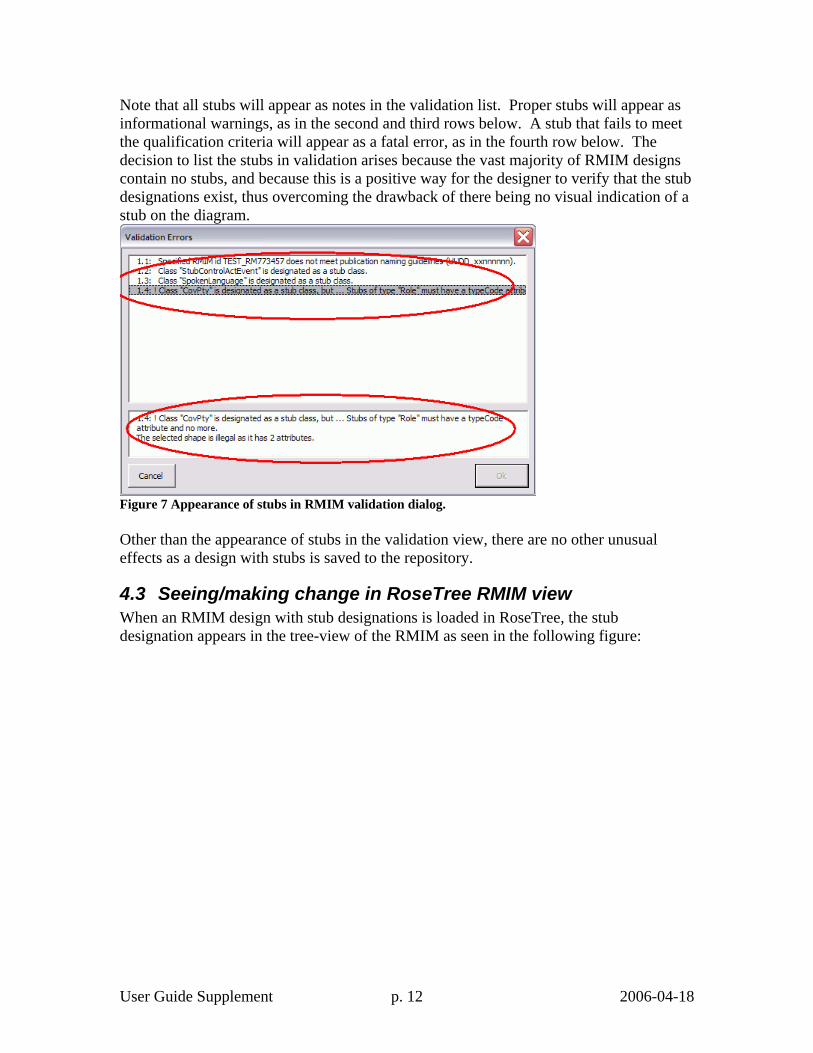
4.2.4 Effect of stub classes on RMIM validation RMIM validation is run automatically when a design is saved to a repository and can also be selected from the menu. When there are classes in the design that are designated as stubs, the result looks like: the figure on the following page.
User Guide Supplement p. 12 2006-04-18
Note that all stubs will appear as notes in the validation list. Proper stubs will appear as informational warnings, as in the second and third rows below. A stub that fails to meet the qualification criteria will appear as a fatal error, as in the fourth row below. The decision to list the stubs in validation arises because the vast majority of RMIM designs contain no stubs, and because this is a positive way for the designer to verify that the stub designations exist, thus overcoming the drawback of there being no visual indication of a stub on the diagram.
Figure 7 Appearance of stubs in RMIM validation dialog. Other than the appearance of stubs in the validation view, there are no other unusual effects as a design with stubs is saved to the repository.
4.3 Seeing/making change in RoseTree RMIM view When an RMIM design with stub designations is loaded in RoseTree, the stub designation appears in the tree-view of the RMIM as seen in the following figure:
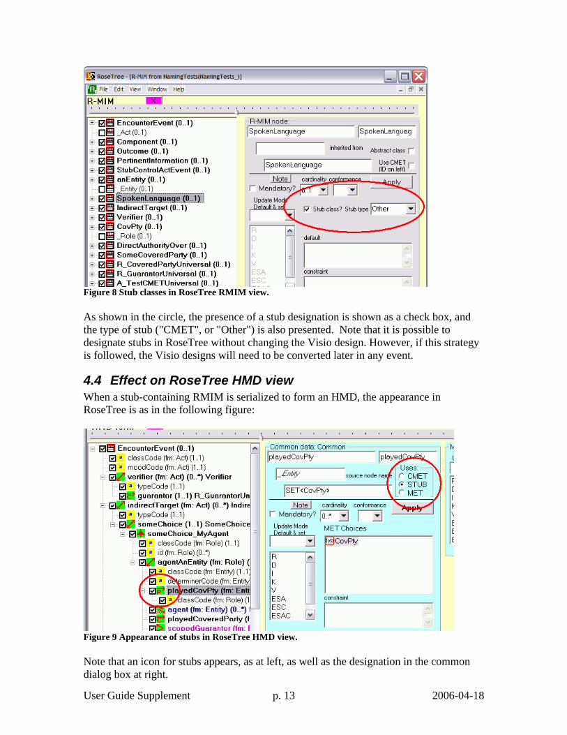
User Guide Supplement p. 13 2006-04-18
Figure 8 Stub classes in RoseTree RMIM view. As shown in the circle, the presence of a stub designation is shown as a check box, and the type of stub ("CMET", or "Other") is also presented. Note that it is possible to designate stubs in RoseTree without changing the Visio design. However, if this strategy is followed, the Visio designs will need to be converted later in any event.
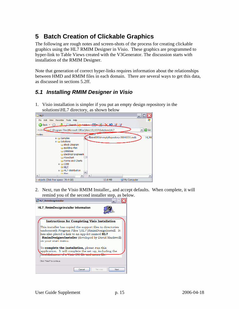
4.4 Effect on RoseTree HMD view When a stub-containing RMIM is serialized to form an HMD, the appearance in RoseTree is as in the following figure:
Figure 9 Appearance of stubs in RoseTree HMD view. Note that an icon for stubs appears, as at left, as well as the designation in the common dialog box at right.

User Guide Supplement p. 14 2006-04-18
4.5 Changes to "*.hmd" output file The result of these code changes appear in the HMD file used to build schemas. Two changes occur, as seen in the following screen shot of an HMD file in XML-Spy. Each element that represents an attribute or association row in an HMD now includes the "SortKey" attribute that determines the ordering of these elements when an HMD is serialized. Stub classes that are not CMETs are shown as associations in which the "Assoc.ofMETtype.MET" element has its "source" attribute set as "S". (In a similar fashion, the same attribute in a CMET row is valued with "C".)
Figure 10-Fragment of HMD file that includes stubs.
User Guide Supplement p. 15 2006-04-18
5 Batch Creation of Clickable Graphics The following are rough notes and screen-shots of the process for creating clickable graphics using the HL7 RMIM Designer in Visio. These graphics are programmed to hyper-link to Table Views created with the V3Generator. The discussion starts with installation of the RMIM Designer. Note that generation of correct hyper-links requires information about the relationships between HMD and RMIM files in each domain. There are several ways to get this data, as discussed in sections 5.2ff.
5.1 Installing RMIM Designer in Visio 1. Visio installation is simpler if you put an empty design repository in the
solutions\HL7 directory, as shown below
2. Next, run the Visio RMIM Installer,, and accept defaults. When complete, it will remind you of the second installer step, as below.
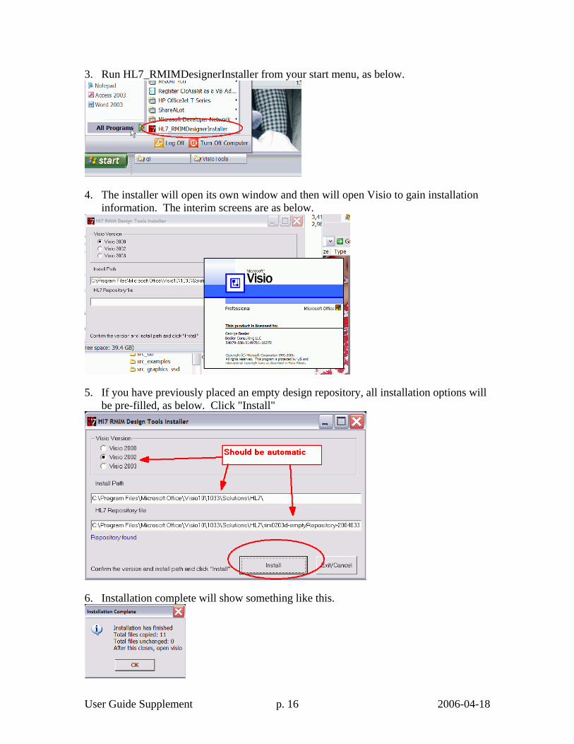
User Guide Supplement p. 16 2006-04-18
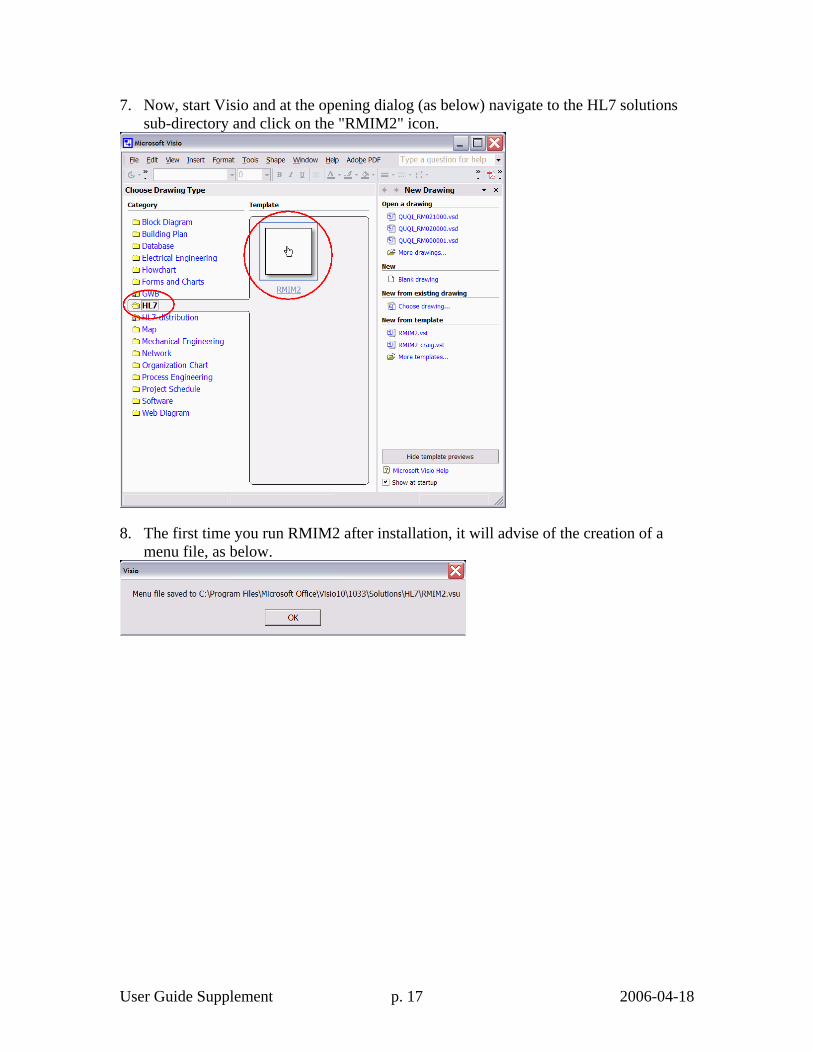
3. Run HL7_RMIMDesignerInstaller from your start menu, as below.
4. The installer will open its own window and then will open Visio to gain installation information. The interim screens are as below.
5. If you have previously placed an empty design repository, all installation options will be pre-filled, as below. Click "Install"
6. Installation complete will show something like this.
User Guide Supplement p. 17 2006-04-18
7. Now, start Visio and at the opening dialog (as below) navigate to the HL7 solutions sub-directory and click on the "RMIM2" icon.
8. The first time you run RMIM2 after installation, it will advise of the creation of a menu file, as below.
User Guide Supplement p. 18 2006-04-18
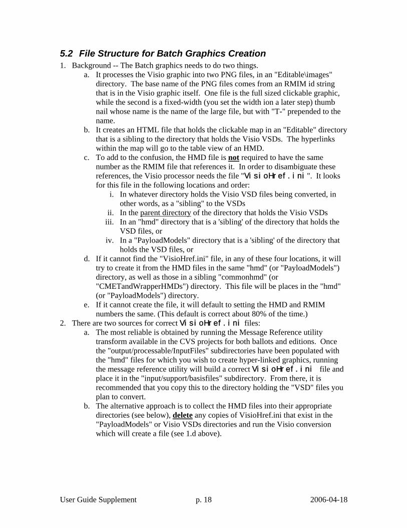
5.2 File Structure for Batch Graphics Creation 1. Background -- The Batch graphics needs to do two things.
a. It processes the Visio graphic into two PNG files, in an "Editable\images" directory. The base name of the PNG files comes from an RMIM id string that is in the Visio graphic itself. One file is the full sized clickable graphic, while the second is a fixed-width (you set the width ion a later step) thumb nail whose name is the name of the large file, but with "T-" prepended to the name.
b. It creates an HTML file that holds the clickable map in an "Editable" directory that is a sibling to the directory that holds the Visio VSDs. The hyperlinks within the map will go to the table view of an HMD.
c. To add to the confusion, the HMD file is not required to have the same number as the RMIM file that references it. In order to disambiguate these references, the Visio processor needs the file "VisioHref.ini". It looks for this file in the following locations and order:
i. In whatever directory holds the Visio VSD files being converted, in other words, as a "sibling" to the VSDs
ii. In the parent directory of the directory that holds the Visio VSDs iii. In an "hmd" directory that is a 'sibling' of the directory that holds the
VSD files, or iv. In a "PayloadModels" directory that is a 'sibling' of the directory that
holds the VSD files, or d. If it cannot find the "VisioHref.ini" file, in any of these four locations, it will
try to create it from the HMD files in the same "hmd" (or "PayloadModels") directory, as well as those in a sibling "commonhmd" (or "CMETandWrapperHMDs") directory. This file will be places in the "hmd" (or "PayloadModels") directory.
e. If it cannot create the file, it will default to setting the HMD and RMIM numbers the same. (This default is correct about 80% of the time.)
2. There are two sources for correct VisioHref.ini files: a. The most reliable is obtained by running the Message Reference utility
transform available in the CVS projects for both ballots and editions. Once the "output/processable/InputFiles" subdirectories have been populated with the "hmd" files for which you wish to create hyper-linked graphics, running the message reference utility will build a correct VisioHref.ini file and place it in the "input/support/basisfiles" subdirectory. From there, it is recommended that you copy this to the directory holding the "VSD" files you plan to convert.
b. The alternative approach is to collect the HMD files into their appropriate directories (see below), delete any copies of VisioHref.ini that exist in the "PayloadModels" or Visio VSDs directories and run the Visio conversion which will create a file (see 1.d above).
User Guide Supplement p. 19 2006-04-18
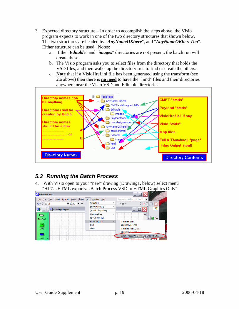
3. Expected directory structure – In order to accomplish the steps above, the Visio program expects to work in one of the two directory structures that shown below. The two structures are headed by "AnyNameOKhere", and "AnyNameOKhereToo". Either structure can be used. Notes:
a. If the "Editable" and "images" directories are not present, the batch run will create these.
b. The Visio program asks you to select files from the directory that holds the VSD files, and then walks up the directory tree to find or create the others.
c. Note that if a VisioHref.ini file has been generated using the transform (see 2.a above) then there is no need to have the "hmd" files and their directories anywhere near the Visio VSD and Editable directories.
5.3 Running the Batch Process 4. With Visio open to your "new" drawing (Drawing1, below) select menu
"HL7…HTML exports…Batch Process VSD to HTML Graphics Only"

User Guide Supplement p. 20 2006-04-18
5. The next dialog allows you to select the width of the thumb nails before you verify your desire to do a batch conversion by clicking "Export HTML Graphics" (see figure below). I recommend a scaling more in the 250-300 range to balance visible content with space consumed on the HTML rendition. In any case, Helen Stevens should have the last say.
6. In the following file selection box, navigate to the source directory. and select one, more or all of the VSD files; then click "Open"
User Guide Supplement p. 21 2006-04-18
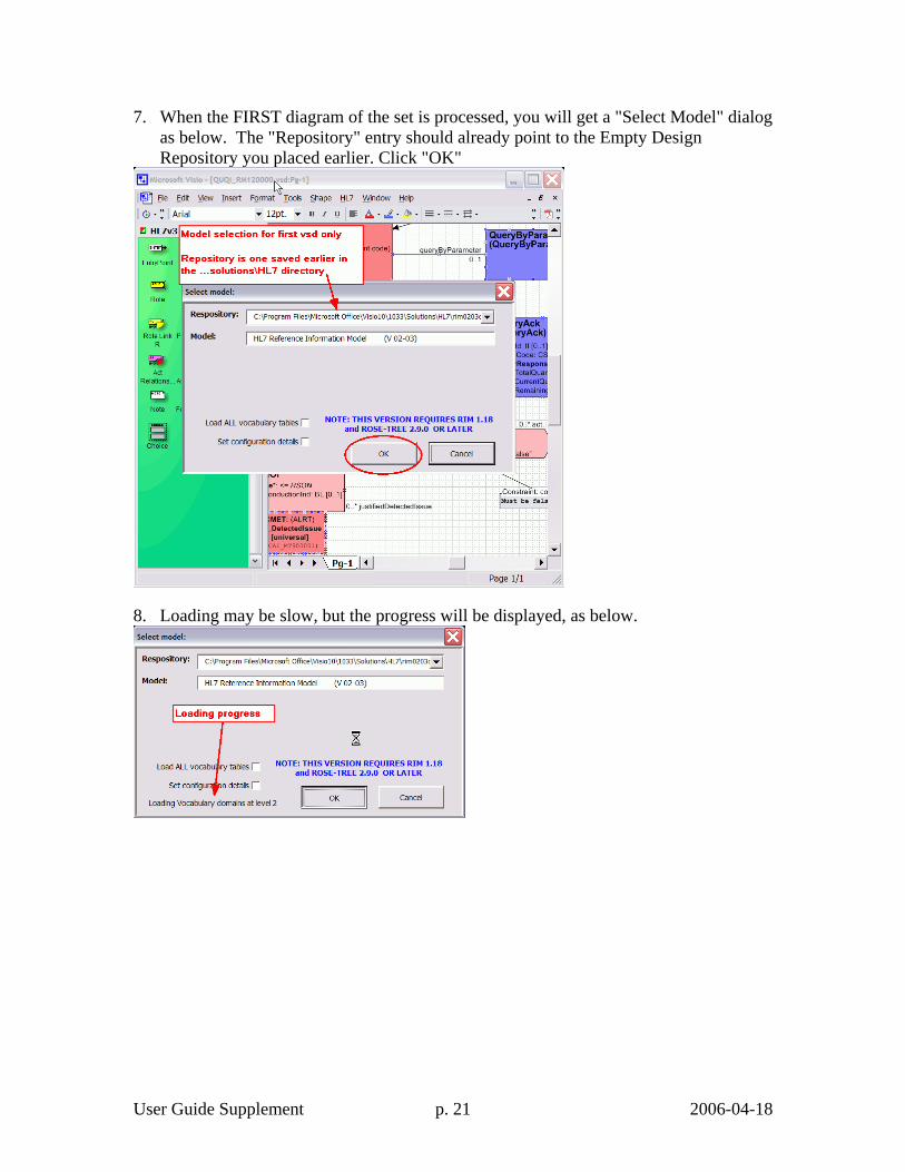
7. When the FIRST diagram of the set is processed, you will get a "Select Model" dialog as below. The "Repository" entry should already point to the Empty Design Repository you placed earlier. Click "OK"
8. Loading may be slow, but the progress will be displayed, as below.

User Guide Supplement p. 22 2006-04-18
9. Once the actual conversion starts, the main panel will switch around a lot, but the batch dialog will show which file is being processed at each stage, as below.
10. Completion of graphics export is reported, as below.
11. Close Visio, and when asked to save changes to your "drawing", Click "No" as below.