Embed Size (px)
Citation preview
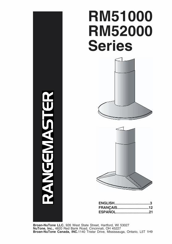
RM51000RM52000Series
Broan-NuTone LLC. 926 West State Street, Hartford, WI 53027NuTone, Inc., 4820 Red Bank Road, Cincinnati, OH 45227Broan-NuTone Canada, INC.1140 Tristar Drive, Mississauga, Ontario, L5T 1H9
ENGLISH......................................3FRANÇAIS.................................12ESPAÑOL...................................21

- 3 -
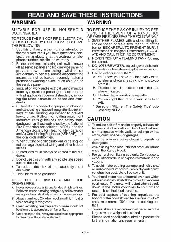
READ AND SAVE THESE INSTRUCTIONSWARNINGSUITABLE FOR USE IN HOUSEHOLDCOOKING AREA.
TO REDUCE THE RISK OF FIRE, ELECTRICALSHOCK, OR INJURY TO PERSONS, OBSERVETHE FOLLOWING:1. Use this unit only in the manner intended by
the manufacturer. If you have questions, con-tact the manufacturer at the address or tele-phone number listed in the warranty.
2. Before servicing or cleaning unit, switch poweroff at service panel and lock service panel toprevent power from being switched onaccidentally. When the service disconnectingmeans cannot be locked, securely fasten aprominent warning device, such as a tag, tothe service panel.
3. Installation work and electrical wiring must bedone by a qualified person(s) in accordancewith all applicable codes and standards, includ-ing fire-rated construction codes and stan-dards.
4. Sufficient air is needed for proper combustionand exhausting of gases through the flue (chim-ney) of fuel burning equipment to preventbackdrafting. Follow the heating equipmentmanufacturer’s guidelines and safety stan-dards such as those published by the NationalFire Protection Association (NFPA), and theAmerican Society for Heating, Refrigerationand Air Conditioning Engineers (ASHRAE), andthe local code authorities.
5. When cutting or drilling into wall or ceiling, donot damage electrical wiring and other hiddenutilities.
6. Ducted fans must always be vented to the out-doors.
7. Do not use this unit with any solid-state speedcontrol device.
8. To reduce the risk of fire, use only steelductwork.
9. This unit must be grounded.
TO REDUCE THE RISK OF A RANGE TOPGREASE FIRE:A. Never leave surface units unattended at high settings.
Boilovers cause smoking and greasy spillovers thatmay ignite. Heat oils slowly on low or medium settings.
B. Always turn hood ON when cooking at high heat orwhen cooking flaming foods.
C. Clean ventilating fans frequently. Grease should notbe allowed to accumulate on fan or filter.
D. Use proper pan size. Always use cookware appropriatefor the size of the surface element.
WARNINGTO REDUCE THE RISK OF INJURY TO PER-SONS IN THE EVENT OF A RANGE TOPGREASE FIRE, OBSERVE THE FOLLOWING:*1. SMOTHER FLAMES with a close-fitting lid,
cookie sheet, or metal tray, then turn off theburner. BE CAREFUL TO PREVENT BURNS.If the flames do not go out immediately, EVACU-ATE AND CALL THE FIRE DEPARTMENT.
2. NEVER PICK UP A FLAMING PAN - You maybe burned.
3. DO NOT USE WATER, including wet dishclothsor towels - violent steam explosion will result.
4. Use an extinguisher ONLY if:A. You know you have a Class ABC extin-
guisher and you already know how to op-erate it.
B. The fire is small and contained in the areawhere it started.
C. The fire department is being called.D. You can fight the fire with your back to an
exit.* Based on “Kitchen Fire Safety Tips” pub-
lished by NFPA.
CAUTION1. To reduce risk of fire and to properly exhaust air,
be sure to duct air outside. Do not vent exhaustair into spaces within walls or ceilings or intoattics, crawl spaces, or garages.
2. Take care when using cleaning agents ordetergents.
3. Avoid using food products that produce flamesunder the Range Hood.
4. For general ventilating use only. Do not use toexhaust hazardous or explosive materials andvapors.
5. To avoid motor bearing damage and noisy and/or unbalanced impellers, keep drywall spray,construction dust, etc. off power unit.
6. Your hood motor has a thermal overload whichwill automatically shut off the motor if it becomesoverheated. The motor will restart when it coolsdown. If the motor continues to shut off andrestart, have the hood serviced.
7. For best capture of cooking impurities, thebottom of the hood should be a minimum of 24"and a maximum of 30" above the cooking sur-face.
8. Two installers are recommended because of thelarge size and weight of this hood.
9. Please read specification label on product forfurther information and requirements.

- 4 -
PREPARE THE HOODUnpack hood and check contents.You should receive:1 - Hood1 - Decorative Flue Assembly1 - Parts Bag containing:
1 - Mounting Bracket1 - Discharge Collar1 - Flue Mounting Bracket8 - Mounting Screws (4,8 x 38mm Pan Head)5 - Mounting Screws (3,9 x 9,5mm Pan Head)8 - Drywall Anchors
1 - Installation Instructions
MOUNTINGBRACKET
DISCHARGECOLLAR
FLUE MOUNTINGBRACKET
8 MOUNTING SCREWS(4,8 x 38mm Pan Head)
8 DRYWALLANCHORS
5 MOUNTINGSCREWS (3,9 x9,5mm Pan Head)
DECORATIVEFLUE(RM51000 model)
DECORATIVEFLUE(RM52000 model)

- 5 -
INSTALL MOUNTINGBRACKET
1. Construct wood wall framing that is flushwith interior surface of wall studs.Make sure:a) the framing is centered over
installation location.b) the height of the framing will allow the
mounting bracket to be secured tothe framing within the dimensionsshown.
2. After wall surface is finished, secure mount-ing bracket to framing using dimensionsshown.
INSTALL THE DUCTWORK
NOTE: To reduce the risk of fire, use onlymetal ductwork.
1. Decide where the ductwork will runbetween the hood and the outside.
2. A straight, short duct run will allow the hoodto perform most efficiently.
3. Long duct runs, elbows, and transitionswill reduce the performance of the hood.Use as few of them as possible. Largerducting may be required for bestperformance with longer duct runs.
4. Install a roof or wall cap. Connect roundmetal ductwork to cap and work back to-wards hood location. Use duct tape to sealthe joints between ductwork sections.
FRAMING BEHIND DRYWALL
38-1/16"= bottom of hood 24"above cooktop44-1/16"= bottom of hood 30"above cooktop
ROOF CAP
ROUNDDUCT
DECORATIVEFLUE
HOOD
WALLCAP
ROUNDELBOW
24” TO 30” ABOVECOOKING SURFACE
38-1/16� to 44-1/16�above cooktop
6 ”A D A P T E R
INSTALL THEHOOD1. Hang the hood from the
bracket through therectangular cut-out onthe back of the hood.Cut-out is larger than thebracket to allow forhorizontal adjustment.The bottom of the hoodshould be 24" to 30"above the cookingsurface.
2. Secure the hood withmounting screws. Use drywall anchors, provided, if wall studs or framing arenot available.
MOUNTINGSCREWS
RECTANGULARCUTOUT
WALL FRAMING
MOUNTINGBRACKET
MOUNTINGSCREWS

- 6 -
MOUNT THE PLATEMount the plate of the electrical systemattaching it with 3 screws.
PLATE OFTHE
ELECTRICALSYSTEM
WIRING
Note: This range hood must be properlygrounded. The unit should be installed bya qualified electrician in accordance withall applicable national and local electricalcodes.GROUNDING INSTRUCTIONSThis appliance must be grounded. In theevent of an electrical short circuit, groundingreduces the risk of electric shock byproviding an escape wire for the electriccurrent. This appliance is equipped with acord having a grounding wire with agrounding plug. The plug must be pluggedinto an outlet that is properly installed andgrounded.WARNING - Improper grounding can result in a risk of electric shock.Consult a qualified electrician if the grounding instructions are not completelyunderstood, or if doubt exists as to whether the appliance is properly grounded.Do not use an extension cord. If the power supply cord is too short, have a qualifiedelectrician install an outlet near the appliance.Set the electrical power supply within the space covered by the decorative flues.Position the power socket at a maximum distance of 33-7/16” (85 cm) from wherethe lead exits from the hood (see illustration alongside). Make sure this does notinterfere with the bracket fastening area or with the decorative flue (where the fluetouches the wall).Fit the plug into the power socket.

- 7 -
FLUE MOUNTINGBRACKET
MOUNTING SCREWS
=
=
CONNECT DUCTWORK
Ducted Configuration1. Adjust the width of the flue mounting
bracket to equal the inside width ofdecorative flue. Insert and tightenmounting screws to hold bracket width.
2. Use mounting screws and wall anchors tosecure flue mounting bracket to theceiling as shown.
3. Use 6" round metal duct to connect theduct collar on the hood to the ductworkabove.
4. Use duct tape to make all joints secureand air tight.
5. Insert the decorative flues setting them onthe hood.
6. Extend the upper flue to the ceiling andsecure with two mounting screws.
6" ROUNDMETAL DUCT
DUCT TAPE
DECORATIVEFLUE
FASTENFLUE TOUPPER
BRACKETWITH
MOUNTINGSCREWS
MOUNTING SCREWS

- 8 -
UPPERFLUE SECTION
NON-DUCTEDRECIRCULATION
PLENUM
AIRVENTS
(in upper flue section)
UPPERBRACKET
LOWERFLUE SECTION
DUCTSEAM
DISCHARGECOLLAR
5" ROUNDMETAL DUCT
REDUCTION
MEASURE
!
!
Non-ducted recirculation Configuration1. Adjust the width of the flue mounting
bracket to equal the inside width ofdecorative flue. Insert and tightenmounting screws to hold bracket width.
2. Use mounting screws and wall anchors tosecure flue mounting bracket to theceiling as shown.
3. Turn upper flue section upside down soair vents are at the top. Slide upper fluesection into lower flue section.
4. Connect the non-ducted recirculationplenum to the upper flue section with (4)flat-head screws (supplied).
5. Install the reduction on the discharge collar.6. Measure the distance from the top of the
reduction to the ceiling. Cut a length of 5"round metal duct 5" shorter than thisdimension.
7. Fit duct section over the non-ductedrecirculation plenum. For best fit, make sureduct seam is toward the front.
8. Set duct/flue assembly on hood with toptilted away from wall. Reach around flueto engage bottom of duct with dischargecollar on hood. Tilt flue up against wall.Duct seam can be cut to length ifnecessary.
9. Extend the upper flue to the ceiling andsecure with two mounting screws.
FLUE MOUNTINGBRACKET
MOUNTING SCREWS
=
=
FASTEN FLUE TOUPPER BRACKETWITH MOUNTING
SCREWS
MOUNTING SCREWS

- 9 -
NON-DUCTEDRECIRCULATION FILTERINSTALLATION
1. Purchase a charcoal filter (B03300488)from your dealer.
2. Install the filter by pressing the 2 tabs onthe filter down into the special housing androtating upward. CHARCOAL
FILTER
GREASE FILTERS
MAINTENANCE
Proper maintenance of the Range Hood willassure proper performance of the unit.
Grease FiltersThe grease filters should be cleaned fre-quently. Use a warm detergent solution.Grease filters are dishwasher safe.Remove filter by pushing filter towards theback of hood and rotating filter downward.
Charcoal FilterThe charcoal filter should be changed every6 months. To remove the filter press inwardon the clamp and rotate the filter downwarduntil the 2 tabs can be removed from thehousing.
Hood CleaningStainless steel is one of the easiest materialsto keep clean. Occasional care will help pre-serve its fine appearance.Cleaning tips:• Hot water with soap or detergent is all that is usually needed.• Follow all cleaning by rinsing with clear water. Wipe dry with a clean, soft cloth to
avoid water marks.• For discolorations or deposits that persist, use a non-scratching household cleanser
or stainless steel polishing powder with a little water and a soft cloth.• For stubborn cases, use a plastic scouring pad or soft bristle brush together with
cleanser and water. Rub lightly in direction of polishing lines or "grain" of thestainless finish. Avoid using too much pressure which may mar the surface.
• DO NOT allow deposits to remain for long periods of time.• DO NOT use ordinary steel wool or steel brushes. Small bits of steel may adhere
to the surface causing rust.• DO NOT allow salt solutions, disinfectants, bleaches, or cleaning compounds to
remain in contact with stainless steel for extended periods. Many of these com-pounds contain chemicals which may be harmful. Rinse with water after expo-sure and wipe dry with a clean cloth.
Painted surfaces should be cleaned with warm water and mild detergent only.
TABS
CLAMP

- 10 -
OPERATIONControlsThe hood is operated using the slide controlsunder the bottom of the hood.
The light switch turns the lamps on and off.
The blower switch :makes it possible toselect the motor operating speed. Position 0:motor off.
The pilot lamp lights up whenever the bloweris on.
LIGHTSWITCH
PILOTLAMP
BLOWERSWITCH
HALOGEN BULBS
This range hood requires two halogen bulbs(Type T4, 12V, 20W).ALWAYS SWITCH OFF THE ELECTRICITYSUPPLY BEFORE CARRYING OUT ANYOPERATIONS ON THE APPLIANCE.
To change bulbs:1. Loosen the ring nut by turning it
counterclockwise.2. Remove the bulb by pulling sideward(DO
NOT ROTATE). CAUTION: BULB MAY BEHOT!
3. Replace with Type T4, 12V, 20W halogenbulb. Do not touch replacement bulb withbare hands!
RING NUT
FUSE REPLACEMENT
SWITCH OFF THE ELECTRICITY SUPPLY.
Remove the decorative flue.
Open the fuse box.
Replace with the same type of fuse (5x20mm,4A, 125V).
FUSEBOX
FUSE
DECORATIVEFLUE

- 11 -
BROAN-NUTONE LLC ONE YEAR LIMITED WARRANTYBroan-NuTone LLC warrants to the original consumer purchaser of its products that such products will be free from defectsin materials or workmanship for a period of one year from the date of original purchase. THERE ARE NO OTHER WAR-RANTIES, EXPRESS OR IMPLIED, INCLUDING, BUT NOT LIMITED TO, IMPLIED WARRANTIES OR MERCHANTABILITY OR FITNESS FOR A PARTICULAR PURPOSE.During this one-year period, Broan-NuTone LLC will, at its option, repair or replace, without charge, any product or part whichis found to be defective under normal use and service.THIS WARRANTY DOES NOT EXTEND TO FLUORESCENT LAMP STARTERS, TUBES, HALOGEN ANDINCANDESCENDT BULBS. This warranty does not cover (a) normal maintenance and service or (b) any products or partswhich have been subject to misuse, negligence, accident, improper maintenance or repair (other than by Broan-NuTone LLC),faulty installation or installation contrary to recommended installation instructions.The duration of any implied warranty is limited to the one-year period as specified for the express warranty. Some states donot allow limitation on how long an implied warranty lasts, so the above limitation may not apply to you.BROAN-NUTONE LLC’S OBLIGATION TO REPAIR OR REPLACE, AT BROAN-NUTONE LLC’S OPTION, SHALL BETHE PURCHASER’S SOLE AND EXCLUSIVE REMEDY UNDER THIS WARRANTY. BROAN-NUTONE LLC SHALLNOT BE LIABLE FOR INCIDENTAL, CONSEQUENTIAL OR SPECIAL DAMAGES ARISING OUT OF OR IN CONNEC-TION WITH PRODUCT USE OR PERFORMANCE. Some states do not allow the exclusion or limitation of incidental orconsequential damages, so the above limitation or exclusion may not apply to you.This warranty gives you specific legal rights, and you may also have other rights, which vary from state to state. This warrantysupersedes all prior warranties.To qualify for warranty service, you must (a) notify Broan-NuTone LLC at the address stated below or telephone: 1-800-637-1453, (b) give the model number and part identification and (c) describe the nature of any defect in the product or part. At thetime of requesting warranty service, you must present evidence of the original purchase date.Broan-NuTone LLC. 926 West State Street, Hartford, WI 53027 (1-800-637-1453)NuTone, Inc., 4820 Red Bank Road, Cincinnati, OH 45227 (1-800-543-8687)Broan-NuTone Canada, Inc. 1140 Tristar Drive, Mississauga, Ontario, L5T 1H9 (1-888-882-7626)
WARRANTY
- 12 -
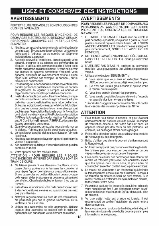
LISEZ ET CONSERVEZ CES INSTRUCTIONSAVERTISSEMENTSPEUT ÊTRE UTILISÉ DANS LES ZONES CUISSON DESCUISINES FAMILIALES.
POUR REDUIRE LES RISQUES D’INCENDIE, DEDECHARGES ELECTRIQUES OU DE DOMMA-GES AUXPERSONNES, OBSERVEZ LES IN-STRUCTIONSSUIVANTES:1. N’utilisez cet appareil que comme cela est indiqué par le
constructeur. Si vous avez des problèmes, contactez lefabriquant à l’adresse ou au numéro de téléphoneindiqués dans la garantie.
2. Avant de pourvoir à l’entretien ou au nettoyage de votreappareil, éteignez-le au tableau des commandes oubloquez le tableau des commandes afin d’éviter de lemettre en marche accidentellement. Si vous ne pouvezpas bloquer le système permettant d’éteindre votreappareil, appliquez un avertissement extérieur d’unefaçon sure, comme par exemple un panneau, sur letableau des commandes.
3. L’assemblage et la connexion électrique doivent être faitspar des personnes qualifiées en respectant les normeset règlements en vigueur, y compris les normes etrèglements concernant les possibilités d’incendie.
4. Il est indispensable qu’il y ait suffisamment d’air pour quela combustion et l’évacuation des gaz à travers le tuyaudu brûleur du combustible ait lieu sans retour de flamme.Suivez les indications données par le fabricant du brûleurainsi que les normes de sécurité comme celles qui sontpubliées par l’Association Nationale pour la Protectioncontre les Incendies National Fire Protection Association(NFPA) et la American Society for Heating, Refrigerationand Air Conditioning Engineers (ASHRAE), et les autoritéslocales en matière de normes.
5. Quand vous coupez ou percez des trous dans le mur oule plafond, n’abîmez pas les fils électriques ou autres.
6. Le ventilateur canalisé doit toujours évacuer l’air versl’extérieur.
7. N’utilisez pas cet appareil avec un appareil contrôlant lavitesse à état solide.
8. Afin de diminuer tout risque d’incendie n’utilisez que desconduits en métal.
9. Votre appareil doit être relié à la terre.ATTENTION - POUR REDUIRE LES RISQUESD’INCENDIE DES MATIERES GRASSES QUI SONT ENTRAIN DE CUIRE:A. Ne laissez jamais ni vos éléments chauffants, ni vos
casseroles ou poêles sur le feu sans les contrôler sivous réglez l’apport de chaleur sur une position élevée.Si vos casseroles ou poêles débordent cela provoquede la vapeur et des éclaboussures de graisse qui peuventprendre feu. Chauffez les huiles lentement à feu bas oumoyen.
B. Faites toujours fonctionner votre hotte quand vous cuisezà des températures élevées ou quand vous cuisinezdes plats flambés.
C. Nettoyez régulièrement les ailes de vos ventilateurs.Ne permettez pas que la graisse s’accumule sur leventilateur ou sur le filtre.
D. Utilisez des casseroles de taille appropriée. Utiliseztoujours des ustensiles de cuisson dont la taille estappropriée à la surface de votre élément de cuisson.
AVERTISSEMENTSPOUR REDUIRE LES RISQUES DE DOMMAGES AUXPERSONNES AU CAS OÙ VOTRE CUISI-NIEREPRENDRAIT FEU, OBSERVEZ LES INSTRUCTIONSSUIVANTES:*1. ETEINDRE LES FLAMMES à l’aide d’un couvercle le
plus hermétique possible, une plaque à gâteaux, ou unplateau en métal, puis éteindre le brûleur. ATTENTIONà NE PAS VOUS BRÛLER. Si les flammes ne s’éteignentpas immédiatement, SORTEZ ET APPELEZ LESPOMPIERS.
2. NE PRENEZ JAMAIS EN MAIN UNE POÊLE OU UNECASSEROLE QUI A PRIS FEU - Vous pourriez vousbrûler.
3. N’UTILISEZ PAS D’EAU, ni torchons ou serviettesmouillés - vous provoqueriez une violente explosion devapeur.
4. Utilisez un extincteur SEULEMENT si:A. Vous savez que vous avez un extincteur Classe
ABC, et vous en connaissez déjà le mode d’emploi.B. Ce n’est pas un très gros incendie et qu’il se limite
à l’endroi où il a explosé.C. Vous êtes en train d’avertir les pompiers.D. Vous avez la possibilité d’essayer d’éteindre l’incendie
en ayant le dos tourné vers une issue.* D’après les “Suggestions concernant la Sécurité contreles incendies des cuisines” publiées par NFPA.
ATTENTION1. Pour réduire tout risque d’incendie et pour évacuer
correctement l’air, assurez-vous de prévoir un conduitde ventilation extérieur. Ne videz pas l’air dans lesespaces limités par des murs ou des plafonds, lescombles, les passages étroits ou les garages.
2. Faites très attention quand vous utilisez des produitsde nettoyage ou des détergents.
3. Évitez d’utiliser des aliments pouvant s’enflammer sousla Range Hood.
4. N’utilisez cet appareil que pour une ventilation générale.Ne l’utilisez pas pour évacuer des matières ou desvapeurs dangereuses ou qui peuvent exploser.
5. Pour éviter de causer des dommages au moteur et derendre les rotors bruyants et/ou non équilibrés, évitezque les sprays pour murs secs, la poussière deconstruction entrent en contact avec la partie électrique.
6. Le moteur de votre hotte a un thermostat qui éteindraautomatiquement le moteur s’il est surchauffé. Le moteurse remettra en marche lorsqu’il se sera refroidi. Si lemoteur continue à s’éteindre et à se remettre en marche,faites vérifier votre hotte.
7. Pour mieux capturer les impuretés de cuisine, le bas devotre hotte devrait être à une distance minimum de 24”et à une distance maximum de 30” au-dessus du plande cuisson.
8. Vu que cette hotte est grande et lourde, il estrecommandé de confier l’installation de cette hotte àdeux personnes.
9. Nous vous recommandons de lire l’étiquette indiquantles caractéristiques de votre hotte pour de plus amplesinformations et exigences.

- 13 -
PREPAREZ LA HOTTEEnlever la hotte dans l’emballage et controller lecontenu.Vous devez recevoir :1 - Hotte1 - Conduit décoratif1 - Sachet avec:
1 - Étrier d’assemblage1 - Collier d’évacuation1 - Étrier de support8 - Vis d’assemblage (4,8 x 38mm Tête ronde)5 - Vis d’assemblage (3,9 x 9,5mm Tête ronde)8 - Chevilles
1 - Instructions pour l’installation
ETRIERD’ASSEMBLAGE
COLLIERD’EVACUATION
ETRIER DE SUPPORT 8 VIS D’ASSEMBLAGE(4,8 x 38mm Tête ronde)
8 CHEVILLES
5 VIS D’ASSEMBLAGE(3,9 x 9,5mm Têteronde)
CONDUITDECORATIVE(modèleRM51000)
CONDUITDECORATIVE(modèleRM52000)

- 14 -
INSTALLATION DU SYSTEMED’EVACUATIONREMARQUE: Pour réduire les risquesd’incendie, n’utilisez que des tuyaux en métal.1. Décidez où le tuyau rond doit être installé,
entre votre hotte et l’extérieur.2. Un tuyau droit et court permettra à votre
hotte de fonctionner d’une façon plus effi-cace.
3. Un tuyau long avec des coudes et destransitions réduira le bon fonctionnementde votre hotte. En utiliser le moins possible.Pour de longues utilisations, il faut untuyau d’évacuation d’air ayant un diamètreplus large.
4. Installez un couvercle sur le toit ou au mur.Reliez un tuyau en métal rond aucouvercle et faites-le aller jusqu’àl’emplacement de votre hotte. Rendez lesjonctions du tuyau hermétiques au moyend’un ruban pour tuyaux.
INSTALLATION ETRIERD’ASSEMBLAGE1. Construisez un cadre en bois pour le
mur dont les vis-pivot ne dépassent pas.Assurez-vous:a) que le cadre est centré au-dessusde l’emplacement de l’installation.b) la hauteur du cadre permettra quel’étrier d’assemblage soit fixé au cadreen respectant les dimensions indiquées.
2. Après avoir terminé la surface du mur,fixez l’étrier d’assemblage au cadre enrespectant les dimensions qui sontindiquées.
CADRE POUR LE MUR
de 38-1/16�(96,7cm) à 44-1/16�
(111,9cm) au-dessus du
plan de cuisson
COUVERCLE DU TOIT
TUYAU ROND
CONDUITDÉCORATIF
HOTTE
COU-VERCLEDU MUR
COUDEROND
DE 24”(61cm) À 30” (76cm)AU-DESSUS
DU PLAN DE CUISSON
(12.9 cm)
38-1/16"(96,7cm) = si la distance entre la hotte etle plan de cuisson c’est de 24”(61cm).44-1/16"(111,9cm) = si la distance entre la hotteet le plan de cuisson c’est de 30” (76cm).
6” (15cm)ADAPTATEUR
INSTALLATIONDE VOTRE HOTTE1.Accrochez votre hotte à l’
étrierè par le trourectangulaire qui setrouve derrière votrehotte. Le trou est plusgrand que l’étrier afin devous permettre d’ajusterle tout horizontalement.Le fond de votre hottedevrait être à entre 24”(61 cm) et 30” (76 cm) au-dessus de la surface decuisson.
2.Fixez votre hotte avec des vis d’assemblage. Utilisez des chevilles pour mur àsec, qui vous sont fournies, si vous ne trouvez pas les vis-pivot ou le cadre.
VISD’ASSEMBLAGE
VISD’ASSEMBLAGE
TROURECTANGULAIRE
PLANCHE DE BOIS POUR L'ADAPTATION
ETRIERED’ASSEMBLAGE

- 15 -
INSTALLATION DE LAPLAQUE
Monter la plaque de l’installation électriqueen la fixant avec 3 vis.
PLAQUE DEL’INSTALLATION
ELECTRIQUE
INSTALLATION ELECTRIQUERemarque: Ce modèle de hotte doit êtrerelié à la terre correctement. Cet articledevrait être installé par un électricienqualifié selon les lois nationales et localesen matière d’électricité.INSTRUCTIONS POUR LA MISE A LATERRECet appareil doit être relié à la terre. En casde court-circuit, la mise à la terre réduit lerisque de décharge électrique enfournissant un câble permettant au courantd’être dévié. Cet appareil est équipé d’uncordon ayant un câble de mise à la terreavec une fiche de mise à la terre. La fichedoit être branchée dans une prise decourant correctement installée et mise à la terre.ATTENTION - Une mise à la terre incorrecte peut entraîner un risque de déchargeélectrique.Consulter un électricien spécialisé si les instructions de mise à la terre ne sontpas tout à fait compréhensibles ou en cas de doute sur le fait de savoir si l’appareilest correctement relié à la terre.Ne pas utiliser de prolongation. Si le cordon d’alimentation est trop court, demanderà un électricien agréé d’installer une prise de courant près de l’appareil.
Régler l’alimentation électrique dans l’espace couvert par le conduit décoratif.Placer la prise femelle à une distance maximum de 33-7/16” (85 cm) de l’endroit oùle plomb sort de la hotte (voir l’illustration ci-contre). S’assurer qu’il n’y ait pasd’interférence avec la zone de fixation du support ou avec le conduit décoratif (àl’endroit où la gaine touche le mur).Mettre la fiche dans la prise femelle.

- 16 -
CONNEXION DU SYSTEMED’EVACUATION
Modèle avec tuyau d’évacuation1. Régler l’étrier de support, de manière à
ce que la largeur soit égale à celle duconduit décoratif supérieur. Installer etfixer les vis d’assemblage pour avoirl’étrier de la largeur exacte.
2. Fixez l’étrier de support au plafond aumoyen des vis d’assemblage et deschevilles comme cela est indiqué.
3. Reliez le collier d’évacuation qui setrouve sur votre hotte au système deconduction qui se trouve au-dessus aumoyen d’un tuyau rond en métal de 6”(15cm).
4. Utilisez un ruban pour tuyauterie afin derendre toutes les jonctions sures etétanches.
5. Introduire le conduit décoratif en leplaçant sur la hotte.
6. Porter le conduit décoratif supérieurjusqu’au plafond et le fixer avec 2 visd’assemblage.
ETRIER DE SUPPORT
VIS D’ASSEMBLAGE
=
=
TUYAU ROND ENMETAL DE 6”
(15cm)
RUBAN POURTUYAUTERIE
CONDUITDÉCORATIF
ATTACHEZ LE CONDUIT AL’ÉTRIER DE SUPPORT AU
MOYEN DES VISD’ASSEMBLAGE
VIS D’ASSEMBLAGE

- 17 -
CONDUITDECORATIFSUPERIEUR
DEFLECTEUR
EVACUATION DEL’AIR (section du haut
du conduit)ETRIER DU
HAUT
MESURETUYAU ROND
EN METAL DE 5”(12,5cm)
Modèle recyclant l’air1. Régler l’étrier de support, de manière à
ce que la largeur soit égale à celle duconduit décoratif supérieur. Installer etfixer les vis d’assemblage pour avoirl’étrier de la largeur exacte.
2. Fixez l’étrier de support au plafond aumoyen des vis d’assemblage et deschevilles comme cela est indiqué.
3. Faites tourner le conduit décoratifsupériuer vers le bas de sorte que laévacuation de l’air soit vers le haut. Faitesglisser le conduit décoratif supériuer dansla section du bas du conduit.
4. Reliez le déflecteur au conduit décoratifsupérieur au moyen de (4) vis à tête plate(qui vous sont fournies).
5. Installer le réducteur sur le collierd’évacuation.
6. Mesurer la distance du haut du réducteurau plafond. Couper une longueur de tuyaurond en métal de 5" (12,5cm) plus petitque cette dimension.
7. Placer le jonction du tuyau au-dessus dudeflecteur. Pour une adaptation parfaite,s’assurer que le jonction du tuyau estorienté vers l’avant.
8. Placer l’ensemble conduit/tuyau sur la hotte avec la partie supérieure inclinéeloin du mur. Tendre le tuyau pour engager le bas du tuyau dans le collierd’évacuation sur la hotte. Incliner le tuyau vers le haut contre le mur. Le jonctiondu tuyau peut être coupé en longueur si nécessaire.
9. Faire arriver le conduit décoratif supérieur jusqu’au plafond et le fixer à l’aide de2 vis d’assemblage.
!
=
=
ETRIER DE SUPPORT
VIS D’ASSEMBLAGE
ATTACHEZ LE CONDUIT AL’ÉTRIER DE SUPPORT AU
MOYEN DES VISD’ASSEMBLAGE
VIS D’ASSEMBLAGE
CONDUITDECORATIFINFERIEUR
JONCTIONDU TUYAU
COLLIERD’EVACUATION
REDUCTEUR
!

- 18 -
ASSEMBLAGE DU FILTRE(MODELE RECYCLANT L’AIR)1. Procurez-vous un filtre à charbon
(B03300488) chez votre fournisseur.2. Installer le filtre en enfilant les 2 languettes
du filtre dans le logement prévu à cet effetet en le faisant tourner vers le haut.
FILTRE A CHARBONENTRETIENUn bon entretien de votre hotte garantiraune excellente performance.
Filtres anti-graisseLes filtres anti-graisse doivent être nettoyésfréquemment. Utilisez une solution contenantun détergent tiède. Les filtres anti-graissepeuvent être lavés au lave-vaisselle. Enlevezles filtres en le poussant vers l’arrière de votrehotte et en les faisant tourner vers le bas.
Filtre à charbonLe filtre à charbon doit être remplacé tous les6 mois. Pour remplacer le filtre pousser leloquet de blocage vers l’intérieur et tournerle filtre vers le bas de manière à retirer les 2languettes de leur logement.
Nettoyage de votre hotteL’acier inoxydable est une des matières lesplus faciles à nettoyer. Un entretien de tempsen temps permettra de le conserver en parfaitétat. Conseils pour le nettoyage:● Eau chaude et savon ou détergent est tout
ce qui est normalement nécessaire.● Après chaque nettoyage, rincez bien à l’eau claire. Essuyez avec un chiffon
propre et doux afin d’éviter les taches d’eau.● Si des décolorations ou des dépôts persistent, utilisez un nettoyant domestique
non abrasif ou de la poudre pour l’acier inoxydable et un peu d’eau et un chiffondoux.
● Dans les cas difficiles, utilisez une éponge en plastique ou une brosse douceavec du nettoyant et de l’eau. Frottez légèrement en suivant la direction dupolissage ou du “grain” de l’acier inoxydable. Evitez de frotter trop fort afin de nepas abîmer la surface.
● NE LAISSEZ PAS les taches trop longtemps.● N’UTILISEZ PAS de laines d’acier ordinaires ou des brosses en acier. Des débris
d’acier pourraient adhérer à la surface et causer de la rouille.● NE PERMETTEZ PAS que des solutions salées, des désinfectants, des
blanchissants ou des produits nettoyants restent en contact avec l’acier pendantlongtemps. Beaucoup de ces produits contiennent des produits chimiques quipourraient causer des dommages. Rincez à l’eau immédiatement s’ils entrent encontact et essuyez avec un chiffon humide.
Les surfaces peintes doivent être nettoyées avec de l’eau tiède additionnée d’undétergent doux seulement.
FILTRES ANTI-GRAISSE
LANGUETTES
LOQUET

- 19 -
FONCTIONNEMENTCommandesLa hotte peut être manœuvrée à l’aide descurseurs situés sous la partie inférieure dela hotte.L’interrupteur de la lumière allume et éteintles lampes.
L’interrupteur du ventilateur permet desélectionner la vitesse de marche dumoteur. Position 0: moteur éteint.Le voyant lumineux s’allume quand leventilateur fonctionne.
INTERRUPTEURDE LA
LUMIÈRE
VOYANTLUMINEUX
INTERRUPTEURDU VENTILATEUR
AMPOULES HALOGENES
Ce modèle de hotte veut deux (2) ampouleshalogènes (Type T4, 12V, 20 W).AVANT DE PROCÉDER À QUELCONQUEOPÉRATION, DÉBRANCHEZ L’APPAREIL.Pour changer les ampoules:1. Dévissez la bague dans le sens contraire
aux aiguilles d’une montre.2. Enlevez l’ampoule en tirant sur le côté
NE LA FAITES PAS TOURNERATTENTION: L’AMPOULE PEUT ETRECHAUDE!
3. Remplacer par une ampoule ayant lesmêmes caractéristiques (T4, 12V, 20 W).Ne touchez pas l’ampoule neuve de vosmains nues!
BAGUE
REMPLACEMENT FUSIBLEDÉBRANCHEZ L’APPAREIL.
Enlevez le conduit décoratif.
Ouvrir le boîtier du fusible.
Remplacez par un fusible du même type(5x20mm, 4A, 125V).
CONDUITDECORATIF
BOÎTERFUSIBLE
FUSIBLE

- 20 -
GARANTIE BROAN-NUTONE LLC LIMITÉE À UN ANBroan-NuTone LLC garantit au consommateur-acheteur de ses produits que ces produits seront sans défauts concernant lesmatières employées et concernant la fabrication pendant une période d’un an à partir de la date d’achat. IL N’Y A AUCUNEAUTRE GARANTIE, EXPLICITE OU IMPLICITE, Y COMPRIS, MAIS NON PAS LIMITEE A, LES GARANTIES IMPLICITESOU CONCERNANT LA CAPACITE COMMERCIALE OU LA CONVENANCE POUR TOUT BUT PARTICULIER. Pendantcette période d’un an, Broan-NuTone LLC réparera ou remplacera, s’il le jugera nécessaire, gratuitement, tout article ou toutepièce qui résulteront défectueux à condition qu’ils aient été utilisée et entretenu correctement.CETTE GARANTIE NE S’ETEND PAS AUX INTERRUPTEURS DES NEON, NEON, LAMPES HALOGENES, AMPOULESd”ILLUMINATION. Cette garantie ne couvre pas (a) l’entretien normal ni (b) tout article ou toute pièce qui aient subi uneutilisation erronée, une négligence, un accident, un entretien erroné ou une réparation (autre que de la part de Broan-NuToneLLC), une installation défectueuse ou bien une installation ne respectant pas les instructions d’installation recommandées. Ladurée de toute garantie implicite est limitée à un an comme cela est spécifié dans la garantie explicite. Quelques états nepermettent pas de limites quant à la durée d’une garantie implicite, par conséquent la limitation indiquée ci-dessus peut ne pasvous concerner.L’OBLIGATION DE REPARER OU DE REMPLACER DE LA PART DE BROAN-NUTONE LLC SERA LE SEUL ET EXCLUSIFREMEDE DE L’ACHETEUR COUVERT PAR CETTE GARANTIE. BROAN-NUTONE LLC NE SERA PAS RESPONSABLEDES DOMMAGES ACCIDENTELS, CONSEQUENTIELS OU SPECIAUX DUS A L’UTILISATION DU PRODUIT OU A SAPERFORMANCE OU EN ETANT LA CONSEQUENCE. Quelques états ne permettent pas l’exclusion ou la limitation desdommages accidentels ou conséquentiels, par conséquent la limitation indiquée ci-dessus peut ne pas vous concerner.Cette garantie vous donne des droits légaux spécifiques, et vous pouvez aussi avoir d’autres droits, qui varient d’Etat à Etat.Cette garantie dépasse toute garantie précédente. Pour avoir droit à la garantie, vous devez (a) avertir la Maison Broan-NuToneLLC à l’adresse indiquée ci-dessous ou téléphoner : 1-800-637-1453, (b) donner le numéro du modèle et l’identification de lapièce défectueuse et (c) décrire la nature de tout défaut de l’article ou de la pièce. Au moment où vous demandez le servicede garantie, vous devez présenter la preuve d’achat avec la date.Broan-NuTone LLC. 926 West State Street, Hartford, WI 53027 (1-800-637-1453)NuTone, Inc., 4820 Red Bank Road, Cincinnati, OH 45227 (1-800-543-8687)Broan-NuTone Canada, Inc. 1140 Tristar Drive, Mississauga, Ontario, L5T 1H9 (1-888-882-7626)
GARANTIE

- 21 -
LEA Y CONSERVE ESTAS INSTRUCCIONESADVERTENCIAINDICADO PARA EL USO EN COCINASDOMÉSTICAS.
PARA EVITAR EL RIESGO DE INCENDIO,CORTOCIRCUITO O DAÑO PARA LASPERSONAS, OBSERVE ATENTAMENTE LASSIGUIENTES NORMAS:1. Use esta unidad solamente de la manera indicada por
el fabricante; si tiene dudas, póngase en contacto conéste a la dirección o teléfono indicados en la garantía.
2. Antes de hacer una revisión o de limpiar la unidad,desconéctela de la red para evitar que se encienda demanera accidental. En el caso de que éste no pueda serdesacti-vado, se indicará en la placa de caracte-risticas.
3. El montaje y la instalación eléctrica debe hacerlos untécnico especializado siguiendo las normas estándar eincluyendo aquellas de construcción anti incendio.
4. Necesita aire suficiente para una apropiada combustióny escape de gases a través del tubo del depósito dequema de combustible. Para evitar que el humo aspiradovuelva a la cocina, siga las directivas del fabricante ylas normas estándar de siguridad así como las normaspublicadas por la Asociación de prevención de incendios(NFPA) y la Socie-dad americana de especialistas encale-facción, refrigeración y aire acondicionado y ademáslas normas de las autoridades locales.
5. Hacer un corte o un taladro en la pared o en el techo nodebe dañar la instalación eléctrica u otras instalacionesocultas en la pared.
6. Los conductos ventiladores deben siempre desalojar alexterior.
7. No use esta unidad con dispositivo de control de lavelocidad a estado sólido.
8. Para evitar el riesgo de incendio, use solamenteconductos de metal.
9. Esta unidad tiene que ser conectada a tierra.
PARA EVITAR EL RIESGO DE FUEGO POR ALTONIVEL DE GRASA:A. Nunca abandone los quemadores con el fuego alto.
La cocción causa humo y restos de grasa que puedenarder. Caliente el aceite a fuego medio o bajo.
B. Encienda siempre la campana cuando cocine a fuegoalto o cuando cocine alimentos fácilmenteinflamables.
C. Limpie con frecuencia los ventiladores. No se debeacumular grasa en el ventilador o en el filtro.
D. Usa el tamañp de cazuela apropiado. Use siempreutensilios de cocina de tamaño y material adecuados.
ADVERTENCIAPARA EVITAR EL RIESGO DE DAÑOS APERSONAS EN CASO DE FUEGO POR ALTONÍVEL DE GRASA, TENGA EN CUENTA LOSIGUIENTE:*1. SOFOQUE LA LLAMA con una tapadera apropiada, una
bandeja metálica ó un utensilio de cocína que puedacubrirla, despues, apague el quemador. ACTÚE CONPRECAUCÍON PARA EVITAR QUEMA-DURAS. Si lallama no se extingue inmedia-tamente, SALGA Y LLAMEA LOS BOMBE-ROS.
2. NUNCA COJA UNA SARTEN EN LLAMAS, porque correel riesgo de quemarse.
3. NO USE AGUA ni paños o toallas húmidas porque puedeprovocarse una violenta humareda.
4. Use un extintor SOLAMENTE si:A. Posee un extintor de clase ABC y sabe
perfectamente cómo usarlo.B. El fuego es pequeño y está controlado en el mismo
sitio en que empezó.C. Ha llamado con anterioridad a los bomberos.D. Puede combatir el fuego retrocedíendo hacia la
salida.* Basado en “Seguridad antifuego en la cocína” publicado
por NFPA.
ADVERTENCIA1. Para reducir el riesgo de incendios y para evacuar
correctamente los humos, asegurarse de haber realizadouna conducción del aire hasta el exterior. No expulsarlos humos en espacios cerrados por paredes o techos,áticos, espacios angostos o garajes.
2. Prestar la máxima atención al utilizar productos delimpieza o detergentes.
3. Evitar el uso de productos alimentarios que puedaninflamarse bajo la campana.
4. Sólo para ventilación total. No use gases de escapepeligrosos o materiales y vapores explosivos.
5. Para evitar daños en el funcionamiento del motor eimpulsores ruidosos y/o desequi-librados, mantengaalejados de la unidad de encendido pulverizadores enseco o polvo.
6. El motor tiene un nivel de sobrecarga térmica que apagaautomáticamente el motor cuando se ha recalentadoexcesivamente. El motor se pone de nuevo enfincionamento cuando la temperatura baja. Si el motorcomienza a encenderse y a apagarse, deberá haceruna revisión de éste.
7. Para limpiar mejor las impurezas al cocinar, la parteinferior de la campana debe estar a una temperaturamínima de 24 grados y máxima de 30 grados por debajode la temperature de la zona de cocción.
8. Debido a su gran tamaño y peso, se recomienda sumontaje por parte de dos técnicos esperializados.
9. Se recomienda leer la placa de caracte-risticas delproducto para ulterior información.

- 22 -
PREPARE LA CAMPANASacar la campana de l’embalaje y controlar el contenido.Recivireis:1 - Campana1 - Tubo decorativo1 - Bolsita con:
1 - Soporte de montaje1 - Casquillo1 - Soporte para el montaje del tubo8 - Tornillos de montaje (4,8 x 38mm cabeza redonda)5 - Tornillos de montaje (3,9 x 9,5mm cabeza redonda)8 - Escarpias
1 - Instrucciones para instalación
SOPORTE DEMONTAJE
CASQUILLO
SOPORTE PARA ELMONTAJE DEL TUBO
8 TORNILLOS DEMONTAJE (4,8 x 38mmcabeza redonda)
8 ESCARPIAS
5 TORNILLOS DEMONTAJE(3,9 x 9,5mm cabezaredonda)
TUBODECORATIVO(modeloRM51000)
TUBODECORATIVO(modeloRM51000)

- 23 -
INSTALACION SOPORTE DEMONTAJE1. Construya una estructura de madera
en la pared que quedará nivelada con laparte interior de los tacos en la pared.Asegúrese de que:a) La estructura se encuentra centrada
por encima de la instalación del tubo.b) La altura de la estructura permite fijar el
soporte de montaje en esta estructurasiguiendo las dimensiones indicadas.
2. Una vez que la superficie de la paredesté acabada, sujete el soporte demontaje siguiendo las dimensionesindicadas.
INSTALACION DEL TUBO DEEXTRACCIONNOTA: para evitar el riesgo de incendio,use solamente material de metal.1. Decida donde va a colocar el tubo de
extracción entre la campana y la parteexterior.
2. Un recorrido de tubo corto y rectopermitirá a la campana funcionar demanera más eficaz.
3. Los recorridos largos de tubo, codos ymanguitos impiden el buenfuncionamiento de la campana. Use elmenor número de ellos posible. Parausos prolongados es necesario un tubode evacuación del aire de mayordiámetro.
4. Instale una cubierta ó una tapa. Una eltubo de metal a la cubierta y retroceda hasta la posición de la campana. Useune cinta para precintar las juntas entre las partes del entubado.
ESTRUCTURA DE MADERA EN LA PARED
38-1/16"(96,7cm) = si la distancia entre lacampana y la zona de cocción es de 24”(61cm).44-1/16"(111,9cm) = si la distancia entre lacampana y la zona de cocción es de 30” (76cm).
UBIERTA DELTEJADO
TUBO
TUBODECORATIVO
CAMPANA
TAPAPARED
MANGUITO
24” (61cm) A 30” (76cm)POR ENCIMA DE LAZONA DE COCCIÓN
De 38-1/16�(96,7cm) a 44-1/
16�(111,9cm) por encima de la zona
de cocción
(12.9 cm)
6” (15cm)ADAPTADOR
INSTALACION DELA CAMPANA1. Cuelgue la campana del
soporte por el agujerorectangulare situadodetrás de la campana. Elagujero es más grandeque el soporte parapermitir el ajuste enhorizontal.La parte inferior de lacampana debe estar auna distancia de 24”(61cm) ó 30” (76cm) porencima de la zona de cocción.
2. Sujete la campana con tornillos de montaje. Use escarpias incluidos en elequipamiento si no dispone de tacos o de la estructura de soporte en madera.
TORNILLOS DEMONTAJE
AGUJERORECTANGULARE
ESTRUCTURA DE MADERA EN LA PARED
SOPORTE DEMONTAJE
TORNILLOS DEMONTAJE

- 24 -
INSTALACION DE LA PLACAMontar la placa del sistema eléctrico fijándolamediante tres tornillos.
PLACA DELSISTEMA
ELÉCTRICO
INSTALACION ELECTRICANota: Este tipo de campana tiene que serconectada a tierra cuidadosamente. Launidad debe instalarla un técnicoelectricista siguiendo las normasnacionales y locales.INSTRUCCIONES DE CONEXIÓN ATIERRAEste aparato se debe conectar a tierra. Encaso de cortocircuito, la conexión a tierrareduce el riego de electrocución ya queposee un hilo de descarga a tierra para lacorriente. Este aparato está equipado conun cable que posee un hilo de toma de tierracon una clavija de tierra. La clavija se debeconectar a un enchufe instaladocorrectamente y conectado a tierra.ADVERTENCIA- una conexión a tierra incorrecta puede provocar riesgos deelectrocución.Consulte a un electricista calificado si no se entienden o si existe alguna dudasobre la correcta conexión a tierra.No utilice un cable de prolongación. Si el cable proporcionado es demasiadocorto, póngase en contacto con un electricista calificado para que instale unenchufe cerca del aparato.
Conecte la alimentación eléctrica en el espacio cubierto por el tubo decorativo.Coloque el enchufe a una distancia máxima de 33-7/16” (85 cm) desde el cable dela campana (véase figura adjunta). Asegúrese de que no interfiera con el área de laabrazadera de sujeción o con el tubo decorativo (donde el tubo decorativo toca conla pared).Conecte la clavija al enchufe.

- 25 -
SOPORTE DEMONTAJE DEL TUBO
ENTUBADO DECANALIZACION
Configuración con tubo1. Regule el soporte de montaje del tubo
de manera que su ancho coincida con eldel tubo decorativo superior. Colocar yfijar los tornillos de montaje para que elsoporte se adapte a dicho ancho.
2. Use tornillos y escarpias para fijar al techoel soporte de montaje del tubo como seindica.
3. Use un tubo de metal de 6” (15cm) dediámetro para unir el casquillo que seencuentra encima de la campana al tubode extracción situado arriba.
4. Use cinta para ajustar todas las junturas yque quede hermético.
5. Introduzca el tubo decorativoconectándolo en la campana.
6. Extienda la parte superior del tubodecorativo hacia el techo y sujétela con2 tornillos de montaje.
FIJE EL TUBO ALSOPORTE CON
TORNILLOS DE MONTAJE
TORNILLOS DEMONTAJE
TUBO DEMETAL DE 6”
(15CM) DE
CINTA
TUBODECORATIVO
TORNILLOS DE MONTAJE
=
=

- 26 -
PARTE SUPERIORDEL TUBO
RESPIRADERODE AIRE
PARTEINFERIORDEL TUBO
CASQUILLO
TUBO DE METALDE 5” (12,5cm) DE
DIÁMETRO
Configuración sin tubo1. Regule el soporte de montaje del tubo
de manera que su ancho coincida con eldel tubo decorativo superior. Colocar yfijar los tornillos de montaje para que elsoporte se adapte a dicho ancho.
2. Use tornillos y escarpias para fijar al techoel soporte de montaje del tubo como seindica.
3. Dé la vuelta a la parte superior del tubode manera que las rejillas de salida delaire estén en la parte superior. Hagadeslizar la parte superior del tubo hastaalcanzar la parte inferior de éste.
4. Una el respiradero de aire con la partesuperior del tubo por medio de cuatrotornillos con cabeza plana (adjuntos).
5. Instale el reductor en el collar de descarga.6. Mida la distancia desde la parte superior
del reductor hasta el techo. Corte a unadistancia de 5" (12,5 cm) alrededor deltubo de metal 5" más corto que su medida.
7. Instale el tubo en el orificio. Para una mejorinstalación, asegurarse de que la junturadel tubo se encuentre en la parte frontal.
8. Instale el tubo en la campana con la partesuperior inclinada con respecto a la pared. Alargar el borde del tubo para sujetarloa la parte inferior del tubo mediante el collar de descarga en la campana. Inclinarla parte superior del tubo decorativo contra la pared. La juntura del tubo sepuede cortar longitudinalmente si es necesario.
9. Extendienda la parte superior deltubo hacia el techo y sujétela con2 tornillos de montaje.
REDUCTOR
REJILLAS DESALIDA DEL AIRE(configuración sin
tubo)SOPORTESUPERIOR
JUNTURADEL TUBO DISTANCIA
!
!
=
=
SOPORTE DEMONTAJE DEL TUBO
FIJE EL TUBO ALSOPORTE CON
TORNILLOS DE MONTAJE
TORNILLOS DEMONTAJE
TORNILLOS DE MONTAJE

- 27 -
INSTALACION DEL FILTRO(CONFIGURACION SIN TUBO)
1. Compre un filtro al carbón (B03300488)a su proveedor habitual.
2. Instalen el filtro introduciendo las doslengüetas del filtro en el alojamiento atal efecto y haciendo que gire haciaarriba.
FILTROS ANTIGRASA
MANTENIMIENTOUn mantenimiento adecuado de la campanaasegura el funcionamiento correcto delaparato.
Filtros antigrasaLos filtros antigrasa deben limpiarse amenudo. Use un detergente que no seafuerte. El filtro antigrasa se puede meter enel lavavajillas. Extraiga el filtro tirando de ellohacia atrás de la campana y girándolos haciaabajo.Filtro al carbónEl filtro debe cambiarse cada seis meses.Para sacar el filtro, empujen el retén haciadentro y giren hacia abajo el filtro hasta quelas dos lengüetas salgan de susalojamientos.Limpieza de la campanaEl acero inoxidable es uno de los meterialesmás fáciles de limpiar, pero seríaaconsejable un especial cuidado en su usopara mantenerla en buen estado. Lacampana se puede limpiar de las siguientesmaneras:● Agua caliente con jabón o detergente es la mejor manera para limpiarla.● Aclárela con agua corriente, séquela con un paño suave y limpio para evitar las
huellas que deja el agua.● Para las manchas o restos de grasa que persistan, use un producto químico
doméstico que no raye ó un limpiador para acero inoxidable con poca agua y unpaño suave.
● Si las manchas persisten, use un estropajo y un cepillo de cerdas suaves con unproducto limpiador y agua. Frote suavemente en el sentido del pulido o de las“vetas” del remate del inoxidable. No apriete demasiado porque podría dañar lasuperficie.
● No deje que las manchas se acumulen durante mucho tiempo.● No use utensilios o cepillos de acero. Pequeñas particulas de acero pueden
adherirse y oxidarse.● No use soluciones salinas, desinfectantes, lejías, o productos de limpieza que
permanezcan en contacto con el acero inoxidable durante largos periodos detiempo. Muchos de estos productos contienen componentes químicos que podríanresultar nocivos. Aclare con agua y seque con un paño limpio.
Las superficies lacadas deben limpiarse solamente con agua tibia y detergente nomuy fuerte.
RETÉN
LENGÜETAS
FILTRO ALCARBÓN
- 28 -
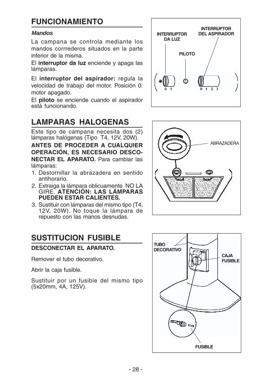
FUNCIONAMIENTOMandosLa campana se controla mediante losmandos corrrederos situados en la parteinferior de la misma.El interruptor da luz enciende y apaga laslámparas.
El interruptor del aspirador: regula lavelocidad de trabajo del motor. Posición 0:motor apagado.El piloto se enciende cuando el aspiradorestá funcionando.
INTERRUPTORDA LUZ
PILOTO
INTERRUPTORDEL ASPIRADOR
LAMPARAS HALOGENASEste tipo de campana necesita dos (2)lámparas halógenas (Tipo T4, 12V, 20W).ANTES DE PROCEDER A CUALQUIEROPERACIÓN, ES NECESARIO DESCO-NECTAR EL APARATO. Para cambiar laslámparas:1. Destornillar la abrazadera en sentido
antihorario.2. Extraiga la lámpara oblicuamente. NO LA
GIRE. ATENCIÓN: LAS LÁMPARASPUEDEN ESTAR CALIENTES.
3. Sustituir con lámparas del mismo tipo (T4,12V, 20W). No toque la lámpara derepuesto con las manos desnudas.
ABRAZADERA
CAJAFUSIBLE
SUSTITUCION FUSIBLEDESCONECTAR EL APARATO.
Remover el tubo decorativo.
Abrir la caja fusible.
Sustituir por un fusible del mismo tipo(5x20mm, 4A, 125V).
TUBODECORATIVO
FUSIBLE

- 29 -
GARANTIA
GARANTIA BROAN-NUTONE LLC POR UN AÑOBroan-NuTone LLC garantiza al consumidor-comprador de sus productos que dichos productos no tendrán defectos en losmateriales o fabricación, durante un periodo de un año a partir de la fecha de la compra. NO HAY OTRO TIPO DEGARANTIAS QUE INCLUYAN O SE LIMITEN EXCLUSIVAMENTE A GARANTIAS IMPLICITAS O DE CAPACIDADCOMERCIAL O CONVE-NIENCIA PARA UN PROPOSITO ESPECIFICO.Durante el periodo de un año, Broan-NuTone LLC, si lo estima conveniente, reparará o reemplazará sin gastos para elusuario cualquier producto o parte de éste que sea defectuosos habiéndose usado correctamente. ESTA GARANTIA NOCUBRE: ESTARTER DE NEON, NEON, LÁMPARAS HALÒGENAS, LÁMPARAS DE ILUMINACIÓN. Tampoco cubre elmantenimiento ni los productos o partes de éstos que hayan sido usados de forma incorrecta, con negligencia, rotosaccidentalmente o por una incorrecta manutención ó reparación (distinta da la realizada por Broan-NuTone LLC), montajeincorrecto ó instalación que no se ajuste a las instrucciones de montaje indicadas. Le duración de la garantía se limita alperiodo de un año como está especificado en la garantía explicita. Algunos paises no permiten un limite en la duración dela garantía implicita; si es asi en su caso, esta limitación arriba indicada podría no aplicarse. LA PRESENTE GARANTIACUBRIRA EXCLUSIVAMENTE AL COMPRADOR LOS SERVICIOS DESCRITOS ANTERIORMENTE. BROAN-NUTONE LLC NO SE HACE RESPONSABLE DE DANOS PRODUCIDOS DE MANERA ACCIDENTAL ORELACIONADOS CON EL USO INCORRECTO DEL PRODUCTO O SU FUNCIONAMIENTO. Algunos paises nopermiten la exclusión o limitación de los daños producidos de manera accidental, si es así en su caso, esta limitación arribaindicada podría no aplicarse. Esta garantía le da derechos legales específicos y podría también disponer de otros derechosque varian de país a país. Esta garantía supera otras garantías dadas con anterioridad. Para disfrutar de la garantía usteddeberá a) Avisar a la dirección abajo indicada ó bien llamar por teléfono al número 1-800-637-1453 b) Dar el número deserie del modelo correspondiente o bien una descripción de la parte averiada, c) Descripción del defecto en el producto obien en una de sus partes. Para requerir un servicio en garantía debe presentar el justificante con la fecha de la compra.Broan-NuTone LLC. 926 West State Street, Hartford, WI 53027 (1-800-637-1453)NuTone, Inc., 4820 Red Bank Road, Cincinnati, OH 45227 (1-800-543-8687)Broan-NuTone Canada, Inc. 1140 Tristar Drive, Mississauga, Ontario, L5T 1H9 (1-888-882-7626)

- 30 -
SERVICE PARTSMODELS RM51000 - RM52000
KEY NO. PART NO. DESCRIPTION
9 B08087294 Grease Filter14 B02300233 Motor Capacitor16 BE3345170 Electrical Box Support19 B03295005 Terminal Box26 B02300891 Halogen Lamp Bulb45 BW0000019 Blower48 B02310187 Motor49 B03295076 Blower Wheel53 B03202007 Rubber Washer60 B02300249 Feeder Cable62 B08091462 Blower Mounting Cover86 B08088378 Discharge collar97 BE3402884 Blower Support (RM51000 model)97 BE3402883 Blower Support (RM52000 model)
107 B03202287 Wires Stop113 B03202433 Nameplate118 BE3345012 Decorative Flue Bottom (RM51000 model)118 BE3344597 Decorative Flue Bottom (RM52000 model)119 BE3343456 Decorative Flue Top (RM51000 model)119 BE3343464 Decorative Flue Top (RM52000 model)120 B08091367 Flue Mounting Bracket145 B032920170 Feeder cable connection Box146 B032920180 Feeder Cable Connection Box Cover147 BR2300132 Junction Clamp151 B032920200 Electrical Box Wires Stop165 B03295008 Control Board Box208 B02300783 Transformer228 B08086252 Controls Board229 B03201014 Warning lamp230 B03295075 Switch Board Box Cover234 B03295072 Control Board Box238 B03295074 Motor Switch Button241 B03295073 Light Switch Button274 B03295035 Fuse Box332 B03295009 Cover407 BE3344985 Blower Support Bracket474 B02300791 Halogen Lamp Housing477 B03295006 Terminal Cover
* B06001991 Blower Assembly (Includes Key Nos. 45, 48,49, 53)
- B03300488 Non-ducted recirculation filter- B08999634 Non-ducted recirculation KIT- B02300782 Fuse- B02300674 Fuse Holder
* Not shown assembled.

- 31 -
LISTE PIECES DE RECHANGEMODELES RM51000 - RM52000
N. PART N. DESCRIPTION
9 B08087294 Filtre anti-graisse14 B02300233 Condensateur16 BE3345170 Support boite installation electrique19 B03295005 Boîte borne26 B02300891 Lampe halogène45 BW0000019 Convoyer48 B02310187 Moteur49 B03295076 Turbine du moteur53 B03202007 Pare chocs60 B02300249 Cable alimentation62 B08091462 Support moteur86 B08088378 Collier d’évacuation97 BE3402884 Support convoyer (mod.RM51000)97 BE3402883 Support convoyer (mod.RM52000)
107 B03202287 Serre cable113 B03202433 Plaquette logo118 BE3345012 Conduit décoratif inférieur (mod.RM51000)118 BE3344597 Conduit décoratif inférieur (mod.RM52000)119 BE3343456 Conduit décoratif supérieur (mod.RM51000)119 BE3343464 Conduit décoratif supérieur (mod.RM52000)120 B08091367 Etrier d’assemblage145 B032920170 Boite cable alimentation146 B032920180 Couvercle boite cable alimentation147 BR2300132 Borne151 B032920200 Serre cable165 B03295008 Boîte installation electrique208 B02300783 Trasformateur228 B08086252 Circuite commandes229 B03201014 Lampe temoin230 B03295075 Couvercle commandes234 B03295072 Boite commandes238 B03295074 Bouton moteur241 B03295073 Bouton lumière274 B03295035 Boîter fusible332 B03295009 Bouchon407 BE3344985 Etrier support convoyer474 B02300791 Boîte lampe halogène477 B03295006 Couvercle borne
* B06001991 Ensemble moteur (Comprenant n. 45, 48,49, 53)
- B03300488 Filtre version recyclant l’air- B08999634 Kit version recyclant l’air- B02300782 Fusible- B02300674 Porte-fusible
* Illustrées separement.

- 32 -
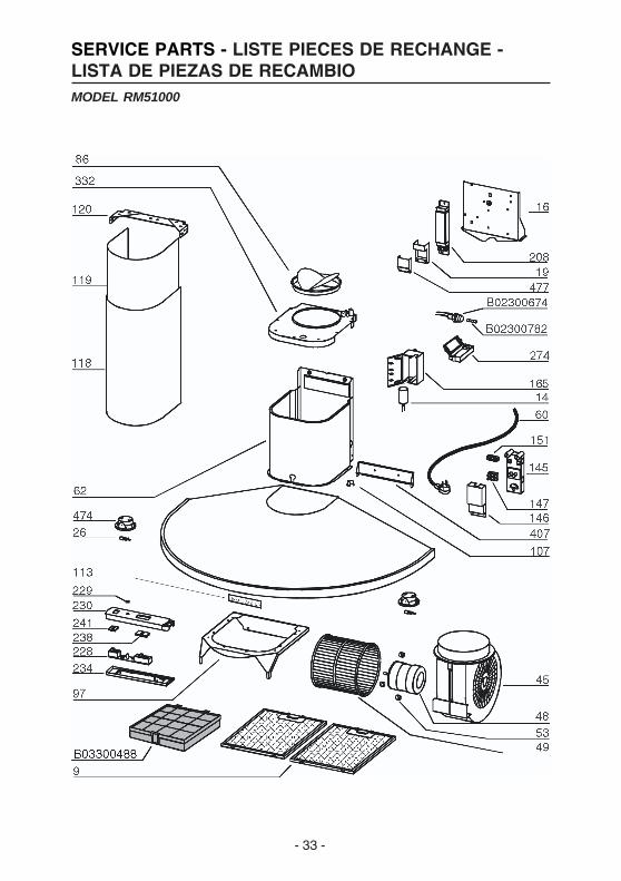
LISTA DE PIEZAS DE RECAMBIOMODELOS RM51000 - RM52000
CÓD. N. PIEZA N. DESCRIPCIÓN
9 B08087294 Filtro antigrasa14 B02300233 Condensador16 BE3345170 Soporte de la caja de instalación eléctrica19 B03295005 Caja del cuadro eléctrico26 B02300891 Lámpara halógena45 BW0000019 Convoyador48 B02310187 Motor49 B03295076 Manilla del motor53 B03202007 Almohadilla antivibraziones60 B02300249 Cabos62 B08091462 Soporte motor86 B08088378 Casquillo97 BE3402884 Soporte convoyador (modelo RM51000)97 BE3402883 Soporte convoyador (modelo RM52000)
107 B03202287 Sujeta cabos113 B03202433 Placa marca118 BE3345012 Tubo decorativo inferior (modelo RM51000)118 BE3344597 Tubo decorativo inferior (modelo RM52000)119 BE3343456 Tubo decorativo superior (modelo RM51000)119 BE3343464 Tubo decorativo superior (modelo RM52000)120 B08091367 Soporte de montaje del tubo145 B032920170 Caja cabos alimentación146 B032920180 Tapa de la caja cabos alimentación147 BR2300132 Terminal151 B032920200 Sujeta cabos165 B03295008 Caja de instalación eléctrica208 B02300783 Trasformador228 B08086252 Base de los mandos229 B03201014 Piloto230 B03295075 Tapa de la caja mandos234 B03295072 Caja de los mandos238 B03295074 Mando motor241 B03295073 Mando iluminación274 B03295035 Caja fusible332 B03295009 Tapa407 BE3344985 Soporte convoyador474 B02300791 Caja de la lámpara halógena477 B03295006 Tapa del cuadro eléctrico
* B06001991 Conjunto motor (Incluye los N. 45, 48,49, 53)
- B03300488 Filtro configuración sin tubo- B08999634 Equipo configuración sin tubo- B02300782 Fusible- B02300674 Portafusible
* Se encuentran por separado.
- 33 -
SERVICE PARTS - LISTE PIECES DE RECHANGE -LISTA DE PIEZAS DE RECAMBIOMODEL RM51000

- 34 -
SERVICE PARTS - LISTE PIECES DE RECHANGE -LISTA DE PIEZAS DE RECAMBIOMODEL RM52000


- 36 -04306824/1