Embed Size (px)
Citation preview
BROAN PIV1250SERIES
POWLE
,i_ INTENDED FOR DOMESTIC COOKING ONLY ,i_
,_, _ WARNING
TO REDUCE THE RISK OF FIRE, ELECTRIC SHOCK, OR INJURYTO PERSONS, OBSERVE THE FOLLOWING:1. Use this unit only in the manner intended by the manufacturer. If you
have questions, contact the manufacturer at the address or tele-phone number listed in the warranty.
2. Before servicing or cleaning unit, switch power off at service paneland lock service panel to prevent power from being switched onaccidentally. When the service disconnecting means cannot belocked, securely fasten a prominent warning device, such as a tag,to the service panel.
3. installation work and electrical wiring must be done by a qualifiedperson(s) in accordance with all applicable codes and standards,including fire-rated construction codes and standards.
4. Sufficient air is needed for proper combustion and exhausting ofgases through the flue (chimney) of fuel burning equipment to pre-vent backdrafting. Follow the heating equipment manufacturer'sguidelines and safety standards such as those published by the Na-tional Fire Protection Association (NFPA), and the American Soci-ety for Heating, Refrigeration and Air Conditioning Engineers(ASHRAE), and the local code authorities.
5. When cutting or drilling into wall or ceiling, do not damage electricalwiring and other hidden utilities.
6. Ducted fans must always be vented to the outdoors.7. Do not use this unit with any separate solid-state speed control device.8. To reduce the risk of fire, use only metal ductwork.9. This unit must be grounded.
TO REDUCE THE RISK OF A RANGE TOP GREASE FIRE:
A. Never leave surface units unattended at high settings. Boilovers causesmoking and greasy spillovers that may ignite. Heat oils slowly onlow or medium settings.
B. Always turn hood ON when cooking at high heat or when flambeingfood (i.e. Crepes Suzette, Cherries Jubilee, Peppercorn BeefFlambe').
C. Clean ventilating fans frequently. Grease should not be allowed toaccumulate on fan or filter.
D. Use proper pan size. Always use cookware appropriate for the sizeof the surface element.
,_ ,_, WARNING
TO REDUCE THE RISK OF INJURY TO PERSONS IN THE EVENTOF A RANGE TOP GREASE FIRE, OBSERVE THE FOLLOWING:*1. SMOTHER FLAMES with a close-fitting lid, cookie sheet, or metal
tray, then turn off the burner. BE CAREFUL TO PREVENT BURNS.If the flames do not go out immediately, EVACUATE AND CALLTHE FIRE DEPARTMENT.
2. NEVER PICK UP A FLAMING PAN - You may be burned.3. DO NOT USE WATER, including wet dishcloths or towels - violent
steam explosion will result.4. Use an extinguisher ONLY if:
A. You know you have a Class ABC extinguisher and you alreadyknow how to operate it.
B. The fire is small and contained in the area where it started.
C. The fire department is being called.D. You can fight the fire with your back to an exit.* Based on "Kitchen Fire Safety Tips" published by NFPA.
,_, CAUTION1. To reduce risk of fire and to properly exhaust air, be sure to duct air
outside. Do not vent exhaust air into spaces within walls or ceilingsor into attics, crawl spaces, or garages.
2. Take care when using cleaning agents or detergents.3. Avoid using food products that produce flames under the Range
Hood.
4. For general ventilating use only. Do not use to exhaust hazardousor explosive materials and vapors.
5. To avoid motor bearing damage and noisy and/or unbalancedimpellers, keep drywall spray, construction dust, etc. off power unit.
6. Your hood motor has a thermal overload which will automaticallyshut off the motor if it becomes overheated. The motor will restartwhen it cools down. If the motor continues to shut off and restart,have the hood serviced.
7. For best capture of cooking impurities, the bottom of the hood shouldbe a minimum of 24" and a maximum of 30" above the cookingsurface.
8. Two installers are recommended.
9. Use with approved cord-connection kit only.10. Please read specification label on product for further information
and requirements.
INSTALL THE DUCTWORK CONNECT DUCTWORK
NOTE: To reduce the risk of fire, use only metal ductwork.
1. Decide where the ductwork will run between the hood and theoutside.
2. A straight, short duct run will allow the hood to perform mostefficiently.
3. Long duct runs, elbows, and transitions will reduce the performanceof the hood. Use as few of them as possible. Larger ducting maybe required for best performance with longer duct runs.
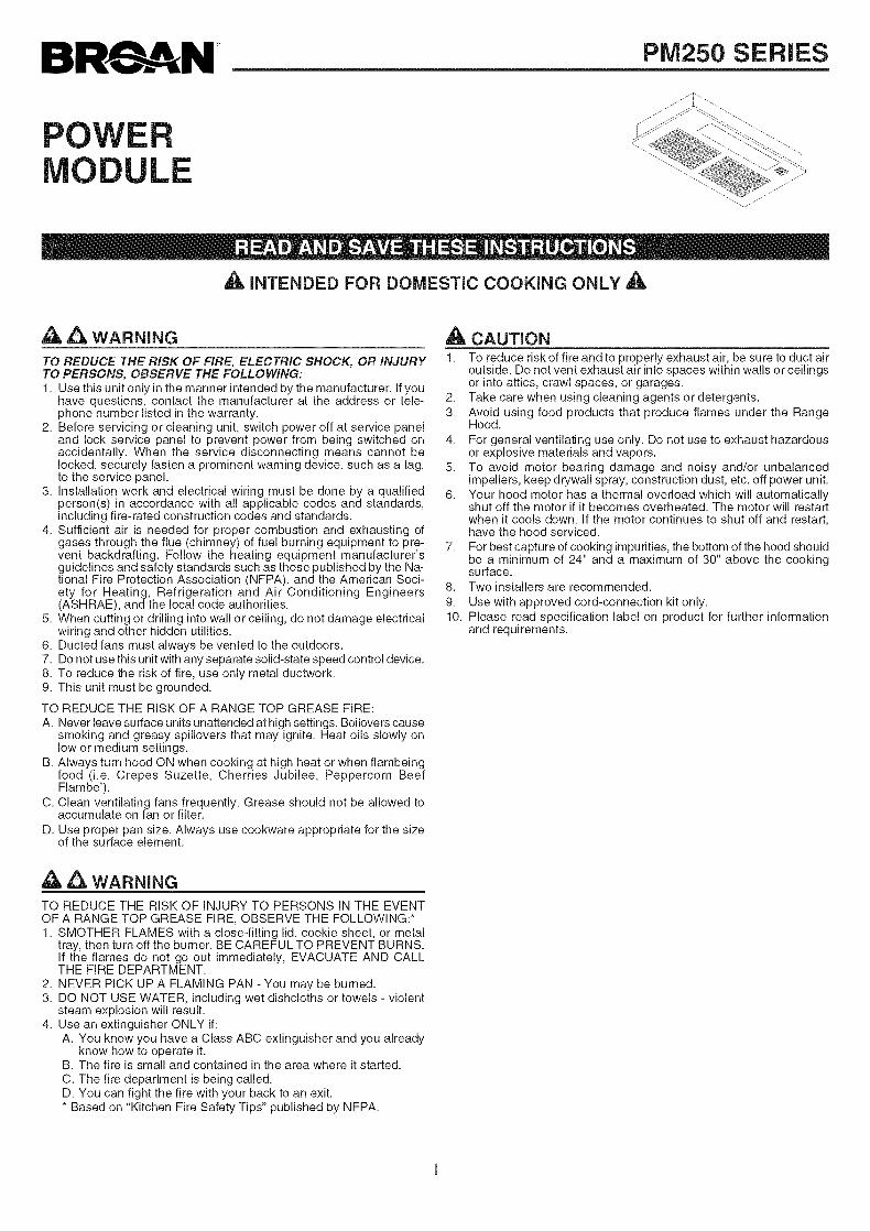
4. Install a roof or wall cap. Connect round metal ductwork to capand work back towards hood location. Use duct tape to seal thejoints between ductwork sections.
ROOFCAP\
Ducted Configuration1. Use 7" round metal duct to connect the discharge collar on the
hood to the ductwork above. An optional 7" round damper maybe used (purchased seperately).
2. Use duct tape to make all joints secure and air tight.
Non-Ducted Recirculation Configuration1. Connect a 7" round metal duct to the discharge opening so
that the air is sent outside the cabinet and sent back into theroom.
2. Use duct tape to make all joints secure and air tight.
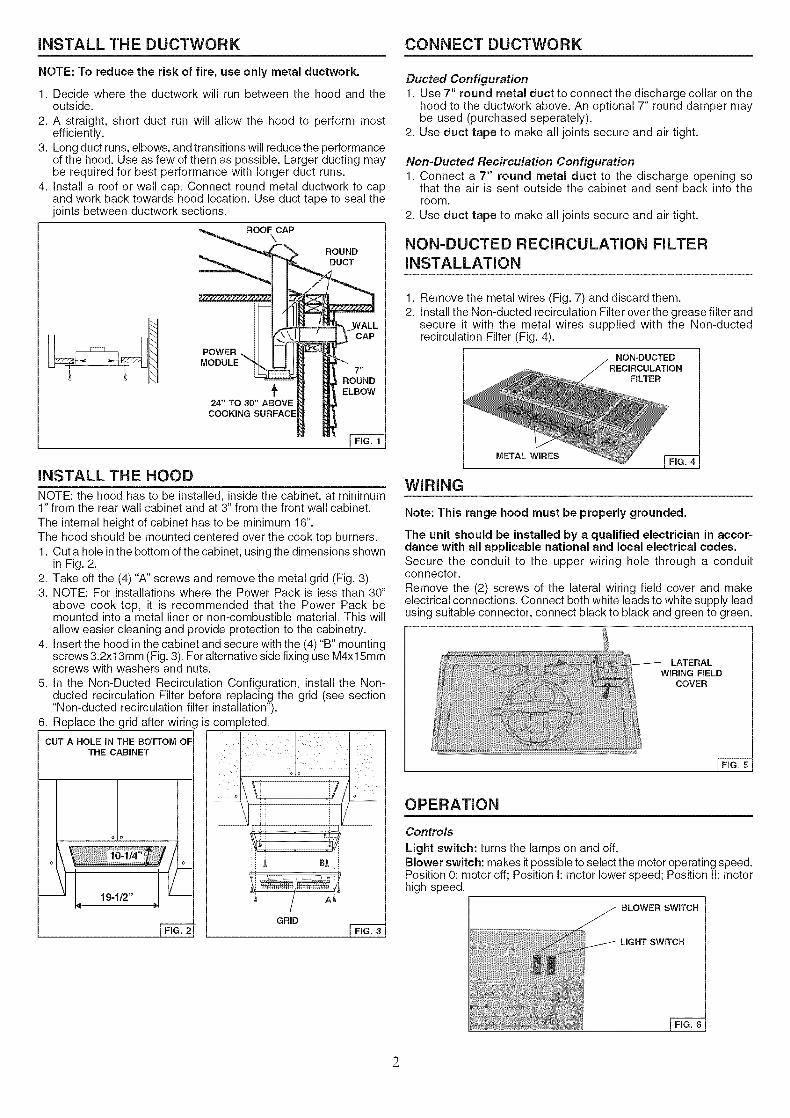
NON-DUCTED REClRCULATION FILTERINSTALLATION
POWER
1. Remove the metal wires (Fig. 7) and discard them.2. Install the Non-ducted recirculation Filter over the grease filter and
secure it with the metal wires supplied with the Non-ductedrecirculation Filter (Fig. 4).
NON-DUCTED
RLTER
INSTALL THE HOOD
NOTE: the hood has to be installed, inside the cabinet, at minimum1" from the rear wall cabinet and at 3" from the front wall cabinet.
The internal height of cabinet has to be minimum 16".The hood should be mounted centered over the cook top burners.1. Cut a hole inthe bottom of the cabinet, using the dimensions shown
in Fig. 2.2. Take off the (4) "A" screws and remove the metal grid (Fig. 3).3. NOTE: For installations where the Power Pack is less than 30"
above cook top, it is recommended that the Power Pack bemounted into a metal liner or non-combustible material. This willallow easier cleaning and provide protection to the cabinetry.
4. Insert the hood in the cabinet and secure with the (4)"B" mountingscrews 3.2x13mm (Fig. 3). For alternative side fixing use M4xl 5mmscrews with washers and nuts.
5. In the Non-Ducted Recirculation Configuration, install the Non-ducted recirculation Filter before replacing the grid (see section"Non-ducted recirculation filter installation").
6. Replace the grid after wiring is completed.
CUT A HOLE IN THE BOTTOM OFTHE CABINET
o o
19-1/2"
I FIG. 2
GRID
WIRING
METAL WIRES
Note: This range hood must be properly grounded.
The unit should be installed by a qualified electrician in accor=dance with all applicable national and local electrical codes.Secure the conduit to the upper wiring hole through a conduitconnector.
Remove the (2) screws of the lateral wiring field cover and makeelectrical connections. Connect both white leads to white supply leadusing suitable connector, connect black to black and green to green.
LATERALWIRING FIELD
COVER
OPERATION
Controls
Light switch: turns the lamps on and off.Blower switch: makes it possible to select the motor operating speed.Position O: motor off; Position I: motor lower speed; Position II: motorhigh speed.
SLOWER SWITCH
LIGHT SWITCH
2
MAINTENANCEALWAYS SWITCH OFF THE ELECTRiCiTY SUPPLY BEFORECARRYING OUT ANY OPERATIONS ON THE APPLIANCE.
Grease Filter
The grease filter should be cleaned frequently. Use a warm detergentsolution. Grease filter is dishwasher safe.
To remove the grease filter: remove the (4) screws and take off themetal grid. Take off the metal wires and remove the grease filter.
METAL WIRES
FILTER _
Non-Dueted Recirculation Filter
The Non-Ducted Recirculation filter should be changed every 6months.To remove the Non-Ducted Recirculation filter:
1. Remove the grid taking off the (4) "A" screws 3.gx6mm (Fig. 3).2. Remove the metal wires (Fig. 4) and replace the Non-ducted
recirculation Filter.
Cleaning
Occasional care will help preserve its fine appearance.• Clean with warm water and mild detergent only.• Follow all cleaning by rinsing with clear water.• Wipe dry with clean, soft cloth.
Light bulbs
This range hood requires two 40-Watt light bulbs (not included).To change bulbs:1. Remove the 2.gx9.5mm screw securing the light fitting.2. Pull down lens to remove.3. Replace with light bulbs of the same type (MAX 40W, 120V,
Candelabra Base Bulb). CAUTION: BULB MAY BE HOT!
SERVICE PARTS
KEY NO. PART NO.5 B031181525 B031276819 B0808792223 B0329509524 B0329509427 B0201127028 B0230028029 B03294794230 BE3348475236 B02300822236 B02300826237 B02300823237 B02300827332 BE3248476415 B03202454CAS R730090
B06108604
B08999040
DESCRIPTIONGrid (White)Grid (Silver)Grease FilterUpper LampholderLower LampholderMetal WireLampholderLight FittingControls ClosingBlower Switch (White)Blower Switch (Black)Light Switch (White)Light Switch (Black)Cover ControlsStrain Relief BushingBlower AssemblySocket Assembly(Includes key No.24, 23, 28)"40 Watt Max.CandelabraBulbs not included"Non-Ducted Filter Kit(purchased separately)
CAS
28
27
24
.... 23
9
5
29
WARRANTY
BROAN=NUTONE LLC ONE YEAR LIMITED WARRANTY
Broan-NuTone LLC warrants to the original consumer purchaser of its products that such products will be free from defects inmaterials or workmanship for a period of one year from the date of original purchase. THERE ARE NO OTHER WARRANTIES,EXPRESS OR IMPLIED, INCLUDING, BUT NOT LIMITED TO, IMPLIED WARRANTIES OR MERCHANT ABILITY OR FITNESSFOR A PARTICULAR PURPOSE.
During this one-year period, Broan-NuTone LLC will, at its option, repair or replace, without charge, any product or part which isfound to be defective under normal use and service.
THIS WARRANTY DOES NOT EXTEND TO FLUORESCENT LAMP STARTERS, TUBES, HALOGEN AND INCANDESCENDTBULBS. This warranty does not cover (a) normal maintenance and service or (b) any products or parts which have been subjectto misuse, negligence, accident, improper maintenance or repair (other than by Broan-NuTone LLC), faulty installation or installationcontrary to recommended installation instructions.
The duration of any implied warranty is limited to the one-year period as specified for the express warranty. Some states do notallow limitation on how long an implied warranty lasts, so the above limitation may not apply to you.BROAN-NUTONE LLC'S OBLIGATION TO REPAIR OR REPLACE, AT BROAN-NUTONE LLC'S OPTION, SHALL BE THEPURCHASER'S SOLE AND EXCLUSIVE REMEDY UNDER THIS WARRANTY. BROAN-NUTONE LLC SHALL NOT BE LIABLEFOR INCIDENTAL, CONSEQUENTIAL OR SPECIAL DAMAGES ARISING OUT OF OR IN CONNECTION WITH PRODUCT USE
OR PERFORMANCE. Some states do not allow the exclusion or limitation of incidental or consequential damages, so the abovelimitation or exclusion may not apply to you.
This warranty gives you specific legal rights, and you may also have other rights, which vary from state to state. This warrantysupersedes all prior warranties.To qualify for warranty service, you must (a) notify Broan-NuTone LLC at the address stated below or telephone: 1-800-637-1453,(b) give the model number and part identification and (c) describe the nature of any defect in the product or part. At the time ofrequesting warranty service, you must present evidence of the original purchase date.Broan-NuTone LLC. 926 West State Street, Hartford, WI 53027 (1-800-637-1453)NuTone, Inc., 4820 Red Bank Road, Cincinnati, OH 45227 (1-800-543-8687)Broan=NuTone Canada, Inc. 1140 Tristar Drive, Mississauga, Ontario, L5T 1H9 (1-888-882-7626)
BROAN S#RIF PIVI250
LEENCASTRA
HOTTELE
_b, POUR UTIMSATION DOIVlESTIQUE SEULEIVIENT ,_,
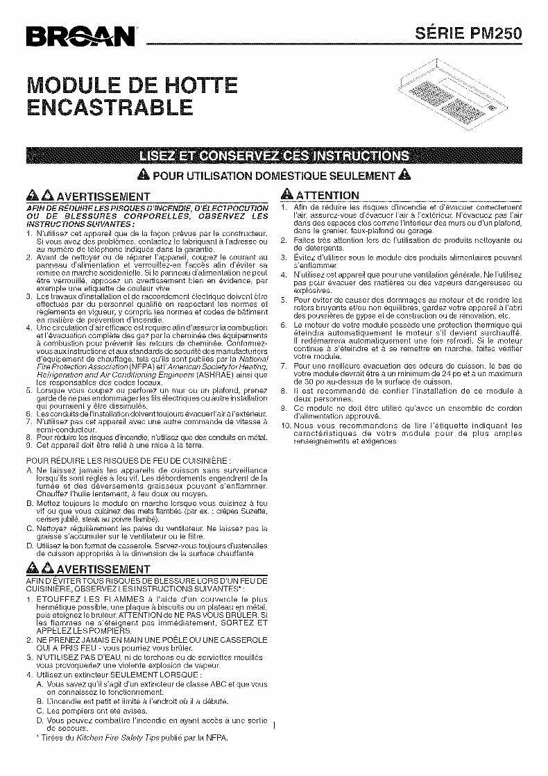
,_ _, AVERTISSEIVlENTAFIN DE R_-DUIRE LES RISQUES D'INCENDIE, D'E-LECTROCUTIONOU DE BLESSURES CORPORELLES, OBSERVEZ LESINSTRUCTIONS SUIVANTES :
1. N'utilisez cet appareil que de la fagon prevue par le constructeur.Si vous avez des problemes, contactez le fabriquant b. I'adresse ouau num6ro de tel6phone indiqu6s dans la garantie.
2. Avant de nettoyer ou de reparer I'appareil, coupez le courant aupanneau d'alimentation et verrouillez-en I'acc_s afin d'6viter saremise en marche accidentelle. Si le panneau d'alimentation ne peut6tre verrouill6, apposez un avertissement bien en evidence, parexemple une etiquette de couleur vive.
3. Les travaux d'installation et de raccordement 61ectrique doivent 6treeffectues par du personnel qualifi6 en respectant les normes etreglements en vigueur, y compris les normes et codes de b&timenten mati_re de pr6vention d'incendie.
4. Une circulation d'air efficace est requise afin d'assurer la combustionet 1'6vacuation complete des gaz par la chemin6e des 6quipementsb. combustion pour pr6venir les retours de chemin6e. Conformez-vous aux instructions et aux standards de s6curit6 des manufactu tiersd'6quipement de chauffage, tels qu'ils sont publi6s par la NationalFire Protection Association (NFPA) et I'American Society for Heating,Refrigeration and Air Conditioning Engineers (ASHRAE) ainsi queles responsables des codes Iocaux.
5. Lorsque vous coupez ou perforez un mur ou un plafond, prenezgarde de ne pas endommager les ills electriques ou autre installationqui pourraient y 6tre dissimules.
6. Les conduits de I'installation doivent toujou rs 6vacuer I'air b.l'ext6rieu r.7. N'utilisez pas cet appareil avec une autre commande de vitesse b.
semi-conducteur.8. Pour r6duire les risques d'incendie, n'utilisez que des conduits en m6tal.9. Cet appareil doit 6tre reli6 b. une mise b. la terre.
,_ ATTENTION1. Afin de r6duire les risques d'incendie et d'evacuer correctement
I'air, assurez-vous d'6vacuer Fair & I'ext6rieur. N'evacuez pas Fairdans des espaces clos comme I'int6rieur des murs ou d'un plafond,dans le grenier, faux-plafond ou garage.
2. Faites tres attention lots de I'utilisation de produits nettoyants oude detergents.
3. €:vitez d'utiliser sous le module des produits alimentaires pouvants'enflammer.
4. N'utilisez cet appareil que pour une ventilation gen6rale. Ne I'utilisezpas pour evacuer des mati_res ou des vapeurs dangereuses ouexplosives.
5. Pour 6viter de causer des dommages au moteur et de rendre lesrotors bruyants et/ou non 6quilibr6s, gardez votre appareil b. I'abrides poussi@es de gypse et de construction ou de renovation, etc.
6. Le moteur de votre module poss_de une protection thermique qui6teindra automatiquement le moteur s'il devient surchauffe.II redemarrera automatiquement une fois refroidk Si le moteurcontinue & s'6teindre et b. se remettre en marche, faites v6rifiervotre module.
7. Pour une meilleure 6vacuation des odeurs de cuisson, le bas devotre module devrait 6tre & un minimum de 24 poet b. un maximumde 30 po au-dessus de la surface de cuisson.
8. II est recommande de confier I'installation de ce module b.deux personnes.
9. Ce module ne doit 6tre utilis6 qu'avec un ensemble de cordond'alimentation approuve.
10. Nous vous recommandons de life I'etiquette indiquant lescaract6ristiques de votre module pour de plus amplesrenseignements et exigences.
POUR RFt:DUIRE LES RJSQUES DE FEU DE CUJSJNJERE :
A. Ne laissez jamais les appareils de cuisson sans surveillanceIorsqu'ils sont r6gles & feu vif. Les debordements engendrent de lafumee et des deversements graisseux pouvant s'enfiammer.Chauffez I'huile lentement, _. feu doux ou moyen.
B. Mettez toujours le module en marche Iorsque vous cuisinez b, feuvif ou que vous cuisinez des mets flambes (par ex. : cr6pes Suzette,cerises jubile, steak au poivre flambe).
C. Nettoyez r6guli_rement les pales du ventilateur. Ne laissez pas lagraisse s'accumuler sur le ventilateur ou le filtre.
D. Utilisez le bon format de casserole. Servez-vous toujours d'ustensilesde cuisson appropri6s b. la dimension de la surface chauffante.
,_,,_ AVERTISSEIVIENTAFIN D'C:VITER TOUS RISQUES DE BLESSURE LORS D'UN FEU DECUISINIERE, OBSERVEZ LES INSTRUCTIONS SUIVANTES* :
1. €:TOUFFEZ LES FLAMMES a I'aide d'un couvercle le plushermetique possible, une plaque a biscuits ou un plateau en m6tal,puis 6teignez le brQleur. ATTENTION de NE PAS VOUS BRULER. Siles fiammes ne s'6teignent pas imm6diatement, SORTEZ ETAPPELEZ LES POMPIERS.
2. NE PRENEZ JAMAIS EN MAIN UNE POE_LE OU UNE CASSEROLEQUI A PRIS FEU - vous pourriez vous brQler.
3. N'UTILISEZ PAS D'EAU, ni de torchons ou de serviettes mouill6s -vous provoqueriez une violente explosion de vapeur.
4. Utilisez un extincteur SEULEMENT LORSQUE :
A. Vous savez qu'il s'agit d'un extincteur de classe ABC et que vousen connaissez le fonctionnement.
B. L'incendie est petit et limite & I'endroit o_ il a d6bute.
C. Les pompiers ont et6 avises.D. Vous pouvez combattre I'incendie en ayant acc_s b. une sortie
de secours.
* Tir6es du Kitchen Fire Safety Tips publi6 par la NFPA.
iNSTALLATiON DU SYSTEME DE CONDUITS
NOTE : Pour r6duire les risques d'incendie, n'utilisez que desconduits en m6tal.
1. D6terminer par o_passera leconduit, entre votre module et I'ext6rieur.2. Un conduit droitetcourt permettra _.votre moduledefonctionnerplus
efficacement.3. Un conduit long avec des coudes et des transitions r6duira la
performance de votre module. En utiliser le moins possible. Pourune grande distance, ilfaut unconduit d'6vacuation d'air au diam_treplus grand.
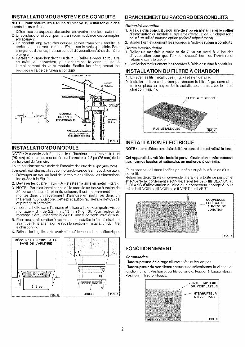
4. Installer un capuchon detoit ou de mur. Relier leconduit circulaireen m6tal au capuchon, puis acheminer le conduit jusqu'&I'emplacement de votre module. Sceller herm6tiquement lesraccords & I'aide de ruban _.conduits.
MODULEDE HOTFE
ENCASTRABLE
DE 24 po (61cm) ._ 30 po
{76 cm) AU-DESSUS
1
INSTALLATION DU MODULE
NOTE :le module doit 6tre install6 & rint6rieur de I'armoire & 1 po(25 mm) minimum du mur arri_re de I'armoire et & 3 po (76 mm) de lapartie avant de I'armoire.La hauteur interne minimale de I'armoire doit 6tre de 16 po (406 mm).Lemodule doit6tre install6 au centre, au-dessus de la surface de cuisson.1. D6couper un trou au fond de I'armoire en utilisant les dimensions
indiqu6es & la Fig. 2.2. D6visser les quatre (4) vis <<A >>et retirer la grille en m6tal (Fig. 3).3. NOTE : Pour les installations oQ le module se trouve & moins de
30 po au-dessus du plan de cuisson, il est recommand6 de lemonter dans un rev6tement d'armoire en m6tal ou dans unmat6riau incombustible. Cette pr6caution facilitera le nettoyageet prot6gera I'armoire.
4. Ins6rer la hotte dans I'armoire et la fixer & I'aide des quatre vis demontage <<B >>de 3,2 mm x 13 mm (Fig. 3). Pour I'option demontage lat6ral, utiliser les vis M4 x 15 mm avec rondelles et 6crous.
5. Pour une configuration & recirculation, installer le filtre & charbonavant de r6installer la grille (voir la section <<Installation du filtre&charbon >>).
6. R6installer la grille apr_s avoir effectu6 le raccordement 61ectrique.
DECOUPER UN TROU ,&, LA
BASE DE L'ARMONRE
o o
19 ½ po
[ FiG. 2 GRILLE
BRANCHEMENT DU RACCORD DES CONDUITS
Hottes b #vacuation
1. ,_ I'aide d'un conduit circulaire de 7 po en m6taJ, relier le colJierd'6vacuation du module au syst_me d'6vacuation. Un clapet rondpeut 6tre utilis6 comme option (achet6 s6par6ment).
2. Sceller herm6tiquement les raccords &raide de ruban a conduits.
Hottes _ recirculation1. Relier un conduit circulaire de 7 po en m6tal & la bouche
d'6vacuation pour que I'air soit 6vacu6 hors de I'armoire etretourn6 dans la piece.
2. Sceller herm6tiquement les raccords &raide de ruban a conduits.
iNSTALLATiON DU FILTRE .&.CHARBON
1. Enlever les ills m6talliques (Fig. 7) et s'en d6faire.2. Installer le filtre & charbon par-dessus le filtre & graisses et le
tenir en place au moyen de ills m6talliques fournis avec le filtre &charbon (Fig. 4).
FILTRE ,& CHARBON
FILS METALLIQUES
INSTALLATION ELECTRIQUE
NOTE :ce module de module doit 6tre correctement reli6 a la terre.
Cet appareil devrait 6tre install6 par un 61ectricien conform6mentaux normes locales et nationales en mati_re d'61ectricit&
Faire passer le fil dans I'orifice pour cable sup6rieur & I'aide d'unserre-fil.Retirer les deux (2) vis du couvercle lat6ral de la bofte de jonction eteffectuer le raccordement 61ectrique. Relier les deux fils BLANCS aufil BLANC d'alimentation & I'aide d'un connecteur appropri6, puisrelier le fil NOIR au fil NOIR et le fil VERT au fil VERT.
COUVERCLELATERAL DELA BO'iTE DE
JONCTmON
FONCTIONNEMENT
Commandes
Finterrupteur d'6clairage allume et 6teint les lampes.
L:interrupteur du ventilateur permet de s61ectionner la vitesse defonctionnement. Position 0 :ventilateur arr6t6; Position I : basse vitesse;Position II : haute vitesse.
INTERRUPTEUR
VENTNLATEUR
2
ENTRETIEN
COUPERTOUJOURS L'ALIMENTATIONELECTRIQUE AVANTD'EFFECTUER UNE QUELCONQUE OPERATION SUR L'APPAREIL.
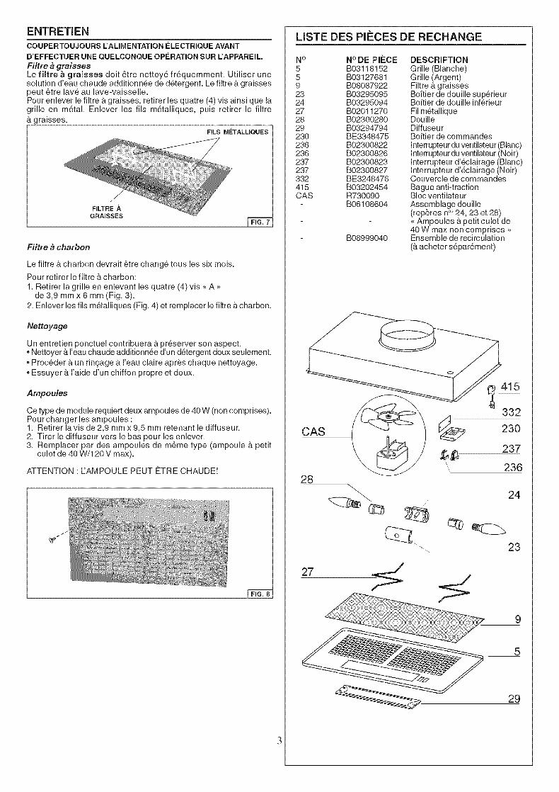
Filtre _ graissesLe fiJtre a graisses doit 6tre nettoy6 fr6quemment. Utiliser unesolution d'eau chaude additionn6e de d6tergent. Le filtre & graissespeut 6tre lav6 au lave-vaisselle.Pour enlever le filtre & graisses, retirer les quatre (4) vis ainsi que lagrille en m6tal. Enlever les fils m6talliques, puis retirer le filtre& graisses.
FILSMETALUQUES
FILTRE A
Filtre b charbon
Le filtre & charbon devrait 6tre chang6 tous les six mois.
Pour retirer le filtre & charbon:1. Retirer la grille en enlevant les quatre (4) vis <<A _>
de 3,9 mm x 6 mm (Fig. 3).2. Enlever les fils m6talliques (Fig. 4) et remplacer le filtre &charbon.
Nettoyage
Un entretien ponctuel contribuera & pr6server son aspect.• Nettoyer & I'eau chaude additionn6e d'un d6tergent doux seulement.
Proc6der & un rin£age & I'eau claire apr_s chaque nettoyage.Essuyer & I'aide d'un chiffon propre et doux.
Ampoules
Ce type de module requiert deux ampoules de 40 W (non comprises).Pour changer les ampoules :1. Retirer lavis de 2,9 mm x 9,5 mm retenant le diffuseur.2. Tirer le diffuseur vers le bas pour les enlever.3. Remplacer par des ampoules de m6me type (ampoule & petit
culot de 40 W/120 V max).
ATTENTION : FAMPOULE PEUT ¢:TRE CHAUDE!
LISTE DES Pll_CES DE RECHANGE
N° N° DE PIECE DESCRIPTION5 B03118152 Grille (Blanche)5 B03127681 Grille (Argent)9 B08087922 Filtre & graisses23 B03295095 Boftier de douille sup6rieur24 B03295094 Boftier de douille inf6rieur27 B02011270 Fil m6tallique28 B02300280 Douille29 B03294794 Diffuseur230 BE3348475 Boftier de commandes236 B02300822 Interrupteur duventilateu r (Blanc)236 B02300826 Interrupteur duventilateur (Noir)237 B02300823 Interrupteur d'6clairage (Blanc)237 B02300827 Interrupteur d'6clairage (Noir)332 BE3248476 Couvercle de commandes415 B03202454 Bague anti-tractionCAS R730090 Bloc ventilateur
B06108604 Assemblage douille(rep@es n°_24, 23 et 28)<<Ampoules & petit culot de40 W max non comprises >>
B08999040 Ensemble de recirculation(&acheter s6par6ment)
CAS
28
27
24
9
5
29
3
GARANTIE
GARANTIE LIMITEE D'UN AN DE BROAN-NUTONE LLC
Broan-NuTone LLC garantit a I'acheteur consommateur initial de ses produits qu'ils sont exempts de tout d_faut dans les mati_respremieres ou la main-d'oeuvre pour une p6riode d'un an _. compter de la date d'achat par le consommateur initial. IL N'Y A PASD'AUTRE GARANTIE, EXPRI[Mg:E OU I[MPLICITE, INCLUANT, [ViAlS NON LI[MITEE AUX GARANTIES IMPLICITES POUR FIN DECOMMERCIALISATION ET DE CONVENANCE DANS UN BUT PARTICULIER. Durant cette p6riode d'un an, Broan-NuTone LLC,sa discr6tion, r_parera ou remplacera gratuitement, tout produit ou piece qui s'av_re d_fectueux et qui a _t6 utilis_ normalement etd'une mani_re non abusive. CETTE GARANTIE NE COUVRE PAS LES STARTERS, TUBES FLUORESCENTS, AMPOULESHALOGF:NES OU LAMPES ,_ INCANDESCENCE. Cette garantie ne couvre pas (a) I'entretien et le service normal ou (b) tout produitou piece endommag_ par suite de mauvais usage, de n6gligence, d'accident, d'entretien inappropri6 ou de r6paration (autre que parBroan-NuTone LLC), de mauvaise installation ou d'une installation non conforme. La dur6e de toute garantie implicite est limit_e _ unep6riode d'un an tel qu'il est sp_cifi_ pour la garantie exprim6e. Certains ¢:tats ou provinces ne permettent pas de limite de temps sur lesgaranties implicites. Si tel est le cas, veuillez ne pas tenir compte de la derni_re limite d6crite ci-dessus. FENGAGEMENT DE BROAN-NUTONE LLC DE Rg:PARER OU DE REMPLACER, AU CHOIX DE BROAN-NUTONE LLC, SERA LA SEULE OBLIGATIONEXCLUSIVE SOUS CETTE GARANTIE. BROAN-NUTONE LLC NE SERA PAS TENUE RESPONSABLE DES DOMMAGESDIRECTS, INDIRECTS OU SPF:CIAUX SURVENANT ,_ CAUSE DE OU EN RAPPORT AVEC L'UTILISATION OU LA
PERFORMANCE DE SES PRODUITS. Certains ¢:tats ou provinces ne permettent pas I'exclusion ou la limite relative aux dommagesdirects, indirects ou sp6ciaux. Si tel est le cas, veuillez ne pas tenir compte de la derni_re limite d_crite ci-dessus. Cette garantie vousdonne des droits 16gaux sp_cifiques et il se peut que vous ayez d'autres droits qui varient d'un ¢:tat ou d'une province _ I'autre. Cettegarantie annule toutes les autres garanties pr_c_dentes. Pour le service sous garantie, vous devez (a) aviser Broan-NuTone LLC &I'une des adresses indiqu_es ci-dessous ou par t61_phone au 1 800 637-1453, (b) donner le n° du module et I'identification de la pieceet (c) d_crire la nature de tout d_faut dans le produit ou la piece. Au moment de la demande de service sous garantie, vous devezpresenter une preuve de la date d'achat initial dudit produit.Broan-NuTone LLC. 926 West State Street, Hartford, Wl 53027 (1 800 637-1453)NuTone, Inc., 4820 Red Bank Road, Cincinnati, OH 45227 (1 800 543-8687)Broan=NuTone Canada, Inc. 1140 Tristar Drive, Mississauga, Ontario L5T 1H9 (1 888 882-7626)
99043829C
04307531/4


![World war i_-_the_total_war_experience[1]](https://img.pdfslide.us/doc/110x75/5560cf49d8b42a0d088b4f24/world-war-i-thetotalwarexperience1.jpg)