Embed Size (px)
Citation preview

INSTALLATION GUIDE RM5
GENERAL NOTES:
details. Construction drawings have precedence over these installation guidelines.
TABLE OF CONTENTS:
System ComponentsSystem Level Fire Code ComplianceLocate Array & Place Bays Place Ballast & South ModulesPlace Modules & Attach Clamps
Connect Grounding LugsMechanical Loading Compliance
PG123456 789
PG10111213 AB
TABLE OF CONTENTS (CONT):
Bonding & Grounding Electrical DiagramTemporary Bonding ProceduresInstallation SupplementBallast Bay(s) Roof AttachmentMicroinverter Install & Wire Mgmt.
REV2017OCT03

TECHNICAL DATA SHEET PAGERM5
SAFETY:All applicable OSHA safety guidelines should be observed when working on a PV installation job site. The installation and handling of PV solar modules, electrical installation and PV racking systems involves handling components with potentially sharp metal edges. Rules regarding the use of gloves and other personal protective equipment should be observed.
TECHNICAL SPECIFICATIONS:Material Types: 16G ASTM A653 GR50 SteelG235 Galvanization
Hardware: Stainless Steel
Bonding and Grounding: UL2703 Listed ContinuousBonding Path.
LAYOUT ASSISTANCE TOOL:
TOOLS REQUIRED OR RECOMMENDED FOR LAYOUT, ATTACHMENTS & INSTALLATION:• Drill (Do Not Use An Impact Driver)• 7/16” Socket• Torque Wrench• Tape Measure• Chalk Reel• Optional Spacers (See Diagram - Page Right)
GENERAL HARDWARE:• ¼-20 X 2 ½” Hex Head Bolt - Module Clamps
• ¼-20 Stainless Steel U-Nuts• ¼” Flat Washer 1 ½” O.D.
TOOLS & SPECIFICATIONS 1
7 1/2IN SPACING11IN SPACING
MODULE ROW SPACING OPTIONS
RM5 Equations (Inches) Project Specs (Spacing Inches)Module Length (IN)
Module Width (IN)
1 Perimeter Column Spacing (Module Length)+(Gap Spacing)-21.36
2 Column Spacing (Module Length)+(Gap Spacing/2)-31.95
3 South Row Spacing 7.5" Module Width - 12.75" 11" Module Width - 12.75"
4 Row Spacing 7.5" Module Width - 12.75" 11" Module Width - 9.25"
5 North Row Spacing 7.5" Module Width - 22" 11" Module Width - 18.5"
RM5 Spacing arrangement, S = 7 1/2IN OR 11IN
PERIMETER COLUMN SPACER
SOUTH ROW SPACER
ROW SPACER
SPACERS - OPTIONAL
COLUMN SPACER
x
xx
NORTH ROW SPACER
x

TECHNICAL DATA SHEET PAGE RM5 SYSTEM COMPONENTS 2
BALLAST BAY: The Ballast Bay is constructed of a high strength low alloy G235 Galvanized Steel. This system has a modular design that allows for easy installation around roof obstructions and accommodates roof undulations. The Ballast Bays are designed to nest within each other to optimize shipping logistics. NOTE: Systems installed on PVC roofs require ballast bays with pre-installed Santoprene pads.
BALLAST BLOCK: standard 4”x8”x16” solid concrete cap blocks. Block weight can range from 26 – 38 lbs. and shall meet ASTM C1491 requirements for freeze thaw durability. Verify your block weights before using the Unirac U-Builder online design tool.
CLAMP & HARDWARE: The Module Clamp is made of Stainless Steel and can be used with module frame heights indicated on the clamp. The clamps are a portion of the UL2703 Listed system when installed according to this installation guide. A ¼-20 stainless steel bolt and u-nut are the associated hardware for installing clamps. NOTE: U-Nuts come in packages separate from Clamp Kit.
WIND DEFLECTOR:
A 1/4" - 20 stainless steel bolt and fender washer (1.5"
NOTE: U-Nuts come in packages separate from
OPTIONAL MICROINVERTER MOUNTING: Microinverter / Power optimizer bracket, see page B for additional instructions.
OPTIONAL WIRE MANAGEMENT: Custom Unirac wire clip along with mounting options for various off the shelf wire management clips.
NOTE: All conduit and wire ways should be grounded & bonded per the (NEC) National Electric Code.
84 in

INSTALLATION GUIDE PAGE RM5 SYSTEM LEVEL FIRE CLASSIFICATION: The
installation is conducted in accordance with the assembly instructions contained in this manual
achieved Class A performance for low sloped roofs when used in conjunction with type 1 and type
conditions below for mounting details required
and maximum roof slopes are restricted through
less than 2:12 (slopes < 2 inches per foot, or 9.5 degrees).
Refer to page right for proper installation of wind
NOTE: Type I or Type II information is generally located on back of modules or through manufacturers documentation. Some building
around such installations, and the installer should check local building code requirements for compliance.
TYPE 1 / TYPE 2 CLASS A FIRE RATING MOUNTING ORIENTATION
at all perimeter modules.
Module Type System level Fire Rating Mitigation
Type 1 Class A Prescriptive. See notes & Illustration Below
Type 2 Class A Prescriptive. See notes & Illustration Below
SYSTEM LEVEL FIRE CODE COMPLIANCE 3
Unirac RM CONFORMS TO UL STD2703
Please use the U-builder tool to optimize the
Edge when there are no additional wind
perimeter modules within array.
NORTH EDGE
NORTH EDGESOUTH EDGE & PERIMETER MODULES
EAST/WEST EDGES: Install wind -
hang on east and west edges. This
on east and west edges throughout the array.TORQUE VALUE: 10FT-LBS
(¼-20 x 1inch bolt, ¼-20 u-nut &
TYPE I:
TYPE II:

INSTALLATION GUIDE PAGE RM5 LOCATE ARRAY & PLACE BAYS 4
SNAP SOUTH PERIMETER CHALK LINE, THEN EAST OR WEST PERIMETER CHALK LINE. As best practice, on south edge of array mark lines to locate the center of each bay.
PLACE SOUTH PERIMETER BAYS FIRST. If slip sheets are required, place per manufacturers recommendations.
NOTE: Custom spacers can be made to aid in the placement of bays on the roof. See page 1.
PLACE ALL BAYS.
N
NN
PERIMETER COLUMN SPACER
ROW SPACER
NORTH ROW SPACER
SPACERS - OPTIONAL
COLUMN SPACER
x
PERIMETER COLUMN SPACER
SPACERS - OPTIONAL
COLUMN SPACER
x
x
SOUTH ROW SPACER x
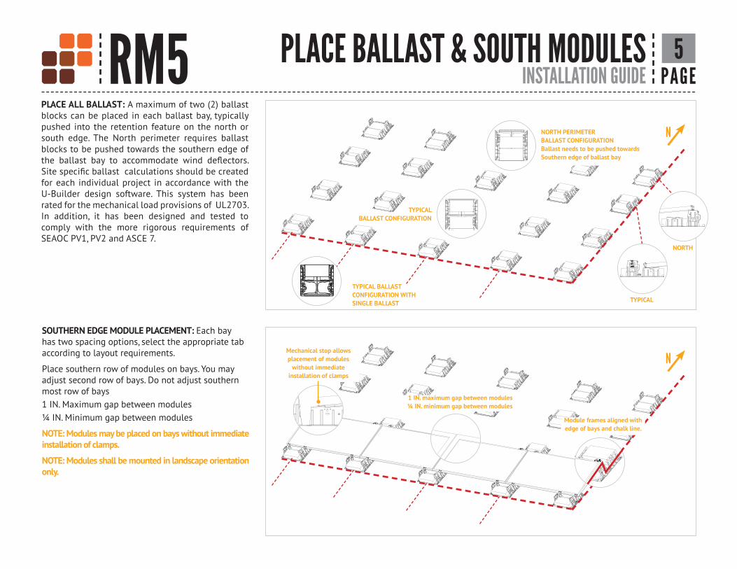
INSTALLATION GUIDE PAGERM5 PLACE BALLAST & SOUTH MODULES 5
SOUTHERN EDGE MODULE PLACEMENT: Each bay has two spacing options, select the appropriate tab according to layout requirements.
Place southern row of modules on bays. You may adjust second row of bays. Do not adjust southern most row of bays 1 IN. Maximum gap between modules ¼ IN. Minimum gap between modules
NOTE: Modules may be placed on bays without immediate installation of clamps.
NOTE: Modules shall be mounted in landscape orientation only.
N
N
Module frames aligned with edge of bays and chalk line.
1 IN. maximum gap between modules ¼ IN. minimum gap between modules
Mechanical stop allows placement of modules
without immediate installation of clamps
TYPICALBALLAST CONFIGURATION
PLACE ALL BALLAST: A maximum of two (2) ballast blocks can be placed in each ballast bay, typically pushed into the retention feature on the north or south edge. The North perimeter requires ballast blocks to be pushed towards the southern edge of
for each individual project in accordance with the U-Builder design software. This system has been rated for the mechanical load provisions of UL2703. In addition, it has been designed and tested to comply with the more rigorous requirements of SEAOC PV1, PV2 and ASCE 7.
NORTH PERIMETERBALLAST CONFIGURATIONBallast needs to be pushed towardsSouthern edge of ballast bay
TYPICAL BALLASTCONFIGURATION WITHSINGLE BALLAST TYPICAL
NORTH

INSTALLATION GUIDE PAGE RM5 MODULE PLACEMENT & ATTACH CLAMPS 6
INSTALL U-NUT & INSTALL CLAMPSNOTE: U-NUT - Single Use Only - Do not re-torque once fully seatedNOTE: CLAMP AND BOLT - Single Use Only - Do not re-torque once fully seatedTORQUE VALUE: 7FT-LBS MINIMUM to achieve UL2703 required clamp load
PROPER CLAMP INSTALLATION:
• Clamp is stamped for module frame height on each leg
while being torqued
PROBLEM – CLAMP NOT SEATED AGAINST MODULE DURING TORQUING
• Clamp needs to be held securely against the module frame during torquing for proper installation
PROBLEM – NOT USING PROPER SIZE OF CLAMP FOR MODULE FRAME HEIGHT• Double check the stamping on clamp to use the correct leg of clamp for module frame height
• The module height shall fall within the range shown on the top of the clamp
• Excessive angle on clamp will inhibit required clamp load on module
1/4"-20 Stainless Steel U-Nut
Physical contact must be maintained on alignment
tabs as bolt is torqued
Apply Pressure here to
module frame
Module Frame Heightmust fall within proper
range stamped on clamp
Clamp installed with improper range for module height
No gap should be present while torquing clamp down to
EAST OR WEST EDGE MODULE PLACEMENT
NOTE: Modules may be placed on bays without immediate installation of clamps.
NOTE: Modules shall be mounted in landscape orientation only.
COMPLETE MODULE PLACEMENT
1/4"-20 x 2 1/2 IN. Stainless Steel Bolt &End Clamp

INSTALLATION GUIDE - SUPPLEMENT PAGE RM5 BALLAST BAY WIND DEFLECTORS 7
STEP 1 - U-NUTS: STEP - 2 WIND DEFLECTOR: Position wind STEP 3 - HARDWARE:
aboveTORQUE VALUE: 10FT-LBS
INSTALL BALLAST BAY WIND DEFLECTORS

INSTALLATION GUIDE PAGERM5 CONNECT GROUNDING LUG 8Ils
co S
GB-4
Sol
ar G
roun
ding
& B
ondi
ngIls
co S
GB-4
Sol
ar G
roun
ding
& B
ondi
ng
GROUNDING LUG MOUNTING DETAILS AS REQUIRED BY CODE & ENGINEER OF RECORD: The Ilsco lug has a green colored set screw for grounding indication purposes. One lug is recommended per continuous array, not to exceed 150ft X 150ft.
Unirac ROOFMOUNT is intended to be used with PV modules that have a system voltage less than or equal to that allowable by the National Electric Code (NEC). It is the installer's responsibility to check adherence to local codes.
NOTE: The installation must be conducted in accordance with the National Electric Code ANSI / NFPA 70.
TERMINAL TORQUE:Install conductor and torque to the following: 4-14 AWG: 35 in-lbs
GROUNDING NOTE:Can be installed on any location with a
bay in order to ground the system.
Ground Lug Bolt Size Torque Value
Ilsco Lug 1/4"-20 6.5 ft-lbs (75 in-lbs)
NOTE: In order to prevent corrosion induced by dissimilar metals, it is important to verify that the bare copper wire does not come into contact with aluminum or galvanized steel. These materials must be kept separate.
Although conformance with UL2703 was demonstrated without the use of oxide inhibitor material, it is recommended by Ilsco to provide an optimized bonding solution for their lay-in lug.

INSTALLATION GUIDE PAGE RM5 MECHANICAL LOADING COMPLIANCE 9
MECHANICAL LOAD TEST QUALIFICATION
The Unirac RM system has been tested to the mechanical load provisions of UL2703 and covers the following basic parameter(s):
• Tested loads: 25 psf up, 54 psf down
•
TESTED MODULEModule Manufacturer Model / Series
Hyundai HIS-S325TI

INSTALLATION GUIDE PAGE RM5 SYSTEM CERTIFICATION 10BONDING & GROUNDING
VERIFIED COMPATIBLE MODULES:
Manufacture Module Model / Series CellsFrame Height (MM)
Aleo P18 & P19 60 35
Aleo S18, S19, S59, & S79 60 50
AU Optronics PM Series 60 40
AU Optronics PM Series 72 40
Auxin AXN6M610Txxx 60 40
Auxin AXN6P610Txxx 60 40
Auxin AXN6M612Txxx 72 40
Auxin AXN6P612Txxx 72 40
Canadian Solar CS5A-M & CS6P-M 60 40
Canadian Solar CS6X-P, CS6U-P, & CS6U-M 72 40
Canadian Solar CS6K-MS & CS6K-M 60 40
Canadian Solar CS6K-P & CS6P-P 60 40
Canadian Solar CS3U-P & CS3U-MS 72 40
Canadian Solar CS3K-P & CS3K-MS 60 40
Centrosolar America C-Series & E-Series 60/72 40
CertainTeed CT2xxMxx-01 60 35
CertainTeed CT2xxPxx-01 60 35
CertainTeed CTxxxMxx-01 72 40
CertainTeed CTxxxPxx-01 72 40
CertainTeed CTxxxMxx-02 60/72 40
ET Solar ETAC & ET Modules 60/72 40
Eco Solargy Orion 1000 ECOxxx156P 60 40
Hanwha SolarOne HSL 60 & HSL 72 60/72 40
Heliene 36M Series 36 40
Heliene 60M Series 60 40
Heliene 72M Series 72 40
Hyundai Heavy Industries MG, TG, RG, & KG Series 60 35
Hyundai Heavy Industries TI & RI Series 72 50
Hyundai Heavy Industries MI, RI, KI, & TI Series 72 40
JA Solar JAP6 60 & JAM6 60 60 40
JA Solar JAP6 72 & JAM6 72 72 45
Manufacture Module Model / Series CellsFrame Height (MM)
Jinko JKMxxxM & JKMxxxP 60 40
Jinko JKMxxxPP & JKMSxxxPP 60 40
Jinko JKMxxxP 72 40
Jinko JKMSxxxP 60 40
Kyocera KD-F Series 60 46
LG Electronics MONO X 60 35
LG Electronics MONO X 2 60 40
LG Electronics MONO X Plus 60/72 40
LG Electronics NeON 2/2 Black 60 40
LG Electronics NeON 2 72 40/46
LG Electronics NeON R/R Black (Black Contact) 60 40
LG Electronics NeON 2 Bifacial 72 40
LG Electronics MONO X 72 46
LG Electronics NeON 2 AC 60 40
Mission Solar Energy MSE MONO & MSE PERC 60/72 40
Mitsubishi MJE Series 60 46
Mitsubishi MLE Series 120 46
Phono Solar Tech. Standard Modules 60 40
Phono Solar Tech. Standard Modules 72 45
Panasonic VBHNxxxSA15 96 35
Panasonic VBHNxxxSA16 96 35
Panasonic VBHNxxxKA01 96 35
Panasonic VBHNxxxKA02 96 35
Q.Cells Q.PLUS/PEAK/PRO - L G4.x 72 35
Q.Cells B.LINE PLUS/PRO - L G4.x 72 35
Q.Cells Q.PLUS L-G4.2/TAA 72 35
Q.Cells Q.PRO L-G2 xxx 72 40/42
Q.Cells Q.PLUS BFR G4.1 60 32
Q.Cells Q.PRO BFR G4x 60 32
Q.Cells Q.PEAK-G4.1 60 32
Q.Cells Q.PEAK-G4.1/MAX 60 32
Manufacture Module Model / Series CellsFrame Height (MM)
Q.Cells Q.PEAK BLK G4.1 60 32
Q.Cells Q.PRO/Q.PLUS G4 60 32
Q.Cells Q.PEAK-G4.1/TAA 60 32
Q.Cells Q.PEAK BLK G4.1/TAA 60 32
Q.Cells Q.PLUS BFR G4.1/TAA 60 32
Q.Cells Q.PLUS BFR G4.1/MAX 60 32
Q.Cells B.LINE PLUS BFR G4.1 60 32
Q.Cells B.LINE PRO BFR G4.1 60 32
Q.Cells Q.PRO EC-G4.4 60 32
Q.Cells Q.PEAK-G3 & G3.1 60 35
Q.Cells Q.PEAK BLK G3 & G3.1 60 35
Q.Cells Q.PLUS BFR G3.1 60 35
Q.Cells Q. PLUS G3 & Q.PRO G3 60 35
REC PEAK & ECO 60 38
REC PE 72 72 45
Renesola 60 Cell Modules & Vitrus2 60/72 40
Sharp ND-24CQCJ & ND-25CQCS 60 46
Sharp ND-Q235F4 &ND-F4Q300 60 46
Sharp NU-SA 60 35
Sharp NU-SC 72 40
Silfab SLA-M/P 60 38
SolarWorld Sunmodule Protect/Plus 60/72 33
Suniva Optimus Series 60 60 35
Suniva Optimus Series 72 72 38
Suniva MV Series 60 60 40
Suniva MV Series 72 72 46
Suntech STP "XXX" 60 35
Suntech STP "XXX" 72 40
Sun Edison/Flextronics F-Series / FLEX FXS 60 35/50
Sun Edison/Flextronics R-Series / FLEX FXS 72 35/50
SunPower X-Series 72 & E-Series 72 72 46
ELECTRICAL BONDING & GROUNDING TEST MODULES: This racking system may be used to ground and/or mount a PV module complying with UL 1703 only when

INSTALLATION GUIDE PAGE RM5 SYSTEM CERTIFICATION 11BONDING & GROUNDING
VERIFIED COMPATIBLE MODULES (CONTINUED):
Manufacture Module Model / Series CellsFrame Height (MM)
SunPower X-Series 96 & E-Series 96 96 46
SunPower P-Series 498 46
SunPower Sig Black 72 72 46
SunPower Sig Black 96 96 46
SunPower AC 60 46
Trina PA05, PD05, & DD05 60 35
Trina PD14, PE14, & DD14 72 40
Yingli YGE-U72 72 40
Yingli Panda 60 60 40
Yingli DS YGE 60 Cell Series 60 40
Yingli DS YGE 60 Cell Series 2 60 35
ELECTRICAL BONDING & GROUNDING TEST MODULES: This racking system may be used to ground and/or mount a PV module complying with UL 1703 only when

INSTALLATION GUIDE PAGE RM5 12ELECTRICAL DIAGRAMBONDING & GROUNDING
Fault Current Ground Path
Ground Lug
Grounding Clip & Bolt
Min. 10 AWG Copper Wire
Module FrameModule Bay w/ Grounding Clips

INSTALLATION GUIDE PAGERM5 TEMPORARY BONDING PROCEDURES 13
ATTACH LUGS: Use approved lug(s) to install on adjacent bays where the module is being removed.
INSERT COPPER WIRE: Insert bare copper wire into each lug, providing a bonding jumper across the missing module location.
Bare Copper Wire
REMOVE MODULE & REVERSE THE OPERATION AFTER MAINTENANCE IS COMPLETENOTE: CLAMP AND BOLT - Single Use Only - Use new clamps after any module replacements or system maintenance.
TEMPORARY GROUNDING & BONDING PROCEDURE: Periodic inspections should be conducted on the PV array to ensure there are not loose components, loose fasteners or corrosion. If any of the above items are found, the affected components are to be immediately replaced. If a module must be removed or replaced, a temporary bonding jumper must be used to ensure safety of the personnel and PV system.
NOTE: Removing a PV module from a system is not considered to be routine maintenance. This type of activity should only be performed by trained and
NOTE: In order to prevent corrosion induced by dissimilar metals, it is important to verify that the bare copper wire does not come into contact with aluminum or galvanized steel. These materials must be kept separate.
APPROVED LUGS:Ilsco lay-in Lug Ilsco - SGB-4
TERMINAL TORQUE: Install conductor and torque to the following: 4-14 AWG: 35in-lbs

INSTALLATION GUIDE - SUPPLEMENT PAGE RM5 BALLAST BAY ROOF ATTACHMENT A
STEP 1 - POSITION ROOF ATTACHMENT: Position Roof Attachment under bay requiring attachment and install according to manufacturer installation instructions. NOTE: Center roof attachment under ballast bay as close as possible.
BASE OF ATTACHMENT
STEP 3 - SECURE UNISTRUT TO ROOF ATTACHMENT: Place 3/8” washer and 3/8-16
down and tighten to 30 ft-lb.TORQUE VALUE: 30FT-LBS
STEP 2 - PLACE UNISTRUT: Place Unistrut across bay with the anchor stud through a slot.
NOTE: Metal base of attachment where stud is located cannot exceed a height of 1/4".

INSTALLATION GUIDE - SUPPLEMENT PAGERM5 BMICROINVERTER INSTALL & WIRE MGMT.
PRE-INSTALL MICROINVERTERS: Install MLPE in a location on the module that will not interfere with ballast bays or grounding lugs. To use trunk cable
same locations on all modules in the same row.TORQUE VALUE: 20FT-LBS