Embed Size (px)
Citation preview
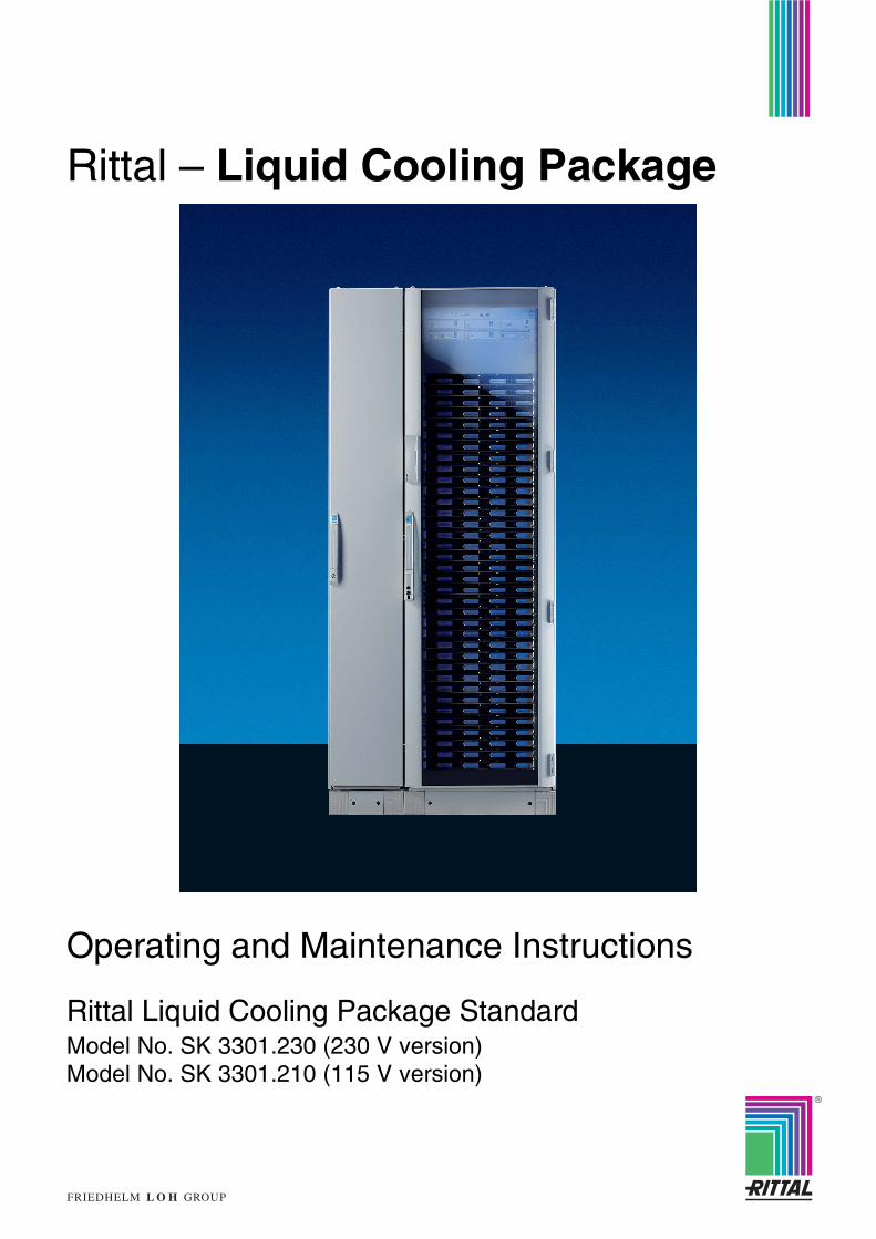
Rittal – Liquid Cooling Package
Operating and Maintenance Instructions
Rittal Liquid Cooling Package StandardModel No. SK 3301.230 (230 V version)Model No. SK 3301.210 (115 V version)
2 Operating and Maintenance Instructions
Rittal Liquid Cooling Package StandardForeword Dear Customer!
We would like to thank you for choosing our Rittal Liquid Cooling Package Standard (referred to hereafter simply as "Liquid Cooling Package" or LCP).
Please take the time to read this documentation carefully.
Please pay particular attention to the safety instructions in the text and to Chapter 2, "Safety instructions".
This is the prerequisite for:- secure assembly of the Liquid Cooling Package,
- safe handling and
- the most trouble-free operation possible.
Please keep the complete documentation readily available so that it is always on hand when needed.
We wish you every success!
YourRittal GmbH & Co. KG
Rittal GmbH & Co. KGAuf dem Stützelberg
35745 HerbornGermany
Tel.: +49 (0) 27 72/50 5-0Fax: +49 (0) 27 72/50 5-23 19
E-mail: [email protected]
We are always happy to answer any technical questions regarding our entire range of products.
Rittal Liquid Cooling Package Standard
Table of contentsForeword ................................................................................. 2Table of contents ................................................................... 3
1 Identification ........................................................................... 51.1 Manufacturer ........................................................................................ 51.2 Notes concerning the documentation ................................................... 51.2.1 Other applicable documents ................................................................. 51.2.2 CE labelling .......................................................................................... 51.2.3 Nameplate ............................................................................................ 61.2.4 Storing the documents ......................................................................... 61.2.5 Legal information concerning the operating instructions ...................... 61.2.6 Copyright .............................................................................................. 61.2.7 Revision ................................................................................................ 61.3 Product description ............................................................................... 71.3.1 Unit components .................................................................................. 71.3.2 Proper use ............................................................................................ 81.3.3 Precautionary measures ...................................................................... 8
2 Safety instructions ................................................................. 92.1 Symbols in these operating instructions ............................................... 92.2 Important safety instructions ................................................................ 92.3 Service and technical staff ................................................................. 102.4 RoHS compliance ............................................................................... 11
3 Transport and handling ....................................................... 123.1 Scope of delivery ................................................................................ 123.1.1 Liquid Cooling Package ...................................................................... 123.1.2 LCP module ........................................................................................ 123.2 Transport ............................................................................................ 133.3 Unpacking .......................................................................................... 13
4 Design and function ............................................................. 144.1 Design ................................................................................................ 144.1.1 Liquid Cooling Package ...................................................................... 154.1.2 LCP module ........................................................................................ 174.1.3 Water module with cold water connection .......................................... 194.2 Function .............................................................................................. 214.3 Air routing inside the enclosure .......................................................... 244.4 Possible module configurations .......................................................... 264.4.1 Cooling with one module .................................................................... 264.4.2 Cooling with two modules ................................................................... 274.4.3 Cooling with three modules ................................................................ 284.4.4 Possibilities for establishing redundancies ......................................... 29
5 Technical specifications ...................................................... 32
6 Installation – "Getting Started" ........................................... 336.1 Installation conditions ......................................................................... 336.2 Assembling the Liquid Cooling Package ............................................ 346.2.1 Preparatory work on the server enclosure ......................................... 346.2.2 Removing the transport clamps .......................................................... 376.2.3 Installation and baying of the Liquid Cooling Package ....................... 386.2.4 Assembly of the side panel on the Liquid Cooling Package ............... 406.3 Assembly of an LCP module .............................................................. 416.3.1 Removal of an LCP module ............................................................... 416.3.2 Installation of an LCP module ............................................................ 436.4 Connecting the Liquid Cooling Package ............................................ 476.4.1 Electrical connection .......................................................................... 476.4.2 Cooling water connection ................................................................... 48
3 Operating and Maintenance Instructions – Table of contents
Rittal Liquid Cooling Package Standard
6.4.3 Condensate discharge connection ..................................................... 506.5 Cooling operation and control behaviour ............................................ 536.5.1 Cooling output .................................................................................... 536.5.2 Pressure loss ...................................................................................... 546.6 Operation ............................................................................................ 566.7 Extended options by connecting a Computer Multi Control –Top Concept (CMC-TC) ..................................................................... 596.7.1 Visualisation ....................................................................................... 61
7 Hardware and software ........................................................ 727.1 Liquid Cooling Package control unit ................................................... 727.1.1 Hardware ............................................................................................ 727.2 Control unit for fan module (RLCP-Fan) ............................................. 747.2.1 Hardware ............................................................................................ 747.2.2 Software ............................................................................................. 757.2.3 Control unit for water module (RLCP-Water) ..................................... 767.3 Hardware ............................................................................................ 767.3.1 Software ............................................................................................. 77
8 Maintenance ......................................................................... 79
9 Troubleshooting ................................................................... 80
10 Frequently asked questions (FAQ) ..................................... 82
11 Glossary ................................................................................ 87
12 Spare parts ........................................................................... 89
13 Accessories .......................................................................... 9013.1 Accessories Liquid Cooling Package ................................................. 9013.2 Accessories from the rack program .................................................... 90
14 Further technical information ............................................. 9114.1 Hydrological information ..................................................................... 9114.2 Characteristic curves .......................................................................... 9214.2.1 Cooling output .................................................................................... 9214.2.2 Pressure loss ...................................................................................... 9414.3 Overview diagram .............................................................................. 9614.4 Circuit diagram ................................................................................... 9814.5 Wiring diagrams ................................................................................. 9914.6 Water circulation diagram ................................................................. 102
Appendix 1 Installation checklist ................................................. 103
Appendix 2 Preparation and maintenance of the water in recooling systems .................................................... 107
4 Operating and Maintenance Instructions – Table of contents
Rittal Liquid Cooling Package Standard
1 Identification1.1 Manufacturer
1.2 Notes concerning the documentation
1.2.1 Other applicable documents In conjunction with these operating and maintenance instructions, the superordinate system documentation (if available) also applies.
Rittal GmbH & Co. KG is not responsible for any damage which may result from failure to comply with these operating and maintenance instructions. This also applies to failure to comply with the valid documentation for accessories used.
1.2.2 CE labelling With the EU declaration of conformity, Rittal GmbH & Co. KG, the manufacturer, certifies that the cooling units of the Liquid Cooling Package series are manufactured and tested in accordance with the following directives:- EU EMC directive 89/336/EEC (annex 92/31EC and 93/68/EC)
- EU Low Voltage Directive 73/23/EEC (annex 93/68/EC)
- EN 55022Information technology equipment - Radio disturbance characteristics
- EN 60204Safety of machinery - Electrical equipment of machines
- EN 60950Safety of information technology equipment
- EN 61000 3-2Electromagnetic compatibility (EMC)Part 3-2: Limits - Limits for harmonic current emissions (equipment input current up to and including 16 A per phase)
- EN 61000 6-2Electromagnetic compatibility (EMC)Part 6-2: Generic standards - Immunity for industrial environments
- EN 61000 6-3Electromagnetic compatibility (EMC)Part 6-3: Generic standards - Emission standard for residential, commercial and light-industrial environments
The cooling unit bears the following mark.
Manufacturer Rittal GmbH & Co. KG
Address: Auf dem Stützelberg
City: 35745 HerbornGermany
Telephone: +49 (0) 27 72/50 5-0
Telefax: +49 (0) 27 72/50 5-23 19
E-mail: [email protected]
Internet: www.rimatrix5.com
5 Operating and Maintenance Instructions – 1 Identification
Rittal Liquid Cooling Package Standard
1.2.3 NameplateFig. 1: Nameplate
1.2.4 Storing the documents The operating and maintenance instructions as well as all applicable documents are integral components of the product. They must be handed out to those persons who are engaged with the unit and must always be available and on hand for operating and maintenance personnel.
1.2.5 Legal information concerning the operating instructions
We reserve the right to make changes in content. Rittal GmbH & Co. KG is not responsible for mistakes in this documentation. Liability for indirect damages which occur through the delivery or use of this documentation is excluded to the extent allowable by law.
1.2.6 Copyright The distribution and duplication of this document and the disclosure and use of its contents are prohibited unless expressly authorised.Offenders will be liable for damages. All rights created by a patent grant or registration of a utility model or design are reserved.
1.2.7 Revision Rev. 0 of 21 July 2006
SK 3301 230
C USR
Protective category
Year of constructionFabr.-Nr.:Production No.
Baujahr
GewichtWeight
SchutzartEN 60529
Noise levelIP30
160 kg (350 pounds)
:
:
:
4,0/3,5 kW
Rated voltage
Nominal refrigeration
Useful cooling output l/h
Geräuschpegel
Nennleistung
Nutzkühlleistung L37 W15capacity
Nennstrom
Vorsicherung TRated current
Pre-fuse T
58 dB(A):
360/400 W
1,9/2,0 A
6 A
:
:
:
:
Luft/Wasser-WärmetauscherAir/water heat exchanger
Echangeur de temperature air/eauLucht/Water-WarmtewisselaarLuft/vatten vaermevaexlare
Scambiatore di calore ad aria/acqua
Intercambiador de calor aire/agua
Nennspannung : 230V 50/60Hz
WA ----- / ---
1x Modul
2,9/3,2 A
2x Module
3,8/4,4 A
3x Module
615/715 W 865/1025 W
8,0/7,0 kW 12,0/10,5 kW
6 A 10 A
930 l/h 1860 l/h 2790 l/h
Wasser (siehe Spezifikation)Water (see specification)
KühlmediumCoolant
+6˚C bis to +40˚C (+43˚F to +104˚F)
2-5 bar (29-73 psi)
:
:
:PS H O2
POH O2
8 bar (116 psi):PT H O2 12 bar (174 psi):
TOAir
+6˚C bis to +40˚C (+43˚F to +104˚F):TS Air
35745 Herborn
RITTAL
GmbH & Co.KGAuf dem Stützelberg
6 Operating and Maintenance Instructions – 1 Identification
Rittal Liquid Cooling Package Standard
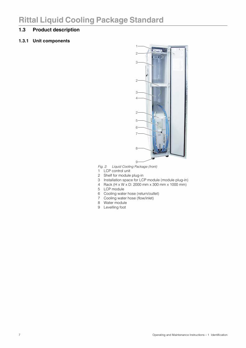
1.3 Product description1.3.1 Unit components
Fig. 2: Liquid Cooling Package (front)1 LCP control unit2 Shelf for module plug-in3 Installation space for LCP module (module plug-in)4 Rack (H x W x D: 2000 mm x 300 mm x 1000 mm)5 LCP module6 Cooling water hose (return/outlet)7 Cooling water hose (flow/inlet)8 Water module9 Levelling foot
6
3
4
2
2
5
7
8
9
2
3
1
7 Operating and Maintenance Instructions – 1 Identification
Rittal Liquid Cooling Package Standard
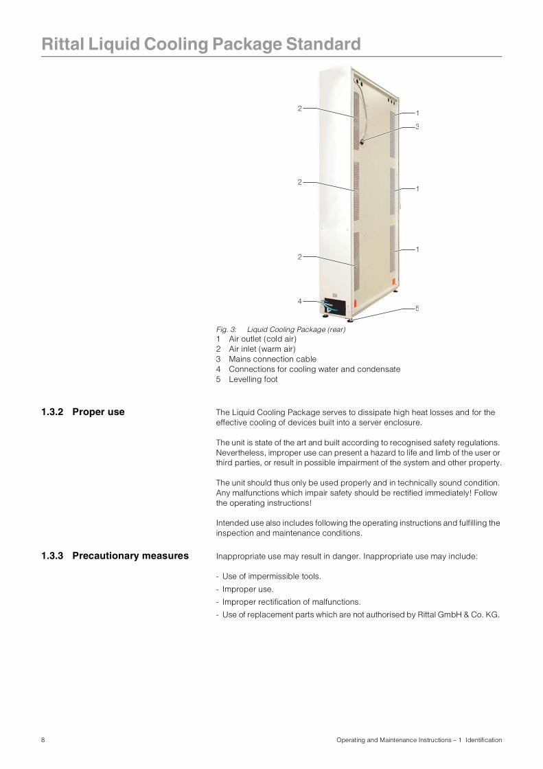
Fig. 3: Liquid Cooling Package (rear)1 Air outlet (cold air)2 Air inlet (warm air)3 Mains connection cable4 Connections for cooling water and condensate5 Levelling foot
1.3.2 Proper use The Liquid Cooling Package serves to dissipate high heat losses and for the effective cooling of devices built into a server enclosure.
The unit is state of the art and built according to recognised safety regulations. Nevertheless, improper use can present a hazard to life and limb of the user or third parties, or result in possible impairment of the system and other property.
The unit should thus only be used properly and in technically sound condition. Any malfunctions which impair safety should be rectified immediately! Follow the operating instructions!
Intended use also includes following the operating instructions and fulfilling the inspection and maintenance conditions.
1.3.3 Precautionary measures Inappropriate use may result in danger. Inappropriate use may include:
- Use of impermissible tools.
- Improper use.
- Improper rectification of malfunctions.
- Use of replacement parts which are not authorised by Rittal GmbH & Co. KG.
3
4
2
2
1
1
12
5
8 Operating and Maintenance Instructions – 1 Identification
Rittal Liquid Cooling Package Standard
2 Safety instructions The Liquid Cooling Packages (LCP) produced by Rittal GmbH & Co. KG aredeveloped and produced with due regard to all safety precautions. Nevertheless, the unit still causes a number of unavoidable dangers and risks. The safety instructions provide you with an overview of these dangers and the necessary safety precautions. In the interest of your safety and the safety of others, please read these safety instructions carefully before assembly and commissioning of the Liquid Cooling Package.Follow the user information found in these instructions and on the unit carefully.
2.1 Symbols in these operating instructions
These following symbols are found in this documentation:
• This symbol indicates an "Action Point" and shows that you should carry out an operation/procedure.
2.2 Important safety instructions
Danger!
This warning symbol is used to indicate great dangers caused by the product which may result in injury and even death if the indicated preventative measures are not followed.
Caution!
This warning symbol is used to indicate procedures which may cause risk of equipment damage or personal injury.
Note:
This instruction symbol indicates information concerning individual procedures, explanations, or tips for simplified approaches.
Danger! Electric shock!
Contact with live electrical parts may be deadly.
Shut off power before opening doors or covers! Before switching on, ensure that it is not possible to come into contact with live electrical parts.
Danger! Injury caused by fan impellors!
Keep persons and objects away from the fan impellors! Do not remove covers until the power supply is disconnected and impellors are not moving! Always use mechanical protection when working! Shut down the respective fan as much as possible during maintenance work! Tie long hair back! Do not wear loose clothing!
Fans start up automatically following power disruptions!
Danger! Cut wounds, especially through sharp edges of the fan module and heat exchanger modules!
Put on protective gloves before beginning assembly or cleaning work!
9 Operating and Maintenance Instructions – 2 Safety instructions
Rittal Liquid Cooling Package Standard
2.3 Service and technical staff The installation, commissioning, maintenance and repair of this unit may only be carried out by qualified mechanical and electro-technical trained personnel.Only properly instructed personnel may carry out service on a unit while in operation.
Danger! Injury due to falling loads!
Do not stand under suspended loads when transporting the unit with a hoist trolley, a forklift, or a crane.
Caution! Risk of malfunction or damage!
Do not modify the unit! Use only original spare parts!
Caution! Risk of malfunction or damage!
Proper and flawless unit operation can only be ensured when it is operated under the intended ambient conditions. As far as possible, be sure that the ambient conditions for which the unit is designed are complied with, e.g. temperature, humidity, air purity.
Caution! Risk of malfunction or damage!
All media necessary for the control system, e.g. cooling water, must be available during the entire operating time.
Caution! Risk of malfunction or damage!
In order to avoid frost damage, the minimum permissible input water temperature of +6 °C must not be undercut at any point in the water cycle!
It is vital that the manufacturers’ consent is obtained before adding anti-freeze!
Caution! Risk of malfunction or damage!
During storage and transportation below freezing point, the water cycle should be drained completely using compressed air!
Caution! Risk of malfunction or damage!
Only set the temperature control setpoint as low as is strictly necessary, since the danger of condensation through undercutting the dew point increases with a falling water inlet temperature!
Ensure that the enclosure is sealed on all sides, particularly at the cable entry (condensation)!
10 Operating and Maintenance Instructions – 2 Safety instructions
Rittal Liquid Cooling Package Standard
2.4 RoHS compliance The Liquid Cooling Package fulfils the requirements of EU directive 2002/95/ECon the Restriction of Use of Certain Hazardous Substances in Electrical and Electronic Equipment (RoHS) of 13 February, 2003.
Note:
Corresponding information concerning the RoHS directive is provided by our firm on the Internet at www.rittal.de/RoHS.
11 Operating and Maintenance Instructions – 2 Safety instructions
Rittal Liquid Cooling Package Standard
3 Transport andhandling
3.1 Scope of delivery
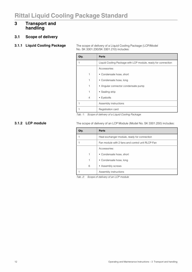
3.1.1 Liquid Cooling Package The scope of delivery of a Liquid Cooling Package (LCP/Model No. SK 3301.230/SK 3301.210) includes:
Tab. 1: Scope of delivery of a Liquid Cooling Package
3.1.2 LCP module The scope of delivery of an LCP Module (Model No. SK 3301.250) includes:
Tab. 2: Scope of delivery of an LCP module
Qty. Parts
1 Liquid Cooling Package with LCP module, ready for connection
Accessories:
1 • Condensate hose, short
1 • Condensate hose, long
1 • Angular connector condensate pump
1 • Sealing strip
4 • Eyebolts
1 Assembly instructions
1 Registration card
Qty. Parts
1 Heat exchanger module, ready for connection
1 Fan module with 2 fans and control unit RLCP-Fan
Accessories:
1 • Condensate hose, short
1 • Condensate hose, long
6 • Assembly screws
1 Assembly instructions
12 Operating and Maintenance Instructions – 3 Transport and handling
Rittal Liquid Cooling Package Standard
3.2 Transport The Liquid Cooling Package is delivered shrink-wrapped on a pallet.3.3 Unpacking • Remove the unit's packaging materials.
• Check the unit for damages occurring in transport.
• Place the unit in its intended location.
Caution!
Because of its height and small base, the Liquid Cooling Package is subject to tipping. Risk of toppling, especially after the unit is removed from the pallet!
Caution!
Transport of the Liquid Cooling Package without a pallet:
- Use only suitable and technically sound lifting gear and load-bearing devices with sufficient load capacity.
Note
After unpacking, the packaging materials must be disposed of in an environmentally friendly way. They may consist of the following materials:- Wood,
- Polyethylene film (PE film),
- Strap,
- Edge protectors.
Note
Damage and other faults, e.g. incomplete delivery, should immediately be reported to the shipping company and to Rittal GmbH & Co. KG in writing.
13 Operating and Maintenance Instructions – 3 Transport and handling
Rittal Liquid Cooling Package Standard
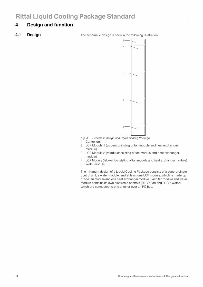
4 Design and function4.1 Design The schematic design is seen in the following illustration:
Fig. 4: Schematic design of a Liquid Cooling Package1 Control unit2 LCP Module 1 (upper/consisting of fan module and heat exchanger
module) 3 LCP Module 2 (middle/consisting of fan module and heat exchanger
module) 4 LCP Module 3 (lower/consisting of fan module and heat exchanger module) 5 Water module
The minimum design of a Liquid Cooling Package consists of a superordinate control unit, a water module, and at least one LCP module, which is made up of one fan module and one heat exchanger module. Each fan module and water module contains its own electronic controls (RLCP-Fan and RLCP-Water), which are connected to one another over an I2C bus.
5
3
4
2
1
14 Operating and Maintenance Instructions – 4 Design and function
Rittal Liquid Cooling Package Standard
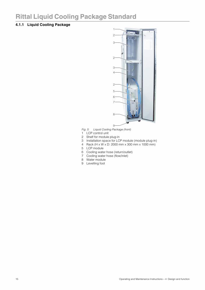
4.1.1 Liquid Cooling PackageFig. 5: Liquid Cooling Package (front)1 LCP control unit2 Shelf for module plug-in3 Installation space for LCP module (module plug-in)4 Rack (H x W x D: 2000 mm x 300 mm x 1000 mm)5 LCP module6 Cooling water hose (return/outlet)7 Cooling water hose (flow/inlet)8 Water module9 Levelling foot
6
3
4
2
2
5
7
8
9
2
3
1
15 Operating and Maintenance Instructions – 4 Design and function
Rittal Liquid Cooling Package Standard
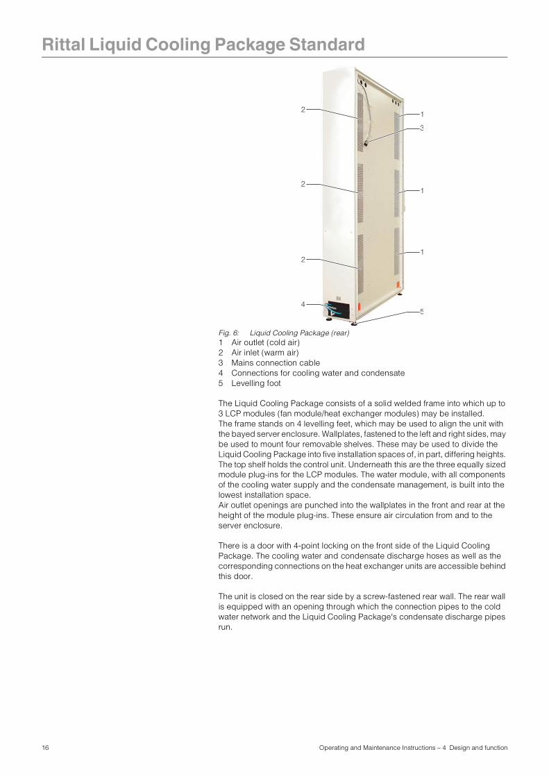
Fig. 6: Liquid Cooling Package (rear)1 Air outlet (cold air)2 Air inlet (warm air)3 Mains connection cable4 Connections for cooling water and condensate5 Levelling foot
The Liquid Cooling Package consists of a solid welded frame into which up to 3 LCP modules (fan module/heat exchanger modules) may be installed.The frame stands on 4 levelling feet, which may be used to align the unit with the bayed server enclosure. Wallplates, fastened to the left and right sides, may be used to mount four removable shelves. These may be used to divide the Liquid Cooling Package into five installation spaces of, in part, differing heights. The top shelf holds the control unit. Underneath this are the three equally sized module plug-ins for the LCP modules. The water module, with all components of the cooling water supply and the condensate management, is built into the lowest installation space. Air outlet openings are punched into the wallplates in the front and rear at the height of the module plug-ins. These ensure air circulation from and to the server enclosure.
There is a door with 4-point locking on the front side of the Liquid Cooling Package. The cooling water and condensate discharge hoses as well as the corresponding connections on the heat exchanger units are accessible behind this door.
The unit is closed on the rear side by a screw-fastened rear wall. The rear wall is equipped with an opening through which the connection pipes to the cold water network and the Liquid Cooling Package's condensate discharge pipes run.
3
4
2
2
1
1
12
5
16 Operating and Maintenance Instructions – 4 Design and function
Rittal Liquid Cooling Package Standard
4.1.2 LCP module An LCP module consists of a heat exchanger module and a fan module, whichare installed successively in one of the three module plug-ins in the Liquid Cooling Package.
Heat exchanger module
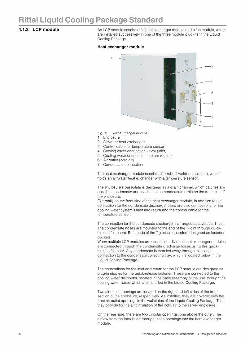
Fig. 7: Heat exchanger module1 Enclosure2 Air/water heat exchanger3 Control cable for temperature sensor4 Cooling water connection – flow (inlet)5 Cooling water connection – return (outlet)6 Air outlet (cold air)7 Condensate connection
The heat exchanger module consists of a robust welded enclosure, which holds an air/water heat exchanger with a temperature sensor.
The enclosure's baseplate is designed as a drain channel, which catches any possible condensate and leads it to the condensate drain on the front side of the enclosure.Externally on the front side of the heat exchanger module, in addition to the connection for the condensate discharge, there are also connections for the cooling water system's inlet and return and the control cable for the temperature sensor.
The connection for the condensate discharge is arranged as a vertical T-joint. The condensate hoses are mounted to the end of the T-joint through quick-release fasteners. Both ends of the T-joint are therefore designed as fastener pockets.When multiple LCP modules are used, the individual heat exchanger modules are connected through the condensate discharge hoses using this quick-release fastener. Any condensate is then led away through this series connection to the condensate collecting tray, which is located below in the Liquid Cooling Package.
The connections for the inlet and return for the LCP module are designed as plug-in nipples for the quick-release fastener. These are connected to the cooling water distributor, located in the base assembly of the unit, through the cooling water hoses which are included in the Liquid Cooling Package.
Two air outlet openings are located on the right and left sides of the front section of the enclosure, respectively. As installed, they are covered with the front air outlet openings in the wallplates of the Liquid Cooling Package. Thus, they provide for the air circulation of the cold air to the server enclosure.
On the rear side, there are two circular openings, one above the other. The airflow from the fans is led through these openings into the heat exchanger module.
3
1
5
2
4
6
7
17 Operating and Maintenance Instructions – 4 Design and function
Rittal Liquid Cooling Package Standard
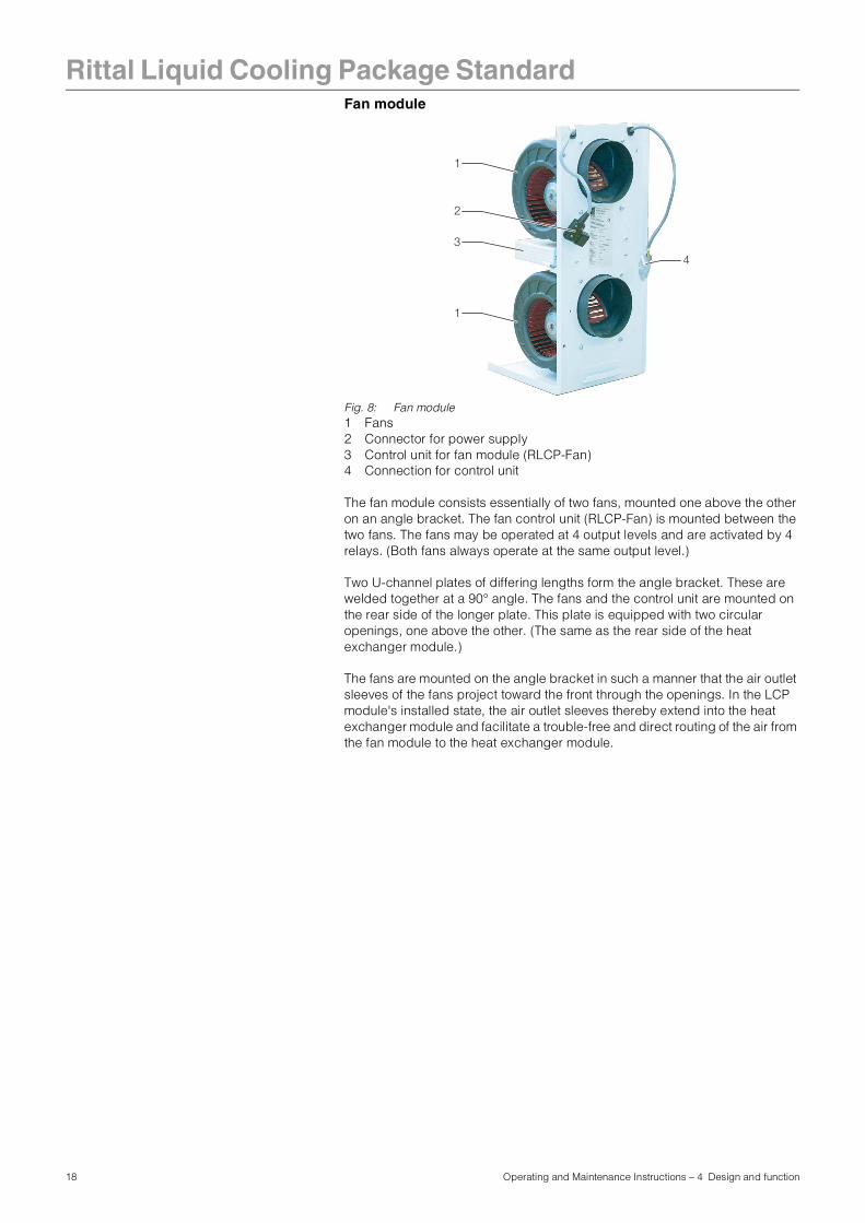
Fan moduleFig. 8: Fan module1 Fans2 Connector for power supply3 Control unit for fan module (RLCP-Fan)4 Connection for control unit
The fan module consists essentially of two fans, mounted one above the other on an angle bracket. The fan control unit (RLCP-Fan) is mounted between the two fans. The fans may be operated at 4 output levels and are activated by 4 relays. (Both fans always operate at the same output level.)
Two U-channel plates of differing lengths form the angle bracket. These are welded together at a 90° angle. The fans and the control unit are mounted on the rear side of the longer plate. This plate is equipped with two circular openings, one above the other. (The same as the rear side of the heat exchanger module.)
The fans are mounted on the angle bracket in such a manner that the air outlet sleeves of the fans project toward the front through the openings. In the LCP module's installed state, the air outlet sleeves thereby extend into the heat exchanger module and facilitate a trouble-free and direct routing of the air from the fan module to the heat exchanger module.
3
1
2
4
1
18 Operating and Maintenance Instructions – 4 Design and function
Rittal Liquid Cooling Package Standard
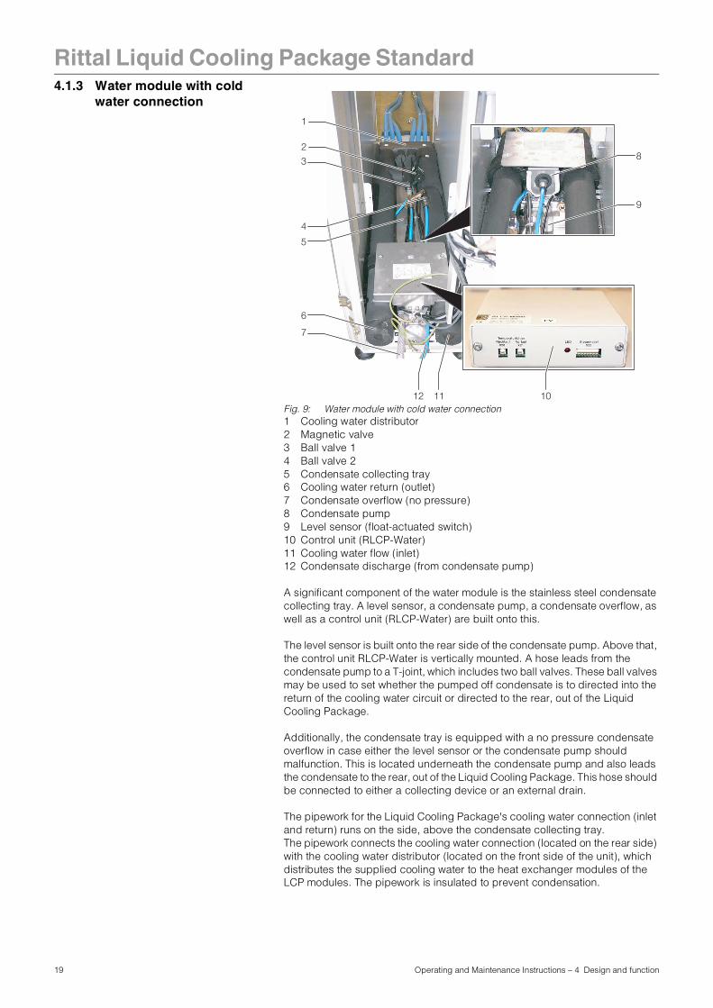
4.1.3 Water module with coldwater connection
Fig. 9: Water module with cold water connection1 Cooling water distributor2 Magnetic valve3 Ball valve 14 Ball valve 25 Condensate collecting tray6 Cooling water return (outlet)7 Condensate overflow (no pressure)8 Condensate pump9 Level sensor (float-actuated switch)10 Control unit (RLCP-Water)11 Cooling water flow (inlet)12 Condensate discharge (from condensate pump)
A significant component of the water module is the stainless steel condensate collecting tray. A level sensor, a condensate pump, a condensate overflow, as well as a control unit (RLCP-Water) are built onto this.
The level sensor is built onto the rear side of the condensate pump. Above that, the control unit RLCP-Water is vertically mounted. A hose leads from the condensate pump to a T-joint, which includes two ball valves. These ball valves may be used to set whether the pumped off condensate is to directed into the return of the cooling water circuit or directed to the rear, out of the Liquid Cooling Package.
Additionally, the condensate tray is equipped with a no pressure condensate overflow in case either the level sensor or the condensate pump should malfunction. This is located underneath the condensate pump and also leads the condensate to the rear, out of the Liquid Cooling Package. This hose should be connected to either a collecting device or an external drain.
The pipework for the Liquid Cooling Package's cooling water connection (inlet and return) runs on the side, above the condensate collecting tray. The pipework connects the cooling water connection (located on the rear side) with the cooling water distributor (located on the front side of the unit), which distributes the supplied cooling water to the heat exchanger modules of the LCP modules. The pipework is insulated to prevent condensation.
2
1
4
3
5
6
7
8
9
11 1012
19 Operating and Maintenance Instructions – 4 Design and function
Rittal Liquid Cooling Package Standard
The cooling water connection is connected to the main connections of the cooling water return by two 3/4" externally threaded pipes. The connecting pieces of both pipes are composed of T-joints, to allow for the option of connecting from the rear or through the raised floor.The cooling water connection to the cold water network be made by either rigid pipework or flexible hoses, which are available from the Rittal accessory range (Model No. SK 3301.350/3301.351).
Note:
When flexible hoses are used, Liquid Cooling Package's cooling water connection may optionally be made with quick release fasteners. The fasteners are available from the Rittal accessory range (Model No. SK 3301.360).
20 Operating and Maintenance Instructions – 4 Design and function
Rittal Liquid Cooling Package Standard
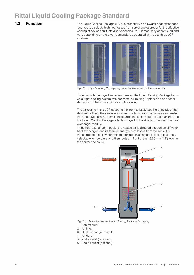
4.2 Function The Liquid Cooling Package (LCP) is essentially an air/water heat exchanger.It serves to dissipate high heat losses from server enclosures or for the effective cooling of devices built into a server enclosure. It is modularly constructed and can, depending on the given demands, be operated with up to three LCP modules.
Fig. 10: Liquid Cooling Package equipped with one, two or three modules
Together with the bayed server enclosures, the Liquid Cooling Package forms an airtight cooling system with horizontal air routing. It places no additional demands on the room's climate control system.
The air routing in the LCP supports the "front to back" cooling principle of the devices built into the server enclosure. The fans draw the warm air exhausted from the devices in the server enclosure in the entire height of the rear area into the Liquid Cooling Package, which is bayed to the side and then into the heat exchanger module. In the heat exchanger module, the heated air is directed through an air/water heat exchanger, and its thermal energy (heat losses from the server) is transferred to a cold water system. Through this, the air is cooled to a freely selectable temperature and then routed in front of the 482.6 mm (19") level in the server enclosure.
Fig. 11: Air routing on the Liquid Cooling Package (top view)1 Fan module2 Air inlet3 Heat exchanger module4 Air outlet5 2nd air inlet (optional)6 2nd air outlet (optional)
3
25
46
1
21 Operating and Maintenance Instructions – 4 Design and function
Rittal Liquid Cooling Package Standard
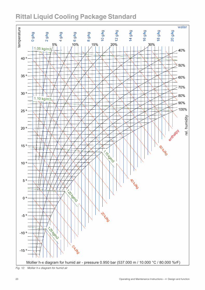
The temperature control of the cold air which is blown in takes place through constant comparison of the actual temperature with the setpoint temperature set on the Liquid Cooling Package's control unit. The temperature of the cold air which is blown in may be set between +20 °C and + 40 °C (in connection with a CMC-TC: +10 °C and + 50 °C/preset +20 °C).If the setpoint temperature is exceeded, the magnetic valve in the cooling water system opens, and the heat exchangers are provided with cold water. Also, the temperature differential between the cold air that is blown in and the warm air that is drawn is used to determine and set the fan speed. The control attempts to maintain a constant temperature through opening and closing the magnetic valve. Only when the actual temperature falls below the value of "setpoint temperature minus hysteresis" is the magnetic valve closed continuously. The hysteresis value is set at 3 K as standard.Any condensate which may develop is collected in each individual LCP module and led to the condensate collecting tray which is integrated into the water module of the Liquid Cooling Package.Upon reaching a defined condensate level in the collecting tray, the level sensor activates the condensate pump. This routes the condensate either to the return of the cooling system or out of the Liquid Cooling Package, as desired. Further, a condensate overflow hose leads from the tray to the exterior, so that, if necessary, (e.g. in the event of a defective level sensor or a defective condensate pump) liquid is led away.
Note:
The water inlet temperature must always be set so that in no case does the temperature fall below the dewpoint (cf. Fig. 12).
22 Operating and Maintenance Instructions – 4 Design and function
Rittal Liquid Cooling Package Standard
Fig. 12: Mollier h-x diagram for humid air
water
tem
pera
ture
rel.
hum
idity
entha
lpy
Mollier h-x diagram for humid air - pressure 0.950 bar (537.000 m / 10.000 °C / 80.000 %rF)
23 Operating and Maintenance Instructions – 4 Design and function
Rittal Liquid Cooling Package Standard
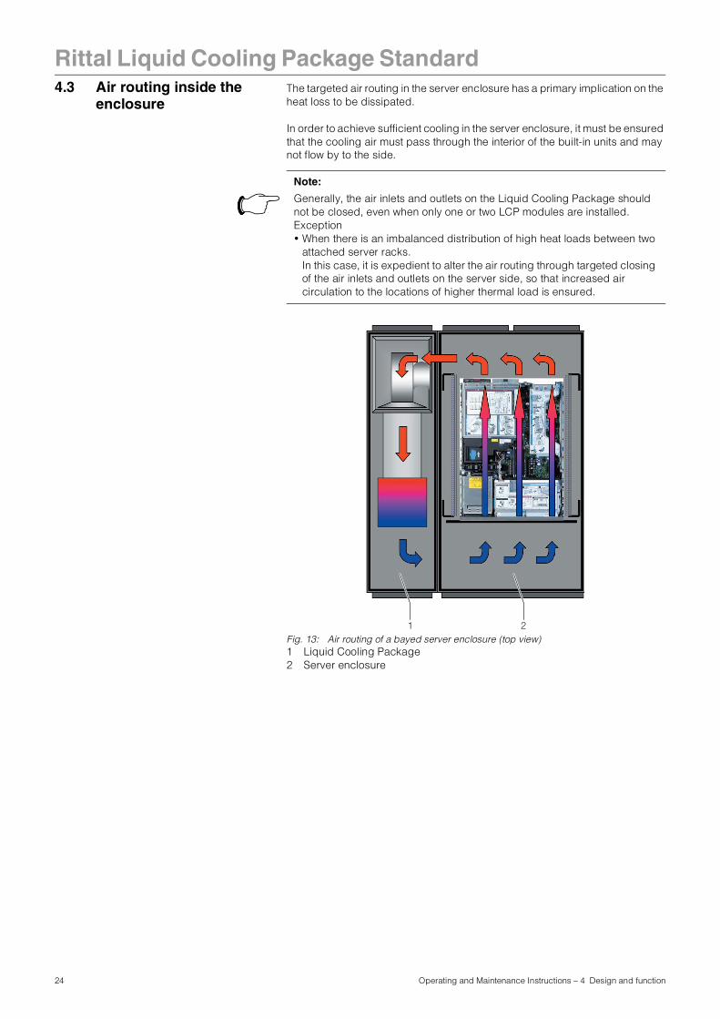
4.3 Air routing inside theenclosure The targeted air routing in the server enclosure has a primary implication on the heat loss to be dissipated.
In order to achieve sufficient cooling in the server enclosure, it must be ensured that the cooling air must pass through the interior of the built-in units and may not flow by to the side.
Fig. 13: Air routing of a bayed server enclosure (top view)1 Liquid Cooling Package2 Server enclosure
Note:
Generally, the air inlets and outlets on the Liquid Cooling Package should not be closed, even when only one or two LCP modules are installed. Exception• When there is an imbalanced distribution of high heat loads between two
attached server racks.In this case, it is expedient to alter the air routing through targeted closing of the air inlets and outlets on the server side, so that increased air circulation to the locations of higher thermal load is ensured.
21
24 Operating and Maintenance Instructions – 4 Design and function
Rittal Liquid Cooling Package Standard
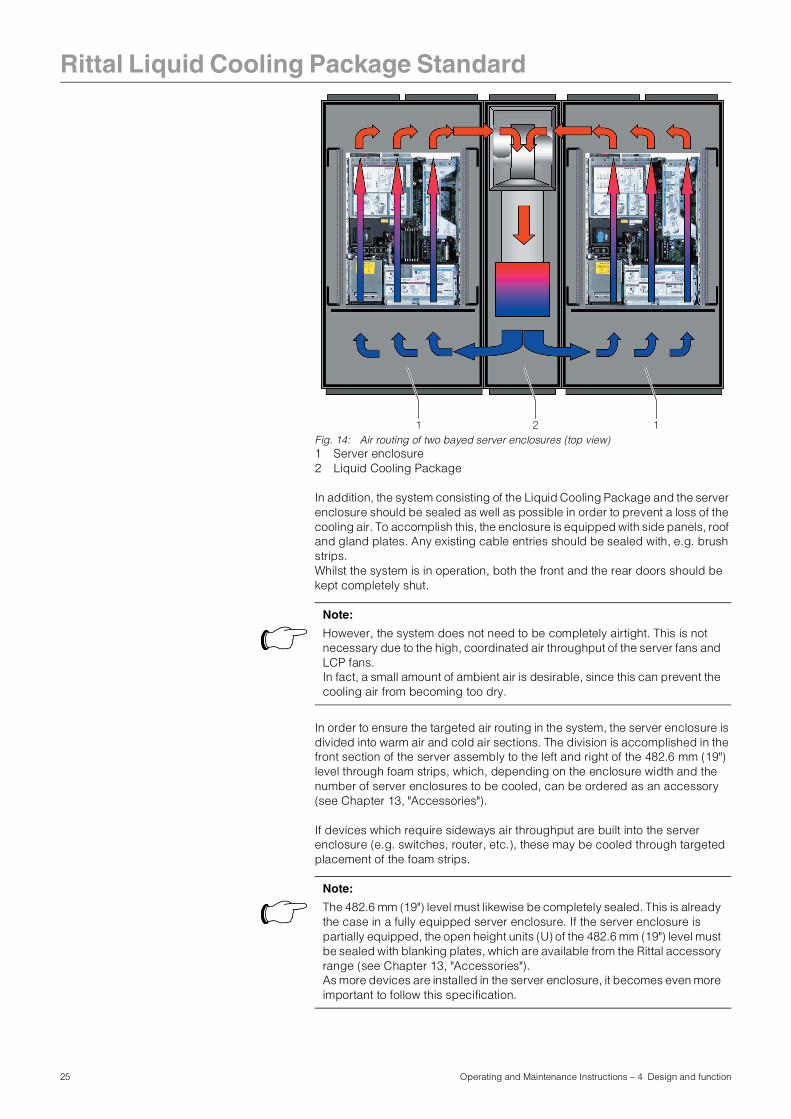
Fig. 14: Air routing of two bayed server enclosures (top view)1 Server enclosure2 Liquid Cooling Package
In addition, the system consisting of the Liquid Cooling Package and the server enclosure should be sealed as well as possible in order to prevent a loss of the cooling air. To accomplish this, the enclosure is equipped with side panels, roof and gland plates. Any existing cable entries should be sealed with, e.g. brush strips. Whilst the system is in operation, both the front and the rear doors should be kept completely shut.
In order to ensure the targeted air routing in the system, the server enclosure is divided into warm air and cold air sections. The division is accomplished in the front section of the server assembly to the left and right of the 482.6 mm (19") level through foam strips, which, depending on the enclosure width and the number of server enclosures to be cooled, can be ordered as an accessory (see Chapter 13, "Accessories").
If devices which require sideways air throughput are built into the server enclosure (e.g. switches, router, etc.), these may be cooled through targeted placement of the foam strips.
21 1
Note:
However, the system does not need to be completely airtight. This is not necessary due to the high, coordinated air throughput of the server fans and LCP fans. In fact, a small amount of ambient air is desirable, since this can prevent the cooling air from becoming too dry.
Note:
The 482.6 mm (19") level must likewise be completely sealed. This is already the case in a fully equipped server enclosure. If the server enclosure is partially equipped, the open height units (U) of the 482.6 mm (19") level must be sealed with blanking plates, which are available from the Rittal accessory range (see Chapter 13, "Accessories").As more devices are installed in the server enclosure, it becomes even more important to follow this specification.
25 Operating and Maintenance Instructions – 4 Design and function
Rittal Liquid Cooling Package Standard
4.4 Possible moduleconfigurationsThe Liquid Cooling Package may be operated with one, two, or three LCP modules and may be used to cool one or two server enclosures.In this regard, a modification or expansion of the module or system configurations has no effect upon the cold water and power connection, or a possible connection with a Rittal CMC-TC.
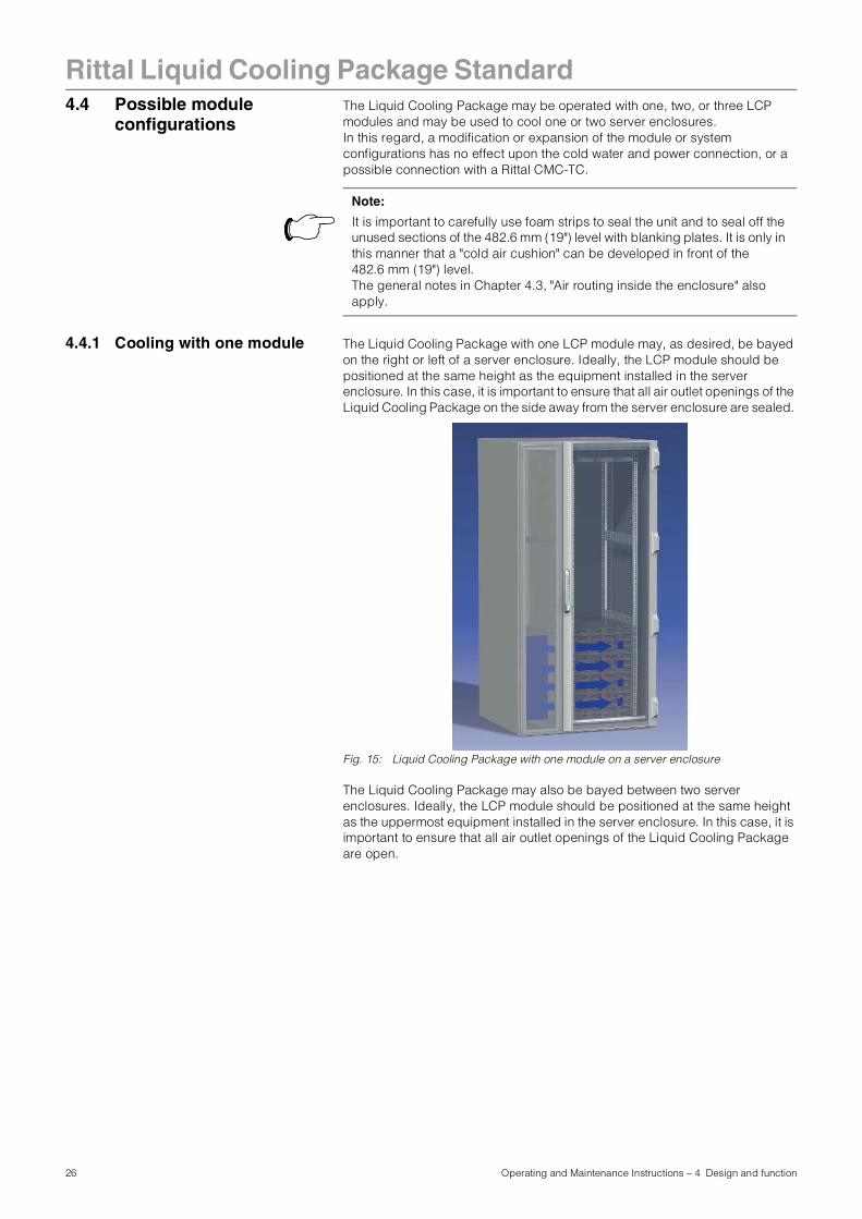
4.4.1 Cooling with one module The Liquid Cooling Package with one LCP module may, as desired, be bayed on the right or left of a server enclosure. Ideally, the LCP module should be positioned at the same height as the equipment installed in the server enclosure. In this case, it is important to ensure that all air outlet openings of the Liquid Cooling Package on the side away from the server enclosure are sealed.
Fig. 15: Liquid Cooling Package with one module on a server enclosure
The Liquid Cooling Package may also be bayed between two server enclosures. Ideally, the LCP module should be positioned at the same height as the uppermost equipment installed in the server enclosure. In this case, it is important to ensure that all air outlet openings of the Liquid Cooling Package are open.
Note:
It is important to carefully use foam strips to seal the unit and to seal off the unused sections of the 482.6 mm (19") level with blanking plates. It is only in this manner that a "cold air cushion" can be developed in front of the 482.6 mm (19") level.The general notes in Chapter 4.3, "Air routing inside the enclosure" also apply.
26 Operating and Maintenance Instructions – 4 Design and function
Rittal Liquid Cooling Package Standard
Fig. 16: Liquid Cooling Package with one module between two server enclosures
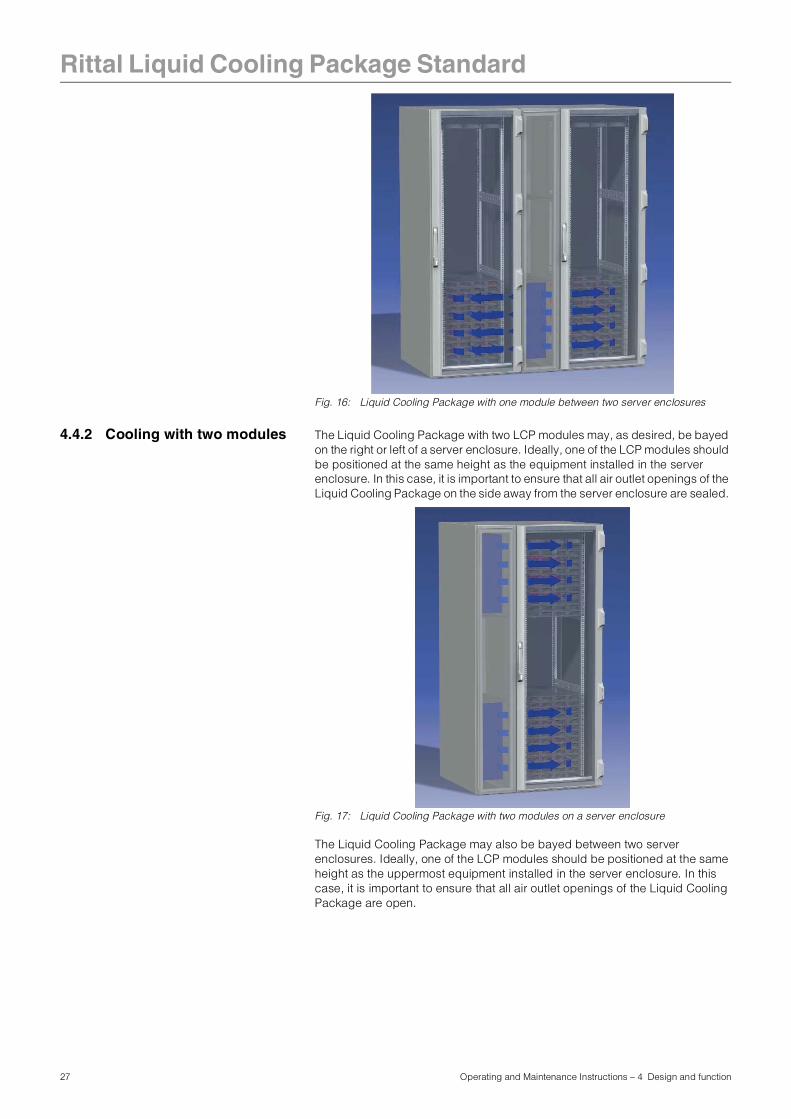
4.4.2 Cooling with two modules The Liquid Cooling Package with two LCP modules may, as desired, be bayed on the right or left of a server enclosure. Ideally, one of the LCP modules should be positioned at the same height as the equipment installed in the server enclosure. In this case, it is important to ensure that all air outlet openings of the Liquid Cooling Package on the side away from the server enclosure are sealed.
Fig. 17: Liquid Cooling Package with two modules on a server enclosure
The Liquid Cooling Package may also be bayed between two server enclosures. Ideally, one of the LCP modules should be positioned at the same height as the uppermost equipment installed in the server enclosure. In this case, it is important to ensure that all air outlet openings of the Liquid Cooling Package are open.
27 Operating and Maintenance Instructions – 4 Design and function
Rittal Liquid Cooling Package Standard
Fig. 18: Liquid Cooling Package with two modules between two server enclosures
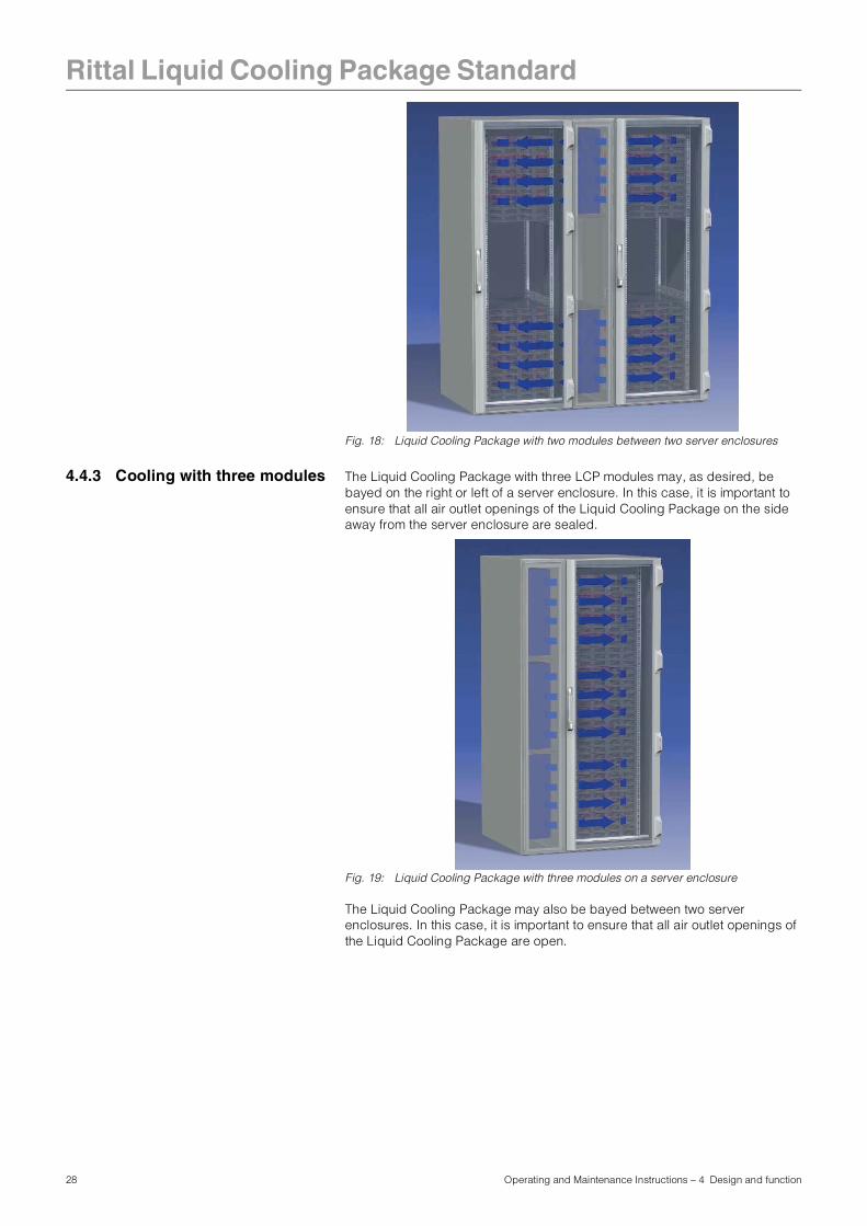
4.4.3 Cooling with three modules The Liquid Cooling Package with three LCP modules may, as desired, be bayed on the right or left of a server enclosure. In this case, it is important to ensure that all air outlet openings of the Liquid Cooling Package on the side away from the server enclosure are sealed.
Fig. 19: Liquid Cooling Package with three modules on a server enclosure
The Liquid Cooling Package may also be bayed between two server enclosures. In this case, it is important to ensure that all air outlet openings of the Liquid Cooling Package are open.
28 Operating and Maintenance Instructions – 4 Design and function
Rittal Liquid Cooling Package Standard
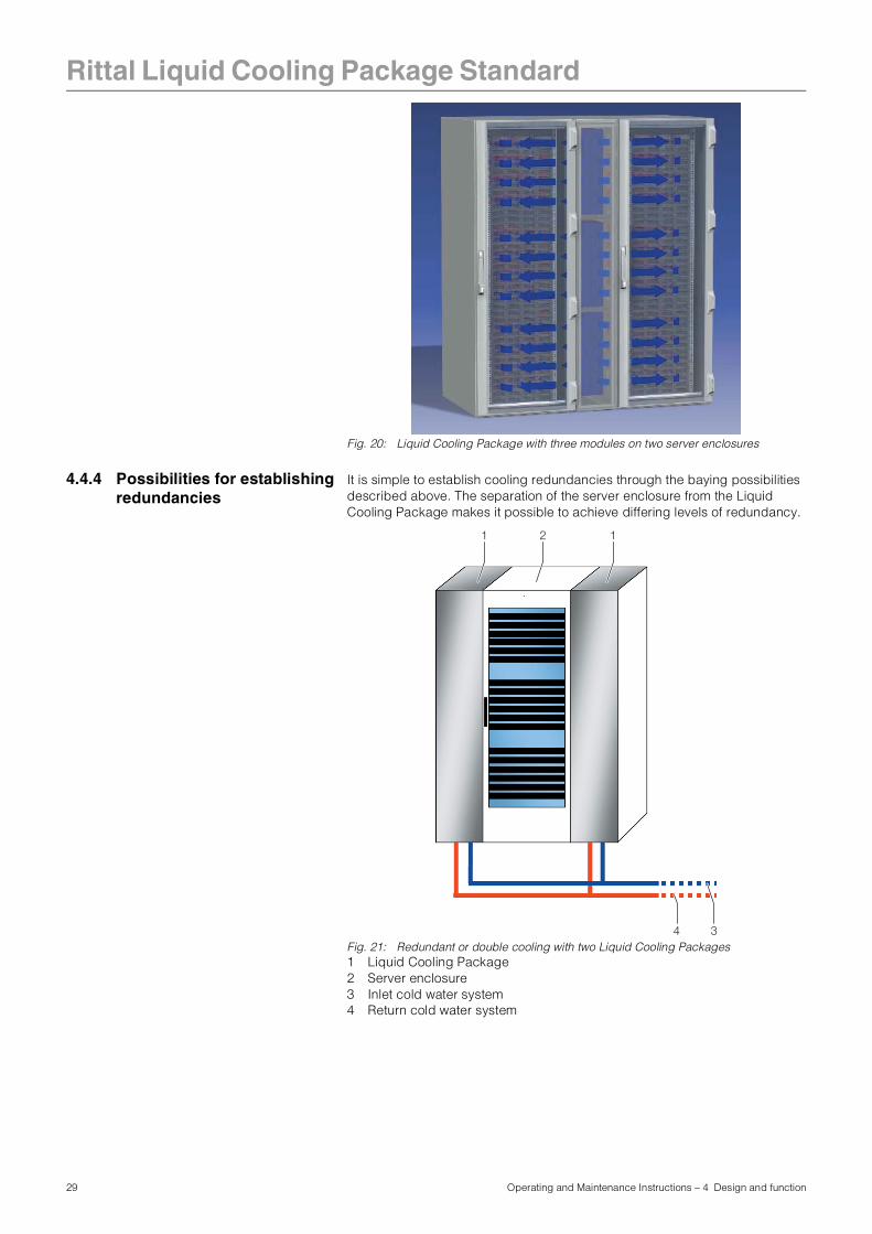
Fig. 20: Liquid Cooling Package with three modules on two server enclosures
4.4.4 Possibilities for establishing redundancies
It is simple to establish cooling redundancies through the baying possibilities described above. The separation of the server enclosure from the Liquid Cooling Package makes it possible to achieve differing levels of redundancy.
Fig. 21: Redundant or double cooling with two Liquid Cooling Packages1 Liquid Cooling Package2 Server enclosure3 Inlet cold water system4 Return cold water system
34
21 1
29 Operating and Maintenance Instructions – 4 Design and function
Rittal Liquid Cooling Package Standard
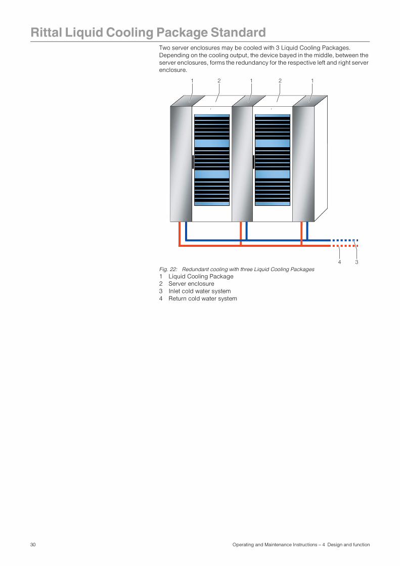
Two server enclosures may be cooled with 3 Liquid Cooling Packages. Depending on the cooling output, the device bayed in the middle, between the server enclosures, forms the redundancy for the respective left and right server enclosure.Fig. 22: Redundant cooling with three Liquid Cooling Packages1 Liquid Cooling Package2 Server enclosure3 Inlet cold water system4 Return cold water system
34
21 21 1
30 Operating and Maintenance Instructions – 4 Design and function
Rittal Liquid Cooling Package Standard
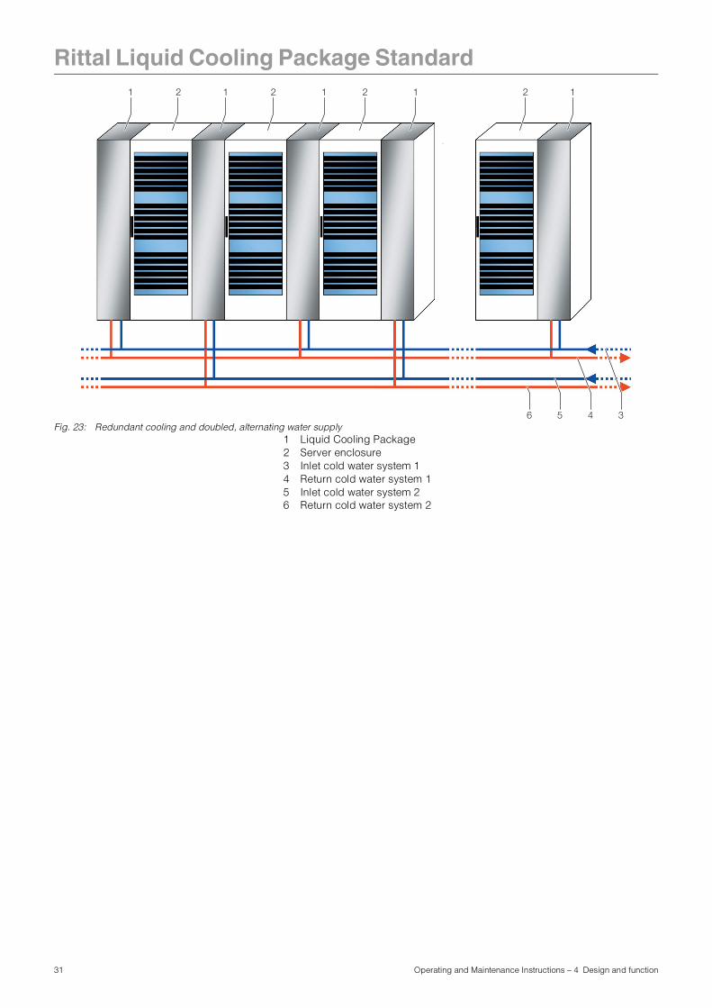
Fig. 23: Redundant cooling and doubled, alternating water supply1 Liquid Cooling Package2 Server enclosure3 Inlet cold water system 14 Return cold water system 15 Inlet cold water system 26 Return cold water system 2
56 34
21 21 1 2 1 2 1
31 Operating and Maintenance Instructions – 4 Design and function
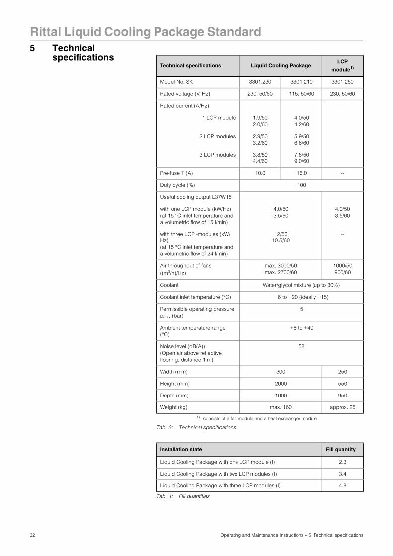
32 Operating and Maintenance Instructions – 5 Technical specifications
Rittal Liquid Cooling Package Standard5 Technical
specifications
Tab. 3: Technical specifications
Tab. 4: Fill quantities
Technical specifications Liquid Cooling PackageLCP
module1)
1) consists of a fan module and a heat exchanger module
Model No. SK 3301.230 3301.210 3301.250
Rated voltage (V, Hz) 230, 50/60 115, 50/60 230, 50/60
Rated current (A/Hz) --
1 LCP module 1.9/502.0/60
4.0/504.2/60
2 LCP modules 2.9/503.2/60
5.9/506.6/60
3 LCP modules 3.8/504.4/60
7.8/509.0/60
Pre-fuse T (A) 10.0 16.0 --
Duty cycle (%) 100
Useful cooling output L37W15
with one LCP module (kW/Hz) (at 15 °C inlet temperature and a volumetric flow of 15 l/min)
4.0/503.5/60
4.0/503.5/60
with three LCP -modules (kW/Hz)(at 15 °C inlet temperature and a volumetric flow of 24 l/min)
12/5010.5/60
--
Air throughput of fans ((m3/h)/Hz)
max. 3000/50max. 2700/60
1000/50900/60
Coolant Water/glycol mixture (up to 30%)
Coolant inlet temperature (°C) +6 to +20 (ideally +15)
Permissible operating pressure pmax (bar)
5
Ambient temperature range (°C)
+6 to +40
Noise level (dB(A))(Open air above reflective flooring, distance 1 m)
58
Width (mm) 300 250
Height (mm) 2000 550
Depth (mm) 1000 950
Weight (kg) max. 160 approx. 25
Installation state Fill quantity
Liquid Cooling Package with one LCP module (l) 2.3
Liquid Cooling Package with two LCP modules (l) 3.4
Liquid Cooling Package with three LCP modules (l) 4.8
33 Operating and Maintenance Instructions – 6 Installation – "Getting Started"
Rittal Liquid Cooling Package Standard6 Installation – "Getting
Started"
6.1 Installation conditions In order to ensure problem-free operation of the Liquid Cooling Package, the following conditions for the installation location should be observed:
Supply connections required at the installation site
Tab. 5: Supply connections required at the installation site
Floor conditions- The floor of the installation space should be rigid and level.
- Choose the installation site so that the unit is not situated on a step, unlevel location, etc.
Climatic conditions- The room temperature must be between +6 °C and +40 °C
- The relative air humidity must be below 80%.
Electromagnetic interference- Interfering electrical installations (high frequency) should be avoided.
Type of connection Connection description:
Power connection: - 230 V, 50/60 Hz/115 V, 50/60 Hz,
- Shockproof socket,
- IEC socket or
- Fixed wiring
Cooling water connection: - +6 °C to +20 °C inlet temperature
- 5 bar permissible operating pressure
- Volumetric flow: depending on design (cf. Chapter 6.5.1, "Cooling output")
- 3/4" threaded pipe connection
Note:
Please see the notes and data regarding the cold water connection in Chapter 6.4.2, "Cooling water connection" and in Chapter 14.1, "Hydrological information".
Recommendation:
Room temperature + 22 °C at 50% relative air humidity, according to ASHRAE guidelines.
Rittal Liquid Cooling Package Standard
6.2 Assembling the LiquidCooling Package
6.2.1 Preparatory work on the server enclosure
Before the Liquid Cooling Package can be bayed onto the server enclosure, the following work should be carried out.
- Dismantle the side panels,
- Seal the server enclosure and
- Dismantle the server enclosure door.
Dismantle the side panels
Proceed as follows to dismantle the side panels:• Loosen and remove the 8 assembly screws found on each side panel of the
server enclosure.
• Remove all side panel securing elements from the side of the server enclosure onto which the Liquid Cooling Package is to be bayed.
• Dismantle both side panel mountings from the upper mounting rail of the server enclosure. Use an appropriate lever to do this.
• Loosen and remove the screws on both of the side panel mounting brackets (upper and lower) in the middle of the mounting rail.
• Loosen and remove the screws from the 6 side panel holders on the side mounting rails.
Seal the server enclosureIn order to ensure the targeted air routing in the system, the server enclosure is horizontally divided into warm air and cold air sections by sealing the 482.6 mm (19") level.Proceed as follows to seal the 482.6 mm (19") level:• If the server enclosure is only partially configured, seal the open sections of
the 482.6 mm (19") level using blanking plates. Screw these tightly into the server rack from the front side.
• Fasten the broader (Model No. SK 3301.370/3301.320) of the two foam strips from the Liquid Cooling Package accessories from outside onto one of the front supports of the server rack (cf. Fig. 24). Make sure to install this strip on the side of the server enclosure onto which the Liquid Cooling Package is to be bayed.
• Fasten the smaller (Model No. SK 3301.380/3301.390) of the two foam strips from the Liquid Cooling Package accessories from outside onto one of the front supports of the server rack (cf. Fig. 24). Make sure to install this strip on the side of the server enclosure which will again be sealed by a side panel.
Note:
It is only necessary to dismantle the side panels when the Liquid Cooling package is to be bayed onto a previously erected server enclosure. Otherwise, this work is not necessary.
Caution! Risk of injury!
The side panel holders have sharp-edged teeth, which allow for an earthing of the server enclosure's side panel.
Note:
The blanking plates are available in various heights (U) from the Rittal accessory range.
34 Operating and Maintenance Instructions – 6 Installation – "Getting Started"
Rittal Liquid Cooling Package Standard
Fig. 24: Foam strip on a server rack support 1 Foam strip2 Server rack
• If devices which require cooling via sideways air throughput (e.g. switches, router, etc.) are built into the server enclosure, cut-outs must be incorporated into the foam strips.
• To do this, cut out a piece of the foam strip with a sharp knife.
• If several devices which require sideways air throughput are included, cut out several pieces of the foam strip, as is appropriate, so that, ultimately, there is a cut-out in the foam to the left and right in the height of each such device in the server rack.
• If there is any remaining length of the foam strip on the server rack, cut it off at the top edge of the rack.
• On the side of the server enclosure opposite the Liquid Cooling Packing, mount a side panel on the two side panel mountings. Align it with the front and rear side of the enclosure.
• Using the 8 assembly screws, screw the side panel firmly onto the side panel holders and the side panel mounting brackets.
• Seal off any cable entries which may be present with corresponding brush strips or similar.
1
2
Note:
The Liquid Cooling Package can, as desired, be bayed onto a server enclosure with a width of either 600 mm or 800 mm. Thus, the Liquid Cooling Package accessories include a total of four foam strips with differing dimensions.
The foam strips for a 600 mm wide server enclosure may be ordered with the following numbers from the Rittal accessory range:- Model No. SK 3301.370 for the LCP side
- Model No. SK 3301.380 for the side with the side panel
The foam strips for a 800 mm wide server enclosure may be ordered with the following numbers from the Rittal accessory range:- Model No. SK 3301.320 for the LCP side
- Model No. SK 3301.390 for the side with the side panel
35 Operating and Maintenance Instructions – 6 Installation – "Getting Started"
Rittal Liquid Cooling Package Standard
Dismantle the server enclosure doorBefore baying a Liquid Cooling Package, one or both of the server enclosure doors must be dismantled so that the attachment points for the baying connectors are accessible and are not covered by a door edge.Proceed as follows to dismantle a server enclosure door:• Remove the sealing bungs from the four door hinges with an appropriate tool
(e.g. screwdriver).
• Release and open the server enclosure door.
• Loosen the hinge bolts from the four door hinges by raising them with an appropriate tool (e.g. screwdriver). Pull the bolts out of the hinge bolt holding fixture up to the catch (see Fig. 25, Step A).Begin with the lowest door hinge.
Fig. 25: Door hinge – dismantling1 Door hinges2 Hinge bolt holding fixture3 Hinge joint4 Server enclosure door
• Remove the server enclosure door (see Fig. 25, Step B).
Note:
It is only necessary to dismantle a server enclosure door when the Liquid Cooling package is to be bayed onto a previously erected server enclosure. Otherwise, this work is not necessary.If the Liquid Cooling Package is to be set up with a new server enclosure, proceed according to the enclosure's assembly instructions and bay the Liquid Cooling Package onto the server enclosure before assembling the server enclosure doors.
1
1
2
4
3
A
A
B
Note:
Support the server enclosure door so that it will not fall as the door hinges are loosened. If needed, work with a second person.
36 Operating and Maintenance Instructions – 6 Installation – "Getting Started"
Rittal Liquid Cooling Package Standard
6.2.2 Removing the transportclamps• Place the Liquid Cooling Package in the assembly location.
• Remove the 4 screws of the transport clamps on both sides of the Liquid Cooling Package.
Fig. 26: Transport clamps on the Liquid Cooling Package1 Screws on the transport clamps
• Loosen the 8 assembly screws (Fig. 27, Pos. 1) on the rear panel of the Liquid Cooling Package and remove the rear panel.
ACHTUNG !
ATTENTION:
Transportsicherungsschraube vor
Inbetriebnahme entfernen !
Prior to getting started remove screw !
ACHTUNG !
ATTENTION:
Transportsicherungsschraube vor
Inbetriebnahme entfernen !
Prior to getting started remove screw !
1
1
Note:
The screws from the transport clamps must be removed before the Liquid Cooling Package is bayed. Afterwards, they are not accessible.
37 Operating and Maintenance Instructions – 6 Installation – "Getting Started"
Rittal Liquid Cooling Package Standard
6.2.3 Installation and baying of theLiquid Cooling Package
Fig. 27: Liquid Cooling Package (rear)1 Assembly screw
• Position the Liquid Cooling Package on the side of the server enclosure to which it is to be bayed.
• Align the Liquid Cooling Package with the server enclosure using the levelling feet. Be sure that both enclosures are at the same height and are vertically aligned with one another.
• Using assembly screws, fasten three baying connectors each (Fig. 28, Pos. 3) onto the intended attachment points in the mounting rails on the front and rear sides of the Liquid Cooling Package (Fig. 28, Pos. 1).
1
1
1
1
1
1
1
1
Note:
If the Liquid Cooling Package is to be bayed onto the side of a server enclosure which has door hinges or if it is to be bayed between two server enclosures, the door of the LCP must be dismantled before the baying connector is installed so that the attachment points for the baying connector are accessible. Proceed as is described in Chapter 6.2.1, "Preparatory work on the server enclosure".
38 Operating and Maintenance Instructions – 6 Installation – "Getting Started"
Rittal Liquid Cooling Package Standard
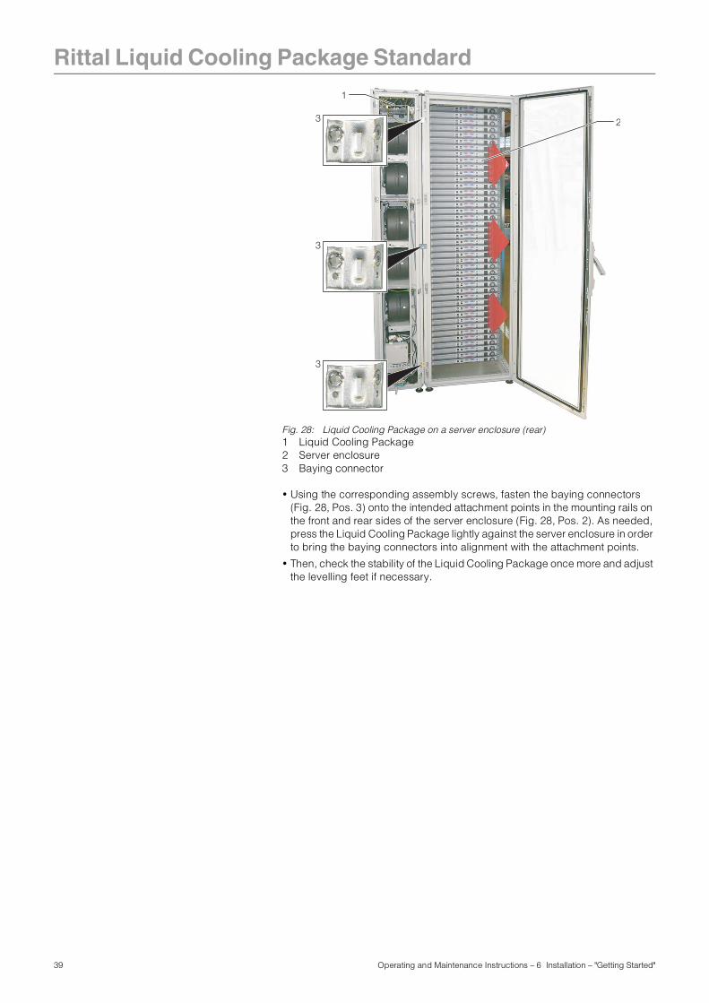
Fig. 28: Liquid Cooling Package on a server enclosure (rear)1 Liquid Cooling Package2 Server enclosure3 Baying connector
• Using the corresponding assembly screws, fasten the baying connectors (Fig. 28, Pos. 3) onto the intended attachment points in the mounting rails on the front and rear sides of the server enclosure (Fig. 28, Pos. 2). As needed, press the Liquid Cooling Package lightly against the server enclosure in order to bring the baying connectors into alignment with the attachment points.
• Then, check the stability of the Liquid Cooling Package once more and adjust the levelling feet if necessary.
1
3
3
3
2
39 Operating and Maintenance Instructions – 6 Installation – "Getting Started"
Rittal Liquid Cooling Package Standard
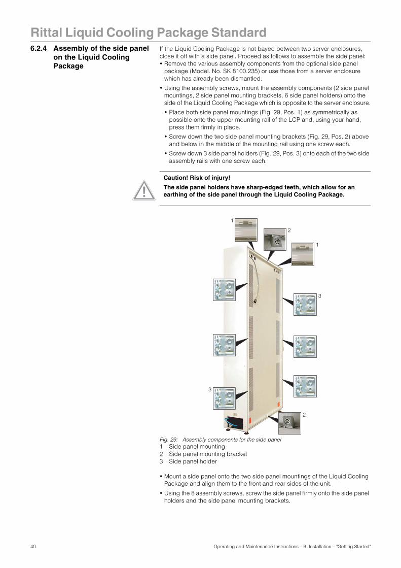
6.2.4 Assembly of the side panelon the Liquid Cooling Package
If the Liquid Cooling Package is not bayed between two server enclosures, close it off with a side panel. Proceed as follows to assemble the side panel: • Remove the various assembly components from the optional side panel
package (Model. No. SK 8100.235) or use those from a server enclosure which has already been dismantled.
• Using the assembly screws, mount the assembly components (2 side panel mountings, 2 side panel mounting brackets, 6 side panel holders) onto the side of the Liquid Cooling Package which is opposite to the server enclosure.
• Place both side panel mountings (Fig. 29, Pos. 1) as symmetrically as possible onto the upper mounting rail of the LCP and, using your hand, press them firmly in place.
• Screw down the two side panel mounting brackets (Fig. 29, Pos. 2) above and below in the middle of the mounting rail using one screw each.
• Screw down 3 side panel holders (Fig. 29, Pos. 3) onto each of the two side assembly rails with one screw each.
Fig. 29: Assembly components for the side panel1 Side panel mounting2 Side panel mounting bracket 3 Side panel holder
• Mount a side panel onto the two side panel mountings of the Liquid Cooling Package and align them to the front and rear sides of the unit.
• Using the 8 assembly screws, screw the side panel firmly onto the side panel holders and the side panel mounting brackets.
Caution! Risk of injury!
The side panel holders have sharp-edged teeth, which allow for an earthing of the side panel through the Liquid Cooling Package.
1
1
2
2
3
3
40 Operating and Maintenance Instructions – 6 Installation – "Getting Started"
Rittal Liquid Cooling Package Standard
6.3 Assembly of an LCPmoduleAs delivered, the Liquid Cooling Package is always configured with only one LCP module in the lower module plug-in.Depending on the configuration of the server enclosure, it may be necessary to relocate the LCP module or retrofit with additional LCP modules.
6.3.1 Removal of an LCP module Proceed as follows to remove an LCP module.• Open the Liquid Cooling Package door.
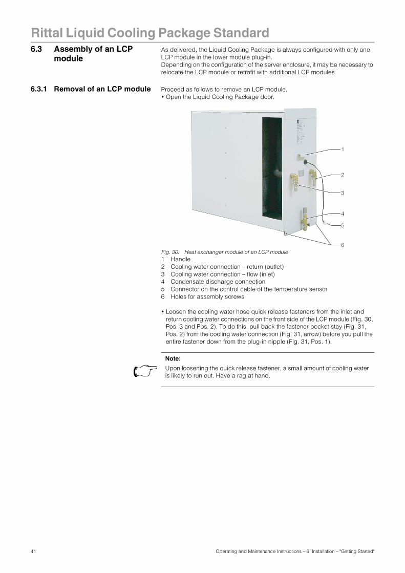
Fig. 30: Heat exchanger module of an LCP module1 Handle2 Cooling water connection – return (outlet)3 Cooling water connection – flow (inlet)4 Condensate discharge connection5 Connector on the control cable of the temperature sensor6 Holes for assembly screws
• Loosen the cooling water hose quick release fasteners from the inlet and return cooling water connections on the front side of the LCP module (Fig. 30, Pos. 3 and Pos. 2). To do this, pull back the fastener pocket stay (Fig. 31, Pos. 2) from the cooling water connection (Fig. 31, arrow) before you pull the entire fastener down from the plug-in nipple (Fig. 31, Pos. 1).
5
6
2
1
3
4
Note:
Upon loosening the quick release fastener, a small amount of cooling water is likely to run out. Have a rag at hand.
41 Operating and Maintenance Instructions – 6 Installation – "Getting Started"
Rittal Liquid Cooling Package Standard
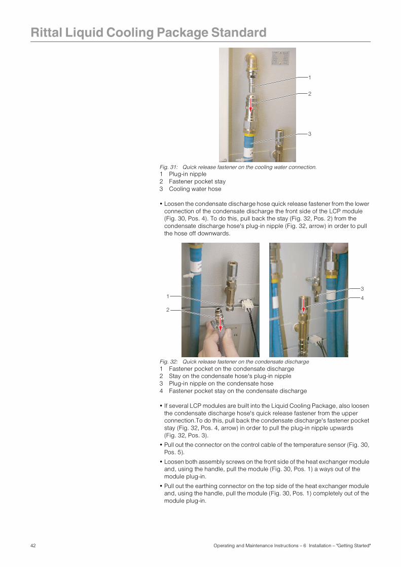
Fig. 31: Quick release fastener on the cooling water connection.1 Plug-in nipple2 Fastener pocket stay3 Cooling water hose
• Loosen the condensate discharge hose quick release fastener from the lower connection of the condensate discharge the front side of the LCP module (Fig. 30, Pos. 4). To do this, pull back the stay (Fig. 32, Pos. 2) from the condensate discharge hose's plug-in nipple (Fig. 32, arrow) in order to pull the hose off downwards.
Fig. 32: Quick release fastener on the condensate discharge1 Fastener pocket on the condensate discharge2 Stay on the condensate hose's plug-in nipple 3 Plug-in nipple on the condensate hose4 Fastener pocket stay on the condensate discharge
• If several LCP modules are built into the Liquid Cooling Package, also loosen the condensate discharge hose's quick release fastener from the upper connection.To do this, pull back the condensate discharge's fastener pocket stay (Fig. 32, Pos. 4, arrow) in order to pull the plug-in nipple upwards (Fig. 32, Pos. 3).
• Pull out the connector on the control cable of the temperature sensor (Fig. 30, Pos. 5).
• Loosen both assembly screws on the front side of the heat exchanger module and, using the handle, pull the module (Fig. 30, Pos. 1) a ways out of the module plug-in.
• Pull out the earthing connector on the top side of the heat exchanger module and, using the handle, pull the module (Fig. 30, Pos. 1) completely out of the module plug-in.
3
2
1
31 4
2
42 Operating and Maintenance Instructions – 6 Installation – "Getting Started"
Rittal Liquid Cooling Package Standard
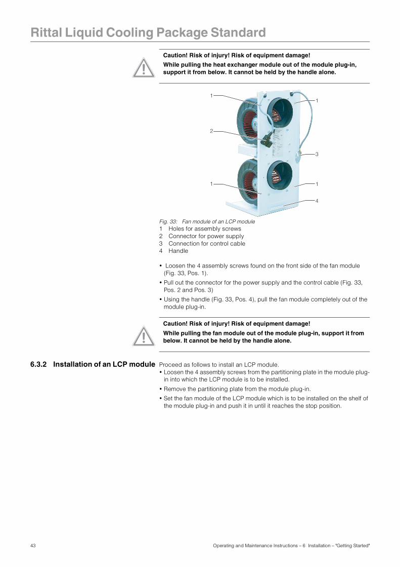
Fig. 33: Fan module of an LCP module1 Holes for assembly screws2 Connector for power supply3 Connection for control cable4 Handle
• Loosen the 4 assembly screws found on the front side of the fan module (Fig. 33, Pos. 1).
• Pull out the connector for the power supply and the control cable (Fig. 33, Pos. 2 and Pos. 3)
• Using the handle (Fig. 33, Pos. 4), pull the fan module completely out of the module plug-in.
6.3.2 Installation of an LCP module Proceed as follows to install an LCP module.• Loosen the 4 assembly screws from the partitioning plate in the module plug-
in into which the LCP module is to be installed.
• Remove the partitioning plate from the module plug-in.
• Set the fan module of the LCP module which is to be installed on the shelf of the module plug-in and push it in until it reaches the stop position.
Caution! Risk of injury! Risk of equipment damage!
While pulling the heat exchanger module out of the module plug-in, support it from below. It cannot be held by the handle alone.
11
1
4
1
2
3
Caution! Risk of injury! Risk of equipment damage!
While pulling the fan module out of the module plug-in, support it from below. It cannot be held by the handle alone.
43 Operating and Maintenance Instructions – 6 Installation – "Getting Started"
Rittal Liquid Cooling Package Standard
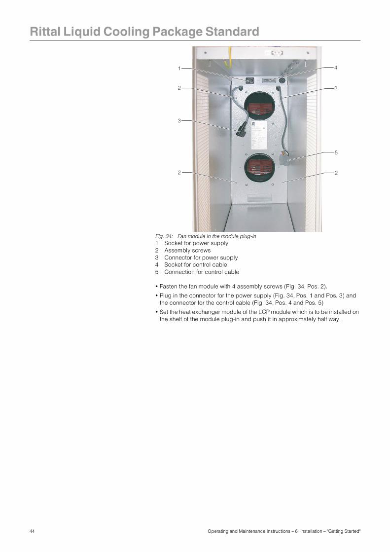
Fig. 34: Fan module in the module plug-in1 Socket for power supply2 Assembly screws3 Connector for power supply4 Socket for control cable5 Connection for control cable
• Fasten the fan module with 4 assembly screws (Fig. 34, Pos. 2).
• Plug in the connector for the power supply (Fig. 34, Pos. 1 and Pos. 3) and the connector for the control cable (Fig. 34, Pos. 4 and Pos. 5)
• Set the heat exchanger module of the LCP module which is to be installed on the shelf of the module plug-in and push it in approximately half way.
4
5
2
2
2
3
2
1
44 Operating and Maintenance Instructions – 6 Installation – "Getting Started"
Rittal Liquid Cooling Package Standard
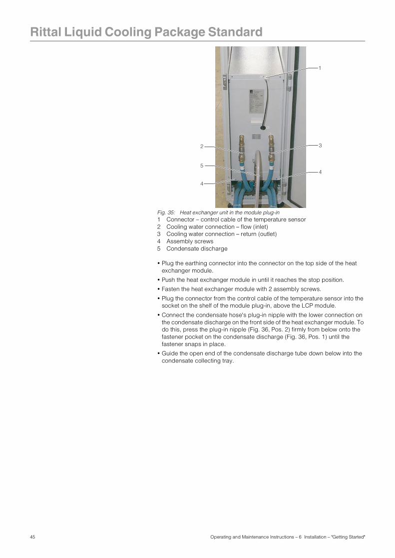
Fig. 35: Heat exchanger unit in the module plug-in1 Connector – control cable of the temperature sensor2 Cooling water connection – flow (inlet)3 Cooling water connection – return (outlet)4 Assembly screws5 Condensate discharge
• Plug the earthing connector into the connector on the top side of the heat exchanger module.
• Push the heat exchanger module in until it reaches the stop position.
• Fasten the heat exchanger module with 2 assembly screws.
• Plug the connector from the control cable of the temperature sensor into the socket on the shelf of the module plug-in, above the LCP module.
• Connect the condensate hose's plug-in nipple with the lower connection on the condensate discharge on the front side of the heat exchanger module. To do this, press the plug-in nipple (Fig. 36, Pos. 2) firmly from below onto the fastener pocket on the condensate discharge (Fig. 36, Pos. 1) until the fastener snaps in place.
• Guide the open end of the condensate discharge tube down below into the condensate collecting tray.
3
5
1
4
2
4
45 Operating and Maintenance Instructions – 6 Installation – "Getting Started"
Rittal Liquid Cooling Package Standard
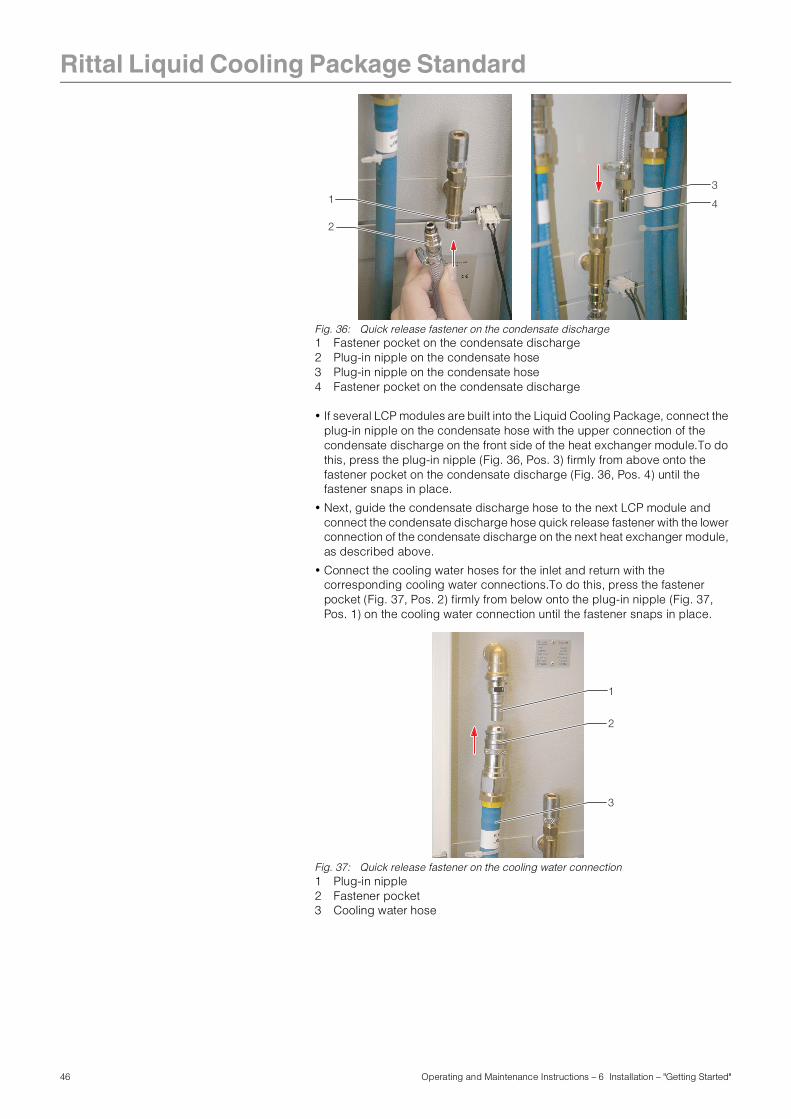
Fig. 36: Quick release fastener on the condensate discharge1 Fastener pocket on the condensate discharge2 Plug-in nipple on the condensate hose3 Plug-in nipple on the condensate hose4 Fastener pocket on the condensate discharge
• If several LCP modules are built into the Liquid Cooling Package, connect the plug-in nipple on the condensate hose with the upper connection of the condensate discharge on the front side of the heat exchanger module.To do this, press the plug-in nipple (Fig. 36, Pos. 3) firmly from above onto the fastener pocket on the condensate discharge (Fig. 36, Pos. 4) until the fastener snaps in place.
• Next, guide the condensate discharge hose to the next LCP module and connect the condensate discharge hose quick release fastener with the lower connection of the condensate discharge on the next heat exchanger module, as described above.
• Connect the cooling water hoses for the inlet and return with the corresponding cooling water connections.To do this, press the fastener pocket (Fig. 37, Pos. 2) firmly from below onto the plug-in nipple (Fig. 37, Pos. 1) on the cooling water connection until the fastener snaps in place.
Fig. 37: Quick release fastener on the cooling water connection1 Plug-in nipple2 Fastener pocket3 Cooling water hose
31 4
2
3
2
1
46 Operating and Maintenance Instructions – 6 Installation – "Getting Started"
Rittal Liquid Cooling Package Standard
6.4 Connecting theLiquid Cooling Package
6.4.1 Electrical connection
The Liquid Cooling Package's power supply is made either through the power supply in the server enclosure or through a separate infeed, as desired. The unit is always delivered with a connecting cable without a mains plug so that the user may connect his/her own plug (earthing plug, IEC connector, etc.) according to local requirements.
Note:
Please keep this electrical documentation readily available so that it is always on hand when needed. This is the only documentation which is authoritative for the unit.
Caution!
Work on electrical systems or equipment may only be carried out by an electrician or by trained personnel guided and supervised by an electrician. All work must be carried out in accordance with electrical engineering regulations.
The unit may only be connected after the above-named personnel have read this information.
Use insulated tools.
The connection regulations of the appropriate power company are to be followed.
The voltage values shown in the wiring plan or on the rating plate must match the mains voltage.
The pre-fuse specified in the wiring plan or on the rating plate should be provided as power protection. The unit must be individually fused.
The unit must be connected to the mains via an isolating device which ensures at least 3 mm contact opening when switched off.
The mains connection may only be made using the connection cable which extends from the unit.
No additional control equipment may be connected upstream of the device at the supply end.
Note:
The cross section and the fusing of the connection cable may be found in Chapter 14.4, "Circuit diagram".
47 Operating and Maintenance Instructions – 6 Installation – "Getting Started"
Rittal Liquid Cooling Package Standard
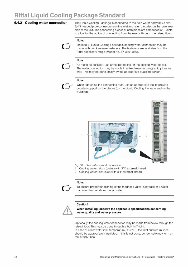
6.4.2 Cooling water connection The Liquid Cooling Package is connected to the cold water network via two3/4" threaded pipe connections on the inlet and return, located on the lower rear side of the unit. The connecting pieces of both pipes are composed of T-joints, to allow for the option of connecting from the rear or through the raised floor.
Fig. 38: Cold water network connection:1 Cooling water return (outlet) with 3/4" external thread2 Cooling water flow (inlet) with 3/4" external thread
Optionally, the cooling water connection may be made from below through the raised floor. This may be done through a built-in T-joint.In case of a low water inlet temperature (<12 °C), the inlet and return lines should be appropriately insulated. If this is not done, condensate may form on the supply lines.
Note:
Optionally, Liquid Cooling Package's cooling water connection may be made with quick release fasteners. The fasteners are available from the Rittal accessory range (Model No. SK 3301.360).
Note:
As much as possible, use armoured hoses for the cooling water hoses.The water connection may be made in a fixed manner using solid pipes as well. This may be done locally by the appropriate qualified person.
Note:
When tightening the connecting nuts, use an appropriate tool to provide counter-support on the pieces (on the Liquid Cooling Package and on the building).
1 2
Note:
To ensure proper functioning of the magnetic valve, a bypass or a water hammer damper should be provided.
Caution!
When installing, observe the applicable specifications concerning water quality and water pressure.
48 Operating and Maintenance Instructions – 6 Installation – "Getting Started"
Rittal Liquid Cooling Package Standard
Notes on water qualityFor safe operation, it is vital that the VBG guidelines on cooling water are observed (VGB R 455P). Cooling water must not contain any limescale deposits or loose debris and it should have a low level of hardness, particularly a low level of carbonate hardness. For recooling within the plant, the carbonate hardness should not be too high. On the other hand, however, the water should not be so soft that it attacks the operating materials. When recooling the cooling water, the salt content should not rise too high as the result of evaporation of large quantities of water, since electrical conductivity increases as the concentration of dissolved substances rises, and the water thereby becomes more corrosive. For this reason, it is not only always necessary to add a corresponding quantity of fresh water, but also to remove part of the enriched water. Gypsiferous water is unsuitable for cooling purposes because it has a tendency to form boiler scale, which is particularly difficult to remove. Furthermore, cooling water should be free from iron and manganese, because otherwise deposits may occur which settle in the pipes and block them. At best, organic substances should only be present in small quantities, because otherwise sludge deposits and microbiological contamination may occur.
Note:
It is possible to test the flow of the water cycle immediately after connection, since the magnetic valve is open at zero current. That may be done using a CMC (see Chapter 6.7, "Extended options by connecting a Computer Multi Control – Top Concept (CMC-TC)").
Note:
The building-side piping should be designed according to the Tichelmann Principle in order to maintain a hydraulically balanced system. If this is not the case, the flow volume of each Liquid Cooling Package must be assured by using a flow quantity regulator.
Ideally, the Liquid Cooling Package is connected to the cooling water system using a water/water heat exchanger.Advantage:• Reduction of water volumes in the secondary circuit,
• Setting of a defined water quality,
• Setting of a defined input temperature and
• Setting of a defined volumetric flow.
Note:
To avoid frost and corrosion damage as well as biological contaminants, Rittal GmbH & Co. recommends that a water/glycol mixture be used (up to max. 30% glycol).
49 Operating and Maintenance Instructions – 6 Installation – "Getting Started"
Rittal Liquid Cooling Package Standard
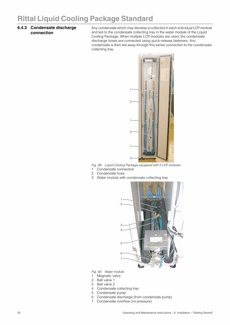
6.4.3 Condensate dischargeconnectionAny condensate which may develop is collected in each individual LCP module and led to the condensate collecting tray in the water module of the Liquid Cooling Package. When multiple LCP modules are used, the condensate discharge hoses are connected using quick-release fasteners. Any condensate is then led away through this series connection to the condensate collecting tray.
Fig. 39: Liquid Cooling Package equipped with 3 LCP modules1 Condensate connection2 Condensate hose3 Water module with condensate collecting tray
Fig. 40: Water module1 Magnetic valve2 Ball valve 13 Ball valve 24 Condensate collecting tray5 Condensate pump6 Condensate discharge (from condensate pump)7 Condensate overflow (no pressure)
1
2
1
2
1
3
1
3
2
4
5
7
6
50 Operating and Maintenance Instructions – 6 Installation – "Getting Started"
Rittal Liquid Cooling Package Standard
Upon reaching a defined condensate level in the collecting tray, a float actuated switch activates a pump, which pumps off the condensate.Basically, there are two options for disposing of the condensate.- Discharge into the cooling water return
- Leading out of the Liquid Cooling Package and disposal through an external drain (factory setting).
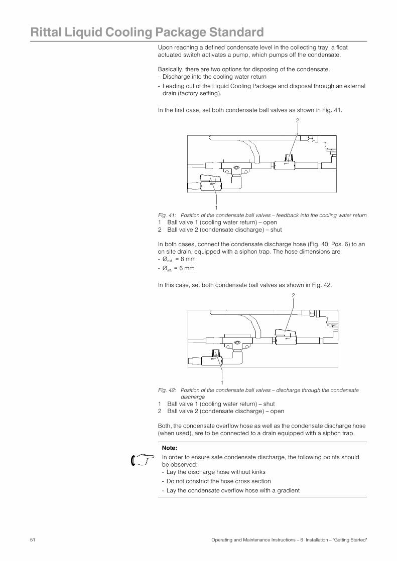
In the first case, set both condensate ball valves as shown in Fig. 41.
Fig. 41: Position of the condensate ball valves – feedback into the cooling water return1 Ball valve 1 (cooling water return) – open2 Ball valve 2 (condensate discharge) – shut
In both cases, connect the condensate discharge hose (Fig. 40, Pos. 6) to an on site drain, equipped with a siphon trap. The hose dimensions are:- Øext. = 8 mm
- Øint. = 6 mm
In this case, set both condensate ball valves as shown in Fig. 42.
Fig. 42: Position of the condensate ball valves – discharge through the condensate discharge
1 Ball valve 1 (cooling water return) – shut2 Ball valve 2 (condensate discharge) – open
Both, the condensate overflow hose as well as the condensate discharge hose (when used), are to be connected to a drain equipped with a siphon trap.
2
1
2
1
Note:
In order to ensure safe condensate discharge, the following points should be observed:- Lay the discharge hose without kinks
- Do not constrict the hose cross section
- Lay the condensate overflow hose with a gradient
51 Operating and Maintenance Instructions – 6 Installation – "Getting Started"
Rittal Liquid Cooling Package Standard
Note:
In order to avoid increased condensation and to reduce energy use, the cooling water temperature should be adapted to match the required cooling output.
52 Operating and Maintenance Instructions – 6 Installation – "Getting Started"
Rittal Liquid Cooling Package Standard
6.5 Cooling operation andcontrol behaviourIf the LCP is provided with power, the magnetic valve controls the cooling water flow according to the established setpoint temperature. For more detailed explanations, please refer to Chapter 4.2, "Function".
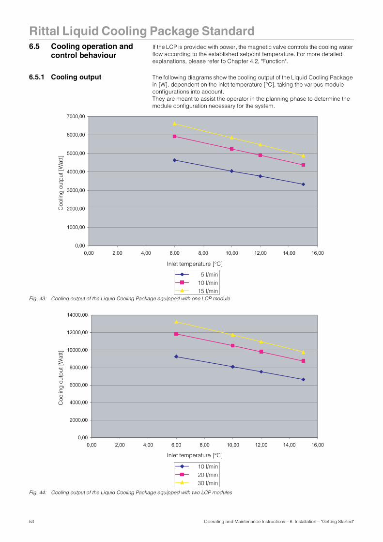
6.5.1 Cooling output The following diagrams show the cooling output of the Liquid Cooling Package in [W], dependent on the inlet temperature [°C], taking the various module configurations into account. They are meant to assist the operator in the planning phase to determine the module configuration necessary for the system.
Fig. 43: Cooling output of the Liquid Cooling Package equipped with one LCP module
Fig. 44: Cooling output of the Liquid Cooling Package equipped with two LCP modules
0,00
1000,00
2000,00
3000,00
4000,00
5000,00
6000,00
7000,00
0,00 2,00 4,00 6,00 8,00 10,00 12,00 14,00 16,00
5 l/min10 l/min15 l/min
Inlet temperature [°C]
Coo
ling
out
put
[Wat
t]
0,00
2000,00
4000,00
6000,00
8000,00
10000,00
12000,00
14000,00
0,00 2,00 4,00 6,00 8,00 10,00 12,00 14,00 16,00
10 l/min20 l/min30 l/min
Inlet temperature [°C]
Coo
ling
out
put
[Wat
t]
53 Operating and Maintenance Instructions – 6 Installation – "Getting Started"
Rittal Liquid Cooling Package Standard
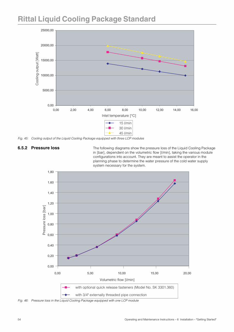
Fig. 45: Cooling output of the Liquid Cooling Package equipped with three LCP modules
6.5.2 Pressure loss The following diagrams show the pressure loss of the Liquid Cooling Package in [bar], dependent on the volumetric flow [l/min], taking the various module configurations into account. They are meant to assist the operator in the planning phase to determine the water pressure of the cold water supply system necessary for the system.
Fig. 46: Pressure loss in the Liquid Cooling Package equipped with one LCP module
0,00
5000,00
10000,00
15000,00
20000,00
25000,00
0,00 2,00 4,00 6,00 8,00 10,00 12,00 14,00 16,00
15 l/min30 l/min45 l/min
Inlet temperature [°C]
Coo
ling
out
put
[W
att]
0,00
0,20
0,40
0,60
0,80
1,00
1,20
1,40
1,60
1,80
0,00 5,00 10,00 15,00 20,00
with 3/4" externally threaded pipe connection
with optional quick release fasteners (Model No. SK 3301.360)
Volumetric flow [l/min]
Pres
sure
loss
[b
ar]
54 Operating and Maintenance Instructions – 6 Installation – "Getting Started"
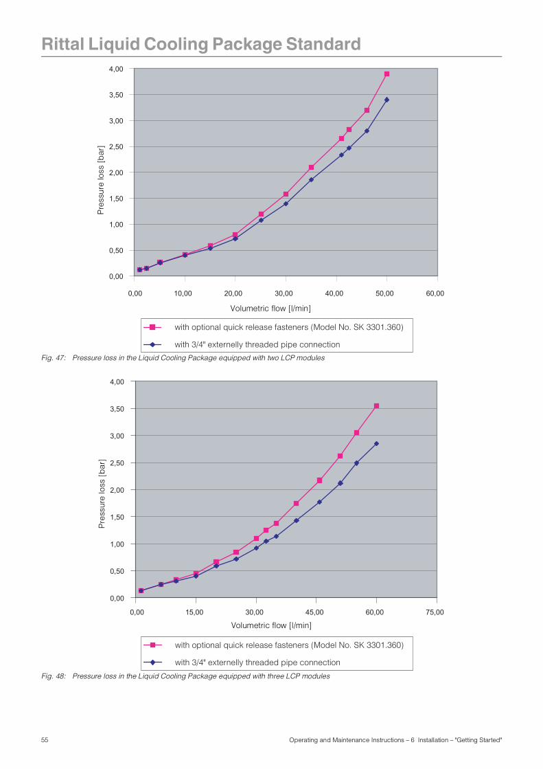
Rittal Liquid Cooling Package Standard
Fig. 47: Pressure loss in the Liquid Cooling Package equipped with two LCP modules
Fig. 48: Pressure loss in the Liquid Cooling Package equipped with three LCP modules
0,00
0,50
1,00
1,50
2,00
2,50
3,00
3,50
4,00
0,00 10,00 20,00 30,00 40,00 50,00 60,00
with 3/4" externelly threaded pipe connection
with optional quick release fasteners (Model No. SK 3301.360)
Volumetric flow [l/min]
Pre
ssur
e lo
ss [
bar
]
0,00
0,50
1,00
1,50
2,00
2,50
3,00
3,50
4,00
0,00 15,00 30,00 45,00 60,00 75,00
with 3/4" externelly threaded pipe connection
with optional quick release fasteners (Model No. SK 3301.360)
Volumetric flow [l/min]
Pre
ssur
e lo
ss [
bar
]
55 Operating and Maintenance Instructions – 6 Installation – "Getting Started"
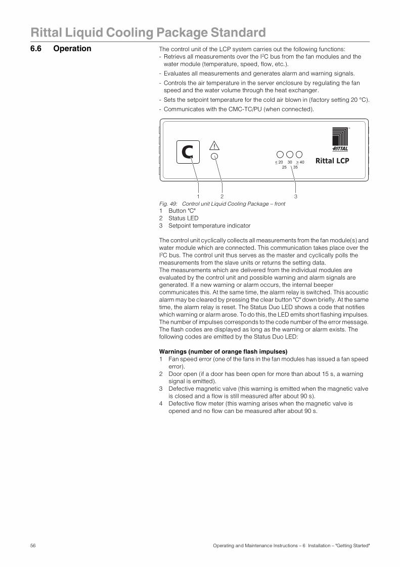
Rittal Liquid Cooling Package Standard
6.6 Operation The control unit of the LCP system carries out the following functions:- Retrievs all measurements over the I2C bus from the fan modules and the water module (temperature, speed, flow, etc.).
- Evaluates all measurements and generates alarm and warning signals.
- Controls the air temperature in the server enclosure by regulating the fan speed and the water volume through the heat exchanger.
- Sets the setpoint temperature for the cold air blown in (factory setting 20 °C).
- Communicates with the CMC-TC/PU (when connected).
Fig. 49: Control unit Liquid Cooling Package – front1 Button "C"2 Status LED3 Setpoint temperature indicator
The control unit cyclically collects all measurements from the fan module(s) and water module which are connected. This communication takes place over the I2C bus. The control unit thus serves as the master and cyclically polls the measurements from the slave units or returns the setting data.The measurements which are delivered from the individual modules are evaluated by the control unit and possible warning and alarm signals are generated. If a new warning or alarm occurs, the internal beeper communicates this. At the same time, the alarm relay is switched. This acoustic alarm may be cleared by pressing the clear button "C" down briefly. At the same time, the alarm relay is reset. The Status Duo LED shows a code that notifies which warning or alarm arose. To do this, the LED emits short flashing impulses. The number of impulses corresponds to the code number of the error message. The flash codes are displayed as long as the warning or alarm exists. The following codes are emitted by the Status Duo LED:
Warnings (number of orange flash impulses)1 Fan speed error (one of the fans in the fan modules has issued a fan speed
error).2 Door open (if a door has been open for more than about 15 s, a warning
signal is emitted).3 Defective magnetic valve (this warning is emitted when the magnetic valve
is closed and a flow is still measured after about 90 s).4 Defective flow meter (this warning arises when the magnetic valve is
opened and no flow can be measured after about 90 s.
Rittal LCP< 20 > 4035
3025
!C
1 2 3
56 Operating and Maintenance Instructions – 6 Installation – "Getting Started"
Rittal Liquid Cooling Package Standard
Alarms (number of red flash impulses)1 Leakage determined (when a leak is detected, the magnetic valve shutsand the fans are turned off for about 30 s. After an additional 30 s, the fans are turned on to maximum speed).
2 Timax exceeded (if the setpoint temperature is exceeded by a given value (standard 5 K), this high temperature alarm is triggered).
3 No water module (this alarm is triggered when no water module is found).4 No fan module (this alarm is triggered when no fan module is found).5 Temperature sensor faulty (this alarm is triggered when a temperature
sensor (water or air temperature) is faulty).
If no warning or alarm exists, the status LED shows green.
Changing the Module ConfigurationsIf a new module is found over the I2C bus or when a module which had previously been found is no longer present, a "Configuration change" message will be triggered. This will also be shared acoustically and via the alarm relay. This will be indicated on the status LED through quick flashes in the series "red/orange/green". This message is cleared by pressing the Clear button "C" for approx. 2 s, and the new configuration is stored in the internal memory of the control unit.
Design of the temperature control circuitThe actual temperature values of the cold air on the air input side delivered by the LCP modules are used to control the air which is blown into the server enclosure. An average value is determined from the actual temperature values. The control unit constantly compares this (average) actual temperature with the set setpoint temperature. When the setpoint temperature is exceeded, the control unit attempts to maintain a constant temperature by opening and closing the magnetic valve (at approx. 1 minute intervals). Only when the actual temperature falls below the value of "setpoint temperature minus hysteresis" is the magnetic valve closed continuously, i.e. no cold water flows through the heat exchanger. The hysteresis value is normally set at 3 K. Additionally, the necessary fan speed is determined and controlled through determining the temperature difference between the input and the exhaust air (also, in this case, an average value is determined through the modules.) The respective setpoint temperature for the fans and the setting of the magnetic valves is sent to the connected modules via the I2C bus.
Setting the setpoint temperatureThe setpoint temperature can be set through the ”C”button during stand-alone operation.• To do this, hold down the ”C” button for approx. 5 s.
Next, the unit goes into setting mode. This is indicated through a short acoustical signal and through flashing the setpoint LEDs. The setpoint can be raised 5 K step-by-step while in this mode (range 20 °C to 40 °C). • To raise the setpoint, press the ”C” button quickly.
The current setpoint is shown by the 3 setpoint LEDs (Fig. 49, Pos. 3).
Note:
After turning on for the first time or after repair work, it is possible that the Liquid Cooling Package will operate in emergency operation mode. In order to switch the unit to normal operation (control operation), press down the "C" button (Fig. 49, Pos. 1) once quickly.
Note:
Extended setting options are possible with the optional CMC (cf. Chapter 6.7, "Extended options by connecting a Computer Multi Control – Top Concept (CMC-TC)").
57 Operating and Maintenance Instructions – 6 Installation – "Getting Started"
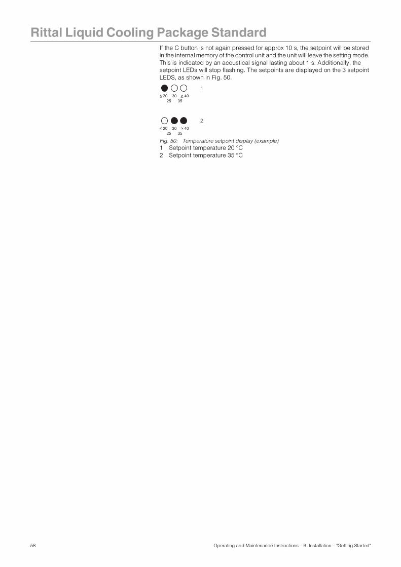
Rittal Liquid Cooling Package Standard
If the C button is not again pressed for approx 10 s, the setpoint will be stored in the internal memory of the control unit and the unit will leave the setting mode. This is indicated by an acoustical signal lasting about 1 s. Additionally, the setpoint LEDs will stop flashing. The setpoints are displayed on the 3 setpoint LEDS, as shown in Fig. 50.Fig. 50: Temperature setpoint display (example)1 Setpoint temperature 20 °C2 Setpoint temperature 35 °C
< 20 > 4035
3025
< 20 > 4035
3025
1
2
58 Operating and Maintenance Instructions – 6 Installation – "Getting Started"
Rittal Liquid Cooling Package Standard
6.7 Extended options byconnecting a Computer Multi Control – Top Concept (CMC-TC)
By connecting a Computer Multi Control – Top Concept/Processing Unit (CMC-TC/PU) to the Liquid Cooling Package control unit, you are able to call up various measurements and warning or alarm messages. These may then be further processed (e.g. by a Web browser, SNMP, SMS, etc.). Furthermore, various values can be set by using the CMC and then sent to the control unit. If a CMC is connected to the control unit, the green LED flashes in the same rhythm as the CMC is polling over the RS422 interface. The installation of a CMC allows for the connection and polling of a total of four control units.
The following values are polled and processed by the CMC: - Actual temperature
(average value of the cold air temperature, as determined by the control unit, which is used to regulate)
- Cooling capacity(calculated thermal output which is removed from the server enclosure)
- Alarm and warning messages (messages which give further information concerning the cause of a warning or an alarm)
The following values can be edited using the browser window of the CMC software and then sent to the control unit.- Setpoint temperature
(from the control unit to regulate the setpoint used)
- Hysteresis (hysteresis value for the control (standard = 3 K))
Additionally, the CMC polls some values, which are shown in the CMC browser window as information only.- Setpoint fan speed/magnetic valve
(the fan setting determined by the control unit for the fan module as well as the position of the magnetic valve (open/closed))
- Actual temperature/fan speeds (temperature level measured behind the heat exchanger (cold air temperature) as well as the actual fan speed of the fans for each fan module)
- Inlet/return temperature/Flow volume (the values of the inlet and return temperatures as reported by the heat exchanger module as well as the flow volume in l/min)
59 Operating and Maintenance Instructions – 6 Installation – "Getting Started"
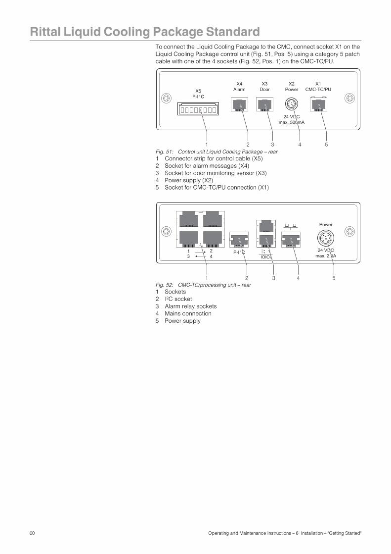
Rittal Liquid Cooling Package Standard
To connect the Liquid Cooling Package to the CMC, connect socket X1 on the Liquid Cooling Package control unit (Fig. 51, Pos. 5) using a category 5 patch cable with one of the 4 sockets (Fig. 52, Pos. 1) on the CMC-TC/PU.Fig. 51: Control unit Liquid Cooling Package – rear1 Connector strip for control cable (X5)2 Socket for alarm messages (X4)3 Socket for door monitoring sensor (X3)4 Power supply (X2)5 Socket for CMC-TC/PU connection (X1)
Fig. 52: CMC-TC/processing unit – rear1 Sockets2 I2C socket 3 Alarm relay sockets4 Mains connection5 Power supply
X3Door
X4Alarm
X2Power
X1CMC-TC/PUX5
P-I C2
24 VDCmax. 500mA
1 2 3 4 5
Power
24 VDCmax. 2,5A
P-I C21 23 4 IOIOI
1
1 2 3 4 5
60 Operating and Maintenance Instructions – 6 Installation – "Getting Started"
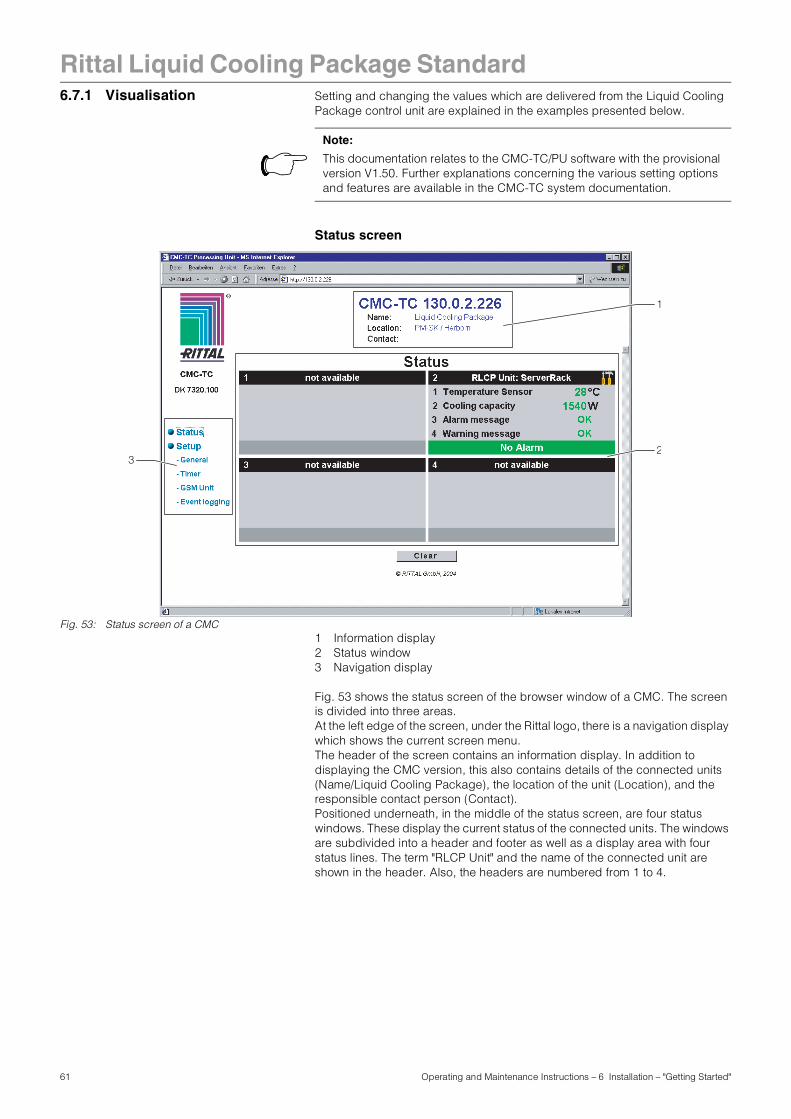
Rittal Liquid Cooling Package Standard
6.7.1 Visualisation Setting and changing the values which are delivered from the Liquid CoolingPackage control unit are explained in the examples presented below.
Status screen
Fig. 53: Status screen of a CMC1 Information display2 Status window3 Navigation display
Fig. 53 shows the status screen of the browser window of a CMC. The screen is divided into three areas. At the left edge of the screen, under the Rittal logo, there is a navigation display which shows the current screen menu. The header of the screen contains an information display. In addition to displaying the CMC version, this also contains details of the connected units (Name/Liquid Cooling Package), the location of the unit (Location), and the responsible contact person (Contact). Positioned underneath, in the middle of the status screen, are four status windows. These display the current status of the connected units. The windows are subdivided into a header and footer as well as a display area with four status lines. The term "RLCP Unit" and the name of the connected unit are shown in the header. Also, the headers are numbered from 1 to 4.
Note:
This documentation relates to the CMC-TC/PU software with the provisional version V1.50. Further explanations concerning the various setting options and features are available in the CMC-TC system documentation.
2
1
3
61 Operating and Maintenance Instructions – 6 Installation – "Getting Started"
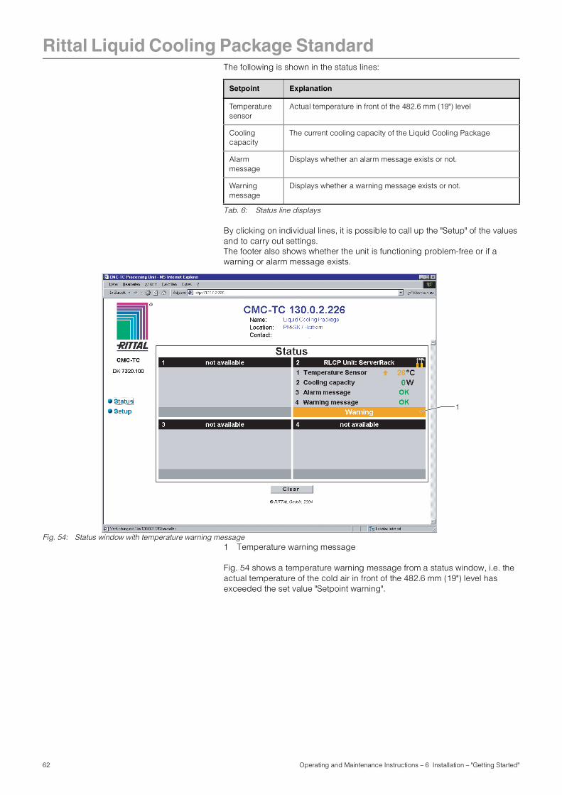
Rittal Liquid Cooling Package Standard
The following is shown in the status lines:Tab. 6: Status line displays
By clicking on individual lines, it is possible to call up the "Setup" of the values and to carry out settings.The footer also shows whether the unit is functioning problem-free or if a warning or alarm message exists.
Fig. 54: Status window with temperature warning message1 Temperature warning message
Fig. 54 shows a temperature warning message from a status window, i.e. the actual temperature of the cold air in front of the 482.6 mm (19") level has exceeded the set value "Setpoint warning".
Setpoint Explanation
Temperature sensor
Actual temperature in front of the 482.6 mm (19") level
Cooling capacity
The current cooling capacity of the Liquid Cooling Package
Alarm message
Displays whether an alarm message exists or not.
Warning message
Displays whether a warning message exists or not.
1
62 Operating and Maintenance Instructions – 6 Installation – "Getting Started"
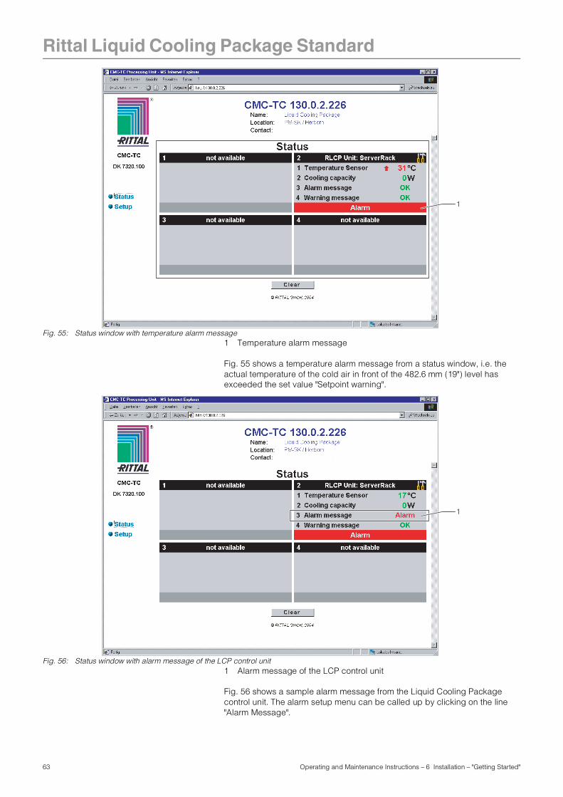
Rittal Liquid Cooling Package Standard
Fig. 55: Status window with temperature alarm message1 Temperature alarm message
Fig. 55 shows a temperature alarm message from a status window, i.e. the actual temperature of the cold air in front of the 482.6 mm (19") level has exceeded the set value "Setpoint warning".
Fig. 56: Status window with alarm message of the LCP control unit1 Alarm message of the LCP control unit
Fig. 56 shows a sample alarm message from the Liquid Cooling Package control unit. The alarm setup menu can be called up by clicking on the line "Alarm Message".
1
1
63 Operating and Maintenance Instructions – 6 Installation – "Getting Started"
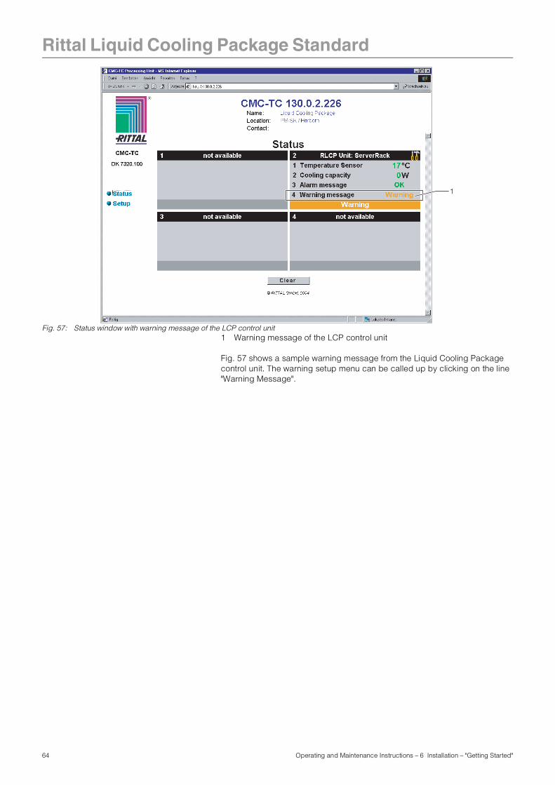
Rittal Liquid Cooling Package Standard
Fig. 57: Status window with warning message of the LCP control unit1 Warning message of the LCP control unit
Fig. 57 shows a sample warning message from the Liquid Cooling Package control unit. The warning setup menu can be called up by clicking on the line "Warning Message".
1
64 Operating and Maintenance Instructions – 6 Installation – "Getting Started"
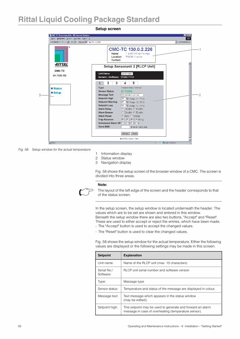
Rittal Liquid Cooling Package Standard
Setup screenFig. 58: Setup window for the actual temperature1 Information display2 Status window3 Navigation display
Fig. 58 shows the setup screen of the browser window of a CMC. The screen is divided into three areas.
In the setup screen, the setup window is located underneath the header. The values which are to be set are shown and entered in this window. Beneath the setup window there are also two buttons, "Accept" and "Reset". These are used to either accept or reject the entries, which have been made.- The "Accept" button is used to accept the changed values.
- The "Reset" button is used to clear the changed values.
Fig. 58 shows the setup window for the actual temperature. Either the following values are displayed or the following settings may be made in this screen.
2
1
3
Note:
The layout of the left edge of the screen and the header corresponds to that of the status screen.
Setpoint Explanation
Unit name: Name of the RLCP unit (max. 10 characters)
Serial No./Software:
RLCP unit serial number and software version
Type: Message type
Sensor status: Temperature and status of the message are displayed in colour.
Message text: Text message which appears in the status window(may be edited).
Setpoint high: This setpoint may be used to generate and forward an alarm message in case of overheating (temperature sensor).
65 Operating and Maintenance Instructions – 6 Installation – "Getting Started"
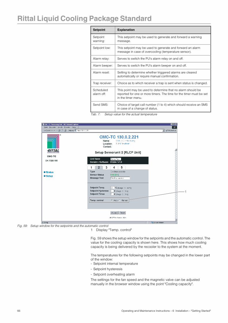
Rittal Liquid Cooling Package Standard
Tab. 7: Setup value for the actual temperature
Fig. 59: Setup window for the setpoints and the automatic control1 Display "Temp. control"
Fig. 59 shows the setup window for the setpoints and the automatic control. The value for the cooling capacity is shown here. This shows how much cooling capacity is being delivered by the recooler to the system at the moment.
The temperatures for the following setpoints may be changed in the lower part of the window: - Setpoint internal temperature
- Setpoint hysteresis
- Setpoint overheating alarm
The settings for the fan speed and the magnetic valve can be adjusted manually in the browser window using the point "Cooling capacity".
Setpointwarning:
This setpoint may be used to generate and forward a warning message.
Setpoint low: This setpoint may be used to generate and forward an alarm message in case of overcooling (temperature sensor).
Alarm relay: Serves to switch the PU's alarm relay on and off.
Alarm beeper: Serves to switch the PU's alarm beeper on and off.
Alarm reset: Setting to determine whether triggered alarms are cleared automatically or require manual confirmation.
Trap receiver: Choice as to which receiver a trap is sent when status is changed.
Scheduled alarm off:
This point may be used to determine that no alarm should be reported for one or more timers. The time for the timer must be set in the timer menu.
Send SMS: Choice of target call number (1 to 4) which should receive an SMS in case of a change of status.
Setpoint Explanation
1
66 Operating and Maintenance Instructions – 6 Installation – "Getting Started"
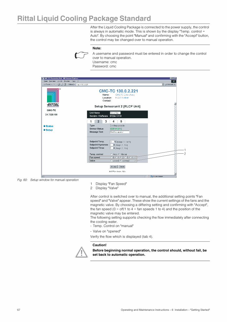
Rittal Liquid Cooling Package Standard
After the Liquid Cooling Package is connected to the power supply, the control is always in automatic mode. This is shown by the display "Temp. control = Auto". By choosing the point "Manual" and confirming with the "Accept" button, the control may be changed over to manual operation.Fig. 60: Setup window for manual operation1 Display "Fan Speed"2 Display "Valve"
After control is switched over to manual, the additional setting points "Fan speed" and "Valve" appear. These show the current settings of the fans and the magnetic valve. By choosing a differing setting and confirming with "Accept", the fan speed (0 = off/1 to 4 = fan speeds 1 to 4) and the position of the magnetic valve may be entered.The following setting supports checking the flow immediately after connecting the cooling water.- Temp. Control on "manual"
- Valve on "opened"
Verify the flow which is displayed (tab 4).
Note:
A username and password must be entered in order to change the control over to manual operation.Username: cmcPassword: cmc
12
Caution!
Before beginning normal operation, the control should, without fail, be set back to automatic operation.
67 Operating and Maintenance Instructions – 6 Installation – "Getting Started"
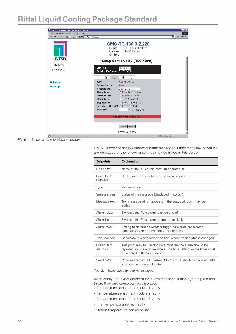
Rittal Liquid Cooling Package Standard
Fig. 61: Setup window for alarm messages
Fig. 61 shows the setup window for alarm messages. Either the following values are displayed or the following settings may be made in this screen.
Tab. 8: Setup value for alarm messages
Additionally, the exact cause of the alarm message is displayed in plain text (more than one cause can be displayed). - Temperature sensor fan module 1 faulty
- Temperature sensor fan module 2 faulty
- Temperature sensor fan module 3 faulty
- Inlet temperature sensor faulty
- Return temperature sensor faulty
Setpoints Explanation
Unit name: Name of the RLCP unit (max. 10 characters)
Serial No./Software:
RLCP unit serial number and software version
Type: Message type
Sensor status: Status of the message (displayed in colour).
Message text: Text message which appears in the status window (may be edited).
Alarm relay: Switches the PU's alarm relay on and off.
Alarm beeper: Switches the PU's alarm beeper on and off.
Alarm reset: Setting to determine whether triggered alarms are cleared automatically or require manual confirmation.
Trap receiver: Choice as to which receiver a trap is sent when status is changed.
Scheduled alarm off:
This point may be used to determine that no alarm should be reported for one or more timers. The time setting for the timer must be entered in the timer menu.
Send SMS: Choice of target call number (1 to 4) which should receive an SMS in case of a change of status.
68 Operating and Maintenance Instructions – 6 Installation – "Getting Started"
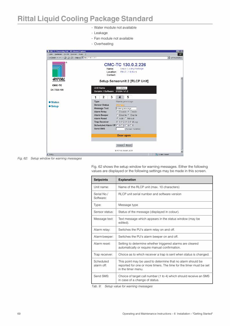
Rittal Liquid Cooling Package Standard
- Water module not available- Leakage
- Fan module not available
- Overheating
Fig. 62: Setup window for warning messages
Fig. 62 shows the setup window for warning messages. Either the following values are displayed or the following settings may be made in this screen.
Tab. 9: Setup value for warning messages
Setpoints Explanation
Unit name: Name of the RLCP unit (max. 10 characters)
Serial No./Software:
RLCP unit serial number and software version
Type: Message type
Sensor status: Status of the message (displayed in colour).
Message text: Text message which appears in the status window (may be edited).
Alarm relay: Switches the PU's alarm relay on and off.
Alarm beeper: Switches the PU's alarm beeper on and off.
Alarm reset: Setting to determine whether triggered alarms are cleared automatically or require manual confirmation.
Trap receiver: Choice as to which receiver a trap is sent when status is changed.
Scheduled alarm off:
This point may be used to determine that no alarm should be reported for one or more timers. The time for the timer must be set in the timer menu.
Send SMS: Choice of target call number (1 to 4) which should receive an SMS in case of a change of status.
69 Operating and Maintenance Instructions – 6 Installation – "Getting Started"
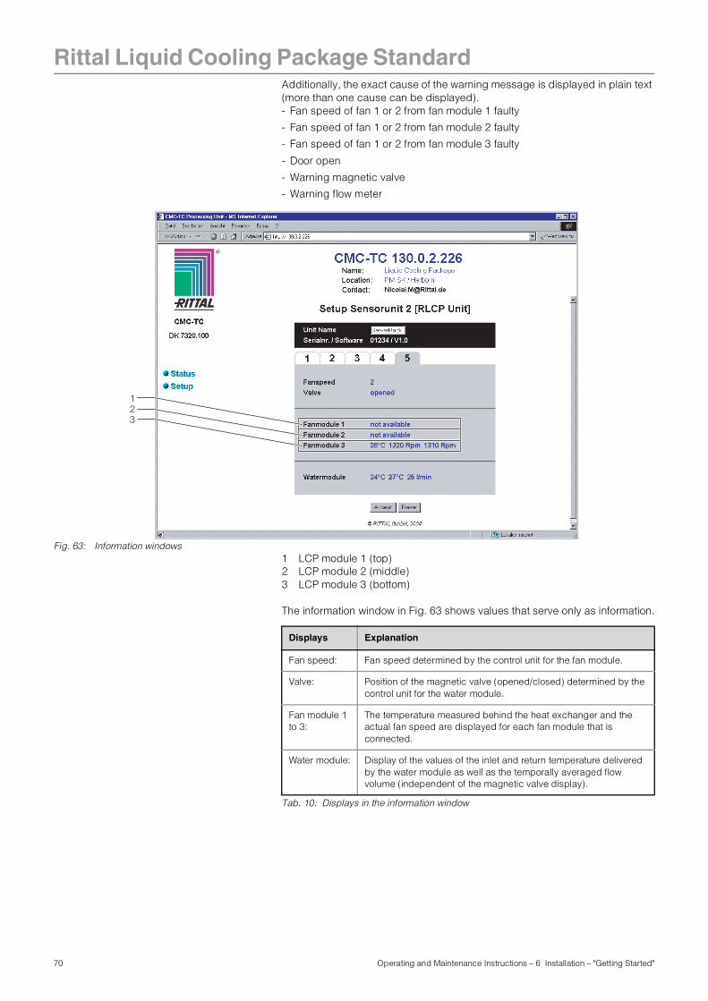
Rittal Liquid Cooling Package Standard
Additionally, the exact cause of the warning message is displayed in plain text (more than one cause can be displayed).- Fan speed of fan 1 or 2 from fan module 1 faulty- Fan speed of fan 1 or 2 from fan module 2 faulty
- Fan speed of fan 1 or 2 from fan module 3 faulty
- Door open
- Warning magnetic valve
- Warning flow meter
Fig. 63: Information windows1 LCP module 1 (top)2 LCP module 2 (middle)3 LCP module 3 (bottom)
The information window in Fig. 63 shows values that serve only as information.
Tab. 10: Displays in the information window
321
Displays Explanation
Fan speed: Fan speed determined by the control unit for the fan module.
Valve: Position of the magnetic valve (opened/closed) determined by the control unit for the water module.
Fan module 1 to 3:
The temperature measured behind the heat exchanger and the actual fan speed are displayed for each fan module that is connected.
Water module: Display of the values of the inlet and return temperature delivered by the water module as well as the temporally averaged flow volume (independent of the magnetic valve display).
70 Operating and Maintenance Instructions – 6 Installation – "Getting Started"
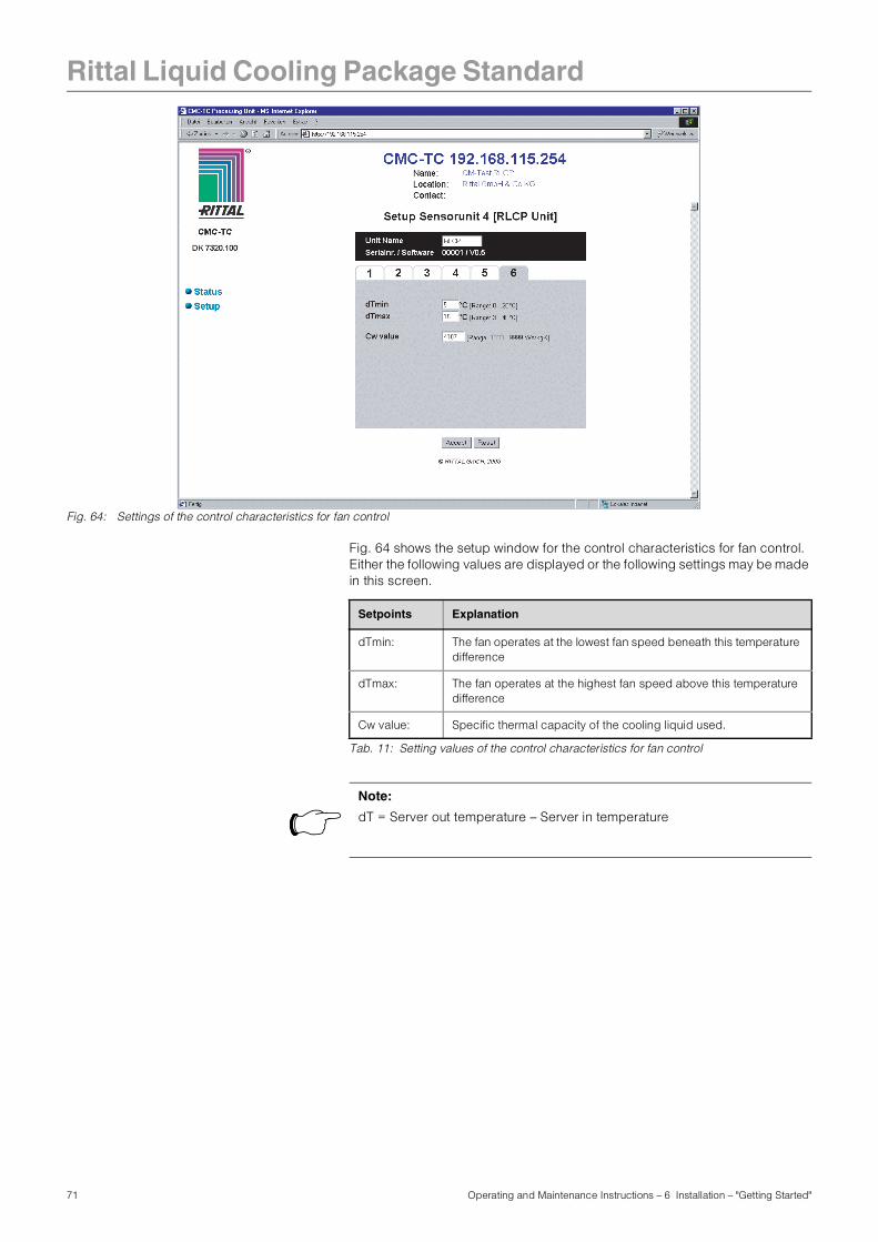
Rittal Liquid Cooling Package Standard
Fig. 64: Settings of the control characteristics for fan control
Fig. 64 shows the setup window for the control characteristics for fan control. Either the following values are displayed or the following settings may be made in this screen.
Tab. 11: Setting values of the control characteristics for fan control
Setpoints Explanation
dTmin: The fan operates at the lowest fan speed beneath this temperature difference
dTmax: The fan operates at the highest fan speed above this temperature difference
Cw value: Specific thermal capacity of the cooling liquid used.
Note:
dT = Server out temperature – Server in temperature
71 Operating and Maintenance Instructions – 6 Installation – "Getting Started"
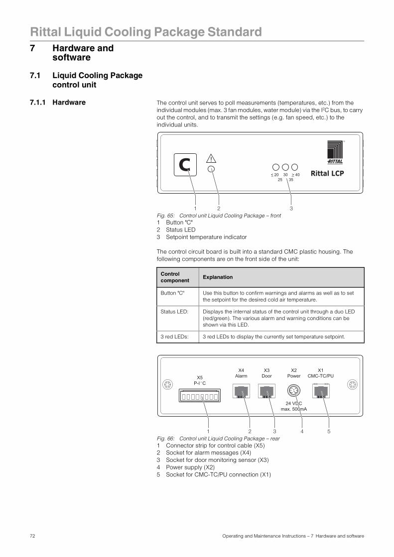
Rittal Liquid Cooling Package Standard
7 Hardware andsoftware
7.1 Liquid Cooling Package control unit
7.1.1 Hardware The control unit serves to poll measurements (temperatures, etc.) from the individual modules (max. 3 fan modules, water module) via the I2C bus, to carry out the control, and to transmit the settings (e.g. fan speed, etc.) to the individual units.
Fig. 65: Control unit Liquid Cooling Package – front1 Button "C"2 Status LED3 Setpoint temperature indicator
The control circuit board is built into a standard CMC plastic housing. The following components are on the front side of the unit:
Fig. 66: Control unit Liquid Cooling Package – rear1 Connector strip for control cable (X5)2 Socket for alarm messages (X4)3 Socket for door monitoring sensor (X3)4 Power supply (X2)5 Socket for CMC-TC/PU connection (X1)
Control component
Explanation
Button "C" Use this button to confirm warnings and alarms as well as to set the setpoint for the desired cold air temperature.
Status LED: Displays the internal status of the control unit through a duo LED (red/green). The various alarm and warning conditions can be shown via this LED.
3 red LEDs: 3 red LEDs to display the currently set temperature setpoint.
Rittal LCP< 20 > 4035
3025
!C
1 2 3
X3Door
X4Alarm
X2Power
X1CMC-TC/PUX5
P-I C2
24 VDCmax. 500mA
1 2 3 4 5
72 Operating and Maintenance Instructions – 7 Hardware and software
Rittal Liquid Cooling Package Standard
Various sockets are found on the rear side of the control unit.The 8-pole connector X5 (AMP MTA-plug connector 640457-8) contains the so-called Power-I2C bus.Assignment of the I2C bus:1 - N/C2 - Gnd3 - N/C4 - Gnd5 - Gnd6 - + 24 V7 - P-SDA8 - P-SCLA standard access sensor (DK 7320.530) for monitoring one or more doors may be connected through the RJ12 socket X3. If no access sensor is connected, a jumper (pin 2-6) must be put into place to prevent an error message.
To signal an alarm, the control unit includes both a beeper and an alarm relay. An external alarm may be connected to the unit via the RJ12 socket X4. X4 pin assignment:1 - Relay NO2 - Relay COMMON3 - Relay NC4 - N/C5 - Gnd6 - + 24 V
A cable for connecting an external alarm system is optionally available (DK 7200.430).
The connection to the CMC-TC processing unit is carried out through a RS422 connection over the RJ45 socket X2.X2 pin assignment:1 - R+2 - R-3 - + 24 V4 - Gnd5 - Gnd6 - + 24 V7 - T+8 - T-
24 V DC power may be supplied to the control unit or all modules in stand-alone operation through a separate power pack (DK 7320.425) and through a Kycon socket. When operating with a CMC-TC system, the system is supplied by power from the CMC power pack.
73 Operating and Maintenance Instructions – 7 Hardware and software
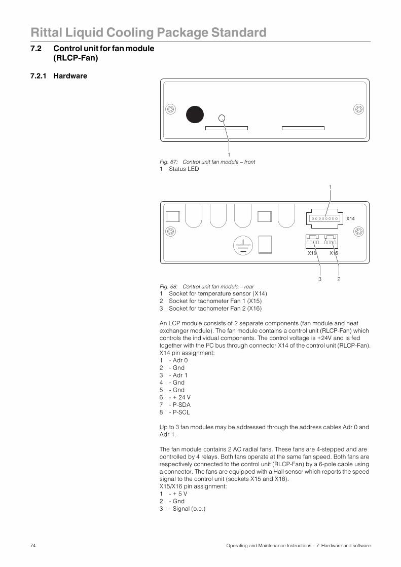
Rittal Liquid Cooling Package Standard
7.2 Control unit for fan module(RLCP-Fan)
7.2.1 Hardware
Fig. 67: Control unit fan module – front1 Status LED
Fig. 68: Control unit fan module – rear1 Socket for temperature sensor (X14)2 Socket for tachometer Fan 1 (X15)3 Socket for tachometer Fan 2 (X16)
An LCP module consists of 2 separate components (fan module and heat exchanger module). The fan module contains a control unit (RLCP-Fan) which controls the individual components. The control voltage is +24V and is fed together with the I2C bus through connector X14 of the control unit (RLCP-Fan).X14 pin assignment:1 - Adr 02 - Gnd3 - Adr 14 - Gnd5 - Gnd6 - + 24 V7 - P-SDA8 - P-SCL
Up to 3 fan modules may be addressed through the address cables Adr 0 and Adr 1.
The fan module contains 2 AC radial fans. These fans are 4-stepped and are controlled by 4 relays. Both fans operate at the same fan speed. Both fans are respectively connected to the control unit (RLCP-Fan) by a 6-pole cable using a connector. The fans are equipped with a Hall sensor which reports the speed signal to the control unit (sockets X15 and X16).X15/X16 pin assignment:1 - + 5 V2 - Gnd3 - Signal (o.c.)
1
X16
X14
X15
1
3 2
74 Operating and Maintenance Instructions – 7 Hardware and software
Rittal Liquid Cooling Package Standard
Further, the control unit has 3 connectors (X13 to X14) which evaluate the temperature sensors. These are located in the heat exchanger module and lead from there to the control unit. These sensors measure the air temperature behind the heat exchanger (i.e. the air that is fed into the server enclosure).The control unit includes an LED which displays the internal status.
7.2.2 Software The LCP module's software continuously reads the analogue values from the three temperature sensors via the analogue channel and establishes an average value for each sensor. Next, it reads the temperature value in °C from a table and writes this in the I2C transmission buffer.
Further, the software counts the speed pulses of both fans in a module and also writes this into the I2C transmission buffer. The fan set speed determined by the control unit is evaluated and the appropriate fan speed is set on the fans via relays. An LED on the fan module shows an error code, which is indicated by short flash pulses. 0 no error (LED constantly on). The I2C data traffic is indicated as the LED is
briefly extinguished when a data packet is requested.1 Temperature sensor defect2 Fan speed error fan 13 Fan speed error fan 24 I2C timeout (approx. 20 s)
The measurements are cyclically requested by the Liquid Cooling Package control unit over the I2C bus and new settings are sent to the LCP module. The data are designed as follows
Command: Poll measurement data from the fan module.
The control unit addresses one of the three fan modules (addresses 70H, 72H or 74H). The fan modules reply with the following data string:
Telegram length: 8 characters
"A" Tmp1 Tmp2 Tmp3 Sp1 Sp2 Status Chk
Information block Explanation
Protocol ID:("A")
"A" is currently used as ID
Temperatures:(Tmp1, Tmp2 and Tmp3)
The fan module can process up to 3 temperature sensors. However, only one temperature sensor is currently being used (Tmp1). The temperatures can assume the following values:- 0...60: Temperature valid
(corresponds to 0°C ... 60°C)
- 254: Possibly no sensor connection or sensor failure
- 255: Sensor input short circuited
Speeds:(Sp1 and Sp2)
These two bytes deliver the fan speed values of both fan motors. The fan speed pulses from the fans are measured for 6 s. Thus, if the fan speed in RPM is to be later displayed on the website, this value should be multiplied by 10.
Status byte:(Status)
This byte currently contains no data
Check sum(Chk)
Sum of bytes 1 to 6
75 Operating and Maintenance Instructions – 7 Hardware and software
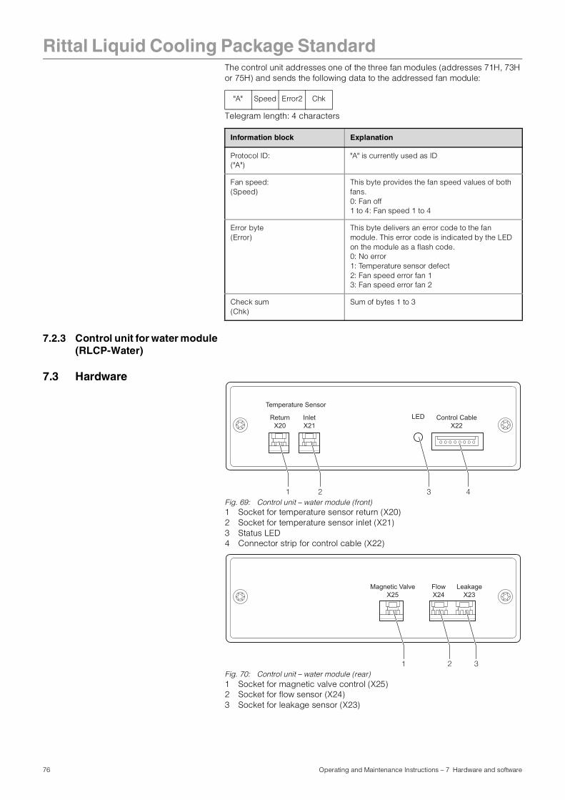
Rittal Liquid Cooling Package Standard
The control unit addresses one of the three fan modules (addresses 71H, 73H or 75H) and sends the following data to the addressed fan module:Telegram length: 4 characters
7.2.3 Control unit for water module (RLCP-Water)
7.3 Hardware
Fig. 69: Control unit – water module (front)1 Socket for temperature sensor return (X20)2 Socket for temperature sensor inlet (X21)3 Status LED4 Connector strip for control cable (X22)
Fig. 70: Control unit – water module (rear)1 Socket for magnetic valve control (X25)2 Socket for flow sensor (X24)3 Socket for leakage sensor (X23)
"A" Speed Error2 Chk
Information block Explanation
Protocol ID:("A")
"A" is currently used as ID
Fan speed:(Speed)
This byte provides the fan speed values of both fans.0: Fan off1 to 4: Fan speed 1 to 4
Error byte(Error)
This byte delivers an error code to the fan module. This error code is indicated by the LED on the module as a flash code.0: No error 1: Temperature sensor defect2: Fan speed error fan 13: Fan speed error fan 2
Check sum(Chk)
Sum of bytes 1 to 3
LED
Temperature Sensor
Return X20
InletX21
Control CableX22
1 2 3 4
FlowX24
Magnetic ValveX25
LeakageX23
1 2 3
76 Operating and Maintenance Instructions – 7 Hardware and software
Rittal Liquid Cooling Package Standard
The water unit also contains a control unit (RLCP-Water). The control voltage is +24V and is fed together with the I2C bus through connector X2 of the control unit (RLCP-Water).The water module is addressed through the address cables Adr 0 and Adr 1.The control unit has 2 connectors (X20 and X21) which evaluate the temperature sensors (NTC103AT). Both of these sensors are used to measure the inlet and return water temperature.
The water flow can be opened or closed via a magnetic valve (+24 V DC/open at zero voltage). This valve is controlled by a transistor output (o.c.) through connector X25.X25 pin assignment:1 - + 24 V DC2 - output (o.c.)
The water flow is measured by a flow sensor. This sensor is equipped with a Hall sensor, which reports 67 pulses per litre to the control unit (X24). X24 pin assignment:1 - + 5 V2 - Gnd3 - Signal (o.c.)
Further, the control unit (RLCP-Water) has an input X23 to evaluate the signal from a leakage detector. A sensor of the type LLE105000 is used in the water module.X23 pin assignment:1 - + 5 V2 - Gnd3 - Signal (o.c.)
The control unit includes an LED which displays the internal status.
7.3.1 Software The water module's software continuously reads the analogue values from the two temperature sensors for the inlet and return of the cooling water system via the analogue channel of the CPU and establishes an average value for each sensor. Next, it reads the temperature value in °C from a table and writes this in the I2C transmission buffer.
Further, the software counts the pulses from the flow meter, reads the leakage sensor and the digital input, and writes these values in the I2C transmission buffer. The position of the magnetic valve (opened/closed) is determined by the control unit. An LED on the water module shows an error code, which is indicated by short flash pulses. 0 no error (LED constantly on). The I2C data traffic is indicated as the LED is
briefly extinguished when a data packet is requested. 1 Leakage 2 Inlet temperature sensor faulty 3 Return temperature sensor faulty 4 I2C timeout (approx. 20 s)
The measurements are cyclically requested by the Liquid Cooling Package control unit over the I2C bus and new settings are sent to the water module. These data are designed as follows:
Command: Poll measurement data from the water module.
The control unit addresses the water module (Address 76H). The water module replies with the following data string:
Telegram length: 8 characters
"B" Tmp1 Tmp2 FlH FlL Res Status Chk
77 Operating and Maintenance Instructions – 7 Hardware and software
Rittal Liquid Cooling Package Standard
The control unit addresses the water module (address 76H) and sends the following data.
Telegram length: 4 characters
Information block Explanation
Protocol ID:("B")
"B" is currently used as ID
Temperatures:(Tmp1 and Tmp2)
The water unit can process 2 temperature sensors. These are used to measure the water temperature (Tmp1 = inlet/Tmp2 = return). The temperatures can assume the following values:- 0 to 60: Temperature valid
(corresponds to 0°C to 60°C)
- 254: Possibly no sensor connection or sensor failure
- 255: Sensor input short circuited
Flow counter(FlH and FlL)
These two bytes contain the pulse value for the flow sensor (High byte/Low byte). The pulses from the flow sensor are continuously added up and are not reset until they are reported to the control unit.
Status byte:(Status)
This byte shows the status of the leakage input and the digital input:- Bit 0: Status of digital input
(0 = shut/1 = open)
- Bit 1: Status leakage sensor (0 = Leakage/1 = open)
- Bit 2 to 7: Reserved
Check sum(Chk)
Sum of bytes 1 to 6
"B" MV Error Chk
Information block Explanation
Protocol ID:("B")
"B" is currently used as ID
Magnetic valve(MV)
This byte indicates if the magnetic valve should be opened or closed:0: Valve off (open)1: Valve on (closed)
Error byte(Error)
This byte delivers an error code to the water module. This error code is indicated by the LED on the module as a flash code.0: No error 1: Leakage 2: Inlet temperature sensor faulty3: Return temperature sensor faulty
Check sum(Chk)
Sum of bytes 1 to 3
78 Operating and Maintenance Instructions – 7 Hardware and software
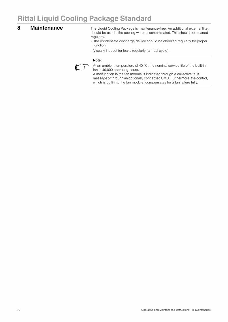
79 Operating and Maintenance Instructions – 8 Maintenance
Rittal Liquid Cooling Package Standard8 Maintenance The Liquid Cooling Package is maintenance-free. An additional external filter
should be used if the cooling water is contaminated. This should be cleaned regularly.- The condensate discharge device should be checked regularly for proper
function.
- Visually inspect for leaks regularly (annual cycle).
Note:
At an ambient temperature of 40 °C, the nominal service life of the built-in fan is 40,000 operating hours.A malfunction in the fan module is indicated through a collective fault message or through an optionally connected CMC. Furthermore, the control, which is built into the fan module, compensates for a fan failure fully.
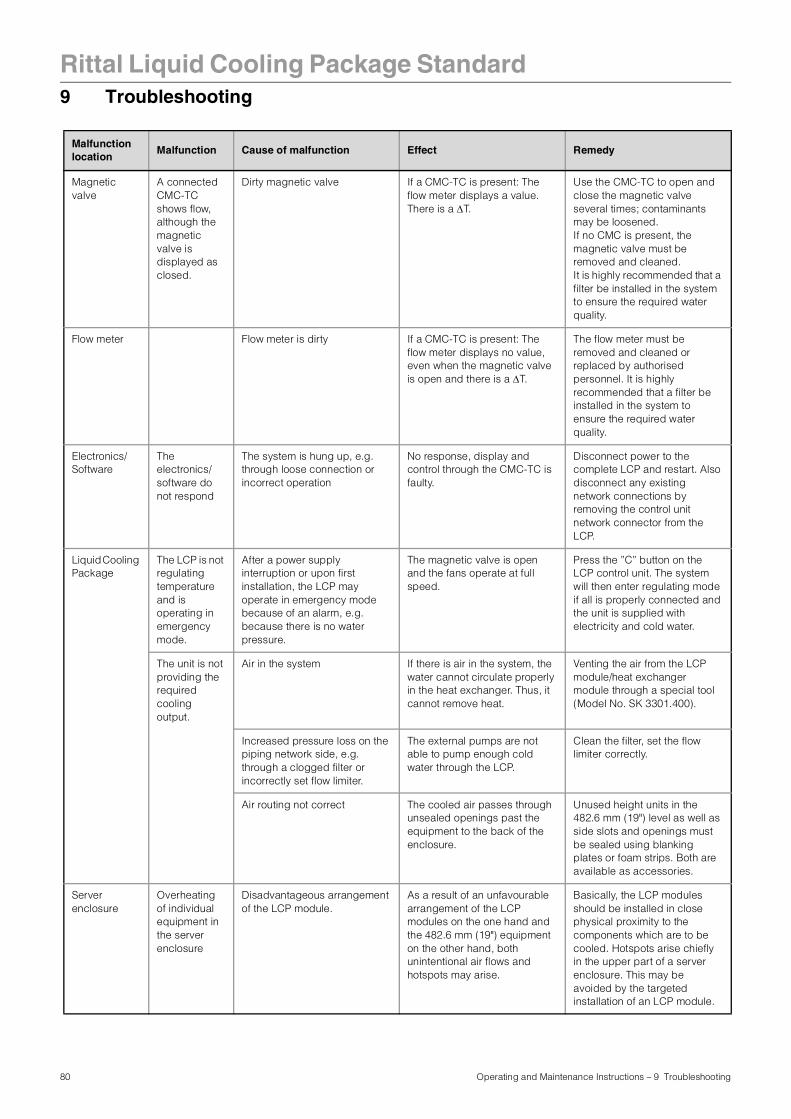
Rittal Liquid Cooling Package Standard
9 TroubleshootingMalfunction location
Malfunction Cause of malfunction Effect Remedy
Magnetic valve
A connected CMC-TC shows flow, although the magnetic valve is displayed as closed.
Dirty magnetic valve If a CMC-TC is present: The flow meter displays a value. There is a ∆T.
Use the CMC-TC to open and close the magnetic valve several times; contaminants may be loosened.If no CMC is present, the magnetic valve must be removed and cleaned. It is highly recommended that a filter be installed in the system to ensure the required water quality.
Flow meter Flow meter is dirty If a CMC-TC is present: The flow meter displays no value, even when the magnetic valve is open and there is a ∆T.
The flow meter must be removed and cleaned or replaced by authorised personnel. It is highly recommended that a filter be installed in the system to ensure the required water quality.
Electronics/Software
The electronics/software do not respond
The system is hung up, e.g. through loose connection or incorrect operation
No response, display and control through the CMC-TC is faulty.
Disconnect power to the complete LCP and restart. Also disconnect any existing network connections by removing the control unit network connector from the LCP.
Liquid Cooling Package
The LCP is not regulating temperature and is operating in emergency mode.
After a power supply interruption or upon first installation, the LCP may operate in emergency mode because of an alarm, e.g. because there is no water pressure.
The magnetic valve is open and the fans operate at full speed.
Press the ”C” button on the LCP control unit. The system will then enter regulating mode if all is properly connected and the unit is supplied with electricity and cold water.
The unit is not providing the required cooling output.
Air in the system If there is air in the system, the water cannot circulate properly in the heat exchanger. Thus, it cannot remove heat.
Venting the air from the LCP module/heat exchanger module through a special tool (Model No. SK 3301.400).
Increased pressure loss on the piping network side, e.g. through a clogged filter or incorrectly set flow limiter.
The external pumps are not able to pump enough cold water through the LCP.
Clean the filter, set the flow limiter correctly.
Air routing not correct The cooled air passes through unsealed openings past the equipment to the back of the enclosure.
Unused height units in the 482.6 mm (19") level as well as side slots and openings must be sealed using blanking plates or foam strips. Both are available as accessories.
Server enclosure
Overheating of individual equipment in the server enclosure
Disadvantageous arrangement of the LCP module.
As a result of an unfavourable arrangement of the LCP modules on the one hand and the 482.6 mm (19") equipment on the other hand, both unintentional air flows and hotspots may arise.
Basically, the LCP modules should be installed in close physical proximity to the components which are to be cooled. Hotspots arise chiefly in the upper part of a server enclosure. This may be avoided by the targeted installation of an LCP module.
80 Operating and Maintenance Instructions – 9 Troubleshooting
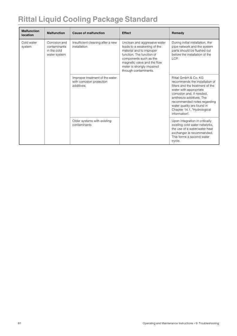
Rittal Liquid Cooling Package Standard
Cold water system
Corrosion and contaminants in the cold water system
Insufficient cleaning after a new installation
Unclean and aggressive water leads to a weakening of the material and to improper function. The function of components such as the magnetic valve and the flow meter is strongly impaired through contaminants.
During initial installation, the pipe network and the system parts should be flushed out before the installation of the LCP.
Improper treatment of the water with corrosion protection additives.
Rittal GmbH & Co. KG recommends the installation of filters and the treatment of the water with appropriate corrosion and, if needed, antifreeze additives. The recommended notes regarding water quality are found in Chapter 14.1, "Hydrological information".
Older systems with existing contaminants
Upon integration in critically existing cold water networks, the use of a water/water heat exchanger is recommended. This forms a second water cycle.
Malfunction location
Malfunction Cause of malfunction Effect Remedy
81 Operating and Maintenance Instructions – 9 Troubleshooting
Rittal Liquid Cooling Package Standard
10 Frequently askedquestions (FAQ)
In what output ranges is the Rittal Liquid Cooling Package available?
The cooling output of an air/water heat exchanger is basically dependent on the inlet temperature and volumetric flow of the water as well as the air throughput achieved by the fans which are used. With the standard settings of 15 °C water inlet at 15 l/min/module, cooling outputs of 4, 8 and 12 kW are achieved. If the water inlet temperature is reduced, for example, to 6 °C, the cooling output is increased to approx. 20 kW. In correctly assessing the information, it is important to note at what ∆T (at what temperature differential between server air inlet and server air outlet) these values were reported. Modern servers such as 1 HU-Dual CPU systems or blade servers can have a ∆T of up to 25 °C. Please note the recommendations of the server manufacturer.
Are special components required for use with the Liquid Cooling Package?
All components that follow the "front to back" cooling principle (99% of IT equipment) may be used without restriction in connection with the Liquid Cooling Package. Every Rittal server rack which was previously cooled conventionally may be cooled with a Liquid Cooling Package after changing to sealed doors. In other words, it is possible to retrofit standard racks and bay them onto the Liquid Cooling Package. The server enclosure remains unaffected by the side installation of the Liquid Cooling Package. All height units remain fully usable in their complete depth. Further, by locating the foam strips appropriately, sufficient cooling is also possible for devices which require sideways air throughput (e.g. switches).
Is the ambient air heated by additional heat coming out of these enclosures?
The cooling system in the enclosure works completely independently of the ambient air. All waste heat is transferred externally through the cooling water circuit.
May the quantity of heat removed be controlled dependent on the heat loss?
The controlled variable for the Liquid Cooling Package is the temperature of the air blown in in front of the 482.6 mm (19") level. The values to be used here are available in the manufacturer's instruction manual. Upon installation, the desired setpoint temperature is set once on the Liquid Cooling Package (or through the optionally available CMC). This value will be kept constant, independent of the cooling output demands. This occurs through the corresponding automatic opening and closing of the magnetic valve. Additionally, the necessary fan output is adjusted based on the air inlet and exhaust temperatures of the server. In this manner, the Liquid Cooling Package always cools only as much as is necessary without wasting energy. Further, this avoids problems arising from condensation and desiccation which results from overcooling.
How is the airflow in the enclosure achieved and what advantages does this have?
As a general rule, the "front to back" principle is used in server enclosures. Cold air is supplied to the front of the enclosure. The units built into the enclosure have their own fans, which draw in this air and use it internally for cooling. Thus heated, it is exhausted to the rear side. The special horizontal air routing of the Liquid Cooling Package, which is adapted especially to this widespread cooling principle, evenly supplies cooled air to the complete height of the server enclosure. That means that all units, independent of their installation position in the enclosure and their charge state, receive sufficient cold air. Temperature gradients are avoided, so that an extremely high cooling capacity can be achieved for each enclosure.
Note:
This chapter contains only a selection of the frequently asked questions (FAQ) Further FAQs may be found on our website: www.rimatrix5.com
82 Operating and Maintenance Instructions – 10 Frequently asked questions (FAQ)
Rittal Liquid Cooling Package Standard
Can the Liquid Cooling Package be operated when the doors are opened?The response of the Liquid Cooling Package upon operation with opened doors depends chiefly upon the prevailing ambient conditions. If a front door is opened, the cool air is mixed marginally with the ambient air. Thus, no cooling problems are expected in air conditioned rooms. Overall, no heat is carried into the room. The back door should only be opened for a short while during operation, since this breaks the cooling air circuit, resulting that the waste heat is carried into the room. However, this does not influence the cooling of the units in the enclosure.
Why is the Liquid Cooling Package, as an air/water heat exchanger, installed on the side panel?
It was important to develop a high performance cooling system which would also meet the requirements of the coming years. This could only be achieved routing the cooling air in a manner which was tailored to the needs of the devices. The chief problem encountered when cooling with air from the raised floor, or with roof or floor heat exchangers is the air flow. Cold air which is fed into the enclosure from below or above changes its temperature greatly because of recirculation. Temperature differentials of up to 20 °C were measured from "below" to "above" in enclosures found in data centres. Thus, a server installed "below" in an enclosure may have temperature conditions of up to 20 °C "better" than one installed "above" in an enclosure. Because of this, in order to achieve sufficient cooling of all systems in the enclosure when using this sort of cooling, a significantly lower air temperature must be used. When cooling air is provided from the side, this problem does not even arise. Cooling is more effective and more exact because the air supplied to the units can be held within 1-2 °C. Because the system is built as its own enclosure, the system is consequently protected against the risk of leaks. All water-carrying parts are located outside of the actual server enclosure. Connection to the cooling water network also is made in the floor there. Further, Rittal has many years of experience in the field of air/water heat exchangers. All of this experience is incorporated into the construction of the Liquid Cooling Package. Because of these precautionary measures, even in the event of a – itself very unlikely – leak, water cannot find its way into the area for electronic components. Because of its "thin" profile of just 300 mm, the pattern achieved in the data centre is not interrupted. Because the depth of the enclosures is not increased, the full width of the walkways in the data centre is maintained.
How is water connected to the Liquid Cooling Package?
For easy installation, connection to the building system or the recooler is made, as desired, from below or from the rear with 3/4" threaded connections. Of course, these may be exchanged with quick release fastenings.
Can both air-cooled and water-cooled server enclosures operate side-by-side in a data centre?
Of course. There must only be a cooling water installation available for the water-cooled enclosures. The advantage of this is that the existing room air conditioning is not further burdened. Thereby, Liquid Cooling Package Systems can be used to intercept "hotspots" in the data centre without requiring the expansion of the air conditioning system.
With which dimensions is the Liquid Cooling Package usable?
The Liquid Cooling Package itself has the dimensions W x H x D 300 x 2000 x 1000 mm. Every Rittal enclosure with the dimensions H x D 2000 x 1000 mm, independent of width, can be bayed. Other sizes available on request.
Two fans are built into each module in the Liquid Cooling Package. May one fan also be used to remove the nominal rated heat load?
The fans are not completely redundantly designed, i.e. one alone is sufficient to operate the system only for a certain time. This length of time is dependent on the number of modules installed and the heat loss. (With 3 modules, and thus 6 fans – or 5 fans in the event of a malfunction, the system is practically unaffected.) A slight rise in the inner temperature of the enclosure may occur. The control electronics recognise this situation and independently adjust the fan speed of the remaining fans. In case of a malfunction, the Liquid Cooling Package can generate a message through the alarm output of the control unit. In connection with the CMC, all system-relevant parameters (water: inlet/return temperature, flow, leakage; air: temperature in front of and behind the servers; fans: speed; magnetic valve) are monitored and all options of the CMC are fully available.
83 Operating and Maintenance Instructions – 10 Frequently asked questions (FAQ)
Rittal Liquid Cooling Package Standard
Does the Liquid Cooling Package require maintenance?The Liquid Cooling Package is maintenance free. All components are designed with an extremely long lifespan. In case of a malfunction a message is generated through the alarm output of the control unit or through the CMC.
What advantages does a water-cooled solution have over an air-cooled solution in a data centre?
The use of water-cooled enclosures allows for controlled, efficient and cost-saving cooling of heat losses, which was not possible with conventional air conditioning. Only thus, it is possible to fully use the space, which is physically available in the enclosures, instead of being forced to erect half-empty enclosures because of air conditioning problems. This achieves considerable savings in the investment and operating costs of a data centre.
Is a raised floor necessary for installation? If yes, what height is required?
A raised floor is not required for routing the cooling water pipes. In principle, the pipes can also be laid in channels in the floor. A main cooling pipe requires approx. 150 mm headroom in a raised floor; an enclosure supply line approx. 50 mm. With high-quality composite pipes, such as those used in underfloor heating, an extremely flexible routing of the cooling water pipelines is possible.
May LCP-cooled enclosures also be bayed with one another?
Basically, the Liquid Cooling Package is just a "small" enclosure. That means that all accessories for baying may be used. Thus, LCP-cooled systems may be bayed without limitation.
How is condensate formation prevented in the Liquid Cooling Package?
Condensation can only occur when air is significantly cooled below the ambient temperature. Thus, its capacity to absorb or "hold" water is reduced. In the norm, the Liquid Cooling Package works with water temperatures above the dewpoint. Condensate formation is thus excluded. If it is operated with lower temperatures, the control minimises condensate formation. Any arising condensate is effectively hindered from leaving the Liquid Cooling Package through design measures. These measures include suitable air routing, wipe-off grids and active condensate management. The user can choose if condensate is routed to the return or out of the Liquid Cooling Package through a condensate discharge.
How does the Liquid Cooling Package prevent desiccation?
At the same time that air is cooled, it is also dehumidified. Because of cable entry points, the system is not 100% sealed off from its surroundings. This small amount of exchange with external air is sufficient to hold the air's relative humidity above 30% and thus non-critical. At no time is there the danger of static charges arising in the enclosure.
Can the Liquid Cooling Package be operated together with the CPU cooling solution?
A combination of direct CPU cooling with water and the Liquid Cooling Package is always possible. Depending on the computer system, only up to 70% of the total heat loss is removed through the water heatsinks with direct CPU cooling. In cases of high cooling output requirements, this means that a combination of systems is even necessary. Please request our documentation for individual projects separately.
In case a pipe should break or burst, how is water entry into the server rack avoided?
Because the components are carefully chosen, it is practically impossible for a pipe to break. The base unit of each LCP module serves as a water collecting tray. These are connected to one another, so that any water arising is immediately led away through the condensate discharge. Through the physical separation of the Liquid Cooling Package from the server enclosure, it is always ensured that no water can enter into the server area. Additionally, the integrated leakage sensor reports even the smallest leak volumes to allow for a rapid response.
84 Operating and Maintenance Instructions – 10 Frequently asked questions (FAQ)
Rittal Liquid Cooling Package Standard
Why does the Liquid Cooling Package allow for the possibility of cooling one or two enclosures?The most important design principle was a flexible cooling system which would correspond to the enormous volume of air required by a modern server. Because of the horizontal cooling possibility, options for "right", left" or "both-sided" cooling arise in combination with the chosen fans. On the other hand, "moderate" cooling output requirements should also be achievable. That means, for example, that a Liquid Cooling Package equipped with one module is able to service two server enclosures with 2 kW heat loss each. In the same manner, a Liquid Cooling Package can be used to provide a cooling output of up to 20 kW per enclosure. In this manner, the Liquid Cooling Package covers a wide range of possible cooling outputs. This provides the customer a great deal of security for his/her investment, since the Liquid Cooling Package can "grow with".
Can a Liquid Cooling Package which has already been installed be retrofitted?
The Liquid Cooling Package is modularly conceived. That means that the cooling capacity can be expanded simply by "plugging in" an additional module in 4 kW steps at any time.
In which applications and situations should an air/water heat exchanger system be used?
Whenever the cooling capacity of the room air conditioning system is not sufficient to handle the heat loads of current high performance servers. With an optimal design in a newly planned data centre, this limit is at about 1,000 –1,200 W/m²; in older data centres, it is often significantly below that. At best, a maximum of 4 kW per rack needs to be removed. By contrast, racks which are filled with blade servers reach up to 17 kW. But the Liquid Cooling Package represents a possible solution even in applications where there is no existing air conditioning system. In combination with Rittal recooling systems, even climate control solutions for high performance cluster systems can be created.
What additional infrastructure is required to operate the system?
In addition to the Liquid Cooling Package, pipes to the individual enclosures and a system for generating the cooling water are required. With single enclosures, a direct connection with the cooling water is sufficient. With multiple enclosures, a cooling water distribution system, similar to a central heating distribution system, should be provided. To a great degree, this infrastructure corresponds to that which is already used in a conventionally air conditioned data centre. The "cold" water is provided by water chillers (with adequate redundancy, especially in regard to the pumps). The water is distributed over a cooling water network in the data centre to fan coil or ceiling cooling units.
What key disadvantages of today's air-cooled solutions are remedied by water cooling?
The chief problem of conventional cooling involves directing large amounts of cool air through raised floors, suspended ceilings and within the room. Often, because of complex flow conditions, the cold air does not reach the servers in sufficient quantities. There is actually enough cold produced; often, the cooling output from raised floor systems lies far above the electrically connected load of the unit, which needs to be cooled. In spite of this, the cooling is insufficient. This effect is explained by the fact that the cooling air is already warmed too much through recirculation on its way to the server. By using water to lead the heat loss out of the enclosure, an excellent separation between cold air and removed thermal energy is achieved. Because of its material characteristics, water can transport thermal energy almost 4,000 times "better" than air. Small pipes are capable of transporting very large quantities of heat.
Can accessories and other equipment from 482.6 mm (19") enclosures be used in conjunction with the Liquid Cooling Package?
The Liquid Cooling Package and the accompanying server enclosure are standard products within the Rittal family of enclosures. All components and accessory parts can be used without limitation.
Up to what depth may servers be installed?
Modern server systems may be up to 800 mm deep. Because of that, it is recommended that the 482.6 mm (19") level in the enclosure be installed so that the same distance remains to the door in front and in back. In combination with the space on the side between the 482.6 mm (19") level and the Liquid Cooling Package, sufficient room for the air which is fed or emitted is achieved. The side openings do not need to be completely open throughout their depth.
85 Operating and Maintenance Instructions – 10 Frequently asked questions (FAQ)
Rittal Liquid Cooling Package Standard
How does the Liquid Cooling Package respond to an elevated ambient temperature or fire?Because the closed design seals the system to the outside, even greatly increased ambient air temperatures are not a problem – as long as the cold water supply is functioning. This represents an effective protection against the effects of fire in case of a fire in the room. Smoke, corrosive gases, water steam and fire-fighting water are securely kept away. Only extremely high temperatures or direct exposure to flames would be critical, but the consequences of fire in the area or in the adjacent room are in any case restrained.
Does the maximum depth available for installed equipment correspond with the enclosure's depth?
Almost the entire depth of the enclosure can be used for installed equipment. No other space for installed mechanical equipment, e.g. fans, is required.
86 Operating and Maintenance Instructions – 10 Frequently asked questions (FAQ)
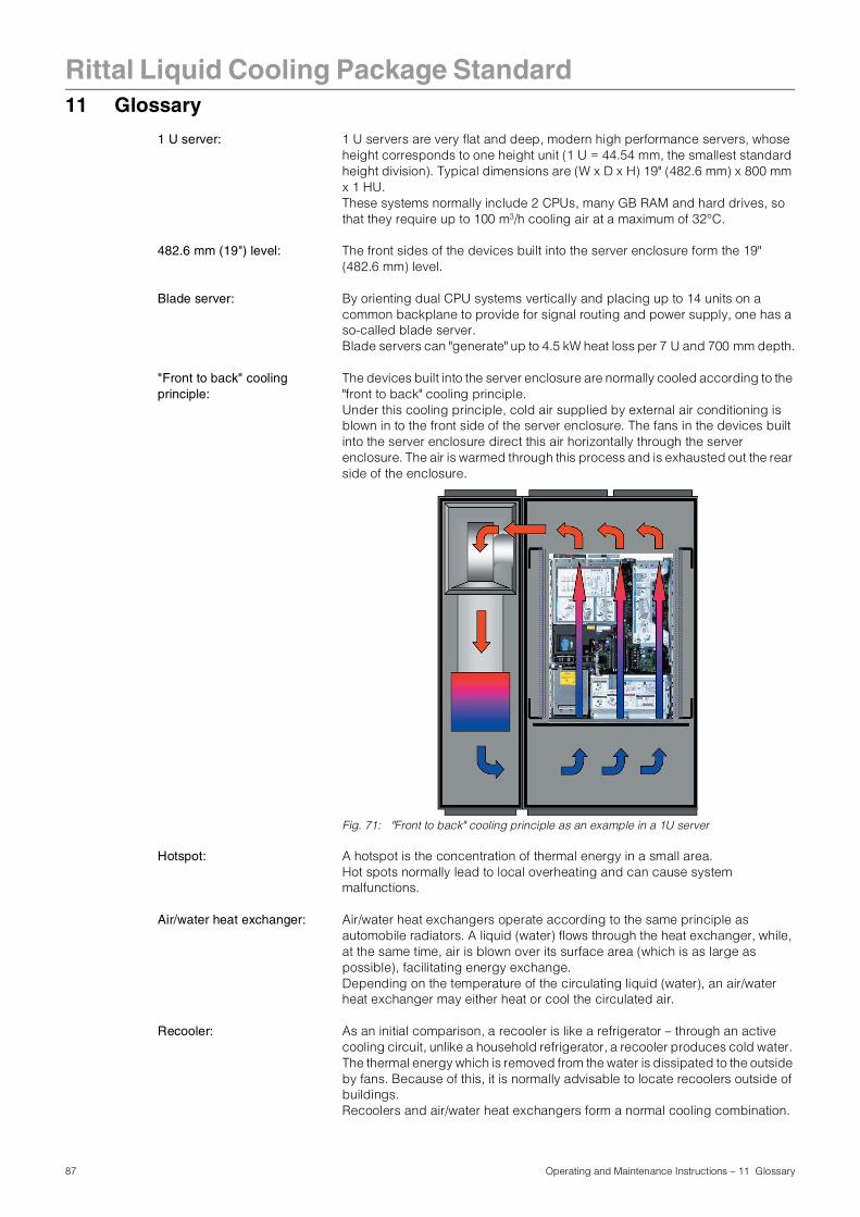
Rittal Liquid Cooling Package Standard
11 Glossary1 U server: 1 U servers are very flat and deep, modern high performance servers, whose height corresponds to one height unit (1 U = 44.54 mm, the smallest standard height division). Typical dimensions are (W x D x H) 19" (482.6 mm) x 800 mm x 1 HU. These systems normally include 2 CPUs, many GB RAM and hard drives, so that they require up to 100 m3/h cooling air at a maximum of 32°C.
482.6 mm (19") level: The front sides of the devices built into the server enclosure form the 19" (482.6 mm) level.
Blade server: By orienting dual CPU systems vertically and placing up to 14 units on a common backplane to provide for signal routing and power supply, one has a so-called blade server.Blade servers can "generate" up to 4.5 kW heat loss per 7 U and 700 mm depth.
"Front to back" cooling principle:
The devices built into the server enclosure are normally cooled according to the "front to back" cooling principle. Under this cooling principle, cold air supplied by external air conditioning is blown in to the front side of the server enclosure. The fans in the devices built into the server enclosure direct this air horizontally through the server enclosure. The air is warmed through this process and is exhausted out the rear side of the enclosure.
Fig. 71: "Front to back" cooling principle as an example in a 1U server
Hotspot: A hotspot is the concentration of thermal energy in a small area.Hot spots normally lead to local overheating and can cause system malfunctions.
Air/water heat exchanger: Air/water heat exchangers operate according to the same principle as automobile radiators. A liquid (water) flows through the heat exchanger, while, at the same time, air is blown over its surface area (which is as large as possible), facilitating energy exchange. Depending on the temperature of the circulating liquid (water), an air/water heat exchanger may either heat or cool the circulated air.
Recooler: As an initial comparison, a recooler is like a refrigerator – through an active cooling circuit, unlike a household refrigerator, a recooler produces cold water. The thermal energy which is removed from the water is dissipated to the outside by fans. Because of this, it is normally advisable to locate recoolers outside of buildings.Recoolers and air/water heat exchangers form a normal cooling combination.
87 Operating and Maintenance Instructions – 11 Glossary
Rittal Liquid Cooling Package Standard
Switch: Multiple servers normally communicate with one another and in the network using so-called switches.Because as many inputs as possible are located on the front side of switches, they frequently have an airflow from the side, not "front to back" cooling.
88 Operating and Maintenance Instructions – 11 Glossary
89 Operating and Maintenance Instructions – 12 Spare parts
Rittal Liquid Cooling Package Standard12 Spare parts
Tab. 12: Spare parts list – Liquid Cooling Package
ItemModel No.
SKQty./Pack
Circuit board, water unit, complete 3396.328 1
Circuit board, control unit, complete 3396.329 1
Circuit board, fan unit, complete 3396.330 1
Fan 3396.331 1
Heat exchanger module, complete 3396.332 1
Fan module, complete 3396.333 1
Float-actuated switch 3397.767 1
Leakage sensor 3397.768 1
Magnetic valve 3397.769 1
Flow meter 3397.770 1
Condensate pump 3397.771 1
Fastener on hose (to module), splash-free 3397.774 2
Connector on LCP module, new design, splash-free
3397.775 2
Temperature sensor (module) 3397.776 1
Temperature sensor (fan) 3397.777 1
Temperature sensor water flow 3397.778 1
Temperature sensor water return 3397.779 1
Water module 3396.513 1
90 Operating and Maintenance Instructions – 13 Accessories
Rittal Liquid Cooling Package Standard13 Accessories
13.1 Accessories Liquid Cooling Package
Tab. 13: Accessories list – Liquid Cooling Package
13.2 Accessories from the rack program
Tab. 14: Accessories list – rack program
ItemModel No.
SKQty./Pack Comments
Vertical shielding (foam strips) for enclosure width 600 mm, for mounting side panel
3301.380 1
Vertical shielding (foam strips) for enclosure width 600 mm, for mounting LCP Standard
3301.370 1
Vertical shielding (foam strips)for enclosure width 800 mm, for mounting side panel
3301.390 1
Vertical shielding (foam strips)for enclosure width 800 mm, for mounting LCP Standard
3301.320 1
Covers to close off unused air entry and exhaust openings on Liquid Cooling Package
3301.310 2
Vent valve 3301.400 1
Flex. connection hose 3/4" – 3/4", 1 m long 3301.350 2
Flex. connection hose 3/4" – 1", 1 m long 3301.351 2
Quick-release fasteners (connector and coupling)
3301.360 1 Two sets are required for one Liquid Cooling Package.
LCP module complete 3301.250 1
ItemModel No.
SKQty./Pack Comments
Blanking plates, 1U 7151.035 2 also available in other heights!
Side panel packet/side panel, screw-fastened 2000 mm x 1000 mm
8100.235 2
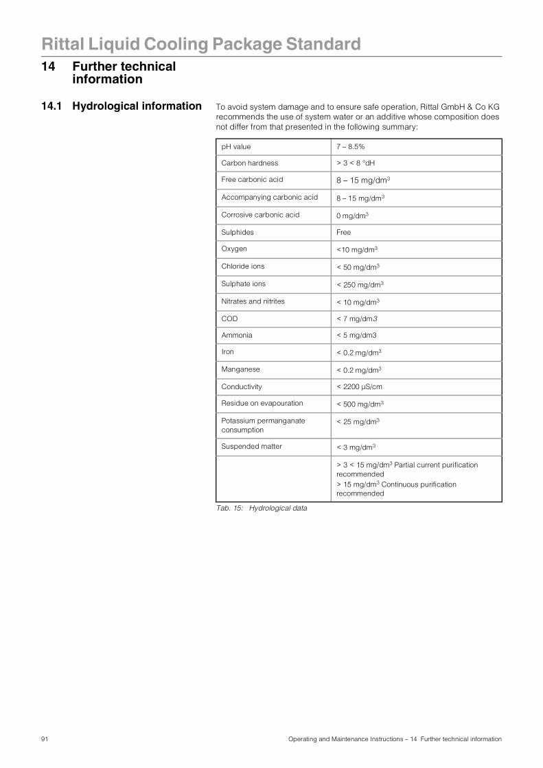
Rittal Liquid Cooling Package Standard
14 Further technicalinformation
14.1 Hydrological information To avoid system damage and to ensure safe operation, Rittal GmbH & Co KG recommends the use of system water or an additive whose composition does not differ from that presented in the following summary:
Tab. 15: Hydrological data
pH value 7 – 8.5%
Carbon hardness > 3 < 8 °dH
Free carbonic acid 8 – 15 mg/dm3
Accompanying carbonic acid 8 – 15 mg/dm3
Corrosive carbonic acid 0 mg/dm3
Sulphides Free
Oxygen <10 mg/dm3
Chloride ions < 50 mg/dm3
Sulphate ions < 250 mg/dm3
Nitrates and nitrites < 10 mg/dm3
COD < 7 mg/dm3
Ammonia < 5 mg/dm3
Iron < 0.2 mg/dm3
Manganese < 0.2 mg/dm3
Conductivity < 2200 µS/cm
Residue on evapouration < 500 mg/dm3
Potassium permanganate consumption
< 25 mg/dm3
Suspended matter < 3 mg/dm3
> 3 < 15 mg/dm3 Partial current purification recommended> 15 mg/dm3 Continuous purification recommended
91 Operating and Maintenance Instructions – 14 Further technical information
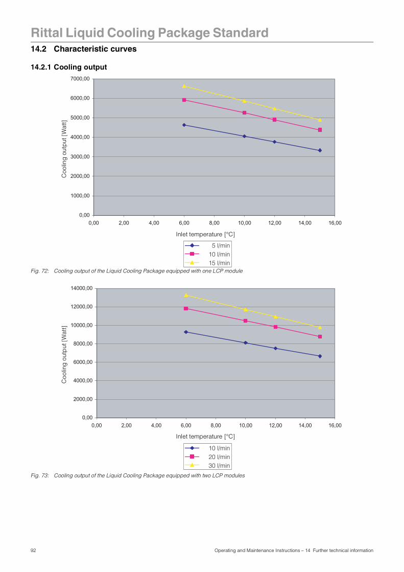
Rittal Liquid Cooling Package Standard
14.2 Characteristic curves14.2.1 Cooling output
Fig. 72: Cooling output of the Liquid Cooling Package equipped with one LCP module
Fig. 73: Cooling output of the Liquid Cooling Package equipped with two LCP modules
0,00
1000,00
2000,00
3000,00
4000,00
5000,00
6000,00
7000,00
0,00 2,00 4,00 6,00 8,00 10,00 12,00 14,00 16,00
5 l/min10 l/min15 l/min
Inlet temperature [°C]
Coo
ling
out
put
[Wat
t]
0,00
2000,00
4000,00
6000,00
8000,00
10000,00
12000,00
14000,00
0,00 2,00 4,00 6,00 8,00 10,00 12,00 14,00 16,00
10 l/min20 l/min30 l/min
Inlet temperature [°C]
Coo
ling
out
put
[Wat
t]
92 Operating and Maintenance Instructions – 14 Further technical information
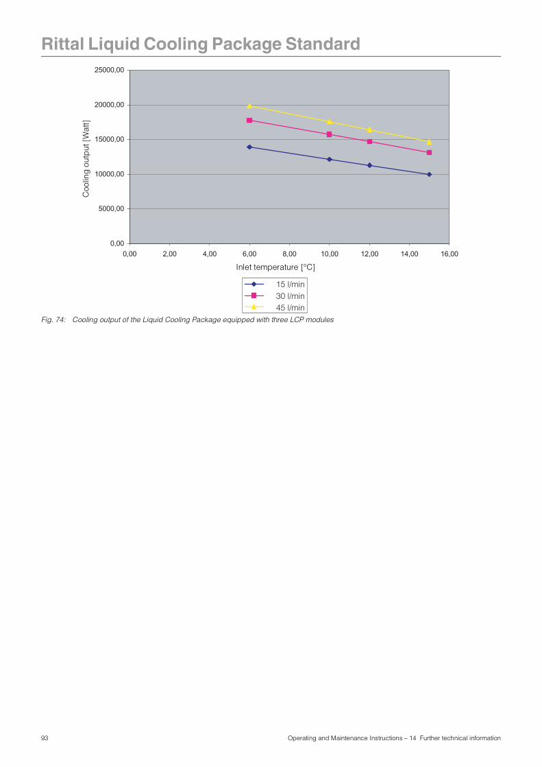
Rittal Liquid Cooling Package Standard
Fig. 74: Cooling output of the Liquid Cooling Package equipped with three LCP modules
0,00
5000,00
10000,00
15000,00
20000,00
25000,00
0,00 2,00 4,00 6,00 8,00 10,00 12,00 14,00 16,00
15 l/min30 l/min45 l/min
Inlet temperature [°C]
Coo
ling
out
put
[W
att]
93 Operating and Maintenance Instructions – 14 Further technical information
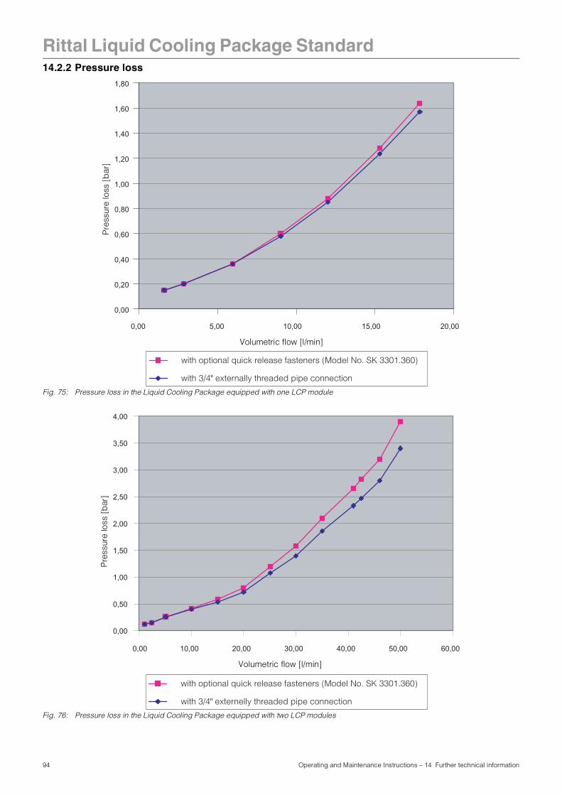
Rittal Liquid Cooling Package Standard
14.2.2 Pressure lossFig. 75: Pressure loss in the Liquid Cooling Package equipped with one LCP module
Fig. 76: Pressure loss in the Liquid Cooling Package equipped with two LCP modules
0,00
0,20
0,40
0,60
0,80
1,00
1,20
1,40
1,60
1,80
0,00 5,00 10,00 15,00 20,00
with 3/4" externally threaded pipe connection
with optional quick release fasteners (Model No. SK 3301.360)
Volumetric flow [l/min]
Pre
ssur
e lo
ss [
bar
]
0,00
0,50
1,00
1,50
2,00
2,50
3,00
3,50
4,00
0,00 10,00 20,00 30,00 40,00 50,00 60,00
with 3/4" externelly threaded pipe connection
with optional quick release fasteners (Model No. SK 3301.360)
Volumetric flow [l/min]
Pre
ssur
e lo
ss [
bar
]
94 Operating and Maintenance Instructions – 14 Further technical information
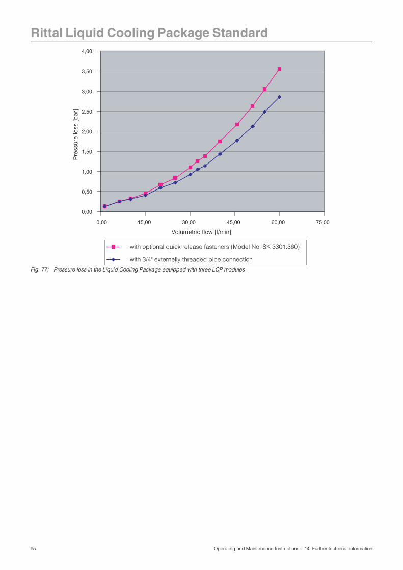
Rittal Liquid Cooling Package Standard
Fig. 77: Pressure loss in the Liquid Cooling Package equipped with three LCP modules
0,00
0,50
1,00
1,50
2,00
2,50
3,00
3,50
4,00
0,00 15,00 30,00 45,00 60,00 75,00
with 3/4" externelly threaded pipe connection
with optional quick release fasteners (Model No. SK 3301.360)
Volumetric flow [l/min]
Pre
ssur
e lo
ss [
bar
]
95 Operating and Maintenance Instructions – 14 Further technical information
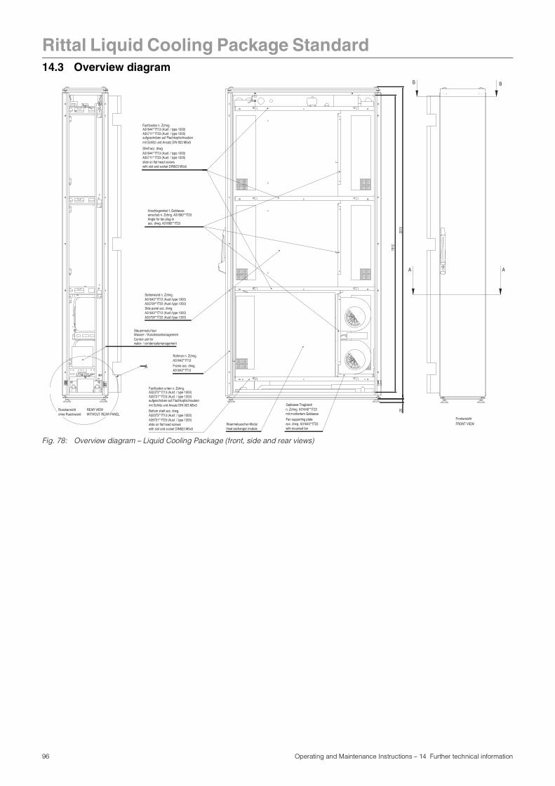
Rittal Liquid Cooling Package Standard
14.3 Overview diagramFig. 78: Overview diagram – Liquid Cooling Package (front, side and rear views)
Waermetauscher-Modul
Shelf acc. drwg.
slide on flat head screws
Anschlagwinkel f. Geblaese-einschub n. Zchng. A31660**IT23
Side panel acc. drwg.A31643**IT12 (Ausf./type 1000)
Frame acc. drwg.A31642**IT12
Steuermodul fuerWasser- / Kondensatmanagement
Fan supporting plate acc. drwg. A31645**IT23with mounted fan
water- / condensatemanagementControl unit for
Heat exchanger module
mit Schlitz und Ansatz DIN 923 M5x5aufgeschoben auf Flachkopfschrauben
A31644**IT13 (Ausf. / type 1000)Fachboden n. Zchng.
A35711**IT23 (Ausf. / type 1200)
A35711**IT23 (Ausf. / type 1200)A31644**IT13 (Ausf. / type 1000)
with slot and socket DIN923 M5x5
acc. drwg. A31660**IT23Angle for fan plug-in
A31643**IT12 (Ausf./type 1000)Seitenwand n. Zchng.
A35709**IT22 (Ausf./type 1200)
A35709**IT22 (Ausf./type 1200)
A31642**IT12Rahmen n. Zchng.
with slot and socket DIN923 M5x5
A35721**IT23 (Ausf. / type 1200)
A35721**IT23 (Ausf. / type 1200)
Fachboden unten n. Zchng.A32373**IT13 (Ausf. / type 1000)
aufgeschoben auf Flachkopfschraubenmit Schlitz und Ansatz DIN 923 M5x5
slide on flat head screws
Bottom shelf acc. drwg.A32373**IT13 (Ausf. / type 1000) mit montiertem Geblaese
n. Zchng. A31645**IT23Geblaese-Tragblech
A
Frontansicht
Rueckansicht ohne Rueckwand
FRONT VIEW
WITHOUT REAR PANELREAR VIEW 20
2010
1912
B B
A A
96 Operating and Maintenance Instructions – 14 Further technical information
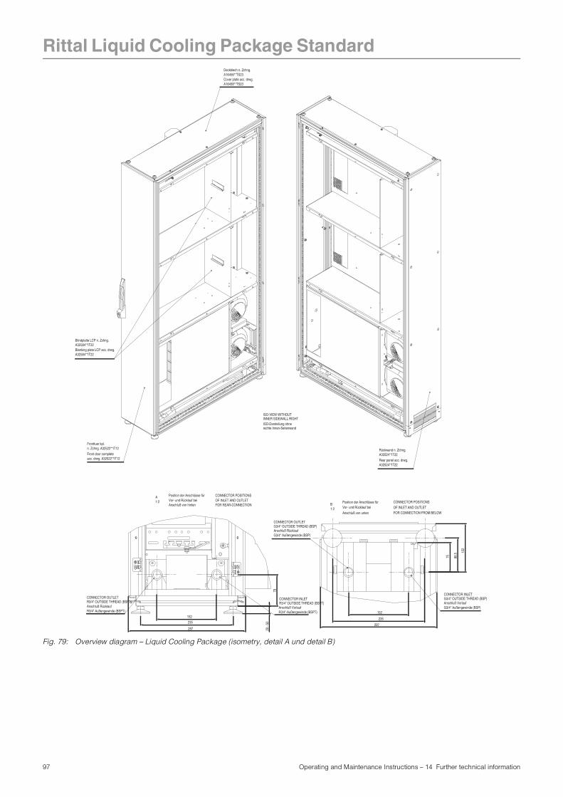
Rittal Liquid Cooling Package Standard
Fig. 79: Overview diagram – Liquid Cooling Package (isometry, detail A und detail B)
Cover plate acc. drwg.A16458**TS23
Rear panel acc. drwg. A32524**IT22
Front door completeacc. drwg. A32522**IT12
n. Zchng. A32522**IT12Fronttuer kpl.
A16458**TS23Deckblech n. Zchng.
A32524**IT22Rückwand n. Zchng.
Blindplatte LCP n. Zchng. A32584**IT22
A32584**IT22Blanking plate LCP acc. drwg.
R3/4"-Außengewinde (BSPT)Anschluß Vorlauf
G3/4" Außengewinde (BSP)Anschluß Rücklauf
1:2A
1:2BAnschluß von hinten
Vor- und Rücklauf beiPosition der Anschlüsse für
Anschluß von unten
Vor- und Rücklauf beiPosition der Anschlüsse für
G3/4" OUTSIDE THREAD (BSP)CONNECTOR OUTLET
CONNECTOR INLETG3/4" OUTSIDE THREAD (BSP)
FOR REAR-CONNECTIONOF INLET AND OUTLETCONNECTOR POSITIONS
CONNECTOR POSITIONS
OF INLET AND OUTLETFOR CONNECTION FROM BELOW
R3/4" OUTSIDE THREAD (BSPT)CONNECTOR INLETCONNECTOR OUTLET
R3/4" OUTSIDE THREAD (BSPT)Anschluß RücklaufR3/4" Außengewinde (BSPT)
ISO-Darstellung ohnerechte Innen-Seitenwand
INNER SIDEWALL RIGHTISO-VIEW WITHOUT
Anschluß VorlaufG3/4" Außengewinde (BSP)
297
235
152
122
86.5
75
235
152
20 -
50
79
297
97 Operating and Maintenance Instructions – 14 Further technical information
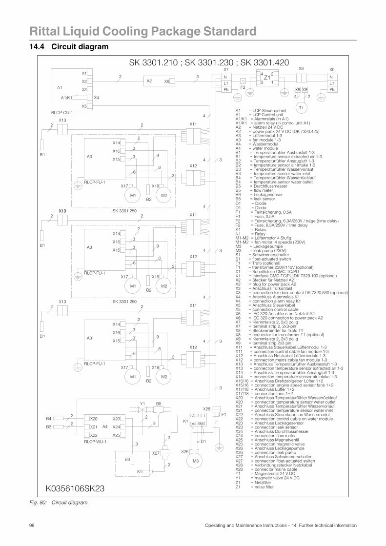
Rittal Liquid Cooling Package Standard
14.4 Circuit diagramFig. 80: Circuit diagram
A1 = LCP-Steuereinheit
A2 = Netzteil 24 V DC
A3 = Lüftermodul 1-3
A4 = Wassermodul
B1 = Temperaturfühler Ausblasluft 1-3
B2 = Temperaturfühler Ansaugluft 1-3
B3 = Temperaturfühler Wasservorlauf
B4 = Temperaturfühler Wasserrücklauf
B5 = Durchflussmesser
B6 = Leckagesensor
A1/K1 = Alarmrelais (in A1)
M1-M2 = Lüftermotor 4 Stufig
M3 = Leckagepumpe
S1 = Schwimmerschalter
T1 = Trafo (optional)
X1 = Schnittstelle CMC-TC/PU
X2 = Stecker für Netzteil A2
X3 = Anschluss Türkontakt
X4 = Anschluss Alarmrelais K1
X5 = Anschluss Steuerkabel
X6 = IEC 320 Anschluss an Netzteil A2
X7 = Klemmleiste 2, 2x3 polig
X8 = Steckverbinder für Trafo T1
X9 = Klemmleiste 2, 2x3 polig
X11 = Anschluss Steuerkabel Lüftermodul 1-3
X12 = Anschluss Netzkabel Lüftermodule 1-3
X13 = Anschluss Temperaturfühler Ausblassluft 1-3
X14 = Anschluss Temperaturfühler Ansaugluft 1-3
X15/16 = Anschluss Drehzahlgeber Lüfter 1+2
X17/18 = Anschluss Lüfter 1+2
X21 = Anschluss Temperaturfühler Wasservorlauf
X20 = Anschluss Temperaturfühler Wasserrücklauf
X22 = Anschluss Steuerkabel an Wassermodul
X23 = Anschluss Leckagesensor
X24 = Anschluss Durchflussmesser
X25 = Anschluss Magnetventil
X26 = Anschluss Leckagepumpe
X27 = Anschluss Schwimmerschalter
X28 = Verbindungsstecker Netzkabel
Y1 = Magnetventil 24 V DC
SK 3301.210 ; SK 3301.230 ; SK 3301.420
Z1 = Netzfilter
K1 = Relais
K0356106SK23
F1 = Feinsicherung, 0,5A
D1 = Diode
F2 = Feinsicherung, 6,3A/250V / träge (time delay)
T1
A1
X1
X2
X3
A1/K1
X5
X4
X6A22 3
X7
NL1PE
X9
NL1PE
X8
22
2 X11
4
2X13
34A3
2X13
B1
M1
X11
M2B2
X12
9
4
X14
X16
X15
X17 X18
2
SK 3301.250
2
3
3
3
66
X8 X8
2
13
4Z1
RLCP-FU-1
RLCP-CU-1
F2
34
2X13
B1
M1
X11
M2B2
X12
9
4
X23
A4 X24
X25
M3
X26X27
S1
3
X20
X21
X22
B42
B32
3
B62
Y1
2
3
B5
X14
X16
X15
X17 X18
X28F1
2
34B1
M1 M2B2
X12
9
X14
X16
X15
X17 X18
SK 3301.250
2
2
3
3
3
66
3
3
3
66
A3
A3
K1A2 9 6
D1RLCP-WU-1
RLCP-FU-1
RLCP-FU-1
2
A1
X13
A1 = LCP Control unit
A2 = power pack 24 V DC (DK 7320.425)
A3 = fan module 1-3
A4 = water module
B1 = temperature sensor extracted air 1-3
B2 = temperature sensor air intake 1-3
B3 = temperature sensor water inlet
B4 = temperature sensor water outlet
B5 = flow meter
B6 = leak sensor
A1/K1 = alarm relay (in control unit A1)
M1-M2 = fan motor, 4 speeds (230V)
M3 = leak pump (230V)
S1 = float-actuated switch
T1 = transformer 230V/115V (optional)
X1 = interface CMC-TC/PU DK 7320.100 (optional)
X2 = plug for power pack A2
X3 = connection for door contact DK 7320.530 (optional)
X4 = connection alarm relay K1
X5 = connection control cable
X6 = IEC 320 connection to power pack A2
X7 = terminal strip 2, 2x3-pin
X8 = connector for transformer T1 (optional)
X9 = terminal strip 2x3 pin
X11 = connection control cable fan module 1-3
X12 = connection mains cable fan module 1-3
X13 = connection temperature sensor extracted air 1-3
X14 = connection temperature sensor air intake 1-3
X15/16 = connection engine speed sensor fans 1+2
X17/18 = connection fans 1+2
X20 = connection temperature sensor water outlet
X21 = connection temperature sensor water inlet
X22 = connection control cable on water module
X23 = connection leak sensor
X24 = connection flow meter
X25 = connection magnetic valve
X26 = connection leak pump
X27 = connection float-actuated switch
X28 = connector mains cable
Y1 = magnetic valve 24 V DC
Z1 = noise filter
K1 = Relay
F1 = Fuse, 0.5A
D1 = Diode
F2 = Fuse, 6.3A/250V / time delay
98 Operating and Maintenance Instructions – 14 Further technical information
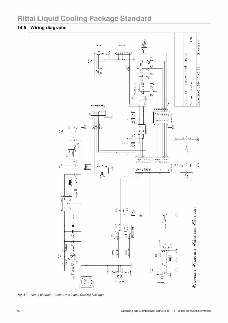
Rittal Liquid Cooling Package Standard
14.5 Wiring diagramsFig. 81: Wiring diagram – control unit Liquid Cooling Package
99 Operating and Maintenance Instructions – 14 Further technical information
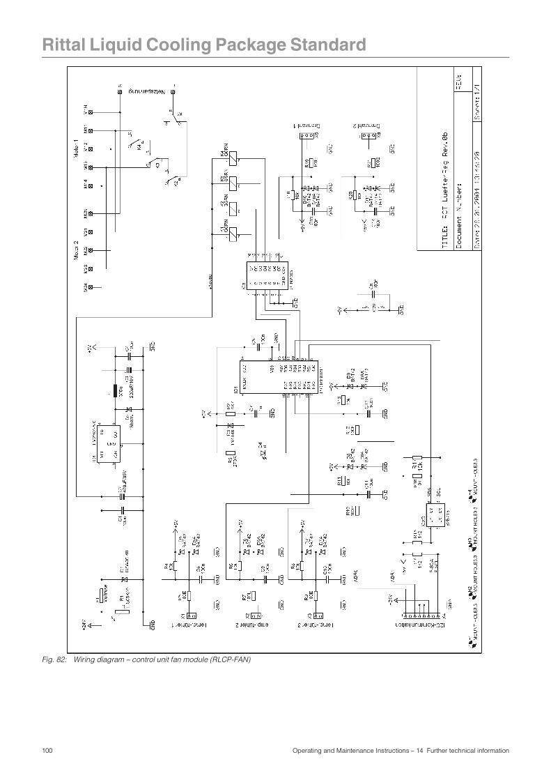
Rittal Liquid Cooling Package Standard
Fig. 82: Wiring diagram – control unit fan module (RLCP-FAN)
100 Operating and Maintenance Instructions – 14 Further technical information
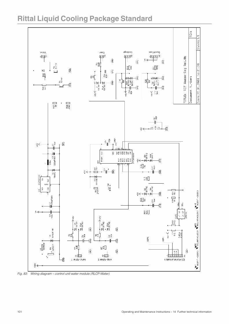
Rittal Liquid Cooling Package Standard
Fig. 83: Wiring diagram – control unit water module (RLCP-Water)
101 Operating and Maintenance Instructions – 14 Further technical information
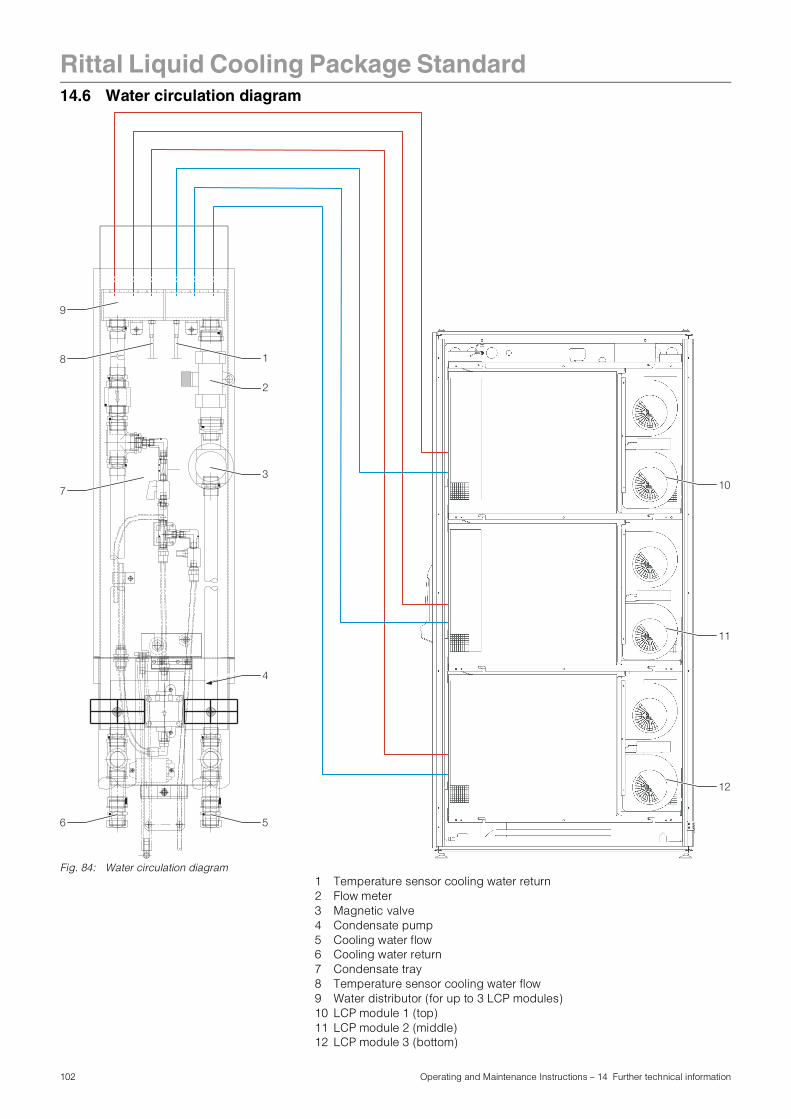
Rittal Liquid Cooling Package Standard
14.6 Water circulation diagramFig. 84: Water circulation diagram1 Temperature sensor cooling water return2 Flow meter3 Magnetic valve4 Condensate pump5 Cooling water flow6 Cooling water return7 Condensate tray8 Temperature sensor cooling water flow9 Water distributor (for up to 3 LCP modules)10 LCP module 1 (top)11 LCP module 2 (middle)12 LCP module 3 (bottom)
3/4"3/4"A
--A
--
1
3/4"
3/4"
A--
A--
22x322x3
22x322x3
22x3
22x3
ven
tive
nti
3/4"
-3/
4"-
3
3
22x322x3
1
1
RI
1
1
1 1
22x3
22x3
22x3
22x3
3/4"
-3/
4"-
3/4"-3/4" B3/4"-3/4" B
ä-Nr. 3526
-Nr. 3526
3/4"
-3/
4"-
3/4"-3/4" B3/4"-3/4" B
ä-Nr. 3526
-Nr. 3526
2
1
3
5
4
10
11
12
6
7
8
9
102 Operating and Maintenance Instructions – 14 Further technical information
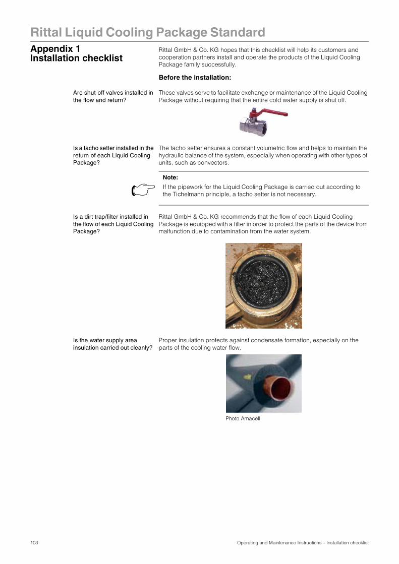
Rittal Liquid Cooling Package Standard
Appendix 1Installation checklistRittal GmbH & Co. KG hopes that this checklist will help its customers and cooperation partners install and operate the products of the Liquid Cooling Package family successfully.
Before the installation:
Are shut-off valves installed in the flow and return?
These valves serve to facilitate exchange or maintenance of the Liquid Cooling Package without requiring that the entire cold water supply is shut off.
Is a tacho setter installed in the return of each Liquid Cooling Package?
The tacho setter ensures a constant volumetric flow and helps to maintain the hydraulic balance of the system, especially when operating with other types of units, such as convectors.
Is a dirt trap/filter installed in the flow of each Liquid Cooling Package?
Rittal GmbH & Co. KG recommends that the flow of each Liquid Cooling Package is equipped with a filter in order to protect the parts of the device from malfunction due to contamination from the water system.
Is the water supply area insulation carried out cleanly?
Proper insulation protects against condensate formation, especially on the parts of the cooling water flow.
Note:
If the pipework for the Liquid Cooling Package is carried out according to the Tichelmann principle, a tacho setter is not necessary.
Photo Amacell
103 Operating and Maintenance Instructions – Installation checklist
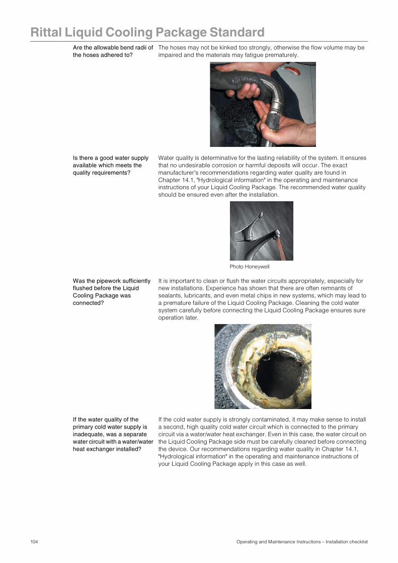
Rittal Liquid Cooling Package Standard
Are the allowable bend radii of the hoses adhered to?The hoses may not be kinked too strongly, otherwise the flow volume may be impaired and the materials may fatigue prematurely.
Is there a good water supply available which meets the quality requirements?
Water quality is determinative for the lasting reliability of the system. It ensures that no undesirable corrosion or harmful deposits will occur. The exact manufacturer's recommendations regarding water quality are found in Chapter 14.1, "Hydrological information" in the operating and maintenance instructions of your Liquid Cooling Package. The recommended water quality should be ensured even after the installation.
Was the pipework sufficiently flushed before the Liquid Cooling Package was connected?
It is important to clean or flush the water circuits appropriately, especially for new installations. Experience has shown that there are often remnants of sealants, lubricants, and even metal chips in new systems, which may lead to a premature failure of the Liquid Cooling Package. Cleaning the cold water system carefully before connecting the Liquid Cooling Package ensures sure operation later.
If the water quality of the primary cold water supply is inadequate, was a separate water circuit with a water/water heat exchanger installed?
If the cold water supply is strongly contaminated, it may make sense to install a second, high quality cold water circuit which is connected to the primary circuit via a water/water heat exchanger. Even in this case, the water circuit on the Liquid Cooling Package side must be carefully cleaned before connecting the device. Our recommendations regarding water quality in Chapter 14.1, "Hydrological information" in the operating and maintenance instructions of your Liquid Cooling Package apply in this case as well.
Photo Honeywell
104 Operating and Maintenance Instructions – Installation checklist

Rittal Liquid Cooling Package Standard
Was the water prepared/treated with the appropriate additives?In addition to our recommendations regarding water quality, we recommend that the water be enriched with corrosion inhibitor and/or antifreeze. Also, a treatment to prevent algae and biofilms may be expedient in some cases.
Are unused height units in the bayed server enclosures sealed through vertical blanking plates, and are the side vertical foam strips installed?
So that there are no undesired air short circuits and circulation patterns inside the server enclosure, all unused height units of the 482.6 mm (19") level should be closed off with blanking plates. Thus, the air will only enter the rear side of the server enclosure through the server itself, where it is drawn off by the Liquid Cooling Package. The blanking plates are available in various heights, e.g. Model No. SK 1931.200 for one height unit. The vertical foam sealing strips, which are installed on the side in the server enclosure, ensure that the cooled air does not flow on the sides, past the 482.6 mm (19") level. Sealing strips are available for 2 applications and 2 enclosure widths. The respective model numbers are found in Chapter 13, "Accessories" in the operating and maintenance instructions of your Liquid Cooling Package
Are all electrical, water, and power connections correctly made?
Before water is admitted, thus, ideally before the ball valves are opened, be sure to check that all connections are properly made. Pay special attention to check that all quick release fasteners are fully snapped into place.
Is the TS/PS server enclosure equipped with the appropriate door?
Both the Liquid Cooling Package Standard and the Liquid Cooling Package Plus function with a sealed air circuit. Thus, the cooled server enclosure must largely be hermetically sealed and equipped with unperforated steel or glass doors on the front and rear sides.
Exception when using the Liquid Cooling Package Extend:The front/front door of the server enclosure must, in this case, be fully air permeable.
After admitting cold water:
Are all parts and connections water tight?
Please check to be sure that all parts and connections which carry water are water tight. The Liquid Cooling Package is subject to an individual, comprehensive factory test, which also includes checking for leaks. This additional check serves to locate problems, such as possible transport damage, and to prevent greater damage.
Is the air bled from all modules/heat exchangers built into the Liquid Cooling Package?
It is recommended that the air be bled from the Liquid Cooling Package and its modules, especially when the Liquid Cooling Package forms the highest point of the cold water cycle. A vent valve (Model No. SK 3301.400) is available to bleed the air from the modularly built Liquid Cooling Package (Model No. SK 3301.230 and 3301.210). Liquid Cooling Package Plus and Liquid Cooling Package Extend may be bled, following the operating instructions, by their own built-in valves.
Photo Clariant
105 Operating and Maintenance Instructions – Installation checklist
Rittal Liquid Cooling Package Standard
After installation:We recommend that the following selected parameters be gathered and documented within a short time after installation.
- Inlet temperature
- Return temperature
- Volumetric flow with opened magnetic valve
Please feel free to contact Rittal if you have further questions or problems:
For malfunctions and repairs
Rittal Service Department
Tel.: +49 (0) 27 72/50 5-18 55E-mail: [email protected]
Note:
Documenting these parameters helps with error analysis if, during operation, malfunctions occur.
106 Operating and Maintenance Instructions – Installation checklist
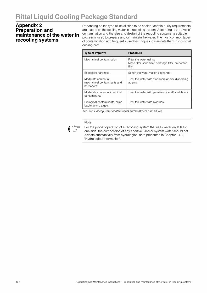
107 Operating and Maintenance Instructions – Preparation and maintenance of the water in recooling systems
Rittal Liquid Cooling Package StandardAppendix 2Preparation and maintenance of the water in recooling systems
Depending on the type of installation to be cooled, certain purity requirements are placed on the cooling water in a recooling system. According to the level of contamination and the size and design of the recooling systems, a suitable process is used to prepare and/or maintain the water. The most common types of contamination and frequently used techniques to eliminate them in industrial cooling are:
Tab. 16: Cooling water contaminants and treatment procedures
Type of impurity Procedure
Mechanical contamination Filter the water using:Mesh filter, sand filter, cartridge filter, precoated filter
Excessive hardness Soften the water via ion exchange
Moderate content of mechanical contaminants and hardeners
Treat the water with stabilisers and/or dispersing agents
Moderate content of chemical contaminants
Treat the water with passivators and/or inhibitors
Biological contaminants, slime bacteria and algae
Treat the water with biocides
Note:
For the proper operation of a recooling system that uses water on at least one side, the composition of any additive used or system water should not deviate substantially from hydrological data presented in Chapter 14.1, "Hydrological information".