Embed Size (px)
Citation preview

AW3000
RISE ABOVE
AW3000ACCIONA Windpower has seen explosive growth of orders for its AW3000 platform.
This success is due to a track record of reliability and product innovation coming from
one of the most experienced wind energy companies in the world. The latest evolution
is the AW132/3000 for low-wind sites, which delivers the lowest cost of energy in
this segment. Partner with ACCIONA Windpower to make your projects rise above
the competition.
OPTIMIZED PERFORMANCE FOR ALL SITES•Fullsuiteofrotoroptionscoveringallwindconditions,includingtheAW132/3000forlow-windsites
•Steelandconcretetoweroptionswithhubheightsfrom84to137.5meters
•Provenandbankabledesignsincludingdouble-bearingsupportonmainshaft,glassfiberandepoxybladesandDFIGelectricalgeneration
BUILT BY OPERATORS FOR OPERATORS•BasedonascaleddesignofoursuccessfulAW1500,theAW3000providesmoreenergycaptureperwindturbinelocation
•Ourtrackrecordoffleetwindturbineperformanceincludesglobalaverageavailabilityover98%andextremelylowfailureratesofmajorcomponents
COMPATIBILITY & CONTROL•Zerovoltageride-throughbeyondcurrentregulatoryrequirements,inadditiontogridintegrationandreactivepowersolutionstoallowformaximumcontrolforstringentgridcodes
•Controlsoftwarethatallowsintelligentautomaticmonitoringandoperation
SAFETY•Hydraulicpitchcontrolforsafeandreliablebladepitchinginallwindenvironments
•Two-personlift;hubaccessfrominsidethenacelle;andspacious,ergonomicnacelledesignallowforoperationalefficiency
12 KV VERSUS 690 V•Thisconfiguration,proveninourwindturbines,canremovethestep-uptransformerfromtheequationandisidealforprojectsthatareincloseproximitytothesubstation
•Theresultissignificantsavingsoverthelifeoftheproject
•Upto50%savingsincollectionsystemcosts
•Averageof1%greaterenergyproductionsduetotheavoidanceoftransformerelectricallosses
•Avoidanceofmaintenanceandpotentialfailuresoftransformers
AW3000DESIGNADVANTAGES
5
6
12 4
87
3
AW100/3000 AW
116/3000 AW125/3000 AW
132/3000
1 ) Double bearing-supported main shaft 2 ) Robust gearbox with HALT completed 3 ) 6 pole DFIG 12 kV generator 4 ) Elastic coupling 5 ) Cast hub with access from nacelle
6 ) Blades with structural shell design and proven materials including glass fiber and epoxy resin 7 ) Steel and concrete tower options from 84m to 137.5m hub heights 8 ) Yaw bearing and caliper brakes

The technical data included in this brochure may be subject to revision without prior notice. The technical data included in this brochure is not contractually binding.
AW3000TECHNICAL SPECIFICATIONS
MODEL AW100/3000 AW 116/3000 AW 125/3000 AW 132/3000
Rotor diameter 100 m 116 m 125 m 132 m
Wind class IEC la IEC lla IEC IIb/IIIa IEC IIIb
Turbine suitability High wind sites Medium wind sites Medium wind sites Low wind sites with higher turbulence with low turbulence with low turbulence intensity intensity intensity
OPERATING DATA
Cut-in wind speed 4 m/s 3.5 m/s 3.5 m/s 3 m/s
Cut-out wind speed 25 m/s 25 m/s 25 m/s 25 m/s
Cold Weather Operational -30ºC to + 40ºC Temperature range (Optional)
Power factor range +/- 0.93 (1,200 kVA) dynamic between +/- 5% p.u. voltage
Zero voltage ride through Meets or exceeds global requirements
ROTOR
Swept area 7,854 m² 10,568 m² 12,305 m² 13,720 m²
Power regulation Independent pitch regulated with variable speed
DRIVE TRAIN
Gearbox 3 stages: 2 planetary, 1 parallel (helical)
Bearings Double spherical roller bearings
Lubrication Pressure and splash with oil cooler/oil filter
PITCH SYSTEM
Actuation Hydraulic cylinders
Failsafes Blade-independent piston accumulators on hub
YAW SYSTEM
Type Four-point ball bearing, external gear
Slewing ring External
Braking system Disk+callipers, plus electro-mechanical brake per motor drive
GENERATOR
Type 6 poles, double feeding
Frequency 50/60 Hz
Nominal voltage 12,000 V (able to eliminate step-up transformers depending on wind farm layout)
TOWER
Steel hub height - 92 87.5 84 options (m)
Steel tower number - 4 4 4 of sections
Concrete hub height 100 100, 120 100, 120, 137.5 120 options (m)
Concrete tower number 5 5, 6 5, 6, 7 6 of sections
NACELLE
Weight (tons) 111 t (without hub)
Dimensions 10.9 m (length) 4.09 m (width) 4.15 m (height)
Transportability Four options (split nacelle), and rail capable
LIFE AND HOIST CAPACITIES
Service lift capacity 250 kg
Onboard crane hoist lift capacity 500 kg
www.acciona-windpower.com [email protected]
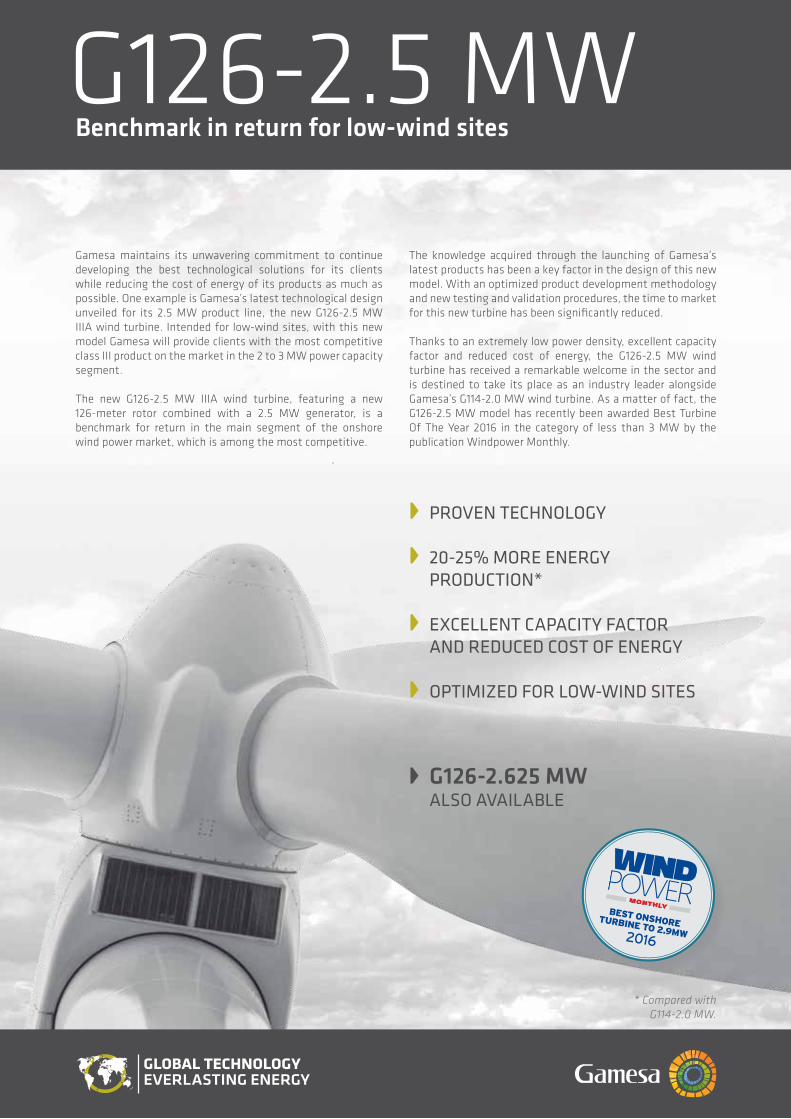
PROVEN TECHNOLOGY
20-25% MORE ENERGY PRODUCTION*
EXCELLENT CAPACITY FACTOR
AND REDUCED COsT OF ENERGY
OPTIMIZED FOR LOW-WIND sITEs
G126-2.625 MW ALsO AVAILABLE
* Compared with G114-2.0 MW.
Gamesa maintains its unwavering commitment to continue developing the best technological solutions for its clients while reducing the cost of energy of its products as much as possible. One example is Gamesa’s latest technological design unveiled for its 2.5 MW product line, the new G126-2.5 MW IIIA wind turbine. Intended for low-wind sites, with this new model Gamesa will provide clients with the most competitive class III product on the market in the 2 to 3 MW power capacity segment.
The new G126-2.5 MW IIIA wind turbine, featuring a new 126-meter rotor combined with a 2.5 MW generator, is a benchmark for return in the main segment of the onshore wind power market, which is among the most competitive.
The knowledge acquired through the launching of Gamesa’s latest products has been a key factor in the design of this new model. With an optimized product development methodology and new testing and validation procedures, the time to market for this new turbine has been significantly reduced.
Thanks to an extremely low power density, excellent capacity factor and reduced cost of energy, the G126-2.5 MW wind turbine has received a remarkable welcome in the sector and is destined to take its place as an industry leader alongside Gamesa’s G114-2.0 MW wind turbine. As a matter of fact, the G126-2.5 MW model has recently been awarded Best Turbine Of The Year 2016 in the category of less than 3 MW by the publication Windpower Monthly.
G126-2.5 MWBenchmark in return for low-wind sites

NEW MODEL G126-2.5 MW IIIA
Gamesa harnessed the experience acquired through the installation of 26 GW of its high performance 2.0 MW platform to develop this new model, capable of generating even more power at low-wind sites while remaining as competitive as the existing models with smaller rotor. The company’s most recently developed turbines thus emerge through this approach: G114-2.0 MW IIA/IIIA, G114-2.5 MW IIA, and now G126-2.5 MW IIIA.
Following the evolutionary model of the 2.5 platform, and minimizing the risk associated with new technologies, the G126-2.5 MW is equipped with a 62 meter blade based on the 56-meter variant already delivering maximum production at lower noise and comprehensively validated for G114 turbines. Based on the same principle, the electrical system incorporated in the G126 is common for all 2.5 MW models.
Boasting a 20% increase in power production compared to the G114-2.0 MW model, the G126-2.5 MW wind turbine rounds off Gamesa’s offering for Class III sites. With this new addition, Gamesa completes its 2.5 MW product portfolio, with three different rotors, tower heights from 68 to 137 meters, and environmental options enabling installation at even the most complex sites.
SPECIFICATIONS
General Details
Rated power Wind class Rotor diameter Swept area Power density Control Gearbox Generator Frequency
Blades
Length Airfoil
Towers
Height
G126-2.5 MW
2.5 MWIIIA126 m12,469 m2
200.50 W/m2
Pitch and variable speed3 stagesDoubly fed50Hz / 60 Hz
62 mGamesa
84, 102, 129, 137 m and site specific
G126-2.625 MW
2.625 MWIIIA126 m12,469 m2
210.52 W/m2
Pitch and variable speed3 stagesDoubly fed50Hz / 60 Hz
62 mGamesa
84, 102, 129, 137 m and site specific
Pow
er (k
W)
Wind speed (m/s)
G114-2.0 MW G126-2.5 MW
400
1 2 3 4 5 6 7 8 9 10 11 12 13 14 15 16 17 18 19 20 21 22 23 24 25
800
1200
1600
2000
2500
∆ A
EP
G12
6-2.
5 M
W v
s. G
114-
2.0
MW
Average wind speed (m/s)
0%
5%
10%
15%
25%
20%
30%
35%
6,0 6,5 7,0 7,5 8,0
In order to minimize the environmental impact, this document has been printed on paper made from 50% pure cellulose fiber (ECF), 40% selected pre-consumer recycled fiber, and 10% post-consumer deinked recycled fiber inks based exclusively on vegetable oils with a minimum volatile organic compound (VOC) content. Varnish based predominantly on natural and renewable raw materials.
The present document, its content, its annexes and/or amendments has been drawn up by Gamesa Corporación Tecnológica, S.A. for information purposes only and could be modified without prior notice. All the content of the Document is protected by intellectual and industrial property rights owned by Gamesa Corporación Tecnológica, S.A. The addressee shall not reproduce any of the information, neither totally nor partially.
Printed date: January 2017
C/ Ciudad de la Innovación, 9-1131621 sarriguren (spain)
Tel: +34 948 771 000Fax: +34 948 165 039
NOMINAL POWER INCREASE
G1142.0 MW
G1262.5 MW
SWEPT AREA INCREASE
+22%
AEP INCREASE
>20%
2.5
MW
G126
2.0
MW
G114
AUSTRALIALevel 39 , 385 Bourke Street Melbourne VIC 3000
BRAZILEldorado Business TowerAv. das Nações Unidas, 8.501 l 5º andar Pinheiros, São Paulo - SP Tel: +55 11 3096 4444
CHILEPresidente Riesco 5335 – Piso 9Las Condes - Santiago Tel: +56 (2) 2714 3872
CHINA23/F, Tower 1, Beijing Prosper Center No. 5Guanghua Road, Chaoyang District,Beijing 100020Tel: +86 10 5789 0899Fax: +86 10 5761 1996
EGYPT3, Rd 218 Degla11431 Maadi, CairoTel: +20 225 211 048Fax: +20 225 211 282
FRANCE97 Allée Borodine - Cedre 369800 Saint PriestTel: +33 (0) 4 72 79 49 39
GERMANYRöntgenstraße 2822335 Hamburg FuhlsbüttelTel: +49 40 537 998 440
GREECE9 Adrianiou str,11525 Neo Psychiko, AthensTel: +30 21067 53300Fax: +30 21067 53305
HONG KONGAsia Pacific OceaniaCentral Plaza, 35th Floor, 18, Harbour RoadHong Kong SARTel: +852 2593 1140
INDIAThe Futura IT Park, B-Block, 8th Floor334, Rajiv Gandhi SalaiSholinganallur, Chennai - 600 119Tel: +91 44 3924 [email protected]
ITALYVia Ostiense 131/LCorpo C1 – 9° piano00154 RomeTel: +39 06 5750531Fax: +39 06 5754735
JAPANTOC Minatomirai Bldg. 10F,1-1-7 Sakuragi-cho, Naka-ku,Yokohama-shi, Kanagawa 231-0062T: +81 80 3465 6861
MEXICOTorre MayorPaseo de la Reforma 505, piso 37Col. CuauhtémocC.P. 06500, Ciudad de MéxicoTel: +52 55 50179700
PHILIPPINES22th Floor, The Enterprise Center Tower I1226 Ayala Avenue Makati City PhilippinesTel: +63 917 820 4414
POLANDUl. Galaktyczna 30A80-299 GdanskTel: +48 58 766 62 62Fax: +48 58 766 62 [email protected]
ROMANIA169A Calea Floreasca Street,Building A, 4th Floor, Office no 2069, Sector 1014459 BucarestTel: +40 318 21 24Fax: +40 318 60 21 00
SRI LANKA#51/1, Colombo Road,Kurana, KatunayakeTel: +94 31 2235890
SWEDEN, FINLAND, NORWAYBibilotekstorget 8171 45 Solna (Sweden)Tel: +46 (0) 8 510 668 10
THAILANDSathom Square, 98 North Sathom Road37/F Sathom Square Silom, BangkokBangkok 10500
TURKEYAstoria, Buyukdere Cad. No. 127, Kule A, Kat 10Esentepe, Istambul 34394Tel: +90 212 340 76 00
UNITED KINGDOMBraidhurst HouseFinch Way, Strathclyde Business Park,Bellshill ML4 3PETel: +44 1698 572 860
UNITED STATES1150 Northbrook DriveTrevose, PA 19053Tel: +1 215 710 3100Fax: +1 267 790 0453

G132-3.3 MWOptimum CoE for sites with medium winds
The BEST CoE in the 3.0-3.6 MW segment
New platform based on MATURE and PROVEN TECHNOLOGY
34% LARGER SWEPT AREA*
G132-3.465 MW ALSO AVAILABLE
One of the keys to Gamesa’s success is the constant development of new and advanced products adapted to customers’ needs in any type of site and with maximum profitability.
With this purpose in mind the new Gamesa 3.3 MW platform has been launched with its first model: the G132-3.3 MW wind turbine for Class II sites. A new generation of multi-megawatt turbines that reaches the market to become the best solution in terms of Cost of Energy in the 3.0-3.6 MW segment, one of the most competitive and demanding. This new platform, together with the current Gamesa 2.0 MW, Gamesa 2.5 MW and Gamesa 5.0 MW, makes the company product portfolio one of the most complete and versatile in the market and allows Gamesa to assure the best solution for customers’ projects.
Thanks to the operative experience accumulated by Gamesa throughout more than 20 years in the wind energy market, the G132-3.3 MW wind turbine enables the company to guarantee the highest levels of reliability. The use of mature and proven technology available in Gamesa’s current portfolio has resulted in the first G132-3.3 MW prototype installed in 2016.
* vs. G114-2.0 MW and G114-2.5 MW.

C/ Ciudad de la Innovación, 9-1131621 Sarriguren (Spain)
Tel: +34 948 771 000Fax: +34 948 165 039
New G132-3.3 Mw IIA wINd turbINe
The G132-3.3 MW IIA wind turbine is integrated in the portfolio of Gamesa with a clear objective: to complement the product offer for medium-wind sites in markets where the customers require solutions with nominal powers higher than 3 MW.
The G132-3.3 MW turbine improves on the production capacity of the models G114-2.0 MW and G114-2.5 MW, available for Class II sites, both boosting the nominal power up to 3.3 MW and increasing the rotor swept area by 34%, which makes it one of the most efficient and cost-effective solutions for medium-wind sites.
With a 64.5 m fiberglass blade, optimized for Class II sites and with airfoils that have already been thoroughly tested and validated in the G132-5.0 MW IIA wind turbine (first prototype installed in Alaiz -Spain- in the second quarter of 2015), the new model G132-3.3 MW guarantees maximum energy production and low noise emission levels, with maximum theoretical value for this turbine fixed at 105.7 dBA.
Gamesa incorporates proven technology into this model, such as the combination of a three-stage gearbox (two planetary stages and one parallel) and a doubly-fed induction generator, the same solution used in the Gamesa 2.0 MW platform, which has 26 GW installed worldwide.
The G132-3.3 MW wind turbine also has an extensive portfolio of towers with heights ranging from 84 m to 154 m, which enables it to comply with the different maximum blade tip height restrictions in certain markets.
SPeCIFICAtIONS
General Details
Rated power Wind class Rotor diameter Swept area Power densityControl Gearbox Generator Frequency
Blades
Length Airfoil
Towers
Height
G132-3.3 MW
3.3 MWIIA132 m13,685 m2
241.14 W/m2
Pitch and variable speed3 stagesDoubly fed50 Hz / 60 Hz
64.5 mGamesa
84, 97, 114, 134, 154 m and site specific
G132-3.465 MW
3.465 MWIIA132 m13,685 m2
253.20 W/m2
Pitch and variable speed3 stagesDoubly fed50 Hz / 60 Hz
64.5 mGamesa
84, 97, 114, 134, 154 m and site specific
NOMINAL POwer INCreASe
+34%
SwePt AreA INCreASe AeP INCreASe
3.3 Mw2.5 Mw
2.0 Mw
G114
G132
Pow
er (k
W)
Wind speed (m/s)
G114-2.0 MW G114-2.5 MW G132-3.3 MW
1 2 3 4 5 6 7 8 9 10 11 12 13 14 15 16 17 18 19 20 21 22 23 24 25
1500
2000
2500
3000
3500
∆ A
EP G
132-
3.3
MW
vs
. G11
4-2.
0 M
W &
G11
4-2.
5 M
W
Average wind speed (m/s)
0%
10%
20%
30%
50%
40%
60%
70%
7,0 7,5 8,0 8,5 9,0
G132-3.3 MW vs. G114-2.0 MW G132-3.3 MW vs. G114-2.5 MW
1000
500
In order to minimize the environmental impact, this document has been printed on paper made from 50% pure cellulose fiber (ECF), 40% selected pre-consumer recycled fiber, and 10% post-consumer deinked recycled fiber inks based exclusively on vegetable oils with a minimum volatile organic compound (VOC) content. Varnish based predominantly on natural and renewable raw materials.
The present document, its content, its annexes and/or amendments has been drawn up by Gamesa Corporación Tecnológica, S.A. for information purposes only and could be modified without prior notice. All the content of the Document is protected by intellectual and industrial property rights owned by Gamesa Corporación Tecnológica, S.A. The addressee shall not reproduce any of the information, neither totally nor partially.
Printed date: January 2017
AUSTRALIALevel 39 , 385 Bourke Street Melbourne VIC 3000
BRAZILEldorado Business TowerAv. das Nações Unidas, 8.501 l 5º andar Pinheiros, São Paulo - SP Tel: +55 11 3096 4444
CHILEPresidente Riesco 5335 – Piso 9Las Condes - Santiago Tel: +56 (2) 2714 3872
CHINA23/F, Tower 1, Beijing Prosper Center No. 5Guanghua Road, Chaoyang District,Beijing 100020Tel: +86 10 5789 0899Fax: +86 10 5761 1996
EGYPT3, Rd 218 Degla11431 Maadi, CairoTel: +20 225 211 048Fax: +20 225 211 282
FRANCE97 Allée Borodine - Cedre 369800 Saint PriestTel: +33 (0) 4 72 79 49 39
GERMANYRöntgenstraße 2822335 Hamburg FuhlsbüttelTel: +49 40 537 998 440
GREECE9 Adrianiou str,11525 Neo Psychiko, AthensTel: +30 21067 53300Fax: +30 21067 53305
HONG KONGAsia Pacific OceaniaCentral Plaza, 35th Floor, 18, Harbour RoadHong Kong SARTel: +852 2593 1140
INDIAThe Futura IT Park, B-Block, 8th Floor334, Rajiv Gandhi SalaiSholinganallur, Chennai - 600 119Tel: +91 44 3924 [email protected]
ITALYVia Ostiense 131/LCorpo C1 – 9° piano00154 RomeTel: +39 06 5750531Fax: +39 06 5754735
JAPANTOC Minatomirai Bldg. 10F,1-1-7 Sakuragi-cho, Naka-ku,Yokohama-shi, Kanagawa 231-0062T: +81 80 3465 6861
MEXICOTorre MayorPaseo de la Reforma 505, piso 37Col. CuauhtémocC.P. 06500, Ciudad de MéxicoTel: +52 55 50179700
PHILIPPINES22th Floor, The Enterprise Center Tower I1226 Ayala Avenue Makati City PhilippinesTel: +63 917 820 4414
POLANDUl. Galaktyczna 30A80-299 GdanskTel: +48 58 766 62 62Fax: +48 58 766 62 [email protected]
ROMANIA169A Calea Floreasca Street,Building A, 4th Floor, Office no 2069, Sector 1014459 BucarestTel: +40 318 21 24Fax: +40 318 60 21 00
SRI LANKA#51/1, Colombo Road,Kurana, KatunayakeTel: +94 31 2235890
SWEDEN, FINLAND, NORWAYBibilotekstorget 8171 45 Solna (Sweden)Tel: +46 (0) 8 510 668 10
THAILANDSathom Square, 98 North Sathom Road37/F Sathom Square Silom, BangkokBangkok 10500
TURKEYAstoria, Buyukdere Cad. No. 127, Kule A, Kat 10Esentepe, Istambul 34394Tel: +90 212 340 76 00
UNITED KINGDOMBraidhurst HouseFinch Way, Strathclyde Business Park,Bellshill ML4 3PETel: +44 1698 572 860
UNITED STATES1150 Northbrook DriveTrevose, PA 19053Tel: +1 215 710 3100Fax: +1 267 790 0453

GE Renewable Energy
www.ge.com/wind
GE’s 3 MW Platform POWERFUL AND EFFICIENT

BIG DATA
BRILLIANT
WIN
D POWER D
OMAIN
CONNECTED MACHINES
ROC
WindCONTROL ™
ANALYTICS
PowerUp™
PulsePoint™
Predix
™
WindSCADA
™
SOFTWARE CoE
SPEED
MONITORIN
G
CONTROLS
VALIDATION
YAW
PITCH
VORTEX
DIGITIZED WORKFLOW
TORQUE
DIGITA
L WIN
D FARM
INDUSTRIAL INTERNET
GE’S 3 MW PLATFORM
Since entering the wind industry in 2002,
GE Renewable Energy has invested more
than $2 billion in next-generation wind
turbine technology to provide more value
to customers—whether at the turbine,
plant or grid level. Through the use of
advanced analytics, GE Renewable Energy
is redefining the future of wind power,
delivering with proven performance,
availability and reliability. With the
integration of big data and the industrial
internet, we can help customers manage
the variability that comes with this resource
for smooth, predictable power. Our onshore
product portfolio includes wind turbines
with rated capacities from 1.6-3.8 MW
and flexible support services that range
from basic operations and maintenance
to farm- or fleet-level enhancements.
For more information visit our website:
www.ge.com/wind

POWERFUL AND EFFICIENT
GE’s 3 MW Platform Extending the capability of the Digital Wind Farm to our 3 MW machines, GE’s powerful and efficient
3.2–3.8 platform is adaptable to a full spectrum of wind regimes. The platform includes the 3.6-137, our
highest performing turbine for Class III winds.
GE has employed selected legacy components with proven performance for the 3 MW platform, helping
to ensure the consistent performance and reliability for which GE wind turbines are known. Turbine models
within the 3 MW platform share drivetrain and electrical system architecture, with both systems scaled
and upgraded for improved performance and greater energy production, as compared to previous models.
3
Parameters of the 3MW PlatformGE’s 3MW platform can be customized based on nameplate, rotor diameter and hub height.

GE’S 3.2–130GE’S 3 MW PLATFORM
Building Upon Proven Technology
Built from the maturity of its predecessors, the 3 MW platform increases the capacity factor, annual
energy production (AEP) and application space. Component enhancements to the 2.5 MW models have
resulted in a substantial performance increase, enabling the use of a 130- and 137- meter rotor on
the 3 MW series and a nameplate ranging from 3.2–3.8 MW. These enhancements include gearbox
and controls improvements, and a new aerodynamic structure enabling a greater blade length
(130–137 meter rotor). Crafted for high reliability, GE’s 3 MW platform offers excellent availability that is
comparable to the 2.5 MW series units operating in the field today.
Technical DescriptionGE’s 3 MW platform machines are three-blade, upwind, horizontal axis wind turbines with a rotor
diameter ranging from 130 to 137 meters. The turbine rotor and nacelle are mounted on top of a tubular
steel tower, with a range of hub height options that includes 85-, 110-, 131.4-, 134- and 164.5-meter
variants. The turbines use active yaw control to keep the blades pointed into the wind. The 3 MW
platform is engineered to operate at variable speeds and uses a doubly fed asynchronous generator
with a partial power converter system.
4
2010
3.2-1303.2-103
2015
2.75-120
2016 2017
3.6-1373.8-130
2014
2.5-120
2013
2.85-103
2011
2.75-103
2009
2.75-100
2006
2.5-100
2004
2.5-88
3.4-1303.4-137
3MW Platform
Model introduction in Europe

Specifications3 MW platform
• Standard and cold weather extreme options
• Standard tower corrosion protection: C2 internal and C3 external with internal and external
C4/C5 options available
• Rotational direction: Clockwise viewed from an upwind location
• Speed regulation: Electric drive pitch control with battery backup
• Aerodynamic brake: Full feathering of blade pitch
GE’s 3.2-130 IEC 2B/3A
• Up to 20% higher output than GE’s 2.5-120
• Improved load management system and more efficient drive train technology
• Same electrical system as 3.2-103 turbine
• Sound power level of 106 db(A), reduced noise modes available
• Tip heights include 150 m, 175 m, and 199 m rotor
GE’s 3.8-130 IEC2B
• Up to 30% higher output than GE’s 3.2-103
• Increased electrical rating of 3.4 MW combined with 130-meter rotor
• 106.5 dB(A) normal operation sound power level, reduced noise modes available
• Tip heights include 150 m, 175 m, 199 m, and 233 m
GE’s 3.6-137 IEC3B
• Up to 28% higher output than GE’s 2.75-120
• New blade for more efficient production in low wind conditions
• Sound power level of 106 db(A), reduced noise modes available
• Tip heights include 178.5 m, 199 m, and 223 m
POWERFUL AND EFFICIENT
5

Features and Benefits• Engineered to meet or exceed the 2.5 MW platform’s historic high availability
• Available grid-friendly options:
— Enhanced Reactive Power, Low & Zero Voltage Ride Thru, Power Factor Control, WindFreeReactive Power
• Wind Farm Control System; WindSCADA*
• Available in both 50 Hz and 60 Hz versions
Construction
Towers:
• Tubular steel sections provide a hub height of 85 m, 110 m, and 131 m
• Hybrid pre-cast concrete/tubular steel towers for multiple hub heights
• Logistic friendly tower for a hub height of 85 m, 110 m, and 131 m
Blades:
• 63.7-meter blades (130-meter rotor); 67.2-meter blades (137-meter rotor)
Drivetrain components:
• GE’s 3 MW platform uses an enhanced gearbox, main shaft with double bearings, and generator
with appropriate improvements to enable the 130- and 137-meter diameter rotor in medium and
lower wind speeds.
Enhanced Controls TechnologyThe 3 MW platform uses enhanced controls features:
• GE’s patented Advanced Loads Control reduces loads on turbine components by measuring
stresses and individually adjusting blade pitch.
• Controls were developed by GE Global Research to reduce extreme loads, including those near
rated wind speeds, to improve annual energy production (AEP).
Condition Monitoring SystemGE’s Condition Monitoring System (CMS) and SCADA Anomaly Detection Services, a complementary
suite of advanced condition monitoring solutions, proactively detects impending drive train and
whole-turbine issues, enabling increased availability and decreased maintenance expenses. Built
upon half a century of power generation drivetrain and data anomaly monitoring experience, this
service solution is now standard on GE’s 3 MW platform.
GE’S 3 MW PLATFORM
6

POWERFUL AND EFFICIENT
7

BIG DATA
BRILLIANT
WIN
D POWER D
OMAIN
CONNECTED MACHINES
ROC
WindCONTROL ™
ANALYTICS
PowerUp™
PulsePoint™
Predix
™
WindSCADA
™
SOFTWARE CoE
SPEED
MONITORIN
G
CONTROLS
VALIDATION
YAW
PITCH
VORTEX
DIGITIZED WORKFLOW
TORQUE
DIGITA
L WIN
D FARM
INDUSTRIAL INTERNET*Trademark of General Electric Company
Copyright © 2016 General Electric Company. All rights reserved.
GEA32208 (09/2016)
MAKING RENEWABLES THE ENERGY OF CHOICE FOR A CLEANER FUTUREwww.ge.com/wind

DELTA GENERATION PROVEN TECHNOLOGY – AT A NEW STAGE OF EVOLUTION
N100/3300N117/3000N131/3000

03 TECHNICAL DEVELOPMENT AT NORDEX Experiencekeepsusonestepahead 04 MATURE TECHNOLOGY Provenconceptsensureasecureinvestment
06 ECONOMIC EFFICIENCY Higheryieldsreducethecostofenergy 08 QUALITY AND RELIABILITY Afocusonhighavailability 10 SERVICE AND HSE FastandsafeturbineO&M
12 DELTA GENERATION IN THE FIELD Firstturbinesinstalledandcertified 14 SOLUTION FOR STRONG WIND Highyieldsinaroughclimate 16 SOLUTION FOR MODERATE WIND Economicalatawiderangeofsites
18 SOLUTION FOR LIGHT WIND Maximumefficiencyinthe3MWsegment
CONTENTS
02 | Delta Generation
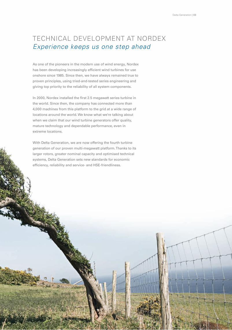
TECHNICAL DEVELOPMENT AT NORDEX Experiencekeepsusonestepahead
Asoneofthepioneersinthemodernuseofwindenergy,Nordex
hasbeendevelopingincreasinglyefficientwindturbinesforuse
onshoresince1985.Sincethen,wehavealwaysremainedtrueto
provenprinciples,usingtried-and-testedseriesengineeringand
givingtopprioritytothereliabilityofallsystemcomponents.
In2000,Nordexinstalledthefirst2.5megawattseriesturbinein
theworld.Sincethen,thecompanyhasconnectedmorethan
4,000machinesfromthisplatformtothegridatawiderangeof
locationsaroundtheworld.Weknowwhatwe’retalkingabout
whenweclaimthatourwindturbinegeneratorsofferquality,
maturetechnologyanddependableperformance,evenin
extremelocations.
WithDeltaGeneration,wearenowofferingthefourthturbine
generationofourprovenmulti-megawattplatform.Thankstoits
largerrotors,greaternominalcapacityandoptimisedtechnical
systems,DeltaGenerationsetsnewstandardsforeconomic
efficiency,reliabilityandservice-andHSE-friendliness.
Delta Generation | 03

MATURE TECHNOLOGY Provenconceptsensureasecureinvestment
The fourth generation of the Nordex multi-megawatt platform combines proven, dependable technology with targeted improvements for enhanced performance.
04 | Delta Generation
WiththenewDeltaGeneration,Nordexcustomersbenefitfrom
theknow-howwehavegatheredinthemulti-megawattrange
overmanyyears.Maturetechnicalsolutionsthathaveproven
theirworththousandsoftimesformasoundbasisforthe
newgeneration.
Continuity:Theelectricalsystem
EventhefirstNordexmulti-megawattturbinewasequipped
withadoublyfedasynchronousgeneratorandapartialcon-
verter.WithDeltaGeneration,wehavemaintainedthis
provenandhighlyeconomicalelectricalsystem.
Tried-and-testeddrivetrainconcept
Thedrivetrainsystemisbased
onamodulardrivetrainlayout
withathree-pointsuspension.
Wehaveusedthissystem
successfullyfromtheoutset.
Togetherwithourqualified
suppliers,weworkoncontin-
uouslyimprovingourdrivetrain
components.Thisdeliversthe
outputrequiredwhilemaintaining
availabilityatahighlevel.
Provenrotorbladedesigns
Theturbinesofthenewgenerationuse
provenaerodynamicdesignsfortherotor
diametersof100and117metres.Nordex
developedtheNR50,NR58.5andNR65.5
bladesin-house.Thisallowedustorealisean
optimalconceptfortheoverallturbinesystem.
Theefficientrotorbladesmatchtherespectiveturbine
technologyperfectly.
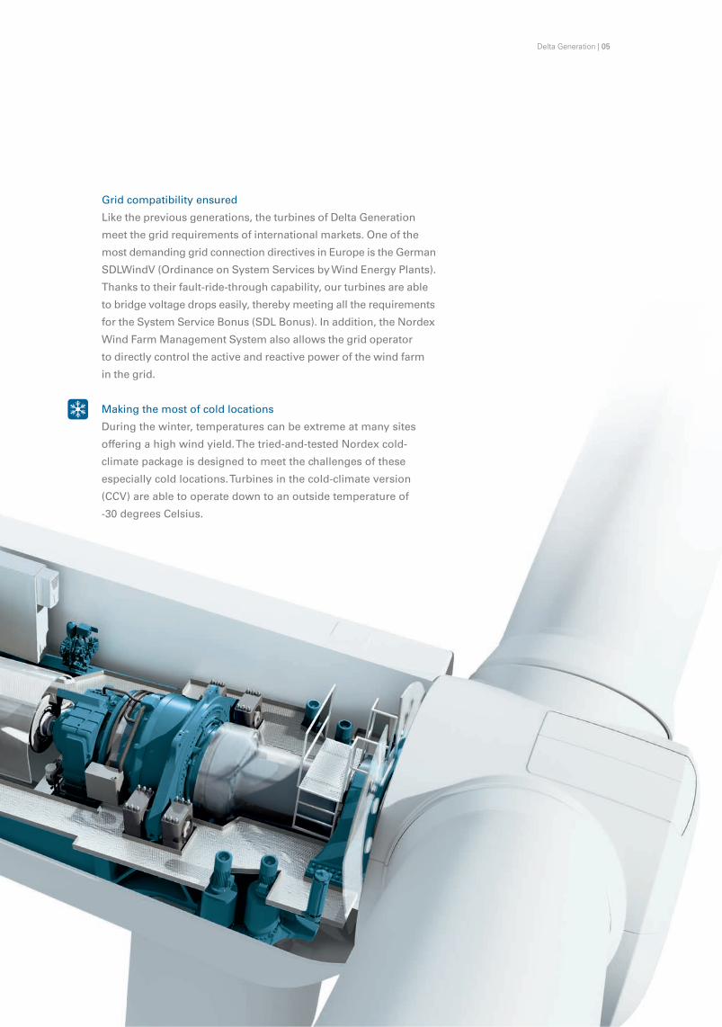
Gridcompatibilityensured
Likethepreviousgenerations,theturbinesofDeltaGeneration
meetthegridrequirementsofinternationalmarkets.Oneofthe
mostdemandinggridconnectiondirectivesinEuropeistheGerman
SDLWindV(OrdinanceonSystemServicesbyWindEnergyPlants).
Thankstotheirfault-ride-throughcapability,ourturbinesareable
tobridgevoltagedropseasily,therebymeetingalltherequirements
fortheSystemServiceBonus(SDLBonus).Inaddition,theNordex
WindFarmManagementSystemalsoallowsthegridoperator
todirectlycontroltheactiveandreactivepowerofthewindfarm
inthegrid.
Makingthemostofcoldlocations
Duringthewinter,temperaturescanbeextremeatmanysites
offeringahighwindyield.Thetried-and-testedNordexcold-
climatepackageisdesignedtomeetthechallengesofthese
especiallycoldlocations.Turbinesinthecold-climateversion
(CCV)areabletooperatedowntoanoutsidetemperatureof
-30degreesCelsius.
Delta Generation | 05

IndevelopingDeltaGeneration,wehavemetourmaintarget–
tocutthecostofenergy.TheseNordexmulti-megawattturbines
deliverupto31percentmoreyieldfromthesites,making
DeltaGenerationturbinesaparticularlyworthwhileinvestment.
Larger:Rotors
Nordexhasdesignedtheturbinestouseamuchlargerrotorfor
eachwindclass.Thisproduceshigheryields.Forexample,
therotordiameterformachinesforstrong-windlocationswas
increasedbytenmetrescomparedtothepreviousmodel,resulting
ina23percentincreaseinsweptarea.Therotorforsiteswith
moderatewindspeedsis17metreslarger:a37percentincrease
inrotorsweep.Withits14metrelargerdiameter,therotorfor
light-windsitesoffersa25percentincreaseinsweptarea.
ECONOMIC EFFICIENCY Higheryieldsreducethecostofenergy
06 | Delta Generation

Stronger:RatedOutput
WiththeN100/3300,Nordexhasraisedtheratedoutputofthe
strongwindturbinebymorethan30percent.TheN117/3000is
designedformoderatewindspeedsandhasa20percenthigher
ratedoutputthanthepreviousmodel.Theincreaseinratedout-
putamountsto25percentfortheN131/3000light-windturbine.
ThishasapositiveeffectontheenergyyieldsoftheDeltaturbines.
Inspiteoftheconsiderableincreaseinoutput,thesoundpower
levelsremainstableforeachclass.WiththeN131/3000,Nordex
hasfurtherreducedthesoundpowerleveloftheturbinefor
light-windsites.
Higher:Towers
Newandhigherhubheightsproduceevengreateryield
increasesandmakesitingpossible,eveninwoodedareasor
locationswithcomplextopography.Forthefirsttime,Nordexis
offeringatubularsteeltowerwithahubheightof100metresfor
strongwindlocationsandonewithahubheightof120metres
forsiteswithmoderatewindspeeds.
Smarter:Anti-IcingSystems
Particularlyinfrostregions,iceformsonrotorbladesinthewinter
months.Icingcanreducetheefficiencyofawindturbinegenera-
toraswellasloweringitsavailability.TheprovenNordexanti-icing
systemheatsthemostaerodynamicallyimportantareasofthe
rotorbladesandefficientlyreducesicinglevels.Nordex
customerscanrelyontheirturbinesfordependableyieldsand
maximumavailabilityincoldregions.
Delta Generation | 07

Toensurethatourturbinesperformreliably,weconductexhaus-
tivetests.Wecertifythequalityofallcomponentsandmanufac-
tureinamodernlineproduction.Theaverageavailabilityofall
turbinescoveredbyNordexServicestandsat98percent.Weensure
thishighlevelofavailabilitybyconsistentlyfurtherdevelopingthe
vitalimportantsystems.Thiscontributestoafurtherreductionin
thecostofenergy.
Extremetestsforhardwareandsoftware
IntheNordexTestCentre,engineerstestthecomponentsand
systemsofthenewturbinegenerationundersimulatedwind
andweatherconditions.Bysubjectingthemtostrainsinexcess
oftheusualspecifications,Nordexensuresthatthedesignmeets
allcriteria,deliveringahigh-quality,matureproductfor
serialproduction.
Highestindustrialstandards
Nordexcontinuestomeethighindustrialstandards,manufac-
turingthenacelleandhubmodulesinacontinuousflowprocess.
Manyofthestepsneededforassemblyandcommissioningare
performedintheprotectedfactoryhallbeforetheequipmentis
shippedtothesite.
08 | Delta Generation
In the Nordex Test Centre engineers ensure the quality of components.
QUALITY AND RELIABILITY A focus on high availability

Advancedcontrolinfrastructure
Nordexhasequippedthenewturbinegenerationwiththe
Profinetcommunicationsystem.Itsethernet-basedfieldbus
transfersturbinedatarapidly,reliablyandbypriority.Allactuators
andsensorsintheturbinecontrolsystems,aswellasthedifferent
moduleoptions,aredirectlyintegratedintothenetwork.This
ensuresimproveddiagnosticsandthereliabilityofthesystem.
Optimiseddrivetrain
ThedrivetraindesignofDeltaGenerationreducestheforces
actingontheindividualcomponents,takinggreaterstrainoff
therobustrotorbearing.Innovationsinthecoolingsystemofthe
drivetrainensureconstanttemperaturesoverawideoperating
range–withlowerinternalenergyconsumption.
Delta Generation | 09

10 | Delta Generation
SERVICE AND HSE FastandsafeturbineO&M
DeltaGenerationisdesignedsothatserviceoperationscan
beconductedrapidlyandsafely.Thisreducesongoing
operationalcosts.Wemakenocompromisewhenitcomes
toHSE–theturbinesofthenewgenerationmeetthemost
stringentrequirements.
Protectedhubaccess
Thenewspinner,acompletehousingfortherotorhub,provides
rapidandprotectedaccesstothehub.Thismeansthatservice
workcanbecarriedoutinawiderrangeofwindandweather
conditions.Thisisofparticularadvantageincoldregions–
makingitpossibletoreducedowntimesforservicepurposes.
The arrow indicates the protected hub access via the spinner.

Delta Generation | 11
Ergonomicsandsafety
Whenweweredevelopingthenewmulti-megawattgeneration,
wegavehighprioritytodesigningtheturbinesasaparticularly
safeandspaciousworkplace.Incaseofanemergency,the
platformalsooffersextendedescapeandrescueroutes.All
systemsareeasilyaccessibleformaintenance.Nacellecompon-
entsweighinglessthanonetonnecanbereachedwiththe
onboardcraneand,ifnecessary,canbeexchangedwithout
additionalequipment.
Annualserviceinterval
ThetechnicaldesignofDeltaGenerationallowsforanannual
serviceinterval.Automaticlubricationofthebearingsinthepitch
systemreplacesmanualprocesses.Thesebearings,aswellas
themainbearingandthegeneratorbearings,aresuppliedauto-
maticallywithlubricant,makingthemlesssusceptibletowear.
Thisminimisestheservicerequirementsandreducesthe
O&Mexpenses.
Yawn-1concept
Theyawsystemrunswithfourdrivesinstandardoperation.
However,shouldonedrivebreakdown,theturbinecancontinue
toruntemporarilyonthreedrives,makingitpossibletoplanany
neededservicework.Thisconceptincreasesturbineavailability
andreducesservicecosts.

12 | Delta Generation
DELTA GENERATION IN THE FIELDTried-and-testedperformance
Inmid-2013,NordexinstalledthefirstDeltaGenerationturbines
forhighandmediumwindspeedsintheJannebywindfarmin
Germany.Bynow,thefamilyhasanewmember–thelightwind
modelN131/3000hasbeeninstalledandcommissionedinthe
samewindfarm.
Certificationandfieldvalidationarerunningonschedule:all
DIBttypeapprovalsandtheInternationalIECDesignEvaluation
ConformityStatements(DECS)havebeenobtainedforthe
DeltaGenerationturbines.TheIECTypeCertificate(TC)has
beenawardedforN100/3300andN117/3000.
Theprincipalmeasurementresultsforalltypeswererecorded
attheJannebysite.Particularlyimportant:thesoundpowerlevels
ofthethreeturbineswereconfirmedbyexternalmeasurements.
Thegermanunitcertificatesaswellthepowercurveshavealready
beenissuedfortheN117/3000andtheN100/3300.

Delta Generation | 13

8.5m/s 9.0m/s 9.5m/s 10.0m/s
40.0%
30.0%
20.0%
10.0%
0.0%
∆ AEP in per cent compared to N90/2500-R80
23.7%22.9%22.1%21.2%
Calculation of AEP based on air density of 1.225 kg/m³, wind shear of 0.2 and Weibull shape parameter of k = 2.0
The N100/3300 generates between 21.2 and 31.4 per cent more AEP compared to the preceding IEC 1 model.
30.9%31.1%31.3%31.4%
Wind speed at 80 m
N100/3300 on a hub height of 100 m
N100/3300 on a hub height of 75 m
14 | Delta Generation
SOLUTION FOR STRONG WIND Highyieldsinroughclimates
Windsiteswitharoughenvironmentcallformature,robust
technology.WiththeturbinesofDeltaGeneration,Nordexoffers
theproven100-metrerotor,nowalsoforIEC1locations.Thanks
tothelargerotordiameterandthehigherratedoutput,the
N100/3300obtainsmuchhigherenergyyieldsatsiteswithstrong
windscomparedtothepreviousmodel.Thisturbineisavailable
withhubheightsof75,85and100metres.

Delta Generation | 15
The powerful N100/3300 is the first choice for strong wind sites.
N100/3300
Operatingdata
Rated power 3,300 kW
Cut-in wind speed 3.5 m/s
Cut-out wind speed 25 m/s
Rotor
Diameter 99.8 m
Swept area 7,823 m²
Operating range rotational speed 9.0–16.1 rpm
Rated rotational speed 14.3 rpm
Tip speed 75 m/s
Speed control Variable via microprocessor
Overspeed control Pitch angle
Gearbox
Type 3-stage gearbox (planetary-planetary-spur gear)
Generator
Construction Doubly-fed asynchronous generator
Cooling system Liquid / air cooling
Voltage 660 V
Grid frequency 50 / 60 Hz
Brakesystem
Main brake Aerodynamic brake (Pitch)
Holding brake Disk brake
Lightningprotection Fully compliant with IEC 61400-24
Tower
Construction Tubular steel tower
Hub height/Certification 75 m / IEC 1a, DIBt 3 85 m / IEC 1a100 m / IEC 1a, DIBt 3
TECHNICAL DATA

7.0m/s 7.5m/s 8.0m/s 8.5m/s
40.0%
30.0%
20.0%
10.0%
0.0%
Wind speed at 100 m
N117/3000 on a hub height of 120 m
N117/3000 on a hub height of 91 m
∆ AEP in per cent compared to N100/2500-R100
Calculation of AEP based on air density of 1.225 kg/m³, wind shear of 0.2 and Weibull shape parameter of k = 2.0
The N117/3000 generates between 21.7 and 33.6 per cent more AEP compared to the preceding IEC 2 model.
29.7%30.8%33.6% 32.1%
22.4% 22.1% 21.9% 21.7%
16 | Delta Generation
WiththeN117/3000,Nordexnowoffersanevenmoreeconomical
turbineforIEC2locations.Theenlargedrotorsweepandhigher
ratedoutputdelivermuchhigheryields.TheN117/3000isavailable
ontubularsteeltowersof91or120metres,aswellasonahybrid
towerof141metres.Therefore,itissuitableforchallengingsites
aswell.
Toensurehighyieldsatsitesincoldclimates,Nordexequipsthe
N117/3000withtheefficientanti-icingsystemasanoption.
SOLUTION FOR MODERATE WIND Economicalatawiderangeofsites

Delta Generation | 17
TECHNICAL DATA
The N117/3000 – economical at a wide range of sites.
N117/3000
Operatingdata
Rated power 3,000 kW
Cut-in wind speed 3.0 m/s
Cut-out wind speed 25 m/s
Rotor
Diameter 116.8 m
Swept area 10,715 m²
Operating range rotational speed 7.9–14.1 rpm
Rated rotational speed 12.6 rpm
Tip speed 77 m/s
Speed control Variable via microprocessor
Overspeed control Pitch angle
Gearbox
Type 3-stage gearbox (planetary-planetary-spur gear)
Generator
Construction Doubly-fed asynchronous generator
Cooling system Liquid / air cooling
Voltage 660 V
Grid frequency 50 / 60 Hz
Brakesystem
Main brake Aerodynamic brake (Pitch)
Holding brake Disk brake
Lightningprotection Fully compliant with IEC 61400-24
Tower
Construction Tubular steel tower Hybridtower
Hub height/Certification 91 m / IEC 2a, DIBt 3 120 m / IEC 2a, DIBt 2 141 m, DIBt 2

40.0%
30.0%
20.0%
10.0%
0.0%
Calculation of AEP based on air density of 1.225 kg/m³, wind shear of 0.2 and Weibull shape parameter of k = 2.0
The N131/3000 generates between 27.4 and 28.6 per cent more AEP compared to the preceding IEC3 model.
6.0m/s 6.5m/s 7.0m/s 7.5m/s Wind speed at 91 m
N131/3000 on a hub height of 99 m
Comparison based on identical hub height
∆ AEP in per cent compared to N117/2400-R91
27.4%27.8%28.6% 28.2%
21.1% 21.8% 22.1% 22.4%
Highyieldeveninregionswithlightwind:thankstoitsenlarged
rotorsweepandhigherratedoutput,theN131/3000generatesa
muchhigheryieldatlight-windlocations.Theturbineisavailableon
tubularsteeltowerswithhubheightsof99or114metres.
Nordexlimitsthesoundpowerlevelofthelight-windturbineto
max.104.5dB(A)–acrucialfactorforoptimisingwindfarmsand
facilitatingpermitting.
Toensurehighyieldsatsitesincoldclimates,Nordexequipsthe
N131/3000withtheefficientanti-icingsystemasanoption.
18 | Delta Generation
SOLUTION FOR LIGHT WIND Maximumefficiencyinthe3MWsegment
Delta Generation | 19
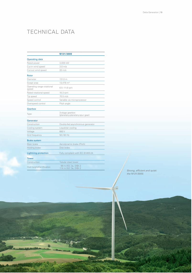
Strong, efficient and quiet: the N131/3000.
N131/3000
Operatingdata
Rated power 3,000 kW
Cut-in wind speed 3.0 m/s
Cut-out wind speed 20 m/s
Rotor
Diameter 131.0 m
Swept area 13,478 m²
Operating range rotational speed 6.5 –11.6 rpm
Rated rotational speed 10.3 rpm
Tip speed 70.5 m/s
Speed control Variable via microprocessor
Overspeed control Pitch angle
Gearbox
Type 3-stage gearbox (planetary-planetary-spur gear)
Generator
Construction Doubly-fed asynchronous generator
Cooling system Liquid / air cooling
Voltage 660 V
Grid frequency 50 / 60 Hz
Brakesystem
Main brake Aerodynamic brake (Pitch)
Holding brake Disk brake
Lightningprotection Fully compliant with IEC 61400-24
Tower
Construction Tubular steel tower
Hub height/Certification 99 m / IEC 3a, DIBt 2 114 m / IEC 3a, DIBt 2
TECHNICAL DATA

Nordex SELangenhornerChaussee60022419Hamburg,GermanyPhone:+4940300301000Email:[email protected]
ServiceAreaGermany Nordex Energy GmbHLangenhornerChaussee60022419Hamburg,GermanyPhone:+4940300301000Email:[email protected]
AsiaNordex ChinaRoom808,FirstShanghaiCenter,No.39LiangmaqiaoRoad,ChaoyangDistrictBeijing100125,ChinaPhone:+861084535188Email:[email protected]
BeneluxNordex Energy GmbHMarconiweg148501XMJoure,theNetherlandsPhone:+31513412354Email:[email protected]
ChileNordex Chile SpAAv.PresidenteRiesco5335,Piso9,LasCondes,Santiago,ChilePhone:+56227143866Email:[email protected]
Denmark,BalticcountriesNordex Energy GmbHNielsBohrsVej12b6000Kolding,DenmarkPhone:+4575734400Email:[email protected]
FinlandNordex Energy GmbH Hiilikatu300180Helsinki,FinlandPhone:+358103230060Email:[email protected]
FranceNordex France S.A.S.1,RuedelaProcession93217LaPlaineSaint-Denis,FrancePhone:+33155934343Email:[email protected]
GermanyNordex Energy GmbHCentroallee263a46047Oberhausen,GermanyPhone:+492088241120Email:[email protected]
IrelandNordex Energy Ireland Ltd.ClonmelHouse,ForsterWaySwords,Co.Dublin,IrelandPhone:+35318970260Email:[email protected]
ItalyNordex Italia S.r.l.VialeCittàd’Europa67900144Rome,ItalyPhone:+39068346301Email:[email protected]
NorwayNordex Energy GmbH RegusBusinessCentreKarenslystAllé8b,3rdfloor0278Oslo,NorwayPhone:+4796623043Email:[email protected]
PakistanNordex Pakistan Private Ltd.187GomalRoad,E-7Islamabad44000,PakistanPhone:+92518441101Email:[email protected]
PolandNordex Polska Sp. z o.o.Ul.Puławska182,6thfloor02-670Warschau,PolandPhone:+48222030140Email:[email protected]
PortugalNordex Energy GmbH Sucursal em PortugalRuaEng.º -FerreiraDias,n.º -728EdifícioANFPorto,Fracção2.104100-246Porto,PortugalPhone:+351229388972Email:[email protected]
RomaniaNordex Energy Romania S.R.L. Strada CA Rosetti nr 17Etaj 7, birou 703, sector 2020011 Bukarest, RomaniaPhone:+40215270556Email:[email protected]
SpainNordex Energy Ibérica S. A.Pso.delaCastellana,232º-a28046Madrid,SpainPhone:+34917000356Email:[email protected]
SouthAfricaNordex Energy South Africa (RF) (Pty) Ltd.WembleySquare3,2ndFloor80McKenzieStreetGardens,CapeTown8001,SouthAfricaPhone:+27214640200Email:[email protected]
SwedenNordex Sverige ABKungsängsvägen25b75323Uppsala,SwedenPhone:+4618185900Email:[email protected]
TurkeyNordex Enerji A.Ş.Havaalanı Kavşağı EGS Business ParkBloklarıB1BlokKat:15No:451-452-45334149Yeşilköy, Istanbul, TurkeyPhone:+902124683737Email:[email protected]
UKNordex UK Ltd.Suite4,EgertonHouseTheTowersBusinessPark,WilmslowRoadDidsburyM202DX,UKPhone:+441614459900Email:[email protected]
UruguayNordex Energy Uruguay S.A.Rizal3555,Piso2CP11300Montevideo,UruguayPhone:+59826245570Email:[email protected]
USA,NorthAmericaNordex USA, Inc. 300SouthWackerDrive,Suite1500Chicago,Illinois60606,USAPhone:+13123864100Email:[email protected] Energy GmbHLangenhornerChaussee60022419Hamburg,GermanyPhone:+4940300301000Email:[email protected]
WORLDWIDE OFFICES andsubsidiaries:
©Nordex2014.Allrightsreserved.Thecontentsofthisdocumentareforinformationalpurposesonlyandmaybesubjecttochangewithoutnotice.Norepresentationorwarranty,whetherexpressedorimplied,isgivenorshouldberelieduponastotheadequacyandaccuracyoftheinformationcontainedherein.
Reproduction,useordisclosuretothirdparties,withoutourwrittenconsent,isnotpermitted.
Asof:09/2015

Date 27.06.2017
Design dataNominal power 3,400 kW (LV-side)Cut-in wind speed 3 m/sNominal wind speed 12 m/sCut-out wind speed 22 m/sOperating temperature range -20 – +40 °C
CertificationHub height Wind class DIBt Wind zone86 – 89 m IEC S (based on IEC IIA) WZ 4, GK II116 – 119 m IEC S (based on IEC IIIA) WZ 3, GK II136 – 139 m IEC S (based on IEC IIIA) WZ 3, GK II
RotorDiameter 122 mRotor area 11,690 m²Rotor speed 6.1 – 11.3 1/min (+15 %)Power control Electrical pitch
Rotor bladeBlade length 59.8 mType Glass fibre-reinforced plastic (GFRP)Max. chord width 3.9 m
Gear systemType Three-stage planetary / spur gearboxGear ratio i = approx. 127Type of suspension Three-point contact suspension
WeightRotor blade Approx. 15 tNacelle without drive train Approx. 46 tRotor Hub Approx. 26 t
Electrical systemNominal power 3,400 kW (LV-side)Nominal voltage 10/20/30 kVNominal frequency 50 HzGenerator Induction generator (squirrel cage rotor)Generator protection class IP 54Stator voltage 580 VSpeed range 735 – 1,356 1/minConverter type Full converter with DC intermediate circuitTransformer Internal Transformer (ITS)
Sound power levelMaximum sound power level 104.5 db (A)
Power curve
Senvion GmbH
Überseering 10
22297 Hamburg
T +49 40 5555090-0
senvion.com
Published by and copyright © 2016 Senvion GmbH. All rights reserved. This document is forinformation purposes only and subject to change at any time. No guarantees are given. Allobligations arise from a corresponding contract. Reproduction, use or distribution without priorwritten permission from Senvion GmbH is prohibited. Status 2016.
Powered by TCPDF (www.tcpdf.org)

Date 27.06.2017
Design dataNominal power 3,600 kW (LV-side)Cut-in wind speed 3 m/sNominal wind speed 11.5 m/sCut-out wind speed 22 m/sOperating temperature range -20 – +40 °C
CertificationHub height Wind class DIBt Wind zone107 – 110 m IEC S (based on IEC IIB) WZ 3, GK II127 – 130 m IEC IIIA WZ 2, GK II157 – 160 m IEC IIIA WZ 2, GK II
RotorDiameter 140 mRotor area 15,394 m²Rotor speed 6.3 – 9.6 1/min (+25 %)Power control Electrical pitch
Rotor bladeBlade length 68.5 mType Glass fibre-reinforced plastic (GFRP)Max. chord width 4 m
Gear systemType Three-stage planetary / spur gearboxType of suspension Three-point contact suspension
Electrical systemNominal power 3,600 kW (LV-side)Nominal voltage 600 VNominal frequency 50 HzGenerator Induction generator (squirrel cage rotor)Generator protection class IP 54Converter type Full converter with DC intermediate circuitTransformer Internal Transformer (ITS)
Sound power levelMaximum sound power level 104 db (A)
Power curve
Senvion GmbH
Überseering 10
22297 Hamburg
T +49 40 5555090-0
senvion.com
Published by and copyright © 2016 Senvion GmbH. All rights reserved. This document is forinformation purposes only and subject to change at any time. No guarantees are given. Allobligations arise from a corresponding contract. Reproduction, use or distribution without priorwritten permission from Senvion GmbH is prohibited. Status 2016.
Powered by TCPDF (www.tcpdf.org)

siemens.com/wind
Greater returns. Greater reason to celebrate.Introducing the SWT-2.625-120
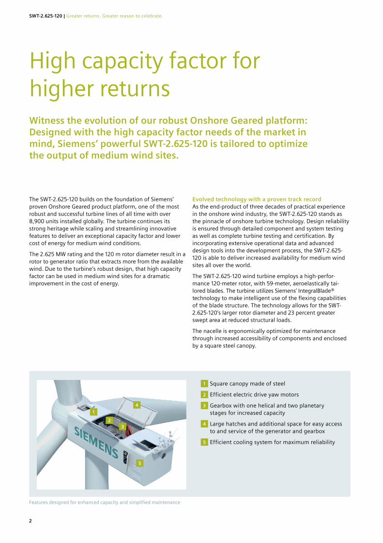
The SWT-2.625-120 builds on the foundation of Siemens’ proven Onshore Geared product platform, one of the most robust and successful turbine lines of all time with over 8,900 units installed globally. The turbine continues its strong heritage while scaling and streamlining innovative features to deliver an exceptional capacity factor and lower cost of energy for medium wind conditions.
The 2.625 MW rating and the 120 m rotor diameter result in a rotor to generator ratio that extracts more from the available wind. Due to the turbine’s robust design, that high capacity factor can be used in medium wind sites for a dramatic improvement in the cost of energy.
Evolved technology with a proven track record As the end-product of three decades of practical experience in the onshore wind industry, the SWT-2.625-120 stands as the pinnacle of onshore turbine technology. Design reliability is ensured through detailed component and system testing as well as complete turbine testing and certification. By incorporating extensive operational data and advanced design tools into the development process, the SWT-2.625-120 is able to deliver increased availability for medium wind sites all over the world.
The SWT-2.625-120 wind turbine employs a high-perfor-mance 120-meter rotor, with 59-meter, aeroelastically tai-lored blades. The turbine utilizes Siemens’ IntegralBlade® technology to make intelligent use of the flexing capabilities of the blade structure. The technology allows for the SWT-2.625-120’s larger rotor diameter and 23 percent greater swept area at reduced structural loads.
The nacelle is ergonomically optimized for maintenance through increased accessibility of components and enclosed by a square steel canopy.
Witness the evolution of our robust Onshore Geared platform: Designed with the high capacity factor needs of the market in mind, Siemens’ powerful SWT-2.625-120 is tailored to optimize the output of medium wind sites.
High capacity factor for higher returns
Features designed for enhanced capacity and simplified maintenance
1
23
4
5
Square canopy made of steel
Efficient electric drive yaw motors
Gearbox with one helical and two planetary stages for increased capacity
Large hatches and additional space for easy access to and service of the generator and gearbox
Efficient cooling system for maximum reliability
1
2
3
4
5
2
SWT-2.625-120 | Greater returns. Greater reason to celebrate.
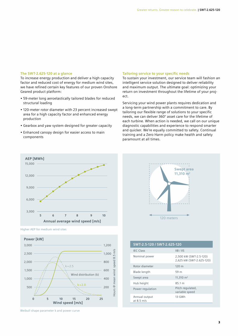
The SWT-2.625-120 at a glance To increase energy production and deliver a high capacity factor and reduced cost of energy for medium wind sites, we have refined certain key features of our proven Onshore Geared product platform:
• 59-meter long aeroelastically tailored blades for reduced structural loading
• 120-meter rotor diameter with 23 percent increased swept area for a high capacity factor and enhanced energy production
• Gearbox and yaw system designed for greater capacity
• Enhanced canopy design for easier access to main components
Tailoring service to your specific needsTo sustain your investment, our service team will fashion an intelligent service solution designed to deliver reliability and maximum output. The ultimate goal: optimizing your return on investment throughout the lifetime of your proj-ect.
Servicing your wind power plants requires dedication and a long-term partnership with a commitment to care. By tailoring our flexible range of solutions to your specific needs, we can deliver 360° asset care for the lifetime of each turbine. When action is needed, we call on our unique diagnostic capabilities and experience to respond smarter and quicker. We’re equally committed to safety. Continual training and a Zero Harm policy make health and safety paramount at all times.
SWT-2.5-120 / SWT-2.625-120
IEC Class IIB / IIS
Nominal power 2,500 kW (SWT-2.5-120)2,625 kW (SWT-2.625-120)
Rotor diameter 120 m
Blade length 59 m
Swept area 11,310 m2
Hub height 85.1 m
Power regulation Pitch regulated,variable speed
Annual output at 8.5 m/s
13 GWh
120 meters
Swept area 11,310 m2
Higher AEP for medium wind sites
15,000
12,000
9,000
6,000
3,000
Annual average wind speed [m/s]
5 6 7 8 9 10
AEP [MWh]
Weibull shape parameter k and power curve
Power [kW]
Wind speed [m/s]
k = 2.5
k = 2.0
Wind distribution (k)
3,000 1,200
2,000 800
2,500 1,000
500 200
1,000 400
1,500 600
0 5 10 15 20 25
Ho
urs
@ m
ean
win
d s
pee
d 8
.5 m
/s
33
Greater returns. Greater reason to celebrate. | SWT-2.625-120
Published by Siemens Wind Power GmbH & Co. KG
Beim Strohhause 17-31 20097 Hamburg, Germany siemens.com/wind
For more information, please contact our Customer Support Center. Phone: +49 180 524 70 00 Fax: +49 180 524 24 71 (Charges depending on provider) Email: [email protected]
Article-No. WPON-B10009-03-7600 RS1501345BR1116
All rights reserved.
Trademarks mentioned in this document are the property of Siemens, its affiliates, or their respective owners.
Subject to changes and errors.
The information given in this document only contains general descriptions and/or performance features which may not always specifically reflect those described, or which may undergo modification in the course of further development of the products. The requested performance features are binding only when they are expressly agreed upon in the concluded contract.
siemens.com/wind
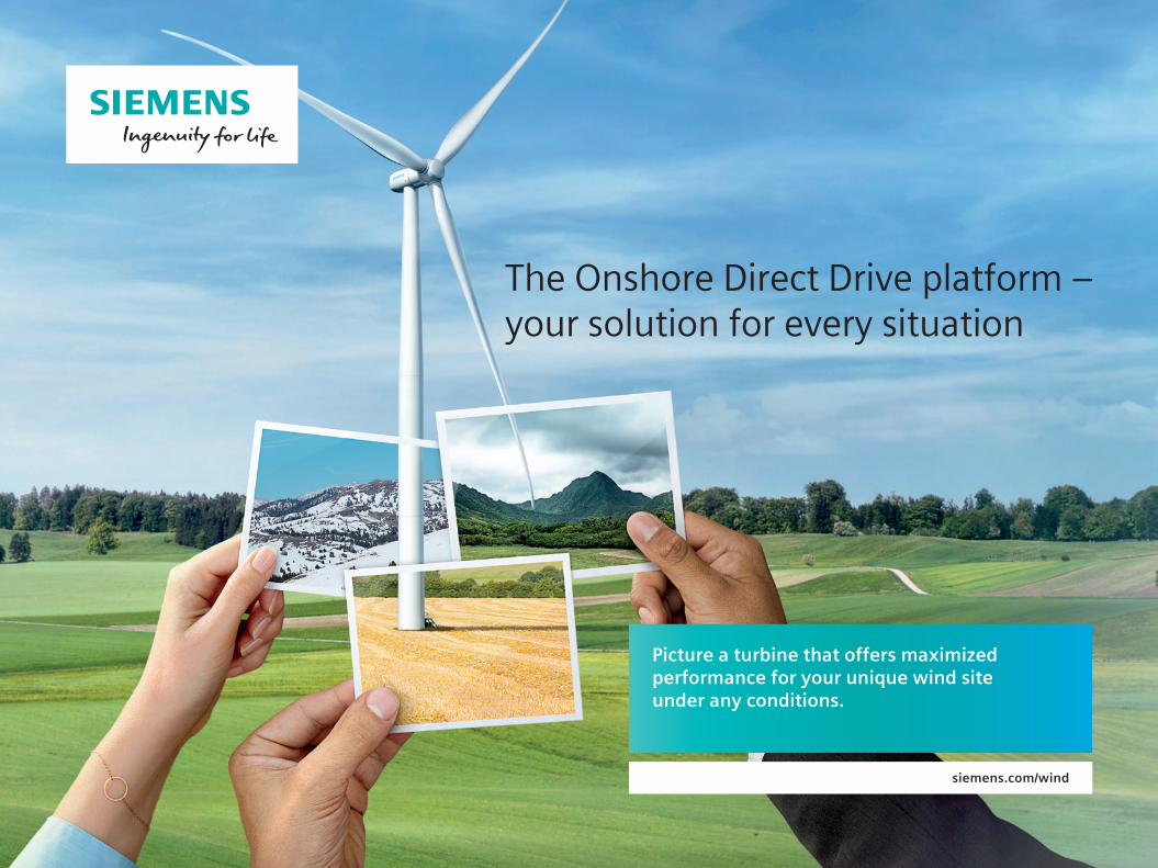
Picture a turbine that offers maximized performance for your unique wind site under any conditions.
The Onshore Direct Drive platform – your solution for every situation
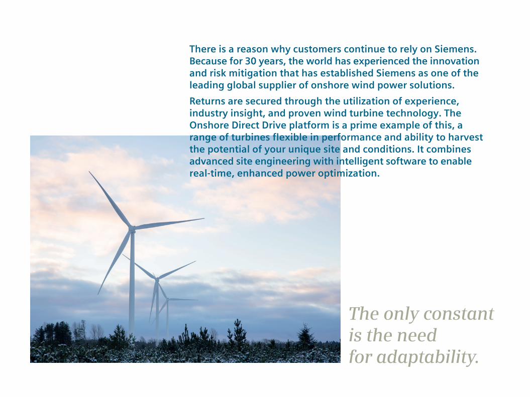
There is a reason why customers continue to rely on Siemens. Because for 30 years, the world has experienced the innovation and risk mitigation that has established Siemens as one of the leading global supplier of onshore wind power solutions.Returns are secured through the utilization of experience, industry insight, and proven wind turbine technology. The Onshore Direct Drive platform is a prime example of this, a range of turbines flexible in performance and ability to harvest the potential of your unique site and conditions. It combines advanced site engineering with intelligent software to enable real-time, enhanced power optimization.
The only constant is the need for adaptability.
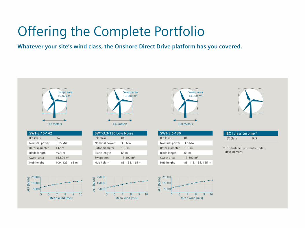
Offering the Complete PortfolioWhatever your site’s wind class, the Onshore Direct Drive platform has you covered.
SWT-3.15-142IEC Class IIIANominal power 3.15 MWRotor diameter 142 mBlade length 69.3 mSwept area 15,829 m2
Hub height 109, 129, 165 m
142 meters
IEC I class turbine *IEC Class IA/S
SWT-3.6-130IEC Class IIANominal power 3.6 MWRotor diameter 130 mBlade length 63 mSwept area 13,300 m2
Hub height 85, 115, 135, 165 m
SWT-3.3-130 Low NoiseIEC Class IIANominal power 3.3 MWRotor diameter 130 mBlade length 63 mSwept area 13,300 m2
Hub height 85, 135, 165 m
130 meters 130 meters
AEP
[MW
h]
AEP
[MW
h]
AEP
[MW
h]
Mean wind [m/s]Mean wind [m/s]Mean wind [m/s]
5000
15000
25000
5000
15000
25000
5000
15000
25000
5 6 7 8 9 10 5 6 7 8 9 10 5 6 7 8 9 10
Swept area 15,829 m2
Swept area 13,300 m2
Swept area 13,300 m2
* This turbine is currently under development

Direct Drive TechnologyEvolved design for unrivaled efficiency and adaptability.
The Onshore Direct Drive portfolio leverages proven, standard design components, while advancing certain key components and introducing new design concepts for increased flexibility.
The turbine generator has a simple and robust design that is expected to improve efficiency even at low loads. The direct drive technology in combination with the SICS controller enables real-time Power Optimization and can be applied using a single design across all wind classes.
This product portfolio was developed by Siemens by bringing together all the expertise, customer feedback, and experience of 30 years in wind power. By doing so, we are able to offer you a compact, simplified, and efficient range of wind turbines suited to any situation.
Every environment offers unique challenges. But wherever your site, Siemens wind turbines are designed to always offer optimized performance.
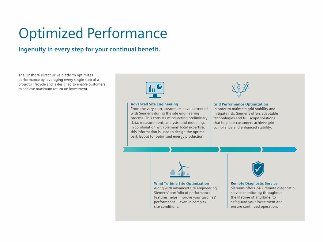
The Onshore Direct Drive platform optimizes performance by leveraging every single step of a project’s lifecycle and is designed to enable customers to achieve maximum return on investment.
Optimized PerformanceIngenuity in every step for your continual benefit.
Grid Performance OptimizationIn order to maintain grid stability and mitigate risk, Siemens offers adaptable technologies and full-scope solutions that help our customers achieve grid compliance and enhanced stability.
Remote Diagnostic ServiceSiemens offers 24/7 remote diagnostic-service monitoring throughout the lifetime of a turbine, to safeguard your investment and ensure continued operation.
Advanced Site EngineeringFrom the very start, customers have partnered with Siemens during the site engineering process. This consists of collecting preliminary data, measurement, analysis, and modeling. In combination with Siemens’ local expertise, this information is used to design the optimal park layout for optimized energy production.
Wind Turbine Site OptimizationAlong with advanced site engineering, Siemens’ portfolio of performance features helps improve your turbines’ performance – even in complex site conditions.

Real-time Power Optimization is supported by the direct drive generator – which produces power at a rating across a specific range – and Siemens’ intelligent Integrated Control System (SICS) working together.
The SICS is a control unit consisting of a turbine controller and a full-scale converter, which improves power production and power quality. Using innovative features and reading various parameters from the wind farm control system, the SICS offers real-time Power Optimization based on the needs and conditions
of the wind farm. By monitoring various sensors and producing power accordingly, the SICS, together with the SCADA system, enable different functions as condi-tions dictate, supporting noise-reduced operation, bat protection, and shadow-flicker avoidance, for example.
These features help achieve power production while remaining within the design load envelope, and power quality management. Combined, these features result in ‘intelligent’ wind turbines designed to optimize your AEP at all times.
Real-time Power OptimizationFlexible so you don’t need to be.
Optimized power production
Adaptive Control Srategy ACS uses software to allow the turbine to operate under complex climatic conditions, keeping the loads within the design envelope and minimizing power losses.
High Wind Ride Through The High Wind Ride Through feature overcomes shutdowns due to high wind, with an intelligent load-based reduction in output power, to enable more stable energy production.
Power Boost Function This controller feature can increasea a turbine’s AEP by up to 4% depending on site conditions, by raising the output limitation under specific operating conditions.
Optimized grid connection stabilityVariable Speed Range – improves turbine efficiency and supports reduced loads, acoustic noise, and flicker at low wind speedsLocal Voltage Control – controls reactive power in response to system voltage variations
Fault Ride Through – designed to withstand low/high-voltage events without tripping the machine
Inertial Response – supports grid stability in low frequency situations
Local Frequency Response – controls active power in response to under- and over-frequency events
Power quality – operates within harmonic content and flicker limits
Pow
er
Pow
er
Pow
er
Wind Speed Wind Speed Wind Speed20m/s 25m/s
Standard operationACS level 1ACS level 2

Nacelle• Proven components, rigorously tested for
improved reliability
• One nacelle and generator hub for all wind condi-tions helps drive down LCoE
• Innovative direct cooling system for improved efficiency
• Upgraded generator, yaw and SICS converter for increased performance
• Simple layout of components creates a comfortable workspace for technicians
Blades• Aeroelastic tailoring of blades has demonstrated
optimized energy harvesting while staying within the design load envelope
• Hybrid carbon technology is used to achieve a lightweight design for the larger rotor used at onshore low wind sites
• DinoTail® Next Generation serrations and blade add-ons are designed to control noise levels with-out sacrificing performance
Tower• Proven, cost-efficient tubular steel tower
concept for short installation time for all wind conditions
• A range of tower heights are offered in each wind class
• 165 m hybrid tower design allows optimal energy extraction in low wind conditions
Proven TechnologyDesigned for maximum reliability.
Generator
Canopy
Nacelle support structure
Direct cooling system
Lightning protection, weather station, and flight lights

Published by Siemens AG 2016
Wind Power and Renewables Division Beim Strohhause 17-31 20097 Hamburg, Germany siemens.com/wind
For more information, please contact our Customer Support Center. Phone: +49 180 524 70 00 Fax: +49 180 524 24 71 (Charges depending on provider) Email: [email protected]
Article-No. WPON-B10021-00-7600 RS 1501275BR
All rights reserved.
Trademarks mentioned in this document are the property of Siemens AG, its affiliates, or their respective owners.
Subject to change without prior notice.
The information contained in this document contains general descriptions of the technical options available, which may not apply in all cases. The required technical options should therefore be specified in the contract.

Wind energy means the world to us. And we want it to mean the
world to our customers, too, by maximising your profits and
strengthening the certainty of your investment in wind power.
That’s why, together with our partners, we always strive to deliver
cost-effective wind technologies, high quality products and first
class services throughout the entire value chain. And it’s why we
put so much emphasis on the reliability, consistency and predict-
ability of our technology.
We have more than 35 years’ experience in wind energy. During
that time, we’ve delivered more than 83 GW of installed capacity
in 75 countries. That is more than anyone else in the industry. We
currently monitor over 33,000 wind turbines across the globe.
All tangible proof that Vestas is the right partner to help you
realise the full potential of your wind site.
What is the 4 MW Platform today?The Vestas 4 MW platform* was introduced in 2010 with the
launch of the V112-3.0 MW®. Over 13 GW of the 4 MW platform
has been installed all over the world onshore and offshore making
it the obvious choice for customers looking for highly flexible and
trustworthy turbines.
Since then the 4 MW platform was upgraded and new variants
were introduced utilising untapped potential of the platform.
All variants carry the same nacelle design and the hub design
has been re-used to the largest extend possible. In addition, our
engineers have increased the nominal power across the entire
platform improving your energy production significantly.
With this expansion, the 4 MW platform covers all IEC wind
classes with a variety of rotor sizes and a higher rated output
power of up to 4.2 MW.
You can choose from the following turbines on the 4 MW platform:
· V105-3.45 MW™ – IEC IA
· V112-3.45 MW® – IEC IA
· V117-3.45 MW® – IEC IB/IEC IIA
· V117-4.0/4.2 MW™ – IEC IB/IEC IIA
· V126-3.45 MW® – IEC IIB/IIA
· V136-3.45 MW® – IEC IIB/IEC IIIA
· V136-4.0/4.2 MW™ – IEC IIB
· V150-4.0/4.2 MW™ – IEC IIIB
All variants of the 4 MW platform are based on the proven
technology of the V112-3.0 MW® with a full-scale converter,
providing you with superior grid performance.
Our 4 MW platform is designed for a broad range of wind and site
conditions, enabling you to mix turbines across your site or port-
folio of sites, delivering industry-leading reliability, serviceability
and exceptional energy capture, optimising your business case.
All turbine variants are equipped with the same ergonomically
designed and very spacious nacelle which makes it easier for
maintenance crews to gain access, so they can reduce the time
spent on service while maximizing the uptime without compro-
mising safety. All turbines can be installed and maintained using
standard installation and servicing tools and equipment further
reducing the operation and maintenance costs by minimising
your stock level of spare parts.
Are you looking for the maximum return on your investment in wind energy?
*Formerly named the Vestas 3 MW platform

+60,000The V112-3.45 MW® and the other 4 MW variants advance the already proven technology powering over 60,000 installed Vestas turbines worldwide - more than any other supplier.
How does our technology generate more energy?
More power for every wind siteV112-3.45 MW®, V117-3.45 MW®, V126-3.45 MW® and V136-
3.45 MW® are available with several Sound Optimised Modes to
meet sound level restrictions with an optimised production. The
power system enables superior grid support and it is capable of
maintaining production across severe drops in grid voltage, while
simultaneously minimising tower and foundation loads. It also
allows rapid down-rating of production to 10 per cent nominal
power.
Proven technologies - from the company that invented themThe 4 MW platform is a low-risk choice. It is based on the proven
technologies that underpin more than 60,000 Vestas turbines
installed around the world. Using the best features from across
the range, as well as some of the industry’s most stringently
tested components and systems, the platform’s reliable design
minimises downtime – helping to give you the best possible
return on your investment.
With an operating range that covers all wind classes, our 4 MW
platform delivers unrivalled energy production. The proven
blade technology from the V112-3.0 MW® is used on the V105-
3.45 MW™, the V112-3.45 MW®, V117-3.45 MW® and V117-
4.0/4.2 MW™. The industry known structural shell blades are
used on the V126-3.45 MW®, V136-3.45 MW®, V136-4.0/4.2
MW™ and V150-4.0/4.2 MW™- a technology which is also used
on the 2 MW V110-2.0 MW®, V116-2.0 MW™ and V120-2.0
MW™ variants.
Reliable and robustThe Vestas Test Centre is unrivalled in the wind industry. We test
most nacelle components using Highly Accelerated Life Testing
(HALT) to ensure reliability. For critical components, HALT identi-
fies potential failure modes and mechanisms. Specialised test
rigs ensure strength and robustness for the gearbox, generator,
yaw and pitch system, lubrication system and accumulators.
Our quality-control system ensures that each component is
manufactured to design specifications and performs at site. We
systematically monitor measurement trends that are critical to
quality, locating defects before they occur.
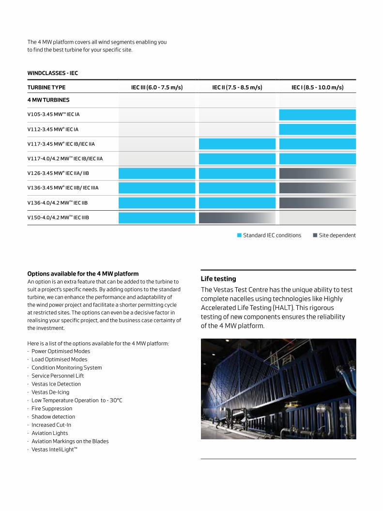
Life testing
The Vestas Test Centre has the unique ability to test complete nacelles using technologies like Highly Accelerated Life Testing (HALT). This rigorous testing of new components ensures the reliability of the 4 MW platform.
Options available for the 4 MW platformAn option is an extra feature that can be added to the turbine to
suit a project’s specific needs. By adding options to the standard
turbine, we can enhance the performance and adaptability of
the wind power project and facilitate a shorter permitting cycle
at restricted sites. The options can even be a decisive factor in
realising your specific project, and the business case certainty of
the investment.
Here is a list of the options available for the 4 MW platform:
· Power Optimised Modes
· Load Optimised Modes
· Condition Monitoring System
· Service Personnel Lift
· Vestas Ice Detection
· Vestas De-Icing
· Low Temperature Operation to - 30°C
· Fire Suppression
· Shadow detection
· Increased Cut-In
· Aviation Lights
· Aviation Markings on the Blades
· Vestas InteliLight™
TuRbine TyPe ieC iii (6.0 - 7.5 m/s) ieC ii (7.5 - 8.5 m/s) ieC i (8.5 - 10.0 m/s)
4 MW TuRbines
V105-3.45 MW™ IEC IA
V112-3.45 MW® IEC IA
V117-3.45 MW® IEC IB/IEC IIA
V117-4.0/4.2 MW™ IEC IB/IEC IIA
V126-3.45 MW® IEC IIA/ IIB
V136-3.45 MW® IEC IIB/ IEC IIIA
V136-4.0/4.2 MW™ IEC IIB
V150-4.0/4.2 MW™ IEC IIIB
■ Standard IEC conditions ■ Site dependent
WindCLasses - ieC
The 4 MW platform covers all wind segments enabling you
to find the best turbine for your specific site.

Is the 4 MW platform the optimal choice for your specific site?
One common nacelle – six different rotor sizesThe wind conditions on a wind project site are often not identical.
The 4 MW platform features a range of turbines that cover all
wind classes and combined across your site they can maximise
the energy output of your wind power plant.
Tip-height restrictions and strict grid requirementsWith a rotor size of 105 m, the V105-3.45 MW™ IEC IA is the
turbine that fits the most severe wind conditions. It has an ex-
tremely robust design for tough site conditions and is especially
suited for markets with tip-height restrictions and high grid
requirements.
Like all the other 4 MW turbines, the V105-3.45 MW™ is equipped
with a full-scale converter ensuring full compliance with the
challenging grid codes in countries like the UK and Ireland.
Cold climatesThe V112-3.45 MW®, V117-3.45 MW® , V117-4.0/4.2 MW™,
V126-3.45MW® and V136-3.45 MW® can be combined with
Vestas De-Icing and Vestas Ice Detection ensuring optimum
production in cold climates.
The Vestas De-Icing System is fully SCADA integrated and
can be triggered automatically or manually depending on your
de-icing strategy. Automatic control protects your investment,
optimising the trigger point so the turbine only stops to de-ice
when there is an expected net power production gain.
High- and medium-wind sitesThe V112-3.45 MW® IEC IA is a high-wind turbine and has a
very high capacity factor. Similar to the other 4 MW turbines,
the V112-3.45 MW® IEC IA turbine makes efficient use of its
grid compatibility and is an optimal choice for sites with MW
constraints.
On medium wind-sites, the V117-3.45 MW® IEC IB/IEC IIA,
V126-3.45 MW® IEC IIA/IIB, V136-3.45 MW® IEC IIB/IEC IIIA
and V136-4.0/4.2 MW IEC IIB are excellent turbine choices. A
combination of the variants can optimise your site layout and
improve your production significantly on complex sites.
Low-wind sitesBuilt on the same proven technology as the V112-3.0 MW®, the
V150-4.0/4.2 MW™ IEC IIIB is our best performer on low-wind
sites. The larger rotor enable greater wind capture, which in turn
produces more energy to reduce levelised cost of energy (LCOE).
The result is exceptional profitability in areas with low wind, and
new frontiers for wind energy investment.
Large Diameter Steel Towers (LDST) support the added rotor
size and rating of Vestas turbines to increase Annual Energy
Production on low-wind sites.
LDST is specially designed with a larger diameter in the
bottom section that allows for optimal strength at high hub
heights.
Maximising old permitsAlthough the V150-4.0/4.2 MW™ is one of the highest produc-
ing low wind turbines available, some old permits may simply be
too tight to accept it. Although the V117-3.45 MW®, V126-3.45
MW® and V136-4.0/4.2 MW™ are medium-wind turbines, they
still deliver an excellent business case on low-wind sites.
Due to the similar electrical properties and nacelle design, it is
easy to mix and match the turbines from the 4 MW platform to
maximise production on heavily constrained sites.
Knowledge about wind project planning is keyGetting your wind energy project up and operating as quickly as
possible is fundamental to its long-term success. One of the first
and most important steps is to identify the most suitable location
for your wind power plant. Vestas' SiteHunt® is an advanced ana-
lytical tool that examines a broad spectrum of wind and weather
data to evaluate potential sites and establish which of them can
provide optimum conditions for your project.
In addition, SiteDesign® optimises the layout of your wind power
plant. SiteDesign® runs Computational Fluid Dynamics (CFD)
software on our powerful in-house supercomputer Firestorm to
perform simulations of the conditions on site and analyse their
effects over the whole operating life of the plant. Put simply, it
finds the optimal balance between the estimated ratio of annual
revenue to operating costs over the lifetime of your plant, to
determine your project’s true potential and provide a firm basis
for your investment decision.
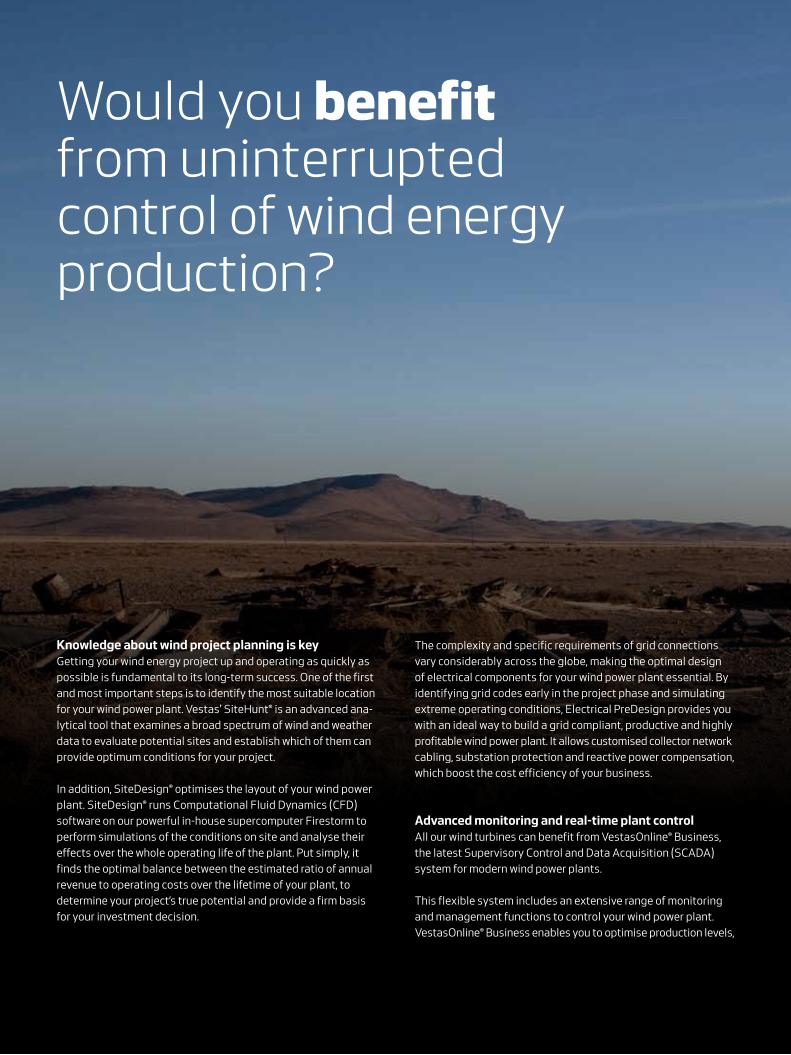
Would you benefit from uninterrupted control of wind energy production?
The complexity and specific requirements of grid connections
vary considerably across the globe, making the optimal design
of electrical components for your wind power plant essential. By
identifying grid codes early in the project phase and simulating
extreme operating conditions, Electrical PreDesign provides you
with an ideal way to build a grid compliant, productive and highly
profitable wind power plant. It allows customised collector network
cabling, substation protection and reactive power compensation,
which boost the cost efficiency of your business.
advanced monitoring and real-time plant controlAll our wind turbines can benefit from VestasOnline® Business,
the latest Supervisory Control and Data Acquisition (SCADA)
system for modern wind power plants.
This flexible system includes an extensive range of monitoring
and management functions to control your wind power plant.
VestasOnline® Business enables you to optimise production levels,

+33,000The Vestas Performance and Diagnostics Centre monitors more than 33,000 turbines worldwide. We use this information to con-tinually develop and improve our products and services.
monitor performance and produce detailed, tailored reports from
anywhere in the world. The VestasOnline® Power Plant Controller
offers scalability and fast, reliable real-time control and features
customisable configuration, allowing you to implement any control
concept needed to meet local grid requirements.
surveillance, maintenance and serviceOperating a large wind power plant calls for efficient manage-
ment strategies to ensure uninterrupted power production and
to control operational expenses. We offer 24/7 monitoring,
performance reporting and predictive maintenance systems to
improve turbine performance and availability. Predicting faults in
advance is essential, helping to avoid costly emergency repairs
and unscheduled interruptions to energy production.
Our Condition Monitoring System (CMS) assesses the status
of the turbines by analysing vibration signals. For example, by
measuring the vibration of the drive train, it can detect faults at
an early stage and monitor any damage. This information allows
pre-emptive maintenance to be carried out before the compo-
nent fails, reducing repair costs and production loss.
Additionally, our Active Output Management® (AOM) concept
provides detailed plans and long term agreements for service
and maintenance, online monitoring, optimisation and trouble-
shooting. It is possible to get a full scope contract, combining
your turbines’ state-of-the-art technology with guaranteed
time or energy-based availability performance targets, thereby
creating a solid base for your power plant investment. The Active
Output Management® agreement provides you with long term
and financial operational peace of mind for your business case.

V105-3.45 MW™ IEC IAFacts & figuresPOWeR ReGuLaTiOn Pitch regulated with
variable speed
OPeRaTinG daTa
Rated power 3,450 kW
Cut-in wind speed 3 m/s
Cut-out wind speed 25 m/s
Re cut-in wind speed 23 m/s
Wind class IEC IA
Standard operating temperature range from -20°C* to +45°C
with de-rating above 30°C
*Subject to different temperature options
sOund POWeR
Maximum 105.8 dB**
**Sound Optimised Modes dependent on site and country
ROTOR
Rotor diameter 105 m
Swept area 8,659 m²
Air brake full blade feathering with
3 pitch cylinders
eLeCTRiCaL
Frequency 50/60 Hz
Converter full scale
GeaRbOX
Type two planetary stages and
one helical stage
TOWeR
Hub height 72.5 m (IEC IA)
naCeLLe diMensiOns
Height for transport 3.4 m
Height installed
(incl. CoolerTop®) 6.9 m
Length 12.8 m
Width 4.2 m
Hub diMensiOns
Max. transport height 3.8 m
Max. transport width 3.8 m
Max. transport length 5.5 m
bLade diMensiOns
Length 51.2 m
Max. chord 4 m
Max. weight per unit for
transportation
70 metric tonnes
TuRbine OPTiOns
· High Wind Operation
· Power Optimised Mode up to 3.6 MW (site specific)
· Load Optimised Modes down to 3.0 MW
· Condition Monitoring System
· Service Personnel Lift
· Vestas Ice Detection
· Low Temperature Operation to -30°C
· Fire Suppression
· Shadow Detection
· Increased Cut-In
· Aviation Lights
· Aviation Markings on the Blades
· Vestas InteliLight™
annuaL eneRGy PROduCTiOn
assumptionsOne wind turbine, 100% availability, 0% losses, k factor =2, Standard air density = 1.225, wind speed at hub height
yearly average wind speed m/s
14.0
16.0
18.0
12.0
10.0
8.0
6.0
4.0
2.0
6.0 8.0 10.09.07.00
■ V105-3.45 MW™ IEC IA
GWh20.0

V112-3.45 MW® IEC IAFacts & figuresPOWeR ReGuLaTiOn Pitch regulated with
variable speed
OPeRaTinG daTa
Rated power 3,450 kW
Cut-in wind speed 3 m/s
Cut-out wind speed 25 m/s
Re cut-in wind speed 23 m/s
Wind class IEC IA
Standard operating temperature range from -20°C* to +45°C
with de-rating above 30°C
*subject to different temperature options
sOund POWeR
Maximum 106.7 dB**
**Sound Optimised Modes dependent on site and country
ROTOR
Rotor diameter 112 m
Swept area 9,852 m²
Air brake full blade feathering with
3 pitch cylinders
eLeCTRiCaL
Frequency 50/60 Hz
Converter full scale
GeaRbOX
Type two planetary stages and
one helical stage
TOWeR
Hub height 69 m (IEC IA) and 94 m (IEC IA)
naCeLLe diMensiOns
Height for transport 3.4 m
Height installed
(incl. CoolerTop®) 6.9 m
Length 12.8 m
Width 4.2 m
Hub diMensiOns
Max. transport height 3.8 m
Max. transport width 3.8 m
Max. transport length 5.5 m
bLade diMensiOns
Length 54.7 m
Max. chord 4 m
Max. weight per unit for
transportation
70 metric tonnes
TuRbine OPTiOns
· High Wind Operation
· Power Optimised Mode up to 3.6 MW (site specific)
· Load Optimised Modes down to 3.0 MW
· Condition Monitoring System
· Service Personnel Lift
· Vestas Ice Detection
· Vestas De-Icing
· Low Temperature Operation to - 30°C
· Fire Suppression
· Shadow detection
· Increased Cut-In
· Aviation Lights
· Aviation Markings on the Blades
· Vestas InteliLight™
annuaL eneRGy PROduCTiOn
assumptionsOne wind turbine, 100% availability, 0% losses, k factor =2, Standard air density = 1.225, wind speed at hub height
yearly average wind speed m/s
14.0
16.0
18.0
12.0
10.0
8.0
6.0
4.0
2.0
0
■ V112-3.45 MW™ IEC IA
GWh
6.0 8.0 10.09.07.0
20.0

V117-3.45 MW® IEC IB/IEC IIAFacts & figuresPOWeR ReGuLaTiOn Pitch regulated with
variable speed
OPeRaTinG daTa
Rated power 3,450 kW
Cut-in wind speed 3 m/s
Cut-out wind speed 25 m/s
Re cut-in wind speed 23 m/s
Wind class IEC IB/IEC IIA
Standard operating temperature range from -20°C* to +45°C
with de-rating above 30°C
*subject to different temperature options
sOund POWeR
Maximum 109.3 dB**
**Sound Optimised Modes dependent on site and country
ROTOR
Rotor diameter 117 m
Swept area 10,751 m²
Air brake full blade feathering with
3 pitch cylinders
eLeCTRiCaL
Frequency 50/60 Hz
Converter full scale
GeaRbOX
Type two planetary stages and
one helical stage
TOWeR
naCeLLe diMensiOns
Height for transport 3.4 m
Height installed
(incl. CoolerTop®) 6.9 m
Length 12.8 m
Width 4.2 m
Hub diMensiOns
Max. transport height 3.8 m
Max. transport width 3.8 m
Max. transport length 5.5 m
bLade diMensiOns
Length 57.2 m
Max. chord 4 m
Max. weight per unit for
transportation
70 metric tonnes
TuRbine OPTiOns
· High Wind Operation
· Power Optimised Mode up to 3.6 MW (site specific)
· Load Optimised Modes down to 3.0 MW
· Condition Monitoring System
· Service Personnel Lift
· Vestas Ice Detection
· Vestas De-Icing
· Low Temperature Operation to - 30°C
· Fire Suppression
· Shadow detection
· Increased Cut-In
· Aviation Lights
· Aviation Markings on the Blades
· Vestas InteliLight™
annuaL eneRGy PROduCTiOn
Hub heights 80 m (IEC IB), 91.5 m (IEC IB)
and 116.5 m (IEC IB/IEC IIA/DIBtS)
assumptionsOne wind turbine, 100% availability, 0% losses, k factor =2, Standard air density = 1.225, wind speed at hub height
yearly average wind speed m/s
14.0
16.0
18.0
12.0
10.0
8.0
6.0
4.0
2.0
0
GWh
6.0 8.0 10.09.07.0
■ V117-3.45 MW™ IEC IB/IEC IIA
20.0

Hub diMensiOns
Max. transport height 3.8 m
Max. transport width 3.8 m
Max. transport length 5.5 m
bLade diMensiOns
Length 57.2 m
Max. chord 4 m
Max. weight per unit for
transportation
70 metric tonnes
TuRbine OPTiOns
· High Wind Operation
· Power Optimised Mode up to 4.2 MW (site specific)
· Load Optimised Modes down to 3.6 MW
· Condition Monitoring System
· Service Personnel Lift
· Vestas Ice Detection
· Vestas De-icing
· Low Temperature Operation to - 30°C
· Fire Suppression
· Shadow detection
· Increased Cut-In
· Aviation Lights
· Aviation Markings on the Blades
· Vestas InteliLight®
annuaL eneRGy PROduCTiOn
V117-4.0/4.2 MWTM IEC IB/IEC IIA Facts & figuresPOWeR ReGuLaTiOn Pitch regulated with
variable speed
OPeRaTinG daTa
Rated power 4,000 kW
Cut-in wind speed 3 m/s
Cut-out wind speed 25 m/s
Re cut-in wind speed 23 m/s
Wind class IEC IB/IEC IIA
Standard operating temperature range from -20°C* to +45°C
with de-rating above 30°C
*subject to different temperature options
sOund POWeR
Maximum 106 dB**
**Sound Optimised Modes dependent on site and country
ROTOR
Rotor diameter 117 m
Swept area 10,751 m²
Air brake full blade feathering with
3 pitch cylinders
eLeCTRiCaL
Frequency 50/60 Hz
Converter full scale
GeaRbOX
Type two planetary stages and
one helical stage
TOWeR
Hub heights 91.5 m (IEC IB)
84 m (IEC IIA)
naCeLLe diMensiOns
Height for transport 3.4 m
Height installed
(incl. CoolerTop®) 6.9 m
Length
Width 4.2 m
12.8 m
assumptionsOne wind turbine, 100% availability, 0% losses, k factor =2,Standard air density = 1.225, wind speed at hub height
yearly average wind speed m/s
14.0
16.0
18.0
12.0
10.0
8.0
6.0
4.0
2.0
0
GWh
6.0 8.0 10.09.07.0
■ V117-4.0/4.2 MW™ IEC IB/IEC IIA
20.0

V126-3.45 MW® IEC IIB/IIAFacts & figuresPOWeR ReGuLaTiOn Pitch regulated with
variable speed
OPeRaTinG daTa
Rated power 3,450 kW
Cut-in wind speed 3 m/s
Cut-out wind speed 22.5 m/s
Re cut-in wind speed 20 m/s
Wind class IEC IIA
Standard operating temperature range from -20°C* to +45°C
with de-rating above 30°C
*subject to different temperature options
sOund POWeR
Maximum 110.1 dB**
**Sound Optimised Modes dependent on site and country
ROTOR
Rotor diameter 126 m
Swept area 12,469 m²
Air brake full blade feathering with
3 pitch cylinders
eLeCTRiCaL
Frequency 50/60 Hz
Converter full scale
GeaRbOX
Type two planetary stages and
one helical stage
TOWeR
naCeLLe diMensiOns
Height for transport 3.4 m
Height installed
(incl. CoolerTop®) 6.9 m
Length 12.8 m
Width 4.2 m
Hub diMensiOns
Max. transport height 3.8 m
Max. transport width 3.8 m
Max. transport length 5.5 m
bLade diMensiOns
Length 61.7 m
Max. chord 4 m
Max. weight per unit for
transportation
70 metric tonnes
TuRbine OPTiOns
· High Wind Operation
· Power Optimised Mode up to 3.6 MW (site specific)
· Load Optimised Modes down to 3.0 MW
· Condition Monitoring System
· Service Personnel Lift
· Vestas Ice Detection
· Vestas De-Icing
· Low Temperature Operation to - 30°C
· Fire Suppression
· Shadow detection
· Increased Cut-In
· Aviation Lights
· Aviation Markings on the Blades
· Vestas InteliLight™
annuaL eneRGy PROduCTiOn
Hub heights 87 m (IEC IIB/IEC IIA),117 m (IEC IIB/IECIIA/DIBtS),
137 m (IEC IIIA/DIBtS), 147 m (IEC IIIA),
149 m (DIBtS) and 166 m (DIBtS)
assumptionsOne wind turbine, 100% availability, 0% losses, k factor =2, Standard air density = 1.225, wind speed at hub height
yearly average wind speed m/s
14.0
16.0
18.0
12.0
10.0
8.0
6.0
4.0
2.0
0
GWh
6.0 8.0 10.09.07.0
■ V126-3.45 MW™ IEC IIB/IEC IIA
20.0

V136-3.45 MW® IEC IIB/IEC IIIAFacts & figuresPOWeR ReGuLaTiOn Pitch regulated with
variable speed
OPeRaTinG daTa
Rated power 3,450 kW
Cut-in wind speed 3 m/s
Cut-out wind speed 22.5 m/s
Re cut-in wind speed 20 m/s
Wind class IEC IIB/IEC IIIA
Standard operating temperature range from -20°C* to +45°C
with de-rating above 30°C
*subject to different temperature options
sOund POWeR
Maximum 106 dB**
**Sound Optimised Modes dependent on site and country
ROTOR
Rotor diameter 136 m
Swept area 14,527 m²
Air brake full blade feathering with
3 pitch cylinders
eLeCTRiCaL
Frequency 50/60 Hz
Converter full scale
GeaRbOX
Type two planetary stages and
one helical stage
TOWeR
naCeLLe diMensiOns
Height for transport 3.4 m
Height installed
(incl. CoolerTop®) 6.9 m
Length 12.8 m
Width 4.2 m
Hub diMensiOns
Max. transport height 3.8 m
Max. transport width 3.8 m
Max. transport length 5.5 m
bLade diMensiOns
Length 66.7 m
Max. chord 4.1 m
Max. weight per unit for
transportation
70 metric tonnes
TuRbine OPTiOns
· High Wind Operation
· Power Optimised Mode up to 3.6 MW (site specific)
· Load Optimised Modes down to 3.0 MW
· Condition Monitoring System
· Service Personnel Lift
· Vestas Ice Detection
· Vestas De-Icing
· Low Temperature Operation to - 30°C
· Fire Suppression
· Shadow detection
· Increased Cut-In
· Aviation Lights
· Aviation Markings on the Blades
· Vestas InteliLight™
annuaL eneRGy PROduCTiOn
Hub heights 82 m (IEC IIB/IEC IIIA), 105 m (IEC IIIA), 112 m (IEC
IIB/IEC IIIA), 132 m (IEC IIB/IEC IIIA/ DIBt2), 142 m
(IEC IIIA), 149 m (DIBtS), and 166 m (DIBtS)
assumptionsOne wind turbine, 100% availability, 0% losses, k factor =2, Standard air density = 1.225, wind speed at hub height
yearly average wind speed m/s
14.0
16.0
18.0
12.0
10.0
8.0
6.0
4.0
2.0
0
■ V136-3.45 MW™ IEC IIB/IEC IIIA
GWh
6.0 8.0 10.09.07.0
20.0

Hub diMensiOns
Max. transport height 3.8 m
Max. transport width 3.8 m
Max. transport length 5.5 m
bLade diMensiOns
Length 66.7 m
Max. chord 4.1 m
Max. weight per unit for
transportation
70 metric tonnes
TuRbine OPTiOns
· High Wind Operation
· Power Optimised Mode up to 4.2 MW (site specific)
· Load Optimised Modes down to 3.6 MW
· Condition Monitoring System
· Service Personnel Lift
· Vestas Ice Detection
· Low Temperature Operation to - 30°C
· Fire Suppression
· Shadow detection
· Increased Cut-In
· Aviation Lights
· Aviation Markings on the Blades
· Vestas InteliLight®
annuaL eneRGy PROduCTiOn
V136-4.0/4.2 MWTM IEC IIB Facts & figuresPOWeR ReGuLaTiOn Pitch regulated with
variable speed
OPeRaTinG daTa
Rated power 4,000 kW
Cut-in wind speed 3 m/s
Cut-out wind speed 25 m/s
Re cut-in wind speed 23 m/s
Wind class IEC IIB
Standard operating temperature range from -20°C* to +45°C
with de-rating above 30°C
*subject to different temperature options
sOund POWeR
Maximum 103.9 dB**
**Sound Optimised modes dependent on site and country
ROTOR
Rotor diameter 136 m
Swept area 14,527 m²
Air brake full blade feathering with
3 pitch cylinders
eLeCTRiCaL
Frequency 50/60 Hz
Converter full scale
GeaRbOX
Type two planetary stages and
one helical stage
TOWeR
Hub heights
Site and country specific
naCeLLe diMensiOns
Height for transport 3.4 m
Height installed
(incl. CoolerTop®) 6.9 m
Length
Width 4.2 m
12.8 m
assumptionsOne wind turbine, 100% availability, 0% losses, k factor =2,Standard air density = 1.225, wind speed at hub height
yearly average wind speed m/s
14.0
16.0
18.0
12.0
10.0
8.0
6.0
4.0
2.0
0
■ V136-4.0/4.2 MW™ IEC IIB
GWh
6.0 8.0 10.09.07.0
20.0

Hub diMensiOns
Max. transport height 3.8 m
Max. transport width 3.8 m
Max. transport length 5.5 m
bLade diMensiOns
Length 73.7 m
Max. chord 4.2 m
Max. weight per unit for
transportation
70 metric tonnes
TuRbine OPTiOns
· Power Optimised Mode up to 4.2 MW (site specific)
· Load Optimised Modes down to 3.6 MW
· Condition Monitoring System
· Service Personnel Lift
· Vestas Ice Detection
· Low Temperature Operation to - 30°C
· Fire Suppression
· Shadow detection
· Increased Cut-In
· Aviation Lights
· Aviation Markings on the Blades
· Vestas InteliLight®
annuaL eneRGy PROduCTiOn
V150-4.0/4.2 MWTM IEC IIIBFacts & figuresPOWeR ReGuLaTiOn Pitch regulated with
variable speed
OPeRaTinG daTa
Rated power 4,000 kW
Cut-in wind speed 3 m/s
Cut-out wind speed 22.5 m/s
Re cut-in wind speed 20 m/s
Wind class IEC IIIB
Standard operating temperature range from -20°C* to +45°C
with de-rating above 30°C
*subject to different temperature options
sOund POWeR
Maximum 104.9 dB**
**Sound Optimised modes dependent on site and country
ROTOR
Rotor diameter 150 m
Swept area 17,671 m²
Air brake full blade feathering with
3 pitch cylinders
eLeCTRiCaL
Frequency 50/60 Hz
Converter full scale
GeaRbOX
Type two planetary stages and
one helical stage
TOWeR
Hub heights
Site and country specific
naCeLLe diMensiOns
Height for transport 3.4 m
Height installed
(incl. CoolerTop®) 6.9 m
Length
Width 4.2 m
12.8 m
assumptionsOne wind turbine, 100% availability, 0% losses, k factor =2,Standard air density = 1.225, wind speed at hub height
yearly average wind speed m/s
14.0
16.0
18.0
12.0
10.0
8.0
6.0
4.0
2.0
0
■ V150-4.0/4.2 MW™ IEC IIIB
GWh
6.0 8.0 10.09.07.0
20.0


06
/20
17
-EN
© 2017 Vestas Wind systems a/s. all rights reserved.This document was created by Vestas Wind Systems A/S on behalf of the Vestas Group and contains copyrighted material, trademarks and other proprietary information. This document or parts
thereof may not be reproduced, altered or copied in any form or by any means without the prior written permission of Vestas Wind Systems A/S. All specifications are for information only and are
subject to change without notice. Vestas Wind Systems A/S does not make any representations or extend any warranties, expressed or implied, as to the adequacy or accuracy of this information.
This document may exist in multiple language versions. In case of inconsistencies between language versions the English version shall prevail. Certain technical options, services and wind turbine
models may not be available in all locations/countries.
Vestas Wind Systems A/S
Hedeager 42 . 8200 Aarhus N . Denmark
Tel: +45 9730 0000 . Fax: +45 9730 0001
[email protected] . vestas.com