Embed Size (px)
Citation preview
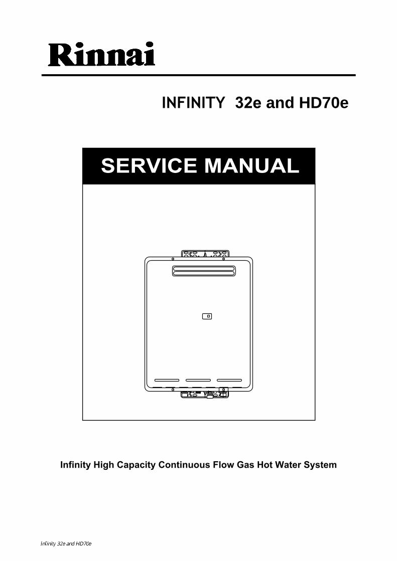
INFINITY 32e and HD70e
Infinity High Capacity Continuous Flow Gas Hot Water System
SERVICE MANUAL
The Rinnai Infinity 32e and Heavy Duty 70e water heater, when correctly installed, comply with the requirements of the United Kingdom Water Regula-tions / Byelaws (Scotland). These Products can be found listed in the Water Fittings and Materials Directory.
The Rinnai Infinity 32e water heater is CE Marked for UK and Ireland as allowed by Technigas of Belgium. Certificate number E0715/5344 ID number 0461BO0715 Date of Issue 14 July 2003
Quality System Standard ISO 9001 - 1994 The Design, Development, and Manufacture of Gas Water Heating Appliances done under Rinnai’s Quality Management System is certified under the Quality Management System Standard ISO 9001. Registration Number JQ0003D Registered since: February 1994 Certified by Japan Gas Appliances Inspection Association.
Produced by Rinnai Technical Services Department
August 2004 - Issue 1.
No portion or part of this manual may be copied without prior permission from Rinnai U.K.Rinnai U.K. reserves the right to make modifications and change specifications without notice.
Failure to comply with these instructions may result in serious personal injury or damage to the appliance.
This manual has been published by Rinnai U.K. Technical Services. While many individualshave contributed to this publication, it will be successful only if you - the reader and customer -find it useful. We would like to extend an invitation to users of this manual to make contact withus, as your feedback and suggestions are valuable resources for us to include as improvements.Rinnai are constantly working toward supply improved appliances as well as information, andspecifications may be subject to alteration at any time.
Issue No1
WARNING
ALL WIRING INSIDE THIS APPLIANCE MAY BE AT 230 VOLTS POTENTIAL
ALL SERVICE WORK MUST BE CARRIED OUT BY AN AUTHORISED PERSON.
DO NOT TEST FOR GAS ESCAPES WITH AN OPEN FLAME
Infinity REU-V3232W / HD250E REU-V3232WC - iii - Issue 1 - 8/09/03 ©Rinnai
Table of Contents
Glossary of Terms and Symbols ................................................................................ iv
1. Introduction ................................................................................................................ 1
2. Specifications ............................................................................................................. 2
3. Water Flow Rates and Pressures ................................................................................ 4
4. Dimensions ................................................................................................................ 7
5. Installation ................................................................................................................. 8
6. Remote Controls ........................................................................................................ 9
7. Cutaway Diagram .................................................................................................... 13
8. Operational Flow Chart ........................................................................................... 14
9. Operation Principles ................................................................................................ 16
10. Main Components .................................................................................................. 17
11. Time Charts ............................................................................................................ 18
12. Wiring Diagram ..................................................................................................... 19
13. Dip Switch Settings ............................................................................................... 20
14. Fault Finding .......................................................................................................... 22
15. Component Circuit Value Table ............................................................................ 25
16. Component and Circuit Checks ............................................................................. 26
17. Maintenance Monitor / Error History .................................................................... 37
18. Gas Pressure Setting Procedure ............................................................................. 39
19. Gas Conversion Procedure ..................................................................................... 41
20. Dismantling for Service ......................................................................................... 43
21. Exploded Diagram ................................................................................................. 49
22. Parts List ................................................................................................................ 53
SERVICE CONTACT POINTS ............................................................................... 57
Infinity REU-V3232W / HD250E REU-V3232WC - iv - Issue 1 - 8/09/03 ©Rinnai
Glossary of Terms and Symbols
dB(A) - sound pressure level in decibels, “A” range
DC - direct current
AC - alternating current
WFCD - water flow control device
FB - feedback information
FF - feedforward information
Hz - Hertz
IC - integrated circuit
kcal/h - kilocalorie per hour
kW - kilowatts
LED - light emitting diode
L/min - Litres per minute
mA - milliamps
mbar - millibars of pressure
mm - millimetres
bar - gauge pressure
OHS - overheat switch
PCB - printed circuit board
CPU - central processing unit
POT - potentiometer
rpm - revolutions per minute
SV - solenoid valve
ø - diameteroC - temperature rise above ambient
POV - modulating valve
TE - thermal efficiency
TH - thermistor
TIN - temperature of incoming water
TOUT - temperature of outgoing water
∆
Infinity REU-V3232W / HD250E REU-V3232WC - 1 - Issue 1 - 8/09/03 ©Rinnai
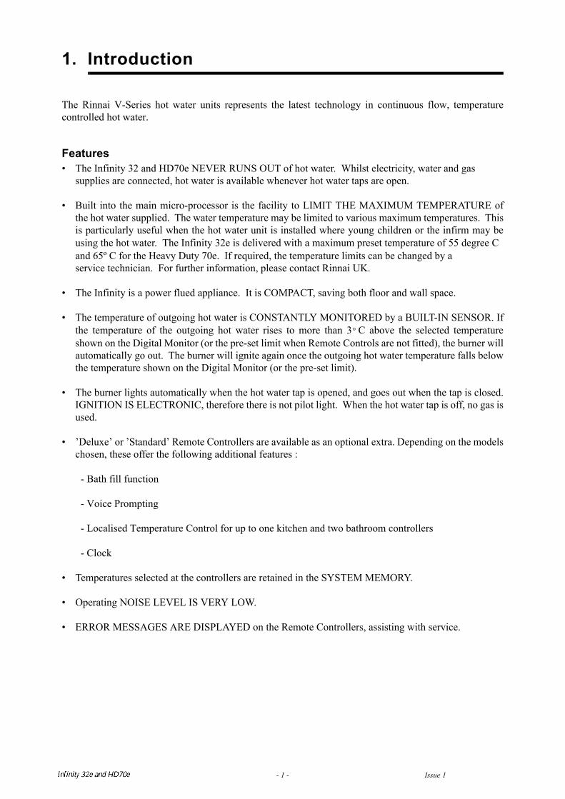
1. Introduction
The Rinnai V-Series hot water units represents the latest technology in continuous flow, temperaturecontrolled hot water.
Features• The Infinity 32 and HD70e NEVER RUNS OUT of hot water. Whilst electricity, water and gas
supplies are connected, hot water is available whenever hot water taps are open.
• Built into the main micro-processor is the facility to LIMIT THE MAXIMUM TEMPERATURE ofthe hot water supplied. The water temperature may be limited to various maximum temperatures. Thisis particularly useful when the hot water unit is installed where young children or the infirm may beusing the hot water. The Infinity 32e is delivered with a maximum preset temperature of 55 degree Cand 65º C for the Heavy Duty 70e. If required, the temperature limits can be changed by aservice technician. For further information, please contact Rinnai UK.
• The Infinity is a power flued appliance. It is COMPACT, saving both floor and wall space.
• The temperature of outgoing hot water is CONSTANTLY MONITORED by a BUILT-IN SENSOR. Ifthe temperature of the outgoing hot water rises to more than 3 C above the selected temperatureshown on the Digital Monitor (or the pre-set limit when Remote Controls are not fitted), the burner willautomatically go out. The burner will ignite again once the outgoing hot water temperature falls belowthe temperature shown on the Digital Monitor (or the pre-set limit).
• The burner lights automatically when the hot water tap is opened, and goes out when the tap is closed.IGNITION IS ELECTRONIC, therefore there is not pilot light. When the hot water tap is off, no gas isused.
• ’Deluxe’ or ’Standard’ Remote Controllers are available as an optional extra. Depending on the modelschosen, these offer the following additional features :
- Bath fill function
- Voice Prompting
- Localised Temperature Control for up to one kitchen and two bathroom controllers
- Clock
• Temperatures selected at the controllers are retained in the SYSTEM MEMORY.
• Operating NOISE LEVEL IS VERY LOW.
• ERROR MESSAGES ARE DISPLAYED on the Remote Controllers, assisting with service.
°
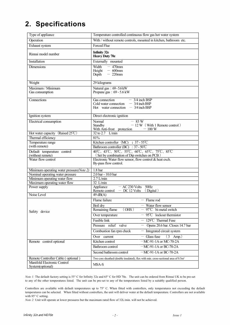
2. Specifications
Note 1: The default factory setting is 55° C for Infinity 32e and 65° C for HD 70e. The unit can be ordered from Rinnai UK to be pre-setto any of the other temperatures listed. The unit can be pre-set to any of the temperatures listed by a suitably qualified person. Controllers are available with default temperatures up to 75° C. When fitted with controllers, only temperatures not exceeding the defaulttemperatures can be selected. When fitted without controllers, the unit will deliver water at the default temperature. Controllers are not availablewith 85° C setting.Note 2: Unit will operate at lower pressures but the maximum rated flow of 32L/min. will not be achieved.
Type of appliance Temperature controlled continuous flow gas hot water system Operation With / without remote controls, mounted in kitchen, bathroom etc. Exhaust system Forced Flue
Rinnai model number Infinity 32eHeavy Duty 70e
Installation Externally mounted Dimensions Width - 470mm
Height - 600mm Depth - 220mm
Weight 29 kilograms Maximum / Minimum Gas consumption
Natural gas:69 - 5.6 kW Propane gas:69 - 5.6 kW
Connections Gas connection - 3/4 inch BSP Cold water connection - 3/4 inch BSP Hot water connection - 3/4 inch BSP
Ignition system Direct electronic ignition Electrical consumption Normal - 83 W
Standby - 12 W( With 1 Remote control ) With Anti-frost protection - 100 W
Hot water capacity(Raised 25) 32 to 2.7 L/min Thermal efficiency 81%
Kitchen controller(MC) : 37 - 55 Temperature range (with remote) Bathroom controller (BC) :37 - 50 Default temperature control (without remote)
40、43、50、55、60、65、75、85 ( Set by combination of Dip switches on PCB )
Water flow control Electronic Water flow sensor, flow control & heat exch. By-pass flow control.
Minimum operating water pressure(Note 2) 1.8 bar Nominal operating water pressure 2.0 bar - 10.0 bar Minimum operating water flow 2.7 L/min Maximum operating water flow 32 L/min Power supply Appliance - AC 230 Volts 50Hz
Remote control - DC 12 Volts ( Digital ) Noise Level 49 dB(A)
Flame failure - Flame rod Boil dry - Water flow sensor Remaining flame ( OHS ) - 97 bi-metal switch Over temperature - 95 lockout thermistor Fusible link - 129 Thermal Fuse Pressure relief valve - Opens 20.6 bar. Closes 14.7 bar Combustion fan rpm check - Integrated circuit system
Safety device
Over current - Glass fuse ( 3 Amp.) Kitchen control -MC-91-1A or MC-70-2A Bathroom control -MC-91-1A or BC-70-2A
Remote control optional
Second bathroom control -MC-91-1A or BC-70-2A Remote Controller Cable ( optional ) Two core sheathed (double insulated), flex with min. cross-sectional area of 0.5m² Manifold Electronic Control System(optional) MSA-S
Infinity REU-V3232W / HD250E REU-V3232WC - 2 - Issue 1 - 8/09/03 ©Rinnai
Sensors and Safety Devices
• Heat Exchanger Thermistor: Measures hot water temperature at heat exchanger outlet. If water temperature reaches a predetermined limit, gas supply is stopped.
• Hot Water Delivery Thermistor: Measures hot water temperature at the outlet valve (i.e. the ‘mixed’temperature).
• Flame Rod: Monitors combustion characteristics inside the combustion chamber. If the flame fails, gassupply is stopped.
• Overheat Switch: Situated on the heat exchanger, gas supply is stopped when water temperaturereaches 97 C for a number of seconds.
• Fusible Link: Situated on the heat exchanger, electrical power supply is stopped if the temperatureexceeds 129 C.
• Water Pressure Relief Valve: Safeguards the water circuit against excessive inlet pressure. Opens at21.0 bar, closes at 15.0 bar.
• Electrical Fuse: (3A glass fuse) prevents against over-current. Surge Protector: prevents against over-current.
• Boil Dry Prevention: If water flow sensor detects no flow, gas supply is stopped.
• Combustion Fan Speed Sensor: In case of combustion fan defect (no rotation of fan) gas supply isstopped.
• Temperature Cutout: If the delivered hot water temperature rises above the required delivery temperature for a number of seconds, the gas supply is stopped.
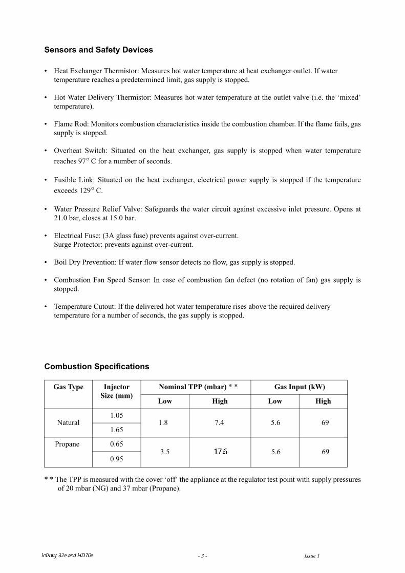
Combustion Specifications
* * The TPP is measured with the cover ‘off’ the appliance at the regulator test point with supply pressuresof 20 mbar (NG) and 37 mbar (Propane).
Gas Type Injector Size (mm)
Nominal TPP (mbar) * * Gas Input (kW)
Low High Low High
Natural1.05
1.8 7.4 5.6 691.65
Propane
0.65 3.5
5.6 69
0.95
°
°
Infinity REU-V3232W / HD250E REU-V3232WC - 3 - Issue 1 - 8/09/03 ©Rinnai
3. Water Flow Rates and Pressures
Table 1 shows unmixed and mixed water flow rates and approximate gas consumptions for varioustemperature rises. The unmixed flow rates are the flow rates available at the given temperature rise directlyat the outlet of the water heater. The mixed water flow rates are available at the given temperature rise bymixing hot water from the outlet of the water heater with cold water from the mains supply.
Water Flows can also be calculated by the following formula:
M = 60 x ( Q / C x T )
Where M = Water flow rate in litres/minute. If M is ≤ to 32, the water is unmixed, the entire flow goesthrough the water heater. If M > 32 the hot water from the unit is mixed with cold water.Q = Heat energy available in kW = 56kW for the Infinity 32e and 70eC = Specific heat of water = 4.2KJ/Kg C. This does not change for the purpose of this calculation.
T = Temperature rise required ( C)
Example:What is the flow rate available with an incoming water temperature of 10 C and a required temperature of20 C?
T = 20 - 10 = 10 CQ = 56C = 4.2
M = 60 x ( 56 / (4.2 x 10) ) = 80 l/min. Since 80 is greater than 32, this flow rate is mixed. This resultcorresponds with the value in Table 1.
∆
°∆ °
°°
∆ °
Infinity REU-V3232W / HD250E REU-V3232WC - 4 - Issue 1 - 8/09/03 ©Rinnai
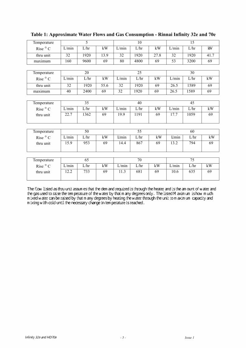
Table 1: Approximate Water Flows and Gas Consumption - Rinnai Infinity 32e and 70e
Temperature Rise C
5 10 15L/min L/hr kW L/min L/hr kW L/min L/hr kW
thru unit 32 1920 13.9 32 1920 27.8 32 1920 41.7maximum 160 9600 69 80 4800 69 53 3200 69
Temperature Rise C
20 25 30L/min L/hr kW L/min L/hr kW L/min L/hr kW
thru unit 32 1920 55.6 32 1920 69 26.5 1589 69maximum 40 2400 69 32 1920 69 26.5 1589 69
Temperature Rise Cthru unit
35 40 45L/min L/hr kW L/min L/hr kW L/min L/hr kW22.7 1362 69 19.9 1191 69 17.7 1059 69
Temperature Rise Cthru unit
50 55 60L/min L/hr k W L/min L/hr kW L/min L/hr kW15.9 953 69 14.4 867 69 13.2 794 69
Temperature Rise Cthru unit
65 70 75L/min L/hr kW L/min L/hr kW L/min L/hr kW12.2 733 69 11.3 681 69 10.6 635 69
Temperature Rise C
(unmixed and mixed)
80 85 90L/min L/hr MJ/hr L/min L/hr MJ/hr L/min L/hr MJ/hr
9.9 596.0 250.0 9.3 561.0 250.0 8.8 530.0 250.0
°
°
°
°
°
°
Infinity REU-V3232W / HD250E REU-V3232WC - 5 - Issue 1 - 8/09/03 ©Rinnai
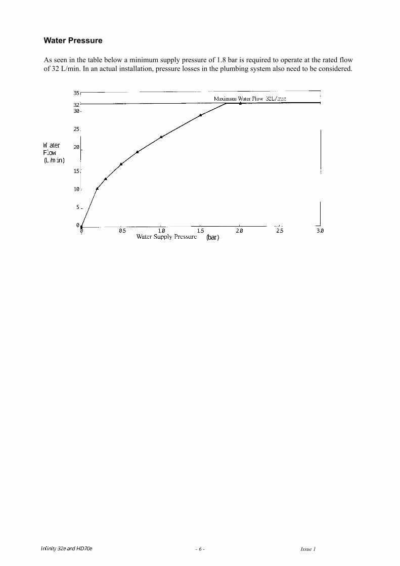
Water Pressure
As seen in the table below a minimum supply pressure of 1.8 bar is required to operate at the rated flowof 32 L/min. In an actual installation, pressure losses in the plumbing system also need to be considered.
Infinity REU-V3232W / HD250E REU-V3232WC - 6 - Issue 1 - 8/09/03 ©Rinnai
Infinity REU-V3232W / HD250E REU-V3232WC - 7 - Issue 1 - 8/09/03 ©Rinnai
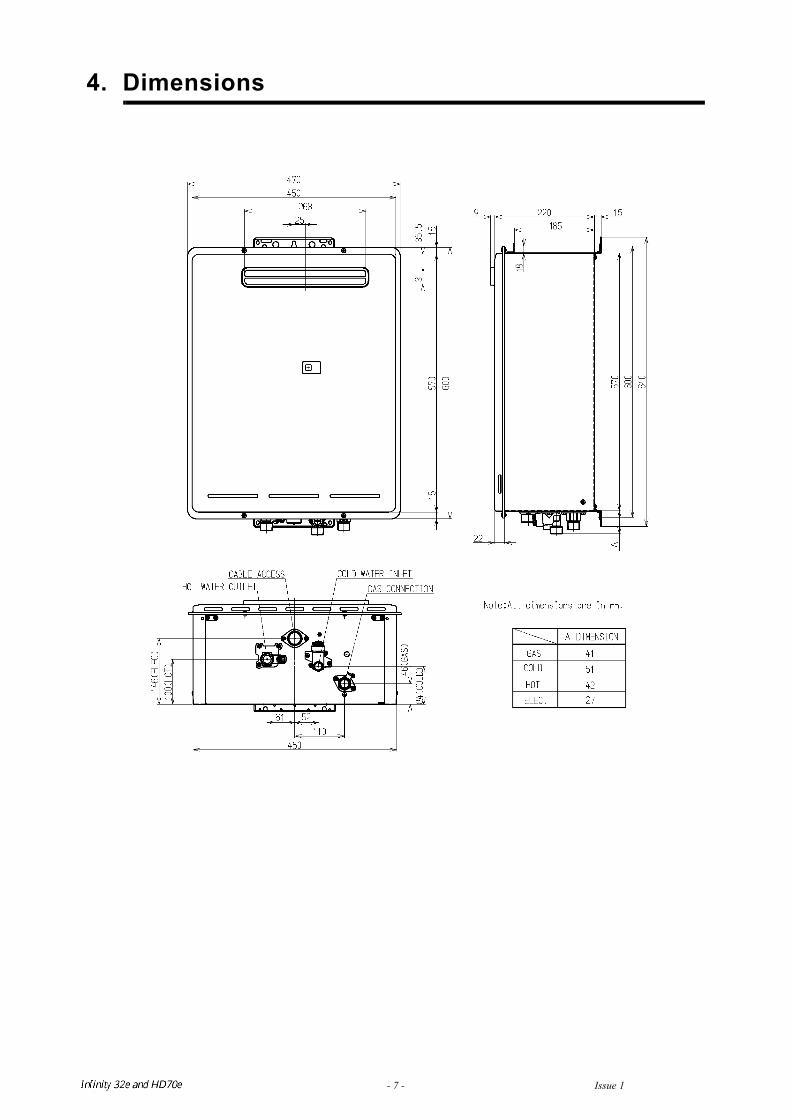
4. Dimensions
Infinity REU-V3232W / HD250E REU-V3232WC - 8 - Issue 1 - 8/09/03 ©Rinnai
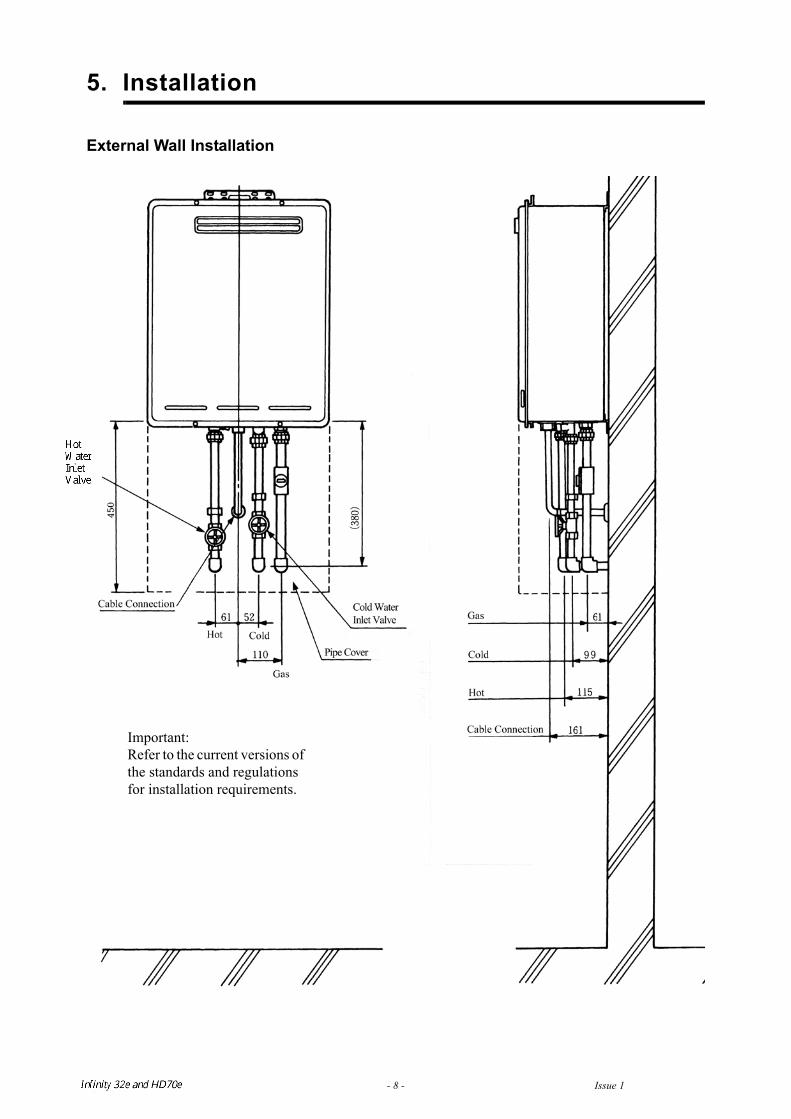
5. Installation
External Wall Installation
Important:Refer to the current versions of the standards and regulationsfor installation requirements.
120
90
20
MC-91-1A
195
97
22
BC-70-2A
6. Remote Controls
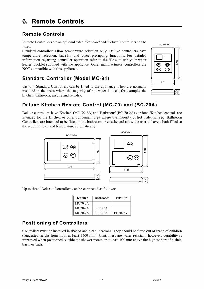
Remote ControlsRemote Controllers are an optional extra. 'Standard' and 'Deluxe' controllers can befitted.Standard controllers allow temperature selection only. Deluxe controllers havetemperature selection, bath-fill and voice prompting functions. For detailedinformation regarding controller operation refer to the 'How to use your waterheater' booklet supplied with the appliance. Other manufacturers' controllers areNOT compatible with this appliance.
Standard Controller (Model MC-91)Up to 4 Standard Controllers can be fitted to the appliance. They are normallyinstalled in the areas where the majority of hot water is used, for example, thekitchen, bathroom, ensuite and laundry.
Deluxe Kitchen Remote Control (MC-70) and (BC-70A)Deluxe controllers have 'Kitchen' (MC-70-2A) and 'Bathroom' (BC-70-2A) versions. 'Kitchen' controls areintended for the Kitchen or other convenient area where the majority of hot water is used. BathroomControllers are intended to be fitted in the bathroom or ensuite and allow the user to have a bath filled tothe required level and temperature automatically.
Up to three ‘Deluxe’ Controllers can be connected as follows:
Positioning of ControllersControllers must be installed in shaded and clean locations. They should be fitted out of reach of children(suggested height from floor at least 1500 mm). Controllers are water resistant, however, durability isimproved when positioned outside the shower recess or at least 400 mm above the highest part of a sink,basin or bath.
Kitchen Bathroom EnsuiteMC70-2AMC70-2A BC70-2AMC70-2A BC70-2A BC70-2A
Infinity REU-V3232W /HD250E REU-V3232WC - 9 - Issue 1 - 8/09/03 ©Rinnai
:
Do not install the Controllers• Near a heat source, such as a cook top, stove or oven. Heat, steam smoke and hot oil may
cause damage.
• In direct sunlight.
• Outdoors unless an enclosure is provided which protects the controller against sunlight and dust ingress.
• Against a metal wall unless the wall is earthed in accordance with current regulations.
Remote Controller ConnectionRemote controls operate at extra low voltage (12 Volts DC) which is supplied from the appliance.Controllers are supplied with 15 m of electrical cable. The cable wires for connection to the appliance arefitted with spade terminals.
Extension cables are available from Rinnai. Alternatively, a two core sheathed (double insulated) flex withminimum cross-sectional area of 0.5 mm² can be used. Maximum cable length is 50 m.
For connection refer to the “CONNECTING REMOTE CONTROL CABLES” section.
Water Heater and Controller installation configurations
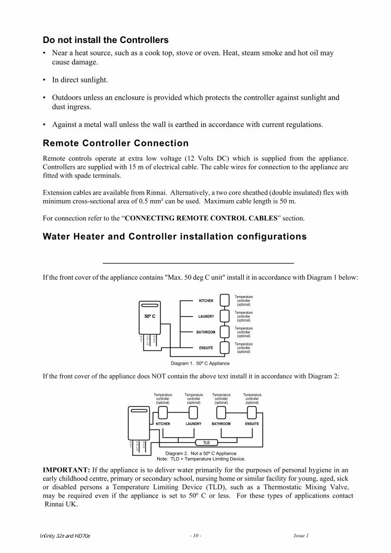
If the front cover of the appliance contains "Max. 50 deg C unit" install it in accordance with Diagram 1 below
If the front cover of the appliance does NOT contain the above text install it in accordance with Diagram 2:
IMPORTANT: If the appliance is to deliver water primarily for the purposes of personal hygiene in anearly childhood centre, primary or secondary school, nursing home or similar facility for young, aged, sickor disabled persons a Temperature Limiting Device (TLD), such as a Thermostatic Mixing Valve,may be required even if the appliance is set to 50º C or less. For these types of applications contact Rinnai UK.
50º C
KITCHENTemperature
controller(optional)
Temperaturecontroller(optional)
Temperaturecontroller(optional)
Temperaturecontroller(optional)
LAUNDRY
BATHROOM
ENSUITE
HOT
COLD
GAS
Diagram 1. 50º C Appliance
KITCHEN
Temperaturecontroller(optional)
Temperaturecontroller(optional)
LAUNDRY BATHROOM
Temperaturecontroller(optional)
Temperaturecontroller(optional)
ENSUITE
TLDHOT
COLD
GAS
Diagram 2. Not a 50º C ApplianceNote: TLD = Temperature Limiting Device.
Infinity REU-V3232W /HD250E REU-V3232WC - 10 - Issue 1 - 8/09/03 ©Rinnai
Connecting Remote Control CablesDo not attempt to connect the remote control cable terminals to the appliance with the power on.
RISK OF ELECTRICAL SHOCK !
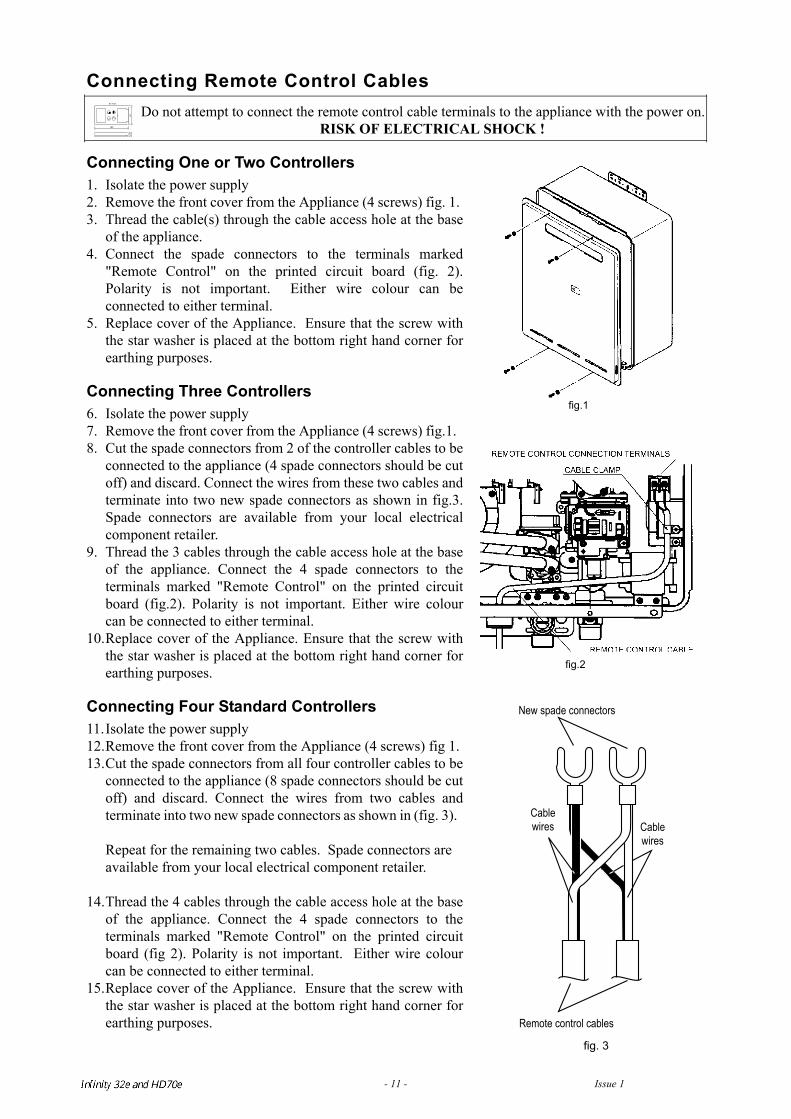
Connecting One or Two Controllers1. Isolate the power supply2. Remove the front cover from the Appliance (4 screws) fig. 1. 3. Thread the cable(s) through the cable access hole at the base
of the appliance.4. Connect the spade connectors to the terminals marked
"Remote Control" on the printed circuit board (fig. 2).Polarity is not important. Either wire colour can beconnected to either terminal.
5. Replace cover of the Appliance. Ensure that the screw withthe star washer is placed at the bottom right hand corner forearthing purposes.
Connecting Three Controllers6. Isolate the power supply7. Remove the front cover from the Appliance (4 screws) fig.1. 8. Cut the spade connectors from 2 of the controller cables to be
connected to the appliance (4 spade connectors should be cutoff) and discard. Connect the wires from these two cables andterminate into two new spade connectors as shown in fig.3.Spade connectors are available from your local electricalcomponent retailer.
9. Thread the 3 cables through the cable access hole at the baseof the appliance. Connect the 4 spade connectors to theterminals marked "Remote Control" on the printed circuitboard (fig.2). Polarity is not important. Either wire colourcan be connected to either terminal.
10.Replace cover of the Appliance. Ensure that the screw withthe star washer is placed at the bottom right hand corner forearthing purposes.
Connecting Four Standard Controllers11.Isolate the power supply12.Remove the front cover from the Appliance (4 screws) fig 1. 13.Cut the spade connectors from all four controller cables to be
connected to the appliance (8 spade connectors should be cutoff) and discard. Connect the wires from two cables andterminate into two new spade connectors as shown in (fig. 3).
Repeat for the remaining two cables. Spade connectors are available from your local electrical component retailer.
14.Thread the 4 cables through the cable access hole at the baseof the appliance. Connect the 4 spade connectors to theterminals marked "Remote Control" on the printed circuitboard (fig 2). Polarity is not important. Either wire colourcan be connected to either terminal.
15.Replace cover of the Appliance. Ensure that the screw withthe star washer is placed at the bottom right hand corner forearthing purposes.
fig.1
fig.2
fig. 3
New spade connectors
Cablewires Cable
wires
Remote control cables
19597
22
BC-70-2A
Infinity REU-V3232W /HD250E REU-V3232WC - 11 - Issue 1 - 8/09/03 ©Rinnai
MC-91A Controller Programming
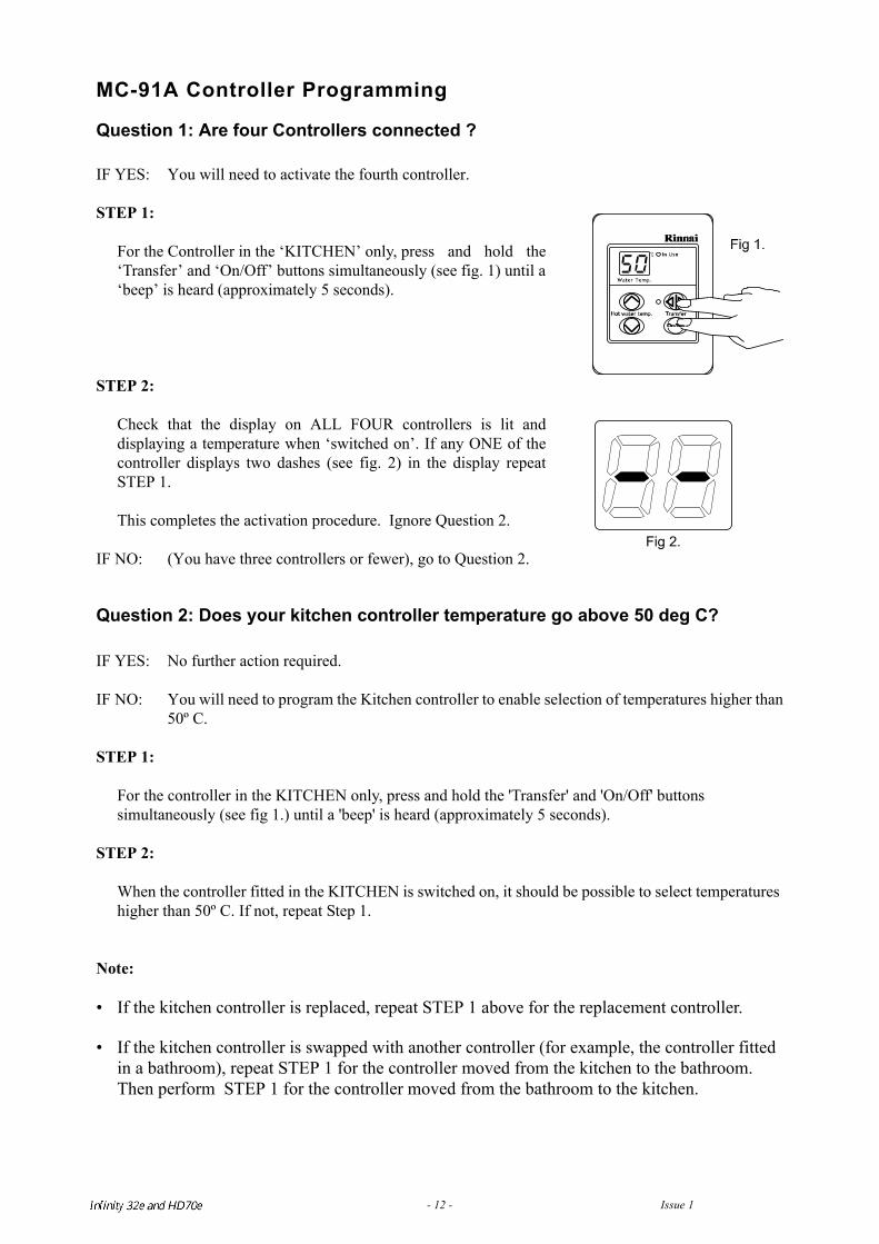
Question 1: Are four Controllers connected ?
IF YES: You will need to activate the fourth controller.
STEP 1:
For the Controller in the ‘KITCHEN’ only, press and hold the‘Transfer’ and ‘On/Off’ buttons simultaneously (see fig. 1) until a‘beep’ is heard (approximately 5 seconds).
STEP 2:
Check that the display on ALL FOUR controllers is lit anddisplaying a temperature when ‘switched on’. If any ONE of thecontroller displays two dashes (see fig. 2) in the display repeatSTEP 1.
This completes the activation procedure. Ignore Question 2.
IF NO: (You have three controllers or fewer), go to Question 2.
Question 2: Does your kitchen controller temperature go above 50 deg C? IF YES: No further action required.
IF NO: You will need to program the Kitchen controller to enable selection of temperatures higher than50º C.
STEP 1:
For the controller in the KITCHEN only, press and hold the 'Transfer' and 'On/Off' buttons simultaneously (see fig 1.) until a 'beep' is heard (approximately 5 seconds).
STEP 2:
When the controller fitted in the KITCHEN is switched on, it should be possible to select temperatures higher than 50º C. If not, repeat Step 1.
Note:
• If the kitchen controller is replaced, repeat STEP 1 above for the replacement controller.
• If the kitchen controller is swapped with another controller (for example, the controller fitted in a bathroom), repeat STEP 1 for the controller moved from the kitchen to the bathroom. Then perform STEP 1 for the controller moved from the bathroom to the kitchen.
Fig 2.
Infinity REU-V3232W /HD250E REU-V3232WC - 12 - Issue 1 - 8/09/03 ©Rinnai
Infinity REU-V3232W /HD250E REU-V3232WC - 13 - Issue 1 - 8/09/03 ©Rinnai
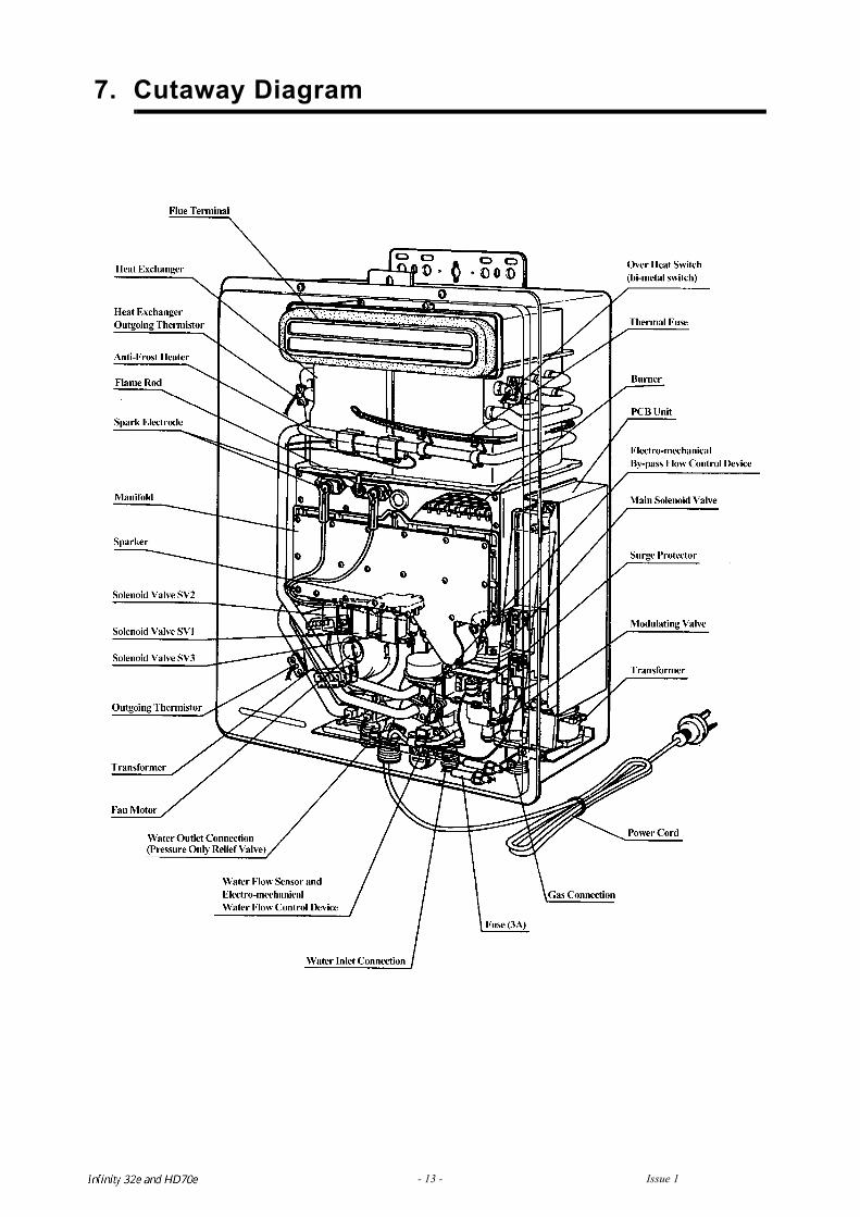
7. Cutaway Diagram
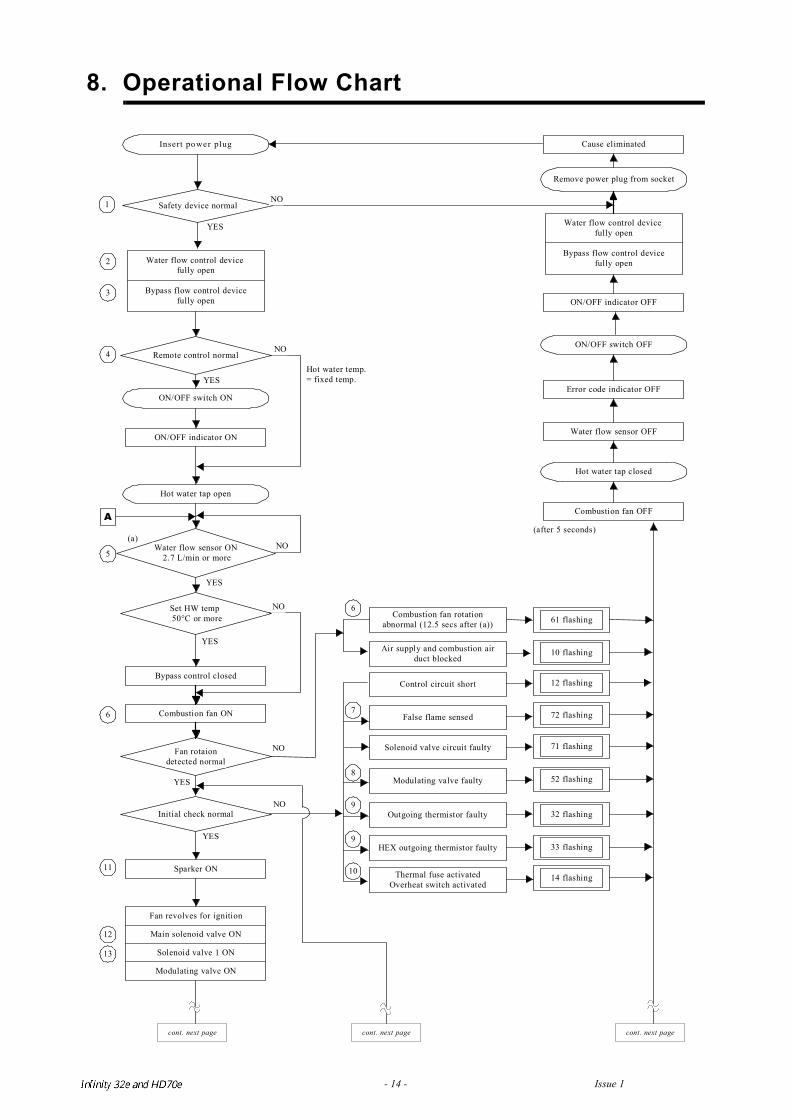
8. Operational Flow Chart
Bypass flow control devicefully open
Insert power plug
Safety device normal
ON/OFF switch ON
Remote control normal
ON/OFF indicator ON
Hot water tap open
Water flow sensor ON 2.7 L/min or more
Set HW temp 50°C or more
Bypass control closed
Combustion fan ON
Fan rotaiondetected normal
Initial check normal
Sparker ON
Water flow control device fully open
YES
YES
NO
YES
NO
Fan revolves for ignition
Main solenoid valve ON
Solenoid valve 1 ON
Modulating valve ON
Cause eliminated
Remove power plug from socket
Water flow control device fully open
Bypass flow control devicefully open
ON/OFF indicator OFF
ON/OFF switch OFF
Error code indicator OFF
Water flow sensor OFF
Hot water tap closed
Combustion fan OFF
(after 5 seconds)
1
2
3
4
5
(a)
6
11
12
13
A
Control circuit short
False flame sensed
Solenoid valve circuit faulty
Modulating valve faulty
Outgoing thermistor faulty
HEX outgoing thermistor faulty
Thermal fuse activatedOverheat switch activated
Combustion fan rotationabnormal (12.5 secs after (a))
Air supply and combustion airduct blocked
61 flashing
10 flashing
12 flashing
72 flashing
71 flashing
52 flashing
32 flashing
33 flashing
14 flashing
6
7
8
9
9
10
Hot water temp.= fixed temp.YES
NO
NO
YES
NO
NO
cont. next pagecont. next page cont. next page
YES
Infinity REU-V3232W /HD250E REU-V3232WC - 14 - Issue 1 - 8/09/03 ©Rinnai
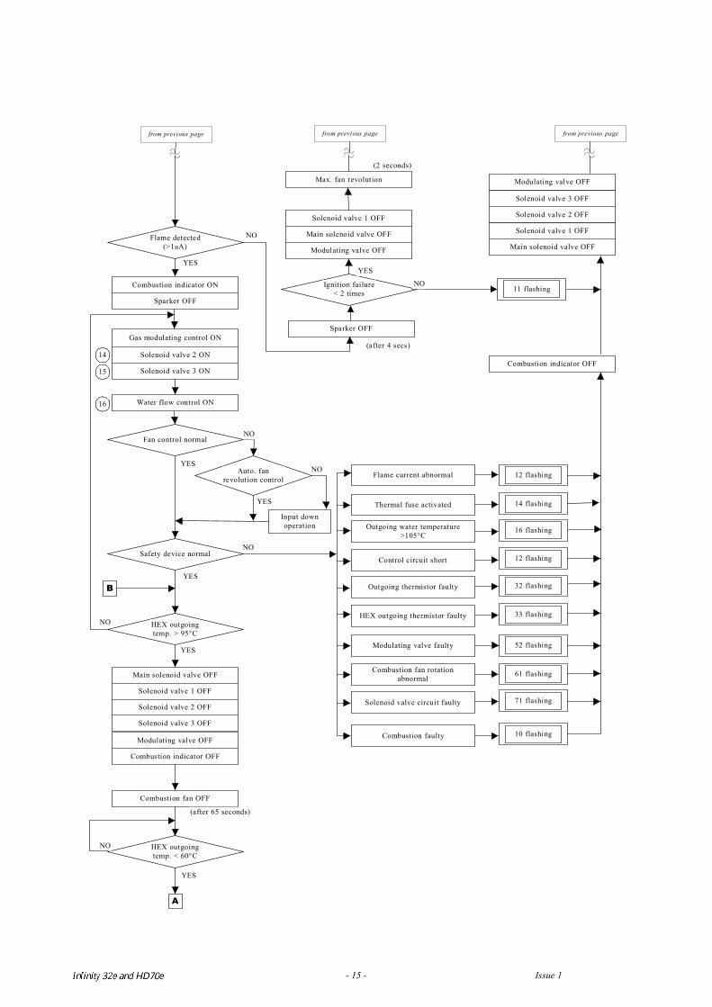
A
12 flashing
14 flashing
16 flashing
12 flashing
32 flashing
33 flashing
52 flashing
61 flashing
71 flashing
10 flashing
Flame detected(>1uA)
Combustion indicator ON
Sparker OFF
Gas modulating control ON
Solenoid valve 2 ON
Solenoid valve 3 ON
Water flow control ON
Fan control normal
Auto. fanrevolution control
Input downoperation
Safety device normal
HEX outgoingtemp. > 95°C
Main solenoid valve OFF
Solenoid valve 1 OFF
Solenoid valve 2 OFF
Solenoid valve 3 OFF
Modulating valve OFF
Combustion indicator OFF
Combustion fan OFF
HEX outgoingtemp. < 60°C
(after 65 seconds)
NO
YES
YES
NO
YES
YES
NO
Max. fan revolution
(2 seconds)
Solenoid valve 1 OFF
Main solenoid valve OFF
Modulating valve OFF
Ignition failure< 2 times
Sparker OFF
(after 4 secs)
Modulating valve OFF
Solenoid valve 3 OFF
Solenoid valve 2 OFF
Solenoid valve 1 OFF
Main solenoid valve OFF
11 flashing
Flame current abnormal
Thermal fuse activated
Outgoing water temperature>105°C
Control circuit short
Outgoing thermistor faulty
HEX outgoing thermistor faulty
Modulating valve faulty
Combustion fan rotationabnormal
Solenoid valve circuit faulty
Combustion faulty
Combustion indicator OFF
B
NO
YES
NO
14
15
16
from previous page from previous page from previous page
YES
NO
NO
YES
Infinity REU-V3232W /HD250E REU-V3232WC - 15 - Issue 1 - 8/09/03 ©Rinnai
Infinity REU-V3232W /HD250E REU-V3232WC - 16 - Issue 1 - 8/09/03 ©Rinnai
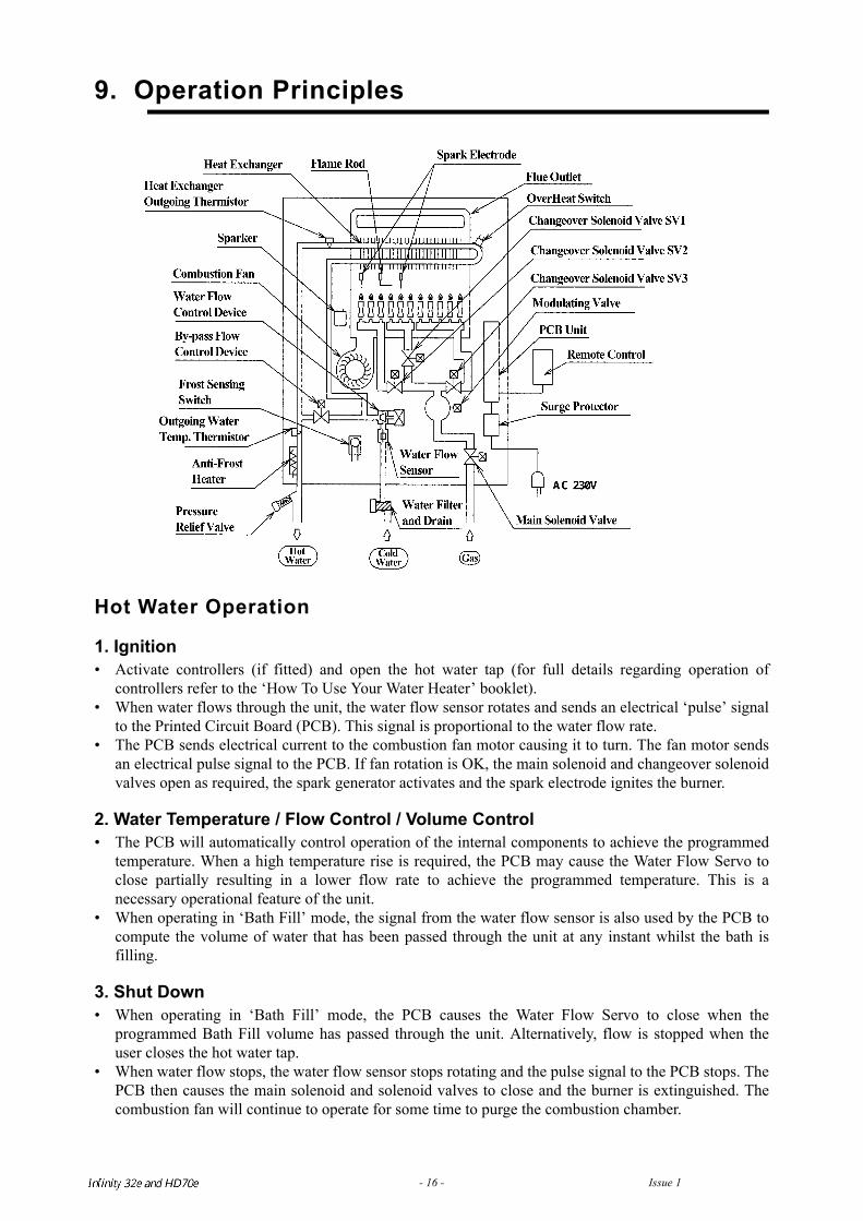
9. Operation Principles
Hot Water Operation
1. Ignition• Activate controllers (if fitted) and open the hot water tap (for full details regarding operation of
controllers refer to the ‘How To Use Your Water Heater’ booklet).• When water flows through the unit, the water flow sensor rotates and sends an electrical ‘pulse’ signal
to the Printed Circuit Board (PCB). This signal is proportional to the water flow rate.• The PCB sends electrical current to the combustion fan motor causing it to turn. The fan motor sends
an electrical pulse signal to the PCB. If fan rotation is OK, the main solenoid and changeover solenoidvalves open as required, the spark generator activates and the spark electrode ignites the burner.
2. Water Temperature / Flow Control / Volume Control• The PCB will automatically control operation of the internal components to achieve the programmed
temperature. When a high temperature rise is required, the PCB may cause the Water Flow Servo toclose partially resulting in a lower flow rate to achieve the programmed temperature. This is anecessary operational feature of the unit.
• When operating in ‘Bath Fill’ mode, the signal from the water flow sensor is also used by the PCB tocompute the volume of water that has been passed through the unit at any instant whilst the bath isfilling.
3. Shut Down• When operating in ‘Bath Fill’ mode, the PCB causes the Water Flow Servo to close when the
programmed Bath Fill volume has passed through the unit. Alternatively, flow is stopped when theuser closes the hot water tap.
• When water flow stops, the water flow sensor stops rotating and the pulse signal to the PCB stops. ThePCB then causes the main solenoid and solenoid valves to close and the burner is extinguished. Thecombustion fan will continue to operate for some time to purge the combustion chamber.
Infinity REU-V3232W /HD250E REU-V3232WC - 17 - Issue 1 - 8/09/03 ©Rinnai
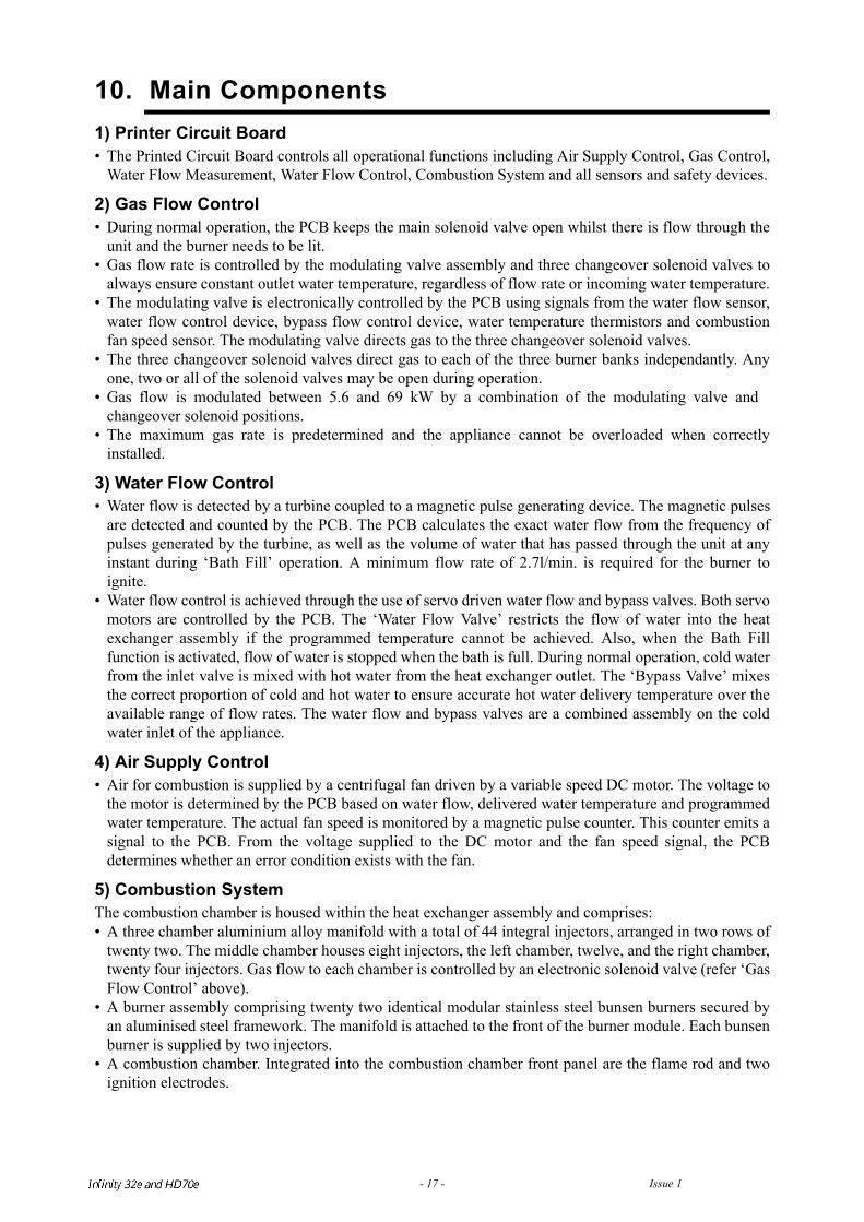
10. Main Components1) Printer Circuit Board• The Printed Circuit Board controls all operational functions including Air Supply Control, Gas Control,
Water Flow Measurement, Water Flow Control, Combustion System and all sensors and safety devices.
2) Gas Flow Control• During normal operation, the PCB keeps the main solenoid valve open whilst there is flow through the
unit and the burner needs to be lit.• Gas flow rate is controlled by the modulating valve assembly and three changeover solenoid valves to
always ensure constant outlet water temperature, regardless of flow rate or incoming water temperature.• The modulating valve is electronically controlled by the PCB using signals from the water flow sensor,
water flow control device, bypass flow control device, water temperature thermistors and combustionfan speed sensor. The modulating valve directs gas to the three changeover solenoid valves.
• The three changeover solenoid valves direct gas to each of the three burner banks independantly. Anyone, two or all of the solenoid valves may be open during operation.
• Gas flow is modulated between 5.6 and 69 kW by a combination of the modulating valve andchangeover solenoid positions.
• The maximum gas rate is predetermined and the appliance cannot be overloaded when correctlyinstalled.
3) Water Flow Control• Water flow is detected by a turbine coupled to a magnetic pulse generating device. The magnetic pulses
are detected and counted by the PCB. The PCB calculates the exact water flow from the frequency ofpulses generated by the turbine, as well as the volume of water that has passed through the unit at anyinstant during ‘Bath Fill’ operation. A minimum flow rate of 2.7l/min. is required for the burner toignite.
• Water flow control is achieved through the use of servo driven water flow and bypass valves. Both servomotors are controlled by the PCB. The ‘Water Flow Valve’ restricts the flow of water into the heatexchanger assembly if the programmed temperature cannot be achieved. Also, when the Bath Fillfunction is activated, flow of water is stopped when the bath is full. During normal operation, cold waterfrom the inlet valve is mixed with hot water from the heat exchanger outlet. The ‘Bypass Valve’ mixesthe correct proportion of cold and hot water to ensure accurate hot water delivery temperature over theavailable range of flow rates. The water flow and bypass valves are a combined assembly on the coldwater inlet of the appliance.
4) Air Supply Control• Air for combustion is supplied by a centrifugal fan driven by a variable speed DC motor. The voltage to
the motor is determined by the PCB based on water flow, delivered water temperature and programmedwater temperature. The actual fan speed is monitored by a magnetic pulse counter. This counter emits asignal to the PCB. From the voltage supplied to the DC motor and the fan speed signal, the PCBdetermines whether an error condition exists with the fan.
5) Combustion SystemThe combustion chamber is housed within the heat exchanger assembly and comprises:• A three chamber aluminium alloy manifold with a total of 44 integral injectors, arranged in two rows of
twenty two. The middle chamber houses eight injectors, the left chamber, twelve, and the right chamber,twenty four injectors. Gas flow to each chamber is controlled by an electronic solenoid valve (refer ‘GasFlow Control’ above).
• A burner assembly comprising twenty two identical modular stainless steel bunsen burners secured byan aluminised steel framework. The manifold is attached to the front of the burner module. Each bunsenburner is supplied by two injectors.
• A combustion chamber. Integrated into the combustion chamber front panel are the flame rod and twoignition electrodes.
Infinity REU-V3232W /HD250E REU-V3232WC - 18 - Issue 1 - 8/09/03 ©Rinnai
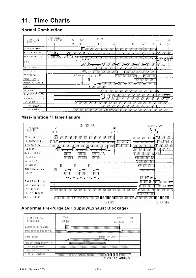
11. Time ChartsNormal Combustion
Miss-Ignition / Flame Failure
Abnormal Pre-Purge (AIr Supply/Exhaust Blockage)
Infinity REU-V3232W /HD250E REU-V3232WC - 19 - Issue 1 - 8/09/03 ©Rinnai
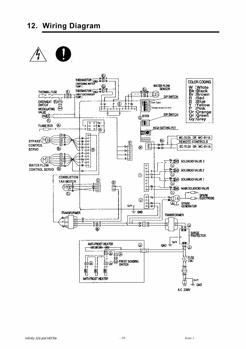
12. Wiring Diagram
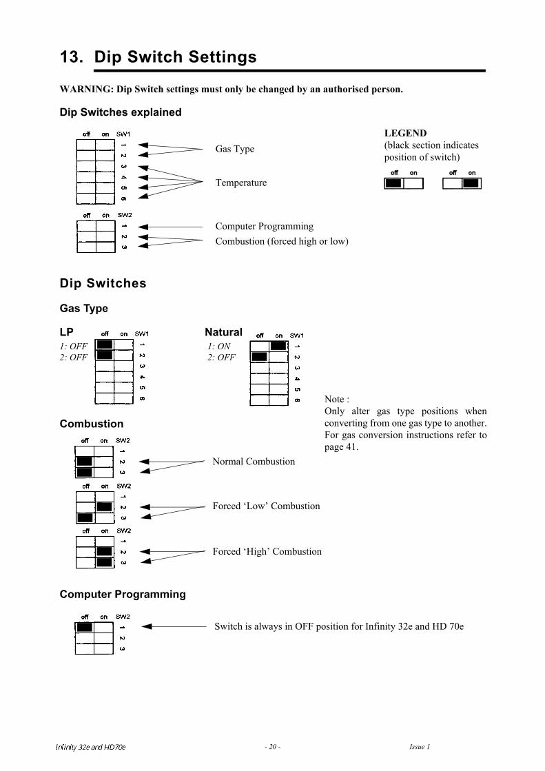
13. Dip Switch Settings
WARNING: Dip Switch settings must only be changed by an authorised person.
Dip Switches explained
Dip Switches
Gas Type
LP Natural1: OFF 1: ON2: OFF 2: OFF
Combustion
Computer Programming
Gas Type
Temperature
Computer ProgrammingCombustion (forced high or low)
LEGEND(black section indicates position of switch)
Normal Combustion
Forced ‘Low’ Combustion
Forced ‘High’ Combustion
Switch is always in OFF position for Infinity 32e and HD 70e
Note : Only alter gas type positions whenconverting from one gas type to another.For gas conversion instructions refer topage 41.
Infinity REU-V3232W /HD250E REU-V3232WC - 20 - Issue 1 - 8/09/03 ©Rinnai
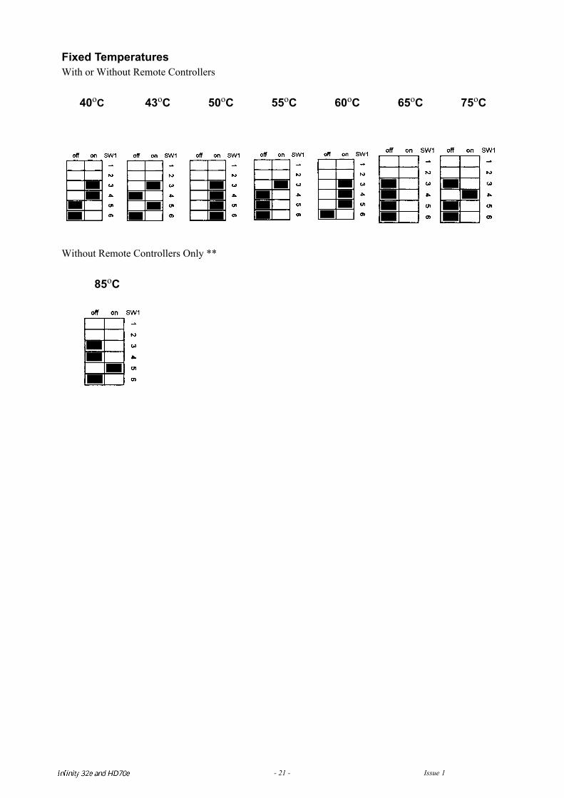
Fixed TemperaturesWith or Without Remote Controllers
Without Remote Controllers Only **
DO NOT attempt to set a temperature of 95° C unless the heater is marked as an 95° C unit.Such markings appear near the data plate, located on the burner cover and or on the bypass servo wiringloom. A unit set to between 40° C and 85° C MUST BE returned to Rinnai and specifically modified todeliver 95° C.
40oC 43oC 50oC 55oCFactory preset
(V3232W)
60oC 65oCFactory preset(V3232WC)
75oC
85oC 95oC
Infinity REU-V3232W /HD250E REU-V3232WC - 21 - Issue 1 - 8/09/03 ©Rinnai
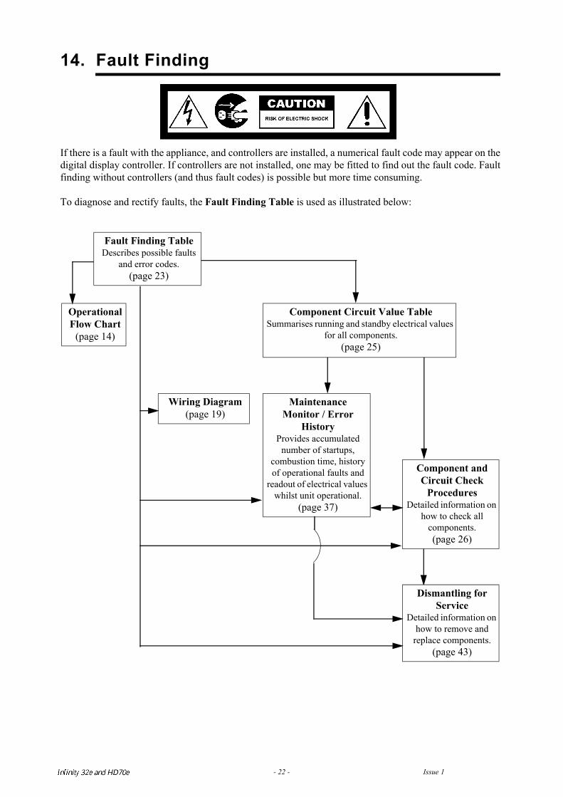
14. Fault Finding
If there is a fault with the appliance, and controllers are installed, a numerical fault code may appear on thedigital display controller. If controllers are not installed, one may be fitted to find out the fault code. Faultfinding without controllers (and thus fault codes) is possible but more time consuming.
To diagnose and rectify faults, the Fault Finding Table is used as illustrated below:
Fault Finding TableDescribes possible faults
and error codes. (page 23)
Operational Flow Chart
(page 14)
Component Circuit Value TableSummarises running and standby electrical values
for all components. (page 25)
Wiring Diagram(page 19)
MaintenanceMonitor / Error
HistoryProvides accumulated
number of startups, combustion time, history of operational faults and
readout of electrical values whilst unit operational.
(page 37)
Component and Circuit Check
ProceduresDetailed information on
how to check all components.(page 26)
Dismantling for Service
Detailed information on how to remove and
replace components.(page 43)
Infinity REU-V3232W /HD250E REU-V3232WC - 22 - Issue 1 - 8/09/03 ©Rinnai
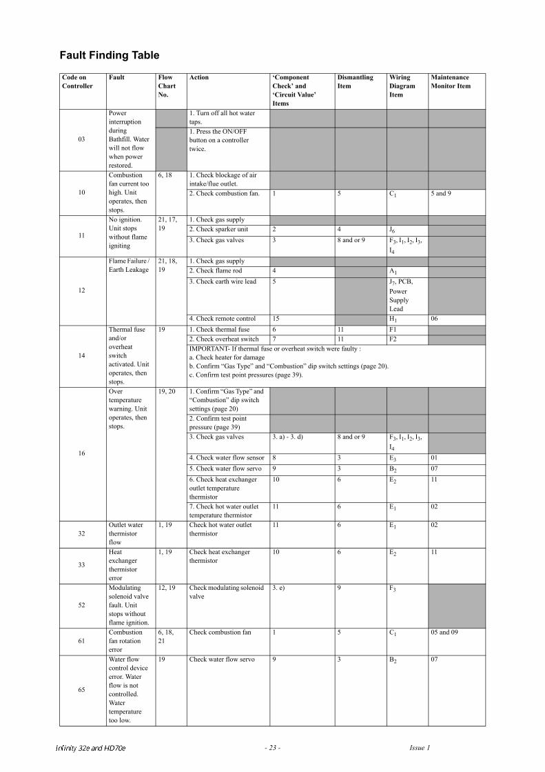
Fault Finding Table
Code on Controller
Fault Flow Chart No.
Action ‘Component Check’ and ‘Circuit Value’ Items
Dismantling Item
Wiring Diagram Item
Maintenance Monitor Item
03
Power interruption during Bathfill. Water will not flow when power restored.
1. Turn off all hot water taps.1. Press the ON/OFF button on a controller twice.
10
Combustion fan current too high. Unit operates, then stops.
6, 18 1. Check blockage of air intake/flue outlet.2. Check combustion fan. 1 5 C1 5 and 9
11
No ignition. Unit stops without flame igniting
21, 17, 19
1. Check gas supply2. Check sparker unit 2 4 J6
3. Check gas valves 3 8 and or 9 F3, I1, I2, I3, I4
12
Flame Failure / Earth Leakage
21, 18, 19
1. Check gas supply2. Check flame rod 4 A1
3. Check earth wire lead 5 J7, PCB, Power Supply Lead
4. Check remote control 15 H1 06
14
Thermal fuse and/or overheat switch activated. Unit operates, then stops.
19 1. Check thermal fuse 6 11 F12. Check overheat switch 7 11 F2IMPORTANT- If thermal fuse or overheat switch were faulty :a. Check heater for damageb. Confirm “Gas Type” and “Combustion” dip switch settings (page 20).c. Confirm test point pressures (page 39).
16
Over temperature warning. Unit operates, then stops.
19, 20 1. Confirm “Gas Type” and “Combustion” dip switch settings (page 20)2. Confirm test point pressure (page 39)3. Check gas valves 3. a) - 3. d) 8 and or 9 F3, I1, I2, I3,
I4
4. Check water flow sensor 8 3 E3 015. Check water flow servo 9 3 B2 076. Check heat exchanger outlet temperature thermistor
10 6 E2 11
7. Check hot water outlet temperature thermistor
11 6 E1 02
32 Outlet water thermistor flow
1, 19 Check hot water outlet thermistor
11 6 E1 02
33
Heat exchanger thermistor error
1, 19 Check heat exchanger thermistor
10 6 E2 11
52
Modulating solenoid valve fault. Unit stops without flame ignition.
12, 19 Check modulating solenoid valve
3. e) 9 F3
61Combustion fan rotation error
6, 18, 21
Check combustion fan 1 5 C1 05 and 09
65
Water flow control device error. Water flow is not controlled. Water temperature too low.
19 Check water flow servo 9 3 B2 07
Infinity REU-V3232W /HD250E REU-V3232WC - 23 - Issue 1 - 8/09/03 ©Rinnai
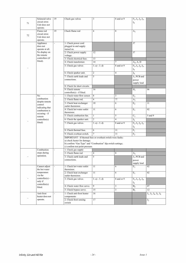
71
Solenoid valve circuit error. Unit does not operate.
19 Check gas valves 3 8 and or 9 F3, I1, I2, I3, I4
72
Flame rod circuit error. Unit does not operate.
19 Check flame rod 4 8 A1
-
Appliance does not operate at all. No display on the remote controllers (if fitted).
- 1. Check power cord plugged in and supply turned on.
J7
2. Check power supply voltage.
12 J7
3. Check electrical fuse. 134. Check transformer. 14 7 A2, A, D5. Check gas valves 3. a) - 3. d) 8 and or 9 F3, I1, I2, I3,
I4
6. Check sparker unit. 2 4 J6
7. Check earth leads and connections.
5 J7, PCB and power supply lead
8. Check for short circuits.9. Check remote controller(s) - if fitted.
16 H1 06
-
No combustion despite remote control indicating that combustion is occuring - if remote controller(s) fitted)
- 1. Check water flow sensor. 8 3 E3
2. Check flame rod. 4 ?? A1
3. Check heat exchanger outlet thermistor.
10 6 E2 11
4. Check hot water outlet thermistor.
11 6 E1 02
5. Check combustion fan. 1 5 C1 5 and 96. Check the sparker unit. 2 4 J6
7. Check gas valves. 3. a) - 3. d) 8 and or 9 F3, I1, I2, I3, I4
8. Check thermal fuse. 6 11 F1
9. Check overheat switch. 7 11 F2
IMPORTANT - If thermal fuse or overheat switch were faulty:a) check heater for damage;b) confirm “Gas Type” and “Combustion” dip switch settings;c) confirm test point pressure.
-
Combustion stops during operation.
- 1. Check gas supply2. Check flame rod 4 8 A1
3. Check earth leads and connections.
5 J7, PCB and power supply lead
-
Cannot adjust the hot water temperature via the controller(s) - only if controller(s) fitted.
- 1. Check hot water outlet thermistor.
11 6 E1 02
2. Check heat exchanger outlet thermistor.
11 6 E1 02
3. Check gas valves 3. a) - 3. d) 8 and or 9 F3, I1, I2, I3, I4
4. Check water flow servo. 9 3 B2 075. Check bypass servo. 15 3 B1 12
-
Anti-frost heater does not operate.
- 1. Check anti-frost heater components
16 J1, J3, J4, J5, J8
2. Check frost sensing switch
17 J2
Infinity REU-V3232W /HD250E REU-V3232WC - 24 - Issue 1 - 8/09/03 ©Rinnai
Infinity REU-V3232W /HD250E REU-V3232WC - 25 - Issue 1 - 8/09/03 ©Rinnai
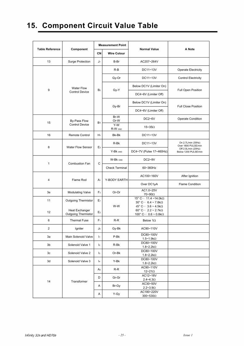
15. Component Circuit Value Table
CN Wire Colour
13 Surge Protection J7 B-Br AC207~264V
R-B DC11~13V Operate Electricity
Gy-Or DC11~13V Control Electricity
Below DC1V (Limiter On)
DC4~6V (Limiter Off)
Below DC1V (Limiter On)
DC4~6V (Limiter Off)
Br-W
Or-WDC2~6V Operate Condition
Y-W
R-W GND15~35
16 Remote Control H1 Bk-Bk DC11~13V
R-Bk DC11~13V
Y-Bk GND DC4~7V (Pulse 17~460Hz)
W-Bk GND DC2~9V
Check Terminal 60~360Hz
AC100~160V After Ignition
Over DC1µA Flame Condition
3e Modulating Valve F3 Or-OrAC1.0~25V
70~90
11 Outgoing Thermistor E1
12Heat Exchanger
Outgoing ThermistorE2
6 Thermal Fuse F1 R-R Below 1
2 Igniter J6 Gy-Bk AC90~110V
3a Main Solenoid Valve I1 P-BkDC80~100V
1.5~1.9k
3b Solenoid Valve 1 I2 R-BkDC80~100V
1.8~2.2k
3c Solenoid Valve 2 I3 Or-BkDC80~100V
1.8~2.2k
3d Solenoid Valve 3 I4 Y-BkDC80~100V
1.8~2.2k
A2 R-RAC90~110V
12~21
D Gr-GrAC12~18V
2.4~4.3
A Br-GyAC30~50V
2.2~3.9
A Y-GyAC180~220V
300~530
Table Reference Component
C1
Water Flow Sensor E3
15
8
Normal Value A Note
Water Flow
Control DeviceB2
Gy-Br
Gy-Y Full Open Position
Full Close Position
Measurement Point
On 2.7L/min (30Hz)
Over 1800 PULSE/min
Off 2.0L/min (20Hz)
Below 1200 PULSE/min
By-Pass Flow
Control DeviceB1
A1
Combustion Fan
Y-BODY EARTH4
9
Flame Rod
Transformer14
15° C··· 11.4 ~14.0k
30° C··· 6.4 ~ 7.8k
5° C··· 3.6 ~ 4.5k
60° C··· 2.2 ~ 2.7k
100° C··· 0.6 ~ 0.8k
W-W
16. Component and Circuit Checks
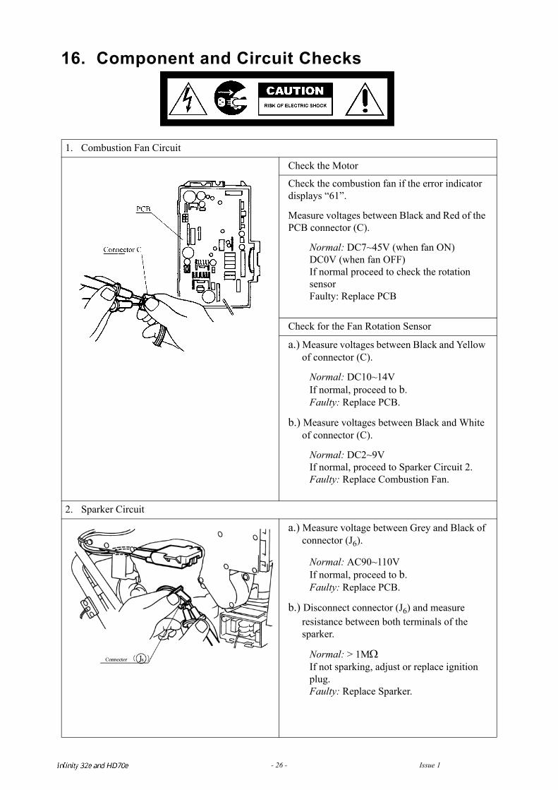
1. Combustion Fan Circuit
Check the Motor
Check the combustion fan if the error indicator displays “61”.
Measure voltages between Black and Red of the PCB connector (C).
Normal: DC7~45V (when fan ON)DC0V (when fan OFF)If normal proceed to check the rotation sensorFaulty: Replace PCB
Check for the Fan Rotation Sensor
a.) Measure voltages between Black and Yellow of connector (C).
Normal: DC10~14VIf normal, proceed to b.Faulty: Replace PCB.
b.) Measure voltages between Black and White of connector (C).
Normal: DC2~9VIf normal, proceed to Sparker Circuit 2.Faulty: Replace Combustion Fan.
2. Sparker Circuit
a.) Measure voltage between Grey and Black of connector (J6).
Normal: AC90~110VIf normal, proceed to b.Faulty: Replace PCB.
b.) Disconnect connector (J6) and measure resistance between both terminals of the sparker.
Normal: > 1MΩIf not sparking, adjust or replace ignition plug.Faulty: Replace Sparker.
Infinity REU-V3232W /HD250E REU-V3232WC - 26 - Issue 1 - 8/09/03 ©Rinnai
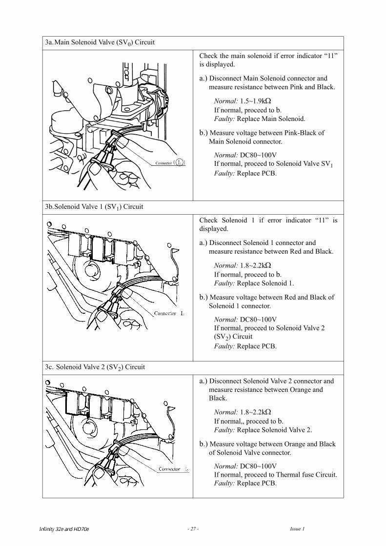
3a.Main Solenoid Valve (SV0) Circuit
Check the main solenoid if error indicator “11”is displayed.
a.) Disconnect Main Solenoid connector and measure resistance between Pink and Black.
Normal: 1.5~1.9kΩIf normal, proceed to b.Faulty: Replace Main Solenoid.
b.) Measure voltage between Pink-Black of Main Solenoid connector.
Normal: DC80~100VIf normal, proceed to Solenoid Valve SV1Faulty: Replace PCB.
3b.Solenoid Valve 1 (SV1) Circuit
Check Solenoid 1 if error indicator “11” isdisplayed.
a.) Disconnect Solenoid 1 connector and measure resistance between Red and Black.
Normal: 1.8~2.2kΩIf normal, proceed to b.Faulty: Replace Solenoid 1.
b.) Measure voltage between Red and Black of Solenoid 1 connector.
Normal: DC80~100VIf normal, proceed to Solenoid Valve 2 (SV2) CircuitFaulty: Replace PCB.
3c. Solenoid Valve 2 (SV2) Circuit
a.) Disconnect Solenoid Valve 2 connector and measure resistance between Orange and Black.
Normal: 1.8~2.2kΩIf normal,, proceed to b.Faulty: Replace Solenoid Valve 2.
b.) Measure voltage between Orange and Black of Solenoid Valve connector.
Normal: DC80~100VIf normal, proceed to Thermal fuse Circuit.Faulty: Replace PCB.
Infinity REU-V3232W /HD250E REU-V3232WC - 27 - Issue 1 - 8/09/03 ©Rinnai
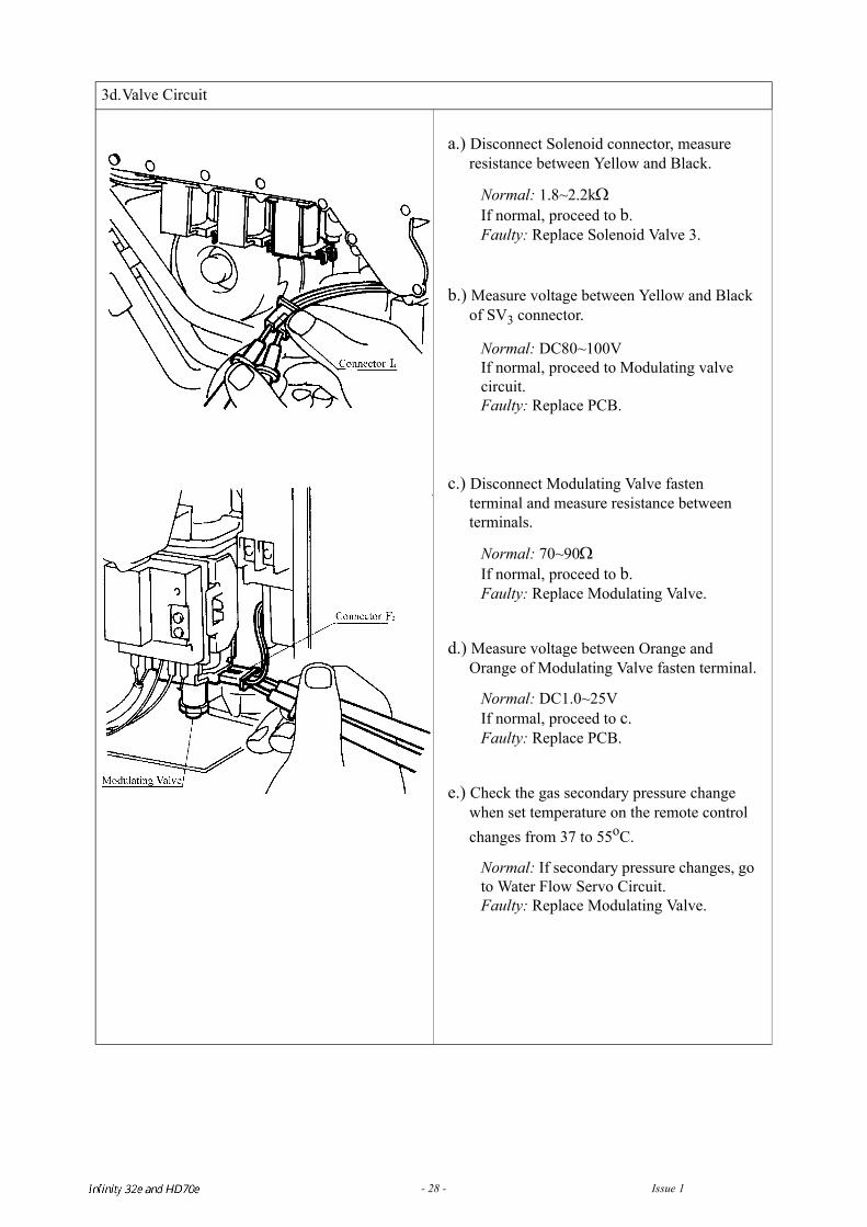
3d.Valve Circuit
a.) Disconnect Solenoid connector, measure resistance between Yellow and Black.
Normal: 1.8~2.2kΩIf normal, proceed to b.Faulty: Replace Solenoid Valve 3.
b.) Measure voltage between Yellow and Black of SV3 connector.
Normal: DC80~100VIf normal, proceed to Modulating valve circuit.Faulty: Replace PCB.
c.) Disconnect Modulating Valve fasten terminal and measure resistance between terminals.
Normal: 70~90ΩIf normal, proceed to b.Faulty: Replace Modulating Valve.
d.) Measure voltage between Orange and Orange of Modulating Valve fasten terminal.
Normal: DC1.0~25VIf normal, proceed to c.Faulty: Replace PCB.
e.) Check the gas secondary pressure change when set temperature on the remote control changes from 37 to 55oC.
Normal: If secondary pressure changes, go to Water Flow Servo Circuit.Faulty: Replace Modulating Valve.
Infinity REU-V3232W /HD250E REU-V3232WC - 28 - Issue 1 - 8/09/03 ©Rinnai
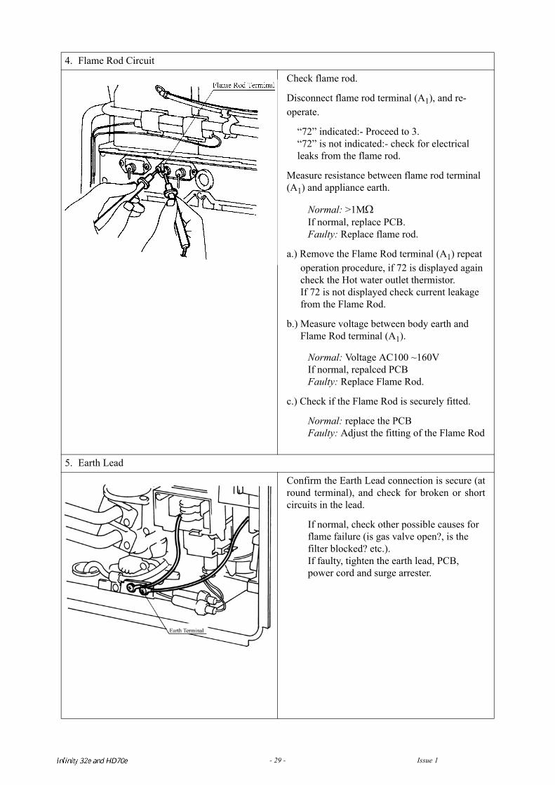
4. Flame Rod Circuit
Check flame rod.
Disconnect flame rod terminal (A1), and re-operate.
“72” indicated:- Proceed to 3.“72” is not indicated:- check for electrical leaks from the flame rod.
Measure resistance between flame rod terminal (A1) and appliance earth.
Normal: >1MΩIf normal, replace PCB.Faulty: Replace flame rod.
a.) Remove the Flame Rod terminal (A1) repeat operation procedure, if 72 is displayed again check the Hot water outlet thermistor.If 72 is not displayed check current leakage from the Flame Rod.
b.) Measure voltage between body earth and Flame Rod terminal (A1).
Normal: Voltage AC100 ~160VIf normal, repalced PCBFaulty: Replace Flame Rod.
c.) Check if the Flame Rod is securely fitted.
Normal: replace the PCBFaulty: Adjust the fitting of the Flame Rod
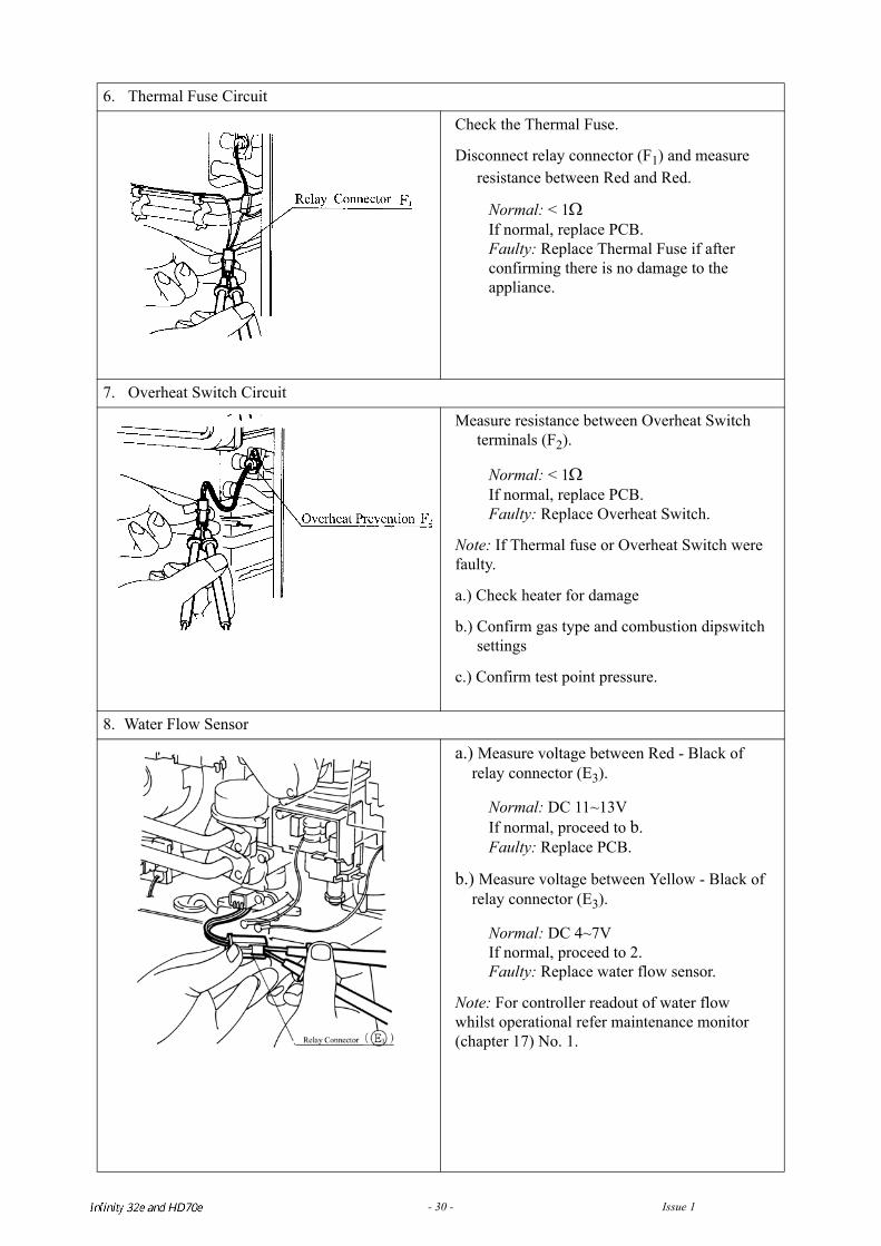
5. Earth Lead
Confirm the Earth Lead connection is secure (atround terminal), and check for broken or shortcircuits in the lead.
If normal, check other possible causes for flame failure (is gas valve open?, is the filter blocked? etc.).If faulty, tighten the earth lead, PCB, power cord and surge arrester.
Infinity REU-V3232W /HD250E REU-V3232WC - 29 - Issue 1 - 8/09/03 ©Rinnai
6. Thermal Fuse Circuit
Check the Thermal Fuse.
Disconnect relay connector (F1) and measure resistance between Red and Red.
Normal: < 1ΩIf normal, replace PCB.Faulty: Replace Thermal Fuse if after confirming there is no damage to the appliance.
7. Overheat Switch Circuit
Measure resistance between Overheat Switch terminals (F2).
Normal: < 1ΩIf normal, replace PCB.Faulty: Replace Overheat Switch.
Note: If Thermal fuse or Overheat Switch were faulty.
a.) Check heater for damage
b.) Confirm gas type and combustion dipswitch settings
c.) Confirm test point pressure.
8. Water Flow Sensor
a.) Measure voltage between Red - Black of relay connector (E3).
Normal: DC 11~13VIf normal, proceed to b.Faulty: Replace PCB.
b.) Measure voltage between Yellow - Black of relay connector (E3).
Normal: DC 4~7VIf normal, proceed to 2.Faulty: Replace water flow sensor.
Note: For controller readout of water flow whilst operational refer maintenance monitor (chapter 17) No. 1.
Infinity REU-V3232W /HD250E REU-V3232WC - 30 - Issue 1 - 8/09/03 ©Rinnai
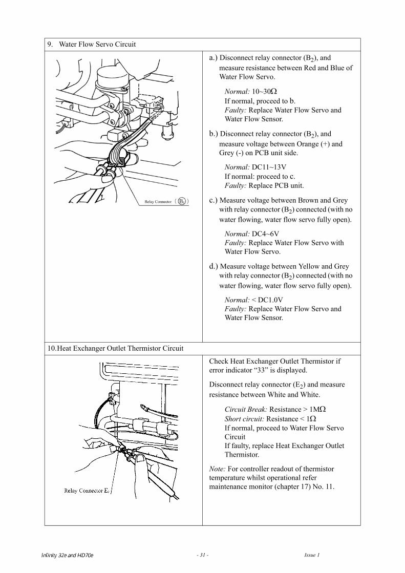
9. Water Flow Servo Circuit
a.) Disconnect relay connector (B2), and measure resistance between Red and Blue of Water Flow Servo.
Normal: 10~30ΩIf normal, proceed to b.Faulty: Replace Water Flow Servo and Water Flow Sensor.
b.) Disconnect relay connector (B2), and measure voltage between Orange (+) and Grey (-) on PCB unit side.
Normal: DC11~13VIf normal: proceed to c.Faulty: Replace PCB unit.
c.) Measure voltage between Brown and Grey with relay connector (B2) connected (with no water flowing, water flow servo fully open).
Normal: DC4~6VFaulty: Replace Water Flow Servo with Water Flow Servo.
d.) Measure voltage between Yellow and Grey with relay connector (B2) connected (with no water flowing, water flow servo fully open).
Normal: < DC1.0VFaulty: Replace Water Flow Servo and Water Flow Sensor.
10.Heat Exchanger Outlet Thermistor Circuit
Check Heat Exchanger Outlet Thermistor if error indicator “33” is displayed.
Disconnect relay connector (E2) and measure resistance between White and White.
Circuit Break: Resistance > 1MΩShort circuit: Resistance < 1ΩIf normal, proceed to Water Flow Servo CircuitIf faulty, replace Heat Exchanger Outlet Thermistor.
Note: For controller readout of thermistor temperature whilst operational refer maintenance monitor (chapter 17) No. 11.
Infinity REU-V3232W /HD250E REU-V3232WC - 31 - Issue 1 - 8/09/03 ©Rinnai
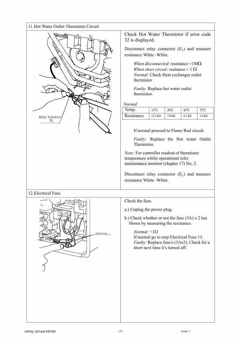
11.Hot Water Outlet Thermistor Circuit
Check Hot Water Thermistor if error code32 is displayed.
Disconnect relay connector (E1) and measureresistance White -White.
When disconnected: resistance >1MΩWhen short circuit: resitance > 1 ΩNormal: Check Heat exchanger outlet thermistor
Faulty: Replace hot water outlet thermistor.
If normal proceed to Flame Rod circuit.
Faulty: Replace the Hot water OutletThermistor.
Note: For controller readout of thermistor temperature whilst operational refer maintenance monitor (chapter 17) No. 2.
Disconnect relay connector (E1) and measureresistance White -White.
12.Electrical Fuse
Check the fuse.
a.) Unplug the power plug.
b.) Check whether or not the fuse (3A) x 2 has blown by measuring the resistance.
Normal: <1ΩIf normal go to step Electrical Fuse 13.Faulty: Replace fuse/s (3Ax2). Check for a short next time it’s turned off.
Normal Temp. 15oC 30oC 45oC 75oCResistance 12.3 kΩ 7.0 kΩ 4.1 kΩ 1.6 kΩ
Infinity REU-V3232W /HD250E REU-V3232WC - 32 - Issue 1 - 8/09/03 ©Rinnai
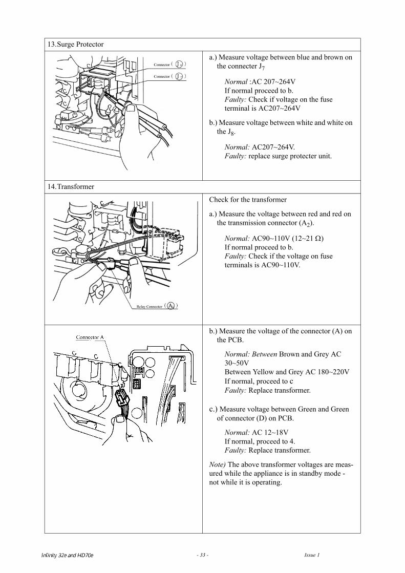
13.Surge Protector
a.) Measure voltage between blue and brown on the connecter J7
Normal :AC 207~264VIf normal proceed to b.Faulty: Check if voltage on the fuse terminal is AC207~264V
b.) Measure voltage between white and white on the J8.
Normal: AC207~264V.Faulty: replace surge protecter unit.
14.Transformer
Check for the transformer
a.) Measure the voltage between red and red on the transmission connector (A2).
Normal: AC90~110V (12~21 Ω)If normal proceed to b.Faulty: Check if the voltage on fuse terminals is AC90~110V.
b.) Measure the voltage of the connector (A) on the PCB.
Normal: Between Brown and Grey AC 30~50VBetween Yellow and Grey AC 180~220VIf normal, proceed to cFaulty: Replace transformer.
c.) Measure voltage between Green and Green of connector (D) on PCB.
Normal: AC 12~18VIf normal, proceed to 4.Faulty: Replace transformer.
Note) The above transformer voltages are meas-ured while the appliance is in standby mode - not while it is operating.
Infinity REU-V3232W /HD250E REU-V3232WC - 33 - Issue 1 - 8/09/03 ©Rinnai
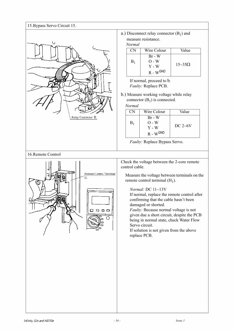
15.Bypass Servo Circuit 15.
a.) Disconnect relay connector (B1) and measure resistance.
If normal, proceed to b.Faulty: Replace PCB.
b.) Measure working voltage while relay connector (B1) is connected.
Faulty: Replace Bypass Servo.
16.Remote Control
Check the voltage between the 2-core remote control cable.
Measure the voltage between terminals on the remote control terminal (H1).
Normal: DC 11~13VIf normal, replace the remote control after confirming that the cable hasn’t been damaged or shorted.Faulty: Because normal voltage is not given due a short circuit, despite the PCB being in normal state, check Water Flow Servo circuit.If solution is not given from the above replace PCB.
Normal CN Wire Colour Value
B1
Br - WO - WY - WR - WGND
15~35Ω
Normal CN Wire Colour Value
B1
Br - WO - WY - WR - WGND
DC 2~6V
Infinity REU-V3232W /HD250E REU-V3232WC - 34 - Issue 1 - 8/09/03 ©Rinnai
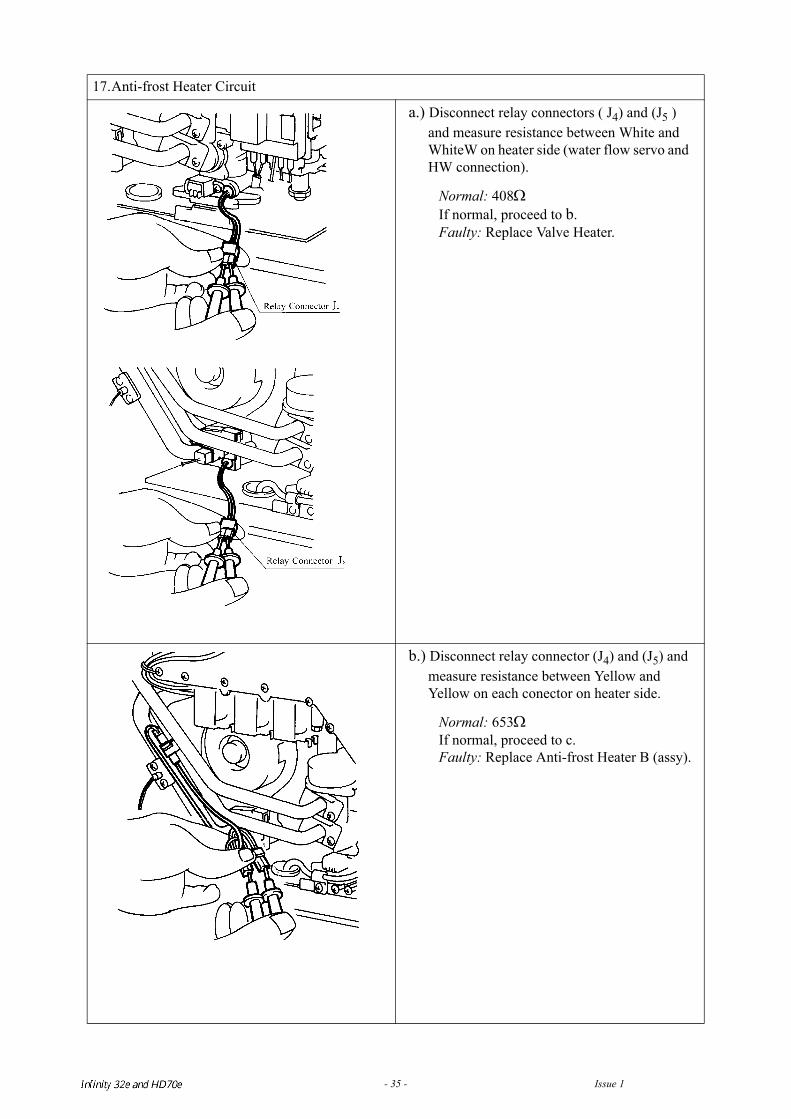
17.Anti-frost Heater Circuit
a.) Disconnect relay connectors ( J4) and (J5 ) and measure resistance between White and WhiteW on heater side (water flow servo and HW connection).
Normal: 408ΩIf normal, proceed to b.Faulty: Replace Valve Heater.
b.) Disconnect relay connector (J4) and (J5) and measure resistance between Yellow and Yellow on each conector on heater side.
Normal: 653ΩIf normal, proceed to c.Faulty: Replace Anti-frost Heater B (assy).
Infinity REU-V3232W /HD250E REU-V3232WC - 35 - Issue 1 - 8/09/03 ©Rinnai
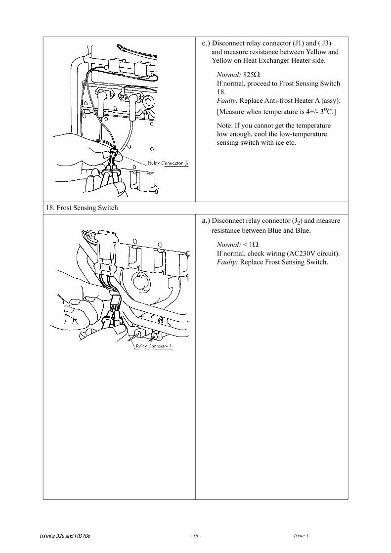
c.) Disconnect relay connector (J1) and ( J3) and measure resistance between Yellow and Yellow on Heat Exchanger Heater side.
Normal: 825ΩIf normal, proceed to Frost Sensing Switch 18.Faulty: Replace Anti-frost Heater A (assy). [Measure when temperature is 4+/- 3oC.]
Note: If you cannot get the temperature low enough, cool the low-temperature sensing switch with ice etc.
18. Frost Sensing Switch
a.) Disconnect relay connector (J2) and measure resistance between Blue and Blue.
Normal: < 1ΩIf normal, check wiring (AC230V circuit).Faulty: Replace Frost Sensing Switch.
Infinity REU-V3232W /HD250E REU-V3232WC - 36 - Issue 1 - 8/09/03 ©Rinnai
17. Maintenance Monitor / Error History
This feature is available where the appliances are connected with a deluxe controller (MC70-2A orBC70-2A). This will enable service personnel to locate the maintenance history and faultycomponents, with the appliance in operation.
NB. When the maintenance information, error history is shown, use only one controller. If two or moreremote controls are used at the same time, it may not operate correctly.
To display Maintenance Information
Note: Infinity 32e and HD70e use Maintenance Numbers 1-12.
*Note 1 Fan Frequency rpm Conversion(rpm) = (Hz) x15
*Note 2 Remote Control Connections
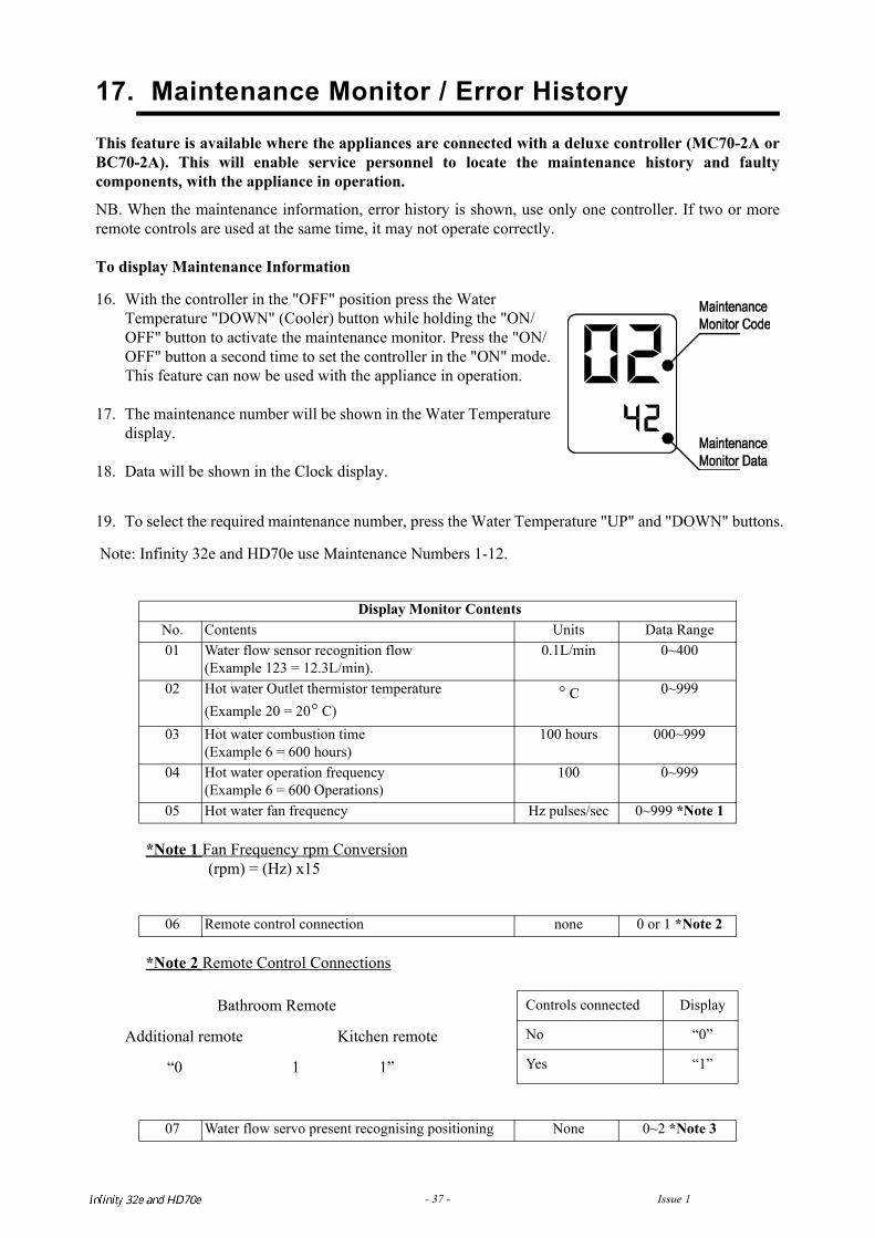
16. With the controller in the "OFF" position press the Water Temperature "DOWN" (Cooler) button while holding the "ON/OFF" button to activate the maintenance monitor. Press the "ON/OFF" button a second time to set the controller in the "ON" mode. This feature can now be used with the appliance in operation.
17. The maintenance number will be shown in the Water Temperature display.
18. Data will be shown in the Clock display.
19. To select the required maintenance number, press the Water Temperature "UP" and "DOWN" buttons.
Display Monitor Contents No. Contents Units Data Range01 Water flow sensor recognition flow
(Example 123 = 12.3L/min).0.1L/min 0~400
02 Hot water Outlet thermistor temperature(Example 20 = 20 C)
C 0~999
03 Hot water combustion time(Example 6 = 600 hours)
100 hours 000~999
04 Hot water operation frequency(Example 6 = 600 Operations)
100 0~999
05 Hot water fan frequency Hz pulses/sec 0~999 *Note 1
06 Remote control connection none 0 or 1 *Note 2
Bathroom Remote
Additional remote Kitchen remote
“0 1 1”
Controls connected Display
No “0”
Yes “1”
07 Water flow servo present recognising positioning None 0~2 *Note 3
°°
Infinity REU-V3232W /HD250E REU-V3232WC - 37 - Issue 1 - 8/09/03 ©Rinnai
*Note 3 Water Flow Servo Positioning
To return to normal operation• Press the ON/OFF button again while holding down the Water Temperature "DOWN" (Cooler)
button.
To return to normal operation.
• Press the ON/OFF button again while holding the Water Temperature “UP” (Hotter) button.
• This feature will automatically shut down after 3 minutes.
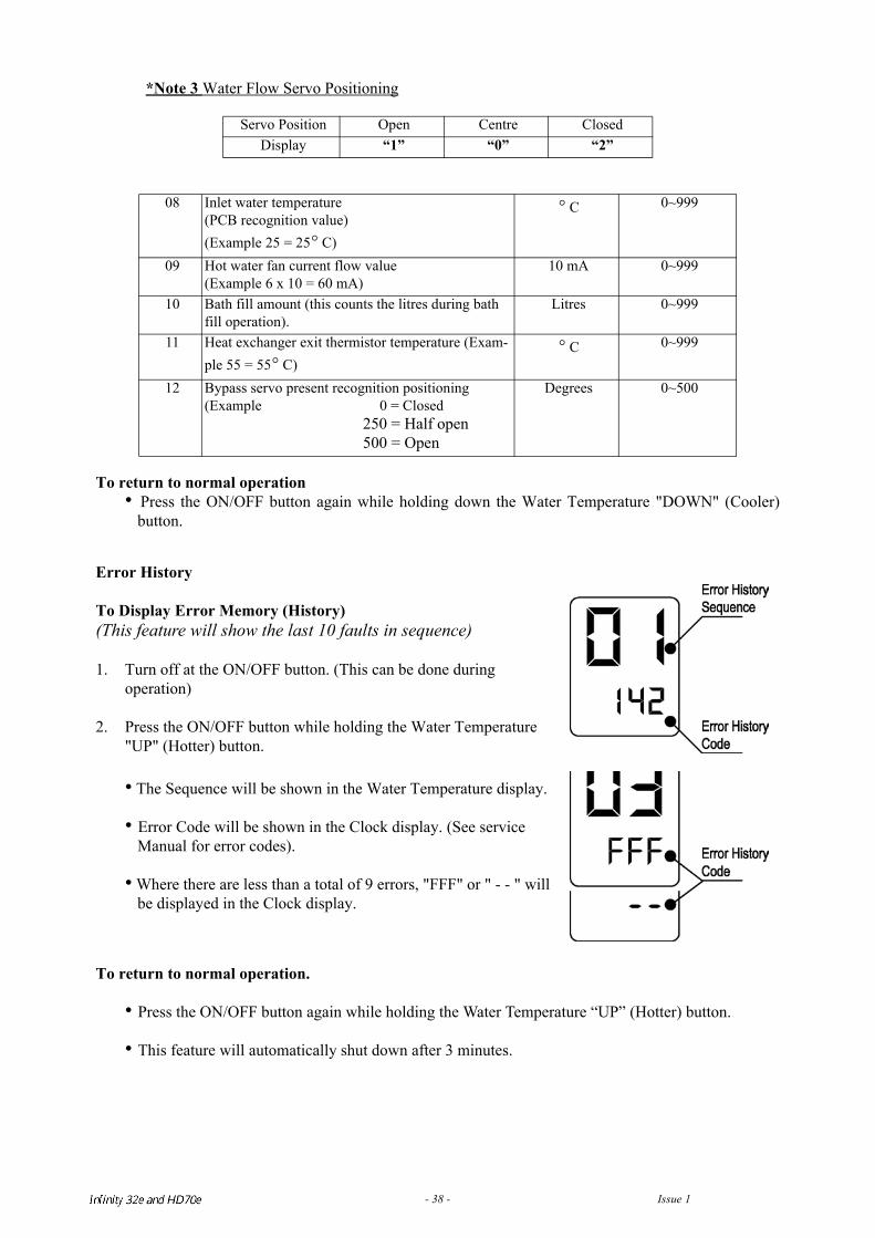
Servo Position Open Centre ClosedDisplay “1” “0” “2”
08 Inlet water temperature(PCB recognition value)(Example 25 = 25 C)
C 0~999
09 Hot water fan current flow value(Example 6 x 10 = 60 mA)
10 mA 0~999
10 Bath fill amount (this counts the litres during bath fill operation).
Litres 0~999
11 Heat exchanger exit thermistor temperature (Exam-ple 55 = 55 C)
C 0~999
12 Bypass servo present recognition positioning(Example 0 = Closed
250 = Half open 500 = Open
Degrees 0~500
Error History
To Display Error Memory (History)(This feature will show the last 10 faults in sequence) 1. Turn off at the ON/OFF button. (This can be done during
operation)
2. Press the ON/OFF button while holding the Water Temperature "UP" (Hotter) button.
• The Sequence will be shown in the Water Temperature display.
• Error Code will be shown in the Clock display. (See service Manual for error codes).
• Where there are less than a total of 9 errors, "FFF" or " - - " will be displayed in the Clock display.
°
°
°°
Infinity REU-V3232W /HD250E REU-V3232WC - 38 - Issue 1 - 8/09/03 ©Rinnai
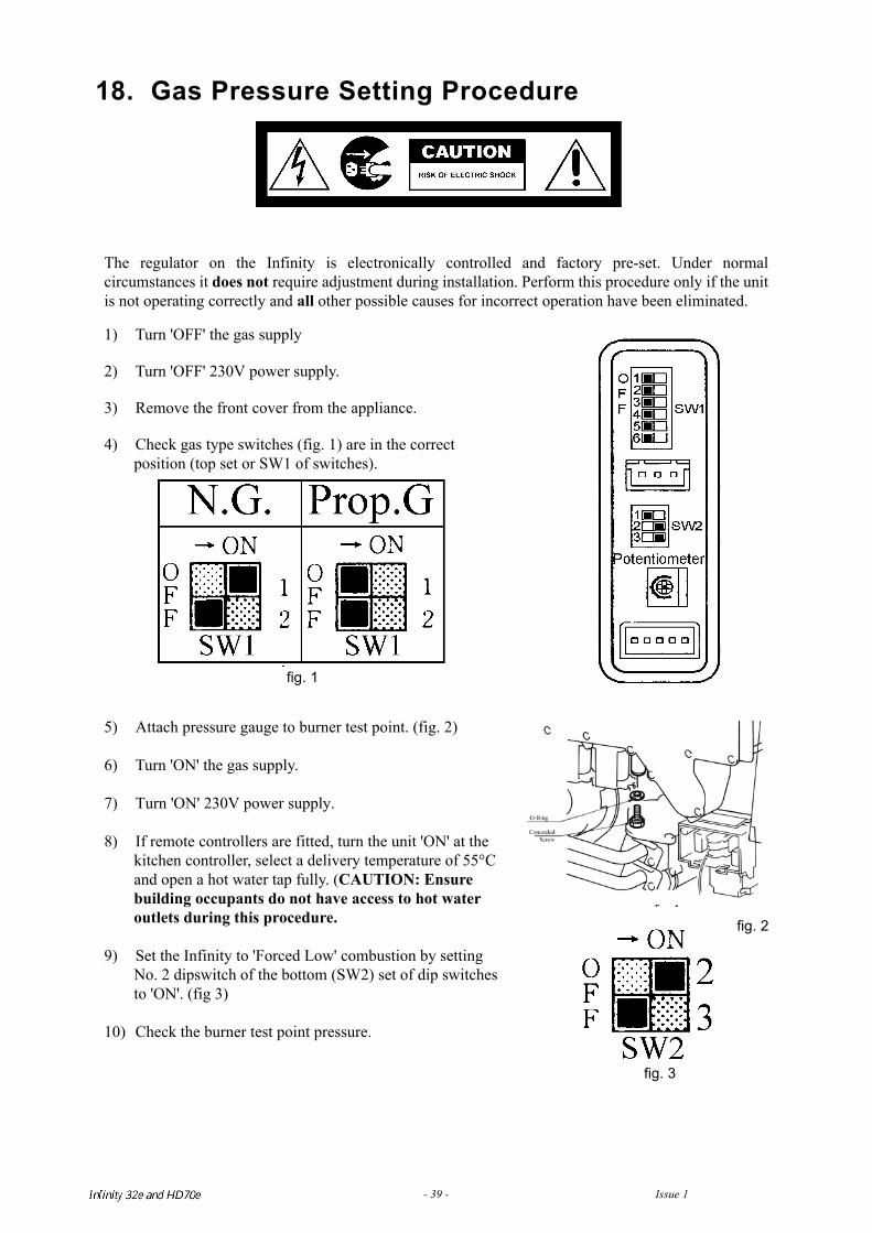
18. Gas Pressure Setting Procedure
The regulator on the Infinity is electronically controlled and factory pre-set. Under normalcircumstances it does not require adjustment during installation. Perform this procedure only if the unitis not operating correctly and all other possible causes for incorrect operation have been eliminated.
1) Turn 'OFF' the gas supply
2) Turn 'OFF' 230V power supply.
3) Remove the front cover from the appliance.
4) Check gas type switches (fig. 1) are in the correct position (top set or SW1 of switches).
5) Attach pressure gauge to burner test point. (fig. 2)
6) Turn 'ON' the gas supply.
7) Turn 'ON' 230V power supply.
8) If remote controllers are fitted, turn the unit 'ON' at the kitchen controller, select a delivery temperature of 55°C and open a hot water tap fully. (CAUTION: Ensure building occupants do not have access to hot water outlets during this procedure.
9) Set the Infinity to 'Forced Low' combustion by setting No. 2 dipswitch of the bottom (SW2) set of dip switches to 'ON'. (fig 3)
10) Check the burner test point pressure.
fig. 1
fi 1
fig. 3
fig. 2
Infinity REU-V3232W /HD250E REU-V3232WC - 39 - Issue 1 - 8/09/03 ©Rinnai
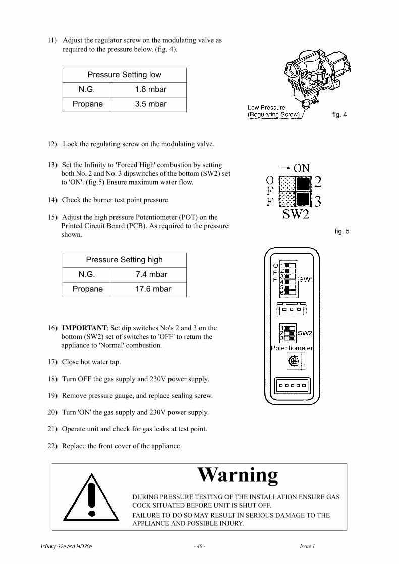
11) Adjust the regulator screw on the modulating valve as required to the pressure below. (fig. 4).
12) Lock the regulating screw on the modulating valve.
Pressure Setting low
N.G. 1.8 mbar
Propane 3.5 mbar
LPG (NZ) 0.35 kPa
13) Set the Infinity to 'Forced High' combustion by setting both No. 2 and No. 3 dipswitches of the bottom (SW2) set to 'ON'. (fig.5) Ensure maximum water flow.
14) Check the burner test point pressure.
15) Adjust the high pressure Potentiometer (POT) on the Printed Circuit Board (PCB). As required to the pressure shown.
Pressure Setting high
N.G. 7.4 mbar
Propane 17.6 mbar
LPG (NZ) 1.53 kPa
16) IMPORTANT: Set dip switches No's 2 and 3 on the bottom (SW2) set of switches to 'OFF' to return the appliance to 'Normal' combustion.
17) Close hot water tap.
18) Turn OFF the gas supply and 230V power supply.
19) Remove pressure gauge, and replace sealing screw.
20) Turn 'ON' the gas supply and 230V power supply.
21) Operate unit and check for gas leaks at test point.
22) Replace the front cover of the appliance.
WarningDURING PRESSURE TESTING OF THE INSTALLATION ENSURE GAS COCK SITUATED BEFORE UNIT IS SHUT OFF.FAILURE TO DO SO MAY RESULT IN SERIOUS DAMAGE TO THE APPLIANCE AND POSSIBLE INJURY.
fig. 4
fig. 5
Infinity REU-V3232W /HD250E REU-V3232WC - 40 - Issue 1 - 8/09/03 ©Rinnai
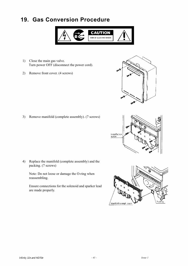
19. Gas Conversion Procedure
1) Close the main gas valve.Turn power OFF (disconnect the power cord).
2) Remove front cover. (4 screws)
3) Remove manifold (complete assembly). (7 screws)
4) Replace the manifold (complete assembly) and the packing. (7 screws)
Note: Do not loose or damage the O-ring when reassembling.
Ensure connections for the solenoid and sparker lead are made properly.
Infinity REU-V3232W /HD250E REU-V3232WC - 41 - Issue 1 - 8/09/03 ©Rinnai
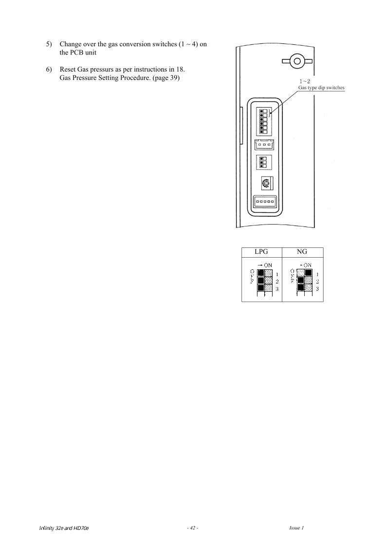
5) Change over the gas conversion switches (1 ~ 4) on the PCB unit
6) Reset Gas pressurs as per instructions in 18. Gas Pressure Setting Procedure. (page 39)
LPG NG
Infinity REU-V3232W /HD250E REU-V3232WC - 42 - Issue 1 - 8/09/03 ©Rinnai
20. Dismantling for Service
230 volt potential exposure. Isolate the appliance and confirm with a multimeter.
Item Page1. Removal of the Front Panel . . . . . . . . . . . . . . . . . . . . . . . . . . . . . . . . . . . . . . . . . . . . . 44
2. Removal of the PCB Unit . . . . . . . . . . . . . . . . . . . . . . . . . . . . . . . . . . . . . . . . . . . . . . . 44
3. Removal of the Water Flow Sensor, Servo and Bypass Servo . . . . . . . . . . . . . . . . . 44
4. Removal of the Sparkers . . . . . . . . . . . . . . . . . . . . . . . . . . . . . . . . . . . . . . . . . . . . . . . 45
5. Removal of the Combustion Fan . . . . . . . . . . . . . . . . . . . . . . . . . . . . . . . . . . . . . . . . . 45
6. Removal of the Hot Water Outlet & Heat Exchanger Outlet Thermistors. . . . . . . 45
7. Removal of the Transformers . . . . . . . . . . . . . . . . . . . . . . . . . . . . . . . . . . . . . . . . . . . 45
8. Removal of the Gas Inlet, Solenoids and Flame Rod . . . . . . . . . . . . . . . . . . . . . . . . 46
9. Removal of the Gas Control. . . . . . . . . . . . . . . . . . . . . . . . . . . . . . . . . . . . . . . . . . . . . 46
10. Removal of the Heat Exchanger . . . . . . . . . . . . . . . . . . . . . . . . . . . . . . . . . . . . . . . . . 47
11. Removal of the Thermal Fuse and OHS. . . . . . . . . . . . . . . . . . . . . . . . . . . . . . . . . . . 47
Unless otherwise stated, re-assembly is the reverse of dismantling.
Infinity REU-V3232W /HD250E REU-V3232WC - 43 - Issue 1 - 8/09/03 ©Rinnai
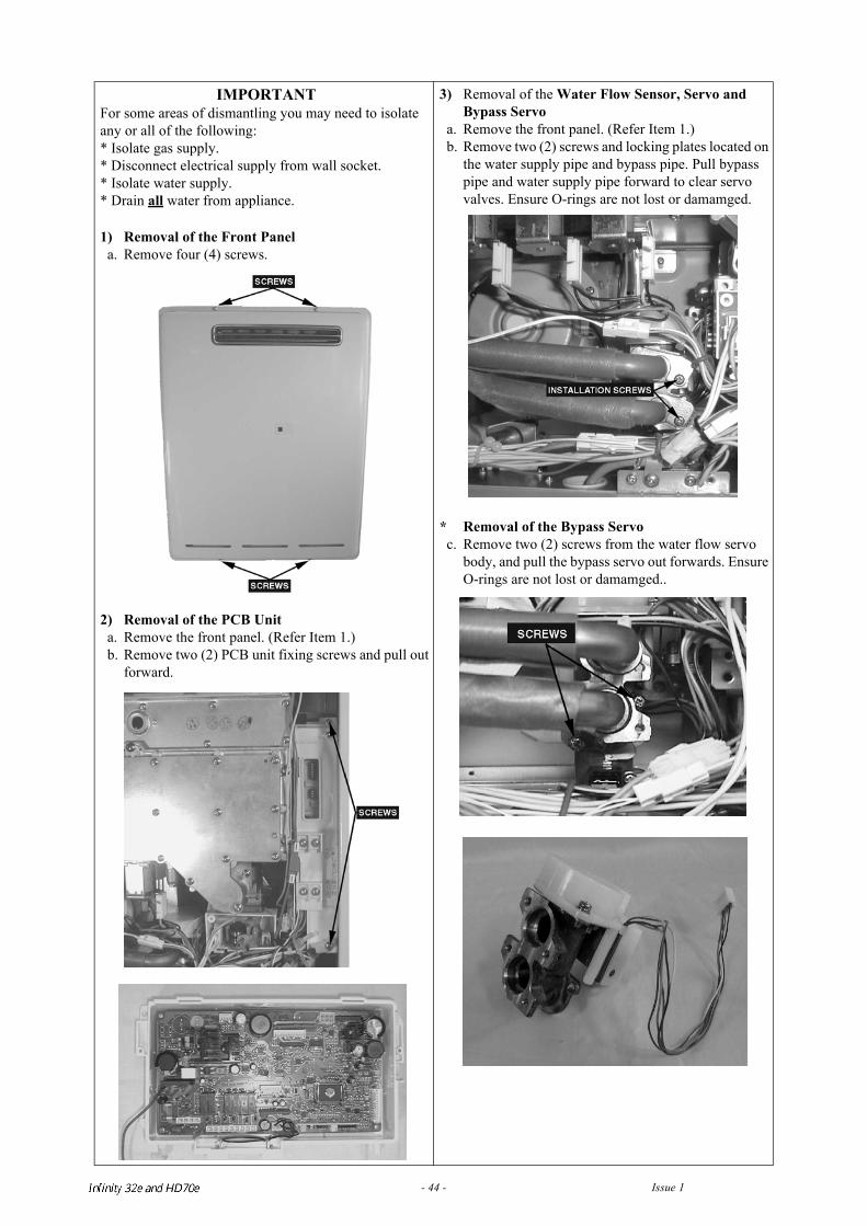
IMPORTANTFor some areas of dismantling you may need to isolate any or all of the following:* Isolate gas supply.* Disconnect electrical supply from wall socket.* Isolate water supply.* Drain all water from appliance.
1) Removal of the Front Panela. Remove four (4) screws.
2) Removal of the PCB Unita. Remove the front panel. (Refer Item 1.)b. Remove two (2) PCB unit fixing screws and pull out
forward.
3) Removal of the Water Flow Sensor, Servo and Bypass Servo
a. Remove the front panel. (Refer Item 1.)b. Remove two (2) screws and locking plates located on
the water supply pipe and bypass pipe. Pull bypass pipe and water supply pipe forward to clear servo valves. Ensure O-rings are not lost or damamged.
* Removal of the Bypass Servoc. Remove two (2) screws from the water flow servo
body, and pull the bypass servo out forwards. Ensure O-rings are not lost or damamged..
Infinity REU-V3232W /HD250E REU-V3232WC - 44 - Issue 1 - 8/09/03 ©Rinnai
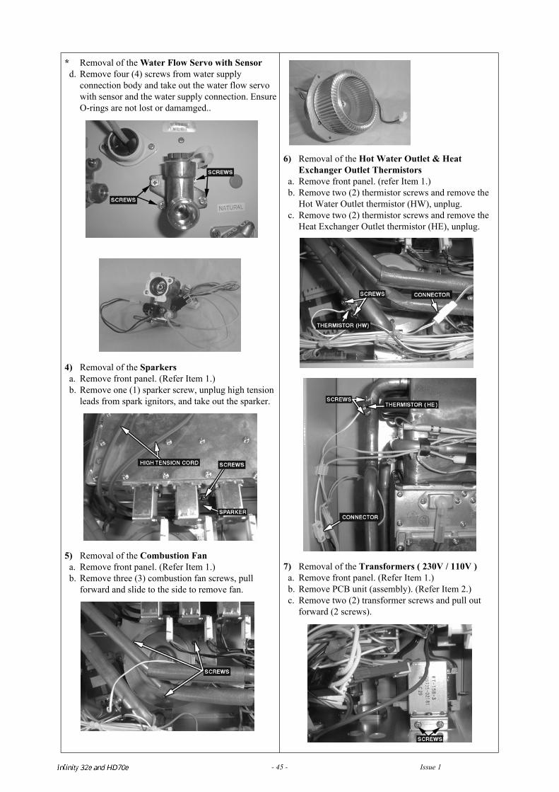
* Removal of the Water Flow Servo with Sensord. Remove four (4) screws from water supply
connection body and take out the water flow servo with sensor and the water supply connection. Ensure O-rings are not lost or damamged..
4) Removal of the Sparkersa. Remove front panel. (Refer Item 1.)b. Remove one (1) sparker screw, unplug high tension
leads from spark ignitors, and take out the sparker.
5) Removal of the Combustion Fana. Remove front panel. (Refer Item 1.)b. Remove three (3) combustion fan screws, pull
forward and slide to the side to remove fan.
6) Removal of the Hot Water Outlet & Heat Exchanger Outlet Thermistors
a. Remove front panel. (refer Item 1.)b. Remove two (2) thermistor screws and remove the
Hot Water Outlet thermistor (HW), unplug.c. Remove two (2) thermistor screws and remove the
Heat Exchanger Outlet thermistor (HE), unplug.
7) Removal of the Transformers ( 230V / 110V )a. Remove front panel. (Refer Item 1.)b. Remove PCB unit (assembly). (Refer Item 2.)c. Remove two (2) transformer screws and pull out
forward (2 screws).
Infinity REU-V3232W /HD250E REU-V3232WC - 45 - Issue 1 - 8/09/03 ©Rinnai
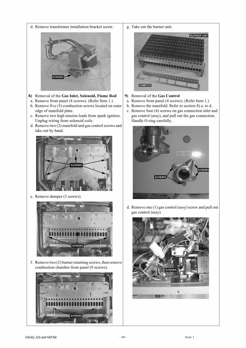
d. Remove transformer installation bracket screw.
8) Removal of the Gas Inlet, Solenoid, Flame Roda. Remove front panel (4 screws). (Refer Item 1.)b. Remove five (5) combustion screws located on outer
edge of manifold plate. c. Remove two high tension leads from spark ignitors.
Unplug wiring from solenoid coils.d. Remove two (2) manifold and gas control screws and
take out by hand.
e. Remove damper (3 screws).
f. Remove two (2) burner retaining screws, then remove combustion chamber front panel (9 screws).
g. Take out the burner unit.
9) Removal of the Gas Controla. Remove front panel (4 screws). (Refer Item 1.)b. Remove the manifold. Refer to section 8) a. to d.c. Remove four (4) screws on gas connection inlet and
gas control (assy), and pull out the gas connection. Handle O-ring carefully.
d. Remove one (1) gas control (assy) screw and pull out gas control (assy).
Infinity REU-V3232W /HD250E REU-V3232WC - 46 - Issue 1 - 8/09/03 ©Rinnai
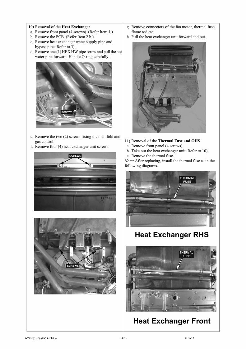
10) Removal of the Heat Exchangera. Remove front panel (4 screws). (Refer Item 1.)b. Remove the PCB. (Refer Item 2.b.) c. Remove heat exchanger water supply pipe and
bypass pipe. Refer to 3).d. Remove one (1) HEX HW pipe screw and pull the hot
water pipe forward. Handle O-ring carefully..
e. Remove the two (2) screws fixing the manifold and gas control.
f. Remove four (4) heat exchanger unit screws.
g. Remove connectors of the fan motor, thermal fuse, flame rod etc.
h. Pull the heat exchanger unit forward and out.
11) Removal of the Thermal Fuse and OHSa. Remove front panel (4 screws).b. Take out the heat exchanger unit. Refer to 10).c. Remove the thermal fuse.
Note: After replacing, install the thermal fuse as in the following diagrams.
Heat Exchanger RHS
Heat Exchanger Front
Infinity REU-V3232W /HD250E REU-V3232WC - 47 - Issue 1 - 8/09/03 ©Rinnai
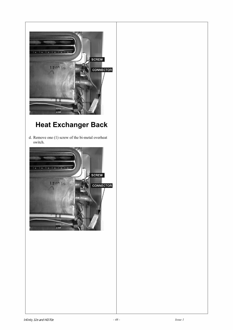
Heat Exchanger Backd. Remove one (1) screw of the bi-metal overheat
switch.
Infinity REU-V3232W /HD250E REU-V3232WC - 48 - Issue 1 - 8/09/03 ©Rinnai
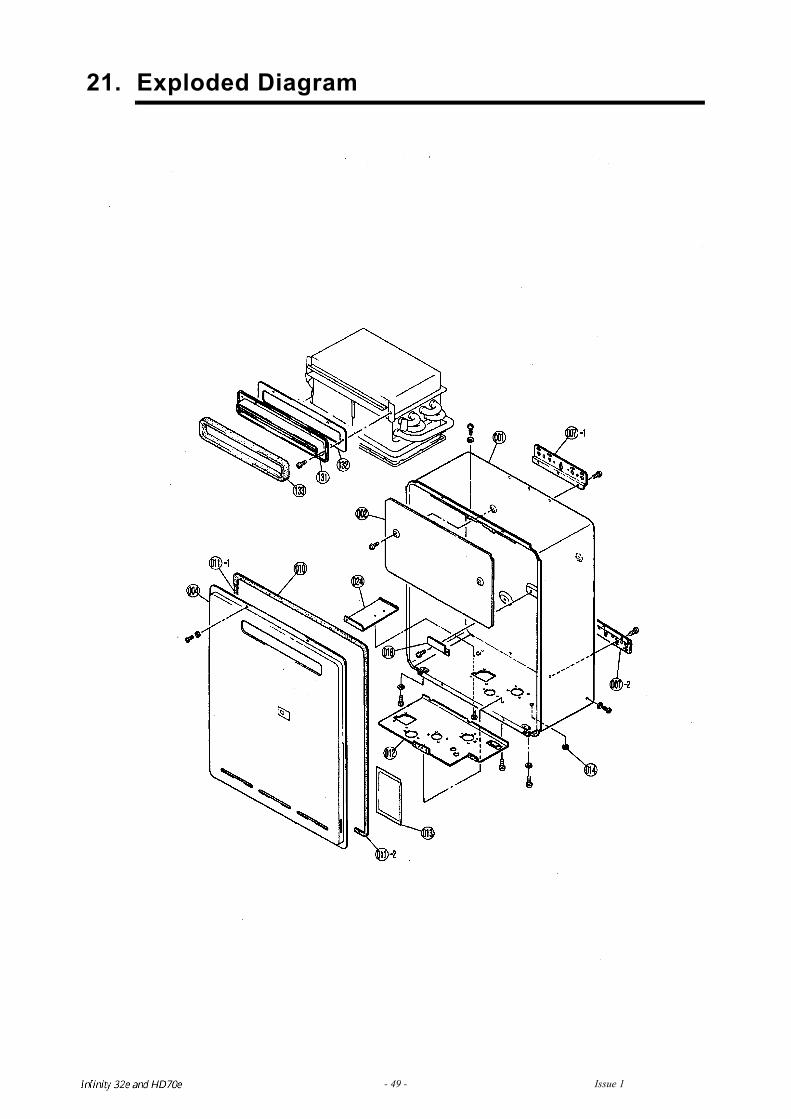
21. Exploded Diagram
Infinity REU-V3232W /HD250E REU-V3232WC - 49 - Issue 1 - 8/09/03 ©Rinnai
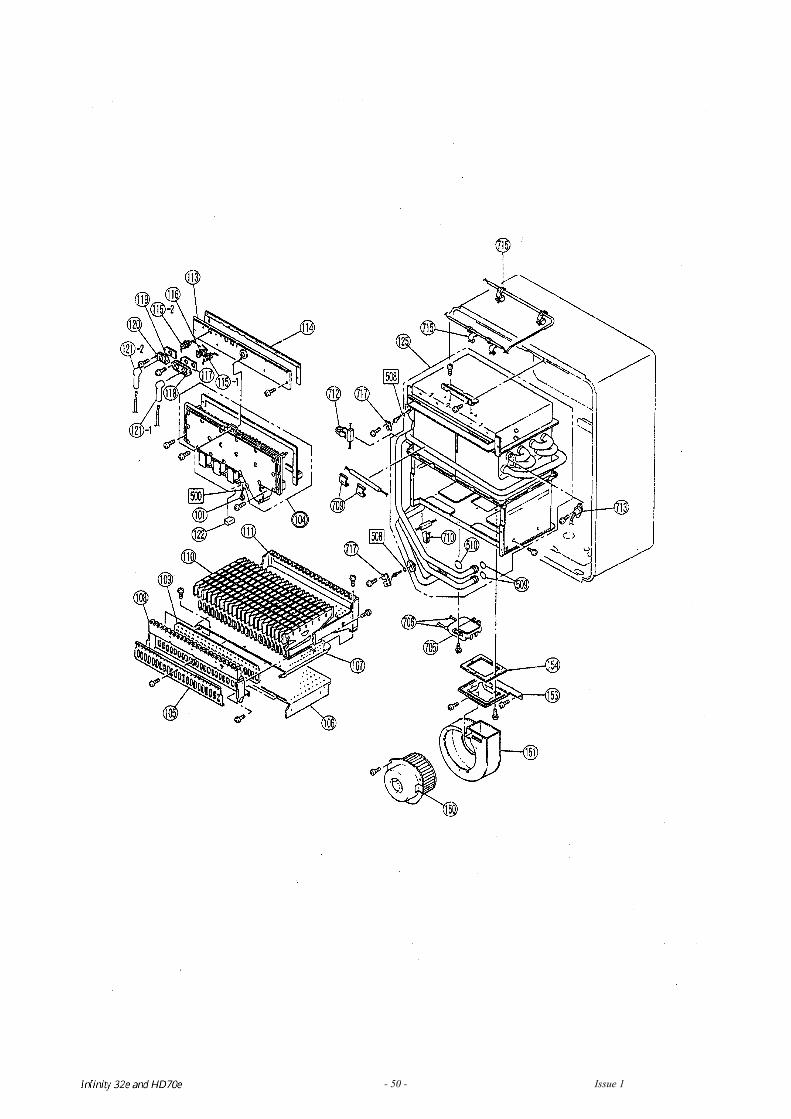
Infinity REU-V3232W /HD250E REU-V3232WC - 50 - Issue 1 - 8/09/03 ©Rinnai
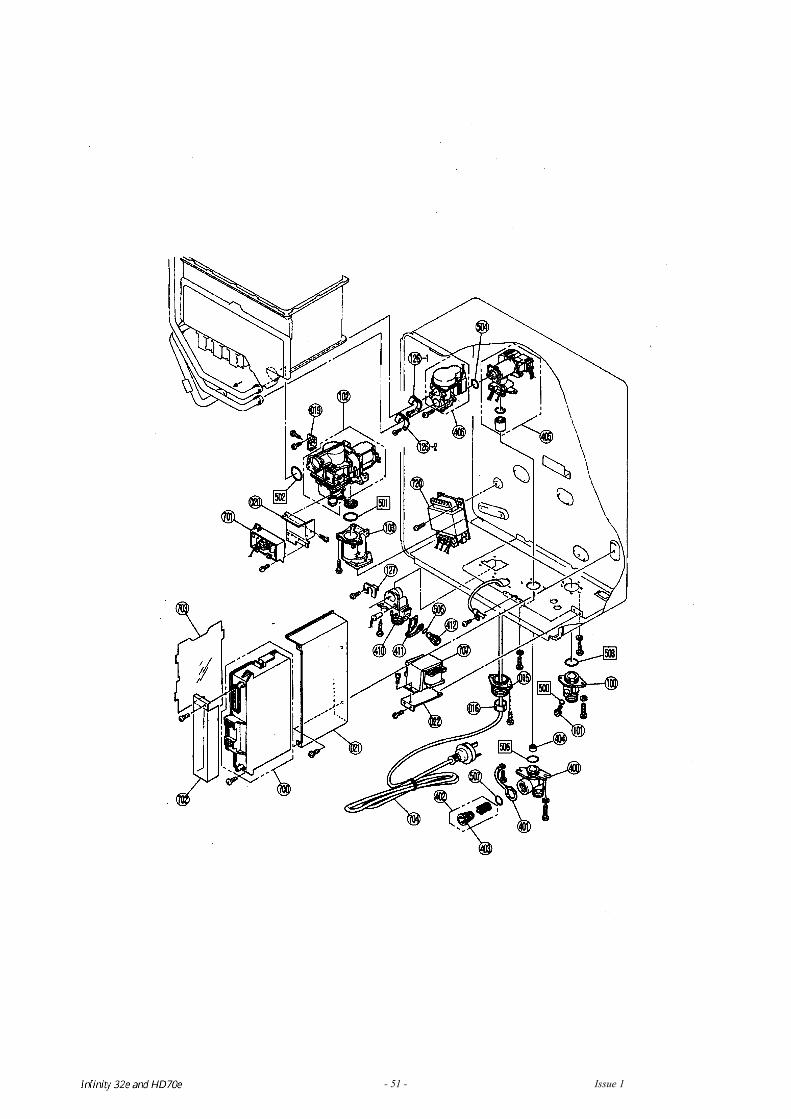
Infinity REU-V3232W /HD250E REU-V3232WC - 51 - Issue 1 - 8/09/03 ©Rinnai
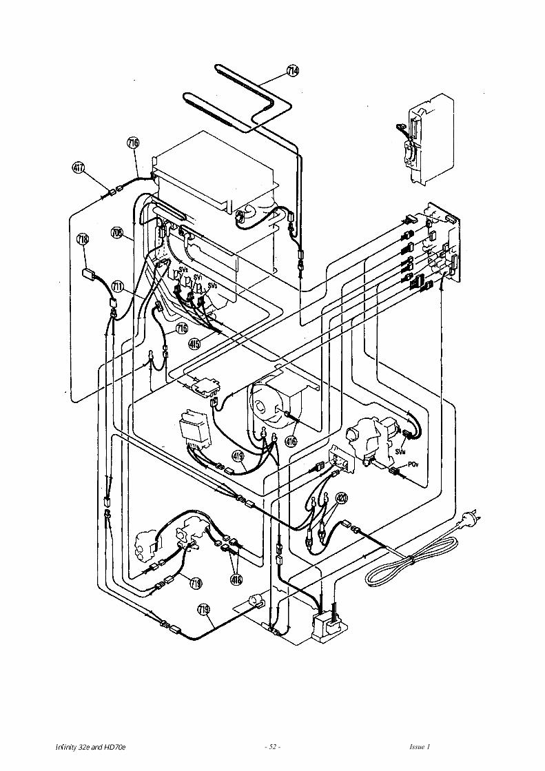
Infinity REU-V3232W /HD250E REU-V3232WC - 52 - Issue 1 - 8/09/03 ©Rinnai
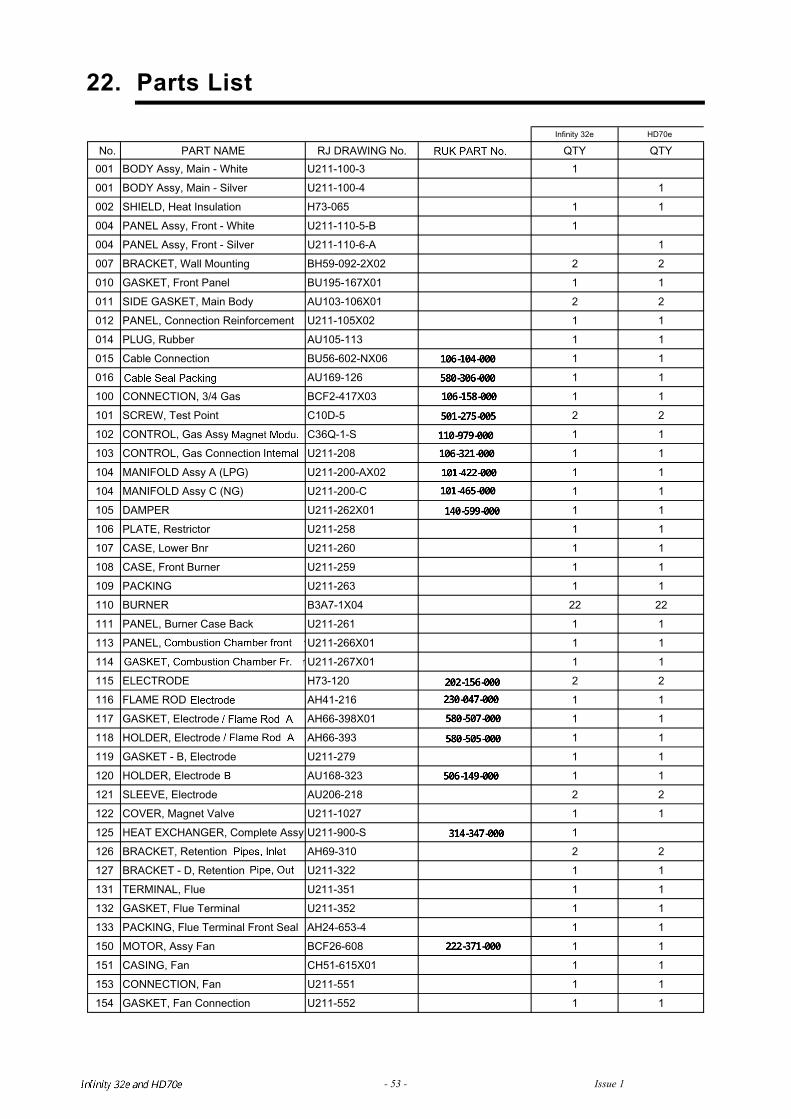
22. Parts List
Infinity 32e HD70e
Infinity REU-V3232W /HD250E REU-V3232WC - 53 - Issue 1 - 8/09/03 ©Rinnai
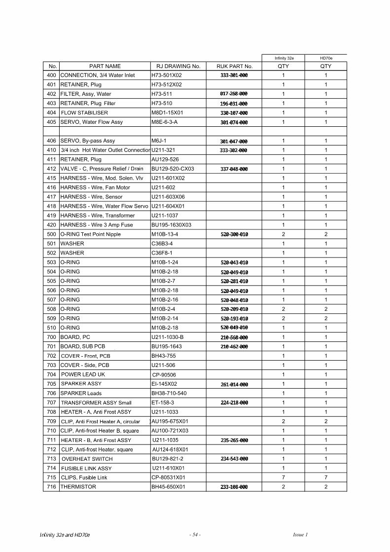
Infinity 32e HD70e
Infinity REU-V3232W /HD250E REU-V3232WC - 54 - Issue 1 - 8/09/03 ©Rinnai
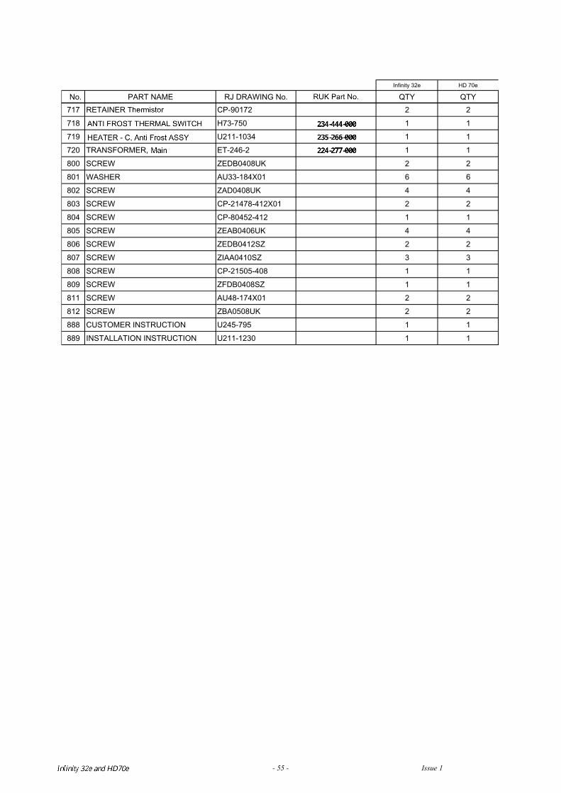
Infinity 32e HD 70e
Infinity REU-V3232W /HD250E REU-V3232WC - 55 - Issue 1 - 8/09/03 ©Rinnai

Infinity REU-V3232W /HD250E REU-V3232WC - 56 - Issue 1 - 8/09/03 ©Rinnai
Notes