Embed Size (px)
Citation preview
Managed by UT-Battellefor the Department of Energy
Jeff Holmes
Sarah Cousineau, Slava Danilov,Tom Peleia, Mike Plum, AndreiShishlo, and Zhengzheng Liu
Accelerator Advisory Committee
February 3, 2010
Ring Beam Dynamics Progress
2 Managed by UT-Battellefor the Department of Energy
Outline
A detailed understanding of ring beam dynamics requiresexperimental study, theoretical insight, and painstaking computationalbenchmarking.
Ring Optics Analysis
– Linear optics and beta beating
– Resonance map
Benchmarks of accumulation and painting
Losses in the injection chicane
Instabilities
– Benchmark of extraction kicker instability
– Electron cloud observations
ORBIT Code status
– Support and develop ORBIT for many users
– Migration to Python-based ORBIT
Presentation_name
3 Managed by UT-Battellefor the Department of Energy Ring Beam Dynamics Progress
January 22-24, 2008
Ring Optics (Zhengzheng Liu and Sarah Cousineau)
One year ago:
– The ORM method had been used to determinecorrection factors for the six quadrupole magnetfamilies, and these were included in the onlinemodel and the tune setpoint generator.
– With the correction factors, the predicted tuneswere within 0.01 over νx = 6.23-6.41 and νy = 6.20-6.37.
– The corrected dispersion and the averaged βfunction had been measured for the “production”set point.
– With the corrected quadrupole strengths, themodel predicted small βx beating, but there wasstill significant beating in βy.

4 Managed by UT-Battellefor the Department of Energy
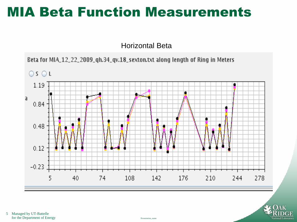
Present Situation and Next Steps
Today
– We routinely use the ORM-derived correctionfactors to determine the lattice setpoints.
– However, beta function measurements usingModel Independent Analysis (MIA) showsignificant amounts of beta beating in bothhorizontal and vertical planes. The beta beating isnot fourfold symmetric.
– Computational studies are underway to determinethe extent of possible correction
using the six symmetric knobs, and
using the quadrupole correctors.
Presentation_name
5 Managed by UT-Battellefor the Department of Energy
MIA Beta Function Measurements
Presentation_name
Horizontal Beta
6 Managed by UT-Battellefor the Department of Energy
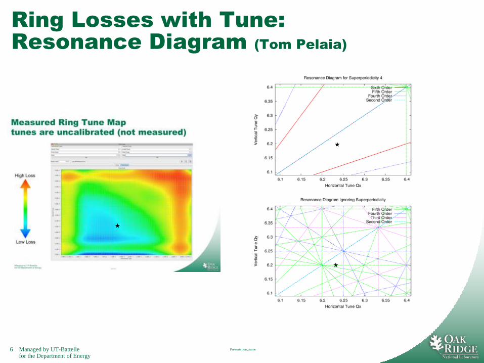
Ring Losses with Tune:
Resonance Diagram (Tom Pelaia)
Presentation_name
★
★
★
7 Managed by UT-Battellefor the Department of Energy
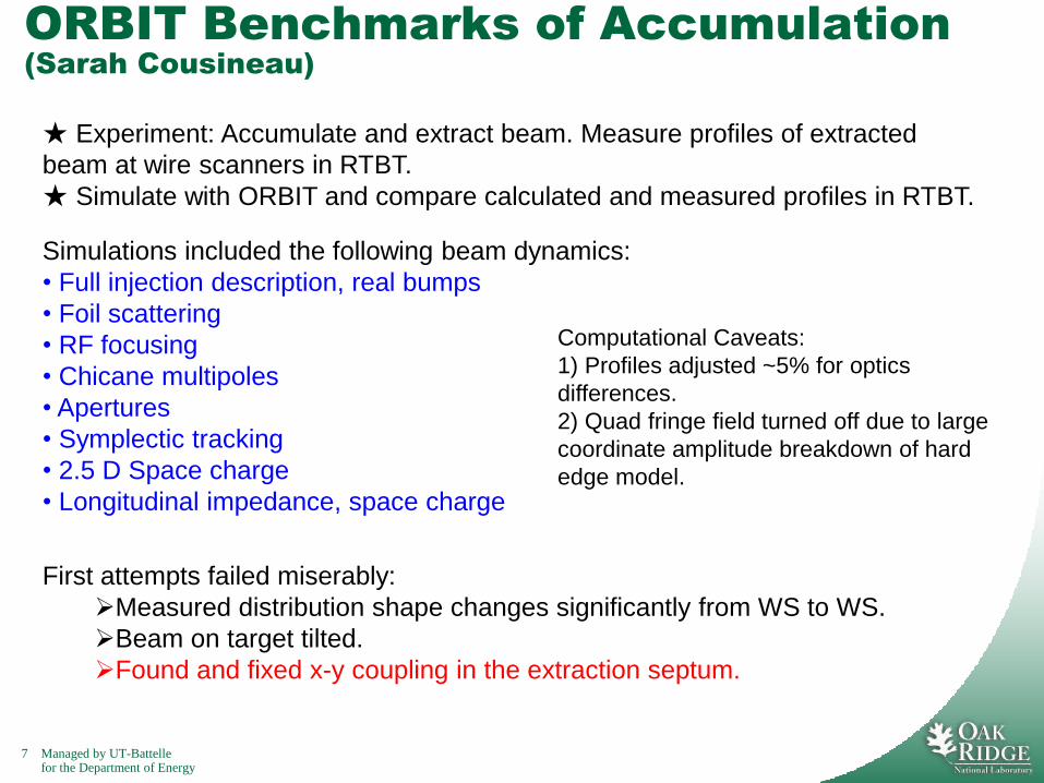
ORBIT Benchmarks of Accumulation
(Sarah Cousineau)
Simulations included the following beam dynamics:
• Full injection description, real bumps
• Foil scattering
• RF focusing
• Chicane multipoles
• Apertures
• Symplectic tracking
• 2.5 D Space charge
• Longitudinal impedance, space charge
First attempts failed miserably:
Measured distribution shape changes significantly from WS to WS.
Beam on target tilted.
Found and fixed x-y coupling in the extraction septum.
★ Experiment: Accumulate and extract beam. Measure profiles of extracted
beam at wire scanners in RTBT.
★ Simulate with ORBIT and compare calculated and measured profiles in RTBT.
Computational Caveats:
1) Profiles adjusted ~5% for optics
differences.
2) Quad fringe field turned off due to large
coordinate amplitude breakdown of hard
edge model.
8 Managed by UT-Battellefor the Department of Energy
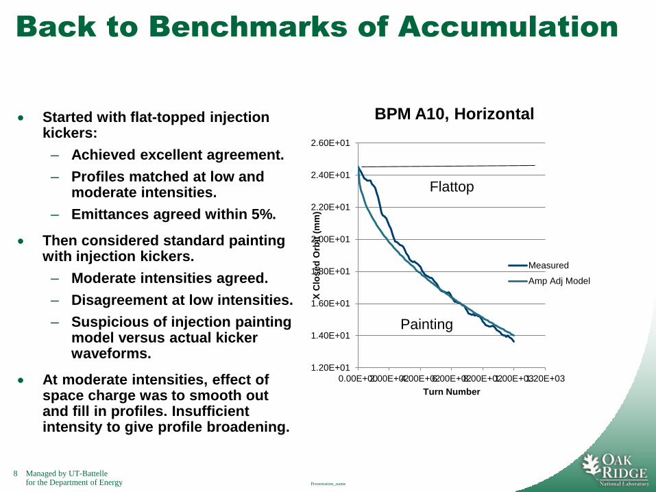
Back to Benchmarks of Accumulation
Started with flat-topped injection kickers:
– Achieved excellent agreement.
– Profiles matched at low and moderate intensities.
– Emittances agreed within 5%.
Then considered standard painting with injection kickers.
– Moderate intensities agreed.
– Disagreement at low intensities.
– Suspicious of injection painting model versus actual kicker waveforms.
At moderate intensities, effect of space charge was to smooth out and fill in profiles. Insufficient intensity to give profile broadening.
Presentation_name
1.20E+01
1.40E+01
1.60E+01
1.80E+01
2.00E+01
2.20E+01
2.40E+01
2.60E+01
0.00E+002.00E+024.00E+026.00E+028.00E+021.00E+031.20E+03
X C
losed
Orb
it (
mm
)
Turn Number
BPM A10, Horizontal
Measured
Amp Adj Model
Flattop
Painting
9 Managed by UT-Battellefor the Department of Energy
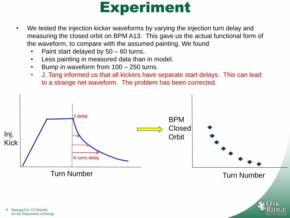
Experiment
• We tested the injection kicker waveforms by varying the injection turn delay and
measuring the closed orbit on BPM A13. This gave us the actual functional form of
the waveform, to compare with the assumed painting. We found
• Paint start delayed by 50 – 60 turns.
• Less painting in measured data than in model.
• Bump in waveform from 100 – 250 turns.
• J. Tang informed us that all kickers have separate start delays. This can lead
to a strange net waveform. The problem has been corrected.
N turns delay
Inj.
Kick
Turn Number
0 delayBPM
Closed
Orbit
Turn Number

10 Managed by UT-Battellefor the Department of Energy
8
9
10
11
12
13
14
15
16
17
18
0 200 400 600 800 1000 1200
Y C
losed
Orb
it (
mm
)
Turn Number
BPM A10, Vertical
Analytic
Data
1.20E+01
1.40E+01
1.60E+01
1.80E+01
2.00E+01
2.20E+01
2.40E+01
2.60E+01
0.00E+00 2.00E+02 4.00E+02 6.00E+02 8.00E+02 1.00E+03 1.20E+03
X C
losed
Orb
it (
mm
)
Turn Number
BPM A10, Horizontal
Measured
Amp Adj Model
Measured Oct. 2009.
~80us timing offset
corrected in both
planes.
Measured kicker
waveforms were used
in ORBIT simulations.
Back to Benchmarks Again
11 Managed by UT-Battellefor the Department of Energy
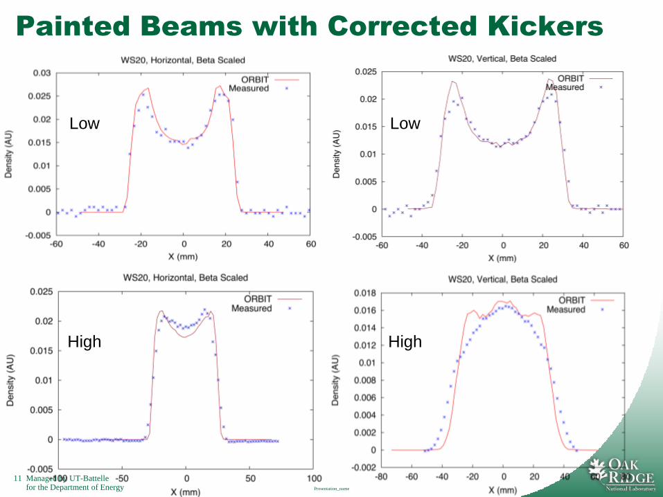
Painted Beams with Corrected Kickers
Presentation_name
Low
High
Low
High
12 Managed by UT-Battellefor the Department of Energy
Summary of Results
Progress Report:
Flattop, low intensity, both planes
Flattop, high intensity, both planes
Painted, low intensity, both planes
Painted, high intensity, Horizontal
X Painted, high intensity, Vertical.
X This is now under study, but it appears that the profiles are sensitive to the beam intensity. Also, Qx ≈ Qy, so there could be some x-y coupling.
13 Managed by UT-Battellefor the Department of Energy
Ring Beam Dynamics Progress January 22-24, 2008
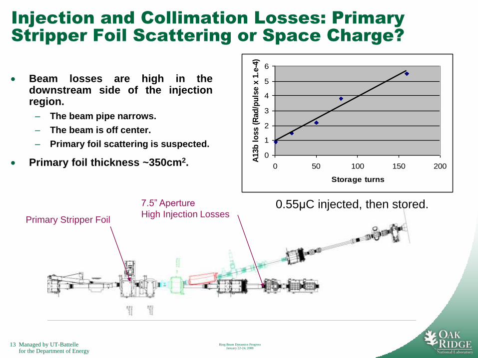
Injection and Collimation Losses: Primary
Stripper Foil Scattering or Space Charge?
Beam losses are high in thedownstream side of the injectionregion.
– The beam pipe narrows.
– The beam is off center.
– Primary foil scattering is suspected.
Primary foil thickness ~350cm2.
7.5” Aperture
High Injection LossesPrimary Stripper Foil
0
1
2
3
4
5
6
0 50 100 150 200
Storage turns
A13b
lo
ss (
Rad
/pu
lse x
1.e
-4)
0.55μC injected, then stored.

14 Managed by UT-Battellefor the Department of Energy
Ring Beam Dynamics Progress January 22-24, 2008
Injection Region: Beam is Off Center
Experimental studies:
– Steer toward center using chicane dipoles
– Steer toward center using injection kickers
– Perform studies both with flat-topped and painted beams
Simulate using ORBIT
Quad Doublet
KickerChicane bend
Aperture restriction
End Quad Doublet
At Kicker
15 Managed by UT-Battellefor the Department of Energy
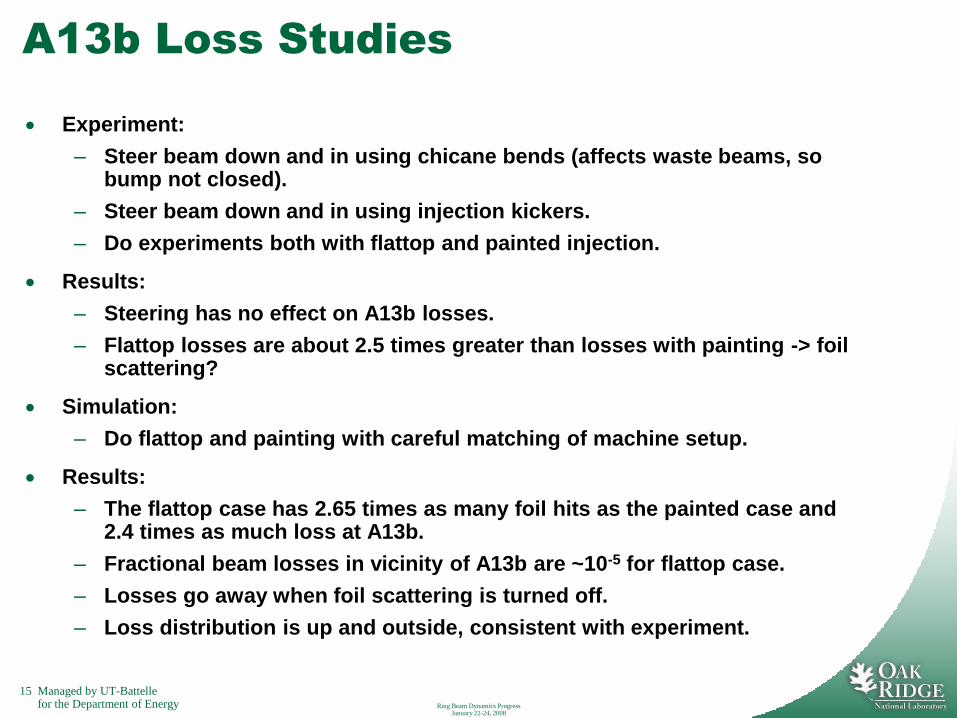
A13b Loss Studies
Experiment:
– Steer beam down and in using chicane bends (affects waste beams, so bump not closed).
– Steer beam down and in using injection kickers.
– Do experiments both with flattop and painted injection.
Results:
– Steering has no effect on A13b losses.
– Flattop losses are about 2.5 times greater than losses with painting -> foil scattering?
Simulation:
– Do flattop and painting with careful matching of machine setup.
Results:
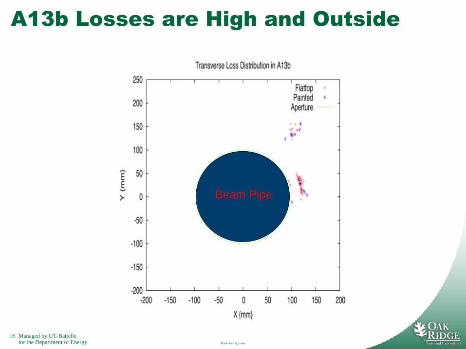
– The flattop case has 2.65 times as many foil hits as the painted case and 2.4 times as much loss at A13b.
– Fractional beam losses in vicinity of A13b are ~10-5 for flattop case.
– Losses go away when foil scattering is turned off.
– Loss distribution is up and outside, consistent with experiment.
Ring Beam Dynamics Progress January 22-24, 2008
16 Managed by UT-Battellefor the Department of Energy
A13b Losses are High and Outside
Presentation_name
Beam Pipe
17 Managed by UT-Battellefor the Department of Energy
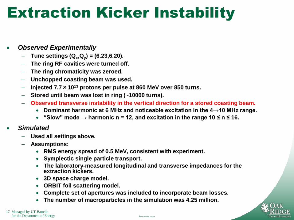
Extraction Kicker Instability
Observed Experimentally
– Tune settings (Qx,Qy) = (6.23,6.20).
– The ring RF cavities were turned off.
– The ring chromaticity was zeroed.
– Unchopped coasting beam was used.
– Injected 7.7×10¹³ protons per pulse at 860 MeV over 850 turns.
– Stored until beam was lost in ring (~10000 turns).
– Observed transverse instability in the vertical direction for a stored coasting beam.
Dominant harmonic at 6 MHz and noticeable excitation in the 4→10 MHz range.
“Slow” mode → harmonic n = 12, and excitation in the range 10 ≤ n ≤ 16.
Simulated
– Used all settings above.
– Assumptions:
RMS energy spread of 0.5 MeV, consistent with experiment.
Symplectic single particle transport.
The laboratory-measured longitudinal and transverse impedances for the extraction kickers.
3D space charge model.
ORBIT foil scattering model.
Complete set of apertures was included to incorporate beam losses.
The number of macroparticles in the simulation was 4.25 million.
Presentation_name
18 Managed by UT-Battellefor the Department of Energy Ring Beam Dynamics Progress
January 22-24, 2008
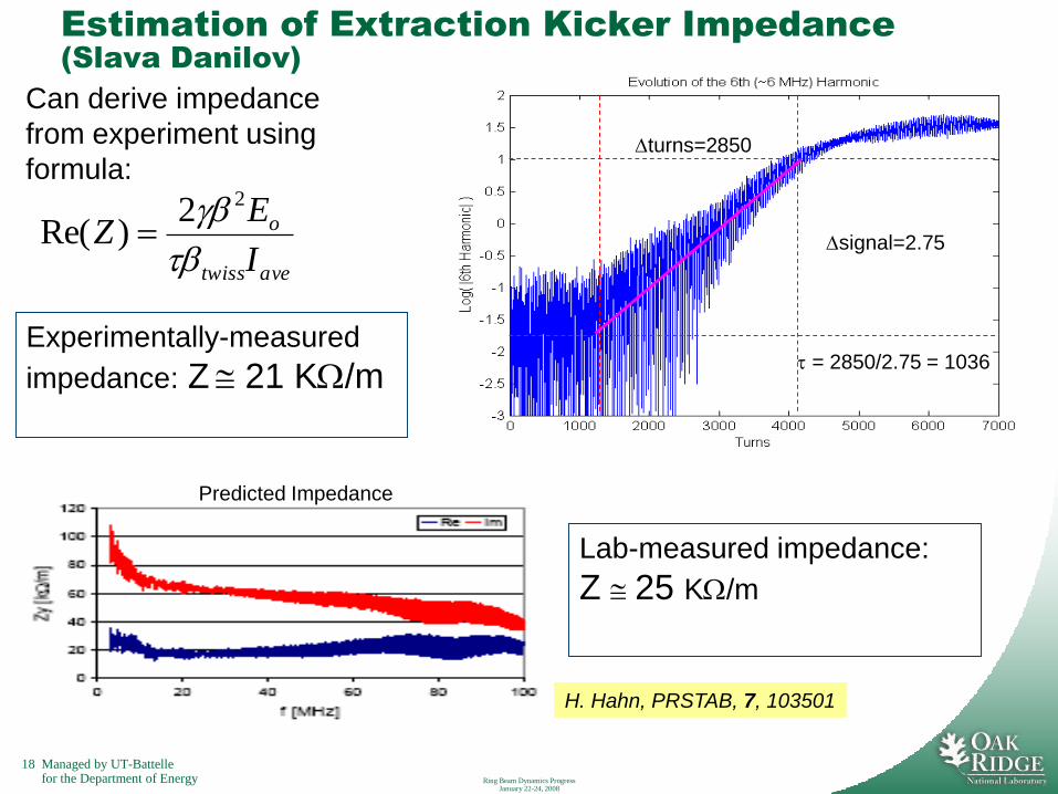
Estimation of Extraction Kicker Impedance
(Slava Danilov)
turns=2850
signal=2.75
avetwiss
o
I
EZ
22)Re(
Can derive impedance
from experiment using
formula:
Experimentally-measured
impedance: Z 21 K/m = 2850/2.75 = 1036
Lab-measured impedance:
Z 25 K/m
H. Hahn, PRSTAB, 7, 103501
Predicted Impedance
19 Managed by UT-Battellefor the Department of Energy
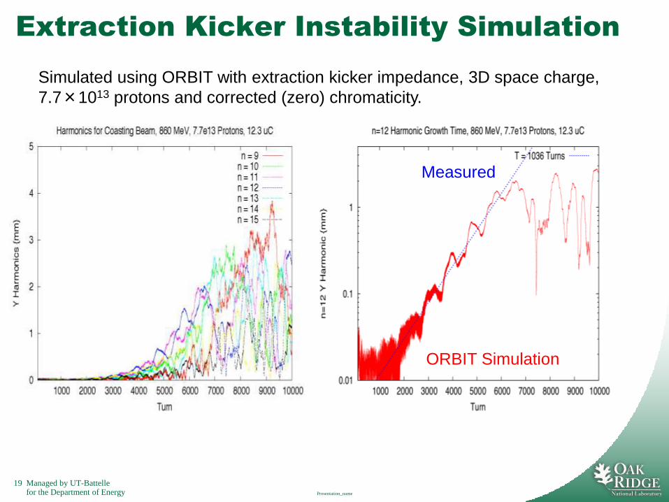
Extraction Kicker Instability Simulation
Presentation_name
Simulated using ORBIT with extraction kicker impedance, 3D space charge,
7.7×10¹³ protons and corrected (zero) chromaticity.
ORBIT Simulation
Measured
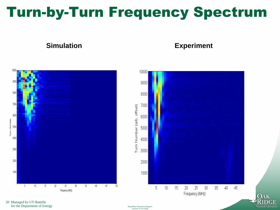
20 Managed by UT-Battellefor the Department of Energy Ring Beam Dynamics Progress
January 22-24, 2008
Turn-by-Turn Frequency Spectrum
Simulation Experiment
21 Managed by UT-Battellefor the Department of Energy
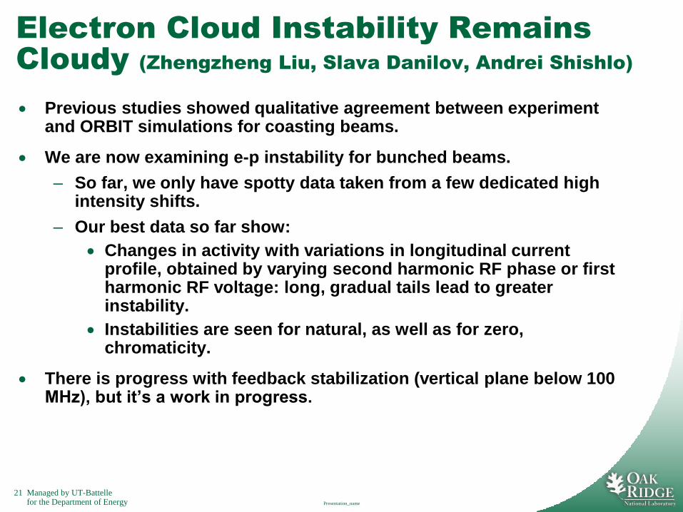
Electron Cloud Instability Remains
Cloudy (Zhengzheng Liu, Slava Danilov, Andrei Shishlo)
Previous studies showed qualitative agreement between experiment and ORBIT simulations for coasting beams.
We are now examining e-p instability for bunched beams.
– So far, we only have spotty data taken from a few dedicated high intensity shifts.
– Our best data so far show:
Changes in activity with variations in longitudinal current profile, obtained by varying second harmonic RF phase or first harmonic RF voltage: long, gradual tails lead to greater instability.
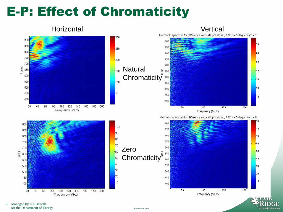
Instabilities are seen for natural, as well as for zero, chromaticity.
There is progress with feedback stabilization (vertical plane below 100 MHz), but it’s a work in progress.
Presentation_name
22 Managed by UT-Battellefor the Department of Energy
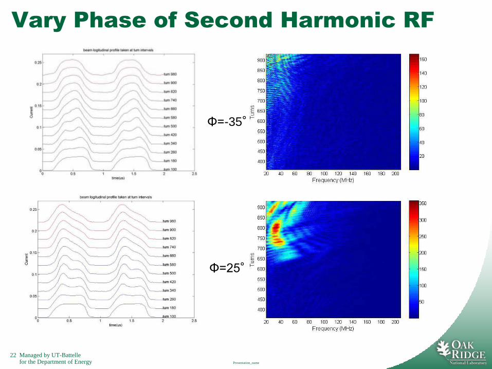
Vary Phase of Second Harmonic RF
Presentation_name
Φ=-35°
Φ=25°
23 Managed by UT-Battellefor the Department of Energy Ring Beam Dynamics Progress
January 22-24, 2008
Status of the ORBIT Code
ORBIT serves as our workhorse code for ring simulation:– Benchmark accumulation, storage, and transport.
– Study various loss mechanisms.
– Impedance-driven and electron cloud instabilities.
– Electron collection at stripper foil.
– …
We continue to make incremental improvements to the various modules: now working on time dependent magnets and internal lattice function calculations.
More people are using ORBIT, both in the US and abroad.
New model development is being carried out in pyORBIT (Andrei Shishlo):
– Laser stripping dynamical model (Timofey Gorlov).
– Porting existing ORBIT models to pyORBIT goes slowly. We hope to get more support for the work.
24 Managed by UT-Battellefor the Department of Energy
Summary
Understanding SNS ring beam dynamics requires experiment, theory, simulation, and great care.
There is good agreement between simulated and experimental results, and it gets better as we refine our understanding of the ring.
Benchmarking has already allowed us to identify hardware problems, including:
– Significant x-y coupling in the original ring extraction septum magnet.
– Improper performance of the injection kicker painting waveforms.
Successful benchmarks include:
– Ring injection process at low and medium intensities.
– Losses at A13b.
– The extraction kicker impedance instability.
We are gathering e-p instability data during dedicated high intensity shifts.
– This data shows systematic variation of e-p activity with longitudinal beam profile, controlled by varying the relative phases of the ring RF cavities.
We continue to support and develop ORBIT, which is used at an increasing number of labs.
Ring Beam Dynamics Progress January 22-24, 2008

25 Managed by UT-Battellefor the Department of Energy
Supplemental Material Follows:
Presentation_name
26 Managed by UT-Battellefor the Department of Energy
Overview
SNS progresses toward full power of 1.44 MW.
– SNS has run at 865 kW during production with low losses.
– Current energy 930 MeV nearly 1014 protons on target perpulse.
– We have injected, stably accumulated, extracted, andtransported 1.551014 protons (24.8 C) to the target. TheSNS ring has now exceeded the design intensity of 1.51014
protons per pulse.
– However, losses at high intensity continue to present achallenge and instabilities lurk nearby.
In order to achieve acceptable losses and to avoid instabilitiesas we increase the beam intensity, we continue to enhance ourunderstanding of the underlying beam dynamics. This requiresexperimental study, theoretical insight, and painstakingcomputational benchmarking.
Presentation_name
27 Managed by UT-Battellefor the Department of Energy Ring Beam Dynamics Progress
January 22-24, 2008
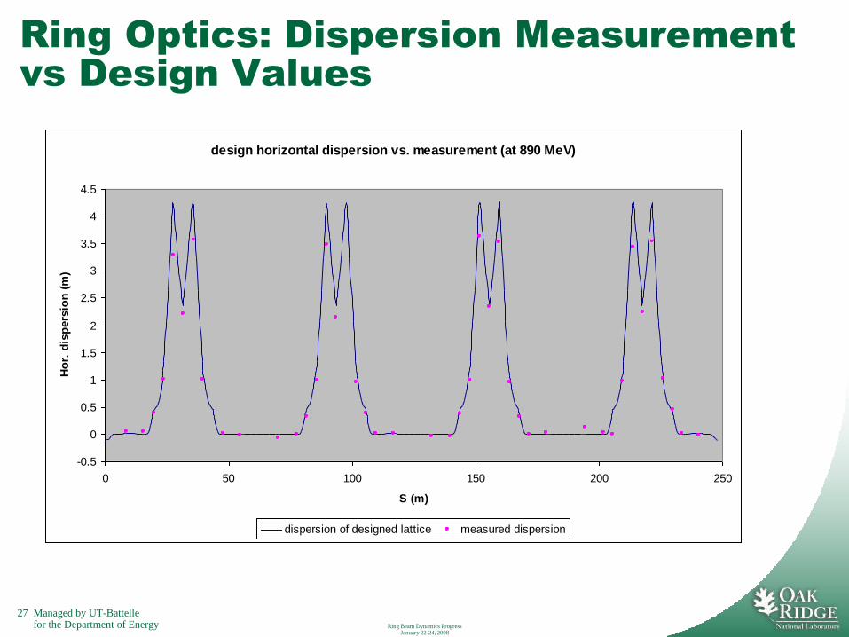
Ring Optics: Dispersion Measurement
vs Design Values
design horizontal dispersion vs. measurement (at 890 MeV)
-0.5
0
0.5
1
1.5
2
2.5
3
3.5
4
4.5
0 50 100 150 200 250
S (m)
Ho
r. d
isp
ers
ion
(m
)
dispersion of designed lattice measured dispersion
28 Managed by UT-Battellefor the Department of Energy
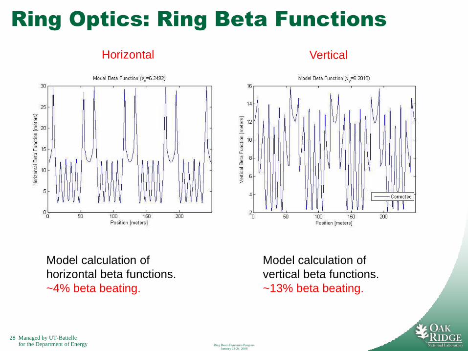
Ring Optics: Ring Beta Functions
Ring Beam Dynamics Progress January 22-24, 2008
Model calculation of
horizontal beta functions.
~4% beta beating.
Model calculation of
vertical beta functions.
~13% beta beating.
Horizontal Vertical
29 Managed by UT-Battellefor the Department of Energy
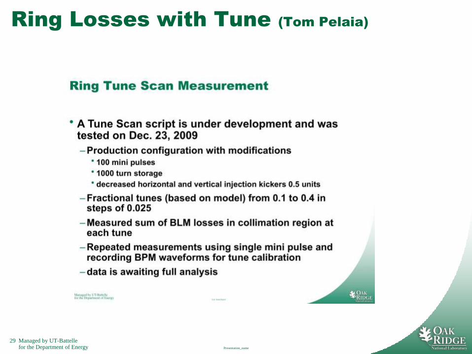
Ring Losses with Tune (Tom Pelaia)
Presentation_name

30 Managed by UT-Battellefor the Department of Energy
Back to Benchmarks of Accumulation
Computational caveats:
Corrected the ORBIT profiles for measured RTBT optics differences on
the order of ≤5% in beam size.
Also shut off quad fringe field effects because they caused
unrealistically large horizontal emittance growth due to off-axis tracking in
injection straight.
We returned to benchmarks of accumulation with the corrected extraction
septum.
Started with flat-topped injection kickers (no painting).
Varied intensities 8.61012 (80 turns) 5.31013 (460 turns) ppp.
Results agreed very well.
Then considered standard painting with injection kickers.
640 turns.
Varied intensities 8.21012 7.51013 ppp.

31 Managed by UT-Battellefor the Department of Energy
Low and High Intensity Flat-top Beams
Low
High
Low
High

32 Managed by UT-Battellefor the Department of Energy
Low and High Intensity Painted Beams
Low
High
Low
High
33 Managed by UT-Battellefor the Department of Energy
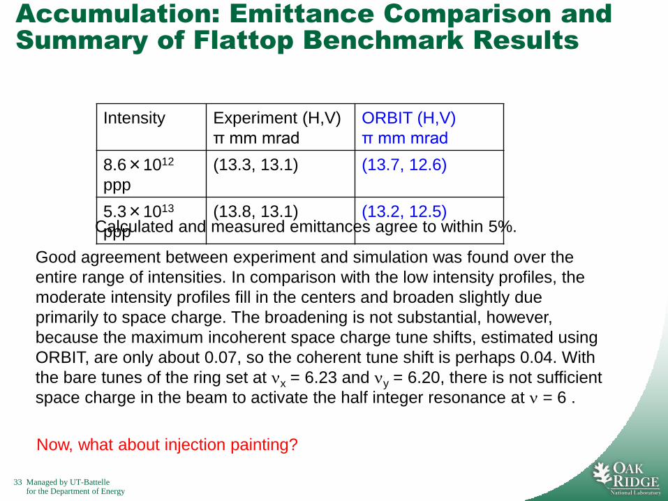
Accumulation: Emittance Comparison and
Summary of Flattop Benchmark Results
Good agreement between experiment and simulation was found over the
entire range of intensities. In comparison with the low intensity profiles, the
moderate intensity profiles fill in the centers and broaden slightly due
primarily to space charge. The broadening is not substantial, however,
because the maximum incoherent space charge tune shifts, estimated using
ORBIT, are only about 0.07, so the coherent tune shift is perhaps 0.04. With
the bare tunes of the ring set at x = 6.23 and y = 6.20, there is not sufficient
space charge in the beam to activate the half integer resonance at = 6 .
Now, what about injection painting?
Intensity Experiment (H,V)
π mm mrad
ORBIT (H,V)
π mm mrad
8.6×10¹²
ppp
(13.3, 13.1) (13.7, 12.6)
5.3×10¹³
ppp
(13.8, 13.1) (13.2, 12.5)Calculated and measured emittances agree to within 5%.
34 Managed by UT-Battellefor the Department of Energy
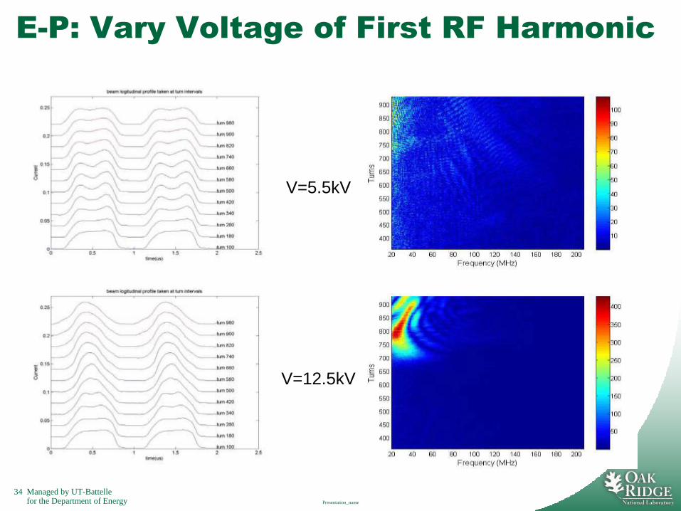
E-P: Vary Voltage of First RF Harmonic
Presentation_name
V=5.5kV
V=12.5kV
35 Managed by UT-Battellefor the Department of Energy
E-P: Effect of Chromaticity
Presentation_name
Natural
Chromaticity
Zero
Chromaticity
Horizontal Vertical
36 Managed by UT-Battellefor the Department of Energy
Detailed Summary
Understanding SNS ring beam dynamics requires experiment, theory, simulation, and great care.
Benchmarking has already allowed us to identify hardware problems, including:
– Significant x-y coupling in the original ring extraction septum magnet.
– Improper performance of the injection kicker painting waveforms.
There is good agreement between simulated and experimental results.
We have benchmarked the ring injection process at low and medium intensities.
– In these cases, the main effect of space charge is to fill in the hollow central region of the beam.
– So far, the space charge tune shifts are insufficient to cause beam broadening through the half integer resonance.
We have also completed a careful benchmark of the extraction kicker impedance instability.
– The calculated and experimental growth rates are in perfect agreement.
– Comparison of the spectral evolution of the experiment and simulation out to 10000 turns shows qualitatively similar results. However, the detailed evolution in the nonlinear stage of the instability after 5000 turns is somewhat different.
We are gathering e-p instability data during dedicated high intensity shifts.
– This data shows systematic variation of e-p activity with longitudinal beam profile, controlled by varying the relative phases of the ring RF cavities.
We continue to support and develop ORBIT, which is used at an increasing number of labs.
Ring Beam Dynamics Progress January 22-24, 2008