Embed Size (px)
Citation preview
RIGGING EQUIPMENTREFERENCE BOOK
2
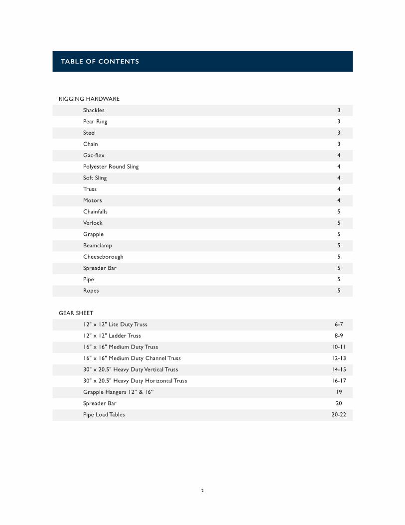
RIGGING HARDWARE
Shackles 3
Pear Ring 3
Steel 3
Chain 3
Gac-flex 4
Polyester Round Sling 4
Soft Sling 4
Truss 4
Motors 4
Chainfalls 5
Verlock 5
Grapple 5
Beamclamp 5
Cheeseborough 5
Spreader Bar 5
Pipe 5
Ropes 5
GEAR SHEET
12" x 12" Lite Duty Truss 6-7
12" x 12" Ladder Truss 8-9
16" x 16" Medium Duty Truss 10-11
16" x 16" Medium Duty Channel Truss 12-13
30" x 20.5" Heavy Duty Vertical Truss 14-15
30" x 20.5" Heavy Duty Horizontal Truss 16-17
Grapple Hangers 12” & 16” 19
Spreader Bar 20
Pipe Load Tables 20-22
TABLE OF CONTENTS
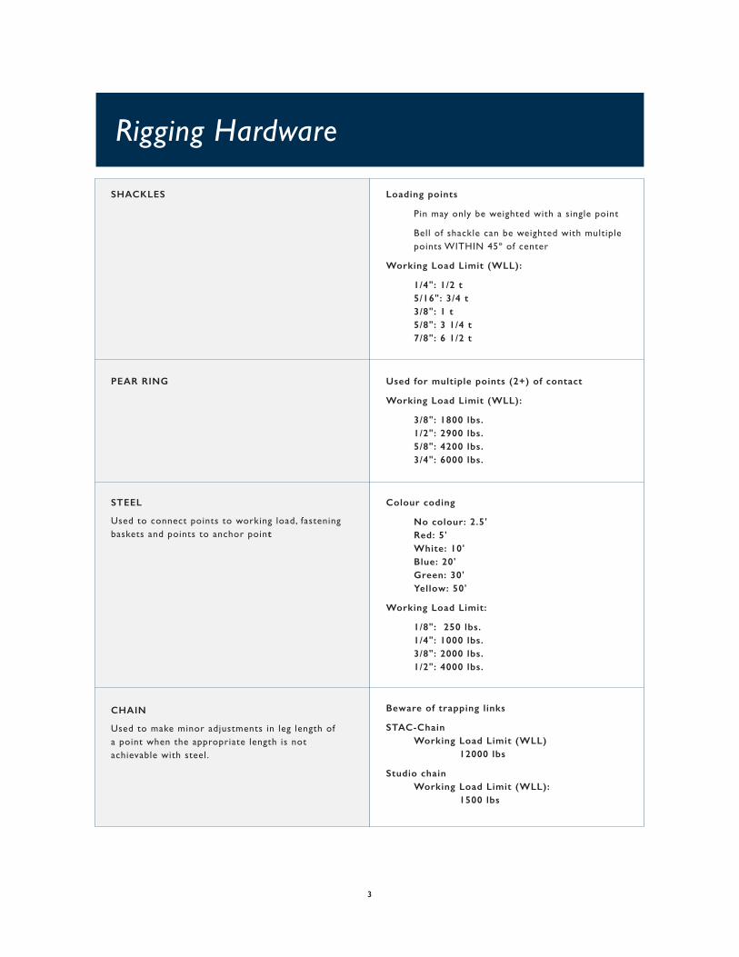
Beware of trapping links
STAC-Chain Working Load Limit (WLL) 12000 lbs
Studio chain Working Load Limit (WLL): 1500 lbs
SHACKLES Loading points
Pin may only be weighted with a single point
Bell of shackle can be weighted with multiple points WITHIN 45º of center
Working Load Limit (WLL):
1/4": 1/2 t 5/16": 3/4 t 3/8": 1 t 5/8": 3 1/4 t 7/8": 6 1/2 t
PEAR RING Used for multiple points (2+) of contact
Working Load Limit (WLL):
3/8": 1800 lbs. 1/2": 2900 lbs. 5/8": 4200 lbs. 3/4": 6000 lbs.
STEEL
Used to connect points to working load, fasteningbaskets and points to anchor point
Colour coding
No colour: 2.5' Red: 5' White: 10' Blue: 20' Green: 30' Yellow: 50'
Working Load Limit:
1/8": 250 lbs. 1/4": 1000 lbs. 3/8": 2000 lbs. 1/2": 4000 lbs.
CHAIN
Used to make minor adjustments in leg length of a point when the appropriate length is not achievable with steel.
Rigging Hardware
3
4
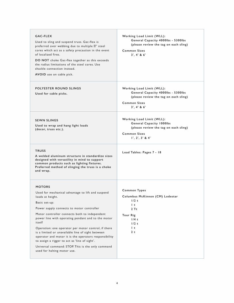
Working Load Limit (WLL): General Capacity 4000lbs - 5300lbs (please review the tag on each sling)
Common Sizes 3', 4' & 6'
Working Load Limit (WLL): General Capacity 4000lbs - 5300lbs (please review the tag on each sling)
Common Sizes 3', 4' & 6'
Working Load Limit (WLL): General Capacity 1000lbs (please review the tag on each sling)
Common Sizes 1', 2', 3' & 4'
Load Tables: Pages 7 - 18
Common Types
Columbus McKinnon (CM) Lodestar 1/2 t 1 t 2 Tt
Tour Rig 1/4 t 1/2 t 1 t 2 t
POLYESTER ROUND SLINGS
Used for cable picks.
SEWN SLINGS
Used to wrap and hang light loads(decor, truss etc.).
TRUSS
A welded aluminum structure in standardize sizes designed with versatility in mind to support common products such as lighting fixtures. Preferred method of slinging the truss is a choke and wrap.
GAC-FLEX
Used to sling and suspend truss. Gac-flex is preferred over webbing due to multiple �” steel cores which act as a safety precaution in the event of localized fires.
DO NOT choke Gac-flex together as this exceeds the radius l imitations of the steel cores. Use shackle connection instead.
AVOID use on cable pick.
MOTORS
Used for mechanical advantage to lift and suspend loads at height.
Basic set-up:
Power supply connects to motor controller
Motor controller connects both to independent power line with operating pendant and to the motor itself
Operation: one operator per motor control, i f there is a l imited or unavailable l ine of sight between operator and motor it is the operators responsibil ity to assign a rigger to act as ‘ l ine of sight’.
Universal command: STOP. This is the only command used for halting motor use.
5
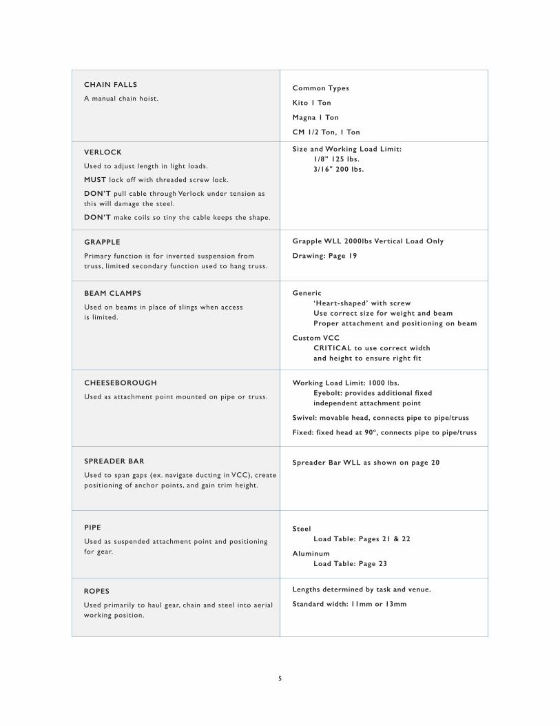
Common Types
Kito 1 Ton
Magna 1 Ton
CM 1/2 Ton, 1 Ton
CHAIN FALLS
A manual chain hoist.
Size and Working Load Limit: 1/8" 125 lbs. 3/16" 200 lbs.
Spreader Bar WLL as shown on page 20
Grapple WLL 2000lbs Vertical Load Only
Drawing: Page 19
Generic ‘Heart-shaped’ with screw Use correct size for weight and beam Proper attachment and positioning on beam
Custom VCC CRITICAL to use correct width and height to ensure right fit
VERLOCK
Used to adjust length in l ight loads.
MUST lock off with threaded screw lock.
DON’T pull cable through Verlock under tension as this will damage the steel.
DON’T make coils so tiny the cable keeps the shape.
GRAPPLE
Primary function is for inverted suspension from truss, l imited secondary function used to hang truss.
BEAM CLAMPS
Used on beams in place of slings when access is l imited.
CHEESEBOROUGH
Used as attachment point mounted on pipe or truss.
Working Load Limit: 1000 lbs. Eyebolt: provides additional fixed independent attachment point
Swivel: movable head, connects pipe to pipe/truss
Fixed: fixed head at 90º, connects pipe to pipe/truss
Lengths determined by task and venue.
Standard width: 11mm or 13mm
SPREADER BAR
Used to span gaps (ex. navigate ducting in VCC), create positioning of anchor points, and gain trim height.
Steel Load Table: Pages 21 & 22
Aluminum Load Table: Page 23
PIPE
Used as suspended attachment point and positioning for gear.
ROPES
Used primarily to haul gear, chain and steel into aerial working position.
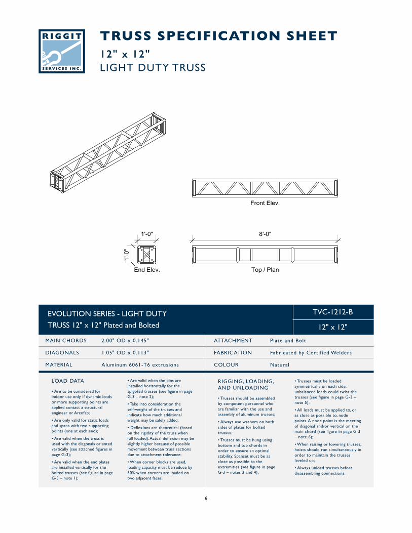
TRUSS SPECIFICATION SHEET12" x 12"LIGHT DUTY TRUSS
EVOLUTION SERIES - LIGHT DUTY
TRUSS 12" x 12" Plated and Bolted
MAIN CHORDS 2.00" OD x 0.145"
DIAGONALS 1.05" OD x 0.113"
MATERIAL Aluminum 6061-T6 extrusions
ATTACHMENT Plate and Bolt
FABRICATION Fabricated by Certif ied Welders
COLOUR Natural
TVC-1212-B
12" x 12"
RIGGING, LOADING,AND UNLOADING
• Trusses should be assembled by competent personnel who are familiar with the use and assembly of aluminum trusses;
• Always use washers on both sides of plates for bolted trusses;
• Trusses must be hung using bottom and top chords in order to ensure an optimal stability. Spanset must be as close as possible to the extremities (see figure in page G-3 – notes 3 and 4);
• Are valid when the pins are installed horizontally for the spigoted trusses (see figure in page G-3 – note 2);
• Take into consideration the self-weight of the trusses and indicate how much additional weight may be safely added;
• Deflexions are theoretical (based on the rigidity of the truss when full loaded). Actual deflexion may be slightly higher because of possible movement between truss sections due to attachment tolerance;
• When corner blocks are used, loading capacity must be reduce by 50% when corners are loaded on two adjacent faces.
• Trusses must be loaded symmetrically on each side; unbalanced loads could twist the trusses (see figure in page G-3 – note 5);
• All loads must be applied to, or as close as possible to, node points. A node point is the meeting of diagonal and/or vertical on the main chord (see figure in page G-3 – note 6);
• When raising or lowering trusses, hoists should run simultaneously in order to maintain the trusses leveled up;
• Always unload trusses before disassembling connections.
LOAD DATA
• Are to be considered for indoor use only. If dynamic loads or more supporting points are applied contact a structural engineer or Arcofab;
• Are only valid for static loads and spans with two supporting points (one at each end);
• Are valid when the truss is used with the diagonals oriented vertically (see attached figures in page G-3);
• Are valid when the end plates are installed vertically for the bolted trusses (see figure in page G-3 – note 1);
6
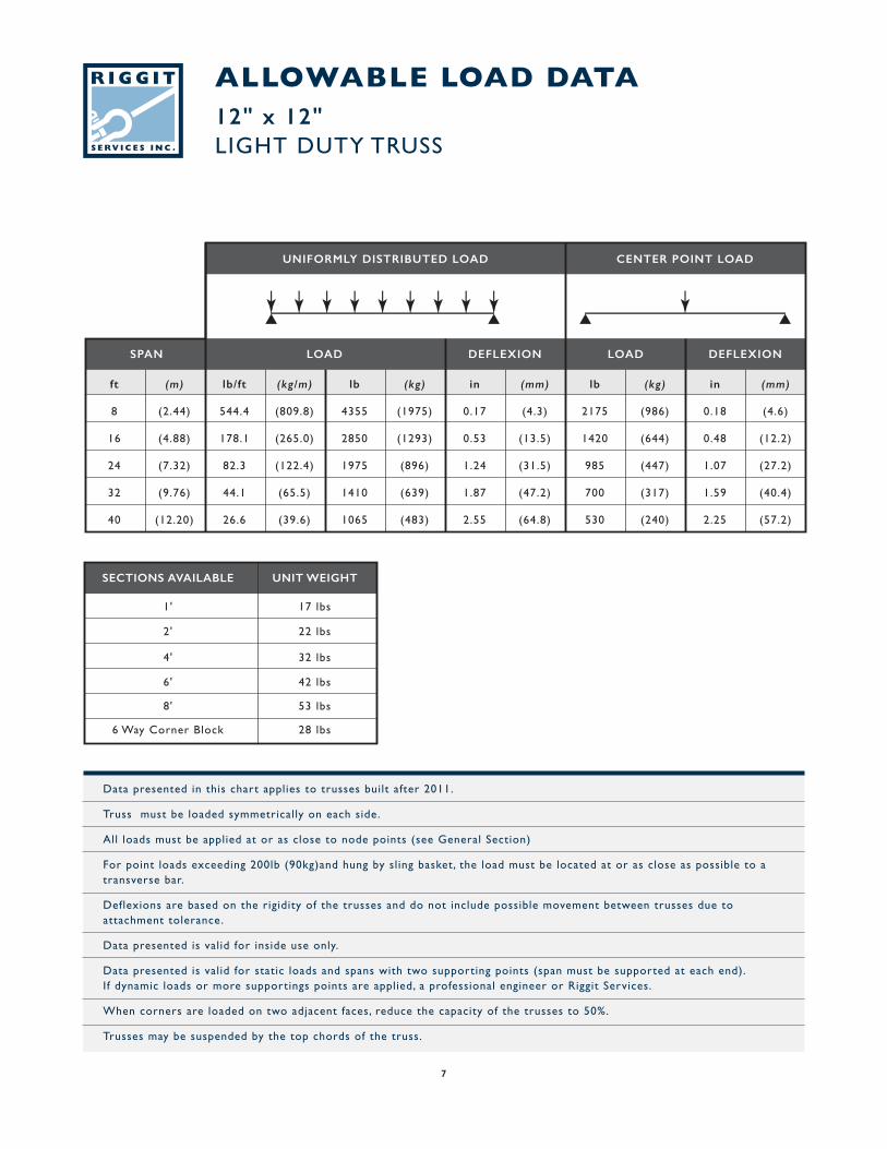
ALLOWABLE LOAD DATA12" x 12"LIGHT DUTY TRUSS
Data presented in this chart applies to trusses built after 2011.
Truss must be loaded symmetrically on each side.
All loads must be applied at or as close to node points (see General Section)
For point loads exceeding 200lb (90kg)and hung by sling basket, the load must be located at or as close as possible to a transverse bar.
Deflexions are based on the rigidity of the trusses and do not include possible movement between trusses due to attachment tolerance.
Data presented is valid for inside use only.
Data presented is valid for static loads and spans with two supporting points (span must be supported at each end). If dynamic loads or more supportings points are applied, a professional engineer or Riggit Services.
When corners are loaded on two adjacent faces, reduce the capacity of the trusses to 50%.
Trusses may be suspended by the top chords of the truss.
ft (m) lb/ft (kg/m) lb (kg) in (mm) lb (kg) in (mm)
8 (2.44) 544.4 (809.8) 4355 (1975) 0.17 (4.3) 2175 (986) 0.18 (4.6)
16 (4.88) 178.1 (265.0) 2850 (1293) 0.53 (13.5) 1420 (644) 0.48 (12.2)
24 (7.32) 82.3 (122.4) 1975 (896) 1.24 (31.5) 985 (447) 1.07 (27.2)
32 (9.76) 44.1 (65.5) 1410 (639) 1.87 (47.2) 700 (317) 1.59 (40.4)
40 (12.20) 26.6 (39.6) 1065 (483) 2.55 (64.8) 530 (240) 2.25 (57.2)
SPAN LOAD DEFLEXION DEFLEXIONLOAD
UNIFORMLY DISTRIBUTED LOAD CENTER POINT LOAD
SECTIONS AVAILABLE UNIT WEIGHT
17 lbs1'
22 lbs2'
32 lbs4'
42 lbs6'
53 lbs8'
28 lbs6 Way Corner Block
7
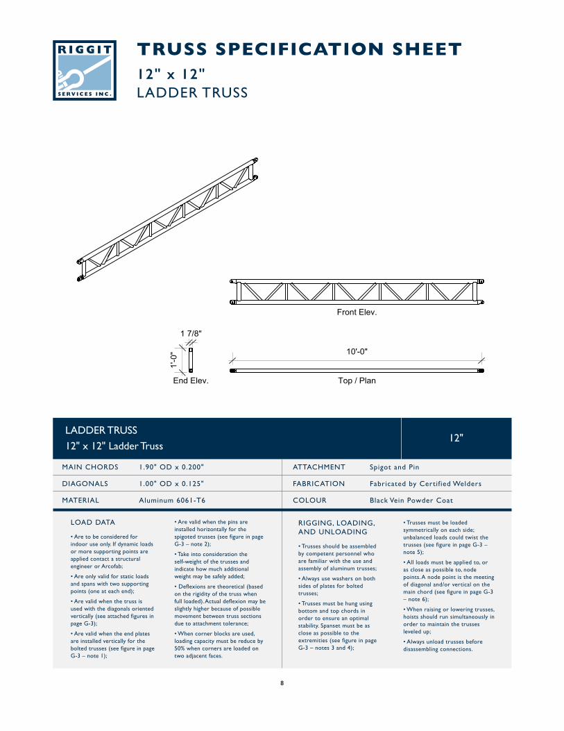
TRUSS SPECIFICATION SHEET12" x 12"LADDER TRUSS
LADDER TRUSS
12" x 12" Ladder Truss
MAIN CHORDS 1.90" OD x 0.200"
DIAGONALS 1.00" OD x 0.125"
MATERIAL Aluminum 6061-T6
ATTACHMENT Spigot and Pin
FABRICATION Fabricated by Certif ied Welders
COLOUR Black Vein Powder Coat
12"
RIGGING, LOADING,AND UNLOADING
• Trusses should be assembled by competent personnel who are familiar with the use and assembly of aluminum trusses;
• Always use washers on both sides of plates for bolted trusses;
• Trusses must be hung using bottom and top chords in order to ensure an optimal stability. Spanset must be as close as possible to the extremities (see figure in page G-3 – notes 3 and 4);
• Are valid when the pins are installed horizontally for the spigoted trusses (see figure in page G-3 – note 2);
• Take into consideration the self-weight of the trusses and indicate how much additional weight may be safely added;
• Deflexions are theoretical (based on the rigidity of the truss when full loaded). Actual deflexion may be slightly higher because of possible movement between truss sections due to attachment tolerance;
• When corner blocks are used, loading capacity must be reduce by 50% when corners are loaded on two adjacent faces.
• Trusses must be loaded symmetrically on each side; unbalanced loads could twist the trusses (see figure in page G-3 – note 5);
• All loads must be applied to, or as close as possible to, node points. A node point is the meeting of diagonal and/or vertical on the main chord (see figure in page G-3 – note 6);
• When raising or lowering trusses, hoists should run simultaneously in order to maintain the trusses leveled up;
• Always unload trusses before disassembling connections.
LOAD DATA
• Are to be considered for indoor use only. If dynamic loads or more supporting points are applied contact a structural engineer or Arcofab;
• Are only valid for static loads and spans with two supporting points (one at each end);
• Are valid when the truss is used with the diagonals oriented vertically (see attached figures in page G-3);
• Are valid when the end plates are installed vertically for the bolted trusses (see figure in page G-3 – note 1);
8
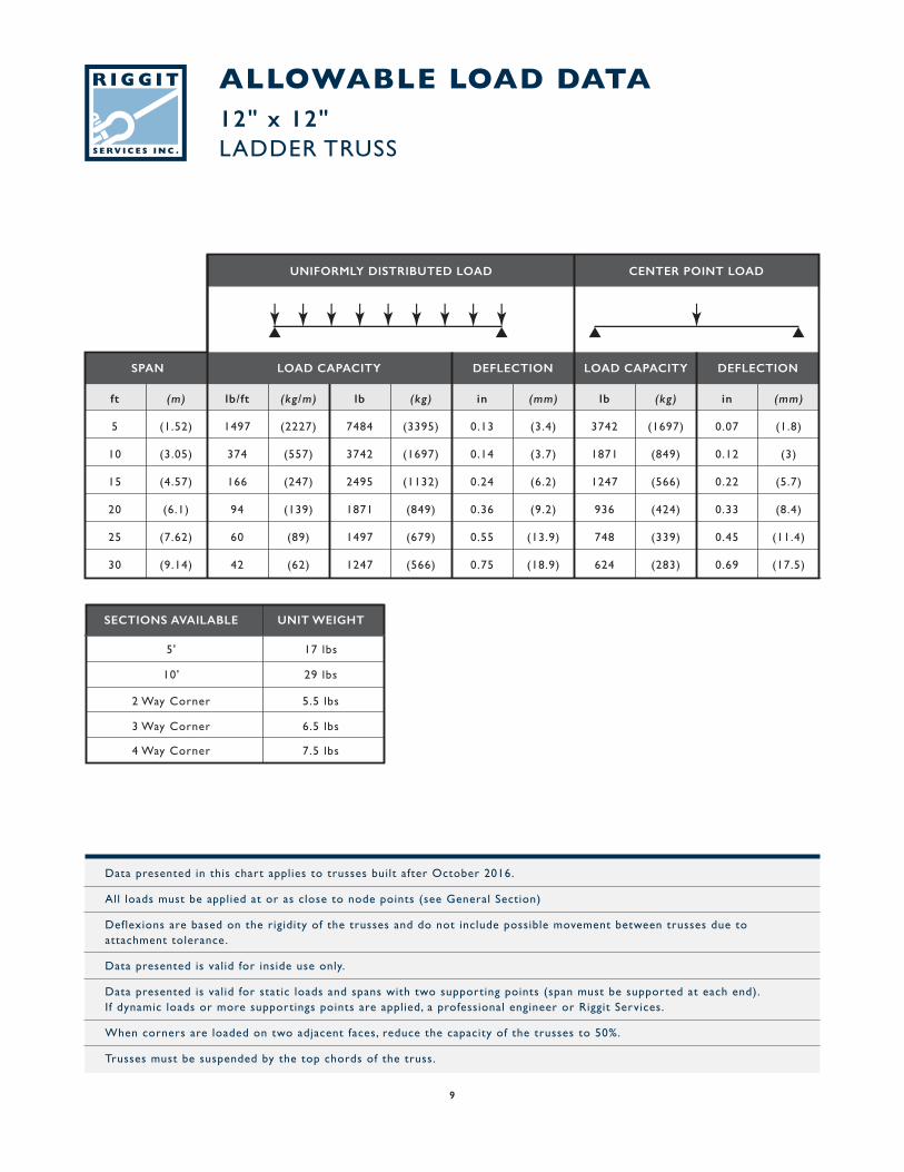
ALLOWABLE LOAD DATA12" x 12"LADDER TRUSS
Data presented in this chart applies to trusses built after October 2016.
All loads must be applied at or as close to node points (see General Section)
Deflexions are based on the rigidity of the trusses and do not include possible movement between trusses due to attachment tolerance.
Data presented is valid for inside use only.
Data presented is valid for static loads and spans with two supporting points (span must be supported at each end). If dynamic loads or more supportings points are applied, a professional engineer or Riggit Services.
When corners are loaded on two adjacent faces, reduce the capacity of the trusses to 50%.
Trusses must be suspended by the top chords of the truss.
SECTIONS AVAILABLE UNIT WEIGHT
17 lbs5'
29 lbs10'
5.5 lbs2 Way Corner
6.5 lbs3 Way Corner
7.5 lbs4 Way Corner
ft (m) lb/ft (kg/m) lb (kg) in (mm) lb (kg) in (mm)
5 (1.52) 1497 (2227) 7484 (3395) 0.13 (3.4) 3742 (1697) 0.07 (1.8)
10 (3.05) 374 (557) 3742 (1697) 0.14 (3.7) 1871 (849) 0.12 (3)
15 (4.57) 166 (247) 2495 (1132) 0.24 (6.2) 1247 (566) 0.22 (5.7)
20 (6.1) 94 (139) 1871 (849) 0.36 (9.2) 936 (424) 0.33 (8.4)
25 (7.62) 60 (89) 1497 (679) 0.55 (13.9) 748 (339) 0.45 (11.4)
30 (9.14) 42 (62) 1247 (566) 0.75 (18.9) 624 (283) 0.69 (17.5)
SPAN LOAD CAPACITY DEFLECTION DEFLECTIONLOAD CAPACITY
UNIFORMLY DISTRIBUTED LOAD CENTER POINT LOAD
9
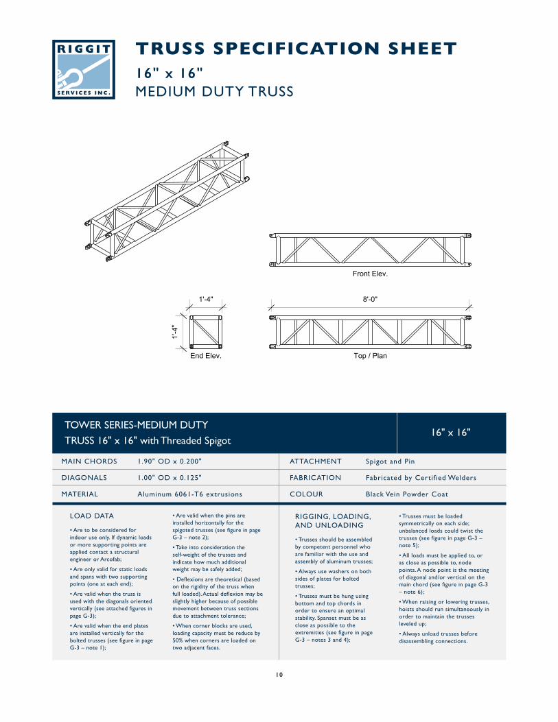
TRUSS SPECIFICATION SHEET16" x 16"MEDIUM DUTY TRUSS
TOWER SERIES-MEDIUM DUTY
TRUSS 16" x 16" with Threaded Spigot
MAIN CHORDS 1.90" OD x 0.200"
DIAGONALS 1.00" OD x 0.125"
MATERIAL Aluminum 6061-T6 extrusions
ATTACHMENT Spigot and Pin
FABRICATION Fabricated by Certif ied Welders
COLOUR Black Vein Powder Coat
16" x 16"
RIGGING, LOADING,AND UNLOADING
• Trusses should be assembled by competent personnel who are familiar with the use and assembly of aluminum trusses;
• Always use washers on both sides of plates for bolted trusses;
• Trusses must be hung using bottom and top chords in order to ensure an optimal stability. Spanset must be as close as possible to the extremities (see figure in page G-3 – notes 3 and 4);
• Are valid when the pins are installed horizontally for the spigoted trusses (see figure in page G-3 – note 2);
• Take into consideration the self-weight of the trusses and indicate how much additional weight may be safely added;
• Deflexions are theoretical (based on the rigidity of the truss when full loaded). Actual deflexion may be slightly higher because of possible movement between truss sections due to attachment tolerance;
• When corner blocks are used, loading capacity must be reduce by 50% when corners are loaded on two adjacent faces.
• Trusses must be loaded symmetrically on each side; unbalanced loads could twist the trusses (see figure in page G-3 – note 5);
• All loads must be applied to, or as close as possible to, node points. A node point is the meeting of diagonal and/or vertical on the main chord (see figure in page G-3 – note 6);
• When raising or lowering trusses, hoists should run simultaneously in order to maintain the trusses leveled up;
• Always unload trusses before disassembling connections.
LOAD DATA
• Are to be considered for indoor use only. If dynamic loads or more supporting points are applied contact a structural engineer or Arcofab;
• Are only valid for static loads and spans with two supporting points (one at each end);
• Are valid when the truss is used with the diagonals oriented vertically (see attached figures in page G-3);
• Are valid when the end plates are installed vertically for the bolted trusses (see figure in page G-3 – note 1);
10
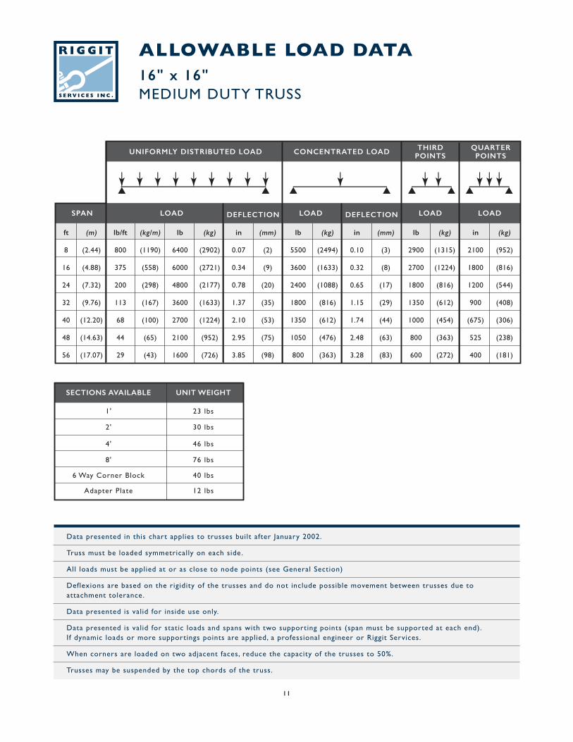
ALLOWABLE LOAD DATA16" x 16"MEDIUM DUTY TRUSS
ft (m) lb/ft (kg/m) lb (kg) in (mm) lb (kg) in (mm) lb (kg) in (kg)
8 (2.44) 800 (1190) 6400 (2902) 0.07 (2) 5500 (2494) 0.10 (3) 2900 (1315) 2100 (952)
16 (4.88) 375 (558) 6000 (2721) 0.34 (9) 3600 (1633) 0.32 (8) 2700 (1224) 1800 (816)
24 (7.32) 200 (298) 4800 (2177) 0.78 (20) 2400 (1088) 0.65 (17) 1800 (816) 1200 (544)
32 (9.76) 113 (167) 3600 (1633) 1.37 (35) 1800 (816) 1.15 (29) 1350 (612) 900 (408)
40 (12.20) 68 (100) 2700 (1224) 2.10 (53) 1350 (612) 1.74 (44) 1000 (454) (675) (306)
48 (14.63) 44 (65) 2100 (952) 2.95 (75) 1050 (476) 2.48 (63) 800 (363) 525 (238)
56 (17.07) 29 (43) 1600 (726) 3.85 (98) 800 (363) 3.28 (83) 600 (272) 400 (181)
SPAN LOAD DEFLECTIONDEFLECTION LOADLOADLOAD
UNIFORMLY DISTRIBUTED LOAD CONCENTRATED LOAD THIRDPOINTS
QUARTERPOINTS
Data presented in this chart applies to trusses built after January 2002.
Truss must be loaded symmetrically on each side.
All loads must be applied at or as close to node points (see General Section)
Deflexions are based on the rigidity of the trusses and do not include possible movement between trusses due to attachment tolerance.
Data presented is valid for inside use only.
Data presented is valid for static loads and spans with two supporting points (span must be supported at each end).If dynamic loads or more supportings points are applied, a professional engineer or Riggit Services.
When corners are loaded on two adjacent faces, reduce the capacity of the trusses to 50%.
Trusses may be suspended by the top chords of the truss.
SECTIONS AVAILABLE UNIT WEIGHT
23 lbs1'
30 lbs2'
46 lbs4'
76 lbs8'
40 lbs6 Way Corner Block
12 lbsAdapter Plate
11
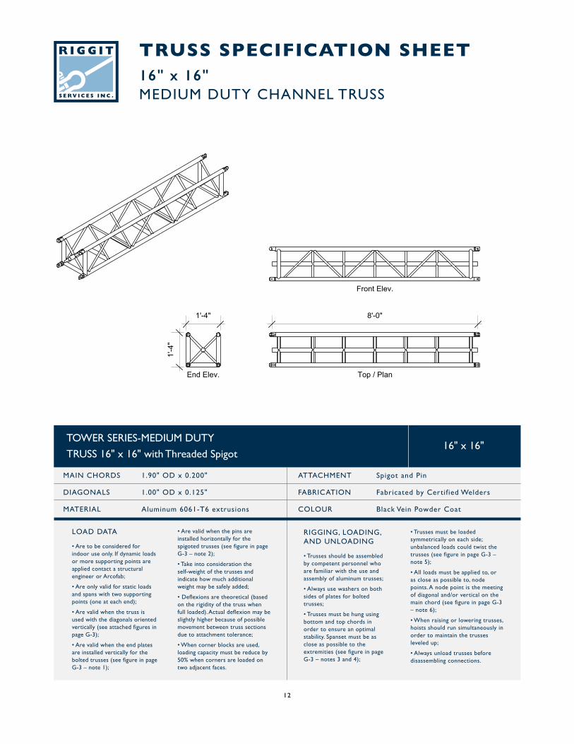
TRUSS SPECIFICATION SHEET16" x 16"MEDIUM DUTY CHANNEL TRUSS
TOWER SERIES-MEDIUM DUTY
TRUSS 16" x 16" with Threaded Spigot
MAIN CHORDS 1.90" OD x 0.200"
DIAGONALS 1.00" OD x 0.125"
MATERIAL Aluminum 6061-T6 extrusions
ATTACHMENT Spigot and Pin
FABRICATION Fabricated by Certif ied Welders
COLOUR Black Vein Powder Coat
16" x 16"
RIGGING, LOADING,AND UNLOADING
• Trusses should be assembled by competent personnel who are familiar with the use and assembly of aluminum trusses;
• Always use washers on both sides of plates for bolted trusses;
• Trusses must be hung using bottom and top chords in order to ensure an optimal stability. Spanset must be as close as possible to the extremities (see figure in page G-3 – notes 3 and 4);
• Are valid when the pins are installed horizontally for the spigoted trusses (see figure in page G-3 – note 2);
• Take into consideration the self-weight of the trusses and indicate how much additional weight may be safely added;
• Deflexions are theoretical (based on the rigidity of the truss when full loaded). Actual deflexion may be slightly higher because of possible movement between truss sections due to attachment tolerance;
• When corner blocks are used, loading capacity must be reduce by 50% when corners are loaded on two adjacent faces.
• Trusses must be loaded symmetrically on each side; unbalanced loads could twist the trusses (see figure in page G-3 – note 5);
• All loads must be applied to, or as close as possible to, node points. A node point is the meeting of diagonal and/or vertical on the main chord (see figure in page G-3 – note 6);
• When raising or lowering trusses, hoists should run simultaneously in order to maintain the trusses leveled up;
• Always unload trusses before disassembling connections.
LOAD DATA
• Are to be considered for indoor use only. If dynamic loads or more supporting points are applied contact a structural engineer or Arcofab;
• Are only valid for static loads and spans with two supporting points (one at each end);
• Are valid when the truss is used with the diagonals oriented vertically (see attached figures in page G-3);
• Are valid when the end plates are installed vertically for the bolted trusses (see figure in page G-3 – note 1);
12
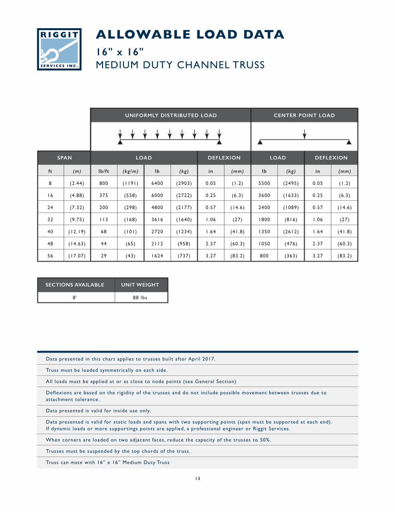
ALLOWABLE LOAD DATA16" x 16"MEDIUM DUTY CHANNEL TRUSS
Data presented in this chart applies to trusses built after April 2017.
Truss must be loaded symmetrically on each side.
All loads must be applied at or as close to node points (see General Section)
Deflexions are based on the rigidity of the trusses and do not include possible movement between trusses due to attachment tolerance.
Data presented is valid for inside use only.
Data presented is valid for static loads and spans with two supporting points (span must be supported at each end). If dynamic loads or more supportings points are applied, a professional engineer or Riggit Services.
When corners are loaded on two adjacent faces, reduce the capacity of the trusses to 50%.
Trusses must be suspended by the top chords of the truss.
Truss can mate with 16” x 16” Medium Duty Truss
SECTIONS AVAILABLE UNIT WEIGHT
88 lbs8'
ft (m) lb/ft (kg/m) lb (kg) in (mm) lb (kg) in (mm)
8 (2.44) 800 (1191) 6400 (2903) 0.05 (1.2) 5500 (2495) 0.05 (1.2)
16 (4.88) 375 (558) 6000 (2722) 0.25 (6.3) 3600 (1633) 0.25 (6.3)
24 (7.32) 200 (298) 4800 (2177) 0.57 (14.6) 2400 (1089) 0.57 (14.6)
32 (9.75) 113 (168) 3616 (1640) 1.06 (27) 1800 (816) 1.06 (27)
40 (12.19) 68 (101) 2720 (1234) 1.64 (41.8) 1350 (2612) 1.64 (41.8)
48 (14.63) 44 (65) 2112 (958) 2.37 (60.3) 1050 (476) 2.37 (60.3)
56 (17.07) 29 (43) 1624 (737) 3.27 (83.2) 800 (363) 3.27 (83.2)
SPAN LOAD DEFLEXION DEFLEXIONLOAD
UNIFORMLY DISTRIBUTED LOAD CENTER POINT LOAD
13
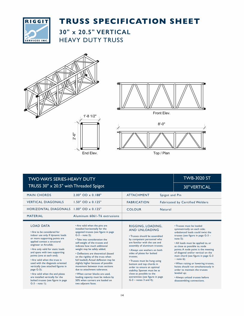
TRUSS SPECIFICATION SHEET30" x 20.5" VERTICALHEAVY DUTY TRUSS
TWO WAYS SERIES-HEAVY DUTY
TRUSS 30" x 20.5" with Threaded Spigot
MAIN CHORDS 2.00" OD x 0.188"
VERTICAL DIAGONALS 1.50" OD x 0.125"
HORIZONTAL DIAGONALS 1.00" OD x 0.125"
MATERIAL Aluminum 6061-T6 extrusions
ATTACHMENT Spigot and Pin
FABRICATION Fabricated by Certif ied Welders
COLOUR Natural
TWB-3020 ST
30" VERTICAL
RIGGING, LOADING,AND UNLOADING
• Trusses should be assembled by competent personnel who are familiar with the use and assembly of aluminum trusses;
• Always use washers on both sides of plates for bolted trusses;
• Trusses must be hung using bottom and top chords in order to ensure an optimal stability. Spanset must be as close as possible to the extremities (see figure in page G-3 – notes 3 and 4);
• Are valid when the pins are installed horizontally for the spigoted trusses (see figure in page G-3 – note 2);
• Take into consideration the self-weight of the trusses and indicate how much additional weight may be safely added;
• Deflexions are theoretical (based on the rigidity of the truss when full loaded). Actual deflexion may be slightly higher because of possible movement between truss sections due to attachment tolerance;
• When corner blocks are used, loading capacity must be reduce by 50% when corners are loaded on two adjacent faces.
• Trusses must be loaded symmetrically on each side; unbalanced loads could twist the trusses (see figure in page G-3 – note 5);
• All loads must be applied to, or as close as possible to, node points. A node point is the meeting of diagonal and/or vertical on the main chord (see figure in page G-3 – note 6);
• When raising or lowering trusses, hoists should run simultaneously in order to maintain the trusses leveled up;
• Always unload trusses before disassembling connections.
LOAD DATA
• Are to be considered for indoor use only. If dynamic loads or more supporting points are applied contact a structural engineer or Arcofab;
• Are only valid for static loads and spans with two supporting points (one at each end);
• Are valid when the truss is used with the diagonals oriented vertically (see attached figures in page G-3);
• Are valid when the end plates are installed vertically for the bolted trusses (see figure in page G-3 – note 1);
14
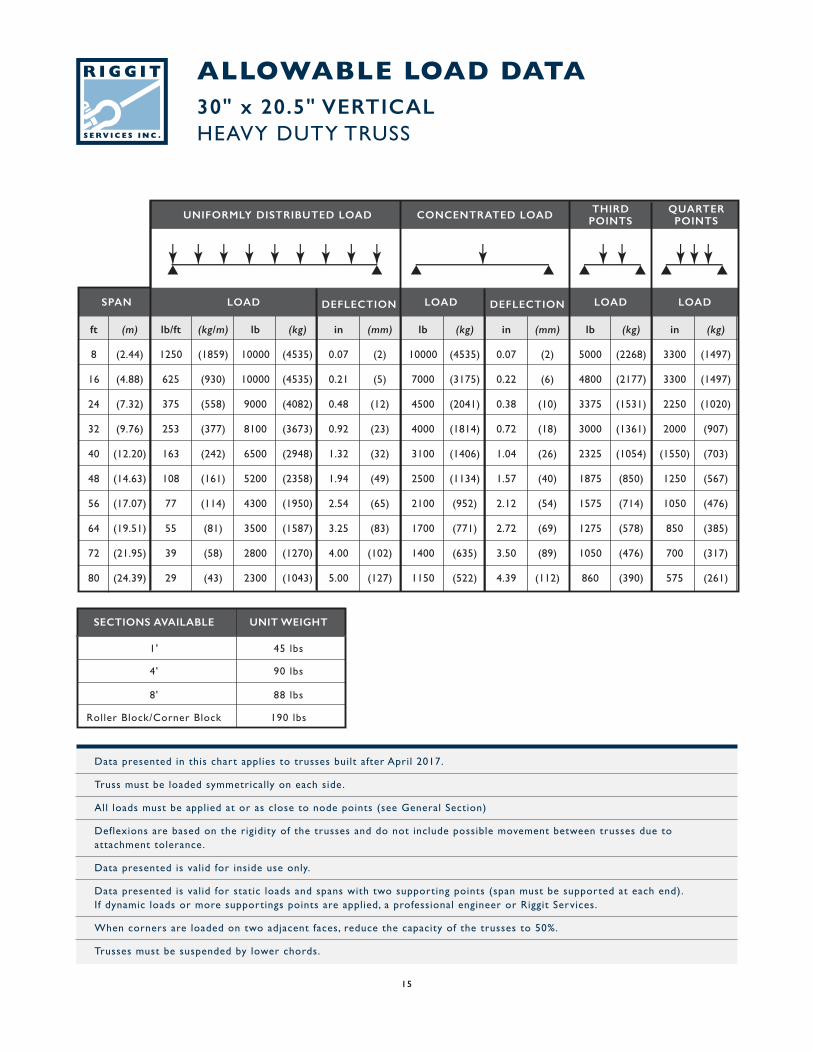
Data presented in this chart applies to trusses built after April 2017.
Truss must be loaded symmetrically on each side.
All loads must be applied at or as close to node points (see General Section)
Deflexions are based on the rigidity of the trusses and do not include possible movement between trusses due to attachment tolerance.
Data presented is valid for inside use only.
Data presented is valid for static loads and spans with two supporting points (span must be supported at each end). If dynamic loads or more supportings points are applied, a professional engineer or Riggit Services.
When corners are loaded on two adjacent faces, reduce the capacity of the trusses to 50%.
Trusses must be suspended by lower chords.
ALLOWABLE LOAD DATA30" x 20.5" VERTICALHEAVY DUTY TRUSS
ft (m) lb/ft (kg/m) lb (kg) in (mm) lb (kg) in (mm) lb (kg) in (kg)
8 (2.44) 1250 (1859) 10000 (4535) 0.07 (2) 10000 (4535) 0.07 (2) 5000 (2268) 3300 (1497)
16 (4.88) 625 (930) 10000 (4535) 0.21 (5) 7000 (3175) 0.22 (6) 4800 (2177) 3300 (1497)
24 (7.32) 375 (558) 9000 (4082) 0.48 (12) 4500 (2041) 0.38 (10) 3375 (1531) 2250 (1020)
32 (9.76) 253 (377) 8100 (3673) 0.92 (23) 4000 (1814) 0.72 (18) 3000 (1361) 2000 (907)
40 (12.20) 163 (242) 6500 (2948) 1.32 (32) 3100 (1406) 1.04 (26) 2325 (1054) (1550) (703)
48 (14.63) 108 (161) 5200 (2358) 1.94 (49) 2500 (1134) 1.57 (40) 1875 (850) 1250 (567)
56 (17.07) 77 (114) 4300 (1950) 2.54 (65) 2100 (952) 2.12 (54) 1575 (714) 1050 (476)
64 (19.51) 55 (81) 3500 (1587) 3.25 (83) 1700 (771) 2.72 (69) 1275 (578) 850 (385)
72 (21.95) 39 (58) 2800 (1270) 4.00 (102) 1400 (635) 3.50 (89) 1050 (476) 700 (317)
80 (24.39) 29 (43) 2300 (1043) 5.00 (127) 1150 (522) 4.39 (112) 860 (390) 575 (261)
SPAN LOAD DEFLECTIONDEFLECTION LOADLOADLOAD
UNIFORMLY DISTRIBUTED LOAD CONCENTRATED LOAD THIRDPOINTS
QUARTERPOINTS
SECTIONS AVAILABLE UNIT WEIGHT
45 lbs1'
90 lbs4'
88 lbs8'
190 lbsRoller Block/Corner Block
15
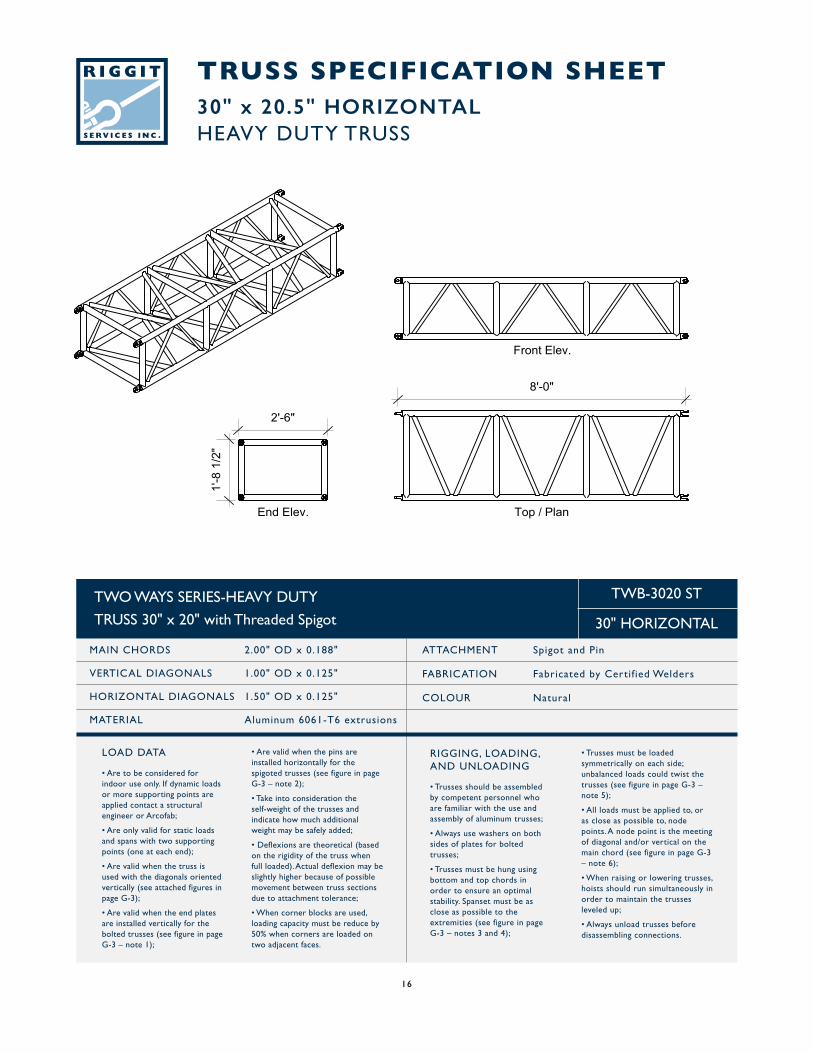
TRUSS SPECIFICATION SHEET30" x 20.5" HORIZONTALHEAVY DUTY TRUSS
TWO WAYS SERIES-HEAVY DUTY
TRUSS 30" x 20" with Threaded Spigot
MAIN CHORDS 2.00" OD x 0.188"
VERTICAL DIAGONALS 1.00" OD x 0.125"
HORIZONTAL DIAGONALS 1.50" OD x 0.125"
MATERIAL Aluminum 6061-T6 extrusions
ATTACHMENT Spigot and Pin
FABRICATION Fabricated by Certif ied Welders
COLOUR Natural
TWB-3020 ST
30" HORIZONTAL
RIGGING, LOADING,AND UNLOADING
• Trusses should be assembled by competent personnel who are familiar with the use and assembly of aluminum trusses;
• Always use washers on both sides of plates for bolted trusses;
• Trusses must be hung using bottom and top chords in order to ensure an optimal stability. Spanset must be as close as possible to the extremities (see figure in page G-3 – notes 3 and 4);
• Are valid when the pins are installed horizontally for the spigoted trusses (see figure in page G-3 – note 2);
• Take into consideration the self-weight of the trusses and indicate how much additional weight may be safely added;
• Deflexions are theoretical (based on the rigidity of the truss when full loaded). Actual deflexion may be slightly higher because of possible movement between truss sections due to attachment tolerance;
• When corner blocks are used, loading capacity must be reduce by 50% when corners are loaded on two adjacent faces.
• Trusses must be loaded symmetrically on each side; unbalanced loads could twist the trusses (see figure in page G-3 – note 5);
• All loads must be applied to, or as close as possible to, node points. A node point is the meeting of diagonal and/or vertical on the main chord (see figure in page G-3 – note 6);
• When raising or lowering trusses, hoists should run simultaneously in order to maintain the trusses leveled up;
• Always unload trusses before disassembling connections.
LOAD DATA
• Are to be considered for indoor use only. If dynamic loads or more supporting points are applied contact a structural engineer or Arcofab;
• Are only valid for static loads and spans with two supporting points (one at each end);
• Are valid when the truss is used with the diagonals oriented vertically (see attached figures in page G-3);
• Are valid when the end plates are installed vertically for the bolted trusses (see figure in page G-3 – note 1);
16
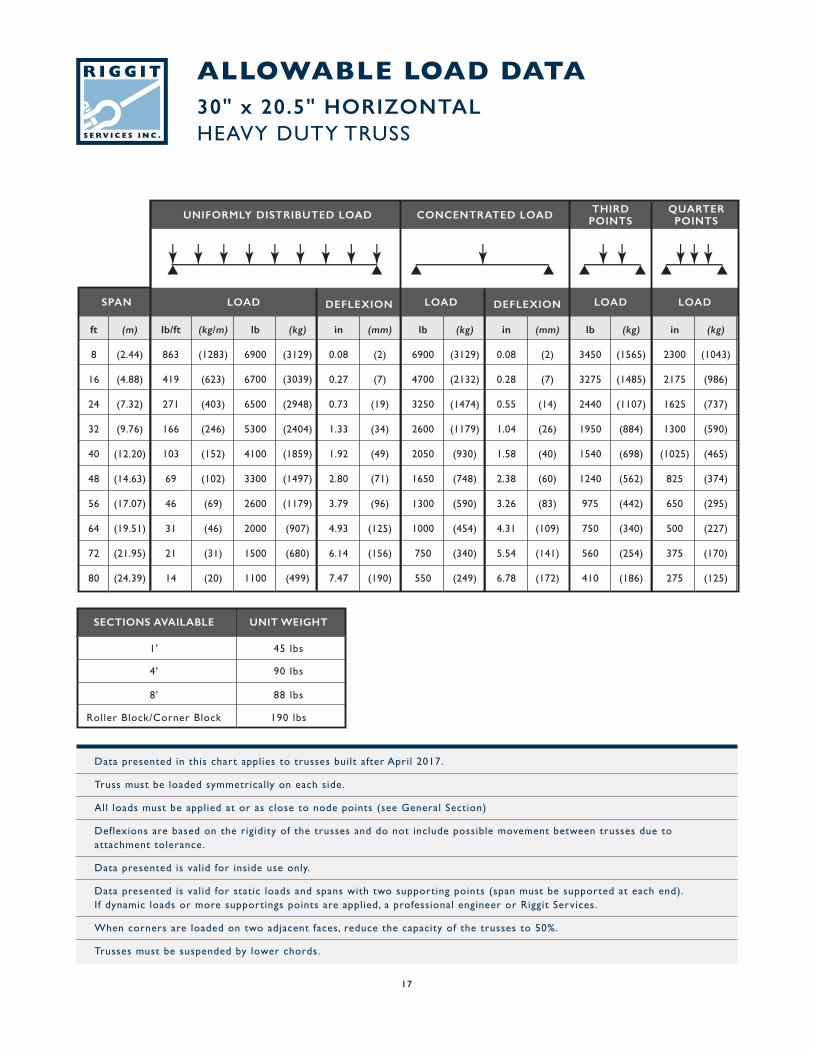
Data presented in this chart applies to trusses built after April 2017.
Truss must be loaded symmetrically on each side.
All loads must be applied at or as close to node points (see General Section)
Deflexions are based on the rigidity of the trusses and do not include possible movement between trusses due to attachment tolerance.
Data presented is valid for inside use only.
Data presented is valid for static loads and spans with two supporting points (span must be supported at each end). If dynamic loads or more supportings points are applied, a professional engineer or Riggit Services.
When corners are loaded on two adjacent faces, reduce the capacity of the trusses to 50%.
Trusses must be suspended by lower chords.
ALLOWABLE LOAD DATA30" x 20.5" HORIZONTALHEAVY DUTY TRUSS
ft (m) lb/ft (kg/m) lb (kg) in (mm) lb (kg) in (mm) lb (kg) in (kg)
8 (2.44) 863 (1283) 6900 (3129) 0.08 (2) 6900 (3129) 0.08 (2) 3450 (1565) 2300 (1043)
16 (4.88) 419 (623) 6700 (3039) 0.27 (7) 4700 (2132) 0.28 (7) 3275 (1485) 2175 (986)
24 (7.32) 271 (403) 6500 (2948) 0.73 (19) 3250 (1474) 0.55 (14) 2440 (1107) 1625 (737)
32 (9.76) 166 (246) 5300 (2404) 1.33 (34) 2600 (1179) 1.04 (26) 1950 (884) 1300 (590)
40 (12.20) 103 (152) 4100 (1859) 1.92 (49) 2050 (930) 1.58 (40) 1540 (698) (1025) (465)
48 (14.63) 69 (102) 3300 (1497) 2.80 (71) 1650 (748) 2.38 (60) 1240 (562) 825 (374)
56 (17.07) 46 (69) 2600 (1179) 3.79 (96) 1300 (590) 3.26 (83) 975 (442) 650 (295)
64 (19.51) 31 (46) 2000 (907) 4.93 (125) 1000 (454) 4.31 (109) 750 (340) 500 (227)
72 (21.95) 21 (31) 1500 (680) 6.14 (156) 750 (340) 5.54 (141) 560 (254) 375 (170)
80 (24.39) 14 (20) 1100 (499) 7.47 (190) 550 (249) 6.78 (172) 410 (186) 275 (125)
SPAN LOAD DEFLEXIONDEFLEXION LOADLOADLOAD
UNIFORMLY DISTRIBUTED LOAD CONCENTRATED LOAD THIRDPOINTS
QUARTERPOINTS
SECTIONS AVAILABLE UNIT WEIGHT
45 lbs1'
90 lbs4'
88 lbs8'
190 lbsRoller Block/Corner Block
17
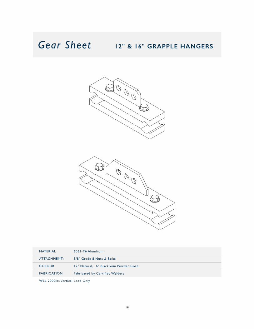
Gear Sheet 12" & 16" GRAPPLE HANGERS
MATERIAL 6061-T6 Aluminum
ATTACHMENT: 5/8" Grade 8 Nuts & Bolts
COLOUR 12" Natural, 16" Black Vein Powder Coat
FABRICATION Fabricated by Certif ied Welders
WLL 2000lbs Vertical Load Only
18
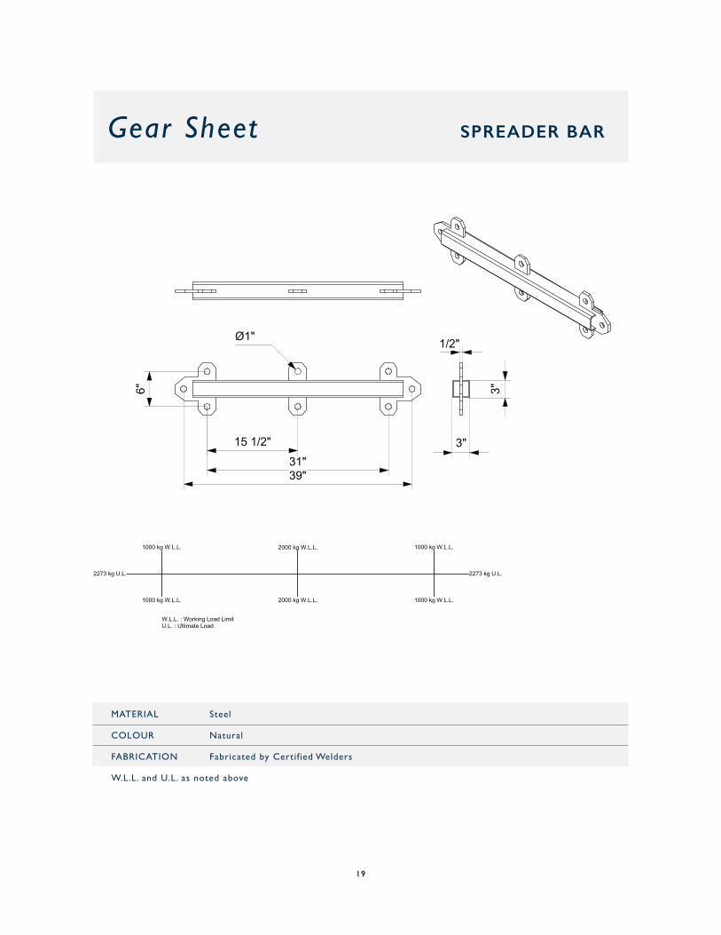
Gear Sheet SPREADER BAR
1/2"
3"
3"
31"39"
6"
15 1/2"
Ø1"
2000 kg W.L.L.
2000 kg W.L.L.
1000 kg W.L.L.
1000 kg W.L.L.
1000 kg W.L.L.
1000 kg W.L.L.
2273 kg U.L.2273 kg U.L.
W.L.L. : Working Load LimitU.L. : Ultimate Load
MATERIAL Steel
COLOUR Natural
FABRICATION Fabricated by Certif ied Welders
W.L.L. and U.L. as noted above
19
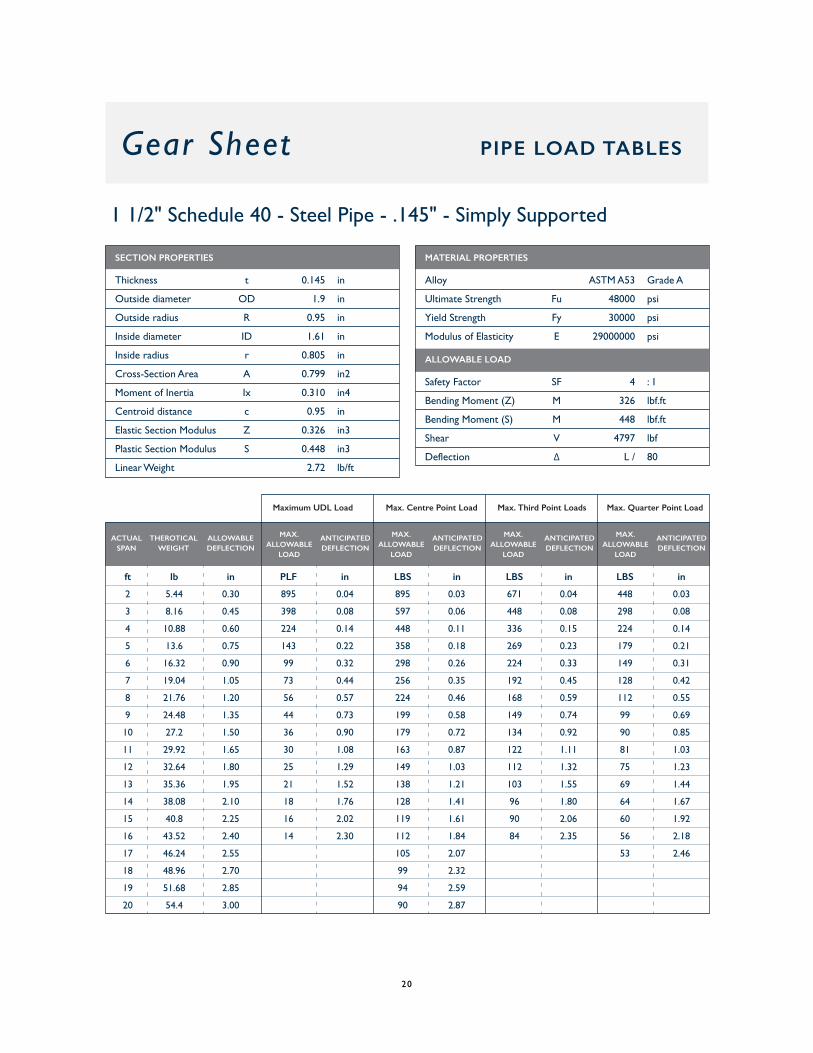
ft lb in PLF in LBS in LBS in LBS in
2 5.44 0.30 895 0.04 895 0.03 671 0.04 448 0.03
3 8.16 0.45 398 0.08 597 0.06 448 0.08 298 0.08
4 10.88 0.60 224 0.14 448 0.11 336 0.15 224 0.14
5 13.6 0.75 143 0.22 358 0.18 269 0.23 179 0.21
6 16.32 0.90 99 0.32 298 0.26 224 0.33 149 0.31
7 19.04 1.05 73 0.44 256 0.35 192 0.45 128 0.42
8 21.76 1.20 56 0.57 224 0.46 168 0.59 112 0.55
9 24.48 1.35 44 0.73 199 0.58 149 0.74 99 0.69
10 27.2 1.50 36 0.90 179 0.72 134 0.92 90 0.85
11 29.92 1.65 30 1.08 163 0.87 122 1.11 81 1.03
12 32.64 1.80 25 1.29 149 1.03 112 1.32 75 1.23
13 35.36 1.95 21 1.52 138 1.21 103 1.55 69 1.44
14 38.08 2.10 18 1.76 128 1.41 96 1.80 64 1.67
15 40.8 2.25 16 2.02 119 1.61 90 2.06 60 1.92
16 43.52 2.40 14 2.30 112 1.84 84 2.35 56 2.18
17 46.24 2.55 105 2.07 53 2.46
18 48.96 2.70 99 2.32
19 51.68 2.85 94 2.59
20 54.4 3.00 90 2.87
1 1/2" Schedule 40 - Steel Pipe - .145" - Simply Supported
Gear Sheet PIPE LOAD TABLES
SECTION PROPERTIES
Thickness t 0.145 in
Outside diameter OD 1.9 in
Outside radius R 0.95 in
Inside diameter ID 1.61 in
Inside radius r 0.805 in
Cross-Section Area A 0.799 in2
Moment of Inertia Ix 0.310 in4
Centroid distance c 0.95 in
Elastic Section Modulus Z 0.326 in3
Plastic Section Modulus S 0.448 in3
Linear Weight 2.72 lb/ft
MATERIAL PROPERTIES
Alloy ASTM A53 Grade A
Ultimate Strength Fu 48000 psi
Yield Strength Fy 30000 psi
Modulus of Elasticity E 29000000 psi
ALLOWABLE LOAD
Safety Factor SF 4 : 1
Bending Moment (Z) M 326 lbf.ft
Bending Moment (S) M 448 lbf.ft
Shear V 4797 lbf
Deflection ∆ L / 80
THEROTICALWEIGHT
ALLOWABLEDEFLECTION
MAX.ALLOWABLE
LOAD
ANTICIPATEDDEFLECTION
MAX.ALLOWABLE
LOAD
ANTICIPATEDDEFLECTION
MAX.ALLOWABLE
LOAD
ANTICIPATEDDEFLECTION
MAX.ALLOWABLE
LOAD
ANTICIPATEDDEFLECTION
ACTUALSPAN
Maximum UDL Load Max. Centre Point Load Max. Third Point Loads Max. Quarter Point Load
20
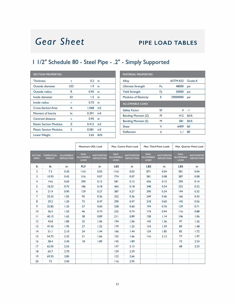
Gear Sheet PIPE LOAD TABLES
1 1/2" Schedule 80 - Steel Pipe - .2" - Simply Supported
ft lb in PLF in LBS in LBS in LBS in
2 7.3 0.30 1161 0.03 1161 0.03 871 0.04 581 0.04
3 10.95 0.45 516 0.07 774 0.07 581 0.08 387 0.08
4 14.6 0.60 290 0.12 581 0.12 436 0.15 290 0.14
5 18.25 0.75 186 0.18 465 0.18 348 0.24 232 0.22
6 21.9 0.90 129 0.27 387 0.27 290 0.34 194 0.32
7 25.55 1.05 95 0.36 332 0.36 249 0.46 166 0.43
8 29.2 1.20 73 0.47 290 0.47 218 0.60 145 0.56
9 32.85 1.35 57 0.60 258 0.60 194 0.76 129 0.71
10 36.5 1.50 46 0.74 232 0.74 174 0.94 116 0.88
11 40.15 1.65 38 0.89 211 0.89 158 1.14 106 1.06
12 43.8 1.80 32 1.06 194 1.06 145 1.36 97 1.26
13 47.45 1.95 27 1.25 179 1.25 134 1.59 89 1.48
14 51.1 2.10 24 1.44 166 1.44 124 1.85 83 1.72
15 54.75 2.25 21 1.66 155 1.66 116 2.12 77 1.97
16 58.4 2.40 18 1.89 145 1.89 73 2.24
17 62.05 2.55 137 2.13 68 2.53
18 65.7 2.70 129 2.39
19 69.35 2.85 122 2.66
20 73 3.00 116 2.95
SECTION PROPERTIES
Thickness t 0.2 in
Outside diameter OD 1.9 in
Outside radius R 0.95 in
Inside diameter ID 1.5 in
Inside radius r 0.75 in
Cross-Section Area A 1.068 in2
Moment of Inertia Ix 0.391 in4
Centroid distance c 0.95 in
Elastic Section Modulus Z 0.412 in3
Plastic Section Modulus S 0.581 in3
Linear Weight 3.65 lb/ft
MATERIAL PROPERTIES
Alloy ASTM A53 Grade A
Ultimate Strength Fu 48000 psi
Yield Strength Fy 30000 psi
Modulus of Elasticity E 29000000 psi
ALLOWABLE LOAD
Safety Factor SF 4 : 1
Bending Moment (Z) M 412 lbf.ft
Bending Moment (S) M 581 lbf.ft
Shear V 6409 lbf
Deflection ∆ L / 80
THEROTICALWEIGHT
ALLOWABLEDEFLECTION
MAX.ALLOWABLE
LOAD
ANTICIPATEDDEFLECTION
MAX.ALLOWABLE
LOAD
ANTICIPATEDDEFLECTION
MAX.ALLOWABLE
LOAD
ANTICIPATEDDEFLECTION
MAX.ALLOWABLE
LOAD
ANTICIPATEDDEFLECTION
ACTUALSPAN
Maximum UDL Load Max. Centre Point Load Max. Third Point Loads Max. Quarter Point Load
21
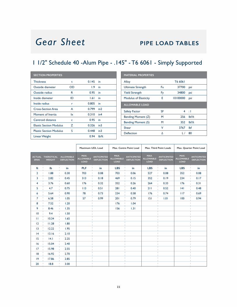
Gear Sheet PIPE LOAD TABLES
1 1/2" Schedule 40 -Alum Pipe - .145" - T6 6061 - Simply Supported
ft lb in PLF in LBS in LBS in LBS in
2 1.88 0.30 703 0.08 703 0.06 527 0.08 352 0.08
3 2.82 0.45 313 0.18 469 0.15 352 0.19 234 0.17
4 3.76 0.60 176 0.32 352 0.26 264 0.33 176 0.31
5 4.7 0.75 113 0.51 281 0.40 211 0.52 141 0.48
6 5.64 0.90 78 0.73 234 0.58 176 0.74 117 0.69
7 6.58 1.05 57 0.99 201 0.79 151 1.01 100 0.94
8 7.52 1.20 176 1.04
9 8.46 1.35 156 1.31
10 9.4 1.50
11 10.34 1.65
12 11.28 1.80
13 12.22 1.95
14 13.16 2.10
15 14.1 2.25
16 15.04 2.40
17 15.98 2.55
18 16.92 2.70
19 17.86 2.85
20 18.8 3.00
SECTION PROPERTIES
Thickness t 0.145 in
Outside diameter OD 1.9 in
Outside radius R 0.95 in
Inside diameter ID 1.61 in
Inside radius r 0.805 in
Cross-Section Area A 0.799 in2
Moment of Inertia Ix 0.310 in4
Centroid distance c 0.95 in
Elastic Section Modulus Z 0.326 in3
Plastic Section Modulus S 0.448 in3
Linear Weight 0.94 lb/ft
MATERIAL PROPERTIES
Alloy T6 6061
Ultimate Strength Fu 37700 psi
Yield Strength Fy 34800 psi
Modulus of Elasticity E 10100000 psi
ALLOWABLE LOAD
Safety Factor SF 4 : 1
Bending Moment (Z) M 256 lbf.ft
Bending Moment (S) M 352 lbf.ft
Shear V 3767 lbf
Deflection ∆ L / 80
THEROTICALWEIGHT
ALLOWABLEDEFLECTION
MAX.ALLOWABLE
LOAD
ANTICIPATEDDEFLECTION
MAX.ALLOWABLE
LOAD
ANTICIPATEDDEFLECTION
MAX.ALLOWABLE
LOAD
ANTICIPATEDDEFLECTION
MAX.ALLOWABLE
LOAD
ANTICIPATEDDEFLECTION
ACTUALSPAN
Maximum UDL Load Max. Centre Point Load Max. Third Point Loads Max. Quarter Point Load
22